1
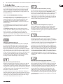
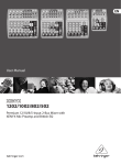
User Manual MULTICOM PRO-XL MDX4600 Reference-Class 4-Channel Expander/Gate/Compressor/Peak Limiter with Dynamic Enhancer and Low Contour Filter COMPOSER PRO-XL MDX2600 Reference-Class 2-Channel Expander/Gate/Compressor/Peak Limiter with Integrated De-Esser, Dynamic Enhancer and Tube Simulation AUTOCOM PRO-XL MDX1600 Reference-Class 2-Channel Expander/Gate/Compressor/Peak Limiter with Integrated Dynamic Enhancer, De-Esser and Low Contour Filter 2 MULTICOM PRO-XL MDX4600/PRO-XL MDX2600/AUTOCOM PRO-XL MDX1600 User Manual Table of Contents Important Safety Instructions....................................... 3 Legal Disclaimer.............................................................. 3 Limited Warranty............................................................ 3 1. Introduction................................................................ 5 1.1 Before you get started....................................................... 6 1.1.1 Shipment........................................................................... 6 1.1.2 Initial operation.............................................................. 6 1.1.3 Warranty............................................................................ 6 1.2 The user’s manual................................................................ 6 2. Control Elements and Connectors............................ 6 2.1 The expander/gate section.............................................. 6 2.2 The compressor section.................................................... 7 2.3 The dynamic enhancer section...................................... 8 2.4 The de-esser section.......................................................... 8 2.5 The peak limiter section.................................................... 9 2.6 The rear panel control elements.................................... 9 3. Examples of Sidechain Applications........................ 9 3.1 Eliminating interference.................................................... 9 3.2 Emphasizing instruments............................................... 10 3.3 Time-delayed compression........................................... 10 3.4 “Voice over” compression (“ducking”)....................... 10 3.5 Triggering additional sounds from a rhythm track................................................................................ 10 4. Wiring........................................................................ 10 5. Installation................................................................ 11 5.1 Rack installation ................................................................ 11 5.2 Audio connections............................................................ 11 6. Specifications............................................................ 12 3 MULTICOM PRO-XL MDX4600/PRO-XL MDX2600/AUTOCOM PRO-XL MDX1600 User Manual Important Safety Instructions Terminals marked with this symbol carry electrical current of sufficient magnitude to constitute risk of electric shock. Use only high-quality professional speaker cables with ¼" TS or twist-locking plugs pre-installed. All other installation or modification should be performed only by qualified personnel. This symbol, wherever it appears, alerts you to the presence of uninsulated dangerous voltage inside the enclosure - voltage that may be sufficient to constitute a risk of shock. This symbol, wherever it appears, alerts you to important operating and maintenance instructions in the accompanying literature. Please read the manual. Caution To reduce the risk of electric shock, do not remove the top cover (or the rear section). No user serviceable parts inside. Refer servicing to qualified personnel. Caution To reduce the risk of fire or electric shock, do not expose this appliance to rain and moisture. The apparatus shall not be exposed to dripping or splashing liquids and no objects filled with liquids, such as vases, shall be placed on the apparatus. 9. Do not defeat the safety purpose of the polarized or grounding-type plug. A polarized plug has two blades with one wider than the other. A grounding-type plug has two blades and a third grounding prong. The wide blade or the third prong are provided for your safety. If the provided plug does not fit into your outlet, consult an electrician for replacement of the obsolete outlet. 10. Protect the power cord from being walked on or pinched particularly at plugs, convenience receptacles, and the point where they exit from the apparatus. 11. Use only attachments/accessories specified by the manufacturer. 12. Use only with the cart, stand, tripod, bracket, or table specified by the manufacturer, or sold with the apparatus. When a cart is used, use caution when moving the cart/apparatus combination to avoid injury from tip-over. 13. Unplug this apparatus during lightning storms or when unused for long periods of time. 14. Refer all servicing to qualified service personnel. Servicing is required when the apparatus has been damaged in any way, such as power supply cord or plug is damaged, liquid has been spilled or objects have fallen into the apparatus, the apparatus has been exposed to rain or moisture, does not operate normally, or has been dropped. 15. The apparatus shall be connected to a MAINS socket outlet with a protective earthing connection. 16. Where the MAINS plug or an appliance coupler is used as the disconnect device, the disconnect device shall remain readily operable. Caution These service instructions are for use by qualified service personnel only. To reduce the risk of electric shock do not perform any servicing other than that contained in the operation instructions. Repairs have to be performed by qualified service personnel. 1. Read these instructions. 2. Keep these instructions. 3. Heed all warnings. 4. Follow all instructions. 5. Do not use this apparatus near water. 6. Clean only with dry cloth. 7. Do not block any ventilation openings. Install in accordance with the manufacturer’s instructions. 8. Do not install near any heat sources such as radiators, heat registers, stoves, or other apparatus (including amplifiers) that produce heat. LEGAL DISCLAIMER TECHNICAL SPECIFICATIONS AND APPEARANCES ARE SUBJECT TO CHANGE WITHOUT NOTICE AND ACCURACY IS NOT GUARANTEED. BEHRINGER IS PART OF THE MUSIC GROUP (MUSIC-GROUP.COM). ALL TRADEMARKS ARE THE PROPERTY OF THEIR RESPECTIVE OWNERS. MUSIC GROUP ACCEPTS NO LIABILITY FOR ANY LOSS WHICH MAY BE SUFFERED BY ANY PERSON WHO RELIES EITHER WHOLLY OR IN PART UPON ANY DESCRIPTION, PHOTOGRAPH OR STATEMENT CONTAINED HEREIN. COLORS AND SPECIFICATIONS MAY VARY FROM ACTUAL PRODUCT. MUSIC GROUP PRODUCTS ARE SOLD THROUGH AUTHORIZED FULLFILLERS AND RESELLERS ONLY. FULLFILLERS AND RESELLERS ARE NOT AGENTS OF MUSIC GROUP AND HAVE ABSOLUTELY NO AUTHORITY TO BIND MUSIC GROUP BY ANY EXPRESS OR IMPLIED UNDERTAKING OR REPRESENTATION. THIS MANUAL IS COPYRIGHTED. NO PART OF THIS MANUAL MAY BE REPRODUCED OR TRANSMITTED IN ANY FORM OR BY ANY MEANS, ELECTRONIC OR MECHANICAL, INCLUDING PHOTOCOPYING AND RECORDING OF ANY KIND, FOR ANY PURPOSE, WITHOUT THE EXPRESS WRITTEN PERMISSION OF MUSIC GROUP IP LTD. ALL RIGHTS RESERVED. © 2012 MUSIC Group IP Ltd. Trident Chambers, Wickhams Cay, P.O. Box 146, Road Town, Tortola, British Virgin Islands LIMITED WARRANTY § 1 Warranty (1) This limited warranty is valid only if you purchased the product from a MUSIC Group Authorized Reseller in the country of purchase. A list of authorized resellers can be found on BEHRINGER’s website behringer.com under “Where to Buy”, or you can contact the MUSIC Group office closest to you. (2) MUSIC Group* warrants the mechanical and electronic components of this product to be free of defects in material and workmanship if used under normal operating conditions for a period of one (1) year from the original date of purchase (see the Limited Warranty terms in § 4 below), unless a longer minimum warranty period is mandated by applicable local laws. If the product shows any defects within the specified warranty period and that defect is not excluded under § 4, MUSIC Group shall, at its discretion, either replace or repair the product using suitable new or reconditioned product or parts. In case MUSIC Group decides to replace the entire product, this limited warranty shall apply to the replacement product for the remaining initial warranty period, i.e., one (1) year (or otherwise applicable minimum warranty period) from the date of purchase of the original product. (3) Upon validation of the warranty claim, the repaired or replacement product will be returned to the user freight prepaid by MUSIC Group. (4) Warranty claims other than those indicated above are expressly excluded. PLEASE RETAIN YOUR SALES RECEIPT. IT IS YOUR PROOF OF PURCHASE COVERING YOUR LIMITED WARRANTY. THIS LIMITED WARRANTY IS VOID WITHOUT SUCH PROOF OF PURCHASE. § 2 Online registration Please do remember to register your new BEHRINGER equipment right after your purchase at behringer.com under “Support” and kindly read the terms and conditions of our limited warranty carefully. Registering your purchase and equipment with us helps us process your repair claims quicker and more efficiently. Thank you for your cooperation! § 3 Return materials authorization (1) To obtain warranty service, please contact the retailer from whom the equipment was purchased. Should your MUSIC Group Authorized Reseller not be located in your vicinity, you may contact the MUSIC Group Authorized Fulfiller for your country listed under 4 MULTICOM PRO-XL MDX4600/PRO-XL MDX2600/AUTOCOM PRO-XL MDX1600 User Manual “Support” at behringer.com. If your country is not listed, please check if your problem can be dealt with by our “Online Support” which may also be found under “Support” at behringer.com. Alternatively, please submit an online warranty claim at behringer.com BEFORE returning the product. All inquiries must be accompanied by a description of the problem and the serial number of the product. After verifying the product’s warranty eligibility with the original sales receipt, MUSIC Group will then issue a Return Materials Authorization (“RMA”) number. (2) Subsequently, the product must be returned in its original shipping carton, together with the return authorization number to the address indicated by MUSIC Group. (3) Shipments without freight prepaid will not be accepted. § 4 Warranty Exclusions (1) This limited warranty does not cover consumable parts including, but not limited to, fuses and batteries. Where applicable, MUSIC Group warrants the valves or meters contained in the product to be free from defects in material and workmanship for a period of ninety (90) days from date of purchase. (2) This limited warranty does not cover the product if it has been electronically or mechanically modified in any way. If the product needs to be modified or adapted in order to comply with applicable technical or safety standards on a national or local level, in any country which is not the country for which the product was originally developed and manufactured, this modification/adaptation shall not be considered a defect in materials or workmanship. This limited warranty does not cover any such modification/adaptation, regardless of whether it was carried out properly or not. Under the terms of this limited warranty, MUSIC Group shall not be held responsible for any cost resulting from such a modification/adaptation. (3) This limited warranty covers only the product hardware. It does not cover technical assistance for hardware or software usage and it does not cover any software products whether or not contained in the product. Any such software is provided “AS IS” unless expressly provided for in any enclosed software limited warranty. (4) This limited warranty is invalid if the factory-applied serial number has been altered or removed from the product. (5) Free inspections and maintenance/repair work are expressly excluded from this limited warranty, in particular, if caused by improper handling of the product by the user. This also applies to defects caused by normal wear and tear, in particular, of faders, crossfaders, potentiometers, keys/buttons, guitar strings, illuminants and similar parts. (6) Damage/defects caused by the following conditions are not covered by this limited warranty: • improper handling, neglect or failure to operate the unit in compliance with the instructions given in BEHRINGER user or service manuals; • connection or operation of the unit in any way that does not comply with the technical or safety regulations applicable in the country where the product is used; • damage/defects caused by acts of God/Nature (accident, fire, flood, etc) or any other condition that is beyond the control of MUSIC Group. (7) Any repair or opening of the unit carried out by unauthorized personnel (user included) will void the limited warranty. (8) If an inspection of the product by MUSIC Group shows that the defect in question is not covered by the limited warranty, the inspection costs are payable by the customer. (9) Products which do not meet the terms of this limited warranty will be repaired exclusively at the buyer’s expense. MUSIC Group or its authorized service center will inform the buyer of any such circumstance. If the buyer fails to submit a written repair order within 6 weeks after notification, MUSIC Group will return the unit C.O.D. with a separate invoice for freight and packing. Such costs will also be invoiced separately when the buyer has sent in a written repair order. (10) MUSIC Group Authorized Resellers do not sell new products directly in online auctions. Purchases made through an online auction are on a “buyer beware” basis. Online auction confirmations or sales receipts are not accepted for warranty verification and MUSIC Group will not repair or replace any product purchased through an online auction. § 5 Warranty transferability This limited warranty is extended exclusively to the original buyer (customer of authorized reseller) and is not transferable to anyone who may subsequently purchase this product. No other person (reseller, etc.) shall be entitled to give any warranty promise on behalf of MUSIC Group. § 6 Claim for damage Subject only to the operation of mandatory applicable local laws, MUSIC Group shall have no liability to the buyer under this warranty for any consequential or indirect loss or damage of any kind. In no event shall the liability of MUSIC Group under this limited warranty exceed the invoiced value of the product. § 7 Limitation of liability This limited warranty is the complete and exclusive warranty between you and MUSIC Group. It supersedes all other written or oral communications related to this product. MUSIC Group provides no other warranties for this product. § 8 Other warranty rights and national law (1) This limited warranty does not exclude or limit the buyer’s statutory rights as a consumer in any way. (2) The limited warranty regulations mentioned herein are applicable unless they constitute an infringement of applicable mandatory local laws. (3) This warranty does not detract from the seller’s obligations in regard to any lack of conformity of the product and any hidden defect. § 9 Amendment Warranty service conditions are subject to change without notice. For the latest warranty terms and conditions and additional information regarding MUSIC Group’s limited warranty, please see complete details online at behringer.com. * MUSIC Group Macao Commercial Offshore Limited of Rue de Pequim No. 202-A, Macau Finance Centre 9/J, Macau, including all MUSIC Group companies 5 MULTICOM PRO-XL MDX4600/PRO-XL MDX2600/AUTOCOM PRO-XL MDX1600 User Manual 1. Introduction With this new dynamics processor from the PRO-XL series you have acquired an extremely powerful and universal compressor which unites in one compact device all of those dynamics control functions that are most frequently used in practice: each channel has an independent compressor/limiter, expander/ gate and peak limiter. Thus, virtually all dynamics processing problems can be remedied with little effort. Future-oriented BEHRINGER technology The new PRO-XL dynamics processors from BEHRINGER feature several innovative circuit designs, making them top-class dynamics processing equipment. Compared to their predecessors, they now have improvements such as the de-esser, which allows you to effectively suppress disturbing hiss noise (COMPOSER PRO-XL), additional LED displays to set the de-esser levels, plus a switchable enhancer. The AUTOCOM PRO-XL not only includes an enhancer, but also a switchable de-esser and a peak limiter, which has already proved its versatility in the COMPOSER PRO. The BEHRINGER MULTICOM PRO-XL has been upgraded with an expander/ noise gate plus enhancer. Additionally, we have managed to improve its audio properties even further—in combination with a revised circuit design. To give you the best operational reliability possible, we manufacture our products in accordance with the highest quality standards known in the industry. Additionally the dynamic processors are manufactured under ISO9000 certified management system. VAD (Voice-Adaptive) De-esser The COMPOSER PRO-XL and AUTOCOM PRO‑XL incorporate a newly designed de-esser circuit specifically adapted to process the critical range of treble frequencies. Hiss noise on vocal tracks often contains high levels, giving the signals a rather edgy, unpleasant sound. The de-esser responds to those frequency ranges in which hiss noise usually occurs and limits the overall signal level as soon as the audio signal is affected by excessive energy density in this range. Unlike equalizers, however, it does not impair the frequency response of the signal. In this way, intelligibility in low-level passages is perfectly preserved, and you can even boost the treble range with a good equalizer. The sound becomes transparent and fresh, while the de-esser prevents hiss noise from becoming too dominant and disturbing the overall sound image. IDE (Interactive Dynamic) Enhancer Probably the best known negative side effect of a compressor is the “dull” and “compressed” sound that is likely to result from the processing of complex program material. Low-frequency instruments usually produce the highest signal energy and hence make the compressor reduce the overall level. Any instrument in the higher frequency ranges concurrently played also has its level reduced, which leads to a “compressed” overall sound. The dynamic enhancer provides the solution to this problem, enabling you to make up specifically for the compression-induced loss of treble energy. Since the enhancer can detect the amount of compression applied, it does not change the sound image as long as the signals remain uncompressed. No treble energy is lost, even when complex mix-down material is processed. ATS (Authentic Tube Simulation) circuitry Even today, the warm, expressive and transparent tonal character of electronic tubes is a real “classic”. We proudly present the COMPOSER PRO-XL and its high-tech circuit design enabling the authentic reproduction of this legendary sound, and at the same time avoiding all of the technical drawbacks that go along with tube technology. Owing to state-of-the-art semi-conductor technology, there is no sound deterioration caused by tube ageing, there are no heat problems and no maintenance required at all. All that remains is the advantage of tube technology: its distinctive sound! IKA (Interactive Knee Adaptation) Compressor Our proven IKA (Interactive Knee Adaptation) circuit successfully combines the “hard knee” compressor concept with the “soft knee” characteristic. This program-dependent control characteristic makes it possible to both provide an “inaudible” and musical program compression and allows for creative and efficient dynamics processing. IRC (Interactive Ratio Control) Expander A fundamental problem when using a compressor is the fact that the basic noise floor depends on the amount of compression applied, i.e. it is amplified maximally in low-level passages and breaks in the music (compressor noise). To eliminate this problem, compressors are usually equipped with additional expander or gate circuitry, simply fading out the noise during breaks. The dynamics processors from the PRO-XL Series feature our IRC (Interactive Ratio Control) expander, whose ratio setting changes automatically with the program material. The result is an expander that can be set quickly and easily, and does not cut off low-level wanted signals (e.g. the first or last syllable of a word in a vocal track). With the new IRC circuit, the expander/gate section of the BEHRINGER COMPOSER PRO-XL MDX2600, AUTOCOM PRO-XL MDX1600 and MULTICOM PRO-XL MDX4600 can be used as an independent device to eliminate any kind of interference, thus giving you almost unlimited flexibility of application. IGC (Interactive Gain Control) Peak Limiter Another outstanding feature of BEHRINGER dynamics processors is the IGC (Interactive Gain Control) limiter, an intelligent combination of a clipper and program limiter. The clipper comes in as soon as an adjustable threshold is exceeded and abruptly limits the signal gain. However, if the limiter threshold is exceeded for longer than a few milliseconds, the ICG circuit is activated automatically and reduces the gain of the overall output signal, so that audible distor-tion is eliminated (program limiter). When the signal drops below threshold again, its level is restored to its original value after about one second. This IGC feature is an extremely usefull tool for both live applications (e.g. speaker protection) and digital processing, in which excess levels lead to unpleasant distortion. 6 MULTICOM PRO-XL MDX4600/PRO-XL MDX2600/AUTOCOM PRO-XL MDX1600 User Manual Safety relay 1.2 The user’s manual The design of the COMPOSER PRO-XL incorporates the so-called safety relays, which set the unit to bypass in case of a power failure or other malfunctions. Additionally, these relays are used to implement a switch-on delay, so as to suppress harmful switch-on thumps. This manual has been designed to give you a survey of all control elements and at the same time provide you with detailed information on how to use them. To help you understand what each control does, we have grouped the control elements according to function. If you need more detailed information on specific topics, please visit our website at behringer.com, where you will find for example explanations of in-detail dynamics applications. Balanced inputs and outputs The BEHRINGER dynamics processors from the PRO-XL series are equipped with electronically balanced inputs and outputs. The automatic servo function detects any unbalanced plugs connec-ted and adjusts the nominal level internally, so as to make sure that there is no difference in level between the input and output signals (6-dB correction). ◊ First, this manual describes the terminology used, so that you understand the unit and its functions. Please read the manual carefully and keep it for future reference. 2. Control Elements and Connectors This chapter describes the various control elements of your dynamics processor. All controls are explained in full detail, including useful suggestions on how to use them. The COMPOSER PRO-XL and AUTOCOM PRO-XL feature two identical channels, the MULTICOM PRO-XL four of them. 1.1 Before you get started 1.1.1 Shipment Your COMPOSER PRO-XL, AUTOCOM PRO-XL or MULTICOM PRO-XL was carefully packed at the factory and the packaging is designed to protect the unit from rough hand-ling. Nevertheless, we recommend that you carefully examine the packaging and its contents for any signs of physical damage which may have occurred during transit. ◊ If the unit is damaged, please do NOT return it to BEHRINGER, but notify your dealer and the shipping company immediately. Otherwise, claims for damage or replacement may not be granted. 1.1.2 Initial operation Be sure that there is enough space around the unit for cooling and, to avoid overheating, please do not place it on power amplifiers, near radiators etc. ◊ Before you connect the unit to the mains, please make sure that the voltage setting on the unit matches the local voltage: The fuse holder at the AC power connector has 3 triangular markings. Two of these three triangles are aligned with one another. The unit is set to the voltage shown next to these markings and can be switched over by turning the fuse holder by 180°. IMPORTANT: This does not apply to export models designed exclusively for 115 V operation! MDX1600 MDX2600 MDX4600 Fig. 2.1: Linking channels with the COUPLE switch (1) Pressing the COUPLE switch links the channels. In couple mode, dynamics are controlled by using channel 1 switches and controls, whereby the control signal is derived from the energy of both side chain channels (true stereo processing). Therefore, all switches and controls of channel 2 (except for IN/OUT, SC EXT, SC MON, LO CONTOUR, TUBE, DE-ESSER, MALE, ENHANCER, I/O METER switches and OUTPUT, DE-ESSER LEVEL and ENHANCER LEVEL controls) will be disabled when you activate the COUPLE switch. On the MDX4600, channel 3 controls channel 4 in link mode. 2.1 The expander/gate section (3) (4) ◊ If you set the unit to a different mains voltage, be sure to use a fuse of the correct type and rating. Please refer to the “Specifications” for details. ◊ Blown fuses must be replaced by fuses of the same type and rating! Please refer to the “Specifications” for details. The mains connection is made using the enclosed power cord and a standard IEC receptacle. It meets all of the international safety certification requirements. ◊ Please make sure that all units have a proper ground connection. For your own safety, never remove or disable the ground conductor from the unit or of the AC power cord. 1.1.3 Warranty Please take the time to fill in and return the warranty card within 14 days after the date of purchase, so as to benefit from our extended warranty. The serial number is printed on the top side of the unit. Or register online at behringer.com. (2)(5) Fig. 2.2: Expander/gate section control elements (2) Use the TRIGGER control in the expander/gate section to determine the threshold below which expansion sets in, so that signals below threshold are reduced in gain. The setting range is from OFF to +10 dB. (3) If a signal below the adjusted value is applied, the red LED (expansion on) lights up. If the signal gain is above the adjusted value, the green LED lights up. (4) In order to adapt the expander/gate optimally to the program material, use the RELEASE switch to select a short or long release time. Percussive material with little or no reverb at all is usually processed with a short release time (switch not pressed). The long release time is the best choice for slowly decaying or heavily reverberated signals (switch pressed). (5) The GATE switch allows you to toggle between the expander (switch not pressed) and the gate function (switch pressed). Use the gate function to mute signals below threshold (e.g. noise). 7 MULTICOM PRO-XL MDX4600/PRO-XL MDX2600/AUTOCOM PRO-XL MDX1600 User Manual Application hints The purpose of using an expander is usually to expand the usable dynamics towards the lower end, i.e. to improve the separation between low-level signals and the unavoidable noise floor by reducing the noise level. Start setting up the expander by turning the TRIGGER control from position OFF clockwise until the LEDs show the onset of the gain reduction. Preferrably, you should use some music material containing pauses and soft passages, so as to hear whether the beginnings or endings of words are cut off by the expander or are suppressed too much. If necessary, experiment with the release time or reduce the threshold a little bit. Gates work basically in the same way, the major difference being the fact that they reduce gain to a much greater extent. Once the level drops below threshold, the signal is muted completely. The classic application of a gate is the separation of signals delivered by multiple microphones in a multitrack recording. Especially when drums are recorded, a gate is almost indispensable to avoid crosstalk, e.g. of the cymbals into the floor tom microphones. However, you should always try to use the microphones and their directivity in the first place to achieve some degree of channel separation and hence a better and more natural result. Subsequently, a gate helps you optimize your set-up. The program-dependent IRC allows you to set both gate and expander easily and conveniently. Nevertheless, you should experiment with different release times and trigger settings to get a perfect result! 2.2 The compressor section (11) (12) (14) (19) (20) (6) Use the THRESHOLD control to adjust the compressor threshold from -40 to +20 dB. (7) These three LEDs (AUTOCOM PRO‑XL and COMPOSER PRO‑XL only) indicate whether the input signal is above or below the adjusted compressor threshold. The yellow LED in the middle refers to the IKA “soft knee” range (if IKA is on). (8) Activating the SC EXT switch interrupts the link between the signal input and the compressor control section. At the same time, an external control signal can be fed in via the rear panel SC RETURN jack, taking over control of the input signal dynamics reduction. You can, for example, intensify the control function in a specific frequency range by inserting an equalizer via the SC SEND AND SC RETURN jacks. Detailed information on this special application can be found in chapter 3 “Examples of Sidechain Applications”. This function, too, is only available on the AUTOCOM PRO-XL and COMPOSER PRO‑XL. (9) The SC MON switch links the sidechain input signal to the audio output, thereby muting the audio input signal. For example, this allows you to pre-monitor the sidechain signal in combination with an equalizer or other device inserted into the sidechain channel. The SC MONITOR function makes it easier to for example adapt the equalizer filters to the control signal. ◊ With the SC MONITOR switch activated, only the side-chain signal will be present at the output, which is shown by the flashing LED switch! (10) The RATIO control determines the ratio of input vs. output level with regard to all signals exceeding threshold by more than 10 dB. Although the compression starts earlier, the IKA characteristic ensures the smooth, inaudible onset of the gain reduction, which is why the ratio value will be reached only with 10 dB or more above threshold. It can be set continuously from 1:1 (no compression) to oo :1 (limiter). (11) The 12-digit GAIN REDUCTION display (MDX4600: 8-digit) informs you about the current gain reduction applied (1 to 30 dB). (12) The LO CONTOUR switch activates a high-pass filter in the side-chain path and thus avoids the “pumping” effect caused by high-energy bass frequencies and their influence on the compression process. (6)(22) (10) (18) (21) MDX4600 (7) (9) (11) (14) (17) (19) (20) (6) (8) (10) (12) (13) (15) (16) (22) (18) (21) MDX4600 (7) (9) (11) (14) (19) (20) (6) (8) (10) (12) (13) (15) (16) (25) (18) (21) MDX1600 Fig. 2.3: Compressor section control elements (13) Use the ATTACK control to determine when the compression sets in once the signal has exceeded threshold (MDX1600 and MDX2600 only). The setting range is from 0.3 to 300 ms. (14) Press the INTERACTIVE KNEE switch to change from “hard knee” to IKA characteristic: Input signals exceeding threshold by up to 10 dB will be processed with a “soft knee” characteristic. Above 10 dB the control characteristic changes from “soft knee” to a more conventional “hard knee” compression. The IKA characteristic allows for a subtle and musical compression of the program material, and should be used whenever inaudible compression is desired. (15) The AUTO function, which is activated with the AUTO switch, disables the ATTACK and RELEASE controls and derives these time values automatically from the program material. It thus allows for a heavy and, at the same time, musical compression of signals with varying levels or of complex program material. (16) The RELEASE control (MDX1600 and MDX2600 only) sets the time when the original 1:1 gain is reached, after the signal has dropped below threshold again. The setting range is from 0.05 to 5 s. (17) Use the TUBE switch (MDX2600 only) to enhance the output signal with the warm and transparent tonal character typically produced by electronic tubes. 8 MULTICOM PRO-XL MDX4600/PRO-XL MDX2600/AUTOCOM PRO-XL MDX1600 User Manual (18) The OUTPUT control allows you to raise or lower the output signal by max. 20 dB, so as to make up for a gain loss caused by the compressor or limiter action. Raise the gain by roughly the same amount that it has been reduced by the compressor. The GAIN REDUCTION display (11) reads the value adjusted. ◊ When you adjust the LIMITER control in the peak limiter section, please note that the output gain of the compressor is set before the peak limiter. If the level is too high here, the peak limiter may respond permanently (see LIMITER control (29) in the peak limiter section). If the compressor is being used as a limiter, the attack time should be as short as possible. This, in combination with a high ratio (>20:1), a medium to long release time and the maximum possible threshold will protect your sound reinforcement system effectively from getting overloaded. 2.3 The dynamic enhancer section (23) (19) The 12-digit INPUT/OUTPUT LEVEL display (MDX4600: 8-digit) reads both the level of the incoming audio signal and the level at the dynamics processor output. The range is from -30 to +18 dB (MDX4600: -24 to +18 dB). (20) The IN/OUT METER switch selects whether the gain LEDs read the input signal (switch pressed) or the output signal (switch not pressed). ◊ This display is referenced to the operating level selected with the OPERATING LEVEL switch on the rear of the unit (-10 dBV or +4 dBu). (21) The IN/OUT switch activates the corresponding channel. It provides a so-called “hard bypass”, i.e. if it is OUT or the unit is not connected to the mains, the input jack will be linked directly to the output jack (COMPOSER PRO-XL MDX2600 only). Usually, this switch is used for direct A/B comparison between unprocessed and compressed/limited signals. (22)(24) MDX1600 Fig. 2.4: Dynamic enhancer section control elements Application hints The dynamic enhancer circuit implemented in all three dynamic processors allows you to dynamically enhance the treble range. Since the bass portions of a music signal often have the highest energy yield, they usually are the ones that trigger the compression process, thus also reducing the gain of middle to high frequencies. The enhancer controls the compression process and gradually adds more highs, the stronger the treble range is compressed, so as to make up for the subjective loss of high-frequency content. Setting the compressor will be much easier if you first set both limiter and expander to a neutral setting by turning both threshold controls (TRIGGER and LIMITER) to OFF. (22) LEVEL control (MDX1600). The AUTOCOM PRO-XL features an adjustable enhancer, on which you can set the amount of treble boost with the LEVEL control. Setting the compression ratio requires your “sense of hearing”: Anything goes. In general, however, the ratio setting should not be too high for mix signals; instead, use 2:1 as a starting point to preserve the natural sound of the music; a ratio setting of about 4:1 has proved successful for vocal recordings. The IKA (Interactive Knee Adaptation) characteristic allows you to achieve a gradual and inaudible compression and hence to use higher ratios. If you want to use the compressor as an effect in its own right, don‘t hesitate to experiment with higher values. Turn the THRESHOLD control counter-clockwise until the GAIN REDUCTION display reads the desired gain reduction (don’t exceed 6 - 8 dB for mix signals). During this process the volume is reduced audibly. Now turn the OUTPUT control clockwise until this volume difference has been made up for. The levels of the compressed vs. uncompressed signals can be compared with the INPUT/OUTPUT LEVEL display activated with the I/O METER switch. These two levels should be the same. The AUTO function for the attack and release times provides a programdependent—and largely inaudible—dynamics control, which suits most standard applications. If a somewhat more “open” sound processing profile is required, you can set the attack and release times manually (AUTO switch not pressed). Start with a longer Release time, then make it gradually shorter. You will soon notice an unnatural pumping effect caused by rapidly changing levels. Select a longer release time until the effect cannot be heard any longer. The Attack time setting, too, is highly dependent on the music material. Select longer attack times for a subtle and musical compression. As a result you avoid attack portions of treble signals being cut off if compression is triggered by a high-level bass drum beat that is played at the same time. The sound remains transparent and compact throughout. ENHANCER switch (MDX2600 and MDX4600). Activates the dynamic enhancer. (23) ENHANCER LEVEL. The LED chain reads the current treble boost within a range from -30 to 0 dB (MDX1600 only). (24) IN/OUT switch (MDX1600). Use this switch to activate the enhancer circuit, e.g. to assess the effect the enhancer has on the audio signal. 2.4 The de-esser section (27) (26) (25)(28) MDX2600 Fig. 2.5: De-esser section control elements From a circuitry point of view, the de-esser is placed in the side-chain path of the compressor, so it will operate only if the compressor is active. (25) LEVEL control (MDX2600). Instead of an adjustable enhancer, the COMPOSER PRO-XL has a controllable de-esser, which helps you eliminate hiss noise contained in the audio signal. The LEVEL control determines the amount of frequency suppression. DE-ESSER switch (MDX1600). The AUTOCOM PRO‑XL also has a de-esser. At the touch of a button you can enhance the audio signal considerably, especially when processing vocal recordings. Switch (25) can be found in the compressor section. 9 MULTICOM PRO-XL MDX4600/PRO-XL MDX2600/AUTOCOM PRO-XL MDX1600 User Manual (26) DE-ESSER LEVEL (MDX2600). The LED chain reads the current attenuation within a range from +3 to +12 dB. (27) MALE switch. This switch adapts the de-esser to the male (switch pressed) or female registers (not pressed). (28) IN/OUT switch. Switches the de-esser on and off. 2.5 The peak limiter section (32) (33) (34) MDX4600 (30) (32) (33) (34) MDX2600/MDX1600 (29) Fig. 2.8: Rear panel connectors and switches Fig. 2.6: Peak limiter section control elements (29) The peak limiter limits the signal to an adjustable level. When the LIMITER control is turned fully to the right, the limiter is switched off. Owing to its extremely fast “zero” attack, this circuit is capable of limiting signal peaks without any overshoot. If the signal is limited for more than 20 ms, the overall gain is reduced for about 1 s to avoid strong and thus audible limiter effects. ◊ If you wish to use the peak limiter as a protecting device, the LIMITER control and the OUTPUT control in the compressor section should be set so that the peak limiter responds only rarely or never at all. It should be triggered by peak signals only. To achieve creative sound effects, on the other hand, you can also intentionally drive the peak limiter into this peak limiting range. (30) The LIMIT LED lights up as soon as the limiter is on. 2.6 The rear panel control elements (34) INPUTS. These are the audio inputs. They are also on balanced 1/4" TRS and XLR connectors. (35) (36) Fig. 2.9: SIDECHAIN connectors (35) SIDECHAIN SEND. This is the unbalanced sidechain output, which allows you to route the audio signal to other devices for external processing. (36) SIDECHAIN RETURN. The sidechain input allows you to use an external signal or the processed (e.g. with an equalizer) audio signal routed from the SIDECHAIN SEND jack to control your COMPOSER PRO-XL or AUTOCOM PRO‑XL. 3. Examples of Sidechain Applications (31) Fig. 2.7: Power supply and fuse (31) FUSE HOLDER/VOLTAGE SELECTOR. Before connecting the unit to the mains, ensure that the voltage setting matches your local voltage. A blown fuse should only be replaced by a fuse of the same type and rating. Please refer to chapter 6 “Specifications” for details. MAINS CONNECTION. Use the power cord supplied with the unit to connect it to the mains. Please note the instruc-tions given in chapter 5 “Installation”. (32) OUTPUTS. These are the audio outputs of your dynamics processor. The two matching 1/4" TRS and XLR connectors are wired in parallel and balanced. Of course, unbalanced cables can be connected here as well. (33) OPERATING LEVEL switch. This switch can be used to adapt the COMPOSER PRO-XL, AUTOCOM PRO‑XL or MULTICOM PRO-XL to various operating levels, i.e. to toggle between home recording level (-10 dBV) and studio level (+4 dBu). The level meters will be referenced automatically to the nominal level adjusted, so that the compressor works in its optimum operating range. A very common type of application is to make the compressor threshold frequency-dependent by inserting a graphic or parametric equalizer into the side-chain path. To be able to keep the threshold setting on the MDX1600 or MDX2600, unwanted frequencies should be cut with an inserted equalizer, without affecting the levels of selected frequencies. For example, to control the compressor from a narrow-band midrange frequency band, we recommend reducing the bass and treble controls on the inserted EQ, while leaving the midrange control set to 0 dB. 3.1 Eliminating interference Insert an equalizer into the sidechain control path in the following order: SIDECHAIN SEND - equalizer - SIDECHAIN RETURN. Turn the THRESHOLD control to the left until the GAIN REDUCTION meter reads a clearly noticeable gain reduction. Now the equalizer must be set so that all frequencies are reduced in level, except for the interference frequencies. Thus, the interference signal will trigger the compression. Using this technique you can, for example, reduce the dynamics of a bass drum that is too loud in an existing recording. Simply use an equalizer to cut all frequencies above 150 Hz, so that the compression will be triggered by the individual beats of the bass drum. ◊ To monitor the equalizer setting, press the SC MON switch to isolate and play back the processed signal. 10 MULTICOM PRO-XL MDX4600/PRO-XL MDX2600/AUTOCOM PRO-XL MDX1600 User Manual Once you have checked the EQ setting, switch off SC MON and adjust the THRESHOLD, so that the compressor responds to the interference signals only. Control element SC EXT switch SC MON switch INTERACT KNEE switch LO CONTOUR switch THRESHOLD control RATIO control AUTO switch ATTACK control RELEASE control OUTPUT control Position IN OUT OFF OUT +20 dB 4:1 OUT 0.3 msec 150 msec 0 dB Tab. 3.1: Eliminating interference with an inserted equalizer (basic settings) 3.2 Emphasizing instruments Conversely, you can also use your COMPOSER PRO-XL or AUTOCOM PRO‑XL to highlight solo instruments or vocal tracks acoustically in a less than perfect recording. Please note that in this application only the amplitudes of the selected frequencies should be reduced in level. Compression produces a subjective volume reduction of the entire program material. Only those frequencies selected on the equalizer will cause NO compression and thus they seem to be emphasized acoustically. This inverse type of compression helps you make instruments stand out even in low-level passages. 4. Wiring Dynamics processors are usually inserted into the insert paths of a mixing console, because their signals are not added to the mix (unlike reverb or phaser effects, which are fed into the signal path via the aux busses). Mixer Return Send Channel Insert Out In COMPOSER PRO-XL MDX2600 Fig. 4.1: Inserting a dynamics processor into the insert path You can also insert the COMPOSER PRO-XL, MULTICOM PRO-XL or AUTOCOM PRO-XL into a sub-group insert (miking of drums!) or to process the mix output of the console (Main Out and/or Main Inserts). Here, too, the processor should be inserted into an insert path, so that you can fade out the overall signal by closing the main faders on the console. COMPOSER PRO-XL MDX2600 Return 3.3 Time-delayed compression If you feed the audio signal directly into the SC RETURN input and at the same time route it to the audio input via a delay unit, the dynamics processor will work “anticipatorily”. With a bit of tweaking you can achieve “zero” attack effects for specific frequencies. Longer delays produce an effect that is similar to an audio tape being played back in reverse. 3.4 “Voice Over” compression (“Ducking”) You can use the COMPOSER PRO-XL and AUTOCOM PRO-XL to lower music to a low background level as soon as a speaker speaks into the microphone. In this type of application the compressor section functions like an automatic fader controlled by the speaker’s microphone, which is also connected to the SC RETURN input via a preamplifier. Music and microphone signal are then mixed with the help of a console. This application is called “voice over” compression or “ducking”, and is used frequently in discotheques or radio stations. 3.5 Triggering additional sounds from a rhythm track This technique is used to give a rhythm track more “punch” by synchronizing the rhythm instruments after recording. Only the expander/gate section is required, the compressor and/or peak limiter remain disabled. Insert the bass guitar track into the audio path of the COMPOSER PRO-XL (or AUTOCOM PRO-XL), and route the bass drum to the SC RETURN input. Activate the SC EXT function to trigger the bass guitar with the kick drum, i.e. the kick drum exceeds the expander threshold, allowing the bass guitar signal to pass until the level has dropped below threshold again. Send Return Send DAT Recorder L R Mixer Main Out Main Insert L R Fig. 4.2: Compressing a main mix signal with the MDX2600 ◊ When you process a stereo mix signal, we recommend that you link the channels in couple mode, because there is no faster and easier way to find the right settings. However, remember to set the output levels separately! If you wish to use the dynamics processor as part of a P.A. system integrating an active frequency crossover (e.g. BEHRINGER SUPER-X PRO CX2310), you can connect it between the mixing console output and the crossover input, or between the crossover and the power amps. In the latter configuration you can process individual frequency ranges specifically (multi-band compression) to prevent a few high-energy frequencies triggering the compressor to process the entire frequency range. The illustration below shows how to set up this configuration with the BEHRINGER MULTICOM PRO-XL MDX4600. 11 MULTICOM PRO-XL MDX4600/PRO-XL MDX2600/AUTOCOM PRO-XL MDX1600 User Manual Unbalanced ¼" TS connector MULTICOM PRO-XL MDX4600 strain relief clamp sleeve Ch1 Ch2 Ch3 Ch4 Hi Low Hi Low Ch1 Ch2 Ch3 Ch4 tip sleeve (ground/shield) SUPER-X PRO CX2310 Input Input L tip (signal) R Fig. 5.2: 1/4" TS connector Balanced ¼" TRS connector strain relief clamp sleeve ring tip Power amplifiers Mixer Fig. 4.3: Multi-band compression with the MDX4600 sleeve ground/shield 5. Installation ring cold (-ve) tip hot (+ve) 5.1 Rack installation Each device requires one rack unit for installation in a 19" rack. Please allow an additional 4" of rack depth for the rear panel connectors. Be sure that there is enough air space around the unit for cooling. To avoid overheating, do not place the unit on power amps, for example. 5.2 Audio connections You will need a large number of cables for the different applications. The illustrations below show the wiring of these cables. Be sure to use only high-grade cables. For connection of balanced and unbalanced plugs, ring and sleeve have to be bridged at the stereo plug. Fig. 5.3: 1/4" TRS connector Insert send return ¼" TRS connector strain relief clamp sleeve ring tip The audio connections of the MULTICOM PRO-XL, AUTOCOM PRO-XL and COMPOSER PRO-XL are electronically balanced to avoid hum problems. You can, of course, also connect unbalanced devices to the balanced inputs/ outputs. Either use mono plugs, or link the ring and shaft on stereo plugs (or pins 1 and 3 in the case of XLR connectors). 2 1 3 input 1 2 3 output 1 = ground/shield 2 = hot (+ve) 3 = cold (-ve) For unbalanced use, pin 1 and pin 3 have to be bridged Fig. 5.1: XLR connections sleeve ground/shield ring return (in) tip send (out) Connect the insert send with the input and the insert return with the output of the effects device. Fig. 5.4: 1/4" TRS connector for insert applications 12 MULTICOM PRO-XL MDX4600/PRO-XL MDX2600/AUTOCOM PRO-XL MDX1600 User Manual 6. Specifications Audio Inputs Type Expander/Gate Section XLR and 1/4" TRS connectors, HF-shielded, servo-balanced Impedance +4 dBu 90 kW bal., 45 kW unbal. @ 1 kHz -10 dBV 180 kW bal., 90 kW unbal. @ 1 kHz Operating level +4 dBu/-10 dBV (switchable) Max. input level +22 dBu balanced and unbalanced CMRR typ. 40 dB, >60 dB @ 1 kHz Type IRC (Interactive Ratio Control) expander Threshold variable (OFF to +10 dB) Ratio variable (1:1 to 1:8) Attack <1 msec/50 dB, program-dependent Release variable SLOW: 100 msec/1 dB, FAST: 100 msec/100 dB Compressor Section Type IKA (Interactive Knee Adaptation) compressor Threshold variable (-40 to +20 dB) Ratio variable (1:1 to ∞:1) Attack/release variable (manual or automatic) Auto characteristic wave adaptive compressor Manual attack time variable (0.3 msec/20 dB to 300 msec/20 dB) Manual release time variable (0.05 sec/20 dB to 5 sec/20 dB) Auto attack time typ. 15 msec for 10 dB, 5 msec for 20 dB, 3 msec for 30 dB Auto release time program-dependent, typ. 125 dB/sec Output variable (-20 to +20 dB) Audio Outputs Type XLR and 1/4" TRS connectors Electronically controlled servo-balanced output stage Impedance 95 W bal., 50 W unbal. @ 1 kHz Max. output level +21 dBu, +20 dBm balanced and unbalanced Sidechain Inputs Type 1/4" TS connector, unbalanced, HF-shielded, DC-decoupled Impedance 45 kW Max. input level +24 dBu Sidechain Outputs Peak Limiter Section Type 1/4" TS connector, unbalanced, HF-shielded, DC-decoupled Impedance 50 W Max. output level +21 dBu Type IGC (Interactive Gain Control) peak limiter Level variable (0 dB to OFF (+21 dBu)) Ratio∞:1 Level 1 limiter type System Specifications Bandwidth 20 Hz to 20 kHz, +0/-0.5 dB Frequency range 0.35 Hz to 200 kHz, +0/-3 dB S/N ratio 115 dB, unweighted, 22 Hz - 22 kHz THD 0.008% typ. @ +4 dBu, 1 kHz, gain 1 0.07% typ. @ +20 dBu, 1 kHz, gain 1 IMD 0.01% typ. SMPTE Crosstalk dB @ 1 kHz clipper Attack“zero” Release“zero” Level 2 limiter type program limiter Attack program-dependent, typ. <5 msec Release program-dependent, typ. 20 dB/sec 13 MULTICOM PRO-XL MDX4600/PRO-XL MDX2600/AUTOCOM PRO-XL MDX1600 User Manual De-Esser Section Type Power Supply VAD (Voice-Adaptive De-esser) MDX2600 Filter frequencies 8.6 kHz (female), 7.5 kHz (male) Filter bandwidth program-dependent Level reduction variable, max. 15 dB MDX1600 Filter frequency 5-8 kHz Filter bandwidth program-dependent Level reduction max. 15 dB Dynamic Enhancer Section Type IDE (Interactive Dynamic Enhancer) MDX4600 Mains Voltage USA/Canada 120 V~, 60 Hz U.K./Australia 240 V~, 50 Hz Europe 230 V~, 50 Hz General export model 100 -120 V~, 200 -240 V~, 50 - 60 Hz Power Consumption MDX4600 max. 18 W MDX2600/MDX1600 max. 15 W Fuse MDX4600 100 -120 V~: T 630 mA H 200 -240 V~: T 315 mA H MDX2600/MDX1600 100 -120 V~: T 250 mA H 200 -240 V~: T 125 mA H Mains connection standard IEC receptacle Dimensions/Weight Filter frequency 2.5 kHz (lower cut-off frequency) Characteristic high-pass filter (6 dB/oct.) Boost max. 28 dB @ 7.5 kHz MDX2600 Filter frequency 2.5 kHz (lower cut-off frequency) Characteristic high-pass filter (6 dB/oct.) Boost max. 28 dB @ 7.5 kHz MDX1600 Filter frequency 2.5 kHz (lower cut-off frequency) Characteristic high-pass filter (6 dB/oct.) Boost variable, max. 40 dB @ 7.5 kHz Dimensions approx. 1 ¾ x 19 x 8 ½" approx. 44.5 x 483 x 217 mm MDX4600 Weight approx. 5.3 lbs / 2.4 kg Shipping weight approx. 7.9 lbs / 3.6 kg MDX2600 Weight approx. 5 lbs / 2.3 kg Shipping weight approx. 7 lbs / 3.2 kg MDX1600 Weight approx. 5.3 lbs / 2.4 kg Shipping weight approx. 7.5 lbs / 3.4 kg BEHRINGER makes every effort to ensure the highest standard of quality. Necessary modifications are carried out without notice. Thus, the specifications and design of the device may differ from the information given in this manual. 14 MULTICOM PRO-XL MDX4600/PRO-XL MDX2600/AUTOCOM PRO-XL MDX1600 User Manual FEDERAL COMMUNICATIONS COMMISSION COMPLIANCE INFORMATION MULTICOM PRO-XL MDX4600/PRO-XL MDX2600/AUTOCOM PRO-XL MDX1600 Responsible Party Name: MUSIC Group Services US Inc. Address: 18912 North Creek Parkway, Suite 200 Bothell, WA 98011, USA Phone/Fax No.: Phone: +1 425 672 0816 Fax: +1 425 673 7647 MULTICOM PRO-XL MDX4600/PRO-XL MDX2600/ AUTOCOM PRO-XL MDX1600 complies with the FCC rules as mentioned in the following paragraph: This equipment has been tested and found to comply with the limits for a Class B digital device, pursuant to part 15 of the FCC Rules. These limits are designed to provide reasonable protection against harmful interference in a residential installation. This equipment generates, uses and can radiate radio frequency energy and, if not installed and used in accordance with the instructions, may cause harmful interference to radio communications. However, there is no guarantee that interference will not occur in a particular installation. If this equipment does cause harmful interference to radio or television reception, which can be determined by turning the equipment off and on, the user is encouraged to try to correct the interference by one or more of the following measures: • Reorient or relocate the receiving antenna. • Increase the separation between the equipment and receiver. • Connect the equipment into an outlet on a circuit different from that to which the receiver is connected. • Consult the dealer or an experienced radio/TV technician for help. This device complies with Part 15 of the FCC rules. Operation is subject to the following two conditions: (1) this device may not cause harmful interference, and (2) this device must accept any interference received, including interference that may cause undesired operation. Important information: Changes or modifications to the equipment not expressly approved by MUSIC Group can void the user’s authority to use the equipment. We Hear You