1
INSTALLATION AND
OPERATION MANUAL
ASM-40CD
Dual High-Speed Short-Range Modem Card
Version 1.0
LRS-24 Module
Innovative Access Solutions
ASM-40CD
Dual High-Speed Short-Range Modem Card
Version 1.0
Installation and Operation Manual
Notice
This manual contains information that is proprietary to RAD Data Communications Ltd. ("RAD").
No part of this publication may be reproduced in any form whatsoever without prior written
approval by RAD Data Communications.
Right, title and interest, all information, copyrights, patents, know-how, trade secrets and other
intellectual property or other proprietary rights relating to this manual and to the ASM-40CD and
any software components contained therein are proprietary products of RAD protected under
international copyright law and shall be and remain solely with RAD.
ASM-40CD is a registered trademark of RAD. No right, license, or interest to such trademark is
granted hereunder, and you agree that no such right, license, or interest shall be asserted by
you with respect to such trademark.
You shall not copy, reverse compile or reverse assemble all or any portion of the Manual or the
ASM-40CD. You are prohibited from, and shall not, directly or indirectly, develop, market,
distribute, license, or sell any product that supports substantially similar functionality as the
ASM-40CD, based on or derived in any way from the ASM-40CD. Your undertaking in this
paragraph shall survive the termination of this Agreement.
This Agreement is effective upon your opening of the ASM-40CD package and shall continue until
terminated. RAD may terminate this Agreement upon the breach by you of any term hereof.
Upon such termination by RAD, you agree to return to RAD the ASM-40CD and all copies and
portions thereof.
For further information contact RAD at the address below or contact your local distributor.
International Headquarters
RAD Data Communications Ltd.
North America Headquarters
RAD Data Communications Inc.
24 Raoul Wallenberg Street
Tel Aviv 69719, Israel
Tel: 972-3-6458181
Fax: 972-3-6498250, 6474436
E-mail: [email protected]
900 Corporate Drive
Mahwah, NJ 07430, USA
Tel: (201) 5291100, Toll free: 1-800-4447234
Fax: (201) 5295777
E-mail: [email protected]
© 1989–2007 RAD Data Communications Ltd.
Publication No. 695-202-05/07
Limited Warranty
RAD warrants to DISTRIBUTOR that the hardware in the ASM-40CD to be delivered hereunder
shall be free of defects in material and workmanship under normal use and service for a period
of twelve (12) months following the date of shipment to DISTRIBUTOR.
If, during the warranty period, any component part of the equipment becomes defective by
reason of material or workmanship, and DISTRIBUTOR immediately notifies RAD of such defect,
RAD shall have the option to choose the appropriate corrective action: a) supply a replacement
part, or b) request return of equipment to its plant for repair, or c) perform necessary repair at
the equipment's location. In the event that RAD requests the return of equipment, each party
shall pay one-way shipping costs.
RAD shall be released from all obligations under its warranty in the event that the equipment has
been subjected to misuse, neglect, accident or improper installation, or if repairs or
modifications were made by persons other than RAD's own authorized service personnel, unless
such repairs by others were made with the written consent of RAD.
The above warranty is in lieu of all other warranties, expressed or implied. There are no
warranties which extend beyond the face hereof, including, but not limited to, warranties of
merchantability and fitness for a particular purpose, and in no event shall RAD be liable for
consequential damages.
RAD shall not be liable to any person for any special or indirect damages, including, but not
limited to, lost profits from any cause whatsoever arising from or in any way connected with the
manufacture, sale, handling, repair, maintenance or use of the ASM-40CD, and in no event shall
RAD's liability exceed the purchase price of the ASM-40CD.
DISTRIBUTOR shall be responsible to its customers for any and all warranties which it makes
relating to ASM-40CD and for ensuring that replacements and other adjustments required in
connection with the said warranties are satisfactory.
Software components in the ASM-40CD are provided "as is" and without warranty of any kind.
RAD disclaims all warranties including the implied warranties of merchantability and fitness for a
particular purpose. RAD shall not be liable for any loss of use, interruption of business or
indirect, special, incidental or consequential damages of any kind. In spite of the above RAD
shall do its best to provide error-free software products and shall offer free Software updates
during the warranty period under this Agreement.
RAD's cumulative liability to you or any other party for any loss or damages resulting from any
claims, demands, or actions arising out of or relating to this Agreement and the ASM-40CD shall
not exceed the sum paid to RAD for the purchase of the ASM-40CD. In no event shall RAD be
liable for any indirect, incidental, consequential, special, or exemplary damages or lost profits,
even if RAD has been advised of the possibility of such damages.
This Agreement shall be construed and governed in accordance with the laws of the State of
Israel.
Product Disposal
To facilitate the reuse, recycling and other forms of recovery of waste
equipment in protecting the environment, the owner of this RAD product is
required to refrain from disposing of this product as unsorted municipal
waste at the end of its life cycle. Upon termination of the unit’s use,
customers should provide for its collection for reuse, recycling or other form
of environmentally conscientious disposal.
General Safety Instructions
The following instructions serve as a general guide for the safe installation and operation of
telecommunications products. Additional instructions, if applicable, are included inside the
manual.
Safety Symbols
This symbol may appear on the equipment or in the text. It indicates potential
safety hazards regarding product operation or maintenance to operator or service
personnel.
Warning
Danger of electric shock! Avoid any contact with the marked surface while the
product is energized or connected to outdoor telecommunication lines.
Protective earth: the marked lug or terminal should be connected to the building
protective earth bus.
Warning
Some products may be equipped with a laser diode. In such cases, a label with the
laser class and other warnings as applicable will be attached near the optical
transmitter. The laser warning symbol may be also attached.
Please observe the following precautions:
•
Before turning on the equipment, make sure that the fiber optic cable is intact
and is connected to the transmitter.
•
Do not attempt to adjust the laser drive current.
•
Do not use broken or unterminated fiber-optic cables/connectors or look
straight at the laser beam.
•
The use of optical devices with the equipment will increase eye hazard.
•
Use of controls, adjustments or performing procedures other than those
specified herein, may result in hazardous radiation exposure.
ATTENTION: The laser beam may be invisible!
In some cases, the users may insert their own SFP laser transceivers into the product. Users are
alerted that RAD cannot be held responsible for any damage that may result if non-compliant
transceivers are used. In particular, users are warned to use only agency approved products that
comply with the local laser safety regulations for Class 1 laser products.
Always observe standard safety precautions during installation, operation and maintenance of
this product. Only qualified and authorized service personnel should carry out adjustment,
maintenance or repairs to this product. No installation, adjustment, maintenance or repairs
should be performed by either the operator or the user.
Handling Energized Products
General Safety Practices
Do not touch or tamper with the power supply when the power cord is connected. Line voltages
may be present inside certain products even when the power switch (if installed) is in the OFF
position or a fuse is blown. For DC-powered products, although the voltages levels are usually
not hazardous, energy hazards may still exist.
Before working on equipment connected to power lines or telecommunication lines, remove
jewelry or any other metallic object that may come into contact with energized parts.
Unless otherwise specified, all products are intended to be grounded during normal use.
Grounding is provided by connecting the mains plug to a wall socket with a protective earth
terminal. If an earth lug is provided on the product, it should be connected to the protective
earth at all times, by a wire with a diameter of 18 AWG or wider. Rack-mounted equipment
should be mounted only in earthed racks and cabinets.
Always make the ground connection first and disconnect it last. Do not connect
telecommunication cables to ungrounded equipment. Make sure that all other cables are
disconnected before disconnecting the ground.
Connecting AC Mains
Make sure that the electrical installation complies with local codes.
Always connect the AC plug to a wall socket with a protective ground.
The maximum permissible current capability of the branch distribution circuit that supplies power
to the product is 16A. The circuit breaker in the building installation should have high breaking
capacity and must operate at short-circuit current exceeding 35A.
Always connect the power cord first to the equipment and then to the wall socket. If a power
switch is provided in the equipment, set it to the OFF position. If the power cord cannot be
readily disconnected in case of emergency, make sure that a readily accessible circuit breaker or
emergency switch is installed in the building installation.
In cases when the power distribution system is IT type, the switch must disconnect both poles
simultaneously.
Connecting DC Power
Unless otherwise specified in the manual, the DC input to the equipment is floating in reference
to the ground. Any single pole can be externally grounded.
Due to the high current capability of DC power systems, care should be taken when connecting
the DC supply to avoid short-circuits and fire hazards.
DC units should be installed in a restricted access area, i.e. an area where access is authorized
only to qualified service and maintenance personnel.
Make sure that the DC power supply is electrically isolated from any AC source and that the
installation complies with the local codes.
The maximum permissible current capability of the branch distribution circuit that supplies power
to the product is 16A. The circuit breaker in the building installation should have high breaking
capacity and must operate at short-circuit current exceeding 35A.
Before connecting the DC supply wires, ensure that power is removed from the DC circuit. Locate
the circuit breaker of the panel board that services the equipment and switch it to the OFF
position. When connecting the DC supply wires, first connect the ground wire to the
corresponding terminal, then the positive pole and last the negative pole. Switch the circuit
breaker back to the ON position.
A readily accessible disconnect device that is suitably rated and approved should be incorporated
in the building installation.
If the DC power supply is floating, the switch must disconnect both poles simultaneously.
Connecting Data and Telecommunications Cables
Data and telecommunication interfaces are classified according to their safety status.
The following table lists the status of several standard interfaces. If the status of a given port
differs from the standard one, a notice will be given in the manual.
Ports
Safety Status
V.11, V.28, V.35, V.36, RS-530, X.21,
10 BaseT, 100 BaseT, Unbalanced E1,
E2, E3, STM, DS-2, DS-3, S-Interface
ISDN, Analog voice E&M
SELV
xDSL (without feeding voltage),
Balanced E1, T1, Sub E1/T1
TNV-1 Telecommunication Network Voltage-1:
Ports whose normal operating voltage is within the
limits of SELV, on which overvoltages from
telecommunications networks are possible.
FXS (Foreign Exchange Subscriber)
TNV-2 Telecommunication Network Voltage-2:
Ports whose normal operating voltage exceeds the
limits of SELV (usually up to 120 VDC or telephone
ringing voltages), on which overvoltages from
telecommunication networks are not possible. These
ports are not permitted to be directly connected to
external telephone and data lines.
FXO (Foreign Exchange Office), xDSL
(with feeding voltage), U-Interface
ISDN
TNV-3 Telecommunication Network Voltage-3:
Ports whose normal operating voltage exceeds the
limits of SELV (usually up to 120 VDC or telephone
ringing voltages), on which overvoltages from
telecommunication networks are possible.
Safety Extra Low Voltage:
Ports which do not present a safety hazard. Usually
up to 30 VAC or 60 VDC.
Always connect a given port to a port of the same safety status. If in doubt, seek the assistance
of a qualified safety engineer.
Always make sure that the equipment is grounded before connecting telecommunication cables.
Do not disconnect the ground connection before disconnecting all telecommunications cables.
Some SELV and non-SELV circuits use the same connectors. Use caution when connecting cables.
Extra caution should be exercised during thunderstorms.
When using shielded or coaxial cables, verify that there is a good ground connection at both
ends. The earthing and bonding of the ground connections should comply with the local codes.
The telecommunication wiring in the building may be damaged or present a fire hazard in case of
contact between exposed external wires and the AC power lines. In order to reduce the risk,
there are restrictions on the diameter of wires in the telecom cables, between the equipment
and the mating connectors.
Caution
To reduce the risk of fire, use only No. 26 AWG or larger telecommunication line
cords.
Attention
Pour réduire les risques s’incendie, utiliser seulement des conducteurs de
télécommunications 26 AWG ou de section supérieure.
Some ports are suitable for connection to intra-building or non-exposed wiring or cabling only. In
such cases, a notice will be given in the installation instructions.
Do not attempt to tamper with any carrier-provided equipment or connection hardware.
Electromagnetic Compatibility (EMC)
The equipment is designed and approved to comply with the electromagnetic regulations of
major regulatory bodies. The following instructions may enhance the performance of the
equipment and will provide better protection against excessive emission and better immunity
against disturbances.
A good earth connection is essential. When installing the equipment in a rack, make sure to
remove all traces of paint from the mounting points. Use suitable lock-washers and torque. If an
external grounding lug is provided, connect it to the earth bus using braided wire as short as
possible.
The equipment is designed to comply with EMC requirements when connecting it with unshielded
twisted pair (UTP) cables. However, the use of shielded wires is always recommended, especially
for high-rate data. In some cases, when unshielded wires are used, ferrite cores should be
installed on certain cables. In such cases, special instructions are provided in the manual.
Disconnect all wires which are not in permanent use, such as cables used for one-time
configuration.
The compliance of the equipment with the regulations for conducted emission on the data lines
is dependent on the cable quality. The emission is tested for UTP with 80 dB longitudinal
conversion loss (LCL).
Unless otherwise specified or described in the manual, TNV-1 and TNV-3 ports provide secondary
protection against surges on the data lines. Primary protectors should be provided in the building
installation.
The equipment is designed to provide adequate protection against electro-static discharge (ESD).
However, it is good working practice to use caution when connecting cables terminated with
plastic connectors (without a grounded metal hood, such as flat cables) to sensitive data lines.
Before connecting such cables, discharge yourself by touching earth ground or wear an ESD
preventive wrist strap.
FCC-15 User Information
This equipment has been tested and found to comply with the limits of the Class A digital device,
pursuant to Part 15 of the FCC rules. These limits are designed to provide reasonable protection
against harmful interference when the equipment is operated in a commercial environment. This
equipment generates, uses and can radiate radio frequency energy and, if not installed and used
in accordance with the Installation and Operation manual, may cause harmful interference to the
radio communications. Operation of this equipment in a residential area is likely to cause harmful
interference in which case the user will be required to correct the interference at his own
expense.
Canadian Emission Requirements
This Class A digital apparatus meets all the requirements of the Canadian Interference-Causing
Equipment Regulation.
Cet appareil numérique de la classe A respecte toutes les exigences du Règlement sur le matériel
brouilleur du Canada.
Warning per EN 55022 (CISPR-22)
Warning
Avertissement
Achtung
This is a class A product. In a domestic environment, this product may cause radio
interference, in which case the user will be required to take adequate measures.
Cet appareil est un appareil de Classe A. Dans un environnement résidentiel, cet
appareil peut provoquer des brouillages radioélectriques. Dans ces cas, il peut être
demandé à l’utilisateur de prendre les mesures appropriées.
Dieses ist ein Gerät der Funkstörgrenzwertklasse A. In Wohnbereichen können bei
Betrieb dieses Gerätes Rundfunkströrungen auftreten, in welchen Fällen der
Benutzer für entsprechende Gegenmaßnahmen verantwortlich ist.
Quick Start Guide
If you are familiar with ASM-40CD, use this guide to prepare the unit for
operation.
1.
Installing ASM-40CD
To install the ASM-40CD card:
1. Insert the ASM-40CD card into a slot of the LRS-24 chassis.
2. If using LRSI-F-5, check that the DTE1 and DTE2 jumpers have been set for
the proper DTE interface type.
3. Insert the interface module (LRSI-F-5 or LRSI-F-14) into the upper section of
LRS-24F or back of LRS-24B.
4. Connect the line and DCE cables
5. Connect a supervisory terminal to the LRS-24 chassis.
6. Power up the LRS-24 chassis.
2.
Configuring ASM-40CD
Accessing the Supervisory Terminal
To start the communication session:
1. Connect a terminal to the RS-232 connector of the LRS-24 CM-2.
2. Start the communication session by typing: NODEnn DEF PRM (where nn is
the slot number).
3. Select clock.
4. Select input impedance.
5. Select line coding.
ASM-40CD Ver. 1.0
Configuring ASM-40CD
1
Quick Start Guide
Installation and Operation Manual
Advanced Configuration
For further configuration:
•
Configure the transmission parameters from the Modem Setup menu
•
Configure the operational parameters from the Modem Advanced menu
•
Configure the loopback, BER and LED tests from the Modem Diagnostic menu.
ASM-40CD is now ready to operate.
If you encounter any problems, refer to Chapter 4.
2
Configuring ASM-40CD
ASM-40CD Ver. 1.0
Contents
Chapter 1. Introduction
1.1
1.2
1.3
1.4
Overview....................................................................................................................1-1
Product Options......................................................................................................1-1
Applications............................................................................................................1-1
Features .................................................................................................................1-2
DTE Interface .....................................................................................................1-2
Management......................................................................................................1-2
Diagnostics ........................................................................................................1-2
Remote Power Feeding ......................................................................................1-3
Physical Description ...................................................................................................1-3
Functional Description................................................................................................1-5
Block Diagram.........................................................................................................1-5
CPU....................................................................................................................1-5
Power Supply .....................................................................................................1-5
Timing Generator ...............................................................................................1-5
Encoder/Decoder ...............................................................................................1-6
Line Driver .........................................................................................................1-6
Receiver.............................................................................................................1-6
NRZ Interface .....................................................................................................1-6
Diagnostics ........................................................................................................1-6
Test Pattern Generator and Receiver (ITU V.52) ..................................................1-6
Management ..........................................................................................................1-7
Configurable Parameters.........................................................................................1-7
Technical Specifications..............................................................................................1-8
Chapter 2. Installation and Operation
2.1
2.2
2.3
2.4
2.5
2.6
Introduction...............................................................................................................2-1
Package Contents ......................................................................................................2-1
Installing the ASM-40CD Card .....................................................................................2-2
Installing the Card in the Chassis .............................................................................2-2
Installing the Interface Module ...................................................................................2-3
Interface Module Inspection....................................................................................2-3
Setting Internal Jumpers..........................................................................................2-5
Installing the Interface Module into the Chassis.......................................................2-5
Interfaces and Connections ........................................................................................2-5
Connecting the Line and DTE ..................................................................................2-6
Operating the ASM-40CD ...........................................................................................2-6
Front Panel Indicators .............................................................................................2-6
Powering ASM-40CD Up ..........................................................................................2-8
Normal Operation ...................................................................................................2-8
Chapter 3. Configuration
3.1
3.2
3.3
3.4
3.5
Introduction...............................................................................................................3-1
Initiating an ASCII Terminal Session.............................................................................3-2
Entering Commands ...................................................................................................3-2
Navigating the Menu...............................................................................................3-3
Default Factory Settings.............................................................................................3-4
Configuring the Modem..............................................................................................3-4
ASM-40CD Ver. 1.0
i
Table of Contents
Installation and Operation Manual
Chapter 4. Troubleshooting and Diagnostics
4.1
4.2
4.3
4.4
4.5
4.6
Loopback Tests ..........................................................................................................4-1
Activating Loopback Tests.......................................................................................4-2
Running Loopback Tests .........................................................................................4-2
Local Analog Loopback (LLB) ...................................................................................4-2
Remote Digital Loopback (RLB) ...............................................................................4-3
Local Digital Loopback (DIG)....................................................................................4-4
Internal BERT Circuit Operation...................................................................................4-5
Setting Loopback and BER Tests.................................................................................4-5
Viewing Alarm Status .................................................................................................4-7
Viewing Alarm Buffer Messages ..................................................................................4-9
Troubleshooting.......................................................................................................4-10
Using LEDs............................................................................................................4-10
Using Alarm Messages ..........................................................................................4-10
Using Loopbacks for Troubleshooting....................................................................4-11
Appendix A. IR-ETH Ethernet Card
Appendix B. IR-ETH/QN (IR-ETH/Q) Interface Module
Appendix C. Command List
ii
ASM-40CD Ver. 1.0
Chapter 1
Introduction
1.1
Overview
ASM-40CD is a card containing two independent synchronous high-speed short
range modems, operating in full- or half-duplex mode over unconditioned lines. It
is intended for installation in RAD’s LRS-24, 12-slot hub, managed by an ASCII
terminal, or the RADview SNMP management tools. The modem can also be used
as an interface converter.
The unit operates at 13 different user-selectable data rates from 32 kbps to
2048 kbps, with ranges exceeding 1.75 km (1 mile).
The modem supports a variety of digital interfaces: V.24/RS-232 (64 kbps), V.35,
X.21, RS-530, V.36/RS-449, Ethernet bridge (IR-ETH), or Ethernet/Fast Ethernet
bridge (IR-ETH/QN).
Product Options
ASM-40CD is available in the following versions:
•
ASM-40CDF for LRS-24F (ETSI)
•
ASM-40CDB for LRS-24B (ANSI).
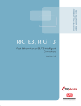
Applications
When used as a short range modem, ASM-40CD establishes a communication link
with an identical module installed in a remote LRS-24 hub, or an ASM-40/R in a
remote ASM-MN-214 hub, or with a standalone ASM-40 modem on the other end
of the line. A typical system application for ASM-40CD units, mounted in an
LRS-24 hub, is illustrated in Figure 1-1.
Central Site
Remote Site
V.35
(256 kbps)
LRS-24
2048 kbps
V.35
(256 kbps)
ASM-40
Public
Network
ASM-40CD
Router
V.35
(256 kbps)
2048 kbps
ASM-40
Router
RADview
Management
Station
Figure 1-1. Typical ASM-40CD Application
ASM-40CD Ver. 1.0
Overview
1-1
Chapter 1 Introduction
Installation and Operation Manual
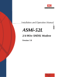
Figure 1-2 shows a power feeding application, where ASM-40CD/P card receives
the feed voltage from a standalone power supply unit, LRS-PS-FEED, connected
to the LRS-24 modem rack and supplies the voltage to two RPT repeaters.
Central Site
Remote Power Feeding
Remote Site
LRS-24
RPT
RPT
ASM-40
Router
RPT
RPT
ASM-40
Router
PCM
ASM-40CD/P
LRS-PS-FEED
Up to 4 km (2.4 miles)
Figure 1-2. ASM-40CD/P Providing Remote Power Feed to Repeaters
Features
ASM-40CD offers selectable data rates from 32 kbps to 2048 kbps, and
automatic rate detection in external mode for tail-end applications.
DTE Interface
The ASM-40CD DTE interface is provided using the appropriate interface module:
•
LRSI-F-5 for V.24/RS-232 (64 kbps), V.35, X.21, RS-530, and V.36 interfaces
(via adapter cables)
•
LRSI-F-14 for IR-ETH (Ethernet bridge) or IR-ETH/QN (Ethernet/Fast Ethernet
bridge with VLAN support).
Management
Full management of the local unit from an ASCII terminal or by a Unix HPOV
application via the LRS-24 Ethernet segment is available. Simultaneous control
and monitoring of local units is available without any impact or interference to
the user data being transmitted.
Diagnostics
ASM-40CD has real-time alarms indicating status of local and remote units.
ASM-40CD has V.54 diagnostic capabilities (local analog, remote digital and local
digital loopbacks) and an internal pseudo-random test pattern (511-bit) in
accordance with the ITU V.52 standard.
1-2
Overview
ASM-40CD Ver. 1.0
Installation and Operation Manual
Chapter 1 Introduction
Remote Power Feeding
The phantom current option for ASM-40CD provides a connection from an
internal current supply to external G.703 repeaters (RPT-I, RPT-O) through the
line. A standalone power supply, LRS-PS-FEED, serves as a power feeding source
for this internal current supply, and must be ordered separately.
The LRS-PS-FEED is connected to the LRS-24 hub AC power supply interface
module, LRSI-F-PSP/230/115. This interface module connects the feeding voltage
to all the modules installed in the LRS-24. The phantom current is 50 mA.
1.2
Physical Description
Figure 1-3. ASM-40CD Card
The ASM-40CD front panel consists of LEDs, two fastening screws, and two
handles for removing the card from the hub.
ASM-40CD front panel LEDs indicate module and system status with respect to
transmitted data, signaling and serviceability (see Figure 1-3).
ASM-40CD couples to the LRS-24 hub backplane by three connectors, and
couples to the digital interface card by four card connectors (see Figure 1-4).
ASM-40CD Ver. 1.0
Physical Description
1-3
Chapter 1 Introduction
Installation and Operation Manual
POWER
TD2
RD2
RTS2
TD1
P10
RD1
RTS1
DCD1
DCD2
SYNC LOSS2
TEST2
SYNC LOSS1
F3
TEST1
P11
F5
F4
F6
F1
P12
F2
Figure 1-4. ASM-40CD Card Layout
Six fuses are used in ASM-40CD, with four on the backboard (see Figure 1-4).
Table 1-1 describes each fuse.
Table 1-1. Fuse Data
1-4
Physical Description
Name
Function
F1, F2
1A for the +135V phantom power supply line
F3
1A for the –5V power supply
F4
1A for the +5V power supply
F5
500 mA for phantom of modem 1 power supply
F6
500 mA for phantom of modem 2 power supply
ASM-40CD Ver. 1.0
Installation and Operation Manual
1.3
Chapter 1 Introduction
Functional Description
Block Diagram
Figure 1-5 illustrates the circuits required for setting the correct configuration of
the modem.
TD
RD
TC & RC
NRZ
Interface
Line Driver
HDB3
AMI
B8ZS
Encoder/Decoder
FIFOs
BERT
V.54 Circuit
AGC, Equalizer
Clock Recovery
EXT CLK
Transmit Clock
CPU
POWER
PLL
VCXO
LEDs
External Clock
Receive Clock
Figure 1-5. ASM-40CD Block Diagram
CPU
The CPU runs the communication with the hub common logic module (CM-2),
using an internal protocol via lines LRS-TX and LRS-RX on the LRS-24 backplane. It
also drives the LEDs for indicating status and failure conditions.
Power Supply
The power supply filters the ±5V outputs from the LRS-24 power supply.
Timing Generator
ASM-40CD utilizes a PLL, VCXO circuit.
ASM-40CD transmits data to the line at one of four selectable baud rates. This
feature enables ASM-40CD to be used as a rate converter:
•
2048 kbps – transmits data at rates of 32, 64, 128, 256, 512, 1024 and
2048 kbps
•
1536 kbps – transmits data at rates of 192, 384, 768 and 1536 kbps
•
1544 kbps – transmits data rates at 1544 kbps
•
1920 kbps – transmits data at rates of 1920 kbps.
Transmit and receive timing may originate from the following sources:
ASM-40CD Ver. 1.0
•
Internally
•
Externally, from the data terminal
•
Externally, from the receive signal (see Figure 1-6).
Functional Description
1-5
Chapter 1 Introduction
Installation and Operation Manual
The setting of XMT clock depends on:
•
Internal clock – from the modem’s internal crystal oscillator
•
External clock – from the DTE
•
Receive clock – recovered from received signal.
Internal FIFOs with PLL provide jitter attenuation and/or phase difference
correction either from the incoming analog signal (line side) or from the external
clock on the DTE side.
Encoder/Decoder
Provides the conversion from NRZ to HDB3, AMI or B87S on the transmission side
and back to NRZ on the receive side.
Line Driver
Provides a three-level alternate mark inversion signal according to ITU G.703
standard.
Receiver
Provides the receive signal for the clock and data recovery circuitry.
NRZ Interface
On the digital side, provides as interface choice of V. 24, V.35, V36, X.21, RS-530,
IR-ETH (Ethernet bridge) or IR-ETH/QN (Ethernet/Fast Ethernet bridge with VLAN
support).
Diagnostics
ASM-40CD provides remote digital loopback, local digital loopback and local
analog loopback diagnostics in compliance with the V.54 standard.
The local analog and remote digital loopbacks can be activated via the DTE
interface:
•
V.35 – pins “h” and “j”
•
V.24 and RS-530 – pins 18 and 21.
Test Pattern Generator and Receiver (ITU V.52)
This feature allows for quick and easy testing of the local modem as well as the
communication link. When the BERT command is activated, the circuit sends and
checks a standard 511-bit pseudo random pattern. If errors are encountered, the
ERR indicator lights up.
The test can be carried out in local loopback, in remote digital loopback or in
normal point-to-point operation opposite a remote ASM-40 modem (press the
PATT pushbutton on the remote unit or connect a bit error rate tester which uses
the standard 511-bit pattern).
1-6
Functional Description
ASM-40CD Ver. 1.0
Installation and Operation Manual
Chapter 1 Introduction
Internal, Receive
External
TD
XMT
FIFO
Clock and Data
TX
RC
PLL
TC
External
EXT CLK
Internal
Crystal
Internal
Receive
RCV
FIFO
RD
Clock and Data
RX
Figure 1-6. Clock Diagram
ASM-40
ASM-40
INT
TXD
TX
RCV
TX
TX
TXD
TX
PLL
TC & RC
Clock Recovery
TC & RC
FIFO
RXD
RC
RX
FIFO
RX
RX
FIFO
RXD
Clock Recovery
ASM-40
TXD
EXT CLK
RX
TD
ASM-40
EXT
RCV
TX
TX
TXD
PLL
TC & RC
TC & RC
Clock Recovery
FIFO
RD
RXD
RC
RX
RX
FIFO
RXD
Clock Recovery
Figure 1-7. Clock Configuration
Management
ASM-40CD is managed by an ASCII terminal or an SNMP management tool via the
RS-232 port and the Ethernet port of the LRS-24 common logic card (CM-2).
Operation of the module from an ASCII terminal is detailed in Chapter 3.
Configurable Parameters
Table 1-2 lists the ASM-40CD parameters that are configurable from an external
management tool.
ASM-40CD Ver. 1.0
Functional Description
1-7
Chapter 1 Introduction
Installation and Operation Manual
Table 1-2. ASM-40CD Configurable Parameters
Parameter
Function
Data rate
Transmission data rate (in kbps) of the local modem
Clock source
Clock source of the local modem
Loop & BERT
Type of loopback and BERT
LED test
Test of front panel LEDs
Local loopback
Enable/disable local loopback (LLB) from DTE
Remote loopback
Enable/disable remote loopback (RLB) from DTE
Line code
AMI, HDB3, B8ZS
Transmit impedance
120Ω, 100Ω or 75Ω
Carrier control
On, Control
Phantom option
On, Off
Detailed instructions for configuring these parameters from an ASCII terminal are
provided in Chapter 3 and Appendix D.
1.4
Line Interface
Technical Specifications
Number of Channels
Two
Type
4-wire unconditioned dedicated line (two twisted pairs)
Coding
User-selectable to HDB3, AMI or B8ZS
Framing
Unframed
Transmit Level
According to G.703
Baud Rates
2048, 1544, 1536, or 1920 kbps
Impedance
For 2048 and 1920 kbps:
• 75Ω, unbalanced
• 120Ω, balanced
1544 and 1536 kbps:
• 100Ω, balanced
1-8
Return Loss
Better than 12 dB
Attenuation
Up to 40 dB for approximate range up to 1.75 km (1 mile)
Connector
RJ-45
Technical Specifications
ASM-40CD Ver. 1.0
Installation and Operation Manual
DTE Interface
Chapter 1 Introduction
Type
V.24, V.35, V.36, X.21, RS-530, IR-ETH
Data Rate
32, 64, 128, 192, 256, 384, 512, 768, 1024, 1536,
1544, 1920 and 2048 kbps
Interface Modules
• LRSI-F/B-5 – V.24, V.35, V.36, X.21, RS-530 via
SCSI-26 female connectors
• LRSI-F/B-14 – IR-ETH, IR-ETH/QN via RJ-45 connectors
Timing
Transmit and
Receive
• Internal – From on-board oscillator
• External – From the DTE
• Receive – Derived from the receive signal
Indicators
POWER ((green)
ON – ASM-40CD is powered
TD (yellow)
ON – Steady SPACE is transmitted
Blinks – Data is transmitted
RD (yellow)
ON – Steady SPACE is received
Blinks – Data is received
Diagnostics
RTS (yellow)
ON – DTE activates Request-to-Send
DCD (yellow)
ON – A valid receive line signal is present
SYNC LOS (red)
ON – There is no synchronization between the two
modems
TEST (red)
A test is active
ERR (red)
ON – The internal BER tester detects an error in the
received data or sync loss in BER test
Loopbacks
ITU V.54:
• Local analog loopback, activated via terminal, SNMP
management tool or by the DTE interface signal
• Remote digital loopback, activated via terminal, SNMP
management tool or by the DTE interface signal
• Local digital loopback, activated via terminal or SNMP
management tool
BERT
Physical
ASM-40CD Ver. 1.0
Built-in pattern generator and tester activated from
terminal, complies with ITU V.52
Up to 12 ASM-40CD modem cards can be
accommodated per LRS-24 hub
Technical Specifications
1-9
Chapter 1 Introduction
Power Supply
Environment
1-10
Installation and Operation Manual
Voltage
±5V
Power Consumption
3.5W max.
Temperature
0–50°C / 32–122°F
Humidity
Up to 90%, non–condensing
Technical Specifications
ASM-40CD Ver. 1.0
Chapter 2
Installation and Operation
This chapter provides information for:
•
Installation of the ASM-40CD module
•
Installation of the interface module
•
Operating the ASM-40CD modem.
Chapter 3 presents information on configuring the system using an ASCII
terminal.
If a malfunction appears, refer to Chapter 4 for troubleshooting.
The information presented in this chapter supplements the general instructions
for installation and operation of the LRS-24 hub. Refer to LRS-24 installation and
operation manual for further information.
2.1
Introduction
To complete the installation of ASM-40CD, perform the following (in the given
order):
1. Install the card into the LRS-24 chassis.
2. Install the interface module into the LRS-24 chassis.
3. Connect the appropriate cable to the interface module.
4. Power the modem up.
Warning
No internal settings, adjustment, maintenance, and repairs may be performed by
either the operator or the user; such activities may be performed only by a skilled
technician who is aware of the hazards involved.
Always observe standard safety precautions during the installation, operation,
and maintenance of this product.
2.2
Package Contents
The ASM-40CD package contains:
ASM-40CD Ver. 1.0
•
ASM-40CD modem card
•
Matching interface module
Package Contents
2-1
Chapter 2 Installation and Operation
•
Installation and Operation Manual
Splitter cable for connecting an interface module to the appropriate DTE:
V.24 – CBL-SCS26/V24
RS-530 – CBL-SCS26/RS530
V.35 – CBL-SCS26/V35
X.21 – CBL-SCS26/X21
V.36 – CBL-SCS26/V36
•
Last Mile Access and Intelligent Modems CD.
2.3
Installing the ASM-40CD Card
Installing the Card in the Chassis
To install ASM-40CD into the chassis:
1. Insert the ASM-40CD card into the assigned I/O slot of the LRS-24 enclosure,
as described in the system installation plan (see LRS-24 installation and
operation manual).
2. Tighten the screws that secure the ASM-40CD module to the LRS-24 frame,
for proper grounding of the module panel. The PCB layout of the ASM-40CD
card is shown in Figure 2-1.
POWER
TD2
RD2
RTS2
TD1
P10
Digital Interface1
RD1
RTS1
DCD1
DCD2
SYNC LOSS2
TEST2
SYNC LOSS1
TEST1
F3
Digital Interface2
P11
F5
F4
F6
F1
F2
Fuses F5, F6 on Backplane
P12
Fuses F3, F4 on Backplane
Figure 2-1. Diagram of ASM-40CD PCB
2-2
Installing the ASM-40CD Card
ASM-40CD Ver. 1.0
Installation and Operation Manual
Chapter 2 Installation and Operation
Table 2-1. ASM-40CD Fuses
Fuse
Function
F1, F2
1A for the 135V phantom power supply line
F3
1A for the -5V power supply
F4
1A for the +5V power supply
F5
500 mA for phantom of the modem 1 power supply
F6
500 mA for phantom of the modem 2 power supply
Table 2-2 describes the backplane connectors, shown in Figure 2-1.
Table 2-2. Backplane Connectors
2.4
Connector
Function
Use
P10
Data
Carrying data and signaling to/from the
interface module
P11
Control
Coupling ASM-40CD module to the hub
control module
P12
Power
Supplying +5V and –5V from the hub
power supply module
Installing the Interface Module
Interface Module Inspection
Check that the supplied interface module meets the physical and electrical
interface requirements of the installation site, according to Table 2-3. The
interface modules are:
•
LRSI-F-5 – V.24/RS-232 (64 kbps), V.35, X.21, RS-530 and V.36 interfaces
(via adapter cables), see Figure 2-2.
•
LRSI-F-14 – IR-ETH, IR-ETH/QN, see Figure 2-3.
For a more detailed description of the IR-ETH and IR-ETH/QN interface modules,
see Appendix A and Appendix B.
Note
ASM-40CD Ver. 1.0
LRSI-F-xx interface modules are placed in the top section of the LRS-24F chassis;
LRSI-B-xx interface modules are placed in the back section of the LRS-24B
chassis.
Installing the Interface Module
2-3
Chapter 2 Installation and Operation
Installation and Operation Manual
Table 2-3. Interface Module Connections for ASM-40CD
Interface
Module
ITU-T
DCE Connector
Line Connector
V.35
CBL-SCS26/V35
V.36
LRSI-F-5
LRSI-F-14
RAD DTE Cable
CBL-SCS26/V36
2 × SCSI-26,
female
RS-530
2 × RJ-45
CBL-SCS26/RS530
V.24
CBL-SCS26/V24
X.21
CBL-SCS26/X21
IR-ETH
2 × RJ-45
2 × RJ-45
IR-ETH/QN
LRSI-F-5
1
2
LRSI-F-14
1
L
I
N
E
2
L
I
N
E
DCE-1
DCE-1
DCE-1 DCE-2
Figure 2-2. LRSI-F-5
2-4
Installing the Interface Module
Figure 2-3. LRSI-F-14
ASM-40CD Ver. 1.0
Installation and Operation Manual
Chapter 2 Installation and Operation
Setting Internal Jumpers
The DTE1 and DTE2 jumpers serve for selection of the serial interface type
(see Figure 2-4).
F1
F2
F3
J5
F4
F5
F6
F7
F8
P1
P2
P3
P4
P5
P6
DTE1
DTE2
Figure 2-4. Interface Module LRSI-F-5 Jumpers and Fuses
To select the serial interface type:
•
V.24, X.21, RS-530 and V.36 – Set the DTE1 and DTE2 jumpers over the P1
and P2 pins.
•
V.35 – Set the DTE1 and DTE2 jumpers over the P2 and P3 pins.
Installing the Interface Module into the Chassis
To install the interface module in the LRS-24 chassis:
1. Insert the interface module into the upper section above the ASM-40CD
module of the LRS-24F chassis, or back section of the LRS-24B chassis.
2. Fasten two front panel screws to secure the module to the LRS-24 frame for
proper grounding.
2.5
Interfaces and Connections
The ASM-40CD modem is connected to the line and DTE via the interface module.
Identify the necessary cables for the interface module you have installed and
prepare the line and DCE cables.
Use Table 2-4 to prepare the line cable.
ASM-40CD Ver. 1.0
Interfaces and Connections
2-5
Chapter 2 Installation and Operation
Installation and Operation Manual
Connecting the Line and DTE
To connect the line and DCE cables to the interface module:
1. Connect the line and DCE cables to the appropriate interface module
connectors.
2. Use the side screws of the DCE cable connector to fasten the cable to the
interface module DCE connector.
Table 2-4. RJ-45 Line Connector Pinout
Pin
ID
Function
Direction
1
TTIP
Transmit TIP rail
Output
2
TRING
Transmit RING rail
Output
4
RTIP
Receive TIP rail
Input
5
RRING
Receive RING rail
Input
3, 6, 7, 8
–
–
–
2.6
Operating the ASM-40CD
Front Panel Indicators
Figure 2-5 shows the front panel LEDs of the ASM-40CD module. Table 2-5 lists
the functions of the indicators located on the ASM-40CD front panel.
2-6
Operating the ASM-40CD
ASM-40CD Ver. 1.0
Installation and Operation Manual
Chapter 2 Installation and Operation
Table 2-5. ASM-40CD LEDs
ID
Color
State
Indication
POWER
Green
On
Power is On
Off
Power is Off
On
Steady SPACE is transmitted
Blinks
Data is transmitted
On
Steady SPACE is received
Blinks
Data is received
TD1
TD2
On
The Request-To-Send signal is sent
from the DTE
RD1
RD2
TD
RD
RTS
DCD
Yellow
Yellow
Yellow
Yellow
SYNC
LOSS
Red
TEST
Red
ERR
Red
On
A valid signal exists on the receive
line
On
Loss of synchronization
Off
Synchronization has been achieved
On
A loopback mode is set or an
internal BERT is activated
On
Blinks
An alarm is initiated or sync loss in
BER tests
POWER
RTS1 RTS2
DCD1 DCD2
SYNC LOSS
1
2
TEST
An error is detected in BER tests
1
2
ERR1 ERR2
ASM-40CD
Figure 2-5. ASM-40CD LEDs
ASM-40CD Ver. 1.0
Operating the ASM-40CD
2-7
Chapter 2 Installation and Operation
Installation and Operation Manual
Powering ASM-40CD Up
To power ASM-40CD up:
•
Turn on the LRS-24 modem racks on both sides of the line.
After power-up, all LEDs are lit up for 3 seconds while the CPU initiates
the ASM-40CD module.
After synchronization between the two modems has been achieved, the
ASM-40CD module assumes the normal state according to the LED
indications in Table 2-6.
Normal Operation
After power-up the LEDs should assume the states as shown in Table 2-6. For
other LED indications, see Table 2-5.
Table 2-6. Normal LED Indications
2-8
ID
Color
State
Notes
POWER
Green
ON
ASM-40CD is powered-up
TD
Yellow
–
TD LED state depends on local DTE transmission
RD
Yellow
–
RD LED depends on remote DTE transmission
RTS
Yellow
–
Indicates RTS from DTE
DCD
Yellow
ON
Indicates signal detection on the line
SYNC LOSS
Red
–
Loss of synchronization
TEST
Red
OFF
ERR
Red
OFF
Operating the ASM-40CD
If ERR LED is ON – check alarm buffer to determine
problem
ASM-40CD Ver. 1.0
Chapter 3
Configuration
This chapter describes how to configure the ASM-40CD modem installed in the
LRS-24 hub using an ASCII terminal. It includes sections on:
•
Initiating an ASCII terminal session
•
Entering commands
•
Configuring the modem.
3.1
Introduction
The terminal is used to configure, monitor and perform diagnostic tests for the
LRS-24 hub and modems installed in it. Specific screens are used for each of
these management operations.
The ASCII terminal operations for the LRS-24 hub are described in the LRS-24
installation and operation manual. That manual provides instructions for:
•
Accessing various terminal screens
•
Entering control parameter options
•
LRS-24 management operations.
The LRS-24 management screens available through the ASCII terminal handle the
hub functions for:
•
IP management network
•
LRS-24 chassis status.
The LRS-24 hub screens also provide information on modems installed in the
chassis and their alarm status (see Table 3-1).
Note
ASM-40CD Ver. 1.0
For SNMP RADview operation, refer to RADview User’s manual.
Introduction
3-1
Chapter 3 Configuration
Installation and Operation Manual
Table 3-1. LRS-24 Screens
3.2
Screen
Indication
LRS-24 cards
Indicate slot number in which the modem is installed,
and the type of SNMP management associated with the
module, via either on-board agent (SMOD) or CM-2
agent (IMOD). The ASM-40CD module is IMOD type.
Hub alarm
Indicates whether a modem alarm is active or not. The
active alarm associated with a specific modem is shown
in the MODEM ALARMS STATUS screen. For details
regarding the ASM-40CD alarms, see Alarm Buffer and
Using Alarm Messages in Chapter 4.
Hub log file
Indicates time and data of events, such as modem
removal from or insertion to the hub.
Initiating an ASCII Terminal Session
To enable an ASCII terminal session:
1. Connect the terminal to the CM-2 RS-232 connector of the LRS-24 hub.
2. Power-up the CM-2 module.
The opening screen shown in Figure 3-1 appears followed by the
Cm2> prompt.
L
L
L
L
LLLL
RRRR
R R
RRRR
R R
R R
SSS
S
SS
---S
SSS
222
2
2
2
2
22222
4
4
4
4
444444
4
4
RAD DATA COMMUNICATIONS
Figure 3-1. LRS-24 Terminal Session Opening Screen
3.3
Entering Commands
The commands listed in Table 3-2 enable you to access ASM-40CD screens. After
the CM-2> prompt appears, type one of these commands to to view the desired
screen. In the command phrases indicated below, nn denotes the number of the
slot in which the ASM-40CD module is installed, where nn = 1 through 12.
3-2
Entering Commands
ASM-40CD Ver. 1.0
Installation and Operation Manual
Chapter 3 Configuration
Table 3-2. Screen Access Commands
Command
Function
NODEnn DEF OPR
Setting operational parameters. This screen is needed to
switch control or to load configurable parameters from one
modem to the other.
NODEnn DEF PRM
Setting data rate and timing of both modems
NODEnn DSP STT
Viewing types of both digital and fiber optic interfaces and LED
indications
NODEnn DEF TST
Invoking loopback connections, BER tests, and LED test
NODEnn DSP ALT
Viewing modem alarm messages and status
NODEnn DSP LOG
Viewing list of timed events for the modem
See Appendix D for a further explanation of the ASM-40CD commands.
Parameters shown on the ASM-40CD screens are of the read or write type.
Navigating the Menu
The operator can change write parameters to using the keys described in
Table 3-3.
Table 3-3. Keys to Change Screen Write Parameters
ASM-40CD Ver. 1.0
Key
Action
<Tab>
Moving from field to field. Pressing <Tab> in the last field brings the
cursor back to the first field on the screen
<F> or <U>
Viewing the next parameter option in the list
<B> or <D>
Viewing the previous parameter option in the list
<Enter>
Saving selected parameter options and exit the screen
<Esc>
Exiting the screen without saving selected parameter options
Entering Commands
3-3
Chapter 3 Configuration
3.4
Installation and Operation Manual
Default Factory Settings
The factory settings are listed in Table 3-4.
Table 3-4. Default Factory Settings
3.5
Parameter
Factory Setting
Data Rate
256 kbps
Clock Source
INT–RCV
Input Impedance
120
Carrier Control
On
Line Coding
HDB3
Loop & BERT
Cancel
Local Loopback
Disable
Remote Loopback
Disable
Remote Dig Enable
Off
Configuring the Modem
You can configure the modem for your specific application.
To configure the modem:
1. Type: NODEnn DEF PRM<Enter>.
The Modem Setup menu appears.
2. Move the cursor to the Select Modem field by pressing <Tab> and select the
local modem that you intend to configure by pressing <F> or <B>.
3. Move the cursor to the DATA RATE field by pressing <Tab> and select the
desired transmission rate.
4. Move the cursor to the CLOCK SOURCE field by pressing <Tab> and select the
clock source for the local and remote modems.
5. Move the cursor to the INPUT IMPEDANCE field by pressing <Tab> and select
the line impedance for the E1 line (if applicable).
Note
If you choose 75Ω, the Impedance (input and output) will be 75Ω; however, for
an unbalanced connection, use an adapter cable (UTP for unbalanced). The
adapter cable is not supplied by RAD.
6. Move the cursor to the LINE CODING field by pressing <Tab> and select the
G.703 line coding.
Refer to Appendix D for further information on commands.
3-4
Configuring the Modem
ASM-40CD Ver. 1.0
Chapter 4
Troubleshooting and
Diagnostics
This chapter discusses:
•
Types of loopback tests
•
Internal BERT operation
•
Setting loopback, BER, and LED tests
•
Viewing alarm status
•
Viewing alarm buffer messages
•
Troubleshooting.
All diagnostics options can be implemented from an ASCII terminal or from an
SNMP management tool. The LLB and REM loopbacks can also be initiated from
the DTE via dedicated pins of the DCE connector. These diagnostic approaches
can also be used in combination. For example, the BERT circuit test pattern can
be run on a path determined by one of the loopback connections and then
examine the alarm buffer messages for any transmission error or configuration
mismatch.
4.1
Loopback Tests
Three loopback connections apply to a transmission system consisting of an
ASM-40CD local module and an ASM-40 remote unit.
ASM-40CD Ver. 1.0
•
Local analog loopback – The analog transmit signal from the local unit
transmitter is looped back to the local unit receiver. The loopback tests the
local ASM-40CD modem, the local DTE and the connections between them.
The loopback is set from the local DTE via the LLB control line (see
Figure 4-1).
•
Local digital loopback – The digital receive signal is looped back in the local
ASM-40CD towards the line. The loopback tests the local ASM-40CD, the
remote DTE and the line between them (see Figure 4-3).
•
Remote digital loopback – The digital receive signal is looped back in the
remote ASM-40 towards the line. The loopback tests the local ASM-40CD, the
remote ASM-40 and the line between them. The loopback is set from the
local ASM-40CD or from the local DTE via the RLB control line (see
Figure 4-2).
Loopback Tests
4-1
Chapter 4 Troubleshooting and Diagnostics
Installation and Operation Manual
While a loopback connection is set, the TEST LED is lit up on the front panel of
both local and remote units.
Activating Loopback Tests
V.54 loopback connections are set from:
•
•
An ASCII terminal or from an SNMP management tool
Local or remote DTE (except for the X.21 and Ethernet digital interfaces).
For V.54 loopback settings using an ASCII terminal connected to the local unit,
refer to Section 4.3.
Running Loopback Tests
To run a loopback test:
•
Configure the modem to enable tests (see Section 4.3).
Check any alarms and alarm messages (see Section 4.4).
Loopback tests are best performed in the order presented here.
For details on troubleshooting ASM-40CD malfunctions using loopback tests, see
Using Loopbacks for Troubleshooting.
Before running the loopback tests:
• Verify that the data terminal is operating properly and can be used for a test.
• Do not perform tests with faulty equipment.
Ensure that all units are powered on and are configured correctly.
Local Analog Loopback (LLB)
The local analog loopback (LLB) checks the performance of the local ASM-40CD
modem, the local data terminal, and the connections between them
(see Figure 4-1).
LLB is activated from the DTE, RADview, or an ASCII terminal. When LLB is
initiated, the TEST LED lights up.
4-2
Loopback Tests
ASM-40CD Ver. 1.0
Installation and Operation Manual
Chapter 4 Troubleshooting and Diagnostics
ASM-40CD
Data
XMT
DTE 1
Clock
RCV
Data
Data
XMT
Clock
DTE 2
Clock
RCV
Data
Figure 4-1. ASM-40CD Local Analog Loopback (LLB)
After testing the DTE connection, repeat the LLB test using BERT equipment. If
the BER test indicates an error-free data stream, but the test using DTE indicates
a fault, verify that the cable between the DTE and ASM-40CD is correctly
connected. If the problem persists follow the DTE manufacturer’s test
procedures.
To pinpoint a line problem, perform the LLB loopback at the opposite end. If both
LLB tests are error-free, the fault is in the line that is part of the LRSI-F-XX
interface modules.
After completing the test or correcting the fault, deactivate the LLB loopback.
Remote Digital Loopback (RLB)
The remote digital loopback (RLB) tests the performance of each local ASM-40CD
modem with its respective remote ASM-40 unit, as well as the line link. The
remote digital loopback sets a loop at the remote ASM-40 modem from the
terminal coupled to the local unit.
ASM-40CD Ver. 1.0
Loopback Tests
4-3
Chapter 4 Troubleshooting and Diagnostics
Installation and Operation Manual
Figure 4-2. ASM-40CD Remote Digital Loopback (RLB)
RLB is activated from a local DTE, RADview, or an ASCII terminal. When running
this test the TEST LED on the front panel of both the local and remote units is lit
up.
If the RLB test indicates a fault, but the LLB was successful for both local and
remote modems, then the line or G.703 interface on either side of the line is not
functioning properly.
Local Digital Loopback (DIG)
Local digital loopback test (DIG) determines the performance of both local
ASM-40CD and remote ASM-40, as well as the line link. The DIG loopback sets a
loop at the local modem from the terminal that is completed through the remote
unit (see Figure 4-3). The local digital loopback path is similar to that of the
remote digital loopback initiated from the remote unit.
DIG is activated either from RADview or an ASCII terminal. When running this test
the TEST LED on the front panel of the local unit is lit up.
Figure 4-3. ASM-40CD Local Digital Loopback (DIG)
4-4
Loopback Tests
ASM-40CD Ver. 1.0
Installation and Operation Manual
4.2
Chapter 4 Troubleshooting and Diagnostics
Internal BERT Circuit Operation
ASM-40CD has a built-in BERT circuit consisting of a pattern generator and a
pattern tester. This circuit acts in conjunction with the V.54 diagnostic loops and
remote BERT to verify normal system operation and isolate faulty equipment in
the event of system failure. Each of the modems on the card has a separate BERT
circuit.
Activating the BER tester simultaneously activates the pattern generator, which
sends a 511-bit pattern according to the ITU V.52 standard.
If errors are detected by the BER tester, the ERR LED flashes or remains ON.
Figure 4-4 shows the data flow from the pattern generator to the pattern tester
in the local BERT circuit.
Figure 4-4. ASM-40CD BER System Test
4.3
Setting Loopback and BER Tests
The Modem Diagnostic menu (Figure 4-5) provides information on diagnostic
options and enables you to set loopback connections and to test the BER. The
BER can be evaluated over a portion or the entire transmission system, using
either the built-in BERT circuit or external equipment.
To initiate a loopback and BERT:
•
Type: NODEnn DEF TST <Enter>.
The Modem Diagnostic menu appears (see Figure 4-5).
Note
ASM-40CD Ver. 1.0
nn is slot number, from 1 to 12.
Setting Loopback and BER Tests
4-5
Chapter 4 Troubleshooting and Diagnostics
Installation and Operation Manual
MODEM DIAGNOSTIC
MODEM
DEFINE MODEM PORT NUMBER
MODEM STATUS
SELECT MODEM
LOOP & BERT
REMOTE DIG ENABLE
BERT RESULTS
LED TEST
LOCAL LOOP BACK
REMOTE LOOP BACK
REMOTE DIG
ENABLE TEST FROM REM MODEM
BERT ERR INJECTION
NAME
: ASM-40CD(m)
: 1
: MASTER PERMANENT
: MODEM 1 LOCAL
: CANCEL
LOOP TIMEOUT: N/A
: ENABLE
: 0.0 E- 00
: OFF
: DISABLE
: DISABLE
: OFF
: N/A
: N/A
Figure 4-5. Modem Diagnostic Screen
Bolded rows in Figure 4-5 indicate fields applicable to ASM-40CD and standalone
modems. Additional, non-bolded parameters listed on a screen apply to other
modems installed in the LRS-24 hub (see Table 4-1).
Note
Running a test automatically cancels a previous set of tests. For details regarding
loopback definitions and BER tests, refer to Section 4.1 and Section 4.2
respectively.
Table 4-1. Modem Diagnostic Menu Parameters
Parameter
Type
Function
Option
Option Indicates:
MODEM NAME
Read
Identifying the modem type
whose status is being viewed
or modified
ASM-40CD(M)
Master ASM-40CD
MODEM
STATUS
Read
Checking whether loopback
and BER tests can be invoked
from this screen
Master
Permanent
Modem controls its own test
routines, which can be invoked
from this screen
SELECT MODEM
Write
Selecting the test
transmission path in
conjunction with one of the
loopback fields
Modem 1
Local
Modem 2
Local
Loopback connection is set
relative to modem 1 or 2 of the
card installed in the LRS-24 hub
LOOP & BERT
Write
Activating a specific loopback
or BER testing
ANA
Local loopback is set in the local
unit
REM
Remote loopback is set in the
remote unit
ANA+ BERT
Local loopback is set in the local
unit and enable the pattern
generator and the pattern tester
of the built-in BERT circuit
REM+ BERT
Remote loopback is set in the
remote unit and enables the
built-in BERT circuit
4-6
Setting Loopback and BER Tests
ASM-40CD Ver. 1.0
Installation and Operation Manual
Parameter
Type
Function
Chapter 4 Troubleshooting and Diagnostics
Option
Option Indicates:
BERT
Built-in BERT circuit is enabled.
For BER testing, a 511-bit
pattern generator must also be
enabled in the remote DTE
CANCEL
Cancellation of one of the tests,
set above
DIG
Local digital loopback is set in
local modem
REMOTE DIG
Local DIG from the remote
modem
REMOTE DIG
ENABLE
Read
BERT RESULTS
Read
Viewing the BER results for
one of the tests performed
by the built-in BERT circuit
0.0E-0 to
9.9E-9
BER test result
LED TEST
Write
Testing front LEDs of
ASM-40CD or standalone
modem
ON
LEDs are turned on for a few
seconds
OFF
LEDs are not tested
Enables remote loopback
activation from the DTE
ENABLE
Enables remote loopback (RLB),
from the DTE
DISABLE
Disables DTE RLB signal
ENABLE
Enables local loopback (LLB),
from the DTE
DISABLE
Disables DTE LLB signal
ON
ASM-40CD activates a local
digital loopback when remote
modem initiates remote digital
loopback
OFF
ASM-40CD does not activate a
local digital loopback when
remote modem initiates remote
digital loopback
REMOTE
LOOPBACK
LOCAL
LOOPBACK
REMOTE DIG
Write
Write
Enables local loopback
activation from the DTE
Write
Enables reception of the
local digital loopback
activation patern from
remote modem, when it
activates a remote digital
loopback
4.4
Viewing Alarm Status
The Modem Alarm Status screen (Figure 4-6) enables viewing messages stored in
the Alarm Buffer of the ASM-40CD and remote modems. The screen also shows
synchronization loss and DTE loopback signaling states.
To view the Alarm Status:
•
Type: NODEnn DSP ALT<Enter>.
The screen shown in Figure 4-6 appears.
ASM-40CD Ver. 1.0
Viewing Alarm Status
4-7
Chapter 4 Troubleshooting and Diagnostics
Installation and Operation Manual
MODEM ALARM STATUS
MODEM NAME
DEFINE MODEM PORT NUMBER
SELECT MODEM
LINE DISCONNECT
REMOTE MODEM POWER OFF
TRANSMIT CARRIER
RECEIVE CARRIER
LLB BY DTE
RLB BY DTE
SYNC LOSS
CONFIGURATION MISMATCH
NVRAM FAILED
ILLEGAL EXTERNAL CLOCK SOURCE
NO MANAGEMENT LINK
NO MODEM PORT (IR)
NO FIBER INTERFACE
IR RATE MISMATCH
SELF TEST FAILED
XILINX FAILED
MINOR ALARM - AIS-ELEC
MAJOR ALARM - LINE DISCON.-ELEC
: ASM40CD(m)
: 1
: MODEM 1 LOCAL
: OFF
: OFF
: OFF
: OFF
: OFF
: OFF
: ON
: OFF
: OFF
: OFF
: ON
: ON
LAN NOT CONNECTED
: OFF
NO EXT CLK INPUT
: OFF
ILL. CLK-ERR
: OFF
OLD REM VERSION
: OFF
WRONG CONNECTION
: OFF
AIS-OPT
: OFF
LINE DISCON.-OPT
:
:
:
:
:
:
:
OFF
OFF
OFF
OFF
OFF
OFF
OFF
Figure 4-6. Modem Alarm Status Screen
Bolded rows in Figure 4-6 indicate fields applicable to ASM-40CD and standalone
modems. Additional, non-bolded parameters listed on a screen apply to other
modems installed in the LRS-24 hub.
The function and options available for each highlighted parameter or alarm
message are summarized in Table 4-2.
Table 4-2. Modem Alarm Status Screen
Parameter
Type
Function
Option
Option indicates
LLB BY DTE
Read
LLB comand was issued
by DTE
Modem 1 Local
Modem 2 Local
LLB
RLB BY DTE
Read
RLB comand was issued
by DTE
Modem 1 Local
Modem 2 Local
RLB
SYNC LOSS
Read
Viewing the alarm state
ON
Modems are not locked
OFF
Modems are locked
ON
A non-volatile RAM failure
was detected. The
NVRAM contains the
system configuration.
OFF
No NVRAM failure was
detected
NVRAM FAILED
4-8
Read
Viewing Alarm Status
Viewing the alarm state
ASM-40CD Ver. 1.0
Installation and Operation Manual
Chapter 4 Troubleshooting and Diagnostics
Parameter
Type
Function
Option
Option indicates
ILLEGAL EXTERNAL
CLOCK SOURCE
Read
Viewing the alarm state
ON
Rate of external clock
detected by the modem
is not supported, or there
is no external clock
OFF
No failure as mentioned
above is detected.
ON
Management channel
between the modems is
not active.
OFF
No failure as mentioned
above is detected.
ON
Digital interface card is
not installed on ASM40CD, or the installed
module is not applicable.
OFF
Warning has not been
activated
ON
FPGA has been loaded
incorrectly
OFF
Warning has not been
activated
NO MANAGEMENT
LINK
NO MODEM PORT (IR)
XILINX FAILED
Read
Read
Read
View the alarm state.
Viewing the alarm state
Viewing the alarm state
The information presented on the Modem Alarms Status screen is valid only if the
Stop Status Update parameter in the Modem Advanced Setup screen is set to
DISABLE. If this parameter is set to ENABLE, it will prevent ASM-40CD alarm states
from being reported to the CM-2.
4.5
Viewing Alarm Buffer Messages
The ASM-40CD alarm buffer stores system alarm records, which can be viewed on
either an ASCII terminal or an SNMP management tool. When one or more alarm
records appear in the buffer, the front panel ERR LED turns ON. After the alarm
buffer is cleared, the ERR LED is reset to OFF. Table 4-3 lists the types of
messages that can be stored in the ASM-40CD alarm buffer.
ASM-40CD Ver. 1.0
Viewing Alarm Buffer Messages
4-9
Chapter 4 Troubleshooting and Diagnostics
Installation and Operation Manual
Table 4-3. ASM-40CD Alarm Messages
Alarm Message
Indicates
SYNC LOSS
Line is disconnected
NO MANAGEMENT
Management channel is not available
FPGA FAILED
ASM-40CD data processor has been incorrectly loaded
NVRAM FAILED
Modem non-volatile RAM failed
NO MODEM PORT (IR)
Modem does not detect the digital interface
ILLEGAL EXTERNAL CLOCK
Detected clock rate is not supported by the modem
4.6
Troubleshooting
ASM-40CD is designed to facilitate identifying and correcting system failures that
preclude normal modem operation. This section lists some possible failures in
ASM-40CD function, and describes their symptoms and the required corrective
actions.
Using LEDs
Many malfunctions or system failures can be detected through changes in the
state of the ASM-40CD front panel LEDs (described in Chapter 2). Table 4-4 lists
changes in the status of some LEDs that indicate malfunctions, and the
appropriate corrective actions.
Table 4-4. Troubleshooting Using LEDs
Symptom
Malfunction
Corrective Action
Power LED is Off
Blown fuse, +5V or -5V
Replace the blown fuse
SYNC LOSS LED is On
Modem is not locked
DCD LED is Off
Line connection between
modems
Check line and line
connection between
modems
TX LED is Off
Modems are locked
(no information transfer)
Modem to DTE connection
Check connection between
modem and DTE
ERR LED is On
See Table 4-5
–
Using Alarm Messages
Some ASM-40CD malfunctions can be detected from a combination of alarm
messages and changes in the state of the front panel LEDs. Table 4-5 details a
number of alarm messages associated with ERR LEDs that indicate different
sources for system failures and the required corrective actions.
4-10
Troubleshooting
ASM-40CD Ver. 1.0
Installation and Operation Manual
Chapter 4 Troubleshooting and Diagnostics
Table 4-5. Troubleshooting Using Alarm Messages
Symptom – ERR LED is On
Basis for Malfunction
Corrective Action
SYNC LOSS alarm is stored in
the Alarm Buffer
The line between the
modems is not properly
connected
Verify and connect the line properly
Verify that the remote modem works with
the same bit rate
Verify that the CARR is On or RTS is On
NVRAM FAILED alarm is stored in
the Alarm Buffer
Hardware failure
Replace the unit
INTERFACE alarm is stored in the
Alarm Buffer
No digital interface, or a
digital interface which is
not supported by modem
Connect a DTE interface which is supported
by the modem
ILLEGAL EXT CLK alarm is stored
in the Alarm Buffer
There is no external clock,
or the external clock
frequency is not
supported by the modem
Verify that an external clock is connected to
the modem and its frequency is supported
by the modem
XILINX FAILED alarm is stored in
the Alarm Buffer
ASM-40CD hardware
failure
Replace the unit
Using Loopbacks for Troubleshooting
To solve a system transmission problem, set V.54 loopback connections and
check Alarm Buffer messages (see Section 4.5) in the sequence shown in
Figure 4-7, Figure 4-8, and Figure 4-9. Loopback tests are described in Section
4.1.
After completing the test or correcting the fault, deactivate the loopback. Notice
that the TEST LED turns off. Deactivate a loopback before setting another
loopback.
ASM-40CD Ver. 1.0
Troubleshooting
4-11
Chapter 4 Troubleshooting and Diagnostics
Installation and Operation Manual
Start
Set local ASM-40CD
to LLB
OK?
Yes
1
No
Local modem
‘No Interface’
alarm On?
Yes
Install a legal
digital interface
card
No
Repair DTE-modem
connection
No
Match DTE and
modem clock
types
No
Local DTE
to modem connection
OK?
Yes
Local DTE
and modem clock
types match?
Yes
Set local ASM-40CD
to LLB + BERT
Yes
OK?
Failure in local
digital interface.
Repair/replace
digital interface.
No
Failure in
local modem.
Repair/replace modem.
Figure 4-7. Troubleshooting Flowchart using V.54 Loopbacks
4-12
Troubleshooting
ASM-40CD Ver. 1.0
Installation and Operation Manual
Chapter 4 Troubleshooting and Diagnostics
1
Local ASM-40CD
modem and DTE
connection are OK
Set local
ASM-40CD
to RLB
Yes
OK?
2
No
Local
modem ‘Sync Loss’
alarm on?
No
Yes
Line is
connected properly?
No
Connect line
properly. Replace
line if necessary.
Yes
Match line
parameters
Figure 4-8. Troubleshooting Flowchart Using V.54 Loopbacks (Cont.)
Note
ASM-40CD Ver. 1.0
Parameters in the remote ASM-40 are changed manually via internal switches and
jumpers.
Troubleshooting
4-13
Chapter 4 Troubleshooting and Diagnostics
Installation and Operation Manual
2
Local ASM-40CD
modem and line
connection are OK
Set local ASM-40CD
to DIG
Yes
OK?
No
Set remote ASM40
to BERT (manually)
Yes
OK?
Failure in remote
digital interface.
Repair/replace
digital interface.
No
Failure in remote
modem.Repair/
replace modem.
End
Figure 4-9. Troubleshooting Flowchart Using V.54 Loopbacks (Cont.)
4-14
Troubleshooting
ASM-40CD Ver. 1.0
Appendix A
IR-ETH Ethernet Card
A.1
Introduction
The IR-ETH Ethernet card is a bridge that converts Ethernet electrical levels to
TTL levels and Ethernet protocol to HDLC protocol. It provides long distance
transmission and avoids the Ethernet collision limitation. It is mounted on the
ASM-40CD modem module, installed in the LRS-24 hub.
Typical Application
A typical application of the ASM-40CD module, on which the IR-ETH Ethernet card
is mounted, is shown in Figure A-1. The LAN connection is made by using the
LRSI-F-14 Interface module installed in the upper section of the LRS-24F chassis,
or LRSI-B-14 installed in the back section of the LRS-24B chassis.
Central Office
Customer Premises
LRS-24
ASM-40
ASM-40CD
ASM-40
RADview
Management
Station
Figure A-1. Typical Application of ASM-40CD with IR-ETH
ASM-40CD Ver. 1.0
Introduction
A-1
Appendix A IR-ETH Ethernet Card
Installation and Operation Manual
Physical Description
Figure A-2 shows the IR-ETH Ethernet card. Four connectors are provided to
connect the Ethernet card to the top of the main module card. The IR-ETH card
contains a LED and 4-section DIP switch.
4
3
2
1
Figure A-2. Location of DIP Switch and ERR LED on IR-ETH Ethernet Card
A.2
General
LAN
WAN
A-2
Technical Specifications
LAN Table
10,000 addresses
Filtering and
Forwarding
15,000 pps
Buffer
256 frames
Delay
1 frame
Standard
Conforms to IEEE 802.3/Ethernet
Data Rate
10 Mbps (20 Mbps 10BaseT FDX)
Protocol
HDLC
Data Rate
According to the modem transmission rate
Connector
RJ-45
Technical Specifications
ASM-40CD Ver. 1.0
Installation and Operation Manual
A.3
Appendix A IR-ETH Ethernet Card
Installation and Operation
This section describes:
•
Setting the IR-ETH DIP switch
•
Installing the IR-ETH board on the ASM-40CD modem
•
Installing LRSI-F-14 interface module.
Configuring IR-ETH
Configure the IR-ETH module by setting the DIP switch in accordance with
Table A-1.
Table A-1. DIP Switch Settings
Number
Switch
Description
Default
Setting
1
SQ/FD
ON Ethernet bridge operates in full duplex mode
OFF
OFFEthernet bridge operates in half duplex mode
2
CMP
ON Strips padding bits inserted in 64-byte frame
ON
OFFTransmits frames over WAN as is
3
FIL
ON Passes only frames destined for another LAN
OFF Disables LAN filter; passes all frames
transparently
4
Caution
–
OFF
Permanently set to OFF
The ASM-40CD and IR-ETH cards contain components sensitive to electrostatic
discharge (ESD). To prevent ESD damage, do not touch the module components
or connectors.
Installing the IR-ETH Card
To install the IR-ETH card:
1. Set the DIP switch on the IR-ETH Ethernet card according to Table A-1.
2. Press the IR-ETH Ethernet card (with connectors facing down) against the
ASM-40CD module connectors.
3. Fasten IR-ETH to the modem.
ASM-40CD Ver. 1.0
Installation and Operation
A-3
Appendix A IR-ETH Ethernet Card
Installation and Operation Manual
Installing the Interface Module
Check that the LRSI-F-14 interface module (or LRSI-B-14), shown in Figure A-3,
was supplied. The fuses are shown in Figure A-4.
LRSI-F-14
1
2
L
I
N
E
DCE-1
ACT
INT
DCE-2
Figure A-3. LRSI-F-14 Interface Module
Backplane Connector
F1
Line Connectors
F2
F3
F4
F5
F6
Ethernet Connectors
F8
F7
Figure A-4. LRSI-F-14 Interface Module Fuses
A-4
Installation and Operation
ASM-40CD Ver. 1.0
Installation and Operation Manual
Appendix A IR-ETH Ethernet Card
Installing the Hub
To install LRSI-F-14:
1. Insert the LRSI-F-14 module into the upper section of the LRS-24F chassis
above the ASM-40CD module, or into the back section of LRS-24B.
2. Fasten the screws to secure the module to the LRS-24 frame for proper
grounding of the module panel.
Connecting the LRSI-F-14 Module
Table A-2 lists the pinout of the DCE-1/DCE-2 connector of the LRSI-F-14
interface module.
Table A-2. DCE-1/DCE-2 Connector Pinout
Pin
ID
Function
Direction
1
Tx+
Transmit – positive lead
Output
2
Tx–
Transmit – negative lead
Output
3
Rx+
Receive – positive lead
Input
4, 5
–
Not connected
–
6
Rx–
Receive – negative lead
Input
7, 8
–
Not connected
–
When connecting LRSI-F-14 to the LAN, use a cross cable for connection to a port
that does not implement the crossover function internally. Otherwise, use a
straight cable.
Note
•
To ensure compliance with electromagnetic compatibility (EMC) requirements,
use only shielded cables when connecting the DTE ports to the LAN.
•
Hubs usually do implement the crossover function internally while NICs and
other devices do not.
LED Indicators
Table A-3 lists the IR-ETH LED indicators and describes their functions.
Table A-3. IR-ETH LED Indicators
ASM-40CD Ver. 1.0
LED Name
Description
Color
INT
ON – Good link integrity
Green
ACT
ON – Data is received from the Ethernet attached
segment or data is transmitted from the
modem to the Ethernet segment
Yellow
ERR
(on-board)
ON – LAN/WAN error
Red
Installation and Operation
A-5
Appendix A IR-ETH Ethernet Card
A-6
Installation and Operation
Installation and Operation Manual
ASM-40CD Ver. 1.0
Appendix B
IR-ETH/QN (IR-ETH/Q)
Interface Module
B.1
Introduction
The IR-ETH/QN interface module includes a high performance self-learning Fast
Ethernet bridge, which is connected to the LAN via a single 10BaseT or 100BaseT
port, operating in full or half duplex and providing simple and cost-effective
interconnection between 10/100BaseT LANs. The IR-ETH/QN interface module also
supports IEEE 802.1/P frames and IEEE 802.1/Q frames, enabling VLAN
applications.
The module automatically learns MAC addresses of the LAN to which it is connected.
Its LAN table stores up to 1,024 addresses with 5-minute automatic aging.
Filtering and forwarding is performed at the maximum theoretical rate of
150,000 packets per second (wire speed). The buffer with 0.512 Mbit SRAM can
hold 85 frames with a throughput latency of one frame. The forwarding of the
multicast messages from LAN to WAN can be disabled.
Note
ASM-40CD ordered with the IR-ETH/Q interface is supplied with the functionally
equivalent IR-ETH/QN interface.
B.2
Application
Figure B-1 shows a typical application of ASM-40CD operating opposite two
remote ASM-40 modems connected to the 100BaseT LANs.
ASM-40CD Ver. 1.0
Application
B-1
Appendix B IR-ETH/QN (IR-ETH/Q) Interface Module
Installation and Operation Manual
Central Office
Customer Premises
LRS-24
ASM-40
ASM-40CD
ASM-40
RADview
Management
Station
Figure B-1. Typical Application of ASM-40CD with IR-ETH/QN
B.3
Bridge
LAN
Technical Specifications
LAN Table
1,024 MAC addresses
Aging
5 minute, automatic
Filtering and
Forwarding Rate
150,000 packets per second
Buffer Size
85 frames
Delay
1 frame
Standard
IEEE 802.3/Ethernet V.2 (relevant parts), IEEE 802.1q
(relevant parts), 802.1p, 802.3x
Data Rate
• 10BaseT: 10 Mbps (20 Mbps in full duplex)
• 100BaseT: 100 Mbps (200 Mbps in full duplex)
Line Code
• 10BaseT: Manchester
• 100BaseT: MLT3
WAN
B-2
Connector
Shielded RJ-45 socket
Protocol
HDLC
Data Rate
According to the modem transmission rate
Technical Specifications
ASM-40CD Ver. 1.0
Installation and Operation Manual
B.4
Appendix B IR-ETH/QN (IR-ETH/Q) Interface Module
Installation and Operation
This section describes:
•
Setting the IR-ETH/QN DIP switches
•
Installing the IR-ETH/QN board on the ASM-40CD modem
•
Installing LRSI-F-14 interface module.
Configuring IR-ETH/QN
Configure the IR-ETH/QN module by setting the DIP switches SW1 and SW2 in
accordance with Figure B-2, Table B-1 and Table B-2.
Note
To make the changes effective, you have to remove the ASM-40CD module from
the LRS-24 chassis and insert it back again.
SW2
1. 100
2. AN
3. FDX
4. BPR
5. MUL
6. NC
ON
SW1
1. MDI
2. LC1
3. LC2
4. FLC
5. NC
6. NC
7. NC
8. NC
ON
Figure B-2. DIP Switch Locations on the IR-ETH/QN Module
Table B-1. DIP SW1 Switch Settings
Section
Name
Description
Possible Settings
Factory Setting
1
MDI
Enables or disables
automatic MDI/MDIX
crossover
ON – Automatic MDI/MDIX crossover is
enabled
OFF – Automatic MDI/MDIX crossover is
disabled
OFF
Note: Automatic MDI/MDIX crossover function is available only if the autonegotiation is enabled (see Table B2).
ASM-40CD Ver. 1.0
Installation and Operation
B-3
Appendix B IR-ETH/QN (IR-ETH/Q) Interface Module
Installation and Operation Manual
Section
Name
Description
Possible Settings
Factory Setting
2
LC1
–
Permanently set at the factory
OFF
3
LC2
–
Permanently set at the factory
ON
4
FLC
Enables or disables flow
control
ON – Flow control is enabled
ON
–
Permanently set at the factory
5-8
NC
Note
OFF – Flow control is disabled
OFF
Sections 2, 3, 5, 6, 7 and 8 of the SW1 DIP switch are factory-set and must not
be moved by the user.
Table B-2. DIP Switch SW2 Settings
Section
Name
Description
Possible Settings
Factory Setting
1
100
Selects the LAN speed
ON – LAN speed is set to 10 Mbps
OFF
OFF – LAN speed is set to 100 Mbps
2
3
AN
FDX
Controls the LAN
autonegotiation
ON – LAN autonegotiation is disabled
Selects the LAN mode
ON – LAN half duplex mode
OFF
OFF – LAN autonegotiation is enabled
OFF
OFF – LAN full duplex mode
4
BPR
Controls the backpressure
ON – Backpressure is enabled
OFF – Backpressure is disabled
5
6
MUL
NC
Notes
Controls LAN to WAN
multicasting
–
ON
OFF – Multicast messages from LAN to
WAN are blocked
ON – Multicast messages from LAN to
WAN are not blocked
ON
Permanently set at the factory
ON
• Section 6 of the SW2 DIP switch is factory-set and must not be moved by the
user.
• When autonegotiation is enabled, LAN speed and LAN mode are configured
automatically (sections 1 and 3 are disabled).
Installing the IR-ETH/QN Card
To install the IR-ETH/QN card:
1. Press the IR-ETH/QN Ethernet card (with connectors facing down) against the
ASM-40CD module connectors.
2. Fasten IR-ETH/QN to the modem.
B-4
Installation and Operation
ASM-40CD Ver. 1.0
Installation and Operation Manual
Appendix B IR-ETH/QN (IR-ETH/Q) Interface Module
Installing the Interface Module
Check that the LRSI-F-14 interface module (or LRSI-B-14), shown in Figure B-3,
was supplied. The fuses are shown in Figure B-4.
Note
Fuses F3 and F4 of the IR-ETH/QN module must have ratings of 5A if the
customer installs or replaces the module in the field. If they are not 5A they must
be replaced.
LRSI-F-14
1
2
L
I
N
E
DCE-1
ACT
INT
DCE-2
Figure B-3. LRSI-F-14 Front Panel
Backplane Connector
F1
Line Connectors
F2
F3
F4
F5
F6
Ethernet Connectors
F8
F7
Figure B-4. LRSI-F-14 Interface Module Fuses
ASM-40CD Ver. 1.0
Installation and Operation
B-5
Appendix B IR-ETH/QN (IR-ETH/Q) Interface Module
Installation and Operation Manual
Installing the Hub
To install LRSI-F-14:
1. Insert the LRSI-F-14 module into the upper section of the LRS-24F chassis
above the ASM-40CD module, or into the back section of LRS-24B.
2. Fasten the screws to secure the module to the LRS-24 frame for proper
grounding of the module panel.
Connecting the LRSI-F-14 Module
Table B-3 lists the pinout of the DCE-1/DCE-2 connector of the LRSI-F-14
interface module.
Table B-3. DCE-1/DCE-2 Connector Pinout
Pin
ID
Function
Direction
1
Tx+
Transmit – positive lead
Output
2
Tx–
Transmit – negative lead
Output
3
Rx+
Receive – positive lead
Input
4, 5
–
Not connected
–
6
Rx–
Receive – negative lead
Input
7, 8
–
Not connected
–
When connecting LRSI-F-14 to the LAN, use a cross cable for connection to a port
that does not implement the crossover function internally. Otherwise, use a
straight cable.
Note
Hubs usually do implement the crossover function internally while NICs and other
devices do not.
LED Indicators
Table B-4 lists the IR-ETH/QN rear panel LED indicators and describes their
functions.
Table B-4. LED Indicators
LED Name
Color
Description
Location
LINK
Green
ON – LAN link is ON
Connector
ACT
Yellow
ON or blinking – LAN is receiving data
Connector
B-6
Installation and Operation
ASM-40CD Ver. 1.0
Appendix C
Command List
This chapter lists:
•
Commands to access screens:
Modem advanced setup
Modem setup
Modem status
Modem log file
•
Screen parameters with their values and explanations.
C.1
Modem Advanced Setup
Setting Operational Parameters
The Modem Advanced Setup screen enables you to set the operational
parameters of ASM-40CD. When this screen appears, all parameters are set to
either the default or inactive state to prevent an unexpected modem response.
To configure the operational parameters:
•
Type NODEnn DEF OPR<Enter>.
The screen shown in Figure C-1 appears.
Note
nn = slot number, from 1 through 12.
MODEM ADVANCED SETUP
MODEM NAME
ASM-40CD Ver. 1.0
: ASM 40CD (m)
DEFINE MODULE PORT NUMBER
: 1
MODEM STATUS
: MASTER
SELECT MODEM
: MODEM 1 LOCAL
1) MODEM RESET
: DISABLE
2) STOP STATUS UPDATE
: DISABLE
3) CHANGE LOCAL MODEM STATUS
: MASTER
4) MANAGEMENT FROM REMOTE MODEM
: NO
5) MODEM MANAGEMENT LINK
: N/A
6) LOAD CONFIGURATION FROM
: N/A
7) I-TYPE (FAR_END MODEM type
: N/A
Modem Advanced Setup
C-1
Appendix C Command List
Installation and Operation Manual
Figure C-1. Modem Advanced Setup Screen
Bolded rows in Figure C-1 indicate parameters applicable to ASM-40CD and
standalone modems. Additional, non-bolded parameters listed on a screen apply
to other modems installed in the LRS-24 hub.
Table C-1 shows the operational parameters and options for ASM-40CD that can
be viewed and/or modified using this screen.
Table C-1. Modem Advanced Setup
Parameter
Type
Function
Option
Option Indicates
MODEM NAME
Read
Identifying the modem type
whose status is being viewed or
modified.
ASM-40CD(m)
Master ASM-40CD
MODEM
STATUS
Read
Viewing the modem
configuration control status
Master
Modem controls its own
configurable parameters
SELECT MODEM
Write
Selecting one of the two
modems on the card, whose
operational parameters you set
using this screen.
Modem 1
Local
Modem 2
Local
Operational Parameters will
be set for the modem
installed in the LRS-24 hub
STOP STATUS
UPDATE
Write
Controling status information
flow from the modem to
CM-2.
Disable
Disables flow of status
information from modem to
CM-2. This may occur when
CM-2 is required to service
other LRS-24 modems during
a state of alarm message
overflow.
Enable
Enables flow of status
information from modem to
CM-2.
C.2
Modem Setup
The Modem Setup screen enables you to set the transmission parameters of the
local and remote modems.
Setting Modem Transmission Parameters
To configure the modem transmission parameters:
•
Type: NODEnn DEF PRM<Enter>.
The screen shown in Figure C-2 appears.
Note
C-2
nn = slot number, from 1 through 12.
Modem Setup
ASM-40CD Ver. 1.0
Installation and Operation Manual
Appendix C Command List
MODEM SETUP
MODEM NAME
:
ASM 40CD (m)
DEFINE MODEM PORT NUMBER : 1
MODEM STATUS
: MASTER PERMANENT
SELECT MODEM
: MODEM 1 LOCAL
SYNC/ASYNC
: N/A
CHARACTER LENGTH
No. STOP BIT
: N/A
DATA RATE
PARITY
: N/A
CD SENSE
CLOCK SOURCE LOC/REM : L(INT) R(RCV)
EXT SOURCE : N/A
INTERFACE
: N/A
RTS/CTS DELAY(0:255)
RTS TO DCD
: N/A
DTR TO DSR
OUTPUT LEVEL
: N/A
INPUT LEVEL
OUTPUT IMPEDANCE
: N/A ohm
INPUT IMPEDANCE
CARRIER CONTROL
: ON
ERROR CORRECTION
RATE ADAPTION METHOD : N/A
AIS
LINE CODING
: HDB83
PHANTOM
T1 LINE LENGTH
: N/A
BRIDGING
: N/A
ETHERNET MODE
MASK SIGNAL STATUS
: DATA:NO
RTS:NO
TD:NO
RD:NO
DCD:NO
TEST:NO
ERR:NO
LOS:NO
: N/A
: 2048k
: N/A
PORT: N/A
: N/A
: N/A
: N/A
: 120 ohm
: N/A
: N/A
: OFF
: N/A
Figure C-2. Modem Setup Screen
Bolded rows in Figure C-2 indicate parameters applicable to ASM-40CD and
standalone modems. Additional, non-bolded parameters listed on a screen apply
to other modems installed in the LRS-24 hub.
Table C-2 explains the transmission parameters and options for ASM-40CD that
can be viewed and set using the Modem Setup screen. The Write fields can be
changed only if the Master configuration mode is indicated in the Modem Status
field.
Table C-2. Modem Setup Screen
Parameter
Type
Function
Options
Option Indicates
MODEM NAME
Read
Identifying the modem
type whose status is being
viewed or modified
ASM-40CD(m)
Master ASM-40CD
SELECT MODEM
Write
Selecting one of two
modems whose operational
parameters are set using
this screen.
Modem 1 Local
Modem 2 Local
Operational parameters will be set
for the modem installed in the LRS24 hub
DATA RATE
Write
Setting data rate
transmitted between
modems
CLOCK SOURCE
LOCAL/REMOTE
Write
Timing mode
ASM-40CD Ver. 1.0
Note: Clock mode of both
local and remote units
must be configured
manually.
32, 64, 128, 192, 256, 384, 512,
768, 1024, 1536, 1544, 1920, or
2048 kbps
L(INT), R(RCV)
Crystal of the local modem is the
clock source; remote modem is
synchronized to the clock extracted
from the receive signal
Modem Setup
C-3
Appendix C Command List
Parameter
Type
Installation and Operation Manual
Function
Options
Option Indicates
L(RCV), R(INT)
Local modem is synchronized to the
clock extracted from the receive
signal; crystal of the remote modem
is the clock source
L(EXT AUTO),
R(RCV)
Local DTE is the clock source;
remote modem is synchronized to
the clock extracted from the receive
signal
Blocking or allowing data
transmission
ON
Data has been transmitted
Control
Data is transmitted if RTS is on
CARRIER
CONTROL
Write
LINE CODING
Write
Setting one of the G.703
line coding options
AMI, HDB3,
B8ZS
INPUT
IMPEDANCE
Write
Setting input impedance
75, 100, 120Ω
CARRIER
CONTROL
Write
PHANTOM
75, 120Ω – for E1
100Ω – for T1
Write
C.3
Setting the DCD function of
the modem
Connecting the power on
the phantom to the line
On
DCD is on whenever data carrier is
detected on receive side of modem
Control
DCD is on whenever data carrier is
detected on receive side of modem
and a Request-To-Send command
arrives from the far end modem
ON
Power supply is connected to the
line
OFF
Power supply is not connected to
the line
Modem Status
Viewing Modem Status
The Modem Status screen displays the system interfaces and status of front
panel LEDs.
To view the modem status:
•
Type: NODEnn DSP STT<Enter>.
The screen shown in Figure C-3 appears.
Note
C-4
nn = slot number, from 1 through 12.
Modem Status
ASM-40CD Ver. 1.0
Installation and Operation Manual
Appendix C Command List
MODEM STATUS
MODEM NAME
: ASM 40CD (m)
DEFINE MODEM PORT NUMBER
: 1
SELECT MODEM
: MODEM 1 LOCAL
REMOTE MODEM : NULL
INTERFACE MODULE
: 26HD*2 & RJ45*2
REMOTE SLOT
: N/A
MODEL PORT
: RS-530
REMOTE MODEM LINE
CONNECTOR: TERM. BLOCK
SW VERSION
: 01.07
REMOTE MODEM FRONT
PANEL
: N/A
HW VERSION
: 00.00
HW PANEL VERSION
: 00
LED STATUS: 1)RTS OFF
2)DCD OFF
3)TEST OFF
4)ERR ON
5)ELE-LOW ----- 6)ELE-AIS -----7)OPT-LOW -----8)OPT-AIS ----LINK QUALITY
: GOOD
PS PHANTOM STATUS : NO
BPV ERROR
: 00 E+00
CHASSIS
: CONNECT
FIBER OPTIC ERROR
: 00 E+00
WAVE LENGTH
: N/A
LINE UTILITY
: 00 %
BERT RUN TIME
BERT SYNC LOSS
: 0
: 0
BERT ERR SECONDS
BERT PRE FEC : 0
BERT POST FEC : 0
: 0
Figure C-3. Modem Setup Screen
Bolded rows in Figure C-3 indicate fields applicable to ASM-40CD and standalone
modems. Additional, non-bolded parameters listed on a screen apply to other
modems installed in the LRS-24 hub.
The Modem Status screen fields and options for each field are explained in
Table C-3.
Table C-3. Modem Status Screen
Parameter
Type
Function
Option
Option indicates:
MODEM NAME
Read
Identifying the modem type
whose status is being viewed
or modified
ASM-40CD(M)
Master ASM-40CD
SELECT MODEM
Write
Selecting one of the two
modems whose interfaces
and indications are displayed
in this screen
Modem 1 Local
Modem 2 Local
Operational parameters
will be displayed for the
modem installed in the
LRS-24 hub
INTERFACE
MODULE
Read
Viewing the type of Interface
Module installed above the
ASM-40CD in the LRS-24
hub.
26HD*2 & RJ45*2
(LRSI-F-5)
Viewing the type of digital
interface mounted on the
modem. This parameter is
needed to associate a DCE
connector with several digital
interfaces mounted on the
ASM-40CD module.
RS-530, V.36, V.35,
X.21, RS-232, ETH,
ETH/QN
MODEL PORT
ASM-40CD Ver. 1.0
Read
RJ45*2 & 4381*2
(LRSI-F-14)
Modem Status
C-5
Appendix C Command List
Installation and Operation Manual
Parameter
Type
Function
Option
Option indicates:
REMOTE
MODEM LINE
CONNECTOR
Read
Viewing the line connector of
the remote modem.
Terminal block
Terminal block (balanced)
BNC
BNC (unbalanced)
SW VERSION
Read
Indicates SW version of the
EPROM
1.07
LED STATUS
Read
Viewing the status of the
front panel LED’s: RTS, DCD,
TEST, ERR
ON
Viewing the status of the
phantom power supply
NO
Phantom power supply is
OFF
YES
Phantom power supply is
ON
Connect
Chassis is connected to
GND
Disconnect
Chassis is disconnected
from GND
PS PHANTOM
STATUS
CHASSIS
Read
Read
LINE UTILITY
Read
C.4
View the status of chassis
connection to GND
OFF
Viewing efficiency of the line
Percentage of time when
the DATA change has
occurred
Modem Log File
Viewing Log File
The Modem Log File screen enables you to view in chronological order all the
events pertaining to the modem location specified in the Modem Select: Local or
Remote. The modem type is shown in the Modem Name field:
ASM-40CD master, ASM-40CD slave, or ASM-40 standalone.
To access the modem log file:
•
Type: NODEnn DSP LOG<Enter>.
The screen shown in Figure C-4 appears.
Note
C-6
nn = slot number, from 1 through 12.
Modem Log File
ASM-40CD Ver. 1.0
Installation and Operation Manual
Appendix C Command List
MODEM LOG FILE
MODEM NAME
: ASM40CD(m)
DEFINE MODEM PORT NUMBER
SELECT MODEM
CODE
STATE
DESCRIPTION
10
ON
NearEndNoIRAdapter
08
ON
NearEndSyncLoss
: 1
: MODEM
TIME
08:27
08:27
1 LOCAL
DATE
2001-10—07
2001-10-07
Figure C-4. Example of Modem Log File Screen
ASM-40CD Ver. 1.0
Modem Log File
C-7
Appendix C Command List
C-8
Modem Log File
Installation and Operation Manual
ASM-40CD Ver. 1.0
24 Raoul Wallenberg Street, Tel Aviv 69719, Israel
Tel: +972-3-6458181, Fax +972-3-6483331, +972-3-6498250
E-mail: [email protected], Web site: http://www.rad.com
Customer Response Form
RAD Data Communications would like your help in improving its product documentation.
Please complete and return this form by mail or by fax or send us an e-mail with your
comments.
Thank you for your assistance!
Manual Name:
ASM-40CD Ver. 1.0
Publication Number:
695-202-05/07
Please grade the manual according to the following factors:
Excellent
Good
Fair
Poor
Very Poor
Installation instructions
Operating instructions
Manual organization
Illustrations
The manual as a whole
What did you like about the manual?
Error Report
Type of error(s) or
problem(s):
Incompatibility with product
Difficulty in understanding text
Regulatory information (Safety, Compliance, Warnings, etc.)
Difficulty in finding needed information
Missing information
Illogical flow of information
Style (spelling, grammar, references, etc.)
Appearance
Other
Please list the exact page numbers with the error(s), detail the errors you found (information missing,
unclear or inadequately explained, etc.) and attach the page to your fax, if necessary.
Please add any comments or suggestions you may have.
You are:
Who is your distributor?
Your name and company:
Job title:
Address:
Direct telephone number and extension:
Fax number:
E-mail:
Distributor
End user
VAR
Other
Publication No. 695-202-05/07
International Headquarters
24 Raoul Wallenberg Street
Tel Aviv 69719, Israel
Tel. 972-3-6458181
Fax 972-3-6498250, 6474436
E-mail [email protected]
North America Headquarters
900 Corporate Drive
Mahwah, NJ 07430, USA
Tel. 201-5291100
Toll free 1-800-4447234
Fax 201-5295777
E-mail [email protected]
www.rad.com
Innovative Access Solutions