1
INSTALLATION AND
OPERATION MANUAL
ASMi-52CQ
2-Wire Quad SHDSL Modem Card
Version 2.12
LRS-24 Module
The Access Company
ASMi-52CQ
2-Wire Quad SHDSL Modem Card
Version 2.12
Installation and Operation Manual
Notice
This manual contains information that is proprietary to RAD Data Communications Ltd. ("RAD").
No part of this publication may be reproduced in any form whatsoever without prior written
approval by RAD Data Communications.
Right, title and interest, all information, copyrights, patents, know-how, trade secrets and other
intellectual property or other proprietary rights relating to this manual and to the ASMi-52CQ and
any software components contained therein are proprietary products of RAD protected under
international copyright law and shall be and remain solely with RAD.
The ASMi-52CQ product name is owned by RAD. No right, license, or interest to such trademark
is granted hereunder, and you agree that no such right, license, or interest shall be asserted by
you with respect to such trademark. The RAD name, logo, logotype, and the terms EtherAccess,
TDMoIP and TDMoIP Driven, and the product names Optimux and IPmux, are registered
trademarks of RAD Data Communications Ltd. All other trademarks are the property of their
respective holders.
You shall not copy, reverse compile or reverse assemble all or any portion of the Manual or the
ASMi-52CQ. You are prohibited from, and shall not, directly or indirectly, develop, market,
distribute, license, or sell any product that supports substantially similar functionality as the
ASMi-52CQ, based on or derived in any way from the ASMi-52CQ. Your undertaking in this
paragraph shall survive the termination of this Agreement.
This Agreement is effective upon your opening of the ASMi-52CQ package and shall continue
until terminated. RAD may terminate this Agreement upon the breach by you of any term hereof.
Upon such termination by RAD, you agree to return to RAD the ASMi-52CQ and all copies and
portions thereof.
For further information contact RAD at the address below or contact your local distributor.
International Headquarters
RAD Data Communications Ltd.
North America Headquarters
RAD Data Communications Inc.
24 Raoul Wallenberg Street
Tel Aviv 69719, Israel
Tel: 972-3-6458181
Fax: 972-3-6498250, 6474436
E-mail: [email protected]
900 Corporate Drive
Mahwah, NJ 07430, USA
Tel: (201) 5291100, Toll free: 1-800-4447234
Fax: (201) 5295777
E-mail: [email protected]
© 1989–2008 RAD Data Communications Ltd.
Publication No. 695-213-07/08
Limited Warranty
RAD warrants to DISTRIBUTOR that the hardware in the ASMi-52CQ to be delivered hereunder
shall be free of defects in material and workmanship under normal use and service for a period
of twelve (12) months following the date of shipment to DISTRIBUTOR.
If, during the warranty period, any component part of the equipment becomes defective by
reason of material or workmanship, and DISTRIBUTOR immediately notifies RAD of such defect,
RAD shall have the option to choose the appropriate corrective action: a) supply a replacement
part, or b) request return of equipment to its plant for repair, or c) perform necessary repair at
the equipment's location. In the event that RAD requests the return of equipment, each party
shall pay one-way shipping costs.
RAD shall be released from all obligations under its warranty in the event that the equipment has
been subjected to misuse, neglect, accident or improper installation, or if repairs or
modifications were made by persons other than RAD's own authorized service personnel, unless
such repairs by others were made with the written consent of RAD.
The above warranty is in lieu of all other warranties, expressed or implied. There are no
warranties which extend beyond the face hereof, including, but not limited to, warranties of
merchantability and fitness for a particular purpose, and in no event shall RAD be liable for
consequential damages.
RAD shall not be liable to any person for any special or indirect damages, including, but not
limited to, lost profits from any cause whatsoever arising from or in any way connected with the
manufacture, sale, handling, repair, maintenance or use of the ASMi-52CQ, and in no event shall
RAD's liability exceed the purchase price of the ASMi-52CQ.
DISTRIBUTOR shall be responsible to its customers for any and all warranties which it makes
relating to ASMi-52CQ and for ensuring that replacements and other adjustments required in
connection with the said warranties are satisfactory.
Software components in the ASMi-52CQ are provided "as is" and without warranty of any kind.
RAD disclaims all warranties including the implied warranties of merchantability and fitness for a
particular purpose. RAD shall not be liable for any loss of use, interruption of business or
indirect, special, incidental or consequential damages of any kind. In spite of the above RAD
shall do its best to provide error-free software products and shall offer free Software updates
during the warranty period under this Agreement.
RAD's cumulative liability to you or any other party for any loss or damages resulting from any
claims, demands, or actions arising out of or relating to this Agreement and the ASMi-52CQ shall
not exceed the sum paid to RAD for the purchase of the ASMi-52CQ. In no event shall RAD be
liable for any indirect, incidental, consequential, special, or exemplary damages or lost profits,
even if RAD has been advised of the possibility of such damages.
This Agreement shall be construed and governed in accordance with the laws of the State of
Israel.
Product Disposal
To facilitate the reuse, recycling and other forms of recovery of waste
equipment in protecting the environment, the owner of this RAD product is
required to refrain from disposing of this product as unsorted municipal
waste at the end of its life cycle. Upon termination of the unit’s use,
customers should provide for its collection for reuse, recycling or other form
of environmentally conscientious disposal.
General Safety Instructions
The following instructions serve as a general guide for the safe installation and operation of
telecommunications products. Additional instructions, if applicable, are included inside the
manual.
Safety Symbols
This symbol may appear on the equipment or in the text. It indicates potential
safety hazards regarding product operation or maintenance to operator or service
personnel.
Warning
Danger of electric shock! Avoid any contact with the marked surface while the
product is energized or connected to outdoor telecommunication lines.
Protective earth: the marked lug or terminal should be connected to the building
protective earth bus.
Warning
Some products may be equipped with a laser diode. In such cases, a label with the
laser class and other warnings as applicable will be attached near the optical
transmitter. The laser warning symbol may be also attached.
Please observe the following precautions:
•
Before turning on the equipment, make sure that the fiber optic cable is intact
and is connected to the transmitter.
•
Do not attempt to adjust the laser drive current.
•
Do not use broken or unterminated fiber-optic cables/connectors or look
straight at the laser beam.
•
The use of optical devices with the equipment will increase eye hazard.
•
Use of controls, adjustments or performing procedures other than those
specified herein, may result in hazardous radiation exposure.
ATTENTION: The laser beam may be invisible!
In some cases, the users may insert their own SFP laser transceivers into the product. Users are
alerted that RAD cannot be held responsible for any damage that may result if non-compliant
transceivers are used. In particular, users are warned to use only agency approved products that
comply with the local laser safety regulations for Class 1 laser products.
Always observe standard safety precautions during installation, operation and maintenance of
this product. Only qualified and authorized service personnel should carry out adjustment,
maintenance or repairs to this product. No installation, adjustment, maintenance or repairs
should be performed by either the operator or the user.
Handling Energized Products
General Safety Practices
Do not touch or tamper with the power supply when the power cord is connected. Line voltages
may be present inside certain products even when the power switch (if installed) is in the OFF
position or a fuse is blown. For DC-powered products, although the voltages levels are usually
not hazardous, energy hazards may still exist.
Before working on equipment connected to power lines or telecommunication lines, remove
jewelry or any other metallic object that may come into contact with energized parts.
Unless otherwise specified, all products are intended to be grounded during normal use.
Grounding is provided by connecting the mains plug to a wall socket with a protective earth
terminal. If an earth lug is provided on the product, it should be connected to the protective
earth at all times, by a wire with a diameter of 18 AWG or wider. Rack-mounted equipment
should be mounted only in earthed racks and cabinets.
Always make the ground connection first and disconnect it last. Do not connect
telecommunication cables to ungrounded equipment. Make sure that all other cables are
disconnected before disconnecting the ground.
Some products may have panels secured by thumbscrews with a slotted head. These panels may
cover hazardous circuits or parts, such as power supplies. These thumbscrews should therefore
always be tightened securely with a screwdriver after both initial installation and subsequent
access to the panels.
Connecting AC Mains
Make sure that the electrical installation complies with local codes.
Always connect the AC plug to a wall socket with a protective ground.
The maximum permissible current capability of the branch distribution circuit that supplies power
to the product is 16A. The circuit breaker in the building installation should have high breaking
capacity and must operate at short-circuit current exceeding 35A.
Always connect the power cord first to the equipment and then to the wall socket. If a power
switch is provided in the equipment, set it to the OFF position. If the power cord cannot be
readily disconnected in case of emergency, make sure that a readily accessible circuit breaker or
emergency switch is installed in the building installation.
In cases when the power distribution system is IT type, the switch must disconnect both poles
simultaneously.
Connecting DC Power
Unless otherwise specified in the manual, the DC input to the equipment is floating in reference
to the ground. Any single pole can be externally grounded.
Due to the high current capability of DC power systems, care should be taken when connecting
the DC supply to avoid short-circuits and fire hazards.
DC units should be installed in a restricted access area, i.e. an area where access is authorized
only to qualified service and maintenance personnel.
Make sure that the DC power supply is electrically isolated from any AC source and that the
installation complies with the local codes.
The maximum permissible current capability of the branch distribution circuit that supplies power
to the product is 16A. The circuit breaker in the building installation should have high breaking
capacity and must operate at short-circuit current exceeding 35A.
Before connecting the DC supply wires, ensure that power is removed from the DC circuit. Locate
the circuit breaker of the panel board that services the equipment and switch it to the OFF
position. When connecting the DC supply wires, first connect the ground wire to the
corresponding terminal, then the positive pole and last the negative pole. Switch the circuit
breaker back to the ON position.
A readily accessible disconnect device that is suitably rated and approved should be incorporated
in the building installation.
If the DC power supply is floating, the switch must disconnect both poles simultaneously.
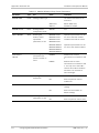
Connecting Data and Telecommunications Cables
Data and telecommunication interfaces are classified according to their safety status.
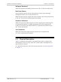
The following table lists the status of several standard interfaces. If the status of a given port
differs from the standard one, a notice will be given in the manual.
Ports
Safety Status
V.11, V.28, V.35, V.36, RS-530, X.21,
10 BaseT, 100 BaseT, Unbalanced E1,
E2, E3, STM, DS-2, DS-3, S-Interface
ISDN, Analog voice E&M
SELV
xDSL (without feeding voltage),
Balanced E1, T1, Sub E1/T1
TNV-1 Telecommunication Network Voltage-1:
FXS (Foreign Exchange Subscriber)
TNV-2 Telecommunication Network Voltage-2:
Ports whose normal operating voltage exceeds the
limits of SELV (usually up to 120 VDC or telephone
ringing voltages), on which overvoltages from
telecommunication networks are not possible. These
ports are not permitted to be directly connected to
external telephone and data lines.
FXO (Foreign Exchange Office), xDSL
(with feeding voltage), U-Interface
ISDN
TNV-3 Telecommunication Network Voltage-3:
Ports whose normal operating voltage exceeds the
limits of SELV (usually up to 120 VDC or telephone
ringing voltages), on which overvoltages from
telecommunication networks are possible.
Safety Extra Low Voltage:
Ports which do not present a safety hazard. Usually
up to 30 VAC or 60 VDC.
Ports whose normal operating voltage is within the
limits of SELV, on which overvoltages from
telecommunications networks are possible.
Always connect a given port to a port of the same safety status. If in doubt, seek the assistance
of a qualified safety engineer.
Always make sure that the equipment is grounded before connecting telecommunication cables.
Do not disconnect the ground connection before disconnecting all telecommunications cables.
Some SELV and non-SELV circuits use the same connectors. Use caution when connecting cables.
Extra caution should be exercised during thunderstorms.
When using shielded or coaxial cables, verify that there is a good ground connection at both
ends. The earthing and bonding of the ground connections should comply with the local codes.
The telecommunication wiring in the building may be damaged or present a fire hazard in case of
contact between exposed external wires and the AC power lines. In order to reduce the risk,
there are restrictions on the diameter of wires in the telecom cables, between the equipment
and the mating connectors.
Caution
To reduce the risk of fire, use only No. 26 AWG or larger telecommunication line
cords.
Attention
Pour réduire les risques s’incendie, utiliser seulement des conducteurs de
télécommunications 26 AWG ou de section supérieure.
Some ports are suitable for connection to intra-building or non-exposed wiring or cabling only. In
such cases, a notice will be given in the installation instructions.
Do not attempt to tamper with any carrier-provided equipment or connection hardware.
Electromagnetic Compatibility (EMC)
The equipment is designed and approved to comply with the electromagnetic regulations of
major regulatory bodies. The following instructions may enhance the performance of the
equipment and will provide better protection against excessive emission and better immunity
against disturbances.
A good earth connection is essential. When installing the equipment in a rack, make sure to
remove all traces of paint from the mounting points. Use suitable lock-washers and torque. If an
external grounding lug is provided, connect it to the earth bus using braided wire as short as
possible.
The equipment is designed to comply with EMC requirements when connecting it with unshielded
twisted pair (UTP) cables. However, the use of shielded wires is always recommended, especially
for high-rate data. In some cases, when unshielded wires are used, ferrite cores should be
installed on certain cables. In such cases, special instructions are provided in the manual.
Disconnect all wires which are not in permanent use, such as cables used for one-time
configuration.
The compliance of the equipment with the regulations for conducted emission on the data lines
is dependent on the cable quality. The emission is tested for UTP with 80 dB longitudinal
conversion loss (LCL).
Unless otherwise specified or described in the manual, TNV-1 and TNV-3 ports provide secondary
protection against surges on the data lines. Primary protectors should be provided in the building
installation.
The equipment is designed to provide adequate protection against electro-static discharge (ESD).
However, it is good working practice to use caution when connecting cables terminated with
plastic connectors (without a grounded metal hood, such as flat cables) to sensitive data lines.
Before connecting such cables, discharge yourself by touching earth ground or wear an ESD
preventive wrist strap.
FCC-15 User Information
This equipment has been tested and found to comply with the limits of the Class A digital device,
pursuant to Part 15 of the FCC rules. These limits are designed to provide reasonable protection
against harmful interference when the equipment is operated in a commercial environment. This
equipment generates, uses and can radiate radio frequency energy and, if not installed and used
in accordance with the Installation and Operation manual, may cause harmful interference to the
radio communications. Operation of this equipment in a residential area is likely to cause harmful
interference in which case the user will be required to correct the interference at his own
expense.
Canadian Emission Requirements
This Class A digital apparatus meets all the requirements of the Canadian Interference-Causing
Equipment Regulation.
Cet appareil numérique de la classe A respecte toutes les exigences du Règlement sur le matériel
brouilleur du Canada.
Warning per EN 55022 (CISPR-22)
Warning
Avertissement
Achtung
This is a class A product. In a domestic environment, this product may cause radio
interference, in which case the user will be required to take adequate measures.
Cet appareil est un appareil de Classe A. Dans un environnement résidentiel, cet
appareil peut provoquer des brouillages radioélectriques. Dans ces cas, il peut être
demandé à l’utilisateur de prendre les mesures appropriées.
Das vorliegende Gerät fällt unter die Funkstörgrenzwertklasse A. In Wohngebieten
können beim Betrieb dieses Gerätes Rundfunkströrungen auftreten, für deren
Behebung der Benutzer verantwortlich ist.
Declaration of Conformity
Manufacturer's Name:
RAD Data Communications Ltd.
Manufacturer's Address:
24 Raoul Wallenberg St., Tel Aviv 69719, Israel
declares that the product:
Product Name:
ASMi-52CQ
conforms to the following standard(s) or other normative document(s):
EMC:
Safety:
EN 55022:1998
Information technology equipment – Radio
disturbance characteristics – Limits and methods of
measurement.
EN 50024: 1998
A1:2001, A2:2003
Information technology equipment – Immunity
characteristics – Limits and methods of
measurement.
EN 60950: 2001
Information technology equipment – Safety – Part 1:
General requirements.
Supplementary Information:
The product herewith complies with the requirements of the EMC Directive 89/336/EEC, the Low
Voltage Directive 73/23/EEC and the R&TTE Directive 1999/5/EC for wired equipment. The
product was tested in a typical configuration.
Tel Aviv, 4 September 2005
Haim Karshen
VP Quality
European Contact: RAD Data
Ottobrunn-Riemerling, Germany
Communications
GmbH,
Otto-Hahn-Str.
28-30,
85521
Quick Start Guide
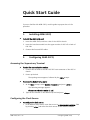
If you are familiar with ASMi-52CQ, use this guide to prepare the unit for
operation.
1.
³
Installing ASMi-52CQ
To install the ASMi-52CQ card:
1. Insert the ASMi-52CQ card into a slot of the LRS-24 chassis.
2. Insert the interface module into the upper section of LRS-24F or back of
LRS-24B.
3. Connect the line and DCE cables.
2.
Configuring ASMi-52CQ
Accessing the Supervisory Terminal
³
To start the communication session:
1. Connect the terminal to the CM-2 RS-232 front connector of the LRS-24
chassis.
2. Power up the hub.
The opening screen appears, followed by the CM2> prompt.
³
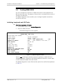
To access the Modem Setup menu:
1. At the CM2> prompt, select Modem Parameters and press <Enter>.
The following message appears:
Please enter the slot number (1-12)
2. Type the slot number of the ASMi-52CQ card and press <Enter>.
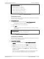
Configuring the Clock Source
³
To configure the clock source:
•
ASMi-52CQ Ver. 2.12
In the Modem Setup menu, move the cursor to CLOCK SOURCE LOC/REM field
by pressing <Tab> and select the clock source for the selected modem.
Configuring ASMi-52CQ
1
Quick Start Guide
Installation and Operation Manual
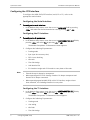
Configuring the DTE Interface
To configure the ASMi-52CQ DTE interface (serial, E1 or T1), refer to the
appropriate section below.
Configuring the Serial Interface
³
To configure the serial interface:
•
In the Modem Setup menu, move the cursor to DATA RATE field by pressing
<Tab> and select the desired transmission rate by pressing <F> or <B>.
Configuring the E1 Interface
³
To configure the E1 parameters:
1. In the Modem Setup menu, move the cursor to NEXT PARMETERS (E1) field by
pressing <Tab> and select YES by pressing <F> or <B>.
The Modem Setup Menu: E1 Parameters screen appears.
2. Configure the following E1 parameters:
Note
Framing mode
Sync (sync loss recovery time)
CRC-4 error checking
Idle code
Time Slot Assign
Unit Identical Set
E1 timeslots: Assign each E1 timeslot to carry data or idle code.
•
Timeslot 0 may be looped or transparent.
•
When operating with G732S framing, timeslot 0 is always transparent and
timeslot 16 is always connected.
•
When operating opposite ASMi-52CQ with V.35 interface, assign at least
three timeslots, not including timeslot 0 to carry data.
Configuring the T1 Interface
1. In the Modem Setup menu, move the cursor to NEXT PARMETERS (T1) field by
pressing <Tab> and select YES by pressing <F> or <B>.
The Modem Setup menu: T1 Parameters screen appears.
2. Configure the following T1 parameters:
2
Framing mode
Line coding
Idle Code
Time Slot Assign
Configuring ASMi-52CQ
ASMi-52CQ Ver. 2.12
Installation and Operation Manual
Unit Identical Set
Receive gain
Interface
Transmit signal mask (DSU mode)
Transmit signal mask (CSU mode)
Fbit configuration.
Quick Start Guide
Configuring the Line Parameters
³
To configure the line parameters:
1. If you have configured E1/T1 parameters, press <ESC> to return to the main
menu, and then repeat the steps above to access the Modem Setup menu.
2. In the Modem Setup menu, move the cursor to NEXT PARMETERS (LINE) field
by pressing <Tab> and select YES by pressing <F> or <B>.
The Modem Setup Menu: Line Parameters screen appears.
3. Configure the following line parameters:
ASMi-52CQ Ver. 2.12
Power backoff
Snext margin, if line probing is set to adaptive
Current margin, if line probing is set to adaptive
Power spectral density (line probing set to fixed only)
Line probing
Transmission mode
Loop attenuation threshold
SNR margin threshold.
Configuring ASMi-52CQ
3
Quick Start Guide
4
Configuring ASMi-52CQ
Installation and Operation Manual
ASMi-52CQ Ver. 2.12
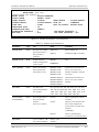
Contents
Chapter 1. Introduction
1.1
1.2
1.3
1.4
Overview.................................................................................................................... 1-1
Product Options...................................................................................................... 1-1
Application ............................................................................................................. 1-1
Features ................................................................................................................. 1-2
Line Interface ..................................................................................................... 1-2
DTE Interface ..................................................................................................... 1-3
Timing................................................................................................................ 1-4
Remote Management ......................................................................................... 1-4
Diagnostics ........................................................................................................ 1-4
Software Download............................................................................................ 1-5
Real-time Alarms ................................................................................................ 1-5
Statistics Collection ............................................................................................ 1-5
Line Protection................................................................................................... 1-5
Physical Description ................................................................................................... 1-5
Functional Description................................................................................................ 1-7
Technical Specifications.............................................................................................. 1-8
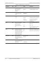
Chapter 2. Installation and Operation
2.1
2.2
2.3
2.4
2.5
Introduction ............................................................................................................... 2-1
Site Requirements and Prerequisites .......................................................................... 2-1
Package Contents ...................................................................................................... 2-2
Installing ASMi-52CQ .................................................................................................. 2-2
Installing the Modem Card....................................................................................... 2-3
Installing the Interface Modules .............................................................................. 2-3
Inspecting the Interface Module ......................................................................... 2-3
Installing the Interface Module into the Chassis .................................................. 2-3
Connecting the Interfaces .......................................................................................... 2-3
Connecting the LRSI-F-18 Interface ......................................................................... 2-4
Connecting the LRSI-F-19 Interface ......................................................................... 2-5
Connecting the LRSI-F-20 Interface ......................................................................... 2-6
Connecting the LRSI-F-21 Interface ......................................................................... 2-7
Connecting the LRSI-F-27 Interface ......................................................................... 2-8
Connecting the LRSI-F-28 Interface ......................................................................... 2-9
Connecting the LRSI-F-29 Interface ....................................................................... 2-10
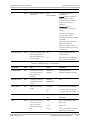
Chapter 3. Operation
3.1
3.2
3.3
3.4
3.5
Turning ASMi-52CQ On ............................................................................................... 3-1
Controls and Indicators .............................................................................................. 3-1
Front Panel LEDs ..................................................................................................... 3-1
Normal Operation ................................................................................................... 3-3
Initiating an ASCII Terminal Session............................................................................. 3-3
Navigating the Menus ................................................................................................ 3-4
Turning ASMi-52CQ Off .............................................................................................. 3-5
ASMi-52CQ Ver. 2.12
i
Table of Contents
Installation and Operation Manual
Chapter 4. Configuration
4.1
4.2
4.3
Introduction ............................................................................................................... 4-1
Configuring the Modem .............................................................................................. 4-2
Configuring the Clock Source................................................................................... 4-2
Configuring the DTE Interface ................................................................................. 4-3
Configuring the Serial Interface .......................................................................... 4-3
Configuring the E1 Interface ............................................................................... 4-3
Configuring the T1 Interface ............................................................................... 4-4
Configuring the Line Parameters ............................................................................. 4-4
Memory Downloading ................................................................................................ 4-5
CPU and Memory Elements...................................................................................... 4-5
Flash Memory..................................................................................................... 4-5
Download Procedure ............................................................................................... 4-6
Defining Type of Download ................................................................................ 4-6
Downloading via LAN.......................................................................................... 4-7
Downloading via XMODEM .................................................................................. 4-7
Downloading via CM-2 Flash Memory .................................................................. 4-8
Changing Modem Software Version ......................................................................... 4-8
Viewing Existing Versions of Modem Software ......................................................... 4-9
Downloading a New Software Version to All the ASMi-52CQ Modems ...................... 4-9
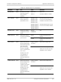
Chapter 5. Troubleshooting and Diagnostics
5.1
5.2
5.3
5.4
5.5
5.6
5.7
Introduction ............................................................................................................... 5-1
Monitoring Performance ............................................................................................. 5-2
Displaying SHDSL Performance ................................................................................ 5-2
Displaying E1/T1 Performance ................................................................................. 5-2
Handling Alarms ......................................................................................................... 5-4
Viewing Alarm Messages from an ASCII Terminal ...................................................... 5-4
Troubleshooting ......................................................................................................... 5-8
Using LEDs.............................................................................................................. 5-8
Using the Alarm Buffer ............................................................................................ 5-8
Testing ASMi-52CQ .................................................................................................... 5-9
Initiating Loopback and LED Tests ........................................................................... 5-9
Setting Loopback Tests ......................................................................................... 5-11
Running the Local Analog Loopback.................................................................. 5-11
Running the Remote Digital Loopback .............................................................. 5-11
Running the Bit Error Rate Test (BERT) .................................................................. 5-12
Frequently Asked Questions ..................................................................................... 5-13
Technical Support .................................................................................................... 5-14
Appendix A. Pinouts
Appendix B. Parameter List
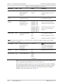
Appendix C. LRSI-F-27 Module
ii
ASMi-52CQ Ver. 2.12
Chapter 1
Introduction
1.1
Overview
ASMi-52CQ is a card containing four independent 2-wire Synchronous High Bit
Rate Digital Subscriber Line (SHDSL) modems operating in full-duplex over 2-wire
lines. It offers a cost effective solution delivering digital data to customer
premises over existing copper cables. ASMi-52CQ handles multiples data rates in
the range of 64–2304 kbps. The modem card includes four modems, supporting
RS-530, V.35, X.21 and E1/T1 DTE interfaces. ASMi-52CQ uses TC-PAM coding and
complies with the ITU-T G.991.2 requirements.
ASMi-52CQ is housed within RAD's compact 12-slot LRS-24 Access Rack, enabling
up to 48 modems in one rack and drastically reducing port price. LRS-24 is
managed by the RADview SNMP management tool, Telnet or an ASCII terminal.
A card can be removed and re-inserted without powering down the system and
without affecting operation of other modules in the system.
Product Options
ASMi-52CQ is available in the following versions.
•
ASMi-52CQF (ETSI)
•
ASMi-52CQB (ANSI).
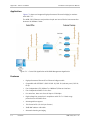
Application
ASMi-52CQ can establish a communication link with an ASMi-52 standalone
modem whose data rate is between 64 kbps and 2304 kbps (see Table 1-1). A
central site application for ASMi-52CQ with SNMP management is shown in
Figure 1-1.
Note
The ASMi-52CQ operates opposite standalone ASMi-52 or ASMi-52L devices only.
ASMi-52CQ Ver. 2.12
Overview
1-1
Chapter 1 Introduction
Installation and Operation Manual
Figure 1-1. Central Site Application with SNMP Management Application
Features
Line Interface
ASMi-52CQ operates over 2-wire lines. ASMi-52CQ extends the range of data
transmission over 2-wire lines up to 7.0 km (4.3 miles), by employing SHDSL
TC-PAM technology. ASMi-52CQ operation complies with the requirements of the
ITU-T G.991.2 standard.
Table 1-1 lists typical ASMi-52CQ ranges over 26 AWG line.
Table 1-1. Typical ASMi-52CQ Ranges over 26 AWG
Data Rate
1-2
Overview
Range
[kbps]
[km]
[miles]
64
7.0
4.3
128
7.0
4.3
256
7.0
4.3
384
6.0
3.7
512
5.5
3.4
1024
4.2
2.6
2048
3.5
2.2
2304
3.4
2.1
ASMi-52CQ Ver. 2.12
Installation and Operation Manual
Chapter 1 Introduction
DTE Interface
ASMi-52CQ supports a wide range of digital interfaces: RS-530, V.35, X.21, G.704
E1/T1, and UTP (10BaseT or 100BaseT) Ethernet interface. The required interface
is provided using the appropriate interface module.
Table 1-2 lists the ASMi-52CQ digital interface versions with their appropriate
interface modules and DCE connectors.
Note
LRSI-27 (ETH) module operates with ASMi-52CQ-Ethernet card only.
Table 1-2. ASMi-52CQ Interface Modules
Interface
Module
DTE
Interface
LRSI-F-18
LRSI-B-18
Connector
DTE
Line
RS-530
SCSI 68-pin cable adapter for four 25-pin
D-type female connectors
RJ-11
X.21
SCSI 68-pin cable adapter for four 15-pin
D-type female connectors
RJ-11
V.35
SCSI 68-pin cable adapter for four 34-pin
female connectors
RJ-11
RS-530
SCSI 68-pin cable adapter for four 25-pin
D-type female connectors
Terminal block
X.21
SCSI 68-pin cable adapter for four 15-pin
D-type female connectors
Terminal block
V.35
SCSI 68-pin cable adapter for four 34-pin
female connectors
Terminal block
LRSI-F-20
LRSI-B-20
G.704 E1/T1
Four RJ-11 connectors, balanced
Terminal block
LRSI-F-21
LRSI-B-21
G.704 E1
25-pin D-type female, unbalanced
Terminal block
LRSI-F-27
LRSI-B-27
ETH
Four RJ-45 connectors
Terminal block
LRSI-F-28
LRSI-B-28
Balanced
G.704 E1/T1
Four RJ-11 connectors
Two RJ-45
connectors
LRSI-F-29
LRSI-B-29
Unbalanced
G.704 E1
25-pin D-type female
Two RJ-45
connectors
LRSI-F-19
LRSI-B-19
ASMi-52CQ Ver. 2.12
Overview
1-3
Chapter 1 Introduction
Installation and Operation Manual
Timing
ASMi-52CQ supports three clock modes:
•
•
•
•
Internal, derived from its internal oscillator
External, supplied by the attached DTE
System, supplied by the LRS-24 station clock input
Receive, derived from the SHDSL line
Table 1-3 details the ASMi-52CQ data rates with all possible combinations of DTE
interface types and clock modes. Each port can have its own separate clocking.
Note
If the DTE interface is E1 or T1 and receive clocking is chosen for one port, all
ports must use receive clocking.
Table 1-3. ASMi-52CQ Data Rates
DTE Interface
Clock Mode
Data Rate
V.35, RS-530, X.21, ETH
Internal
n × 64 kbps (n = 1, 2, …, 32, 36)
V.35, RS-530, X.21
External
n × 64 kbps (n = 1, 2, …, 36)
V.35, RS-530, X.21, ETH
Station
n × 64 kbps (n = 1, 2, …, 32)
E1
Internal, external, station, receive
n × 64 kbps (n = 1, 2, …, 32)
T1
Internal, external, station, receive
n × 64 kbps (n = 1, 2, …, 24)
Remote Management
ASMi-52CQ allows full management of the local and remote modems using SNMP
management, Telnet or an ASCII terminal via the CM-2 card of the LRS-24 modem
rack. Management of the remote unit is achieved via an inband channel that
allows simultaneous remote configuration for both modems, real-time alerts on
failures, diagnostic tests, and statistical information on system performance. The
configuration parameters are stored in card flash memory.
The modem uses an Embedded Operation Channel (EOC) for controlling and
monitoring the remote unit in accordance with the SHDSL (G.991.2) standard.
The management channel operates without interfering with data transmission.
The operator can perform diagnostic tests from the remote ASMi-52 modem.
Diagnostics
ASMi-52CQ has comprehensive diagnostics capabilities that are activated from
either the ASCII terminal or from an SNMP management tool. They include the
following test options:
•
V.54 local analog and remote digital loopbacks
•
V.54 BER test
•
SHDSL statistics collection.
All tests can be activated from the local unit or from the remote unit. SHDSL
statistics can be activated from the RADview SNMP management tool.
1-4
Overview
ASMi-52CQ Ver. 2.12
Installation and Operation Manual
Chapter 1 Introduction
Software Download
ASMi-52CQ supports downloading software from CM-2 to the local modem card.
Real-time Alarms
Real-time alarms provide real time information on system status indicating
management failure, loss of synchronization, etc.
ASMi-52CQ also features a log file that stores all alarms and events that occurred
in the unit. These alarms can be displayed and cleared.
Statistics Collection
ASMi-52CQ stores the SHDSL statistics for the line performance monitoring. This
is accessed from RADview, an SNMP management tool. When equipped with
G.704 E1/T1 interface, the modem collects E1/T1 performance statistics as per
ITU-T G.706 requirements.
Line Protection
ASMi-52CQ incorporates high-voltage line protection in compliance with
ITU-T K.21 surge protection standard.
1.2
Physical Description
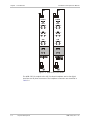
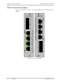
Figure 1-2 shows the front panels of the ASMi-52CQ module. It includes LEDs
that display the status of power, data flow, control signals, and diagnostics for
each of the four modems.
For a detailed description of the LED functions and states, see Front Panel LEDs
in Chapter 3.
ASMi-52CQ Ver. 2.12
Physical Description
1-5
Chapter 1 Introduction
Installation and Operation Manual
POWER
POWER
DATA
DATA
1
2
1
2
3
4
3
4
1
2
1
2
3
4
3
4
1
2
1
2
3
4
3
4
TST
TST
ALM
ALM
SYNC
SYNC
1
2
1
2
3
4
3
4
Figure 1-2. ASMi-52CQ Front Panels
The ASMi-52CQ is coupled to the LRS-24 chassis backplane and to the digital
interface card by three connectors. The backplane connectors are described in
Table 1-4.
1-6
Physical Description
ASMi-52CQ Ver. 2.12
Installation and Operation Manual
Chapter 1 Introduction
Table 1-4. ASMi-52CQ Connectors
Connector
No. of Pins
Function
Use
J5
96
Data
Carrying data and signaling to/from the
Interface module in the LRS-24 chassis.
J6
48
Control
Carrying management information between
the ASMi-52CQ module and the control
module (CM-2) and supplying -5V from the
chassis power supply module.
J11
8
Power
Supplying +5V from the chassis power
supply module.
1.3
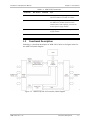
Functional Description
Following is a functional description of ASMi-52CQ. Refer to the figure below for
the ASMi-52CQ block diagram.
Figure 1-3. ASMi-52CQ with V.35 Interface, Block Diagram
ASMi-52CQ Ver. 2.12
Functional Description
1-7
Chapter 1 Introduction
Installation and Operation Manual
The ASMi-52CQ modem card consists of the following major modules:
•
SHDSL Interface Module – This module translates the received and
transmitted data from the four lines to the four DTE interfaces.
•
Modem Glue Logic Module – This module processes the data from/to the
SHDSL interface module.
•
Administration Data Transfer Module – This module manages the data
transfer between the modems on both sides of the line.
•
Modem Controller – This module, based on a MC68302 microprocessor,
controls the ASMi-52CQ operation.
•
LEDs Module – This module provides modem status information via LED
indicators on the front panel.
•
Digital Interface – This module prepares the digital data coming from the DTE
into a data stream for the modem glue logic. In addition it translates the data
from the modem glue logic into digital data to be sent to the DTE.
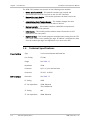
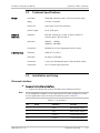
1.4
Line Interface
DTE Interface
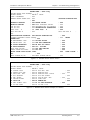
Technical Specifications
Type
2-wire unconditioned dedicated line
Line Coding
TC-PAM
Range
See Table 1-1
Impedance
135Ω
Connector
RJ-11 or 2-pin terminal block
Protection
ITU K.21, UL1950
Data Rate
See Table 1-3
E1 Coding
HDB3
E1 Line Impedance
120Ω, Balanced
75Ω, Unbalanced
1-8
T1 Coding
AMI
T1 Line Impedance
100Ω, Balanced
Technical Specifications
ASMi-52CQ Ver. 2.12
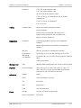
Installation and Operation Manual
Connector
Chapter 1 Introduction
V.35: SCSI-68 and adapter cable
X.21: SCSI-68 and adapter cable
RS-530: SCSI-68 and adapter cables
G.704 E1: four RJ-11s (Balanced) or DB-25 female
(Unbalanced)
G.704 T1: four RJ-11s (Balanced)
ETH: four RJ-45s
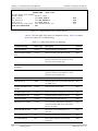
Timing
Transmit Clock
Derived from three alternative sources:
Internal oscillator
External, from the attached DTE (except ETH)
System, distributed by the LRS-24 modem rack
Receive, from the SHDSL line
Diagnostics
Loopbacks
Local analog loopback, activated via management
software
Remote digital loopback, activated via management
software
BER Test
BER test, activated via management software
Performance
Monitoring
(via RADview)
E1 with CRC-4 or T1 with ESF framing: per ITU G.706
E1 without CRC-4 or T1 with SF framing: bipolar violations
(BPV)
SHDSL performance
Management
Type
RADview SNMP management tool, Telnet or ASCII terminal
Physical
Interface Module
LRSI-F-18, LRSI-F-19, LRSI-F-20, LRSI-F-21, LRSI-F-27,
LRSI-F-28, LRSI-F-29 one for each ASMi-52CQ module
connected to four DTE and four line ports
Indicators
POWER
Power
DATA
Data transmitted or received
TST
Test mode
ALM
Alarm occurs
SYNC
Line synchronization
Voltage
+5V and -5V, both fuse-protected
Power Consumption
10.5W max.
Power
ASMi-52CQ Ver. 2.12
Technical Specifications
1-9
Chapter 1 Introduction
Environment
1-10
Installation and Operation Manual
Temperature
0°–45°C (32°–113°F)
Humidity
Up to 90%, non–condensing
Technical Specifications
ASMi-52CQ Ver. 2.12
Chapter 2
Installation and Operation
2.1
Introduction
This chapter provides installation and operation instructions for the ASMi-52CQ
card and the applicable Interface modules. The information presented in this
chapter supplements the general instructions for installation and operation of the
LRS-24F or LRS-24B chassis.
After installing the ASMi-52CQ modem and interface module and powering up the
chassis, the front panel LEDs should assume the states as shown in Chapter 3. In
case of a problem, refer to Chapter 6. For system configuration, refer to
Chapter 4.
The operator or the user should not perform internal settings, adjustment,
maintenance, and repairs; such operations should only be performed by a skilled
technician aware of the hazards involved.
Warning
Always observe standard safety precautions during the installation, operation,
and maintenance of this product.
Caution The ASMi-52CQ module contains components sensitive to electrostatic discharge
(ESD). To prevent ESD damage, always hold modules by the sides and do not
touch the module components or connectors.
Note
Before installing the product, review Handling Energized Products at the
beginning of the manual.
2.2
Site Requirements and Prerequisites
ASMi-52CQ cards are installed in a LRS-24 chassis. See the LRS-24 Installation
and Operation Manual for instructions on operating the LRS-24.
The ambient operating temperature of ASMi-52CQ should be 32° to 113°F
(0° to 45°C), at a relative humidity of up to 90%, non-condensing.
ASMi-51CQ modem cards installed in the LRS-24 hub require cooling. This is
provided by a fan tray installed under the LRS-24.
ASMi-52CQ Ver. 2.12
2BSite Requirements and Prerequisites
2-1
Chapter 2 Installation and Operation
2.3
Installation and Operation Manual
Package Contents
The ASMi-52CQ package includes the following items:
•
ASMi-52CQ modem card
•
Matching interface module
•
Technical documentation CD
•
Adapter cable for connecting an interface module to the appropriate DTE:
RS-530 – CBL-CQ-RS530/F (if ordered)
One SCSI-68 to four female RS-530 (DB-25) connectors
V.35 – CBL-CQ-V35/F (if ordered)
One SCSI-68 to four female V.35 (34-pin) connectors
X.21 – CBL-CQ-X21/F (if ordered)
One SCSI-68 to four female X.21 (DB-15) connectors
Unbalanced G.704 E1 – CBL-LRSI21/DB25/UB/M (if ordered)
One DB-25 to eight male BNC coax connectors
Unbalanced G.704 E1 – CBL-LRSI21/DB25/UB/F (if ordered)
One DB-25 to eight female BNC coax connectors.
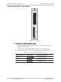
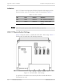
2.4
Installing ASMi-52CQ
Figure 2-1 illustrates layout of the ASMi-52CQ module.
0
POWER
DATA
J5
TST
ALM
SYNC
J6
J11
Figure 2-1. ASMi-52CQ Layout
2-2
Installing ASMi-52CQ
ASMi-52CQ Ver. 2.12
Installation and Operation Manual
Chapter 2 Installation and Operation
Installing the Modem Card
³
To install the ASMi-52CQ card into the LRS-24 chassis:
1. Refer to the system installation plan and insert the ASMi-52CQ module in the
assigned I/O slot of the LRS-24 enclosure.
2. Fasten the two front panel screws to secure the module to the LRS-24 frame
for proper grounding.
Installing the Interface Modules
Inspecting the Interface Module
Check that the supplied interface modules meet the physical and electrical
interface requirements of the installation site, according to Table 1-2.
Note
LRSI-F-xx interface modules are placed in the top section of the LRS-24F chassis;
LRSI-B-xx interface modules are placed in the back section of the LRS-24B
chassis.
Installing the Interface Module into the Chassis
³
To install the interface module into the LRS-24 chassis:
1. Insert the interface module into the upper section above the ASMi-52CQ
module of the LRS-24F chassis, or back section of the LRS-24B chassis.
2. Fasten two front panel screws to secure the module to the LRS-24 frame for
proper grounding.
2.5
Connecting the Interfaces
The ASMi-52CQ modem is connected to the line and DTE via the interface
module. Identify the necessary cables for the interface module you have installed
and prepare the line and DCE cables.
For details about preparing the line cables, see Appendix B.
Note
The connection instructions for the B-type interfaces are identical to those
shown for the following F-type interfaces.
ASMi-52CQ Ver. 2.12
Connecting the Interfaces
2-3
Chapter 2 Installation and Operation
Installation and Operation Manual
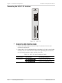
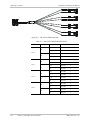
Connecting the LRSI-F-18 Interface
LRSI-F-18
1
2
3
L
I
N
E
4
DCE
Figure 2-2. LRSI-F-18
³
To connect the LRSI-F-18 interface module:
1. Connect the SHDSL cables terminated in RJ-11 connectors into the card
connectors marked LINE.
2. Connect a 68-pin SCSI adapter cable into the connector marked DCE.
Depending on the interface, use the following cables available from RAD:
Table 2-1. LRSI-F-18 Interface Adapter Cables
2-4
DCE Interface Type
Cable Number
Terminating Connectors
RS-530
CBL-CQ-RS530/F
4 female DB-25 RS-530
V.35
CBL-CQ-V35/F
4 female 34-pin V.35
X.21
CBL-CQ-X21/F
4 female DB-15 X.21
Connecting the Interfaces
ASMi-52CQ Ver. 2.12
Installation and Operation Manual
Chapter 2 Installation and Operation
Connecting the LRSI-F-19 Interface
LRSI-F-19
1
L
I
N
E
2
3
4
DCE
Figure 2-3. LRSI-F-19
³
To connect the LRSI-F-19 interface module:
1. Connect the SHDSL cables terminated in terminal blocks into the connectors
marked LINE.
2. Connect a 68-pin SCSI adapter cable into the connector marked DCE.
Depending on the interface, use the following cables available from RAD:
Table 2-2. LRSI-F-19 Interface Adapter Cables
ASMi-52CQ Ver. 2.12
DCE Interface Type
Cable Number
Terminating Connectors
RS-530
CBL-CQ-RS530/F
4 female DB-25 RS-530
V.35
CBL-CQ-V35/F
4 female 34-pin V.35
X.21
CBL-CQ-X21/F
4 female DB-15 X.21
Connecting the Interfaces
2-5
Chapter 2 Installation and Operation
Installation and Operation Manual
Connecting the LRSI-F-20 Interface
LRSI-F-20
1
2
3
L
I
N
E
4
1
2
3
D
C
E
4
Figure 2-4. LRSI-F-20
³
To connect the LRSI-F-20 interface module:
1. Connect the SHDSL cables terminated in terminal blocks into the card
connectors marked LINE.
2. Connect the G.704 E1/T1 balanced lines terminating in RJ-11 connectors into
the card connectors marked DCE.
2-6
Connecting the Interfaces
ASMi-52CQ Ver. 2.12
Installation and Operation Manual
Chapter 2 Installation and Operation
Connecting the LRSI-F-21 Interface
LRSI-F-21
1
2
3
L
I
N
E
4
D
C
E
Figure 2-5. LRSI-F-21
³
To connect the LRSI-F-21 interface module:
1. Connect the SHDSL cables terminated in terminal blocks into the card
connectors marked LINE.
2. Connect the G.704 E1 unbalanced lines terminating in a 25-pin D-type female
connector into the card connector marked DCE. Depending on the interface,
use the following adapter cables available from RAD:
Table 2-3. LRSI-F-21 Interface Adapter Cables
ASMi-52CQ Ver. 2.12
Interface Type
Cable Number
Terminating Connectors
Unbalanced E1
CBL-LRSI21/DB25/UB/M
1 DB-25 to 8 male BNC coax
CBL-LRSI21/DB25/UB/F
1 DB-25 to 8 female BNC coax
Connecting the Interfaces
2-7
Chapter 2 Installation and Operation
Installation and Operation Manual
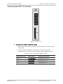
Connecting the LRSI-F-27 Interface
Figure 2-6. LRSI-F-27
³
To connect the LRSI-F-27 interface module:
1. Connect the SHDSL cables terminated in terminal blocks into the card
connectors marked LINE.
2. Connect the Ethernet lines terminating in RJ-45 connectors into the card
connectors marked Ethernet.
For more details on the Ethernet interface see Appendix C.
2-8
Connecting the Interfaces
ASMi-52CQ Ver. 2.12
Installation and Operation Manual
Chapter 2 Installation and Operation
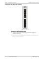
Connecting the LRSI-F-28 Interface
LRSI-F-28
1
L
I
N
E
2
1
2
3
D
C
E
4
Figure 2-7. LRSI-F-28
³
To connect the LRSI-F-28 interface module:
1. Connect the SHDSL cables terminated in RJ-45 connectors into the card
connectors marked LINE.
2. Connect the G.704 E1/T1 balanced lines terminating in RJ-11 connectors into
the card connectors marked DCE.
ASMi-52CQ Ver. 2.12
Connecting the Interfaces
2-9
Chapter 2 Installation and Operation
Installation and Operation Manual
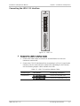
Connecting the LRSI-F-29 Interface
LRSI-F-29
1
L
I
N
E
2
D
C
E
Figure 2-8. LRSI-F-29
³
To connect the LRSI-F-29 interface module:
1. Connect the SHDSL cables terminated in RJ-45 connectors into the card
connectors marked LINE.
2. Connect the G.704 E1 unbalanced lines terminating in a 25-pin D-type female
connector into the card connector marked DCE. Depending on the interface,
use the following adapter cables available from RAD:
Table 2-4. LRSI-F-29 Interface Adapter Cables
2-10
Interface Type
Cable Number
Terminating Connectors
Unbalanced E1
CBL-LRSI21/DB25/UB/M
1 DB-25 to 8 male BNC coax
CBL-LRSI21/DB25/UB/F
1 DB-25 to 8 female BNC coax
Connecting the Interfaces
ASMi-52CQ Ver. 2.12
Chapter 3
Operation
This chapter:
•
Provides a description of the front panel controls and indicators
•
Explains power-on and power-off procedures
•
Provides instructions for using a terminal connected to the ASMi-52CQ
control port
•
Describes how to navigate menus.
3.1
³
Turning ASMi-52CQ On
To power on ASMi-52CQ:
•
Turn on the LRS-24 modem rack.
After power-up, all LEDs turn on for 3 seconds while the CPU initiates the
ASMi-52CQ module.
After synchronization between the two modems has been achieved, the
ASMi-52CQ module assumes the normal state according to the LED
indications in Table 3-2.
For other LED indications, see Figure 3-1.
For troubleshooting, see Chapter 5.
3.2
Controls and Indicators
Front Panel LEDs
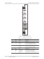
Figure 3-1 shows the front panel of the ASMi-52CQ module. Table 3-1 lists the
functions of the ASMi-52CQ front panel indicators.
ASMi-52CQ Ver. 2.12
Controls and Indicators
3-1
Chapter 3 Operation
Installation and Operation Manual
POWER
DATA
1
2
3
4
TST
1
2
3
4
ALM
1
2
3
4
SYNC
1
2
3
4
Figure 3-1. ASMi-52CQ Front Panel
Table 3-1. ASMi-52CQ Front Panel LEDs
ID
Color
Status
Indication
POWER
Green
ON
Power is On
DATA
Yellow
Blinking
Data is transmitted or received
OFF
No data is transmitted or received
ON
Test mode is active in local or remote unit
Blinking
Software download is in progress
TST
3-2
Red
ALM
Red
ON
Alarm active
SYNC
Green/
Red
ON (green)
Both modems are synchronized
Blinking (red)
Synchronization is taking place
ON (red)
Synchronization was lost between modems
Controls and Indicators
ASMi-52CQ Ver. 2.12
Installation and Operation Manual
Chapter 3 Operation
Normal Operation
After power-up the LEDs should assume the states as shown in Table 3-2.
Table 3-2. Normal State of LEDs
3.3
³
ID
Color
State
POWER
Green
ON
DATA
Yellow
Blinking
TST
Red
OFF
ALM
Red
OFF
SYNC
Green/Red
Green
Initiating an ASCII Terminal Session
To enable an ASCII terminal session:
1. Connect the terminal to the CM-2 RS-232 front connector of the LRS-24
chassis.
2. Power up the hub.
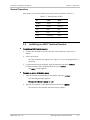
The LRS-24 Main menu appears (see Figure 3-2). You are prompted for a
password.
3. If a password has been assigned, type the password and press <Enter>.
If no password has been assigned (default), press <Enter>.
The CM2> prompt appears.
³
To select an option in the Main menu:
1. Type the number corresponding to the option and press <Enter>.
The following message appears:
Please enter the slot number (1-12)
2. Type the slot number of the ASMi-52CQ card and press <Enter>.
The screen for the selected command option appears.
ASMi-52CQ Ver. 2.12
Initiating an ASCII Terminal Session
3-3
Chapter 3 Operation
Installation and Operation Manual
L
L
L
L
LLLL
RRRRR
R
R
RRRRR
R R
R RR
SSSS
S
SS
---S
SSSS
222
2
2
2
2
22222
4
4
4
4
444444
4
4
RAD DATA COMMUNICATIONS LTD
Please Choose Command ID:
1.
System Configuration
2.
System Status
3.
System manager list
4.
System card type define
5.
System Alarms
6.
System Log-file
7.
System control port
8.
System Download
9.
System management access
10. System Dial out modem
11. System Reset
CM2 >
12.
13.
14.
15.
16.
17.
18.
19.
20.
21.
Modem/Hub Auto Configuration
Modem Operation
Modem Status
Modem Diagnostics
Modem Alarms
Modem Log-file
Modem Download
Modem Parameters
Modems SW Version
Help
Figure 3-2. LRS-24 Main Menu
3.4
Navigating the Menus
The menus are navigated using the keystrokes described in Table 3-3.
Table 3-3. Keys to Navigate Menus
Key
Function
<Tab>
Moving from field to field. Pressing <Tab> in the last field brings the
cursor back to the first field on the screen.
<F> or <U>
Viewing the next parameter value in the list
<B> or <D>
Viewing the previous parameter value in the list
<Enter>
Saving parameter values and exiting the screen
<Esc>
Exiting the screen without saving parameter values
The table below describes the menus and screens used to perform common
configuration functions.
3-4
Navigating the Menus
ASMi-52CQ Ver. 2.12
Installation and Operation Manual
Chapter 3 Operation
Table 3-4. Configuration Menus and Screens
LRS-24 Main Menu Item
Screen Name
Function
Modem Operation
Modem Advanced
Setup
Setting operational parameters. This
screen is needed to switch control or to
load configurable parameters from one
modem to the other
Modem Parameters
Modem Setup
Configuring parameters of both modems
Modem Status
Modem Status
Viewing types of both digital and line
interfaces and LED indications, also the
modem’s current software and hardware
version.
Modem Log-file
Modem Log File
Viewing a list of timed events for the local
and remote modems
Modem Diagnostic
Modem Diagnostic
Invoking loopback connections, and LEDs
test
Modem Alarm
Modem Alarm Status
Viewing modem alarm messages and
states
3.5
³
Turning ASMi-52CQ Off
To power down ASMi-52CQ:
•
Remove the ASMi-52CQ card from the rack
Or
•
ASMi-52CQ Ver. 2.12
Turn off the LRS-24 modem rack.
Turning ASMi-52CQ Off
3-5
Chapter 3 Operation
3-6
Turning ASMi-52CQ Off
Installation and Operation Manual
ASMi-52CQ Ver. 2.12
Chapter 4
Configuration
This chapter describes how to configure the ASMi-52CQ modem installed in the
LRS-24 hub using an ASCII terminal. It briefly describes basic modem
configuration. Refer to Appendix C for a more detailed description of modem
setup commands. The following items are described in this section:
•
Selecting menu options
•
Configuring the modem.
4.1
Introduction
The terminal is used to configure, monitor and perform diagnostic tests of the
LRS-24 chassis and modems installed in it. Specific screens are used for each of
these management operations.
The ASCII terminal operations for the LRS-24 hub are described in the
LRS-24 installation and operation manual. That manual provides instructions for:
•
Accessing various terminal screens
•
Configuring control parameters
•
LRS-24 management operations.
The LRS-24 management screens available through the ASCII terminal handle the
hub functions for:
•
IP management network
•
LRS-24 chassis status.
The LRS-24 hub screens also provide information on modems installed in the
chassis and their alarm status (see Table 4-1).
Note
For SNMP RADview operation, refer to the RADview user’s manual.
ASMi-52CQ Ver. 2.12
Introduction
4-1
Chapter 4 Configuration
Installation and Operation Manual
Table 4-1. LRS-24 Screens
Screen
Indication
LRS-24 Cards
Slot number in chassis where a modem is installed and type of
SNMP management associated with the module, via either on-board
agent (SMOD) or CM-2 agent (IMOD). ASMi-52CQ is IMOD type
modem.
Hub Alarm
Activity status of alarms for modems installed in chassis.
To view the active alarm associated with a specific modem, enter
the Modem Alarms Status screen. For details regarding the
ASMi-52CQ alarms, refer to Chapter 4.
Hub Log File
Time and date of changes in chassis status, such as modem removal
from or insertion to chassis.
4.2
Configuring the Modem
The initial configuration of the ASMi-52CQ modem includes the following steps:
1. Accessing the Modem Setup menu
2. Configuring the clock source
3. Configuring the DTE interface:
Serial interface: Configure the data rate
E1/T1 interface: Go to the Modem Setup menu: E1/T1 Parameters menu
and configure the E1/T1 parameters
4. Configuring the line parameters: Go to the Modem Setup Menu: Line
Parameters screen and configure the line parameters.
The instructions given below cover only the initial configuration procedure. Refer
to Appendix C for the detailed descriptions of ASMi-52CQ commands.
³
To access the Modem Setup menu:
1. In the Main menu, select Modem Parameters and press <Enter>.
The following message appears:
Please enter the slot number (1-12)
2. Type the slot number of the ASMi-52CQ card and press <Enter>.
The Modem Setup menu appears.
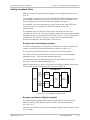
Configuring the Clock Source
Clocking for ASMi-52CQ can come from four different sources:
4-2
•
Station – clocking comes from the LRS-24 system clock
•
External – clocking comes from the user port, service, or DTE interface
•
Receive – clocking is taken from the DSL line
Configuring the Modem
ASMi-52CQ Ver. 2.12
Installation and Operation Manual
•
Chapter 4 Configuration
Internal – clocking comes from its internal oscillator (also known as master
clocking).
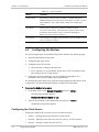
Figure 4-1 illustrates the various clock sources.
Figure 4-1. ASMi-52CQ Clock Sources
The clock source of each line in ASMi-52CQ can be configured separately with the
following restrictions:
³
•
External clocking cannot be used for Ethernet.
•
When receive clocking is configured for one line, all lines must use receive
clocking
•
When using ASMi-52CQ as CPE it must be configured to receive clocking.
To configure the clock source:
•
In the Modem Setup menu, move the cursor to CLOCK SOURCE LOC/REM field
by pressing <Tab> and select the clock source for the selected modem.
Configuring the DTE Interface
To configure the ASMi-52CQ DTE interface (serial or E1/T1), refer to the
appropriate section below. See Appendix C for explanations of the parameters.
Configuring the Serial Interface
³
To configure the serial interface:
•
In the Modem Setup menu, move the cursor to DATA RATE field by pressing
<Tab> and select the desired transmission rate by pressing <F> or <B>.
Configuring the E1 Interface
³
To configure the E1 parameters:
1. In the Modem Setup menu, move the cursor to NEXT PARMETERS (E1) field by
pressing <Tab> and select YES by pressing <F> or <B>.
The Modem Setup menu: E1 Parameters screen appears.
2. Configure the following E1 parameters:
ASMi-52CQ Ver. 2.12
Framed mode
Configuring the Modem
4-3
Chapter 4 Configuration
Note
Installation and Operation Manual
• If the opposite modem is E1, then the Framed Mode value can be G732N,
G732S Transparent, or Unframed.
• If the opposite modem is Serial DTE or LAN, then the Framed Mode value can
be G732N, or Unframed
• If Frame Mode is Unframed, then all the rest of the parameters are disabled.
Sync mode
CRC-4
Idle Code
Timeslot Assign
Unit Identical Set
First timeslot for remote E1 – define the first timeslot for the remote E1
unit.
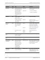
Configuring the T1 Interface
1. In the Modem Setup menu, move the cursor to NEXT PARMETERS (T1) field by
pressing <Tab> and select YES by pressing <F> or <B>.
The Modem Setup menu: T1 Parameters screen appears.
2. Configure the following T1 parameters:
Framing mode
Line coding
Idle Code
Timeslot Assign
Unit Identical Set
Receive gain
Interface
Transmit signal mask
Fbit configuration.
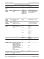
Configuring the Line Parameters
³
To configure the Line parameters:
1. If you have configured E1/T1 parameters, press <ESC> to return to the Main
menu, and then repeat the steps above to access the Modem Setup menu.
2. In the Modem Setup menu, move the cursor to NEXT PARMETERS (LINE) field
by pressing <Tab> and select YES by pressing <F> or <B>.
The Modem Setup menu: Line Parameters screen appears.
3. Configure the following line parameters:
4-4
Power backoff
Snext margin, if line probing is set to adaptive
Configuring the Modem
ASMi-52CQ Ver. 2.12
Installation and Operation Manual
Chapter 4 Configuration
Current margin, if line probing is set to adaptive
Power spectral density (line probing set to fixed only)
Line probing
Transmission mode
Loop attenuation threshold
SNR margin threshold.
4.3
Memory Downloading
CPU and Memory Elements
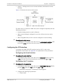
Flash Memory
The ASMi-52CQ flash includes the following elements:
•
•
•
•
•
•
Boot flash memory – Contains the Boot program, essential for the modems
initial operations.
Flash memory – Contains the application program in a compressed state. The
boot program decompresses the application to the DRAM.
DRAM – Contains the application while it runs, and all the data and variables
the program requires for operation.
Peripherals – Include the SHDSL chipset, the LEDs and other on-board
components. The CPU can access these components.
CPU – The main processing unit of the modem – responsible for all control,
monitoring and operation of the modem.
FPGA – Responsible for glue logic and proprietary timing implementations.
The CPU first runs the Boot program from the Boot flash. The Boot program then
decompresses one of the two compressed application programs stored in the
Flash memory to the DRAM. The uncompressed program runs from the DRAM,
and loads the FPGA. This enables the CPU to access all the peripheral devices and
begin to run the modem.
ASMi-52CQ Ver. 2.12
Memory Downloading
4-5
Chapter 4 Configuration
Installation and Operation Manual
Figure 4-2. Memory Map
Download Procedure
The download function updates the latest software version that exists in the
CM-2. The new software is stored (replacing the oldest version stored) in the
Flash memory.
The CM-2 modules with software version 4.0 store up to three different software
release files. Previous CM-2 modules store a single software release file for
ASMi-52CQ.
New software releases are distributed as *.img files.
The software download procedure consists of the following stages:
•
Software download to the CM-2 module from the management station using
TFTP or XMODEM protocol (see Downloading via LAN and Downloading via
XMODEM sections).
Software download from the CM-2 to a single ASMi-52CQ card (see Downloading
via CM-2 Flash section) or to all the ASMi-52CQ modems simultaneously (see
Downloading a New Software Version to All the ASMi-52CQ Modems section).
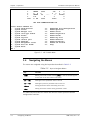
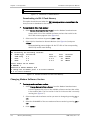
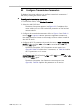
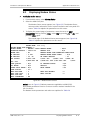
Defining Type of Download
³
To define type of download:
1. From the Main Menu, select Modem Download.
2. Select the ASMi-52CQ slot and define the modem that you intend to
configure.
The screen shown in Figure 4-3 appears.
3. Select a number for type of download.
4-6
Memory Downloading
ASMi-52CQ Ver. 2.12
Installation and Operation Manual
Chapter 4 Configuration
DOWNLOAD MAIN MENU
1. Modem Download via LAN
2. Modem Download via XMODEM
3. Modem Download via CM2 FLASH
4. Modem Download via MODEM FLASH
5. Change Modem Software Version
6. View Existing Versions of Modem
Enter download option number ___>
Figure 4-3. Download Main Menu
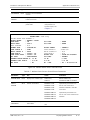
Downloading via LAN
When this option is selected, the new software file is transferred from a server to
the CM-2, using the TFTP protocol.
³
To download via LAN:
1. From the Modem Download menu, select Modem Download via LAN.
The Download via LAN menu appears (see Figure 4-4).
2. Enter IP address of TFTP server and file name.
3. Press <Enter>.
The file is transferred via the Ethernet connection of the CM-2, using the
TFTP protocol.
Download via LAN
IP Address of TFTP server: 000.000.000.000
File name: Insert file name for download
Remote modems: N/A
Figure 4-4. Download via LAN Menu
Downloading via XMODEM
When this option is selected, the new software file is transferred from a server to
the CM-2, using the XMODEM protocol.
³
To download via XMODEM:
1. From the Download Main menu, select CM2 or Modems Download via
XMODEM.
2. After typing the parameter data, press <Enter> to start the download
process.
3. Start the XMODEM server, when CM-2 displays the following message:
The CM-2 is waiting to the XMODEM data. Start the process
within one min.
If after one minute the XMODEM server has not connected properly to the
CM-2, the message The download action has failed appears.
ASMi-52CQ Ver. 2.12
Memory Downloading
4-7
Chapter 4 Configuration
Installation and Operation Manual
Download via XMODEM
Remote modems: N/A
Figure 4-5. Download via XMODEM Menu
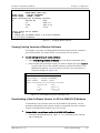
Downloading via CM-2 Flash Memory
This option should be used when the CM-2 already contains a new software file
that you want to download to the modem.
³
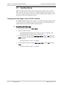
To download via CM-2 Flash memory
1. Select Modem Download via CM2 FLASH from the Modem Download menu.
A menu with a list of the available software versions that reside in the
CM-2 flash memory appears (see Figure 4-6).
2. Select one of the versions by pressing <F> or <B>.
3. Select N/A for Download to Remote Modems (see Figure 4-6) and press
<Enter>.
The downloading process begins. All the TST LEDs of the corresponding
ASMi-52CQ module start blinking.
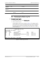
MODEMS DOWNLOAD via CM2 FLASH
CM2 containing the following versions:
ID
Modem Type
Version No.
1
ASMi-52CQ
0.2
2
NULL
0.0
3
NULL
0.0
Date
2000-6-6
0-0-0
0-0-0
Size
230k
0k
0k
Location
FLASH2
EMPTY
EMPTY
Please choose the ID number
ID NUMBER: 1
Download to Remote Modems: N/A
to change the ID number press f to scroll forward
or b to scroll backward
Figure 4-6. Modem Download via CM2 Flash Memory
Changing Modem Software Version
³
To change modem software version:
1. Select Change Modem Software Version from the Modem Download menu.
A screen appears with a list of the available software versions that reside
in the modem flash. The first version in the list is the one that is currently
running (see Figure 4-7).
2. Select modem which software version you want to change by pressing <F> or
<B>.
3. Select the ID NUMBER of the new modem software version by pressing <F> or
<B>.
4. Press <Enter>.
4-8
Memory Downloading
ASMi-52CQ Ver. 2.12
Installation and Operation Manual
Chapter 4 Configuration
CHANGING MODEM’S VERSION
MODEM NAME: ASMi-52CQ
MODEM STATUS : MASTER PERMANENT
SELECT MODEM : MODEM 1 LOCAL
Modem containing the following versions:
ID
Version No.
Date
1
0.2
2000-6-6
2
0.2E1
2001-2-22
3
0.0
0-0-0
Please choose the ID number
ID NUMBER: 1
to change the ID number press f to scroll forward
or b to scroll backward
Figure 4-7. Changing Modem Version
Viewing Existing Versions of Modem Software
This display is the same as Change Modem Software Version screen, however it
can only be viewed. You cannot select a new version with this option.
³
To view existing versions of modem software:
1. Select View Existing Versions of Modem from the Modem Download menu.
2. Select modem which software version you want to display and press <Enter>.
A screen with a list of the available software versions that reside in the
MODEM flash appears. The first version in the list is the version that is
currently running (see Figure 4-8).
VIEW MODEM VERSIONS ON MODEM’S FLASH
MODEM NAME: ASMi-52CQ
MODEM STATUS : MASTER PERMANENT
SELECT MODEM : MODEM 1 LOCAL
Modem containing the following versions:
ID
Version No.
Date
1
0.2
2000-6-6
2
0.2E1
2001-2-22
3
0.0
0-0-0
Figure 4-8. View Modem Versions in Modem Flash
Downloading a New Software Version to All the ASMi-52CQ Modems
To download a new software version to all the ASMi-52CQ modems, use the
procedures described in the previous sections to download the same software
version to all ASMi-52CQ modems in the LRS-24 hub.
³
To download a new software version to all ASMi-52CQ modems:
•
ASMi-52CQ Ver. 2.12
From the Download Main menu, type 1, 2, or 3, according to the required
type of download.
Memory Downloading
4-9
Chapter 4 Configuration
4-10
Memory Downloading
Installation and Operation Manual
ASMi-52CQ Ver. 2.12
Chapter 5
Troubleshooting and
Diagnostics
This chapter describes the ASMi-52CQ diagnostic functions, which include:
•
Diagnostic tests (loopbacks, LEDs test)
•
Status indications, alarms
•
SHDSL performance diagnostics
•
Troubleshooting procedures.
5.1
Introduction
ASMi-52CQ offers diagnostics for troubleshooting:
•
V.54 loopbacks – Local analog and remote digital loopbacks needed to isolate
a failure to a particular element of the transmission system
•
Alarm buffer – Contains alarm messages regarding the status of the
transmission system.
All diagnostics options can be invoked from the RADview SNMP management tool
or an ASCII terminal. A combination of the above diagnostics tests is also
possible. Then, examine the alarm buffer messages for any transmission error or
configuration mismatch. When you set a test for one modem of ASMi-52CQ, no
parameters for this modem can be changed, except to disable the specific test.
Once the line is disconnected, or one of the units is reset, the diagnostics stop.
Note
In all diagnostics functions the clock mode remains unchanged, in order to avoid
interfering with the other channels.
ASMi-52CQ Ver. 2.12
Introduction
5-1
Chapter 5 Troubleshooting and Diagnostics
5.2
Installation and Operation Manual
Monitoring Performance
Displaying SHDSL Performance
ASMi-52CQ has capabilities for collection of SHDSL parameters performance
diagnostics. The statistics are accessed via the RADview SNMP management
parameters tool. The parameters are listed in Table 5-1.
Table 5-1. ASMi-52CQ Performance Monitoring Parameters for Current Time
Display
Description
Current ES
Number of errored seconds in which one or more CRC (Cyclic Redundancy Check)
error events occurred during the current interval. This value is updated every second.
Current UAS
Number of unavailable seconds in which a failed signal occurred during the current
interval. This value is updated every second.
Current SES
Number of severely errored seconds in which 832 or more CRC error events occurred
during the current interval. This value is updated every second.
Current LOSWS
Number of seconds with loss of sync word during the current interval. This value is
updated every second.
Current total CRC
Number of CRC error events recorded since the last time the register was cleared.
Current TIMER
Time in seconds from the beginning of the interval. This value is updated every
second.
Displaying E1/T1 Performance
When ASMi-52CQ includes G.704 E1/T1 port, the modem has capabilities for
collection of the E1/T1 performance diagnostics. The statistics are accessed via
the RADview SNMP management parameters tool. Statistics collection depends
on the use of the CRC-4 function:
•
CRC-4 Enabled (E1), ESF Framing (T1)
When the CRC-4 function is enabled or when T1 is in ESF Framing mode, it is
possible to monitor the data transmission performance end-to-end. The error
detection is derived from the data payload by performing a cyclic redundancy
check (CRC). The resulting CRC checksum is transmitted in addition to the raw
data bits. The receiving end recalculates the checksum and compares the
results with the received checksum: any difference between the two
checksums indicates that one or more bits are contained in the current data
block being evaluated.
•
CRC-4 Disabled (E1), SF Framing (T1)
When the CRC-4 option is disabled or when T1 is in SF Framing mode, ASMi52CQ does not support the capabilities listed above. However, the modem is
capable of providing statistics of the bipolar violations.
5-2
Monitoring Performance
ASMi-52CQ Ver. 2.12
Installation and Operation Manual
Chapter 5 Troubleshooting and Diagnostics
Table 5-2. E1/T1 Performance Monitoring Parameters
Display
Description
BPV last minute
Number of BPV events detected in the last minute
BPV worst minute
Number of BPV events detected in the worst minute
Sync/Sync Loss
(E1/T1 status)
Framed operation – loss of frame alignment, unframed operation – loss of signal
CRC error events
Number of CRC error events recorded since the last time the register was cleared.
CRC avg error events
The average number of CRC events per second.
Current ES
Number of errored seconds in which one or more CRC error events occurred during
the current interval. This value is updated every second.
Current UAS
Number of unavailable seconds in which a failed signal occurred during the current
interval. This value is updated every second.
Current SES
Number of severely errored seconds with 832 or more CRC error during the current
interval. This value is updated every second.
Current BES
Number of seconds with 2 to 831 CRC events during the current interval. This value
is updated every second.
Current LOFC
Number of loss of frame events measured during the current interval.
Current CSS
Number of seconds with one or more controlled slip events measured during the
current interval.
Current TIMER
Time in seconds from the beginning of the interval. This value is updated every
second.
24 hour ES
Number of ES measured during the last 24 hours. This value is updated every
15 minutes.
24 hour UAS
Number of UAS measured during the last 24 hours. This value is updated every
15 minutes.
24 hour SES
Number of SES measured during the last 24 hours. This value is updated every
15 minutes.
24 hour BES
Number of BES measured during the last 24 hours. This value is updated every
15 minutes.
24 hour LOFC
Number of LOFC measured during the last 24 hours. This value is updated every
15 minutes.
24 hour CSS
Number of CSS measured during the last 24 hours. This value is updated every
15 minutes.
Current degrade
minute
Number of degraded minutes, in which the bit error rate exceeded 1×10 , in the
24 intervals
Number of 15 min. intervals the device has been working since power up, the value
is from 0 to 96.
Last 24 degrade
minutes
The last 24 hour count of the degraded minutes. This value is updated every
24 hours.
ASMi-52CQ Ver. 2.12
−6
current interval. This value is updated every 1 minute.
Monitoring Performance
5-3
Chapter 5 Troubleshooting and Diagnostics
5.3
Installation and Operation Manual
Handling Alarms
ASMi-52CQ alarm buffer stores system alarm records, which can be viewed on
either an ASCII terminal (see below) or an SNMP management tool. When one or
more alarm records appear in the buffer, the front panel ALM LED lights up. After
the alarm is cleared, the ALM LED turns off.
Viewing Alarm Messages from an ASCII Terminal
The MODEM ALARM STATUS screen (Figure 5-1) enables viewing messages stored
in the alarm buffer of ASMi-52CQ and remote modems. The screen also shows
synchronization loss and DTE loopback signaling states.
³
To view the ASMi-52CQ alarms:
1. From the Main menu, select Alarm Status.
2. Select the ASMi-52CQ slot.
The MODEM ALARM STATUS screen shown in Figure 5-1 appears. This
screen displays the general alarms of ASMi-52CQ.
3. To view E1/T1/T1 alarms, change Next Alarm (E1/T1) value to ON and press
<Tab> to display next alarm screen (available only for ASMi-52CQ with G.704
E1/T1 interface).
The screen shown in Figure 5-2 appears.
4. To view SHDSL line alarms, change Next Alarm (LINE) value to ON and press
<Tab>.
The screen shown in Figure 5-3 appears.
5-4
Handling Alarms
ASMi-52CQ Ver. 2.12
Installation and Operation Manual
Chapter 5 Troubleshooting and Diagnostics
MODEM ALARM STATUS
MODEM NAME : ASMi-52CQ
DEFINE MODEM PORT NUMBER
: 1
SELECT MODEM
: MODEM 1 LOCAL
LINE DISCONNECT
: OFF
REMOTE MODEM POWER OFF : OFF
: OFF
TRANSMIT CARRIER
: OFF NVRAM FAILED
RECEIVE CARRIER
: OFF PROP PROTOCOL FAILED
LLB BY DTE
: OFF SOFTWARE DWL IN PROCESS
RLB BY DTE
: OFF INCOMPATIBLE CONNECTORS
SYNC LOSS
A
: ON SYNC LOSS
B
CRC6 ERR EXC A
: OFF
OFF
CONFIGURATION MISMATCH : OFF PHASOR OVERFLOW EXC
ILLEGAL EXTERNAL CLOCK SOURCE
CONNECTION
: OFF
NO MANAGEMENT LINK
: OFF XILINX FAILED
NO MODEM PORT (IR)
: OFF LAN NOT CONNECTED
NO FIBER INTERFACE
: OFF NO EXT CLK INPUT
IR RATE MISMATCH
: OFF ILL. CLK-ERR
SELF TEST FAILED
: OFF OLD REM VERSION
MINOR ALARM-AIS-ELEC : OFF AIS-OPT
MAJOR ALARM-LINE DISCON.-ELEC
OPT
: OFF
NEXT ALARMS(E1/T1)
: OFF NEXT ALARMS(SHDSL)
STUFFING OVERFLOW EXC
: OFF
: OFF
: OFF
: OFF
: OFF
CRC6 ERR EXC B
:
: OFF
: OFF
WRONG
: OFF
: OFF
: OFF
: OFF
: OFF
: OFF
: OFF
LINE DISCON. –
: OFF
Figure 5-1. Modem Alarms Status Screen
MODEM ALARM STATUS
MODEM NAME : ASMi-52CQ
DEFINE MODEM PORT NUMBER
: 1
SELECT MODEM
: MODEM 1 LOCAL
E1 SIGNAL LOSS
: OFF E1 BPV ERR. EXC
E1 FRAME SLIP EXC
: OFF E1 EXECIVE BPV
E1 CRC4 ERR. EXC
: OFF E1 EXECIVE ERR. RATIO
E1 AIS OCCURED
: OFF E1 AIS RED ALARM
E1 RED ALARM
: OFF E1 CRC MF ERR. EXC
E1 YELLOW ALARM
: OFF E1 SYNC LOSS
E1 LOCAL MF
: OFF E1 REMOTE MF
E1 REM SIGNAL LOSS
: OFF E1 TS RATE MISMATCH
E1 TS NOT COMP
: OFF E1 TS NOT *128
: OFF
: OFF
: OFF
: OFF
: OFF
: OFF
: OFF
: OFF
: OFF
Figure 5-2. Modem Alarm Status Example (E1 Alarms)
ASMi-52CQ Ver. 2.12
Handling Alarms
5-5
Chapter 5 Troubleshooting and Diagnostics
Installation and Operation Manual
MODEM ALARM STATUS
MODEM NAME : ASMi-52CQ
DEFINE MODEM PORT NUMBER
: 1
SELECT MODEM
: MODEM 1 LOCAL
LOOP ATTN A
: OFF LOOP ATTN B
SNR MARGIN A
: OFF SNR MARGIN B
LOSW FAIL A
: OFF LOSW FAIL B
INCOMPATIBLE DATA RATE : OFF INCOMPATIBLE PSD
WIRE NOT COMPATIBLE
: OFF
:
:
:
:
OFF
OFF
OFF
OFF
Figure 5-3. Modem Alarm Status (SHDSL Alarms)
Table 5-5 lists the ASMi-52CQ alarms in alphabetical order. Table 5-4 explains
how to use alarms for troubleshooting.
Table 5-2. ASMi-52CQ Alarms and Warnings
5-6
Terminal Message
Alarm Type
Description
Severity
LINE DISCONNECT
General
The line has been disconnected
Major
REMOTE MODEM POWER
OFF
General
Remote modem power disconnected
Major
LLB BY DTE
General
Local loopback has been activated by
physical connector (not relevant for units
with X.21 DTE interface only)
Warning
SOFTWARE DWL IN
PROGRESS
General
Software download is in progress
Warning
RLB BY DTE
General
Remote loopback has been activated by
physical connector (not relevant for units
with X.21 DTE interface only)
Warning
SYNC LOSS LINE A
SHDSL
SHDSL line A is nor synchronized
Major
CRC6 ERR EXC A
SHDSL
Excessive CRC-6 errors have been detected
on SHDSL line A
Minor
ILLEGAL EXTERNAL CLOCK
SOURCE
General
External clock source failed.
Major
NO MANAGEMENT LINK
General
Failure of inband management via the EOC
Major
NO MODEM PORT (IR)
General
The LRSI interface module is absent
Major
SELF TEST FAILED
General
Failure occurred during self-test
Major
PROP PROTOCOL FAILED
General
The proprietary embedded management
channel between ASMi-52CQ and remote
devices has failed
Major
MINOR ALARM-AIS-ELEC
DTE
AIS and loss of frame alignment are
detected
Minor
E1/T1 SIGNAL LOSS
DTE
E1/T1 loss is detected at the DTE port
Minor
E1/T1 BPV ERR EXC
DTE
E1/T1 bipolar violation errors exceed
threshold
Major
Handling Alarms
ASMi-52CQ Ver. 2.12
Installation and Operation Manual
Chapter 5 Troubleshooting and Diagnostics
Terminal Message
Alarm Type
Description
Severity
E1/T1 FRAME SLIP EXC
DTE
E1/T1 frame slips exceed the threshold
E1/T1 EXCESIVE BPV
DTE
Bipolar violations rate exceeds 1×10
during the last 1000 seconds
E1 CRC-4 EXC
DTE
CRC-4 errors exceed the threshold
Minor
-6
Major
Major
-3
E1/T1 EXCESIVE ERR RATIO
DTE
The bit error rate of the link exceeds 10
E1/T1 AIS OCCURED
DTE
AIS is detected at the E1/T1 port
Major
E1/T1 AIS RED ALARM
DTE
AIS and loss of frame alignment are
detected
Major
E1/T1 RED ALARM
DTE
E1/T1 loss of frame synchronization
occurred (shown on terminal)
Major
E1 SYNC LOSS
DTE
E1 loss of frame synchronization occurred
(shown in CM2)
Major
E1 CRC MF ERR. EXC
DTE
CRC errors detected in the frame
synchronization signal exceeded the
threshold
Major
E1/T1 YELLOW ALARM
DTE
Local loss of frame synchronization
Major
E1/T1 REMOTE SIGNAL
LOSS
DTE
E1/T1 signal loss is detected at remote
ASMi-52
Major
E1/T1-TS NOT RATE COMP
SHDSL
Current line rate does not support the
number of assigned E1/T1 timeslots
Minor
E1/T1 TS NOT X128
SHDSL
Line A loop attenuation has exceeded the
alarm threshold
Minor
LOOP ATTN A
SHDSL
Line B loop attenuation has exceeded the
alarm threshold
Minor
SNR MARGIN A
SHDSL
Line A signal-to-noise margin has
exceeded the alarm threshold
Minor
LOSW FAILURE A
DTE
Loss of Sync Word is detected on line A
Major
INCOMPATIBLE DATA RATE
DTE
Mismatch in the line rate and data rate.
Applicable for the ASMi-52CQ units with
V.35 interface operating in adaptive rate
mode
Major
ASMi-52CQ Ver. 2.12
Major
Handling Alarms
5-7
Chapter 5 Troubleshooting and Diagnostics
5.4
Installation and Operation Manual
Troubleshooting
Using LEDs
You may locate and correct some failures by using the front panel LEDs (see
Table 5-3). Table 5-4 lists the alarm buffer messages, seen on the ASCII terminal
or the RADview SNMP management tool.
Table 5-3. Using LEDs for Troubleshooting
Symptom
Possible Failure
Corrective Action
POWER LED is OFF
Blown fuses
Replace fuses (remove ASMi-52CQ from
the hub)
SYNC is red (modem is not
synchronized)
Line connection
between modems
Check line and line connection between
modems
Modems are synchronized but
DATA LED is OFF (information is not
transferred)
Modem to DTE
connection
Check connection between modem and
DTE
See Table 5-4
ALM LED is On
Using the Alarm Buffer
³
To use the alarm buffer for troubleshooting:
1. When the ALM LED is ON, connect the RADview management tool or an ASCII
terminal to view the alarm buffer messages.
2. Enter the Modem Alarm Status screen and watch the alarm states.
ON indicates an active alarm.
Table 5-4. Using Alarm Buffer for Troubleshooting
Symptom
Possible Failure
Corrective Action
ALM LED is ON and SYNC LOSS
LINE A alarm is stored in the
alarm buffer
Line between modems is
not properly connected
Verify and connect the line properly; verify
the units’ clock type
ALM LED is ON and NO
MANAGEMENT LINK alarm is
stored in the alarm buffer
Line between modems
has exceeded its
maximum range; or the
line quality is poor
Replace unit or contact RAD’s Technical
Support
ALM LED is ON and
SELF TEST FAILED alarm is stored
in the alarm buffer
Hardware failure
Replace unit
ALM LED is ON and
NO MODEM PORT alarm is stored
in the alarm buffer
Digital interface is
missing, or digital
interface is not supported
by modem
Mount required digital interface on the
ASMi-52CQ module
5-8
Troubleshooting
ASMi-52CQ Ver. 2.12
Installation and Operation Manual
5.5
Chapter 5 Troubleshooting and Diagnostics
Testing ASMi-52CQ
The user-controlled test functions of ASMi-52CQ consist of the loopback tests,
BER test and LEDs tests. The purpose of these tests is to determine the source of
a break in the data flow.
The Modem Diagnostic screen enables you to configure loopback connections,
and initiate LEDs test.
Initiating Loopback and LED Tests
³
To initiate loopback or LED tests:
1. From the Main menu, select Modem Diagnostics.
2. Select the ASMi-52CQ slot.
The Modem Diagnostics menu appears.
MODEM DIAGNOSTICS
MODEM NAME: ASMi-52CQ
DEFINE MODEM PORT NUMBER
: 1
MODEM STATUS
: MASTER PERMANENT
SELECT MODEM
: MODEM 1 LOCAL
LOOP & BERT
: CANCEL LOOP TIMEOUT(MIN)
: N/A
REMOTE DIG ENABLE
: N/A
LOOP TIMEOUT(0-4095 MIN): 5
BERT RESULTS
: 0.0 E- 00
LED TEST
: OFF
LOCAL LOOP BACK
: DISABLE
REMOTE LOOP BACK
: DISABLE
REMOTE DIG
: N/A
ENABLE TEST FROM REM MODEM
: N/A
BERT ERR INJECTION
: NO ERR
BERT PATTERN
: MARK
BERT CLEAR COUNTERS
: NO
Figure 5-4. Modem Diagnostic Menu
Rows in bold in the figures indicate parameters applicable to ASMi-52CQ and
standalone modems. Additional, non-bolded parameters listed on a screen apply
to other modems installed in the LRS-24 hub.
The Modem Diagnostics screen fields and the options for each field are explained
in Table 5-5.
ASMi-52CQ Ver. 2.12
Testing ASMi-52CQ
5-9
Chapter 5 Troubleshooting and Diagnostics
Installation and Operation Manual
Table 5-5. Modem Diagnostics Parameters
Parameter
Type
Use
Value
Indication
MODEM NAME
Read
Identifies the modem
type which status is
being viewed or
modified
ASMi-52CQ
Master ASMi-52CQ
ASMi-52
Standalone ASMi-52 remote
modem
MODEM
STATUS
Read
For viewing
configuration mode
MASTER PERMANENT
The modem controls its own
configurable parameters
SELECT
MODEM
Write
Selects the modem
which diagnostic
parameters you set
using this screen.
MODEM1
MODEM2
MODEM3
MODEM4
LOCAL
LOCAL
LOCAL
LOCAL
Operational parameters will be
set for one of the modems
installed in the LRS-24 chassis
MODEM1
MODEM2
MODEM3
MODEM4
REMOTE
REMOTE
REMOTE
REMOTE
Operational parameters will be
set for one of the remote
modems
LOOP & BERT
Write
Selecting the loopback
operation
ANA
Local loopback is initiated
REM
Remote loopback is initiated
CANCEL
Diagnostic loopback is cancelled
Note: Activating remote loopback from a remote modem is available for ASMi-52 modems with software
revision 1.12 or higher.
LOOP TIMEOUT
Write
Sets the period of time
after which the LLB
automatically
deactivates
0–4095 min
Note: When activating LLB on
the remote modem, the “0”
value of the LOOP TIMEOUT
parameter is not available.
LED TEST
Write
Initiating LED test
ON
OFF
All LEDs turn on for 3 secs.
BERT PATTERN
Write
Sets the BERT pattern
2E15-1
MARK
SPACE
ALTERNATE
When a test is active, no other test can be activated for the current modem. For
details regarding loopback definitions, refer to Section 5.5.
When setting a loopback connection from the terminal, both the SELECT MODEM
and LOOP & BERT fields determine the transmission path. For example, a remote
loopback (REM) from the remote (ASMi-52 standalone) modem sets a digital
loopback in the local modem (see Figure 5-5).
5-10
Testing ASMi-52CQ
ASMi-52CQ Ver. 2.12
Installation and Operation Manual
Chapter 5 Troubleshooting and Diagnostics
Setting Loopback Tests
ASMi-52CQ supports the local analog loopback, remote digital loopbacks as per
ITU V.54.
V.54 loopback connections are set from the RADview SNMP management tool or
from an ASCII terminal (see Section 5.2) The TST LED on the front panel of the
local unit lights up and remains lit while the loopback is being run.
The loopback is activated separately for each modem on the ASMi-52CQ card;
therefore, you can run loopback for different modems on the card
simultaneously.
The loopback test runs until the timeout period has passed or the test is
cancelled (see Table 5-5). You cancel running a loopback from the RADview SNMP
management tool or from an ASCII terminal (see Section 5.2). Once a loopback is
cancelled, the TST indicators turn off. In case of the LLB, synchronization
between the modems is restored within a few minutes.
Running the Local Analog Loopback
The local analog loopback (LLB) checks the performance of the local ASMi-52CQ
modem, the local DTE and connection between them (see Figure 5-5).
The LLB can be performed separately on the local and remote modems.
LLB of the local unit is activated either from the terminal or from the SNMP
management tool. LLB is activated separately per port.
LLB of the remote unit is activated per port from the remote DTE, from the
terminal, or from the SNMP management tool.
ASMi-52CQ allows you to set the LLB timeout causing the loopback to deactivate
automatically after the desired period of time (see Table 5-5).
Local ASMi-52CQ
Data
Clock
Transmit
Glue
Logic
Local
DTE
Line
Interface
Data
Clock
Receive
Figure 5-5. Local Analog Loopback (LLB)
Running the Remote Digital Loopback
The remote digital loopback (RLB) checks the performance of both the local
ASMi-52CQ and remote ASMi-52 modems, and the lines connecting them
(see Figure 5-6).
RLB can be activated from the remote standalone ASMi-52 with software revision
1.12 or higher.
ASMi-52CQ Ver. 2.12
Testing ASMi-52CQ
5-11
Chapter 5 Troubleshooting and Diagnostics
Installation and Operation Manual
Local ASMi-52CQ
Remote ASMi-52
Data
Clock
Transmit
Receive
Glue
Logic
Local
DTE
Line
Interface
Glue
Logic
Line
Interface
Remote
DTE
Data
Clock
Receive
Transmit
Figure 5-6. Remote Digital Loopback (RLB)
Running the Bit Error Rate Test (BERT)
It is possible to generate BERT+RLB or BERT tests (from both CO and CPE) in E1
and DTE Serial units. These tests can be set only if there is a connection to the FE
unit. Both tests (BERT+RLB and BERT) check the performance of the SHDSL lines
connecting the local and remote units and can be activated opposite the remote
standalone ASMi-52 with software revision 2.12 or higher. Figure 5-7 and
Figure 5-8 show the BERT+RLB test and BERT test, respectively.
Local ASMi-52CQ
Line
Interface
Data
Clock
Remote ASMi-52
Transmit
Receive
PRBS
Generator
Glue
Logic
Local
DTE
Glue
Logic
RLB
Data
Clock
Line
Interface
Remote
DTE
BERT
Receiver
Receive
Transmit
Figure 5-7. Remote Digital Loopback + BERT Test
Local ASMi-52CQ
Line
Interface
Data
Clock
Remote ASMi-52
Transmit
PRBS
Generator
DSL
Transmit
Line
Interface
Glue
Logic
Local
DTE
Data
Clock
Receive
Receive
BERT
Receiver
Glue
Logic
BERT
Receiver
DSL
Receive
PRBS
Generator
Remote
DTE
Transmit
Figure 5-8. BERT Test
5-12
Testing ASMi-52CQ
ASMi-52CQ Ver. 2.12
Installation and Operation Manual
Chapter 5 Troubleshooting and Diagnostics
The following are the BERT test patterns that can be selected:
•
2E15-1
•
Mark
•
Space
•
Alternate
BERT has a possible Single Error injection only.
The BERT performance counters are as follows:
•
BERT Error bits – the total number of bit errors detected
•
BERT run time – the total time the test is running in seconds
•
Bert error seconds – the total number of seconds in which errors have been
detected – in seconds
•
BERT Sync Loss – the number of times Sync Loss was detected since BERT
started to run
•
BERT result – the number of error bits divided with the total number of data
bits. This item holds 1 byte for the exponent and 2 bytes for the mantissa
holding 1 byte before the period and 1 byte after the period
•
BERT Sync Loss state – the Sync Status while BERT runs. The BERT Sync Loss
state has the following values:
•
SyncLoss = OFF
Sync = ON
BERT sync run time – the total number of seconds in which sync have been
detected – in seconds.
5.6
Frequently Asked Questions
Question: Why can’t I access some fields in the CM-2 Terminal Management
screens?
Answer: In the menus of CM-2, there are some parameters you CAN change in
each menu, and there are some parameters that you can NOT change in each
menu.
This is because the CM-2 manages many different modems, and at RAD we
designed one single interface for all the modem cards inside the LRS-24, no
matter which modem is being managed. That is why you will see that some
parameters are inaccessible for you (because they are accessible for other
modems, not ASMi-52CD, for example).
Please remember to navigate the menus via the TAB key, and to change values by
pressing the "f" (forward) key, and the "b" (backward) key. Press ‘Enter’ to select
the desired value.
Question: How does LRS-24 manage ASMi-52 cards?
ASMi-52CQ Ver. 2.12
Frequently Asked Questions
5-13
Chapter 5 Troubleshooting and Diagnostics
Installation and Operation Manual
Answer: The LRS-24 manages ASMi-52CD and ASMi-52CQ cards like any other Imode modem. This means that there are no separate IP addresses for each card
in the LRS, and the SNMP agent your NMS communicates with is the CM-2, not
the modem itself.
5.7
Technical Support
Technical support for this product can be obtained from the local distributor from
whom it was purchased.
For further information, please contact the RAD distributor nearest you or one of
RAD's offices worldwide. This information can be found at www.rad.com. (Offices
– About RAD > Worldwide Offices; Distributors – Where to Buy > End Users).
5-14
Technical Support
ASMi-52CQ Ver. 2.12
Appendix A
Pinouts
A.1
LRSI-F-18 and LRSI-F-19 Connections
DCE Connector Pinout for LRSI-F-18 and LRSI-F-19
The DCE interface of the LRSI-F-18 and LRSI-F-19 modules terminates in a 68-pin
SCSI connector (see Table A-1 for connector pinout).
Table A-1. Pin Assignment of the DCE Connector for LRSI-F-18 and LRSI-F-19
Type
Data
Ground
Connector
Control
RS-530
X.21
34-Pin
DB-25
DB-15
Function
Pin
Protective Ground
A
FGND
101
1
Signal Ground
B
SGND
102
7
Transmitted Data
P
TD(A)
103
S
TD(B)
R
Received Data
Request to Send
Timing
V.35
Carrier Detect
Pin ID
CH-1
CH-2
CH-3
CH-4
1 SHIELD
8
24
36
52
AB
8
GND
18
34
46
62
2
BA(A)
2
T(A)
10
22
38
50
103
14
BA(B)
9
T(B)
14
26
42
54
RD(A)
104
3
BB(A)
4
R(A)
3
21
49
66
T
RD(B)
104
16
BB(B)
11 R(B)
1
25
45
67
C
RTS
105
4
CA(A)
3
CA(A)
6
19
35
51
19
CA(B)
10 CA(B)
7
23
39
55
8
CF(A)
5
(A)
11
27
43
59
10
CF(B)
12 (B)
15
31
47
63
F
ID Circuit
DCD
109
Pin
Circuit
SCSI 68-pin
External Transmit
U
SCTE(A) 113
24
DA(A)
7
(A)
16
28
44
56
Clock
W
SCTE(B) 113
11
DA(B)
14 (B)
20
32
48
58
Transmit Clock
Y
SCT(A)
114
15
DB(A)
6
S(A)
4
13
57
64
AA SCT(B)
114
12
DB(B)
13 S(B)
2
17
53
68
V
SCR(A)
115
17
DD(A)
–
5
29
41
65
X
SCR(B)
115
9
DD(B)
9
33
37
61
Receive Clock
ASMi-52CQ Ver. 2.12
LRSI-F-18 and LRSI-F-19 Connections
A-1
Appendix A Pinouts
Note
Installation and Operation Manual
There are four SCSI pins that are not assigned.
Line Connector Pinout for LRSI-F-18
The line interface of the LRSI-F-18 module terminates in an RJ-11 line connector,
(see Table A-2 for the connector pinout).
Table A-2. Pin Assignment of the RJ-11 Line Connector for LRSI-F-18
Pins
ID
Function
Direction
1, 2,3
–
Not connected
–
4, 5
LINE
Bidirectional line
Input/Output
6
–
Not connected
–
A.2
LRSI-F-20 and LRSI-F-28 Connections
DCE Connector Pinout for LRSI-F-20 and LRSI-F-28
The DCE interface of the LRSI-F-20 and LRSI-F-28 terminates in a RJ-45 connector
(see Table A-3 for connector pinout).
Table A-3. Pin Assignment of the DCE Connector for LRSI-F-20 and LRSI-F-28
Pin
Name
Function
1
RX (+)
Receive Data Positive
2
RX (-)
Receive Data Negative
4
TX (+)
Transmit Data Positive
5
TX (-)
Transmit Data Negative
Line Connector Pinout for LRSI-F-28
The line interface of the LRSI-F-28 module terminates in an RJ-11 line connector,
(see Table A-4 for the connector pinout).
Table A-4. Pin Assignment of the RJ-45 Line Connector for LRSI-F-28
A-2
Pins
ID
1, 2
Line A
3
–
4, 5
Line B
LRSI-F-20 and LRSI-F-28 Connections
Function
Direction
Not connected
–
ASMi-52CQ Ver. 2.12
Installation and Operation Manual
A.3
Appendix A Pinouts
LRSI-F-21 and LRSI-F-29 Connections
DCE Connector Pinout for LRSI-F-21 and LRSI-F-29
The DCE interface of the LRSI-F-21 and LRSI-F-29 terminate in a DB-25 female
connector (see Table A-5 for connector pinout).
Table A-5. Pin Assignment of the DCE Connector for LRSI-F-21 and LRSI-F-29
Pin
Name
Function
CH-1
CH-2
CH-3
CH-4
RX (+)
Receive Data Positive
24
21
18
15
RX (-)
Receive Data Negative
11
9
6
3
TX (+)
Transmit Data Positive
23
20
17
14
TX (-)
Transmit Data Negative
12
8
5
2
Line Connector Pinout for LRSI-F-29
The line interface of the LRSI-F-29 module terminates in a RJ-45 line connector,
(see Table B-6 for the connector pinout).
Table A-6. Pin Assignment of the RJ-45 Line Connector for LRSI-F-29
Pins
ID
1, 2
Line A
3
–
4, 5
Line B
Function
Direction
Not connected
–
CBL-LRSI21/DB25/UB Cable Pinout
Splitter cable for connecting the DB-25 connector of the LRSI-F-21 interface
module to four BNC unbalanced ports. The CBL-LRSI21/DB25/UB/M cable
comprises one male DB-25 and eight male BNC connectors (see Figure A-1). The
CBL-LRSI21/DB25/UB/F cable comprises one male DB-25 and eight female BNC
connectors . Table A-7 lists the CBL-LRSI21/DB25/UB cable pinout.
ASMi-52CQ Ver. 2.12
LRSI-F-21 and LRSI-F-29 Connections
A-3
Appendix A Pinouts
Installation and Operation Manual
CH1-RX
CH1-TX
CH2-RX
CH2-TX
CH3-RX
CH3-TX
CH4-RX
CH4-TX
Figure A-1. CBL-LRSI21/DB25/UB Cable
Table A-7. CBL-LRSI21/DB25/UB Cable Pinout
DB-25
RX
CH-1
TX
RX
CH-2
TX
RX
CH-3
TX
RX
CH-4
TX
A-4
LRSI-F-21 and LRSI-F-29 Connections
BNC
23
CH1-RX
1
11
CH1-RX
2
24
CH1-TX
1
12
CH1-TX
2
20
CH2-RX
1
8
CH2-RX
2
21
CH2-TX
1
9
CH2-TX
2
17
CH3-RX
1
5
CH3-RX
2
18
CH3-TX
1
6
CH3-TX
2
14
CH4-RX
1
2
CH4-RX
2
15
CH4-TX
1
3
CH4-TX
2
ASMi-52CQ Ver. 2.12
Appendix B
Parameter List
This chapter lists:
•
Command options to manage the ASMi-52CQ modem using an ASCII terminal
•
Parameters with their values and explanations.
B.1
³
Configuring Advanced Modem Parameters
To configure advanced modem parameters:
1. From the Main menu, select Modem Operation.
2. Select the ASMi-52CQ slot.
The Modem Advanced Setup menu shown in Figure B-1 appears. When
this menu first appears, all parameters are set to either the default or
inactive state to prevent an undesired modem response.
MODEM ADVANCED SETUP
MODEM NAME:
ASMi-52CQ
DEFINE MODEM PORT NUMBER
MODEM STATUS
SELECT MODEM
1) STOP STATUS UPDATE
2) CHANGE LOCAL MODEM STATUS
3) MANAGEMENT FROM REMOTE MODEM
4) MODEM MANAGEMENT LINK
5) LOAD CONFIGURATION FROM
6) I–TYPE (FAR_END MODEM TYPE)
7) MODEM RESET
8) FACTORY RESET
9) CARD RESET
:
:
:
:
:
:
:
:
:
:
:
:
1
MASTER
MODEM 1 LOCAL
DISABLE
MASTER
NO
N/A
N/A
MODEM
YES
NO
NO
NO
Figure B-1. Modem Advanced Setup Menu
Bolded rows in Figure B-1 indicate parameters applicable to ASMi-52CQ.
Non-bolded parameters listed on the screen apply to other modems installed in
the LRS-24 chassis.
Table B-1 shows the operational parameters and options for ASMi-52CQ that can
be viewed and/or modified using this screen.
ASMi-52CQ Ver. 2.12
Configuring Advanced Modem Parameters
B-1
Appendix B Parameter List
Installation and Operation Manual
Table B-1. Modem Advanced Setup Screen Parameters
Parameter
Type
Use
MODEM NAME
Read
Viewing modem type
Value
Indication
The modem connected to the
terminal is:
ASMi-52CQ
Master ASMi-52CQ
ASMi-52
Standalone modem
N/A
MODEM STATUS
Read
Viewing modem
configuration mode
MASTER
SELECT MODEM
Write
Selecting the
modem, whose
operational
parameters are set
MODEM1
MODEM2
MODEM3
MODEM4
LOCAL
LOCAL
LOCAL
LOCAL
Operational parameters are set
for one of the local modems
installed in the LRS-24 chassis
MODEM1
MODEM2
MODEM3
MODEM4
REMOTE
REMOTE
REMOTE
REMOTE
Operational parameters are set
for one of the remote modems
STOP STATUS
UPDATE
MODEM RESET
FACTORY RESET
CARD RESET
B-2
Write
Write
Controlling status
information flow
from the modem to
CM-2
DISABLE
Enables flow of status
information from modem to CM2
ENABLE
Disables flow of status
information from modem to CM2. This may occur when CM-2
services other LRS-24 modems
and there is an overflow of
alarm messages.
Resetting the
modem line
YES
Performs reset to modem line
NO
Does not perform reset to
modem line
YES
Resets modem to default
settings
NO
Does not reset modem to
default settings
YES
Performs reset to card
NO
Does not perform reset to card
Write
Write
Resetting
parameters of card
Configuring Advanced Modem Parameters
ASMi-52CQ Ver. 2.12
Installation and Operation Manual
B.2
Appendix B Parameter List
Configure Transmission Parameters
The Modem Setup menu allows you to configure transmission parameters of
ASMi-52CQ, including line and DTE values.
³
To configure the transmission parameters:
1. From the Main menu, select Modem Parameters.
2. Select the ASMi-52CQ slot.
The Modem Setup menu appears (see Figure B-2). The Modem Setup
menu enables you to set the transmission parameters of the local and
remote modems.
3. Configure the transmission parameters. Refer to Figure B-2 and Table B-2.
Rows in bold in Figure B-2 indicate parameters applicable to ASMi-52CQ.
Non-bold parameters listed on a screen apply to other modems installed in
the LRS-24 chassis.
4. Configure the E1/T1 parameters by moving the cursor to NEXT PARMETERS
(E1/T1) field by pressing <Tab>, select YES by pressing <F> or <B>, and
pressing <Tab> again.
The Modem Setup Menu: E1/T1 Parameters screen appears (see
Figure B-3. Table B-3 explains the E1 parameters, and Table B-4 explains
the T1 parameters on this screen.
5. Configure the SHDSL line parameters by moving the cursor to NEXT
PARMETERS (LINE) field by pressing <Tab>, select YES by pressing <F> or <B>,
and pressing <Tab> again.
The Modem Setup Menu: Line Parameters screen appears (see
Figure B-4). Table B-3 explains the parameters on this screen.
ASMi-52CQ Ver. 2.12
Configure Transmission Parameters
B-3
Appendix B Parameter List
Installation and Operation Manual
MODEM SETUP
ASMi-52CQ
MODEM NAME:
DEFINE MODEM PORT NUMBER
MODEM STATUS
SELECT MODEM
SYNC/ASYNC
: N/A
NO. STOP BIT
: N/A
PARITY
: N/A
CLOCK SOURCE LOC/REM : N/A
INTERFACE
: N/A
RTS TO DCD
: N/A
OUTPUT LEVEL
: N/A
OUTPUT IMPEDANCE
: N/A
CARRIER CONTROL
: N/A
RATE ADAPTATION METHOD : N/A
LINE CODING
: N/A
T1 LINE LENGTH
: N/A
BRIDGING
: N/A
MASK SIGNAL STATUS
:
NEXT PARAMETERS(E1)
: 1
: MASTER PERMANENT
: MODEM 1 LOCAL
CHARACTER LENGTH
DATA RATE
CD SENSE
EXT SOURCE:Modem #1 PORT
RTS/CTS DELAY (0:255
DTR TO DSR
INPUT LEVEL
ohm
INPUT IMPEDANCE
ERROR CORRECTION
AIS
PHANTOM
DATA: NO
DCD : NO
: NO
:
:
:
:
:
:
:
:
:
:
:
N/A
128K
N/A
N/A
N/A)
N/A
N/A
N/A
N/A
N/A
N/A
ohm
ETHERNET MODE
: HALF-DUP
RTS : NO
TD : NO
RD: NO
TEST: NO
ERR: NO
SQ: NO
NEXT PARAMETERS(LINE):NO
Figure B-2. Modem Setup Menu
MODEM NAME: ASMi-52CQ
DEFINE MODEM PORT NUMBER: 1
MODEM STATUS
: MASTER PERMANENT
SELECT MODEM
: MODEM 1 LOCAL
FRAME MODE(E1) :
:G732N
SYNC(E1) : CCITT
IDENTICAL SET
: YES
IDLE CODE(E1): ff
TS0 :TRANSP
TS1 : DATA
TS2 : DATA
TS3 : DATA
TS6 : DATA
TS7 : DATA
TS8 : DATA
TS9 : DATA
TS12: DATA
TS13: DATA
TS14: DATA
TS15: DATA
TS18: DATA
TS13: DATA
TS20: DATA
TS21: DATA
TS24: DATA
TS25: DATA
TS26: DATA
TS27: DATA
TS30: DATA
TS31: DATA
CRC4(E1)
BALANCE
TS4 : DATA
TS10: DATA
TS16: DATA
TS22: DATA
TS28: DATA
:YES
:UNBALANCE
TS5 : DATA
TS11: DATA
TS17: DATA
TS23: DATA
TS29: DATA
Figure B-3. Modem Setup Menu: E1 Parameters
B-4
Configure Transmission Parameters
ASMi-52CQ Ver. 2.12
Installation and Operation Manual
Appendix B Parameter List
MODEM NAME: ASMi-52CQ
DEFINE MODEM PORT NUMBER: 1
MODEM STATUS
: MASTER PERMANENT
SELECT MODEM
: MODEM 1 LOCAL
POWER BACKOFF
: DISABLE
SNEXT MARGIN
: DISABLE MARGIN
CURRENT MARGIN
: DISABLE MARGIN ASYM PSD
: SYMMETRIC
LINE PROB
: FIXED
PORT CLK SOURCE : MASTER CLOCK
CONFIGURED WIRE
: 2W
TRANSMISSION MODE
: ANNEX B
ATTENUATION THRESHOLD
: 0
SNR MARGIN THRESHOLD: 0
MUX MODE
: N/A
LOW SPEED OPERATION : N/A
Figure B-4. Modem Setup Menu: Line Parameters
Table B-2. Modem Setup Parameters
Parameter
Type
Use
Value
Indication
MODEM NAME
Read
Identifies the modem
type which status is
being viewed or
modified
ASMi-52CQ
Master ASMi-52CQ
ASMi-52
Standalone ASMi-52 modem
Enables view the
modem configuration
control status
MASTER
N/A
Selects the modem,
which operational
parameters are set
MODEM1
MODEM2
MODEM3
MODEM4
LOCAL
LOCAL
LOCAL
LOCAL
Operational parameters are
set for one of the local
modems installed in the LRS24 chassis
MODEM1
MODEM2
MODEM3
MODEM4
REMOTE
REMOTE
REMOTE
REMOTE
Operational parameters are
set for one of the remote
modems
MODEM STATUS
SELECT MODEM
Read
Write
PERMANENT
DATA RATE
Write
Sets data rate
transmitted between
the modems
64, 128, 192, 256, 320, 384, 448, 512, 576, 640,
704, 768, 832, 896, 960, 1024, 1088, 1152, 1216,
1280, 1344, 1408, 1472, 1536, 1600, 1664, 1728,
1792, 1856, 1920, 1984, 2048, 2304 kbps
CLOCK SOURCE
LOCAL/REMOTE
Write
Sets timing mode of
local and remote
modems
Internal
Clock is supplied by internal
oscillator.
System
External source derived from
LRS-24 that supplied the
system clock to all the hub’s
modems.
(2.048 MHz)
DCE-EXT
Clock for indicated port
connection is in external mode
(Not for E1 modem)
MUX MODE
ASMi-52CQ Ver. 2.12
E1, E1 + LAN, E1 + IR
(for remote modems)
N/A (for local
modems)
Configure Transmission Parameters
B-5
Appendix B Parameter List
Installation and Operation Manual
Table B-3. Modem Setup: E1 Parameters
Parameter
Type
Use
Value
Indication
MODEM NAME
Read
Identifies the modem
type which status is
being viewed or
modified
ASMi-52CQ
Master ASMi-52CQ
ASMi-52
Standalone ASMi-52 modem
MODEM STATUS
Read
Displays the modem
configuration control
status
MASTER
PERMANENT
N/A
FRAME MODE
Write
Selects the framing
mode
Unframed
Stream of bits at 2.048 Mbps
G732N
Timeslot 0 contains sync word
G732S
transparent
16 frames per multiframe,
timeslot 16 is passed
transparently
Selects time required
for the E1 port to
return to normal
operation after sync
loss
CCITT
As per requirements of ITU-T
Rec.G.732
Fast
After 1 sec
62411
As per requirements of AT&T
TR-62411 (after 10 sec)
Enables generation and
checking of check bits
as per CRC-4 polynomial
specified by ITU G.704.
Available only for the
G732N framing mode.
YES
Enable CRC-4 code generation
NO
Disable CRC-4 code generation
SYNC
CRC4
Write
Write
IDLE CODE
Write
Selects the code
transmitted to fill idle
(unused) timeslot in the
E1 frames
Hex value from
00 to FF
BALANCE
Read
Indicates whether the
interface is balanced or
unbalanced
Balanced
B-6
Configure Transmission Parameters
Unbalanced
ASMi-52CQ Ver. 2.12
Installation and Operation Manual
Appendix B Parameter List
Parameter
Type
Use
Value
Indication
TS
Write
Assigns each timeslot to
carry data
DATA
TS0 may be looped or
transparent:
Looped: TS0 is sent back to
the E1 interface, when
operating opposite remote
units with a serial data
interface.
Transparent: TS0 is
transmitted to the remote
modem.
NOT_CONNECT
With G732S transparent
framing, TS0 is always
transparent and TS16 is always
connected.
When operating opposite an
ASMi-52CQ with V.35
interface, assign at least six
timeslots, including timeslot 0
to carry data.
Unit Identical Set
Write
Copies Sync Mode, Time
Slot Assignment and
Idle Code definitions to
remote modem
YES
Copies parameters to the
remote modem
NO
Parameters must be defined in
both modems individually
Table B-4. Modem Setup: T1 Parameters
Parameter
Type
Use
Value
Indication
MODEM NAME
Read
Identifies the modem
type whose status is
being viewed or
modified
ASMi-52CQ
Master ASMi-52CQ
ASMi-52
Standalone ASMi-52 modem
MODEM STATUS
Read
Displays the modem
configuration control
status
MASTER
PERMANENT
N/A
FRAME MODE
Write
Selects the framing
mode
Unframed
Stream of bits at 2.048 Mbps
ESF
24 frames per multi-frame
SF
12 frames per multi-frame
B8ZS
B8ZS coding
AMI
AMI coding
CCITT
As per requirements of ITU-T
Rec.G.732
Fast
After 1 sec
62411
As per requirements of AT&T
TR-62411 (after 10 secs).
LINE CODING
SYNC
ASMi-52CQ Ver. 2.12
Write
Write
Selects time required
for the T1 port to
return to normal
operation after sync
loss
Configure Transmission Parameters
B-7
Appendix B Parameter List
Installation and Operation Manual
Parameter
Type
Use
Value
Indication
RECEIVE GAIN
Write
Sensitivity of the
receive equalizer
Long
-36 dB
Short
15 dB
DSU
DSU interface
CSU
CSU interface
Length of a cable in
feet between the T1
port connector and the
network access point
0 feet
0 to 133 feet
133 feet
133 to 266 feet
266 feet
266 to 399 feet
399 feet
399 to 533 feet
Relative T1 output
transmit level
7.5 dB
Attenuation of 7.5 dB relative
to the nominal transmit level
15 dB
Attenuation of 15 dB relative
to the nominal transmit level
22.5 dB
Attenuation of 22.5 dB relative
to the nominal transmit level
Transparent
F bits are sampled at TSER
Internally Source
F bits are sourced internally
INTERFACE
Write
Transmit signal
mask (DSU mode)
Transmit signal
mask (CSU mode)
Fbit configuration
Write
Write
Write
Fbit transmission mode
IDLE CODE
Write
Selects the code
transmitted to fill idle
(unused) timeslot in the
E1 frames
Hex value from
00 to FF
BALANCE
Read
Indicates whether the
interface is balanced or
unbalanced
Balanced
TS
Write
Unit Identical Set
B-8
Write
Unbalanced
Assigns each timeslot to
carry data
DATA
Copies Sync Mode, Time
Slot Assignment and
Idle Code definitions to
remote modem
YES
Configure Transmission Parameters
NOT_CONNECT
Timeslots are assigned to carry
data
Copies parameters to the
remote modem
ASMi-52CQ Ver. 2.12
Installation and Operation Manual
Appendix B Parameter List
Table B-5. Modem Setup: Line Parameters
Parameter
Type
Use
Value
Indication
MODEM NAME
Read
Identifies the modem
type which status is
being viewed or
modified
ASMi-52CQ
ASMi-52CQ
ASMi-52
Standalone ASMi-52 modem
Selects the modem,
whose operational
parameters are set
MODEM1
MODEM2
MODEM3
MODEM4
LOCAL
LOCAL
LOCAL
LOCAL
Operational parameters are set
for one of the local modems
installed in the LRS-24 chassis
MODEM1
MODEM2
MODEM3
MODEM4
REMOTE
REMOTE
REMOTE
REMOTE
Operational parameters are set
for one of the remote modems
SELECT MODEM
Write
MODEM STATUS
Read
Displays the modem
configuration control
status
MASTER
PERMANENT
N/A
POWER BACKOFF
Write
Determines whether
to use the transmitted
power backoff
Enable
Enable transmitted power
backoff
Disable
Disable transmitted power
backoff
Integer between 10 and 10
Select Snext margin value
Disable
Disable Snext margin
SNEXT MARGIN
Write
Selects the minimum
desired target margin
with a worst case self
next noise model
given current loop
insertion (49 SHDSL
next is considered the
worst case)
Allows the use of all line rates,
regardless of line condition
Available only if the
rate adaptation is
enabled (see line
probing configuration
below)
CURRENT MARGIN
Write
Selects the minimum
desired target margin
for the local line
conditions during the
startup sequence.
Available only if the
rate adaptation is
enabled (see line
probing configuration
below)
ASMi-52CQ Ver. 2.12
Integer between 10 and 10
Select current margin value
Disable
Current margin disabled
Allows the use of all line rates,
regardless of line condition
Configure Transmission Parameters
B-9
Appendix B Parameter List
Installation and Operation Manual
Parameter
Type
Use
Value
Indication
ASYM PSD
Write
Defines the amount of
power applied to the
information signal in
order to achieve a
satisfactory level of
signal strength at the
receiving end of the
circuit
Symmetric
Supported in both Annex A and
Annex B modes
Asymmetric
• Annex A at 768 kbps
LINE PROB
Write
PORT CLK
SOURCE
Write
• Annex B at 2048 kbps
Indicates whether the
modem should
perform a line probing
in order to find the
best possible rate of
transmission
Fixed
Disable line probing
Adaptive
Enable line probing
ASMi-52CQ modems support
"Adaptive " only.
Sets timing mode of
the current modem
(non-E1 modems
only)
Master
Selected modem operated with
the clock set by the Clock
Source field of the Modem
Setup menu (see Figure B-2)
External
External source derived from
the adjacent DTE port
Internal
Clock provided per port
System
LRS-24
External
DTE
Permanently set to 2-wire
E1 modems only per
port
CONFIGURED
WIRE
Write
Indicates whether the
modem is operating
over 2 or 4 wires
2
TRANSMISSION
MODE
Write
Selects the
transmission mode
Annex A
ATTENUATION
THRESHOLD
Write
Sets the acceptable
difference (in dB)
between the power
transmitted from the
ASMi-52CQ modem
and the power
received by the
remote modem.
0 dB to 127 dB
Minor alarm is generated (LOOP
ATTN. OVER LINE A), if selected
loop attenuation threshold
value is exceeded
SNR MARGIN
THRESHOLD
Write
Sets the signal-tonoise ratio threshold.
0 dB to 15 dB
Minor alarm is generated (SNR
MARGIN OVER LINE A), if the
selected signal-to-noise ratio
threshold is exceeded
B-10
Configure Transmission Parameters
Annex B
ASMi-52CQ Ver. 2.12
Installation and Operation Manual
B.3
³
Appendix B Parameter List
Displaying Modem Status
To display modem status:
1. From the Main menu, select Modem Status.
2. Select the ASMi-52CQ slot.
The Modem Status screen appears (see Figure B-5). The Modem Status
screen provides information on the system interfaces and front panel LED
status. Table B-6 explains the parameters on this screen.
3. To display the second page of parameters, move the cursor to NEXT
PARAMETERS field by pressing <Tab>, select YES by pressing <F> or <B>, and
pressing <Tab> again.
The second page of the Modem Status screen appears (see Figure B-6).
Table B-7 explains the parameters on this screen.
MODEM STATUS
DEFINE MODEM PORT
SELECT MODEM
INTERFACE MODULE
MODEM PORT
SW VERSION
HW VERSION
LED STATUS:
AIS: OFF
LINK QUALITY
BPV ERROR
FIBER OPTIC ERROR
LINE UTILITY
BERT RUN TIME
BERT SYNC LOSS
BERT POST FEC
NEXT PARAMETERS
MODEM NAME: ASMi-52CQ
NUMBER: 1
: MODEM 1 LOCAL REMOTE MODEM
: NULL
: LRSI-F-20
REMOTE SLOT
: N/A
: E1
REMOTE MODEM LINE CONNECTOR:TERM.BLOCK
: 0.2E1
REMOTE MODEM FRONT PANEL
: N/A
: 00 .00
HW PANEL VERSION
: 03
1)RTS: OFF
2)DCD: OFF
3)TEST: OFF
4)ERR: ON
5)ELE-LOW: ON
6)ELE-AIS: OFF 7)OPT-LOW: OFF
8)OPT:
:
:
:
:
:
:
:
N/A
N/A
N/A
01 %
0
0
0
NO
PS PHANTOM STATUS
CHASSIS
WAVE LENGTH
: N/A
: N/A
: 850
BERT ERR SECONDS
BERT PRE FEC
: 0
: 0
Figure B-5. Modem Status Screen
Bolded rows in Figure B-5 indicate parameters applicable to ASMi-52CQ.
Non-bolded parameters listed on a screen to other modems installed in the
LRS-24 chassis.
The Modem Status parameters and values are explained in Table B-6.
ASMi-52CQ Ver. 2.12
Displaying Modem Status
B-11
Appendix B Parameter List
Installation and Operation Manual
Table B-6. Modem Status Screen Parameters
Parameter
Type
Use
Value
Indication
MODEM
NAME
Read
Displays the modem type
ASMi-52CQ
Master ASMi-52CQ
ASMi-52
Standalone ASMi-52 modem
SELECT
MODEM
Write
Selects local or remote
modem
REMOTE
MODEM
Read
REMOTE
MODEM LINE
CONNECTOR
Read
Displays the type of
connector at the remote
modem
INTERFACE
MODULE
Read
Displays the type of
interface module in LRS-24
chassis
MODEM PORT Read
SW VERSION
B-12
Read
Displays the remote
modem type
Displays the type of digital
interface mounted on the
modem. This parameter is
needed to associate a DCE
connector with several
digital interfaces mounted
on the
ASMi-52CQ module
MODEM1
MODEM2
MODEM3
MODEM4
LOCAL
LOCAL
LOCAL
LOCAL
Status is displayed for one of
the local modems installed in
the LRS-24 chassis.
MODEM1
MODEM2
MODEM3
MODEM4
REMOTE
REMOTE
REMOTE
REMOTE
Status is displayed for one of
the remote modems
ASMi-52
Standalone ASMi-52 modem
ASMi-52L
The type of connector at the
remote modem is displayed
LRSI-18
LRSI-F-18
LRSI-B-18
LRSI-19
LRSI-F-19
LRSI-B-19
LRSI-20
LRSI-F-20
LRSI-B-20
LRSI-21
LRSI-F-21
LRSI-B-21
LRSI-27
LRSI-F-27
LRSI-B-27
LRSI-28
LRSI-F-28
LRSI-B-28
LRSI-29
LRSI-F-29
LRSI-B-29
V.35
V.35
RS-530
RS-530
X.21
X.21
E1
E1
ETH
ETH
Displays current software
version
Displaying Modem Status
ASMi-52CQ Ver. 2.12
Installation and Operation Manual
Parameter
Type
Use
HW VERSION
Read
Displays current hardware
version
HW PANEL
VERSION
Read
Displays current LRSI panel
hardware version
LED STATUS
Read
Displays status of front
panel LEDs
Appendix B Parameter List
Value
Indication
ON, OFF (for
interpretation of
the LED states, see
Chapter 2
MODEM NAME: ASMi-52CQ
DEFINE MODEM PORT NUMBER: 1
SELECT MODEM
: MODEM 1 LOCAL
WIRE MODE
: 2W
PS1 TYPE
SHDSL MODE
: STU-C
PS2 TYPE
BERT PATTERN
: N/A
FRAMER TYPE
: SLOTTED E1
ACTUAL ANNEX
LINE STATUS A
: SYNC
LINE STATUS B
SHDSL STATUS A
: DATA
SHDSL STATUS B
LINE RATE A
: 2048K + 8K
LINE RATE B
LINE TOTAL RATE : 2048K + 8K
ACTUAL PSD
EOC COMP
: PROPRIETARY
TIP RING
CURRENT NOISE MARGIN A : 15 dB
12 dB
CURRENT LOOP ATTN A
: 0:0 dB
0:0 dB
MUX TYPE
: E1
E1 + LAN
: NONE
: NONE
: ANNEX B
:SYNC N/A
: N/A
: N/A
: ASYM PSD DISABLE
: NORMAL
: 0 dBs
: 0.0 dB
: E1 + IR Serial IF
Figure B-6. Modem Status Screen: Second Screen
Table B-7. Modem Status Screen: Second Screen Parameters
Parameter
Type
Use
Value
Indication
MODEM NAME
Read
Displays the modem type
ASMi-52CQ
Master ASMi-52CQ
ASMi-52
Standalone ASMi-52 modem
SELECT
MODEM
RATE
SUPPORTED
Write
Read
ASMi-52CQ Ver. 2.12
Selects the modem
Data rate supported by
the modem
MODEM1
MODEM2
MODEM3
MODEM4
LOCAL
LOCAL
LOCAL
LOCAL
Operational parameters are
set for one of the local
modems installed in the LRS24 chassis.
MODEM1
MODEM2
MODEM3
MODEM4
REMOTE
REMOTE
REMOTE
REMOTE
Operational parameters are
set for one of the remote local
modems
2M
4M
Displaying Modem Status
B-13
Appendix B Parameter List
Installation and Operation Manual
Parameter
Type
Use
Value
PS1 TYPE
Read
Type of power supply 1
(remote standalone only)
AC, DC
PS2 TYPE
Read
Type of power supply 2
(remote standalone only)
AC, DC
SHDSL MODE
Read
Modem location
STU-C
Central
WIRE MODE
Read
Line interface type
2W
2 wires
BOX TYPE
Read
Type of remote unit
enclosure
PLASTIC
SHDSL framer type
N*64
FRAMER TYPE
Read
Indication
METAL
E1 SLOTTED (E1
only)
T1 SLOTTED (T1
only)
ACTUAL
ANNEX
Read
LINE STATUS
A
Read
SHDSL
STATUS A
Read
Status of DSP A
LINE RATE A
Read
Line A rate
LINE TOTAL
RATE
Read
Line A and Line B
combined rate (no line B
for 2-wire modems)
ACTUAL PSD
Read
Current power spectral
density type
RATE PSD UNKNOWN
ASYNC PSD DISABLE
ASYNC R1 ENABLE
ASYNC R2 ENABLE
EOC COMP
Read
Compatibility of the
embedded operation
channel
STANDARD
Wire polarity detection
method
NORMAL
TIP RING
B-14
Annex compatibility
ANNEX A
ANNEX B
Status of Line A
SYNC
NOT SYNC
Read
Displaying Modem Status
IDLE
HANDSHAKE
TRAINING
FRAME IN SYNC
DATA
DIGITAL LOOPBACK
CORE LOOPBACK
PROPRIETARY
REVERSED
ASMi-52CQ Ver. 2.12
Installation and Operation Manual
Appendix B Parameter List
Parameter
Type
Use
CURR NOISE
MARGIN A
Read
0-20 dB
CURR NOISE
MARGIN B
Read
0-127 dB
MUX TYPE
B.4
³
Value
E1, E1 + LAN, E1 + IR
Remote
Not Mux
Local
Indication
Displaying the Modem Log File
To display the modem log file:
1. In the Modem Setup menu, select Modem Log File.
2. Select the ASMi-52CQ slot.
A typical Modem Log File screen is shown in Figure B-7. The Modem Log File
screen enables you to view in chronological order all the events pertaining to
the modem location specified in the Modem Select field: LOCAL or REMOTE.
The modem type is shown in the Modem Name field: ASMi-52CQ, or ASMi-52
(remote standalone).
MODEM LOG FILE
MODEM NAME:ASMi-52CQ
DEFINE MODEM PORT NUMBER
: 1
SELECT MODEM
: LOCAL
CODE
STATE
DESCRIPTION
68
ON
NearEndSyncLossB
56
ON
NearEndIncompatibleConnectors
08
ON
NearEndSyncLoss
TIME
14:40
14:40
14:40
DATE
2003-03-11
2003-03-11
2003-03-11
THERE ARE NO MORE PAGES AT THE MOMENT
Figure B-7. Modem Log File Screen
ASMi-52CQ Ver. 2.12
Displaying the Modem Log File
B-15
Appendix B Parameter List
B-16
Displaying the Modem Log File
Installation and Operation Manual
ASMi-52CQ Ver. 2.12
Appendix C
LRSI-F-27 Module
C.1
Overview
The ASMi-52CQ-Ethernet card includes four SHDSL independent modems for four
10/100BaseT Ethernet ports. The ASMi-52CQ-Ethernet card supports full or half
duplex mode, autonegotiation, auto MDI-X and filtering at each of the
10/100BaseT Ethernet port.
The ASMi-52CQ-Ethernet card uses the LRSI-F-27 interface that has an Ethernet
Port Bridge and an SHDSL line interface for each modem. The LRSI-F-27 module
automatically learns MAC addresses on the Ethernet ports to which it is
connected. Its MAC addresses table stores up to 2048 addresses and is
automatically updated.
The ASMi-52CQ-Ethernet card supports IEEE 802.1p frames and IEEE 802.1q
frames enabling VLAN applications. It also supports a priority feature using two
queues.
Each Ethernet port has two LEDs to indicate activity and link integrity. It includes
a DIP switch to configure the port.
The SHDSL line port works with 2-wire lines and contains protections against
surge and lightning.
Versions
The ASMi-52CQ-Ethernet card is available in the following versions:
•
ASMI-52CQF/ETH/2W/TB (ETSI)
•
ASMI-52CQB/ETH/2W/TB (ANSI).
ASMi-52CQ Ver. 2.12
Overview
C-1
Appendix C LRSI-F-27 Module
Installation and Operation Manual
Application
Figure C-1 shows an integrated high performance Ethernet bridging in modems
with LRSI-F-27.
The ASMi-52CQ-Ethernet card provides simple and cost-effective interconnection
between 10/100BaseT LANs.
Figure C-1. Central Site Application with SNMP Management Application
Features
C-2
•
High performance Ethernet/Fast Ethernet bridge module
•
Compatible with IEEE 802.3, 802.1P 802.1Q, 802.1D (relevant parts), 802.3x,
02.3μ
•
Four independent UTP (10BaseT or 100BaseT) Ethernet interface
•
Four independent SHDSL 2-wire lines
•
Line Interface, data rate from 64 kbps to 2304 kbps
•
High-voltage line protection in compliance with ITU-T K.21and surge
protection on the SHDSL lines
•
Autonegotiation support
•
120-frame buffer (for 64-byte frames)
•
2048 MAC address LAN table
•
Automatic learning and aging
Overview
ASMi-52CQ Ver. 2.12
Installation and Operation Manual
Appendix C LRSI-F-27 Module
•
Automatic MDIX support
•
Supports transparent VLAN forwarding
•
Packet length of up to 1536 bytes
•
Fault propagation of line interface error conditions to Ethernet port (optional
feature)
•
When filtering is enabled, there are two QoS levels via two priority queues to
handle priority, which is determined in the following order:
If the packet received is an Ethernet tagged frame, product marks the
packet according to the tag priority (0–7).
0–3: low priority queue
4–7: high priority queue
Otherwise, LRSI-F-27 marks the packet according to IP ToS priority (0–7).
0–3: low priority queue
4–7: high priority queue
Untagged and non-IP frames enter the low priority queue
•
Product frames egress from the queues with a 1:2 ratio, two frames from
high priority, one frame from low priority
•
The products buffer holds 120 frames (of 64 bytes).
ASMi-52CQ Ver. 2.12
Overview
C-3
Appendix C LRSI-F-27 Module
Installation and Operation Manual
LRSI-F-27 Front Panels Options
Figure C-2 shows the two LRSI-F-27 front panel options, LRSI-F-27 and LRSI-B-27
modules.
Figure C-2. LRSI-F-27 Module
C-4
Overview
ASMi-52CQ Ver. 2.12
Installation and Operation Manual
C.2
Bridge
Ethernet
interface
Appendix C LRSI-F-27 Module
Technical Specifications
LAN Table
2048 MAC addresses with 5-minute automatic aging
Aging
5 minute, automatic
Buffer size
120 frames (Frame size 64 bytes)
Packet Length
Up to 1536 bytes
Standard
IEEE 802.3/Ethernet V.2, 802.1P, 802.1Q, 802.1D
(relevant parts), 802.3x, 802.3u
Data Rate
10BaseT: 10 Mbps
100BaseT: 100 Mbps
LINE interface
Connectors
Shielded RJ-45 (four independent ports) socket
Standard
SHDSL ITU-T G.991.2
Data Rate
64 kbps to 2304 kbps
Connectors
2 wire (four independent ports) Terminal block socket
Protections
ITU-T K.21and surge protection
C.3
Installation and Setup
Ethernet Interface
³
To connect to the Ethernet interface:
•
Note
Connect an Ethernet link using a UTP cable to the Ethernet interface.
If auto MDI/MDIX is disabled, use the appropriate UTP cable (straight or crossed)
for your application. Refer to the RJ-45 connector pinout in Table C-2.
Table C-1. RJ-45 Pinout
Pin
1
2
3
6
ASMi-52CQ Ver. 2.12
Name
RD (+)
RD (-)
TD (+)
TD (-)
Direction
Function
Input
Receive data positive
Input
Receive data negative
Output
Transmit data positive
Output
Transmit data negative
Installation and Setup
C-5
Appendix C LRSI-F-27 Module
Installation and Operation Manual
Indicators
LRSI-F-27 features two front-panel LEDs that indicate the link integrity and the
Ethernet interface status. The function of each LED is described in Table C-2.
Table C-2. LRSI-F-27 LEDs
Warning
LED
Color
Location
Indication
LINK
Green
Connector
ON – Ethernet is connected
ACT
Yellow
Connector
Blinking – Ethernet Rx/Tx
activity
LRSI-F-27 module operates with ASMi-52CQ-Ethernet card only.
LRSI-F-27 Module Switch Settings
Figure C-3 shows the LRSI-F-27 module DIP-switch SW1- SW4 settings. Table C-3
describes the DIP switch SW1- SW4 settings parameters.
Figure C-3. DIP Switch SW1 - SW4 Settings
The positions of the switches are read only after flow control and Ethernet
filtering power up reset.
C-6
Installation and Setup
ASMi-52CQ Ver. 2.12
Installation and Operation Manual
Appendix C LRSI-F-27 Module
Table C-3. DIP SW1- SW4 Switch Settings Parameters
Section
Name
Description
Possible Settings
Factory
Setting
1
AN
Controls the Ethernet interface
Auto negotiation
ON – Autonegotiation enabled
ON
Selects the Ethernet interface
Speed
ON – Speed is set to 100 Mbps
Selects the Ethernet interface
Duplex mode
ON – Full duplex mode
Enables or disables flow control
(full duplex) backpressure (half
duplex)
ON – Flow control/Backpressure
is enabled
2
3
4
100
FDX
FLC
Note: Flow Control (full duplex)
OFF – Autonegotiation disabled
ON
OFF – Speed is set to 10 Mbps
ON
OFF – Half duplex mode
ON
OFF – Flow
control/Backpressure is disabled
is active only if autonegotiation
is enabled
5
6
FIL
MDI
Enable or disable Ethernet
interface Filtering
ON – Filtering enabled
Enables or disables automatic
MDI/MDIX crossover
ON – Automatic MDI/MDIX
crossover enabled
OFF
OFF – Filtering disabled
OFF
OFF – Automatic MDI/MDIX
crossover disabled
Note
When autonegotiation is enabled, the Ethernet interface speed and duplex mode
are configured automatically. In this case, Sections 2 and 3 in Table C-3 are not
applicable.
Fault Propagation
The LRSI-F-27 has a fault propagation option. This feature propagates the line
interface side error conditions to the Ethernet port.
Fault propagation disables the Ethernet interface link when a control signal is not
received from the line interface. The signal causes the Ethernet interface link to
fall hence loosing the Ethernet interface link integrity.
Configuring Fault Propagation
³
To enable or disable Fault propagation:
1. Go to the Modem Setup window in the terminal screen.
2.
ASMi-52CQ Ver. 2.12
Select FAULT ETH INDICATION and set to Yes or No.
Installation and Setup
C-7
Appendix C LRSI-F-27 Module
Installation and Operation Manual
MODEM SETUP
____________________________
MODEM NAME
: ASMI-52CQ-ETH
DEFINE MODEM PORT NUMBER
: 1
MODEM STATUS
: MASTER PERMANENT
SELECT MODEM
: MODEM 1 LOCAL
SYNC/ASYNC
: N/A
CHARACTER LENGTH
:N/A
No. STOP BIT
: N/A
DATA RATE
:1792K
PARITY
: N/A
CD SENSE
:N/A
CLOCK SOURCE LOC/REM : SYS
EXT SOURCE :Modem #1 PORT :N/A
INTERFACE
: N/A
RTS/CTS DELAY (0:255) :N/A
RTS TO DCD
: N/A
DTR TO DSR
:N/A
OUTPUT LEVEL
: N/A
INPUT LEVEL
:N/A
OUTPUT IMPEDANCE
: N/A
ohm
INPUT IMPEDANCE
:N/A
ohm
CARRIER CONTROL
: N/A
ERROR CORRECTION
:N/A
RATE ADAPATION METHOD : N/A
AIS
:N/A
LINE CODING
: N/A
PHANTOM
:N/A
T1 LINE LENGTH
: N/A
FAULT ETH INDICATION :YES
BRIDGING
: N/A
ETHERNET MODE
:N/A
MASK SIGNAL STATUS
: N/A
DATA:NO
RTS :NO
TD :NO
RD:NO
DCD :NO
TEST:NO
ERR:NO
SQ:NO
LOS:NO
NEXT PARAMETERS(E1):
NO
NEXT PARAMETERS(LINE): NO
Figure C-4. Modem Setup (Fault Propagation) Screen
C-8
Installation and Setup
ASMi-52CQ Ver. 2.12
24 Raoul Wallenberg Street, Tel Aviv 69719, Israel
Tel: +972-3-6458181, Fax +972-3-6483331, +972-3-6498250
E-mail: [email protected], Web site: http://www.rad.com
Customer Response Form
RAD Data Communications would like your help in improving its product documentation.
Please complete and return this form by mail or by fax or send us an e-mail with your
comments.
Thank you for your assistance!
Manual Name:
ASMi-52CQ Ver. 2.12
Publication Number:
695-213-07/08
Please grade the manual according to the following factors:
Excellent
Good
Fair
Poor
Very Poor
Installation instructions
Operating instructions
Manual organization
Illustrations
The manual as a whole
What did you like about the manual?
Error Report
Type of error(s) or
problem(s):
Incompatibility with product
Difficulty in understanding text
Regulatory information (Safety, Compliance, Warnings, etc.)
Difficulty in finding needed information
Missing information
Illogical flow of information
Style (spelling, grammar, references, etc.)
Appearance
Other
Please list the exact page numbers with the error(s), detail the errors you found (information missing,
unclear or inadequately explained, etc.) and attach the page to your fax, if necessary.
Please add any comments or suggestions you may have.
You are:
Who is your distributor?
Your name and company:
Job title:
Address:
Direct telephone number and extension:
Fax number:
E-mail:
Distributor
End user
VAR
Other
Publication No. 695-213-07/08
International Headquarters
24 Raoul Wallenberg Street
Tel Aviv 69719, Israel
Tel. 972-3-6458181
Fax 972-3-6498250, 6474436
E-mail [email protected]
North America Headquarters
900 Corporate Drive
Mahwah, NJ 07430, USA
Tel. 201-5291100
Toll free 1-800-4447234
Fax 201-5295777
E-mail [email protected]
www.rad.com
The Access Company