1
INSTALLATION AND
OPERATION MANUAL
RICi-E3, RICi-T3
Fast Ethernet over E3/T3 Intelligent
Converters
Version 1.0
Innovative Access Solutions
RICi-E3, RICi-T3
Fast Ethernet over E3/T3 Intelligent Converters
Version 1.0
Installation and Operation Manual
Notice
This manual contains information that is proprietary to RAD Data Communications Ltd. ("RAD").
No part of this publication may be reproduced in any form whatsoever without prior written
approval by RAD Data Communications.
Right, title and interest, all information, copyrights, patents, know-how, trade secrets and other
intellectual property or other proprietary rights relating to this manual and to the RICi-E3, RICi-T3
and any software components contained therein are proprietary products of RAD protected
under international copyright law and shall be and remain solely with RAD.
RICi-E3, RICi-T3 is a registered trademark of RAD. No right, license, or interest to such trademark
is granted hereunder, and you agree that no such right, license, or interest shall be asserted by
you with respect to such trademark.
You shall not copy, reverse compile or reverse assemble all or any portion of the Manual or the
RICi-E3, RICi-T3. You are prohibited from, and shall not, directly or indirectly, develop, market,
distribute, license, or sell any product that supports substantially similar functionality as the RICiE3, RICi-T3, based on or derived in any way from the RICi-E3, RICi-T3. Your undertaking in this
paragraph shall survive the termination of this Agreement.
This Agreement is effective upon your opening of the RICi-E3, RICi-T3 package and shall continue
until terminated. RAD may terminate this Agreement upon the breach by you of any term hereof.
Upon such termination by RAD, you agree to return to RAD the RICi-E3, RICi-T3 and all copies and
portions thereof.
For further information contact RAD at the address below or contact your local distributor.
International Headquarters
RAD Data Communications Ltd.
North America Headquarters
RAD Data Communications Inc.
24 Raoul Wallenberg Street
Tel Aviv 69719, Israel
Tel: 972-3-6458181
Fax: 972-3-6498250, 6474436
E-mail: [email protected]
900 Corporate Drive
Mahwah, NJ 07430, USA
Tel: (201) 5291100, Toll free: 1-800-4447234
Fax: (201) 5295777
E-mail: [email protected]
© xxxx–2007 RAD Data Communications Ltd.
Publication No. 388-200-08/07
Limited Warranty
RAD warrants to DISTRIBUTOR that the hardware in the RICi-E3, RICi-T3 to be delivered
hereunder shall be free of defects in material and workmanship under normal use and service for
a period of twelve (12) months following the date of shipment to DISTRIBUTOR.
If, during the warranty period, any component part of the equipment becomes defective by
reason of material or workmanship, and DISTRIBUTOR immediately notifies RAD of such defect,
RAD shall have the option to choose the appropriate corrective action: a) supply a replacement
part, or b) request return of equipment to its plant for repair, or c) perform necessary repair at
the equipment's location. In the event that RAD requests the return of equipment, each party
shall pay one-way shipping costs.
RAD shall be released from all obligations under its warranty in the event that the equipment has
been subjected to misuse, neglect, accident or improper installation, or if repairs or
modifications were made by persons other than RAD's own authorized service personnel, unless
such repairs by others were made with the written consent of RAD.
The above warranty is in lieu of all other warranties, expressed or implied. There are no
warranties which extend beyond the face hereof, including, but not limited to, warranties of
merchantability and fitness for a particular purpose, and in no event shall RAD be liable for
consequential damages.
RAD shall not be liable to any person for any special or indirect damages, including, but not
limited to, lost profits from any cause whatsoever arising from or in any way connected with the
manufacture, sale, handling, repair, maintenance or use of the RICi-E3, RICi-T3, and in no event
shall RAD's liability exceed the purchase price of the RICi-E3, RICi-T3.
DISTRIBUTOR shall be responsible to its customers for any and all warranties which it makes
relating to RICi-E3, RICi-T3 and for ensuring that replacements and other adjustments required in
connection with the said warranties are satisfactory.
Software components in the RICi-E3, RICi-T3 are provided "as is" and without warranty of any
kind. RAD disclaims all warranties including the implied warranties of merchantability and fitness
for a particular purpose. RAD shall not be liable for any loss of use, interruption of business or
indirect, special, incidental or consequential damages of any kind. In spite of the above RAD
shall do its best to provide error-free software products and shall offer free Software updates
during the warranty period under this Agreement.
RAD's cumulative liability to you or any other party for any loss or damages resulting from any
claims, demands, or actions arising out of or relating to this Agreement and the RICi-E3, RICi-T3
shall not exceed the sum paid to RAD for the purchase of the RICi-E3, RICi-T3. In no event shall
RAD be liable for any indirect, incidental, consequential, special, or exemplary damages or lost
profits, even if RAD has been advised of the possibility of such damages.
This Agreement shall be construed and governed in accordance with the laws of the State of
Israel.
Product Disposal
To facilitate the reuse, recycling and other forms of recovery of waste
equipment in protecting the environment, the owner of this RAD product is
required to refrain from disposing of this product as unsorted municipal
waste at the end of its life cycle. Upon termination of the unit’s use,
customers should provide for its collection for reuse, recycling or other form
of environmentally conscientious disposal.
General Safety Instructions
The following instructions serve as a general guide for the safe installation and operation of
telecommunications products. Additional instructions, if applicable, are included inside the
manual.
Safety Symbols
This symbol may appear on the equipment or in the text. It indicates potential
safety hazards regarding product operation or maintenance to operator or service
personnel.
Warning
Danger of electric shock! Avoid any contact with the marked surface while the
product is energized or connected to outdoor telecommunication lines.
Protective earth: the marked lug or terminal should be connected to the building
protective earth bus.
Warning
Some products may be equipped with a laser diode. In such cases, a label with the
laser class and other warnings as applicable will be attached near the optical
transmitter. The laser warning symbol may be also attached.
Please observe the following precautions:
•
Before turning on the equipment, make sure that the fiber optic cable is intact
and is connected to the transmitter.
•
Do not attempt to adjust the laser drive current.
•
Do not use broken or unterminated fiber-optic cables/connectors or look
straight at the laser beam.
•
The use of optical devices with the equipment will increase eye hazard.
•
Use of controls, adjustments or performing procedures other than those
specified herein, may result in hazardous radiation exposure.
ATTENTION: The laser beam may be invisible!
In some cases, the users may insert their own SFP laser transceivers into the product. Users are
alerted that RAD cannot be held responsible for any damage that may result if non-compliant
transceivers are used. In particular, users are warned to use only agency approved products that
comply with the local laser safety regulations for Class 1 laser products.
Always observe standard safety precautions during installation, operation and maintenance of
this product. Only qualified and authorized service personnel should carry out adjustment,
maintenance or repairs to this product. No installation, adjustment, maintenance or repairs
should be performed by either the operator or the user.
Handling Energized Products
General Safety Practices
Do not touch or tamper with the power supply when the power cord is connected. Line voltages
may be present inside certain products even when the power switch (if installed) is in the OFF
position or a fuse is blown. For DC-powered products, although the voltages levels are usually
not hazardous, energy hazards may still exist.
Before working on equipment connected to power lines or telecommunication lines, remove
jewelry or any other metallic object that may come into contact with energized parts.
Unless otherwise specified, all products are intended to be grounded during normal use.
Grounding is provided by connecting the mains plug to a wall socket with a protective earth
terminal. If an earth lug is provided on the product, it should be connected to the protective
earth at all times, by a wire with a diameter of 18 AWG or wider. Rack-mounted equipment
should be mounted only in earthed racks and cabinets.
Always make the ground connection first and disconnect it last. Do not connect
telecommunication cables to ungrounded equipment. Make sure that all other cables are
disconnected before disconnecting the ground.
Connecting AC Mains
Make sure that the electrical installation complies with local codes.
Always connect the AC plug to a wall socket with a protective ground.
The maximum permissible current capability of the branch distribution circuit that supplies power
to the product is 16A. The circuit breaker in the building installation should have high breaking
capacity and must operate at short-circuit current exceeding 35A.
Always connect the power cord first to the equipment and then to the wall socket. If a power
switch is provided in the equipment, set it to the OFF position. If the power cord cannot be
readily disconnected in case of emergency, make sure that a readily accessible circuit breaker or
emergency switch is installed in the building installation.
In cases when the power distribution system is IT type, the switch must disconnect both poles
simultaneously.
Connecting DC Power
Unless otherwise specified in the manual, the DC input to the equipment is floating in reference
to the ground. Any single pole can be externally grounded.
Due to the high current capability of DC power systems, care should be taken when connecting
the DC supply to avoid short-circuits and fire hazards.
DC units should be installed in a restricted access area, i.e. an area where access is authorized
only to qualified service and maintenance personnel.
Make sure that the DC power supply is electrically isolated from any AC source and that the
installation complies with the local codes.
The maximum permissible current capability of the branch distribution circuit that supplies power
to the product is 16A. The circuit breaker in the building installation should have high breaking
capacity and must operate at short-circuit current exceeding 35A.
Before connecting the DC supply wires, ensure that power is removed from the DC circuit. Locate
the circuit breaker of the panel board that services the equipment and switch it to the OFF
position. When connecting the DC supply wires, first connect the ground wire to the
corresponding terminal, then the positive pole and last the negative pole. Switch the circuit
breaker back to the ON position.
A readily accessible disconnect device that is suitably rated and approved should be incorporated
in the building installation.
If the DC power supply is floating, the switch must disconnect both poles simultaneously.
Connecting Data and Telecommunications Cables
Data and telecommunication interfaces are classified according to their safety status.
The following table lists the status of several standard interfaces. If the status of a given port
differs from the standard one, a notice will be given in the manual.
Ports
Safety Status
V.11, V.28, V.35, V.36, RS-530, X.21,
10 BaseT, 100 BaseT, Unbalanced E1,
E2, E3, STM, DS-2, DS-3, S-Interface
ISDN, Analog voice E&M
SELV
xDSL (without feeding voltage),
Balanced E1, T1, Sub E1/T1
TNV-1 Telecommunication Network Voltage-1:
Ports whose normal operating voltage is within the
limits of SELV, on which overvoltages from
telecommunications networks are possible.
FXS (Foreign Exchange Subscriber)
TNV-2 Telecommunication Network Voltage-2:
Ports whose normal operating voltage exceeds the
limits of SELV (usually up to 120 VDC or telephone
ringing voltages), on which overvoltages from
telecommunication networks are not possible. These
ports are not permitted to be directly connected to
external telephone and data lines.
FXO (Foreign Exchange Office), xDSL
(with feeding voltage), U-Interface
ISDN
TNV-3 Telecommunication Network Voltage-3:
Ports whose normal operating voltage exceeds the
limits of SELV (usually up to 120 VDC or telephone
ringing voltages), on which overvoltages from
telecommunication networks are possible.
Safety Extra Low Voltage:
Ports which do not present a safety hazard. Usually
up to 30 VAC or 60 VDC.
Always connect a given port to a port of the same safety status. If in doubt, seek the assistance
of a qualified safety engineer.
Always make sure that the equipment is grounded before connecting telecommunication cables.
Do not disconnect the ground connection before disconnecting all telecommunications cables.
Some SELV and non-SELV circuits use the same connectors. Use caution when connecting cables.
Extra caution should be exercised during thunderstorms.
When using shielded or coaxial cables, verify that there is a good ground connection at both
ends. The earthing and bonding of the ground connections should comply with the local codes.
The telecommunication wiring in the building may be damaged or present a fire hazard in case of
contact between exposed external wires and the AC power lines. In order to reduce the risk,
there are restrictions on the diameter of wires in the telecom cables, between the equipment
and the mating connectors.
Caution
To reduce the risk of fire, use only No. 26 AWG or larger telecommunication line
cords.
Attention
Pour réduire les risques s’incendie, utiliser seulement des conducteurs de
télécommunications 26 AWG ou de section supérieure.
Some ports are suitable for connection to intra-building or non-exposed wiring or cabling only. In
such cases, a notice will be given in the installation instructions.
Do not attempt to tamper with any carrier-provided equipment or connection hardware.
Electromagnetic Compatibility (EMC)
The equipment is designed and approved to comply with the electromagnetic regulations of
major regulatory bodies. The following instructions may enhance the performance of the
equipment and will provide better protection against excessive emission and better immunity
against disturbances.
A good earth connection is essential. When installing the equipment in a rack, make sure to
remove all traces of paint from the mounting points. Use suitable lock-washers and torque. If an
external grounding lug is provided, connect it to the earth bus using braided wire as short as
possible.
The equipment is designed to comply with EMC requirements when connecting it with unshielded
twisted pair (UTP) cables. However, the use of shielded wires is always recommended, especially
for high-rate data. In some cases, when unshielded wires are used, ferrite cores should be
installed on certain cables. In such cases, special instructions are provided in the manual.
Disconnect all wires which are not in permanent use, such as cables used for one-time
configuration.
The compliance of the equipment with the regulations for conducted emission on the data lines
is dependent on the cable quality. The emission is tested for UTP with 80 dB longitudinal
conversion loss (LCL).
Unless otherwise specified or described in the manual, TNV-1 and TNV-3 ports provide secondary
protection against surges on the data lines. Primary protectors should be provided in the building
installation.
The equipment is designed to provide adequate protection against electro-static discharge (ESD).
However, it is good working practice to use caution when connecting cables terminated with
plastic connectors (without a grounded metal hood, such as flat cables) to sensitive data lines.
Before connecting such cables, discharge yourself by touching earth ground or wear an ESD
preventive wrist strap.
FCC-15 User Information
This equipment has been tested and found to comply with the limits of the Class A digital device,
pursuant to Part 15 of the FCC rules. These limits are designed to provide reasonable protection
against harmful interference when the equipment is operated in a commercial environment. This
equipment generates, uses and can radiate radio frequency energy and, if not installed and used
in accordance with the Installation and Operation manual, may cause harmful interference to the
radio communications. Operation of this equipment in a residential area is likely to cause harmful
interference in which case the user will be required to correct the interference at his own
expense.
Canadian Emission Requirements
This Class A digital apparatus meets all the requirements of the Canadian Interference-Causing
Equipment Regulation.
Cet appareil numérique de la classe A respecte toutes les exigences du Règlement sur le matériel
brouilleur du Canada.
Warning per EN 55022 (CISPR-22)
Warning
Avertissement
Achtung
This is a class A product. In a domestic environment, this product may cause radio
interference, in which case the user will be required to take adequate measures.
Cet appareil est un appareil de Classe A. Dans un environnement résidentiel, cet
appareil peut provoquer des brouillages radioélectriques. Dans ces cas, il peut être
demandé à l’utilisateur de prendre les mesures appropriées.
Das vorliegende Gerät fällt unter die Funkstörgrenzwertklasse A. In Wohngebieten
können beim Betrieb dieses Gerätes Rundfunkströrungen auftreten, für deren
Behebung der Benutzer verantwortlich ist.
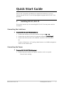
Quick Start Guide
RICi-E3, RICi-T3 should be installed by an experienced technician. If you are
familiar with RICi-E3, RICi-T3, use this quick guide to prepare RICi-E3, RICi-T3 for
operation.
1.
Installing RICi-E3, RICi-T3
This section instructs you on connecting RICi-E3, RICi-T3 to the power and the
network(s).
Connecting the Interfaces
To connect RICi-E3, RICi-T3 to the network:
1. Connect the network to the coax connector designated E3 or T3.
2. Connect the user LAN to the RJ-45 connector designated 10/100 BaseT.
3. Connect the ASCII terminal to the CONTROL connector at the rear panel.
OR
Connect a Telnet host, a PC running a Web browser or an SNMP management
station to the Ethernet port.
Connecting the Power
To connect RICi-E3, RICi-T3 to the power:
•
Connect the power cable to the power connector on the rear panel.
The unit starts running.
RICi-E3, RICi-T3 Ver. 1.0
Installing RICi-E3, RICi-T3
1
Quick Start Guide
Installation and Operation Manual
2.
Configuring RICi-E3, RICi-T3
Configure RICi-E3, RICi-T3 to the desired operation mode via an ASCII terminal
connected to the rear panel CONTROL port. Alternatively, you can manage
RICi-E3, RICi-T3 over Telnet, a PC running a Web browsing application, or SNMP via
the Ethernet or E3 port.
Note
Remote management requires assigning an IP address.
Starting a Terminal Session
To start a terminal session:
1. Connect an ASCII terminal to the CONTROL port at the front panel. The
default settings are as follows:
Baud Rate: 115,200 bps
Data Bits: 8
Parity: None
Stop Bits: 1
Flow Control: None.
2. To optimize the view of the system menus, do the following:
Set the terminal emulator to VT100.
If you are using HyperTerminal, set the terminal mode to the 132-column
mode.
3. Enter your user name and password and proceed with the management
session.
Note
2
The RICi-E3, RICi-T3 default user name is su (lower case). The default password is
1234.
Configuring RICi-E3, RICi-T3
RICi-E3, RICi-T3 Ver. 1.0
RICi-E3, RICi-T3 Installation and Operation Manual
Quick Start Guide
Configuring Basic Parameters
The Quick Setup menu allows you to configure mandatory elements. For
additional information on parameters and the menus, refer to Chapter 4.
To configure RICi-E3, RICi-T3:
1. Navigate to Main > Configuration > Quick Setup.
2. Configure the following parameters:
Host IP Address
Host IP Mask
Default Gateway
Host Tagging (untagged/tagged). If you select Tagged, additional
parameters appear as follows:
Host VLAN ID
Host VLAN Priority
Forwarding Mode (transparent or filter)
VLAN Tag Stacking (enable/disable)
E3/T3 Configuration.
RICi-E3, RICi-T3 Ver. 1.0
Configuring RICi-E3, RICi-T3
3
Quick Start Guide
4
Configuring RICi-E3, RICi-T3
Installation and Operation Manual
RICi-E3, RICi-T3 Ver. 1.0
Contents
Chapter 1. Chapter Name
1.1
1.2
1.3
1.4
Overview....................................................................................................................1-1
Device Options .......................................................................................................1-1
Application .............................................................................................................1-1
Features .................................................................................................................1-3
Physical Description ...................................................................................................1-5
Functional Description................................................................................................1-6
Technical Specifications..............................................................................................1-7
Chapter 2. Installation and Setup
2.1
2.2
2.3
2.4
2.5
2.6
Site Requirements and Prerequisites ..........................................................................2-1
Package Contents ......................................................................................................2-3
Mounting the Unit......................................................................................................2-3
Connecting the Interface Cables .................................................................................2-4
Connecting to the ASCII Terminal................................................................................2-4
Connecting to Power..................................................................................................2-5
Connecting AC Power..............................................................................................2-5
Connecting DC Power..............................................................................................2-5
Chapter 3. Operation
3.1
3.2
3.3
3.4
3.5
3.6
Turning On the Unit ...................................................................................................3-1
Indicators ..................................................................................................................3-1
Default Settings .........................................................................................................3-3
Configuration Alternatives..........................................................................................3-6
Working via ASCII Terminal ......................................................................................3-6
Working with ConfiguRAD .......................................................................................3-9
Working with RADview-Lite ...................................................................................3-11
Menu Map................................................................................................................3-12
Turning Off the Unit.................................................................................................3-13
Chapter 4. Configuration
4.1
4.2
Configuring for Management ......................................................................................4-1
Configuring IP Host Parameters...............................................................................4-2
Entering Device Information....................................................................................4-4
Configuring Communities ........................................................................................4-4
Configuring the Host Encapsulation.........................................................................4-5
Configuring the Network Managers .........................................................................4-6
Controlling the Management Access........................................................................4-8
Configuring Control Port Parameters .......................................................................4-9
Configuring for Operation ........................................................................................4-11
Configuring Interfaces on the Physical Layer..........................................................4-11
Configuring the Bridge ..........................................................................................4-15
Configuring the QoS Priorities ...............................................................................4-18
RICi-E3, RICi-T3 Ver. 1.0
i
Table of Contents
4.3
Installation and Operation Manual
Additional Tasks.......................................................................................................4-19
Displaying the Inventory .......................................................................................4-19
Displaying the Status ............................................................................................4-19
Changing User Name and Password.......................................................................4-23
Transferring Software and Configuration Files .......................................................4-24
Resetting RICi-E3, RICi-T3......................................................................................4-26
Chapter 5. Configuring a Typical Application
5.1
5.2
5.3
5.4
Application Requirements...........................................................................................5-1
Connecting the Cables................................................................................................5-2
Connecting the Ethernet Port..................................................................................5-2
Connecting the E3 or T3 Port ..................................................................................5-2
Connecting the Power.............................................................................................5-2
Configuring the RICi-E3, RICi-T3 System Parameters....................................................5-3
Configuring Parameters via ASCII Terminal ...............................................................5-3
Configuring the Physical Ports ....................................................................................5-4
Configuring the E3 Port...........................................................................................5-4
Configuring the T3 Port...........................................................................................5-4
Configuring the Ethernet Port .................................................................................5-5
Configuring the Bridge Parameters ..........................................................................5-5
Building the MAC Table............................................................................................5-5
Configuring the Bridge Port .....................................................................................5-6
Configuring the QoS Priorities .................................................................................5-6
Chapter 6. Diagnostics and Troubleshooting
6.1
6.2
6.3
6.4
6.5
6.6
Monitoring Performance.............................................................................................6-1
Interface Statistics..................................................................................................6-1
Displaying System Messages ...................................................................................6-4
Handling Alarms .........................................................................................................6-5
Viewing Alarms .......................................................................................................6-5
Clearing Log File......................................................................................................6-5
Troubleshooting.........................................................................................................6-6
Connectivity Tests......................................................................................................6-6
Running Ping Test ...................................................................................................6-6
Tracing the Route ...................................................................................................6-7
Loopback Test ........................................................................................................6-8
Testing the Cables......................................................................................................6-9
Technical Support ....................................................................................................6-10
Appendix A. Pinouts
Appendix B. Boot Manager
ii
RICi-E3, RICi-T3 Ver. 1.0
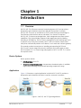
Chapter 1
Introduction
1.1
Overview
RICi-E3, RICi-T3 is Ethernet customer-located equipment (CLE) and provides a
demarcation point between the private LAN and the operator’s network.
RICi-E3, RICi-T3 serves as an Ethernet to E3/T3 media converter that bridges a
Fast Ethernet LAN interface and an unframed E3 or framed T3 interface.
RICi-E3, RICi-T3 features autonegotiation, fault management and flow control
capabilities. The internal bridge supports VLAN tagging and priority labeling
according to IEEE 802.1p. The unit can be managed via a local terminal port (outof band) or any of the ports (inband). RICi-E3, RICi-T3 includes a DHCP client
utility that automatically obtains an IP address, an IP mask and a default gateway.
This manual provides instructions on installing and operating RICi-E3 and
RICi-T3 units. Screen images illustrate the workflow and usually apply to both
RICi-E3 and RICi-T3. If a screen image only applies to RICi-E3 or RICi-T3, it carries
the respective title.
Device Options
Device options include:
•
Interface types: E3 or T3
•
Temperature-hardened option: A temperature-hardened option is available,
significantly extending the permitted operating temperature range.
Application
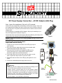
Figure 1-1 illustrates a typical application in which RICi-E3, RICi-T3 provides a
demarcation point between the carrier’s and the customer’s networks.
Figure 1-1.RICi-E3, RICi-T3 Typical Application
RICi-E3, RICi-T3 Ver. 1.0
Overview
1-1
Chapter 1 Introduction
Installation and Operation Manual
Features
RICi-E3, RICi-T3 offers the features specified below.
Network Interface
The network interface terminates in an E3 or T3 coax network port.
User Interface
The user interface terminates in a 10/100BaseT port, operating in half or full
duplex mode. The 10/100BaseT user port supports auto negotiation.
Fault Management
The unit provides a fault propagation mechanism. In cases of error conditions on
the TDM port, a fault propagation feature tears down the link integrity on the
Fast Ethernet port. This indicates the error conditions to the Ethernet network,
enabling connected routers to reroute the traffic if required.
Internal Bridge
The internal bridge of the unit operates in two modes:
•
Transparent – no learning is performed, each received packet is forwarded to
the other port. Filtering is performed on static MAC address entries.
•
Filter – learning and filtering are enabled.
Management
Setup, monitoring and tests can be performed using one of the following
methods:
•
•
Out-of band management – via an ASCII terminal connected to the V.24/RS232 DTE control port.
Inband management – via the Ethernet port, using Telnet, ConfiguRAD, or
RADview-Lite (SNMP). RICi-E3, RICi-T3 allows up to five concurrent
management sessions in addition to an ASCII terminal session.
ConfiguRAD
ConfiguRAD is a user-friendly Web-based terminal management system enabling
remote device configuration and maintenance. It is embedded in the unit and
provided at no extra cost. ConfiguRAD can be run from any standard Web
browser.
RADview-Lite
RADview-Lite is a user-friendly and powerful SNMP-based element management
application, used for planning, provisioning and managing heterogeneous
networks. RADview-Lite provides monitoring capabilities for RAD products and
networks via their SNMP agents. Configuration and diagnostic capabilities are
available via a GUI-cut-through to ConfiguRAD.
1-2
Overview
RICi-E3, RICi-T3 Ver. 1.0
RICi-E3, RICi-T3 Installation and Operation Manual
Chapter 1 Introduction
Inband Management
For inband management, the IP host of RICi-E3, RICi-T3 can be configured to
operate in tagged or untagged mode:
•
When tagging is enabled, the IP host packets receive a VLAN tag, creating a
dedicated management VLAN.
DHCP Client
When the unit is starting up and if the DHCP client is enabled, the DHCP server
automatically assigns an IP address, an IP mask and a default gateway to the unit.
Diagnostic Tools
A built-in ping utility allows checking IP connectivity by pinging remote IP hosts.
The Trace Route application can quickly trace a route from RICi-E3, RICi-T3 to any
other network device.
1.2
Physical Description
Figure 1-2 illustrates a RICi-E3 and a RICi-T3 unit.
Figure 1-2. RICi-E3, RICi-T3, 3D View
LEDs on the front panel display the status of power, Ethernet links, E3/T3 links
and alarms. For a detailed description of the front panel, refer to Chapter 3.
The rear panel is equipped with an AC power connector for AC and DC power
supply, a V.24 terminal connector, network and user Ethernet ports. For a
detailed description of the rear panel, refer to Chapter 2.
RICi-E3, RICi-T3 Ver. 1.0
Physical Description
1-3
Chapter 1 Introduction
Installation and Operation Manual
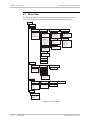
1.3
Functional Description
This section provides a functional description of RICi-E3, RICi-T3 by means of a
block diagram (Figure 1-3).
Network Interface
Ethernet
Interface
E3/T3
Framer
CPU
ETH
Switch
RS-232
Figure 1-3. Block Diagram of RICi-E3, RICi-T3
The RICi-E3, RICi-T3 media converter consists of the following major modules:
•
•
•
•
•
•
•
1-4
Power supply – provides +5V, +3.3V voltage to the internal elements.
E3/T3 framer – formats data for transmission and extracts data for reception
at T3 and E3 line speeds.
CPU – controls the RICi-E3, RICi-T3 operation.
Ethernet switch – forwards packets between the Ethernet ports and the CPU.
User Ethernet interface – connects RICi-E3, RICi-T3 to the user LAN.
Network E3/T3 interface – connects RICi-E3, RICi-T3 to the E3/T3 network.
RS-232 port – communicates with the ASCII terminal.
Functional Description
RICi-E3, RICi-T3 Ver. 1.0
RICi-E3, RICi-T3 Installation and Operation Manual
1.4
Chapter 1 Introduction
Technical Specifications
Network Interface
E3
Interface type,
connector
Coax BNC
Compliance
G.703
Framing
Unframed
Data Rate
34.368 Mbps
Line Code
HDB3
Impedance
75Ω, unbalanced
Interface type,
connector
Coax BNC
Compliance
GR-499-CORE
ANSI T1.107
ANSI T1.102
Framing
C-bit parity, M23
Data Rate
44.736 Mbps
Line Code
B3ZS
Impedance
75Ω, unbalanced
Type
10/100BaseT
Interface type,
connector
Electrical, RJ-45
Operation Mode
Full or half duplex, autonegotiation, flow control
Compliance
IEEE 802.3, 802.3u
Internal Bridge
Forwarding Mode
Transparent or filter
Management
Out-of-Band
Via dedicated terminal port; V.24/RS-232 DCE;
9.6, 19.2, 115.2 kbps; DB-9 female connector
Inband
Via either the Ethernet or E3/T3 port
T3
User Interface
RICi-E3, RICi-T3 Ver. 1.0
Technical Specifications
1-5
Chapter 1 Introduction
Front Panel
Indicators
Installation and Operation Manual
PWR (green)
On – RICi-E3, RICi-T3 is on
Off – RICi-E3, RICi-T3 is off
TST (yellow)
On – test is in progress
Off – no test is in progress
Blinking (red/yellow) – alarm detected while test in progress
ALM (red)
On – alarm has been detected
Off – no alarm has been detected
Blinking (red/yellow) – alarm detected while test in progress
LOS (red)
On – network LOS (Loss of Signal) detected
Off – network signal uninterrupted
LOS (yellow)
RICi-T3 only
On – Yellow alarm (RAI) has been detected
Off – no Yellow alarm has been detected
ETH LINK (green)
Ethernet Link Integrity:
On – link is connected
Off – link is disconnected
Rear Panel
Indicators
LINK (green)
Ethernet Link Integrity:
On – link is connected
Off – link is disconnected
ACT (yellow)
Ethernet Activity:
Blinking – Frames are being received or sent
Off – No frames are being received or sent
Power
Physical
Environment
1-6
AC /DC Source
100 to 240 VAC or 48/60 VDC (40 to 72 VDC)
Consumption
8W
Height
43.7 mm (1.7 in)
Width
220 mm (8.6 in)
Depth
170 mm (6.7 in)
Weight
0.5 kg (1.1 lb)
Temperature
RICi-E3, RICi-T3: 0 to 50°C (32 to 122°F)
RICi-E3/H RICi-T3/H: -22° to 70°C (-7.6° to 158°F)
Humidity
Up to 90%, non-condensing
Technical Specifications
RICi-E3, RICi-T3 Ver. 1.0
Chapter 2
Installation and Setup
This chapter describes installation and setup procedures for the RICi-E3, RICi-T3
unit.
After installing the unit, refer to Chapter 3 for the operating instructions.
If a problem is encountered, refer to Chapter 6 for test and diagnostic
instructions.
Internal settings, adjustment, maintenance, and repairs may be performed only
by a skilled technician who is aware of the hazards involved.
Warning
Grounding
Always observe standard safety precautions during installation, operation, and
maintenance of this product.
For your protection and to prevent possible damage to equipment when a fault
condition, e.g., a lightning stroke or contact with high-voltage power lines, occurs
on the cables connected to the equipment, RICi-E3, RICi-T3 must be properly
grounded at any time. Any interruption of the protective (grounding) connection
inside or outside the equipment, or the disconnection of the protective ground
terminal can make this equipment dangerous. Intentional interruption is
prohibited.
2.1
Site Requirements and Prerequisites
AC-powered RICi-E3, RICi-T3 units should be installed within 1.5m (5 ft) of an
easily-accessible grounded AC outlet capable of furnishing the voltage in
accordance with RICi-E3, RICi-T3 nominal supply voltage.
DC-powered RICi-E3, RICi-T3 units require a -48 VDC power source, which must be
adequately isolated from the main supply.
Note
Refer also to the sections describing connections of AC and DC mains at the
beginning of the manual.
Allow at least 90 cm (36 in) of frontal clearance for operating and maintenance
accessibility. Allow at least 10 cm (4 in) clearance at the rear of the unit for signal
lines and interface cables.
The ambient operating temperature of RICi-E3, RICi-T3 is 0 to 50°C (32 to 122°F),
at a relative humidity of up to 90%, non-condensing. If you ordered the
temperature-hardened version, the ambient operating temperature is
-22° to 70°C (-7.6° to 158°F).
RICi-E3, RICi-T3 Ver. 1.0
Site Requirements and Prerequisites
2-1
Chapter 2 Installation and Setup
2.2
Installation and Operation Manual
Package Contents
The RICi-E3, RICi-T3 package includes the following items:
•
One RICi-E3 or RICi-T3 unit
•
CBL-DB9F-DB9M-STR control port cable (if ordered)
•
AC power cord
•
DC adapter
•
RM-33-2 rack mount kit (if ordered)
2.3
Mounting the Unit
RICi-E3, RICi-T3 is designed for installation as a desktop unit. You may also mount
two units into a 19” rack or attach one unit to a wall.
•
For rack mounting instructions, refer to the RM-33-2 installation kit manual.
•
For wall mounting instructions, see the drilling template at the end of this
manual.
•
If RICi-E3, RICi-T3 is to be used as a desktop unit, place and secure the unit
on a stable, non-movable surface.
Refer to the clearance and temperature requirements in Site Requirements and
Prerequisites.
2-2
Mounting the Unit
RICi-E3, RICi-T3 Ver. 1.0
Installation and Operation Manual
2.4
Chapter 2 Installation and Setup
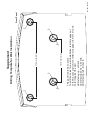
Connecting the Interface Cables
Figure 2-1 illustrates the rear panel of a typical RICi-T3 unit. The RICi-E3 unit is
xsimilar, except for an E3 interface instead of the T3 interface. Appendix A
specifies the RICi-E3, RICi-T3 connector pinouts.
~100-240VAC/
48/60VDC
10/100BaseT
LINK
T3
RX
CONTROL
TX
ACT
Figure 2-1. RICi-T3 Rear Panel
To connect the Ethernet interface:
•
Connect the user LAN to the RJ-45 connector designated 10/100 BaseT.
To connect the E3 or T3 interface:
1. Connect the Rx cable to the BNC connector designated Rx.
2. Connect the Tx cable to the BNC connector designated Tx.
2.5
Connecting to the ASCII Terminal
You may connect RICi-E3, RICi-T3 to an ASCII terminal using the 9-pin D-type
female CONTROL connector at the rear panel. Refer to Appendix A for the
connector pinout.
To connect the ASCII terminal to the CONTROL port:
1. Connect the male 9-pin D-type connector of the CBL-DB9F-DB9M-STR Control
Port cable to the connector labeled CONTROL.
2. Connect the other end of this cable to an ASCII terminal.
RICi-E3, RICi-T3 Ver. 1.0
Connecting to the ASCII Terminal
2-3
Chapter 2 Installation and Setup
2.6
Installation and Operation Manual
Connecting to Power
RICi-E3, RICi-T3 accepts either 110-240 VAC or -48/-60 VDC power through the
same power inlet.
Warning
Before connecting or disconnecting any communication cable, the unit must be
earthed by connecting its power cord to a power outlet with an earth terminal,
and by connecting the earth terminal on the panel (if provided) to a protective
ground.
Interrupting the protective (ground) conductor inside or outside the unit, or
disconnecting the protective ground terminal may render this unit dangerous.
Intentional interruption is prohibited.
Connecting AC Power
AC power is supplied to the RICi-E3, RICi-T3 modem through a standard 3-prong
socket, illustrated in Figure 2-1.
AC power should be supplied via a 1.5m (5 ft) standard power cable terminated
by a standard 3-prong socket. A cable is provided with the unit.
To connect AC power:
1. Connect the power cable to the power connector on the RICi-E3, RICi-T3 rear
panel.
2. Connect the power cable to the mains.
The unit automatically turns on once it has been connected.
Connecting DC Power
A special IEC 60320 adapter for 48/60 VDC power is available for
RICi-E3, RICi-T3.
To connect DC power:
•
2-4
Refer to the DC power supply connection supplement for instructions on
wiring the DC adapter, and to the Handling Energized Products section.
Connecting to Power
RICi-E3, RICi-T3 Ver. 1.0
Chapter 3
Operation
This chapter:
•
Explains how to power RICi-E3, RICi-T3 on and off
•
Provides a detailed description of the front panel controls and indicators and
their functions
•
Defines the default settings
•
Provides the configuration alternatives
•
Illustrates the management menus.
For additional information on parameters and menus, refer to Chapter 4.
3.1
Turning On the Unit
To turn on the unit:
•
Connect the power cord to the mains.
The PWR indicator lights up and remains lit as long as RICi-E3, RICi-T3
receives power.
Once installed, RICi-E3, RICi-T3 does not require further attention with the
exception of occasional monitoring of front panel indicators. RICi-E3, RICi-T3 only
requires configuring the unit to comply with its operational requirements, or for
testing.
3.2
Indicators
The unit's LEDs are located at the front panel as illustrated in Figure 3-1.
Table 3-1 lists the functions of the RICi-E3, RICi-T3 LED indicators.
RICi-T3
Figure 3-1. RICi-T3 Front Panel
RICi-E3, RICi-T3 Ver. 1.0
Indicators
3-1
Chapter 3 Operation
Installation and Operation Manual
Table 3-1. RICi-E3, RICi-T3 LEDs and Controls
Name
Color
Function
PWR
Green
On – power connected
Off – power disconnected
TST
Yellow
On – test in progress
Off – no test in progress
Blinking (red/yellow) – test in progress and alarm detected
ALM
Red
On – alarm detected
Off – no alarm
Blinking (red/yellow) – test in progress and alarm detected
LOS
Red
On – loss of signal detected, any T3 alarm except RAI
Off – network signal detected
Yellow
On – RAI alarm detected
Applies to T3 units only
ETH LINK
Green
On – link connected
Off – link disconnected
3-2
Indicators
RICi-E3, RICi-T3 Ver. 1.0
Installation and Operation Manual
3.3
Chapter 3 Operation
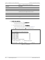
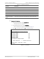
Default Settings
Table 3-2 lists the default settings of the RICi-E3, RICi-T3 configuration
parameters.
Table 3-2. Default Settings
Type
Parameter
Default Value
IP address
0.0.0.0
IP mask
255.255.255.0
Default gateway
0.0.0.0
Default IP
0.0.0.0
DHCP
Disable
Read community
Public
Write community
Private
Trap community
Public
Name
RICi-E3, RICi-T3
Description
E3/T3 Intelligent Ethernet
Converter
Location
The Location of the Device
Contact Person
Name of Contact Person
Telnet
Enable
SNMP access
Enable
Web access
Enable
User name for superuser
su (full control)
User name for guest user
user (read-only)
Host Tagging
Untagged
Host VLAN ID
1
Host VLAN Priority
0
Alarm ID
1
Trap Status
Active
Baud Rate
115200 bps
Set Scrolling Window Size
4
Security Timeout
10
System
Host
Device Info
Management Access
User Access
Encapsulation
Alarm Trap Mask
Control Port
RICi-E3, RICi-T3 Ver. 1.0
Default Settings
3-3
Chapter 3 Operation
Type
Installation and Operation Manual
Parameter
Default Value
Administrative Status
Up
Flow Control
Enable
Autonegotiation
Enable
Max Capability Advertised
100base – TX Full Duplex
MDIX Auto Cross Over
Enable
Administrative Status
Up
Clock
LBT
Protocol
HDLC
Administrative Status
Up
Framing
M23
Tx Clock
LBT
Line Build Out
Up to 255 ft
Protocol
HDLC
Forwarding Mode
Transparent
Aging Time
300
VLAN Tag Stacking
Disable
Port VID/Stacking VID
2
Copy Origin Priority
Disable
Default Priority
0
User Priority 1-7
Traffic Class 0
Rate Limitation
No Limit
Burst Size
96
Limit Packet Type
All
Rate Limitation
No Limit
Physical Ports
Ethernet User
E3
T3
Bridge
Bridge Port
QoS
Rate Limitation
Ingress
Egress
3-4
Default Settings
RICi-E3, RICi-T3 Ver. 1.0
Installation and Operation Manual
Type
Chapter 3 Operation
Parameter
Default Value
Destination IP Address
0.0.0.0
Number of Frames to Send
1
MAC Swap
Disable
Looped Data
All
VLAN ID
1
Direction
Local
Forced Source Mac
00-00-00-00-00-00
Forced Destination Mac
00-00-00-00-00-00
Loopback Timeout
0
Loopback State
Disable
Port
Network 1
VLAN ID
1
State
Off
Diagnostics
Ping
Loopbacks
VLAN Test
RICi-E3, RICi-T3 Ver. 1.0
Configuration Alternatives
3-5
Chapter 3 Operation
Installation and Operation Manual
3.4
Configuration Alternatives
Configuration and monitoring operations are performed locally from an ASCII
terminal connected to the control port or from a PC on the network via
ConfiguRAD or RADview-Lite.
The following functions are supported by the RICi-E3, RICi-T3 management
software:
•
Viewing system information
•
Modifying configuration and mode of operation, including setting system
default values and resetting the unit
•
Monitoring RICi-E3, RICi-T3 performance
•
Initiating connectivity tests
•
Upgrading software.
Working via ASCII Terminal
RICi-E3, RICi-T3 includes a V.24/RS-232 asynchronous DCE port, designated
CONTROL and terminated in a 9-pin D-type female connector. The CONTROL port
continuously monitors the incoming data stream and immediately responds to
any input string received through this port.
You may configure the RICi-E3, RICi-T3 control port to communicate at 9.6, 19.2,
or 115.2 Kbps. To communicate with a PC, you have to set it to communicate at
115. 2 Kbps.
To start a terminal control session:
1. Make sure all RICi-E3, RICi-T3 cables and connectors are properly connected.
2. Connect RICi-E3, RICi-T3 to a PC equipped with an ASCII terminal emulation
application such as HyperTerminal or Procomm.
3. Connect an ASCII terminal to the CONTROL port at the front panel. The
default settings are as follows:
Baud Rate: 115,200 bps
Data Bits: 8
Parity: None
Stop Bits: 1
Flow Control: None.
3-6
Configuration Alternatives
RICi-E3, RICi-T3 Ver. 1.0
Installation and Operation Manual
Chapter 3 Operation
4. To optimize the view of the system menus, do the following:
Set the terminal emulator to VT100.
If you are using HyperTerminal, set the terminal mode to the 132-column
mode.
5. Power up RICi-E3, RICi-T3.
When the unit has initialized and completed the self-test, a menu
appears displaying initialization and self-test results.
Logging In
To log in:
1. Enter the default user name su for superuser.
2. Enter the default password 1234.
Note
• It is recommended to change default passwords to prevent unauthorized
access to the unit.
• If you do not enter at least one character within 5 minutes, you will have to
log in again.
Selecting Options
To select an option:
1. Type the number corresponding to the option and press <Enter>.
2. If you performed a change, Save appears as the last option in the menu.
3. Type the number corresponding to the Save option in the current menu, and
press <Enter> to save your change.
RICi-E3, RICi-T3 updates its database with the new value or displays a
new menu for the selected option.
4. If you press <ESC> to exit the menu without saving your changes, the
following message appears:
“Do you want to save changes (Y/N/C)?”
Type the appropriate letter, Yes, No, or Cancel.
Note
When a menu option has only two values, typing the option number and pressing
<Enter> will toggle between the available values.
RICi-E3, RICi-T3 Ver. 1.0
Configuration Alternatives
3-7
Chapter 3 Operation
Installation and Operation Manual
Navigating Tables
Some RICi-E3, RICi-T3 management screens, such as the Inventory table and
Manager table exceed the screen height and/or width and require scrolling to
navigate between parameters.
To navigate a table, use the keys listed below:
Note
•
<Ctrl>+L – scroll left, Left Arrow – move left,
•
<Ctrl>+R – scroll right, Right Arrow – move right
•
Up Arrow – move up
•
Down Arrow – move down
•
<Tab> – select next changeable cell
•
G<row number>, <col number> - navigate to the specified cell.
• You can display these navigation keys by pressing <?> from a table.
• The navigation keys are case sensitive.
3-8
Configuration Alternatives
RICi-E3, RICi-T3 Ver. 1.0
Installation and Operation Manual
Chapter 3 Operation
Working with ConfiguRAD
ConfiguRAD is a Web-based remote access terminal management software. It
provides a user-friendly interface for configuring, collecting statistics and
performing tests.
Requirements for Web Based Management
•
Internet Explorer 6.0 and up, running on Windows™
•
Netscape Communicator 7.0 and up, running on Windows™, HPOV or Linux
•
Firefox 1.0.4 and up, running on Windows™
•
Mozilla 1.4.3 and up, running on Linux.
Before you start using a Web browser for remote management or monitoring:
•
Enable scripts.
•
Configure the firewall that might be installed on your PC to allow access to
the destination IP address.
•
Disable pop-up blocking software, such as Google Popup Blocker. You may
also have to configure spyware and adware protecting software to accept
traffic from/to the destination IP address.
•
To prevent configuration errors, you must flush the browser’s cache
whenever you return to the same screen.
RICi-E3, RICi-T3 Ver. 1.0
Configuration Alternatives
3-9
Chapter 3 Operation
Installation and Operation Manual
Logging In
To log in from a Web browser:
1. Connect the Ethernet port to the LAN.
2. Verify that an IP address has been assigned to the relevant unit, using an
ASCII terminal.
3. Open the Web browser.
4. Disable any pop-up blocking software, such as Google Popup Blocker.
5. In the address field, enter the IP address of RICi-E3, RICi-T3 and then press
<Enter>. The address line reads something like http://172.16.100.253.
The Opening window appears.
6. Click LOGIN; you are asked for the user name and the password.
7. Enter your user name and the password. The default user name for
read/write permission is su and the default password is 1234.
The ConfiguRAD Main menu appears.
Notes
• It is recommended to change default passwords to prevent unauthorized
access to the unit.
• RICi-E3, RICi-T3 allows two management sessions to be active simultaneously:
one network session (Telnet, ConfiguRAD, RADview-Lite) and one ASCII
terminal session.
• If no user input is detected for 5 minutes during a ConfiguRAD session,
RICi-E3, RICi-T3 automatically disconnects from the management station.
Navigating the ConfiguRAD Menus
ConfiguRAD is a Web-based remote access terminal management software. It
provides a user-friendly interface for configuring, collecting statistics and
performing diagnostic tests on the RICi-E3, RICi-T3 units. Menus and available
options are identical to the ones available using Telnet or an ASCII terminal.
At the left-hand bottom corner, ConfiguRAD are the auxiliary management tools:
•
Status. Shows the number of users currently managing RICi-E3, RICi-T3
•
Trace. Opens an additional pane for system messages, progress indicators
such as ping, software and configuration file downloads, and alarms. It is
recommended to keep the trace pane open all the time.
•
Refresh All. Refreshes performance registers.
To choose an option:
1. Click a link in the ConfiguRAD screen to display the next menu.
2. Once the target screen appears, select a value from the drop-down list or
enter it in into a text field.
3-10
Configuration Alternatives
RICi-E3, RICi-T3 Ver. 1.0
Installation and Operation Manual
Chapter 3 Operation
Working with RADview-Lite
RADview-Lite is a user-friendly and powerful SNMP-based element management
system (EMS), used for planning, provisioning and managing heterogeneous
networks. RADview-Lite provides monitoring capabilities for RAD products and
networks using their built-in SNMP agents.
Configuration and diagnostic capabilities are available via a GUI-cut-through to
ConfiguRAD.
For additional information on RADview-Lite, contact your local distributor.
RICi-E3, RICi-T3 Ver. 1.0
Configuration Alternatives
3-11
Chapter 3 Operation
3.5
Installation and Operation Manual
Menu Map
Use the menu map as a reference while monitoring and configuring your unit.
Chapter 4 illustrates the menus and explains the associated parameters.
Main menu
1. Inventory
2. Configuration
1. Quick Setup
1. Host IP Address
2. Host IP Mask
3. Default Gateway
4. Host Tagging
5. Forwarding Mode
6. VLAN Tag Stacking
7. T3 Configuration
2. System
1. Management
1. Device Info
1. Device Name
2. Location
3. Contact Person
3. Physical Ports
4. Applications
1. Ethernet
1. Bridge
1. Administrative Status
2. Auto-negotiation
3. Flow Control
4. Max Capability Advertised
5. MDiX Auto Cross Over
2. Host IP
1. IP Address
2. IP Mask
3. Default Gateway
4. Read Community
5. Write Community
6. Trap Community
7. Host Tagging
2. T3
2. QoS
1. Administrative Status
2. Framing
3. Tx Clock
4. Line Build Out
5. Protocol
2. E3
3. Manager List
1. Administrative Status
2. Tx Clock
3. Protocol
4. Management Access
1. User Access
2. Telnet Access
3. SNMP Access
4. Web Access
1. Forwarding Mode
2. Aging Time
3. Static MAC Table
4. Bridge Port
1. User Priority 0 >
2. User Priority 1 >
3. User Priority 2 >
4. User Priority 3 >
5. User Priority 4 >
6. User Priority 5 >
7. User Priority 6 >
8. User Priority 7 >
2. Control Port
1. Baud Rate
2. Scrolling Window
3. Security Timeout
3. Fault Propagation
4. DHCP Client
5. Set Factory Defaults
6. Reset Device
3. Monitoring
1. System
MAC address
System Up Time
1. Connection Status
2. Log File
2. Physical Ports
3. Applications
1. MAC Table
1. Ethernet Status
2. Ethernet Statistics
3. E3, T3 Status
4. E3, T3 Statistics
5. E3, T3 PM
1. Current Statistics
2. Interval Statistics
3. Total Interval Statistics
4. Clear Statistics
4. Diagnostics
1. Ping
1. Destination IP Address
2. Number of Frames
to Send
3. Send Ping
4. Stop Ping
2. Trace Route
1. Destination IP Address
2. Display Trace Route
3. Stop Trace Route
3. Loopback
4. VCT Test
1. E3, T3 Loopback
2. Loopback timeout
5. Utilities
1. File Transfer
1. Server IP Address
2. Remote Filename
3. File Type
4. Command
Figure 3-2. Menu Map
3-12
Menu Map
RICi-E3, RICi-T3 Ver. 1.0
Installation and Operation Manual
3.6
Chapter 3 Operation
Turning Off the Unit
To power off the unit:
•
RICi-E3, RICi-T3 Ver. 1.0
Remove the power cord from the power source.
Turning Off the Unit
3-13
Chapter 3 Operation
3-14
Turning Off the Unit
Installation and Operation Manual
RICi-E3, RICi-T3 Ver. 1.0
Chapter 4
Configuration
This chapter illustrates the RICi-E3, RICi-T3 configuration screens and explains
their parameters.
For quick reference, a menu tree of the RICi-E3, RICi-T3 management software is
available in Chapter 3.
The remaining sections in this chapter explain the parameters available via the
respective options in the Main menu.
For convenience, parameters that are mandatory for configuration, such as IP
parameters of the RICi-E3, RICi-T3 host or forwarding mode, are provided in the
Quick Setup menu (Main menu > Configuration > Quick Setup). For information
on this menu, refer to the Quick Start Guide at the beginning of this manual. For
additional information on the associate parameters, refer to the relevant sections
in the configuration chapter.
Note
Menus are illustrated for both RICi-E3 and RICi-T3. The menus are the same
unless specified otherwise
4.1
Configuring for Management
For first use, you have to configure management parameters via an ASCII terminal
connected to the CONTROL port. Once the host IP parameters are set, you may
access RICi-E3, RICi-T3 via ConfiguRAD or RADview to continue configuring for
operation. To configure RICi-E3, RICi-T3 for management, do the following:
•
Configuring IP Host Parameters
•
Entering Device Information
•
Configuring Communities
•
Configuring the Host Encapsulation
•
Configuring the Network Managers
•
Controlling the Management Access
RICi-E3, RICi-T3 Ver. 1.0
Configuring for Management
4-1
Chapter 4 Configuration
Installation and Operation Manual
Configuring IP Host Parameters
You may manage RICi-E3, RICi-T3 using a network management station on the
LAN that is connected to RICi-E3, RICi-T3. In order to establish a proper
connection, you have to configure the host IP address, the subnet mask and the
default gateway. It is also possible to automatically receive these host IP
parameters via the DHCP client when starting the unit.
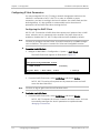
Configuring the DHCP Client
RICi-E3, RICi-T3 maintains a DHCP client that requests an IP address from a DHCP
server, when the unit is connected to the network. The DHCP client can be
enabled or disabled. RICi-E3, RICi-T3 ships with the DHCP disabled by default.
Note
You have to configure the DHCP client via an ASCII terminal or an SNMP manager
such as RADview. This option is masked for Telnet and ConfiguRAD sessions.
To enable the DHCP client:
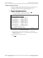
1. Navigate to Main Menu > Configuration > System > DHCP Client.
The DHCP Client menu appears as illustrated in Figure 4-1.
RICi-E3, RICi-T3
Configuration>System>DHCP Client
1. DHCP Client
(Disable)
>
ESC-prev menu; !-main menu; &-exit
1 user(s)
Figure 4-1. DHCP Client Menu
2. From the DHCP Client menu, select DHCP Client and choose Enable.
RICi-E3, RICi-T3 receives all required host IP parameters once the DHCP
server has been identified.
Note
You have to log on again once the unit has been reset.
To disable the DHCP client:
•
From the DHCP Client menu, select DHCP Client and choose Disable.
RICi-E3, RICi-T3 releases the current IP address and then resets. You have
to manually reconfigure the host IP parameters as explained under
Managing IP Parameters.
4-2
Configuring for Management
RICi-E3, RICi-T3 Ver. 1.0
Installation and Operation Manual
Chapter 4 Configuration
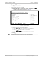
Managing IP Parameters
To define host IP parameters manually:
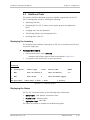
1. Navigate to Main Menu > Configuration > System > Management > Host IP.
The Host IP menu appears as illustrated in Figure 4-2.
RICi-E3, RICi-T3
Configuration>System> Management >Host IP
1.
2.
3.
4.
5.
6.
7.
IP Address
IP Mask
Default gateway
Read community
Write community
Trap community
Host Tagging
...
...
...
...
...
...
...
(0.0.0.0)
(255.255.255.0)
(0.0.0.0)
(public)
(private)
(public)
(untagged)
>
ESC-prev menu; !-main menu; &-exit;
1 user(s)
Figure 4-2. Host IP Menu
2. From the Host IP menu, perform the following:
Select Host IP List to define the IP address of the SNMP host.
Select IP Mask to define the host IP subnet mask.
Select Default Gateway to set the default gateway IP address.
3. Select Save.
Note
The default gateway must belong to the same subnet as the host.
RICi-E3, RICi-T3 Ver. 1.0
Configuring for Management
4-3
Chapter 4 Configuration
Installation and Operation Manual
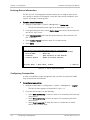
Entering Device Information
The RICi-E3, RICi-T3 management software allows you to assign a name to the
unit, specify its location to distinguish it from the other devices installed in your
system, and assign a contact person.
To enter device information:
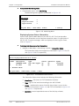
1. Navigate to Main Menu > System >Management > Device Info.
The Device Information menu appears as illustrated in Figure 4-3.
2. From the Device Info menu, select Device Name and enter a desired name for
the RICi-E3, RICi-T3 unit.
3. Select Device Location and enter the desired name for the current RICi-E3,
RICi-T3 location.
4. Select Contact Person and enter name of a contact person.
5. Select Save.
RICi-T3
Configuration>System>Management>Device Information
Description
(T3 Intelligent Ethernet Converter)
1. Device Name
... (RICi-T3)
2. Location
... (The Location of the Device)
3. Contact Person ... (Name of Contact Person)
>
ESC-prev menu; !-main menu; &-exit;
1 user(s)
Figure 4-3. Device Information Menu
Configuring Communities
In order to establish a proper management link, you have to specify the SNMP
trap, read and write communities.
To configure communities:
1. Navigate to Main Menu > Configuration > System > Management > Host IP.
The Host IP menu appears as illustrated in Figure 4-2.
2. From the Host IP menu, do the following:
Select Read Community to enter the name of a community with read-only
authorization.
Select Write Community to enter the name of a community with write
authorization.
Select Trap Community to enter the name of a community to which
RICi-E3, RICi-T3 sends traps.
4-4
Configuring for Management
RICi-E3, RICi-T3 Ver. 1.0
Installation and Operation Manual
Chapter 4 Configuration
Configuring the Host Encapsulation
The RICi-E3, RICi-T3 management software allows you to separate traffic. You can
choose to allow packets to be received by the network port, the user port, by
both or none of them. To separate traffic, you have to tag the VLAN packets and
specify the VLAN ID, the priority and ports to be open to the relevant packets.
To configure the host encapsulation:
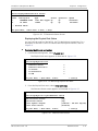
1. Navigate to Main Menu > Configuration > System > Management > Host IP.
The Host IP menu appears as illustrated in Figure 4-2.
2. Select Host Tagging to enable or disable VLAN tagging performed by the host
as follows:
Untagged. The IP host operates like a regular bridge with the network and
user interfaces acting as bridge ports. Any packet, including VLAN-tagged,
can be forwarded to the user Ethernet port.
Tagged. When the IP host packets are sent with a VLAN tag, they are
forwarded to and received via the device ports, creating a dedicated
management VLAN. All packets with the management VLAN tag received
at the user Ethernet port are discarded.
If you select Tagged, three additional parameters appear as illustrated in
Figure 4-4:
VLAN ID. Specify a value between 1 and 4094.
VLAN Priority. Specify the priority level for the host VLAN (0–7).
Physical Ports Access. Specify which port(s) can receive the IP host
packets. The following options are possible:
All
Network Port Only
User Port Only
None
3. Select Save.
RICi-E3, RICi-T3 Ver. 1.0
Configuring for Management
4-5
Chapter 4 Configuration
Installation and Operation Manual
RICi-E3, RICi-T3
Configuration>System> Management >Host IP
1. IP Address
2. IP Mask
3. Default gateway
4. Read community
5. Write community
6. Trap community
7. Host Tagging
8. Host VLAN ID [1-4094]
9. Host VLAN priority [0-7]
10. Physical Ports Access
... (0.0.0.0)
... (255.255.255.0)
... (0.0.0.0)
... (public)
... (private)
... (public)
... (Tagged)
... (1)
... (0)
... (Network port only)
>
ESC-prev menu; !-main menu; &-exit;
1 user(s)
Figure 4-4. Host IP Menu (Host Tagging selected)
Configuring the Network Managers
Define or modify the network managers to which the SNMP agent of RICi-E3,
RICi-T3 sends traps. Up to ten network managers can be defined. Entering the IP
address and corresponding subnet mask defines each manager. In addition, you
can temporarily prevent a network manager from receiving traps by masking the
network manager. Before editing the manager list, it is necessary to add at least
one network manager.
To add a network manager:
1. From the Management menu, select Manager List.
The Manager List menu appears as illustrated in Figure 4-5.
RICi-E3, RICi-T3
Configuration>System>Management>Manager List
Manager ID
Manager IP
Manager IP Mask
1.
1.1.1.1
255.255.255.0
2.
2.2.2.2
255.255.255.0
3.
3.3.3.3
255.255.255.0
4.
4.4.4.4
255.255.255.0
Manager Trap Mask
Disable
Disable
Disable
Disable
1. Change cell
....(1.1.1.1)
>
x – Clear Table
ESC-prev menu; !-main menu; &-exit; ?-help
1 user(s)
Figure 4-5. Manager List Menu
2. In the Manager List menu, press <A> to add a manager.
The Manager List menu switches to the Add mode as illustrated in
Figure 4-6.
4-6
Configuring for Management
RICi-E3, RICi-T3 Ver. 1.0
Installation and Operation Manual
Chapter 4 Configuration
RICi-E3, RICi-T3
Configuration>System>Management>Manager List
1. Manager ID
2. Manager IP
...
3. Manager IP Mask
...
4. Manager Trap Mask
...
5. Save all
(1)
(1.1.1.1)
(255.255.255.0)
(Disable)
>
ESC-prev menu; !-main menu; &-exit;
1 user(s)
Figure 4-6. Manager List Menu, Add Mode
3. When in Add mode, do the following:
Select Manager IP, and enter the IP address of the management station.
Select Manager IP Mask, and enter the subnet mask of the management
station.
Select Manager Trap Mask, and select Enable or Disable to mask or
unmask traps for the selected management station.
Select Save all to save the network manager.
Press <Esc> to return to the Edit mode.
To edit the manager list:
1. In the Management List menu, move the cursor to the Manager IP cell by
pressing <Tab>. The selected cell is highlighted and the value displayed in the
“Change cell” field.
2. Press <1>, and then press <Enter> to enter a new IP address for the selected
network manager.
3. Move the cursor to the Manager IP Mask cell, and change or enter a new
subnet mask value as required.
4. Move the cursor to the Trap Mask field and toggle between Enable and
Disable to mask or unmask traps for the selected network manager.
To remove a network manager:
1. From the Manager List, select the desired network manager.
2. Press <R> to remove the selected network manager.
To remove all network managers:
•
RICi-E3, RICi-T3 Ver. 1.0
Press <X> to remove all network managers from the Manager list.
Configuring for Management
4-7
Chapter 4 Configuration
Installation and Operation Manual
Controlling the Management Access
You can enable or disable access to the RICi-E3, RICi-T3 management system via
SNMP, Telnet or Web-based applications. By disabling SNMP, Telnet or Web, you
prevent unauthorized access to the system when security of the RICi-E3, RICi-T3 IP
address has been compromised. When SNMP, Telnet and Web access are disabled,
you can only manage RICi-E3, RICi-T3 via an ASCII terminal connected to the Control
port.
To define the management access method:
1. From the Management menu, select Management Access.
The Management Access menu appears as illustrated in Figure 4-7.
RICi-E3, RICi-T3
Configuration>System>Management>Management
1. User Access
>
2. TELNET access
>
3. SNMP access
>
4. WEB access
>
Access
(Enable)
(Enable)
(Enable)
>
ESC-prev menu; !-main menu; &-exit
1 user(s)
Figure 4-7. Management Access Menu
Note
• During a Telnet session, Telnet Access is masked.
• During a SNMP session, SNMP Access is masked.
• During a Web session, Web Access is masked.
2. From the Management Access menu, select TELNET access to configure Telnet
access, select SNMP access to configure SNMP access, or select WEB access
to configure Web access.
3. Select Save.
4-8
Configuring for Management
RICi-E3, RICi-T3 Ver. 1.0
Installation and Operation Manual
Chapter 4 Configuration
Configuring Control Port Parameters
RICi-E3, RICi-T3 embedded software enables you to configure the serial port
parameters, which include specifying terminal baud rate, and scrolling window
size.
The user-configurable size of the scrolling window specifies the height of the
area that is reserved for status information. This area is located at the bottom of
the screen.
The security timeout specifies a time interval after which RICi-E3, RICi-T3
automatically disconnects from the supervisory terminal if no input from the user
is detected. You may set the timeout to up to 60 seconds or disable it.
Note
• The Baud Rate parameter is masked during Telnet and ConfiguRAD
management sessions.
• For Telnet or ConfiguRAD management, the security timeout is set to 10
minutes and cannot be modified.
RICi-E3, RICi-T3 Ver. 1.0
Configuring for Management
4-9
Chapter 4 Configuration
Installation and Operation Manual
To modify the control port parameters:
1. Navigate to Main Menu > Configuration > System > Control Port.
The Control Port menu appears as illustrated in Figure 4-8.
RICi-E3, RICi-T3
Configuration>System>Control Port
Terminal Type
2. Baud Rate
3. Set Scrolling Window Size[0 - 11]
3. Security Timeout (min)[0 - 60]
(VT100)
(115200 bps)
(4)
(10)
>
ESC-prev menu; !-main menu; &-exit
1 user(s)
Figure 4-8. Control Port Menu
2. From the Control Port menu, select Baud Rate.
3. Type in the desired baud rate. Available baud rates are 9600, 19200, and
115200 bps.
4. Select Set Scrolling Window Size to set the size of the status information
section at the bottom of the screen in the range of 0 to 11.
5. Select Security Timeout to disable it (0) or set to in the range of 10 to 60
seconds.
6. Select Save.
4-10
Configuring for Management
RICi-E3, RICi-T3 Ver. 1.0
Installation and Operation Manual
4.2
Chapter 4 Configuration
Configuring for Operation
Configuring RICi-E3, RICi-T3 includes the following steps:
•
Configuring network and user interfaces at the physical layer
•
Configuring the internal bridge
•
Configuring QoS parameters.
Configuring Interfaces on the Physical Layer
RICi-E3, RICi-T3 includes one network E3 or T3 port and one user Ethernet port.
The Ethernet and E3 or T3 configuration menus can be accessed from the
Physical Ports menu. In addition, you are able to configure fault propagation.
Configuring Fault Propagation
RICi-E3, RICi-T3 supports fault propagation. When fault propagation is enabled:
•
‘Port down’ status on the WAN network port (E3 or T3) will lead to ‘port
down’ status on the User port (Ethernet).
•
‘Port down’ status on the User port (Ethernet) will not cause ‘port down’
status on the network port.
To enable or disable fault propagation:
1. Navigate to Main Menu > Configuration > System > Fault Propagation.
The selected value toggles between Enabled and Disabled.
2. Select Save.
Configuring the Ethernet Port
RICi-E3, RICi-T3 includes an Ethernet port. You can configure its parameters at
the physical level as follows:
•
Autonegotiation
•
Data rate and duplex mode, (only when autonegotiation is disabled)
•
Maximum advertised capability for autonegotiation procedure
•
Flow control.
RICi-E3, RICi-T3 Ver. 1.0
Configuring for Operation
4-11
Chapter 4 Configuration
Installation and Operation Manual
To configure the Ethernet port:
1. From the Physical Ports menu, select Ethernet.
The Ethernet menu appears as illustrated in Figure 4-9.
RICi-E3, RICi-T3
Configuration > Physical Ports > Ethernet
1.
2.
3.
4.
5.
Administrative Status
Auto-Negotiation
Flow Control
Max Capability Advertised
MDIX Auto cross over
(Up)
(Enable)
(Enable)
(100base - TX Full Duplex)
(Enable)
>
ESC-prev menu; !-main menu; &-exit
1 user(s)
Figure 4-9. Ethernet Menu
2. In the Ethernet menu, configure the following:
Administrative Status
Up – the network port is enabled
Down – the network port is disabled.
Autonegotiation
Enable – autonegotiation is enabled
Disable – autonegotiation is disabled
Flow Control
Enable – flow control is enabled
Disable – flow control is disabled.
Max Capability Advertised. The highest traffic handling capability to be
advertised during the autonegotiation process
10baseT Half Duplex
10baseT Full Duplex
100baseTX Half Duplex
100baseTX Full Duplex.
MDIX Auto cross over
Enable – MDIX Auto cross over is enabled
Disable – MDIX Auto cross over is disabled.
3. Select Save to complete the network Ethernet port configuration.
4-12
Configuring for Operation
RICi-E3, RICi-T3 Ver. 1.0
Installation and Operation Manual
Chapter 4 Configuration
Configuring the E3 Port
RICi-E3 includes an E3 port. You can configure its parameters at the physical level
as follows:
To configure the E3 port:
1. From the Physical Ports menu, select E3.
The E3 menu appears as illustrated in Figure 4-10.
RICi-E3
Configuration>Physical Ports >E3
1. Administrative status
2. Tx Clock
3. Protocol
(Up)
(internal clock)
(LAPS)
ESC-prev menu; !-main menu; &-exit
1 user(s)
Figure 4-10. E3 Menu
2. From the E3 menu, configure the following:
Administrative Status
Up – the network port is enabled
Down – the network port is disabled.
Tx Clock. Specifies the clock source
Internal
LBT.
Protocol. Specifies the encapsulation
HDLC
LAPS.
3. Select Save to complete the user E3 port configuration.
RICi-E3, RICi-T3 Ver. 1.0
Configuring for Operation
4-13
Chapter 4 Configuration
Installation and Operation Manual
Configuring the T3 Port
RICi-T3 includes a T3 port. You can configure its parameters at the physical level
as follows:
To configure the T3 port:
1. From the Physical Ports menu, select T3.
The T3 menu appears as illustrated in Figure 4-11.
RICi-T3
Configuration > Physical Ports >T3
1. Administrative Status
(Up)
2. Framing
(M23)
3. Tx Clock
(LBT)
4. Line Build Out
(Up to 225ft)
5. Protocol
(LAPS)
ESC-prev menu; !-main menu; &-exit
1 user(s)
Figure 4-11. T3 Menu
2. From the T3 menu, configure the following:
Administrative Status
Up – the network port is enabled
Down – the network port is disabled.
Framing. Specifies the framing type
M23
C-bit.
Tx Clock. Specifies the clock
Internal Clock
LBT.
Line Build Out for Line Mode = DSU. The length of a cable in feet between
T3 port connector and the network access point
Up to 225 feet – 0 to 225 ft
Over 225 feet – 225 ft and further.
Protocol. Specifies the encapsulation
HDLC
LAPS.
3. Select Save to complete the user T3 port configuration.
The selected value shows in the T3 Port configuration menu.
4-14
Configuring for Operation
RICi-E3, RICi-T3 Ver. 1.0
Installation and Operation Manual
Chapter 4 Configuration
Configuring the Bridge
The internal bridge of RICi-E3, RICi-T3 connects the ports of the unit. It must be
configured to properly process the VLAN tags to maintain priority of the data
flow.
The bridge operates in Transparent mode (learning and filtering are disabled) or
Filtered mode (learning and filtering are enabled).
To configure the internal bridge:
1. Navigate to Main Menu > Configuration > Applications > Bridge.
The Bridge menu appears as illustrated in Figure 4-12.
RICi-E3, RICi-T3
Configuration>Applications> Bridge
1. Forwarding Mode
2. Aging Time [300 - 4080]
3. Static MAC Table
4. Bridge Port
>
ESC-prev menu; !-main menu; &-exit
(Transparent)
(300)
[]>
>
1 user(s)
Figure 4-12. Bridge Menu
2. From the Bridge menu, configure the following:
Forwarding Mode (operation mode of the internal bridge):
Transparent – No learning or filtering is performed. Each received
packet is automatically forwarded to the other port (user or
network).
Filtering – Learning and filtering are enabled.
Aging Time (amount of time a LAN node (station) is allowed to remain
inactive before it is removed from the network):
Enter the time between 300 to 4080 seconds.
RICi-E3, RICi-T3 Ver. 1.0
Configuring for Operation
4-15
Chapter 4 Configuration
Installation and Operation Manual
Configuring the MAC Table
Static MAC addresses are stored in the MAC table.
To add a static MAC address:
1. From the Bridge menu, select Static MAC Table.
The Static MAC Table appears as illustrated in Figure 4-13.
RICi-E3, RICi-T3
Configuration>Applications>Bridge>Static MAC Table
|
Address
| Received Bridge Port
|
+________________________________________________+
|
00–00–12–34–54–55
|
E3
|
|
00–00–44–44–44–44
|
ETH
|
|
00–12–23–23–23–23
|
ETH
|
+________________________________________________+
ESC-prev menu; !-main menu; &-exit; ?-help
Figure 4-13. Static MAC Table
2. In the Static MAC Table, press <A> to add a static MAC address.
The Static MAC table switches to the Add mode as illustrated in
Figure 4-14.
RICi-E3, RICi-T3
Configuration>Applications>Bridge>Static MAC Table
1. MAC Address
2. Receive Bridge Port
3. Save
... (000000000000)
>
(UNDEFINED)
>
ESC-prev menu; !-main menu; &-exit;
1 user(s)
Figure 4-14. Static MAC Table, Add Mode
3. In Add mode, perform the following:
Select MAC Address, and enter a new MAC address.
Select Receive Bridge Port, and choose a RICi-E3, RICi-T3 interface this
MAC address will be attached to.
Select Save All to save the MAC address.
Press <Esc> to return to the Static MAC table.
To remove a static address from the table:
•
From the Static MAC Table, select the desired MAC address, and then press
<R>.
The selected MAC address is deleted from the table.
4-16
Configuring for Operation
RICi-E3, RICi-T3 Ver. 1.0
Installation and Operation Manual
Chapter 4 Configuration
To clear the MAC table:
1. In the Static MAC Table, press <X>.
RICi-E3, RICi-T3 displays the following message: Are you sure (Y/N)?
2. Press <Y> to confirm your request.
Configuring the Bridge Port
To configure the bridge port:
1. From the Bridge menu, select Bridge Port.
The Bridge Port menu appears as illustrated in Figure 4-15.
RICi-E3, RICi-T3
Configuration>Applications>Bridge>Bridge Port (user)
1. Vlan Tag Stacking
2. Port VID/Stacking VID [1 – 4094]
3. Copy Origin Priority
4. Default Priority [0 – 7]
>
ESC-prev menu; !-main menu; &-exit;
(Disable)
(1)
(Disable)
(0)
1 user(s)
Figure 4-15. Bridge Port Menu
2. From the Bridge Port menu, configure the following:
VLAN Tag Stacking
Enabled – Double VLAN tagging at ingress is enabled
Disabled – Double VLAN tagging at ingress is disabled
PVID. To be assigned to frames that do not contain a VLAN ID
Copy Origin Priority
Enabled – Copying priority is enabled
Disabled – Copying priority is disabled
Default Priority. Specifies a default priority value to be assigned if no
other priority value is explicitly assigned
0-7
3. Select Save to complete the bridge port configuration.
RICi-E3, RICi-T3 Ver. 1.0
Configuring for Operation
4-17
Chapter 4 Configuration
Installation and Operation Manual
Configuring the QoS Priorities
RICi-E3, RICi-T3 supports three different traffic queues. These traffic queues can
be assigned to different priority levels, according to the level of service
represented by each queue. There are eight priority levels (0 – 7).
To assign the traffic queues to priority levels:
1. Navigate to Main Menu > Configuration > Application > QoS
The QoS menu appears as illustrated in Figure 4-16.
RICi-E3, RICi-T3
Configuration>Applications>QoS
1. User Priority 0 > <Traffic Class
2. User Priority 1 > <Traffic Class
3. User Priority 2 > <Traffic Class
4. User Priority 3 > <Traffic Class
5. User Priority 4 > <Traffic Class
6. User Priority 5 > <Traffic Class
7. User Priority 6 > <Traffic Class
8. User Priority 7 > <Traffic Class
>
‘0’ is the Highest Traffic Class
ESC-prev menu; !-main menu; &-exit;
2>
2>
1>
1>
1>
0>
0>
0>
1 user(s)
Figure 4-16. QoS Menu
2. From the QoS menu, select the desired priority (0 – 7) and enter the
assigned traffic queue number (0 – 2). Each traffic queue can be assigned to
more than one priority.
3. Repeat the previous steps for all priorities.
4. Select Save.
4-18
Additional Tasks
RICi-E3, RICi-T3 Ver. 1.0
Installation and Operation Manual
4.3
Chapter 4 Configuration
Additional Tasks
This section describes additional operations available supported by the RICi-E3,
RICi-T3 management software, including the following:
•
Displaying inventory
•
Displaying RICi-E3, RICi-T3 status at the system, physical and application
levels
•
Changing user name and password
•
Transferring software and configuration files
•
Resetting RICi-E3, RICi-T3.
Displaying the Inventory
The Inventory screen displays a description of the unit, its hardware revision and
the power supply type.
To display the inventory:
•
From the Main menu, select Inventory.
Hardware and software appears listed as illustrated in Figure 4-17.
•
To navigate in the inventory list, use the arrow keys.
RICi-E3, RICi-T3
Inventory
ID
Description
Vendor type
Class
1
RAD.
RICi-T3.chassis 0
Entity name
HWRev
RICi-T3.Chassis
0.0
2
RAD.
RICi-T3.PS
0
RICi-T3.Power Supply
->>
ESC-prev menu; !-main menu; &-exit; ?-help
1 user(s)
Figure 4-17. Inventory Screen
Displaying the Status
RICi-E3, RICi-T3 provides access to the following status information:
•
System Level – MAC address, connection status
•
Physical Level – Ethernet status
•
Application Level – MAC table.
The status information is available via the Monitoring menu.
RICi-E3, RICi-T3 Ver. 1.0
Additional Tasks
4-19
Chapter 4 Configuration
Installation and Operation Manual
To access the Monitoring menu:
•
From the Main menu, select Monitoring.
The Monitoring menu appears as illustrated in Figure 4-18.
RICi-E3, RICi-T3
Monitoring
1. System
2. Physical Ports
3. Applications
>
>
>
>
ESC-prev menu; !-main menu; &-exit;
1 user(s)
Figure 4-18. Monitoring Menu
Displaying System Status Information
System menu specifies MAC address of the RICi-E3, RICi-T3 unit and provides
access to the information on the interface connection status. For description of
RICi-E3, RICi-T3 system messages, which are displayed via the Log File screen,
refer to Chapter 5.
To display interface connection information:
1. Navigate to Main Menu > Monitoring > System > Connection Status.
The Connection Status screen appears as illustrated in Figure 4-19 for E3
and Figure 4-20 for T3 respectively.
RICi-E3
Monitoring>System>Connection Status
Index
1
2
Description
ETHERNET PORT
E3 PORT
Type
Fast Eth copper
DS3
Status
Up
Up
Operation
Up
Up
Speed
100000000
34368000
r – Refresh Table
ESC-prev menu; !-main menu; &-exit; ?-help
Figure 4-19. E3 Connection Status Screen
The Connection Status screen includes the following information:
Description – ETH (User) or E3/T3 (Network) interfaces
Type – type of the interface according to the INF TYPE MIB
Status – administrative status of the link (Up or Down), as set via the
Ethernet as illustrated in Figure 4-9, and E3/T3 a illustrated in Figure 4-10
and Figure 4-11 respectively.
Operation –current operational status of the link (Up or Down).
4-20
Additional Tasks
RICi-E3, RICi-T3 Ver. 1.0
Installation and Operation Manual
Chapter 4 Configuration
RICi-T3
Monitoring>System>Connection Status
Index
1
2
Description
ETHERNET PORT
T3 PORT
Type
Status
Fast Eth copper Up
DS3E3
Up
Operation
Up
Up
Speed
100000000
44736000
r – Refresh Table
ESC-prev menu; !-main menu; &-exit; ?-help
Figure 4-20. T3 Connection Status Screen
Displaying the Physical Port Status
You can view the status of the RICi-E3, RICi-T3 physical port connections. For a
description of the RICi-E3, RICi-T3 Ethernet and E3/T3 ports statistics, refer to
Chapter 5.
To display the Ethernet port status:
1. From the Monitoring menu, select Physical Port.
The Physical Port menu appears as illustrated in Figure 4-21.
RICi-T3
Monitoring>Physical Port
1. Ethernet Status
2. Ethernet Statistics
3. T3 Status
4. T3 Statistics
5. T3 PM
>
ESC-prev menu; !-main menu; &-exit;
>
>
>
>
>
1 user(s)
Figure 4-21. T3 Monitoring Physical Port Menu
2. From the Physical Port menu, select Ethernet Status.
The Ethernet Status screen appears as illustrated in Figure 4-22.
RICi-E3, RICi-T3
Monitoring>Physical Layer>Ethernet Status
Administrative Status
Operational Status
Actual Speed & Duplex
Actual Flow Control
>
ESC-prev menu; !-main menu; &-exit;
(Up)
(Up)
(100base - FX Full Duplex)
(Disable)
1 user(s)
Figure 4-22. Ethernet Status Screen
RICi-E3, RICi-T3 Ver. 1.0
Additional Tasks
4-21
Chapter 4 Configuration
Installation and Operation Manual
The Ethernet Status screen includes the following information:
Administrative Status – administrative status of the link (Up or Down), as
specified via the Ethernet menu (Figure 4-9).
Operational Status – current operational status of the link (Up or Down)
Actual Speed & Duplex – current data rate and duplex mode of the link
Actual Flow Control – enabled or disabled
The status and statistics features and menus are detailed in Chapter 6.
Displaying the Application Level Status
At the application level RICi-E3, RICi-T3 provides information on the MAC
addresses (static and learned) and their bridge port assignments.
To display the MAC table:
1. From the Monitoring menu, select Application.
The Application menu appears.
2. From the Application menu, select MAC Table.
The MAC Table screen appears as illustrated in Figure 4-23.
RICi-E3, RICi-T3
Monitoring>Application>MAC Table
+––––––––––––––––––––––––––-----–––––––––––––––––––+
|
Address
|
Type
|
Port
|
+––––––––––––––––––––––––––––––––––––––––––----––––+
| 00–00–12–34–54–55
|
static
|
DS3
|
| 00–00–44–44–44–44
| learned
|
DS3
|
| 00–12–23–23–23–23
|
static
|
ETHENET
|
+–––––––––––––––––––----–––––––––––––––––––––––––––+
r=Refresh Table
ESC-prev menu; !-main menu; &-exit; ?-help
Figure 4-23. MAC Table
The MAC Table screen includes the following information:
4-22
•
MAC Address – existing MAC address
•
Type – static or learned
•
Bridge Port – Ethernet or DB3 E3
Additional Tasks
RICi-E3, RICi-T3 Ver. 1.0
Installation and Operation Manual
Chapter 4 Configuration
Changing User Name and Password
From the User Access menu you can change current user name and password.
RICi-E3, RICi-T3 supports two user names and password, meaning that no
additional user names can be defined. The unit ships with the following default
user names and password:
•
User names
su – Super user with read/write permissions
user – Guest with read-only permissions.
•
Password
1234 – This password applies to both users.
To change the current user name and password:
Note
Only superusers (su) are able to change user names and passwords.
1. From the Management Access menu, choose User Access.
The User Access menu appears as illustrated in Figure 4-24.
RICi-E3, RICi-T3
Configuration>System>Management>Management Access>User Access
User Level
1. User Name
(User)
...(user)
2. Old Password
...()
3. New Password
...()
4. Confirm New Password ...()
>
f - Forward
ESC-prev menu; !-main menu; &-exit
1 user(s)
Figure 4-24. User Access Menu
2. If desired, press <F> to toggle to the desired other user level (su or user
respectively).
3. From the User Access menu, select User Name, and enter a new user name
(case-sensitive).
4. Select Old Password, and enter the current password
5. Select New Password, and assign a new password to the new or existing user
name.
6. Select Confirm New Password, and enter the new password again to confirm
your choice.
7. Select Save.
RICi-E3, RICi-T3 Ver. 1.0
Additional Tasks
4-23
Chapter 4 Configuration
Installation and Operation Manual
Transferring Software and Configuration Files
This section instructs you on installing new software releases on
RICi-E3, RICi-T3 units and transferring configuration files.
RICi-E3, RICi-T3 stores two software versions, each of them in one of the two
partitions of its flash memory, which also contains a boot program. The software
is stored in compressed format. The active version is decompressed and loaded
into the RICi-E3, RICi-T3 RAM upon power-up. The passive software is kept for
backup purposes. If the active software becomes corrupted, you can swap it with
the backup. By default, RICi-E3, RICi-T3 ships active software only.
New software releases are distributed as image files (*.img) downloaded to
RICi-E3, RICi-T3. Once downloading starts, the current backup is erased and the
new software release is placed in the backup partition instead. When
downloading is completed, the unit checks the integrity of the new software file.
If approved, the new software release becomes active and the previously active
software becomes the backup. If a failure occurs while downloading, the new
version is erased and only the previous version remains on the flash memory.
Configuration files can be uploaded for storage and backup.
Management software allows file transfer via TFTP only. You may also download
the software files to RICi-E3, RICi-T3 using the Boot Manager, using XMODEM or
TFTP, as explained in Appendix B.
To transfer files via TFTP:
1. From the Main menu, select Utilities.
The Utilities menu appears.
2. From the Utilities menu, select File Transfer.
The File Transfer menu appears as illustrated in Figure 4-25.
RICi-E3, RICi-T3
Utilities>File Transfer
1.
2.
3.
4.
Server IP Address
Remote File Name
File Type
Command
... (0.0.0.0)
... ()
(IMG)
>
>
ESC-prev menu; !-main menu; &-exit;
1 user(s)
Figure 4-25. File Transfer
4-24
Additional Tasks
RICi-E3, RICi-T3 Ver. 1.0
Installation and Operation Manual
Chapter 4 Configuration
3. From the File Transfer menu, perform the following:
Select Server IP Address, and enter the IP address of the TFTP server.
Select Remote File Name, and enter a file name as explained below.
For downloading, assign a name to the file, which is to be
downloaded to RICi-E3, RICi-T3.
For uploading, specify a name, under which the file is going to be
saved on the remote server.
Select File Type, and choose whether you intend to transfer a software
(IMG) or configuration (Configuration) file.
Select Save to save the changes.
Select Command to start the desired procedure:
Upload – saving a software or configuration file on a remote server.
Download – transferring a software or configuration file to
RICi-E3, RICi-T3.
RICi-E3, RICi-T3 starts file transfer.
The TFTP file transfer process is logged by the following system messages, which
are stored in the log file. For additional information, refer to Chapter 5:
•
TFTP – Starting Upload
•
TFTP – Starting Download
•
TFTP – Upload Failed
•
TFTP – Download Failed.
RICi-E3, RICi-T3 Ver. 1.0
Additional Tasks
4-25
Chapter 4 Configuration
Installation and Operation Manual
Resetting RICi-E3, RICi-T3
RICi-E3, RICi-T3 supports two types of reset:
•
Reset to the default setting
•
Overall reset of the device.
Resetting to the Default
You can reset RICi-E3, RICi-T3 to the factory default settings.
To reset to the default settings:
1. From the System menu, select Set Factory Defaults.
You are asked to confirm your request:
The device will restart. Do you want to proceed? (Y/N)
2. Press <Y> to confirm your request.
RICi-E3, RICi-T3 resets all parameters to their default settings.
Resetting the Unit
You can perform an overall reset of RICi-E3, RICi-T3.
To reset RICi-E3, RICi-T3:
1. From the System menu, select Reset Device.
You are asked to confirm your request:
The device will restart. Do you want to proceed? (Y/N)
2. Press <Y> to confirm your request.
RICi-E3, RICi-T3 resets, preserving the last-saved settings.
4-26
Additional Tasks
RICi-E3, RICi-T3 Ver. 1.0
Chapter 5
Configuring a Typical
Application
This chapter gives detailed instructions for configuring RICi-E3, RICi-T3 for a
typical application.
5.1
Application Requirements
Figure 5-1 illustrates a typical application, where a RICi-E3, RICi-T3 unit provides a
demarcation point between the carrier and customer networks.
Central Site
Remote Site
RICi-E3/T3
RICi-E3/T3
SDH/SONET
E3/T3
Data
E3/T3
ADM
ADM
IP
Network
10/100BaseT
Switch/Router
Network
Management
Station
10/100BaseT
Switch/Router
Figure 5-1. Typical RICi-E3, RICi-T3 Application
In order to operate to operate RICi-E3, RICi-T3, the central site has to comply
with the following requirements:
•
User 10/100 Base T connection to a switch or router switching to the IP
network
•
E3/T3 link to the SONET/SDH network
•
Network Management Station for management via SNMP.
You configure the RICi-E3, RICi-T3 using an ASCII terminal connection. The
configuration procedure consists of four main stages:
•
Defining system parameters
•
Configuring physical port parameters (10/100 BaseT and E3 or T3)
•
Configuring the bridge
•
Assigning QoS levels to the priority queues.
RICi-E3, RICi-T3 Ver. 1.0
Application Requirements
5-1
Chapter 5 Configuring a Typical Application
5.2
Installation and Operation Manual
Connecting the Cables
Connecting the Ethernet Port
To connect the Ethernet interface:
•
Connect the user LAN to the RJ-45 connector designated 10/100 BaseT.
Connecting the E3 or T3 Port
To connect the E3 or T3 interface:
1. Connect the Rx cable to the BNC designated Rx.
2. Connect the Tx cable to the BNC designated Tx
Connecting the Power
RICi-E3, RICi-T3 accept either 110-240 VAC or 48/60 VDC power through the
same power inlet.
Warning
Before connecting or disconnecting any cable, the protective earth terminals of
this unit must be connected to the protective ground conductor of the mains (AC
or DC) power cord. If you are using an extension cord (power cable) make sure it
is grounded as well.
Any interruption of the protective (grounding) conductor (inside or outside the
instrument) or disconnecting of the protective earth terminal can make this unit
dangerous. Intentional interruption is prohibited.
Connecting AC Power
AC power is supplied to the RICi-E3, RICi-T3 modem through a standard 3-prong
connector.
AC power should be supplied via a 1.5m (5 ft) standard power cable terminated
by a standard 3-prong connector. A cable is provided with the unit.
To connect AC power:
1. Connect the power cable to the power connector on the RICi-E3, RICi-T3 rear
panel.
2. Connect the power cable to the mains outlet.
The unit will be turned on automatically upon connection to the mains.
5-2
Connecting the Cables
RICi-E3, RICi-T3 Ver. 1.0
Installation and Operation Manual
Chapter 5 Configuring a Typical Application
Connecting DC Power
A special IEC 60320 adapter for -48/-60 VDC power supply is available. 24 VDC
RICi-E3, RICi-T3 units have a terminal block DC inlet and adapter supplied with the
unit.
To connect DC power:
Refer to the DC power supply connection supplement for instructions how to wire
the DC adapters, and to the Handling Energized Products section.
5.3
Configuring the RICi-E3, RICi-T3 System Parameters
Make sure that the RICi-E3, RICi-T3 unit is properly installed and connected to an
ASCII terminal.
Configuring Parameters via ASCII Terminal
To configure the RICi-E3, RICi-T3 system parameters:
1. Configure an ASCII terminal as follows:
Baud rate: 115200 bps
one start bit, eight data bits, no parity, one stop bit, no flow control, and
VT100 emulation.
2. Connect the terminal to the CONTROL port at the rear panel.
3. Press <Enter> to initiate the control session and then enter the user name
and password. The default user name and password for the superuser are as
follows:
User Name: su (lower case)
Password: 1234
4. Configure the system parameters necessary:
Main Menu > Configuration > System > Management > Host IP
Host IP Address: Define the host IP address 123.123.123.123
Host IP Mask: 255.255.255.0
Default Gateway: 123.123.321.321
RICi-E3, RICi-T3 Ver. 1.0
Configuring the RICi-E3, RICi-T3 System Parameters
5-3
Chapter 5 Configuring a Typical Application
5.4
Installation and Operation Manual
Configuring the Physical Ports
Configure the following physical ports:
•
E3 or T3 port
•
Ethernet port
Configuring the E3 Port
To configure the E3 port parameters:
1. Navigate to the E3 menu:
Main Menu > Configuration > Physical Ports > E3
2. Configure the E3 parameter values as specified below:
Administrative Status: Up
Tx Clock: LBT
Protocol: HLDC
3. Select Save.
Configuring the T3 Port
To configure the T3 port parameters:
1. Navigate to the T3 menu:
Main Menu > Configuration > Physical Ports > T3
2. Configure the T3 parameters as specified below:
Administrative Status: Up
Framing: M23
Tx Clock: LBT
Line Build Out: 0 to 255 ft
Protocol: HLDC
3. Select Save.
5-4
Configuring the Physical Ports
RICi-E3, RICi-T3 Ver. 1.0
Installation and Operation Manual
Chapter 5 Configuring a Typical Application
Configuring the Ethernet Port
To configure the Ethernet port parameters:
1. Navigate to the Ethernet menu:
Main Menu > Configuration > Physical Ports > Ethernet
2. Configure the Ethernet parameters as specified below:
Administrative Status: Up
Autonegotiation: Enable
Flow Control: Enable
Max Capability Advertised: 100BaseTx.
3. Select Save.
Configuring the Bridge Parameters
To configure the bridge parameters:
1. Navigate to the Bridge menu:
Main Menu > Configuration > Applications > Bridge
2. Configure the Bridge parameter values as specified below:
Forwarding Mode: Transparent
Aging Time: 300.
3. Select Save.
Building the MAC Table
To configure the static MAC table:
1. Navigate to the Static MAC Table menu:
Main Menu > Configuration > Applications > Bridge > Static MAC table
2. Press <A>to add a static MAC address.
The Static MAC Table display changes, entering the Add mode.
3. In Add mode, perform the following:
Select MAC Address, and enter a new MAC address.
Select Receive Bridge Port, and choose a RICi-E3, RICi-T3 interface this
MAC address will be attached to.
Select Save to save the MAC address.
Press <Esc> to return to the Static MAC Table.
RICi-E3, RICi-T3 Ver. 1.0
Configuring the Physical Ports
5-5
Chapter 5 Configuring a Typical Application
Installation and Operation Manual
Configuring the Bridge Port
To configure the bridge port:
1. Navigate to the Bridge Port menu:
Main Menu > Configuration > Applications > Bridge > Bridge Port
2. Configure the Bridge Port parameter values:
VLAN Tag Stacking
PVID
Copy Origin Priority
Default Priority.
3. Select Save.
Configuring the QoS Priorities
The seven QoS levels must be assigned to three priority queues.
To assign the traffic queues to priority levels:
1. Navigate to the QoS menu:
Main Menu > Configuration > Applications > QoS (User Priority)
2. For each priority, select the desired priority (0 – 7) and type the assigned
traffic queue number (0 – 2). Each traffic queue can be assigned to more
than one priority.
The RICi-E3, RICi-T3 unit is now ready for operation.
5-6
Configuring the Physical Ports
RICi-E3, RICi-T3 Ver. 1.0
Chapter 6
Diagnostics and
Troubleshooting
This chapter describes how to perform the following tasks:
•
Monitor the RICi-E3, RICi-T3 performance
•
Display statistics
•
Perform connectivity tests.
6.1
Monitoring Performance
Interface Statistics
You can display statistic data for the both the Ethernet and E3/T3 ports.
To view the Ethernet statistics:
1. From the Monitoring menu, select Physical Port.
The Physical Port menu appears.
2. From the Physical Port menu, select Ethernet Statistics.
The Ethernet Statistics screen appears as illustrated in Figure 6-1.
3. Press <C> to reset the counters or <R> to refresh the screen.
RICi-E3, RICi-T3
Monitoring>Physical Port>Ethernet Statistics
Rx Correct Frames
(0)
Rx Correct Octets
(0)
Rx FCS Errors
(0)
Tx Correct Frames
(0)
Tx Correct Octets
(0)
Tx Collision
(0)
c – Clear Statistics
r – Refresh Statistics
>
ESC-prev.menu; !-main menu; &-exit;
1 user(s)
Figure 6-1. Ethernet Statistics
RICi-E3, RICi-T3 Ver. 1.0
Monitoring Performance
6-1
Chapter 6 Diagnostics and Troubleshooting
Installation and Operation Manual
Table 6-1. Ethernet Statistics Parameters
Parameter
Description
Rx Correct Frames
The total number of correct frames received
Rx Correct Octets
The total number of octets (bytes) received
Rx Alignment Error
Total number of frames received with a valid length, but with
invalid FCS and a non-integral number of octets
Tx Correct Frames
The number of frames successfully transmitted
Tx Correct Octets
The number of octets successfully transmitted
Tx Collision
Total number of transmission attempts that experienced a
collision
To view the E3 statistics:
1. From the Monitoring menu, select Physical Port.
The Physical Port menu appears.
2. From the Physical Port menu, select E3 Statistics.
The E3 Statistics screen appears as illustrated in Figure 6-2.
3. Press <C> to reset the counters or <R> to refresh the screen.
RICi-E3
Monitoring>Physical Port>E3 Statistics
Rx
Rx
Rx
Tx
Tx
Tx
Tx
Total Frames
Total Octets
Total Errors
Total Frames
Total Octets
Total Errors
Congestion Dropped Frames
(0)
(0)
(0)
(0)
(0)
(0)
(0)
c – Clear Statistics
r – Refresh Statistics
>
ESC-prev.menu; !-main menu; &-exit;
1 user(s)
Figure 6-2. E3 Statistics
6-2
Monitoring Performance
RICi-E3, RICi-T3 Ver. 1.0
Installation and Operation Manual
Chapter 6 Diagnostics and Troubleshooting
Table 6-2. E3 Statistics Parameters
Parameter
Description
Rx Total Frames
The total number of frames received.
Rx Total Octets
The total number of octets (bytes) received
Rx Total Errors
The total number of errors received
Tx Total Frames
The total number of frames transmitted.
Tx Total Octets
The total number of octets (bytes) transmitted
Tx Total Errors
The total number of errors transmitted
Tx Congestion Dropped
Frames
Total number of frames that are discarded due to a lack of buffer space
To view the T3 statistics:
1. From the Monitoring menu, select Physical Port.
The Physical Port menu appears.
2. From the Physical Port menu, select T3 Statistics.
The T3 Statistics screen appears as illustrated in Figure 6-3.
3. Press <C> to reset the counters or <R> to refresh the screen.
RICi-T3
Monitoring>Physical Port>T3 Statistics
Rx
Rx
Rx
Tx
Tx
Tx
Tx
Total Frames
Total Octets
Total Errors
Total Frames
Total Octets
Total Errors
Congestion Dropped Frames
(0)
(0)
(0)
(0)
(0)
(0)
(0)
c – Clear Statistics
r – Refresh Statistics
>
ESC-prev.menu; !-main menu; &-exit;
1 user(s)
Figure 6-3. T3 Statistics
RICi-E3, RICi-T3 Ver. 1.0
Monitoring Performance
6-3
Chapter 6 Diagnostics and Troubleshooting
Installation and Operation Manual
Table 6-3. T3 Statistics Parameters
Parameter
Description
Rx Total Frames
The total number of frames received.
Rx Total Octets
The total number of octets (bytes) received
Rx Total Errors
The total number of errors received
Tx Total Frames
The total number of frames transmitted.
Tx Total Octets
The total number of octets (bytes) transmitted
Tx Total Errors
The total number of errors transmitted
Tx Congestion Dropped
Frames
Total number of frames that are discarded due to a lack of buffer space
Displaying System Messages
RICi-E3, RICi-T3 maintains a log file, which can hold up to 100 system messages.
All events are time-stamped.
To access the event log:
1. From the System menu, select Log File.
The Log File screen appears as illustrated in Figure 6-4.
2. In the Log File screen, use the Up and Down keys to scroll the alarm list up
and down.
RICi-E3, RICi-T3
Monitoring>System>Log File
Code
10
10
| 40
20
20
Description
LINK_UP: T3 Port
LINK_UP: Ethernet Port
SNMP_AUTH_FAIL: By address 100.50.24.94
LINK_DOWN: T3 Port
LINK_DOWN: ETH Port
>
x - Clear Log File
Severity
Major
Major
Event
Major
Major
Time
0:00:00
0:00:00
3:57:39
21:20:45
0:0:0
r – Refresh Table
ESC-prev.menu; !-main menu; &-exit; ?-help
1 user(s)
Figure 6-4. Log File
6-4
Monitoring Performance
RICi-E3, RICi-T3 Ver. 1.0
Installation and Operation Manual
6.2
Chapter 6 Diagnostics and Troubleshooting
Handling Alarms
Alarms are viewed in the log file.
Viewing Alarms
Table 6-4 lists the event types that appear in the log file. The Log File screen is
accessible from the System menu:
Main Menu > Monitoring > System > Log File
Table 6-4. Event List
Code
Event
Description
10
LINK_UP
Network Ethernet port has been connected
20
LINK_DOWN
Network Ethernet port has been disconnected
30
HW_FAILURE
Hardware failure has been detected
40
SNMP_AUTH_FAIL
SNMP Authentication Failure trap has been
received
50
WEB_START
ConfiguRAD session has been initiated
51
WEB_FINISH
ConfiguRAD session has been finished
52
WEB_FAILURE
ConfiguRAD session has failed
60
TELNET_START
Telnet session has been initiated
61
TELNET_FINISH
Telnet session has been finished
62
TELNET_FAILURE
Telnet session has failed
70
TFTP_START
TFTP session has been initiated
71
TFTP_FINISH
TFTP session has been finished
72
TFTP_FAILURE
TFTP session has failed
Clearing Log File
To clear the log file:
•
RICi-E3, RICi-T3 Ver. 1.0
In the Log File screen, press <X>.
Handling Alarms
6-5
Chapter 6 Diagnostics and Troubleshooting
6.3
Installation and Operation Manual
Troubleshooting
Table 6-5. Troubleshooting
Trouble Symptoms
Possible Cause
Recommended Course of Action
All front panel indicators are
OFF
The unit is not receiving
power
Check that power is supplied to the unit.
LOS indicator is Red
External problem
Check the E3/T3 cable.
LOS indicator is Yellow
External problem
Check the T3 cable.
ETH LINK indicator is Off
Problem with LAN cable or
hub
Check LAN cable and hub.
Physical connection Ok, but no
IP connection
IP configuration problem
Check for errors in the routing table, the
host IP addresses or the default
gateway.
ALM indicator is Red
Alarm detected
View th aalarm under
Main Menu > Configuration > Monitoring
> Log File.
6.4
Connectivity Tests
RICi-E3, RICi-T3 checks network integrity by running ping, trace route, or loopback
tests.
Running Ping Test
You can ping remote IP host to check the RICi-E3, RICi-T3 IP connectivity.
Activating the Ping test sends ping frames to the IP host to indicate the
availability of the connection at IP level. When the terminal receives continuous
responses from the IP host, the IP connection is up.
To ping an IP host:
1. Navigate to Main menu > Diagnostics > Ping.
The Ping menu appears as illustrated in Figure 6-5.
2. In the Ping menu, configure the following:
Destination IP Address (IP address of the host that you intend to ping):
0.0.0.0 to 255.255.255.255.
Number of frames to send: 0-50.
To send a continuous stream of frames, select 0.
3. Select Send Ping to start sending pings.
4. Select Stop Ping to stop the ping test.
6-6
Connectivity Tests
RICi-E3, RICi-T3 Ver. 1.0
Installation and Operation Manual
Chapter 6 Diagnostics and Troubleshooting
RICi-E3, RICi-T3
Diagnostics>Ping
1.
2.
3.
4.
Destination IP Address
... (0.0.0.0)
Number of Frames to Send [0 - 50] ... (0)
Send Ping
Stop Ping
>
0 means send frames continuously
ESC-prev.menu; !-main menu; &-exit;
1 user(s)
Figure 6-5. Ping Menu
Tracing the Route
This diagnostic utility traces the route through the network from RICi-E3, RICi-T3
to the destination host.
To trace a route:
1. From the Diagnostics menu, select Trace Route.
The Trace Route menu appears as illustrated in Figure 6-6.
2. From the Trace Route menu, select Destination IP Address and enter an IP
address of the host to which you intend to trace route.
3. Select Display Trace Route to start tracing.
RICi-E3, RICi-T3 starts tracing the route, displaying the IP addresses of all
hop nodes.
4. Select Stop Trace Route to stop the tracing.
RICi-E3, RICi-T3
Diagnostics> Trace Route
1. Destination IP Address
2. Display Trace Route
3. Stop Trace Route
... (0.0.0.0)
>
ESC-prev.menu; !-main menu; &-exit;
1 user(s)
Figure 6-6. Trace Route Menu
RICi-E3, RICi-T3 Ver. 1.0
Connectivity Tests
6-7
Chapter 6 Diagnostics and Troubleshooting
Installation and Operation Manual
Loopback Test
This diagnostic utility executes either a remote or local loopback test. The
purpose of these loopback tests is to determine the source of a break in the data
flow.
To execute a loopback test:
1. From the Diagnostics menu, select Loopback.
The Loopback menu appears as illustrated in Figure 6-7.
2. From the Loopback menu, select Loopback State.
Remote: perform remote loopback
Local: perform local loop
Disable: disable loopback testing.
3. Set the Loopback timeout in seconds to a value between 0 and 3600.
Note
0 means loopback forever!
RICi-E3, RICi-T3
Diagnostics> Loopback
1. T3 Loopback state
...> (Disable)
2. Loopback TimeOut (sec)[0 - 3600]... (0)
>
ESC-prev.menu; !-main menu; &-exit;
1 user(s)
Figure 6-7. Loopback Menu
6-8
Connectivity Tests
RICi-E3, RICi-T3 Ver. 1.0
Installation and Operation Manual
6.5
Chapter 6 Diagnostics and Troubleshooting
Testing the Cables
You may check the quality of the copper cables, connectors and terminations by
running a Virtual Cable Test (VCT). During the test RICi-E3, RICi-T3 transmits a
signal of known amplitude (+1V) over each pair of an attached cable, testing the
RX and TX pairs sequentially. The signal travels over the cable until it is reflected
by a cable error. By measuring the magnitude of the reflection and the time it
takes for the reflection to return, RICi-E3, RICi-T3 estimates an approximate
distance to the location of physical damage or a short circuit.
To run the VCT:
1. From the Diagnostics menu, select VCT Test.
The VCT Test menu appears as illustrated in Figure 6-8.
2. In the VCT Test menu, press <F> to select the RICi-E3, RICi-T3 user port
associated with the cable that you intend to test.
3. From the VCT Test menu, select Start Test to initiate the VCT on the selected
port.
The VCT results appear for the receive and transmit wires as listed below:
Tx/Rx Test Result:
Fail – The test failed, no results have been achieved
Normal – No cable errors have been detected
Open – Physical damage has been detected
Short – A short circuit has been detected.
Rx/Tx distance of reflection: Approximate distance to the location of
physical damage or short circuit in meters.
RICi-E3, RICi-T3
Diagnostics>VCT Test
Port Label
Port
(2)
(User Port 1)
Tx
Tx
Rx
Rx
(Normal)
(0)
(Normal)
(0)
Test Result
Distance of Reflection)
Test Result
Distance of Reflection)
1. Start Test
>
F - Forward
ESC-prev.menu; !-main menu; &-exit;
1 user(s)
Figure 6-8. VCT Test Menu
RICi-E3, RICi-T3 Ver. 1.0
Testing the Cables
6-9
Chapter 6 Diagnostics and Troubleshooting
6.6
Installation and Operation Manual
Technical Support
Technical support for this product can be obtained from the local distributor from
whom it was purchased.
For further information, please contact the RAD distributor nearest you or one of
RAD's offices worldwide.
6-10
Technical Support
RICi-E3, RICi-T3 Ver. 1.0
Appendix A
Pinouts
A.1
Ethernet Connector
The 10/100 BaseT Ethernet electrical interface terminates in an 8-pin RJ-45
connector, wired accordance to Table A-1.
Table A-1. 10/100 BaseT Ethernet Connector Pinouts
A.2
Pin
Function
1
Tx+
2
Tx–
3
Rx+
4, 5
–
6
Rx–
7, 8
–
CONTROL Connector
The Control terminal interface terminates in a V.24/RS-232 9-pin D-type female
DCE connector. Table A-2 lists the Control connector pin assignments.
Table A-2. CONTROL Connector Pinout
RICi-E3, RICi-T3 Ver. 1.0
Pin
Function
1
Data Carrier Detect (DCD)
2
Receive Data (RD)
3
Transmit Data (TD)
4
Data Terminal Ready (DTR)
5
Ground (GND)
6
Data Set Ready (DSR)
7
Request to Send (RTS)
8
Clear to Send (CTS)
9
Ring Indication (RI)
CONTROL Connector
A-1
Chapter A Pinouts
A-2
CONTROL Connector
Installation and Operation Manual
RICi-E3, RICi-T3 Ver. 1.0
Appendix B
Boot Manager
This appendix provides a description of the RICi-E3, RICi-T3 boot procedure for
downloading software using an ASCII terminal.
The RICi-E3, RICi-T3 software is stored on a flash memory in two sections, the
boot sector and the file system. The boot sector contains a boot program that
calls the program itself from the file system.
The file system can hold two compressed copies of the RICi-E3, RICi-T3 code. One
copy is referred to as the operating file, and the other one as the backup file.
The operating file is the default-executable RICi-E3, RICi-T3 code. The backup file
is used whenever the operating file is absent or corrupted.
B.1
Booting RICi-E3, RICi-T3
RICi-E3, RICi-T3 boots automatically. After powering up, no user intervention is
required, except when the user wants to access the file system to modify or
update the software or the RICi-E3, RICi-T3 configuration.
Accessing the Boot Manager
The Boot Manager menu is an option that allows you to perform basic file
transfer operations. These operations are all optional.
To access the Boot Manager menu:
•
Press <Enter> several times immediately after powering up the
RICi-E3, RICi-T3 unit.
The Boot Manager menu appears as illustrated in Figure B-1.
RICi-E3, RICi-T3 Ver. 1.0
Booting RICi-E3, RICi-T3
B-1
Chapter B Boot Manager
Installation and Operation Manual
RAD RICi-E3/T3 Boot Version 1.20 (Jan 25 2005)
Boot Manager Version 7.02 (Jan 25 2005)
0 - Exit Boot-Manager
1 - Dir
2 - Set active software copy
3 - Delete software copy
4 - Download an application by XMODEM
5 - Format flash
6 - Show basic hardware information
7 - Reset board
8 - System configuration.
9 - Download an application by TFTP
Press the ESC key to return to the main menu.
Select:
Figure B-1. Boot Manager Menu
From the Boot Manager menu, you can perform the following:
•
Listing all files stored in the flash memory
•
Exchanging the operating and backup files
•
Deleting the operating file; the backup file becomes the operating file
•
Downloading a new operating file (via XMODEM or TFTP); the previous
operating file is saved as the backup file
•
Deleting all software and configuration files
•
Displaying the basic hardware information (RAM, ROM size etc)
•
Resetting the RICi-E3, RICi-T3 board
•
Configuring the RICi-E3, RICi-T3 IP address, IP mask and default gateway for
the consecutive file download via TFTP.
If you choose to exchange or delete a file, you are prompted to confirm your
request.
B-2
Booting RICi-E3, RICi-T3
RICi-E3, RICi-T3 Ver. 1.0
Installation and Operation Manual
B.2
Chapter B Boot Manager
Transferring the Software and Configuration
Files
New software releases are distributed as separate files, which are downloaded to
RICi-E3, RICi-T3 using the XMODEM protocol or TFTP from the Boot Manager
menu. You may also download a new software release via TFTP, when the
RICi-E3, RICi-T3 management software is already running
(Main menu > Utilities > File Transfer).
The TFTP protocol can also be used for uploading configuration files that contain
the RICi-E3, RICi-T3 database to the management station. Administrators can use
this capability to distribute verified configuration files to all other units that use
the similar configuration.
Downloading Application Files via XMODEM
Downloading application files using the XMODEM protocol is performed from the
Boot Manager menu.
To download application file via XMODEM:
1. Configure your ASCII terminal or terminal emulation utility running on your PC
to A DATA RATE OF 115.2 Kbps.
2. Navigate to the Boot Manager menu.
The Boot Manager menu appears as illustrated in Figure B-1.
3. From the Boot Manager menu, select Download Files or an Application by
XMODEM.
RICi-E3, RICi-T3 displays the following message:
Select Copy number for download (0)
4. Select the backup partition by typing its number, 0 or 1.
RICi-E3, RICi-T3 responds with the following string:
Please start the XMODEM download.
5. Send the software release file to RICi-E3, RICi-T3 using the XMODEM utility of
you terminal application.
Once the downloading is completed, RICi-E3, RICi-T3 saves the new release as
an active partition, the former active partition turns into backup, and the
boot sequence continues normally.
If a failure occurs during the download, the partially downloaded software is
erased. In this case, only active software is left in the flash memory.
RICi-E3, RICi-T3 Ver. 1.0
Transferring the Software and Configuration Files
B-3
Chapter B Boot Manager
Installation and Operation Manual
Downloading Application Files via TFTP
To download application file via TFTP:
1. From the Boot Manager menu, select System Configuration.
2. Configure the IP parameters of RICi-E3, RICi-T3 (IP address, IP mask and
default gateway). These parameters are valid only for the TFTP file transfer
via the Boot Manager.
3. Start a TFTP application.
4. Configure the TFTP communication parameters as follows:
Connection timeout – more than 30 seconds to prevent an automatic
disconnection during the backup partition deletion (about 25 seconds).
Block size – 512 bytes.
UDP port – 69.
5. Select a local software release file to download.
6. Enter the RICi-E3, RICi-T3 IP address.
7. Start downloading.
RICi-E3, RICi-T3 automatically erases the backup partition (it takes about
25 seconds). Once the downloading is completed, RICi-E3, RICi-T3 saves the
new release as an active partition; the former active partition turns into
backup.
B-4
Transferring the Software and Configuration Files
RICi-E3, RICi-T3 Ver. 1.0
Index
—A—
AC power
site requirements, 2-1
AC power, 2-5
Administrative Status, 4-13, 4-14
Aging Time, 4-15
Alarms
clearing, 6-5
viewing, 6-5
Application, 2-1
—B—
Boot files, B-1
Boot Manager, B-1
accessing, B-1
Boot sequence, B-1
Bridge, 2-5
—C—
ConfiguRAD, 2-2
choosing options, 3-10
navigating menus, 3-10
Configuring, 4-1, 4-26
ASCII terminal, 3-6
bridge port, 4-17
control port parameters, 4-9
device information, 4-4
DHCP client, 4-2
E3 port, 4-13
fault propagation, 4-11
Internal bridge, 4-15
IP host parameters, 4-2
management access, 4-8
network managers, 4-6
ports, 4-11
QoS priorities, 4-18
Quick Start, 4-1
steps, 4-11
T3 port, 4-14
typical application, 5-1, 5-3
user priorities, 4-18
Connecting
AC power, 2-5
DC power, 2-5
interfaces, 2-4
Connectivity test, 6-6
trace route, 6-7
Control interface, 2-4, 3-6
pinouts, A-1
Control port parameters, 4-9
Control session
RICi-E3, RICi-T3 Ver. 1.0
save, 3-7
selecting options, 3-7
starting, 3-6
toggling between options, 3-7
CPU, 2-4
—D—
DC power
site requirements, 2-1
DC power connecting, 2-5
Default settings, 3-3
Description, 2-1
functional, 2-4
general, 2-1
physical, 2-3
Device information, 4-4
DHCP client, 2-3, 4-2
Diagnostic tools, 2-3
ping, 2-3
trace route, 2-3
Diagnostics, 6-1
connectivity tests, 6-6
loopback, 6-8
trace route, 6-7
VCT, 6-9
—E—
E3 interface, 2-2
default settings, 3-3
E3 port. See E3 interface
Encapsulation, 4-13, 4-14
Ethernet bridge, 2-4
Ethernet interface, 2-2
default settings, 3-3
pinouts, A-1
statistics, 6-1
Ethernet port. See Ethernet interface
—F—
Factory defaults, 4-26
Fault propagation, 4-11
Features
internal bridge, 2-2
File downloading
TFTP, B-4
XMODEM, B-3
File transfer, 4-24, B-3
TFTP, B-4
XMODEM, B-3
Forwarding Mode, 4-15
Framing, 4-14
Front, 3-2
I-1
Index
Functional description, 2-4
CPU, 2-4
Ethernet bridge, 2-4
network interface, 2-4
power supply, 2-4
RS-232 port, 2-4
user interface, 2-4
—G—
Grounding, 2-1
—H—
Host IP, 4-2
Host tagging
tagged, 2-3, 4-5
untagged, 4-5
—I—
Inband management
Installation
connecting interfaces, 2-4
connecting power, 2-5
Interfaces
connecting, 2-4
E3, 2-2
Ethernet, 2-2
network, 2-2
pinouts
control, A-1
Ethernet, A-1
statistics, 6-1
T3, 2-2
user, 2-2
Internal bridge, 2-2, 4-15
Inventory, 4-19
—L—
LEDs, 2-6, 3-2
Line Build Out, 4-14
Log file, 6-4
clear, 6-5
Login
terminal, 3-7
Web browser, 3-10
Loopback test, 6-8
—M—
MAC table
adding addresses, 4-16
clearing, 4-17
removing addresses, 4-16
Management, 2-2, 2-5
access, 4-8
ConfiguRAD, 2-2
functions, 3-6
inband, 2-3
terminal control session, 3-6
via terminal port, 3-6
via Web browser, 3-9
Menu tree, 3-12
Menus
I-2
Installation and Operation Manual
navigating, 3-10
reference map, 3-12
VCT Menu, 6-9
Monitoring, 6-1
Ethernet statistics, 6-1
log file, 6-4
MAC table, 4-22
port status, 4-21
statistics, 6-1
Status, 4-19
system messages, 6-4
system status, 4-20
T3 statistics, 6-3
—N—
Network interface, 2-2, 2-4, 2-5
default settings, 3-3
Network port. See Network interface
—O—
Operation, 3-1
turning off, 3-13
turning on, 3-1
—P—
Package contents, 2-3
Password, 4-23
default
terminal, 3-7
Physical description, 2-3
Physical ports, 4-11
Ping, 2-3
Pinouts
control interface, A-1
Ethernet interface, A-1
RS-232, A-1
Pop-ups
blocking, 3-9
Ports
connecting. See Interfaces
Power
grounding, 2-1
Power supply, 2-4, 2-6
AC, 2-5
connecting, 2-5
Powering down, 3-13
Powering up, 3-1
Protocol, 4-13, 4-14
—Q—
Quick Start, 4-1
—R—
Rear panel, 2-3
Resetting
device, 4-26
to factory defaults, 4-26
RS-232 port, 2-4, 3-6
—S—
Save, 3-7
RICi-E3, RICi-T3 Ver. 1.0
Installation and Operation Manual
Screens
Bridge, 4-15
Bridge Port, 4-17
Connection Status, 4-20
Diagnostics, 6-6
E3 Port, 4-13
Ethernet Statistics, 6-1
Ethernet Status, 4-21
File Transfer, 4-24
Log File, 6-4
clear, 6-5
Loopback, 6-8
MAC Table, 4-22
Manager List, 4-6
QoS (User Priority), 4-18
Reset Device, 4-26
Set Factory Defaults, 4-26
static MAC table, 4-16
T3 Port, 4-14
T3 Statistics, 6-3
Trace Route, 6-7
Software
downloading, B-1
files, B-1
in flash memory, B-1
new releases, 4-24
updates, 4-24, B-3
versions, 4-24
Statistics, 6-1
Ethernet, 6-1
T3, 6-3
System messages, 6-4
—T—
T3 interface, 2-2
default settings, 3-3
statistics, 6-3
Tables navigating, 3-8
Tagging, 2-3
RICi-E3, RICi-T3 Ver. 1.0
Index
Technical specifications, 2-5
Technical support, 6-10
Terminal, 3-6
configuring, 3-6
control session, 3-6
login, 3-7
TFTP, 4-24, B-4
Trace route, 2-3, 6-7
Transparent, 2-2, 2-5
Troubleshooting, 6-1
Tx clock, 4-13
Tx Clock, 4-14
Typical application, 2-1
configuring, 5-1, 5-3
requirements, 5-1
—U—
User interface, 2-2, 2-4, 2-5
default settings, 3-3
User name, 4-23
terminal, 3-7
User port. See User interface
Utilities
Factory defaults, 4-26
File transfer, 4-24
reset device, 4-26
—V—
VCT, 6-9
Virtual cable test, 6-9
—W—
Web browser, 3-9
login, 3-10
—X—
XMODEM, B-3
I-3
Index
I-4
Installation and Operation Manual
RICi-E3, RICi-T3 Ver. 1.0
DC Power Supply Connection – AC/DC Adapter (AD) Plug
Note: Ignore this supplement if the unit is AC-powered.
Certain units are equipped with a Wide Range AC/DC power supply. These units
are equipped with a standard AC-type 3-prong power input connector located on
the unit rear panel. This power input connector can be used for both AC and DC
voltage inputs.
For DC operation, a compatible AC/DC Adapter (AD) plug for attaching to your
DC power supply lines is used (see Figure 1).
Connect the wires of your DC power supply cable to the AD plug, according to the
voltage polarity and assembly instructions provided below.
Figure 1
Caution: Prepare all connections to the AD plug before inserting it into the unit’s
power connector.
Preparing and Connecting the Power
Supply Cable with the AD Plug
1. Loosen the cover screw on the bottom of the AD plug to open it
(see Figure 2).
~100-240VAC/
AC/DC power
input connector
on unit
RETURN
2. Run your DC power supply cable through the removable cable
guard and through the open cable clamp.
3. Place each DC wire lead into the appropriate AD plug wire
terminal according to the voltage polarity mapping shown.
Afterwards, tighten the terminal screws close.
4. Fit the cable guard in its slot and then close the clamp over the
cable. Tighten the clamp screws to secure the cable.
5. Reassemble the two halves of the AD plug and tighten the cover
screw.
Bottom
of AD plug
Open
AD plug
(top view)
Cable
clamp
(closed)
Cable
guard
DC power
cable
Warning:
• Always connect a ground (earth) wire to the AD plug’s Chassis
(frame) Ground terminal. Connecting the unit without a protective
ground, or interruption of the grounding (for example, by using an
extension power cord without a grounding conductor) can cause
harm to the unit or to the equipment connected to it!
• The AD adapter is not intended for field wiring.
POWER
Wire
terminals
6. Connect the assembled power supply cable to the unit.
• Reversing the wire voltage polarity will not cause damage to the
unit, but the internal protection fuse will not function.
48/60VDC
Chassis
(frame)
Ground
+
Positive
pole
(Earthed)
DC power
source
Negative
pole
Figure 2
SUP-930-05/04
1
2
101.6 mm (4 in)
2
3
1
This panel is drawn to scale.
To drill the holes for a wall installation, tear this page out
of the manual or print it on letter-size paper (8.5"x11.0") and
hold it against the wall.
LEDs facing up - drill at 1.
LEDs facing down - drill at 2.
LEDs facing left - drill at 3.
3
176 mm (6.92 in)
Drilling Template for Wall Installation
Supplement
377-901-02/06
Front Panel
24 Raoul Wallenberg Street, Tel Aviv 69719, Israel
Tel: +972-3-6458181, Fax +972-3-6483331, +972-3-6498250
E-mail: [email protected], Web site: http://www.rad.com
Customer Response Form
RAD Data Communications would like your help in improving its product documentation.
Please complete and return this form by mail or by fax or send us an e-mail with your
comments.
Thank you for your assistance!
Manual Name:
RICi-E3, RICi-T3 Ver. 1.0
Publication Number:
388-200-08/07
Please grade the manual according to the following factors:
Excellent
Good
Fair
Poor
Very Poor
Installation instructions
Operating instructions
Manual organization
Illustrations
The manual as a whole
What did you like about the manual?
Error Report
Type of error(s) or
problem(s):
Incompatibility with product
Difficulty in understanding text
Regulatory information (Safety, Compliance, Warnings, etc.)
Difficulty in finding needed information
Missing information
Illogical flow of information
Style (spelling, grammar, references, etc.)
Appearance
Other
Please list the exact page numbers with the error(s), detail the errors you found (information missing,
unclear or inadequately explained, etc.) and attach the page to your fax, if necessary.
Please add any comments or suggestions you may have.
You are:
Who is your distributor?
Your name and company:
Job title:
Address:
Direct telephone number and extension:
Fax number:
E-mail:
Distributor
End user
VAR
Other
Publication No. 388-200-08/07
International Headquarters
24 Raoul Wallenberg Street
Tel Aviv 69719, Israel
Tel. 972-3-6458181
Fax 972-3-6498250, 6474436
E-mail [email protected]
North America Headquarters
900 Corporate Drive
Mahwah, NJ 07430, USA
Tel. 201-5291100
Toll free 1-800-4447234
Fax 201-5295777
E-mail [email protected]
www.rad.com
Innovative Access Solutions