1
Air flow switch
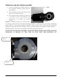
If you have an airflow alarm when the system is powered check the airflow switch. With the blower running and
the source under normal conditions disconnect the leads of the switch and place an ohmmeter across them. The
switch should be closed, less than 2 ohms, if flow is enough to over come stack pressure and blower inlet is clear.
Cover the air cleaner inlet and verify the switch opens. Replace the leads the test is complete.
Control unit
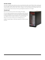
Mount the control unit at eye level for best viewing of the display.
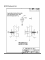
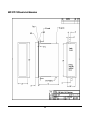
Cut out for panel mounting is shown in the drawing section. Insert the
control unit through the cut out hole. Insert the panel mounting hardware
in the slots provided in the top and bottom of the control unit from the
rear. Tighten the screws until the control unit is securely held in place.
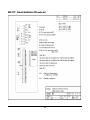
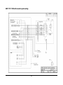
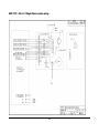
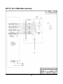
Wire the control unit per drawing section and Energized power.
NOTE: Controller requires a step down transformer for 220Vac 50/60hz
operation.
21