1
Release Note
Software Version 2.8.1
For AT-8800, Rapier i, AT-8700XL, AT-8600,
AT-9900, x900-48FE, AT-8900 and AT-9800 Series
Switches
and AR400 and AR700 Series Routers
Introduction .......................................................................................................4
Upgrading to Software Version 2.8.1 .................................................................5
Backwards Compatibility Issue when Upgrading ......................................... 5
Overview of New Features .................................................................................6
System Enhancements ....................................................................................... 9
Clearing System Parameters ....................................................................... 9
Extended Monitoring of CPU Utilisation ...................................................... 9
Command Reference Updates .................................................................. 11
Command Line Interface (CLI) Enhancements .................................................. 15
More flexibility in Separating Parameters and Values ................................. 15
Additional Shortcuts when Editing ............................................................ 17
Command Reference Updates .................................................................. 18
File System Enhancement ................................................................................. 21
Command Reference Updates .................................................................. 21
Switching Enhancements ................................................................................. 25
Ordering Hardware Filters in 48-Port Switches .......................................... 25
Limiting Rapid MAC Movement ................................................................ 27
Route Update Queue Length .................................................................... 29
Removing a Description from a Switch Port .............................................. 30
Securing a Single VLAN through Switch Filters .......................................... 30
Change of Debug Command Syntax ........................................................ 32
Enhanced Static Switch Filtering on Ports within a Trunk Group ................ 32
Ethernet Protection Switching Ring (EPSR) ................................................ 32
Command Reference Updates .................................................................. 33
PPPoE Access Concentrator .............................................................................. 47
Command Reference Updates .................................................................. 47
MSTP Enhancement .........................................................................................50
Command Reference Updates .................................................................. 50
STP Enhancement ............................................................................................ 51
Command Reference Updates .................................................................. 51
Asynchronous Port Enhancement ..................................................................... 52
Making Asynchronous Ports Respond More Quickly .................................. 52
Command Reference Updates .................................................................. 53
Internet Group Management Protocol (IGMP) Enhancements ...........................55
IGMP Proxy on x900 Series Switches ......................................................... 55
IGMP filtering extended to all IGMP message types .................................. 57
Monitoring reception of IGMP general query messages ............................ 59
Command Reference Updates .................................................................. 60
Internet Protocol (IP) Enhancements .................................................................66
Expanded number of Eth interfaces per physical interface ......................... 66
Expanded IP Troubleshooting .................................................................... 66
2
Release Note
IP Route Preference Options ..................................................................... 66
IPv4 Filter Expansion ................................................................................. 67
Enhancements to Display of UDP Connections over IPv4 ........................... 68
Waiting for a Response to an ARP Request ............................................... 68
Adding Static ARP Entries with Multicast MAC Addresses ......................... 69
Enhanced Static ARP Entry Filtering on Ports within a Trunk Group ........... 70
Command Reference Updates .................................................................. 71
IPv6 Enhancements .......................................................................................... 80
Display of UDP Connections over IPv6 ...................................................... 80
IPv6 Tunnel Expansion .............................................................................. 80
Command Reference Updates .................................................................. 81
L2TP Enhancements .........................................................................................82
Decoding Debug Output and Setting a Time Limit for Debugging ............. 82
Resetting General L2TP Counters .............................................................. 83
Handling PPP Link Negotiation Failures ..................................................... 83
Command Reference Updates .................................................................. 84
Open Shortest Path First Enhancements ........................................................... 89
OSPF Interface Password .......................................................................... 89
NSSA Translator Role ................................................................................ 89
Redistributing External Routes .................................................................. 91
Command Reference Updates .................................................................. 94
BGP Enhancements ........................................................................................ 102
BGP Backoff Lower Threshold ................................................................ 102
BGP Peer and Peer Template Enhancements ........................................... 103
Displaying Routes Learned from a Specific BGP Peer ............................... 104
Command Reference Updates ................................................................ 105
MLD and MLD Snooping Enhancements ........................................................112
MLD Packet Formats ............................................................................... 112
ICMP type for MLDv2 Reports ................................................................ 112
MLD Snooping Group Membership Display ............................................ 113
Change of Maximum Query Response Interval for MLD .......................... 113
Command Reference Updates ................................................................ 114
Extension to Range of Classifier fields for x900 Switches ................................117
Command Reference Updates ................................................................ 117
QoS Enhancements ........................................................................................ 125
Port Groups ............................................................................................ 125
Storm protection .................................................................................... 126
Command Reference Updates ................................................................ 128
Secure Copy (SCP) .........................................................................................142
Configuring Secure Copy ....................................................................... 142
Loading using Secure Copy .................................................................... 144
Uploading using Secure Copy ................................................................. 145
Command Reference Updates ................................................................ 147
SSL Counter Enhancement .............................................................................158
Command Reference Updates ................................................................ 158
Firewall Enhancements ................................................................................... 160
Firewall Licencing ................................................................................... 160
Disabling SIP ALG Call ID Translation ....................................................... 160
Displaying SIP ALG Session Details .......................................................... 161
Firewall Policy Rules Expansion ............................................................... 161
Displaying a Subset of Policy Rules .......................................................... 162
Command Reference Updates ................................................................ 162
Enhancements to IPsec/VPN ...........................................................................169
Responding to IPsec Packets from an
Unknown Tunnel ............................................................................. 169
Modifying the Message Retransmission Delay ......................................... 170
Retrying ISAKMP Phase 1 and 2 Negotiations ......................................... 171
VPN Tunnel Licencing ............................................................................. 172
Software Version 2.8.1
C613-10477-00 REV B
Software Version 2.8.1
3
Command Reference Updates ................................................................ 173
SNMP MIBs .................................................................................................... 186
SHDSL Line MIB ...................................................................................... 186
Logging SNMP operation ........................................................................ 187
Traps on OSPF state changes .................................................................. 188
Trap on VRRP topology changes ............................................................. 189
Traps on MSTP state and topology changes ............................................ 189
Restart Log ............................................................................................. 190
Trap on Login Failures ............................................................................. 190
VLAN-based port state changes .............................................................. 190
Trap on Memory Levels ........................................................................... 191
Command Reference Updates ................................................................ 192
CDP over WAN Interfaces .............................................................................. 193
Command Reference Updates ................................................................ 193
Permanent Assignments on AR400 Series Routers ..........................................197
Software Version 2.8.1
C613-10477-00 REV B
4
Introduction
Release Note
Introduction
Allied Telesis announces the release of Software Version 2.8.1 on the products
in the following table. This Release Note describes the new features and
enhancements.
Product series
Models
x-900-48FE
x-900-48FE, x-900-48FE-N
AT-9900
AT-9924T, AT-9924SP, AT-9924T/4SP
AT-8900
AT-8948
AT-9800
AT-9812T, AT-9816GB
Rapier i
Rapier 24i, Rapier 48i, Rapier 16fi
AT-8800
AT-8824, AT-8848
AT-8700XL
AT-8724XL, AT-8748XL
AT-8600
AT-8624T/2M, AT-8624PoE, AT-8648T/2SP
AR700
AR725, AR745, AR750S, AR770S
AR400
AR415S, AR440S, AR441S, AR442S, AR450S
The product series that each feature and enhancement applies to are shown in
“Overview of New Features” on page 6. This Release Note should be read in
conjunction with the Installation and Safety Guide or Quick Install Guide,
Hardware Reference, and Software Reference for your router or switch. These
documents can be found on the Documentation and Tools CD-ROM packaged
with your router or switch, or:
www.alliedtelesis.com/support/software
This Release Note has the following structure:
1.
Upgrading to Software Version 2.8.1
This section lists the names of the files that may be downloaded from the
web site.
2.
Overview of New Features
This section lists the new features and shows the product families on which
each feature is supported.
3.
Descriptions of New Features
These sections describe how to configure each new feature.
Caution: Information in this document is subject to change without notice and
does not represent a commitment on the part of Allied Telesis Inc. While every
effort has been made to ensure that the information contained within this
document and the features and changes described are accurate, Allied Telesis
Inc. can not accept any type of liability for errors in, or omissions arising from,
the use of this information.
Software Version 2.8.1
C613-10477-00 REV B
Software Version 2.8.1
5
Upgrading to Software Version 2.8.1
Software Version 2.8.1 is available as a flash release that can be downloaded
directly from the Software/Documentation area of the Allied Telesis website:
www.alliedtelesis.com/support/software
Software versions must be licenced and require a password to activate. To
obtain a licence and password, contact your authorised Allied Telesis
distributor or reseller.
The following table lists the file names for Software Version 2.8.1.
Product name
Release file
GUI resource file
CLI help file
AT-9924T/4SP
89-281.rez
9924_281-00_en_d.rsc
89-281a.hlp
AT-9924SP
89-281.rez
9924_281-00_en_d.rsc
89-281a.hlp
AT-9924T/4SP
89-281.rez
9924_281-00_en_d.rsc
89-281a.hlp
AT-8948
89-281.rez
—
89-281a.hlp
x900-48FE
89-281.rez
—
89-281a.hlp
AT-9812T
sb-281.rez
9812_281-00_en_d.rsc
98-281a.hlp
AT-9816GB
sb-281.rez
9816_281-00_en_d.rsc
98-281a.hlp
Rapier 24i
86s-281.rez
r24i_281-00_en_d.rsc
rp-281a.hlp
Rapier 48i
86s-281.rez
r16i_281-00_en_d.rsc
rp-281a.hlp
Rapier16fi
86s-281.rez
r48i_281-00_en_d.rsc
rp-281a.hlp
AT-8824
86s-281.rez
8824_281-00_en_d.rsc
88-281a.hlp
AT-8848
86s-281.rez
8848_281-00_en_d.rsc
88-281a.hlp
AT-8724XL
87-281.rez
8724_281-00_en_d.rsc
87-281a.hlp
AT-8748XL
87-281.rez
8748_281-00_en_d.rsc
87-281a.hlp
AT-8624PoE
sr-281.rez
—
86-281a.hlp
AT-8624T/2M
sr-281.rez
sr24_281-00_en_d.rsc
86-281a.hlp
AT-8648T/2SP
sr-281.rez
—
86-281a.hlp
AR770S
55-281.rez
—
700-281a.hlp
AR750S
55-281.rez
750s_281-00_en_d.rsc
700-281a.hlp
AR725
52-281.rez
725_281-00_en_d.rsc
700-281a.hlp
AR745
52-281.rez
745_281-00_en_d.rsc
700-281a.hlp
AR440S
54-281.rez
440s_281-00_en_d.rsc
400-281a.hlp
AR441S
54-281.rez
441s_281-00_en_d.rsc
400-281a.hlp
AR442S
54-281.rez
442s_281-00_en_d.rsc
400-281a.hlp
AR415S
54-281.rez
415s_281-00_en_d.rsc
400-281a.hlp
AR450S
54-281.rez
450s_281-00_en_d.rsc
400-281a.hlp
Backwards Compatibility Issue when Upgrading
The asexternal parameter of the set ospf command has changed. See OSPF
backward compatibility).
Software Version 2.8.1
C613-10477-00 REV B
6
Overview of New Features
Release Note
Overview of New Features
AT-9900
x900-48FE
AT-8900
AT-9800
AT-8600
AT-8700XL
AT-8800
Rapier
AR750S
AR7x5
AR400
The following table lists the new features and enhancements by product series.
For supported models, see “Introduction” on page 4.
System: Clearing System Parameters
9 9 9 9 9 9 9 9 9 9 9
System: Extended Monitoring of CPU Utilisation
9 9 9 9 9 9 9 9 9 9 9
CLI: Command Line Interface (CLI) Enhancements
9 9 9 9 9 9 9 9 9 9 9
File System: File System Enhancement
9 9 9 9 9 9 9 9 9 9 9
9 9 9 9
Switching: Ordering Hardware Filters in 48-Port Switches
Switching: Limiting Rapid MAC Movement
9 9 9
Switching: Route Update Queue Length
9 9 9
Switching: Removing a Description from a Switch Port
9
9 9 9 9 9 9 9 9 9
9 9 9 9
Switching: Securing a Single VLAN through Switch Filters
Switching: Change of Debug Command Syntax
9
9
Switching: Enhanced Static Switch Filtering on Ports within a
Trunk Group
9 9 9 9 9
9 9 9
Switching: Ethernet Protection Switching Ring (EPSR)
MSTP: MSTP Enhancement
9 9 9 9
9 9 9
STP: STP Enhancement
9 9 9 9 9 9 9 9
Asyn Ports: Making Asynchronous Ports Respond More
Quickly
9 9 9 9 9 9 9 9 9 9 9
PPPoE: PPPoE Access Concentrator
9 9 9 9 9
9 9 9 9
9 9 9
IGMP: IGMP Proxy on x900 Series Switches
IGMP: IGMP filtering extended to all IGMP message types
9 9 9 9 9 9 9 9 9 9 9
IGMP: Monitoring reception of IGMP general query messages
9 9 9 9 9 9 9 9 9 9 9
IP: Expanded number of Eth interfaces per physical interface
9 9 9
IP: Expanded IP Troubleshooting
9 9 9 9 9 9 9 9 9 9 9
IP: IP Route Preference Options
9 9 9 9 9 9 9 9 9 9 9
IP: IPv4 Filter Expansion
9 9 9 9 9 9 9 9 9 9 9
IP: Enhancements to Display of UDP Connections over IPv4
9 9 9 9 9 9 9 9 9 9 9
IP: Waiting for a Response to an ARP Request
9 9 9 9 9 9 9 9 9 9 9
IP: Adding Static ARP Entries with Multicast MAC Addresses
9 9 9 9 9 9 9 9 9 9 9
IP: Enhanced Static ARP Entry Filtering on Ports within a
Trunk Group
IPv6: Display of UDP Connections over IPv6
9 9 9 9 9 9 9 9
9 9 9 9 9
9 9 9 9
Software Version 2.8.1
C613-10477-00 REV B
AT-9900
x900-48FE
AT-8900
AT-9800
AT-8600
AT-8700XL
AT-8800
Rapier
AR750S
AR7x5
7
AR400
Software Version 2.8.1
9
IPv6: IPv6 Tunnel Expansion
L2TP: Decoding Debug Output and Setting a Time Limit for
Debugging
9 9 9 9 9
9 9 9 9
L2TP: Resetting General L2TP Counters
9 9 9 9 9
9 9 9 9
L2TP: Handling PPP Link Negotiation Failures
9 9 9 9 9
9 9 9 9
OSPF: OSPF Interface Password
9 9 9 9 9 9 9 9 9 9 9
OSPF: NSSA Translator Role
9 9 9 9 9 9 9 9 9 9 9
OSPF: Redistributing External Routes
9 9 9 9 9 9 9 9 9 9 9
BGP: BGP Backoff Lower Threshold
9 9 9 9 9
9 9 9 9
BGP: BGP Peer and Peer Template Enhancements
9 9 9 9 9
9 9 9 9
BGP: Displaying Routes Learned from a Specific BGP Peer
9 9 9 9 9
9 9 9 9
MLD: MLD Packet Formats
9 9 9 9 9
9 9 9 9
MLD: ICMP type for MLDv2 Reports
9 9 9 9 9
9 9 9 9
9 9
9 9 9 9
9 9 9 9 9
9 9 9 9
MLD: MLD Snooping Group Membership Display
MLD: Change of Maximum Query Response Interval for MLD
Classifier: Extension to Range of Classifier fields for x900
Switches
9 9 9
QoS: Port Groups
9 9 9
QoS: Storm protection
9 9 9
SCP: Configuring Secure Copy
9 9 9 9 9 9 9 9 9 9 9
SCP: Loading using Secure Copy
9 9 9 9 9 9 9 9 9 9 9
SCP: Uploading using Secure Copy
9 9 9 9 9 9 9 9 9 9 9
SSL: SSL Counter Enhancement
9 9 9 9 9 9 9 9 9 9 9
Firewall: Firewall Licencing
9 9 9 9 9
Firewall: Disabling SIP ALG Call ID Translation
9 9 9 9 9
Firewall: Displaying SIP ALG Session Details
9 9 9 9 9
Firewall: Firewall Policy Rules Expansion
9 9 9 9 9
Firewall: Displaying a Subset of Policy Rules
9 9 9 9 9
IPSEC/VPN: Responding to IPsec Packets from an Unknown
Tunnel
9 9 9 9 9
IPSEC/VPN: Modifying the Message Retransmission Delay
9 9 9 9 9
IPSEC/VPN: Retrying ISAKMP Phase 1 and 2 Negotiations
9 9 9 9 9
IPSEC/VPN: VPN Tunnel Licencing
9 9 9 9 9
SNMP MIBs: SHDSL Line MIB
9
SNMP MIBs: Logging SNMP operation
9 9 9 9 9 9 9 9 9 9 9
Software Version 2.8.1
C613-10477-00 REV B
9
9
AT-9900
x900-48FE
AT-8900
AT-9800
AT-8600
AT-8700XL
AT-8800
Rapier
AR750S
Release Note
AR7x5
Overview of New Features
AR400
8
SNMP MIBs: Traps on OSPF state changes
9 9 9 9 9 9 9 9 9 9 9
SNMP MIBs: Trap on VRRP topology changes
9 9 9 9 9 9 9 9 9 9 9
9 9 9 9
SNMP MIBs: Traps on MSTP state and topology changes
9 9 9
SNMP MIBs: Restart Log
9 9 9 9 9 9 9 9 9 9 9
SNMP MIBs: Trap on Login Failures
9 9 9 9 9 9 9 9 9 9 9
SNMP MIBs: VLAN-based port state changes
9 9 9 9 9 9 9 9 9 9 9
SNMP MIBs: Trap on Memory Levels
9 9 9 9 9 9 9 9 9 9 9
CDP: CDP over WAN Interfaces
9 9 9 9 9
Permanent Assignments on AR400 Series Routers
9
9 9 9 9
Software Version 2.8.1
C613-10477-00 REV B
Software Version 2.8.1
9
System Enhancements
This Software Version includes the following enhancements to system
commands:
■
Clearing System Parameters
■
Extended Monitoring of CPU Utilisation
This section describes the enhancements. The new and modified commands to
implement them are described in Command Reference Updates.
Clearing System Parameters
The option none has been added to the following commands:
set system name={name|none}
set system contact={contact-name|none}
set system location={location|none}
This allows you to clear a previously specified system name, contact name or
location. For example, to clear the system name, use one of the commands:
set sys nam=none
set sys nam=””
set sys nam=
set sys nam
Command Changes
The following table summarises the modified commands:
Command
Change
set system name
New none option for name parameter
set system contact
New none option for contact parameter
set system location
New none option for location parameter
Extended Monitoring of CPU Utilisation
This Software Version includes a new feature for monitoring CPU utilisation.
You can now set the router or switch to capture data about which specific
functions the CPU is executing, and the level of instantaneous usage the CPU is
experiencing. This allows you, in conjunction with your authorised distributor
or reseller, to diagnose the causes of high rates of CPU utilisation on the router
or switch.
You can set the router or switch to capture data continuously, or only when the
CPU experiences a specific level of instantaneous usage. The router or switch
holds up to 500 entries (10 seconds) of data about CPU utilisation.
Software Version 2.8.1
C613-10477-00 REV B
10
System Enhancements
Release Note
To capture data when the CPU is experiencing a specific amount of
instantaneous usage, set the start and start percentages with the command:
activate cpu extended start=1..100 [stop=1..100]
When a start percentage is set, the router or switch automatically disables
extended monitoring once it has 500 data entries.
To enable extended monitoring, use the command:
enable cpu extended
This command also lets you capture data immediately, without first setting
start and stop percentages. This adds data entries continuously, until you stop
it. Only the last 10 seconds of data entries are stored.
To stop capturing data, and reset the start and stop parameters if they are set,
use the command:
disable cpu extended
To remove data entries and reset the start and stop parameters in the activate
cpu extended command, use the command:
reset cpu utilisation
This command interrupts active data capturing for a specific event. However,
monitoring remains enabled, and continues to collect data. This means you can
capture data for a particular event without having to disable and re-enable this
feature.
Command Changes
The following table summarises the new and modified commands:
Command
Change
activate cpu extended
New command.
disable cpu extended
New command.
enable cpu extended
New command.
reset cpu utilisation
Modified command.
show cpu
New extended parameter in command.
New output field when extended parameter is used.
Software Version 2.8.1
C613-10477-00 REV B
Software Version 2.8.1
11
Command Reference Updates
This section describes each new command and the changed portions of
modified commands and output screens. For modified commands and output,
the new parameters, options, and fields are shown in bold.
activate cpu extended
Syntax
Description
ACTivate CPU EXTended STARt=1..100 [STOp=1..100]
This new command lets you set monitoring so that it captures data when the
CPU experiences a specific amount of instantaneous usage.
The start parameter sets the percentage of utilisation the CPU must equal or
exceed before it can begin capturing data. When CPU utilisation reaches the
parameter, the router or switch begins capturing data. It continues until
utilisation falls below the stop parameter, or until it captures 500 entries (10
seconds worth).
The stop parameter sets the percentage of utilisation the CPU must reach to
stop data capturing. If CPU utilisation falls below the stop percentage before
the router or switch has 500 data entries, then the router or switch resumes data
capturing the next time utilisation reaches the start percentage. When the
router or switch has 500 entries, it stops collecting data.
Example
To capture extended CPU utilisation data when CPU utilisation exceeds 70%
and until it falls below 50%, use the command:
act cpu ext star=70 sto=50
disable cpu extended
Syntax
DISable CPU EXTended
Description
This new command stops data capture of CPU utilisation, and resets
parameters in the activate cpu extended command.
Example
To stop capturing extended CPU utilisation data, use the command:
dis cpu ext
enable cpu extended
Syntax
Description
Example
ENAble CPU EXTended
This new command lets you capture up to 500 data entries (10 seconds) of CPU
utilisation data. Extended monitoring is disabled by default. This command
takes effect when you enter it, or use the activate cpu extended command to
collect data during specific usage levels.
To begin capturing extended CPU utilisation data, use the command:
ena cpu ext
Software Version 2.8.1
C613-10477-00 REV B
12
System Enhancements
Release Note
reset cpu utilisation
Syntax
Description
Example
RESET CPU UTIlisation
This command, which resets all CPU utilisation percentages, has been
modified to include resetting any start and stop percentages set with the
activate cpu extended command. It also removes any data captured during
extended utilisation monitoring, and clears this output from the show cpu
command.
To reset the CPU utilisation, use the command:
reset cpu util
set system contact
Syntax
SET SYStem CONtact={contact-name|NONE}
The contact parameter specifies the contact name, which is:
■
displayed in the output of the show system command
■
stored in the MIB object sysContact
If the new option none is specified, no contact name is defined. Any existing
contact name is cleared. The default is none.
set system location
Syntax
SET SYStem LOCation={location|NONE}
The location parameter specifies the location of the router or switch, which is:
■
displayed in the output of the show system command
■
stored in the MIB object sysLocation
If the new option none is specified, no location is defined. Any existing
location is cleared. The default is none.
set system name
Syntax
SET SYStem NAMe={name|NONE}
The name parameter specifies the system name of the router or switch, which
is:
■
displayed in the output of the show system command
■
displayed in the CLI prompt so you know which router or switch you are
configuring
■
stored in the MIB object sysName
If the new option none is specified, no name is defined. Any existing name is
cleared. The default is none.
Software Version 2.8.1
C613-10477-00 REV B
Software Version 2.8.1
13
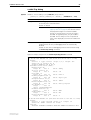
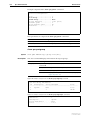
show cpu
Syntax
Description
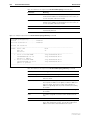
SHow CPU [EXTended]
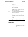
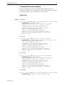
The new extended parameter in this command displays information about
extended CPU utilisation data.
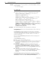
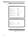
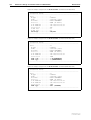
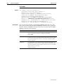
Figure 1: Example output from the show cpu extended command
CPU Utilisation ( as a percentage )
---------------------------------------Maximum since router restarted ..... 100
Maximum over last 5 minutes ........ 100
Average since router restarted ..... 5
Average over last 5 minutes ........ 6
Average over last minute ........... 7
Average over last 10 seconds ....... 41
Average over last second ........... 100
---------------------------------------Extended CPU Information
-----------------------------------------------------------State ............... Enabled
Current Time ........ 21:44:49 (04aa9a34 / 2573941241)
Current Install ..... 54-281.rez (5012892)
Start percent ....... Stop percent ........ msSM
Timestamp Util
Caller Return1 Return2 Return3
-----------------------------------------------------------04aa9a34 2573927208 100 0021a384 00031c0c 00027e8c 0021a57c
04aa9a20 2573907218 100 0021a384 00031c0c 00027e8c 0021a57c
04aa9a0c 2573887230 100 0021a4b0 00031c0c 00027e8c 0021a57c
.
.
.
Software Version 2.8.1
C613-10477-00 REV B
14
System Enhancements
Release Note
Table 1: New parameters in output of the show cpu=extended command
Example
Parameter
Meaning
State
Whether extended CPU utilisation is enabled.
Current Time
Current time in hh:mm:ss format. The time in
milliseconds since midnight, and the current timestamp
are also in brackets.
Current Install
Current installed release, with the size of the release in
brackets.
Start percent
Percentage of utilisation that the CPU must reach, if any,
before the router or switch can begin capturing
extended CPU utilisation data. A “-” shows if no
percentage is set.
Stop percent
Percentage of utilisation that the CPU must fall below
before the router or switch stops capturing extended
CPU utilisation data.
msSM
Time when the router or switch captured the CPU
utilisation sample. The time format is milliseconds since
midnight, in hexadecimal notation.
Timestamp
Time when the router or switch captured the CPU
utilisation sample. The time format is microseconds
since the router or switch last restarted. This figure
wraps at 4 294 967 295 to return to 0.
Util
Percentage of instantaneous CPU utilisation.
Caller
Return address of the function that the CPU is
executing.
Return 1, Return 2, Return 3
Return addresses for function calls on the CPU stack.
To display the extended CPU utilisation data, use the command:
sh cpu ext
Software Version 2.8.1
C613-10477-00 REV B
Software Version 2.8.1
15
Command Line Interface (CLI)
Enhancements
The CLI has been enhanced in the following ways:
■
More flexibility in Separating Parameters and Values
■
Additional Shortcuts when Editing
■
New command show command history that displays past commands.
Please note that it replaces the Ctrl-C shortcut.
■
You can now use the create config command to also set the router or
switch to use the new configuration file.
This section describes the enhancements. The new and modified commands to
implement them are described in Command Reference Updates.
More flexibility in Separating Parameters and Values
The CLI has been enhanced to give you the flexibility of choosing whether the
equals sign should be required between parameters and their related values in
the syntax.
Parameters are keywords in a command that define the object or details of the
action. Parameter values can be numbers or text, or can come from a list of
items. Now you can set the syntax so that parameters and values can be
separated by either one of the following:
■
an equals sign (=)
■
a single space
The set command assignmentoperator command lets you change the syntax.
When using aliases, we suggest you use the = sign in the syntax to link
parameters with their values. Otherwise, if you separate a parameter with a
space, a matching alias could erroneously be substituted for the value. Note
that certain command handlers, such as STT, PERM, and ACC, always require
the = sign.
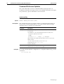
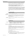
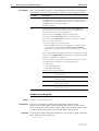
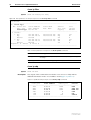
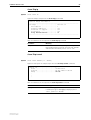
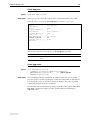
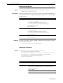
Parts of a Command
A command is a sequence of keywords and values that define an action for the
router or switch to perform. The Software Reference uses terms in the
following figure and table when describing commands.
keywords
add ip rip interface=vlan2 auth=md5 ip=ipadd
action
value
parameters
Software Version 2.8.1
C613-10477-00 REV B
option
placeholder
cli-command-parts
16
Command Line Interface (CLI) Enhancements
Release Note
Command Part Description
Keyword
A generic term for a predefined sequence of characters that the CLI
treats as a single unit.
Actions, parameters, and some parameter values are keywords.
Keywords are not case sensitive. In this Software Reference and the
online help, uppercase letters indicate minimum keyword abbreviations.
Action
The first keyword in a command. This defines the type of operation to
perform. Actions do not have values.
Parameter
Additional keywords that define:
• the object of the action (for example, “ip rip” in the figure above)
• the details of the action (for example, “auth” in the figure above)
Parameters are optional or required, may accept values, and are not case
sensitive. Spaces must separate parameters.
Value
The value assigned to a parameter. Depending on the parameter, a value
can be:
• an item from a list of option keywords
• a number
• arbitrary text
Values are optional or required. Enter values with the syntax
parameter=value or parameter value (for details, see Command
Reference Updates). Most values are not case sensitive, except for
text, such as passwords.
Option
A keyword that is one of a pre-defined list of values that a parameter
can accept.
Placeholder
A format convention that describes the value a parameter can accept.
Instead of typing the placeholder, replace it with an appropriate value.
In this Software Reference, placeholders are printed in lowercase italic
font.
Default
The value the router or switch uses as the parameter when you do not
enter one but the parameter requires one.
Command Changes
The following table summarises the new command.
Command
Description
set command assignmentoperator
New command that sets the assignment operator
of the command parser to allow either an equals
sign or a space between the parameter as the
value.
Software Version 2.8.1
C613-10477-00 REV B
Software Version 2.8.1
17
Additional Shortcuts when Editing
You can now move the cursor to the beginning or end of lines by using single
keys on the keyboard.
To move the cursor to the...
You could only press... Now you can also press the...
beginning of the command
line
Ctrl+A
Home key
end of the command line
Ctrl+E
End key
Command Changes
The following table summarises the changes new and modified commands.
Software Version 2.8.1
C613-10477-00 REV B
Command
Description
show command history
New command that displays past commands.
Please note that it replaces the Ctrl-C shortcut.
create config
New set option that lets you set the switch to the
configuration file that you create.
18
Command Line Interface (CLI) Enhancements
Release Note
Command Reference Updates
This section describes each new command and the changed portions of
modified commands and output screens. For modified commands and output,
new parameters, options and fields are shown in bold.
create config
Syntax
Description
CREate CONfig=filename [SET]
This command now lets you set the switch to a configuration file when you
create it. This command still requires a user with security officer privilege
when the router or switch is in security mode.
Parameter
Description
CONfig
Name of the configuration file or script to create. If one already exists,
it is replaced.
The filename is in the format [device:]filename.ext and can be:
• uppercase and lowercase letters
• digits
• # $ % & ! ' ( ) + , - . ; = @ [ ] ^ _ ` { } ~ and space
device indicates the physical location where the file is stored. The
default is flash.
.ext is an 3-letter extension, such as .txt or .scp.
Invalid characters are * “ | \ : ? / < >
Default: no default
SET
Example
Sets the switch to use the configuration file or script specified by
filename when the switch boots up again.
To save the current dynamic configuration to a script file called test.cfg, use the
command:
cre con=test.cfg
Software Version 2.8.1
C613-10477-00 REV B
Software Version 2.8.1
19
set command assignmentoperator
Syntax
Description
SET COMmand {ASSignmentoperator=[Equals|SPaceorequals]}
This new command sets the assignment operator of the command parser
thereby defining the format of the command syntax for the CLI.
Parameter
Description
ASSignmentoperator
Defines the operator between parameters when assigning values.
Default: Equals
Equals
Requires users to enter = sign. To ensure clarity
and accuracy, we recommend always using the =
sign.
SPaceorequals
Lets users enter either the = sign or just leave a
single space between parameters.
The following commands have the same effect. Note that the first one is clearer
because of the = sign.
add ip rou=172.16.9.0 mask=255.255.255.0 int=vlan1
next=172.16.8.82 met=1
add ip rou 172.16.9.0 mask 255.255.255.0 int vlan1 next
172.16.8.82 met 1
Take care when using aliases because they match any whole word on the
command line. Therefore, if you separate a parameter with a space, a matching
alias could erroneously be substituted for the value.
Note that certain command handlers, such as those for STT, PERM, and ACC,
always require the = sign.
Example
To set the command processor so that you can enter a space between
parameters and values on the command line, use the command:
set com ass=sp
Software Version 2.8.1
C613-10477-00 REV B
20
Command Line Interface (CLI) Enhancements
Release Note
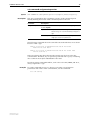
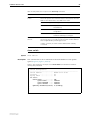
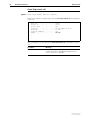
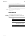
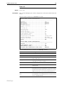
show command history
Syntax
Description
SHow COMmand History
This new command replaces the Ctrl-C keyboard shortcut, and displays past
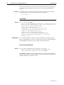
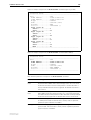
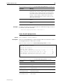
commands for you to select one from the list (Figure 1).
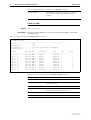
Figure 2: Example output from the show command history command
131
132
133
134
135
136
137
138
139
140
141
142
143
144
145
146
147
148
set vrrp 20 portmon off
set vrrp 20 portmon on
sh vrrp 20
sh vrrp 0
sh vrrp 21
sh vrrp 255
sh vrrp none
sh vrrp any
destroy qos queue2priomap
destroy qos queue2priomap
destroy qos queue2priomap
destroy qos queue2priomap
destroy qos queue2priomap
destroy qos queue2priomap
destroy qos queue2priomap
destroy qos queue2priomap
destroy qos queue2priomap
destroy qos queue2priomap
queue
queue
queue
queue
queue
queue
queue
queue
queue
queue
0
0
0
0
0
0
0
0
0
0
bwclass
bwclass
bwclass
bwclass
bwclass
bwclass
bwclass
bwclass
bwclass
bwclass
2
2
2
2
2
2
2
2
2
2
vrrp
vrrp
vrrp
vrrp
vrrp
vrrp
vrrp
vrrp
vrrp
vrrp
none
any
0
256
17,18
17-19
1
20
all
Enter command number>
Example
To see a list of past commands, use the command:
sh com h
Software Version 2.8.1
C613-10477-00 REV B
Software Version 2.8.1
21
File System Enhancement
This Software Version gives you 4 new commands for working with files.
Command Changes
The following table summarises the new commands:
Command
Change
add file
New command
create file
New command
reset file permanentredirect
New command
show file permanentredirect
New command
Command Reference Updates
This section describes each new command.
add file
Syntax
Description
ADD FIle=filename [COMmand=commandstring]
[SCRipt=scriptname] [PERManentredirect] [LIMIT=limit]
This new command takes output from a specific command or script and adds it
to a text file when you next issue that command or script. This is useful for
collecting debug output. If a file does not exist, one is created. While output is
being redirected, the text file cannot be edited, renamed, deleted, or uploaded.
Parameter
Description
FIle
Name of the text file where you want to send output. One is created
if it does not already exist.The filename is in the format
[device:]filename.txt and can be:
• uppercase and lowercase letters
• digits
• # $ % & ! ' ( ) + , - . ; = @ [ ] ^ _ ` { } ~ and space
device indicates the physical location where the file is stored. The
default is flash.
Default: no default
COMmand
Command whose output is used to generate the text when it is next
issued. Commandstring is the command syntax enclosed in quotes.
Command and script are mutually exclusive.
SCRipt
Script whose output is used to generate the text when it is next issued.
The script is treated as a simple list of commands. Flow control
statements are not accepted to ensure that the extra text the script
produces is not in the output file. Scriptname has the same format as
filename except it must have either a .cfg or .scp extension.
Command and script are mutually exclusive.
Software Version 2.8.1
C613-10477-00 REV B
22
File System Enhancement
Release Note
Parameter (cont.)
Description (cont.)
PERManentredirect
Permanently directs output to the designated text file until the reset
file permanentredirect command is issued or the router or switch is
rebooted.
LIMIT
A decimal number from 0 to 1048576 bytes specifying the maximum
file size.
Default: 204800 bytes
Examples
To add output one time only from the show trace command to a file called
trace.txt command, use the command:
add fi=trace.txt com="show trace"
To permanently add output from the show debug command to a file called
debug2.txt command, use the command:
add fi=debug2.txt com="show debug"
create file
Syntax
Description
CREate FIle=filename [FORCE] [COMmand=commandstring]
[SCRipt=scriptname] [PERManentredirect] [LIMIT=limit]
This new command creates a text file containing output from a specific
command or script. This is useful for collecting debug output. The file cannot
be edited, renamed, deleted, or uploaded while it is receiving input.
Parameter
Description
FIle
Name of the text file that you want to create. The filename is in the
format [device:]filename.txt and can be:
• uppercase and lowercase letters
• digits
• # $ % & ! ' ( ) + , - . ; = @ [ ] ^ _ ` { } ~ and space
device indicates the physical location where the file is stored. The
default is flash.
Default: no default
FORCE
Overwrites the text file if one already exists. If force is not specified
and the file exists, the command has no effect.
COMmand
Command whose output is used to generate the text when it is next
issued. Commandstring is the command syntax enclosed in quotes.
Command and script are mutually exclusive.
SCRipt
Script whose output is used to generate the text when it is next issued.
The script is treated as a simple list of commands. Flow control
statements are not accepted to ensure that the extra text the script
produces is not in the output file. Scriptname has the same format as
filename except it must have either a .cfg or .scp extension.
Command and script are mutually exclusive.
PERManentredirect Permanently directs output to the designated text file until the reset
file permanentredirect command is issued or the router or switch is
rebooted.
Software Version 2.8.1
C613-10477-00 REV B
Software Version 2.8.1
23
Parameter
Description (cont.)
LIMIT
A decimal number from 0 to 1048 576 bytes specifying the maximum
file size.
Default: 204 800 bytes
Example
To permanently direct all debug output from the BGP module to a file named
bgp.txt, use the command:
cre fi=bgp.txt com="enable bgp debug=all" perm
reset file permanentredirect
Syntax
Description
RESET FIle[=filename] PERManentredirect
This new command closes one or all text files so that they no longer receive
input from commands or scripts. After the file closes, it can be uploaded or
edited
Parameter
Description
FIle
Name of the text file to close. If no file is specified, all text files are
closed.
The filename is in the format [device:]filename.txt and can be:
• uppercase and lowercase letters
• digits
• # $ % & ! ' ( ) + , - . ; = @ [ ] ^ _ ` { } ~ and space
device indicates the physical location where the file is stored. The
default is flash.
Default: no default
Example
To reset the bgp.txt file so that it no longer receives output from the enable bgp
debug=all command (previously set), use the command:
reset fi=bgp.txt perm
show file permanentredirect
Syntax
Description
SHow FIle[=filename] PERManentredirect
This new command displays information about one text file or all that are
permanently receiving output from commands or scripts (Figure 3, Table 2).
These files are typically created to collect data during debugging.
The file parameter displays information about a specific text file (Figure 4). The
filename option is in the format [device:]filename.txt and can be:
■
uppercase and lowercase letters
■
digits
■
# $ % & ! ' ( ) + , - . ; = @ [ ] ^ _ ` { } ~ and space
Device indicates the physical location where the file is stored. The default is
flash.
Software Version 2.8.1
C613-10477-00 REV B
24
File System Enhancement
Release Note
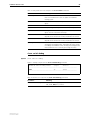
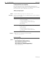
Figure 3: Example output from the show file permanentredirect command
TTY
Current
Limit
File
Instance
Size
--------------------------------------------------17
12345
204800
bgp.txt
Figure 4: Example output from the show file=filename permanentredirect command
File............
TTY Instance....
Current Size....
Limit...........
Input(s)........
bgp.txt
17
12345
204800
COMMAND="enable bgp debug=all"
Table 2: Parameters in output of the show file permanentredirect command
Example
Parameter
Meaning
TTY Instance
Instance number for the TTY device.
Current Size
Size of the text file in bytes.
Limit
Limit of file size in bytes set by the limit parameter.
File
Name of text file.
Input(s)
Commands and scripts that generate input for the text file.
To display all text files receiving output from commands or scripts, use the
command:
sh fi perm
Software Version 2.8.1
C613-10477-00 REV B
Software Version 2.8.1
25
Switching Enhancements
This Software Version includes the following enhancements to switching:
■
Ordering Hardware Filters in 48-Port Switches
■
Limiting Rapid MAC Movement
■
Route Update Queue Length
■
Removing a Description from a Switch Port
■
Securing a Single VLAN through Switch Filters
■
Change of Debug Command Syntax
■
Enhanced Static Switch Filtering on Ports within a Trunk Group
■
Ethernet Protection Switching Ring (EPSR)
This section describes the enhancements. The new and modified commands to
implement them are described in Command Reference Updates.
Ordering Hardware Filters in 48-Port Switches
This feature applies only to the following products: AT-8648, AT-8748, AT-8848,
and the Rapier 48i. These products contain 2 switching instances, which adds
complexity to the filtering process when packets are being sent between
instances.
This Software Version allows you to select between two modes of using
classifier-based packet filtering in 48-port switches: port-specific filters first, or
non port-specific filters first.
You can select different modes using the new set switch hwfilter mode
command. Selecting the right mode when setting up classifier-based packet
filters ensures that packets are filtered as expected across switch instances. The
switch defaults to port-specific filters first. You can change the filtering mode
on the switch by using the command:
set switch hwfilter mode={psf|npsf}
Port-specific filters apply to traffic either ingressing or egressing a particular
port. They use a classifier which specifies the iport or eport parameter. Non
port-specific filters can apply to all traffic travelling through the switch. Non
port-specific filters are created with a classifier that does not have the iport or
eport parameter specified.
Software Version 2.8.1
C613-10477-00 REV B
26
Switching Enhancements
When to Use
Port-Specific Mode
Release Note
Use the port-specific psf mode when you want non port-specific filters to
override the port-specific filters for certain circumstances. In the following
example:
■
the first (port-specific) filter stops all traffic from ingressing port 2
■
the second (port-specific) filter allows traffic with the specific IP address
(192.168.2.2) to ingress port 2
■
the third (non port-specific) filter allows any ARP request (prot=0806) to
ingress and egress all ports
create classifier=1 iport=2
create classifier=2 iport=2 ipsa=192.168.2.2
create classifier=3 prot=0806
add swi hwf classifier=1 action=discard
add swi hwf classifier=2 action=nodrop
add swi hwf classifier=3 action=nodrop
In psf mode, you must enter the port-specific filters first. If you add a
port-specific filter after the non port-specific filters, the switch may still use a
matching non port-specific filter when the packet travels between ports on
different switch instances.
When to Use Non
Port-Specific Mode
Use the non port-specific npsf mode when you want port-specific filters to
override the non port-specific filters for certain circumstances. In the following
example, the second (port-specific) filter stops the first (non port-specific) filter
from discarding packets from port 50:
create class=1 ipsa=192.168.1.254/32
create class=4 ipo=50
add switch hwf class=1 ac=dis
add switch hwf class=4 ac=nod
In npsf mode, you must enter the non port-specific filters first. If you add a non
port-specific filter after the port-specific filters, the switch may not use the non
port-specific filter when the packet travels between ports on different switch
instances.
Changing Modes
You can change the filter mode after filters have been entered. When you
change modes, the filter entries remain in the original order. To see which
mode the switch is in, use the command:
show switch hwfilter
Command Changes
The following table summarises the new and modified commands:
Command
Change
set switch hwfilter mode
New command.
show switch hwfilter
New mode parameter in output.
Software Version 2.8.1
C613-10477-00 REV B
Software Version 2.8.1
27
Limiting Rapid MAC Movement
This Software Version introduces the ability to limit rapid MAC movement.
MAC address thrashing occurs when MAC addresses move rapidly between
one or more ports or trunks. For example, certain MAC addresses are learnt on
one port, then very shortly afterwards are learnt on another port, then learnt on
the original port again, and so on. This typically occurs when there is an
uncontrolled loop on the network.
Disabling a port
There are different ways you can disable a port when thrashing is detected.
These are called thrash actions:
■
learnDisable
Address learning is temporarily disabled on the port.
■
portDisable
The port is logically disabled. Traffic flow is prevented, but the link
remains up. The device at the other end does not notice that the port has
changed status, and the link LEDs at both ends stay on. This is equivalent
to entering the disable switch port command.
■
linkDown
The port is physically disabled and the link is down. This is equivalent to
entering the disable switch port link=disabled command.
■
vlanDisable
The port is disabled only for the VLAN on which thrashing has occurred. It
can still receive and transmit traffic for any other VLANs of which it is a
member.
When a MAC address is thrashing between two ports, only one of those ports
is disabled. When multiple ports are involved, enough ports are disabled to
prevent the storm.
To set a thrash action for a port, use the command:
set switch port={port-list|all}
[thrashaction={learndisable|linkdown|none|portdisable|vla
ndisable}]
To view the thrash action that is set for a port, use the command:
show switch port={port-list|all}
To set a thrash action for a trunk, use one of the commands:
create switch trunk=trunk [port=port-list]
[thrashaction={learndisable|linkdown|none|portdisable|vla
ndisable}]
set switch thrashlimit=trunk
[thrashaction={learndisable|linkdown|none|portdisable|vla
ndisable}]
To view the thrash action that is set for a trunk, use the command:
show switch trunk={trunk}
Software Version 2.8.1
C613-10477-00 REV B
28
Switching Enhancements
Release Note
To view details about disabled ports for VLANs, use one of the commands:
show vlan[={vlan-name|1..4094|all}]
show vlan[=all]
Re-enabling a port
When a port is disabled, either completely or for a specific VLAN, it remains
disabled until it is manually re-enabled in any of the following ways:
■
with SNMP
■
as the result of a reboot
■
by specifying a thrash timeout value along with the thrash action
■
via the CLI
If the vlandisable thrash action has been applied, to re-enable one or more
ports from VLANs to which they belong, use the command:
enable switch port={port-list|all}
vlan[={vlan-name|1..4094|all}]
If either the portdisable or linkdown thrash action has been applied, to
re-enable one or more ports, use the command:
If the learndisable thrash action has been applied, the port is automatically
re-enabled when the defined timeout expires. You cannot manually re-enable
the port.
Port Types
Limiting rapid MAC movement is supported on all port types. It is also
supported on trunked ports.
Command Changes
The following table summarises the new and modified commands:
Command
Change
create switch trunk
New thrashaction parameter.
New thrashtimeout parameter.
enable switch port vlan
New command.
enable switch port vlan
New command.
set lacp
New thrashaction parameter.
New thrashtimeout parameter.
set switch port
New thrashaction parameter.
New thrashtimeout parameter.
New vlanstatustrap parameter.
set switch thrashlimit
New command.
set switch trunk
New thrashaction parameter.
New thrashtimeout parameter.
show lacp
New address learn thrash action parameter.
New address learn thrash timeout parameter.
show switch port
New address learn thrash status parameter.
New address learn thrash action parameter.
New address learn thrash timeout parameter.
New vlan status trap parameter.
Software Version 2.8.1
C613-10477-00 REV B
Software Version 2.8.1
29
Route Update Queue Length
When hardware learning delay is enabled (the default), the switch learns new
routes in software, then places them into a queue for adding to its hardware
routing table. Defaults have been set for the maximum number of entries in the
queue, and depend on the amount of memory installed on the switch, as
shown in the following table:
Memory Size (Mbytes)
Default length
(number of entries)
Maximum possible length
(number of entries)
up to 128
200000
200000
129-256
1000000
1500000
more than 256
3000000
4000000
You can alter the length of the queue, by using the following new command to
specify the maximum number of entries in the queue:
set switch hwrouteupdate=1..maximum
The maximum depends on the amount of memory on the switch, as shown in
the table above.
The purpose of this feature is to enable you to tune the balance between the
memory that the route update process uses, and the speed with which large
route updates are processed.
Output of the show switch command has been expanded to display
information about the queue settings.
Command Changes
The following table summarises the new and modified commands:
Software Version 2.8.1
C613-10477-00 REV B
Command
Change
set switch hwrouteupdate
New command
show lacp
New fields about the hardware route update queue
30
Switching Enhancements
Release Note
Removing a Description from a Switch Port
You can now return the description of a switch port to its original blank value
by entering the following command:
set switch port=port-number description=
and providing no value for the description parameter.
Command Changes
The following table summarises the modified command:
Command
Change
set switch port
Changed description parameter
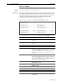
Securing a Single VLAN through Switch Filters
On AT-8824, Rapier 24i, AT-8724XL and AT-8624 switches only (not on 48-port
switches), this enhancement enables you to use switch filters to secure only the
current VLAN, instead of securing all VLANs on the switch. To turn on this
feature, a new command disables “vlansecure” mode for filters (see
“Configuring vlansecure” on page 31).
Without this enhancement (the default situation) a switch filter only allows a
host to access the network through a particular port on the switch. For
example, if you have a PC connected to port 15 in vlan2, and define the
following filter, the PC can only communicate when it is connected to port 15:
add switch filter entry=0 dest=pc-mac-address vlan=2 port=15
action=forward
With this enhancement, the above filter limits the host to accessing vlan2
through port 15, but does not prevent the host from accessing other VLANs
through other ports in vlan2. For example, if the above filter exists and you
move the PC to another port in vlan2, this enhancement prevents the PC from
communicating with devices in vlan2 but allows it access to other VLANs on
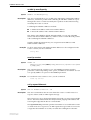
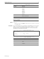
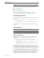
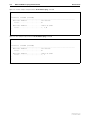
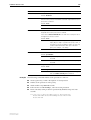
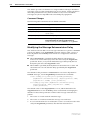
the switch. The following figure shows a PC that has been moved from port 15
to port 16 to illustrate the effect.
Software Version 2.8.1
C613-10477-00 REV B
Software Version 2.8.1
31
Default behaviour
Securing only the VLAN
(vlansecure enabled)
(vlansecure disabled)
port 15
port 16
port 15
vlan2
vlan2
vlan1
vlan1
port 16
swi-filter
Configuring vlansecure
To turn off the default behaviour, so that the filter prevents access to only the
current VLAN when you move the host, use the new command:
disable switch filter vlansecure
To return to the standard filter behaviour, use the new command:
enable switch filter vlansecure
To display which mode the filtering behaviour is in, use the existing command:
show switch filter
This command now displays the additional field VlanSecure, which is either
DISABLED or ENABLED.
Command Changes
The following table summarises the new and modified commands:
Software Version 2.8.1
C613-10477-00 REV B
Command
Change
disable switch filter vlansecure
New command
enable switch filter vlansecure
New command
show switch filter
New VlanSecure field
32
Switching Enhancements
Release Note
Change of Debug Command Syntax
This Software Version includes a change in syntax for the enable switch debug
and disable switch debug commands. To enable or disable debugging on the
switch chip operations, you now use the dev option. Previously, this type of
debugging was enabled or disabled using the m6 parameter. There is no
change in the style or type of debugging information displayed.
To enable debugging of the switch chip operations, use the command:
enable switch debug=dev [other options]
To disable debugging of the switch chip operations, use the command:
disable switch debug=dev
Command Changes
The following table summarises the modified commands:
Command
Change
disable switch debug
New dev option in debug parameter.
enable switch debug
New dev option in debug parameter.
show switch debug
New DEV option in output.
Enhanced Static Switch Filtering on Ports within a
Trunk Group
This Software Version ensures that traffic flow is not interrupted when a port
within a trunk group goes link-down.
In previous Software Versions, when a port that is part of a trunk group goes
link-down, the router or switch drops any traffic that is forwarded by a static
switch filter out of that port.
In this Software Version, when a port that is part of a trunk group goes
link-down, the router or switch modifies any static switch filters defined to
forward traffic out of that port. It modifies the egress port for the switch filter
entry to a port which is link-up within the trunk group. This ensures that traffic
can flow without interruption despite the original port going link-down.
Command Changes
This expansion does not affect any commands.
Ethernet Protection Switching Ring (EPSR)
EPSR is a protection system employed to prevent loops and provide high
resiliency within Ethernet ring based topologies. It offers:
■
A rapid detection and recovery time (in the order of 50 ms, depending on
configuration) if a link or node fails.
■
A faster and more effective alternative to spanning tree based options
when creating resilient ring networks.
Information about EPSR and its commands is shown in the EPSR chapter.
Software Version 2.8.1
C613-10477-00 REV B
Software Version 2.8.1
33
Command Reference Updates
This section describes each new command and the changed portions of
modified commands and output screens. For modified commands and output,
new parameters, options and fields are shown in bold.
create switch trunk
Syntax
Description
CREate SWItch TRunk=trunk [POrt=port-list]
[SPeed={10M|100M|1000M|10G}]
[THRASHAction={LEarndisable|LINKDown|NONE|POrtdisable|V
LANdisable}] [THRASHTimeout={None|1..86400}]
This command creates a trunk group on the switch and optionally adds ports
to the trunk group and sets port speed. must not be in another trunk group
The thrashaction parameter specifies the action the router or switch takes
when it detects MAC address thrashing on a trunk. Thrashing occurs when one
or more ports or trunks repeatedly learn the same MAC addresses, for
example, as a result of a network loop. The router or switch applies the trunk’s
thrashaction to all ports in the trunk.
Take care with the thrashaction parameter because misuse can impair your
network operation.
Set the thrashaction parameter to:
■
none to apply no thrash limiting on the trunk.
■
learndisable to disable MAC address learning on all ports in the thrashing
trunk, until the period specified with the thrashtimeout parameter has
elapsed. The default is learndisable.
■
portdisable or linkdown to disable all ports in the thrashing trunk until
either the period specified by the thrashtimeout parameter has elapsed, or
until the ports or subset of ports in the trunk are re-enabled by the enable
switch port command. If linkdown is specified, the link state is down; if
portdisable is specified, the link state remains up.
■
vlandisable to block all traffic on the VLAN where the address was
learned, on all ports in the thrashing trunk, until either the period specified
by thrashtimeout has elapsed, or until the ports are re-enabled using the
enable switch port vlan command. When thrashaction=vlandisable, there
is only one timer per trunk, so if multiple VLANs have been disabled on a
trunk, the timer starts when the last VLAN was disabled. When the timer
expires, all VLANs are re-enabled on the trunk. When
thrashaction=vlandisable, ingress filtering is automatically enabled on all
ports in the trunk.
The thrashtimeout parameter specifies the time, in seconds, for which the
switch employs the thrash action specified by the thrashaction parameter. The
thrashtimeout cannot be set to none if thrashaction=learndisable. If
thrashtimeout=none, and thrashaction is then changed to learndisable, then
the router or switch automatically changes the thrashtimeout to 1 second.
If none is specified, the trunk is not automatically re-enabled, but individual
ports can be re-enabled by using the enable switch port command for
thrashaction=portdisable or linkdisable, and the enable switch port vlan
command for thrashaction=vlandisable. The default is 1 second.
Software Version 2.8.1
C613-10477-00 REV B
34
Switching Enhancements
Release Note
disable switch debug
Syntax
Description
DISable SWItch DEBug={ARL|DEV|DMA|PHY|ALL}
The m6 parameter is now replaced by the dev parameter in this command.
Debug Option
Description
DEV
Debugging occurs on operations related to the switch chip.
disable switch filter vlansecure
Syntax
Description
DISable SWItch FILter VLANSecure
This new command modifies Layer 2 switch filtering by disabling vlansecure
mode. The vlansecure mode is enabled by default.
When vlansecure mode is disabled and a filter exists for a given host and port,
moving the host to a different port in the same VLAN only stops the host from
accessing that VLAN, not other VLANs. When vlansecure mode is enabled
and a filter exists for a given host and port, moving the host to a different port
blocks the host completely.
Example
To turn off the default filtering behaviour, use the command:
dis swi fil vlan
disable switch port vlan
Syntax
DISable SWItch POrt={port-list|ALL}
VLAN[={vlan-name|1..4094|ALL}]
where:
Description
■
port-list is a port number, range (specified as n-m), or comma-separated list
of numbers and/or ranges. Port numbers start at 1 and end at m, where m
is the highest numbered Ethernet switch port, including uplink ports.
■
vlan-name is a unique name from 1 to 32 characters. Valid characters are
uppercase and lowercase letters, digits, the underscore, and hyphen.
This new command disables one or more ports from VLANs to which they
belong. Once disabled, a port remains a member of the VLAN, but does not
receive or transmit packets from that VLAN.
The port parameter specifies the port or ports to disable. If a trunked port is
specified, all ports in the trunk are disabled. When a VLAN is disabled on a
port, ingress filtering is automatically enabled for that port
The vlan parameter specifies the VLAN or VLANs for which ports are
disabled. Specified ports must be a member of the VLAN. If no value, or all is
specified, the specified ports will be disabled for all VLANs to which they
belong.
Software Version 2.8.1
C613-10477-00 REV B
Software Version 2.8.1
Example
35
To disable the default vlan on port 1, use the command:
dis swi po=1 vlan=1
enable switch debug
Syntax
Description
ENAble SWItch DEBug={ARL|DEV|DMA|PHY|ALL} [OUTPUT=CONSOLE]
[TIMEOUT={1..4000000000|NONE}]
The m6 parameter is now replaced by the dev parameter in this command.
Debug Option
Description
DEV
Debugging is disabled for operations related to the switch chip.
enable switch filter vlansecure
Syntax
Description
ENAble SWItch FILter VLANSecure
This new command returns Layer 2 switch filtering to its default behaviour by
enabling vlansecure mode. The vlansecure mode is enabled by default.
When vlansecure mode is enabled and a filter exists for a given host and port,
moving the host to a different port blocks the host completely. When
vlansecure mode is disabled and a filter exists for a given host and port,
moving the host to a different port in the same VLAN only stops the host from
accessing that VLAN, not other VLANs.
Example
To turn on the default filtering behaviour, use the command:
ena swi fil vlan
enable switch port vlan
Syntax
ENAble SWItch POrt={port-list|ALL}
VLAN[={vlan-name|1..4094|ALL}]
where:
Description
■
port-list is a port number, range (specified as n-m), or comma-separated list
of numbers and/or ranges. Port numbers start at 1 and end at m, where m
is the highest numbered Ethernet switch port, including uplink ports.
■
vlan-name is a unique name from 1 to 32 characters. Valid characters are
uppercase and lowercase letters, digits, the underscore, and hyphen.
This new command enables one or more ports for VLANs to which they
belong. A port is automatically enabled for a VLAN when it is added to that
VLAN, however, it can be disabled using the disable switch port vlan
command, or automatically disabled by thrash limiting or QoS protection.
The port parameter specifies the port or ports to enable. If a trunked port is
specified, all ports in the trunk are enabled.
Software Version 2.8.1
C613-10477-00 REV B
36
Switching Enhancements
Release Note
The vlan parameter specifies the VLAN or VLANs for which ports are enabled.
Specified ports must be a member of the VLAN. If no value or all is specified,
the specified ports are enabled for all VLANs to which they belong.
Note that when a disabled VLAN is re-enabled on a port, the port
automatically has ingress filtering disabled, as long as there are no other
VLANs disabled on the port, and as long as ingress filtering was not previously
enabled by using the set switch port command.
Example
To enable the default vlan on port 1, use the command:
ena swi po=1 vlan=1
set lacp
Syntax
Description
SET LACP PRIOrity=priority
[THRASHAction={LEarndisable|LINkdown|NONE|POrtdisable|V
LANdisable}] [THRASHTimeout={None|1..86400}]
This command modifies the LACP parameters.
The thrashaction parameter specifies the action the router or switch takes
when it detects MAC address thrashing on any trunk created by LACP.
Thrashing occurs when one or more ports or trunks repeatedly learn the same
MAC addresses, for example, as a result of a network loop. The router or
switch applies the trunk’s thrashaction to all ports in the trunk.
Take care with the thrashaction parameter because misuse can impair your
network operation.
Set the thrashaction parameter to:
■
none to apply no thrash limiting on the trunk.
■
learndisable to disable MAC address learning on all ports in the thrashing
trunk, until the period specified with the thrashtimeout parameter has
elapsed. The default is learndisable.
■
portdisable or linkdown to disable all ports in the thrashing trunk until
either the period specified by the thrashtimeout parameter has elapsed, or
until the ports or subset of ports in the trunk are re-enabled by the enable
switch port command. If you specify linkdown, the link state is down; if
you specify portdisable, the link state remains up.
■
vlandisable to block all traffic on the VLAN where the address was
learned, on all ports in the thrashing trunk, until either the period specified
by thrashtimeout has elapsed, or until the ports are re-enabled using the
enable switch port vlan command. When thrashaction=vlandisable, there
is only one timer per trunk, so if multiple VLANs have been disabled on a
trunk, the timer starts when the last VLAN was disabled. When the timer
expires, all VLANs are re-enabled on the trunk. When
thrashaction=vlandisable, ingress filtering is automatically enabled on all
ports in the trunk.
The thrashtimeout parameter specifies the time, in seconds, for which the
switch employs the thrash action specified by the thrashaction parameter. The
thrashtimeout cannot be set to none if thrashaction=learndisable. If
thrashtimeout=none, and thrashaction is then changed to learndisable, then
the router or switch automatically changes the thrashtimeout to 1 second.
Software Version 2.8.1
C613-10477-00 REV B
Software Version 2.8.1
37
If none is specified, the trunk is not automatically re-enabled, but individual
ports can be re-enabled by using the enable switch port command for
thrashaction=portdisable or linkdisable, and the enable switch port vlan
command for thrashaction=vlandisable. The default is 1 second.
set switch hwfilter mode
Syntax
Description
SET SWItch HWFilter MODe={PSF|NPSF}
This new command changes the router or switch’s classifier-based packet filter
mode, and is only valid for models with 48 ports (two switch instances). Use
this command to ensure that packets are filtered as expected on 48-port routers
or switches.
You can change the hardware filter mode after filters have been entered. When
you change modes, the filter entries remain in the original order.
The mode parameter specifies the filtering mode the router or switch is set in.
The default mode is psf.
When you specify psf, the router or switch expects port-specific filters to be
entered first. Use this mode when you want non port-specific filters to override
the port-specific filters for certain circumstances. If you add a port-specific
filter after the non port-specific filters, the router or switch may still use a
matching non port-specific filter when the packet travels between ports on
different switch instances.
When you specify npsf, the router or switch expects non port-specific filters to
be entered first. Use this mode when you want port-specific filters to override
the non port-specific filters for certain circumstances. If you add a non
port-specific filter after the port-specific filters, the router or switch may not
use the port-specific filter when the packet travels between ports on different
switch instances.
Example
To set the hardware filter mode to non port-specific filters first, use the
command:
set swi hwf mod=npsf
set switch hwrouteupdate
Syntax
Description
SET SWItch HWRouteupdate=1..maximum
This new command sets the length of the hardware route update queue.
The hwrouteupdate parameter specifies the maximum possible number of
entries in the queue. The maximum and default values depend on the amount of
memory on the switch, as shown in the following table:
Software Version 2.8.1
C613-10477-00 REV B
Memory Size (Mbytes)
Default length
(number of entries)
Maximum possible length
(number of entries)
up to 128
200000
200000
129-256
1000000
1500000
more than 256
3000000
4000000
38
Switching Enhancements
Example
Release Note
To make the queue as long as possible on a switch with 256Mbytes of memory,
use the command:
set swi hwr=4000000
set switch port
SET SWItch POrt={port-list|ALL} [ACCeptable={ALL|VLAN}]
[BCLimit={NONE|limit] [DESCription=[description]]
[EGResslimit={bandwidth|DEFault}]
[IGMPACtion={DENY|REPlace}]
[IGMPFIlter={NONE|filter-id}]
[IGMPMAxgroup={NONE|1..65535}] [INFILTering={OFF|ON}]
[INTRusionaction={DISAble|DIScard|TRap}]
[LEARn={NONE|0|1..256] [MIRRor={BOTH|NONE|RX|TX}]
[MODe={AUTOnegotiate|MASTer|SLAve}]
[POLarity={MDI|MDIX}] [RELearn={OFF|ON}]
[SPeed={AUTOnegotiate|10MAUTo|10MHALf|10MFUll|10MHAUto|
10MFAuto|100MAUto|100MHALf|100MFUll|100MHAUto|100MFAuto
|1000MHALf|1000MFUll|1000MFAUto}]
[THRASHAction={LEarndisable|LINKDown|NONE|POrtdisable|V
LANdisable}] [THRASHTimeout={None|1..86400}]
[VLANSTAtustrap={ON|OFF}]
Description
This command modifies the value of parameters for switch ports.
The description parameter can now be entered without a value, to remove an
existing description.
The thrashaction parameter specifies the action the router or switch takes
when it detects MAC address thrashing on a port. Thrashing occurs when one
or more ports repeatedly learn the same MAC addresses, for example, as a
result of a network loop.
Take care with the thrashaction parameter because misuse can impair your
network operation.
Set the thrashaction parameter to:
■
none to apply no thrash limiting to the port.
■
learndisable to disable MAC address learning on the port, until the period
specified with the thrashtimeout parameter has elapsed. The default is
learndisable.
■
portdisable or linkdown to disable the port until either the period
specified by the thrashtimeout parameter has elapsed, or until the port is
re-enabled by using the enable switch port command. If you specify
linkdown, the link state is down; if you specify portdisable, the link state
remains up.
■
vlandisable to block all traffic on the VLAN where the address was
learned, until either the period specified by thrashtimeout has elapsed, or
until the port is re-enabled by using the enable switch port vlan
command.
The thrashtimeout parameter specifies the time, in seconds, for which the
switch employs the thrash action specified by the thrashaction parameter. The
thrashtimeout cannot be set to none if thrashaction=learndisable. If
Software Version 2.8.1
C613-10477-00 REV B
Software Version 2.8.1
39
thrashtimeout=none, and thrashaction is then changed to learndisable, then
the router or switch automatically changes the thrashtimeout to 1 second.
If none is specified, the port is not automatically re-enabled, but can be
re-enabled by using the enable switch port command for
thrashaction=portdisable or linkdisable, and the enable switch port vlan
command for thrashaction=vlandisable. The default is 1 second.
The vlanstatustrap parameter specifies whether the switch will send an SNMP
trap whenever a port is enabled or disabled for a VLAN. A port can be disabled
for a VLAN by using the disable switch port command, either when thrashing
is detected on a port and the port’s thrashaction is vlandisable, or when a
storm is detected by QoS storm protection and the stormaction is vlandisable.
If on is specified, a trap is sent. If off is specified, a trap is not sent. The default
is off.
set switch thrashlimit
Syntax
Description
Example
SET SWItch THRASHLimit=5..255
This new command sets the maximum number of times a MAC address can
move between ports, in one second. When the specified limit is reached, the
thrashaction specifed with the set switch port command is applied. The
default thrashlimit is 10.
To set the switch thrash limit to 100 MAC movements per second, use the
command:
set swi thrashl=100
set switch trunk
Syntax
Description
SET SWItch TRunk=trunk [SPeed={10M|100M|1000M|10G}]
[THRASHAction={LEarndisable|LINKDown|NONE|POrtdisable|
VLANdisable}] [THRASHTimeout={None|1..86400}]
This command sets the speed for a specific trunk group on the switch. The
switch supports static 802.3ad link aggregation, and port trunking is also called
link aggregation.
The thrashaction parameter specifies the action the router or switch takes
when it detects MAC address thrashing on a trunk. Thrashing occurs when one
or more ports or trunks repeatedly learn the same MAC addresses, for
example, as a result of a network loop. The router or switch applies the trunk’s
thrashaction to all ports in the trunk.
Take care with the thrashaction parameter because misuse can impair your
network operation.
Set the thrashaction parameter to:
Software Version 2.8.1
C613-10477-00 REV B
■
none to apply no thrash limiting on the trunk.
■
learndisable to disable MAC address learning on all ports in the thrashing
trunk, until the period specified with the thrashtimeout parameter has
elapsed. The default is learndisable.
40
Switching Enhancements
Release Note
■
portdisable or linkdown to disable all ports in the thrashing trunk until
either the period specified by the thrashtimeout parameter has elapsed, or
until the ports or subset of ports in the trunk are re-enabled by the enable
switch port command. If you specify linkdown, the link state is down; if
you specify portdisable, the link state remains up.
■
vlandisable to block all traffic on the VLAN where the address was
learned, on all ports in the thrashing trunk, until either the period specified
by thrashtimeout has elapsed, or until the ports are re-enabled using the
enable switch port vlan command. When thrashaction=vlandisable, there
is only one timer per trunk, so if multiple VLANs have been disabled on a
trunk, the timer starts when the last VLAN was disabled. When the timer
expires, all VLANs are re-enabled on the trunk. When
thrashaction=vlandisable, ingress filtering is automatically enabled on all
ports in the trunk.
The thrashtimeout parameter specifies the time, in seconds, for which the
switch employs the thrash action specified by the thrashaction parameter. The
thrashtimeout cannot be set to none if thrashaction=learndisable. If
thrashtimeout=none, and thrashaction is then changed to learndisable, then
the router or switch automatically changes the thrashtimeout to 1 second.
If none is specified, the trunk is not automatically re-enabled, but individual
ports can be re-enabled by using the enable switch port command for
thrashaction=portdisable or linkdisable, and the enable switch port vlan
command for thrashaction=vlandisable. The default is 1 second.
show lacp
Syntax
Description
SHow LACP
This command displays the state of LACP on the router or switch.
Table 3: Example output from the show lacp command
LACP Information
-----------------------------------------------------------Status .......................... Enabled
Actor System Priority ........... 80-00
Actor System .................... 00-3e-0a-12-00-01
Address learn thrash action ..... Learn Disable
Address learn thrash timeout .... 1 second
LACP Ports ...................... 1-3,5,7,9-12
Active ........................ 1-3,5
Passive ....................... 7,9-12
Software Version 2.8.1
C613-10477-00 REV B
Software Version 2.8.1
41
Table 4: New parameters in output of the show lacp command
Parameter
Description
Address learn thrash The thrashaction value that is applied to any trunks created by
action
LACP. This specifies the action the router or switch takes when the
address learn thrash limit is exceeded on the trunk.
Disable Learning
Learning is disabled on all ports in the trunk
Disable Port
All ports in the trunk are disabled but the links
will remain up
Link Down
All ports in the trunk are disabled and the links
will go down
Disable Vlan
All ports in the trunk are disabled for the
VLAN that thrashing occurring on.
Address learn thrash The thrashtimeout value to apply to any trunks created by LACP. It
timeout
specifies the time, in seconds, for which a trunk remains disabled
after being disabled by thrashing protection.
If ‘None’ is shown, the trunk remains disabled until manually
re-enabled.
show switch
Syntax
Description
SHow SWItch
This command now shows information about the hardware route update
queue (Figure 5, Figure 6, Table 5).
Figure 5: New parameters in output of the show switch command when hardware
learning delay is disabled
Switch Configuration
----------------------------------------------------------Switch Address ............. 00-00-cd-12-78-03
Learning ................... ON
Ageing Timer ............... ON
IP route:
Learn delay ............. OFF
queue limit ....... 1000000
queue maximum ..... 1500000
queue default ..... 1000000
Updating hardware(status) 0 (Pending)
.
.
.
Software Version 2.8.1
C613-10477-00 REV B
42
Switching Enhancements
Release Note
Figure 6: New parameters in output of the show switch command when hardware
learning delay is enabled
Switch Configuration
----------------------------------------------------------Switch Address ............. 00-00-cd-12-78-03
Learning ................... ON
Ageing Timer ............... ON
IP route:
Learn delay ............. 4 ms
queue size ........ 0
queue limit ....... 1000000
percent in use .... 0
high water mark ... 0
queue maximum ..... 1500000
queue default ..... 1000000
Updating hardware(status) 0 (Pending)
.
.
.
Software Version 2.8.1
C613-10477-00 REV B
Software Version 2.8.1
43
Table 5: New parameters in the output of the show switch command
Parameter
Meaning
Learn delay
Number of milliseconds that the switch waits after the last IP
route is inserted before it starts to update the hardware
routing system.
Queue size
The number of entries currently in the hardware route update
queue.
Queue limit
The maximum number of entries that the queue can hold.
Percent in use
The percentage of the queue limit that is currently used.
High water mark
The highest number of messages that have been seen on the
queue since the switch last started up.
Queue maximum
The maximum value to which you can set the queue size. This
depends on the amount of memory installed on the switch.
Queue default
The default maximum number of entries in the queue. This
depends on the amount of memory installed on the switch.
Updating hardware (status) The number of entries that the software has queued for
writing into the hardware table, followed by the status. Status
is Pending if the hardware is not currently processing queued
routes and Active if it is currently processing the routes.
show switch debug
Syntax
SHow SWItch DEBug
Figure 7: Example output from the show switch debug command
Enabled Switch Debug Modes
Output
Timeout
---------------------------------------------------------DEV
16
12345
----------------------------------------------------------
Table 6: Parameters in output of the show switch debug command
Parameter
Meaning
Enabled Switch Debug Modes Whether the debugging option for the router or switch is
ARL, DMA, DEV, PHY, or None.
Software Version 2.8.1
C613-10477-00 REV B
44
Switching Enhancements
Release Note
show switch filter
Syntax
Description
SHow SWItch FILter [POrt={port-list|ALL}]
[ACtion={FORward|DIScard}] [DESTaddress=macadd]
[ENTry=entry-list] [VLAN={vlan-name|1..4094}]
This command displays information about Layer 2 switch filters.
Figure 8: Example output from the show switch filter command
Switch Filters
--------------------------------------------------------------------------VlanSecure ................ ENABLED
Entry
VLAN
Destination Address
Port Action Source
--------------------------------------------------------------------------0
default (1)
aa-ab-cd-00-00-01
1 Forward static
1
default (1)
aa-ab-cd-00-00-02
1 Forward static
0
marketing (2)
aa-ab-cd-00-00-01
2 Discard static
1
marketing (2)
aa-ab-cd-00-00-02
2 Discard learn
---------------------------------------------------------------------------
Table 7: New parameter in output of the show switch filter command
Parameter
Meaning
VlanSecure
Whether vlansecure mode is ENABLED or DISABLED.
Standard filtering behaviour is ENABLED.
show switch hwfilter
Syntax
Description
SHow SWItch HWFilter [CLASSifier=classifier-list]
This command displays information about the configuration of hardware
filtering on the router or switch, and a summary of the current filters.
Figure 9: Modified example output from the show switch hwfilter command
Switch Hardware Filter Summary Information
-----------------------------------------------------------Number of Filters .... 12
Status ............... ENABLED
Mode ................. NPSF
Filter ............... 1
Classifier ........... 3
Filter ............... 2
Classifier ........... 100
Filter ............... 3
Classifier ........... 101
------------------------------------------------------------
Software Version 2.8.1
C613-10477-00 REV B
Software Version 2.8.1
45
Table 8: Modified parameters in output of the show switch hwfilter command
Parameter
Meaning
Mode
Whether the router or switch expects hardware filters to be ordered
with port-specific filters first (“PSF”), or non port-specific filters first
(“NPSF”). This only displays for models with 48 ports (two switch
instances).
show switch port
Syntax
Description
SHow SWItch POrt[={port-list|ALL}]
This command displays general information about all ports or a specific one.
Figure 10: Example output from the show switch port command for port-based VLANs
Switch Port Information
-----------------------------------------------------------Port .......................... 49
Description ................... To intranet hub, port 49
Status ........................ ENABLED
Link State .................... Up
UpTime ........................ 02:35:26
Port Media Type ............... ISO8802-3 CSMACD
Configured speed/duplex ....... Autonegotiate
Actual speed/duplex ........... 1000 Mbps, full duplex
MDI Configuration (Polarity) .. Manual (MDI)
Loopback ...................... Off
Configured master/slave mode .. Not applicable
Actual master/slave mode ...... Not applicable
Acceptable Frames Type ........ Admit All Frames
Disabled egress queues ........ Q0, Q3-4
BCast & MCast rate limit ...... 400 Kbytes\sec
BCSC rate Limiting ............ Broadcast and Multicast enabled
Egress rate limit ............. 10240 K/bs
Learn limit ................... Intrusion action .............. Discard
Current learned, lock state ... 0, locked by thrashing
Address learn thrash status ....Thrashing
Address learn thrash action ... Disable Learning
Address learn thrash timeout .. 1 second
VLAN Status Trap .............. OFF
.
.
.
Table 9: New parameters in output of the show switch port command
Software Version 2.8.1
C613-10477-00 REV B
Parameter
Meaning
Port
Number of the switch port.
46
Switching Enhancements
Release Note
Table 9: New parameters in output of the show switch port command (cont.)
Parameter
Meaning
Address learn thrash
status
The thrashing protection status of the port. If the thrash action is
set to vlandisable, the status is shown for each VLAN that the
port is a member of, with each VLAN listed on a separate line.
Address learn thrash
action
Address learn thrash
timeout
Not Detected
Thrashing has not been detected on the port.
Thrashing
Thrashing has been detected and the specified
thrash action has been applied.
Disabled
Thrashing protection is disabled because the
thrashaction is set to none.
Trunked
The port is trunked and therefore thrashing
protection is controlled by the trunk.
Action taken when the address learn thrash limit is exceeded:
Disable Learning
Address learning on the port is temporarily
disabled.
Disable Port
The port is disabled, but the link remains up.
Link Down
The port is disabled, and the link is down.
Disable VLAN
The port is disabled for the VLAN on which
thrashing is occurring.
The time, in seconds for which a port remains disabled after being
disabled by thrashing protection. When a timeout value is
specified and the port is currently disabled by the thrash limit, the
time remaining before the port is re-enabled is shown in
parentheses.
None
VLAN Status Trap
The port remains disabled until manually
re-enabled.
Whether an SNMP trap is sent when a port is enabled or disabled
for the VLAN. Either on or off.
Software Version 2.8.1
C613-10477-00 REV B
Software Version 2.8.1
47
PPPoE Access Concentrator
This release introduces the ability for the PPPoE Access Concentrator and a
PPPoE Client to be active simultaneously. You can now specify the interface to
which the PPPoE Access Concentrator should attach.
Command Changes
The following table summarises the modified commands:
Command
Change
add ppp acservice
New acinterface parameter to supercede the now
deprecated vlan parameter.
delete ppp acservice
New acinterface parameter to supercede the now
deprecated vlan parameter.
set ppp acservice
New acinterface parameter to supercede the now
deprecated vlan parameter.
show ppp pppoe
New description for the interface parameter.
Command Reference Updates
This section describes the changed portions of modified commands and output
screens. The new parameters and options are shown in bold for modified
commands.
add ppp acservice
Syntax
ADD PPP ACSERVICE=service-name TEMPLATE=ppp-template
[ACRADIUS={OFF|ON}] [MAXSESSIONS=1..512]
[ACINTerface={NONE|interface}]
where:
■
Description
interface is an interface name formed by concatenating an interface type
and an interface instance (e.g. eth0). Valid interface types are ETH and
VLAN.
This command adds a new PPP over Ethernet Access Concentrator service to
the router or switch. PPPoE hosts are able to connect to the router or switch
using this service.
To allow a PPPoE host to be defined on the router or switch as well as on an
Access Concentrator service, the acinterface parameter must be used. The
acinterface parameter specifies the interface to be used by the Access
Concentrator service. If none is specified, the Access Concentrator service uses
all valid interfaces. A service can be offered on several interfaces, but it is
necessary to issue one add ppp acservice command for each interface. For
example:
add ppp acservice=bob template=1 acint=eth0
add ppp acservice=bob template=1 acint=vlan5
To offer the service on all the Ethernet interfaces only, there is no need to use
the acinterface parameter, as it defaults to none.
The acinterface parameter supercedes the now deprecated vlan parameter in
this command.
Software Version 2.8.1
C613-10477-00 REV B
48
PPPoE Access Concentrator
Release Note
delete ppp acservice
Syntax
DELete PPP ACservice=service-name
[ACINTerface={NONE|interface}]
where:
■
Description
interface is an interface name formed by concatenating an interface type
and an interface instance (e.g. eth0). Valid interface types are ETH and
VLAN.
This command deletes a PPP over Ethernet Access Concentrator service from
the router or switch. Note that it is not possible to delete a service that is
currently in use.
The acinterface parameter specifies the interface on which the service is
offered. This parameter is used to further identify the service to delete, as it is
possible to have two or more services with the same name, but which are
offered on different interfaces:
■
If you specify an interface, it is on that interface that the service with the
specified name is deleted.
■
If you specify none, the service offered on the Ethernet port is deleted if it
was added with acinterface=none specified in the add ppp acservice
command.
If multiple interfaces exist for the service, you are prompted to specify an
acinterface. The default is none.
The acinterface parameter supercedes the now deprecated vlan parameter in
this command.
set ppp acservice
Syntax
SET PPP ACservice=service-name [ACRadius={OFF|ON}]
[MAXSessions=1...512] [TEMPlate=ppp-template]
[ACINTerface={NONE|interface}]
Where:
■
Description
interface is an interface name formed by concatenating an interface type
and an interface instance (e.g. eth0). Valid interface types are ETH and
VLAN.
This command sets the parameters associated with the specified PPPoE Access
Concentrator service.
The acinterface parameter specifies the interface on which the service is
offered. This parameter further identifies the service whose parameters are to
be changed, as it is possible to have two or more services with the same name
but offered on different interfaces. It is not possible to change the interface on
which the service is offered.
■
If an interface is specified, the service with the specified name on that
interface has its parameters changed.
■
If none is specified, the service offered on the Ethernet ports has its
parameters changed.
Software Version 2.8.1
C613-10477-00 REV B
Software Version 2.8.1
49
■
If the acinterface parameter is omitted, the service is mapped to its
corresponding interface (if one exists).
If multiple interfaces exist for the service, you are asked to specify an
acinterface. The default for this parameter is none.
The acinterface parameter supercedes the now deprecated vlan parameter in
this command.
show ppp pppoe
Syntax
Description
SHow PPP PPPOE
This command displays information about PPPoE interfaces and services that
are currently configured.
Figure 11: Example output from the show ppp pppoe command
PPPOE
-----------------------------------------------------------PPP1:
Service Name ................. bob
Peer Mac Address ............. 00-00-cd-00-ab-a3
Interface .................... eth0
Session ID ................... a1a3
Maximum Segment Size ......... 1292
Access Concentrator Mode ..... Enabled
Services:
bob
Max sessions ................
Current Sessions ............
Template ....................
Interface ...................
MAC RADIUS Authentication ...
carol
Max sessions ................
Current Sessions ............
Template ....................
Interface ...................
MAC RADIUS Authentication ...
2
1
1
eth1
YES
5
0
1
vlan1
YES
PPPOE Counters:
Rejected PADI packets ...... 0
Rejected PADO packets ...... 0
Rejected PADR packets ...... 0
Rejected PADS packets ...... 0
Rejected PADT packets ...... 0
-----------------------------------------------------------
Table 10: New parameter in output of the show ppp pppoe command
Software Version 2.8.1
C613-10477-00 REV B
Parameter
Meaning
Interface
The interface that the PPPoE Access Concentrator or
PPPoE Client is using. If all Ethernet interfaces are being
used, “ethernet" will be displayed.
50
MSTP Enhancement
Release Note
MSTP Enhancement
Two new commands have been added to simplify MSTP operation.
Command Changes
The following table summarises the new commands:
Command
Change
disable mstp port
New command
enable mstp port
New command
Command Reference Updates
This section describes each new command.
disable mstp port
Syntax
DISable MSTP POrt={port-list|ALL}
where:
■
Description
Example
port-list is a port number, range (specified as n-m), or comma-separated list
of port numbers and/or ranges. Port numbers start at 1 and end at m,
where m is the highest numbered Ethernet switch port, including uplink
ports.
This new command disables the Multiple Spanning Tree algorithm on the
specified ports, or all ports, for both the CIST and all currently configured
MSTIs. This command offers a shorter alternative to using the disable mstp
cist port command, followed by the disable mstp msti port command.
To disable the CIST and all MSTIs on ports 10-15, use the command:
dis mstp po=10-15
enable mstp port
Syntax
ENAble MSTP POrt={port-list|ALL}
where:
■
Description
Example
port-list is a port number, range (specified as n-m), or comma-separated list
of port numbers and/or ranges. Port numbers start at 1 and end at m,
where m is the highest numbered Ethernet switch port, including uplink
ports.
This new command enables operation of the Multiple Spanning Tree algorithm
on the specified ports, or all ports, for the both the CIST and all currently
configured MSTIs. This command offers a shorter alternative to using the
enable mstp cist port, command, followed by the enable mstp msti port
commands.
To enable the CIST and all MSTIs on ports 10-15, use the command:
ena mstp po=10-15
Software Version 2.8.1
C613-10477-00 REV B
Software Version 2.8.1
51
STP Enhancement
You can now display the RSTP states for one or more ports by using the
existing command:
show stp port={port-list|all} rstpstate
The information for each port now starts with the port number. This makes the
output more readable.
Command Changes
The following table summarises the modified command:
Command
Change
show stp port
New Port field in output
Command Reference Updates
This section describes the changed portions of modified commands and output
screens. For modified commands and output, the new parameters, options,
and fields are shown in bold.
show stp port
Syntax
Description
SHow STP[={stp-name|ALL}] POrt={port-list|ALL} RSTPstate
The output of this command includes a new field.
Figure 12: Example output from the show stp port rstpstate command
RSTP State Information
--------------------------------------------------------------------------STP Name: default
Bridge Level State Machine ............ STATE
Port Role Selection ................. Role Selection
Port .................................. 1
Port State Machines ................. STATE
Port Information .................... Disabled
Port Role Transitions ............... Blocked Port
Port State Transition ............... Discarding
Topology Change ..................... Inactive
Port Protocol Migration ............. Init
Port Transmit ....................... Idle
Port .................................. 2
Port State Machines ................. STATE
Port Information .................... Disabled
Port Role Transitions ............... Blocked Port
Port State Transition ............... Discarding
Topology Change ..................... Inactive
Port Protocol Migration ............. Init
Port Transmit ....................... Idle
.
.
.
Table 11: New parameters in the output of the show stp port rstpstate command
Software Version 2.8.1
C613-10477-00 REV B
Parameter
Meaning
Port
The number of the port for which state information is displayed.
52
Asynchronous Port Enhancement
Release Note
Asynchronous Port Enhancement
This section describes the enhancement. The modified commands to
implement it are described in Command Reference Updates.
Making Asynchronous Ports Respond More Quickly
When an asynchronous port is in ten mode, it bundles together the characters
that it receives within a certain time period, instead of passing them one at a
time to a higher protocol layer for processing. The time period over which
characters are bundled is set by the ten timer.
Bundling reduces the load on the CPU by spreading the character processing
overhead across several characters. If a remote terminal session is involved,
bundling also reduces the number of packets on the network by sending more
characters in each packet. However, bundling reduces terminal responsiveness.
A ten timer value of 100 milliseconds is generally a good compromise between
responsiveness and processing overhead. If you need to increase the port’s
responsiveness, this enhancement enables you to reduce the length of the ten
timer. To do this, use the new tentimervalue parameter in the set asyn
command:
set asyn[=port-number] [tentimervalue=20..100] [other optional
parameters]
Unless you are logged in via the port you want to change, also specify the
asynchronous port number.
The default tentimervalue value is 100 milliseconds, which is the value it had
before this enhancement.
To display a port’s value for the ten timer, use the command:
show asyn=port-number
In the output, check the new Ten timer value field. Note that the Mode field
displays Ten if the asynchronous port is a terminal server port in ten mode.
Command Changes
The following table summarises the modified commands:
Command
Change
set asyn
New tentimervalue parameter
show asyn
New Ten timer value field
Software Version 2.8.1
C613-10477-00 REV B
Software Version 2.8.1
53
Command Reference Updates
This section describes the changed portions of modified commands and output
screens. For modified commands and output, the new parameters, options,
and fields are shown in bold.
set asyn
Syntax
SET ASYn[=asyn-number] [ATtention={Break |alphabetical
control char|^[|None}]
[CDcontrol={Connect|Ignore|Online}]
[DAtabits={5|6|7|8}]
[DEFaultservice={ON|OFf|YES|NO|True|False}]
[DTrcontrol={Connect|OFf|ON}]
[Echo={ON|OFF|YES|NO|True|False}] [ENable={BREAK|NONE}]
[Flow={Character|HArdware|None}] [History=0..99]
[IDLEtimeout={10..4294967294|OFF|0}]
[INFlow={Character|HAreware|None}]
[IPaddress={ipadd|NONe}] [IPXnetwork=network]
[LOGin={ON|OFf|YES|NO|True|False}]
[MAXoqlen=0..4294967295] [MTu=40..1500] [NAme=name]
[OUTFlow={Character|HArdware|None}] [PAGe={0..99|OFF}]
[PARity={Even|Mark|None|Odd|SPace}]
[PRompt={prompt|DEFault|OFf}]
[SECure={ON|OFf|YES|NO|True|False}]
[SERvice={service-name|None}]
[SPeed={AUTO|75|110|134.5|150|300|600|1200|1800|2000|24
00|4800|9600|14400|14.4K|19200|19.2K|28800|28.8K|38400|
38.4K|57600|57.6K|115200|115.2K}] [STopbits={1|2}]
[TENtimervalue=20..100] [TIMeout=1..65535]
[TYpe={Dumb|VT100}]
Description
The new tentimervalue parameter sets the length of the ten timer, in
milliseconds. Reducing the length of the ten timer increases the port’s
responsiveness (see “Making Asynchronous Ports Respond More Quickly” on
page 52). Unless you are logged in via the port you want to change, also specify
the asynchronous port number. The default tentimervalue is 100.
show asyn
Syntax
Description
Software Version 2.8.1
C613-10477-00 REV B
SHow ASYn[=port-number|ALL]
[{COUnters[={Diagnostic|INTerface|Rs232}]|History|
Summary}]
When you specify asyn=port-number or asyn=all, the output of this command
now includes a new field (Figure 13, Table 12).
54
Asynchronous Port Enhancement
Release Note
Figure 13: Example output from the show asyn=port-number command
ASYN 0 : 0003896346 seconds
ASYN information
Name ......................
Status ....................
Mode ......................
Data rate .................
Parity ....................
Data bits .................
Stop bits .................
Test mode .................
In flow state (mode) ......
Out flow state (mode) .....
Autobaud mode .............
Max tx queue length .......
TX queue length ...........
Transmit frame ............
RX queue length ...........
IP address ................
Max transmission unit .....
Ten timer value ...........
.
.
.
Last change at: 0000000000 seconds
Asyn 0
enabled
Ten
9600
none
8
1
no
on (Hardware)
off (Hardware)
disabled
16
3
none
0
none
1500
100
Table 12: New parameters in the output of the show asyn=port-number command
Parameter
Meaning
Ten timer value
The length of the ten timer, in milliseconds. When an asynchronous port
is in ten mode, it bundles together the characters that it receives within
a certain time period, instead of passing them one at a time to a higher
protocol layer for processing. The ten timer sets the time period over
which characters are bundled.
Software Version 2.8.1
C613-10477-00 REV B
Software Version 2.8.1
55
Internet Group Management Protocol
(IGMP) Enhancements
This Software Version includes the following enhancements to IGMP:
■
IGMP Proxy on x900 Series Switches
■
IGMP filtering extended to all IGMP message types
■
Monitoring reception of IGMP general query messages
This section describes the enhancements. The new and modified commands to
implement them are described in Command Reference Updates.
IGMP Proxy on x900 Series Switches
IGMP proxy was previously released on the following products:
■
AR400 Series routers
■
AR700 Series routers
■
AT-8600 Series switches
■
AT-8700XL Series switches
■
AT-8800 Series switches
■
Rapier Series switches
This software version adds support for IGMP proxy on the following x900
Series switches:
■
AT-8948
■
x900-48FE
■
x900-48FE-N
■
AT-9924T
■
AT-9924SP
■
AT-9924T/4SP
■
x900-24XT
■
x900-24XT-N
In a network with a simple tree topology, you can use IGMP proxy to simplify
the configuration of multicast routing. The router or switch at the root of the
tree must run a multicast routing protocol, but all other routers and switches in
the network can be configured as IGMP proxy agents.
The IGMP proxy agent must be configured with a single upstream interface
and one or more downstream interfaces. An upstream interface is an interface
in the direction towards the root of the tree. A downstream interface is an
interface in the direction away from the root of the tree.
The IGMP proxy agent periodically transmits IGMP general membership
queries to the hosts attached to its downstream interfaces. The proxy agent
uses IGMP report and leave messages received on downstream interfaces to
build and maintain a database of multicast group memberships, and reports
changes to the list of multicast groups in the database on the upstream
Software Version 2.8.1
C613-10477-00 REV B
56
Internet Group Management Protocol (IGMP) Enhancements
Release Note
interface. The following table summarises how the IGMP proxy agent
processes each IGMP message type.
When this message...
Is received on this interface... Then the IGMP proxy agent...
Report
downstream
• adds the membership subscription to the multicast
group membership database
• forwards the report message on the upstream interface,
if the membership subscription is for a new multicast
group
Leave
upstream
• discards the message without processing
downstream
• removes the membership subscription from the
multicast group membership database
• forwards the leave message on the upstream interface,
if there are no remaining membership subscriptions for
the multicast group (no other hosts connected to any of
the downstream interfaces have members of the
multicast group)
Group-specific query
General query
upstream
• discards the message without processing
downstream
• discards the message without processing
upstream
• transmits a report message on the upstream interface,
if the multicast group membership database contains at
least one member of the multicast group attached to a
downstream interface
downstream
• discards the message without processing
upstream
• transmits a report message on the upstream interface
for each multicast group in the multicast group
membership database with at least one member
attached to a downstream interface
The IGMP proxy agent uses the information maintained in the multicast group
membership database to forward multicast data packets received on the
upstream interface to all downstream interfaces that have members of the
multicast group.
Multicast packet forwarding is enabled as long as:
■
a multicast routing protocol is not enabled
■
an interface is configured with IGMP proxy in the upstream direction
■
at least one interface is configured with IGMP proxy in the downstream
direction
To add an IP interface and configure IGMP proxying, use the command:
add ip interface=interface ipaddress={ipadd|dhcp}
[igmpproxy={off|upstream|downstream}] [other-options...]
To configure IGMP proxy on an existing IP interface, use the command:
set ip interface=interface
igmpproxy={off|upstream|downstream}]
IGMP proxy is turned off by default.
IGMP must also be enabled on the router or switch and on the interface for
IGMP proxy to function.
Software Version 2.8.1
C613-10477-00 REV B
Software Version 2.8.1
57
To enable IGMP on the router or switch, use the command:
enable ip igmp
To enable IGMP on a specific interface, use the command:
enable ip igmp interface=interface
You can configure the IGMP proxy agent to monitor the reception of IGMP
general query messages on an interface, and to generate a log message and an
SNMP trap if an IGMP general query message is not received on the interface
within a specified time interval.
To enable monitoring on an interface and set the time interval, use the
command:
set ip igmp interface=interface
querytimeout={none|0|1..65535}
To display information about IGMP and the IGMP proxy agent, use the
command:
show ip igmp
Command Changes
The following table summarises the new and modified commands:
Command
Change
add ip interface
New igmpproxy parameter
set ip interface
New igmpproxy parameter
set ip igmp interface
New command
show ip igmp
New IGMP Proxy field
IGMP filtering extended to all IGMP message types
IGMP filtering lets you manage the distribution of multicast services on each
switch port by controlling which multicast groups the hosts attached to a
switch port can join.
IGMP filtering is applied to multicast streams forwarded by IGMP, IGMP
Snooping, or MVR.
Filtering of IGMP membership reports was supported in a previous software
version. This software version adds support for filtering IGMP query, report
and leave messages.
To configure an IGMP filter, you must create the filter and then apply it to one
or more switch ports.
To do this, first create the filter, using the command:
create igmp filter=filter-id
Then add one or more entries to the filter, using the command:
add igmp filter=filter-id groupaddress={ipadd|ipadd-ipadd}
[msgtype={query|report|leave}] [action={include|exclude}]
[entry=1..65535]
Software Version 2.8.1
C613-10477-00 REV B
58
Internet Group Management Protocol (IGMP) Enhancements
Release Note
Finally, apply the filter to a switch port, using the command:
set switch port={port-list|all} igmpfilter=filter-id
[other-options...]
You can apply an IGMP filter to more than one switch port, but a single switch
port can have only one IGMP filter assigned to it.
To delete or modify an entry in a filter, use the commands:
delete igmp filter=filter-id entry=1..65535
set igmp filter=filter-id entry=1..65535
[groupaddress={ipadd|ipadd-ipadd}]
[msgtype={query|report|leave}] [action={include|exclude}]
To remove a filter from a switch port, use the command:
set switch port={port-list|all} igmpfilter=none
[other-options...]
To destroy a filter, first remove the filter from all ports that it is applied to, then
use the command:
destroy igmp filter=filter-id
To display information about IGMP filters, use the command:
show igmp filter=filter-id
To display the IGMP filter assigned to a switch port, use the command:
show switch port[={port-list|all}]
Command Changes
The following table summarises the modified commands:
Command
Change
add igmp filter
New msgtype parameter
set igmp filter
New msgtype parameter
show igmp filter
New fields Msg Type, Reports, Queries, and Leaves.
Software Version 2.8.1
C613-10477-00 REV B
Software Version 2.8.1
59
Monitoring reception of IGMP general query
messages
You can configure the IGMP proxy agent to monitor the reception of IGMP
general query messages on an interface. If an IGMP general query message is
not received on the interface within a specified time interval, IGMP generates
an igmpGeneralQueryNotReceivedEvent SNMP trap ({ enterprises(1)
alliedTelesyn(207) mibObject(8) brouterMib(4) atRouter(4) traps(2)
igmpTraps(1) 1 }) containing the ifName object for the interface, and the
following log message:
Message
IGMP - No general query within time-interval
seconds on interface
Severity
5 / IMPORTANT
Module
5 / IPG
Log Type
021 / MSGS
Log Subtype
002 / WARN
Recommended
Action
Check for connectivity between the device and the multicast router
acting as a Querier on the sub-network.
Check the current status of the Querier.
If the interface which generated the log message is not a
downstream multicasting port, use the set ip igmp interface
command to set the querytimeout to zero.
To enable monitoring on an interface and set the time interval, use the
command:
set ip igmp interface=interface
querytimeout={none|0|1..65535}
To display information about IGMP and the IGMP proxy agent, use the
command:
show ip igmp
Command Changes
The following table summarises the new and modified commands:
Software Version 2.8.1
C613-10477-00 REV B
Command
Change
set ip igmp interface
New command
show ip igmp
New General Query Reception Timeout field.
60
Internet Group Management Protocol (IGMP) Enhancements
Release Note
Command Reference Updates
This section describes each new command and the changed portions of
modified commands and output screens. For modified commands and output,
the new parameters, options, and fields are shown in bold.
add igmp filter
Syntax
ADD IGMP FILter=filter-id GROupaddress={ipadd|ipadd-ipadd}
[MSGType={QUEry|REPort|LEAVe}]
[ACtion={INCLude|EXCLude}] [ENTry=1..65535]
where:
Description
■
filter-id is a decimal number from 1 to 99.
■
ipadd is an IP address in dotted decimal notation.
The new msgtype parameter specifies the type of incoming IGMP message to
match. If you specify query, the filter will match IGMP general and
group-specific query messages. If you specify report, the filter will match
IGMP report messages. If you specify leave, the filter will match IGMP leave
messages. The default is report.
The groupaddress parameter specifies an IP multicast group address or a
range of IP multicast group addresses to match. Set groupaddress to:
■
0.0.0.0 to filter IGMP general query messages
■
a multicast address or a range of multicast addresses to filter IGMP
group-specific query messages, report messages, and leave messages.
The action parameter specifies the action to take when an IGMP message with
a message type matching msgtype and a group address matching
groupaddress is received. If you specify include, the message is processed as
normal by IGMP. If you specify exclude, the message is excluded from
processing by IGMP, and the packet is discarded. The default is include.
If an IGMP filter contains at least one entry for a particular IGMP message
type, then messages of the same type for group addresses that do not match
any entries in the filter are implicitly excluded and the packets are discarded.
Examples
To add an entry to filter 6 to accept Membership Reports for multicast group
addresses in the range 229.1.1.2 to 230.1.2.3, use the command:
add igmp fil=6 msgt=rep gro=229.1.1.2-230.1.2.3
To add an entry to filter 1 to exclude all general queries, use the command:
add igmp fil=1 msgt=que gro=0.0.0.0 ac=excl
Software Version 2.8.1
C613-10477-00 REV B
Software Version 2.8.1
61
add ip interface
Syntax
ADD IP INTerface=interface IPaddress={ipadd|DHCP}
[ADVertise={YES|NO}] [BROadcast={0|1}]
[DIRectedbroadcast={False|NO|OFF|ON|True|YES}]
[FILter={0..999|NONE}] [FRAgment={NO|OFF|ON|YES}]
[GRAtuitousarp={ON|OFF}] [GRE={0..100|NONE}]
[IGMPProxy={OFF|UPstream|DOWNstream}]
[INVersearp={ON|OFF}] [MASK=ipadd] [METric=1..16]
[MULticast={BOTH|NO|OFF|ON|RECeive|SENd|YES}]
[OSPFmetric=1..65534] [POLicyfilter={0..999|NONE}]
[PREferencelevel={-2147483648..2147483647|NOTDEFAULT}]
[PRIorityfilter={0..999|NONE}]
[[PROxyarp={False|NO|OFF|ON|True|YES|STrict|DEFRoute}]
[RIPMetric=1..16]
[SAMode={Block|Passthrough}]
[VJC={False|NO|OFF|ON|True|YES}]
[VLANPRiority={0..7|None}] [VLantag={1..4094|None}]
where:
Description
■
interface is an interface name formed by concatenating a Layer 2 interface
type, an interface instance, and optionally a hyphen followed by a logical
interface number from 0 to 15. If a logical interface is not specified, 0 is
assumed.
■
ipadd is an IP address in dotted decimal notation.
The new igmpproxy parameter specifies the status of IGMP proxying for the
specified interface. If you specify off, the interface does not do IGMP Proxy. If
you specify upstream, the interface passes IGMP messages in the upstream
direction. A router or switch can have only one interface when the IGMP proxy
direction is upstream. If you specify downstream, the interface can receive
IGMP messages from the downstream direction. The default is off. To display
information about IGMP and multicast group membership for each IP
interface, use the show ip igmp command.
set igmp filter
Syntax
SET IGMP FILter=filter-id ENTry=1..65535
[GROupaddress={ipadd|ipadd-ipadd}]
[MSGType={QUEry|REPort|LEAVe}]
[ACtion={INCLude|EXCLude}]
where:
Description
Software Version 2.8.1
C613-10477-00 REV B
■
filter-id is a decimal number from 1 to 99.
■
ipadd is an IP address in dotted decimal notation.
The new msgtype parameter specifies the type of incoming IGMP message to
match. If you specify query, the filter will match IGMP general and
group-specific query messages. If you specify report, the filter will match
IGMP report messages. If you specify leave, the filter will match IGMP leave
messages. The default is report.
62
Internet Group Management Protocol (IGMP) Enhancements
Release Note
The groupaddress parameter specifies an IP multicast group address or a
range of IP multicast group addresses to match. Set groupaddress to:
■
0.0.0.0 to filter IGMP general query messages
■
a multicast address or a range of multicast addresses to filter IGMP
group-specific query messages, report messages, and leave messages.
The action parameter specifies the action to take when an IGMP message with
a message type matching msgtype and a group address matching
groupaddress is received. If you specify include, the message is processed as
normal by IGMP. If you specify exclude, the message is excluded from
processing by IGMP, and the packet is discarded. The default is include.
If an IGMP filter contains at least one entry for a particular IGMP message
type, then messages of the same type for group addresses that do not match
any entries in the filter are implicitly excluded and the packets are discarded.
set ip igmp interface
Syntax
SET IP IGMP INTerface=interface
QUERYtimeout={NONE|0|1..65535}
where:
■
Description
interface is an interface name formed by concatenating a Layer 2 interface
type, an interface instance, and optionally a hyphen followed by a logical
interface number from 0 to 15. If a logical interface is not specified, 0 is
assumed.
This new command enables the monitoring of incoming IGMP general query
messages on an interface, and generates a log message and an SNMP trap if an
IGMP general query message is not received on the interface within a specified
time interval.
The interface parameter specifies the IP interface to monitor for IGMP general
query messages. Valid interfaces are:
■
eth (such as eth0, eth0-1)
■
PPP (such as ppp0, ppp1-1)
■
FR (such as fr0, fr0-1)
■
VLAN (such as vlan1, vlan1-1)
Modifying IGMP on an IP interface or a logical interface will change the
behaviour of IGMP on all logical interfaces associated with the IP interface.
The querytimeout parameter specifies the maximum expected time interval, in
seconds, between successive IGMP general query messages arriving on the
interface. If you specify none or 0, monitoring is disabled. If you specify a
non-zero time interval, IGMP generates a log message and an
igmpGeneralQueryNotReceivedEvent SNMP trap if an IGMP general query
message is not received on the interface within the time interval. Monitoring is
only active when:
■
IGMP is enabled globally
■
IGMP is enabled on the interface
■
the interface is active
The default is none.
Software Version 2.8.1
C613-10477-00 REV B
Software Version 2.8.1
Example
63
To set the maximum time period allowed between successive IGMP general
query messages on interface vlan2 to 120 seconds, use the command:
set ip igmp int=vlan2 query=120
set ip interface
Syntax
SET IP INTerface=interface [ADVertise={YES|NO}]
[PREferencelevel={-2147483648..2147483647|NOTDEFAULT}]
[BROadcast={0|1}]
[DIRectedbroadcast={False|NO|OFF|ON|True|YES}]
[FILter={0..999|NONE}] [FRAgment={NO|OFF|ON|YES}]
[GRAtuitousarp={ON|OFF}] [GRE={0..100|NONE}]
[IGMPProxy={OFF|UPstream|DOWNstream}]
[INVersearp={ON|OFF}] [IPaddress=ipadd|DHCP]
[MASK=ipadd] [METric=1..16]
[MULticast={BOTH|OFF|ON|RECeive|SENd}]
[OSPFmetric=1..65534|DEFAULT]
[POLicyfilter={0..999|NONE}]
[PRIorityfilter={0..999|NONE}]
[PROxyarp={False|NO|OFF|ON|True|YES|STrict|DEFRoute}]
[RIPMetric=1..16] [SAMode={Block|Passthrough}]
[VJC={False|NO|OFF|ON|True|YES}]
[VLANPRiority={0..7|None}] [VLantag={1..4094|None}]
where:
Description
Software Version 2.8.1
C613-10477-00 REV B
■
interface is an interface name formed by concatenating a Layer 2 interface
type, an interface instance, and optionally a hyphen followed by a logical
interface number from 0 to 15. If a logical interface is not specified, 0 is
assumed.
■
ipadd is an IP address in dotted decimal notation.
The new igmpproxy parameter specifies the status of IGMP proxying for the
specified interface. If you specify off, the interface does not do IGMP Proxy. If
you specify upstream, the interface passes IGMP messages in the upstream
direction. A router or switch can have one interface with the IGMP proxy
direction equal to upstream. If you specify downstream, the interface can
receive IGMP messages from the downstream direction. The default is off. To
display information about IGMP and multicast group membership for each IP
interface, use the show ip igmp command.
64
Internet Group Management Protocol (IGMP) Enhancements
Release Note
show igmp filter
Syntax
SHow IGMP FILter[=filter-id]
where:
■
Description
filter-id is a decimal number from 1 to 99.
The output of this command includes new fields.
Figure 14: Example output from the show igmp filter command
IGMP Filters
------------------------------------------------------------------------------No.
Entry Group Address Range
Msg Type Action
Matches
------------------------------------------------------------------------------1
224
224.1.2.3
- 224.1.2.3
Report
Exclude
10
229
229.1.1.1
- 229.2.2.2
Leave
Include
2
Reports - Recd:
80
Passed:
70
Dropped:
10
Queries - Recd:
0
Passed:
0
Dropped:
0
Leaves
- Recd:
2
Passed:
2
Dropped:
0
-------------------------------------------------------------------------------
Table 13: New parameters in the output of the show igmp filter command
Parameter
Meaning
Msg Type
The type of IGMP message being filtered by this entry; one of
“Leave”, “Query”, or “Report”.
Reports,
Queries,
Leaves
The total number of IGMP messages of the specified type that
were received and processed on all the switch ports that this filter
is attached to.
Recd
The number of IGMP messages of the specified type that were
received on all the switch ports that this filter is attached to.
Passed
The number of IGMP messages of the specified type that were
received and accepted on all the switch ports that this filter is
attached to.
Dropped
The number of IGMP messages of the specified type that were
received and discarded on all the switch ports that this filter is
attached to.
Software Version 2.8.1
C613-10477-00 REV B
Software Version 2.8.1
65
show ip igmp
Syntax
SHow IP IGMP [INTerface=interface] [DEStination=ipadd]
where:
Description
■
interface is an interface name formed by concatenating a Layer 2 interface
type, an interface instance, and optionally a hyphen followed by a logical
interface number from 0 to 15. If a logical interface is not specified, 0 is
assumed.
■
ipadd is an IGMP multicast group address in dotted decimal notation.
The output of this command includes a new field.
Figure 15: Example output from the show ip igmp command
IGMP Protocol
-------------------------------------------------------------------------------Status ........................... Enabled
Default Query Interval ........... 125 secs
Default Timeout Interval ......... 260 secs
Last Member Query Interval .......
Last Member Query Count ..........
Robustness Variable ..............
Query Response Interval ..........
Disabled All-groups ports ........
10 (1/10secs)
2
2
100 (1/10secs)
1,5,7
Interface Name .....................
Status .............................
Other Querier timeout ..............
IGMP Proxy .........................
General Query Reception Timeout ....
Group List .........................
vlan1
Enabled
164 secs
Upstream
None
(DR)
Group. 224.0.1.22
Ports 24
Last Adv. 10.194.254.254
Refresh time 184 secs
Group. 224.0.1.22
Ports 11-14,17,19
Static Ports 17,19
Static association
Refresh time Infinity
All Groups
Ports 24
Last Adv. 10.116.2.1
Refresh time 254 secs
--------------------------------------------------------------------------------
Table 14: New parameters in the output of the show ip igmp command
Software Version 2.8.1
C613-10477-00 REV B
Parameter
Meaning
IGMP Proxy
The status of IGMP proxy on this interface; one of “Off”,
“Upstream”, or “Downstream”.
General Query Reception
Timeout
The maximum expected time interval, in seconds, between
successive IGMP general query messages arriving on the
interface, or “none” if there is no limit. If a general query
message is not received within the time interval, a log message
and an SNMP trap are generated.
66
Internet Protocol (IP) Enhancements
Release Note
Internet Protocol (IP) Enhancements
This Software Version includes the following enhancements to IP:
■
Expanded number of Eth interfaces per physical interface
■
Expanded IP Troubleshooting
■
IP Route Preference Options
■
IPv4 Filter Expansion
■
Enhancements to Display of UDP Connections over IPv4
■
Display of UDP Connections over IPv6
■
IPv6 Tunnel Expansion
■
Waiting for a Response to an ARP Request
■
Adding Static ARP Entries with Multicast MAC Addresses
■
Enhanced Static ARP Entry Filtering on Ports within a Trunk Group
This section describes the enhancements. The new and modified commands to
implement them are described in Enhanced Static ARP Entry Filtering on
Ports within a Trunk Group.
Expanded number of Eth interfaces per physical
interface
This Software Version expands logical Ethernet interfaces (not VLAN) to 1000
per physical eth interface. Logical Eth interfaces can be numbered from 0 to
999, for example eth0-0 to eth0-999. Note that if you use the GUI to view
interfaces and have configured a large number, the Interface page may take
several minutes to display.
The add ip interface and set ip interface commands reflect this change, along
with other related commands, such as those to enable and delete IP interfaces.
Expanded IP Troubleshooting
This Software Version provides additional troubleshooting capabilities. The
following table summarises the new and modified commands:
Command
Change
show ip cache
New command
show ip counter
New cache option and output
reset ip counter
New cache option
IP Route Preference Options
The option all has been added to the protocol parameter for the following
command:
set ip route preference={default|1..65535}
protocol={bgp-ext|bgp-int|ospf-ext1|ospf-ext2|
ospf-inter|ospf-intra|ospf-other|rip|all}
Software Version 2.8.1
C613-10477-00 REV B
Software Version 2.8.1
67
This allows you to set the route preference for all protocol types at once.
Command Changes
The following table summarises the modified command:
Command
Change
set ip route preference
New all option for protocol parameter
IPv4 Filter Expansion
This Software Version increases the amount of IP filters you can create, and
allows you to assign a filter type to any IP filter.
IP Filter Number
Increase
You can now create up to 1000 IP filters by using the add ip filter command.
Previously, you could create a maximum of 400 IP filters. The number range
you can now specify in the add ip filter command is 0 to 999. The type of filter
created is no longer associated with the IP filter number, so you can allocate
any filter type to any filter number.
Assigning the Filter
Type
Use the type parameter in the add ip filter command to define the filter type.
Previously, the filter type was determined by the range of numbers you set the
filter number in.
The type parameter lets you assign IP filters as traffic, policy, priority or
routing filters, regardless of the filter number. This allows you to create as
many IP filters of a specific type as you may need. Use the type parameter:
add ip filter=0..999 source=ipadd
{action={include|exclude}|policy=0..15|priority=p0..p7}
[type={traffic|policy|priority|routing}]
The type parameter is optional, to ensure that this Software Version is
backwards compatible with configuration scripts written using an earlier
Software Version. When type is not specified, the router or switch determines
the filter type based on the value of the filter number and the specified
parameters:
■
Filters with a specified policy parameter are policy filters.
■
Filters with a specified priority parameter are priority filters.
■
Filters with the action parameter specified are either traffic or routing
filters. If the filter number set is:
•
between 0 to 99, they are traffic filters
•
between 100 to 999, they are routing filters, as long as the only other
parameters specified are the source, entry and smask parameters. If
any other parameter is specified the filter is a traffic filter.
We recommend always using the type parameter to define the filter type. This
is particularly important when you are creating traffic filters with a filter
number between 100..999, as these can default to routing filters if type has no
value set. Routing filters are only used in conjunction with Border Gateway
Protocol (BGP). However, even if BGP is not available on your router or switch
you can still create a routing filter.
As with previous Software Versions, you cannot change the type of filter, or the
number assigned to the filter with the set ip filter command.
Software Version 2.8.1
C613-10477-00 REV B
68
Internet Protocol (IP) Enhancements
Release Note
You can display IP filters with their filter number and filter type using the
command:
show ip filter[=0..999]
Command Changes
The following table summarises the modified commands:
Command
Change
add ip filter
Modified number range for filter parameter.
New type parameter.
set ip filter
Modified number range for filter parameter.
show ip filter
New Filter Type parameter and options in field.
Type parameter modified to Pattern Type in field.
Enhancements to Display of UDP Connections over
IPv4
In this Software Version, the display of information about UDP connections has
been improved for connections over IPv4, with the following changes to the
output for the command show ip udp:
■
A new Process field displays the process that is using each connection.
■
The Local address field now displays the IP address of the last interface
that was used to transport UDP packets from the device, for the given
process.
Command Changes
The following table summarises the modified command:
Command
Change
show ip udp
New Process field and different information in the existing
Local address field.
Waiting for a Response to an ARP Request
When a router or switch receives a packet and does not have an ARP entry for
the destination address, it broadcasts an ARP Request message over the egress
IP interface. If the router or switch does not receive a reply within a particular
time, it notifies the sending device that the destination is unknown.
This enhancement lets you increase the length of time that the router or switch
waits for a response, which is useful for routers or switches that communicate
with devices that are slow to respond. To configure the waiting time, use the
following new command to specify the wait timeout period in seconds:
set ip arpwaittimeout=1..30
The default is 1 second.
The easiest way to test a changed wait timeout period is to ping an unavailable
device. The timeout determines the delay between pinging an IP address and
receiving the reply that the device is unreachable.
Software Version 2.8.1
C613-10477-00 REV B
Software Version 2.8.1
69
Command Changes
The following table summarises the new and modified commands:
Command
Change
set ip arpwaittimeout
New command
show ip
New Arp wait timeout field
Adding Static ARP Entries with Multicast MAC
Addresses
This Software Version allows you to add ARP entries with multicast MAC
addresses and allows the router or switch to accept packets with unicast IP
addresses and multicast MAC addresses. It introduces the enable ip
macdisparity and disable ip macdisparity commands to support this.
Adding Static ARP
Entries
Valid ARP entries are normally restricted to unicast IP with unicast MAC
addresses. However, ARP entries can be configured with multicast MAC
addresses when macdisparity is enabled. Static ARP entries with multicast
MAC addresses are necessary for some third party networking solutions, such
as server clustering.
Before you can add an ARP entry with a multicast MAC address, you must
enable macdisparity using the command:
enable ip macdisparity
Once this feature is enabled, you can add an ARP entry with a multicast MAC
address using the add ip arp command.
Accepting Packets
with Conflicting
Addresses
Enabling macdisparity also allows the router or switch to accept packets with
conflicting IP and MAC addresses. Normally the router or switch discards
these packets as being invalid.
Conflicting IP and MAC addresses include:
■
A multicast IP address with a unicast MAC address
■
A unicast IP address with a multicast MAC address
macdisparity is disabled by default. When disabled, only ARP entries with
unicast IP and MAC addresses can be added, and packets with conflicting
addresses are discarded. Other routers or switches in the network may not
accept packets with conflicting addresses unless configured to. To disable this
functionality, use the command:
disable ip macdisparity
ARP entries with multicast MAC addresses must be removed before the
disable ip macdisparity command will work. To see details on the current ARP
entries, use the command:
show ip arp
To see whether macdisparity is enabled or disabled, use the command:
show ip
Software Version 2.8.1
C613-10477-00 REV B
70
Internet Protocol (IP) Enhancements
Release Note
For an example of how to use ARP entries with multicast MAC addresses, see
Guideline to Windows 2003 Network Load Balancing Clustering with Allied Telesyn
Switches. This is available from the Resource Center on your Documentation
and Tools CD-ROM, or from:
www.alliedtelesis.co.uk/en-gb/solutions/techdocs.asp?area=howto
Command Changes
The following table summarises the new and modified commands:
Command
Change
disable ip macdisparity
New command.
enable ip macdisparity
New command.
show ip
New IP/MAC address disparity parameter.
Enhanced Static ARP Entry Filtering on Ports within a
Trunk Group
This Software Version ensures that traffic flow is not interrupted when a port
within a trunk group goes link-down.
In previous Software Versions, when a port that is part of a trunk group goes
link-down, the router or switch drops any traffic that is forwarded by a static
ARP entry out of that port.
In this Software Version, when a port that is part of a trunk group goes
link-down, the router or switch modifies any static ARP entries defined to
forward traffic out of that port. It modifies the egress port for the static ARP
entry to a port which is link-up within the trunk group. This ensures that traffic
can flow without interruption despite the original port going link-down.
Command Changes
This expansion does not affect any commands.
Software Version 2.8.1
C613-10477-00 REV B
Software Version 2.8.1
71
Command Reference Updates
This section describes each new command and the changed portions of
modified commands and output screens. For modified commands and output,
the new parameters, options, and fields are shown in bold.
add ip filter
Syntax
Traffic filter:
ADD IP FILter=0..999 ACtion={INCLude|EXCLude} SOurce=ipadd
[TYPE=TRAFfic] [SMask=ipadd]
[SPort={port-name|port-id}] [DEStination=ipadd
[DMask=ipadd]] [DPort={port-name|port-id}]
[ICMPCode={icmp-code-name|icmp-code-id}]
[ICmptype={icmp-type-name|icmp-type-id}]
[LOG={4..1600|Dump|Header|None}]
[OPtions={False|OFF|ON|NO|True|YES}]
[PROTocol={protocol|Any|Icmp|Ospf|Tcp|Udp}]
[SEssion={Any|Established|Start}] [SIze=size]
[ENTry=1..255]
Policy filter:
ADD IP FILter=0..999 POLIcy=0..15 SOurce=ipadd
[TYPE=POLIcy] [SMask=ipadd] [SPort={port-name|port-id}]
[DEStination=ipadd [DMask=ipadd]]
[DPort={port-name|port-id}]
[ICMPCode={icmp-code-name|icmp-code-id}]
[ICmptype={icmp-type-name|icmp-type-id}]
[LOG={4..1600|Dump|Header|None}]
[OPtions={False|OFF|ON|NO|True|YES}]
[PROTocol={protocol|Any|Icmp|Ospf|Tcp|Udp}]
[SEssion={Any|Established|Start}] [SIze=size]
[ENTry=1..255]
Priority filter:
ADD IP FILter=0..999 PRIOrity=P0..P7 SOurce=ipadd
[TYPE=PRIOrity] [SMask=ipadd]
[SPort={port-name|port-id}] [DEStination=ipadd
[DMask=ipadd]] [DPort={port-name|port-id}]
[ICMPCode={icmp-code-name|icmp-code-id}]
[ICmptype={icmp-type-name|icmp-type-id}]
[LOG={4..1600|Dump|Header|None}]
[OPtions={False|OFF|ON|NO|True|YES}]
[PROTocol={protocol|Any|Icmp|Ospf|Tcp|Udp}]
[SEssion={Any|Established|Start}] [SIze=size]
[ENTry=1..255]
Routing filter:
ADD IP FILter=0..999 ACtion={INCLude|EXCLude} SOurce=ipadd
[TYPE=ROUting] [ENTry=1..255] [SMask=ipadd]
Software Version 2.8.1
C613-10477-00 REV B
72
Internet Protocol (IP) Enhancements
Description
Release Note
This command adds a pattern to an IP traffic filter, policy filter, routing filter, or
priority filter. You now specify the type of filter by using the type parameter.
Parameter
Description
FILter
The filter number, from 0 to 999, that the pattern is added to. When
the type parameter is not specified, the router or switch may use the
filter number to help determine the filter type. See the description of
the type parameter for further details.
Default: no default
TYPE
The type of filter the router or switch creates. When type is not
specified, the router or switch determines the filter type based on the
IP filter number and the specified parameters:
Filters with a specified policy parameter are policy filters.
Filters with a specified priority parameter are priority filters.
Filters with a specified action parameter are either traffic or routing
filters. If the filter number set is:
• between 0 to 99, they are traffic filters
• between 100 to 999, they are routing filters, as long as the only
other parameters specified are the source, entry and smask
parameters. If any other parameter is specified the filter is a traffic
filter.
We recommend always defining this parameter, as a traffic filter created
without specifying type=traffic, and with a filter number between 100
and 999, can default to a routing filter.
See these sections in the IP chapter of the Software Reference for more
information about using traffic, policy and priority filters:
• “Traffic Filters”
• “Policy-Based Routing“
• “Priority-Based Routing“
Default: see the above description
TRAFfic
A traffic filter is created. The action parameter must
also be specified.
POLicy
A policy filter is created. The policy parameter must
also be specified.
PRIority
A priority filter is created. The priority parameter
must also be specified.
ROUting
A routing filter is created. The action parameter
must also be specified.
disable ip macdisparity
Syntax
DISable IP MACdisparity
Description
This new command stops ARP entries from being configured with
discrepancies in their address. When disabled, the router or switch will not
allow an ARP entry with a multicast MAC address to be added, and the router
or switch will discard packets received with address discrepancies.
Example
To ensure that entries with unicast IP addresses do not get assigned a multicast
MAC address, use the command:
dis ip mac
Software Version 2.8.1
C613-10477-00 REV B
Software Version 2.8.1
73
enable ip macdisparity
Syntax
Description
ENAble IP MACdisparity
This new command allows you to add static ARP entries with multicast MAC
addresses, and allows packets with conflicting IP and MAC addresses to pass
through the router or switch. Normally these packets are discarded as being
invalid by the router or switch.
Conflicting IP and MAC addresses include:
■
A multicast IP address with a unicast MAC address
■
A unicast IP address with a multicast MAC address
This feature is disabled by default. When disabled, you can only add ARP
entries with unicast MAC addresses, and the router or switch discards packets
with conflicting IP and MAC addresses.
Switches further downstream may not accept unicast IP addresses with
multicast MAC addresses.
Example
To allow static entries with multicast MAC addresses to be configured on the
router or switch, use the command:
ena ip mac
reset ip counter
Syntax
RESET IP
COUnter={ALL|ARP|CAChe|ICmp|INTerface|IP|MULticast|ROUt
e|SNmp|UDP}
Description
This command sets IP counters to zero. The counter parameter specifies
particular counters depending on the option, and all resets all of them. You can
now specify cache as an option for the counter parameter.
Example
To reset the IP route counters to zero, use the command:
reset ip cou=rou
set ip arpwaittimeout
Syntax
Description
SET IP ARPWaittimeout=1..30
This new command sets the amount of time the router or switch waits for a
response after it sends an ARP request message.
The easiest way to test a changed wait timeout period is to ping an unavailable
device. The timeout determines the delay between pinging an IP address and
receiving the reply that the device is unreachable.
The arpwaittimeout parameter specifies the number of seconds that the router
or switch waits for a response to an ARP request message. If it does not receive
a reply after that number of seconds, it notifies the sending device that the
Software Version 2.8.1
C613-10477-00 REV B
74
Internet Protocol (IP) Enhancements
Release Note
destination is unknown. You may need to increase the timeout period if you
are communicating with devices that are slow to respond. The default is 1
second.
Example
To set the router or switch to wait 2 seconds after you ping a device before
declaring that the device is unreachable, use the command:
set ip arpw=2
set ip filter
Syntax
Description
SET IP FILter=0..999
{ACtion={INCLude|EXCLude}|POLIcy=0..15|PRIOrity=P0..P7}
SOurce=ipadd [SMask=ipadd] [SPort={port-name|port-id}]
[DEStination=ipadd [DMask=ipadd]]
[DPort={port-name|port-id}]
[ICMPCode={icmp-code-name|icmp-code-id}]
[ICmptype={icmp-type-name|icmp-type-id}]
[LOG={4..1600|Dump|Header|None}]
[OPtions={False|OFF|ON|NO|True|YES}]
[PROTocol={protocol|Any|Icmp|Ospf|Tcp|Udp}]
[SEssion={Any|Established|Start}] [SIze=size]
[ENTry=1..255]
This command changes a pattern in an IP traffic filter, policy filter, priority
filter or routing filter. You can now specify a greater range of filter numbers in
the set ip filter command. The new range is between 0 and 999.
set ip route preference
Syntax
SET IP ROUte PREFerence={DEFault|1..65535}
PROTocol={BGP-ext|BGP-int|OSPF-EXT1|OSPF-EXT2|
OSPF-INTEr|OSPF-INTRa|OSPF-Other|RIP|ALL}
The protocol parameter specifies which protocol’s routing table is updated
with the new preference value. If all is specified, all protocol routing tables are
updated with the new preference value.
Software Version 2.8.1
C613-10477-00 REV B
Software Version 2.8.1
75
show ip
Syntax
SHow IP
Figure 16: Modified example output from the show ip command
IP Module Configuration
-----------------------------------------------------------Module Status ..................
IP Packet Forwarding ...........
IP Echo Reply ..................
Debugging ......................
IP Fragment Offset Filtering ...
Default Name Servers
Primary Name Server ..........
Secondary Name Server ........
Name Server ....................
Secondary Name Server ..........
Source-Routed Packets ..........
Remote IP address assignment ...
DNS Relay ......................
IP ARP LOG .....................
IP ARP refresh by hit ..........
IP/MAC address disparity........
.
.
.
ENABLED
ENABLED
ENABLED
DISABLED
ENABLED
192.168.1.1 (ppp0)
Not Set
192.168.1.1 (ppp0)
Not Set
Discarded
DISABLED
DISABLED
ENABLED
ENABLED
DISABLED
Figure 17: Modified example output from the show ip command
.
.
.
Routing Protocols
RIP Neighbours .................
EGP Status .....................
Autonomous System Number .......
Transfer RIP to EGP ............
ARP aging timer multiplier......
Arp wait timeout ...............
.
.
.
0
DISABLED
Not Set
Disabled
4 (1024-2048 secs)
1 secs
Table 15: Modified parameters on output of the show ip command.
Software Version 2.8.1
C613-10477-00 REV B
Parameter
Meaning
IP/MAC address disparity
Whether the router or switch accepts packets with
conflicting IP and MAC addresses, and allows ARP entries
with multicast MAC addresses. One of “ENABLED” or
“DISABLED”.
76
Internet Protocol (IP) Enhancements
Release Note
Table 15: Modified parameters on output of the show ip command.
Arp wait timeout
The amount of time the router or switch waits for a
response after it sends an ARP request message, in
seconds.
show ip cache
Syntax
Description
SHow IP CAChe
This new command displays information about the IP address cache when
troubleshooting.
Figure 18: Example output from the show ip cache command
IP Address Cache
-----------------------------------------------------------------Entries ................. 284
Max Entries ............. 284
Last Addition ........... 13:54:43 on Tuesday 21-Feb-2006
Last Rejection .......... Source
Destination
Interface
Type
Age
Count
---------------------------------------------------------------------------10.1.1.2
192.168.100.3
eth0-1
Forward
1
3
10.1.1.3
192.168.100.3
eth0-2
Forward
1
3
10.1.1.4
192.168.100.3
eth0-3
Forward
1
3
10.1.1.5
192.168.100.3
eth0-4
Forward
1
3
10.1.1.6
192.168.100.3
eth0-5
Forward
1
3
10.1.1.7
192.168.100.3
eth0-6
Forward
1
3
10.1.1.8
192.168.100.3
eth0-7
Forward
1
3
10.1.1.9
192.168.100.3
eth0-8
Forward
1
3
10.1.1.10
192.168.100.3
eth0-9
Forward
1
3
10.1.1.11
192.168.100.3
eth0-10
Forward
1
3
Table 16: Parameters in output of the new show ip cache command
Parameter
Meaning
Entries
Current number of entries in the cache.
Max Entries
Maximum number of entries in the cache since the router
or switch restarted.
Last Addition
Time and date that the last entry was added to the cache.
Last Rejection
Time and date that an entry failed to be added to the cache
(possibly because the cache was full).
Source
Source of the IP address.
Destination
Destination of the IP address.
Interface
Interface that the IP packet was received on.
Software Version 2.8.1
C613-10477-00 REV B
Software Version 2.8.1
77
Table 16: Parameters in output of the new show ip cache command (cont.)
Parameter
Meaning
Type
One of the following:
Forward
Local
GenBcast
SpcBcast
MultOsp
MultLmtd
MultNorm
MultLocl
Age
Age of the entry, which increases over time, but is reduced
when the entry is used.
Count
Number of times the entry was found.
show ip counter
Syntax
SHow IP
COUnter[={ALL|ARP|CAChe|ICmp|INterface|IP|MUlticast|ROu
tes|SNmp|UDp}]
Description
This command displays all or selected parts of the IP MIB. You can now specify
cache as an option for the counter parameter. If all is specified or no option,
then all IP counters are displayed. The MIB can be selectively displayed by
specifying one of the options in the syntax.
Figure 19: Example output from the show ip counter=cache command
Cache Counters
hits ............... 304
deletes .............. 0
rejects .............. 0
Table 17: Parameters in output of the show ip counter=cache command
Software Version 2.8.1
C613-10477-00 REV B
Parameter
Meaning
hits
Number of times that an entry was found in the cache.
rejects
Number of times that an entry could not be added to the
cache.
deletes
Number of entries removed from the cache before they
timed out.
78
Internet Protocol (IP) Enhancements
Release Note
show ip filter
Syntax
SHow IP FILter[= 0..999]
Figure 20: New parameters in example output from the show ip filter command
IP Filters
-------------------------------------------------------------------------------No. Filter Type
Ent. Source Port
Source Address
Source Mask
Session
Size
Dest. Port
Dest. Address
Dest. Mask
Prot.(C/T)
Options
Pattern Type Act/Pol/Pri
Logging
Matches
-------------------------------------------------------------------------------2 Traffic
1 Any
192.168.166.2
255.255.255.255
Any
Yes
Any
192.168.163.39
255.255.255.255
Any
No
General
Include
Off
0
2 Any
192.168.163.21
255.255.255.255
Any
Yes
23
192.168.163.39
255.255.255.255
TCP
No
General
Exclude
Off
0
Requests: 0 Passes: 0 Fails: 0
--------------------------------------------------------------------------------
Table 18: New parameters in output of the show ip filter command
Parameter
Meaning
Filter Type
The filter type of the pattern; one of “Traffic”, “Policy“, “Priority”, or
“Routing“.
Pattern Type
Whether the pattern type is general or specific.
show ip udp
Syntax
Description
SHow IP UDP
The output of this command now includes a new “Process” field, and has
different information in the “Local address” field (Figure 21, Table 19).
Figure 21: Updated example output of the show ip udp command
Local port
Local address
Remote port
Process
-----------------------------------------------------------1698
1.1.3.1
4660
RSVP
5023
0.0.0.0
5023
SRLP LOG
5024
0.0.0.0
5024
NETM LOG
1701
3.3.3.2
0
L2TP
520
1.1.2.2
0
RIP
514
0.0.0.0
514
SYSLOG
------------------------------------------------------------
Software Version 2.8.1
C613-10477-00 REV B
Software Version 2.8.1
79
Table 19: New and changed parameters in the output of the show ip udp command
Parameter Meaning
Software Version 2.8.1
C613-10477-00 REV B
Local
Address
The IP address of the last interface that was used to transport UDP packets from
the router or switch, for a given process. An address of 0.0.0.0 indicates that the
UDP session is active, but either no packets have been transmitted yet, or packets
have been transmitted without specifying the source IP address.
Process
The process that is using the UDP session. The following process types may use
UDP on the router or switch:
NTP
Time synchronisation using the Network Time Protocol
LB
Load Balancing
RSVP
Quality of Service determination using the Resource Reservation
Protocol
UPNP
Universal Plug and Play
VOIP
Voice over IP
L2TP
Tunnelling of PPP Link Layer data using the Layer 2 Tunnelling
Protocol
X25
The X25 protocol
SYSLOG
Generation/reception of syslog type logs
SRLP LOG
Generation/reception of logs using the Secure Router Log
Protocol
NETM LOG
Generation/reception of logs using the Net Manage protocol
TFTP
Download/upload of files using the Trivial File Transfer Protocol
SNMP
Transfer of device management data using the Simple Network
Management Protocol
DHCP SVR
External network node configuration by the router or switch
acting as a Dynamic Host Configuration Protocol Server
DHCP CLT
Communications by the router or switch when acting as a client,
using the Dynamic Host Configuration Protocol
BOOTP
Communications by the router or switch when acting as a BOOTP
Relay Agent
UDP FWD
Forwarding of UDP packets to an external device using IP Helper.
DNS
Hostname resolution using the Domain Name System Protocol
DNS RELAY
The relaying of DNS messages from the router or switch to an
external host
RIP
Routing of IP packets using the Routing Information Protocol
IKMP
Secure communications using the Internet Security Association
and Key Management Protocol
IKMP NAT
Secure communications using the Internet Security Association
and Key Management Protocol via devices configured using
Network Address Translation
IPSEC
Secure communications using the IP Security Protocol
TACACS
User authentication using the Terminal Access Controller Access
Control System protocol
RADIUS
User authentication using the Remote Authentication Dial In User
Service Protocol
RAD ACC
Accounting using the RADIUS protocol
80
IPv6 Enhancements
Release Note
IPv6 Enhancements
This Software Version includes the following enhancements to IPv6
functionality:
■
Display of UDP Connections over IPv6
■
IPv6 Tunnel Expansion
This section describes the enhancements. The new command to implement
them are described in Command Reference Updates.
Display of UDP Connections over IPv6
This Software Version enables you to display the state of all active UDP over
IPv6 sessions, by using the following new command:
show ipv6 udp
Command Changes
The following table summarises the new command:
Command
Change
show ipv6 udp
New command.
IPv6 Tunnel Expansion
This Software Version increases the maximum number of simultaneous IPv6
tunnels available on these routers from 100 to 256:
■
AR770S
■
AR750S
Static IPv6 tunnels and 6-to-4 tunnels share this resource. For example, an
AR770S operating 110 static tunnels will have 146 free tunnels for 6-to-4
tunnelling.
Command Changes
This expansion does not affect any commands.
Software Version 2.8.1
C613-10477-00 REV B
Software Version 2.8.1
81
Command Reference Updates
This section describes the new command.
show ipv6 udp
Syntax
Description
SHow IPV6 UDP
This new command displays the state of current UDP sessions over IPv6.
Figure 22: Example output of the new show ipv6 udp command
Local port
Local address
Remote port
Process
-------------------------------------------------------------------------51650
fe81::230:84ff:fe6a:ef68
6219
TFTP
--------------------------------------------------------------------------
Table 20: Parameters in the output of the show ipv6 udp command
Example
Parameter
Meaning
Local Port
The UDP port number used for the UDP session on this router or switch.
Local Address
The IPv6 address of the last interface that was used to transport UDP
packets from the router or switch for the given process. A blank address
indicates that the UDP session is active, but either no packets have been
transmitted yet, or packets have been transmitted without specifying the
source IP address.
Remote Port
The UDP port number used for the UDP session on the remote device. A
value of zero indicates that UDP packets from any remote port will be
accepted for the session.
Process
The process that is using the UDP session. The following process types
may use UDP on the router or switch:
TFTP
Download/upload of files using the Trivial File Transfer
Protocol
DHCP SVR
External network node configuration by the router or
switch acting as a Dynamic Host Configuration Protocol
Server
DHCP CLT
Communications by the router or switch when acting as
a client, using the Dynamic Host Configuration Protocol
RIP
Routing of IP packets using the Routing Information
Protocol
ISAKMP
Secure communications using the Internet Security
Association and Key Management Protocol
To see whether any UDP sessions are active over IPv6 and which ports they are
using, use the command:
sh ipv6 udp
Software Version 2.8.1
C613-10477-00 REV B
82
L2TP Enhancements
Release Note
L2TP Enhancements
This Software Version includes the following enhancements to Layer 2
Tunnelling Protocol:
■
Decoding Debug Output and Setting a Time Limit for Debugging
■
Resetting General L2TP Counters
■
Handling PPP Link Negotiation Failures
This section describes the enhancements. The new and modified commands to
implement them are described in Command Reference Updates.
Decoding Debug Output and Setting a Time Limit for
Debugging
This Software Version has improved the display options for the enable l2tp
debug command with the addition of the decode and timeout parameters.
Decoding Output
The new decode option allows you to display packet data in a human-readable
format. This is an alternative to the undecoded hexadecimal format displayed
when you specify pkt. Use the command:
enable l2tp debug=decode [call[=1..65535]|tunnel[=1..65535]]
[timeout=1..300]
The new decode option decodes control and payload messages into a
human-readable format. For control packets, all of the message is decoded. For
payload packets, only the header is decoded. The first 64 bytes of the
encapsulated frame is also displayed, but remains in hexadecimal format. For
an example of decoded control and payload packets, see the enable l2tp debug
command in the Command Reference Updates section.
To disable decoded debugging for L2TP, use the command:
disable l2tp debug=decode [call[=1..65535]|tunnel[=1..65535]]
Setting a Time Limit
The new timeout parameter in the enable l2tp debug command allows you to
set a time limit for how long L2TP debugging is enabled. This can be set to
between 1 to 300 seconds. Once the limit is reached, all debugging modes for
all calls and tunnels are automatically disabled. If this parameter is not set,
then any debugging options that you enable produce debugging information
until you explicitly turn them off by using the disable l2tp debug command.
To specify a time limit for how long debug information is produced, use the
timeout parameter in the command:
enable l2tp debug={all|decode|pkt|state}
[call[=1..65535]|tunnel[=1..65535]] [timeout=1..300]
Software Version 2.8.1
C613-10477-00 REV B
Software Version 2.8.1
83
Command Changes
The following table summarises the modified commands:
Command
Change
disable l2tp debug
New decode option for debug parameter.
enable l2tp debug
New decode option for debug parameter.
New timeout parameter.
show l2tp tunnel
New decode option for debug field.
show l2tp tunnel call
New decode option for debug field for a specific call.
Resetting General L2TP Counters
This Software Version has the new command reset l2tp counter, which allows
you to reset the general counters for L2TP. This resets all counters displayed
using the show l2tp counter command. Use the command:
reset l2tp counter
Command Changes
The following table summarises the new command:
Command
Change
reset l2tp counter
New command.
Handling PPP Link Negotiation Failures
The connection between the router or switch, acting as an LNS, and a third
party peer, acting as an LAC, can sometimes fail during PPP link negotiation.
Frequent negotiation failures can indicate a compatibility problem between the
third party peer and Proxy Authentication responses from the router or switch.
You can now disable Proxy Authentication on the router or switch for
situations where the third party equipment is not compatible. Use
proxyauth=off in the command:
add l2tp ip=ipadd[-ipadd] ppptemplate=0..31
[number={off|on|startup}] [pre13={off|on}]
[proxyauth={off|on}]
[tosreflect={off|on|false|true|no|yes}]
The default for proxyauth is on. Proxy Authentication should not be disabled
unless necessary.
Command Changes
The following table summarises the modified commands:
Software Version 2.8.1
C613-10477-00 REV B
Command
Change
add l2tp ip
New proxyauth parameter.
show l2tp ip
New Proxy Authentication parameter in output.
84
L2TP Enhancements
Release Note
Command Reference Updates
This section describes each new command and the changed portions of
modified commands and output screens. For modified commands and output,
new parameters, options and fields are shown in bold.
add l2tp ip
Syntax
ADD L2TP IP=ipadd[-ipadd] PPPTemplate=0..31
[NUMber={OFF|ON|STARTup}] [PRE13={OFF|ON}]
[PROXYAuth={OFF|ON}]
[TOSreflect={OFF|ON|False|True|NO|YES}]
Parameter
Description
PROXYAuth
Whether the router or switch, acting as an LNS, performs Proxy
Authentication of the PPP user if the LAC provides Authentication
information.
Default: on
ON
The LNS performs Proxy Authentication.
OFF
The LNS does not perform Proxy Authentication.
disable l2tp debug
Syntax
DISable L2TP DEBug={ALL|DECode|PKT|STAte}
[CALL[=1..65535]|TUNnel[=1..65535]]
Parameter
Description
DEBug
The debugging options to disable on the specified call or tunnel, or on
all calls and tunnels.
Default: no default
DECode
Decode debugging is disabled. When enabled, this
decodes control messages and payload message
headers into a human-readable format.
Software Version 2.8.1
C613-10477-00 REV B
Software Version 2.8.1
85
enable l2tp debug
Syntax
ENAble L2TP DEBug={ALL|DECode|PKT|STAte}
[CALL[=1..65535]|TUNnel[=1..65535]] [TIMEOut=1..300]
Parameter
Description
DEBug
The debugging options to enable on the specified call or tunnel, or on
all currently active calls and tunnels.
Default: no default
DECode
TIMEOut
Decode debugging is enabled (Figure 23 on
page 85, Table 21 on page 86). This decodes control
and payload messages into a human-readable
format. For control packets, all of the message is
decoded. For payload packets, only the header is
decoded. The first 64 bytes of the encapsulated
frame is also displayed, but remains in hexadecimal
format.
The length of time, in seconds, for which debug information is
produced. After this time, all debugging modes are automatically
disabled.
Default: no time limit set (debugging continues until turned off using
the disable l2tp debug command)
Figure 23: Example output from the enable l2tp debug=decode command
18:07:20 L2TP DECODE: Rx [TID:0 CID:0 from 192.168.1.1:1701]
Header:
Version: 2 Type: Control Flags: T,L,S Length: 107
Tunnel ID: 0 Session ID: 0
Sequence Numbers: Ns 0 Nr 0
Attribute Value Pairs (AVPs):
Message Type (0)
Flags: M
Len: 8
Value: SCCRQ
Protocol Version (2)
Flags: M
Len: 8
Value: 1.0
Host Name (7)
Flags: M
Len: 12
Value: L2TP A
Framing Capabilities (3)
Flags: M
Len: 10
Value: Async Sync
Assigned Tunnel ID (9)
Flags: M
Len: 8
Value: 36082
Bearer Capabilities (4)
Flags: M
Len: 10
Value: Analog Digital
Tie Breaker (5)
Flags: Len: 14
Value: 761cbc695895ce13
Firmware Revision (6)
Flags: Len: 8
Value: 0207
Vendor Name (8)
Flags: Len: 9
Value: ATI
Receive Window Size (10)
Flags: M
Len: 8
Value: 4
18:07:20 L2TP DECODE:
Header:
Version: 2 Type:
Tunnel ID: 36082
Payload:
ff03c021 01040016
Software Version 2.8.1
C613-10477-00 REV B
Tx [TID:1618 CID:3612 to 192.168.1.1:1701]
Payload Flags: L,P
Session ID: 21368
Length: 34
01040678 0408c025 00001770 05061537 023c
86
L2TP Enhancements
Release Note
Table 21: Parameters in the output of the enable l2tp debug=decode command
Parameter
Meaning
timestamp
The system time when the entry was added.
L2TP DECODE
Indicates that the output is L2TP decode debugging.
Tx
Indicates that the router or switch transmitted the packet to
a peer.
Rx
Indicates that the router or switch received the packet from
a peer.
TID
The local tunnel ID number associated with the packet.
CID
The local call ID number associated with the packet. The
first packet received from a peer will state the IP range and
port number of the call instead of a call ID number.
Header
Header information for the packet. This specifies the
version, type, flags, length, tunnel ID, session ID, sequence
numbers and any padding. For detailed information about
these, see RFC 2661.
Attribute Value Pairs (AVPs)
A list of the AVPs in the packet. For detailed information
about individual AVPs, see RFC 2661.
Payload
The first 64 bytes of the encapsulated frame from a payload
packet. This displays as raw data in hexadecimal format.
reset l2tp counter
Syntax
Description
Example
RESET L2TP COUnter
This new command resets the general L2TP counters, which are displayed
using the show l2tp counter command.
To reset the L2TP counters, use the command:
reset l2tp cou
Software Version 2.8.1
C613-10477-00 REV B
Software Version 2.8.1
87
show l2tp ip
Syntax
SHow L2TP IP
Figure 24: Example output from the show l2tp ip command
L2TP IP Range Information
-----------------------------------------------------------IP Range ........................ 192.168.1.2
PPP template .................. 1
Sequence numbering ............ off
Pre-draft 13 support .......... off
ToS Reflect ................... off
Proxy Authentication .......... on
------------------------------------------------------------
Table 22: Parameters in the output of the show l2tp ip command
Parameter
Meaning
Proxy Authentication
Whether the router or switch, acting as an LNS, performs
Proxy Authentication for the PPP user if the LAC provides
Authentication information; one of “on” or “off”.
show l2tp tunnel
Syntax
SHow L2TP TUNnel[=1..65535]
Figure 25: New option in example output from the show l2tp tunnel command
Tunnel ID .....................
State .......................
Started .....................
Debug .......................
.
.
.
3
established
08-Apr-2006 11:04:50
decode
Table 23: Parameters in the output of the show l2tp tunnel command
Software Version 2.8.1
C613-10477-00 REV B
Parameter
Meaning
Debug
Whether debugging is “disabled” or enabled on the tunnel.
If enabled, the type of debugging is displayed; one of
“state”, “packet” or “decode”.
88
L2TP Enhancements
Release Note
show l2tp tunnel call
Syntax
SHow L2TP TUNnel CALL[=1..65535]
Figure 26: New option in example output from the show l2tp tunnel call command for a
specific call
Call ID .....................
Tunnel ID ...................
Server Type .................
Started .....................
Username ....................
Sequence Numbers ............
Debug .......................
.
.
.
52221
19223
LAC
01-Apr-2006 16:45:51
not set
off
decode
Table 24: Parameters in the output of the show l2tp tunnel call command for a specific
call
Parameter
Meaning
Debug
Whether debugging is “disabled” or enabled on the tunnel.
If enabled, the type of debugging is displayed; one of
“state”, “packet” or “decode”.
Software Version 2.8.1
C613-10477-00 REV B
Software Version 2.8.1
89
Open Shortest Path First Enhancements
Software Version 2.8.1 includes the following enhancements to OSPF:
■
OSPF Interface Password
■
NSSA Translator Role
■
Redistributing External Routes
This section describes the enhancements. The modified commands to
implement them are described in Command Reference Updates.
OSPF Interface Password
The option none has been added to the password parameter for the following
commands:
add ospf interface=interface [password={none|password}]
[other-options...]
set ospf interface=interface [password={none|password}]
[other-options...]
This allows you to remove a previously specified password from the OSPF
interface.
Command Changes
The following table summarises the modified commands:
Command
Change
add ospf interface
New none option for password parameter
set ospf interface
New none option for password parameter
NSSA Translator Role
An NSSA border router translates Type-7 LSAs into Type-5 LSAs. You can
configure the NSSA translator role of an NSSA border router using the
commands:
add ospf area={backbone|area-number} stubarea=nssa
nssastability=1..3600 nssatranslator={candidate|always}]
[other-options...]
set ospf area={backbone|area-number} stubarea=nssa
nssastability=1..3600 nssatranslator={candidate|always}]
[other-options...]
If you set nssatranslator to always, the NSSA router will unconditionally
translate Type-7 LSAs as long as it has NSSA border router status, regardless of
the translator state of other border routers in the NSSA. If it loses border router
status it will stop translating Type-7 LSAs until it regains border router status.
If you set nssatranslator to candidate, the NSSA router will take part in the
NSSA translator election process. The NSSA border router with the highest
router identifier is elected as the translator. Once elected, the border router will
translate Type-7 LSAs until it loses border router status or another NSSA
border router with a higher router identifier is elected as the translator.
Software Version 2.8.1
C613-10477-00 REV B
90
Open Shortest Path First Enhancements
Release Note
When the NSSA border router is acting as a translator it sets the Nt bit in router
LSAs it originates into the NSSA.
An elected translator loses its translator role when another NSSA border router
with a higher router identifier is elected as translator or an NSSA router
configured to always translate gains border router status. When an elected
translator loses its translator role, it continues to translate Type-7 LSAs for an
additional period of time set by the nssastability parameter. This allows a
more stable transition to the newly elected translator and minimises excessive
flushing of translated Type-7 LSAs.
The nssatranslator and nssastability parameters are only valid when stubarea
is set to nssa.
You can display the current translator role for an area using the command:
show ospf area=area-number
You can display the current translator role for all areas using the command:
show ospf area full
Command Changes
The following table summarises the modified commands:
Command
Change
add ospf area
New parameter nssatranslator
New parameter nssastability
set ospf area
New parameter nssatranslator
New parameter nssastability
show ospf area
New output parameter Role
New output parameter Stability Interval
New output parameter State
Software Version 2.8.1
C613-10477-00 REV B
Software Version 2.8.1
91
Redistributing External Routes
OSPF static route redistribution has been enhanced to support additional route
sources. OSPF can now import and redistribute BGP, RIP, non-OSPF interface,
and statically configured routes. It can also optionally assign any of the
following settings to all routes it imports:
■
a route metric
■
the External metric type
■
a tag—a number to label the route
Alternatively, you can assign a route map to select particular routes and set
their route parameters. The route map can also filter out a subset of routes, so
you do not have to import all routes.
The import settings also allow you to select whether to redistribute subnets
(classless network routes), or only classfull network routes.
To import and redistribute external routes into OSPF, create a route
redistribution definition for the source routing protocol, using the command:
add ospf redistribute protocol={bgp|interface|rip|static}
[other-options...]
To delete a route redistribution definition and stop importing routes, use the
command:
delete ospf redistribute protocol={bgp|interface|rip|static}
To change a route redistribution definition, use the command:
set ospf redistribute protocol={bgp|interface|rip|static}
[other-options]
To display the currently configured route redistribution definitions, use the
command:
show ospf redistribute
Interaction with
global OSPF
parameters
You can still use the asexternal, bgpfilter, bgpimport, bgplimit, rip, and
staticexport parameters of the set ospf command to configure OSPF to import
BGP, RIP and static routes. However, we recommend that you use route
redistribution definitions to import and redistribute routes into OSPF, as they
provides more control over how the routes are imported.
For compatibility, the asexternal, bgpimport, rip, and staticexport parameters
are synchronised with the equivalent redistribution definition. Changing the
setting of these parameters will add or delete the corresponding route
redistribution definition, as summarised in the following table.
When you change this
set ospf parameter...
From...
To...
Then OSPF...
rip
off or export
import or both
adds a RIP route redistribution definition
import or both
off or export
deletes the RIP route redistribution definition
off
on
adds a BGP route redistribution definition
on
off
deletes the BGP route redistribution definition
bgpimport
Software Version 2.8.1
C613-10477-00 REV B
92
Open Shortest Path First Enhancements
Release Note
When you change this
set ospf parameter...
From...
To...
Then OSPF...
staticexport
off
on
adds a static route redistribution definition,
if asexternal is set to on or nssa
on
off
deletes the static route redistribution definition,
if asexternal is set to on or nssa
off
on or nssa
adds a static route redistribution definition,
if staticexport is set to on
asexternal
Similarly, adding or deleting a route redistribution definition changes the
setting of the corresponding bgpimport, rip, or staticexport parameter, as
summarised in the following table.
When you do this...
Then this parameter...
Changes from...
To...
add a BGP route redistribution definition
bgpimport
off
on
delete a BGP route redistribution definition
bgpimport
on
off
add a RIP route redistribution definition
rip
off or export
import or both
delete a RIP route redistribution definition
rip
import or both
off or export
add a static route redistribution definition
staticexport
off
on
delete a static route redistribution definition
staticexport
on or nssa
off
These changes are also reflected in the output of the show config and create
config commands:
OSPF backward
compatibility
■
If bgpimport is set to on in the set ospf command, then bgpimport will be
set to off (default) in the output, and the corresponding BGP redistribution
definition will be added to the output.
■
If rip is set to import in the set ospf command, then rip will not written to
the output (default is off). Instead, the corresponding RIP redistribution
definition will be written to the output.
■
If rip is set to both in the set ospf command, then rip will be set to export
in the output, and the corresponding RIP redistribution definition will be
added to the output.
■
If staticexport is set to on in the set ospf command, then staticexport will
be set to off (default) in the output, and the corresponding static
redistribution definition will be added to the output.
In previous releases, the asexternal parameter of the set ospf command
controlled both the importation of non-OSPF interface routes and the
advertisement of external routes. If you set asexternal to on or nssa, OSPF
imported interface routes for interfaces that were not OSPF interfaces, with the
following exceptions:
■
Routes that were Local and within an active OSPF range.
■
Routes that exactly matched an OSPF host or stub network.
These routes were advertised as a stub link in the router LSA of the area to
which the active range belonged.
As of this software version, the asexternal parameter no longer imports and
redistributes any non-OSPF interface routes. If you need to import and
redistribute non-OSPF interface routes into OSPF you must explicitly add an
Software Version 2.8.1
C613-10477-00 REV B
Software Version 2.8.1
93
interface route redistribution definition to the OSPF configuration, using the
command:
add ospf redistribute protocol=interface [other-options...]
Use a routemap to control which interface routes are imported.
Command Changes
The following table summarises the modified commands:
Command
Change
add ospf redistribute
New bgp, interface, and rip options for protocol parameter.
New limit parameter.
New original option for metric, tag, and type parameters.
Modified numeric range for metric and tag parameters.
delete ospf redistribute
New bgp, interface, and rip options for protocol parameter.
disable ospf debug
New redistribute option for debug parameter.
enable ospf debug
New redistribute option for debug parameter.
set ospf
Modified behaviour of asexternal, bgpimport, rip and
staticexport parameters.
set ospf redistribute
New bgp, interface, and rip options for protocol parameter.
New limit parameter.
New original option for metric, tag, and type parameters.
Modified numeric range for metric and tag parameters.
show ospf redistribute
New Limit and Redistributed fields.
Modified Protocol field displays new bgp, interface, and rip
options.
Modified Metric, Tag, and Type fields displays new original
option.
Software Version 2.8.1
C613-10477-00 REV B
94
Open Shortest Path First Enhancements
Release Note
Command Reference Updates
This section describes each new command and the changed portions of
modified commands and output screens. For modified commands and output,
the new parameters, options, and fields are shown in bold.
add ospf area
Syntax
ADD OSPF AREa={BAckbone|area-number}
[AUthentication={NONE|PASSword|MD5}]
[NSSAStability=1..3600]
[NSSATranslator={CANdidate|ALWays}]
[STUBArea={ON|OFF|YES|NO|NSSA|True|False}]
[STUBMetric=0..16777215]
[SUMmary={SENd|NONE|OFF|NO|False}]
where area-number is a 4-byte OSPF area number in dotted decimal notation
Description
The new nssatranslator parameter sets the NSSA translator role when the
router or switch is acting as an NSSA border router. If you specify always, the
router or switch will always translate Type-7 LSAs to Type-5 LSAs, regardless
of the translator state of other border routers in the NSSA, as long as it retains
border router status. If it loses border router status it will stop translating
Type-7 LSAs until it regains border router status. If you specify candidate, the
router or switch will participate in the NSSA translator election process. The
NSSA border router with the highest router identifier is elected as the
translator. Once elected, the router or switch will translate Type-7 LSAs until it
loses border router status or another NSSA border router with a higher router
identifier is elected as the translator. The default is candidate. If the router or
switch is acting as a translator it will set the Nt bit in router LSAs it originates
into the NSSA. The nssatranslator parameter is only valid when stubarea is set
to nssa.
The new nssastability parameter specifies the additional time, in seconds, that
the router or switch will continue to translate Type-7 LSAs after losing the
translator role. An elected translator loses its translator role when another
NSSA border router with a higher router identifier is elected as translator, or an
NSSA router configured to always translate gains border router status. The
time interval allows for a more stable transition to the newly elected translator
and minimises excessive flushing of translated Type-7 LSAs. The default is 40.
The nssastability parameter is only valid when stubarea is set to nssa and
nssatranslator is set to candidate.
Software Version 2.8.1
C613-10477-00 REV B
Software Version 2.8.1
95
add ospf interface
Syntax
ADD OSPF INTerface=interface AREa={BAckbone|area-number}
[AUthentication={AREadefault|NONE|PASSword|MD5}]
[BOOST1=0..1023] [DEadinterval=2..2147483647]
[DEMand={ON|OFF|YES|NO|True|False}]
[HEllointerval=1..65535]
[NETwork={BROadcast|NON-broadcast}]
[PASSIve={ON|OFF|YES|NO|True|False}]
[PASSword={NONE|password}] [POLLInterval=1..2147483647]
[PRIOrity=0..255] [RXmtinterval=1..3600]
[TRansitdelay=1..3600] [VIrtuallink=router-id]
Description
The password parameter specifies the password used for authentication. A
password is required if the authentication scheme for the area has been set to
password by using the add ospf area or the set ospf area commands. If none is
specified, no password is configured on the interface. The default is none.
add ospf redistribute
Syntax
ADD OSPF REDistribute PROTocol={BGP|INTerface|RIP|STAtic}
[LIMit=1..4000] [METric={0..16777214|ORiginal}]
[ROUTEMap=routemap] [SUBNET={ON|OFF|YES|NO|True|False}]
[TAG={1..65535|ORiginal}] [TYpe={1|2|ORiginal}]
where routemap is the name of an IP route map
Description
The modified protocol parameter specifies the type of route to redistribute.
Specify bgp or rip to redistribute routes derived from BGP or RIP, respectively.
Specify interface to redistribute non-OSPF interface routes. Specify static to
redistribute statically configured routes.
The new limit parameter specifies the maximum number of routes that can be
redistributed into OSPF for the specified protocol. The default is 1000. If you
add a BGP redistribution definition, the limit parameter overwrites the setting
of the bgplimit parameter in the set ospf command on page 97.
The modified metric parameter specifies the route metric that OSPF assigns to
routes that it redistributes. If you specify original, the original route metric is
preserved in the redistributed route—metric1 for Type-1 routes or metric2 for
Type-2 routes. If you assign a route map that sets the metric, the route map
overrides the setting in this parameter. The default is 20.
The modified tag parameter specifies a number OSPF uses to label routes that
it redistributes. If you specify original, the original route tag is preserved in the
redistributed route. If you assign a route map that sets the tag, the route map
overrides the setting in this parameter. The default is original.
The modified type parameter specifies the OSPF external route type that OSPF
assigns to routes that it redistributes. Use the type parameter to ensure that all
externally-sourced OSPF routes are the same type and therefore use the same
method to calculate route metrics. Specify 1 if you require the routes to have a
Type-1 external metric, or 2 if you require the routes to have a Type-2 external
metric. If you assign a route map that sets the type, the route map overrides the
setting in this parameter. The default is 2.
Software Version 2.8.1
C613-10477-00 REV B
96
Open Shortest Path First Enhancements
Release Note
Adding a BGP, RIP, or static route redistribution definition will change the
setting of the bgpimport, rip, and staticexport parameters of the set ospf
command on page 97. If you configure a BGP route filter using the bgpfilter
parameter of the set ospf command, the filter will be applied before any BGP
route redistribution definition.
delete ospf redistribute
Syntax
Description
DELete OSPF REDistribute
PROTocol={BGP|INTerface|RIP|STAtic}
The modified protocol parameter specifies the route redistribution definition
to delete. OSPF no longer imports and redistributes routes from the protocol.
Specify bgp or rip to delete the redistribution definition for BGP or RIP routes,
respectively. Specify interface to delete the redistribution definition for
non-OSPF interface routes. Specify static to delete the redistribution definition
for statically configured routes.
Deleting a BGP, RIP, or static interface route redistribution definition will
change the setting of the bgpimport, rip, and staticexport parameters of the set
ospf command on page 97.
disable ospf debug
Syntax
Description
DISable OSPF
DEBug={ALL|IFSTate|NBRSTate|PACket|REDistribute|SPF|STA
te}
The modified debug parameter specifies the debugging options to disable. If
all is specified, all debugging options are disabled. If ifstate is specified,
interface state debugging is disabled. If nbrstate is specified, neighbour state
debugging is disabled. If packet is specified, OSPF packet debugging is
disabled. If redistribute is specified, route redistribution debugging is
disabled. If spf is specified, debugging for the Shortest Path First routing
calculations are disabled. If state is specified, both interface and neighbour
state debugging are disabled.
enable ospf debug
Syntax
ENAble OSPF
DEBug={ALL|IFSTate|NBRSTate|PACket|REDistribute|SPF|STA
te} [DETail={BRIef|HEADer|LSAFull|LSASummary}]
[TIMEOut={NONE|1..2400}]
Description
The modified debug parameter specifies the debugging options to enable. If all
is specified, all debug options are enabled. If ifstate is specified, interface state
debugging is enabled. If nbrstate is specified, neighbour state debugging is
enabled. Output from ifstate and nbrstate includes the interface or neighbour
the state change relates to, the event that caused the state change, and the
previous and current states of the interface or neighbour. If packet is specified,
OSPF packet debugging is enabled. The level of detail shown in packet
Software Version 2.8.1
C613-10477-00 REV B
Software Version 2.8.1
97
debugging is set with the detail parameter, but the output always contains the
direction of the packet, the type of packet, the version of OSPF, the packet’s
source and destination, the router ID, area, length, checksum and
authentication type. If redistribute is specified, route redistribution debugging
is enabled. If spf is specified, debugging for the Shortest Path First routing
calculations is enabled. If state is specified, both interface and neighbour state
debugging are enabled.
set ospf
Syntax
SET OSPF [ASExternal={ON|OFF|NSSA}]
[BGPFilter={0..999|NONE}]
[BGPImport={ON|OFF|True|False|YES|NO}]
[BGPLimit=1..4000] [AUTOCOST={ON|OFF}]
[DEFRoute={ON|OFF|True|False|YES|NO}]
[DYNInterface={STUB|ASExternal|NONE|NO|OFF|False}]
[INRoutemap={routemap|NONE}] [METRIC=0..16777215]
[PASSiveinterfacedefault={ON|OFF|True|False|YES|NO}]
[REFBANDWIDTH=10..10000] [RIP={OFF|EXport|IMport|BOTH}]
[ROuterid=ipadd] [PTPStub={ON|OFF|YES|NO|True|False}]
[STATicexport=(YES|NO)] [TYPE={1|2}]
where:
Description
Software Version 2.8.1
C613-10477-00 REV B
■
ipadd is an IP address in dotted decimal notation
■
routemap is the name of an IP route map
No parameters or options have changed. However the behaviour of some
parameters has changed:
■
For compatibility, the asexternal, bgpimport, rip, and staticexport
parameters are synchronised with the equivalent redistribution definition.
Changing the setting of these parameters will add or delete the
corresponding route redistribution definition. Similarly, adding or deleting
a route redistribution definition changes the setting of the corresponding
bgpimport, rip, or staticexport parameter.
■
The asexternal parameter no longer imports and redistributes non-OSPF
interface routes.
98
Open Shortest Path First Enhancements
Release Note
set ospf area
Syntax
SET OSPF AREa={BAckbone|area-number}
[AUthentication={NONE|PASSword|MD5}]
[NSSAStability=1..3600]
[NSSATranslator={CANdidate|ALWays}]
[STUBArea={ON|OFF|YES|NO|NSSA|True|False}]
[STUBMetric=0..16777215]
[SUMmary={SENd|NONE|OFF|NO|FALSE}]
where area-number is a four-byte OSPF area number in dotted decimal notation
Description
The new nssatranslator parameter sets the NSSA translator role when the
router or switch is acting as an NSSA border router. If you specify always, the
router or switch will always translate Type-7 LSAs to Type-5 LSAs, regardless
of the translator state of other border routers in the NSSA, as long as it retains
border router status. If it loses border router status it will stop translating
Type-7 LSAs until it regains border router status. If you specify candidate, the
router or switch will participate in the NSSA translator election process. The
NSSA border router with the highest router identifier is elected as the
translator. Once elected, the router or switch will translate Type-7 LSAs until it
loses border router status or another NSSA border router with a higher router
identifier is elected as the translator. The default is candidate. If the router or
switch is acting as a translator it will set the Nt bit in router LSAs it originates
into the NSSA. The nssatranslator parameter is only valid when stubarea is set
to nssa.
The new nssastability parameter specifies the additional time, in seconds, that
the router or switch will continue to translate Type-7 LSAs after losing the
translator role. An elected translator loses its translator role when another
NSSA border router with a higher router identifier is elected as translator, or an
NSSA router configured to always translate gains border router status. The
time interval allows for a more stable transition to the newly elected translator
and minimises excessive flushing of translated Type-7 LSAs. The default is 40.
The nssastability parameter is only valid when stubarea is set to nssa and
nssatranslator is set to candidate. Changes to nssastability will not take effect
until the next translator election.
set ospf interface
Syntax
Description
SET OSPF INTerface=interface [AREa={BAckbone|area-number}]
[AUthentication={AREadefault|NONE|PASSword|MD5}]
[BOOST1=0..1023] [DEadinterval=2..2147483647]
[DEMand={ON|OFF|YES|NO|True|False}]
[HEllointerval=1..65535]
[NETwork={BROadcast|NON-broadcast}]
[PASSIve={ON|OFF|YES|NO|True|False}]
[PASSword={NONE|password}] [POLLInterval=1..2147483647]
[PRIOrity=0..255] [RXminterval=1..3600]
[TRansitdelay=1..3600] [VIrtuallink=router-id]
The password parameter specifies the password used for authentication. A
password is required if the authentication scheme for the area has been set to
password with the add ospf area or set ospf area commands. If none is
specified, no password is configured on the interface, and any previously set
password is removed. The default is none.
Software Version 2.8.1
C613-10477-00 REV B
Software Version 2.8.1
99
set ospf redistribute
Syntax
SET OSPF REDistribute PROTocol={BGP|INTerface|RIP|STAtic}
[LIMit=1..4000] [METric={0..16777214|ORiginal}]
[ROUTEMap={routemap|NONE}]
[SUBNET={ON|OFF|YES|NO|True|False}]
[TAG={1..65535|ORiginal}] [TYpe={1|2|ORiginal}]
where routemap is the name of an IP route map
Description
The modified protocol parameter specifies the type of route to redistribute.
Specify bgp or rip to redistribute routes derived from BGP or RIP, respectively.
Specify interface to redistribute non-OSPF interface routes. Specify static to
redistribute statically configured routes.
The new limit parameter specifies the maximum number of routes that can be
redistributed into OSPF for the specified protocol. The default is 1000. If you
add a BGP redistribution definition, the limit parameter overwrites the setting
of the bgplimit parameter in the set ospf command on page 97.
The modified metric parameter specifies the route metric that OSPF assigns to
routes that it redistributes. If you specify original, the original route metric is
preserved in the redistributed route—metric1 for Type-1 routes or metric2 for
Type-2 routes. If you assign a route map that sets the metric, the route map
overrides the setting in this parameter. The default is 20.
The modified tag parameter specifies a number OSPF uses to label routes that
it redistributes. If you specify original, the original route tag is preserved in the
redistributed route. If you assign a route map that sets the tag, the route map
overrides the setting in this parameter. The default is original.
The modified type parameter specifies the OSPF external route type that OSPF
assigns to routes that it redistributes. Use the type parameter to ensure that all
externally-sourced OSPF routes are the same type and therefore use the same
method to calculate route metrics. Specify 1 if you require the routes to have a
Type-1 external metric, or 2 if you require the routes to have a Type-2 external
metric. If you assign a route map that sets the type, the route map overrides the
setting in this parameter. The default is 2.
Modifying a BGP, RIP, or static interface route redistribution definition will
change the setting of the bgpimport, rip, and staticexport parameters of the set
ospf command on page 97. If you configure a BGP route filter using the
bgpfilter parameter of the set ospf command, the filter will be applied before
any BGP route redistribution definition.
Software Version 2.8.1
C613-10477-00 REV B
100
Open Shortest Path First Enhancements
Release Note
show ospf area
Syntax
SHow OSPF AREa[={BAckbone|area-number}] [{FULl|SUMmary}]
where area-number is a 4-byte OSPF area number in dotted decimal notation
Description
The output of this command includes new fields.
Figure 27: Example output from the show ospf area command for a specific area
Area 0.0.0.1:
State .........................
Authentication .... ...........
Stub area .....................
Stub cost .....................
NSSA ..........................
Role ........................
Stability Interval ..........
State .......................
Summary LSAs ..................
SPF runs ......................
Area border router count ......
AS border router count ........
LSA count .....................
LSA sum of checksums ..........
Ranges:
Range .......................
Mask ......................
Range .......................
Mask ......................
Interfaces:
ppp23:
Type ......................
State .....................
eth0:
Type ......................
State .....................
Active
Password
No
1
Yes
CANDIDATE
40
DISABLED
Send
23
3
2
10
345bf
192.168.25.0
255.255.255.0
192.168.250.0
255.255.255.0
Point to point
ptp
Broadcast
otherDR
Table 25: New parameters in output of the show ospf area command for a specific area
Parameter
Meaning
Role
NSSA translator role; one of “CANDIDATE” or “ALWAYS”.
This field is only displayed when NSSA is “Yes”.
Stability Interval
Time period, in seconds, that the router or switch will
continue to translate Type-7 LSAs after losing its elected
translator role to another NSSA border router. This field is
only displayed when NSSA is “Yes”.
State
Current NSSA translator state. If Role is “ALWAYS”, one of
“DISABLED” or “ENABLED”. If Role is “CANDIDATE”, one
of “DISABLED” or “ELECTED”. This field is only displayed
when NSSA is “Yes”.
Software Version 2.8.1
C613-10477-00 REV B
Software Version 2.8.1
101
show ospf redistribute
Syntax
Description
SHow OSPF REDistribute
The output of this command includes new and modified fields.
Figure 28: Example output from the show ospf redistribute command
OSPF Redistribute
Protocol Metric
RouteMap
Subnet Tag
Type
Limit/Redistributed
-------------------------------------------------------------------------------Static
20
YES
10
Ext2
500/ 201
BGP
20
NO
20
Ext2
2000/ 1600
Interface Original rmi
NO
Original Original 1000/
10
Table 26: New and modified parameters in the output of the show ospf redistribute
command
Software Version 2.8.1
C613-10477-00 REV B
Parameter
Meaning
Protocol
The routing source from which OSPF imports the routes for this
redistribution definition; one of “BGP”, “Interface”, “RIP”, or “Static”.
Metric
The route metric that OSPF assigns to routes that it redistributes from this
protocol, or “Original” if the original route metric is preserved.
Tag
The numeric tag that OSPF uses to label routes that it imports from this
protocol, or “Original” if the original tag is preserved.
Type
The OSPF external route type which OSPF assigns to routes that it
redistributes from this protocol; one of “Ext1” (External Type 1), “Ext2”
(External Type 2), or “Original” (original route type is preserved).
Limit
The maximum number of routes that OSPF will import and redistribute
from this protocol.
Redistributed
The number of routes that OSPF has imported and redistributed from this
protocol.
102
BGP Enhancements
Release Note
BGP Enhancements
In Software Release 2.8.1, the following enhancements have been added to
Border Gateway Protocol functionality:
■
BGP Backoff Lower Threshold
■
BGP Peer and Peer Template Enhancements
■
Displaying Routes Learned from a Specific BGP Peer
This section describes the enhancements. The new and modified commands to
implement them are described in Command Reference Updates.
BGP Backoff Lower Threshold
The BGP backoff utility allows other processes access to the memory resources
they need, without actually shutting BGP down unless it determines that BGP
has backed off for a prolonged period of time.
BGP backoff is disabled by default, however it automatically enables the first
time a peer is added.
Upper and Lower Thresholds
How to configure
BGP backoff
This Software Version adds a lower threshold for BGP backoff, which allows
BGP to remain backed off until the system memory is much less utilised. To set
this threshold, use the new low parameter in the command:
set bgp backoff[=20..100] [basetime=0..100]
[consecutive=0..1000] [low=15..99] [multiplier=1..1000]
[step=1..1000] [totallimit=0..1000]
Thresholds
Together, the backoff and low parameters create upper and lower thresholds
which trigger and maintain BGP backoff. When memory usage exceeds the
upper threshold, BGP backoff is triggered. BGP continues to back off until
memory usage falls below the lower threshold. At this stage BGP begins
processing again, unless the total or consecutive backoff limits were reached.
Both threshold values represent a percentage of total system memory use. The
upper threshold is set using the backoff parameter, and must be a higher
percentage than the lower threshold. The lower threshold is set using the low
parameter, and must be a lower percentage than the upper threshold. The
backoff and low parameters cannot be set to the same value.
The default value for the backoff parameter is 95%, while the default value for
the low parameter is 90%.
As the router or switch will not allow the backoff parameter value to be set
below the low parameter, we recommend that you always adjust these
parameters in the same command. For example:
set bgp backoff=88 low=84
Consecutive
backoffs
If BGP gets to the end of the backoff period and system memory is still above
the lower memory use threshold, BGP backs off immediately without
performing any processing. Such backoffs are called consecutive backoffs. The
consecutive backoffs default limit is now 5.
Software Version 2.8.1
C613-10477-00 REV B
Software Version 2.8.1
103
Enable and Disable Backoff
BGP backoff can now be enabled or disabled using the commands enable bgp
backoff and disable bgp backoff. BGP backoff is disabled by default, however
it automatically enables the first time a peer is added.
Command Changes
The following table summarises the new and modified commands:
Command
Change
disable bgp backoff
New command
enable bgp backoff
New command
set bgp backoff
New low parameter
show bgp backoff
New disabled option for state parameter
Modified normal, backed off, and peer disabled options
for state parameter
New mem upper threshold value parameter
New upper notify parameter
New mem lower threshold value parameter
New lower notify parameter
BGP Peer and Peer Template Enhancements
The option none has been added to the following parameters in the peer and
peer template commands:
■
description
■
inroutemap
■
outroutemap
The addition of none to these parameters allows you to not specify a
description or route map, and to remove a previously specified description or
route map.
peer definitions
The enhanced parameters:
add bgp peer=ipadd [description={none|description}]
[inroutemap={none|routemap}]
[outroutemap={none|routemap}] [other options]
set bgp peer=ipadd [description={none|description}]
[inroutemap={none|routemap}]
[outroutemap={none|routemap}] [other options]
peertemplate
template definitions
The enhanced parameters:
add bgp peertemplate=1..30 [description={none|description}]
[inroutemap={none|routemap}]
[outroutemap={none|routemap}] [other options]
set bgp peertemplate=1..30 [description={none|description}]
[inroutemap={none|routemap}]
[outroutemap={none|routemap}] [other options]
Software Version 2.8.1
C613-10477-00 REV B
104
BGP Enhancements
Release Note
Command Changes
The following table summarises the modified commands:
Command
Change
add bgp peer
New none option for description, inroutemap and
outroutemap parameter
add bgp peertemplate
New none option for description, inroutemap and
outroutemap
set bgp peer
New none option for description, inroutemap and
outroutemap
set bgp peertemplate
New none option for description, inroutemap and
outroutemap
Displaying Routes Learned from a Specific BGP Peer
This enhancement enables you to display:
■
the number of routes learned from a specific peer
■
information about each route learned from a specific peer instead of all
peers
Displaying the Number of Routes from a Peer
To display the number of routes learned from a specific peer, use the existing
command:
show bgp peer=ipadd
In the output, check the new Routes learned field.
Displaying Information about Routes from a Peer
To display information about each route learned from a specific peer, use the
new peer parameter in the command:
show bgp route[=prefix] [peer=ipadd] [other optional
parameters]
Command Changes
The following table summarises the modified commands:
Command
Change
show bgp route
New peer parameter
show bgp peer
New Routes learned field
Software Version 2.8.1
C613-10477-00 REV B
Software Version 2.8.1
105
Command Reference Updates
This section describes each new command and the changed portions of
modified commands and output screens. For modified commands and output,
the new parameters, options, and fields are shown in bold.
add bgp peer
Syntax
ADD BGP PEer=ipadd REMoteas=1 ..65534
[AUthentication={MD5|NONE}] [CLIEnt={NO|YES}]
[CONnectretry={DEFault|0 ..4294967295}]
[DEFaultoriginate={NO|YES}]
[DESCription={NONE|description}]
[EHOps={DEFault|1..255}] [FASTFallover={NO|YES}]
[HOLdtime={DEFault|0|3..65535}]
[INFilter={NONE|prefixlist-name}]
[INPathfilter={NONE|1..99}]
[INRoutemap={NONE|routemap}]
[KEEpalive={DEFault|1..21845}]
[LOCal={NONE|1..15}] [MAXPREFIX={OFF|1 ..4294967295}]
[MAXPREFIXAction={Terminate|Warning}]
[MINAsoriginated={DEFault|0 ..3600}]
[MINRouteadvert={DEFault|0 ..3600}]
[NEXthopself={NO|YES}]
[OUTFilter={NONE|prefixlist-name}]
[OUTPathfilter={NONE|1..99}]
[OUTRoutemap={NONE|routemap}] [PASSword=password]
[PRIVateasfilter={NO|YES}] [SENdcommunity={NO|YES}]
ADD BGP PEer=ipadd POLICYTemplate=1..30 REMoteas=1..65534
[AUthentication={MD5|NONE}] [DEFaultoriginate={NO|YES}]
[DESCription={NONE|description}]
[EHOps={DEFault|1..255}] [FASTFallover={NO|YES}]
[PASSword=password]
Parameter
Description
DESCription
A description of the peer, which has no effect on its operation.The
new none option allows you to not specify a description, or remove a
previously specified description.
Default:none
INRoutemap
The route map that filters and/or modifies prefixes from this peer. The
new none option allows you to not specify a route map, or remove a
previously specified route map.
Default: none
OUTRoutemap
The route map that filters and/or modifies prefixes sent to this peer. The
new none option allows you to not specify a route map, or remove a
previously specified route map.
Default: none
Software Version 2.8.1
C613-10477-00 REV B
106
BGP Enhancements
Release Note
add bgp peertemplate
Syntax
ADD BGP PEERTemplate=1..30 [CLIEnt={NO|YES}]
[CONnectretry={DEFault|0..4294967295}]
[DESCription={NONE|description}]
[HOLdtime={DEFault|0|3..65535}]
[INFilter={NONE|prefixlist-name}]
[INPathfilter={NONE|1..99}]
[INRoutemap={NONE|routemap}]
[KEEpalive={DEFault|1..21845}] [LOCal={NONE|1..15}]
[MAXPREFIX={OFF|1..4294967295}]
[MAXPREFIXAction={Terminate|Warning}]
[MINAsoriginated={DEFault|0..3600}]
[MINRouteadvert={DEFault|0..3600}]
[NEXthopself={NO|YES}]
[OUTFilter={NONE|prefixlist-name}]
[OUTPathfilter={NONE|1..99}]
[OUTRoutemap={NONE|routemap}]
[PRIVateasfilter={NO|YES}] [SENdcommunity={NO|YES}]
Parameter
Description
DESCription
A description for the peers that use the template, which has no effect
on their operation. The new none option allows you to not specify a
description, or remove a previously specified description.
Default: none.
INRoutemap
The route map that filters and/or modifies prefixes from peers that use
the template. The new none option allows you to not specify a route
map, or remove a previously specified route map.
Default: none
OUTRoutemap
The route map that filters and/or modifies prefixes sent to peers that
use this template. The new none option allows you to not specify a
route map, or remove a previously specified route map.
Default: none
disable bgp backoff
Syntax
Description
DISable BGP BACkoff
This new command stops BGP backoff. BGP backoff delays BGP processing
when the system memory utilisation is high.
BGP backoff is disabled by default, however it automatically enables the first
time a peer is added.
Example
To disable BGP backoff, use the command:
dis bgp bac
Software Version 2.8.1
C613-10477-00 REV B
Software Version 2.8.1
107
enable bgp backoff
Syntax
Description
ENAble BGP BACkoff
This new command allows BGP backoff. BGP backoff delays BGP processing
when the system memory utilisation is high.
BGP backoff is disabled by default, however it automatically enables the first
time a peer is added.
Example
To enable BGP backoff, use the command:
ena bgp bac
set bgp backoff
Syntax
SET BGP BACkoff[=20..100] [BASEtime=0..100]
[CONSecutive=0..1000] [LOW=15..99] [MULtiplier=1..1000]
[STep=1..1000] [TOTallimit=0..1000]
Parameter
Description
BACkoff
The percentage of total system memory use that triggers BGP to back
off, from 20 to 100. This must be set higher than the low parameter.
Default: 95
LOW
The percentage of total system memory use that the router or switch
must fall below before BGP backoff will end, from 15 to 99. This must
be set lower than the backoff parameter.
Default: 90
Example
To back BGP processing off when the system memory is 90% utilised, and
reinstate it when system memory is at 80%, use the command:
set bgp bac=90 low=80
Software Version 2.8.1
C613-10477-00 REV B
108
BGP Enhancements
Release Note
set bgp peer
Syntax
SET BGP PEer=ipadd [AUthentication={MD5|NONE}]
[CLIEnt={NO|YES}]
[CONnectretry={DEFault|0 ..4294967295}]
[DEFaultoriginate={NO|YES}]
[DESCription={NONE|description}]
[EHOps={DEFault|1..255}] [FASTFallover={NO|YES}]
[HOLdtime={DEFault|0|3..65535}]
[INFilter={NONE|prefixlist-name}]
[INPathfilter={NONE|1..99}]
[INRoutemap={NONE|routemap}]
[KEEpalive={DEFault|1..21845}] [LOCal={NONE|1..15}]
[MAXPREFIX={OFF|1..4294967295}]
[MAXPREFIXAction={Terminate|Warning}]
[MINAsoriginated={DEFault|0 ..3600}]
[MINRouteadvert={DEFault|0 ..3600}]
[NEXthopself={NO|YES}]
[OUTFilter={NONE|prefixlist-name}]
[OUTPathfilter={NONE|1..99}]
[OUTRoutemap={NONE|routemap}] [PASSword=password]
[PRIVateasfilter={NO|YES}] [REMoteas=1 ..65534]
[SENdcommunity={NO|YES}]
SET BGP PEer=ipadd [POLICYTemplate=1..30]
[AUthentication={MD5|NONE}] [DEFaultoriginate={NO|YES}]
[DESCription={NONE|description}]
[EHOps={DEFault|1..255}] [FASTFallover={NO|YES}]
[PASSword=password] [REMoteas=1 ..65534]
Parameter
Description
DESCription
A description of the peer, which has no effect on its operation. The new
none option allows you to not specify a description, or remove a
previously specified description.
Default: none
INRoutemap
The route map that filters and/or modifies prefixes from this peer. The
new none option allows you to not specify a route map, or remove a
previously specified route map.
Default: none.
OUTRoutemap
The route map that filters and/or modifies prefixes sent to this peer. The
new none option allows you to not specify an route map, or remove a
previously specified route map.
Default: none
Example
To remove the outroutemap for a BGP peer whose IP address is 192.168.1.1, use
the command:
set bgp pe=192.168.1.1 outr=none
Software Version 2.8.1
C613-10477-00 REV B
Software Version 2.8.1
109
set bgp peertemplate
Syntax
SET BGP PEERTemplate=1..30 [CLIEnt={NO|YES}]
[CONnectretry={DEFault|0..4294967295}]
[DESCription={NONE|description}]
[HOLdtime={DEFault|0|3..65535}]
[INFilter={NONE|prefixlist-name}]
[INPathfilter={NONE|1..99}]
[INRoutemap={NONE|routemap}]
[KEEpalive={DEFault|1..21845}] [LOCal={NONE|1..15}]
[MAXPREFIX={OFF|1..4294967295}]
[MAXPREFIXAction={Terminate|Warning}]
[MINAsoriginated={DEFault|0..3600}]
[MINRouteadvert={DEFault|0..3600}]
[NEXthopself={NO|YES}]
[OUTFilter={NONE|prefixlist-name}]
[OUTPathfilter={NONE|1..99}]
[OUTRoutemap={NONE|routemap}]
[PRIVateasfilter={NO|YES}] [SENdcommunity={NO|YES}]
Parameter
Description
DESCription
A description for the peers that use the template, which has no effect
on their operation. The new none option allows you to not specify a
description, or remove a previously specified description.
Default: none.
INRoutemap
The route map that filters and/or modifies prefixes from peers that use
the template. The new none option allows you to not specify a route
map, or remove a previously specified route map.
Default: none.
OUTRoutemap
The route map that filters and/or modifies prefixes sent to peers that
use this template. The new none option allows you to not specify a
route map, or remove a previously specified route map.
Default: none.
Software Version 2.8.1
C613-10477-00 REV B
110
BGP Enhancements
Release Note
show bgp backoff
Syntax
SHow BGP BACkoff
Figure 29: Example output of the modified show bgp backoff command
BGP Backoff Stats:
Stat
Value
---------------------------------state
NORMAL
total hist backOffs
5
total backOffs
0
total backOff Limit
0
consecutive backOffs
0
consecutive backOffs limit
5
base Timeout
10
Timeout multiplier
100%
Timeout step
1
Timeout length (sec)
10
Mem Upper Threshold Value
95%
Mem Upper Notify
TRUE
Mem Lower Threshold Value
90%
Mem Lower Notify
FALSE
Current Mem use
84%
----------------------------------
Table 27: Modified parameters in output of the show bgp backoff command
Example
Parameter
Meaning
state
The current status of BGP backoff. NORMAL is displayed
when BGP backoff is not active, and BGP is either
processing normally, or can be re-established if peers are
disabled. BACKED OFF is displayed when system memory
use has reached its upper threshold and BGP processing is
halted. PEER DISABLED is displayed when the consecutive or
total backoff limits have been reached and system memory
use is still above the lower threshold. DISABLED is displayed
when backoff functionality has been disabled by the user.
Mem Upper Threshold Value
The percentage of system memory use that triggers BGP to
back off. This threshold is set using the backoff parameter.
Mem Upper Notify
Whether BGP is monitoring the upper or lower thresholds
of the system memory use. When TRUE, BGP is monitoring
the upper threshold and its state is NORMAL.
Mem Lower Threshold Value
The percentage of system memory use that the router or
switch must fall below before BGP backoff will end. This
threshold is set using the low parameter.
Mem Lower Notify
Whether BGP is monitoring the upper or lower threshold of
the system memory use. When TRUE, BGP is monitoring the
lower threshold and is in a BACKED OFF or PEER DISABLED
state.
To see the existing BGP backoff settings, use the command:
sh bgp bac
Software Version 2.8.1
C613-10477-00 REV B
Software Version 2.8.1
111
show bgp peer
Syntax
Description
SHow BGP PEer[=ipadd]
When you specify a peer, the output of this command includes a new field.
Figure 30: Example output of the show bgp peer command for a specific peer
Peer ................
Description .........
State ...............
Policy Template .....
Description .........
Private AS filter ...
Remote AS ...........
BGP Identifier ......
Routes learned ......
Authentication ......
Password .......... .
.
.
192.168.10.1
Idle
4
Test Template 1
Yes
3
172.20.25.2
15
None
Table 28: New parameters in the output of the show bgp peer command
Parameter
Meaning
Routes learned
The number of routes that the router or switch has learned from this
peer.
show bgp route
Syntax
Description
SHow BGP ROUte[=prefix]
[COMmunity={INTernet|NOAdvertise|NOExport|
NOEXPORTSubconfed|aa:xx}[,...]}] [PEer=ipadd]
[REGexp=aspathregexp]
The new peer parameter specifies the IP address of the peer. If you specify a
peer, the router or switch only displays routes that it learned from that peer. If
you specify the router or switch’s router ID, it displays all locally originated
routes. The peer parameter has no default.
Note that this enhancement did not change any fields in the output of the show
bgp route command; it simply provides another method of filtering the
displayed routes.
Software Version 2.8.1
C613-10477-00 REV B
112
MLD and MLD Snooping Enhancements
Release Note
MLD and MLD Snooping Enhancements
This Software Version includes the following enhancements to MLD and MLD
Snooping, in accordance with RFC 3810, Multicast Listener Discovery Version 2
(MLDv2) for IPv6:
■
MLD Packet Formats
■
ICMP type for MLDv2 Reports
■
MLD Snooping Group Membership Display
■
Change of Maximum Query Response Interval for MLD
This section describes the enhancements. The modified commands to
implement them are described in Command Reference Updates.
MLD Packet Formats
MLD messages are now all sent with a hop limit of 1, a link-local source
address, and the other format requirements of RFC 3810.
This enhancement did not affect any commands.
ICMP type for MLDv2 Reports
MLD Report messages now have an ICMP type of 143 by default, as specified
by RFC 3810. The previous value was 255.
If you need to maintain backwards compatibility with earlier releases that use
an ICMP type of 255, you can do so by using the new v2draftcompat=yes
option in the command:
enable ipv6 mld interface=interface [v2draftcompat={yes|no}]
This enables the interface to receive MLDv2 reports with an ICMP type of 255.
The default for v2draftcompat is no.
Command Changes
The following table summarises the modified commands:
Command
Change
enable ipv6 mld interface
New v2draftcompat parameter
show ipv6 mld
New V2 Draft Compatible parameter in output.
Software Version 2.8.1
C613-10477-00 REV B
Software Version 2.8.1
113
MLD Snooping Group Membership Display
The command show mldsnooping no longer displays the port members of the
All Routers group in the list of ports for groups other than the All Routers
group. This change makes the output of this command more like output from
the command show igmpsnooping.
To illustrate the change, an example of the previous output is shown in
Figure 32 on page 116, and an example of the new output is in Figure 33 on
page 116.
Command Changes
The following table summarises the modified command:
Command
Change
show mldsnooping
More consistent output
Change of Maximum Query Response Interval for
MLD
This Software Version changes the valid range for the MLD query response
interval. The maximum interval is now 8387 seconds, in accordance with
RFC 2710.
To set the query response interval, use the command:
set ipv6 mld qrinterval=1..8387
Note that if the router or switch acts as an MLDv1 querier and qrinterval is set
to more than 65 seconds, then the Maximum Response Code in MLDv1 query
packets will be set to 65535 milliseconds, because this is the highest valid value
for that field.
Command Changes
The following table summarises the modified command:
Software Version 2.8.1
C613-10477-00 REV B
Command
Change
set ipv6 mld
Changed range for qrinterval parameter.
114
MLD and MLD Snooping Enhancements
Release Note
Command Reference Updates
This section describes the changed portions of modified commands and output
screens. For modified commands and output, the new parameters, options,
and fields are shown in bold.
enable ipv6 mld interface
Syntax
Description
ENAble IPV6 MLD INTerface=interface [QUERYversion={1|2}]
[V2Draftcompat={No|Yes}]
The new v2draftcompat parameter determines the ICMP type of MLDv2
reports. If you specify yes, the interface can process MLDv2 reports that have
an ICMP type of 255. This is compatible with early Allied Telesis
implementations of MLD. If you specify no, the interface can only process
MLD Report messages that have an ICMP type of 143, as specified by
RFC 3810. The default is no.
set ipv6 mld
Syntax
Description
SET IPV6 MLD [ROBustness={2..65535|DEFault}]
[QINterval={1..65535|DEFault}]
[QRInterval={1..8387|DEFault}]
[SQInterval={1..65535|DEFault}]
[SQCount={1..65535|DEFault}]
[LLQInterval={1..65535|DEFault}]
[LLQCount={1..65535|DEFault}]
The maximum qrinterval value is now 8387 seconds. The qrinterval parameter
specifies the query response interval in seconds. Responses to queries are
spread over this time period. The default is 10.
Software Version 2.8.1
C613-10477-00 REV B
Software Version 2.8.1
115
show ipv6 mld
Syntax
Description
SHow IPV6 MLD INTerface=interface
The output of this command includes a new field.
Figure 31: Example output from the show ipv6 mld command
MLD Protocol
-------------------------------------------------------------------------------Status ............................. ENABLED
Robustness ......................... 2
Query Interval ..................... 125 secs
Query Response Interval ............ 10 secs
Startup Query Interval ............. 31 secs
Startup Query Count ................ 2
Last Listener Query Interval ....... 1 secs
Last Listener Query Count .......... 2
Interface: vlan100
-------------------------------------------------------------------------------Version .......................... 2
V2 Draft Compatible .............. NO
Is querier ....................... YES
Link local address ............... fe80::0200:cdff:fe0a:4086
Table 29: New parameters in the output of the show ipv6 mld command
Parameter
Meaning
V2 Draft Compatible
Whether MLD can process MLDv2 reports that have an ICMP type
of 255 (YES), or reports that have an ICMP type of 143, as
specified by RFC 3810 (NO).
show mldsnooping
Syntax
Description
Software Version 2.8.1
C613-10477-00 REV B
SHow MLDSNooping
The output of this command no longer displays the port members of the All
Routers group in the list of ports for groups other than the All Routers group.
An example of the previous output is shown in Figure 32, and the new output
is in Figure 33. In this example, port 9 is in the All Routers group, and is shown
in bold.
116
MLD and MLD Snooping Enhancements
Release Note
Figure 32: Previous example output from the show mldsnooping command
.
.
.
Interface: vlan300 (vlan300)
-----------------------------------------------------------------------------Multicast Address ................ All Routers
Ports .......................... 9
Multicast Address ................ ff01:1:0::0101
Ports .......................... 1, 2, 9
.
.
.
Figure 33: New example output from the show mldsnooping command
.
.
.
Interface: vlan300 (vlan300)
-----------------------------------------------------------------------------Multicast Address ................ All Routers
Ports .......................... 9
Multicast Address ................ ff01:1:0::0101
Ports .......................... 1, 2
.
.
.
Software Version 2.8.1
C613-10477-00 REV B
Software Version 2.8.1
117
Extension to Range of Classifier fields for
x900 Switches
This Software Version introduces the ability to match on more fields of an IPv4
packet. A number of new parameters have been added to Classifier commands
to allow this.
Command Changes
The following table summarises the modified commands:
Command
Change
create classifier
New parameters: macsmask, macdmask, tcpflags,
icmptype, icmpcode, igmptype, eipbyte01 -16.
set classifier
New parameters: macsmask, macdmask, tcpflags,
icmptype, icmpcode, igmptype, eipbyte01 -16..
show classifier
New input parameters: macsmask, macdmask,
tcpflags, icmptype, icmpcode, igmptype,
eipbyte01 -16.
New output parameters: TCP Flags, ICMP Code,
ICMP Type, TGMP Type, Layer 3 Byte 01 - 16.
Command Reference Updates
This section describes the changed portions of modified commands and output
screens. The new parameters and options are shown in bold for modified
commands.
Software Version 2.8.1
C613-10477-00 REV B
118
Extension to Range of Classifier fields for x900 Switches
Release Note
create classifier
Syntax
CREate CLASSifier=rule-id
[other-options]
[MACSMask=macadd][MACDMask=macadd]
[TCPFlags={{Urg|Ack|Rst|Syn|Fin}[,...]|ANY}]
[ICmptype={Any|ECHORply|Unreachable|Quench|Redirect|
ECHO|ADvertisement|Solicitation|TImeexceed|Parameter|
TSTAMP|TSTAMPRply|INFOREQ|INFOREP|ADDRREQ|ADDRREP|
NAMEREq|NAMERPly|icmp-type}]
[ICMPCode={Any|FIlter|FRAGMent|FRAGReassm|HOSTComm|
HOSTIsolated|HOSTPrec|HOSTREdirect|HOSTRTos|HOSTTos|
HOSTUNKnown|HOSTUNReach|NETComm|NETREdirect|NETRTos|
NETTos|NETUNKnown|NETUNReach|NOptr|POrtunreach|
PREcedent|PROtunreach|PTrproblem|Sourceroute|Ttl|
icmp-code}]
[IGmptype={ANY|QUery|V1Report|DVmrp|PIMv1|CTRace|
V2Report|V2Leave|MCTRACEResponse|MCTRACE|V3Report|
MRAdvert|MRSolicit|MRTermination|igmp-type}]
[EIPBYTE01=byteoffset,bytevalue[,bytemask]]
[EIPBYTE02=byteoffset,bytevalue[,bytemask]]
[EIPBYTE03=byteoffset,bytevalue[,bytemask]]
[EIPBYTE04=byteoffset,bytevalue[,bytemask]]
[EIPBYTE05=byteoffset,bytevalue[,bytemask]]
[EIPBYTE06=byteoffset,bytevalue[,bytemask]]
[EIPBYTE07=byteoffset,bytevalue[,bytemask]]
[EIPBYTE08=byteoffset,bytevalue[,bytemask]]
[EIPBYTE09=byteoffset,bytevalue[,bytemask]]
[EIPBYTE10=byteoffset,bytevalue[,bytemask]]
[EIPBYTE11=byteoffset,bytevalue[,bytemask]]
[EIPBYTE12=byteoffset,bytevalue[,bytemask]]
[EIPBYTE13=byteoffset,bytevalue[,bytemask]]
[EIPBYTE14=byteoffset,bytevalue[,bytemask]]
[EIPBYTE15=byteoffset,bytevalue[,bytemask]]
[EIPBYTE16=byteoffset,bytevalue[,bytemask]]
where:
Description
■
byteoffset is a decimal number in the range 0 to 65
■
bytevalue is a 2-digit hexadecimal number.
■
bytemask is a 2-digit hexadecimal number.
■
icmp-type is a decimal number in the range 0 to 255.
■
icmp-code is a decimal number in the range 0 to 255.
■
igmp-type is a 2-digit hexadecimal number.
This command creates a packet matching rule that identifies a particular data
flow.
The macdmask and macsmask parameters specify masks to be used on the
macdaddr and macsaddr parameters respectively. When a bit is set to 1 in the
mask, the value of the bit at the same position in the byte value of the MAC
address is used to determine a match. If a bit in either of the macdmask or
macsmask parameters is 0, the corresponding bit in the macdaddr or macsaddr
parameters is ignored. The default is ff-ff-ff-ff-ff-ff, which means the classifier
matches against all bits in the MAC address.
Software Version 2.8.1
C613-10477-00 REV B
Software Version 2.8.1
119
The tcpflags parameter specifies the TCP flags of an IPv4 or IPv6 packet, one or
more of urg, ack, rst, syn and fin. If any is specified, TCP flags are ignored. The
default is any.
The icmptype parameter specifies the ICMP type of an IPv4 packet. This can be
one of the list of available options, or a decimal value in the range 0 to 255. The
icmptype parameter is valid only if the ipprotocol parameter has either not
been specified, or ipprotocol=icmp has been specified. If any is specified, the
ICMP type is ignored. The default is any.
The icmpcode parameter specifies the ICMP code of an IPv4 packet. This can
be one of the list of available options, or a decimal value in the range 0 to 255.
The icmpcode parameter is valid only if the ipprotocol parameter has either
not been specified, or ipprotocol=icmp has been specified. If any is specified,
the ICMP code is ignored. The default is any.
The igmptype parameter specifies the IGMP type of an IPv4 packet. This can
be one of the list of available options, or a hexadecimal value in the range of 00
to ff. The igmptype parameter is valid only if the ipprotocol parameter has
either not been specified, or ipprotocol=igmp has been specified. If any is
specified, the IGMP type is ignored. The default is any.
The eipbyte01 to eipbyte16 parameters each specify the properties of a single
byte field to match in the Layer 3 header and data of a non-IPv4 and non-IPv6
packet. The eipbyte01 parameter must be used as the first byte field, and
additional byte fields must increment sequentially, for example eipbyte01,
eipbyte02, eipbyte03. Each field must have a greater offset than the field that
precedes it.
For each byte field you want to match, specify a byteoffset and a bytevalue, and
optionally, a bytemask.
Software Version 2.8.1
C613-10477-00 REV B
■
byteoffset is a decimal number in the range 0 to 65. This specifies the
location of the byte to match. It refers to the offset from the start of Layer 3,
after the Layer 2 encapsulation format of an Ethernet frame.
■
bytevalue is a 2-digit hexadecimal number. This specifies the value of the
byte at the frame position determined by the byteoffset. The classifier
matches packets that have this value at this location.
■
(optional) bytemask is a 2-digit hexadecimal number. This specifies an
eight-bit binary mask to apply to the field. When a bit is set to 1 in the
mask, the value of the bit at the same position in the byte is used to
determine a match. If the bytemask is 0, the corresponding bit is ignored.
The default is ff, which means the classifier matches against all bits in the
byte.
120
Extension to Range of Classifier fields for x900 Switches
Release Note
set classifier
Syntax
SET CLASSifier=rule-id
[other-options]
[MACSMask=macadd][MACDMask=macadd]
[TCPFlags={{Urg|Ack|Rst|Syn|Fin}[,...]|ANY}]
[ICmptype={Any|ECHORply|Unreachable|Quench|Redirect|
ECHO|ADvertisement|Solicitation|TImeexceed|Parameter|
TSTAMP|TSTAMPRply|INFOREQ|INFOREP|ADDRREQ|ADDRREP|
NAMEREq|NAMERPly|icmp-type}]
[ICMPCode={Any|FIlter|FRAGMent|FRAGReassm|HOSTComm|
HOSTIsolated|HOSTPrec|HOSTREdirect|HOSTRTos|HOSTTos|
HOSTUNKnown|HOSTUNReach|NETComm|NETREdirect|NETRTos|
NETTos|NETUNKnown|NETUNReach|NOptr|POrtunreach|
PREcedent|PROtunreach|PTrproblem|Sourceroute|Ttl|
icmp-code}]
[IGmptype={ANY|QUery|V1Report|DVmrp|PIMv1|CTRace|
V2Report|V2Leave|MCTRACEResponse|MCTRACE|V3Report|
MRAdvert|MRSolicit|MRTermination|igmp-type}]
[EIPBYTE01=byteoffset,bytevalue[,bytemask]]
[EIPBYTE02=byteoffset,bytevalue[,bytemask]]
[EIPBYTE03=byteoffset,bytevalue[,bytemask]]
[EIPBYTE04=byteoffset,bytevalue[,bytemask]]
[EIPBYTE05=byteoffset,bytevalue[,bytemask]]
[EIPBYTE06=byteoffset,bytevalue[,bytemask]]
[EIPBYTE07=byteoffset,bytevalue[,bytemask]]
[EIPBYTE08=byteoffset,bytevalue[,bytemask]]
[EIPBYTE09=byteoffset,bytevalue[,bytemask]]
[EIPBYTE10=byteoffset,bytevalue[,bytemask]]
[EIPBYTE11=byteoffset,bytevalue[,bytemask]]
[EIPBYTE12=byteoffset,bytevalue[,bytemask]]
[EIPBYTE13=byteoffset,bytevalue[,bytemask]]
[EIPBYTE14=byteoffset,bytevalue[,bytemask]]
[EIPBYTE15=byteoffset,bytevalue[,bytemask]]
[EIPBYTE16=byteoffset,bytevalue[,bytemask]]
where:
Description
■
byteoffset is a decimal number in the range 0 to 65
■
bytevalue is a 2-digit hexadecimal number.
■
bytemask is a 2-digit hexadecimal number.
■
icmp-type is a decimal number in the range 0 to 255.
■
icmp-code is a decimal number in the range 0 to 255.
■
igmp-type is a 2-digit hexadecimal number.
This command sets a packet matching rule that identifies a particular data
flow.
For descriptions of the new entry parameters, see the create classifier
command on page 118.
Software Version 2.8.1
C613-10477-00 REV B
Software Version 2.8.1
121
show classifier
Syntax
SHow CLASSifier=rule-id
[other-options]
[MACSMask=macadd][MACDMask=macadd]
[TCPFlags={{Urg|Ack|Rst|Syn|Fin}[,...]|ANY}]
[ICmptype={Any|ECHORply|Unreachable|Quench|Redirect|
ECHO|ADvertisement|Solicitation|TImeexceed|Parameter|
TSTAMP|TSTAMPRply|INFOREQ|INFOREP|ADDRREQ|ADDRREP|
NAMEREq|NAMERPly|icmp-type}]
[ICMPCode={Any|FIlter|FRAGMent|FRAGReassm|HOSTComm|
HOSTIsolated|HOSTPrec|HOSTREdirect|HOSTRTos|HOSTTos|
HOSTUNKnown|HOSTUNReach|NETComm|NETREdirect|NETRTos|
NETTos|NETUNKnown|NETUNReach|NOptr|POrtunreach|
PREcedent|PROtunreach|PTrproblem|Sourceroute|Ttl|
icmp-code}]
[IGmptype={ANY|QUery|V1Report|DVmrp|PIMv1|CTRace|
V2Report|V2Leave|MCTRACEResponse|MCTRACE|V3Report|
MRAdvert|MRSolicit|MRTermination|igmp-type}]
[EIPBYTE01=byteoffset,bytevalue[,bytemask]]
[EIPBYTE02=byteoffset,bytevalue[,bytemask]]
[EIPBYTE03=byteoffset,bytevalue[,bytemask]]
[EIPBYTE04=byteoffset,bytevalue[,bytemask]]
[EIPBYTE05=byteoffset,bytevalue[,bytemask]]
[EIPBYTE06=byteoffset,bytevalue[,bytemask]]
[EIPBYTE07=byteoffset,bytevalue[,bytemask]]
[EIPBYTE08=byteoffset,bytevalue[,bytemask]]
[EIPBYTE09=byteoffset,bytevalue[,bytemask]]
[EIPBYTE10=byteoffset,bytevalue[,bytemask]]
[EIPBYTE11=byteoffset,bytevalue[,bytemask]]
[EIPBYTE12=byteoffset,bytevalue[,bytemask]]
[EIPBYTE13=byteoffset,bytevalue[,bytemask]]
[EIPBYTE14=byteoffset,bytevalue[,bytemask]]
[EIPBYTE15=byteoffset,bytevalue[,bytemask]]
[EIPBYTE16=byteoffset,bytevalue[,bytemask]]
where:
Description
■
byteoffset is a decimal number in the range 0 to 65
■
bytevalue is a 2-digit hexadecimal number.
■
bytemask is a 2-digit hexadecimal number.
■
icmp-type is a decimal number in the range 0 to 255.
■
icmp-code is a decimal number in the range 0 to 255.
■
igmp-type is a 2-digit hexadecimal number.
■
macadd is an Ethernet six-octet MAC address, expressed as six pairs of
hexadecimal digits delimited by hyphens.
This command displays information about the specified classifier or classifiers,
and packet matching rules.
For descriptions of the new entry parameters, see the create classifier
command on page 118.
Software Version 2.8.1
C613-10477-00 REV B
122
Extension to Range of Classifier fields for x900 Switches
Release Note
Figure 34: Example output from the show classifier command (TCP/IP data flow)
Classifier Rules
-----------------------------------------------------------Rule .................. 1
M-Type ............... L2UCAST
VLAN ................. vlan1234 (1234)
E-Format ............. ETHII-UNTAGGED
Protocol ............. 0800 (IP EthII)
S-IP Address ......... 192.168.123.123/32
D-IP Address ......... 192.168.123.123/32
IP Protocol .......... TCP
S-TCP Port ........... 23
D-TCP Port ........... 23
TCP Flags ............ SYN,FIN
------------------------------------------------------------
Figure 35: Example output from the show classifier command (ICMP data flow)
Classifier Rules
-----------------------------------------------------------Rule .................. 21
M-Type ............... L2UCAST
VLAN ................. vlan1234 (1234)
E-Format ............. ETHII-UNTAGGED
Protocol ............. 0800 (IP EthII)
S-IP Address ......... 192.168.123.123/32
D-IP Address ......... 192.168.123.123/32
IP Protocol .......... ICMP
ICMP code ............ 7 (HOSTUNKNOWN)
ICMP type ............ 3 (UNREACHABLE)
------------------------------------------------------------
Figure 36: Example output from the show classifier command (IGMP data flow)
Classifier Rules
-----------------------------------------------------------Rule .................. 21
M-Type ............... L2UCAST
VLAN ................. vlan1234 (1234)
E-Format ............. ETHII-UNTAGGED
Protocol ............. 0800 (IP EthII)
S-IP Address ......... 192.168.123.123/32
D-IP Address ......... 192.168.123.123/32
IP Protocol .......... IGMP
IGMP type ............ 0x17 (V2LEAVE)
------------------------------------------------------------
Software Version 2.8.1
C613-10477-00 REV B
Software Version 2.8.1
123
Figure 37: Example output from the show classifier command (Layer 3 byte data)
Classifier Rules
-----------------------------------------------------------Rule .................. 2222
D-MAC Address ........ aa-bb-cc-dd-ee-ff
S-MAC Address ........ aa-bb-cc-dd-ee-ff
M-Type ............... L2UCAST
VLAN ................. vlan1234 (1234)
E-Format ............. SNAP
Protocol ............. 1234567890 (-)
Layer 3 Byte 01:
Offset ............. 0
Value .............. 50
Layer 3 Byte 02:
Offset ............. 1
Value .............. 4f
Layer 3 Byte 03:
Offset ............. 2
Value .............. 53
Layer 3 Byte 04:
Offset ............. 3
Value .............. 54
Mask ............... fc
------------------------------------------------------------
Figure 38: Example output from the show classifier command (MAC address)
Classifier Rules
-----------------------------------------------------------Rule .................. 2222
D-MAC Address ........ aa-bb-cc-dd-ee-ff
S-MAC Address ........ aa-bb-cc-dd-ee-ff
M-Type ............... L2UCAST
VLAN ................. vlan1234 (1234)
E-Format ............. SNAP-TAGGED
Protocol ............. 1234567890 (-)
------------------------------------------------------------
Table 30: New parameters in output of the show classifier command
Software Version 2.8.1
C613-10477-00 REV B
Parameter
Meaning
D-MAC Addr
mask
A MAC address that specifies a 48-bit binary mask to apply to the
destination MAC address before determining a match. A 1 in the mask
means that the value of the bit in that position is used to determine a
match, and a 0 means that the bit is ignored. The default mask value is
ff-ff-ff-ff-ff-ff.
S-MAC Addr
mask
A MAC address that specifies a 48-bit binary mask to apply to the source
MAC address before determining a match. A 1 in the mask means that
the value of the bit in that position is used to determine a match, and a 0
means that the bit is ignored. The default mask value is ff-ff-ff-ff-ff-ff.
ICMP Code
The ICMP message reason code to match against the ICMP code field in
an ICMP packet header. A decimal value is shown, with an equivalent
parameter option in brackets if available.
ICMP Type
The ICMP message type to match against the ICMP type field in an ICMP
packet header. A decimal value is shown, with an equivalent parameter
option in brackets if available.
124
Extension to Range of Classifier fields for x900 Switches
Release Note
Table 30: New parameters in output of the show classifier command (cont.)
Parameter
Meaning
IGMP Type
The IGMP message type to match against the IGMP type field in an IGMP
packet header. A hexadecimal value is shown, with an equivalent
parameter option in brackets if available.
TCP Flags
TCP data flow only. A series of letters representing the TCP/IP flag field,
one of URG, ACK, RST, SYN, or FIN.
Layer 3 Byte 01
to Layer 3 Byte
16
Each Layer 3 Byte field specifies the properties of a single byte field to
match in the Layer 3 part of non-IPv4 and IPv6 packets.
Offset
The offset of a byte from the start of Layer 3. This specifies the location
of the byte to match.
Value
The hexadecimal value to match at the location specified by Offset.
Mask
A hexadecimal number that specifies an eight-bit binary mask to apply to
the value before determining a match. A 1 in the mask means that the
value of the bit in that position is used to determine a match, and a 0
means that the bit is ignored.
Software Version 2.8.1
C613-10477-00 REV B
Software Version 2.8.1
125
QoS Enhancements
This Software Version includes the following enhancements to Quality of
Service:
■
Port Groups
■
Storm protection
This section describes the enhancements. The new and modified commands to
implement them are described in Command Reference Updates.
Port Groups
This enhancement introduces eight new commands and modifies two existing
show commands for the AT-8948, x900-48, and AT-9900 switches.
A port group is a set of ports you have collected together so that QoS can
process them as a single entity. Typically, you create port groups and then
assign a policy to a group. When you do this, only one instance of the policy is
created. Traffic arriving via members of the port group is then processed by
that policy. If port groups are not used, when the policy is applied to multiple
ports, the policy’s configuration is copied and duplicated as multiple policies
in hardware.
The distinction between multiple, different instances of a policy separately
attached to each port, and a single instance attached collectively to ports is
especially important for metering. Metering marks packets with a bandwidth
class number that indicates whether the packet is within specific bandwidth
limits. Downstream QoS processes then determine how to handle the packets,
depending on their respective bandwidth class. For individual ports, the
metering process separately measures the data rate coming into each port.
However, with port groups, metering collectively measures the total data rate
coming into members of the group.
A single port scenario is suitable for multiple unit situations, such as hotels,
where each port connects to a separate end-user, and you want to separately
meter data for each end-user. However, port groups are appropriate for
enterprises where all ports on a switch are connected to a LAN owned by one
customer. The goal is to measure the combined traffic arriving at the switch
over ports to which specific policies are assigned.
Note that a port group cannot span across switch instances.
To create one or more port groups or remove a group, use the commands:
create qos portgroup=group-list [port=port-list]
[description=description]
destroy qos portgroup=group-list
To add ports or remove them from a port group, use the commands:
add qos portgroup port
delete qos portgroup port
To attach a policy to a port group or remove the current policy, use the
command:
set qos portgroup
Software Version 2.8.1
C613-10477-00 REV B
126
QoS Enhancements
Release Note
To enable QoS counters, use the command:
set switch enhancedmode=qoscounters
To reset traffic class counters for a port group, use the command:
reset qos portgroup counters
trafficlass[={trafficclass-list|all}]
To display information about port groups, use the commands:
show qos portgroup
show qos portgroup counters
show qos port
Command Changes
The following table summarises the new and modified commands:
Command
Change
add qos portgroup port
New command
create qos policy
New command
delete qos portgroup port
New command
destroy qos portgroup
New command
reset qos portgroup counters
New command
set qos portgroup
New command
show qos portgroup
New command
show qos portgroup counters New command
show qos policy
New Ports Assigned to parameter
New Port Groups assigned to parameter
show qos port
New Port Group parameter
New Trunk Group parameter
Storm protection
This Software Version includes an enhancement to Quality of Service (QoS)
that allows storm protection.
Storm protection uses QoS mechanisms to classify on traffic likely to cause a
packet storm (broadcast and multicast). With a per-port storm protection
mechanism, any traffic over the configured limit is discarded. However, with
QoS storm protection, several actions are possible when a storm is detected:
■
You can disable the port physically.
■
You can disable the port logically.
■
You can disable the port for a particular VLAN.
Enhanced mode must be enabled with the set switch enhancedmode
command in the Switching chapter before you can configure storm protection.
When a storm is detected on a port, a message is automatically recorded in the
log, and you can configure an SNMP trap to signal that a port has been
disabled. When a storm is detected on a trunk or port group, the entire trunk or
port group is disabled.
Software Version 2.8.1
C613-10477-00 REV B
Software Version 2.8.1
127
The following table explains the basic concepts involved with storm protection.
Concept
Description
Window
The frequency at which traffic is measured to determine whether storm
protection should be activated.
Rate
The amount of traffic per second that must be exceeded before the switch
takes the configured action.
Action
What the switch does when it detects a storm on a port.
Timeout
The length of time the port remains disabled after a port has been disabled
due to a packet storm.
Command Changes
The following table summarises the modified commands:
Command
Change
create qos policy
set qos policy
New dtcstormstatus parameter
New dtcstormwindow parameter
New dtcstormrate parameter
New dtcstormaction parameter
New dtcstormtimeout parameter
show qos policy
Output for storm protection
create qos trafficclass
set qos trafficclass
New stormstatus parameter
New stormwindow parameter
New stormrate parameter
New stormaction parameter
New stormtimeout parameter
show qos trafficclass
Software Version 2.8.1
C613-10477-00 REV B
Output for storm protection
128
QoS Enhancements
Release Note
Command Reference Updates
This section describes each new command and the changed portions of
modified commands and output screens. For modified commands and output,
the new parameters, options, and fields are shown in bold.
add qos portgroup port
Syntax
Description
ADD QOS PORTGroup=group-list POrt=port-list
This new command adds ports to an existing port group. A policy can then be
attached to the port group.
Parameter
Description
PORTgroup
Port group to which you want to add a port. The group-list consists of:
• one or more port groups
• a range specified with a hyphen, such as 1-4
• a comma-separated list of numbers and/or ranges
• an integer from 1 to 32
Default: no default
POrt
Port to add to the port group. Ports cannot belong to a trunk group or
another port group, and must all belong to the same switch instance.
The port-list consists of:
• one or more ports
• a range specified with a hyphen, such as 1-4
• a comma-separated list of numbers and/or ranges
Default: no default
Example
To add ports 6 to 9 to port group 1, use the command:
add qos portg=1 po=6-9
create qos policy
Syntax
CREate QOS POLIcy=id-list
[dtcstormstatus={enable|disable}]
[dtcstormwindow={windowsize|none}]
[dtcstormrate={rate|none}]
[dtcstormaction={linkdown|portdisable}]
[dtcstormtimeout={timeoutlength|none}]
[other-parameters]
Software Version 2.8.1
C613-10477-00 REV B
Software Version 2.8.1
129
Parameter
Description
DTCSTORMStatus
Whether storm protection is enabled for the default traffic class.
Default: disabled
DTCSTORMWindow
Time between the polling of traffic class counters that checks
whether storm protection should be activated. Required when storm
protection is enabled.
Default: none
DTCSTORMRate
windowsize
Number of milliseconds from 100 to 60 000.
NONE
Storm protection is inactive.
Storm protection is activated when this rate of traffic is exceeded.
Required when storm protection is enabled.
If the value of dtcstormwindow is less than one second, the rate is
averaged over the last second.
Default: none
DTCSTORMAction
Rate
Bits per second from 1Kbps to 10Gbps, specified in
Kbps, Mbps or Gbps. If you do not specify a unit, it
uses Kbps. If you specify Mbps or Gbps, the rate may
contain a decimal fraction with up to 3 decimal
places, for example, 1.25 Mbps.
NONE
Storm protection is inactive.
Action QoS takes when a storm is detected on a port.
Default: portdisable
DTCSTORMTimeout
LINKDown
Operationally disables ports to which the policy is
attached.
POrtdisable
Administratively disables ports to which the policy is
attached.
Length of time the port remains disabled after a storm is detected.
Default: none
timeoutlength Duration in seconds from 1 to 86400.
NONE
Example
The port remains disabled until you enable it again
with the enable switch port command.
The following command enables storm protection as follows:
■
creates QoS Policy 1 with a description of stormprotection
■
enables storm protection on the policy
■
checks traffic every 200 milliseconds
■
if the rate has exceeded 50kbps, activates storm protection
■
when activated, storm protection operationally disables the port for 60
seconds
cre qos poli=1 desc=stormprotection dtcstorms=ena
dtcstormw=200 dtcstormr=50kbps dtcstorma=linkd
dtcstormt=60
Software Version 2.8.1
C613-10477-00 REV B
130
QoS Enhancements
Release Note
create qos portgroup
Syntax
Description
CREate QOS PORTGroup=group-list [POrt=port-list]
[DESCription=description]
This new command creates a port group so that a policy can be attached to it. A
switch instance refers to a single switch chip; port groups cannot span multiple
switch instances.
Parameter
Description
PORTgroup
Port group that you want to create. The group-list consists of:
• one or more port groups
• a range specified with a hyphen, such as 1-4
• a comma-separated list of numbers and/or ranges
• an integer from 1 to 32
Default: no default
POrt
Port to add to this port group. The port-list consists of:
• one or more ports
• a range specified with a hyphen, such as 1-4
• a comma-separated list of numbers and/or ranges
Default: no default
DESCription
Description of the port group.
Default: no default
Example
To create port group 1, name it “uplink”, and assign port 3 and ports 5 to 10 to
uplink, use the command:
cre qos portg=1 po=3,5-10 desc=uplink
create qos trafficclass
Syntax
create qos trafficclass=trafficclass-list
[stormstatus={enable|disable}]
[stormwindow={windowsize|none}][stormrate={rate|none}]
[stormaction={linkdown|portdisable|vlandisable}]
[stormtimeout={timeoutlength|none}]
[other-parameters]
Parameter
Description
STORMStatus
Whether storm protection is enabled for the default traffic class.
Default: disabled
STORMWindow
Time between the polling of traffic class counters that checks
whether storm protection should be activated. Required when storm
protection is enabled.
Default: none
windowsize
Number of milliseconds from 100 to 60 000.
NONE
Storm protection is inactive.
Software Version 2.8.1
C613-10477-00 REV B
Software Version 2.8.1
131
Parameter (cont.)
Description (cont.)
STORMRate
Storm protection is activated when this rate of traffic is exceeded.
Required when storm protection is enabled.
If the value of stormwindow is less than one second, the rate is
averaged over the last second.
Default: none
STORMAction
Rate
Bits per second from 1Kbps to 10Gbps, specified in
Kbps, Mbps or Gbps. If you do not specify a unit, it
uses Kbps. If you specify Mbps or Gbps, the rate may
contain a decimal fraction with up to 3 decimal
places, for example, 1.25 Mbps.
NONE
Storm protection is inactive.
Action QoS takes when a storm is detected on a port.
Default: portdisable
STORMTimeout
LINKDown
Operationally disables ports to which the traffic class
is attached.
POrtdisable
Administratively disables ports to which the traffic
class is attached.
VLANdisable
Administratively disables ports to which the traffic
class is attached for the VLAN on which the classifier
is matching.
Length of time the port remains disabled after a storm is detected.
Default: none
timeoutlength Duration in seconds from 1 to 86400.
NONE
Example
The port remains disabled until you enable it again
with the enable switch port command, or the
enable switch port vlan command.
The following command enables storm protection as follows:
■
creates QoS traffic class 1 with a description of stormprotection
■
enables storm protection on the traffic class
■
checks traffic every 200 milliseconds
■
if the rate exceeds 50kbps, then activates storm protection
■
when activated, storm protection operationally disables the port for 60
seconds
cre qos tr=1 desc=stormprotection storms=ena stormw=200
stormr=50kbps storma=linkd stormt=60
Software Version 2.8.1
C613-10477-00 REV B
132
QoS Enhancements
Release Note
delete qos portgroup port
Syntax
Description
DELete QOS PORTGroup=group-id POrt={port-list|ALL}
This new command deletes specific ports from a port group, or all ports
belonging to a port group.
Parameter
Description
PORTgroup
Port group from which you want to delete a port. The group-id can be
an integer from 1 to 32.
Default: no default
POrt
Port to delete from this port group.
Default: no default
port-list
Specific port that consists of:
• one or more ports
• a range specified with a hyphen, such as 1-4
• a comma-separated list of numbers and/or ranges
ALL
Example
All ports belonging to the port group are deleted.
To delete all ports from the port group 1, use the command:
del qos portg=1 po=all
destroy qos portgroup
Syntax
Description
Example
DESTroy QOS PORTGroup=group-list
This new command destroys port groups. No ports can belong to any you want
to destroy. The group-list consists of:
■
one or more port groups
■
a range specified with a hyphen, such as 1-4
■
a comma-separated list of numbers and/or ranges
■
an integer from 1 to 32
To destroy the port group 1, use the command:
dest qos portg=1
Software Version 2.8.1
C613-10477-00 REV B
Software Version 2.8.1
133
reset qos portgroup counters
Syntax
Description
RESET QOS PORTGroup=group-list COUnters
TRafficlass[={trafficclass-list|DEFault|ALL}]
This new command resets traffic class counters for a port group. Use the set
switch enhancedmode command in the Switching chapter to set counters.
Parameter
Description
PORTgroup
Port group for which you want to clear counters. The group-list consists
of:
• one or more port groups
• a range specified with a hyphen, such as 1-4
• a comma-separated list of numbers and/or ranges
• an integer from 1 to 32
Default: no default
TRafficclass
Traffic class counters to clear for this port group.
Default: all
trafficclass-list Specific traffic class that consists of:
• one or more traffic classes
• a range specified with a hyphen, such as 1-4
• a comma-separated list of numbers and/or ranges
• an integer from 0 to 1023
Example
DEFault
The default traffic class.
ALL
Resets counters for all traffic classes attached to the
port group. Also resets all of them if you enter no
value.
To reset all traffic classes configured on port groups 1, 2, 3, 4, use the command:
reset qos portg=1-4 cou tr
set qos policy
Syntax
Software Version 2.8.1
C613-10477-00 REV B
SET QOS POLIcy=id-list
[dtcstormstatus={enable|disable}]
[dtcstormwindow={windowsize|none}]
[dtcstormrate={rate|none}]
[dtcstormaction={linkdown|portdisable}]
[dtcstormtimeout={timeoutlength|none}]
[other-parameters]
134
QoS Enhancements
Release Note
Parameter
Description
DTCSTORMStatus
Whether storm protection is enabled for the default traffic class.
Default: disabled
DTCSTORMWindow
Time between the polling of traffic class counters that checks
whether storm protection should be activated. Required when storm
protection is enabled.
Default: none
DTCSTORMRate
windowsize
Number of milliseconds from 100 to 60 000.
NONE
Storm protection is inactive.
Storm protection is activated when this rate of traffic is exceeded.
Required when storm protection is enabled.
If the value of dtcstormwindow is less than one second, the rate is
averaged over the last second.
Default: none
DTCSTORMAction
Rate
Bits per second from 1Kbps to 10Gbps, specified in
Kbps, Mbps or Gbps. If you do not specify a unit, it
uses Kbps. If you specify Mbps or Gbps, the rate
may contain a decimal fraction with up to 3 decimal
places, for example, 1.25 Mbps.
NONE
Storm protection is inactive.
Action QoS takes when a storm is detected on a port.
Default: portdisable
DTCSTORMTimeout
LINKDown
Operationally disables ports to which the policy is
attached.
POrtdisable
Administratively disables ports to which the policy is
attached.
Length of time the port remains disabled after a storm is detected.
Default: none
timeoutlength
Duration in seconds from 1 to 86400.
NONE
The port remains disabled until you enable it again
with the enable switch port command.
set qos portgroup
Syntax
SET QOS PORTGroup=group-list [POLIcy={policy-list|NONE}]
[DESCription=description]
Description
This new command attaches a policy to a port group, or removes the current
policy.
Parameter
Description
PORTgroup
Port group affected. The group-list consists of:
• one or more port groups
• a range specified with a hyphen, such as 1-4
• a comma-separated list of numbers and/or ranges
• an integer from 1 to 32
Default: no default
Software Version 2.8.1
C613-10477-00 REV B
Software Version 2.8.1
135
Parameter (cont.) Description (cont.)
POLIcy
Policy to attach or remove for this port group.
Default: no default
DESCription
policy-list
Integer from 0 to 255 for a specific policy.
NONE
Removes policy currently assigned to the port group.
Description of the port group.
Default: no default
Example
To assign policy 2 to port group 1, and name the port group “uplink”, use the
command:
set qos portg=1 poli=2 desc=uplink
set qos trafficclass
Syntax
set qos trafficclass=trafficclass-list
[stormstatus={enable|disable}]
[stormwindow={windowsize|none}][stormrate={rate|none}]
[stormaction={linkdown|portdisable|vlandisable}]
[stormtimeout={timeoutlength|none}]
[other-parameters]
Parameter
Description
STORMStatus
Whether storm protection is enabled for the default traffic class.
Default: disabled
STORMWindow
Time between the polling of traffic class counters that checks
whether storm protection should be activated. Required when storm
protection is enabled.
Default: none
STORMRate
windowsize
Number of milliseconds from 100 to 60 000.
NONE
Storm protection is inactive.
Storm protection is activated when this rate of traffic is exceeded.
Required when storm protection is enabled.
If the value of stormwindow is less than one second, the rate is
averaged over the last second.
Default: none
Software Version 2.8.1
C613-10477-00 REV B
Rate
Bits per second from 1Kbps to 10Gbps, specified in
Kbps, Mbps or Gbps. If you do not specify a unit, it
uses Kbps. If you specify Mbps or Gbps, the rate may
contain a decimal fraction with up to 3 decimal
places, for example, 1.25 Mbps.
NONE
Storm protection is inactive.
136
QoS Enhancements
Release Note
Parameter (cont.)
STORMAction
Description (cont.)
Action QoS takes when a storm is detected on a port.
Default: portdisable
STORMTimeout
LINKDown
Operationally disables ports to which the traffic class
is attached.
POrtdisable
Administratively disables ports to which the traffic
class is attached.
VLANdisable
Administratively disables ports to which the traffic
class is attached for the VLAN on which the classifier
is matching.
Length of time the port remains disabled after a storm is detected.
Default: none
timeoutlength Duration in seconds from 1 to 86400.
NONE
The port remains disabled until you enable it again
with the enable switch port or enable switch
port vlan command in the Switching chapter.
Table 31: Parameters in output of the show qos trafficclass=18 command
Parameter
Meaning
Status
Whether storm protection is enabled for the default traffic class.
Action
Whether the port is administratively or operationally disabled
when the volume of traffic exceeds the rate.
Rate
Allowable traffic volume before action is executed.
Window
Interval in milliseconds between checking the traffic class for
storms.
Timeout
Length of time in seconds that the port remains disabled when it
is disabled by storm protection.
show qos policy
Syntax
SHow QOS POLIcy[={id|ALL}]
This command displays information about QoS policies and now includes
information about port groups assigned to them.
Software Version 2.8.1
C613-10477-00 REV B
Software Version 2.8.1
137
Figure 39: Example output of the modified show qos policy command
Identifier ..................
Description .................
TCs Assigned ................
Port(s) Assigned to .........
Port Group(s) Assigned to ...
1
all ports
5,7,22,31-33
1-24
1(1-12)
2(13-24)
Trunk(s) Assigned to ........ None
Default Traffic Class:
Minimum Bandwidth ......... None
Minimum Burst Size ........ 0 B
Maximum Bandwidth ......... 10 Mbps
Maximum Burst Size ........ 64 kbyte
Drop BandwidthClass3 ...... YES
Ignore BandwidthClass ..... YES
Premarking ................ USEMARKVALUE
Remarking ................. UESDSCPMAP
Mark value ................ 0
Action .................... SENDVLANPORT
VLAN .................... 2
PORT .................... 4
Storm Protection:
Status .................. ENABLED
Action .................. PORTDISABLE
Rate .................... 1kbps
Window .................. 100ms
Timeout ................. None
Table 32: New parameters in output of the show qos policy command
Parameter
Meaning
Port Group(s) Assigned to
ID of the port group that is assigned to the policy.
Trunk(s) Assigned to
Trunks to which the policy has been assigned.
Status
Whether storm protection is enabled for the default traffic
class.
Action
Whether the port is administratively or operationally
disabled when the volume of traffic exceeds the rate.
Rate
Allowable traffic volume before action is executed.
Window
Interval in milliseconds between checking the traffic class
for storms.
Timeout
Length of time in seconds that the port remains disabled
after having been disabled by storm protection.
show qos port
Syntax
Description
Software Version 2.8.1
C613-10477-00 REV B
SHow QOS POrt[={port-list|ALL}] [EGRessqueue=queue-list]
This command displays QoS information about ports and now includes
information about port groups (bold in example below).
138
QoS Enhancements
Release Note
Example output from the show qos port=1 command
QOS Port Configuration
Port ......................
Port Group ................
Trunk Group ...............
Policy Assigned ...........
Default Queue .............
Force Default Queue .......
Red Curve .................
.
.
.
1
1
None
1(all ports)
2
No
2
New parameters in output of the show qos port=1 command
Parameter
Meaning
Port Group
ID of the port group to which the port belongs.
Trunk Group
ID of the trunk group to which the port belongs.
show qos portgroup
Syntax
Description
SHow QOS PORTGroup[={group-list|ALL}]
This new command displays information about port groups.
Parameter
Meaning
PORTgroup
Specifies a port group for which to display information.
Default: all
group-list
Integer from 1 to 32 (Figure 41, Table 33).
ALL
All port groups.
no value
Displays summary information about all port groups
(Figure 40, Table 33).
Figure 40: Example output from the show qos portgroup command
QOS Port Group Information
ID
Description
Policy Assigned
Ports
----------------------------------------------------------1
Uplink
None
1-2,5
2
1
10-20
Figure 41: Example output from the show qos portgroup=1 command
Identifier . . . . . . . .
Description . . . . . . .
Policy Assigned to . . . .
Ports . . . . . . . . . .
1
Uplink
None
1-2,5
Software Version 2.8.1
C613-10477-00 REV B
Software Version 2.8.1
139
Table 33: Parameters in output of the show qos portgroup command
Example
Parameter
Meaning
ID/Identifier
Port group ID.
Description
Description of the port group.
Policy
Assigned/Policy
Assigned to
Policy attached to the port group.
Ports
Ports that belong to the port group.
To display all configured port groups, use the command:
sh qos portg=all
show qos portgroup counters
Syntax
Description
SHow QOS PORTGroup[={group-list|ALL}] COUnters
TRafficclass[={trafficclass-list|DEFault|ALL}]
This new command displays information about traffic class counters for port
groups.
Parameter
Meaning
PORTgroup
Specifies a port group for which to display information.
Default: all
TRafficclass
group-list
Integer from 1 to 32.
ALL
All port groups.
no value
Displays summary information about all port groups.
Traffic class attached to the port group (Figure 42, Table 34).
Default: all
trafficclass-list A specific traffic class that consists of:
• one or more traffic classes
• a range specified with a hyphen, such as 1-4
• a comma-separated list of numbers and/or ranges
• an integer from 0 to 1023
Software Version 2.8.1
C613-10477-00 REV B
DEFault
The default traffic class.
ALL
Displays counters for all traffic classes.
140
QoS Enhancements
Release Note
Figure 42: Example output from the show qos portgroup counters trafficclass
command
QOS Counter Information
Port Group 1:
Policy: 1
Traffic Class 1:
Aggregate Bytes ..............
BwConformanceClass1 bytes ....
BwConformanceClass2 bytes ....
BwConformanceClass3 bytes ....
Dropped bytes ................
Default Traffic Class:
Aggregate Bytes ..............
BwConformanceClass1 bytes ....
BwConformanceClass2 bytes ....
BwConformanceClass3 bytes ....
Dropped bytes ................
2176
2176
0
0
0
0
0
0
0
0
Port Group 2:
Policy: 2
Traffic Class 2:
Aggregate Bytes ..............
BwConformanceClass1 bytes ....
BwConformanceClass2 bytes ....
BwConformanceClass3 bytes ....
Dropped bytes ................
Default Traffic Class:
Aggregate Bytes ..............
BwConformanceClass1 bytes ....
BwConformanceClass2 bytes ....
BwConformanceClass3 bytes ....
Dropped bytes ................
0
0
0
0
0
0
0
0
0
0
Software Version 2.8.1
C613-10477-00 REV B
Software Version 2.8.1
141
Table 34: Parameters in output of the show qos portgroup counters trafficclass
command
Example
Parameter
Meaning
Port Group
Port group ID.
Policy
Policy attached to the port group.
Traffic Class
Counters for this traffic class.
Aggregate Bytes
Total number of bytes this traffic class counted.
BwConformanceClass1 bytes
Number of bytes that conforms with band with class 1.
BwConformanceClass2 bytes
Number of bytes that conforms with band with class 2.
BwConformanceClass3 bytes
Number of bytes that conforms with band with class 3.
Dropped bytes
Number of bytes this traffic class discarded.
To display all configured port groups, use the command:
sh qos portg=all
show qos trafficclass
Syntax
SHow QOS TRafficclass[={id|ALL}]
Figure 43: Example output from the show qos trafficclass=18 command
Identifier ................ 18
Description ............... Interactive Voice
Policy Assigned to ........ 1
Flow Groups ............... 8-11
Drop BandwidthClass3 ...... YES
Ignore BandwidthClass ..... YES
Maximum Bandwidth ......... 10Mbps
Maximum Burst Size ........ 64kbyte
Minimum Bandwidth ......... None
Minimum Burst Size ........ None
Premarking ................ USEMARKVALUE
Remarking ................. USEDSCPMAP
Mark Value ................ 0
Action .................... SENDVLANPORT
VLAN .................... 2
Port .................... 4
Storm Protection:
Status .................. ENABLED
Action .................. PORTDISABLE
Rate .................... 1kbps
Window .................. 100ms
Timeout ................. None
Software Version 2.8.1
C613-10477-00 REV B
142
Secure Copy (SCP)
Release Note
Secure Copy (SCP)
This Software Version includes the additional method of Secure Copy (SCP) to
load files to and from the router or switch. This section describes the
enhancement in:
■
Configuring Secure Copy
■
Loading using Secure Copy
■
Uploading using Secure Copy
The new and modified commands to implement SCP are described in
Command Reference Updates.
Configuring Secure Copy
Secure Copy (SCP) provides a way of securely copying files between the router
or switch and remote machines. SCP runs over a Secure Shell (SSH) connection,
which authenticates the user and handles data security. The router or switch
can act as both a SSH client and server, and can be configured to enable or
disable SCP file copying.
Configuring the Server
For SCP clients to connect to the router or switch, both SSH and SCP must be
enabled on the SSH server. If SSH is disabled, SCP will not work. Use the
command:
enable ssh server scp=enabled [other options]
Secure copy can be disabled on the SSH server. This allows you to disable SCP
while still allowing other SSH sessions. Use either of these commands:
enable ssh server scp=disabled [other options]
set ssh server scp=disabled [other options]
You can check the server configuration for SCP and SSH by using the
command:
show ssh
Further details on configuring the SSH server can be found in the Secure Shell
chapter of the Software Reference.
Configuring the Client
The new set ssh client command allows you to specify timeout options when
the router or switch is acting as a SSH client. This command also allows you to
specify whether you want the new file copy to alter its modification time to the
time of transfer, or keep the modification time of the original file. To change
these settings, use the command:
set ssh client [idletimeout=0..4294967295]
[logintimeout=1..600] [preservemtime={enabled|disabled}]
Software Version 2.8.1
C613-10477-00 REV B
Software Version 2.8.1
143
Configuring Users
To copy files using SCP, you must be configured as a SSH user. Use the
command:
add ssh user=username {password=password|keyid=id}
[ipaddress=ipadd] [mask=mask]
Further details on configuring and managing SSH users can be found in the
Secure Shell chapter of the Software Reference.
SSH users must use either password authentication, or RSA public/private key
authentication. Further details on creating RSA keys can be found in the
Compression and Encryption Services chapter of the Software Reference.
Managing Secure Copy Sessions
Monitoring sessions
You can monitor the current status of SCP sessions using the show ssh session
command. This shows both uploads and downloads, and displays whether the
router or switch is acting as a client or server. Use the command:
show ssh session=scp
To see details about SCP file transfers, such as the number of successful or
failed file transfers, use the command:
show ssh counter=scp
Removing sessions
SSH and SCP sessions can now be deleted without disabling the SSH server.
When a SSH session begins, it is assigned an ID number. This number is used
to delete the session. To do this:
1.
Use the show ssh session command to see current sessions.
Figure 44: Example output from the show ssh session=ssh command
ID Type
Dir
Peer Address
User
State
---------------------------------------------------------0 Listen In
0.0.0.0
Initial
1 Listen In
::
Initial
2 Shell In
192.168.2.5
manager
Open
3 Shell Out
192.168.100.264 john
Open
4 SCP
In
172.17.1.1
manager
Authen
5 SCP
Out
172.17.1.1
root
Request
2.
Delete the unwanted sessions.
To delete only the SCP sessions in Figure 44, use the command:
delete ssh session=4,5
To delete all sessions, use the command:
delete ssh session=all
Software Version 2.8.1
C613-10477-00 REV B
144
Secure Copy (SCP)
Debugging Secure
Shell and Secure
Copy
Release Note
Information which may be useful for troubleshooting SSH and SCP
connections is now available using the SSH debugging function. By default this
is disabled. To enable debugging, use the command:
enable ssh debug[={ssh|scp|all}]
To disable debugging, use the command:
disable ssh debug[={ssh|scp|all}]
Command Changes
The following table summarises the new and modified commands:
Command
Change
delete ssh session
New command
disable ssh debug
New command
disable ssh server
Disabling SSH server will disable Secure Copy
enable ssh debug
New command
enable ssh server
New scp parameter with enable and disable options
set ssh client
New command
set ssh server
New scp parameter with enable and disable options
show ssh
Modified server configuration display
New client configuration display
show ssh counter
New scp parameter
New all parameter
show ssh session
New scp parameter
New all parameter
Loading using Secure Copy
Secure Copy (SCP) provides a secure way to copy files onto the router or
switch from a remote machine. Files can be loaded onto the router or switch,
either:
■
locally, by using the router or switch’s CLI. This uses the SSH client on the
router or switch.
■
remotely, by using a suitable client on a remote device and the SSH server
on the router or switch.
Secure Copy connections cannot load to the bootblock.
Loading Files to the Switch
The router or switch can load files from a remote server using SCP. To do this,
do both of the following:
■
Check the server is running SCP and set a username.
■
Set either a password or RSA keyid on the server to authenticate the user. If
using RSA authentication, set the public key onto the server.
Software Version 2.8.1
C613-10477-00 REV B
Software Version 2.8.1
145
To load a file onto the router or switch, use the command:
load method=scp [delay=delay] [destfile=destfilename]
[destination={cflash|flash|nvs}]
[{file|srcfile}=filename]
[{keyid=key-id|password=password}]
[server={hostname|ipadd|ipv6add}] [username=username]
Examples
In this example, the SCP server has an IP address of 192.168.1.2, with the
username “john”, and the password “secret” set on it. To download the file
/atr-281/86s-281.rez from the server, use this command on the router or
switch:
load method=scp username=john password=secret
server=192.168.1.2 file=/atr-281/86s-281.rez
destination=flash
If desired, set the loader with defaults to make the process of downloading files
simpler in the future. Use the command:
set loader method=scp username=john password=secret
server=192.168.1.2 destination=flash
Loading Files from a Remote Machine
Secure Copy allows remote machines to load files onto the router or switch. To
do this, do all of the following:
Example
■
Check the router or switch is running as a SSH server with SCP enabled.
■
Configure the user to allow them to connect using SSH.
■
Set either a password or RSA key id on the router or switch to authenticate
the user. If using RSA authentication, set the public key onto the router or
switch.
In this example, the username is “Alice” and the client machine is running
Linux. The router or switch has the IP address 192.168.1.1. To copy the file
86s-281.rez onto the router or switch, use this command on the client machine:
scp atr-281/86s-281.rez [email protected]:86s-281.rez
Uploading using Secure Copy
Secure Copy (SCP) provides a secure way to copy files from the router or
switch onto a remote machine. Files can be uploaded from the router or switch,
either:
■
Locally, by using the router or switch’s CLI. This uses the SSH client on the
router or switch.
■
Remotely, by using a suitable client on a remote device and the SSH server
on the router or switch.
Uploading from the Switch
The router or switch can load files onto a remote server using SCP. To do this,
do all of the following:
Software Version 2.8.1
C613-10477-00 REV B
■
Check the server is running SCP and set a username.
■
Set either a password or RSA keyid on the server to authenticate the user.
If using RSA authentication, set the public key onto the server.
146
Secure Copy (SCP)
Release Note
To upload a file from the router or switch, use the command:
upload method=scp [file=filename] [destfile=destfilename]
[{keyid=key-id|password=password}] [server={hostname|
ipadd|ipv6add}] [username=username]
Examples
In this example, the SCP server has an IP address of 192.168.1.2, with the
username “john”, and the password “secret” set on it. To upload the file
voip.cfg to the server, use this command on the router or switch:
upload method=scp server=192.168.1.2 username=john
password=secret file=voip.cfg destfile=voip.cfg
If desired, set the loader with defaults to make the process of uploading files
simpler in the future. Use the command:
set loader method=scp server=192.168.1.2 username=john
password=secret
Uploading Files from a Remote Machine
Secure Copy allows remote machines to load files from the router or switch. To
do this, do all of the following:
Example
■
Check the router or switch is running as a SSH server with SCP enabled.
■
Configure the user so that they are allowed to use SSH.
■
Set either a password or RSA keyid on the router or switch to authenticate
the user. If using RSA authentication, set the public key onto the router or
switch.
In this example, the username is “Alice” and the client machine is running
Linux. The router or switch has the IP address 192.168.1.1. To copy the file
voip.cfg from the router or switch, use this command on the client machine:
scp [email protected]:voip.cfg /root/voip.cfg
Command Changes
The following table summarises the modified commands:
Command
Change
load
New scp option for method parameter
New keyid parameter
Modified password parameter description
set loader
New scp option for method parameter
New keyid parameter
Modified password parameter description
show loader
New scp option for method parameter
Modified server parameter description
New username parameter
upload
New scp option for method parameter
New keyid parameter
New password parameter
New username parameter
Software Version 2.8.1
C613-10477-00 REV B
Software Version 2.8.1
147
Command Reference Updates
This section describes each new command and the changed portions of
modified commands and output screens. For modified commands and output,
it shows the new parameters, options, and fields in bold.
delete ssh session
syntax
Description
DELete SSH SEssion={session-id|ALL}
This new command deletes Secure Shell and Secure Copy sessions that are
currently active on the router or switch. This can include both server and client
sessions. The deleted sessions are closed.
The session-id is the number assigned to each connection. Use a
comma-separated list to specify more than one session-id. To see a list of current
SSH sessions with their session-id numbers, use the show ssh session
command. If a session-id number is specified, that session is closed. If all is
specified, all connections are closed, except the sessions that are listening on
the TCP port for new SSH connections.
Example
To stop the current manager sessions in the following example output, use the
command:
del ssh se=2,4,5
disable ssh debug
Syntax
Description
Example
DISable SSH DEBug={SSH|SCP|ALL}
This new command disables the SSH server debugging facility. If ssh is
specified, debugging is turned off for Secure Shell. If scp is specified,
debugging is turned off for Secure Copy. If all is specified, debugging for both
SSH and SCP is turned off. Debugging is disabled by default.
To disable debugging of SCP, use the command:
dis ssh deb=scp
disable ssh server
Syntax
Description
DISable SSH SERver
This command disables the Secure Shell server. When the Secure Shell server is
disabled, connections from Secure Shell and Secure Copy clients are not
accepted.
The Secure Shell server is disabled by default. Secure Shell and Secure Copy
sessions may be initiated from the router or switch to another host, but
inbound connections are not accepted.
Software Version 2.8.1
C613-10477-00 REV B
148
Secure Copy (SCP)
Release Note
enable ssh debug
Syntax
Description
Example
ENAble SSH DEBug={SSH|SCP|ALL}
This new command enables the SSH server debugging facility. If ssh is
specified, debugging is turned on for Secure Shell. If scp is specified,
debugging is turned on for Secure Copy. If all is specified, debugging for both
SSH and SCP is turned on. Debugging is disabled by default.
To enable debugging of SCP, use the command:
ena ssh deb=scp
enable ssh server
Syntax
Description
ENAble SSH SERver HOSTKey=key-id SERVERKey=key-id
[EXPirytime=0..168] [LOGintimeout=1..600]
[SCP={ENAbled|DISabled}]
This command enables the Secure Shell server. The new scp parameter allows
you to enable or disable Secure Copy service for the Secure Shell.
Parameter
SCP
Description
Whether the SSH server supports SCP connections.
Default: enabled
ENAbled
Allows SCP connections
DISabled
Does not allow SCP connections
Software Version 2.8.1
C613-10477-00 REV B
Software Version 2.8.1
149
load
Syntax
Description
LOAd [METhod=SCP] [DELay=delay] [DESTFile=destfilename]
[DEStination={CFlash|FLash|NVs}]
[{FIle|SRCFile}=filename]
[{KEYid=key-id|PASSword=password}]
[SErver={hostname|ipadd|ipv6add}] [USERName=username]
The new method=scp option allows you to download a file using Secure Copy.
Parameter
Description
METhod
The method used to download the file. When scp is specified, Secure
Copy is used.
Default: tftp or the method set in the set loader command
KEYid
The ID number of a RSA private or public key that is held on the router
or switch. The server receiving the load request must have the public
key for this authentication to work. The key-id is a decimal number
from 0 to 65535.
Default: no default
PASSword
The password for server authentication, if RSA authentication is not
being used. This can be between 1 to 60 characters long. As the
password is typed it appears as plain text on the screen, so it should
only be used in a secure area.
Default: no default
Example
In this example, the router or switch is downloading the file abc.cfg from a SCP
server with the IP address 172.16.8.5. The user has the username “john” and the
password “secret” on the server. To download the file and save it as abc.cfg in
flash memory, use this command:
loa met=scp fi=/downloads/abc.cfg se=172.16.8.5 des=fl
usern=john pass=secret
Software Version 2.8.1
C613-10477-00 REV B
150
Secure Copy (SCP)
Release Note
set loader
Syntax
SET LOAder [ASYn={port|DEFault}]
[ATTribute={CErt|CRl|CAcert|DEFault}]
[BASeobject={dist-name|DEFault}]
[DElay={delay|DEFault}] [DESTFile=destfilename]
[DEStination={BOOTblock|CFLASH|FLash|NVs}]
[HTTPproxy={hostname|ipadd|DEFault}]
[METhod={HTTP|LDAP|SCP|TFtp|WEB|WWW|ZModem|NONE|
DEFault}] [{KEYid=key-id|PASSword=password|DEFault}]
[PROxyport={1..65535|DEFault}] [SRCFile|FIle=filename]
[SErver={hostname|ipadd|ipv6add|DEFault}]
[SERVPort={1..65535|DEFault}] [USERName=username]
Description
This command sets defaults for the load and upload commands. All values
that can be specified with the load and upload commands can be specified as
defaults with the set loader command. Parameters not specified in the load or
upload commands use this default.
Parameter
Description
METhod
The method used to download the file. When scp is specified, Secure
Copy is the default method for loading and uploading.
Default: tftp
KEYid
The ID number of a RSA private or public key that is held on the router
or switch. The server receiving the load request must have the public
key for this authentication to work. The key-id is a decimal number.
Default: no default
PASSword
The password for server authentication, if RSA authentication is not
being used. This can be between 1 to 60 characters long. When you
type the password it appears as plain text on the screen, so it should
only be used in a secure area.
Default: no default
Software Version 2.8.1
C613-10477-00 REV B
Software Version 2.8.1
151
set ssh client
Syntax
Description
SET SSH CLIent [IDLEtimeout=0..4294967295]
[LOGintimeout=1..600]
[PREservemtime={ENAbled|DISabled}]
This new command modifies the configuration of the Secure Shell client. When
the router or switch is in security mode, this command requires a user with
Security Officer privilege.
Parameter
Description
IDLEtimeout
The period of time, in seconds, set for the SSH client’s idle timer. If the
specified time period lapses since the last time an SSH session received
data from the remote server, the session is terminated. This applies
from the moment that the SSH session becomes established, regardless
of whether the user has logged in or not. If the SSH client idle timeout
period is modified while there are established SSH sessions, the idle
timers for those sessions are reset so that they use the new timeout
value. Any idle time accumulated by those sessions prior to the
modification is lost.
Default: 0
LOGintimeout
0
The idle timer remains off, and the session must be
terminated by the user.
1..4294967295
The idle timer is active, and the session terminates
when the idletimeout limit is reached.
The time in seconds that the client waits for the SSH session to
establish. This cannot be turned off.
Default: 30
PREservemtime
Whether the SCP client preserves the modification time of the source
file.
Default: enabled
Example
ENAbled
Files copied to and from the router or switch keep
the same modified time as the source file.
DISabled
Files copied to and from the router or switch show
the time of being copied as the modified time.
To set the SSH client idle timer to three minutes, and the login timer to 10
seconds, use the command:
set ssh cli idle=180 log=10
Software Version 2.8.1
C613-10477-00 REV B
152
Secure Copy (SCP)
Release Note
set ssh server
Syntax
Description
SET SSH SERver [HOSTKey=key-id] [SERVERKey=key-id]
[EXPirytime=0..168] [IDLEtimeout=0..4294967295]
[LOGintimeout=1..600] [MAXSessions=0..6]
[SCP={ENAbled|DISabled}]
This command modifies the configuration of the Secure Shell server. The new
scp parameter allows you to enable or disable Secure Copy service.
Parameter
Description
SCP
Whether the SSH server supports SCP connections.
Default: enabled
ENAbled
Allows SCP connections.
DISabled
Does not allow SCP connections.
show loader
Syntax
Description
SHow LOAder
This command displays defaults for the loader and the progress of the current
load.
Figure 45: Example output from the show loader command
Loader Information
----------------------------------------------------------Defaults:
Method ............. SCP
File ............... Destination File.... Server ............. 192.168.1.1
HTTP Proxy ......... Proxy Port ......... Default ( 80 )
Username ........... alice
Asyn ............... Destination ........ Flash
Delay (sec) ........ 0
Current Load:
Method.............. SCP
.
.
.
Table 35: Modified parameters in output of the show loader command
Parameter
Meaning
Method
Method used to load files, one of: HTTP, SCP, TFTP, WEB, WWW,
ZMODEM, or None.
Server
IP address or host name of the server. Used when method is set
to SCP, TFTP or HTTP.
Username
The username set for the load or upload. This will only display if
a username has been set.
Software Version 2.8.1
C613-10477-00 REV B
Software Version 2.8.1
153
show ssh
Syntax
Description
SHow SSH
This command displays the current configuration of the Secure Shell client and
server.
Figure 46: Example output from the show ssh command
Secure Shell Server Configuration
------------------------------------------------------Version.................................. 1.5
SSH Server............................... Enabled
SCP Service.............................. Enabled
Maximum Sessions ........................ 6
Current Sessions ........................ 1
Port..................................... 22
Host Key ID.............................. 0
Host Key Bits............................ 1024
Server Key ID............................ 1
Server Key Bits.......................... 768
Server Key Expiry(hours)................. 0
Login Timeout (secs)..................... 60
Idle Timeout(secs) ...................... Off
Authentication Available................. Password,RSA
Ciphers Available........................ DES,3DES
Services Available....................... Shell,Cmd,SCP
Debug.................................... ALL
Secure Shell Client Configuration
------------------------------------------------------Version.................................. 1.5
Login Timeout (secs)..................... 30
Idle Timeout (secs)...................... Off
Preserve File Modification Time (SCP).... Enabled
Table 36: Modified parameters in output of the show ssh command
Parameter
Meaning
SSH Server
Whether the Secure Shell server is enabled or disabled.
SCP Service
Whether Secure Copy is enabled or disabled.
Services Available
List of the available Secure Shell services; one or more of
Shell, Cmd or SCP.
Debug
Whether debugging is active on the server. This can be set
to debug SSH, SCP, ALL or NONE.
Version
Compatible version of the Secure Shell protocol.
Login Timeout (secs)
Time in seconds that the SSH client will wait to be
authenticated.
Idle Timeout (secs)
Time in seconds that the SSH client will wait to receive data
from a SSH server. The client disconnects if this timer limit is
reached. If the timeout shows Off, the timeout is set to 0
and never times out, so users must manually disconnect.
Preserve File Modification
Whether a copied file keep the source file’s modification
time (Enabled), or the modification time is set to the current
time of copying (Disabled).
Time
Software Version 2.8.1
C613-10477-00 REV B
154
Secure Copy (SCP)
Release Note
show ssh counter
Syntax
Description
SHow SSH COUnter[={ALL|SSH|SCP}]
This command displays client and server counters for Secure Shell and Secure
Copy. If all is specified, both the SSH and the SCP client and server counters
are displayed. If ssh is specified, the SSH counters display without the SCP
counters. If scp is specified, only the SCP counters are displayed. If no
parameter is specified, the command defaults to all.
Figure 47: Example output from the show ssh counter=scp command
SCP Counters:
uploadTotal.............
uploadSuccess...........
uploadFailed ...........
uploadCancelled.........
3
2
1
0
downloadTotal............. 10
dowloadSuccess............ 10
downloadFailed............. 0
downloadCancelled.......... 0
readFileRequest...... 2125
readFileSuccess...... 2125
readFileFailed.......... 0
writeFileRequest........ 1830
writeFileSuccess........ 1830
writeFileFailed............ 0
Table 37: Modified parameters in output of the show ssh counter={scp|all} command
Parameter
Meaning
uploadTotal
The total number of upload requests received by the router
or switch.
downloadTotal
The total number of load requests received by the router or
switch.
uploadSuccess
The number of successful upload requests.
downloadSuccess
The number of successful load requests.
uploadFailed
The number of failed upload requests. All uncompleted
requests are counted as failed, except those cancelled by
using the reset loader command. Example reasons for
failure include a request from an unauthorised user, or a
missing file.
downloadFailed
The number of failed load requests. All uncompleted
requests are counted as failed, except those cancelled by
using the reset loader command. Example reasons for
failure include a request from an unauthorised user, or an
attempt to copy over an existing file.
uploadCancelled
The number of upload requests cancelled by using the
reset loader command.
downloadCancelled
The number of load requests cancelled by using the reset
loader command.
readFileRequest
The total number of read operations on local files.
writeFileRequests
The total number of write operations on local files.
readFileSuccess
The number of read successes.
writeFileSuccess
The number of write successes.
readFileFailed
The number of read failures. A read failure results in an
upload failure.
Software Version 2.8.1
C613-10477-00 REV B
Software Version 2.8.1
155
Table 37: Modified parameters in output of the show ssh counter={scp|all} command
Example
Parameter
Meaning
writeFileFailed
The number of write failures. A write failure results in a load
failure.
To display the SCP counters only, use the command:
sh ssh cou=scp
show ssh session
Syntax
Description
SHow SSH SEssion[={ALL|SSH|SCP}]
This command displays the status of Secure Shell and Secure Copy sessions
currently active on the router or switch, including both outbound sessions to
another host and inbound sessions into the router or switch.
If all is specified, the SSH session list along with the details about SCP
connections is shown (Figure 49, Table 38 on page 156, Figure 39 on page 156,
Table 40 on page 156). If ssh is specified, only the SSH session list is
displayed(Figure 49, Table 38 on page 156). If scp is specified, only details
about SCP connections are displayed (Figure 39 on page 156, Table 40 on
page 156). If no parameter is specified, the command defaults to all.
Figure 48: Example output from the show ssh session=ssh command
ID Type
Dir
Peer Address
User
State
---------------------------------------------------------0 Listen In
0.0.0.0
Initial
1 Listen In
::
Initial
2 Shell In
192.168.2.5
manager
Open
3 Shell Out
192.168.100.264 john
Open
4 Cmd
In
10.5.3.66
manager
Open
5 SCP
In
172.17.1.1
manager
Authen
6 SCP
Out
172.17.1.1
root
Request
Figure 49: Example output from the show ssh session=ssh command
Secure Shell Sessions:
ID Type
Dir Peer Address
User
State
-------------------------------------------------------0 Listen In 0.0.0.0
Initial
1 Listen In ::
Initial
2 Shell
In 192.168.2.5
manager
Open
3 Shell
Out 192.168.100.264
john
Open
4 SCP
In 172.17.1.1
root
Authen
5 SCP
Out 172.17.1.1
john
Request
Software Version 2.8.1
C613-10477-00 REV B
156
Secure Copy (SCP)
Release Note
Table 38: Modified parameters in output of the show ssh session=ssh command
Parameter
Meaning
Secure Shell Session
Type
The type of Secure Shell connection:
SCP
Secure copy connection
Table 39: Example output from the show ssh session=scp command
SCP Sessions:
ID Type
Operation
Filename
Filesize
State
--------------------------------------------------------5 Server Download
86s-276.rez
4282204
RxData
8%
6 Client Upload
test1.cfg
210372
TxData 34%
Table 40: Modified parameters in output of the show ssh session=scp command
Parameter
Meaning
ID
A unique identifier for each Secure Shell session.
Type
The type of Secure Copy connection, either:
Operation
Example
Server
The router or switch is operating as a SCP server.
Client
The router or switch is operating as a SCP client.
The current type of file copying, either:
Download
The file is copying to the router or switch
Upload
The file is copying to a remote machine.
Filename
The name of the file being copied.
Filesize
The size of the file being copied.
State
The current state of the SCP session, either:
Init
Session is initiated.
Open
Server or client session started.
Control
Awaiting a control message or a response to a
control message.
Ready
Ready to send or receive data.
TxData
Transmitting data. This state will also show the
progress of the file transfer as a percentage.
RxData
Receiving data. This state will also show the
progress of the file transfer as a percentage.
WaitClosed
Awaiting a final message.
To display current Secure Copy sessions, use the command:
sh ssh se=scp
Software Version 2.8.1
C613-10477-00 REV B
Software Version 2.8.1
157
upload
Syntax
Description
UPLoad [METhod=SCP] [DESTFile=destfilename]
[FIle=filename] [{KEYid=key-id|PASSword=password}]
[SErver={hostname|ipadd|ipv6add}] [USERName=username]
The new scp parameter allows you to upload a file using Secure Copy.
Parameter
Description
METhod
The method used to upload the file. When scp is specified, Secure
Copy is used.
Default: tftp or the method set in the set loader command
KEYid
The ID number of a RSA private or public key that is held on the router
or switch. The server receiving the upload request must have the public
key for this authentication to work. The key-id is a decimal number
from 0 to 65535.
Default: no default
PASSword
The password for server authentication, if RSA authentication is not
being used. This can be between 1 to 60 characters long. When you
type the password it appears as plain text on the screen, so it should
only be used in a secure area.
Default: no default
USERName
The username for server authentication. This can be between 1 to 60
characters long.
Default: no default
Example
To upload the file debug.txt to a SCP server with the IP address 172.16.8.5, use
the command:
upl met=scp fi=debug.txt destf=/tmp/debug.txt se=172.16.8.5
usern=john password=secret
Software Version 2.8.1
C613-10477-00 REV B
158
SSL Counter Enhancement
Release Note
SSL Counter Enhancement
New counters have been added to the show ssl counters command.
Command Changes
The following table summarises the modified command:
Command
Change
show ssl counters
New badSessionIdLen fields.
Command Reference Updates
This section describes the changed portions of the modified command and
output screens. For modified commands and output, new parameters, options
and fields are shown in bold.
show ssl counters
Syntax
Description
SHow SSL COUnters
The new badSessionIdLen fields display counts of hello messages with
session ID lengths greater than 32 bytes received by the SSL client and server.
Software Version 2.8.1
C613-10477-00 REV B
Software Version 2.8.1
159
Figure 50: Example output from the show ssl counters command
.
.
.
Server:
serverStart .............
inClientHello ...........
inSSLv2ClientHello ......
inCert ..................
inClientKeyExchange .....
inCertVerify ............
inFinished ..............
2
0
2
0
1
0
1
resumeRequest ...........
cacheMiss ...............
noCipherMatch ...........
sslv2ResumeRequest ......
noCertLoaded ............
missingMessageCheckFail .
hsHashFail(sha) .........
badSessionIdLen .........
0
0
0
0
0
0
0
0
Client:
clientStart .............
inHelloRequest ..........
inServerHello ...........
inCert ..................
inCertRequest ...........
inSKE ...................
inHelloDone .............
inChangeCipherSpec ......
inFinished ..............
0
0
0
0
0
0
0
0
0
sslVersionFail ..........
certRequestNoRSA ........
rxFinBeforeChangeCS .....
hsHashFail(sha) .........
badSessionIdLen .........
0
0
0
0
1
outServerHello ..........
outCert .................
outCertRequest ..........
outHelloDone ............
outChangeCS .............
outFinished .............
2
2
0
2
1
1
cacheHit ................
cacheFull ...............
sslVersion ..............
resumeDiffCipher ........
finishBeforeCCS .........
hsHashFail(md5) .........
hsHashFail(tls) .........
0
0
0
0
0
0
0
outClientHello ..........
outCert .................
outCKE ..................
outCertVerify ...........
outChangeCS .............
outFinished .............
0
0
0
0
0
0
missingMessageFail ......
noCert ..................
hsHashFail(md5) .........
hsHashFail(tls) .........
0
0
0
0
.
.
.
Table 41: New parameters in the output of the show ssl counters command
Software Version 2.8.1
C613-10477-00 REV B
Parameter
Meaning
Server
Counters for the SSL server
badSessionIdLen
The number of CLIENT HELLO messages received with a
session ID longer than 32 bytes.
Client
Counters for the SSL client
badSessionIdLen
The number of SERVER HELLO messages received with a
session ID longer than 32 bytes.
160
Firewall Enhancements
Release Note
Firewall Enhancements
This Software Version includes the following enhancements to the Firewall:
■
Firewall Licencing
■
Disabling SIP ALG Call ID Translation
■
Displaying SIP ALG Session Details
■
Firewall Policy Rules Expansion
■
Displaying a Subset of Policy Rules
This section describes the enhancements. The new and modified commands to
implement them are described in Command Reference Updates.
Firewall Licencing
By default, the AR415S allows up to 2000 firewall sessions, and the AR442S
allows up to 4000 firewall sessions. Additional firewall sessions require a
special feature licence. If you need more firewall sessions, contact your
authorised distributor or reseller. Other products do not require special
licences for firewall sessions.
Command changes
The following table summarises the modified command.
Command
Change
show firewall
New output parameters
Disabling SIP ALG Call ID Translation
This Software Version allows you to specify whether the SIP ALG translates the
Call-ID field of SIP packets before sending them out onto the public network.
When NAT is configured on the router or switch, the SIP ALG translates the
private IP addresses embedded in SIP packets into globally routable IP
addresses before sending the packets out onto the public network. This
includes changing the IP address part in the Call-ID field of the SIP packets.
The device that initiated the SIP session creates the Call-ID field by combing a
random number and the device’s IP address. Changing the IP address part in
the Call-ID field provides security by not revealing the private IP addresses in
your network through the Call-ID.
An example of a Call-ID field with a private address is:
[email protected]
The router or switch only translates the Call-ID when the device that initiated
the SIP session is a device within its private network.
To specify whether the Call-ID field of SIP packets are translated before being
sent out onto the public network, use the new command:
set firewall sipalg
callidtranslation={on|off|yes|no|true|false}
Software Version 2.8.1
C613-10477-00 REV B
Software Version 2.8.1
161
Command Changes
The following table summarises the new and modified commands:
Command
Change
set firewall sipalg
New command.
Displaying SIP ALG Session Details
This Software Version allows you to display configuration details for the SIP
ALG, and details about the SIP sessions that are using the SIP ALG on the
router or switch. Use the new command:
show firewall sipalg ip=ipadd[-ipadd]|
[callid=call-id]|[counter]|[summary]
To show counters for the SIP sessions using SIP ALG, use the command:
show firewall sipalg counter
To reset the counters that are displayed with the show firewall sipalg counter
command, use the command:
reset firewall sipalg counter
Command Changes
The following table summarises the new and modified commands:
Command
Change
reset firewall sipalg counter
New command.
show firewall sipalg
New command.
show firewall sipalg counter
New command.
Firewall Policy Rules Expansion
This Software Version increases the total number of rules and application rules
(apprules) that a firewall policy can associate with an interface to 2099. In
previous Software Versions the maximum number was 699.
The rules and apprules are cumulative. That is, a policy cannot assign more
than 2099 rules and apprules combined to an interface.
Firewall policy rules and apprules are created with the commands add firewall
policy apprule and add firewall policy rule. The range of ID numbers you can
specify for a rule or apprule is unchanged from 1 to 4294967295.
Command Changes
This expansion does not affect any commands.
Software Version 2.8.1
C613-10477-00 REV B
162
Firewall Enhancements
Release Note
Displaying a Subset of Policy Rules
This Software Version allows you to display only a specific rule, or a subset of
rules, when displaying details about firewall policies. Use the new rule
parameter in the command:
show firewall policy[=policy-name] [counter]
[rule=rule-id[-rule-id]] [summary]
Command Changes
The following table summarises the new and modified commands:
Command
Change
show firewall policy
New rule parameter.
Command Reference Updates
This section describes the changed portions of the modified command and
output screens. For modified commands and output, new parameters and
fields are shown in bold.
reset firewall sipalg counter
Syntax
Description
Example
RESET FIREwall SIPAlg COUnter
This new command resets the counters for the SIP ALG, which are displayed
by using the show firewall sipalg counter command.
To reset the counters for the SIP ALG, use the command:
reset fire sipa cou
set firewall sipalg
Syntax
Description
SET FIREwall SIPAlg
CALLIdtranslation={ON|OFF|YES|NO|True|False}
This new command modifies how the SIP ALG operates on the router or
switch.
The callidtranslation parameter specifies whether the Call-ID field of a SIP
message sent from the private side of the router or switch’s firewall is
translated. When on, yes, or true, the SIP ALG replaces the IP address part of
the Call-ID with a globally routable IP address. The router or switch only
translates the Call-ID when a device within its private network has initiated
the SIP session. When off, no, or false, the SIP ALG sends SIP packets with the
Call-ID field unchanged. Call-ID translation is enabled by default.
Example
To disable SIP Call-ID translation, use the command:
set fire sipa calli=off
Software Version 2.8.1
C613-10477-00 REV B
Software Version 2.8.1
163
show firewall
SHow FIREwall
Description
This command displays a summary of all security policies that have been
created and the interfaces assigned to each policy.
Figure 51: Example output from the show firewall command
Firewall Configuration
Status ....................
Enabled Notify Options ....
Notify Port ...............
Notify Mail To ............
Maximum Packet Fragments ..
Sessions:
Maximum .................
Peak ....................
Active ..................
.
.
.
enabled
all
1
[email protected]
20
4000
2589
400
Table 42: New parameters in output of the show firewall command
Parameter
Meaning
Sessions
Information about the firewall sessions.
Maximum
The maximum number of sessions that will be permitted
though the firewall.
Peak
Peak usage: the maximum number of active sessions that
have been opened at one time.
Active
The number of sessions currently in use.
show firewall policy
Syntax
SHow FIREwall POLIcy[=policy-name] [COUnter]
[RUle=rule-id[-rule-id]] [SUMmary]
where rule-id is a number or range from 1 to 4294967295
Description
Software Version 2.8.1
C613-10477-00 REV B
This new command displays detailed information about the specified policy or
all policies. The new rule parameter allows you to display only a specific rule,
or subset of rules, for each policy.
164
Firewall Enhancements
Release Note
show firewall sipalg
Syntax
Description
SHow FIREwall SIPAlg [IP=ipadd[-ipadd]]|
[CALLId=call-id]]|[SUMmary]
This command displays summary or detailed information for active SIP
sessions using the SIP ALG on the router or switch (Figure 52 on page 164,
Table 43 on page 165).
Parameter
Description
IP
Displays only the active sessions related to a specified IP address or range
(Figure 52 on page 164, Table 43 on page 165). This matches to both
source and destination IP addresses. You can specify either a single IP
address, or an IP address range. Use dotted decimal notation to specify
each IP address. Not valid with the callid or summary commands.
Default: no default
CALLId
Displays only the active session with the specified Call-ID (Figure 52 on
page 164, Table 43 on page 165). The Call-ID is a unique call identifier
assigned to the SIP session by the device that initiated the session. Not
valid with the ip or summary commands.
SUMmary
Displays summary information for all the active sessions on the router or
switch (Figure 53 on page 166, Table 44 on page 166). Not valid with the
ip or callid commands.
Figure 52: Example output from the show firewall sipalg command
SIP ALG Configuration
Status ....................... Enabled
Call-ID translation .......... Enabled
Active SIP Sessions
------------------------------------------------------------------------Call-ID .... [email protected]
TO ......... <sip:[email protected]>
TO tag ..... 860468594
FROM ....... <sip:[email protected]>
FROM tag ... 836088012
Direction .. Private to public
Audio Session[1]:
(RTP)
IP: 198.18.1.2:5010
Remote IP: 20.20.20.88:22984
Gbl IP: 20.20.20.89:7280
Gbl Remote IP: 20.20.20.88:22984
Start time ................. 10:04:24 22-Feb-2006
Seconds to deletion ........ 1200
(RTCP)
IP: 198.18.1.2:5011
Remote IP: 20.20.20.88:22985
Gbl IP: 20.20.20.89:7281
Gbl Remote IP: 20.20.20.88:22985
Start time ................. 10:04:24 22-Feb-2006
Seconds to deletion ........ 576
---------------------------------------------------------------------------
Software Version 2.8.1
C613-10477-00 REV B
Software Version 2.8.1
165
Table 43: Parameters in output of the show firewall sipalg command
Software Version 2.8.1
C613-10477-00 REV B
Parameter
Meaning
SIP ALG Configuration
The current SIP ALG settings on the router or switch.
Status
Whether the SIP ALG is “enabled” or “disabled” on the router
or switch.
CALL-ID translation
Whether Call-ID translation is “enabled” or “disabled” on
router or switch. When enabled, the IP address portion of the
Call-ID field is translated from a private IP address to the global,
routable IP address of router or switch. The router or switch
only translates this when the session is initiated by a device
within the private network protected by the firewall.
Active SIP Sessions
Details about current SIP sessions using the SIP ALG, including
information about the current audio sessions for each SIP
session.
CALL-ID
The unique call identifier assigned to the SIP session by the
device that initiated the session. The Call-ID includes the IP
address of the device that initiated the SIP session.
TO
The SIP URI address of the device that received the SIP session
request.
TO tag
The tag number assigned to the SIP session by the device that
received the SIP session request. The router or switch uses this,
along with the FROM tag and the Call-ID, to identify a current
SIP session.
FROM
The SIP URI address of the device that initiated the SIP session
request.
FROM tag
The tag number assigned to the SIP session by the device that
initiated the SIP session request. The router or switch uses this,
along with the TO tag and Call-ID, to identify a current SIP
session.
Direction
The location of the devices using the SIP session, and who
initiated the call. "Private" indicates a device located within the
firewall, "public" indicates the device located outside of the
firewall. The device that initiated the call is listed first. For
example, "Private to public" indicates that a device from within
the firewall initiated a SIP session to a device on the public side
of the firewall.
Audio Session
Details about the current audio sessions using the SIP session.
The number in brackets indicates the direction of the call; [1] is
private to public, and [2] is public to private.
RTP
Details about the Real-time Transport Protocol (RTP). RTP carries
the audio data.
RTCP
Details about the Real-time Transport Control Protocol (RTCP).
RTCP provides feedback to applications about RTP’s quality of
service.
IP
This IP address is the source address of outbound packets and
the destination address of inbound packets in this session, as
seen on the private side of the firewall.
Remote IP
This IP address is the destination address of outbound packets
and the source address of inbound packets in this session, as
seen on the private side of the firewall.
166
Firewall Enhancements
Release Note
Table 43: Parameters in output of the show firewall sipalg command (cont.)
Parameter
Meaning
Gbl IP
This IP address is the source address of outbound packets and
the destination address of inbound packets in this session, as
seen on the public side of the firewall.
Gbl Remote IP
This IP address is the destination address of outbound packets
and the source address of inbound packets in this session, as
seen on the public side of the firewall.
Start time
Date and time that the session was started.
Seconds to deletion
Number of seconds remaining before the session is
automatically deleted.
Figure 53: Example output from the show firewall sipalg summary command
SIP ALG Configuration
Status ....................... Enabled
Call-ID translation .......... Enabled
Active SIP Sessions
--------------------------------------------------------------------------Index Start time
From
Call-ID
To
Direction
--------------------------------------------------------------------------1 12:12:37 22-Feb-2006
<sip:[email protected]>
[email protected]
<sip:[email protected]>
private to public
2 12:15:11 22-Feb-2006
<sip:[email protected]>
[email protected]
<sip:[email protected]>
public to private
---------------------------------------------------------------------------
Table 44: Parameters in output of the show firewall sipalg summary command
Parameter
Meaning
SIP ALG Configuration
The current SIP ALG settings on the router or switch.
Status
Whether the SIP ALG is “enabled” or “disabled” on the
router or switch.
CALL-ID translation
Whether the IP address portion of the Call-ID is translated
from a private IP address to the global, routable IP address of
router or switch. The router or switch only translates IP
addresses originating from the private network protected by
the firewall.
Active SIP Sessions
Summary output of all SIP sessions that are active through
the firewall.
Index
List number assigned to each SIP session. Used for this list
only.
Start time
Date and time that the session was started.
Call-ID
The unique call identifier assigned to the SIP session by the
device that initiated the session. The Call-ID includes the IP
address of the device that initiated the SIP session.
Software Version 2.8.1
C613-10477-00 REV B
Software Version 2.8.1
167
Table 44: Parameters in output of the show firewall sipalg summary command (cont.)
Examples
Parameter
Meaning
Direction
The location of the devices using the SIP session, and who
initiated the call. "Private" indicates a device located within
the firewall, "public" indicates the device located outside of
the firewall. The device that initiated the call is listed first. For
example, "Private to public" indicates that a device from
within the firewall initiated a SIP session to a device on the
public side of the firewall.
From
The SIP URI address of the device that initiated the SIP session
request.
To
The SIP URI address of the device that received the SIP session
request.
To display any SIP sessions using the SIP ALG within the IP range 192.168.1.2
to 192.168.1.8, use the command:
show fire sipa ip=192.168.1.2-192.168.1.8
show firewall sipalg counter
Syntax
Description
SHow FIREwall SIPAlg COUnter
This new command displays counters related to SIP sessions that have used or
are using the SIP ALG on the router or switch.
Figure 54: Example output from the show firewall sipalg counter command
SIP ALG Session Counters
-----------------------------------------------------------Current SIP sessions .................................. 1
Current audio sessions ................................ 2
SIP sessions created since start up or reset .......... 6
Audio sessions created since start up or reset ........ 10
SIP messages received since start up or reset ......... 102
SIP messages ignored since start up or reset .......... 0
------------------------------------------------------------
Table 45: Parameters in output of the show firewall sipalg counter command
Software Version 2.8.1
C613-10477-00 REV B
Parameter
Meaning
Current SIP sessions
Number of active SIP sessions using the SIP ALG.
Current audio sessions
Number of active audio sessions travelling through the
firewall.
SIP sessions created since
start up or reset
Total number of SIP sessions created, including both past and
current sessions.
Audio sessions created
since start up or reset
Total number of audio sessions created, including both past
and current sessions.
SIP messages received
since start up or reset
Total number of SIP messages received, including those from
past sessions.
168
Firewall Enhancements
Release Note
Table 45: Parameters in output of the show firewall sipalg counter command (cont.)
Example
Parameter
Meaning
SIP messages ignored since
start up or reset
Total number of SIP messages received that the SIP ALG
ignored because the message was an unsupported type.
These messages are forwarded without the SIP ALG altering
them.
To display counters for the SIP ALG’s activity on the router or switch, use the
command:
show fire sipa cou
Software Version 2.8.1
C613-10477-00 REV B
Software Version 2.8.1
169
Enhancements to IPsec/VPN
This Software Version includes enhancements in the following IPsec functions:
■
Responding to IPsec Packets from an Unknown Tunnel
■
Modifying the Message Retransmission Delay
■
Retrying ISAKMP Phase 1 and 2 Negotiations
■
VPN Tunnel Licencing
This section describes the enhancements. The modified commands to
implement them are described in Command Reference Updates.
Responding to IPsec Packets from an
Unknown Tunnel
This Software Version allows the router or switch to send a notification
message to a peer when IPsec traffic from the peer is not recognised. When the
peer receives the message, it deletes the SAs it has for the router or switch. This
provides a way to ensure that only valid IPsec tunnels exist between the router
or switch and its peer.
To enable the router or switch to send this type of notification message to its
peer, use the new respondbadspi parameter in the command:
create ipsec policy=name interface=interface action=ipsec
keymanagement=isakmp peeraddress=ipv4add
respondbadspi=true [other parameters]
This feature is only valid for connections where:
■
The peer IP address is a static IPv4 address.
■
IPsec tunnel mode is used. This is specified by setting the mode parameter
to tunnel in the create ipsec saspecification command.
■
The ISAKMP policy for the peer has the mode parameter set to main, and
the sendnotify parameter set to true.
■
The IPsec policy for the peer has the action parameter set to ipsec, the
keymanagement parameter set to isakmp, and the peeraddress parameter
set to a valid IPv4 address.
The router or switch recognises traffic for current IPsec tunnels by checking the
Security Parameter Index (SPI) value of the IPsec packets. If the router or
switch receives an IPsec packet with an unknown SPI value from a known peer,
this indicates there is a discrepancy with the IPsec tunnel between the router or
switch and its peer. When the respondbadspi parameter is configured to true,
the router or switch can then send a message to the peer, notifying it to delete
the SAs for the router or switch, which closes the tunnel.
Unknown SPI values can occur if the router or switch restarts while there is a
current IPsec tunnel. Because the IPsec SAs are lost, the router or switch no
longer recognises traffic sent through the IPsec tunnel. However, the peer will
keep sending traffic via the tunnel unless it is notified that the SAs are invalid.
Software Version 2.8.1
C613-10477-00 REV B
170
Enhancements to IPsec/VPN
Release Note
This feature provides an alternative to using heartbeat exchanges. Heartbeat
exchanges are more robust under denial of service attacks, and may be able to
detect the problem before any network traffic is lost; however heartbeat
exchanges may be incompatible with some third party equipment.
Command Changes
The following table summarises the modified commands:
Command
Change
create ipsec policy
New respondbadspi parameter.
set ipsec policy
New respondbadspi parameter.
show ipsec policy
New Respond Bad SPI parameter in the output for a
specific policy.
show ipsec policy counter
New inBadSpiResponse parameter in output.
show isakmp counters
New badSpiRequests, badSpiFromKnownPeer,
badSpiInAggrMode, badSpiSendNotifyUnset
parameters in output when counters is set to general.
Modifying the Message Retransmission Delay
This Software Version adds a new message retransmission option for ISAKMP
policies, by adding a new msgbackoff parameter. This provides a choice of
back-off patterns for ISAKMP policies which are configured to retransmit
messages.
■
When incremental is specified, the delay between retransmissions
increases in a linear manner, by twice the value set by the msgtimeout
parameter. That is, every retransmitted message is delayed by the last
delay time plus twice the msgtimeout value.
■
When none is specified, the delay between retransmissions is static. All
retransmissions are sent after the delay specified by the msgtimeout
parameter.
The default for the parameter is incremental. To set a back-off pattern for
ISAKMP messages, use the msgbackoff parameter in the commands:
create isakmp policy=name peer={ipv4add|ipv6add|any}
[msgbackoff={incremental|none}] [msgretrylimit=0..1024]
[msgtimeout=1..86400] [other parameters]
set isakmp policy=name [msgbackoff={incremental|none}]
[msgretrylimit=0..1024] [msgtimeout=1..86400]
[other parameters]
The default value for the msgretrylimit is now 8, and the default for the
msgtimeout limit is now 4. ISAKMP policies created without changing the
defaults for these three parameters will have this message retransmission
pattern:
1.
The router or switch sends the initial message.
2.
The router or switch retransmits the message 4 seconds later.
3.
If a second retransmission is needed, this occurs 8 seconds (twice the value
set by the msgtimeout parameter) after the first retransmission.
Software Version 2.8.1
C613-10477-00 REV B
Software Version 2.8.1
171
4.
Further retransmission have a progressively larger delay. The gap between
the second and third retransmissions is 16 seconds, the gap between the
third and fourth retransmissions is 24 seconds, the next gap is 32 seconds,
then 40, 48 and 56 seconds after each retransmission attempt.
5.
After the eighth retransmission, the exchange times out.
Command Changes
The following table summarises the modified commands:
Command
Change
create isakmp policy
New msgbackoff parameter.
set isakmp policy
New msgbackoff parameter.
show isakmp exchange
New Message Back-off parameter in the output for a
specific exchange.
show isakmp policy
New Message Back-off parameter in the output for a
specific policy.
show isakmp sa
New Message Back-off parameter in the output for a
specific Security Association (SA).
Retrying ISAKMP Phase 1 and 2 Negotiations
This Software Version allows ISAKMP to retry phase 1 and phase 2
negotiations with an ISAKMP peer. Previously the router or switch would only
attempt an ISAKMP negotiation once.
You can now set an ISAKMP policy to retry failed ISAKMP exchanges until
either the connection is established, or the retry limit is reached. To specify the
retry limit for a policy, use the new retryikeattempts parameter in the
commands:
create isakmp policy=name peer={ipv4add|ipv6add|any}
[retryikeattempts={0..16|continuous}] [other parameters]
set isakmp policy=name peer={ipv4add|ipv6add|any}
[retryikeattempts={0..16|continuous}] [other parameters]
The retryikeattempts parameter is only valid when a specific peer IP address is
configured in both the ISAKMP and IPsec policies. This feature is designed for
permanent VPN connections. By default, retryikeattempts is set at 0, and
negotiations are not retried.
ISAKMP retryikeattempts is intended to help re-establish ISAKMP exchanges
when network problems or key exchange errors occur. Specifically, ISAKMP
reattempts exchanges when:
Software Version 2.8.1
C613-10477-00 REV B
■
the router or switch rejects SA proposals sent by the peer
■
authentication fails during phase 1 or phase 2
■
the exchange times out during phase 1 or phase 2
■
the peer sends a Delete SA notification message for the most recent SA
172
Enhancements to IPsec/VPN
Release Note
ISAKMP will not reattempt XAUTH authentication failures (phase 1.5).
XAUTH failures indicate that either the router or switch and its peer have
different authentication details, or a third party is attempting to connect to the
router or switch. This needs to be investigated manually.
Command Changes
The following table summarises the modified commands:
Command
Change
create isakmp policy
New retryikeattempts parameter.
set isakmp policy
New retryikeattempts parameter.
show isakmp counters
New retryIkeAttemptsPh1 and retryIkeAttemptsPh2
parameters in output when counters is set to general.
New usePolIkeRetryGood and usePolIkeRetryFailed
parameters in output when counters is set to spd.
show isakmp policy
New Retry IKE Attempts, Current IKE Retries, and
Required IKE Retry Phase parameters in the output when
a policy is specified.
VPN Tunnel Licencing
By default, the AR415S allows one VPN tunnel. Additional VPN tunnels
require a special feature licence. If you need more VPN tunnels, contact your
authorised distributor or reseller. Other products do not need a special feature
licence for more VPN tunnels.
Command changes
The following table summarises the modified command.
Command
Change
show ipsec
New output parameters
Software Version 2.8.1
C613-10477-00 REV B
Software Version 2.8.1
173
Command Reference Updates
This section describes the changed portions of modified commands and output
screens. For modified commands and output, the new parameters, options,
and fields are shown in bold.
create ipsec policy
Syntax
CREate IPSec POLicy=name INTerface=interface
ACtion={DEny|IPsec|PErmit} [IPVersion={4|6}]
[BUNDlespecification=bundlespecification-id]
[DFBit={SEt|COpy|CLear}] [GROup={0|1|2}]
[ICmptype={list|NDALL}] [IPROUtetemplate=template-name]
[ISAkmppolicy=isakmp-policy-name]
[KEYmanagement={ISakmp|MAnual}]
[LADdress={ANy|ipv4add[-ipv4add]
|ipv6add[/prefix-length]|ipv6add-ipv6add}]
[LMAsk=ipv4add] [LNAme={ANy|system-name}]
[LPort={ANy|OPaque|port}]
[PEERaddress={ipv4add|ipv6add|ANy|DYnamic}]
[POSition=1..100] [RADdress={ANY|ipv4add[-ipv4add]|
ipv6add[/prefix-length]|ipv6add-ipv6add}]
[RESPondbadspi={True|False}] [RMAsk=ipv4add]
[RNAme={ANy|system-name}] [RPort={ANy|port|OPaque}]
[SASElectorfrompkt={ALL|LADdress|LPort|NONE|RADdress|
RPort|TRAnsportprotocol}] [SRCInterface=interface]
[TRAnsportprotocol={ANy|EGp|ESp|GRe|ICmp|OPaque|OSpf|
RSvp|TCp|UDp|protocol}] [UDPHeartbeat={True|False}]
[UDPPort=port] [UDPTunnel={True|False}]
[USEPFSKey={True|False}]
Parameter
Description
RESPondbadspi
Whether the router or switch sends a notification to the peer when
an IPsec packet is received with an unknown SPI value. This
establishes an ISAKMP SA to the sending peer. An initial contact
notification message is then sent, which tells the peer to delete SAs
associated with the router or switch.
This command is only valid when the action parameter is set to
ipsec, the keymanagement parameter is set to isakmp, and the
peeraddress parameter is set to an IPv4 address. Messages will only
be sent if the ISAKMP policy for this peer has the mode parameter
set to main and the sendnotify parameter set to true.
Default: false
Software Version 2.8.1
C613-10477-00 REV B
False
A notification is not sent.
True
A notification is sent.
174
Enhancements to IPsec/VPN
Release Note
create isakmp policy
Syntax
CREate ISAkmp POLICY=name PEer={ipv4add|ipv6add|ANy}
[AUTHType={PREshared|RSAEncr|RSASig}]
[DELETedelay=0..30] [DHExponentlength=160..1023]
[ENCalg={3DES2key|3DESInner|3DESOuter|DES|AES128|AES192
|AES256}] [EXPIRYKbytes=1..1000]
[EXPIRYSeconds=600..31449600] [GROup={0|1|2}]
[HAShalg={SHa|MD5}]
[HEARtbeatmode={Both|None|Receive|Send}]
[HYBRIDxauth={ON|OFf|TRue|FAlse}] [IPVersion={4|6}]
[KEY=0..65535] [LOCALID={ipv4add|ipv6add|domainname|
user-domainname|dist-name}] [LOCALRsakey=0..65535]
[MODe={MAIn|AGGressive}]
[MSGBACkoff={INCREMental|NONE}] [MSGREtrylimit=0..1024]
[MSGTImeout=1..86400]
[NATTraversal={ON|OFf|TRue|FAlse}]
[PHASE2xchglimit={NOne|1..1024}]
[POLICYFilename=filename]
[PREnegotiate={ON|OFf|TRue|FAlse}]
[REMOTEId={ipv4add|ipv6add|domainname|user-domainname|
dist-name}] [RETRYIKEattempts={0..16|CONTinuous}]
[SENDDeletes={ON|OFf|TRue|FAlse}]
[SENDNotify={ON|OFf|TRue|FAlse}]
[SENDIdalways={ON|OFf|TRue|FAlse}]
[SETCommitbit={ON|OFf|TRue|FAlse}]
[SRCInterface=interface] [XAUth={CLient|SErver|NONE}]
[XAUTHName=username] [XAUTHPasswd=password]
[XAUTHType={GEneric|RAdius}]
Parameter
Description
MSGBACkoff
The back-off pattern used when ISAKMP messages are retransmitted.
The initial transmission time is set using the msgtimeout parameter.
Default: incremental
MSGREtrylimit
INCREMental
The delay between retransmissions increases in a
linear manner. Every retransmitted message is
delayed by the last delay time plus twice the
msgtimeout value.
NONE
The delay between retransmissions is static. All
subsequent retransmissions are sent after the
delay set by the msgtimeout parameter.
The maximum number of times the router or switch retransmits
ISAKMP messages. If 0 is set, no retranmissions occur. If 1 to 1024 is
set, the message is retransmitted until either the limit is reached, or
the retransmission is successful.
Default: 8
MSGTImeout
The number of seconds between the initial transmission of an ISAKMP
message and the first retransmission. The subsequent retransmission
intervals are dependent on the back-off pattern specified with the
msgbackoff parameter.
Default: 4
Software Version 2.8.1
C613-10477-00 REV B
Software Version 2.8.1
175
Parameter
Description
RETRYIKEattempts
The number of consecutive attempts ISAKMP makes to establish a
connection. This parameter should only be used for permanent VPNs.
If an ISAKMP exchange fails, then ISAKMP will attempt the key
exchange again. If a phase 2 exchange fails, the exchange is
attempted over new ISAKMP SAs.
Default: 0
Software Version 2.8.1
C613-10477-00 REV B
0
No retry attempts occur.
1..16
The specified number of retry attempts occur.
CONTinuous
Retry attempts occur continuously until either the
connection is established, or 24 hours has passed.
After the first 16 attempts, a five minute delay
occurs between attempts.
176
Enhancements to IPsec/VPN
Release Note
set ipsec policy
Syntax
SET IPSec POLIcy=name [ACtion={DEny|IPSec|PErmit}]
[BUNDlespecification=bundlespecification-id]
[DFBit={SEt|COpy|CLear}] [GROup={0|1|2}]
[ICmptype={list|NDall}] [IPROUtetemplate=template-name]
[IPVersion={4|6}] [ISAkmppolicy=isakmp-policy-name]
[LADdress={ANy|ipv4add[-ipv4add]|
ipv6add[/prefix-length]|ipv6add-ipv6add}]
[LMAsk=ipv4add] [LNAme={ANy|system-name}]
[LPort={ANy|OPaque|port}]
[PEERaddress={ipv4add|ipv6add|ANy|DYNAMIC}]
[PKTDebuglength=1..1500] [POSition=1..100]
[RADdress={ANy|ipv4add[-ipv4add]
|ipv6add[/prefix-length]|ipv6add-ipv6add}]
[RESPondbadspi={True|False}] [RMASK=ipv4add]
[RNAme={ANy|system-name}] [RPort={ANy|port|OPaque}]
[SASElectorfrompkt={ALL|LADdress|LPort|NONE|RADdress|
RPort|TRAnsportprotocol}] [SRCInterface=interface]
[TRAnsportprotocol={ANy|EGp|ESp|GRe|ICmp|OPaque|OSpf|
RSvp|TCp|UDp|protocol}] [UDPHeartbeat={True|False}]
[UDPPort=port] [UDPTunnel={True|False}]
[USEPFSKey={True|False}]
Parameter
Description
RESPondbadspi
Whether the router or switch sends a notification to the peer when
an IPsec packet is received with an unknown SPI value. This
establishes an ISAKMP SA to the sending peer. An initial contact
notification message is then sent, which tells the peer to delete SAs
associated with the router or switch.
This command is only valid when the action parameter is set to
ipsec, the keymanagement parameter is set to isakmp, and the
peeraddress parameter is set to an IPv4 address. Messages will only
be sent if the ISAKMP policy for this peer has the mode parameter
set to main and the sendnotify parameter set to true.
Default: false
False
A notification is not sent.
True
A notification is sent.
Software Version 2.8.1
C613-10477-00 REV B
Software Version 2.8.1
177
set isakmp policy
Syntax
SET ISAkmp POLicy=name [PEer={ipv4add|ipv6add|ANy}]
[AUTHType={PREshared|RSAEncr|RSASig}] [DELETedelay=10]
[DHExponentlength=160..1023]
[ENCalg={3DES2key|3DESInner|3DESOuter|DES|AES128|
AES192|AES256}] [EXPIRYKbytes=1..1000]
[EXPIRYSeconds=600..31449600] [GROup={0|1|2}]
[HAShalg={SHa|MD5}]
[HEARtbeatmode={Both|None|Receive|Send}]
[HYBRIDxauth={ON|OFf|TRue|FAlse}] [IPVersion={4|6}]
[KEY=0..65535] [LOCALID={ipv4add|ipv6add|domainname|
user-domainname|dist-name}] [LOCALRsakey=0..65535]
[MODe={MAIn|AGGressive}]
[MSGBACkoff={INCREMental|NONE}] [MSGREtrylimit=0..1024]
[MSGTImeout=1..86400]
[NATTraversal={ON|OFf|TRue|FAlse}]
[PHASE2xchglimit={NOne|1..1024}]
[POLICYFilename=filename]
[PREnegotiate={ON|OFf|TRue|FAlse}]
[REMOTEId={ipv4add|ipv6add|domainname|user-domainname|
dist-name}] [RETRYIKEattempts={0..16|CONTinuous}]
[SENDDeletes={ON|OFf|TRue|FAlse}]
[SENDIdalways={ON|OFf|TRue|FAlse}]
[SENDNotify={ON|OFf|TRue|FAlse}]
[SETCommitbit={ON|OFf|TRue|FAlse}]
[SRCInterface=interface] [XAUth={CLient|SErver|NOne}]
[XAUTHName=username] [XAUTHPasswd=password]
[XAUTHType={GEneric|RAdius}]
Parameter
Description
MSGBACkoff
The back-off pattern used when ISAKMP messages are retransmitted.
The initial transmission time is set using the msgtimeout parameter.
Default: incremental
MSGREtrylimit
INCREMental
The delay between retransmissions increases in a
linear manner. Every retransmitted message is
delayed by the last delay time plus twice the
msgtimeout value.
NONE
The delay between retransmissions is static. All
subsequent retransmissions are sent after the
delay set by the msgtimeout parameter.
The maximum number of times the router or switch retransmits
ISAKMP messages. If 0 is set, no retranmissions occur. If 1 to 1024 is
set, the message is retransmitted until either the limit is reached, or
the retransmission is successful.
Default: 8
MSGTImeout
The number of seconds between the initial transmission of an ISAKMP
message and the first retransmission. The subsequent retransmission
intervals are dependent on the back-off pattern specified with the
msgbackoff parameter.
Default: 4
Software Version 2.8.1
C613-10477-00 REV B
178
Enhancements to IPsec/VPN
Release Note
Parameter
Description
RETRYIKEattempts
The number of consecutive attempts ISAKMP makes to establish a
connection. This parameter should only be used for permanent VPNs.
If an ISAKMP exchange fails, then ISAKMP will attempt the key
exchange again. If a phase 2 exchange fails, the exchange is
attempted over new ISAKMP SAs.
Default: 0
0
No retry attempts occur.
1..16
The specified number of retry attempts occur.
CONTinuous
Retry attempts occur continuously until either the
connection is established, or 24 hours has passed.
After the first 16 attempts, a five minute delay
occurs between attempts.
show ipsec
SHow IPSec
Figure 55: Example output from the show ipsec command
IPSEC Module Configuration
Module Status .......................... ENABLED
IPsec over UDP
Status .............................. OPEN
Listen Port ......................... 2746
VPNs
Maximum .............................. 1
Current .............................. 0
Peak ................................. 0
Table 46: New parameters in output of the show ipsec command
Parameter
Meaning
VPNs
Information about Virtual Private Network (VPN) tunnels.
Maximum
The maximum number of concurrent VPN tunnels permitted. Displays
only if VPN tunnels on your router or switch are limited by licencing.
You can increase this number with a special feature licence—contact
your authorised distributor or reseller.
Current
The number of VPN tunnels currently active.
Peak
The highest number of VPN tunnels active at any one time since the
router or switch started.
Software Version 2.8.1
C613-10477-00 REV B
Software Version 2.8.1
179
show ipsec policy
Syntax
SHow IPSec POLIcy[=name]
Figure 56: Example output from the show ipsec policy command for a specific policy.
IPsec Policy Information
Name ...........................
Interface ......................
Source Interface ...............
Position .......................
Action .........................
my_vpn
PPP0
PPP0
1
IPSEC
Key Management .................
Isakmp Policy Name .............
Bundle Specification ...........
Peer IP Address Dynamic ........
Peer IP address Any ............
Local IP Address Dynamic .......
Peer IP Address ................
Local IP Address ...............
Use PFS Key ....................
Respond Bad SPI.................
Group ..........................
.
.
.
ISAKMP
my_isakmp_policy
2
FALSE
FALSE
FALSE
192.168.10.1
232.163.2.3
TRUE
TRUE
1
Table 47: Modified parameters in output of the show ipsec policy command for a specific
policy
Software Version 2.8.1
C613-10477-00 REV B
Parameter
Meaning
Respond Bad SPI
Whether the router or switch sends a notification message
to the peer, if the router or switch receives an IPsec packet
with an unknown SPI value.
180
Enhancements to IPsec/VPN
Release Note
show ipsec policy counter
Syntax
SHow IPSec POLIcy[=name] COUnter
Figure 57: Modified output for the show ipsec policy counter command.
.
.
.
Inbound Packet Processing Counters:
inDeny
0
inPermit
inCompUncompressed
0
inActionIpsecFail
inBundleStateBad
0
inNotFirstSaInBundle
inProcessStart
4373
inProcessFailImm
inProcessFail
0
inProcessDone
inEndOfBundle
0
inPrematureEndBundle
inBundleSaMatchFail
0
inPolicyActionFail
inPolSelectMatchFail
0
inBundleReplaced
inBundleSoftExpire
0
inBundleExpire
inBadDecryptedPkt
0
inBadSpiResponse
0
0
0
0
4373
0
0
0
0
0
Table 48: Modified parameters from the show ipsec policy counter command
Parameter
Meaning
inBadSpiResponse
The number of bad SPI requests generated. These occur
when an IPsec policy has the parameter respondbadspi set
to true and packets processed by that policy have an
unknown SPI value.
Software Version 2.8.1
C613-10477-00 REV B
Software Version 2.8.1
181
show isakmp counters
Syntax
SHow ISAkmp COUnters[={AGGressive|GENeral|HEArtbeat|INFo|
IPSec|MAIn|NETwork|QUIck|SAD|SPD|TRAnsaction|XDB}]
Figure 58: Example output from the show isakmp counter=general command
ISAKMP General Counters
Software Version 2.8.1
C613-10477-00 REV B
acquire
acquireNoPolicy
acquireEquivFound
acqPh1XcgStartFailed
acquireQueued
0
0
0
0
0
acquirePrenegNoPolicy
0
badSpiRequests
badSpiInAggrMode
0
0
msgInitPh1p5StartFail
0
doneGood
doneSendConNoSa
acquireNoSa
acqPh2EquivInProgress
acqPh2XcgStartFailed
acqPeerAddrNameIncons
0
0
0
0
badSpiFromKnownPeer
badSpiSendNotifyUnset
0
0
0
0
donePhase1Failed
0
msgTx
txEncryptNoExchange
msgTxStartEncrypt
txEncryptFail
msgTxEncryptExpKBytes
0
0
0
0
0
msgTxd
msgTxEncryptNoEncoPrc
0
0
txEncryptGood
0
txRetryTxd
retryIkeAttemptsPh1
.
.
.
0
0
txRetryXchgTimedOut
retryIkeAttemptsPh2
0
0
182
Enhancements to IPsec/VPN
Release Note
Table 49: Modified parameters in output of the show isakmp counter=general
command
Parameter
Meaning
badSpiRequests
The number of bad SPI requests that IPsec generated and
sent to ISAKMP. These occur when an IPsec policy has the
parameter respondbadspi set to true and packets
processed by that policy have an unknown SPI value. If
ISAKMP accepts the request, it establishes a new ISAKMP
SA to the sending peer, then sends an initial contact
notification message.
badSpiFromKnownPeer
The number of bad SPI response requests rejected because
an ISAKMP SA for the sending peer already existed. This
ensures that an established tunnel is not destroyed.
badSpiInAggrMode
The number of bad SPI requests rejected because the
ISAKMP policy is configured to use aggressive mode for
phase 1 exchanges. Bad SPI requests can only generate
notification messages when the policy specifies main mode
for phase 1 exchanges.
badSpiSendNotifyUnset
The number of bad SPI requests rejected because the
ISAKMP policy was not configured to send notification
messages.
retryIkeAttemptsPh1
The number of phase 1 exchanges initiated due to an
exchange failing. These exchanges are only initiated for
policies configured with retryikeattempts.
retryIkeAttemptsPh2
The number of phase 2 exchanges initiated due to an
exchange failing. These exchanges are only initiated for
policies configured with retryikeattempts.
Figure 59: Example output from the show isakmp counter=spd command
ISAKMP Policy Counters
getPolicyGood
deletePolicyGood
addPolicyGood
getPolicyByPeerGood
usePolIkeRetryGood
0
0
0
0
0
getPolicyFailed
deletePolicyFailed
addPolicyFailed
getPolicyByPeerFailed
usePolIkeRetryFailed
1
0
0
0
0
Table 50: Modified parameters in output of the show isakmp counter=spd command
Parameter
Meaning
usePolIkeRetryGood
The number of times IKE exchange retry was used by a
policy to retry a failed IKE exchange.
UsePolIkeRetryFailed
The number of times IKE exchange retry could not be used
for a policy, because the policy had exceeded its retry limits.
The retry limits are set using the retryikeattempts
parameter.
Software Version 2.8.1
C613-10477-00 REV B
Software Version 2.8.1
183
show isakmp exchange
Syntax
SHow ISAkmp EXChange[=exchange-id]
Figure 60: Modified Example output from the show isakmp exchange command for a
specific exchange in Main mode
ISAKMP Exchange
Id ....................................
Type ..................................
State .................................
Phase .................................
Initiator .............................
DOI ...................................
Policy name ...........................
SA ....................................
Peer IP Address .......................
Local IP Address ......................
Encrypted .............................
Expecting message .....................
Has SA ................................
Initiator Cookie ......................
Responder Cookie ......................
Message Id ............................
Set Commit bit ........................
Commit bit received ...................
Send notifies .........................
Send deletes ..........................
Message Retry Limit ...................
Packet Retry Counter ..................
Message Back-off ......................
.
.
.
4
MAIN
SASENT
1
TRUE
IPSEC
main
1
202.36.163.201
202.36.163.161
FALSE
TRUE
TRUE
d464cc30b348efa7
0000000000000000
00000000
FALSE
FALSE
TRUE
FALSE
5
5
Incremental
Table 51: Modified parameters in output of the show isakmp exchange command for a
specific exchange
Software Version 2.8.1
C613-10477-00 REV B
Parameter
Meaning
Message Back-off
The back-off pattern used when ISAKMP messages are
retransmitted. Either the back-off time between message
retransmissions gets larger (Incremental), or remains the
same (None).
184
Enhancements to IPsec/VPN
Release Note
show isakmp policy
Syntax
SHow ISAkmp POLicy[=name]
Figure 61: Modified example output from the show isakmp policy command for a
specific policy.
.
.
.
Message Time Out ......................
Message Back-off ......................
Exchange Delete Delay .................
Source Interface ......................
VPN Client Policy File Name ...........
Local ID ..............................
Remote ID .............................
DebugFlag .............................
Retry IKE Attempts ....................
Current IKE Retries ...................
Required IKE Retry Phase ..............
SA Specification
Encryption Algorithm ..................
Hash Algorithm ........................
Group Description .....................
DH Private Exponent Bits ..............
Heartbeat Mode ........................
Group Type ............................
Expiry Seconds ........................
Expiry Kilobytes ......................
NAT Traversal .........................
20
Incremental
30
IPv4:192.68.1.2
00000000
0
0
No Phases
DES - 56 bit
SHA
1
767
NONE
MODP
86400
1000
TRUE
Table 52: Modified parameters in output of the show isakmp policy command for specific
policy
Parameter
Meaning
Message Back-off
The back-off pattern used when ISAKMP messages are
retransmitted. Either the back-off time between message
retransmissions gets larger (Incremental), or remains the
same (None).
Retry IKE Attempts
The number of consecutive times that IKE attempts to
complete an exchange if exchange failures are occurring,
either a number from 0 to 16, or “continuous”. The value
is set using the retryikeattempts parameter in the set
iskamp policy command.
Current IKE Retries
The number of times that IKE has attempted to complete an
exchange and has been unsuccessful. This counter is for
consecutive attempts and is reset once an exchange is
successful. If the exchange is never successfully completed,
the number reached remains on this counter.
Required IKE Retry Phases
The phase or phases of IKE negotiation that have failed, and
need to be repeated, one of “No Phases”, “Phase 1”,
“Phase 2”, or “Phases 1 & 2”. “No Phases” indicates that
there are no outstanding IKE negotiations.
Software Version 2.8.1
C613-10477-00 REV B
Software Version 2.8.1
185
show isakmp sa
Syntax
SHow ISAkmp SA[=sa-id]
Figure 62: Modified example output from the show isakmp sa command for a specific
Security Association.
SA Id ................................. 1
Initiator Cookie .................... e418dba372510e53
Responder Cookie .................... 80c30ff4f2cb3f29
DOI ................................. IPSEC
Policy name ......................... main
State ............................... ACTIVE
Local address ....................... 202.36.163.161
Remote Address ...................... 202.36.163.201
Time of establishment ...............
Commit bit set ...................... FALSE
Send notifies ....................... TRUE
Send deletes ........................ FALSE
Message Retry Limit ................. 5
Initial Message Retry Timeout (s) ... 20
Message Back-off .................... None
.
.
.
Table 53: Modified parameters in output of the show isakmp sa command for a specific
Security Association
Software Version 2.8.1
C613-10477-00 REV B
Parameter
Meaning
Message Back-off
The back-off pattern used when ISAKMP messages are
retransmitted. Either the back-off time between message
retransmissions gets larger (Incremental), or remains the
same (None).
186
SNMP MIBs
Release Note
SNMP MIBs
This Software Version includes the following enhancements to SNMP MIBs:
■
SHDSL Line MIB
■
Logging SNMP operation
■
Traps on OSPF state changes
■
Trap on VRRP topology changes
■
Traps on MSTP state and topology changes
■
Restart Log
■
Trap on Login Failures
■
VLAN-based port state changes
■
Trap on Memory Levels
This section describes the enhancements. The modified commands to
implement them are described in Command Reference Updates.
SHDSL Line MIB
RFC 3276, Definitions of Managed Objects for High Bit-Rate DSL - 2nd generation
(HDSL2) and Single-Pair High-Speed Digital Subscriber Line (SHDSL) Lines,
defines a portion of the Management Information Base (MIB) for managing
High Bit-Rate DSL - 2nd generation (HDSL2) and Single-Pair High-Speed
Digital Subscriber Line (SHDSL) interfaces. These interfaces correspond to
entries in the ifTable with an ifType of hdsl2 (168) or shdsl (169), respectively.
Objects in the MIB represent the SHDSL line from the perspective of:
■
a central site terminal unit (STU-C)
■
a remote site terminal unit (STU-R)
■
a regenerator unit (SRU)
The objects defined in this MIB reside in the mib(1) subtree, under the
Transmission Group defined in MIB-II and have the object identifier is
hdsl2ShdslMIB { transmission 48 }. Objects in the SHDSL MIB are organised
into the following groups:
■
The Span Configuration Group contains objects that describe the
configuration of the SHDSL span.
■
The Span Status Group contains objects that describe the status of the
SHDSL span.
■
The Unit Inventory Group contains objects that describe the units in
SHDSL lines. The unit inventory information is retrieved via the EOC.
■
The Segment Endpoint Configuration Group contains objects that describe
the configuration of the SHDSL segment endpoints.
■
The Segment Endpoint Current Status/Performance Group contains
objects that describe the current status and performance of segment
endpoints.
■
The Segment Endpoint 15-Minute Interval Status/Performance Group
contains objects that describe the historic status and performance
information of segment endpoints in 15-minute intervals.
Software Version 2.8.1
C613-10477-00 REV B
Software Version 2.8.1
187
■
The Segment Endpoint 1-Day Interval Status/Performance Group contains
objects that describe the historic status and performance of segment
endpoints in 1-day intervals.
■
The Maintenance Group contains objects for performing maintenance
operations such as loopbacks for SHDSL lines.
■
The Span Configuration Profile Group contains objects that define
configuration profiles for SHDSL Spans.
■
The Segment Endpoint Alarm Configuration Profile group contains objects
that define alarm configuration profiles for SHDSL segment endpoints.
■
The Notifications Group contains traps for error conditions on SHDSL
lines.
■
The Conformance Group contains objects that describe compliance
statements and mandatory object groups.
This software version adds support for STU-C and STU-R mode operation on
the AR442S SHDSL router, and implements all groups in the SHDSL MIB.
However, the implementation of some objects differs from RFC 3276. In
particular, the following objects defined with read-write access are
implemented as read-only:
Object Name
Object ID
hdsl2ShdslSpanConfNumRepeaters
{ 1.3.6.1.2.1.10.48.1.1.1.1 }
hdsl2ShdslSpanConfProfile
{ 1.3.6.1.2.1.10.48.1.1.1.2 }
hdsl2ShdslSpanConfAlarmProfile
{ 1.3.6.1.2.1.10.48.1.1.1.3 }
hdsl2ShdslEndpointAlarmConfProfile
{ 1.3.6.1.2.1.10.48.1.4.1.3 }
hdsl2ShdslMaintLoopbackConfig
{ 1.3.6.1.2.1.10.48.1.8.1.1 }
hdsl2ShdslMaintPowerBackOff
{ 1.3.6.1.2.1.10.48.1.8.1.3 }
hdsl2ShdslMaintSoftRestart
{ 1.3.6.1.2.1.10.48.1.8.1.4 }
hdsl2ShdslMaintLoopbackTimeout
{ 1.3.6.1.2.1.10.48.1.9.1.1 }
Logging SNMP operation
The SNMP agent now generates the following log message when there is
insufficient system memory to process a get or set request:
Software Version 2.8.1
C613-10477-00 REV B
Message
SNMP request not processed due to excessive memory
usage
Severity
5 / IMPORTANT
Module
59 / SNMP
Log Type
089 / SNMP
Log Subtype
001 / MEMORY
Recommended
Action
Use the show buffer command to check system memory usage. Use
the show snmp command to check for excessive polling.
188
SNMP MIBs
Release Note
The SNMP agent now generates the following log message when there is
insufficient system memory to send a trap message:
Message
SNMP Trap not sent due to excessive memory usage
Severity
5 / IMPORTANT
Module
59 / SNMP
Log Type
089 / SNMP
Log Subtype
001 / MEMORY
Recommended
Action
Use the show buffer command to check system memory usage. Use
the show snmp command to check for excessive polling.
To view the log, use the command:
show log
Traps on OSPF state changes
RFC 1850, OSPF Version 2 Management Information Base, defines a portion of the
Management Information Base (MIB) for managing Version 2 of the Open
Shortest Path First Routing Protocol.
Objects defined in this MIB reside in the mib(1) subtree and have the object
identifier prefix ospf ({ mib-2 14 }).
This software version implements the following traps from the ospfTrap(16)
ospfTraps(2) subtree of the OSPF Version 2 MIB:
■
■
■
The ospfIfStateChange trap ({ ospfTraps 16 }) is generated when a
non-virtual OSPF interface changes state, and contains the following
objects:
•
ospfRouterId, the router ID of the originator of the trap
•
ospfIfIpAddress, the IP address of the interface that changed state, for
interfaces with an IP address
•
ospfAddressLessIf, the ifIndex of the interface that changed state, for
addressless interfaces
•
ospfIfState, the new state of the interface
The ospfVirtIfStateChange trap ({ ospfTraps 1 }) is generated when a
virtual OSPF interface changes state, and contains the following objects:
•
ospfRouterId, the router ID of the originator of the trap
•
ospfVirtIfAreaId, the transit area used by the virtual interface
•
ospfVirtIfNeighbor, the router ID of the virtual neighbour
•
ospfVirtIfState, the new state of the virtual interface
The ospfNbrStateChange trap ({ ospfTraps 2 }) is generated when a
non-virtual OSPF neighbour changes state, and contains the following
objects:
•
ospfRouterId, the router ID of the originator of the trap
•
ospfNbrIpAddr, the IP address the neighbour uses as its IP source
address
Software Version 2.8.1
C613-10477-00 REV B
Software Version 2.8.1
189
■
•
ospfNbrAddressLessIndex, the ifIndex of the interface the neighbour is
attached to, for addressless interfaces
•
ospfNbrRtrId, the router ID of the neighbour
•
ospfNbrState, the new state of the neighbour
The ospfVirtNbrStateChange trap ({ ospfTraps 3 }) is generated when a
virtual OSPF neighbour changes state, and contains the following objects:
•
ospfRouterId, the router ID of the originator of the trap
•
ospfVirtNbrArea, the transit area identifier
•
ospfVirtNbrRtrId, the router ID of the virtual neighbour
•
ospfVirtNbrState, the new state of the virtual neighbour
Trap on VRRP topology changes
RFC 2787, Definitions of Managed Objects for the Virtual Router Redundancy
Protocol, defines a portion of the Management Information Base (MIB) for
managing the Virtual Router Redundancy Protocol (VRRP).
Objects defined in this MIB reside in the mib(1) subtree and have the object
identifier prefix vrrpMIB ({ mib-2 68 }).
This software version implements the following trap from the
vrrpNotifications(0) subtree of the VRRP MIB:
■
The vrrpTrapNewMaster trap ({ vrrpNotifications 1 }) is generated when
the sending agent becomes the new VRRP master, and contains the
following object:
•
vrrpOperMasterIpAddr, the primary IP address of the new master
Traps on MSTP state and topology changes
The IEEE draft ruzin-mstp-mib-04, defines a portion of the Management
Information Base (MIB) for managing Multiple and Rapid Spanning Tree
Protocols.
Objects defined in this MIB reside in the dot1dBridge subtree defined in
RFC 1493, and have the object identifier mstp ({ mib-2 dot1dBridge(17) 11 }).
This software version implements the following traps from the mstpTraps(0)
subtree of the MIB:
■
The mstpNewRootBridge trap ({ mstpTraps 1 }) is generated by a bridge
when it is elected as the new root of the Spanning Tree in the CIST or in any
MSTI, and contains the following object:
•
■
■
Software Version 2.8.1
C613-10477-00 REV B
mstpXstId, the MSTI or CIST instance
The mstpNewRootPort trap ({ mstpTraps 2 }) is generated by a bridge
when it changes the root port of the Spanning Tree in the CIST or in any
MSTI, and contains the following objects:
•
mstpXstId, the MSTI or CIST instance
•
mstpXstPortIndex, the index of the port in the mstpPortTable table
The mstpTopologyChange trap ({ mstpTraps 3 }) is generated by a bridge
when any of its configured ports in any instance (CIST or MSTI) transitions
190
SNMP MIBs
Release Note
from the Learning state to the Forwarding state, or from the Forwarding
state to the Blocking state. The trap contains the following objects:
•
mstpXstId, the MSTI or CIST instance
•
mstpXstPortIndex, the index of the port in the mstpPortTable table
•
mstpXstPortState, the new state of the port
Restart Log
The sysinfo Group of the Allied Telesis Enterprise MIB has the object identifier
prefix sysinfo ({ enterprises(1) alliedTelesyn(207) mibObject(8) brouterMib(4)
atRouter(4) 3 }), and contains objects that describe generic system information.
This software version defines the following new object in the sysinfo Group:
■
restartLog ({ sysinfo 11 }) contains the log messages of type REST/001
generated during the last restart.
Trap on Login Failures
The TTY Group of the Allied Telesis Enterprise MIB has the object identifier
prefix tty ({ enterprises(1) alliedTelesyn(207) mibObject(8) brouterMib(4)
atRouter(4) modules(4) 36 }), and contains objects and a trap for monitoring
login failures.
This software version defines the following new objects and trap in the
ttyTraps ({ tty 100 }) subtree:
■
loginFailureUser ({ ttyTraps 1 }) is the username that generated the login
failure.
■
loginFailureIPAddress ({ ttyTraps 2 }) is the IP address the failed login
attempt originated from.
■
loginFailureAttempts ({ ttyTraps 3 }) is the number of failed login attempts.
■
The loginFailureTrap trap ({ ttyTraps 11 }) is generated when a user is
locked out because the number of consecutive failed login attempts
exceeded the maximum allowed, and contains the following objects:
•
loginFailureUser
•
loginFailureIPAddress
•
loginFailureAttempts
VLAN-based port state changes
The Switch Group of the Allied Telesis Enterprise MIB has the object identifier
prefix swi ({ enterprises(1) alliedTelesyn(207) mibObject(8) brouterMib(4)
atRouter(4) modules(4) 87 }), and objects that describe switch ports.
This software version defines the following new objects and trap in the Switch
Group:
■
swiPortVlanTable ({ swi 4 }) is a table of port/VLAN mappings, indexed
by swiPortVlanPortNumber and swiPortVlanVlanId. It contains the
following objects:
•
swiPortVlanPortNumber, the index of a port on the router or switch.
Software Version 2.8.1
C613-10477-00 REV B
Software Version 2.8.1
191
■
•
swiPortVlanVlanId, the VID of the VLAN the port belongs to.
•
swiPortVlanControl, the current state of the port in the VLAN. The port
can be enabled or disabled in the VLAN by setting swiPortVlanControl
to enable (1) or disable (2), respectively.
The swiPortVlanStateNotify trap ({ swi 9 }) is generated when a port in a
VLAN changes state, and contains the following objects:
•
swiPortVlanPortNumber
•
swiPortVlanVlanId
•
swiPortVlanControl
Trap on Memory Levels
The memory Group of the Allied Telesis Enterprise MIB has the object
identifier prefix memory ({ enterprises(1) alliedTelesyn(207) mibObject(8)
brouterMib(4) atRouter(4) sysinfo(3) 7 }), and contains objects that describe
system memory.
This software version defines the following new trap in the memory Group:
■
The lowMemoryTrap trap ({ memory 11 }) is generated when system free
memory falls below buffer level 0, and contains the following objects:
•
freeMemory ({ memory 1 }), the percentage of free memory available
•
totalBuffers ({ memory 2 }), the total number of memory buffers
available
Buffer level 0 represents the highest level of free memory, so this trap provides
early warning of potential memory problems. The command:
show buffer
displays the current value of buffer level 0.
Command Changes
The following table summarises the modified command:
Software Version 2.8.1
C613-10477-00 REV B
Command
Change
show buffer
New Buffer level 0 field
192
SNMP MIBs
Release Note
Command Reference Updates
This section describes the changed portions of the modified command and
output screen. For modified commands and output, the new parameters,
options, and fields are shown in bold.
show buffer
Syntax
SHow BUFfer [SCAn[=address [QUEuepointers]]]
where address is the memory address of a section of router or switch code
expressed in hexadecimal
Description
The output of this command includes a new field.
Figure 63: Example output from the show buffer command
Memory ( DRAM ) ..........
Free Memory ..............
Free fast buffers ........
Total fast buffers .......
Free buffers .............
Total buffers ............
Buffer level 3 ...........
Buffer level 2 ...........
Buffer level 1 ...........
Buffer level 0 ...........
16384
48 %
1799
1802
4013
4096
125
250
500
1500
kB
(don’t process input frames)
(don’t do monitor or command output)
(don’t buffer up log messages)
(warning via snmp trap)
Table 54: New parameters in output of the show buffer command
Parameter
Meaning
Buffer level n
When the “Free buffers” value drops below this level, the
specified activity ceases or an SNMP trap is generated.
Software Version 2.8.1
C613-10477-00 REV B
Software Version 2.8.1
193
CDP over WAN Interfaces
This Software Version expands the existing Cisco Discovery Protocol
functionality to include PPP interfaces.
Command Changes
The following table summarises the new and modified commands:
Command
Change
disable lldp cdp interface
New pppm option for interface parameter
disable lldp cdp ppptemplate
New command
enable lldp cdp debug
New ppp option for debug parameter
enable lldp cdp interface
New pppm option for interface parameter
enable lldp cdp ppptemplate
New command
show lldp cdp
New PPP Templates Disabled parameter in output
New PPP Templates Enabled parameter in output
show lldp cdp interface
New pppm option for interface parameter
Command Reference Updates
This section describes each new command and the changed portions of
modified commands and output screens. The new parameters and options are
shown in bold for modified commands.
Software Version 2.8.1
C613-10477-00 REV B
194
CDP over WAN Interfaces
Release Note
disable lldp cdp interface
Syntax
DISable LLDP CDP INTerface=interface
where interface is the interface on which to disable CDP, one of:
Description
■
ethn
An Eth port, where n is the Eth port instance (for example, eth0)
■
portm
A switch port, where m is the port number (for example, port2 for the
switch port numbered 2)
■
pppm
A PPP interface, where m is the interface number
This command disables CDP on a specified interface. For the specified interface
only, the router or switch stops receiving CDP advertisements and deletes any
existing neighbour entries.
CDP is enabled by default on all interfaces, even when it is disabled on the
router or switch.
Example
To disable CDP operation on PPP interface 1 of the router or switch, use the
command:
dis lldp cdp int=ppp1
disable lldp cdp ppptemplate
Syntax
DISable LLDP CDP PPPTemplate=template
Where template is a number from 0 to 31
Description
Example
This new command disables CDP listening on interfaces that are dynamically
created using the specified PPP template.
To disable CDP listening for PPP template number 3, use the command:
dis lldp cdp pppt=3
enable lldp cdp debug
Syntax
ENAble LLDP CDP DEBug={PACket|ADJacency|EVent|PPP}
Description
This command enables CDP debugging in a particular debug mode.
CDP debugging can be enabled on one management device only at any given
time, either an asynchronous port or a Telnet login. If a debugging mode is
Software Version 2.8.1
C613-10477-00 REV B
Software Version 2.8.1
195
enabled on a particular device, no other debugging mode can be enabled on
any other device simultaneously.
CDP debugging is disabled by default.
Parameter
Description
DEBug
The debugging mode to enable.
PACket
Enables debugging of the reception of CDP
advertisements.
ADJacency
Enables debugging of the creation and deletion of CDP
neighbours
EVent
Enables debugging of error conditions, such as bad
packets.
PPP
Enables debugging of PPP events.
enable lldp cdp interface
Syntax
ENAble LLDP CDP INTerface=interface
where interface is the interface on which to enable CDP, one of:
Description
■
ethn
An Eth port, where n is the Eth port instance (for example, eth0)
■
portm
A switch port, where m is the port number (for example, port2 for the
switch port numbered 2)
■
pppm
A PPP interface, where m is the interface number
This command enables CDP on the specified interface, which has been
previously disabled using the disable lldp cdp interface command. For the
specified interface only, the reception of CDP advertisements begins, and
neighbour entries are added as they are discovered.
CDP is enabled by default for all interfaces, but you must first enable CDP,
using the enable lldp cdp command.
enable lldp cdp ppptemplate
Syntax
ENAble LLDP CDP PPPTemplate=template
Where template is a number from 0 to 31
Description
This new command enables CDP listening on interfaces that are dynamically
created using the specified PPP template.
By default, when CDP has been enabled using enable lldp cdp, CDP listening
is enabled for any dynamically created PPP interface.
Example
To enable CDP listening for PPP template number 3, use the command:
ena lldp cdp pppt=3
Software Version 2.8.1
C613-10477-00 REV B
196
CDP over WAN Interfaces
Release Note
show lldp cdp
Syntax
Description
SHow LLDP CDP
This command displays general information about the current CDP set up.
Figure 64: Example output from the show lldp cdp command
CDP general information
--------------------------------------------Enabled ...................... Yes
Number of CDP neighbours ..... 14
SysUpTime .................... 12345.42s
CDP processing time .......... 3.385727s
PPP Templates Enabled ........ 1,4
PPP Templates Disabled ....... 2,3
Triggers:
CDP neighbour add .......... CDP neighbour remove ....... 5
---------------------------------------------
Table 55: New parameters in output of the show lldp cdp command
Parameter
Meaning
PPP Templates Enabled
A list of the PPP templates, by number, that are enabled for
CDP listening.
PPP Templates Disabled
A list of the PPP templates, by number, that are disabled for
CDP listening.
show lldp cdp interface
Syntax
SHow LLDP CDP INTerface[=interface]
where interface is one of the following:
Description
■
ethn
An Eth port, where n is the Ethernet port instance (for example, eth0)
■
portm
A switch port, where m is the port number (for example, port2 for the
switch port numbered 2)
■
pppm
A PPP interface, where m is the interface number
This command displays information about the interfaces on which CDP is
currently enabled.
Figure 65: Example output from the show lldp cdp interface command
CDP interface information
------------------------Name
Status
------------------------port1
Down
port2
Up
port3
Down
ppp0
Up
ppp1
Up
-------------------------
Software Version 2.8.1
C613-10477-00 REV B
Software Version 2.8.1
197
Permanent Assignments on AR400 Series
Routers
This Software Version adds support for permanent assignments on AR400
Series routers. Permanent assignments provide a method for creating
permanent links between terminal ports on routers. For information and
command syntax, see the "Permanent Assignments" chapter of the Software
Reference for Software Version 2.7.6 or 2.8.1
Software Version 2.8.1
C613-10477-00 REV B
Chapter 1
Ethernet Protection Switching Ring
(EPSR)
Introduction to Ethernet Protection Switching Ring (EPSR) .............................. 1-2
Ring Components and Operation ............................................................ 1-2
Fault Detection and Recovery ......................................................................... 1-4
Fault Recovery Procedure ......................................................................... 1-5
Restoring Normal Operation .................................................................... 1-6
Configuring EPSR ........................................................................................... 1-7
Single Domain, Single Ring Network ........................................................ 1-7
Single Ring, Dual Domain Network .......................................................... 1-9
EPSR and Spanning Tree Operation ........................................................ 1-13
Command Reference ................................................................................... 1-15
add epsr datavlan .................................................................................. 1-16
create epsr ............................................................................................ 1-17
delete epsr datavlan .............................................................................. 1-19
destroy epsr .......................................................................................... 1-20
disable epsr ........................................................................................... 1-21
disable epsr debug ................................................................................ 1-22
enable epsr ........................................................................................... 1-23
enable epsr debug ................................................................................. 1-24
purge epsr ............................................................................................. 1-25
set epsr ................................................................................................. 1-26
set epsr port .......................................................................................... 1-27
show epsr ............................................................................................. 1-28
show epsr counter ................................................................................. 1-31
show epsr debug ................................................................................... 1-33
2
Software Reference
Introduction to Ethernet Protection
Switching Ring (EPSR)
Ethernet Protection Switching Ring (EPSR) is a protection system employed to
prevent loops within Ethernet ring based topologies. EPSR offers a rapid
detection and recovery time (in the order of 50 ms, depending on
configuration) if a link or node fails. This rapid recovery time makes EPSR a
more effective alternative to spanning tree based options when using ring
based topologies to create high speed resilient layer two networks.
Ring Components and Operation
EPSR operates only on ring based topologies. An EPSR ring comprises a series
of nodes (Ethernet bridges) connected end to end. Figure 1-1 shows a basic ring
configuration. A ring comprises one master node and a number of transit
nodes. Each node connects to the ring via two ports. On the master node one
port is configured to be the primary port and the other, the secondary port.
Figure 1-1: Simple EPSR ring configuration
End User Ports
Control VLAN “forwarding”
Data VLAN“blocked”
Control VLAN “forwarding”
Data VLAN “forwarding”
P
S
Master
Node
End User Ports
End User Ports
Con
tro
lV
Dat LAN
aV
LA
N_
Da
1
ta
VL
AN
_2
Transit
Node
4
Transit
Node
1
Transit
Node
3
Transit
Node
2
Control VLAN
Control VLAN
Data VLAN_1
Data VLAN_1
Primary Port
P
Data VLAN_2
Data VLAN_2
Secondary Port
S
End User Ports
End User Ports
EPSR 1.eps
EPSR Instances and Domains
Each physical EPSR ring contains one or more EPSR instances. An EPSR
instance can be thought of as a component of an EPSR ring existing on a single
node. A set of instances across the whole ring is called a “domain.” Therefore a
ring whose individual nodes each have two instances, will result in a two
domain ring. Each instance contains a control VLAN and a number of data
VLANs. EPSR instances are created using the create epsr command on
page 1-17.
Ethernet Protection Switching Ring (EPSR)
3
The EPSR control VLAN, and its associated data VLANs, form a Ring Domain.
Although a physical ring can have more than one domain, each domain must
operate as a separate logical group of VLANs and must have its own master
node. This means that several domains may share the same physical network,
but must operate as logically separate VLAN groups.
The Control VLAN
The function of the control VLAN is to monitor the ring domain and maintain
its operational functions. To do this it transmits and monitors operational
healthcheck messages using EPSR healthcheck control frames. The control
VLAN carries no user data.
Data VLAN
The data VLAN carries the user data around the ring. Several data VLANs can
share a common control VLAN.
The Master Node
The master node controls the ring operation. It issues healthcheck messages at
regular intervals from its primary port and monitors their arrival back at its
secondary port, after they have circled the ring. Under normal operating
conditions the master node’s secondary port is always in the blocking state to
all data VLAN traffic. This is to prevent data loops forming within the ring.
This port however, operates in the forwarding state for the traffic on the control
VLAN. Loops do not occur on the control VLAN, because the control messages
stop at the secondary port, having completed their path around the ring.
The Transit Nodes
The transit nodes operate as conventional Ethernet bridges, but with the
additional capability of running the EPSR protocol. This protocol requires the
transit nodes to forward the healthcheck messages from the master node, and
respond appropriately when a ring fault is detected. The fault condition
procedure is explained in the section, “Fault Detection and Recovery” on
page 1-4.
4
Software Reference
Fault Detection and Recovery
EPSR uses two methods to detect and recover from outages in either a node or
a link within the ring. These methods are:
■
Master node polling fault detection
■
Transit node unsolicited fault detection
Master Node Polling Fault Detection
The master node issues healthcheck messages from its primary port as a means
of checking the condition of the EPSR network ring. These messages are sent at
regular periods, controlled by the hellotime parameter of the create epsr
command on page 1-17. A failover timer is set each time a healthcheck message
leaves the master node’s primary port. The timeout value for this timer is set
by the failover parameter of the create epsr command on page 1-17. If the
failover timer expires before the transmitted healthcheck message is received
by the master node’s secondary port, the master node assumes that there is a
fault in the ring, and implements its fault recovery procedures. Because this
detection method relies on a timer expiry, its operation is inherently slower
than the “transit node unsolicited detection method” described next.
Transit Node Unsolicited Fault Detection
This method relies on each transit node to detect a fault at its interface, and to
immediately notify the master node that a ring breakage has occurred. When a
transit node detects a connectivity loss, it immediately sends a “links down”
message over its good link. Because a link spans two nodes, both nodes will
send the “links down” message back to the master node. These nodes will also
change their state from “links up” to “links down,” and will change the state of
the port connecting to the broken link, from “forwarding” to “blocking.”
Ethernet Protection Switching Ring (EPSR)
5
Fault Recovery Procedure
When the master node detects an outage somewhere in the ring, using either of
the detection methods previously described, it will:
■
declare the ring to be in a “failed” state
■
unblock its secondary port to enable the data VLAN traffic to pass between
its primary and secondary ports.
■
flush its own forwarding database (FDB) for (only) the two ring ports
■
send an EPSR “Ring-Down-Flush-FDB” control message to all the transit
nodes, via both its primary and secondary ports
The transit nodes respond to the “Ring-Down-Flush-FDB” message by flushing
their forward databases for each of their ring ports. As the data starts to flow in
in the ring’s new configuration, each of the nodes (master and transit) re-learn
their layer 2 addresses. During this period, the master node continues to send
health check messages over the control VLAN. This situation continues until
the faulty link or node is repaired. Figure 1-2 shows the flow of control frames
under fault conditions.
Figure 1-2: EPSR Fault Detection Messages
Control VLAN “forwarding”
Data VLANs
“move from blocking to forwarding”
Control Vlan “forwarding”
Data VLANs “forwarding”
P
S
Transit
Node
4
Master
Node
Transit
Node
3
Transit
Node
1
Transit
Node
2
Data Ports move from
fowarding to blocking
Control VLAN
Transit Node Links Down Message (2)
Master Node Hello Message (1)
Ring-Down-Flush-FDB Message
(3)
EPSR 2.eps
For a multi domain ring, this process will occur separately for each domain
within the ring.
6
Software Reference
Restoring Normal Operation
Transit Nodes
Once a fault in the ring or node has been rectified, the transit nodes that span
the (previously) faulty link section will detect that link connectivity has
returned. They will then move their appropriate ring port state, from
“Links-Down” to “Pre-Forwarding,” and await the “Ring-Up-Flush” control
message from the master node. See “Master Node” on page 1-6.
Once these transit nodes receive the “Ring-Up-Flush” message, they:
■
flush their forward databases for both their ring ports
■
change the state of their ports from blocking to forwarding, which allows
data to flow through their previously blocked ring ports
Note that the transit nodes do not enter the forward state until they have
received the “Ring-Up-Flush” message. This is to prevent the possibility of a
loop condition occurring caused by the transit nodes moving into the
forwarding state before the master node secondary port is able to return to the
blocking state. During such a period, the ring would have no ports blocked.
Master Node
With the link restored, the healthcheck messages that are sent from the primary
port of the master node now complete the loop and arrive at the master node’s
secondary port. The master node now takes the following steps to restore
normal conditions:
■
declares the ring to be in a “complete” state
■
blocks its secondary port for data (non-control) traffic
■
flushes its forwarding database for its two ring ports
■
sends a “Ring-Up-Flush-FDB” message from its primary port, to all transit
nodes.
Ethernet Protection Switching Ring (EPSR)
7
Configuring EPSR
EPSR can be configured in many ways ranging from the simple example
shown below, through to complex rings with extended lobes running either
EPSR or spanning tree protocols.
Single Domain, Single Ring Network
This example shows a very simple single ring, single domain configuration
with no connecting lobes.
Figure 1-3: EPSR Single Domain, Single Ring Network
Port 2
Secondary
P
N
LA
lV
Co
ntr
ol
V
N ta
LA Da
Master
Node
Other
Ports
N
V LA
Dat
aV
LA Co
N n
S
tro
Port 1
Primary
Other
Ports
Transit
Node 3
Transit
Node 1
Other
Ports
Transit
Node 2
Other
Ports
Control VLAN (control_ring)
VID = 2
Date VLAN (data_ring)
VID = 100
EPSR 3.eps
8
Software Reference
Figure 1-4 shows a sample of the commands required to configure this
network.
Figure 1-4: Example script for a 4 node ring network
# EPSR configuration for a simple 4 node ring network
# For the Master Node
# Set the Acceptable Frame Types parameter to admit only VLAN tagged frames on
# ports 1 and 2.
set switch port=1 acc=vlan
set switch port=2 acc=vlan
# Create VLANs
create vlan=control_ring vid=2
create vlan=data_ring vid=100
# VLAN Port Configuration
add vlan=control_ring port=1-2 frame=tagged
add vlan=data_ring port=1-2 frame=tagged
# Remove the Default VLAN from ports 1-2
del vlan=default po=1-2
# EPSR Configuration
create epsr=domain_one mode=master controlvlan=control_ring primaryport=1
add epsr=domain_one datavlan=data_ring
enable epsr=domain_one
# For Transit Nodes 1, 2, 3
# Set the Acceptable Frame Types parameter to admit only VLAN tagged frames on
# ports 1 and 2.
set switch port=1 acc=vlan
set switch port=2 acc=vlan
# Create VLANs
create vlan=control_ring vid=2
create vlan=data_ring vid=100
# VLAN Port Configuration
add vlan=control_ring port=1-2 frame=tagged
add vlan=data_ring port=1-2 frame=tagged
# Remove the Default VLAN from ports 1-2
del vlan=default po=1-2
# EPSR Configuration
create epsr=domain_one mode=transit controlvlan=control_ring
add epsr=domain_one datavlan=data_ring
enable epsr=domain_one
Configuring the other (non EPSR) ports is outside the scope of this example.
Ethernet Protection Switching Ring (EPSR)
9
Single Ring, Dual Domain Network
This example shows a slightly more complex EPSR configuration where two
EPSR domains share the same physical ring. This configuration enables two
sets of users to run totally separate layer two networks. Better load distribution
around the ring can be achieved by configuring different nodes to be the
master for each ring.
Figure 1-5: EPSR Single Ring Network, Two Domain Network.
Port 2
Secondary
Ring_A
Master Node
Ring_A
Port 1
Primary
Ring_A
Con
tro
l VL
Node 1
Con
tro
l VL
AN
AN
R in
g_
A
R in
g_
B
VL
VL
Transit Node
Ring_B
Transit Node
Ring_A
EPSR Ring
Transit Node 3
Ring_B
Node 2
Port 2
_A
Port 3
_B
ing
Port 4
ing
R
AN
Port 1
R
AN
Port 4
ta
Da
Ring_B
ta
Da
Transit Node
Port 3
Port 2
Transit Node 1
Ring_A
Node 4
Port 3
Port 4
Port 4
Secondary
Ring_B
Master Node
Ring_B
Port 1
Port 3
Primary
Ring_B
Node 3
Port 1
Transit Node
Ring_A
Port 2
Control VLAN (control_ring) Ring_A
Control VLAN (control_ring) Ring_B
Date VLAN (data_ring) Ring_A
Date VLAN (data_ring) Ring_B
EPSR 4.eps
Example commands to configure the single ring, dual domain network are
shown in Figure 1-6 on page 1-10, Figure 1-7 on page 1-11, and Figure 1-8 on
page 1-12.
10
Software Reference
Figure 1-6: Example script for a Single Ring, Two Domain Network - Node 1
# Node 1 (Master node for Ring_A - Transit Node for Ring_B)
# Set the Acceptable Frame Types parameter to admit only VLAN tagged frames.
# For Ring_A
set switch port=1 acc=vlan
set switch port=2 acc=vlan
# For Ring_B
set switch port=3 acc=vlan
set switch port=4 acc=vlan
#Create VLANs
# Ring_A
create vlan=control_ring_A vid=2
create vlan=data_ring_A vid=20
# Ring_B
create vlan=control_ring_B vid=3
create vlan=data_ring_B vid=30
# VLAN Port Configuration
# Ring_A
add vlan=control_ring_A port=1-2 frame=tagged
add vlan=data_ring_A port=1-2 frame=tagged
# Remove the Default VLAN from ports 1-2
del vlan=default po=1-2
# Ring_B
add vlan=control_ring_B port=3-4 frame=tagged
add vlan=data_ring_B port=3-4 frame=tagged
# Remove the Default VLAN from ports 3-4
del vlan=default po=3-4
EPSR Configuration
# create epsr domains
# domain_A
create epsr=domain_A mode=master controlvlan=control_ring_A primaryport=1
add epsr=domain_A datavlan=data_ring_A
enable epsr=domain_A
# domain_B
create epsr=domain_B mode=transit controlvlan=control_ring_B
add epsr=domain_B datavlan=data_ring_B
enable epsr=domain_B
Ethernet Protection Switching Ring (EPSR)
Figure 1-7: Example script for a Single Ring, Two Domain Network - Nodes 2 and 4
# Node 2 and Node 4 (Transit node for Ring_A - Transit Node for Ring_B)
# Set the Acceptable Frame Types parameter to admit only VLAN tagged frames.
# For Ring_A
set switch port=1 acc=vlan
set switch port=2 acc=vlan
# For Ring_B
set switch port=3 acc=vlan
set switch port=4 acc=vlan
# Create VLANs
# Ring_A
create vlan=control_ring_A vid=2
create vlan=data_ring_A vid=20
# Ring_B
create vlan=control_ring_B vid=3
create vlan=Data_ring_B vid=30
# VLAN Port Configuration
# Ring_A
add vlan=control_ring_A port=1-2 frame=tagged
add vlan=data_ring_A port=1-2 frame=tagged
# Remove the Default VLAN from ports 1-2
del vlan=default po=1-2
# Ring_B
add vlan=control_ring_B port=3-4 frame=tagged
add vlan=data_ring_B port=3-4 frame=tagged
# Remove the Default VLAN from ports 3-4
del vlan=default po=3-4
EPSR Configuration
# create epsr domains
# domain_A
create epsr=domain_A mode=transit controlvlan=control_ring_A
add epsr=domain_A datavlan=data_ring_A
enable epsr=domain_A
# domain_B
create epsr=domain_B mode=transit controlvlan=control_ring_B
add epsr=domain_B datavlan=data_ring_B
enable epsr=domain_B
11
12
Software Reference
Figure 1-8: Example script for a Single Ring, Two Domain Network - Node 3
# Node 3 (Transit node for Ring_A - Master Node for Ring_B)
# Set the Acceptable Frame Types parameter to admit only VLAN tagged frames.
# For Ring_B
set switch port=3 acc=vlan
set switch port=4 acc=vlan
# For Ring_A
set switch port=1 acc=vlan
set switch port=2 acc=vlan
#Create VLANs
# Ring_B
create vlan=control_ring_B vid=3
create vlan=data_ring_B vid=30
# Ring_A
create vlan=control_ring_A vid=2
create vlan=data_ring_A vid=20
# VLAN Port Configuration
# Ring_B
add vlan=control_ring_B port=3-4 frame=tagged
add vlan=data_ring_B port=3-4 frame=tagged
# Remove the Default VLAN from ports 3-4
del vlan=default po=3-4
# Ring_A
add vlan=control_ring_A port=1-2 frame=tagged
add vlan=data_ring_A port=1-2 frame=tagged
# Remove the Default VLAN from ports 1-2
del vlan=default po=1-2
# EPSR Configuration
# create epsr domains
# domain_B
create epsr=domain_B mode=master controlvlan=control_ring_B primaryport=3
add epsr=domain_B datavlan=data_ring_B
enable epsr=domain_B
# domain_A
create epsr=domain_A mode=transit controlvlan=control_ring_A
add epsr=domain_A datavlan=data_ring_A
enable epsr=domain_A
Configuring the other (non EPSR) ports is outside the scope of this example.
Ethernet Protection Switching Ring (EPSR)
13
EPSR and Spanning Tree Operation
EPSR and the Spanning Tree protocols (STP) each address the issue of data
loop prevention, although their method of doing so is quite different. For
information on STP, see the Spanning Tree Chapter of your switch’s Software
Refernce. EPSR is manually configured to explicitly identify which link(s) will
be broken in the defined ring, whereas STP/RSTP calculates where to break
links based upon user provisioned values (metrics) that are compared to
determine the "best" (or lowest cost) paths for data traffic.
At the practical level these two techniques can be employed to create
complementary hybrid EPSR / STP configurations. Such a configuration might
have a high speed fibre loop topology backbone—controlled and managed
using EPSR. Lobes could extend out from each loop node into a user mesh
network. Any loops existing within this mesh network would be controlled
and managed using STP/RSTP. Figure 1-9 on page 1-13 shows a basic
combined EPSR / STP network.
Figure 1-9: EPSR and Spanning Tree Operation
Port 2
Secondary
Port 1
Primary
Other
Ports
l
tro
P
Co
ntr
ol
V
Node 1
N ta
LA Da
Master
Node
N
V LA
Dat
aV
LA Co
N n
S
AN
VL
Transit
Node
Other
Ports
Transit
Node
EPSR Ring
Other
Ports
Node 4
Node 2
Transit
Node
Port 1
Port 4
Da
ta
VL
AN
Node 3
STP/RSTP
Network
Data VLAN
Other
Ports
Port 2
Control VLAN (control_ring)
Port 3
AN
VL
ta
Da
Port 1
Port 2
Port 1
Other
Ports
Port 2
Data VLAN
EPSR 5.eps
Note that EPSR and STP cannot share the same ports.
14
Software Reference
Figure 1-10: Example script for a combined EPSR STP network - Master Node 1
# EPSR configuration with spanning tree lobe
# For the Master Node (Node 1)
# Set the Acceptable Frame Types parameter to admit only VLAN tagged frames on
# ports 1 and 2.
set switch port=1 acc=vlan
set switch port=2 acc=vlan
# Create VLANs
create vlan=control_ring vid=2
create vlan=data_ring vid=200
# VLAN Port Configuration
add vlan=control_ring port=1-2 frame=tagged
add vlan=data_ring port=1-2 frame=tagged
# Remove the Default VLAN from ports 1-2
del vlan=default po=1-2
# EPSR Configuration
create epsr=domain_one mode=master controlvlan=control_ring primaryport=1
add epsr=domain_one datavlan=data_ring
enable epsr=domain_one
Figure 1-11: Example script for a combined EPSR STP network - Transit Node 3
# For Transit Node 3
# Set the Acceptable Frame Types parameter to admit only VLAN tagged frames on
# ports 1 and 2.
set switch port=1 acc=vlan
set switch port=2 acc=vlan
# Create VLANs
create vlan=control_ring vid=2
create vlan=data_ring vid=100
# VLAN Port Configuration
add vlan=control_ring port=1-2 frame=tagged
add vlan=data_ring port=1-2 frame=tagged
# Remove the Default VLAN from ports 1-2
del vlan=default po=1-2
# Enable the default STP instance
ena stp=default
# Disable the default STP instance on the ring ports 1 and 2, so that STP never
# blocks them.
dis stp=default po=1,2
# EPSR Configuration
create epsr=domain_one mode=transit controlvlan=control_ring
add epsr=domain_one datavlan=data_ring
enable epsr=domain_one
Ethernet Protection Switching Ring (EPSR)
15
Figure 1-12: Example script for a combined EPSR STP network - Transit Nodes 2 and 4
# For Transit Nodes 2 and 4
# Set the Acceptable Frame Types parameter to admit only VLAN tagged frames on
# ports 1 and 2.
set switch port=1 acc=vlan
set switch port=2 acc=vlan
# Create VLANs
create vlan=control_ring vid=2
create vlan=data_ring vid=100
# VLAN Port Configuration
add vlan=control_ring port=1-2 frame=tagged
add vlan=data_ring port=1-2 frame=tagged
# Remove the Default VLAN from ports 1-2
del vlan=default po=1-2
# EPSR Configuration
create epsr=domain_one mode=transit controlvlan=control_ring
add epsr=domain_one datavlan=data_ring
enable epsr=domain_one
Command Reference
This section describes the commands available to configure and manage the
EPSR functions on the switch.
The shortest valid command is denoted by capital letters in the Syntax section.
For more details of the conventions used to describe command syntax, refer to
your switch’s Software References.
16
add epsr datavlan
Software Reference
add epsr datavlan
Syntax
Description
ADD EPSR=epsr-name DATAvlan={vlan-name|1..4094}
This command adds a data VLAN to the selected EPSR instance, in order to
provide protection against network loops in that VLAN.
The following configuration rules apply when adding an EPSR data VLAN:
■
The maximum number of data VLANs that can be added to an EPSR
instance is 512.
■
The VLAN must not already be in the EPSR instance as either a control
VLAN or data VLAN.
■
A VLAN cannot be added to an EPSR instance if it is already a control
VLAN for another EPSR instance.
■
A VLAN cannot be added to an EPSR instance if it is already a data VLAN
for another instance, and that instance has a ring port that is also in this
instance.
■
The VLAN need not contain the ring ports in order to be added to an EPSR
instance. Also, adding the VLAN to the EPSR instance before adding the
ports to the data VLAN reduces the possibility of creating loops while
configuring the ring.
Parameter
Description
EPSR
The name of the EPSR instance to which the VLAN will be added. The
epsr-name can be a character string, 1 to 15 characters long. Valid
characters are uppercase letters (A-Z), lowercase letters (a-z), digits (09), the underscore character ("_"), the hyphen character ("-"). The
epsr-name cannot be ALL.
Default: no default
DATAvlan
A VLAN that carries data around the EPSR ring.
Default: no default
Examples
vlan-name
A unique name for a VLAN. This can be from 1 to 32
characters long. Valid characters are uppercase and
lowercase letters, digits, the underscore, and the
hyphen. The vlan-name cannot be a number or ALL.
1..4094
The VID of the data VLAN being added to the EPSR
instance.
To add the vlan2 VLAN to the EPSR instance called blue use the command:
add epsr=blue vlan=vlan2
Related Commands
create epsr
create vlan
delete epsr datavlan
show epsr
Ethernet Protection Switching Ring (EPSR)
create epsr
17
create epsr
Syntax
CREate EPSR=epsr-name MODE=MASTer CONtrolvlan={vlan-name|
1..4094} PRImaryport=port [HEllotime=time]
[FAilovertime=time2] [RIngflaptime=0..65535]
[TRap={ENAbled|DIsabled}]
CREate EPSR=epsr-name MODE=TRANsit CONtrolvlan={vlan-name|
1..4078} [TRap={ENAbled|DIsabled}]
Description
This command creates an EPSR instance. Note that ingress filtering is
automatically applied to a port when the port is added as an EPSR. The port’s
ingress setting is then unchangeable unless it is deleted from EPSR by
destroying the last EPSR instance that includes that particular port.
The following configuration rules apply when creating an EPSR:
■
The maximum number of EPSR instances that can be created on a switch is
16.
■
The control VLAN must have exactly two member ports, except where
there are a group of trunked ports that count as a single port. The ports,
which must be tagged for the VLAN, will be used as the ring’s ports of the
EPSR instance.
■
The control VLAN cannot be part of another EPSR instance as either a
control or data VLAN.
■
If trunked ports are included as a ring port, as long as one of the trunked
ports is up, the ring port is considered to be, up. SNMP traps and log
messages will display the lowest number port as the ring port's port
number for the trunk.
■
Ports enabled for LACP, STP, GARP or VLAN Assignment cannot be
added to an EPSR instance.
Parameter
Description
EPSR
The name of the Ethernet protected switch ring instance being created on
the switch. This name is a character string, 1 to 15 characters long. Valid
characters are uppercase and lowercase letters, digits, the underscore, and
the hyphen. The epsr-name cannot be ALL.
You cannot specify an EPSR instance using an epsr-name that is already
configured. The epsr-name is not case sensitive, although its case is
preserved for display purposes.
Default: no default
MODE
Determines whether the device is acting as a master node or a transit node.
Default: master
MASTer
Sets the switch to be the master node for the named EPSR
ring.
TRANsit
Sets the switch to be a transit node for the named EPSR ring.
18
create epsr
Software Reference
Parameter
Description (cont.)
CONtrolvlan
The identifier of the control VLAN.
Note that you must first create the VLAN specified. To do this, use the
create vlan command. For details of this command, see the Switching
Chapter of your switch’s Software Reference.
Default: no default
PRImaryport
vlan-name
A unique name for the control VLAN. This name can be from
1 to 32 characters long. Valid characters are uppercase and
lowercase letters, digits, the underscore, and the hyphen.
The vlan-name cannot be a number or ALL.
1..4094
The VID of the control VLAN
The port number of the primary port for the EPSR instance on this switch.
Only configured for the master node.
Default: no default
HEllotime
The rate that the master node transmits its TAPS protocol health control
messages. The time can be specified from 100 milliseconds (100ms), to
32767 seconds (32767s). Only configured for the master node.
If no unit suffix is specified, the value is read as seconds. If ms is specified,
the value must be a multiple of 100 ms.
Default: 1s
FAilovertime
The time period that a master node allows for a healthcheck frame to circle
the loop before declaring that the EPSR ring has broken. This time period is
measured from the time the frame leaves the master node’s primary port,
to the time it is received at the master node’s secondary port.
The time2 can be specified from 200 milliseconds (200ms) to 65535
seconds (65535s). If no unit suffix is specified, the value is read as seconds.
If ms is specified, the value must be a multiple of 100 ms.
The failovertime must be at least twice the value of the hellotime.
Default: 2s
RIngflaptime
The minimum number of seconds that a master node must remain in the
failed state (before moving to the complete state), even if the ring has
recovered from its fault condition. This delay is to limit unnecessary blocking
and unblocking of the secondary port when a link in the ring is flapping
(intermittently recovering from its fault).
Default: 0
TRap
Whether SNMP traps will be sent when the EPSR instance changes state.
Default: enabled
Examples
ENAbled
Traps will be sent as long as the SNMP module is
appropriately configured.
DIsabled
Traps will not be sent.
To create an EPSR instance called blue, with this switch acting as the master
node, vlan2 as the control VLAN, and port 1 as the primary port, use the
command:
cre epsr=blue mode=mast con=vlan2 pri=1
Related Commands
add snmp targetaddr (SNMPv3)
add snmp targetparams (SNMPv3)
create snmp community (SNMPv1 & v2)
create vlan
destroy epsr
set epsr
set epsr port
show epsr
Ethernet Protection Switching Ring (EPSR)
delete epsr datavlan
19
delete epsr datavlan
Syntax
Description
Warning
DELete EPSR=epsr-name DATAvlan={vlan-name|1..4094|ALL}
This command removes a data VLAN from the named EPSR instance.
Deleting a VLAN that is still configured to a ring can cause loops and
subsequent broadcast storms within the network. To avoid creating loops, take
one or more of these steps before running this command:
■
disable the ports, using the disable switch port command.
■
unplug the ports.
■
delete the ports from the VLAN, using the delete vlan port command.
Parameter
Description
EPSR
The name of the EPSR instance to delete. The epsr-name can be a character
string, 1 to 15 characters long. Valid characters are uppercase letters (A-Z),
lowercase letters (a-z), digits (0-9), the underscore character ("_"), the
hyphen character ("-"). The epsr-name cannot be ALL.
Default: no default
DATAvlan
Examples
The data carrying VLAN to be removed from the EPSR instance.
vlan-name
A unique name for the VLAN. This can be from 1 to 32
characters long. Valid characters are uppercase and
lowercase letters, digits, the underscore, and the hyphen.
The vlan-name cannot be a number or ALL.
1..4094
The VID of the data VLAN being added to the EPSR
instance.
ALL
Deletes all VLANs belonging to the EPSR instance.
To delete the vlan2 VLAN from the EPSR instance called blue, use the
command:
del epsr=blue vlan=vlan2
Related Commands
add epsr vlan
show epsr
20
destroy epsr
Software Reference
destroy epsr
Syntax
Description
DESTroy EPSR={epsr-name|ALL}
This command destroys the specified EPSR instance, or all EPSR instances.
Before running this command you must first disable the appropriate EPSR
instances by using the disable epsr command on page 1-21, and remove all
their associated data VLANs. To avoid creating loops, take one or more of these
steps before running this command:
■
disable the ports, using the disable switch port command.
■
unplug the ports.
■
delete the ports from the VLAN, using the delete vlan port command on
page 11-113.
Ingress filtering is automatically enabled to ports that are added to EPSR.
Similarly, ingress filtering is automatically disabled on ports used by an EPSR
instance that is destroyed, unless its ports form part of another EPSR ring
instance.
Parameter
Description
EPSR
The EPSR instance to be destroyed.
Default: no default
Examples
epsr-name
The name of the EPSR instance to be destroyed. The epsrname can be a character string, 1 to 15 characters long.
Valid characters are uppercase letters (A-Z), lowercase
letters (a-z), digits (0-9), the underscore character ("_"), the
hyphen character ("-"). The epsr-name cannot be ALL.
ALL
All EPSR instances
To destroy the EPSR instance called blue, use the command:
dest epsr=blue
Related Commands
create epsr
show epsr
Ethernet Protection Switching Ring (EPSR)
disable epsr
21
disable epsr
Syntax
Description
Warning
DISable EPSR={epsr-name|ALL}
This command disables the EPSR protocol for either the specified EPSR
instance, or all EPSR instances.
Disabling a VLAN that is still configured to a ring can cause loops and
subsequent broadcast storms within the network. To avoid creating loops, take
one or more of these steps before running this command:
■
disable the ports, using the disable switch port command on page 11-131.
■
unplug the ports.
■
delete the ports from the VLAN, using the delete vlan port command.
Parameter
Description
EPSR
The EPSR instance to be disabled.
Default: no default
Examples
epsr-name
The name of the EPSR instance. This can be a character
string, 1 to 15 characters long. Valid characters are
uppercase letters (A-Z), lowercase letters (a-z), digits (0-9),
the underscore character ("_"), the hyphen character ("-").
The epsr-name cannot be ALL.
ALL
All EPSR instances.
To disable the EPSR instance called blue, use the command:
dis epsr=blue
Related Commands
enable epsr
show epsr
22
disable epsr debug
Software Reference
disable epsr debug
Syntax
Description
DISable EPSR={epsr-name|ALL} DEBug={INFo|MSG|PKT|STAte|
ALL}
This command disables debugging for either the selected EPSR instance, or all
EPSR instances.
Table 1-1: Parameters for the disable epsr debug command
Parameter
Description
EPSR
The EPSR instance on which debugging is to be disabled.
Default: no default
Debug
epsr-name
The name of the EPSR instance. This can be a character
string, 1 to 15 characters long. Valid characters are
uppercase letters (A-Z), lowercase letters (a-z), digits (0-9),
the underscore character ("_"), the hyphen character ("-").
The epsr-name cannot be ALL.
ALL
All EPSR instances.
The debugging modes to be disabled.
Default: no default
Examples
INFo
General information about EPSR.
MSG
Decoded display of received and transmitted EPSR frames.
PKT
Raw ASCII display of received and transmitted EPSR frames.
STAte
EPSR state transitions.
ALL
All debug options.
To disable all debugging modes on the EPSR instance called blue, use the
command:
dis epsr=blue deb=all
Related Commands
enable epsr debug
show epsr debug
Ethernet Protection Switching Ring (EPSR)
enable epsr
23
enable epsr
Syntax
Description
ENAble EPSR={epsr-name|ALL}
This command enables the operation of the EPSR protocol on the specified
EPSR instance, or all EPSR instances.
Parameter
Description
EPSR
The EPSR instance to be enabled.
Default: no default
Examples
epsr-name
The name of the EPSR instance. This can be a character
string, 1 to 15 characters long. Valid characters are
uppercase letters (A-Z), lowercase letters (a-z), digits (0-9),
the underscore character ("_"), the hyphen character ("-").
The epsr-name cannot be ALL.
ALL
All EPSR instances.
To enable the EPSR instance called blue, use the command:
ena epsr=blue
Related Commands
create epsr
disable epsr
show epsr
24
enable epsr debug
Software Reference
enable epsr debug
Syntax
ENAble EPSR={epsr-name|ALL} DEBug={INFo|MSG|PKT|STAte|ALL}
[OUTput=CONsole] [TIMEOut={1..4000000000|NONE}]
Description
This command enables debugging for either the selected EPSR instance, or all
EPSR instances.
Parameter
Description
EPSR
The EPSR instance whose debugging is to be enabled.
Default: no default
DEbug
epsr-name
The name of the EPSR instance. This can be a character
string, 1 to 15 characters long. Valid characters are
uppercase letters (A-Z), lowercase letters (a-z), digits (0-9),
the underscore character ("_"), the hyphen character ("-").
The epsr-name cannot be ALL.
ALL
All EPSR instances.
The debugging modes to be enabled.
Default: no default.
INFo
General information about the EPSR instance selected.
MSG
Decoded display of received and transmitted EPSR frames.
PKT
Raw ASCII display of received and transmitted EPSR frames.
STAte
EPSR state transitions.
ALL
All debug options.
OUTput
When this parameter is set to console, all debugging information will be
sent to the console. By default, the debugging data is sent to the port that
received the enable epsr debug command. Use this option if the enable
epsr debug command is used in a script, because a script is not received
on a port.
TIMEOut
The number of seconds during which debugging is enabled on the
specified EPSR instances. Limiting the debugging period reduces the risk of
overloading the switch with debugging information. This value set in this
command overrides all previous EPSR debugging timeout values for the
specified EPSR instances, even if they were specified for other debugging
modes.
Default: the most recent timeout value set in an enable epsr debug
command for the given EPSR instance, or none if none had been set.
Examples
To enable all debugging modes on the EPSR instance called blue, use the
command:
ena epsr=blue deb=all
Related Commands
disable epsr debug
show epsr debug
Ethernet Protection Switching Ring (EPSR)
purge epsr
25
purge epsr
Syntax
Description
Warning
PURge EPSR
This command destroys all EPSR instances, returning the EPSR module to its
status when it is first powered on.
If the data VLANs of any EPSR instances are still configured in a ring
formation, purging EPSR could cause a loop in the network. To avoid creating
loops, take one or more of these steps before running this command:
■
disable the ports, using the disable switch port command.
■
unplug the ports.
■
delete the ports from the VLAN, using the delete vlan port command.
Examples
To purge all EPSRs, use the command:
pur epsr
Related Commands
create epsr
show epsr
26
set epsr
Software Reference
set epsr
Syntax
Description
SET EPSR={epsr-name|ALL} [HEllotime=time]
[FAilovertime=time2] [RIngflaptime=0..65535]
[TRAP={ENAbled|DIsabled}]
This command sets the parameters used by the EPSR protocol for the specified
EPSR instance or all EPSR instances.
Parameter
Description
EPSR
The EPSR instance to be set.
Default: no default
HEllotime
epsr-name
The name of the EPSR instance. This can be a character string,
1 to 15 characters long. Valid characters are uppercase letters
(A-Z), lowercase letters (a-z), digits (0-9), the underscore
character ("_"), the hyphen character ("-"). The epsr-name
cannot be ALL.
ALL
All EPSR instances.
The rate that the master node transmits its TAPS protocol health control
messages. The time can be specified from 100 milliseconds (100ms), to
32767 seconds (32767s). Only configured for the master node.
If no unit suffix is specified, the value is read as seconds. If ms is specified,
the value must be a multiple of 100 ms.
Default: 1s
FAilovertime
The time period that a master node allows for a healthcheck frame to circle
the loop before declaring that the EPSR ring has broken. This time period is
measured from the time the frame leaves the master node’s primary port,
to the time it is received at the master node’s secondary port.
The time2 can be specified from 200 milliseconds (200ms) to 65535
seconds (65535s). If no unit suffix is specified, the value is read as seconds.
If ms is specified, the value must be a multiple of 100 ms.
The failovertime must be at least twice the value of the hellotime.
Default: 2s
RIngflaptime
The minimum number of seconds that a master node must remain in the
failed state (before moving to the complete state), even if the ring has
recovered from its fault condition. This delay is to limit unnecessary blocking
and unblocking of the secondary port when a link in the ring is flapping
(intermittently recovering from its fault).
Default: 0
TRap
Whether SNMP traps will be sent when the EPSR instance changes state.
Default: enabled
Examples
ENAbled
Traps will be sent as long as the SNMP module is appropriately
configured.
DIsabled
Traps will not be sent.
To set the Ringflap time for the EPSR instance called blue to 2, use the
command:
set epsr=blue ri=2
Related Commands
add snmp targetaddr (SNMPv3)
add snmp targetparams (SNMPv3)
Ethernet Protection Switching Ring (EPSR)
set epsr port
27
create snmp community (SNMPv1 & v2)
create epsr
show epsr
set epsr port
Syntax
Description
SET EPSR=epsr-name POrt=port TYpe={PRIMary|SECOndary}
This command sets or changes primary and secondary port designations for a
selected EPSR instance. Setting one port to primary will automatically cause
the other port to change to secondary; similarly setting one port to secondary
will automatically cause the other port to change to primary.
This command is only valid if the switch is acting as the master node for the
selected an EPSR instance. To set the mode for an EPSR instance, use the create
epsr command on page 1-17. To view the mode for an EPSR instance, use the
show epsr command on page 1-28.
An EPSR port can only be set when the EPSR is in the disabled state on the
switch. To disable an EPSR instance, use the disable epsr command on
page 1-21.
If a ring port for the EPSR instance is also a member of a trunk group, you can
run this command by entering any one of the ports within the trunk group.
Parameter Description
EPSR
The EPSR to be set for the port.
Default: no default
POrt
epsr-name
The name of the EPSR instance. This can be a character
string, 1 to 15 characters long. Valid characters are
uppercase letters (A-Z), lowercase letters (a-z), digits (09), the underscore character ("_"), the hyphen character
("-"). The epsr-name cannot be ALL.
ALL
All EPSR instances.
The number of the port to have its primary or secondary designation
set to the specified type. The port must already be in the EPSR instance.
Default: no default
TYpe
The port’s role within the EPSR ring.
Default: no default
Examples
PRIMary
The port is the primary port.
SECOndary
The port is the secondary port. When the EPSR ring is
complete, the secondary port will be blocked for all data
VLANs within the ring domain.
To set port 1 to be a primary port for the EPSR instance called blue, use the
command:
set epsr=blue po=1 ty=prim
Related Commands
create epsr
show epsr
28
show epsr
Software Reference
show epsr
Syntax
Description
SHOW EPSR[={epsr-name|ALL}]
This command displays information about the specified EPSR instance, or all
EPSR instances on the switch (Figure 1-13, Table 1-2).
Parameter
Description
EPSR
The EPSR instance whose details are displayed.
Default: all
epsr-name
The name of the EPSR instance. This can be a character
string, 1 to 15 characters long. Valid characters are
uppercase letters (A-Z), lowercase letters (a-z), digits (0-9),
the underscore character ("_"), the hyphen character ("-").
The epsr-name cannot be ALL.
ALL
All EPSR instances.
Figure 1-13: Example output from the show epsr command
EPSR Information
-------------------------------------------Name .......................... blue
Mode .......................... Master
Status ........................ Enabled
State ......................... Complete
Control VLAN .................. vlan2 (2)
Data VLAN(s) ...................vlan100 (100)
vlan101 (101)
vlan102 (102)
Primary Port .................. 1
Primary Port Status ........... Forwarding
Secondary Port ................ 2
Secondary Port Status ......... Blocked
Hello Time .................... 1 s
Failover Time ................. 2 s
Ring Flap Time ................ 0
Trap .......................... Enabled
Name .......................... red
Mode .......................... Transit
Status ........................ Enabled
State ......................... Links-Up
Control VLAN .................. vlan3 (3)
Data VLAN(s) .................. vlan103 (103)
First Po rt .................... 1
First Port Status ..............Forwarding
First Port Direction .......... Upstream
Second Port ................... 2
Second Port Status ............ Forwarding
Second Port Direction ......... Downstream
Trap .......................... Enabled
Master Node ................... 00-00-cd-11-b1-b4
-----------------------------------------------------------
Ethernet Protection Switching Ring (EPSR)
show epsr
29
Table 1-2: Parameters displayed in the output of the show epsr command
Parameter
Meaning
Name
The name of the EPSR instance.
Mode
Whether the EPSR instance is running as a Master or Transit node
on this device.
Status
The status of the named epsr instance: either Enabled or Disabled.
State
The state of the EPSR instance.
In a master node, a state can be: Idle, Complete or Failed.
In the transit node, a state can be: Idle, Links-Up, Links-Down or
Pre-Forwarding.
Control VLAN
The control VLAN for the named EPSR instance. The VLAN
Identifier is shown in brackets.
Data VLAN(s)
A list of data VLANs for the named EPSR instance. The VLAN
Identifiers are shown in brackets.
Primary Port
The primary port for the named EPSR instance. This parameter is
only shown on the master node for the instance named.
Primary Port Status
The status of the primary port; either Unknown, Forwarding,
Down or Blocking. Unknown is displayed when the EPSR instance
is disabled. This parameter is only shown for a master node.
Secondary Port
The secondary port for the EPSR instance. This parameter is only
shown on the master node for the instance named.
Secondary Port Status
The status of the secondary port; either Unknown, Forwarding,
Down or Blocked. Unknown is displayed when the EPSR instance
is disabled. This parameter is only shown for a master node.
Hello Time
The rate that the TAPS protocol health control messages are
transmitted from master node. It is specified in the create epsr
command.
The unit symbol following the value shows whether the time is
measured in seconds or milliseconds.
Failover Time
The time period that a master node waits for a healthcheck frame
to circulate the loop before declaring that the EPSR ring has
broken. The time period is measured from the time the frame
leaves the master node’s primary port, to the time it is received at
the master node’s secondary port. This parameter is only shown
for a master node.
The unit symbol following the value shows whether the time is
measured in seconds or milliseconds.
Ring Flap Time
The minimum number of seconds that a master node must remain
in the failed state (before moving to the complete state), even if
the ring has recovered from its fault condition. This delay is to limit
unnecessary blocking and unblocking of the secondary port when
a link in the ring is flapping. This parameter is only shown for a
master node.
Trap
Indicates whether SNMP traps will be sent when the EPSR instance
changes state. The display is one of: enabled or disabled. If
enabled, traps will be sent as long as the SNMP module is
configured appropriately. If disabled, traps will not be sent.
First Port
The first ring port for the EPSR instance. This parameter is only
shown for an instance in transit mode.
30
show epsr
Software Reference
Table 1-2: Parameters displayed in the output of the show epsr command (cont.)
Examples
Parameter
Meaning
First Port Status
The status of the first ring port; either Unknown, Forwarding,
Down or Blocking. Unknown is displayed when the EPSR instance
is disabled. This parameter is only shown for a transit node.
First Port Direction
Indicates connectivity of the first ring port to the Master node;
Upstream if this device is connected to the Master through the first
port, otherwise Downstream, or Unknown if the EPSR instance is
disabled. This parameter is only shown for a transit node.
Second Port
The second ring port for the EPSR instance. This parameter is only
shown for a transit node.
Second Port Status
The status of the second ring port; either Unknown, Forwarding,
Down or Blocked. Unknown is displayed when the EPSR instance
is disabled. This parameter is only shown for a transit node.
Second Port Direction
Indicates connectivity of the second ring port to the Master node;
Upstream if this device is connected to the Master through the
second port, otherwise Downstream, or Unknown if the EPSR
instance is disabled. This parameter is only shown for a transit
node.
Master Node
The MAC Address of the EPSR domain's master node. Unknown is
displayed if no messages have been received from the Master yet.
This parameter is only shown for a master node.
To show the current settings of the EPSR instance called blue, use the command
show epsr=blue
Related Commands
add epsr datavlan
create epsr
delete epsr datavlan
destroy epsr
disable epsr
enable epsr
set epsr
set epsr port
Ethernet Protection Switching Ring (EPSR)
show epsr counter
31
show epsr counter
Syntax
Description
SHOW EPSR[={epsr-name|ALL}] COUnter
This command displays the counter information about the specified EPSR
instance, or all EPSR instances (Figure 1-14, Table 1-3).
Parameter
Description
EPSR
The EPSR instance whose details are displayed.
Default: all
COUnter
epsr-name
The name of the EPSR instance. This can be a character
string, 1 to 15 characters long. Valid characters are
uppercase letters (A-Z), lowercase letters (a-z), digits (0-9),
the underscore character ("_"), the hyphen character ("-").
The epsr-name cannot be ALL.
ALL
All EPSR instances.
Displays the counter information about the specified EPSR instance, or all
EPSR instances.
Figure 1-14: Example output from the show epsr counter command
EPSR Counters
--------------------------------------------------------------------------Name blue
Receive:
Transmit:
Total EPSR Packets
0
Total EPSR Packets
0
Health
0
Health
0
Ring Up
0
Ring Up
0
Ring Down
0
Ring Down
0
Link Down
0
Link Down
0
Invalid EPSR Packets
0
Name: red
Receive:
Transmit:
Total EPSR Packets
0
Total EPSR Packets
0
Health
0
Health
0
Ring Up
0
Ring Up
0
Ring Down
0
Ring Down
0
Link Down
0
Link Down
0
Invalid EPSR Packets
0
---------------------------------------------------------------------------
Table 1-3: Parameters displayed in output of the show epsr counter command
Parameter
Meaning
Name
The name of the EPSR instance.
Receive
The number of EPSR packets received
Total EPSR Packets
The total number of valid EPSR control packets received.
Health
The number of valid healthcheck packets received.
Ring Up
The number of valid ring-up packets received.
Ring Down
he number of valid ring-down packets received.
32
show epsr counter
Software Reference
Table 1-3: Parameters displayed in output of the show epsr counter command (cont.)
Examples
Parameter
Meaning
Link Down
The number of valid link-down packets received.
Invalid EPSR Packets
The number of invalid EPSR control packets received.
Transmit
EPSR packets transmitted
Total EPSR Packets
The total number of EPSR control packets transmitted.
Health
The number of healthcheck packets transmitted.
Ring Up
The number of ring-up packets transmitted.
Ring Down
The number of ring-down packets transmitted.
Link Down
The number of link-down packets transmitted.
To show the counters of the EPSR instance called blue, use the command:
show epsr=blue cou
Related Commands
show epsr
Ethernet Protection Switching Ring (EPSR)
show epsr debug
33
show epsr debug
Syntax
Description
SHOW EPSR[={epsr-name|ALL}] DEBug
This command show the debugging modes enabled on each EPSR instance, or
all EPSR instances (Figure 1-15, Table 1-4).
Parameter
Description
EPSR
The EPSR instance whose debugging details are displayed.
Default: all
DEBug
epsr-name
The name of the EPSR instance. This can be a character
string, 1 to 15 characters long. Valid characters are
uppercase letters (A-Z), lowercase letters (a-z), digits (0-9),
the underscore character ("_"), the hyphen character ("-").
The epsr-name cannot be ALL.
ALL
All EPSR instances.
Displays the debugging information about the specified EPSR instance, or all
EPSR instances.
Figure 1-15: Example output from the show epsr debug command
EPSR Name
Enabled Debug Modes
Output
Timeout
-------------------------------------------------------------------------------blue
MSG,STATE
Asyn 0 (16)
None
red
None
--------------------------------------------------------------------------------
Table 1-4: Parameters displayed in the output of the show epsr debug command
Related Commands
Parameter
Meaning
EPSR Name
The name of the EPSR instance.
Enabled Debug Modes
List of debug modes that are enabled for the EPSR instance.
Possible modes are: INFO, MSG, PKT and STATE. If a no debugging
modes are enabled, the displayed output is None.
Output
Output device for the EPSR instance. This is only shown when a
debug mode is enabled.
Timeout
Time in seconds that the EPSR instance stays in debug mode. This
is only shown when a debug mode is enabled. If no timeout value
has been set, the displayed output is None.
The timeout parameter is set using the enable epsr debug
command on page 1-24
show epsr