1
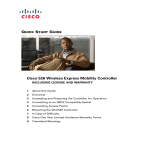
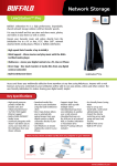
Cisco Smart Business Communications System Setup
Vo
e
ic
D
at
a
Version 1.0
Vi
o
de
M
ob
ili
ty
Small
Business
Partners Start Here
The Smart Choice for Small Business
Small businesses are looking for appropriately priced products and services to meet their growing communications
needs. With the Cisco Smart Business Communications System, you can offer your small-business customers:
• An affordable, complete portfolio of Cisco Unified Communications products that interoperate seamlessly to provide
secure voice, video, mobility, and data networking
• Access to the right mix of key communications, productivity, and business operations applications
This versatile solution can be deployed as an 8-voice user system or 16-voice user system and up to 250 data users with
wireless access. The full system comprises multiple components:
• Cisco Unified Communications 500 Series for Small Business (Cisco Unified Communications 500 Series) — IP telephony
solution that provides an integrated voice messaging system and automated attendant, eight Power-over-Ethernet (PoE)
ports for wired Cisco Unified IP Phone and PC connections, and also provides wireless connectivity through an
integrated wireless access point option. Supports public switched telephone network (PSTN) trunks, IP trunks, and
local analog devices. Enables data, security, and wireless services for up to two teleworkers.
• Cisco Catalyst Express 520 Switch — Enables the system to expand to a 16-voice user system by providing 8 additional
PoE ports for wired and wireless support.
• Cisco Mobility Express Solution
• Cisco 500 Series Wireless Express Access Points —Wireless access points that are available in two modes of
operation : standalone-mode Cisco 521 Wireless Access Points and controller-mode Cisco 521 Wireless Access
Points. The controller-mode access point works only with the Cisco 526 Wireless Express Mobility Controller.
• Cisco 500 Series Wireless Express Mobility Controller— Controls and automatically configures the controllermode access points. Retrieves air-monitoring information from the controller-based access points, analyzes the
information, and takes the appropriate measure for optimum coverage.
• System Management
• Cisco Configuration Assistant —GUI software that simplifies system configuration.
• Cisco Smart Assist Features— By enabling plug-and-play functionality, reduces the time needed to set up the
devices and applications in the network. Helps to optimize the network settings. Some Smart Assist features
include default configuration to allow automatic discovery of supported devices, PBX configuration on the
Cisco Unified Communications 500 Series, firewall activation with a default configuration, auto phone extension
assignments, and password and VLAN synchronization for supported system devices.
• Cisco Monitor Manager and Cisco Monitor Director— GUI software for real-time monitoring of the system.
8^hXd
Bdc^idg
9^gZXidg
8^hXd*'&
L^gZaZhh:megZhh
6XXZhhEd^cih
8ViVanhi:megZhh*'%Hl^iX]
;Vm
8^hXd*'+L^gZaZhh:megZhh
BdW^a^in8dcidaaZg
8^hXd
8dc[^\jgVi^dc
6hh^hiVci$
8^hXdBdc^idg
BVcV\Zg
2
1
>ciZgcZi
EHIC
8^hXdJc^[^ZY
8dbbjc^XVi^dch
*%%HZg^ZhEaVi[dgb
EVgicZg
H^iZ
9HA$8VWaZ
BdYZb
8^hXd
-,%HZg^Zh
GdjiZg
IZaZldg`Zg
H^iZ
230632
Page Installation Checklist
guides you,
as a Cisco
partner,
through the initial installation of the full Smart Business Communications System.
This document
The ease of use and the level of preconfiguration make this system easy to deploy, operate, and manage, while providing
expansion capabilities to support business growth. A typical installation involves some or all of the following activities:
Determining the dial plan settings for deployment: PBX or key operation mode.
• Single-site PBX — PBX mode is set as the default. Most settings are preconfigured, and voice connectivity is
provided through the PSTN. A DSL or cable modem is used for Internet access.
• Single-site key system — Key system square mode and some default settings need to be changed. Voice connectivity
is provided through the PSTN. A DSL or cable modem is used for Internet access.
• Session Initiation Protocol (SIP) Trunk configuration—A service provider supplies connection to the phones.
Determining wireless network options.
• All-in-one architecture — Single integrated access point (factory-installed access point option within the
Cisco Unified Communications 500 Series platform), provides Wi-Fi Protected Access (WPA/WPA2), and multiple
Service Set Identifiers (SSIDs). This single integrated access point cannot be upgraded into a controller-based
architecture. For a broader coverage, two wireless express access points can be deployed in a standalone mode in
addition to the integrated access point.
• Standalone architecture — Up to three wireless express access points can be deployed to offer extended coverage.
• Controller-based architecture — Advanced wireless with up to 12 wireless express access points associated with
Wireless Express Mobility Controllers (up to 6 access points per controller). Provides advanced features such as Radio
Resource Management, secure wireless guest access, and optimized support for voice over Wi-Fi with roaming and
load balancing.
Determining remote monitoring options (Cisco Monitor Manager and Cisco Monitor Director).
• A 30-day evaluation version of Cisco Monitor Manager and Cisco Monitor Director can be downloaded from Cisco.com
at http://www.cisco.com/go/sbnm. The evaluation version of Cisco Monitor Manager can monitor up to 5 network
devices, 5 access points, and 48 Cisco Unified IP Phones. The evaluation version of Cisco Monitor Director can collect
data from up to 5 customers.
Make sure that PC prerequisites are met.
• Cisco Configuration Assistant — Installs on PC with Pentium III–based IBM PC or compatible, 512 MB of DRAM (1 GB
of DRAM is recommended); minimum screen resolution of 1024x768; either Windows XP Service Pack 1 or later, or
Windows 2000 Service Pack 3 or later.
• Cisco Monitor Manager — Installs on PC with 40 GB of available disk space, 1 GB of RAM, Intel Pentium IV (1.2 GHz or
greater) or compatible, and either Windows 2000 Professional Service Pack 4 or Windows XP Professional Service Pack 2.
• Cisco Monitor Director — Installs on PC with 40 GB of available disk space, 2 GB of RAM, Intel Pentium IV (3 GHz or
greater) or compatible. Also required is Windows 2000 Professional Service Pack 4, Windows XP Professional Service
Pack 2, or Windows 2003 Server Service Pack 1, as appropriate.
Refer to the appropriate product documentation for safety information and for the default username and
password of each device that you plan to install.
Collect ISP information and session initiation protocol (SIP) trunk service provider information.
Go to http://www.cisco.com/go/sbcs to download the latest version of this document from Cisco.com.
Perform an initial installation of the full Cisco Smart Business Communications System.
Note: We strongly recommend that you use the factory default settings for the initial installation, whenever possible.
After you verify that the initial installation is working properly, you can use the Cisco Configuration Assistant to easily
change the default settings. Use a Category 5 cable with RJ-45 connections to connect the devices in a Smart
Business Communications System unless specified otherwise.
Page 1
Stage
the UC500
Series
Platform
Configure
the UC500
Series
Platform
8^hXd
8dc[^\jgVi^dc
6hh^hiVci
8^hXdJc^[^ZY8dbbjc^XVi^dch
*%%HZg^ZhEaVi[dgb
>ciZgcZi
E8"&
230633
Note: Throughout the rest of this document, the
terms “UC500” and “CE520” refer to the Cisco Unified
Communications 500 Series platform and the Cisco
Catalyst Express 520 Switch, respectively.
The UC500 can be installed on a desktop or mounted
on a wall or rack. This document describes the desktop
installation (installing the UC500 on a desktop, table, or
shelf). For wall- or rack-mounting instructions, refer to the
documentation for the UC500 platform.
This document assumes that PC-1, the PC that is running
the Cisco Configuration Assistant and that will be used to
perform the initial installation, is connected directly to the
UC500. However, the Cisco Configuration Assistant can be
run on a PC that is connected to the UC500 through a VPN
connection, if desired.
The following are preconfigured:
• Network and device parameters
• Internet connection (DHCP)
• Firewall and Network Address Translation (NAT)
1 Unpack the UC500, place it on a desktop, and power it up.
Note: If you are installing a single-site key system
configuration, change the Voice System Type setting from
PBX to Key System Configuration. This setting is in the
Telephony > Voice > Device Parameters tab.
2 Download a copy of the Cisco Configuration Assistant
from Cisco.com at http://www.cisco.com/go/
configassist.
7 Click OK to save the configuration changes to the
UC500. The system indicates when the configuration is
complete.
3 Install the Cisco Configuration Assistant on PC-1.
Follow the prompts. When the setup is complete, click
Finish.
8 From the Cisco Configuration Assistant, verify that the
UC500 appears in the Topology View window.
4 Launch the Cisco Configuration Assistant by clicking
the desktop icon.
5 Connect PC-1 to one of the PoE ports on the UC500,
as illustrated. Verify that PC-1 is set to obtain its IP
address using DHCP.
Page 6 From the Cisco Configuration Assistant:
• Choose Connect to a new community, and enter a
name for the community.
• In the IP address field, enter 192.168.10.1 and click OK.
• Use the default system administrator username and
password for the UC500.
• Use the default configuration settings for the rest of
the installation.
Tip! Throughout these installation instructions, you
are instructed to verify that the Topology View window
includes the new device. If the Topology View window
does not include the new device, then choose Application
Menu > Refresh to refresh the Topology View window. For
more information about the Cisco Configuration Assistant,
see the online help.
2
Set Up Phone and PC LAN Connections
and WAN Connection
8ViVanhi:megZhh*'%Hl^iX]
E8"&
8^hXd
8dc[^\jgVi^dc
6hh^hiVci
8^hXdJc^[^ZY
8dbbjc^XVi^dch
*%%HZg^Zh
EaVi[dgb
>ciZgcZi
9HA$8VWaZ
BdYZb
230636
Set Up Cisco Phone and PC LAN Connections
Note: The Smart Business Communications System
supports all Cisco Unified IP Phones. Throughout the
rest of this document, the term “Cisco phone” refers to a
“Cisco Unified IP Phone.”
1 Connect PC-1 to one of the PoE ports on the UC500,
as illustrated.
11 Use the wired Cisco phone connections to provide
wired connectivity for end-user PCs. Connect the
Ethernet port on the end-user PC to the 10/100 PC
port on the rear panel of the installed Cisco phone.
Note: You can also use PC-1 to run the Cisco Monitor
Manager, as described on page 9.
Set Up WAN Connection
2 Connect the CE520 uplink port to the UC500
expansion port, as illustrated.
1 At the main site, connect the WAN port on the UC500
to the DSL or cable modem.
3 Connect the AC power cord and power up the CE520.
2 If the ISP requires a WAN configuration other than
DHCP, then you must use the Cisco Configuration
Assistant to change the WAN settings on the UC500.
• From the Cisco Configuration Assistant, in the
Configure > Internet Connection window, choose
Interface FastEthernet0/0, and click Modify.
• If PPPoE, check the PPPoE checkbox, and enter the
username and password provided by the ISP.
• If static IP address, choose Static IP, and enter
the Internet IP address, subnet mask, and default
gateway address.
4 Launch the Cisco Configuration Assistant, and verify
that the installed CE520 appears in the Topology View
window.
5 In the Topology View window, right-click the CE520
icon and choose Add to community.
6 If prompted, use the default system administration
username and password for the CE520.
7 Connect the Cisco phones to the PoE ports on the
UC500 and CE520, as illustrated.
8 From the Cisco Configuration Assistant, verify that the
installed Cisco phones appear in the Topology View
window.
9 Test the extensions by calling another Cisco phone that
is connected to the UC500 or CE520.
Note: The ISP provides all information required in the
WAN Parameters window.
3 From PC-1, test the Internet and WAN link by accessing
an Internet page.
10 Test the PC LAN connection. For example, from PC-1
try to access an intranet page.
Page 3
Set Up PSTN or SIP Trunks
and Teleworker Connections
8^hXd
-,%HZg^Zh
GdjiZg
8ViVanhi:megZhh
*'%Hl^iX]
;Vm
IZaZldg`Zg
H^iZ
EHIC
E8"&
8^hXd
8dc[^\jgVi^dc
6hh^hiVci
8^hXdJc^[^ZY
8dbbjc^XVi^dch
*%%HZg^Zh
EaVi[dgb
>ciZgcZi
9HA$8VWaZ
BdYZb
230634
Set Up for FXO or BRI Lines
Set Up for SIP Trunking
This document describes how to set up a deployment that
uses Foreign Exchange Office (FXO) lines. The UC500 also
has models with Basic-Rate Interface (BRI) ports rather
than FXO ports for deployments that use BRI lines.
For instructions on how to set up a deployment that uses
BRI lines, refer to the documentation for the UC500
platform.
1 From the Cisco Configuration Assistant, set up SIP
trunking.
• In the Topology View window, choose the UC500.
• Click the Telephone > Voice > SIP Trunk
Parameters tab.
• From the drop-down list, choose your SIP Trunk
service provider.
• Enter the fully qualified domain names provided
by the SIP Trunk service provider. Enter the SIP
proxy domain name. Enter the remaining required
information.
• Click OK to save the configuration changes to the
UC500. The system indicates when the configuration
is complete.
1 To connect a PSTN line or a station interface on a
PBX, use an RJ-11 cable to connect an FXO port on the
UC500 to the PSTN or PBX.
2 Use an RJ-11 cable to connect a fax machine to a
Foreign Exchange Station (FXS) port on the UC500,
as illustrated.
3 Using a cell phone, verify outgoing and incoming calls
from the system. When you dial into the UC500 PSTN
numbers, the Auto Attendant picks up the call, and the
voice messaging system greeting is played.
4 At the Auto Attendant prompt, verify the FXS
connections by dialing the fax extension.
Note: All information required in the SIP Parameters
window is provided by the SIP Trunk service provider.
Although the items required vary according to the
specified service provider, the Service Provider and SIP
Proxy fields are mandatory.
Set Up a Teleworker (Optional)
You can utilize a Cisco 870 Series router (for example,
the Cisco 871 router) to set up a teleworker. For more
information on the configuration steps for the Cisco 800
Series router, refer to the Cisco 800 Series documentation,
which can be found at http://www.cisco.com/go/800.
Note: Voice extensions for teleworkers are typically
deployed as part of a PBX system rather than a key system.
Page 4
Deploy Integrated or Standalone Wireless
Access Points
6
8^hXdJc^[^ZY
L^gZaZhh>EE]dcZh
7
8^hXdJc^[^ZYL^gZaZhh>EE]dcZh
8^hXdJc^[^ZY
8dbbjc^XVi^dch
*%%HZg^ZhEaVi[dgb
l^i]^ciZ\gViZYl^gZaZhh
VXXZhhed^ci
E8"&
8^hXd
8dc[^\jgVi^dc
6hh^hiVci
8^hXd*'&L^gZaZhh
:megZhh6XXZhhEd^cih
8^hXd
8dc[^\jgVi^dc
6hh^hiVci
E8"&
8ViVanhi:megZhh
*'%Hl^iX]
8^hXdJc^[^ZY8dbbjc^XVi^dch
*%%HZg^ZhEaVi[dgb
230637
Cisco Smart Business Communications System
with Wireless Access
You can provide wireless access to the Cisco Smart
Business Communications System in two ways:
• Use a single integrated wireless access point for a
small coverage area. No additional network hardware
is needed for voice and data wireless connectivity.
For broader coverage, you can deploy two wireless
express access points in a standalone mode in addition
to the integrated access point.
• Use the Cisco Mobility Express Solution in a standalone
or controller-based architecture.
A. Deploy a Single Integrated Wireless Access Point
1 Connect the swivel-mount dipole antenna to the UC500.
2 From the Cisco Configuration Assistant, choose
Configure > Wireless > Secure Wireless, and
configure the options in the Secure Wireless window.
B. Deploy Cisco Mobility Express Solution in
Standalone Mode
In the standalone architecture, you can deploy up to three
Cisco 500 Series Wireless Access Points and configure
them through the Cisco Configuration Assistant.
1 Verify that a DHCP server is operating on the network.
You can use the DHCP server features of the UC500.
2 Determine which of the available PoE ports on the
CE520 is to be used to connect the first AP521.
From the Cisco Configuration Assistant, change the
port role of the designated port to Access Point:
• In the Topology View window, choose the CE520.
• Choose Configure > Smartports. In the displayed
Smartports window, assign the designated port a
port role of Access Point.
3 Connect the AP521 to the designated port that you just
assigned a port role of Access Point.
4 In the Topology View window, right-click the AP521
icon, and choose Add to community to add the
AP521 to the community. Use the default system
administration username and password for the AP521.
5 From the Cisco Configuration Assistant, choose
Configure > Wireless > Secure Wireless, and
configure the options in the Secure Wireless window.
To enable the radio on a standalone access point, you
must create an SSID and save the configuration. After
the radio is enabled, clients that have the same SSID
as the access point will be associated with that access
point and pass traffic.
6 Repeat Step 2 through Step 5 for each AP521.
Note: The Cisco Mobility Express Solution can be
deployed without the UC500 for customers who want
to immediately use wireless connectivity for their data
network, complete with wired and wireless security, and
who want to add voice in the future. For information about
this type of deployment, refer to the documentation for
the Cisco Wireless Express Mobility Controllers.
Page 5
Deploy Controller-Based Wireless
8
8^hXd*'&
L^gZaZhh:megZhh
6XXZhhEd^cih
8ViVanhi:megZhh*'%Hl^iX]
;Vm
8^hXd*'+L^gZaZhh:megZhh
BdW^a^in8dcidaaZg
2
1
>ciZgcZi
EHIC
8^hXd
8dc[^\jgVi^dc
6hh^hiVci
E8"&
8^hXdJc^[^ZY
8dbbjc^XVi^dch
*%%HZg^ZhEaVi[dgb
9HA$8VWaZ
BdYZb
8^hXd
-,%HZg^Zh
GdjiZg
IZaZldg`Zg
H^iZ
230631
C. Deploy Cisco Mobility Express Solution in
Controller Mode
When the advanced features and controller-mode
access points are needed, deploy the controller-based
architecture. In the controller-based architecture, you can
deploy up to two controllers and 12 access points
(six Cisco 521 Wireless Express Access Points per
controller). If desired, you can deploy the two controllers
in redundant mode.
1 Verify that a DHCP server is operating on the network.
You can use the DHCP server features of the UC500.
2 Power up the Cisco 526 Wireless Express Mobility
controller (WLC526).
3 Connect PC-1 to the controller management port
(port 1) of the WLC526.
4 From PC-1, start Internet Explorer and browse to
http://192.168.1.1. The Startup Wizard launches. Follow
the prompts to configure the WLC526. When you save
your settings, the WLC526 restarts.
5 Start Internet Explorer again, enter the new IP address
of the management port, obtained in Step 4, for the
WLC526, and verify that the WLC526 is accessible.
6 Power off the WLC526, and disconnect PC-1 from the
WLC526. Reconnect PC-1 to a PoE port on the UC500,
and launch the Cisco Configuration Assistant.
7 Determine which of the available PoE ports on the
CE520 is to be used to connect the WLC526.
From the Cisco Configuration Assistant, change the
port role of the designated port to Access Point:
• In the Topology View window, choose the CE520.
• Choose Configure > Smartports. In the Smartports
window, assign the designated port a port role of
Access Point.
8 Connect the WLC526 to the designated port that you
just assigned a port role of Access Point.
9 In the Topology View window, right-click the WLC526
icon, and choose Add to community to add the
WLC526 to the community. Use the default system
administration username and password for the WLC526.
10 From the Cisco Configuration Assistant, choose Configure
> Wireless > Secure Wireless, and configure the
options in the Secure Wireless window for the WLC526.
11 On the CE520, install up to six access points:
• Determine which of the available PoE ports on the
CE520 is to be used to connect a Cisco 521 Wireless
Express Access Point. From the Cisco Configuration
Assistant, change the port role of the designated port
to Access Point:
• In the Topology View window, choose the CE520.
• Choose Configure > Smartports. In the Smartports
window, assign the designated port a port role of
Access Point.
• Connect the Cisco 521 Wireless Express Access
Point to the designated port that you just assigned a
port role of Access Point.
The WLC526 configures the access points automatically.
Page 6
Deploy Remote Monitoring
8^hXd
Bdc^idg
9^gZXidg
8^hXd*'&
L^gZaZhh:megZhh
6XXZhhEd^cih
8ViVanhi:megZhh*'%Hl^iX]
;Vm
8^hXd*'+L^gZaZhh:megZhh
BdW^a^in8dcidaaZg
8^hXd
8dc[^\jgVi^dc
6hh^hiVci$
8^hXdBdc^idg
BVcV\Zg
2
E8"'
1
>ciZgcZi
EHIC
E8"&
EVgicZg
H^iZ
8^hXdJc^[^ZY
8dbbjc^XVi^dch
*%%HZg^ZhEaVi[dgb
9HA$8VWaZ
BdYZb
8^hXd
-,%HZg^Zh
GdjiZg
IZaZldg`Zg
H^iZ
230635
Install Cisco Monitor Manager
1 At the main site, install and launch the Cisco Monitor
Manager evaluation software on PC-1.
• Download a copy of the software from Cisco.com at
http://www.cisco.com/go/sbnm.
• Double-click CiscoMMInstaller.exe to start the
installation.
• Follow the prompts to install and launch the software.
• Choose the evaluation version, and click OK.
Create a user by entering a user ID, password, and
customer name. Click OK. The Discover Devices
window opens.
2 Click Create to open the Create New Location dialog
box. Enter the name and description of a new device
location and then click OK.
3 Verify that the Cisco Monitor Manager is operating
properly.
• In the Specify a Seed IP Address field, enter the
IP address of the UC500, and click Start.
• If prompted, enter the username and password of
the UC500.
• Choose the UC500 in the device table, and click OK.
Install Cisco Monitor Director
1 At your site, make sure that PC-2 can be reached
through the Internet on TCP port 443.
2 Install and launch the Cisco Monitor Director evaluation
software on PC-2.
• Download a copy of the software from Cisco.com at
http://www.cisco.com/go/sbnm.
• Double-click CiscoMDInstaller.exe to start the
installation.
• Follow the prompts to install and launch the software.
• Choose the evaluation version, and click OK. You are
prompted to create a customer account. Enter the
appropriate information in the Add Customer dialog
box, and click OK. The customer should be one at
which the Cisco Monitor Manager is installed.
Verify Communication Between Cisco Monitor Manager
and Cisco Monitor Director
Note: If you are using Windows XP, and Windows Firewall
is enabled, open the port that is used for HTTPS through
the firewall so that the Cisco Monitor Manager and the
Cisco Monitor Director can communicate.
1 From the Cisco Monitor Manager, in the
Administration > Options > Cisco Monitor Director
window, enter information for your Cisco Monitor Director
software. Check the Enable Communication with Cisco
Monitor Director checkbox. Click Test. Make sure that a
solid green dot appears in the Windows system tray.
2 From the Cisco Monitor Director, in the Customer Network
Status window, make sure that a solid green circle
appears in the MM-MD Status field for the customer.
For additional information, see the online help for the
Cisco Monitor Manager and the Cisco Monitor Director.
Page Post-Installation Checklist
After you install the Cisco Smart Business Communications System, perform the following activities as needed.
Use the Cisco Configuration Assistant to change the default settings.
• In Configure > Device Properties > Users and Passwords, change the default username and password for all
the devices.
• In Configure > Device Properties > Hostname, change the default hostname for each device.
• In Configure > Device Properties > System Time, set the system time zone, time display, and the NTP servers
for the UC500.
• To access the voice system configuration tabs for the UC500, launch Configure > Telephony > Voice.
• In the Device Parameters tab, designate the system message. This message appears on the Cisco Unified IP
Phone screens. For example, change the system message to the customer business name.
• In the Dial Plan/Voice Mail tab, set the number of digits for each Cisco phone extension.
• In the Voice System Features tab, configure Cisco phone features and intercom.
• Configure extensions in the User Parameters tab, or build a comma-separated value (.csv) file with names and
extension numbers to import into the Cisco Configuraton Assistant.
• In the Network Parameters tab, configure network settings for voice.
Note: You perform the above tasks from PC-1, the PC that is running the Cisco Configuration Assistant.
For more information about the Cisco Configuration Assistant, see the online help.
Perform remote monitoring activities.
• Inform your customer that the Cisco Monitor Manager has been installed at the customer’s main site. Then show the
customer how to use the Cisco Monitor Manager.
• Decide whether you want to use the Cisco Monitor Director to generate subscription-based reports for your
customers. If yes, generate a Network Summary Report, Performance Summary Report, and Monthly Summary
Report to demonstrate the value of these subscription-based reports.
Enable your customers to make future configuration changes.
If you want your customer to be able to use the Cisco Configuration Assistant to make future configuration changes
themselves (for example, by adding another Cisco Unified IP Phone), then inform your customers that you have installed
the Cisco Configuration Assistant on PC-1 and that they can use the Cisco Configuration Assistant for future configuration
changes.
Page 10
?
Where to Go from Here
Cisco provides a wide range of resources to help you and your customer obtain the full benefits of the Cisco Smart
Business Communications System.
The Cisco Smart Business Communications System
website provides information and references pertaining to
the system, including links to the full documentation set for
each component.
http://www.cisco.com/go/sbcs
The Cisco Partners website provides access to a variety of
information and tools for Cisco partners.
http://www.cisco.com/web/partners/index.html
The Cisco Support website provides online documents and
tools for troubleshooting and resolving technical issues with
Cisco products and technologies.
http://www.cisco.com/en/US/support/index.html
Cisco Marketplace provides a variety of Cisco books,
reference guides, and documentation.
http://www.cisco.com/go/marketplace/
Cisco Press publishes a wide range of general networking,
training, and certification documents.
http://www.ciscopress.com
Page 11
Corporate Headquarters
Cisco Systems, Inc.
170 West Tasman Drive
San Jose, CA 95134-1706
USA
www.cisco.com
Tel: 408 526-4000
800 553-NETS (6387)
Fax: 408 526-4100
European Headquarters
Cisco Systems International BV
Haarlerbergpark
Haarlerbergweg 13-19
1101 CH Amsterdam
The Netherlands
www-europe.cisco.com
Tel: 31 0 20 357 1000
Fax: 31 0 20 357 1100
Americas Headquarters
Cisco Systems, Inc.
170 West Tasman Drive
San Jose, CA 95134-1706
USA
www.cisco.com
Tel: 408 526-7660
Fax: 408 527-0883
Asia Pacific Headquarters
Cisco Systems, Inc.
168 Robinson Road
#28-01 Capital Tower
Singapore 068912
www.cisco.com
Tel: +65 6317 7777
Fax: +65 6317 7799
Cisco Systems has more than 200 offices in the following countries and regions. Addresses, phone numbers, and fax numbers are listed on the
Cisco.com Website at www.cisco.com/go/offices.
Argentina • Australia • Austria • Belgium • Brazil • Bulgaria • Canada • Chile • China PRC • Colombia • Costa Rica • Croatia • Cyprus • Czech Republic
Denmark • Dubai, UAE • Finland • France • Germany • Greece • Hong Kong SAR • Hungary • India • Indonesia • Ireland • Israel • Italy
Japan • Korea • Luxembourg • Malaysia • Mexico • The Netherlands • New Zealand • Norway • Peru • Philippines • Poland • Portugal
Puerto Rico • Romania • Russia • Saudi Arabia • Scotland • Singapore • Slovakia • Slovenia • South Africa • Spain • Sweden
Switzerland • Taiwan • Thailand • Turkey • Ukraine • United Kingdom • United States • Venezuela • Vietnam • Zimbabwe
Copyright © 2006 Cisco Systems, Inc. All rights reserved. CCSP, CCVP, the Cisco Square Bridge logo, Follow Me Browsing, and StackWise are trademarks of Cisco Systems, Inc.; Changing the Way We Work,
Copyright © 2007 Cisco Systems, Inc. All rights reserved. CCVP, the Cisco Logo, and the Cisco Square Bridge logo are trademarks of Cisco Systems, Inc.; Changing the Way We
Live, Play, and Learn, and iQuick Study are service marks of Cisco Systems, Inc.; and Access Registrar, Aironet, BPX, Catalyst, CCDA, CCDP, CCIE, CCIP, CCNA, CCNP, Cisco, the Cisco Certified Internetwork
Work,logo,
Live,Cisco
Play,
and
Learn
is Cisco
a service
mark
of Cisco
Inc;
and
Access
Registrar,
Aironet,
BPX, Catalyst,
CCDA,EtherFast,
CCDP, EtherSwitch,
CCIE, CCIP,
CCNA,
CCNP, CCSP,
Cisco,
the
Expert
IOS,
Cisco
Press,
Systems,
Cisco
SystemsSystems,
Capital, the
Cisco
Systems
logo,
Cisco Unity,
Enterprise/Solver,
EtherChannel,
Fast
Step, FormShare,
GigaDrive,
GigaStack,
HomeLink,
Internet
Quotient, IOS,Expert
IP/TV, iQ
Expertise,
iQ logo,
iQPress,
Net Readiness
Scorecard, LightStream,
Linksys,
MeetingPlace,
MGX,
the Networkers
logo,Unity,
Networking
Academy, Network
Registrar, Packet,
Cisco Certified
Internetwork
logo,
Ciscothe
IOS,
Cisco
Cisco Systems,
Cisco Systems
Capital,
the Cisco
Systems
logo, Cisco
Enterprise/Solver,
EtherChannel,
PIX,
Post-Routing,
Pre-Routing,
ProConnect,
RateMUX,
ScriptShare,
ScriptShare,
SlideCast,
SMARTnet,
The
Fastest
Way
to
Increase
Your
Internet
Quotient,
and
TransPath
are
registered
trademarks
of
Cisco
EtherFast, EtherSwitch, Fast Step, Follow Me Browsing, FormShare, GigaDrive, GigaStack, HomeLink, Internet Quotient, IOS, iPhone, IP/TV, iQ Expertise, the iQ logo, iQ Net
Systems, Inc. and/or its affiliates in the United States and certain other countries.
Readiness Scorecard, iQuick Study, LightStream, Linksys, MeetingPlace, MGX, Networking Academy, Network Registrar, Packet, PIX, ProConnect, RateMUX, ScriptShare,
SlideCast,
SMARTnet,
StackWise,
The Fastest
Wayare
tothe
Increase
Internet
Quotient,
and use
TransPath
arepartner
registered
trademarks
of Ciscorelationship
Systems, between
Inc. and/or
the
All
other trademarks
mentioned
in this document
or Website
propertyYour
of their
respective
owners. The
of the word
does not
imply a partnership
Ciscoits
andaffiliates
any otherin
company.
(0601R)
United States and certain other countries.
All other trademarks mentioned in this document or Website are the property of their respective owners. The use of the word partner does not imply a partnership relationship
between Cisco and any other company. (0612R)
78-18062-01