1
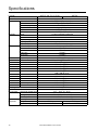
User Manual Rack LCD Console AP5717, AP5717CH, AP5717F, AP5717G, AP5717J, AP5717R, AP5717UK, AP5719 990-3863-001 Publication Date: October, 2013 Schneider Electric IT Corporation Legal Disclaimer The information presented in this manual is not warranted by the Schneider Electric IT Corporation to be authoritative, error free, or complete. This publication is not meant to be a substitute for a detailed operational and site specific development plan. Therefore, Schneider Electric IT Corporation assumes no liability for damages, violations of codes, improper installation, system failures, or any other problems that could arise based on the use of this Publication. The information contained in this Publication is provided as is and has been prepared solely for the purpose of evaluating data center design and construction. This Publication has been compiled in good faith by Schneider Electric IT Corporation. However, no representation is made or warranty given, either express or implied, as to the completeness or accuracy of the information this Publication contains. IN NO EVENT SHALL SCHNEIDER ELECTRIC IT CORPORATION, OR ANY PARENT, AFFILIATE OR SUBSIDIARY COMPANY OF SCHNEIDER ELECTRIC IT CORPORATION OR THEIR RESPECTIVE OFFICERS, DIRECTORS, OR EMPLOYEES BE LIABLE FOR ANY DIRECT, INDIRECT, CONSEQUENTIAL, PUNITIVE, SPECIAL, OR INCIDENTAL DAMAGES (INCLUDING, WITHOUT LIMITATION, DAMAGES FOR LOSS OF BUSINESS, CONTRACT, REVENUE, DATA, INFORMATION, OR BUSINESS INTERRUPTION) RESULTING FROM, ARISING OUT, OR IN CONNECTION WITH THE USE OF, OR INABILITY TO USE THIS PUBLICATION OR THE CONTENT, EVEN IF SCHNEIDER ELECTRIC IT CORPORATION HAS BEEN EXPRESSLY ADVISED OF THE POSSIBILITY OF SUCH DAMAGES. SCHNEIDER ELECTRIC IT CORPORATION RESERVES THE RIGHT TO MAKE CHANGES OR UPDATES WITH RESPECT TO OR IN THE CONTENT OF THE PUBLICATION OR THE FORMAT THEREOF AT ANY TIME WITHOUT NOTICE. Copyright, intellectual, and all other proprietary rights in the content (including but not limited to software, audio, video, text, and photographs) rests with Schneider Electric It Corporation or its licensors. All rights in the content not expressly granted herein are reserved. No rights of any kind are licensed or assigned or shall otherwise pass to persons accessing this information. This Publication shall not be for resale in whole or in part. Contents General Information................................................................... 1 Overview . . . . . . . . . . . . . . . . . . . . . . . . . . . . . . . . . . . . . . . . . . . . . . . . . . . .1 Important Safety Information . . . . . . . . . . . . . . . . . . . . . . . . . . . . . . . . . . .1 Related Documents . . . . . . . . . . . . . . . . . . . . . . . . . . . . . . . . . . . . . . . . . . .1 User Comments . . . . . . . . . . . . . . . . . . . . . . . . . . . . . . . . . . . . . . . . . . . . . .1 Safety............................................................................................. 2 SAVE THESE INSTRUCTIONS! . . . . . . . . . . . . . . . . . . . . . . . . . . . . . . . . 2 Regulatory agency approval . . . . . . . . . . . . . . . . . . . . . . . . . . . . . . . . . . 2 Additional Safety Information . . . . . . . . . . . . . . . . . . . . . . . . . . . . . . . . . . .3 Before you begin . . . . . . . . . . . . . . . . . . . . . . . . . . . . . . . . . . . . . . . . . . . . 3 Operation and Adjustments . . . . . . . . . . . . . . . . . . . . . . . . . . . . . . . . . . . 3 Taking Delivery. . . . . . . . . . . . . . . . . . . . . . . . . . . . . . . . . . . . . . . . . . . . . . .3 Inventory . . . . . . . . . . . . . . . . . . . . . . . . . . . . . . . . . . . . . . . . . . . . . . . . . . . 3 Components . . . . . . . . . . . . . . . . . . . . . . . . . . . . . . . . . . . . . . . . . . . . . . . . .4 Front View . . . . . . . . . . . . . . . . . . . . . . . . . . . . . . . . . . . . . . . . . . . . . . . . . . 4 Rear View . . . . . . . . . . . . . . . . . . . . . . . . . . . . . . . . . . . . . . . . . . . . . . . . . . 6 ...........................................................6 Installation .................................................................................... 7 Brackets . . . . . . . . . . . . . . . . . . . . . . . . . . . . . . . . . . . . . . . . . . . . . . . . . . . .7 Rack LCD Console Installation. . . . . . . . . . . . . . . . . . . . . . . . . . . . . . . . . .8 Cable installation . . . . . . . . . . . . . . . . . . . . . . . . . . . . . . . . . . . . . . . . . . . . 8 Power On the Rack LCD Console . . . . . . . . . . . . . . . . . . . . . . . . . . . . . . 8 User Manual Rack LCD Console 1 Operation ..................................................................................... 9 Basic Functions . . . . . . . . . . . . . . . . . . . . . . . . . . . . . . . . . . . . . . . . . . . . . .9 Opening the Rack LCD Console . . . . . . . . . . . . . . . . . . . . . . . . . . . . . . . 9 Closing the Rack LCD Console . . . . . . . . . . . . . . . . . . . . . . . . . . . . . . . . 9 Powering off and restarting . . . . . . . . . . . . . . . . . . . . . . . . . . . . . . . . . . . 9 Standby mode . . . . . . . . . . . . . . . . . . . . . . . . . . . . . . . . . . . . . . . . . . . . . . 9 Hot plugging . . . . . . . . . . . . . . . . . . . . . . . . . . . . . . . . . . . . . . . . . . . . . . . 9 LCD OSD (On Screen Display) configuration . . . . . . . . . . . . . . . . . . . 10 Monitor settings . . . . . . . . . . . . . . . . . . . . . . . . . . . . . . . . . . . . . . . . . . . . 10 USB Peripheral Devices . . . . . . . . . . . . . . . . . . . . . . . . . . . . . . . . . . . . . 10 Firmware Upgrade Mode . . . . . . . . . . . . . . . . . . . . . . . . . . . . . . . . . . . . .11 Start the upgrade . . . . . . . . . . . . . . . . . . . . . . . . . . . . . . . . . . . . . . . . . . 11 Upgrade succeeded . . . . . . . . . . . . . . . . . . . . . . . . . . . . . . . . . . . . . . . . 11 Upgrade failed . . . . . . . . . . . . . . . . . . . . . . . . . . . . . . . . . . . . . . . . . . . . . 11 Exit firmware upgrade mode . . . . . . . . . . . . . . . . . . . . . . . . . . . . . . . . . 12 Firmware upgrade recovery . . . . . . . . . . . . . . . . . . . . . . . . . . . . . . . . . 12 Troubleshooting ....................................................................... 13 Specifications............................................................................ 14 2 User Manual Rack LCD Console General Information Overview The Rack LCD Console features a 17” or a 19” LCD panel, a full keyboard, and a touch pad in a rack-mountable sliding housing. The Rack LCD Console is intended for use with compatible target devices (a KVM switch or server). Important Safety Information Read the instructions carefully to become familiar with the device before trying to install, operate, service or maintain it. The following messages may appear throughout this manual or on the equipment to warn of potential hazards or to call attention to information that clarifies or simplifies a procedure. The addition of this symbol to a Danger or Warning safety label indicates that an electrical hazard exists which will result in personal injury if the instructions are not followed. This is the safety alert symbol. It is used to alert you to potential personal injury hazards. Obey all safety messages that follow this symbol to avoid possible injury or death. DANGER DANGER indicates an imminently hazardous situation which, if not avoided, will result in death or serious injury. WARNING WARNING indicates a potentially hazardous situation which, if not avoided, can result in death or serious injury. CAUTION CAUTION indicates a potentially hazardous situation which, if not avoided, can result in minor or moderate injury. CAUTION CAUTION, used without the safety alert symbol, indicates a potentially hazardous situation which, if not avoided, can result in equipment damage. NOTICE NOTICE addresses practices not related to physical injury including certain environmental hazards, potential damage or loss of data. Related Documents Download technical publications or look for updates to your manual at www.apc.com. User Comments Contact www.apc.com/support. We welcome your comments about this document. User Manual Rack LCD Console 1 Safety SAVE THESE INSTRUCTIONS! This manual contains important instructions that must be followed during installation, operation, and maintenance of the device. DANGER HAZARD OF ELECTRIC SHOCK, EXPLOSION, OR ARC FLASH • Consult your power company if you are unsure if your power source is compatible with the device requirements.. • The device is designed to use with IT power distribution systems with up to 230V phase-tophase voltage. • Do not overload the AC branch circuit that provides power to the rack. • To prevent damage, make sure all devices are properly grounded. • The device is equipped with a 3-wire grounding type plug. Have an electrician update your outlet if the plug does not fit. Do not attempt to defeat the grounding plug. • Do not exceed the total ampere rating of extension cords if used. Make sure extension cords or power strips are properly grounded. • Protect the system from sudden changes in electrical power with a surge suppressor or uninterruptible power supply (UPS). Failure to follow these instructions will result in death or serious injury. CAUTION HAZARDS RESULTING FROM MISUSE • Route the power cord and cables so they cannot be stepped on or tripped over. • Avoid injury and equipment damage as a result of rack failure. Read and adhere to the installation and safety instructions that accompany your racks • Never lean on the device. • Slide rail mounted equipment is not to be used as a shelf or a work space. Do not set objects on the device. • Serious damage will result if the device is dropped or falls. • Do not block ventilation openings. The Rack LCD Console requires proper air flow for safe operation. • Do not place the device near or over radiators or heat registers. • The rack ambient temperature should be not greater than 104°F (40°C). • Do not use the device near water. Do not spill any liquid on the device. • Do not use liquid or aerosol cleaners. Clean the device with a damp cloth. • Use only the hardware provided to install the Rack LCD Console in the rack. Failure to follow these instructions can result in injury or equipment damage. Regulatory agency approval This equipment has been tested and found to comply with the limits for a class A digital device, pursuant to part 15 of the FCC Rules. These limits are designed to provide reasonable protection against harmful interference when the equipment is operated in a commercial environment. This equipment generates, uses, and can radiate radio frequency energy and, if not installed and used in accordance with the installation guide, may cause harmful interference to radio communications. Operation of this equipment in a residential area is likely to cause harmful interference, in which case the user will be required to correct the interference at his own expense. 2 User Manual Rack LCD Console Additional Safety Information Before you begin Verify that the system is free from all short circuits and grounds, except those grounds installed according to local regulations (according to the National Electrical Code in the U.S.A., for instance). If high-potential voltage testing is necessary, follow recommendations in equipment documentation to prevent accidental equipment damage. Before energizing equipment: • Remove tools, meters, and debris from equipment. • Close the equipment enclosure door. • Perform all start-up tests recommended by the manufacturer. Operation and Adjustments The following precautions are from the NEMA Standards Publication ICS 7.1-195 (English version prevails): • Regardless of the care exercised in the design and manufacture of equipment or in the selection and ratings of components, there are hazards that can be encountered if such equipment is improperly operated. • It is sometimes possible to misadjust the equipment and thus produce unsatisfactory or unsafe operation. Always use the manufacturer’s instructions as a guide for functional adjustments. Personnel who have access to these adjustments should be familiar with the equipment manufacturer's instructions and the machinery used with the electrical equipment. • Only those operational adjustments actually required by the operator should be accessible to the operator. Access to other controls should be restricted to prevent unauthorized changes in operating characteristics. Taking Delivery Examine the components at the time of delivery to be sure all parts are present and in good working order. Anything missing or damaged must be reported immediately to the shipping firm and to Schneider Electric. Inventory Description Quantity Easy installation rack mounting installation kit 1 Mounting screws 4 Custom communication cable sets - USB cable, length 6 ft. (1) - PS2 cable, length 6 ft. (1) 2 C13 - C14 power cord 1 NEMA 5 - 15 power cord 1 Firmware upgrade cable 1 USB cable 1 Rack LCD Console 1 Literature Kit Includes: - CD (contains User Manual) - Quick Start Guide - China ROHS 1 User Manual Rack LCD Console 3 Components Front View EXIT MENU LCD POWER UPGRADE FW UPGRADE NUM LOCK 4 CAPS LOCK SCROLL LOCK RESET User Manual Rack LCD Console aem0351b Stand by Item Number Component Description EXIT button 1. Pressing the EXIT button without opening the On Screen Display (OSD) initiates an auto adjustment which reconfigures all settings for the monitor to the optimum display values of the OSD. 2. While the OSD user interface is in use, press the EXIT button to exit the current menu and return to the previous menu or, press the EXIT button to leave an adjustment menu when the adjustment is complete. 3. From the Main Menu screen, pressing the EXIT button, will exit the OSD. Left/Down Arrows button Pressing this button moves left or down through the menu and decreases the value when making an adjustment. Right/Up Arrows button Pressing this button moves right or up through the menu and increases the value when making an adjustment. MENU button 1. If the OSD user interface has not been opened, pressing the MENU button initiates it and brings up the Main menu. 2. While the OSD user interface is in use, when a setting choice is reached, pressing the MENU button brings up the setting’s adjustment screen. LCD POWER button Turns on power to the LCD monitor. An LED light next to the switch will illuminate when the monitor is in stand-by (power-saver) mode. UPGRADE port An RJ-11 port to be used to transfer firmware upgrades from the administrator’s server to the Rack LCD Console. FW UPGRADE The Firmware Upgrade switch should be in the NORMAL position NORMAL / RECOVERY during normal operation of the Rack LCD Console. The switch is set to RECOVERY only when a Firmware Upgrade Recovery is performed. (See “Firmware upgrade recovery” on page 12 for more information.) LCD monitor The LCD display monitor of the Rack LCD Console. RESET switch Press this recessed switch in with a small object (a pen point) to perform a system reset. SCROLL LOCK LED When illuminated, the SCROLL LOCK LED indicates the scroll lock function on the keyboard is enabled. CAPS LOCK LED When illuminated, the CAPS LOCK LED indicates the capitals lock function on the keyboard is enabled. NUM LOCK LED When illuminated, the NUM LOCK LED indicates the number lock function on the keyboard is enabled. USB port Located on the front of the Rack LCD Console, the USB port is used to connect a peripheral device (flash drive, CD-ROM drive, or mouse) and pass through the Rack LCD Console to the connected target device (a KVM switch or server). User Manual Rack LCD Console 5 Rear View 1 PS/2 - USB CPU aem0351a 0 POWER Item Number Component Description Power Socket Standard 3-prong AC power socket. Power Switch Standard ON/OFF rocker switch Custom Port for connecting the Rack LCD Console to the target device (KVM Communication Port switch or server) using one of the included custom communication cables (PS2 or USB). USB Port USB pass-through from the USB Port on the front of the Rack LCD Console. 6 User Manual Rack LCD Console Installation Brackets Use only the hardware provided to install the Rack LCD Console in the rack. 1. Attach the left and right mounting rails to the inside of the rack. The flange that supports the Rack LCD Console station will be to the inside. a. Screw the front flanges to the rack first. na0347a 2. Slide the bars with the rear flanges toward the rack until the flanges make contact with the rack then screw the rear flanges to the rack. 3. Slide the Rack LCD Console () onto the support flanges (). Use the M4 x 6 screws () supplied to loosely attach the front of the Rack LCD Console to the front of the rack. a. Do not fully tighten the screws at this time. User Manual Rack LCD Console 7 4. Slide the rear attachment sliding brackets along the slide bars until they contact the rear of the Rack LCD Console. Use the supplied M4 x 6 screws to attach the bars to the rear of the Rack LCD Console switch. Fully tighten these screws. 6. If the Rack LCD Console is moving properly in the brackets, fully tighten the screws inserted in step 3. aem0348a 5. Slide the Rack LCD Console open and closed two or three times to be sure it is operating smoothly. Rack LCD Console Installation Cable installation Connect the target device (KVM switch or server) to the custom communication port on the back of the Rack LCD Console using one of the two custom communication cables (PS2 or USB) that are included. Plug the keyboard, monitor, and mouse connectors to the ports on the target device (KVM switch or server). Note: The maximum distance between the Rack LCD Console and the target device (a KVM switch or server) is 32.8 feet (10m). Power On the Rack LCD Console 1. Plug the power cord into the power socket on the Rack LCD Console and into an AC power outlet. 2. Turn the Rack LCD Console on. See “Power Switch” on page 6 for the location of the On/Off toggle switch at the back of the Rack LCD Console. 8 User Manual Rack LCD Console Operation Basic Functions Opening the Rack LCD Console CAUTION HAZARDS RESULTING FROM MISUSE • Never lean on the device. • Slide rail mounted equipment is not to be used as a shelf or a work space. Do not set objects on the device. Failure to follow these instructions can result in injury or equipment damage. To access the console, slide the Rack LCD Console out of the rack and raise the cover. Closing the Rack LCD Console Close the cover and slide the Rack LCD Console into the rack. Powering off and restarting Turn off the power to the Rack LCD using the rear panel power switch. See “Power Switch” on page 6 for the location of the On/Off switch. To restart the Rack LCD turn the rear panel power switch back on. Standby mode The Rack LCD will go into Standby mode to save energy when the cover is closed. The display will turn OFF when the cover reaches approximately 15 degrees from completely closed. Power will remain ON but the monitor display will be OFF. Hot plugging Components can be removed and added to the Rack LCD Console by unplugging their cables from the ports without the need to shut down the console. User Manual Rack LCD Console 9 LCD OSD (On Screen Display) configuration Button Function MENU 1. Starting: Pressing the MENU button initiates the LCD OSD and brings up the Main menu. 2. While the OSD user interface is in use, when a setting choice is reached, pressing the MENU button brings up the setting adjustment window. Right/Up Arrow Button Clicking the Right/Up Arrow button moves the cursor Right or Up through the menus, or increases the value when making an adjustment. Left/Down Arrow Button Clicking the Left/Down Arrow button moves the cursor Left or Down through the menus, or decreases the value when making an adjustment. EXIT 1. If the LCD OSD user interface has not been started, pressing the EXIT button initiates an auto adjustment which reconfigures the settings to the display defaults. 2. While the LCD OSD is in use, pressing the EXIT button will exit the current menu and return to the previous menu. To leave an adjustment menu, press the EXIT button when the adjustment is complete. 3. From the Main Menu screen, pressing the EXIT button, will exit the LCD OSD. Monitor settings Setting Explanation Brightness Adjust the brightness level of the screen. Contrast Adjust level of color difference between foreground and background colors. Phase Adjust the phase setting of the screen so that no dark horizontal bands are visible. Clock Adjust the clock setting of the screen so that no dark vertical bands are visible. H-Position Moves the display area left or right. V-Position Moves the display area up or down. Color Hue Adjusts the color quality of the display. The Adjust Color selection has a submenu that allows fine tuning of RGB values. Language Select the language in which the OSD displays menus. OSD Duration Adjust the number of seconds before the On Screen Display shuts down due to inactivity. Reset Resets all menus (except language) and submenus to factory default settings. Note: See “EXIT” on page 10 for information on setting the auto-adjust feature. USB Peripheral Devices The front panel USB port is available to connect a USB peripheral device (flash drive, CD-ROM drive, mouse, etc.) to the target device (KVM switch or server) using the pass-through USB port on the back of the Rack LCD Console. The front panel USB port will recognize a USB peripheral device when it is inserted. If a mouse is subsequently used in that port, use the hotkey combination Ctrl + Enter to reset the port so it will recognize the mouse. 10 User Manual Rack LCD Console Firmware Upgrade Mode Check www.apc.com regularly to find the latest information and firmware upgrade packages. Note: Do not connect the RJ-11 port marked “Upgrade” to a public telecommunication network. Start the upgrade To download the firmware upgrade package: 1. Turn off the power to the Rack LCD Console. 2. Slide the Firmware switch to RECOVER. 3. Turn on the power to the Rack LCD Console. Note: When the Rack LCD Console is in Firmware Upgrade Mode, the Num Lock, Caps Lock and Scroll Lock LEDs will flash on and off repeatedly. 4. Connect the Firmware Upgrade Cable (provided) to a COM port on a computer that is not part of your installation and to the Firmware Upgrade Port of the Rack LCD Console. From your computer, go to www.apc.com and enter the model name of your Rack LCD Console for a list of available firmware upgrade packages. 5. Run the download from your computer by double clicking the file icon, or by opening a command line and entering the full path and filename. 6. The Firmware Upgrade Utility Welcome screen will appear. 7. Read and agree to the License Agreement by clicking the I Agree button. 8. The Firmware Upgrade Utility main screen will appear. The Utility inspects your installation. All devices capable of being upgraded by the package are listed in the Device List panel. 9. Click Next to perform the upgrade. If you checked the Check Firmware Version box in the Firmware Upgrade Utility main screen, the Utility will compare the device’s firmware level with that of the upgrade files. If it finds that the device’s version is higher than the upgrade version, a dialog box will open to inform you and give you the option of continuing the upgrade or quitting. If you did not check the Check Firmware Version box, the Utility installs the upgrade files without checking if they are a higher level or not. 10. Status messages appear in the Status Message panel and progress toward completion is shown on the Progress bar. Upgrade succeeded After the upgrade has completed, an UPGRADE SUCCEEDED screen appears to inform you that the procedure was successful. Click Finish to close the firmware upgrade utility. Upgrade failed The UPGRADE FAILED screen appears if the upgrade fails to complete successfully. User Manual Rack LCD Console 11 Exit firmware upgrade mode 1. Slide the Firmware Upgrade Recovery Switch to the Normal position. 2. Remove the Firmware Upgrade cable from the Firmware Upgrade Port of the Rack LCD Console. 3. Turn the power to the Rack LCD Console OFF and then turn the power ON. Firmware upgrade recovery There are three conditions that call for firmware upgrade recovery: • If the firmware of the Rack LCD Console becomes corrupted and is unable to operate. • When a firmware upgrade is interrupted. • When a firmware upgrade fails. To perform a firmware upgrade recovery: 1. Shut off power to the Rack LCD Console. Disconnect the Rack LCD Console from the target device. 2. Connect the Firmware Upgrade Cable to the Firmware Upgrade Port and to a COM port of a computer not connected to your installation. 3. Slide the Firmware Upgrade Recovery Switch to the Recover position. See “FW UPGRADE NORMAL / RECOVERY” on page 5 for the switch location. 4. Apply power to the Rack LCD Console and repeat the upgrade procedure. See “Start the upgrade” on page 11 for more information. 5. Once the upgrade is successful, shut off power to the Rack LCD Console. Disconnect the Firmware Recovery Cable from your computer. Slide the Firmware Upgrade Recovery Switch to the Normal position. See “FW UPGRADE NORMAL / RECOVERY” on page 5 for more information. 6. Turn the power On to the Rack LCD Console. 7. Reconnect the Rack LCD Console to the target device. 12 User Manual Rack LCD Console Troubleshooting Symptom Action There are ghost images on the external monitor The distance between the external console and the Rack LCD is too great. The maximum VGA cable distance should not exceed 20m and in some cases may need to be shorter. Replace the VGA cable with one of an appropriately short length. Some characters entered from the keyboard The keyboard layout setting for the port does not match the do not display correctly. keyboard you are using. On your switch, change the keyboard layout setting for the port to match the layout of the keyboard you are using. No power or no response from the target device (KVM switch or server) Check that all cables are securely attached in their sockets. Erratic behavior Update the firmware. See “Firmware Upgrade Mode” on page 11 for more information. User Manual Rack LCD Console 13 Specifications Function Server Connections Connectors Communication ports External mouse Firmware upgrade port Power USB 1.1 hub USB 1.1 pass through Switches Reset Power Firmware upgrade LCD adjust LCD on/off power LEDs LCD on/off power Power Num lock Caps lock Scroll lock Emulation Keyboard/mouse Video Maximum Resolution Minimum Resolution I/P rating Power consumption Environment Operating temperature Storage temperature Humidity Physical Housing Properties Weight Dimensions (L x W x H) 14 AP5717, CH, F, G, J, R, UK AP5719 1 1 x SPHD-18 (Female) Yellow 1 x USB Type A (Female) Black 1 x RJ-11 1 x 3-prong AC socket 1 x USB Type-A (Female) 1 x USB Type-B (Female) 1 x semi-recessed pushbutton 1 x rocker switch 1 x switch 4 x pushbutton 1 x LED pushbutton (orange) 1 (orange) 1 (blue) 1 (Green) 1 (Green) 1 (Green) PS/2, USB 1280 x 1024 @ 75 Hz, DDC2B 1280 x 1024 @ 60 Hz 1024 x 768 @ 75 Hz 1024 x 768 @ 70 Hz 1024 x 768 @ 65 Hz 800 x 600 @ 75 Hz 800 x 600 @ 72 Hz 800 x 600 @ 60 Hz 720 x 400 @ 60 Hz 640 x 480 @ 75 Hz 640 x 480 @ 72 Hz 640 x 480 @ 60 Hz 100 - 240 VAC, 50/60 Hz, 1 A 18.5W 32°F - 104°F (0 - 40°C) -4°F - 140°F (-20°C to 60°C) 0 - 80% RH, Noncondensing Metal and plastic 15.90 kg 17.40 kg 61.40 x 48.20 x 4.40 cm 66.50 x 48.20 x 4.40 cm User Manual Rack LCD Console Worldwide Customer Support Customer support is available at no charge via e-mail or telephone. Contact information is available at www.apc.com/support/contact. © Schneider Electric, APC and the APC logo are owned by Schneider Electric Industries S.A.S., or its affiliated companies. All other trademarks are property of their respective owners. 990-3863-001 10/2013