1
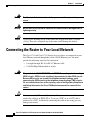
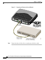
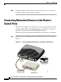
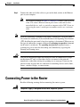
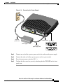
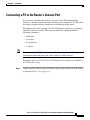
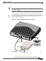
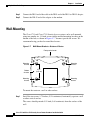
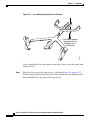
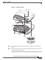
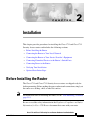
C H A P T E R
2
Installation
This chapter provides procedures for installing the Cisco 1711 and Cisco 1712
Security Access routers and includes the following sections:
•
Before Installing the Router
•
Connecting the Router to Your Local Network
•
Connecting the Router to Your Service Provider’s Equipment
•
Connecting Networked Devices to the Router’s Switch Ports
•
Connecting Power to the Router
•
Verifying Your Installation
•
Optional Installation Steps
Before Installing the Router
The Cisco 1711 and Cisco 1712 Security Access routers are shipped ready for
desktop mounting. Before making the power and network connections, simply set
the router on a desktop, shelf, or other flat surface.
Note
For instructions on wall-mounting the router, see the “Wall-Mounting” section on
page 2-14.
Be sure to read the safety information in the Regulatory Compliance and Safety
Information for Cisco 1700 Routers document that came with your router.
Cisco 1711 and Cisco 1712 Security Access Routers Hardware Installation Guide
OL-4050-02
2-1
Chapter 2
Installation
Connecting the Router to Your Local Network
Warning
Read the installation instructions before you connect the system to its power
source.
Warning
Do not work on the system or connect or disconnect cables during periods of
lightning activity.
Caution
Do not place anything on top of the router that weighs more than 10 pounds
(4.5 kg). Excessive weight on top of the router could damage the chassis.
Connecting the Router to Your Local Network
The Cisco 1711 and Cisco 1712 Security Access routers are connected to your
local Ethernet network through the yellow 10/100 Ethernet port. You must
provide the following items for this connection:
Warning
Caution
•
A straight-through, RJ-45-to-RJ-45, Ethernet cable
•
A 10/100-Mbps Ethernet hub or switch
The ports labeled 10/100 ETHERNET and CONSOLE are safety extra-low voltage
(SELV) circuits. SELV circuits should only be connected to other SELV circuits.
Because BRI circuits are treated like telephone-network voltage, avoid
connecting the SELV circuits to the telephone network voltage (TNV) circuits.
(To see translated versions of this warning, refer to the Regulatory Compliance
and Safety Information for Cisco 1700 Routers document that came with the
router.)
Always connect the Ethernet cable to the yellow ports on the router. Do not
connect the cable to an ISDN S/T or U port (on a WIC) or to an NT-1 that is
connected to a WIC. Accidentally connecting the cable to the wrong port can
damage your router.
Cisco 1711 and Cisco 1712 Security Access Routers Hardware Installation Guide
2-2
OL-4050-02
Chapter 2
Installation
Connecting the Router to Your Local Network
The Cisco 1711 Security Access router is a fixed configuration router that
includes a 1-port analog modem card (WIC-1-AM) that is installed in the WAN
interface card (WIC) slot 1.
The Cisco 1712 Security Access router is a fixed configuration router that
includes a 1-port Integrated Services Digital Network Basic Rate Interface
(ISDN-BRI) S/T interface card (WIC-1B-S/T) that is installed in WIC slot 1.
Both the Cisco 1711 and Cisco 1712 Security Access routers also include an
integrated 4-port 10/100-Mbps Ethernet switch in WIC slot 0, which is supported
only on secure Cisco IOS images.
Note
For additional information and technical specifications about the 1-port analog
modem interface, WIC-1-AM card, refer to the V.90 Modem WAN Interface Cards
on the Cisco 1700 Series Routers.
For additional information and technical specifications about the 1-port ISDN
BRI (S/T interface), WIC-1B-S/T card, refer to the Cisco 3600/2600 Series ISDN
BRI Connectivity Options.
Note
The WIC-1-AM, WIC-1B-S/T and the Ethernet switch WIC are not field
replaceable.
To connect the Cisco 1711 Security Access router or the Cisco 1712 Security
Access router to the local network, follow these steps:
Step 1
Connect one end of the cable to the yellow Ethernet port (labeled
10/100 ETHERNET), as shown in Figure 2-1 on page 2-4.
Cisco 1711 and Cisco 1712 Security Access Routers Hardware Installation Guide
OL-4050-02
2-3
Chapter 2
Installation
Connecting the Router to Your Local Network
4x LNK
ACT 3x
LNK
ACT
2x LNK
ACT
1x LNK
CONS
OLE
WIC-1-AM
B1
FDX
100
LINK
10/10
0 ET
HERN
ET
SEE
MAN
UAL
BEF
AUX
ORE
INSTAL
BRI
S/T
LATION
MODO
K
SP
CN
OH
Modem
WIC
1O
WIC-1AM
PHONE
K
+5, +1
10/100
Ethernet port
2, -1
SEE
MANUAL
BEFORE
INSTALLATION
LINE 0
or
2 VD
B1
C
CD
ACT
WIC0O
K
B2
1712
CD
WIC
4ESW
Cisco
Connecting the Router to the Local Network
B2
Figure 2-1
BRI
S/T
SEE MANUAL BEFORE INSTALLATION
WIC-1B-S/T
AUI
8
7
6
5
4
3
2
Straight-through
Ethernet cable
Step 2
91650
1
Ethernet hub or switch
(10, 100, or 10/100 Mbps)
Connect the other end of the cable to a network port on the hub or switch.
Cisco 1711 and Cisco 1712 Security Access Routers Hardware Installation Guide
2-4
OL-4050-02
Chapter 2
Installation
Connecting the Router to Your Service Provider’s Equipment
Connecting the Router to Your Service Provider’s
Equipment
You can also connect the Cisco 1711 or Cisco 1712 Security Access router to
your service provider’s broadband (xDSL or cable) modem equipment by
following these steps:
Connect one end of the cable to the yellow Ethernet port (labeled
10/100 ETHERNET). See Figure 2-2 for an illustration of this connection.
ACT 3x
LNK
ACT
2x LNK
ACT
FDX
1x LNK
100
CONS
OLE
LINK
10/10
0 ET
SEE
HERN
ET
AUX
MAN
UAL
BEF
WIC-1-AM
ORE
INSTAL
BRI
S/T
LATION
MODO
K WIC
WIC-1AM
PHONE
+5, +1
2, -1
2 VD
SEE
MANUAL
BEFORE
INSTALLATION
LINE 0
or
C
B1
10/100
Ethernet port
SP
CN
OH
Modem
1O K
CD
4x LNK
K
B2
ACT
WIC0O
B1
WIC
4ESW
Cisco
1712
Connecting the Router to Your Service Provider’s Equipment
CD
Figure 2-2
B2
Step 1
BRI
S/T
SEE MANUAL BEFORE INSTALLATION
WIC-1B-S/T
1
2
91718
Cable modem/DSL hub
Straight-through
Ethernet cable
Cisco 1711 and Cisco 1712 Security Access Routers Hardware Installation Guide
OL-4050-02
2-5
Chapter 2
Installation
Connecting Networked Devices to the Router’s Switch Ports
Step 2
Connect the other end of the cable to a network port on your service provider’s
broadband (xDSL or cable) modem equipment.
Connecting Networked Devices to the Router’s
Switch Ports
The Cisco 1711 and Cisco 1712 Security Access routers support connections from
a computer with a NIC or other networked device (such as hubs or switches) to
the router’s integrated 4-port 10/100 Mbps Ethernet switch.
Follow these steps to connect other networked devices to the router’s switch ports:
Connect one end of an Ethernet cable to the Ethernet Port (RJ-45) as shown in
Figure 2-3.
1712
ACT
WIC0
OK
4x LNK
ACT 3x
LNK
ACT
2x LNK
ACT
1x LNK
CONS
OLE
WIC-1-AM
B1
FDX
100
LINK
SEE
MAN
UAL
AUX
BEFO
RE INST
ALLA
TION
SP
CN
OH
BRI
S/T
Modem
WIC-1AM
WIC1
OK
PHONE
SEE
MANUAL
BEFORE
INSTALLATION
LINE 0
or
-12 VD
C
B1
+5, +1
2,
B2
MODO
K
Ethernet port
(RJ-45)
CD
WIC
4ESW
Cisco
Connecting Networked Devices to the Router’s Switch Ports
CD
Figure 2-3
B2
Step 1
BRI
S/T
SEE MANUAL BEFORE INSTALLATION
WIC-1B-S/T
1
2
3
4
5
Straight-through
Ethernet cable
Ethernet hub
91622
6
Cisco 1711 and Cisco 1712 Security Access Routers Hardware Installation Guide
2-6
OL-4050-02
Chapter 2
Installation
Connecting Power to the Router
Step 2
Connect the other end of the cable to a port on the hub, switch, or the Ethernet
port on your computer.
Note
Note
Caution
The example provided in Figure 2-3 on page 2-6 shows connectivity to
a hub. The router’s Ethernet switch port can be connected to other
networked devices, such as a switch or computer with a NIC. If you are
connecting the router’s switch port to another switch, use a crossover
cable.
If you are connecting a computer to the router’s switch port, it will take about
30 seconds for connectivity to be established due to the Spanning-Tree Protocol
(STP) disabling the ports until a loop-free topology is determined. When you use
this type of connection, you must configure the spanning-tree portfast command
on the router’s switch port. The spanning-tree portfast command causes a
spanning tree port to enter the forwarding state immediately, bypassing the
listening and learning states.
You can use the portfast feature on switch ports that are connected to a single
workstation or PC only to allow those devices to connect to the network
immediately, rather than waiting for spanning tree to converge. Do not use the
portfast feature on ports that are connected to networking devices such as hubs,
routers, switches, bridges, or concentrators.
Connecting Power to the Router
Read the following warnings before connecting the router to power.
Warning
The power supply is designed to work with TN power systems.
Cisco 1711 and Cisco 1712 Security Access Routers Hardware Installation Guide
OL-4050-02
2-7
Chapter 2
Installation
Connecting Power to the Router
Warning
This product relies on the building’s installation for short-circuit (overcurrent)
protection. Ensure that a fuse or circuit breaker no larger than 120VAC, 15AU.S.
(240VAC, 16A international) is used on the phase conductors (all
current-carrying conductors).
Warning
This equipment is intended to be grounded. Ensure that the host is connected to
earth ground during normal use.
Follow these steps to connect power to the router and to turn the router on:
Step 1
Connect the attached power-supply cord to the power socket (labeled +5, +12,
-12 VDC) on the router rear panel, as shown in Figure 2-4 on page 2-9.
Cisco 1711 and Cisco 1712 Security Access Routers Hardware Installation Guide
2-8
OL-4050-02
Chapter 2
Installation
Connecting Power to the Router
Connecting the Power Supply
WIC
ACT
4x LNK
ACT 3x
LNK
ACT
2x LNK
ACT
1x LNK
CONS
0 OK
FDX
100
OLE
LINK
10/10
B1
1701
0 ET
SEE
HERN
ET
AUX
MAN
UAL
BEF
ORE
CD
WIC
4ESW
Cisco
B2
INST
ALLATIO
N
MODO
K
WIC
BRI
S/T
1O K
+5, +1
Separate
power cord
2, -1
2 VD
C
Power socket
WIC-1-AM
SP
CN
OH
Modem
WIC-1AM
SEE
MANUAL
BEFORE
INSTALLATION
LINE 0
SEE MANUAL BEFORE INSTALLATION
BRI
S/T
91651
or
B1
Attached
power supply cord
PHONE
CD
Power supply
B2
Figure 2-4
WIC-1B-S/T
Step 2
Connect one end of the separate power cord to the socket on the power supply.
Step 3
Connect the other end of the separate power cord to a power outlet.
Step 4
Press the router power switch to ON ( | ).
Step 5
Confirm that the router has power by checking that the PWR LED on the front
panel is on.
Cisco 1711 and Cisco 1712 Security Access Routers Hardware Installation Guide
OL-4050-02
2-9
Chapter 2
Installation
Verifying Your Installation
Verifying Your Installation
You can verify that you have correctly installed the router by checking the
following LEDs:
•
PWR (front panel)—On when power is being supplied to the router.
•
OK (front panel)—On when the router software is loaded and functional.
Blinking means that the router is performing a power-on self-test (POST).
•
WIC0/WIC1 OK (back panel)—On when a WIC is correctly installed in the
corresponding WIC slot.
•
ETH ACT (front panel)—Blinking when there is network traffic on the local
10/100 Ethernet LAN.
•
WIC0ACT or WIC1 ACT (front panel)—See Table 1-3.
•
LINK (back panel)—On when the router is correctly connected to the local
Ethernet LAN through the 10/100 ETHERNET port.
•
MOD OK (back panel)—On when the VPN hardware encryption module is
installed and recognized by IOS.
Optional Installation Steps
This section describes some installation steps that you might or might not use,
depending on your site and on how you are configuring the router. This section
describes the following procedures:
•
Connecting a PC to the Router’s Console Port
•
Connecting a Modem on the AUX Port
•
Wall-Mounting
•
Stacking the Router
•
Unstacking the Router
Cisco 1711 and Cisco 1712 Security Access Routers Hardware Installation Guide
2-10
OL-4050-02
Chapter 2
Installation
Optional Installation Steps
Connecting a PC to the Router’s Console Port
If you want to configure the router by using the Cisco IOS command-line
interface, you must connect the router console port to a terminal or PC. The cable
and adapter required for this connection are included with the router.
To configure the router by using a PC, the PC must have some type of terminal
emulation software installed. The software should be configured with the
following parameters:
Note
•
9600 baud
•
8 data bits
•
No parity bits
•
1 stop bit
Refer to the Cisco 1700 Router Software Configuration Guide for detailed
information about configuring the router using Cisco IOS software.
To connect the Cisco 1711 or Cisco 1712 Security Access router to a terminal or
PC, follow these steps:
Step 1
Connect the blue console cable to the blue console port on the back of the router,
as shown in Figure 2-5 on page 2-12.
Cisco 1711 and Cisco 1712 Security Access Routers Hardware Installation Guide
OL-4050-02
2-11
Chapter 2
Installation
Optional Installation Steps
ACT
4x LN
K
ACT 3x
LNK
ACT
WIC0O
2x LN
K
K
FDX
100
ACT
CONS
1x LN
K
OLE
LINK
10/100
ETHE
SEE
MANU
CD
1701
B1
WIC
4ESW
Cisco
Connecting the Console Cable to the Router
B2
Figure 2-5
AL BE
RNET
FORE
INSTAL
BRI
S/T
LATION
AUX
MOD
OK W
IC 1O
+5, +1
Blue console cable
WIC-1-AM
K
2, -1
2 VD
C
Console port
SP
CN
OH
Modem
WIC-1AM
PHONE
SEE
MANUAL
BEFORE
INSTALLATION
LINE 0
CD
B2
B1
or
BRI
S/T
SEE MANUAL BEFORE INSTALLATION
WIC-1B-S/T
Step 2
91652
To PC or terminal
Connect the DB-9 end of the console cable to the console port (also called the
serial port) on your PC. If this adapter does not fit your PC console port, you
must provide an adapter that fits.
Connecting a Modem on the AUX Port
When a modem is connected to the auxiliary port, a remote user can dial into the
router and configure it. You can use the blue console cable that came in the
accessory kit.
Cisco 1711 and Cisco 1712 Security Access Routers Hardware Installation Guide
2-12
OL-4050-02
Chapter 2
Installation
Optional Installation Steps
An external modem is not required for use on the Cisco 1711 Security Access
router WIC-1-AM card.
Note
Follow these steps to connect a modem to the router, using the console cable:
Connect the RJ-45 end of the cable to the black AUX port on the back of the
router, as shown in Figure 2-6.
17xx
WIC0O
ACT
4x LN
K
ACT 3x
LNK
ACT
2x LN
K
ACT
K
FDX
100
CONS
1x LN
K
OLE
LINK
10/100
SEE
ETHE
RNET
MANUA
CD
WIC
4ESW
Cisco
Connecting a Modem to the Router’s AUX Port
B1
Figure 2-6
B2
Step 1
L BEF
ORE
INS
TALLAT
BRI
S/T
ION
AUX
MOD
OK W
IC 1O
K
+5, +1
2, -1
WIC-1-AM
2 VD
C
SP
CN
OH
Modem
AUX port (RJ-45)
WIC-1AM
PHONE
SEE
MANUAL
BEFORE
INSTALLATION
LINE 0
CD
B2
B1
or
BRI
S/T
SEE MANUAL BEFORE INSTALLATION
Console cable
DB-9-to-DB-25 adapter
91653
WIC-1B-S/T
Modem
Cisco 1711 and Cisco 1712 Security Access Routers Hardware Installation Guide
OL-4050-02
2-13
Chapter 2
Installation
Optional Installation Steps
Step 2
Connect the DB-9 end of the cable to the DB-9 end of the DB-9-to-DB-25 adapter.
Step 3
Connect the DB-25 end of the adapter to the modem.
Wall-Mounting
The Cisco 1711 and Cisco 1712 Security Access routers can be wall-mounted
using two number six, 3/4-inch screws and the molded mounting brackets on the
bottom of the hub, as shown in Figure 2-7. You must provide the screws. We
recommend using pan-head or round-head screws.
Figure 2-7
Wall-Mount Brackets—Bottom of Router
Front panel of router
Mounting
bracket
Bottom
of router
Mounting
bracket
3.75"
(9.52 cm)
Mounting
bracket
12016
Mounting
bracket
To mount the router on a wall or other surface:
Step 1
Install the two screws 3.75 inches (9.52 centimeters) horizontally apart on a wall
or other vertical surface.
The screws should protrude 0.25 inch (0.64 centimeter) from the surface of the
wall.
Cisco 1711 and Cisco 1712 Security Access Routers Hardware Installation Guide
2-14
OL-4050-02
Chapter 2
Installation
Optional Installation Steps
Step 2
Caution
Hang the router on the screws with either the left side or right side mounting
brackets so that
•
The LEDs are visible to the user—Because the LEDs indicate the router
operating status, they need to be easily visible.
•
The power supply does not hang from its cable—If the power supply is not
supported, it might disconnect from the cable that connects it to the router.
If you install the screws in drywall, use hollow-wall anchors (1/8 inch
by 5/16 inch) to secure the screws. If the screws are not properly anchored, the
strain of the cables connected to the router rear-panel connectors could pull the
router from the wall.
Stacking the Router
You can stack one Cisco 1711 Security Access router and/or one Cisco 1712
Security Access router in a four-device stack, along with other Cisco products
designed to be stacked with the router. You can stack each device directly on top
of another device.
Note
The Cisco 1711 and Cisco 1712 Security Access routers are not shipped with the
stacking equipment described in this section; however, the equipment is included
with all other Cisco products that are designed to be stacked.
Each Cisco product designed to be stacked with the router comes with a stacking
clip and a fastener for keeping the multiple devices together in a stack. Before you
stack the devices, assemble the clip and fastener as shown in Figure 2-8 on
page 2-16.
Cisco 1711 and Cisco 1712 Security Access Routers Hardware Installation Guide
OL-4050-02
2-15
Chapter 2
Installation
Optional Installation Steps
Figure 2-8
Assembling Stacking Clip and Fastener
H11542
Push plastic fastener
through small hole
at the end of the
stacking clip.
After assembling the clip and fastener, follow these steps to stack the router with
another device:
Step 1
Place the clip on top of the lower device, as shown in Figure 2-9 on page 2-17.
Slide the clip forward so that the front tabs slide into the vent slots. Make sure that
the rear hooks fit over the edge of the lower device.
Cisco 1711 and Cisco 1712 Security Access Routers Hardware Installation Guide
2-16
OL-4050-02
Chapter 2
Installation
Optional Installation Steps
Figure 2-9
Stacking the Router
Bottom of router
Cisco
WIC
4ESW
17xx
ACT
4x LNK
ACT 3x
LNK
ACT
WIC
0OK
FDX
2x LNK
100
ACT
1x LNK
CONS
OLE
LINK
10/10
0 ET
HERN
ET
AUX
Front
tabs
MOD
OK
WIC1
OK
+5, +1
2, -12
VDC
Plastic
fastener
SPEE
100B D
LED
aseT
X
10Ba
seT SOLID
BLIN
K
1 2
3 4
5 6
7 8
5X
6X
7X
8X
Back panel of
lower hub
MDI
MDI-X
Rear
hooks
91654
Rear
hooks
WIC-1-AM
SP
CN
OH
Modem
WIC-1AM
PHONE
SEE
MANUAL
BEFORE
INSTALLATION
LINE 0
CD
B2
B1
or
BRI
S/T
SEE MANUAL BEFORE INSTALLATION
WIC-1B-S/T
Step 2
Position the router onto the clips so that the rear hooks fit over the edge of the
router.
Step 3
Snap the router to the clip by pushing it down. Make sure that the plastic fastener
fits into the bottom of the router.
Cisco 1711 and Cisco 1712 Security Access Routers Hardware Installation Guide
OL-4050-02
2-17
Chapter 2
Installation
Optional Installation Steps
Unstacking the Router
Follow these steps to unstack the router from another device:
Press up on the tab over the center of the lower device to release the clip from the
vent, as shown in Figure 2-10.
Step 1
Figure 2-10 Unstacking the Router
3
2
WIC
4ESW
Cisco
17xx
ACT
4x LNK
WIC
ACT 3x
LNK
ACT
2x LNK
0OK
FDX
ACT
1x LNK
100
CONS
OLE
LINK
10
10/10
/100
0 ET
ET
HERN
HE
RNET
ET
AUX
1
MOD
OK
WIC1O
K
+5, +1
2, -1
2 VD
C
SPEE
100B D
LED
aseT
X
10Ba
seT SOLID
BLIN
K
1 2
3 4
5 6
7 8
5X
6X
7X
8X
MDI
MDI-X
WIC-1-AM
SP
CN
OH
Modem
WIC-1AM
PHONE
SEE
MANUAL
BEFORE
INSTALLATION
LINE 0
BRI
S/T
SEE MANUAL BEFORE INSTALLATION
WIC-1B-S/T
91655
CD
B2
B1
or
Cisco 1711 and Cisco 1712 Security Access Routers Hardware Installation Guide
2-18
OL-4050-02
Chapter 2
Installation
Optional Installation Steps
Step 2
Slide the clip and router toward you.
Step 3
Use both hands to lift the router and the stacking clip off the lower device.
Afterward, remove the clip from the bottom of the router.
Cisco 1711 and Cisco 1712 Security Access Routers Hardware Installation Guide
OL-4050-02
2-19
Chapter 2
Installation
Optional Installation Steps
Cisco 1711 and Cisco 1712 Security Access Routers Hardware Installation Guide
2-20
OL-4050-02