1
SECTION 5
COMMISSIONING
5.1
GAS SUPPLY INSTALLATION
Inspect the entire installation including the gas
meter, test for soundness and purge. Refer to
BS 6891 for specific instruction.
5.2
THE HEATING SYSTEM
The appliance contains components that may
become damaged or rendered inoperable by oils
and/or debris that are residual from the
installation of the system, consequently it is
essential that the system be flushed in
accordance with the following instructions.
valve full bore to remove any installation debris
from the boiler prior to lighting. Refill the boiler
and heating system as described in 5.3.
5.5
FILLING THE HOT WATER SYSTEM
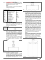
Close all hot water outlets, turn appliance
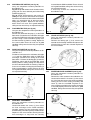
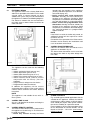
stopcock to the normal operating position (fig. 26),
slowly open each outlet until air has been expelled
and clear water is discharged. Check pipe-work
etc. for water soundness.
5.6
PRE-OPERATION CHECKS
Before attempting the initial lighting of the
appliance, the following checks must be
carried out:
● ensure all gas service valves from the meter
to the appliance are open and the supply pipe
has been properly purged
● ensure the proper electrical checks have been
carried out, (see 7.7) particularly continuity,
polarity, and resistance to earth
● ensure the 3 amp fuse – supplied with the
appliance – has been fitted.
● ensure the system has been filled, vented, and
the pressure set to 1 bar.
● ensure the flue system has been fitted properly
and in accordance with the instructions.
● ensure all appliance service valves are open.
5.7
INITIAL LIGHTING
Ensure the electrical supply to the appliance is
switched on. Move the selector switch to the
Heating & Hot Water position, ensure the time
clock is switched to an ‘ON’ position and ensure
any other external controls are also calling for
heat.
The appliance will now operate in the pre-heat
mode as described in 1.2. Once the pre-heat
function has been completed, the appliance will
operate in the central heating mode as described
in 1.3. Should the appliance fail to ignite, refer to
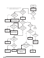
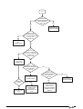
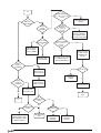
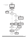
5.6 and/or section 7 (faultfinding).
5.7.1
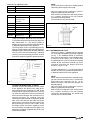
CHECKING THE BURNER PRESSURE
Although the burner pressure is factory set, it is
necessary to check it during commissioning.
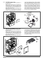
Isolate the appliance from the electrical supply
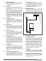
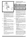
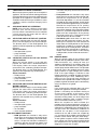
and attach a suitable manometer to the gas valve
outlet test-point (see fig. 27). Light the boiler as
described in 5.7, turn the Hot Water temperature
selector to maximum, and open fully a DHW outlet
(preferably the bath), allowing the appliance to
stabilise. Compare the reading on the manometer
with the value described in 2.3. If adjustment is
required, follow the detailed instructions in section
7 (7.3).
Once the burner pressure has been checked,
close the DHW outlet, isolate the appliance from
the electrical supply, remove the manometer, and
tighten the gas valve outlet test nipple.
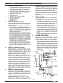
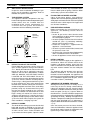
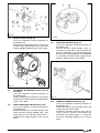
Normal
Operating
Position
Closed
Position
Filling
Position
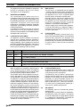
Fig. 26
5.3
5.4
INITIAL FILLING OF THE SYSTEM
Ensure both flow and return service valves are
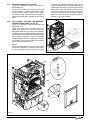
open, remove appliance casing as described in
4.7.1, identify the automatic air release valve and
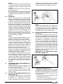
loosen the dust cap by turning the cap anticlockwise one full turn. IMPORTANT, THERE
ARE NO MANUAL AIR RELEASE VALVES
LOCATED ON THE APPLIANCE. Ensure all
manual air release valves located on the heating
system are closed. Connect the filling loop as
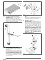
shown in fig. 6, slowly proceed to fill the system
by firstly opening the inlet valve connected to
the flow valve, and then turning the lever on the
combined stopcock and check valve, to the filling
position (see fig. 26). As water enters the system
the pressure gauge will begin to rise. Once the
gauge has reached 1 bar close both valves and
begin venting all manual air release valves,
starting at the lowest first. It may be necessary
to go back and top-up the pressure until the entire
system has been filled. Inspect the system for
water soundness, rectifying any leaks.
INITIAL FLUSHING
The whole of the heating system must be flushed
both cold and hot as detailed in 5.8. Open all
radiator or heating valves and the appliance flow
& return service valves. Drain the boiler and
system from the lowest points. Open the drain
e
19