1
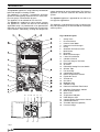
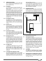
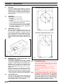
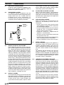
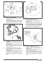
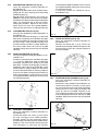
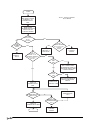
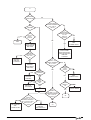
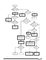
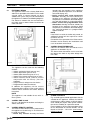
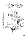
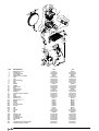
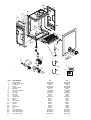
SECTION 1
1.1
1.2
1.3
1.4
2
DESIGN PRINCIPLE AND OPERATING SEQUENCE
PRINCIPLE COMPONENTS
● A fully integrated electronic control board
featuring electronic temperature control, anticycle control, pump over-run, self-diagnostic
fault indicator, full air/gas modulation.
● Low-water-content, copper heat exchanger.
● Electronic ignition with flame supervision
● Integral high-head pump
● Fan
● Expansion vessel
● Analogue pressure switch (PAD)
● Water pressure switch
● Two-stage gas valve
● Pressure gauge
● Safety valve
MODE OF OPERATION (at rest)
When the appliance is at rest and there are no
requests for heating or DHW, the following functions are active:
● pre-heat function – the pre-heat function enables the appliance to periodically light and maintain the temperature of the DHW heat exchanger. This “keep-hot” facility enables the
appliance to provide an instantaneous response to DHW requests.
● 2-stage frost-protection system – the frost-protection system protects the appliance against
the risk of frost damage. The first stage enables activation of the pump should the temperature of the appliance fall to 7°C. The second
stage becomes active when the temperature
has dropped to 3°C. Should the second stage
become active, the appliance will function on
minimum power until it reaches 30°C.
● anti-block function – the anti-block function enables the pump and divertor valve actuator, to
be energised for short periods, when the appliance has been inactive for more than 19hours.
MODE OF OPERATION (Heating)
When there is a request for heat via the
programmer/time clock and/or any external
control, the pump and fan are started, the fan
speed will modulate until the correct signal
voltage is received at the control PCB. At this
point an ignition sequence is enabled.
Ignition is sensed by the electronic circuitry to
ensure flame stability at the burner. Once
successful ignition has been achieved, the
electronic circuitry increases the gas rate to 75%
for a period of 15 minutes. Thereafter, the boiler’s
output will either be increase to maximum or
modulate to suit the set requirement. When the
appliance reaches the desired temperature the
burner will shut down and the boiler will perform
a three-minute anti-cycle (timer delay).
When the request for heat has been satisfied the
appliance pump and fan may continue to operate
to dissipate any residual heat within the
appliance.
MODE OF OPERATION (DHW)
When there is a request for DHW via a hot water
outlet or tap, the pump and fan are started, the
fan speed will modulate until the correct signal
voltage is received at the control PCB. At this
point an ignition sequence is enabled.
During DHW request LED (31, fig. 1) is ON.
Ignition is sensed by the electronic circuitry to
ensure flame stability at the burner. Once
successful ignition has been achieved, the
electronic circuitry increases the gas rate to
maximum or will modulate output to stabilise the
temperature. In the event of the appliance
exceeding the desired temperature the burner
will shut down until the temperature drops.
When the request for DHW has been satisfied
the appliance pump and fan may continue to
operate to dissipate any residual heat within the
appliance.
1.5
SAFETY DEVICES
When the appliance is in use, safe operation is
ensured by:
● a water pressure switch that monitors system
water pressure and will de-activate the pump,
fan and burner should the system water
pressure drop below the rated tolerance.
● a high limit thermostat that over-rides the
temperature control circuit to prevent or
interrupt the operation of the burner.
● an analogue pressure switch (PAD) that
checks the operation of the fan and flue
thereby allowing safe operation of the burner.
● a sensor that interrupts the operation of the
appliance if the condense pipe becomes
blocked.
● a safety valve which releases excess pressure
from the primary circuit.
1.6
OPTIONAL ACCESSORIES
The Syntesi e is suitable for use with a range of
optional accessories that enable enhanced
operation and/or applications. These include:
● RC05 remote control – the RC05 remote
control enables the appliance to be controlled,
adjusted, and monitored from another location
or room. The RC05 can also be used as a room
thermostat or programmable room thermostat.
● external sensor – used in conjunction with the
RC05 the external sensor enables the
appliance to automatically adjust its outlet flow
temperature in response to the outside
temperature.
Air Intake
Flue Outlet
Latent Heat
Collector
PAD
Main Heat
Exchanger
Expansion
vessel
Main
Burner
Gas Valve
AARV
Domestic
Heat
Exchanger
Pump
Diverter
Valve Motor
Pressure
Switch
Fig. 2
DHW Flow
Switch
A
B
C
D
e