1
FCC COMPLIANCE STATEMENT
FOR AMERICAN USERS
This equipment generates and uses radio frequency energy and if not installed and used
properly, that is, in strict accordance with the manufacturer’s instructions, may cause
interference to radio and television reception. It has been type tested and found to comply
with the limits for a Class B computing device in accordance with the specifications in
Subpart J of Part 15 of FCC rules, which are designed to provide reasonable protection
against such interference in a residential installation. However, there is no guarantee that
interference will not occur in a particular installation. If this equipment does cause interference to radio or television reception, which can be determined by turning the equipment off and on, the user is encouraged to try to correct the interference by one or more of
the following measures:
- Reorient the receiving antenna
- Relocate the computer with respect to the receiver
- Move the computer into a different outlet so that computer and receiver are on
different branch circuits.
If necessary, the user should consult the dealer or an experienced radio/television technician for additional suggestions. The user may find the following booklet prepared by the
Federal Communications Commission helpful:
“How to Identify and Resolve Radio-TV Interference Problems.”
This booklet is available from the U.S. Government Printing Office, Washington DC
20402, Stock No. 004-000-00345-4.
All rights reserved. No part of this publication may be reproduced, stored in a retrieval system,
or transmitted, in any form or by any means, mechanical, photocopying, recording or otherwise, without the prior written permission of Epson America, Inc. No patent liability is
assumed with respect to the use of the information contained herein. While every precaution
has been taken in the preparation of this book, Epson America, Inc. and the author assume no
responsibility for errors or omissions. Neither is any liability assumed for damages resulting
from the use of the information contained herein.
Baby printout on cover reprinted with permission of Apple Computer Inc., copyright 1984
Apple is a registered trademark of Apple Computer, Inc.
Centronics is a registered trademark of Data Computer Corporation.
Concept is a trademark of Corvus Systems, Inc.
DEC is a registered trademark of Digital Equipment Corporation.
FX-80, FX-100, RX-80, and RX-100 are trademarks of Epson America, Inc.
HX-20 Notebook Computer is a trademark of Epson America, Inc.
IBM-PC is a registered trademark of International Business Machines Corporation.
Microsoft is a trademark of Microsoft Corporation.
NEC is the NEC Information Systems, Inc., a subsidiary of Nippon Electronic Company, Ltd.
QX-10 is a trademark of Epson America, Inc.
TRS-80 is a registered trademark of Radio Shack, a division of Tandy Corporation.
80 Micro is published by Wayne Green Publishers.
Copyright© 1984 by Epson America, Inc.
Torrance, California 90505
ii
P8294017
Preface
The User’s Manual for the FX Series printers consists of two volumes: Tutorial and Reference. This volume, the Tutorial, is arranged
in the following logical groupings:
Introduction (for everyone)
Programmer’s Easy Lesson (for experienced users)
Hardware description: Chapter 1
Software introduction: Chapter 2
Control of the way characters look: Chapters 3 to 6
Control of the way pages look: Chapters 7 to 9
Printer graphics: Chapters 10 to 14
User-defined characters: Chapters 15 and 16
Using everything together: Chapter 17
A complete table of contents for this volume is after this preface. For
your convenience, there is an index at the end of each volume covering the complete two-volume set. You can therefore find all the references to any topic in either one.
Conventions Used in This Manual
We provide sample BASIC programs that allow you to see how
various commands control the printer’s capabilities. Frequently we
start with a few program lines and then make several changes and
additions to end up with a substantial program. We suggest that you
use your SAVE command after each change to prevent losing programs because of power fluctuations or other accidents. When you
can RUN a program, we show the results you should expect.
In our sample programs, we use Microsoft’” BASIC, which is
widely used in personal computers. Because there are several slightly
different versions of Microsoft BASIC and because your computer
iii
may use a version of BASIC other than Microsoft, you may need to
modify some of the programs in this manual before they will run.
Appendix F offers help, as do the next several paragraphs.
Methods for sending BASIC print and listing commands to the
screen and to the printer vary widely. We have used PRINT and LIST
as the commands for the screen display, and LPRINT and LLIST as
commands for the printer. You may have to change those to the form
used by your system.
If, for example, your system uses the PR#1 and PR#0 commands,
you will need to change all instances of PRINT in our programs. Since
we use PRINT to report progress to your screen and that command
does not affect the printing, the easiest modification is to delete such
PRINT statements. For example,
38 FOR D=1 TO 17: PRINT "ROW";D
would become:
39 FOR D=1 TO 17
because the only purpose of the PRINT statement is to display on the
screen information that is not absolutely essential to the program.
Any BASIC system automatically provides a carriage return (and
some BASICS add a line feed) after every program line that includes a
PRINT or LPRINT command, whether that line prints text or not. To
prevent the carriage return, we have you place a semicolon at the end
of such program lines. You will see this technique throughout the
manual.
A few versions of BASIC use semicolons between any two control
codes that fall on one program line, as in:
LPRINT CHR$(27);CHR$(52)
If you use such a version of BASIC, you will need to add semicolons
as appropriate.
After the ESCape code-CHR$(27)-the FX always expects another code. The second code tells the printer which mode to turn on or
off, and you may enter it in either of two formats. One format is like
the ESCape code-you use a number in parentheses after CHR$, such
as CHR$(l). The other format is shorter since it uses only an alphanumeric symbol within quotation marks, such as “E” or “@“. We usually
use the latter format.
iv
This format allows you to shorten a program line by combining a
command and its print string. In the case of Double-Strike, for instance, the quoted letter “G” turns the mode on and "H" turns it off. To
see how combining the code with a print string works, compare:
10 LPRINT CHR$(27)"G";"DOUBLE-STRIKE PRINT"
with:
10 LPRINT CHR$(27)"GDOUBLE-STRIKE PRINT"
The second program line may look peculiar, but it gives the same
output that the first version does. The G is not printed on the paper;
instead, it is interpreted by the printer as part of the ESCape sequence.
In long programs with DATA statements or subroutines, we use
END after the line that is executed last, but older BASIC systems require the use of STOP at such points. If yours is one of these, you
should change our ENDS to STOPS.
When the presence of one or more blank spaces in a program line is
especially important, we use a special character ( , pronounced
‘blank’) to represent the spaces. This makes it easier for you to count
the number you need. For example, the following:
SAMPLE STRING"
means that you should type in one blank space for each
"
SAMPLE STRING"
The use of the symbol makes it easy for you to count the eight spaces
needed between the quotation mark and the beginning of the first
word. The
also calls your attention to single blank spaces that are
needed immediately before or after a quotation mark. For example,
the following makes clear that you must type one space between the
quotation mark and the word “and’:
LPRINT " AND EASY TO TURN OFF"
When we include a programming REMark in a program line, it is
always preceded by an apostrophe (‘), the short form of the BASIC
command, REM. For example, we use:
10 LPRINT CHR$(27)"@"
' Reset Code
and
99 ' Data lines for graphics
V
The computer ignores these remarks; they merely serve to help programmers understand at a glance the way a program is working. You
may type them in or not, depending on whether you think you will
want them in the future.
We use the caret symbol (^) to indicate exponents. For example:
x = Y^2
means let X equal Y raised to the second power. Some computer systems use an up-arrow (t), which prints as a left bracket ([) on FX
printers.
At the end of each chapter, a Summary section provides a concise
review of the chapter’s subject matter and a list of the control codes (if
any) that have been covered. For listings of the control codes in numerical order and in functional groupings, see Appendixes B and C.
When we refer to an FX mode by name, we capitalize it:
Compressed Mode
Italic Mode
Pica Mode
Script Modes
and, for clarity, we capitalize such names even when the word mode
does not appear: Script characters and Italic print.
vi
FX Series Printer User’s Manual
Volume 1 Contents
Preface . . . . . . . . . . . . . . . . . . . . . . . . . . . . . . . . . . . . . .
Conventions Used in This Manual . . . . . . . . . . . . . . . .
iii
iii
List of Figures . . . . . . . . . . . . . . . . . . . . . . . . . . . . . . . . .
xiii
List of Tables . . . . . . . . . . . . . . . . . . . . . . . . . . . . . . . . .
xvii
Introduction . . . . . . . . . . . . . . . . . . . . . . . . . . . . . . . . . .
Inside the Printer . . . . . . . . . . . . . . . . . . . . . . . . . . . . . .
Inside This Manual . . . . . . . . . . . . . . . . . . . . . . . . . . . .
2
2
Programmer’s Easy Lesson . . . . . . . . . . . . . . . . . . . . . .
First Steps . . . . . . . . . . . . . . . . . . . . . . . . . . . . . . . . . . . .
Ticket Program . . . . . . . . . . . . . . . . . . . . . . . . . . . . . . .
Ticket Program Description . . . . . . . . . . . . . . . . . . . . .
1
The FX Printers . . . . . . . . . . . . . . . . . . . . . . . . . . . . . . .
Additional Supplies and Accessories . . . . . . . . . . . . . .
Printer Location . . . . . . . . . . . . . . . . . . . . . . . . . . . . . . .
Printer Preparation . . . . . . . . . . . . . . . . . . . . . . . . . . . .
Paper separator . . . . . . . . . . . . . . . . . . . . . . . . . . . . .
Covers . . . . . . . . . . . . . . . . . . . . . . . . . . . . . . . . . . . .
Manual-feed knob . . . . . . . . . . . . . . . . . . . . . . . . . . .
DIP switches . . . . . . . . . . . . . . . . . . . . . . . . . . . . . .
Ribbon Installation . . . . . . . . . . . . . . . . . . . . . . . . . .
Paper Loading . . . . . . . . . . . . . . . . . . . . . . . . . . . . . . . .
FX-80: built-in tractor feed . . . . . . . . . . . . . . . . . . . .
FX-80 and FX-100: friction feed . . . . . . . . . . . . . . . .
FX-80 and FX-100: removable
tractor unit (optional on the FX-80) . . . . . . . . . . .
Top-of-form position . . . . . . . . . . . . . . . . . . . . . . . . .
Paper-thickness lever . . . . . . . . . . . . . . . . . . . . . . . . .
Starting Up . . . . . . . . . . . . . . . . . . . . . . . . . . . . . . . . . . .
Control panel . . . . . . . . . . . . . . . . . . . . . . . . . . . . . . .
The FX tests itself . . . . . . . . . . . . . . . . . . . . . . . . . . . .
1
7
7
8
10
13
16
16
17
17
18
19
20
23
24
24
28
29
32
32
32
35
35
vii
BASIC and the Printer . . . . . . . . . . . . . . . . . . . . . . . . .
BASIC Communications . . . . . . . . . . . . . . . . . . . . . . . .
Character strings . . . . . . . . . . . . . . . . . . . . . . . . . . . .
BASIC print commands . . . . . . . . . . . . . . . . . . . . . .
ASCII and BASIC basics . . . . . . . . . . . . . . . . . . . . . .
Control codes . . . . . . . . . . . . . . . . . . . . . . . . . . . . . . .
Escape-CHR$(27)-and other CHR$ commands
Change Commands . . . . . . . . . . . . . . . . . . . . . . . . . . . .
Reset Code . . . . . . . . . . . . . . . . . . . . . . . . . . . . . . . . .
Mode cancelling codes . . . . . . . . . . . . . . . . . . . . . . . .
DELete and CANcel . . . . . . . . . . . . . . . . . . . . . . . . .
Alternate Formats for ESCape Sequences . . . . . . . . . .
Summary . . . . . . . . . . . . . . . . . . . . . . . . . . . . . . . . . . . .
37
38
39
39
40
41
3
Print Pitches . . . . . . . . . . . . . . . . . . . . . . . . . . . . . . . . . .
Dot-Matrix Printing . . . . . . . . . . . . . . . . . . . . . . . . . . . .
Main columns . . . . . . . . . . . . . . . . . . . . . . . . . . . . . .
Intermediate positions . . . . . . . . . . . . . . . . . . . . . . . .
Modes for Pitches . . . . . . . . . . . . . . . . . . . . . . . . . . . . .
Pica and Elite Modes . . . . . . . . . . . . . . . . . . . . . . . . .
Compressed Mode . . . . . . . . . . . . . . . . . . . . . . . . . . .
Mode priorities . . . . . . . . . . . . . . . . . . . . . . . . . . . . .
Pitch Mode Combinations . . . . . . . . . . . . . . . . . . . . . .
Expanded Mode . . . . . . . . . . . . . . . . . . . . . . . . . . . . .
Multiple print pitches on one line . . . . . . . . . . . . . . .
Summary . . . . . . . . . . . . . . . . . . . . . . . . . . . . . . . . . . . .
49
49
50
51
52
52
53
55
56
56
58
59
4
Print Quality . . . . . . . . . . . . . . . . . . . . . . . . . . . . . . . . .
Bold Modes . . . . . . . . . . . . . . . . . . . . . . . . . . . . . . . . . .
Double-StrikeMode . . . . . . . . . . . . . . . . . . . . . . . . .
Emphasized Mode . . . . . . . . . . . . . . . . . . . . . . . . . . .
Proportional Mode . . . . . . . . . . . . . . . . . . . . . . . . . .
Mixing Modes . . . . . . . . . . . . . . . . . . . . . . . . . . . . . . . .
Summary . . . . . . . . . . . . . . . . . . . . . . . . . . . . . . . . . . . .
2
5
viii
Dress-Up Modes and Master Select . . . . . . . . . . . . . . .
Four Modes . . . . . . . . . . . . . . . . . . . . . . . . . . . . . . . . . . .
Underline Mode . . . . . . . . . . . . . . . . . . . . . . . . . . . . .
Script Modes: Super and Sub . . . . . . . . . . . . . . . . . .
Italic Mode . . . . . . . . . . . . . . . . . . . . . . . . . . . . . . . . .
More Mode Combinations . . . . . . . . . . . . . . . . . . . . . .
Master Select . . . . . . . . . . . . . . . . . . . . . . . . . . . . . . .
Master Select combinations . . . . . . . . . . . . . . . . . . .
Summary . . . . . . . . . . . . . . . . . . . . . . . . . . . . . . . . . . . .
42
44
45
45
46
46
47
61
61
61
62
64
65
66
69
69
69
71
72
73
73
76
78
6
7
8
Special Printing Features . . . . . . . . . . . . . . . . . . . . . . . .
Backspace . . . . . . . . . . . . . . . . . . . . . . . . . . . . . . . . . . . .
Overstrikes . . . . . . . . . . . . . . . . . . . . . . . . . . . . . . . . .
Offsets . . . . . . . . . . . . . . . . . . . . . . . . . . . . . . . . . . . . .
Unidirectional Mode . . . . . . . . . . . . . . . . . . . . . . . . . . .
International Characters . . . . . . . . . . . . . . . . . . . . . . . .
Special Speeds . . . . . . . . . . . . . . . . . . . . . . . . . . . . . . . .
Half-SpeedMode . . . . . . . . . . . . . . . . . . . . . . . . . . . .
Immediate-Print Mode (FX-80 only) . . . . . . . . . . . .
Summary . . . . . . . . . . . . . . . . . . . . . . . . . . . . . . . . . . . .
81
81
81
Line Spacing and Line Feeds . . . . . . . . . . . . . . . . . . . . .
Line Spacing . . . . . . . . . . . . . . . . . . . . . . . . . . . . . . . . . .
Preset line spacing . . . . . . . . . . . . . . . . . . . . . . . . . . .
Variable line spacing . . . . . . . . . . . . . . . . . . . . . . . . .
Microscopic line spacing . . . . . . . . . . . . . . . . . . . . . .
Line Feeds . . . . . . . . . . . . . . . . . . . . . . . . . . . . . . . . . . . .
One-time, immediate line feed . . . . . . . . . . . . . . . . .
Reverse feed (FX-80 only) . . . . . . . . . . . . . . . . . . . . .
Summary . . . . . . . . . . . . . . . . . . . . . . . . . . . . . . . . . . . .
93
93
93
95
98
98
Forms Control . . . . . . . . . . . . . . . . . . . . . . . . . . . . . . . .
Form Length Control . . . . . . . . . . . . . . . . . . . . . . . . . . .
Form feed distance . . . . . . . . . . . . . . . . . . . . . . . . . . .
Not-so-standard forms . . . . . . . . . . . . . . . . . . . . . . .
Paper Perforation Skip . . . . . . . . . . . . . . . . . . . . . . . . .
Skip command . . . . . . . . . . . . . . . . . . . . . . . . . . . . . .
DIP switch skip . . . . . . . . . . . . . . . . . . . . . . . . . . . . .
Single-Sheet Adjustment . . . . . . . . . . . . . . . . . . . . . . . .
Summary . . . . . . . . . . . . . . . . . . . . . . . . . . . . . . . . . . . .
82
83
85
88
89
89
90
99
99
101
103
103
103
105
107
107
109
109
110
ix
Margins and Tabs . . . . . . . . . . . . . . . . . . . . . . . . . . . . .
Margins.. . . . . . . . . . . . . . . . . . . . . . . . . . . . . . . . . . . . .
Left margin . . . . . . . . . . . . . . . . . . . . . . . . . . . . . . . . .
Margins and pitches . . . . . . . . . . . . . . . . . . . . . . . . .
Right margin . . . . . . . . . . . . . . . . . . . . . . . . . . . . . . .
Both margins . . . . . . . . . . . . . . . . . . . . . . . . . . . . . . .
Tabs.. . . . . . . . . . . . . . . . . . . . . . . . . . . . . . . . . . . . . . . .
Horizontal tab usage . . . . . . . . . . . . . . . . . . . . . . . . .
Variable horizontal tabs . . . . . . . . . . . . . . . . . . . . . .
Vertical tab usage . . . . . . . . . . . . . . . . . . . . . . . . . . . .
Ordinary vertical tabs . . . . . . . . . . . . . . . . . . . . . . . .
Vertical tab channels . . . . . . . . . . . . . . . . . . . . . . . . .
Summary . . . . . . . . . . . . . . . . . . . . . . . . . . . . . . . . . . . .
113
113
113
114
116
118
118
119
121
122
10
Introduction to Dot Graphics . . . . . . . . . . . . . . . . . . . .
Dots and Matrixes . . . . . . . . . . . . . . . . . . . . . . . . . . . . .
Print Head . . . . . . . . . . . . . . . . . . . . . . . . . . . . .
Graphics Mode . . . . . . . . . . . . . . . . . . . . . . . . . . . . . . .
Pin Labels . . . . . . . . . . . . . . . . . . . . . . . . . . . . . . . . . . . .
First Graphics Programs . . . . . . . . . . . . . . . . . . . . . . . .
Straight line . . . . . . . . . . . . . . . . . . . . . . . . . . . . . . . .
Slash . . . . . . . . . . . . . . . . . . . . . . . . . . . . . . . . . . . . . .
Large caret . . . . . . . . . . . . . . . . . . . . . . . . . . . . . . . . .
Wave pattern . . . . . . . . . . . . . . . . . . . . . . . . . . . . . . .
Diamond pattern . . . . . . . . . . . . . . . . . . . . . . . . . . . .
Summary . . . . . . . . . . . . . . . . . . . . . . . . . . . . . . . . . . . .
131
11
Varieties of Graphics Density . . . . . . . . . . . . . . . . . . . .
Graphics Programming Tips . . . . . . . . . . . . . . . . . . . . .
Graphics and the Reset Code . . . . . . . . . . . . . . . . . .
Graphics and low ASCII codes . . . . . . . . . . . . . . . .
Density Varieties . . . . . . . . . . . . . . . . . . . . . . . . . . . . . .
High-Speed Double-Density Graphics Mode . . . . .
Low-Speed Double-Density Graphics Mode . . . . . .
Quadruple-Density Graphics Mode . . . . . . . . . . . . .
Moredensities . . . . . . . . . . . . . . . . . . . . . . . . . . . . . .
More Graphics Programming Tips . . . . . . . . . . . . . . .
Reassigning alternate graphics codes . . . . . . . . . . . .
Nine-Pin Graphics Mode . . . . . . . . . . . . . . . . . . . . .
Pin Combination Patterns . . . . . . . . . . . . . . . . . . . . . . .
Repeated patterns . . . . . . . . . . . . . . . . . . . . . . . . . . .
Repeated DATA numbers . . . . . . . . . . . . . . . . . . . . .
Summary . . . . . . . . . . . . . . . . . . . . . . . . . . . . . . . . . . . .
143
9
x
123
126
128
131
132
134
135
137
138
139
139
140
141
142
143
144
144
145
146
148
149
149
150
150
152
154
155
156
157
12
Design Your Own Graphics . . . . . . . . . . . . . . . . . . . . .
Planning Process . . . . . . . . . . . . . . . . . . . . . . . . . . . . . .
STRATA Program . . . . . . . . . . . . . . . . . . . . . . . . . . . . .
Three-Dimensional Program . . . . . . . . . . . . . . . . . . . .
First version of 3D program . . . . . . . . . . . . . . . . . . .
Other versions . . . . . . . . . . . . . . . . . . . . . . . . . . . . . .
Summary . . . . . . . . . . . . . . . . . . . . . . . . . . . . . . . . . . . .
159
160
163
165
170
171
13
Plotter Graphics . . . . . . . . . . . . . . . . . . . . . . . . . . . . . . .
Arrays . . . . . . . . . . . . . . . . . . . . . . . . . . . . . . . . . . . . . . .
DIMension and arrays . . . . . . . . . . . . . . . . . . . . . . .
Filling arrays . . . . . . . . . . . . . . . . . . . . . . . . . . . . . . .
Circle Plotting . . . . . . . . . . . . . . . . . . . . . . . . . . . . . . . .
Ones become dots . . . . . . . . . . . . . . . . . . . . . . . . . . .
Pin firing sequences . . . . . . . . . . . . . . . . . . . . . . . . . .
Code solutions . . . . . . . . . . . . . . . . . . . . . . . . . . . . . .
Higher resolution . . . . . . . . . . . . . . . . . . . . . . . . . . . .
Reflections . . . . . . . . . . . . . . . . . . . . . . . . . . . . . . . . .
Exploding galaxy . . . . . . . . . . . . . . . . . . . . . . . . . . . .
Big bang . . . . . . . . . . . . . . . . . . . . . . . . . . . . . . . . . . .
Summary . . . . . . . . . . . . . . . . . . . . . . . . . . . . . . . . . . . .
173
173
176
176
177
178
179
180
181
183
184
185
187
14
Symmetrical Graphics Patterns . . . . . . . . . . . . . . . . . .
Pin Pattern Calculation . . . . . . . . . . . . . . . . . . . . . . . . .
Graphics Width Settings . . . . . . . . . . . . . . . . . . . . . . . .
Pattern Printout . . . . . . . . . . . . . . . . . . . . . . . . . . . . . . .
Variations . . . . . . . . . . . . . . . . . . . . . . . . . . . . . . . . . . . .
Summary . . . . . . . . . . . . . . . . . . . . . . . . . . . . . . . . . . . .
189
192
193
193
195
197
15
User-Defined Characters . . . . . . . . . . . . . . . . . . . . . . . .
Preparation . . . . . . . . . . . . . . . . . . . . . . . . . . . . . . . . .
Character Definition . . . . . . . . . . . . . . . . . . . . . . . . . . .
Design . . . . . . . . . . . . . . . . . . . . . . . . . . . . . . . . . . . . .
Dots into DATA . . . . . . . . . . . . . . . . . . . . . . . . . . . .
Attribute byte . . . . . . . . . . . . . . . . . . . . . . . . . . . . . .
Proportional print . . . . . . . . . . . . . . . . . . . . . . . . . . .
Printing User-Defined Characters . . . . . . . . . . . . . . . . .
Downloading Command . . . . . . . . . . . . . . . . . . . . . . .
Defining More Characters . . . . . . . . . . . . . . . . . . . . . . .
Redefining Control Codes . . . . . . . . . . . . . . . . . . . . . . .
Mode Strings . . . . . . . . . . . . . . . . . . . . . . . . . . . . . . . . .
STRATA . . . . . . . . . . . . . . . . . . . . . . . . . . . . . . . . . . . . .
Summary . . . . . . . . . . . . . . . . . . . . . . . . . . . . . . . . . . . .
199
200
200
201
202
203
203
205
207
207
208
211
212
212
159
xi
16
17
xii
Combining User-Defined Characters . . . . . . . . . . . . . .
Large Letters: Double Wide . . . . . . . . . . . . . . . . . . . . .
Large Letters: Double High . . . . . . . . . . . . . . . . . . . . . .
Giant Letters: Double High and Double Wide . . . . . .
Core Sets . . . . . . . . . . . . . . . . . . . . . . . . . . . . . . . . . . . .
Line Graphics . . . . . . . . . . . . . . . . . . . . . . . . . . . . . . . . .
Summary . . . . . . . . . . . . . . . . . . . . . . . . . . . . . . . . . . . .
215
215
217
217
Business Application . . . . . . . . . . . . . . . . . . . . . . . . . . .
Preparation . . . . . . . . . . . . . . . . . . . . . . . . . . . . . . . . .
Barchart . . . . . . . . . . . . . . . . . . . . . . . . . . . . . . . . . . . . .
Statement Form . . . . . . . . . . . . . . . . . . . . . . . . . . . . . . .
999 REM: The End . . . . . . . . . . . . . . . . . . . . . . . . . . . .
227
227
227
231
238
Index . . . . . . . . . . . . . . . . . . . . . . . . . . . . . . . . . . . . . . . . .
239
223
225
226
List of Figures
Easy-1
Easy-2
FX ticket program . . . . . . . . . . . . . . . . . . . . . . . . . .
Ticket to success . . . . . . . . . . . . . . . . . . . . . . . . . . .
8
10
1-1
1-2
1-3
1-4
1-5
1-6
1-7
1-8
1-9
1-10
1-11
1-12
1-13
1-14
1-15
1-16
1-17
1-18
1-19
1-20
1-21
1-22
The FX-80 and FX-100 printers . . . . . . . . . . . . . . .
Printer parts . . . . . . . . . . . . . . . . . . . . . . . . . . . . . . .
Paperpath . . . . . . . . . . . . . . . . . . . . . . . . . . . . . . . .
Paper separator . . . . . . . . . . . . . . . . . . . . . . . . . . . .
Protective lids . . . . . . . . . . . . . . . . . . . . . . . . . . . . .
Tractor covers . . . . . . . . . . . . . . . . . . . . . . . . . . . . .
Manual-feed knob . . . . . . . . . . . . . . . . . . . . . . . . . .
DIP switch vent . . . . . . . . . . . . . . . . . . . . . . . . . . . .
DIP switch location . . . . . . . . . . . . . . . . . . . . . . . . .
DIP switch factory settings . . . . . . . . . . . . . . . . . .
Ribbon insertion . . . . . . . . . . . . . . . . . . . . . . . . . . .
Printer readied for paper insertion . . . . . . . . . . . . .
Pin feeder adjustment . . . . . . . . . . . . . . . . . . . . . . .
Loading the FX-80 . . . . . . . . . . . . . . . . . . . . . . . . . .
Tractor unit release . . . . . . . . . . . . . . . . . . . . . . . . .
Tractor unit installation . . . . . . . . . . . . . . . . . . . . . .
Hook and stud . . . . . . . . . . . . . . . . . . . . . . . . . . .
Adjusting the pin feeders . . . . . . . . . . . . . . . . . . . .
Top of form . . . . . . . . . . . . . . . . . . . . . . . . . . . . . . .
Paper thickness adjustment . . . . . . . . . . . . . . . . . .
Cable connection . . . . . . . . . . . . . . . . . . . . . . . . . . .
Sample automatic test . . . . . . . . . . . . . . . . . . . . . . .
14
15
17
18
19
19
20
21
22
22
25
26
27
27
28
30
30
31
33
34
35
36
2-1
Italic listing . . . . . . . . . . . . . . . . . . . . . . . . . . . . . . .
43
3-1
3-2
3-3
3-4
3-5
3-6
3-7
Dot-matrix characters . . . . . . . . . . . . . . . . . . . . . . .
Theprinthead . . . . . . . . . . . . . . . . . . . . . . . . . . . . .
Main columns . . . . . . . . . . . . . . . . . . . . . . . . . . . . .
Intermediate positions . . . . . . . . . . . . . . . . . . . . . . .
Pica and Elite letters . . . . . . . . . . . . . . . . . . . . . . . .
Pitch comparison . . . . . . . . . . . . . . . . . . . . . . . . . .
Pica and Expanded letters . . . . . . . . . . . . . . . . . . . .
49
50
51
51
53
53
57
4-1
4-2
4-3
Single-Strike and Double-Strike letters . . . . . . . . .
Single-Strike, Expanded and Emphasized letters .
Mode priorities . . . . . . . . . . . . . . . . . . . . . . . . . . . .
62
63
66
xiii
5-1
5-2
5-3
Master Select Program . . . . . . . . . . . . . . . . . . . . . .
Master Select choices . . . . . . . . . . . . . . . . . . . . . . .
Dress-up combinations . . . . . . . . . . . . . . . . . . . . . .
74
75
77
6-1
6-2
Bidirectional line . . . . . . . . . . . . . . . . . . . . . . . . . . .
Unidirectional line . . . . . . . . . . . . . . . . . . . . . . . . . .
84
84
7-1
7-2
7-3
Default line spacing . . . . . . . . . . . . . . . . . . . . . . . . .
Cascading STAIR STEPS . . . . . . . . . . . . . . . . . . . .
Staggering STAIR STEPS . . . . . . . . . . . . . . . . . . . .
94
96
100
8-1
8-2
8-3
8-4
Setting the top of form . . . . . . . . . . . . . . . . . . . . . .
Two-inch form feed . . . . . . . . . . . . . . . . . . . . . . . . .
Two-line form feed . . . . . . . . . . . . . . . . . . . . . . . . .
Standardskip . . . . . . . . . . . . . . . . . . . . . . . . . . . . .
104
106
106
108
9-1
9-2
9-3
9-4
9-5
9-6
9-7
9-8
9-9
9-10
9-11
9-12
9-13
Left margin setting . . . . . . . . . . . . . . . . . . . . . . . . .
Listing at new margin . . . . . . . . . . . . . . . . . . . . . . .
Absolute left margin . . . . . . . . . . . . . . . . . . . . . . . .
Right margin set incorrectly . . . . . . . . . . . . . . . . . .
Right margin set correctly . . . . . . . . . . . . . . . . . . .
Default horizontal tabs . . . . . . . . . . . . . . . . . . . . . .
Tabs with text and numbers . . . . . . . . . . . . . . . . . .
Variable horizontal tabs . . . . . . . . . . . . . . . . . . . . .
Absolute horizontal tabs . . . . . . . . . . . . . . . . . . . .
Ordinary vertical tabs . . . . . . . . . . . . . . . . . . . . . .
Text at tab stop . . . . . . . . . . . . . . . . . . . . . . . . . . . .
Absolute vertical tabs . . . . . . . . . . . . . . . . . . . . . . .
Printout of multipage channels . . . . . . . . . . . . . . .
114
115
115
116
117
119
120
121
122
124
125
126
128
10-1
10-2
10-3
10-4
Pins numbered sequentially . . . . . . . . . . . . . . . . . .
Dot pattern in two line spacings . . . . . . . . . . . . . .
Pins labelled uniquely . . . . . . . . . . . . . . . . . . . . . . .
Pin combinations . . . . . . . . . . . . . . . . . . . . . . . . . .
133
133
136
137
11-1
11-2
11-3
11-4
11-5
11-6
11-7
High-Speed Double-Density dots . . . . . . . . . . . . . .
No overlapping dots . . . . . . . . . . . . . . . . . . . . . . . .
Overlapping dots . . . . . . . . . . . . . . . . . . . . . . . . . .
Seven density modes . . . . . . . . . . . . . . . . . . . . . . . .
Nine-pin usage . . . . . . . . . . . . . . . . . . . . . . . . . . . . .
Printout using bottom pin . . . . . . . . . . . . . . . . . . .
Curling design . . . . . . . . . . . . . . . . . . . . . . . . . . . . .
147
147
148
150
153
154
155
xiv
12-4
12-5
12-6
12-7
12-8
12-9
12-10
12-11
STRATA layout . . . . . . . . . . . . . . . . . . . . . . . . . . .
STRATA logo . . . . . . . . . . . . . . . . . . . . . . . . . . . . .
STRATA program . . . . . . . . . . . . . . . . . . . . . . . . . .
Corner of the FX-80 design . . . . . . . . . . . . . . . . . . .
FX-80 figure . . . . . . . . . . . . . . . . . . . . . . . . . . . . . . .
Program for FX-80 figure . . . . . . . . . . . . . . . . . . . .
FX-100 figure . . . . . . . . . . . . . . . . . . . . . . . . . . . . . .
Program for FX-100 figure . . . . . . . . . . . . . . . . . . .
More distinct version . . . . . . . . . . . . . . . . . . . . . . .
Most distict version . . . . . . . . . . . . . . . . . . . . . . . . .
Reversed version . . . . . . . . . . . . . . . . . . . . . . . . . . .
161
162
163
164
168
168
169
170
171
172
172
13-1
13-2
13-3
13-4
13-5
13-6
13-7
Computer memory as sketch pad . . . . . . . . . . . . .
Array in memory and on paper . . . . . . . . . . . . . . .
Ones and zeros become dots and blanks . . . . . . .
Labelled cell . . . . . . . . . . . . . . . . . . . . . . . . . . . . . . .
Plotting a circle . . . . . . . . . . . . . . . . . . . . . . . . . . . .
Displaying an array . . . . . . . . . . . . . . . . . . . . . . . .
Divide and conquer . . . . . . . . . . . . . . . . . . . . . . . .
174
174
175
175
177
178
182
14-1
14-2
14-3
14-4
14-5
14-6
Printing the array contents . . . . . . . . . . . . . . . . . . .
Pattern sets . . . . . . . . . . . . . . . . . . . . . . . . . . . . . . .
Program for SYMMETRY . . . . . . . . . . . . . . . . . . .
Symmetric pattern 1 . . . . . . . . . . . . . . . . . . . . . . . .
Symmetric pattern 2 . . . . . . . . . . . . . . . . . . . . . . . .
Symmetric pattern 3 . . . . . . . . . . . . . . . . . . . . . . . .
191
191
194
195
196
196
15-1
15-2
15-3
15-4
15-5
ROM and user-defined characters . . . . . . . . . . . . .
User-defined E . . . . . . . . . . . . . . . . . . . . . . . . . . . . .
Incorrectly designed E . . . . . . . . . . . . . . . . . . . . . . .
Pins chosen by attribute byte . . . . . . . . . . . . . . . . .
Attribute byte conversions . . . . . . . . . . . . . . . . . . .
199
201
202
203
204
16-1
16-2
16-3
16-4
16-5
16-6
16-7
16-8
16-9
Side-by-side characters . . . . . . . . . . . . . . . . . . . . . .
Double high and wide character . . . . . . . . . . . . . .
Program for giant G . . . . . . . . . . . . . . . . . . . . . . . .
Giant G . . . . . . . . . . . . . . . . . . . . . . . . . . . . . . . . . .
Data for AMES . . . . . . . . . . . . . . . . . . . . . . . . . . . .
Games seem same . . . . . . . . . . . . . . . . . . . . . . . . . .
Messages in three pitches . . . . . . . . . . . . . . . . . . . .
Tracks . . . . . . . . . . . . . . . . . . . . . . . . . . . . . . . . . . . .
Interlace . . . . . . . . . . . . . . . . . . . . . . . . . . . . . . . . . .
216
218
220
221
222
222
223
224
225
12-1
12-2
12-3
xv
17-1
17-2
17-3
17-4
xvi
Barchart . . . . . . . . . . . . . . . . . . . . . . . . . . . . . . . . . .
Program for BARCHART . . . . . . . . . . . . . . . . . . .
Statement form . . . . . . . . . . . . . . . . . . . . . . . . . . . .
Program for STATEMENT . . . . . . . . . . . . . . . . . .
228
230
232
234
List of Tables
1-1
DIP switch functions . . . . . . . . . . . . . . . . . . . . . . . .
23
2-1
2-2
2-3
Several computers’ print LIST commands . . . . . .
Several computers’ printer activating commands .
ASCII codes on the FX . . . . . . . . . . . . . . . . . . . . . .
38
40
42
3-1
Summary of print pitches . . . . . . . . . . . . . . . . . . . .
60
4-1
Summary of modes . . . . . . . . . . . . . . . . . . . . . . . . .
67
5-1
5-2
Master Select Quick Reference Chart . . . . . . . . . .
Print types . . . . . . . . . . . . . . . . . . . . . . . . . . . . . . . .
76
78
6-1
6-2
6-3
6-4
Some special characters . . . . . . . . . . . . . . . . . . . . .
International characters in Roman typeface . . . . .
International characters in Italic typeface . . . . . . .
International DIP switch settings . . . . . . . . . . . . . .
85
87
7-1
Line-spacing commands . . . . . . . . . . . . . . . . . . . . .
102
11-1
Graphics Modes . . . . . . . . . . . . . . . . . . . . . . . . . . .
151
14-1
Variables for SYMMETRY . . . . . . . . . . . . . . . . . . .
190
15-1
International character locations . . . . . . . . . . . . . .
210
16-1
ASCII pattern . . . . . . . . . . . . . . . . . . . . . . . . . . . . .
219
87
88
xvii
Introduction
FX Features
Epson’s MX series of printers attracted enough attention to become
the most popular line of printers in the industry. Our FX printers follow in the same grand tradition. The FX printers’ power-packed
assortment of features includes:
l
l
Upward compatibility with most MX III features
Several different print modes that can be combined to produce a
variety of print styles. These include:
Roman and Italic print fonts
Six different print pitches
Two kinds of bold printing
l
l
l
l
l
l
l
Master Select feature for instant use of any one of 16 popular print
combinations
Proportionally spaced characters for professional looking documents
Easy-to-use Underline and Super/Subscript Modes
Detailed forms handling capability, including the setting of horizontal and vertical tabs, margins, form length, a skip-over-perforation
feature, and variable line feeds
Up to 233 characters per line with the FX-100™ for spreadsheet users
User-definable character sets. With this powerful feature you can
create your own alphabets and special symbols
High-resolution graphics capability with six densities to let you create your own charts, diagrams, figures, and illustrations
l
International character sets
l
Typewriter simulation mode with the FX-80™
l
l
Program debugging mode (hexadecimal dump of codes received
from the computer)
Fast print speed-160 characters per second-for rapid processing
of documents
l
2K print buffer for smooth operation
l
Adjustable tractor unit for narrow forms
l
Both friction- and tractor-feed capability
l
Replaceable print head
l
Easy-to-reach DIP switches to customize printer features.
l
Epson reliability, quality, and support
In short, the FX is loaded with features that will challenge your ability
to put them to work. This manual can help you use one or all of them.
Inside the Printer
The FX printers contain two kinds of internal memory: ROM (Read
Only Memory) and RAM (Random Access Memory). There are 12K
bytes (approximately 12,000 characters) of ROM. This unchangeable
memory contains all the logic required for the various print features as
well as the patterns for all the built-in character sets.
The FX also contains a RAM memory buffer that stores up to 2K
bytes of text and printer commands as they are received from the computer. This frees your computer so that you can continue working
while the FX is printing. You can also use RAM another way; you can
define your own set of characters and then store them in RAM so that
you can print them at will.
It is always tempting (though not always wise) to start playing with
a new printer the instant it is out of the box. Because the FX is a sophisticated piece of equipment, it is important that you understand what
the printer will do and how to operate it before you start printing.
Inside This Manual
This manual will guide you on a carefully planned tour of the various features of the FX printers. In these pages, you can learn how to
use your computer to control the printer for a large variety of applications.
2
You can use this manual as a reference, a tutorial study guide, or
some combination of the two.
l
l
l
l
l
For those of you who want to use the printer for one simple application (like listing BASIC programs or using a word processing package), a description of the hardware and an overview of the software
may be all that’s necessary. In this case, you need only Chapter 1,
the Quick Reference Card at the back of Volume 2, and a knowledge of the program you are using. You can always learn about the
FX’s advanced features at a later time. (You might, for instance,
someday want to modify a word processing software package so
that its printer driver uses special FX features.) The lessons will be
waiting for you.
For those who prefer to roll up their sleeves and see how the printer
works, we’ve included sample programs to demonstrate each of the
printer’s features.
For those who want only a quick and easy reference, the comprehensive Table of Contents, the Appendixes, and the Index provide
ready access to information.
For computer professionals and other experienced users who simply
can’t wait to find out what the printer will do, regardless of the
consequences, we have a special section entitled “Programmer’s
Easy Lesson.” It gets you up and running fast, then turns you loose
on a program that demonstrates several of the printer’s features.
This program, the Appendixes, and the Quick Reference Card will
bring you quickly up to speed.
For those who are already familiar with the MX or RX series of
printers, Appendix E provides a summary of the differences
between the FX, the RX, and the MX.
3
Think of the manual as your personal guide in your exploration of
the FX’s many features.
For a preview of what your programs can produce, take a look at the
following potpourri of print modes and graphics.
4
Programmer’s Easy Lesson
Before you start, note that we haven’t claimed that one easy lesson
will make you an FX maestro. It takes more than one lesson to learn
the full value of the feature-packed FX printer. In fact, the more time
you spend with this manual, the more your printer will cooperate
with your every command. But some of you want to see something
from a new printer right now-no matter what. The next few pages
are especially for you.
If you get stuck, the proper set-up procedures are covered in full in
Chapter 1.
First Steps
1. Make all connections with the power OFF! Connect your FX to
your computer via the printer cable that you purchased separately.
(Some computers require special printer interface boards, also purchased separately).
2. To use continuous-feed printer paper with pin-feed holes, set the
friction-control lever and the paper bail toward the front of the
printer. If you are using the FX-80, pull the paper under the plastic
separator and through the paper path. If you are using the FX-100,
you may need to first install the tractor unit, then pull the paper
under it. In case the paper starts to jam on either model, refer to
Chapter 1 for tips on inserting paper. As you straighten the paper,
you will probably need to adjust the pin feeders.
To use either a single sheet of paper or roll paper without pinfeed holes on the FX-80, first move the pin feeders out of the way. If
a tractor unit is installed on your FX-100, you will need to remove
it. Then, for either model, push the friction-control lever toward
the rear of the printer, pull the paper bail forward, and insert the
paper under the plastic separator. Use the manual-feed knob to
7
feed the paper through. If you use single sheets of paper, the paperout sensor will cause a beep and stop the printing whenever the
bottom edge passes the sensor. You can shut off the sensor by
changing DIP switches as shown in Chapter 1.
3. Turn the printer and computer on and load a short BASIC pro-
gram. Then send a listing to the printer (using LLIST, LIST “I”‘, or
whatever your computer’s listing command is). You should get a
single-spaced listing. If the printout is double-spaced or printed
without line spacing, you’ll have to change a DIP switch.
Since there are many implementations of the BASIC programming language, it is impossible to write one set of programs that
will work on every computer system. This means you may need to
modify our programs to suit your system. In Appendix F we discuss such compatibility problems and suggest solutions for several
popular computers.
Ticket Program
Here is an example program, written in BASIC, that shows off a lot
of the FX printer’s features. The program can give you a good survey
of print control. If you don’t understand one or more features, you
can check the index to find what part of this manual covers it.
10 N=29: E$=CHR$(27): H$=CHR$(137)
20 LPRINT E$"1";E$"D"CHR$(26)CHR$(1);
30 LPRINT E$":"CHR$(0)CHR$(0)CHR$(0);
40 LPRINT E$"%"CHR$(1)CHR$(0);
50 LPRINT E$"&"CHR$(0)"0:";
60 FOR Y=1 TO 11: LPRINT CHR$(11);
70 FOR X=1 TO 11: READ D: LPRINT CHR$(D);: NEXT X
80 NEXT Y: LPRINT E$"U1";
90 FOR X=1 TO N: LPRINT CHR$(95);: NEXT X:
LPRINT E$"A"CHR$(6)
100 LPRINT "7"H$" 9";E$"1"
110 LPRINT "7 ";: FOR X=1 TO 25: LPRINT ":";:
NEXT X: LPRINT H$" 9"
120 LPRINT "7 :"H$": 9"
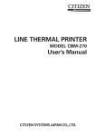
Figure Easy-1. FX ticket program
8
Ticket Program Description
This is not a complete explanation of the program. That’s what the
rest of the manual is for. But this brief, line-by-line description should
help those of you who wish to analyze the program.
10 Stores values in variables for easy access. E$ holds the ESCape
code, CHR$(27).
20 Uses ESCape "1" to set the line spacing to 7/2X-inch and the
ESCape “D” sequence to set a horizontal tab stop at column 26.
30 Uses the ESCape ":" sequence to copy the entire ROM character
set into RAM.
40 Designates RAM as the source for the active character set.
50 Prepares the printer to redefine characters “0” through “:“.
60 Sets a counter for the 11 letters being defined, and selects the
attribute byte of each new character.
70 Reads the data that defines the letters (11 sets of ll). (See Chapter
15 for additional information on lines 30 through 70.)
80 Turns on the Unidirectional Print Mode.
90 Prints the top of the ticket and sets the line spacing to 6/72-inch.
100 Prints the newly defined symbol “7” (left ticket border), tabs to
the next stop, prints the other border (9) and sets the line spacing
back to 7/72-inch.
10
110 Prints the outside border, then the top of the inside border (which
was defined as the “:” character).
120 Prints another line of borders.
130 Prints more borders, then uses the Master Select to turn on
Emphasized Double-Strike Pica. Also turns on Italic and Underline Modes.
140 Prints TICKET TO SUCCESS, then resets the FX to its defaults,
including Pica, but does not affect the redefined characters.
150 Produces two more border lines.
160 Prints the upper half of the FX letters in Expanded Emphasized
printing. The user-defined character 0 produces the top of the F
and 2 produces the top of the X.
170 Turns off Expanded and Emphasized Modes and prints SERIES in
Superscript Mode and then prints the right side of the border.
180 Prints the bottom half of the FX letters.
190 Turns OFF the codes, prints PRINTERS in Subscript, then prints
a border.
200 Prints borders.
210 Prints borders, then switches to Compressed and prints BY. Sets,
with ESCape ”!X”, Emphasized Double-Strike Pica, and prints
EPSON. This new mode automatically turns off Compressed.
220 Sets Superscript Mode (Escape “SO”), returns to normal print
(Escape”!@“), prints INC in Superscript, then cancels Script
Mode, then prints borders.
230 Prints another line of borders, then sets Master Select with
ESCape ”!Q”, giving Double-Strike Elite.
240 Prints GENERAL ADMISSION, resets the FX to its defaults, and
prints right borders.
250 Prints the outside borders and the bottom of the inside border.
260 Prints the outside borders and sets line spacing to l/72-inch.
270 Prints the bottom of the outside border.
11
280 Returns the printer to its defaults.
300-330 Provides data for the FX letters as user-defined characters
0-3.
350-410 Provides data for the ticket borders.
12
Chapter 1
The FX Printers
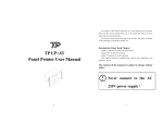
Once you’ve unpacked your new printer, the first thing you should
do is make sure you have all of the parts. With the FX-80 or FX-100
printer, you should receive the items shown in Figure 1-1:
1. The printer itself
2. A manual-feed knob
3. A paper separator
4. Two protective lids
5. One ribbon cartridge (in a box)
6. This FX Series Printer User’s Manual
The FX-80 has a tractor built into its platen for handling continuousfeed paper between 91/2 and 10 inches in width. To handle narrower
continuous-feed paper, you must purchase the optional FX-80 tractor
unit.
On an FX-100 you will find these items installed:
7. A tractor unit
8. A dust cover for the tractor unit
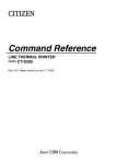
As you unpack your printer, you may want to save all protective
plastic, paper, and cardboard to use in the future for repacking. Figure
1-2 displays with labels the parts of each model that we discuss in this
chapter.
13
Figure 1-1. The FX-80 and FX-100 printers
14
Figure 1-2. Printer parts
15
Additional Supplies and Accessories
The following items may be purchased separately from your Epson
dealer:
Printer cable or interface kit. Each computer system has its own way
of connecting to a printer. Some computers need a cable only, others
require both a cable and board. The FX printers use the Centronics
standard parallel interface scheme described in Appendix K. If your
computer expects to communicate through a serial rather than
through a parallel interface, you must purchase a serial board for your
FX. Your Epson dealer stocks a variety of FX interface boards as well
as cables.
Printer paper. FX printers are designed to accommodate several types
and sizes of paper. Both printers include tractors so that you can use
continuous-feed paper with pin-feed holes and friction mechanisms so
that you can use paper without these holes.
Ribbon cartridge replacement. The expected life of a cartridge is three
million characters (roughly 1,000 pages of text).
Print head replacement. The expected life of a print head is one hundred million characters (over 30,000 pages of text).
Roll paper holder. For the FX-80, you may purchase an optional rollpaper holder.
Printer Location
Naturally, your printer must sit somewhere near the computer (the
length of the cable is the limiting factor), but there are other considerations in finding a choice location for your computer/printer setup.
For instance, you may want to find an electrical outlet that is not
controlled by a switch-since a switch may be accidentally shut off
while you have valuable information stored in memory Be sure the
outlet is grounded (do not use an adapter plug). To minimize power
fluctuations, avoid using an outlet on the same circuit breaker with
large electrical machines or appliances. Finally, for continuous-feed
operations you must allow enough room for the paper to flow freely,
as in Figure 1-3.
16
Figure 1-3. Paper path
Printer Preparation
Once you’ve found a good home for FX, you’ll need to do some
preparing before you can print. This section describes the first steps,
which include installing a few parts, checking the setting of some
internal switches, and then inserting the ribbon cartridge.
Note: The printer should be turned OFF during all set-up operations.
Paper separator
To install the paper separator, hold it vertically so that it rests on the
two slots at the back of the metal frame as shown in Figure 1-4. Press
down gently but firmly until the separator snaps into place.
To remove the separator, pull up on the left side first, letting the
right side slide out of its slot.
17
Figure 1-4. Paper separator
Covers
For protection from dust and foreign objects and for quiet operation, FX printers use two types of covers. When you use the friction
feed on either the FX-80 or the FX-100 or the built-in tractor on the
FX-80, use the pair of flat protective lids (Figure 1-5). When you use
the removable tractor unit, use the tractor cover (Figure 1-6).
Install the center protective lid by inserting tabs into slots (one tab
per side on the FX-80, two on the FX-100). Fit the left side of the lid
over the friction-control lever (you may need to slightly bow the middle of the lid before you can snap the tabs into their slots). When you
need to change the setting of the pin feeder on the FX-80 or install a
tractor unit on either model, remove this lid by giving it a slight
upward tug.
Install and remove either the front protective lid or the tractor cover
by using the hinge posts at the front of the printer opening. This
arrangement allows you to easily raise and lower the cover to load
paper or ribbon. To install the cover, hold it at its full vertical position,
slide the right hinge fitting over the right hinge post, and set the left
18
fitting over its post. Lower the cover. To remove the cover, move it to
its full vertical position and then lift it up and a little to the left.
Figure 1-5. Protective lids
Figure 1-6. Tractor cover
Manual-feed knob
The manual-feed knob (Figure 1-7) can aid you in loading and
adjusting paper. To install the manual-feed knob, hold it in position on
19
the right side and twist until the flat sides of rod and fitting match.
Push the knob straight in with a steady pressure. To remove, pull
straight out.
Figure 1-7. Manual-feed knob
DIP switches
Several tiny switches, called DIP (for Dual In-line Package)
switches, are located inside the FX. They control a number of important printer functions, such as line-feed adjustment, the paper-out sensor, the beeper, and the default print modes. You can check these
switches now, or you can skip to the ribbon section and check the
switches later.
The design of the FX printer allows easy access to the internal
switches. They are located under the upper-right vent. To remove the
vent, you need a Phillip’s-head screwdriver. Once the top screw is
removed, take the vent off by pressing down and sideways with the
palm of your hand (Figure 1-8).
Do not replace the screw because in the course of this manual, we
will sometimes suggest that you reset switches. Keep the screw in a
safe spot so that you can replace it later.
Locate the two DIP switch assemblies as shown in Figure 1-7 and
check that they are set as shown in Figure 1-10.
20
Figure 1-8. DIP switch vent
21
These switches are set at the factory, and most of them you will
never need to touch. You may, however, want to take the time now to
match up the switches with their functions, as shown in Table 1-1. For
a further discussion of the DIP switches, see Appendix E.
Figure 1-9. DIP switch location
Figure 1-10. DIP switch factory settings
Always turn the power off (with the switch on the left side of the
printer) before touching any internal switch. The printer checks most
switch settings only at power-up. If you make changes when the
power is on, they may be ignored until you turn the printer off, then
back on. So set all switches with the power off. Use a non-metallic
object, such as the back of a pen, to change the DIP switches.
One switch deserves your immediate attention; it is the switch
labelled 4 on switch assembly 2. This switch (let’s call it 2-4) adjusts the
automatic line feed (the movement of the paper up one line) at the end
of each print line to match your computer system’s needs.
22
Table 1-1. DIP switch functions
Switch 1
Some computer interfaces automatically send a line-feed code to
the printer at the end of each print line. Other interfaces send only a
carriage return (which returns the print head to its left-most position),
and rely on the printer to perform the automatic line feed. Switch 2-4
enables the FX to match either requirement. With switch 2-4 on, the
printer automatically adds a line feed to every carriage return it
receives from the computer; with the switch off, it expects the computer to provide the line feed. If you are not sure what your system
requires, leave the switch the way you find it, but remember that you
can adjust this if your first printing occurs either all on one line or with
the lines spaces twice as far apart as you requested.
We recommend two changes now. Turning switch 1-2 on adds a
slash to the zero character, which makes program listings easier to
read. If you are not going to create your own characters, turn switch
1-4 on to take advantage of the internal 2K buffer.
Ribbon installation
First, be sure the printer is turned off and move the print head to the
middle of the platen.
Remove the ribbon cartridge from its packing materials. Holding
the cartridge by the plastic fin on the top, guide the pair of tabs at each
23
end of the cartridge into the corresponding slots in the printer frame
(Figure 1-11). The cartridge should snap neatly into place.
With the paper bail resting on the platen, you can tuck the ribbon
between the metal ribbon guide and the black print head.
As Figure 1-11 suggests, you can ease the ribbon into place with the
deft application of a dull pencil. To remove any slack in the ribbon,
turn the ribbon knob in the direction of the arrow.
Note: When you replace a ribbon, remember that the print head may
be hot from usage; be careful.
Paper Loading
How you load your paper depends on which model of FX you have
and which type of paper and feeder you are using. This section covers
each type of paper loading and then illustrates the top-of-form position on both models.
Both the FX-80 and the FX-100 include tractors so that you can use
continuous-feed paper with pin-feed holes and friction mechanisms so
that you can use paper without these holes.
Continuous-feed paper usually comes fanfolded into a box and has
pin-feed holes arranged on half-inch tear-off strips at each side. This
allows the printer’s pin feeders to engage the paper and pull it evenly
through the printer. After printing you can remove the tear-off strips
and separate the pages.
The FX-80’s built-in tractor handles continuous-feed paper that is
9½ inches wide, which is the standard 8½-inch width with the tearoff strips removed. The FX printers’ removable tractor units (optional
on the FX-80, standard on the FX-100) handle continuous paper in
widths from 4 inches to the width of the platen - 10 inches on the
FX-80,16 inches on the FX-100. The friction feeder on each FX handles
all papers narrower than the width of the platen.
To refresh your memory about names of the parts, refer back to
Figure 1-2.
FX-80: built-in tractor feed
The FX-80’s built-in tractor will accommodate 9½- to 10-inch wide
continuous-feed paper with pin-feed holes. You should have few problems loading it if you follow these instructions carefully.
24
Figure 1-11. Ribbon insertion
25
Figure 1-12. Printer readied for paper insertion
l
l
l
l
Be sure the printer is turned off. Lift the front protective lid and
move the print head to the middle of the platen.
Remove the center protective lid.
Pull the paper bail and the friction-control lever toward the front of
the printer. Your printer should now look like Figure 1-12.
Adjust the pin-feed levers to approximate the width of paper you
are using. Pull the levers forward to release the pin feeders, move
them so their arrows line up with the correct position on the scale
(e.g., for 9.5 for 9½ -inch paper), and push the levers backward to
lock them into position (Figure 1- 13).
If you are using fanfold paper, start by positioning your paper
directly beneath or behind the printer, as in Figure 1-14, so that the
paper won’t kink or pull to one side.
l
26
Insert the paper under the plastic separator, guiding it with your left
hand while you slowly roll the manual-feed knob clockwise. It is
Figure 1-13. Pin feeder adjustment
very important to keep the paper straight so that the pins on both
sides engage at the same time. If the paper does not move smoothly,
remove it by reversing the manual-feed knob and start again with an
unwrinkled sheet.
Figure 1-14. Loading the FX-80
27
l
As the paper comes up the front of the platen, watch to be sure that
it is feeding under the black edges of the pin feeders. If your paper is
wrinkling as it comes through, you may need to readjust the pin
feeders.
Reinstall the center protective lid underneath the paper. Push the
paper bail back against the paper and close the front protective lid.
You are now ready to set the top of form, as shown at the end of this
section.
l
The friction-control should remain toward the front of the
printer as long as the tractor is used.
l
FX-80 and FX-100: friction feed
The friction feed is for paper without pin-feed holes.
Before using the friction feed on the FX-80, disengage the pin feeders
by pulling the levers forward, then move the feeders as far toward the
edges as possible. Remove the center protective lid if it is on.
If a tractor unit is installed on the top, remove it. Push both tractorunit release levers back (one is shown close up in Figure 1-15). Rock
the unit up and back, pulling it gently toward the rear of the printer.
The tractor will come off easily-you should not have to tug on the
unit to remove it.
Figure 1-15. Tractor unit release
28
Now follow these steps to load your paper into the friction feeder:
l
l
l
Be sure the printer is turned off, Lift the front protective lid and
move the print head to the middle of the platen (refer back to Figure
1-12). Pull the paper bail up.
Engage the friction-control mechanism by pushing the frictioncontrol lever to the back.
Guide the paper under the paper separator and the platen with your
left hand, while turning the manual-feed knob with your right
hand.
If you hear a crinkling noise, stop. This can result from the paper
getting slightly wrinkled; it is best to remove the paper and start
over with an unwrinkled sheet.
l
Do not pull on the paper as it comes up from the platen; leave the
friction feeder in charge. Push the paper bail back against the paper,
close the front protective lid and reinstall the center protective lid.
You are now ready to set the top of form, as shown at the end of this
section.
There is one more point to consider if you are printing on single
sheets of paper. DIP switch 1-3 is set to active at the factory, and this
means that the paper-out feature will sound the FX’s beeper and halt
printing whenever it senses the bottom of your sheet of paper. In practice, this means that without deactivating the sensor, you won’t be
able to print on the bottom of a single sheet of paper. You can, usually,
deactivate the paper-out sensor easily by changing switch 1-3. Some
computer systems, however, ignore the setting of DIP switch 1-3 (See
Appendix F.)
FX-80 and FX-100: removable tractor unit
(optional on the FX-80)
The removable tractor will accommodate pin-feed paper in any
width from four inches to the width of the platen.
To install the optional tractor unit on the FX-80, begin by removing
the center protective lid if it is on. Move the built-in pin feeders as far
as possible to the right.
To add the tractor unit to either the FX-80 or the FX-100, hold the
tractor unit over the printer with the gears to your right as shown in
Figure 1-16. Lower the rear hooks over the rear studs as shown in
Figure 1-17, pushing the unit back against the studs to ensure that both
29
sides of the tractor assembly are firmly in place. Rock the front of the
unit downward, pressing firmly until it locks into place.
Figure 1-16. Tractor unit installation
Figure 1-17. Hook and stud
30
To load the paper into the unit, use this procedure:
l
l
l
l
l
Be sure the printer is turned off; then open the front protective lid to
move the print head to the middle of the platen.
Pull the paper bail and the friction-control lever toward the front of
the printer (refer back to Figure 1-12).
Insert the paper under the paper separator and the platen and push
the paper through to the front.
Position the pin feeders, using the pin-feed locking levers to make
the adjustment. One is shown in Figure 1-18.
Raise the black covers of both pin feeders and ease the paper over
the pins. Adjust the paper or pin feeders as necessary so that there
are no wrinkles or dips in the paper. Now you are ready to set the
top of form.
Figure 1-18. Adjusting the pin feeders
31
Top-of-form position
After you have loaded the paper, you should set it to the top of
form, which is the position of the print head when you turn the printer
on. (Since the computer term form corresponds to the word page, it
may be easier for you to think of this as the top of the page.) To make
this setting, advance the paper until a perforation lies slightly below
the top of the ribbon.
The relationship between the perforation and the printhead is the
same on both models of the printer, as you can see in Figure 1-19. You
need to leave some paper above the ribbon so that the paper moves up
smoothly.
When you have the position set, lower the bail and replace or reposition the lids or cover.
Although you have arranged the paper correctly, you are not done.
The printer will not recognize the top of form until the next time you
turn it on. The FX considers a form to be 66 lines long unless you
change this length as discussed in Chapter 8.
Paper-thickness lever
The paper-thickness lever shown in Figure 1-20 moves the print
head to accommodate various paper thicknesses. The factory sets it
for ordinary paper (which is 1/5OOth of an inch thick), but you can
adjust it for printing one original and up to two copies. For thick paper
or multiple copies, move it toward the front. Do not use the extreme
rear setting, however. This position is used for head alignment and
will shorten the life of the print head if used in normal operation.
starting up
It is finally time to connect the printer to the computer; remember
that some computers need interface kits and all need cables. First make
sure the power switch is off. Connect the printer end of the printer
cable to the connector at the right rear of the FX (as shown in Figure
32
Figure 1-19. Top of form
1-21). The other end of the cable plugs into your computer. If your
cable includes grounding wires, be sure to fasten the wires to the
grounding screws at each end.
With the paper loaded, turn the printer on with the toggle switch at
the left-rear comer of the FX. You get a little dance from the print head
and three lights go on: the POWER light, the READY light, and the
ON LINE light. If the ON LINE and READY lights are not on, push
the button marked ON LINE. If the PAPER OUT light is on, the paper
is not loaded correctly.
33
Figure 1-20. Paper thickness adjustment
34
Figure 1-21. Cable connection
Control panel
When the control panel’s ON LINE light is on, the printer and computer are in direct communication and the FF (form feed) and LF (line
feed) buttons have no effect. Go ahead, try pushing one.
To use the FF and LF button; press the ON LINE button to turn it
off. Now you can see what the other buttons do.
Press the LF button briefly, then release it. That produces one line
feed. Now hold the LF button down for a moment to produce several
line feeds.
The FF button advances the paper one complete page(form). If you
hold the button down, it advances several forms. Ideally, you’ll set the
top-of-form position before you turn on the printer. That way, your
printing can start on the first line of the paper. If you turn the printer
on while the print head is sitting in the middle of a form, that is precisely where the next form will start when you press the FF button or
your program sends the FX a form feed.
Remember that the ON LINE light has to be off for the FF and LF
buttons to work.
The FX tests itself
Now it’s time to see how your new FX operates. If you’re using an
FX-100, be sure you have full-width (15-inch printing area) paper
35
loaded because the printer’s test uses all 136 columns. Turn the printer
completely off (with the switch on the left side of the printer), press
down the LF button, and turn the printer back on again while still
holding down the LF button.
Figure 1-22. Sample automatic test
Figure 1-22 shows the FX’s automatic test, which prints the standard
characters that are stored in the printer. The test pattern continues
until you turn the printer off. If you let it run long enough, you’ll see
two sets (Roman and Italic) of upper- and lower-case letters, plus
many other characters.
If you plan to use your FX printer primarily for word processing or
with some other commercial software, you are now ready to follow
the printer set-up instructions in your software menu or manual.
Because most software packages include set-up routines for dot matrix
printers, this set up may be merely a matter of specifying which
printer you are using.
In case your software asks for specifications that you do not understand, check the appendixes or consult your computer dealer.
Some programs allow you to insert codes to activate such FX features as Emphasized and Compressed printing. Your software manual
will tell you how to use this feature, and the Quick Reference Card in
Volume 2 will give you the necessary ESCape and control codes.
36
Chapter 2
BASIC and the Printer
While you read this manual, you’ll be testing your FX with programs in the BASIC language. You can, of course, use another language with your printer; see Appendixes A through D for the ASCII
and ESCape codes that your software manual will explain how to use.
Here we use BASIC because it is the most popular language for personal computers.
One of the simplest things you can do with any FX printer is print
listings of your BASIC programs. You merely load a BASIC program
into the computer and send the LISTing output to the printer instead
of to the screen.
Unfortunately, different computer systems access the printer in
different ways. For example, most computers that use Microsoft
BASIC send PRINT or LIST commands to the printer by adding a
leading L to a screen command: LPRINT, LLIST, etc. Some other computer systems use PRINT# in place of LPRINT Another group uses
PR#l to route information to the printer and PR#O to restore the flow
of information to the screen. If you aren’t familiar with your system’s
command conventions, consult its manual.
We will use the LPRINT and LLIST commands for our examples in
this manual because the widespread acceptance of Microsoft BASIC
makes these commands as close to a standard as exists in this industry.
But remember that you may need to modify such commands to match
the unique aspects of your system. The Preface and Appendix F can
help.
Once you have discovered how your computer communicates with
the printer, load a BASIC program into memory. Now list it onto the
printer, using your computer’s version of the LLIST command. Some
examples are shown in Table 2-1.
37
Table 2-1. Several computers’ print LIST commands
If your listing is more than a page long (or if you didn’t start the
listing at the top of a page), your printer may have printed right over
the perforation. Set DIP switch 2-3 to the on position, and the printer
will automatically skip over the perforation. We discuss this further in
Chapter 8.
Meanwhile, printing a program LISTing is a fundamental function
of the printer. Be sure you manage this before continuing (if you have
trouble, consult your computer’s manual for help).
BASIC Communications
Part of the difficulty in controlling communications between computer and printer is the lack of a completely standard coding scheme.
When your computer sends out a numeric code for the letter A, you
naturally want your printer to interpret that code as an A. Most manufacturers of computers, printers, and software use the American
Standard Code for Information Interchange (ASCII, pronounced askee) to code such frequently used characters as the letters of the alphabet, numerals, and keyboard symbols. Of the 256 ASCII numbers,
most are codes for specific characters; some are codes for such computer or printer functions as sounding a beep or performing a carriage
return.
The ASCII standard does not yet allow for the advanced features in
today’s computers and printers. Individual manufacturers therefore
adjust the codes to suit their own needs, which means that we are
often faced with compatibility problems between printers and computers. (To compare your computer’s version of the ASCII table with
the FX’s version, see your computer manual and this manual’s Appendix A.) You can usually overcome the code inconsistencies by sending
control codes for advanced printer functions in care of a special ASCII
code that is called an ESCape code. The next five subsections discuss
these matters in more detail.
38
Character strings
The character-string (or CHR$) function converts any decimal
number from zero through 255 to a character or action. Its format is
CHR$ followed by a number in parentheses, for example, CHR$(84).
The character-string command follows a PRINT or LPRINT command and causes your computer system to send an ASCII code to the
computer’s screen or to the printer. What gets printed or performed is
determined by the particular modified ASCII table that is used by
your system. Where the printing or action happens-on your screen
or your printer-depends on the print command that precedes the
character-string command.
For a fast check on what your computer does with this function, try
printing a few characters on your computer’s screen. The usual format
for this is PRINT CHR$(n). The n represents one of the numbers from
zero to 255, each one of which accesses a unique character or action.
Try typing this:
10 PRINT CHR$(65)
and RUNning it. Since most computers use the numbers from 32 to
127 to mean the ASCII set of characters, you should see a capital A on
the screen.
It’s the numbers less than 32 and greater than 127 that produce
different results on nearly every brand of computer. Try entering:
10 PRINT CHR$(193)
and RUNning it. If you don’t see anything on the screen, don’t worry.
Remember that this was just a quick check. We are mainly interested
in sending that 193 to the printer, and what it prints on the screen is
not as important right now.
BASIC print commands
Well then, what happens when you send such a non-standard code
as 193 to the printer? To test this out, you need to know what program
commands your computer uses to activate the printer. Some typical
command sequences are shown in Table 2-2.
39
Table 2-2. Several computers’ printer
activating commands
Check your computer’s reference manual and type in the commands appropriate to your computer. Then type RUN.
With any luck, you will get an Italic capital A on the printer:
If nothing prints, it’s time to double-check your computer manual
and cable connections. Make sure the printer is ON LINE and the
READY light is lit.
ASCII and BASIC basics
If you end up with a Roman A:
40
A
instead of an Italic A, pay close attention to the next three paragraphs.
The original ASCII code was designed to use the decimal numbers
zero through 127. Computer systems designers soon decided to extend
this range (to 0 through 255) in order to make room for more features.
Unfortunately, some designers did not anticipate that printers would
make use of this extended range. So they designed BASIC printer
drivers that intercept any number in the upper half of the range (128 255) and automatically convert it to the lower half of the range by
subtracting 128.
In these systems such a code as CHR$(193) never makes it to the
printer. The printer driver subtracts 128, which means that the code
for Italic A gets to the printer as a CHR$(65). The printer then
produces a Roman A.
For many applications, you won’t need the upper half of the ASCII
codes. For others, the inability to generate codes greater than 127 will
be an obstacle. Whenever we can, we suggest ways to get around this
obstacle. In Chapter 5, for instance, we discuss Italic Mode, which is
the FX designers’ method of making Italic characters easily accessible
to all users.
If you’re patting yourself on the back because your printer printed
an Italic A, postpone your celebration for a bit. Nearly all computers’
BASIC programs intercept codes on their way to the printer and alter
some of them. For example, some popular systems intercept a
CHR$(10)-line feed-and send out a CHR$(13)-carriage returninstead. Typical problem codes involve the numbers 0 and 9 to 13.
Your computer manual may alert you to these problems, Or experience may have to be your guide.
In order to help computer systems that can’t send a zero in a CHR$
command, several printers’ instruction sequences allow such options
as using “0” (quote-zero-quote) in place of CHR$(O). Besides mentioning some of these solutions within the text of this User’s Manual, we
have written a troubleshooting appendix, Appendix F.
Control codes
Enough talking about problems. Here’s a program line to try:
10 LPRINT CHR$(7)
Be sure to use the appropriate printer access commands for your
system.
41
Now RUN it. You should hear a short beep. (If you don’t hear it,
check DIP switch 2-2, using the procedure we gave in Chapter 1.)
That’s the printer’s beeper, which most often sounds to inform you
that you’ve run out of paper (Appendix F lists other causes of beeping). When you produce the beep, you’ve proved that on your computer certain codes do indeed perform printer functions. Table 2-3
shows the ranges that the FX uses when it interprets ASCII codes for
characters and functions.
Table 2-3. ASCII codes on the FX
ASCII code
group
0 to 31, 127
32 to 126
128 to 159,255
160 to 254
FX interpretation
Printer control codes
Standard (Roman) character set
Additional control codes (Function same as 0-31 , 127
Italic character set
See either Appendix A or the Quick Reference Card for a chart of
the FX interpretation of each ASCII code number.
This would be a good time to try printing a few of these codes on
your own. And you may want to take a break before you start the
next section.
Escape-CHR$(27)-and other CHR$ commands
As more features are added to the printer, even the extended range
of codes (0 - 255) is inadequate if only single-code CHR$ instructions
can be used. Because of this, Epson has designed the FX printer’s logic
to understand special sequences of control codes, the ESCape code
sequences. You use these code sequences to select one or more printing
features, or modes.
Such modes as Italic Mode and Expanded Mode affect the way the
characters look. Other modes affect spacing and therefore the formatting of your pages. Appendix C, which is reprinted on the Quick Reference Card, collects the modes into categories for quick reference.
Each ESCape code sequence consists of the ESCape code, which is
CHR$(27), plus one or more of the FX’s other CHR$ control codes.
42
Here are two examples of ESCape code sequences:
LPRINT CHR$(27)CHR$(71)
LPRINT CHR$(27)CHR$(38)CHR$(@)CHR$(l)CHR$(3)
To see how such sequences work, start a new program now by
entering:
10 LPRINT CHR$(27)CHR$(52)
20 LPRINT "ITALIC CHARACTER SET"
and RUNning it. When you can RUN a program, we show you the
results that you should expect:
ITALIC CHARACTER SET
Note: If you haven’t yet read the Preface, which includes “Conventions Used in This Manual,” this is the time to do it. Especially
important now are the passages on semicolons and on saving
programs.
The FX interprets the CHR$(27)CHR$(52) sequence in line 10 above as
a command to switch from Roman to Italic characters. The LPRINT
in line 20 sends a string of characters to the printer to verify that the
printer is in Italic Mode.
Now type:
LLIST (or your system’s version of the print LIST
command)
to check the printer’s status as in Figure 2-1:
Figure 2-1. Italic listing
Since all the text is still printed in Italic characters, you can see that this
mode stays on until it is turned off. This is typical of the modes on FX
printers: nearly all modes stay on until turned off. We will alert you to
the few exceptions.
If your printer is printing one line on top of another or if it is double
spacing, you need to change the setting of the FX’s DIP switch 2-4.
43
Change Commands
After you have sent commands to the printer, you will often want
to change them, either to turn off one or more modes, or to erase text.
To understand what happens when you use one of the several FX
methods of making changes, you need to know about two special
aspects of the printer, defaults and the printer buffer.
We often talk in these pages about resetting the printer to its
defaults. By defaults, we mean the settings that are in effect whenever
you turn the printer on. The printer has default settings for such features as the size of a line, the size of a page, and the print mode or
mode combination that is in effect (see Appendix G or the Quick Reference Card for a list). Although all of these defaults are originally set
at the factory, you can reset some of them by hardware, by changing
the appropriate DIP switches. You can also change most features that
have defaults by software. But whenever you turn your printer off
and back on, you will have reset its default settings.
For example, you can use the software control codes to make your
pages be four inches long, but the next time you reset your printer, the
page length will return to 11 inches.
Every control code that you send to the printer is stored in the
printer’s RAM buffer right along with the text. All material goes
through this buffer to get to the printed page. This buffer is like a
holding tank in which each print line is collected.
The buffer can hold a full line of text characters (on the FX-80, 80
characters for normal-width print, more characters for narrower
widths; on the FX-100,136 for normal and more for narrower widths)
as well as control codes. All information resides in the buffer until the
buffer is filled or a control code that empties it is received. (One such
control code issues a carriage return; another type selects graphics, as
discussed in Chapter 11.) Then the FX processes the line, one character
at a time. As the printer encounters characters and codes, it prints text
characters on the page and activates the print modes according to the
control codes.
If you understand the concepts of defaults and buffering, you will
rarely be surprised by what happens when you send a change code.
The next three sections concern change codes: the first two cover
changes you make to commands you have sent to the printer; the last
concerns making changes to text.
44
Reset Code
You could turn off the Italic Mode by turning the printer off, then
back on. Although turning the printer off resets the printer to its
defaults, which include Roman Mode, cycling the printer off and on
may disrupt computer/printer communications. FX printers have a
Reset Code to avoid that: ESCape CHR$(64).
To see the Reset Code work, add these lines to your budding
program:
30 LPRINT CHR$(27)CHR$(64)
40 LPRINT "BACK TO ROMAN WITH THE RESET CODE"
and RUN it.
RACK TO ROMAN WITH THE RESET CODE
The Reset Code of line 30 turns off all special print modes and resets
the printer to its default settings, which include Roman typeface. The
top of form is also reset; now it’s at the position of the print head when
your program issued the Reset Code. You can test this by using the FF
button to advance the paper one page.
Notice that there is a blank line between the two lines of text in the
printout. This happens because BASIC provides a line feed after every
line of print commands unless you put a semicolon at the end of the
line. As you will see, we often end lines with semicolons to prevent
unwanted line feeds.
The Reset Code is useful when you want to turn off all printer
modes. It resets everything to its start-up condition. If you have several different modes active in the printer at one time, they are all shut
off by the ESCape CHR$(64).
Mode cancelling codes
The FX printer also provides specific codes to turn off each mode
separately. For example, an ESCape CHR$(53) turns off the Italic
character set and leaves everything else untouched. To see how the
specific cancelling code for Italic Mode works, change the Reset Code
in line 30 above to an ESCape CHR$(53):
30 LPRINT CHR$(27)CHR$(53);
40 LPRINT "BACK TO ROMAN WITH ITALIC OFF"
45
ITALIC CHARACTER SET
BACK 'TO ROMAN WITH ITALIC OFF
Notice that CHR$(53) turned Italic off and the semicolon at the end of
line 30 eliminated the blank line between the two lines of text.
DELete and CANcel
But suppose you don’t want that much power. Suppose you only
want to erase text in the print buffer without affecting any print
modes. Two codes do this: DELete and CANcel. DELete, which is
CHR$(127), removes the latest text character from the buffer without
affecting control codes. CANcel, which is CHR$(24), is a slightly
more powerful code. It removes all the text currently in the buffer, but
it also does not affect the control codes.
These codes are seldom used, but they can be helpful if your system
sends unwanted characters at the beginning of a program listing or a
program run. You can then use one or more DELete or CANcel codes
at the start of your program to clear out these characters.
Alternate Formats for ESCape Sequences
Activating each of the many FX features with a sequence that consists of the ESCape code plus another character-string command can
be cumbersome to use and difficult to remember. Fortunately, there
are techniques for shortening the format.
The simplest method is to shorten the character-string command
that follows the ESCape code. Instead of using CHR$ and a number in
parentheses, you can use-inside quotation marks-the ASCII character that corresponds to the number. For example, you have already
seen that you can send the Reset Code with CHR$(27)CHR$(64).
Because the @ symbol is the ASCII equivalent of 64, this command
can also be typed in as CHR$(27) ” @ ” .
We use this shorter format whenever possible. To see it in your
current program, change lines 10 and 30. The ASCII symbol for the 52
46
of line 10 is the number 4, and the symbol for the 53 of line 30 is the
number 5, so enter the following:
10 LPRINT CHR$(27) “4”
30 LPRINT CHR$(27)"5";
Now use RUN to make sure that both ESCape sequences work as
before.
You can also shorten your programs by storing the ESCape code in
a character string. If you enter A$=CHR$(27) in an early line of a
program, you can simply enter A$ each time you want the ESCape
code. For example, the following lines produce the same results as the
previous ones:
5 A$=CHR$(27)
10 LPRINT A$"4"
30 LPRINT A$"5";
This technique can help if you use the ESCape code frequently.
If you use a certain ESCape sequence often in a program, you can
store it in a character string as shown in this example:
5 B$=CHR$(27)+"&"
10 LPRINT B$
Note that in this case you must use a plus sign between the elements of
the ESCape sequence.
Summary
You use CHR$ to send numeric codes from BASIC, and you use
CHR$(27), the ESCape code, to earmark the printing or action to
occur on the FX printer. You turn on an FX mode by using the ESCape
code and adding to it either the character-string command and an
appropriate FX control code or else the ASCII equivalent of the control code enclosed by quotation marks.
Nearly all printer modes stay active until they are turned off (we
cover the exceptions later). You can turn off one printer mode or set of
modes by shutting the printer off or by sending the Reset Code, either
of which resets the FX to its default modes. In addition, each mode has
its own cancelling code that turns off only that particular mode.
You can delete all the text characters in the FX’s buffer by using the
CANcel code or the latest text character by using the DELete code.
Neither affects the control codes.
47
See the Preface for a list of the conventions used in this manual,
Appendix A for a table of the ASCII codes, and Appendixes B and C
for tables of the control codes. Appendix F offers programming solutions to interfacing problems, while Appendix E lists the defaults and
shows the DIP switch settings. See also the Quick Reference Card.
Here are the DIP switches that we mentioned in this chapter:
Switch 2-2
Controls the beeper
Switch 2-4
Controls the number of vertical lines that the
printer spaces at the end of a print line
Here are the codes that we have covered in this chapter, listed in the
order of their appearance:
CHR$(7)
Causes a beep
CHRS$(27)
Prepares the printer to accept other control
codes (Escape code)
CHR$(27)“4”
Turns Italic Mode ON
CHR$(27)” @ ”
Resets the printer to its defaults (Reset Code)
CHR$(27)“5”
Turns Italic Mode OFF
CHR$(127)
DELetes the latest text character in the print
buffer
CHR$(24)
CANcels all text in the print buffer
48
Chapter 3
Print Pitches
One of the big advantages an FX printer has over a daisy-wheel
printer or a typewriter is the ability it gives you to choose from a
variety of widths, or pitches, for your characters. To use this feature
well, it’s important to understand just how an FX prints. The technique used by an FX printer is called dot-matrix printing.
Dot-Matrix Printing
A dot matrix is a grid or graph that someone who designs a character set for a dot matrix printer uses. The dot-matrix designs for the
characters, which may be letters of the alphabet, numbers, or symbols, are stored in the printer’s read-only memory (ROM).
The FX’s dot matrix is nine rows of dots high and six columns of
dots wide. Look at any letter on your printout-it’s made up of a
series of dots. And, as you can see in Appendix A, every letter fits
inside this six by nine grid.
Figure 3-1. Dot-matrix characters
49
Figure 3-1 shows one each of lower- and uppercase letters. The p gives
an example of the way a few lowercase letters use the bottom two
rows of the matrix. All numbers, uppercase letters, and most symbols
are formed within the top seven rows of the matrix.
Main columns
The construction of the print head restricts the maximum height of
any character to nine dots. As shown in Figure 3-2, the print head uses
a vertical column of mine pins (actually, wires). Because there is only
one column of pins, the head must move sideways sequentially to
each of the different column positions of the matrix, then fire the
appropriate pins. Electrical impulses cause the FX to fire pins at the
paper. As a pin is fired, it presses against the ribbon to produce one dot
of the matrix. At each position, the printer fires only the pins that are
necessary to print the current column of the character.
Figure 3-2. The print head
To print a capital H as in Figure 3-2, the print head fires pins 1 through
7 in column 1; pin 4 in columns 2 , 3 , and 4; and pins 1 through 7 again
in column 5.
50
Intermediate positions
FX characters are designed to be five or fewer columns wide. Leaving the sixth column blank allows for space between letters. Figure 3-3
shows the 6 main columns, numbered 1, 3, 5, etc.
Figure 3-3. Main columns
Because the use of 5 dots does not give quite enough detail for the
highest quality characters, an FX prints some dots half way between
the main columns in the 6-dot-wide matrix. This enhancement results
in a matrix grid that is actually 11 dots wide-6 main columns with 5
intermediate columns. You can count the 11 positions on the grid
shown as Figure 3-4.
Figure 34. Intermediate positions
The dots printed in intermediate column positions would overlap with
those in the main columns if they were printed in the same row.
51
If you look through Appendix A, you’ll notice that none of the FX’s
characters use dots in consecutive main and intermediate columns in
the same row. There is a reason for this: the printer’s speed. The FX
recalls a character’s dot-matrix pattern from ROM and prints it in
1/160th of a second. At that speed, the print head is simply moving
too fast to pull the pins back and forth in time to print an overlapping
dot. This fact is critical when you design characters, as you will see in
Chapter 15.
Modes for Pitches
Several of the FX printer’s modes produce characters in different
widths, or pitches. You may recognize two of these pitches as standard
character widths used on typewriters; a third produces a narrower
character. Each of these three is covered in one of the subsections
below, followed by a discussion of how the FX assigns priorities to its
print modes. We discuss other pitch modes later.
Pica and Elite Modes
At start-up the FX prints 10 characters per inch (cpi). This is the
same pitch as that of a typewriter’s Pica character set. The FX can also
print characters in an Elite pitch (12 cpi). When you print in Pica on
the FX-80, you can get up to 80 characters on a line; changing to Elite
Mode gives you 96. When you print in Pica on the FX-100, you get up
to 136 characters per line; Elite Mode gives you 163.
Changing the print pitch between Pica and Elite does not change the
number of columns in each character, nor does it change the pattern
used to create each character. It simply moves the columns closer
together or farther apart to change the width of each character. To
see how this works, compare the Pica and Elite letters shown in
Figure 3-5. Since the columns used to print Elite characters are packed
more closely than those for Pica, more of them fit on one line of print.
Notice that Elite pitch compresses spaces as well as characters.
Elite Mode (which produces Elite pitch) is set with an ESCape “M”.
Try it in this program:
NEW
10 LPRINT CHR$(27)"M"
COMPARE ELITE PITCH WITH THE
20 LPRINT
PICA BELOW"
52
J
Figure 3-5. Pica and Elite letters
30 LPRINT CHR$(27)"P";
40 LPRINT
PICA PITCH THE NORMAL PRINT
WIDTH"
When you RUN it, you should get:
Figure 3-6. Pitch comparison
The 10 blank spaces in line 20 above print as 10 Elite spaces; the 10
corresponding spaces in line 40 print as Pica spaces. This means, as
you can see in Figure 3-6, that the different width modes affect spaces
as well as characters. The modes also affect tabs, which we will discuss
in Chapter 9.
The ESCape “P" in line 30 turns Elite Mode off and returns the
printer to Pica pitch. Notice that, because Pica is the factory-set
default, it comes on whenever you turn the printer on (unless you’ve
changed the pitch default by changing a DIP switch).
Compressed Mode
To see a third handy print pitch that is available on FX printers,
replace your current program with this one:
53
NEW
20 LPRINT CHR$(15)"COMPRESSED MODE IS SET WITH
CHR$(15)"
30 LPRINT "IT WILL STAY ON UNTIL YOU CANCEL IT"
40 LPRINT CHR$(l8)"PICA AGAIN"
COMPRESSED MODE IS SET WITH CHR$(15)
IT WILL STAY ON UNTIL YOU CANCEL IT
PICA AGAIN
Notice that we had you use only CHR$(l5) to turn Compressed Mode
on-that is, we didn’t have you type in an ESCape code first. If you
prefer consistency to brevity, you may add one and use ESCape
CHR$(15) to get the same effect.
As do most other print modes on FX printers, Compressed stays on
until you turn it off. And there is a specific code that turns Compressed Mode off--CHR$(18). The Reset Code would work just as
well, but remember that it also resets all other current printer modes to
the defaults. The FX gives you a choice of resetting codes one at a time
or all at once.
At 17.16 characters per inch, Compressed Mode is the narrowest
character pitch available on FX printers. FX-80 users can fit 132 Compressed characters into each line (up to 137 by changing the right margin setting; see Chapter 9). FX-100 users can get 233 Compressed
characters per print line. Compressed Mode is especially useful for
printing spreadsheets or reports that require several columns of information.
If you find yourself using this pitch more often than not, you can
change the default pitch from Pica to Compressed Mode by setting
54
DIP switch 1-1 on. This adjustment will make the printer reset to
Compressed Mode, after which you can switch to other modes as
needed. You could get Pica Mode with control codes, for instance, by
using the Compressed shut-off code: CHR$(18). Then you could
return to Compressed with either of the usual commands-CHR$(15)
or ESCape" @ “-or by turning the printer off and back on.
Mode priorities
These first three pitches-Pica (10 cpi), Elite (12 cpi), and Compressed (17.16 cpi)-are mutually exclusive. That is, only one can be
in use at a given time. When a program activates conflicting modes,
one of them will take precedence. In the case of Elite, Compressed,
and Pica Modes, for example, Elite has the highest priority. To check
this, try RUNning this line in your current program. In this example
and many others throughout the manual we use the format that combines the command with the print string. The printer will interpret the
letter M as part of the command and will not print it. This format is
further explained in the preface.
10 LPRINT CHR$(27)"MELITE PITCH"
This time the printer doesn’t make it to Compressed Mode. Your
entire printout is in Elite pitch even though Compressed Mode is
turned on in line 20. Does that mean the printer ignores the CHR$(15)
when it is in Elite Mode? Let’s find out. Change line 30 to read:
30 LPRINT CHR$(27)"PCANCEL ELITE TO SEE COMPRESSED"
ESCape “P” did cancel Elite Mode, which caused line 30’s text to print
in Compressed. So the printer did recognize the command for Compressed Mode-CHR$(15)--in line 20, but its program masked that
command as long as Elite was in effect.
55
Don’t take this lesson lightly-it is a good example of how print
modes interact on FX printers.
Pitch Mode Combinations
The previous three modes can’t be mixed, but the next mode can be
used in combination with any one of them. And you can add it to a
printout for either of two durations, for one print line or for a longer
passage.
ExpandedMode
Expanded Mode doubles the width of the current pitch mode. Since
it can be combined with all previous pitches, Expanded Mode doubles
the number of available print pitches to six.
You can turn on the Expanded print feature for either of two durations. If you activate it with CHR$(14), it turns off after each print
line. If you want Expanded Mode to stay on line after line (continuously), you activate it with ESCape “W” followed by CHR$(l).
Also notice that ESCape “W”CHR$(l) is turned off with ESCape
“W”CHR(0). CHR$(14), on the other hand, can be turned off either
with CHR$(20) or with ESCape “W“CHR$(O).
To see Expanded characters, type in:
NEW
10 LPRINT CHR$(14)"EXPANDED PRINT"
20 LPRINT "TURNS OFF AFTER EACH LINE WITH CHR$(14)"
30 LPRINT CHR$(27)"W"CHR$(l)"EXPANDED PRINT STAYS
ON"
56
40 LPRINT "CONTINUOUSLY WITH ESCAPE W"
50 LPRINT CHR$(27)"W"CHR$(0)
The printer extends the dot matrix by spreading the dots horizontally
to twice their normal distances apart, and then it adds a duplicate of
each dot to the next main dot column (see Figure 3-7).
Figure 3-7. Pica and Expanded letters
Those of you who like compact program lines and those of you
whose computer systems have difficulty sending a CHR$(0) or
57
CHR$(l) can use an alternative form for this pair. For continuous
Expanded, and for the other modes which use CHR$(l) and CHR$(0)
as a toggle switch, you can use an abbreviation. Here, for example,
you can use:
LPRINT CHR$(27)"W"CHR$(l)
or you can use:
LPRINT CHR$(27)"Wl"
for the same result.
Expanded Mode works equally well with any of the three basic
pitches. Type and RUN this program:
NEW
10 LPRINT
20 LPRINT
30 LPRINT
40 LPRINT
50 LPRINT
"YOU CAN PRINT EXPANDED:"
CHR$(27)"WlPICA"
CHR$(15)"COMPRESSED"
CHR$(27)"MAND ELITE"
CHR$(27)"@CHARACTERS"
YOU CAN PRINT EXPANDED:
P I C A
COMPRESSED
A N D E L I T E
C H A R A C T E R S
Most of the FX modes stay on continuously, and so your program
must turn off each mode when you are finished with it. We tell you
about the few exceptions to this rule-such as the CHR$(14) version
of Expanded-as they come up.
Multiple print pitches on one line
Suppose that you want to emphasize just one word within a line by
printing it in a different pitch. The following program shows how it
can be done:
10 LPRINT "YOU CAN MIX:
20 LPRINT
30 LPRINT
40 LPRINT
50 LPRINT
60 LPRINT
"PICA
CHR$(14)"EXPANDED,"
CHR$(20)CHR$(15)" COMPRESSED":
CHR$(14) EXPANDED,";
CHR$(27)"M AND ELITE
70 LPRINT CHR$(14)"EXPANDED"
80 LPRINT CHR$(27)"@CHARACTERS ON THE SAME LINE"
58
YOU CAN MIX: PICA E X P A N D E D ,
COMPRESSED EXPANDED, AND ELITE EXPANDED
CHARACTERS ON THE SAME LINE.
By deleting the semicolon at the end of line 10 and adding a semicolon
to the end of line 30, you can mix all six print pitches on a single print
line.
In program lines 30 to 70, CHR$(14) and CHR$(20) move the
printer in and out of Expanded Mode.
This program turns Compressed Mode on in line 40, and Compressed stays on until the Reset Code turns it off in line 80. It gets
replaced (masked) in line 60 when the program turns on Elite Mode,
which has a higher priority.
Since doubling the width of the three standard pitches adds more
dots to the matrix of each character, doubling gives you a darker
print. There are other ways you can get darker print, plus many other
ways you can change the looks of the type, and we discuss these techniques in the next three chapters.
Summary
The FX uses a dot matrix to plot the characters it prints. Vertically,
the matrix consists of 6 main and 5 intermediate columns. Horizontally, the matrix consists of 9 rows. Appendix A shows how each of
the FX’s characters fits into this matrix.
Using these potential positions, the print head is capable of printing
in a large variety of modes. In this chapter we introduced three sets of
commands that add five pitches (widths) to the factory-set default,
Pica. You can change the default to Compressed by changing DIP
switch 1-1.
Table 3-1 shows six pitch modes, their densities in characters per
inch, and the commands you use to turn them on. In this table, we
assume that you are using Pica as the default. If you have changed to
Compressed, you activate Pica with CHR$(18).
59
Table 3-1. Summary of print pitches
Here is the DIP switch that we mentioned in this chapter:
Switch 1-1
Allows you to change the pitch default from
Pica to Compressed
Here is a list of the commands that we introduced in this chapter,
listed in the order of their appearance:
CHRS(27) “M”
Turns Elite Mode ON
CHR$(27)“P”
Turns Elite OFF
CHR$(15)
Turns Compressed Mode ON
CHR$18)
Turns Compressed (set either by software or
by hardware) OFF
CHR$(14)
Turns Expanded Mode (1-line) ON
CHR$(20)
Turns Expanded (1-line) OFF
CHR$(27)”Wl”
Turns Expanded Mode (continuous version)
ON
CHR$(27)”W0”
Turns Expanded (either the 1-line or the continuous version) OFF
60
Chapter 4
Print Quality
In the last chapter you learned how to change the width of the
printed characters to achieve six different print pitches. The FX printer
also offers several modes that improve print quality without affecting
pitch. The three new modes that we discuss in this chapter are
Double-Strike, Emphasized, and Proportional. After we cover these
modes separately, we discuss combining them with pitch modes.
Bold Modes
Each of the modes we discuss here produces darker characters than
do the Single-Strike modes we discussed in Chapter 3, and each gets its
bold effect by printing overlapping dots. Because Proportional Mode
includes Emphasized, it also produces bold characters. The difference
between Double-Strike and Emphasized Modes lies in the direction
the print head moves before it prints the overlapping dots.
Double-Strike Mode
The Double-Strike Mode prints each line twice. You turn DoubleStrike on with ESCape “G”. It stays on until you turn it off with
ESCape “H”. To see its effect, try this:
NEW
18 LPRINT CHR$(27)"GDOUBLE-STRIKE PRINT IS DARKER";
29 LPRINT CHR$(27)"H THAN SINGLE-STRIKE"
and RUN it:
DOUBLE-STRIKE PRINT IS DARKER THAN SINGLE-STRIKE
In this mode the individual dots are less noticeable, and the characters
are more fully formed than in Single-Strike.
61
The way Double-Strike gets this result is rather clever: the FX prints
each character in the regular fashion until it reaches either the end of
the line or the point at which you have Double-Strike turn off. Then
the FX shifts the paper up slightly and prints the Double-Strike passage again. This means that every dot in each row of the character gets
a shadow (see Figure 4-1). Double-Strike Mode fills in some of the
more visible gaps between the dots of a character. The end result is
better looking print.
Figure 4-1. Single-Strike and Double-Strike letters
Differences between Double-Strike and Single-Strike printing don’t
stop with the quality of print. Since each passage prints twice, the
throughput of the Double-Strike Mode is less than that of SingleStrike. It’s the old trade-off between speed and print quality. With a
normal print speed of 160 characters per second (cps), the FX still
moves along pretty quickly in the Double-Strike Mode.
Emphasized Mode
There is yet another way you can increase the boldness of your
printed characters. ESCape “E” produces what we call Emphasized
print. As in Double-Strike, each character gets two sets of dots. In
Emphasized, however, the print head does not make two passes and
does not move down the page. Instead, it slows down so that it can
print overlapping dots, and prints each dot twice, the second time
slightly to the right of the first, as illustrated in Figure 4-2.
To see Emphasized, add these lines to your program:
30 LPRINT CHR$(27)"EEMPHASIZED ADDS A TOUCH OF
CLASS"
60 LPRINT CHR$(27)"@"
62
DOUBLE-STRIKE
PRINT IS DARKER THAN
EMPHASIZED ADDS A TOUCH OF CLASS
SINGLE-STRIKE
That’s right, Emphasized is very similar to Expanded print, except that
Expanded Mode prints a duplicate set of dots a full (rather than a half)
column to the right of the initial set. Figure 4-2 shows Expanded and
Emphasized characters.
Figure 4-2. Expanded and Emphasized letters
Although the print head slows to half normal speed (i.e., 80 cps) in
Emphasized Mode, the increase in print quality is well worth it. If you
like Emphasized so well that you want to use it for most of your
printouts, you can set it as a default with DIP switch 1-5. This adjustment will make the printer automatically reset to Emphasized Mode,
after which you can switch to other modes as needed.
Whether you turn Emphasized on with ESCape “E” or by DIP
switch, you can turn it off with ESCape “F”.
Emphasized Mode is always a variation of Pica; it can never be
combined with either the Elite or the Compressed Mode. It can, however, be added to Double-Strike. See this by adding:
40 LPRINT CHR$(27)"GCOMBINED THEY CAN'T BE BEAT"
to your program.
DOUBLE-STRIKE PRINT IS DARKER THAN SINGLE-STRIKE
EMPHASIZED ADDS A TOUCH OF CLASS
COMBINED THEY CAN'T
BE BEAT
63
Emphasized Mode (line 30) stays on until you shut it off. DoubleStrike comes on (line 40) before Emphasized is turned off. You see the
result above.
Proportional Mode
Have you ever wondered why most computer printouts don’t look
as good as typeset books, even when you use bold characters? It’s
because most dot-matrix printers use a uniform width for each character (monospacing) whereas typesetting machines set the width for
each character proportional to its size. That is, narrow characters like
i and ! are printed without the excess space that would be used if they
were printed in the same width as m and w.
Now the FX offers you a Proportional Mode on a dot-matrix
printer. In this mode characters are printed with a uniform amount of
blank space between them. ESCape “p1” turns on the Proportional
Mode. If your computer system doesn’t allow you to use lowercase
letters, you may use a longer form instead: ESCape CHR$(112) “1"
Here’s an example of the difference between Monospaced and Proportional Modes. Enter:
NEW
18 LPRINT "!!!!!!!!!!!!:;
20 LPRINT CHR$(27) “p1"
40 LPRINT "!!!!!!!!!!!!PROPORTIONAL ON"
60 LPRINT CHR$(27) “p0”;
70 LPRINT "!!!!!PROPORTIONAL OFF"
80 LPRINT CHR$(27)"@"
Lines 10 and 40 print the same number of exclamation marks, but the
characters from line 40 are packed more closely. Proportional Mode
prints the characters in Emphasized and strips off all unused space
between characters.
The shut-off command for Proportional print is either ESCape “P0”
or ESCape CHR$(112)“0”. Either puts the printer back into the mode
that it was in before it entered Proportional Mode. As an example, if
the printer enters Proportional Mode from Compressed Mode,
ESCape “P0” returns the printer to that mode.
64
Since all Proportional characters are Emphasized, it makes sense
that Proportional characters, like Emphasized, can only be printed in
Pica pitch, not Elite nor Compressed. In addition, Proportional Mode
cannot be mixed with Double-Strike.
The cost of all this high-powered printing is the slower speed of
printing and the wear and tear on the ribbon. Understandably, these
dense modes shorten the life of a ribbon compared to Single-Strike
printing. Used sparingly, however, they can give you increased capability for little increased cost.
Mixing Modes
Much of the fun of owning an FX is trying out all the different mode
combinations. In the process you’ll find that some modes make magic
together, while others cannot be mixed at all. Most important, you’ll
gain an insight into the way the print modes work, and you’ll attain a
higher level of control over your printer.
With the many modes available on the FX, there are enough mode
combinations to suit just about any palate. It’s impossible, however,
for each print mode to get along with all others as well as Emphasized
does with Double-Strike. For example, you cannot mix either Emphasized or its variation, Proportional, with Elite or Compressed pitches
for a very good reason.
Emphasized characters already violate the rule that two overlapping dots cannot be printed in the same row. Since the FX prints
Emphasized in Pica Mode at half normal speed, it can make an exception. But the dots in Elite and Compressed characters are already so
closely packed that printing them in Emphasized print as well is not
possible, even at the slower speed. The print head simply cannot fire
and retract the pins fast enough.
So what does the printer do when it receives a request for two conflicting modes? Ignore one of them, take a vacation, or beep loudly?
The answer is: none of the above. It turns both modes on internally,
but-based on a factory-set priority list-selects only one of them for
printing text.
As you found out in Chapter 3 when you cancelled Elite to see
Compressed print, the FX remembers that a mode is on even though
that doesn’t affect the current print line. Just to produce a little more
printout evidence, change your program to turn on Double-Strike at
the same time as Proportional, Then, when you turn Proportional off,
65
the printer will prove that Double-Strike has been turned on all the
time.
Add lines 30 and 50, and make some changes to line 70:
30 LPRINT CHR$(27)"G";
50 LPRINT "WHEN PROPORTIONAL GOES"
70 LPRINT "!!!!!!!!!!!!OFF, DOUBLE-STRIKE CAN COME
ON"
Even though Proportional Mode will not permit Double-Strike to
affect lines 40 and 50 (since Proprotional Mode has priority), DoubleStrike does take hold as soon as Proportional is shut off.
Figure 4-3 shows the priorities for the modes we‘ve covered so far.
Note: Each mode takes precedence over the modes beneath it.
Figure 4-3. Mode priorities
Not all mode combinations create conflicts. You’ve already seen
how well Emphasized and Double-Strike combine. In the next chapter
we show you more modes to mix with these.
Summary
Double-Strike, Emphasized, and Proportional Modes can be used
to produce bold characters. Proportional, which prints in Empha66
sized, strips excess space from between characters. Double-Strike can
be combined with all other modes except Proportional, whereas
Emphasized, and thus Proportional, cannot be combined with either
Elite or Compressed.
Mode combinations are governed by the FX’s priority list. This list
determines which mode gets printed when two or more conflicting
modes are active at the same time.
Table 4-1 shows the modes we have covered so far.
Table 4-1. Summary of modes
Type of mode
Mode name
Roman (default)
Italic
Pica (default)
Pitch
Elite
Compressed
Expanded
Single-Strike (default)
Weight
Double-Strike
Emphasized
Monospaced (default)
Spacing
Proportional
Note: Pitch and weight together make up print density The defaults are those set
at at the factory By changing DIP switches, you can change the pitch
default from Pica to Compressed and the weight default from Single-Strike
to Emphasized.
Typeface
Here is the DIP switch that we mentioned in this chapter:
Switch 1-5
Allows you to change the weight default from
Single-Strike to Emphasized
Here are the commands that we introduced in this chapter:
CHR$(27) “G”
Turns Double-Strike Mode ON. DoubleStrike prints in Half-Speed
CHR$(27) “H”
Turns Double-Strike OFF
CHR$(27) “E”
Turns Emphasized Mode ON. Emphasized
prints in Half-Speed
CHR$(27) “F”
Turns Emphasized OFF
CHR$(27) “p1” or CHR$(27) CHRS(112)“l”
Turns Proportional Mode ON. Proportional
prints in Emphasized and thus Half-Speed.
CHR$(27) “p0” or CHR$(27) CHRS(112)“O”
Turns Proportional OFF
67
Chapter 5
Dress-Up Modes and Master Select
In the first three subsections of this chapter, we cover four more
print modes: Underline; two Script Modes-Superscript and Subscript; and Italic. Each of these modes allows you to add a particular
finishing touch to your printouts. After we show how you can quickly
select 16 combinations of pitch and weight by using the Master Select
feature, we demonstrate combining the combinations.
Four Modes
These four modes give you capabilities that are unusual for dotmatrix printing: an underline of any character or blank space, true
Super- and Subscript characters, and an Italic Mode that any computer system can select without software adjustments.
Underline Mode
In the old days, dot-matrix printers could not underline words.
Even in the not-so-old days, printer users like you had to use all kinds
of tricks to underline words. The technique usually involved using
either the hyphen (-) or underscore (_), along with either a change of
line spacing or the use of backspace. When it worked, the right words
did get underlined, but those methods were tedious and time consuming.
Those days are now gone, thanks to the FX. It has a built-in Underline Mode that makes underlining very easy. You can toggle the control code for Underline, ESCape “-“, on and off just as you toggle the
code for Expanded Mode. To turn Underline on, you use:
CHR$(27)"-"CHR$(l) or
CHR$(27)"-1"
69
You can turn Underline Mode off with:
CHR$(27)"-"CHR$(0) or
CHR$(27)"-0"
Enter and RUN this program to see what FX underlining looks like:
NEW
20 LPRINT CHR$(27)"-1UNDERLINING IS SIMPLE";
40 LPRINT CHR$(27)"-0 TO TURN ON/OFF"
You can underline virtually anything you want-even a series of
blank spaces. Try adding this line, typing in the spaces where we have
used
characters:
Being able to underline a blank space really helps when you want to
make a form that has lines to be filled in later with signatures or data.
The FX Underline Mode can even underline leading spaces with
BASIC TABS-although it doesn’t work with the FX’s internal tabs
that are set with ESCape “D” (see Chapter 9).
Underline Mode does not use the FX’s underline character. Since the
underline character is itself only five dots wide, it would not print in
the spaces that separate the text characters. See this by printing a row
of underline characters above the text in the current program:
10 FOR X=1 TO 42: LPRINT CHR$(95);: NEXT X: LPRINT
When the FX is in Underline Mode, it is simply using the ninth pin to
underscore the entire passage.
How far under a character its underline appears depends on the
model of FX that is printing. The FX-100 prints a character and its
underline at the same time, and the underline occurs on the ninth row
of the nine-row character matrix. This means that the underline prints
over the bottom row of the descender for a few lowercase letters, such
as y and g.
70
The FX-80, on the other hand, can perform a reverse line feed, and
it uses this capability to place the underline one row lower than any
text dot. To do this, the FX-80 prints the text to be underlined, moves
the print head down the paper one row’s worth to print the underline,
then moves the print head back up to the original text line.
To see which method your printer uses, delete line 10 and replace
line 30:
30 FOR X=1 TO 5: LPRINT CHR$(l03);:
NEXT
x
UNDERLINING IS SIMPLEggggg TO TURN ON/OFF
On the FX-80, the underlining does occur below the descenders of
the gs.
Script Modes: Super and Sub
Print pitches, such as Pica, Elite, and Compressed, affect the width
of characters: both Elite and Compressed Modes may be seen as
squeezing Pica characters horizontally. FX printers can also squeeze a
character vertically-to about half its normal height. These short
characters are called Script characters (not to be confused with calligraphic manuscript lettering). Because the Script characters are so
short, they can be placed high or low on the line; thus you can use
them for either SUPERscripts or SUBscripts.
This command turns Superscripting on:
LPRINT CHR$(27)"S0"
This one turns Subscripting on:
LPRINT CHR$(27)"Sl"
Try this program to see both kinds of Script characters:
20 LPRINT CHR$(27)"S0SUPER";
30 LPRINT CHR$(27)"TSCRIPT AND";
40 LPRINT CHR$(27)"S1 SUB";
50 LPRINT CHR$(27)"TSCRIPT"
60 LPRINT "CAN EVEN GO ON THE SAME LINE"
71
Notice that ESCape “T” turns either kind of Script Mode off and also
that both versions of Script Mode are automatically printed in
Double-Strike. Since Double-Strike prints at half speed, so do the
Script Modes. And since Double-Strike can’t mix with Proportional,
neither can either type of Script.
If you are using the FX-100 and you switch in and out of DoubleStrike Mode several times in the same line, you will see that the print
line slopes slightly to the right. This happens because Script prints in
Double-Strike, for which FX printers use two passes. After one pass to
print the characters on the current print line, the print head moves
down the page one-third of a dot to print the second set of dots.
The FX-80 can use reverse feed to return to the original print line,
but the FX-100 cannot. This does not make much difference when you
use Double-Strike infrequently. If you are using an FX-100, you can
add Underline Mode to your program to see exactly where the jog
comes:
10 LPRINT CHR$(27)"-1"
We mention this now because it is with Script characters that you are
most likely to move in and out of Double-Strike several times on one
line. If you do that on an FX-100, you’ll get a line that declines.
If Double-Strike was the current mode before the printer entered
Script Mode, the printer exits from Script to Double-Strike. If not, the
printer returns to Single-Strike.
Italic Mode
This is the last print mode that we introduce in this chapter. Italic
characters are printed in a completely different typeface than are the
more usual Roman characters. Appendix A shows the dot-matrix patterns used to define both Roman and Italic characters, along with their
corresponding ASCII numbers. As you saw in Chapter 2, the Italic
characters’ numbering begins in the top half of the ASCII range (at
160, to be exact). And some computer systems won’t let the numbers
of the top half through to the printer.
72
Whether your computer system is one of these or not, with ESCape
“4” you can print Italic characters. Prove it by adding these lines to
your program:
10 LPRINT CHR$(27) “4”
70 LPRINT CHR$(27)"@"
When you want to turn off only the Italic Mode, you use ESCape "5"
(instead of line 70’s Reset Code) in your program.
More Mode Combinations
With all the handsome print types we’ve covered up to this point,
you’re probably wondering how many different print combinations
are waiting in your FX. Well, hang onto your hat. By combining the
various print modes, the FX can print text in 128 type styles.
Instead of counting these one by one, we’ll begin by describing a
special FX feature, the Master Select, which lets you choose any one of
16 popular mode combinations more simply than by calling up each
mode separately. Then we’ll demonstrate mixing Master Select choices
with the modes of this chapter.
Master Select
For Master Select you use the code sequence of ESCape ’ ! ” followed by CHR$ and a number in parentheses. With Master Select you
can quickly produce any possible combination of the following:
Single-Strike
Pica
Elite
Compressed
Emphasized
Double-Strike
Expanded
These are the modes for pitch and weight. Master Select will accept
any number between 0 and 255. Since there are only 16 unique combinations, however, we’ve devised a program (Figure 5-1) with which
you can print out a handy reference chart (Figure 5-2) listing one set of
Master Select numbers.
73
Figure 5-1. Master Select Program
If you want to see this in underlined Italic add the following line:
10 LPRINT CHR$(27)"-1"CHR$(27)"SO"CHR$(27)"4";
Now when you want to use Double-Strike Emphasized Expanded
Pica, you do not have to type out the long sequence:
LPRINT CHR$(27)"G"CHR$(27)"E"CHR$(27)"W1"
since you can get the same result by using:
LPRINT CHR$(27)"!"CHR$(56)
or even (after consulting the ASCII table for the equivalent of 56):
LPRINT CHR$(27)"!8"
Because this latter format is the ultimate in simplicity, we use it in
Table 5-1 below. You can find the Master Select code for any valid
combination of pitch and weight by reading across in the row for the
pitch you have selected and down in the column for the weight you
want. Where the two intersect you will find the ASCII symbol to use
in the simplified format. For example, to combine Compressed with
74
Double-Strike, use LPRINT CHR!$(27)“!T”. N/A indicates that the
two modes cannot be combined.
Table 5-1. Master Select Quick Reference Chart
WEIGHT
PITCH
Pica
Elite
Compressed
Single Strike
Emphasized
Expanded
Compressed
Double Strike
H
N/A
N/A
P
Q
T
Emphasized
X
N/A
N/A
*
0
8
!
NIA
1
N/A
$
N/A
4
N/A
@
A
D
Expanded
Pica
Expanded
Elite
Double Strike
If you rely on Master Select to change print modes, you don’t have
to turn each mode off separately when you want to change to a
different combination. When you select a new mix by Master Select, it
takes care of all resetting. Because the Master Select also overrides the
DIP switch settings, you use the same codes even if you have reset
some of the DIP switches.
Master Select combinations
At the beginning of this chapter we introduced you to four print
modes. Figure 5-3 illustrates the 11 different ways these can be combined.
If you add the default Pica Mode, there are 12 different combinations. Four of these 12 combinations (the ones that don’t involve
Super- or Subscript) can be combined with any of the 16 Master Select
modes. Four times 16 gives you 64 combinations. The other eight
combinations that involve Super- and Subscript Modes can be combined with the eight Single-Strike Master Select modes. Eight times
eight gives another 64 combinations. Add these to the first 64, and you
get the total of 128 unique print modes that we mentioned previously.
To create a new combination that uses both Master Select and one
or more of the dress-up modes, the simplest method is to choose a
76
Figure 5-3. Dress-up combinations
Master Select base and then add the sequence(s) that you want to
embellish it. Here is a program that does just that, several times.
NEW
18 N=4: GOSUB 70: LPRINT CHR$(27)"S1THE
FX"CHR$(27)"T"
20 N=17: GOSUB 70: LPRINT CHR$(27)"-1PRINTERS"
30 N=8: GOSUB 70: LPRINT CHR$(27)"-@HAVE EVER"
40 N=49: GOSUB 79: LPRINT "EXPANDING"
50 N=56: GOSUB 70: LPRINT CHR$(27)"4POSSIBLITIES"
60 LPRINT CHR$(27)"@": END
70 LPRINT CHR$(27)"!"CHR$(N);: RETURN
Notice that we‘ve stored the Master Select sequence as a subroutine
in line 70 to save typing. As we’ve called up the subroutine and given
it a new number, we’ve three times added the ESCape codes for Subscript (line 10), Underline (line 20), and Italic (line 50) Modes. The
Reset in line 60 returns the printer to its defaults.
To aid you in quickly finding your way around in this forest of
possibilities, we offer Table 5-2.
77
Here are the commands that we introduced in this chapter.
CHR$(27)“-1”
Turns Underline Mode ON
CHR$(27)“-0”
Turns Underline OFF
CHR$(27)“Sl”
Turns Subscript Mode ON. Script characters
print in Double-Strike and at half speed
CHR$(27)“S0”
Turns Superscript ON
CHR$(27)“T”
Turns either version of Script Mode OFF
CHR$(27)“4”
Turns Italic Mode ON
Turns Italic OFF
CHR$(27)“5”
CHR$(27)‘!“CHR$(n)
Selects one of the 16 Master Select combinaor CHR$(27)“!n”
tions, where n stands for a number between 0
and 255
79
80
Chapter 6
Special Printing Features
In this chapter you’ll discover several new features that will enhance
your control over the printer. Backspacing, for example, allows you
to combine characters. You can use a set of software commands to
switch in and out of international character sets, and you can control
the speed of printing.
Backspace
The backspace function is handy for making overstrikes. Because it
moves the print head backward one character, you can print two
characters in one print position. You can also shift the print head
slightly to print offsets. You activate backspace by typing a CHR$(8)
between the two characters.
Overstrikes
Typically, backspace is used for single-character overstrikes. Here
are a few examples that create some useful mathematical symbols:
NEW
18 LPRINT "="CHR$(8) “/” ' Not-equal
#
For the not-equal symbol, the backspace moves the print head back
over the equal sign so that the slash can be printed on top of it. You can
81
use the same technique to produce the plus-or-minus symbol:
10 LPRINT CHR$(27)"S0+"CHR$(8);
20 LPRINT CHR$(27)"S1-"
30 LPRINT CHR$(27)"@"
f
Plus/minus
#
How about that, and it only took three lines. Next try this approximately equally short program:
f
10 LPRINT CHR$(126)CHR$(8); Approximately equal
20 LPRINT CHR$(27)"J"CHR$(ll)CHR$(126)
30 LPRINT CHR$(27)"@"
This program prints CHR$(126), a diacritical mark used in Spanish
that is called a tilde. You backspace the print head by using CHR$(8),
then force a partial line feed by using Escape” J”CHR$(ll). The FX
prints the second tilde just below the first one to form the desired
figure.
offsets
The backspace function works in all pitches, which opens up some
interesting possibilities. To see what happens when you mix backspacing with different pitch modes, we’ve prepared a special program that
shows off the backspace function in two passes: first in Pica and then
in Expanded Pica. We cause all backspacing to be done in Compressed
Mode to create a slight offset. Enter:
NEW
10 FOR J=0 TO 1
20 LPRINT CHR$(27)"W"CHR$(J); ' Expanded when J=l
30 LPRINT "BACKSPACES"CHR$(l5); 'Compressed
40 FOR X=1 TO 17: LPRINT CHR$(8);: NEXT X
50 LPRINT CHR$(18)"BACKSPACES" ' Compressed off
60 NEXT J: LPRINT CHR$(27)"@" ' Reset
and RUN the program.
82
The 17 backspaces (line 40) are printed in Compressed Mode. The
difference in character widths makes the second printing of the word
BACKSPACES be offset from the first.
In the next program, the offset is a little more dramatic. Change the
following lines:
30 LPRINT "BACKSPACE"CHR$(l5);
40 FOR X=1 TO 15: LPRINT CHR$(8);: NEXT X
50 LPRINT CHR$(18)"BACKSPACE"
After the FX prints each BACKSPACE, it moves the print head 15
Compressed positions backward. Instead of bold characters, you get a
shadow effect. You could spend all day mixing pitch modes to get
different eye-stretching effects.
Unidirectional Mode
The FX printers provide high quality printouts in their normal
bidirectional print mode. However, there may be situations in which
vertical columns printed in Elite or Compressed Mode get slightly misaligned. The printer has a Unidirectional Mode to prevent such problems .
To see how effective Unidirectional Mode can be, let’s create a long
vertical line. First we’ll print it in the usual, bidirectional manner.
Begin by typing:
20 LPRINT CHR$(27)"l"CHR$(27)"1"CHR$(40)
40 FOR X=1 TO 10: LPRINT CHR$(124): NEXT X
50 LPRINT CHR$(27)"@"
Line 20 sets the line spacing to seven dots and the left margin to 40. To
create the vertical line, line 40 prints one character (represented by
ASCII 124) 10 times (on 10 print lines). Line 50 resets the printer to its
defaults.
83
Figure 6-1. Bidirectional line
Look carefully at your printout or at the version we show as Figure
6-1. See how the line seems to quiver? Now turn on Unidirectional
printing to see how much difference it makes. Add line 10 and RUN
the program again:
10 LPRINT CHR$(27)"Ul"
Figure 6-2. Unidirectional line
CHR$(27) “Ul’ turns on the Unidirectional printing whose results we
show as Figure 6-2, and CHR$(27) “U0” turns it off.
Did you watch the print head as it printed? In every row it moved
from left to right instead of alternating directions as usual.
You can get the same effect for one line at a time by using the command CHR$(27)”<” . This command causes a carriage return with no
84
line feed, which means that the subsequent movement of the print
head will be from the left margin to the right. To see this in action,
delete line 10 and change line 40 to read:
40 FOR X=1 TO 10: LPRINT CHR$(27)"<"CHR$(124):
NEXT X
When you RUN it, you can watch the print head move to its leftmost
position after it prints each line.
Unidirectional print motion straightens out the slight misalignment
of characters that results from printing bidirectionally in the Elite or
Compressed Mode. The difference is subtle, but often it’s such subtleties that make a topnotch graphics display possible.
International Characters
Remember the tilde that you used at the beginning of this chapter to
create the approximately equal sign? Well, that tilde is only one of the
many uncommon characters that are stored in the FX as components
of the nine international character sets.
We mentioned the international character sets in Chapter 1, when
we explained that the factory-set defaults for the DIP switches include
the selection of the USA character set. Besides the pound sign (#),
dollar sign ($), and at sign (@), the USA set includes the nine other
symbols shown in Table 6-1; one or more of these nine may not appear
on your computer’s keyboard.
Table 6-7. Some special characters
91
t
92
93
94
95
96
123
124
125
126
Left bracket
Back slash
Right bracket
Caret
Underline
Accent grave
Left brace
Flat colon
Right brace
Tilde
But that’s not all. Your FX has the makings of a world correspondent. Packed in the ROM are nine sets of letters and special characters
85
that are used in different countries. These international characters can
be accessed with:
LPRINT CHR$(27)"R"CHR$(n);
where n is a number from zero to eight. The ESCape “R” sequence
selects one of these nine countries:
0
1
2
USA
3
France
4
Germany 5
United Kingdom 6
Denmark
7
Sweden
8
Italy
Spain
Japan
Once you have selected a country, you can use its special characters.
Choosing a new international character set, however, does not give
you a completely new set of 256 characters. There are 64 international
characters stored in the ROM, 32 in Roman and 32 in Italic typeface,
and of these you can only use 12 characters at a time. Each set of 12 is
stored as the following ASCII numbers:
35, 36, 64, 91, 92, 93, 94, 96, 123, 124, 125, 126
The next program selects each of the international character sets in
turn. When you RUN it, the printout (shown here as Table 6-2) displays the special symbols of each set (if you have problems, consult
Appendix F).
NEW
10 DIM ARRAY (12): LPRINT CHR$(27)"M"
20 LPRINT CHR$(27)"D"CHR$(l@)CHR$(@)
30 LPRINT CHR$(l37);
40 LPRINT “35 36 64 91 92 93 94 96
123 124 125 126"
50 FOR X=1 TO 12: READ ARRAY(X): NEXT X
60 DATA 35,36,64,91,92,93,94,96,123,124,125,126
70 FOR Y=0 TO 8: LPRINT CHR$(27)"R"CHR$(Y);
80 READ C$: LPRINT C$CHR$(137)CHR$(14);
90 FOR X=1 TO 12: LPRINT CHR$(ARRAY(X))"b";
100 NEXT X: LPRINT: NEXT Y
110 DATA "USA","FRANCE","GERMANY","U.K.","DENMARK"
120 DATA "SWEDEN","ITALY","SPAIN","JAPAN"
130 LPRINT CHR$(27)"@"
There are a few items in the program that haven’t been covered yet;
we’ll cover them later. The important thing now is to understand how
you can use the CHR$(27)“R” to gain access to the international
characters.
86
Table 6-2. International characters in Roman typeface
This program provides an easy reference to the international characters; you’ll probably want to keep the printout handy.
You can also print international characters in Italic Mode. Change
these two lines:
80 READ C$: LPRINT C$CHR$(l37)CHR$(l4)CHR$(27)"4";
100 NEXT X: LPRINT CHR$(27)"5": NEXT Y
to get the result shown in Table 6-3:
Table 6-3. International characters in Italic typeface
87
When could you use this program? Well, you can print . . .
and if you want to use one of the foreign sets all the time, you can
change your printer’s default.
The factory setting of a default international character set-for the
USA-is shown in line 1 of Table 6-4. You can change this by resetting
some of the FX’s DIP switches. Three switches:
Switch 1-6
Switch 1-7
Switch 1-8
generate eight combinations. Table 6-4 shows the switch settings.
Table 6-4. International DIP switch settings
That leaves the Japanese set unaccounted for. If you want the characters
for it, you must choose the set by using the ESCape “R” statement.
Special Speeds
You can control the speed of the FX’s printing in a couple of ways.
You can set it to print at half its usual speed, and FX-80 users can cause
it to print one character at a time, immediately upon input. You turn
either of these capabilites on and off, as a mode, with an ESCape
sequence.
Half-Speed Mode
The FX can print at the fine rate of 160 characters per second (cps).
But it will also print more slowly if you want it to: the Half-Speed
Mode prints at 80 cps. The command sequence uses lowercase s plus
zero and one as a toggle:
LPRINT CHR$(27)"sl"
turns Half Speed Mode on, and, as usual, the zero version of the
command turns the mode off. If your system can’t send lowercase
letters, use the longer format:
LPRINT CHR$(27)CHR$(l15)CHR$(l)
to get the same results.
The FX uses Half-Speed, as we explained in Chapter 4, to enable
extra-dense printing. But why would you want to make the printer
work at half its normal speed? The main advantage to Half-Speed
printing is a quieter run (e.g., for those late night printing sessions).
Immediate-Print Mode (FX-80 only)
The FX-80 can move even more slowly-at the speed of your typing. In the Immediate-Print Mode, the print head prints one character
at a time, as you send it. The FX-80 also moves the paper up so that
you can see the current line and then down to continue printing. This
kind of instant feedback can be especially helpful in telecommunications.
You turn Immediate Print on with CHR$(27)“il” or, to avoid the
lowercase i, CHR$(27)CHR$(105)"1". But before looking at it, let’s
review the normal operation of the printer buffer. Enter this program:
NEW
20 A$=“”: INPUT "TYPE A LETTER
30 IF A$="" THEN 50
40 LPRINT A$;: GOT0 20
50 LPRINT
",A$
Now type several characters, and after each press the RETURN key.
True to form, the printer just stuffs the characters into its buffer while
it waits for a carriage-return code. To end this version of the program
89
and print the contents of the buffer, press RETURN alone. Now add
this line:
10 LPRINT CHR$(27)"i1"
And RUN the program. Your FX-80 responds to your typing-immediately.
When you are finished, press RETURN alone, then use the zero
version of the command to return to full speed.
Summary
You can use the Backspace Mode to overstrike one or more characters. In this manner, you can combine two or more characters to form
completely new ones. Another way you can use backspacing is to
sandwich it between two printings, each in a different print mode, to
create characters with offsets.
You can select any one of the nine international character sets by
using the control code sequence given below; or you can designate
any one of eight of the sets as the default set by changing a DIP switch.
You can cause any FX to print in Half Speed, and you can cause the
FX-80 to react as though it were a typewriter by using the Immediate
Print Mode.Here are the DIP switches we mentioned in this chapter:
Switches 1-6
1-7
1-8
Any change to these switches causes a change of the default international character set.
Here are this chapter’s commands:
Causes a backspace
CHR(8)
CHR$(27)“R”CHR$(n) Selects an international character set,
where n = O-8:
5 = Sweden
0 = USA
1 = France
6 = Italy
7 = Spain
2 = Germany
8 = Japan
3 = United Kindgom
4 = Denmark
90
CHR$(27)“sl”
Turns Half-Speed ON; If your system can’t
send lowercase letters, use CHR$(115)
CHR$(1)
CHR$(27) “s0”
Turns Half-Speed OFF
CHR$(27)"i1"
For the FX-80 only, turns Immediate-Print
Mode ON. If your system can’t send lowercase letters, use CHR$(105)CHR$(l).
CHR$(27)“i0”
Turns Immediate-Print Mode OFF
91
Chapter 7
Line Spacing and Line Feeds
Up to this point in the manual, we have not discussed the way the
printer moves a page so that it doesn’t print lines of text right on top of
each other. Now we do. In this chapter you will learn how to change
the distance that the paper moves; the movement is called a line feed,
and the distance is called a line space. The ability to change line spacing is vital to printing graphics, as you will see in later chapters.
Line Spacing
Each line feed must move the paper a specific distance, but that
distance need not remain the same for every application, or even
every line.
The FX gives you three types of commands to change the size of a
line space. You can use one type to select the most common sizes. You
can use a second type of command to vary line spacing in 72nds of an
inch. And you can use the third to adjust lines microscopically, in
216ths of an inch.
Preset line spacing
The default setting for one line space is l/6-inch, which produces 6
print lines per inch. Since this size of line feed is equivalent to 12 rows
of dots in the standard character matrix (Figure 7-1), we call this 12dot line spacing.
When you have been using another size of line spacing and want to
return to 12-dot, you use this code: ESCape “2”.
93
Figure 7-1. Default line spacing
To see 12-dot spacing, reset the printer (to clear any previous
modes), and enter:
NEW
20 FOR X=0 to 4
30 LPRINT TAB(6*X)"STAIR STEPS"
40 NEXT X
94
Your first STEPS print in 12-dot spacing. Now tighten up the line
spacing by adding lines 10 and 50:
10 LPRINT CHR$(27)"@"
50 LPRINT CHR$(27)"2"
The CHR$(27)“0” of line 10 changes the usual 12-dot (l/6-inch) line
spacing to a handy variation: 9-dot (l/B-inch) spacing. Nine-dot spacing is especially useful in the 9-pin Graphics Mode that we introduce
in Chapter 11.
Another convenient line spacing is 7-dot (7/72inch). To see this
one, change line 10 to:
10 LPRINT CHR$(27)"1"
Although 7-dot spacing is not suitable for text, it does allow you to
print graphics designs with no gaps. You’ll use it extensively in the
graphics programs presented later.
Variable line spacing
The FX includes the three line spacing commands shown above
mainly for convenience. Besides printing in the preset 7-, 9-, and l2dot spacing, the FX allows you to vary line feeds from 0 to 85 dots
worth (0/7-inch to 85/72-inch). ESCape”A”CHR$(n), where n represents n/72-inch, changes the distance that a line feed covers to n
dots.
95
To show what varying n can mean, the following program increases
the line spacing by one dot’s worth on each line feed:
20 FOR X=8 TO 24
30 LPRINT TAB(X)"STAIR"CHR$(27)"A"CHR$(X+128)
STEPS"
40 NEXT X
50 LPRINT CHR$(27)"2"
Figure 7-2. Cascading STAIR STEPS
Figure 7-2 shows that the loop in line 20 and the ESCape “A” command in line 30 gradually increase the line spacing. Because many
computer systems have difficulty with one or more numbers below 13
in character-string commands, we have used X+128 in the linespacing command to avoid those problems.
96
The ESCape”A”CHR$(n) command sets the line spacing to n/72inch if the n is any number from 0 through 85. If n is between 85 and
128, the line spacing is 85/72-inch. At 128 the sequence starts again,
with 128 giving the same result as 0, 129 the same as 1, and so on.
Therefore, the X+128 in line 30 produces a change in line spacing
from 0 to 24/72-inch.
In summary, ESCape “A ” CHR$( n) selects line spacing in 72nds of a
inch, where:
n =
0 - 85
85 - 127
128 - 213
214 - 255
line spacing =
0 - 85/72-inch
85/72-inch
0 - 85/72-inch
85 /72-inch
Since the ESCape “A” sequence lets you specify any 72nd of an inch
(from 0 - 85) and since each dot of a dot matrix fills l/72-inch, you can
use this command instead of the preset commands that we covered
above. You can set U-dot line spacing either by specifying 12 to the
“A” sequence or by using the preset command:
CHR!$(27)“A”CHR$(12) or CHR!$(27)“2”
Notice the position of the ESCape “A” sequence in line 30-right
between the strings STAIR and STEPS. We placed it there to demonstrate that the FX doesn’t execute the line-feed command until the end
of the print line. Otherwise it would print the two strings on different
lines.
Also notice that the lowest valid line spacing is zero dots. You can
use this when you want to make multiple overstrikes on one line. To
see an example, make these changes to your program:
20 FOR X=0 TO 4
30 LPRINT TAB(6*X)"STAIR"CHR$(27)"A"CHR$(0)
STEPS"
The reason for emphasizing 72nds of an inch is that the distance
between the centers of any two pins on the print head is l/72-inch. So
these line spacing commands are simply telling the printer just how
many dots to space between the lines.
97
Microscopic line spacing
There is also a way to space at smaller intervals than 72nds. Using a
CHR$(27)“3” will set the spacing to increments of 216th of an inch;
l/216-inch is one-third the distance between the pins of the print head
(center to center). That means the printer can position a specific line
one-third of a dot lower than the previous line. In fact, that’s exactly
how the Double-Strike Mode operates. One word of caution. As you
can imagine, total accuracy is not guaranteed for such fine settings as
l/216- and 2/216-inch.
You specify this finer line spacing in much the same way as you did
the variable line spacing that we showed above with CHR$(27) “A”.
The format is CHR$(27)“3”CHR$(n), where n can range from zero to
255. Here’s an example using the l/216-inch line spacing five times.
Change lines 10 and 30 to read:
10 LPRINT CHR$(27)"3"CHR$(l)
30 LPRINT "ABCDEF"
These letters are very heavy looking. To carry this idea to an extreme,
increase the upper limit of the loop to 10 or 15.
The ability to adjust line spacing in increments of l/216-inch gives
you tremendous control in your vertical formatting. You can use this
control to fine-tune your graphics printouts. If the 7-dot line spacing
leaves gaps in the figures, just tighten it up by changing it to 6-2/3-dot
(20/216-inch):
CHR$(27)"3"CHR$(20)
We’ll use this technique in a later chapter.
Line Feeds
Besides being able to change the size of line spaces, you can change
other aspects of a line feed. You can send it immediately and for one
line only, or you can send it as above, as a continuous feature. And if
you are using an FX-80, you can send a reverse line feed to make the
print head move back up the page.
9
8
One-time, immediate line feed
The FX has a special line feed that executes a new size of line feed
once, then reverts back to the size of the previous line feed. And that’s
not all-it is executed immediately rather than at the end of the print
line as all the other line spacing commands are. The format is:
LPRINT CHR$(27)"J"CHR$(n)
where n represents a distance of from zero to 255/216-inch.
Put this one to the same test you gave the ESCape “A” command
with the following program:
20 FOR X=10 TO 30
30 LPRINT TAB(X)"STAIR"CHR$(27)"J"CHR$(X)"STEPS"
40 NEXT X
50 LPRINT CHR$( 27)“2”
Compare Figure 7-3 to Figure 7-2. In the ESCape “A” program of
Figure 7-2, the FX prints STAIR and STEPS on the same line, and
performs the variable line feed at the end of the line. In the ESCape “J”
program of Figure 7-3, the FX first performs a line feed without a
carriage return between the strings (see how STEPS begins to sag
below STAIR?), and then a standard 12-dot line feed plus carriage
return at the end of each line.
To summarize, the ESCape “J” does not require a shut-off code as
the other line-feed control codes do: the FX executes it once, then
forgets it. Another difference between this line-spacing command and
the others is that this one does its work without performing a carriage
return: the print head does not move to the left margin.
Reverse feed (FX-80 only)
The FX-80 has another one-time, immediate line feed, the reverse
feed. It operates the same way that ESCape “J” does, as its code suggests: ESCape “j”. The only difference is that reverse feed moves the
print head back up the paper (it actually moves the paper, but the
effect is of the print head moving). The following program lets you
watch ESCape “j” in action. When you RUN it, the FX-80 will first
99
Figure 7-3. Staggering STAIR STEPS
100
print the two lines of text and then move the print head up the page to
print the line of hyphens above the first line.
l0 LPRINT "REVERSE FEED"
20 LPRINT
30 LPRINT "ARE YOU WATCHING?"
40 LPRINT CHR$(27)"j"CHR$(140);
50j LPRINT “________________1’
If your system cannot send lowercase letters to the FX, use the
numeric equivalent of ” j ”--CHR$(106).
Don’t use reverse feed with mailing labels in the printer-they can
either move on their gummed paper or peel off and get stuck inside the
FX.
Summary
The FX provides line spacing in increments of 0/72- to 85/72inch
and 0/216- to 255/216-inch. You can cause the FX to change the size of
a line space to one of three preset sizes, or you can specify a size in
fractions of an inch. You’ll use variable line spacing primarily for
graphics.
The FX also gives you commands to produce an immediate line
feed, either forward or backward.
Table 7-1 summarizes the line-spacing commands and gives a sample of each.
101
Table 7-1. Line-spacing commands
102
Chapter 8
Forms Control
The FX has several features that make it easy for you to print on any
size of page and to determine where on the page the printing will
appear. Because they are needed most often for creating forms or for
printing on pre-printed forms, these features are called forms control.
With the FX you can easily change the length of a page, the margin
settings, and the horizontal and vertical tabs. In this chapter and the
next two, you will learn about these forms-control features.
This chapter covers the way you control form feeding, which is the
movement of the paper from one paging unit to the next. You can
control the distance the paper moves, the positioning of the print head
at the top of each page, and the printer’s response to your use of single
sheets of paper.
Form Length Control
The FX’s default form feed is 66 lines, which (in the default 12-dot
line spacing) equals the length of a standard form: 11 inches. When
you want to use a different size of paper, you can change the length of
a form feed. The next three subsections cover these factors of form
feeding.
Form feed distance
When the printer is not on line, using the FF button on the top of the
printer feeds the paper to the top of the next form. If you want to
advance the paper during a program run without stopping everything, pushing the FF button, then starting again, you can use an
ASCII code that performs a form feed whenever you want one.
For the form feed command to be of any use, however, you must
103
first tell the printer where the top of form is. In most cases you’ll want
the printer to use the first line below the paper perforation as the topof-form line. To get this result, turn the printer off and feed the paper
through (using the manual-feed knob) until a perforation lines up with
the top of the ribbon (see Figure 8-1 or consult Chapter 1).
Figure 8-1. Setting the top of form
Turn on the printer. The FX will now remember this position on the
paper as the top of form. Each form feed will move the paper to the
corresponding position on the next sheet. Try pressing the FF button
(with the printer off line). Sure enough, the FX moves the paper right
to the top of form.
Now press the LF button a few times, then turn the printer back on
line and type:
LPRINT CHR$(12);
ASCII 12 is the low-order form-feed code; some users will be better off
using the high-order 140.
104
CHR$(12) sends the paper to the top of the next form. It gives the
same result as the FF button so long as you end the line with a semicolon to prevent BASIC from adding a line feed to the LPRINT line.
Not-so-standard forms
The printer’s default length for a form feed is 11 inches. But what if
you decide to use a different form length, say 2 or 14 inches? The
printer has no way of measuring the length of your paper. You must
tell the FX about your shorter (or longer) form.
The CHR$(27) “C” command gives you two ways to change the
form length: by inches or by lines.
CHR$(27)“C”CHR$(0)CHR$(n)
Sets the form length to n inches
(1-22)
CHR$(27)“C”CHR$(n)
Sets the form length to n lines
(1-127)
CHR$(0) makes the difference between the two commands.
To see the first format in action, run the following program. Enter:
NEW
10 LPRINT CHR$(27)"C"CHR$(0)CHR$(2);
20 FOR X=1 TO 4
30 LPRINT "TWO-INCH FORM"CHR$(12);
40 NEXT X
50 LPRINT CHR$(27)"@"
CH$(27)“C” is the key. It changes the form length in the printer’s
memory so that the string TWO-INCH FORM is printed at the top of
each new form. It also resets the top of form to the current position of
the print head on the paper. It works just as if you’d turned the printer
off and on, but without the resetting of other defaults that happens
when you set the top of form by using CHR$(27)”@” or by cycling
power.
In the program above, line 10 uses the inches format to set the form
length to two inches. The CHRS(12) in line 30 activates the form feed
to move the paper to the top of the next two-inch form.
The second format-the one without CHR$(0)-sets the form
length by counting, in the current line spacing, the number of lines.
105
Figure 8-2. Two-inch form feed
Check it by changing your program lines as shown below and RUNning the program again; see if your printout matches Figure 8-3.
10 LPRINT CHR$(27)"C"CHR$(2);
30 LPRINT "TWO-LINE FORM"CHR$(12);
Figure 8-3. Two-line form feed
106
Why does the printer give you two options? In some cases, setting
the form length by inches is more convenient. If you know how many
inches long the form should be, the printer will calculate the correct
setting for you, regardless of the current line spacing. On the other
hand, setting the form length by number of lines is the only way you
can set extremely long form lengths.
If you set the line spacing to its maximum of 85/72-inch and you
also set the form length to its maximum of 127 lines, you get a form
that is nearly 150 inches long. Compare this to the maximum of 22
inches that you get when you set form length in inches. Except for this
difference, your choice of form setting command is a matter of personal preference.
Either format of CHR$(27) “C” sets the form length in the line spacing that is in effect when the command is given. Subsequent changes
in line spacing will not affect it. This can be important in the graphics
programs later in this manual.
Paper Perforation Skip
You can avoid printing on the paper perforation by setting the top
of form properly and making sure the printer is informed of the correct form length. Then your appropriately placed form feeds will keep
the printing off the perforation.
But there are some situations in which you will find that sending
form feeds on every page is inconvenient, and others in which you
can’t control the process with a BASIC program. A good example of
the latter is printing a listing of a long BASIC program. If your computer system’s LLIST command doesn’t automatically skip perforations, most printers can’t compensate. Your FX, however, can; it can
automatically output a form feed at the bottom of every page to clean
up those listings. You can think of it as an automatic skip-overperforation command.
Skip command
ESCape “N”, the skip-over-perforation command, can automatically skip lines at the bottom of each page to avoid printing right on
the perforation, but you must first inform the printer of two things: 1)
where the correct top of form is and 2) how long the current forms are.
107
For standard 11-inch forms, just position the paper correctly before
turning on the printer; for other form lengths, use the CHR$(27)“C”
command.
It’s time to try this out. Make sure the perforation is even with the
top of the ribbon (as in Figure 8-1), reset the printer, then type:
NEW
10 LPRINT CHR$(27)"N"CHR$(6);
20 FOR X=1 TO 70
30 LPRINT "SIX-LINE SKIP . . . LINE";X
40 NEXT X
Figure 8-4 shows the skip.
Figure 8-4. Standard skip
The CHR$(27)“N”CHR$(6) in line 10 tells the printer to skip 6 lines
(1 inch), which moves the paper across the perforation to the next top
of form. You can set the number of lines to any value from 1 to 127, as
long as the value is less than that for the current form length (set by
default or CHR$(27)“C”). If the value is greater than or equal to the
form length, CHR$(27)“N” is ignored.
108
When you use the skip-over-perforation command, you may want
to change your top of form. No matter what number you use as a
skip-over-perforation setting, the printer skips that many blank lines
from the last text line to the new top of form. In other words, when
you set your top of form the usual way, you will have all of your blank
space at the bottom of each page.
To get equal amounts of blank space on the top and bottom of each
page, you can set the top-of-form position below the perforation. For
the standard six-line (1-inch) gap, setting the top of form to half an
inch below the perforation will provide equal amounts of blank space
at the bottom of the old page and the top of the new page. You can
turn the skip-over-perforation feature off with ESCape “0” (that’s the
letter oh). You also cancel it by resetting the printer or by setting a new
length with ESCape “C”.
DIP switch skip
You may find that you want the skip-over-perforation feature to
become a default feature on your printer. Nothing could be easier.
Turn the printer off (so that your new setting will take effect when
you turn the FX on again). Now remove the vent covering the DIP
switches as described in Chapter 1 and change DIP switch 2-3 to the
on position.
Set a new top of form as described above. Now replace the vent and
turn the printer on. Then delete line 10 and put in this new line 30:
30 LPRINT "AUTO SKIP COMING UP . . . LINE";X
Except for the positioning of the blank lines and the wording of the
text, this printout should match Figure 8-4.
An automatic six-line skip-over-perforation will now be active
every time you turn the printer on. And you can still turn it off with
the CHR$(27)“0” or change the setting with CHR$(27)“N”CHR$(n).
If you don’t want to keep the skip-over-perforation feature active,
reset switch 2-3 and your top of form before proceeding.
Single-Sheet Adjustment
For instructions on loading single sheets of paper into the friction
feeder, refer back to Chapter 1.
109
If you use single-sheet paper on your FX printer and run to the end
of the form, the paper-out sensor prevents the printer from accidentally printing on the platen. The sensor automatically sounds the
beeper and shuts down the printing until you load another sheet and
continue. While the sensor saves wear of print head, ribbon, and platen, it also prevents you from printing on the last quarter of a page. If
you need to print on this part of the page, you can deactivate the
paper-out sensor by setting DIP switch 1-3 on.
Alternatively, you can disable the sensor temporarily by using a
software code: ESCape "8". You can see how this works by running
the next example. Because you need to see it in action, we do not
provide a figure for either run of this program.
With the paper-out sensor active (switch 1-3 off) and the beeper
alive (switch 2-2 on), load a single sheet of paper and RUN this program to see the sensor work:
10 LPRINT
20 INPUT "HIT RETURN WHEN READY",A
30 FOR X=1 TO 60
40 LPRINT "PRINTING WILL STOP BEFORE PAPER RUNS OUT"
50 NEXT X
The printer quits about three-fourths of the way down the page.
Good, the sensor is doing its job. Now let’s override it. Load in a new
sheet of paper and change line 10 to read:
10 LPRINT CHR$(27)"8"
When you RUN this new program with most computer systems, the
printer prints all 60 lines, ignoring the paper-out condition. Some systems, however, ignore both the ESCape "8" code and the setting of
DIP switch 1-3. (See Appendix F.)
You’ll want to use this code with caution, but it’s nice to have when
needed. To restore the sensor to full power, either send an ESCape “9”
command or reset the printer.
Summary
The printer automatically considers each page to be 11 inches or 66
lines of 12-dot line spacing long. You can change the length of each
form (in inches or lines) with an ESCape code. You can turn the skipover-perforation feature, the paper-out sensor, and the alarm on or
110
off, either by changing DIP switches or by sending the printer ASCII
codes as summarized below.
Switch 2-2
When on; activates the beeper; when off,
deactivates it
Switch 1-3
When off, makes the paper-out sensor active;
when on, deactivates it
Switch 2-3
When off, turns the skip-over-perforation
feature OFF; when on, produces an automatic 1-inch skip over every perforation
Check to see if you want to reset any switches before going on to
Chapter 9.
Here are the commands we covered in this chapter:
CHR$(12)
Produces a form feed; CHR$ (140) is the alternate, high-order version
CHR$(27)“C”CHR$(0)CHR$(n)
Sets the form length to n inches, where n is
1 - 22
CHR$(27)“C”CHR$(n) Sets the form length to n lines, where n is
1 - 127
CHR$(27)“N”CHR$( n) Turns the skip-over-perforation feature ON,
set to n lines, where n is 1 to less than the
current form length in lines. Is cancelled by
CHR$(27)” @ ” and CHR$(27) “C” as well as
CHR$(27)“0”
CHR$(27)“0”
Turns the automatic skip-over-perforation
feature OFF
CHR$(27)“8”
Turns the paper-out sensor OFF
CHR$(27)"9"
Used in conjunction with CHR$(27)“8”,
turns the paper-out sensor back ON
CHR$(27)“@”
The Reset Code resets the form length to 11
inches, the top of form to the current line, and
the skip-over-perforation to the DIP switch
setting
111
112
Chapter 9
Margins and Tabs
At power-up, your FX contains specific default settings for margins
and for horizontal and vertical tabs. You can make changes to any of
these. Since it is best to change margins before tabs, we discuss margins first, then three aspects each of horizontal and vertical tabs.
Margins
Most word processing programs have commands that let you set
the left and right margins. If yours doesn’t, or if you ever need to
change margins from a BASIC program, the FX has just the thingmargin control. For Pica pitch, the default margins are 80 characters
for the FX-80 and 136 for the FX-100. You can change each margin
separately to suit your needs.
Left margin
If your word processor cannot control the left margin, this command is the one you’ve been waiting for. The command for setting the
FX’s left margin uses the lowercase letter el:
CHR$(27)"1"CHR$(n)
where n is the column number for your new left margin. Use
CHR$(l08) in place of the “1” if your system has trouble with lowercase characters.
Here are the ground rules. The allowed values for n on the FX-80
range from 0 to 78 for Pica, 0 to 93 for Elite, and 0 to 133 for Compressed Mode. On the FX-100 the ranges are 0 to 134 for Pica, 0 to 160
for Elite, and 0 to 229 for Compressed. The printer ignores all invalid
settings, such as those greater than the current page width. New margin settings go into effect at the next carriage return, and they stay in
effect until you change them.
113
Try out the left margin command with:
NEW
10 LPRINT "LEFT MARGIN"
20 LPRINT CHR$(27)"1"CHR$(10)
30 LPRINT "LEFT MARGIN SET AT 10"
40 LPRINT
Figure 9-1. Left margin setting
As Figure 9-1 shows, line 10 prints at the default (zero) left margin,
and line 30 makes the new left margin start 10 spaces to the right of the
default.
You may have noticed that we did not have you reset the left margin
to zero at the end of the program. To see if the new margin is still in
effect, type your computer’s LLIST command. Does your printout
page now look like Figure 9-2?
The left margin is still set at 10, and it will stay at this setting either
until it is reset by some software code or until the printer is turned off.
Margins and pitches
Margin settings are not affected by changing the width of the print
after they are set. This means that if you set the margin in Pica Mode
114
Figure 9-2. Listing at new margin
and then switch to Compressed, the left margin stays the same distance from the edge of the paper. To see an example, type:
LPRINT CHR$ ( 15)
and then your computer’s print listing command. Figure 9-3 shows the
page with this addition.
Figure 9-3. Absolute left margin
115
The text prints in Compressed Mode, but the left margin is still set at
10 Pica spaces.
Right margin
The general format for the right margin is:
CHR$(27)"Q"CHR$(n)
For the FX-80, n can range from 2 to 80 in Pica, 3 to 96 in Elite, and 4 to
137 in Compressed Mode. For the FX-100, n can range from 2 to 136 in
Pica, 3 to 163 in Elite, and 4 to 233 in Compressed. The lower limits
may seem strange when compared with the OS allowed for left margin
limits. We’ll investigate the limits on the right margin shortly, but first
let’s try out the command.
The margins can be set either from a BASIC program or from the
BASIC command level (without line numbers). The following line sets
the right margin to 5 in Pica. Type:
LPRINT CHR$(18)CHR$(27)'Q'CHR$(5)
and
50 LPRINT "RIGHT MARGIN WHERE?"
Now RUN your program.
Figure 9-4. Right margin set incorrectly
116
Figure 9-4 shows the new listing, which did not print out at the position you specified. What happened? Well, the CHR$(18) turned off
Compressed Mode, but there was no change in the margin because
the new right margin setting would have occurred on the wrong side
of the current left margin (which is still set at 10). Remember, the FX
simply ignores impossible settings.
Use a workable number to reset the right margin:
LPRINT CHR$(27)"Q"CHR$(22)
Then RUN the program.
Figure 9-5. Right margin set correctly
As shown in Figure 9-5, all the characters get printed between columns
10 and 21 (counting from 0).
You can use the right margin setting to increase your printing width
in Compressed Mode on the FX-80. The default right margin in that
mode is 132, which is slightly less than 8 inches. If you set the right
margin to 137 after giving the command for Compressed, you get a
full S-inch print line. You may also need a WIDTH statement; see
Appendix F.
117
Both margins
Notice that the left and right margin commands use different numbering systems. In Pica Mode the left margin command counts from 0
to 79 while the right margin command counts from 1 to 80. Keep this
difference in mind when you use the two commands together.
Another difference between the two margin commands is that the
minimum left margin setting is 0, regardless of pitch, but the minimum right margin is the value of the left margin setting plus 2 in Pica,
3 in Elite, or 4 in Compressed.
The left and right margin commands can make a mess of your program if you aren’t aware of three more factors. First, since these commands clear text out of the buffer (as CANcel-CHR$(24)-does),
you should not issue margin commands at the end of a program line
that produces a print line. A good rule is: always send your new margin command before you send the print line.
Second, the left margin command has a profound effect on horizontal tabs. It moves the tab columns horizontally, based on the new left
margin as the zero column. In other words, use this order:
l
l
l
set margins first
set tabs as needed
then send the print line.
The third factor that can affect your new margins and tabs is resetting. Since the FX returns to its default settings whenever you reset the
printer, you must be careful about using the Reset CodeCHR$(27)"@"--' m a program and about turning the printer off during a series of runs.
Tabs
Your printer contains default horizontal tabs set at every eight
spaces and default vertical tabs set at every other line. You can issue
one command to use these default tabs, or you can issue other commands to change them. You may change tabs in either a regulated
(evenly spaced) pattern or so that the tabs vary. You may also set
vertical tabs in sets, called channels.
In this manual, we often use the terms column and row to refer to
the positioning of dots .within a matrix or, in graphics, on a page. In
this chapter we will use the terms column and row instead to refer to
the positioning of characters on a page.
118
Horizontal tab usage
The FX has the ability to tab horizontally, and it has default tabs set
in the current pitch at columns 8, 16, 24, 32, . . . every eight Pica
spaces on out to the current width of the page. We will show you how
to change the tabs to suit your needs more closely, but first let’s see
how the printer’s tabs work.
You can move the print head from any position on the print line to
the next tab stop with the ASCII horizontal tab code, CHR$(9). You
use CHR$(9)-or CHR$(137) if 9 is a number your system does not
send-to move from stop to stop, whether the stop is a default tab or a
tab that you have set.
Using the exact line numbers shown, enter this sample program:
10 H$=CHR$(137): A$"0123456789"
30 FOR X=1 TO 3: LPRINT A$;: NEXT X: LPRINT
40 FOR J=l TO 3
50 LPRINT H$;"TOP";
60 NEXT J: LPRINT
120 LPRINT CHR$(27)"@"
and compare your RUN with Figure 9-6.
Figure 9-6. Default horizontal tabs
This shows that the default tabs (each represented by the T of the
word TOP) are set in columns 8, 16, 24, 32, etc. Remember that the
column count starts at 0.
119
Note that many BASICS handle numbers differently from strings.
This difference is most evident when you are printing columns that
contain mixtures of numbers and strings: many BASICS automatically add spaces both before and after each number. You may have to
make adjustments if you want to have a column of numbers line up.
Test this out on your machine with the following changes:
70 FOR J=l TO 9
80 LPRINT H$;J;
90 NEXT J: LPRINT
Figure 9-7 shows the text heading (TOP) centered above each column
of numbers. Since each column is three spaces wide and each number
consists of a single numeral, the automatic space placed before each
number does the centering. Remember the way your system handles
numbers so that you can make adjustments as necessary.
Figure 9-7. Tabs with text and numbers
When you want to use a tab stop that is not your first stop, you
simply enter an extra character string tab command for each stop that
you want to skip over. In your current program, for instance, you
would put your first column at the second stop by making line 50
read:
50 LPRINT H$;H$;"TOP";
Since we use this technique within a program later, we do not include
a printout here.
120
Variable horizontal tabs
You can change the default horizontal tab settings by specifying
new tab stops. To do this, use the format:
CHR$(27)"D"CHR$(n,) . . . CHR$(nk,)CHR$(O)
where n, and nk stand for the first and last of a series of new tab stops,
and the CHR$(O) informs the printer that you are through setting tabs.
The FX can store up to 32 tab stops; you may specify one or all of
these. You may also add stops to one or more of the default tabs, as in
the next version of your current program.
Delete lines 40 through 90 and add:
40 LPRINT CHR$(27)"D"CHR$(6)CHR$(12)CHR$(20)CHR$(0);
50 LPRINT H$;"ONE";H$;"TWO";H$;"END"
RUN it to see if you get the results of Figure 9-8.
Figure 9-8. Variable horizontal tabs
In line 40 you set new tab stops at 6, 12, and 20, terminating the
setting process with CHR$(0). The H$ sends the tabbing command.
For your horizontal tab settings, you cannot use a number larger
than the one that represents the last column of the page. If you have
not reset the margins, for the FX-80 this is:
79 in Pica, 95 in Elite, and 131 in Compressed.
121
For the FX-100 this is:
135 in Pica, 162 in Elite, and 232 in Compressed.
Don’t forget that resetting the margins automatically returns the
tabs to their default settings. Set margins before tabs.
Tabs are set in the currently active pitch, and subsequent changes in
pitch do not affect the tab positions. Here’s proof. Add these lines to
your current program:
60 LPRINT CHR$(15);
70 LPRINT H$;H$;"TWO MORE";H$;"THE END"
and RUN it.
Figure 9-9. Absolute horizontal tabs
Figure 9-9 shows two more factors of tabbing. First, it demonstrates
the way to skip a tab. Since in line 70 you specified a tab stop (H$)
with no text string, the printer moved to the second stop. Second, this
figure shows that the tabs are set absolutely. Although you changed
the pitch to Compressed in line 60, which changed the width of characters and spaces, the width of the tab did not change. You will need
to keep both these factors in mind as you use tabs.
Vertical tab usage
You use vertical tabs much as you do horizontal ones. With the
vertical tab code, CHR$(ll), you move from tab to tab. You can use
122
the default vertical tabs, which are set for every other line, or you can
set tabs in one of two ways, in a single set or, for forms, in up to 8 sets,
called channels.
Ordinary vertical tabs
Most often you probably will only need one series of vertical tabs.
You set them with ESCape “B” in this format:
CHR$(27)“B”CHR$(n1) . . . CHR$(nk)CHR$(0)
where n1 to nk represent up to 16 numbers that specify the lines that get
tab stops. The process is terminated by CHR$(0). If your system won’t
send a 0, use any number lower than nk.
The allowable range of tab settings in the ESCape “B” sequence is 1
to 255, but a number greater than the current form length is ignored.
Therefore, you would use a setting as large as 255 only when the line
spacing is less than three dots (3/72-inch).
Because the top line of a page is line 0, you can set tabs at line 1
through 65 with the default form feed of 66 lines.
You can set up all the tabs you’ll need for a form without having to
use all of them at once. Here, for example, is the beginning of a program that will result in a form used by a rental agent:
NEW
10 V$=CHR$(11)
20 LPRINT CHR$(27)“B”CHR$(J)CHR$(8)CHR$(18)CHR$(27)
CHR$(37)CHR$(48)CHR$(0)
30 LPRINT V$; “RENTAL MAINTENANCE REQUEST”;
50 LPRINT V$
90 LPRINT V$; “TENANT”
So that your program will be concise, line 10 defines the vertical tabbing code as V$. Then line 20 specifies the six lines to which the printer
will tab. When you RUN this program, the two sets of text of lines 30
and 90 print out at the first and third stops, while line 50 causes the
printer to skip over the second stop. Figure 9-10 shows the printout.
You set the first tab for line 3, but the first printing is on the fourth
line. This is because the printer counts the first line as the zero line.
123
Figure 9-10. Ordinary vertical tabs
Once you have tabbed to a stop, you can print more than one line
of text at that position. See this by changing line 50 and adding the
three lines shown below to your current program. If you enter the
number of spaces that we have indicated with MS, the entries will line
up neatly.
50 LPRINT V$;"LOCATION"
60 LPRINT
ADDRESS:"
70 LPRINT
CITY
80 LPRINT
STATE:"
Your printout should look like Figure 9-11.
124
Figure 9-11. Text at tab stop
Just as for horizontal tabs, vertical tab settings are absolute: they do
not change when you change the size of a space. For example, suppose
you want to add to this form a graphics logo that uses special line
spacing. If you forget to return to 12-dot spacing before the FX prints
the next text after the logo, the line spacing will go awry-but each
tab stop will remain the same distance from the top of form.
See that the tab stops are absolute by adding these two lines to your
program:
25 LPRINT CHR$(27)"A"CHR$(4)
250 LPRINT CHR$(27)"@"
Line 25 changes the line spacing from 12/72-inch to 4/72-inch; line 250
125
uses the Reset Code to return the FX to 12-dot spacing. RUNning this
program produces a printout to match Figure 9-12.
Figure 9-12. Absolute vertical tabs
Be sure to delete line 25 after you’ve seen its effect.
Vertical tab channels
Vertical tab channels are especially helpful in two situations. The
first occurs when you are writing a program to accompany a preprinted form that can accommodate various types of responses. The
second occurs when you create a multipage form or report with
different vertical tabs on each page.
126
You can store up to eight channels of tab stops, numbered from 0 to
7. You use a format that is similar to the one for a single set:
CHR$(27)"b"CHR$(N)CHRR$(n 1) . . . CHR$(nk)CHR$(0)
where N stands for a reference number between zero and seven under
which this channel will be stored. If you have already stored a set
using ESCape “B”, the FX has labelled it as channel 0.
If your system won’t send lowercase letters, substitute CHR$(98)
for the “b”. As for ESCape “B”, you can store up to 16 stops, and you
can use numbers between 1 and 254. You use either 0 or a number
smaller than nk to terminate the setting process.
Because the channels are stored, you must make the printer recall
one before you can use it. You use this format:
CHR$(27)"/"CHR$(n)
where n stands for the number of the channel (0 - 7). After you have
used this format, you perform tabbing by using CHR$(ll) as usual.
Of the two reasons we mentioned for using channels, the programming of a multipage report form is the simpler. The program shown
demonstrates the way you could set up an outline to be filled in by
someone else or at a later date. Figure 9-13 shows the printout of that
program.
NEW
10 LPRINT CHR$(27)"b"CHR$(l)CHR$(l5)CHR$(40)CHR$(l);
' SET TABS AT 15,40 FOR CHANNEL #l
20 LPRINT CHR$(27)"b"CHR$(2)CHR$(25)CHR$(30)CHR$(l);
' SET TABS FOR CHANNEL #2 AT 25, 30
40
50 LPRINT CHR$(27)"b"CHR$(3)CHR$(30)CHR$(45)CHR$(l);
' SET TABS FOR CHANNEL #3 AT 30,45
60
100 ' ****** START OF MAIN PROGRAM ******
110 FOR Z=l TO 3 : READ X
120 LPRINT "TOP OF PAGE"
130 LPRINT CHR$(27)"/"CHR$(X);
' SET CURRENT CHANNEL "PAGE"
140
150 LPRINT CHR$(ll)"TAB #l FOR CHANNEL"X
160 LPRINT CHR$(ll)"TAB #2 FOR CHANNEL"X
170 LPRINT CHR$(l40);
180 NEXT Z
190 DATA 1,2,3
2000 LPRINT CHR$(27)"@"
10000 END
127
Figure 9-13. Printout of multipage channels
Summary
The FX gives you the ability to set margins and to use default, regulated and variable tabs; you can set tabs in either the horizontal or
vertical direction. The default horizontal tabs occur in Pica, regardless
of the current pitch. You set horizontal tabs in the current pitch. The
default vertical tabs occur at every other line in 12-dot line spacing.
All tabs are absolute once set; subsequent changes in pitch or line
spacing do not change the tab positions.
128
CHR$(27)“1”CHR$(n) Sets the left margin to n. (If you can’t use lowercase letters, use CHR$(l08) in place of “1” .)
Limits are 0 - 78 in Pica, 0 - 93 in Elite, and 0 133 in Compressed
CHR$(27)“Q”CHR$(n) Sets the right margin to n. Limits are 2 - 80 in
Pica, 3 - 96 in Elite, and 4 - 137 in Compressed
CHR$(9) or CHR$(137)Moves the print head to the next horizontal
tab.
CHR$(11)
Moves the print head to the next vertical tab
CHR$(27)“B”CHR$(n 1)CHRS(n 2) . . . CHR$(nk)CHR$(0)
Sets vertical tabs at lines, nl,nz . . . nk. Terminates with CHR$(0) or any number less than
CHR$(27)“D”CHR$(n 1)CHR$(n 2) . . . CHR$(nk)CHR$(0)
Sets horizontal tabs at columns n1 . . nk.
Terminates with CHR$(0) or any number less
than nk
CHR$(27)“b”CHR$(N)CHR$(n 1)CHR$(n 2). . . CHR$(nk)CHR$(l)
N sets the vertical channel number. N = 0-7; 0
is the same as CHR$(27) “B”
CHR$(27) " / “CHR$(n) Selects channel n
129
130
Chapter 10
Introduction to Dot Graphics
Welcome to the world of Epson graphics. To get you off to a solid
start, we use this chapter to discuss all the fundamentals of dot
graphics, from the number of dots per page to the way to position one
dot, before we show you several patterns that you can print by using
one dot at a time.
Dots and Matrixes
Imagine the blank printout page as a huge canvas that is made up
of a series of dot matrixes. You can use this page like an artist’s canvas
to create your own graphic images. Where the painter uses brush
and paint, you will use the computer and printer to express your
artistic ideas.
Think of the page as a series of matrixes. For an FX-80 page and Pica
characters, for example, you can calculate the number of main columns across a page by multiplying:
X
=
80 matrixes wide
6 columns per matrix
480 dots per row
Then you can calculate the numbers of rows down a page by multiplying:
X
=
66 lines per page
12 dots high per line
792 dots per column
131
A final multiplication:
X
480 main columns
792 rows
gives you a grand total of 380,160 dot positions per FX-80 page. And
that doesn’t even take into account intermediate columns, the
FX-100’s ability to print 136 Pica matrixes, or both models’ ability to
use graphics density settings to increase the number of dots across the
page and microscopic line spacing to increase the number of dots
down the page.
Since there is a huge number of such dot positions on each page, this
sounds like a giant task. It won’t be, however, because we’ll give you
methods to shorten the time and steps to good graphics design.
Print Head
Printing high-resolution graphics on the FX requires a mode that is
very different from the text modes. In any of the several versions of
Graphics Mode, none of the predefined characters or symbols in the
printer’s memory are used. Instead, you create the patterns of dots
that are printed. Thus, you control where and when each and every
dot is printed.
To do this, you look at the page as a series of dot columns, arranged
in rows. For each column position on a print line, the print head
impresses the pattern of dots that you have specified. Before you can
start designing these patterns, however, you need to know a little
more about the way the print head works.
Even though there are nine pins on the print head, each column can
be only eight dots high. That’s because printer/computer communications are based on eight data lines, with each of the top eight pins of
the print head corresponding to one of the eight lines. So each sweep
of the head prints eight or fewer dots, depending on your computer
system and your specifications (see Figure 10-1).
Seven-bit systems can control only the middle seven pins. Because
we want users of such systems to be able to use these programs, we
rarely put the top pin to work in the programs that follow. When we
do, we tell you so.
132
Figure 10-1. Pins numbered sequentially
Each time the print head makes a horizontal pass, it prints a pattern
of dots. To print figures taller than 7 or 8 dots, the print head must
make more than one sweep. If you use the 12-dot (default) line spacing, the print head will leave gaps between the graphics lines, just as it
does between text lines. To avoid such gaps in your pattern, adjust the
line spacing to 7-or8- dot and print consecutive lines until the figure is
complete. Figure 10-2 shows a before and after example (we work
with this pattern later).
Figure 10-2. Dot pattern in two line spacings
133
Each pass of the print head contains one piece of the total pattern,
which can be as tall or short as you desire. You don’t have to use the
whole page or even an entire line for your graphics figures. In fact,
you can reserve as little or as much space as you like for a figure-and
position it anywhere on the page.
Graphics Mode
Multi-line figures are printed in lines that are either seven or eight
rows tall. For each graphics figure, you must first enter one of the
seven versions of Graphics Mode and then tell the printer the number
of columns you wish to print on each line. In other words, you specify
the density of the dots.
Here is the format for entering Single-Density Graphics Mode (60
dots per inch).
LPRINT CHR$(27)"K"CHR$(n 1)CHR$(n 2);
The two number slots (n, and n2) determine the number of columns
reserved for graphics.
Why two numbers instead of one? To get around a limitation of the
BASIC CHR$ function, which with only one reservation slot would
not let you print a figure across the entire width of the page. An 8-inch
page can hold up to 480 Single-Density graphics dots per row. But
since the BASIC CHR$ function is limited to numbers from 0 to 255,
you can’t send a number as large as 480 directly to the printer.
That’s where the second number slot fits in. You use the two sets of
numbers together to send large numbers to the printer. The first number that you specify (n1) indicates a number of columns (0-255), as
you’d expect. A 255 in that position says “reserve 255 columns for
graphics,” which means that any Single-Density figure less than half a
page wide can be handled easily by the first number alone. Although
you may sometimes need only this first slot for specifying width, you
must not stop with that specification. You must still satisfy the printer,
which always expects a value for the second slot (n 2). Send it a 0.
134
Often a figure needs more than half a line. To reserve more than 255
columns for graphics, the second number (n,) must be greater than 0.
But n2 does not represent a number of single dots; it represents a number of groups, each of which contains 256 dots. Using a 1 in the second
slot means “reserve one group of 256 dots plus whatever is in the first
slot.” A 2 in that spot means “reserve two groups of 256 dots (512) plus
. . . ” and so on-up to 7 times 256 (or 1792) dots on the FX-80 and up
to 12 times 256 (or 3072) on the FX-100.
Actually, the FX-80 will accept numbers larger than 7 for n 2, but it is
pointless to send them because the printer treats them as modulo 8.
That is, 8 works the same as 0, 9 as 1, 10 as 2, etc.
Similarly, the FX-100 treats numbers above 12 as modulo 13. The
maximum number of dots you can reserve on the FX-80, then, is:
CHR$(27)"K"CHR$(255)CHR$(7);
which is 255 dots plus 7 times 256 dots . . . for a total of 2047 dots per
row. On the FX-100, you can reserve 255 plus 12 times 256 . . . for a
total of 3327 dots per row.
But on a Single-Density print line you can only fit 480 dots.
For now, we’ll stick with Single-Density, which means that we
won’t use numbers over 480. Later we’ll see that the FX does have
Graphics Modes of greater density.
Some systems, such as those for the IBM-PC and the Epson QX-10,
also require WIDTH statements for longer lines. See your system documentation.
Pin Labels
Once you put the printer into Graphics Mode, your next step is to
tell the print head which pins to fire at each new position. You do this
by sending numbers via the CHR$ function. Each number that you
send represents a unique combination of pins.
You might expect that the eight pins would be numbered 1 through
8 (as they are in Figure 10-1). But that won’t work because you are
going to send one number to represent all the pins to fire in one column. Using the 1-through-8 system, you would send such a total as 10
and the FX wouldn’t know if this meant pins 4 and 6 or pins 2,3, and 5.
135
Since computers use the binary numbering system (OS and 1s only),
it is most efficient for each pin to correspond to the decimal equivalent
of one bit in an &bit binary number: 1, 2, 4, 8, 16, etc. (see Figure
10-3).
Figure 70-3. Pins labelled uniquely
The hardware makes this the most practical labelling system. Each
pin corresponds to one of the eight data lines from the computer, and
each data line corresponds to one bit in a binary number. The place
values in a binary number are nothing more than the series made up of
powers of two. Figure 10-4 shows how you use a decimal sum-74to fire a particular pattern of pins.
If you try adding several sets of pins together, you’ll see that with
this system you get no duplicates. The number 6 represents pins 2 and
4 (since 2 + 4 = 6) and there is no other way to get 6 by adding
powers of two. This means that any combination of the eight pins
adds up to a unique decimal number which falls within the range 0 to
255.
136
Figure 10-4. Pin combinations
Now that you know the labels for the pins, how would you fire the top
pin? Why, by sending LPRINT CHR$(128), of course. And how about
the bottom graphics pin? That’s right, LPRINT CHR$(l). If you
wanted to fire only the top and bottom pins, you’d simply add 128
and one, then send LPRINT CHR$(129). By adding the appropriate
label numbers together, you can fire any combination of pins you
want.
Now you can see why not being able to send an ASCII code above
127 is the same as not being able to fire the top pin.
First Graphics Programs
The next few exercises show you what you can do by printing with
one pin per column. That may sound simple, but with one pin at a
time you can create interesting figures; you move from a straight line
to a slash, a large caret, a wave pattern, and finally to a diamond
pattern.
137
In the programs that follow (except the first), we shorten the process
of specifying pins by using the fact that their labels represent powers
of two. (Refer back to Figure 10-3 to refresh your memory about the
relationship of ordinal numbers to powers of two and the exponential
labels for the pins.) We use the caret (^) to represent exponentiation;
for example, 2^6 means raise two to the sixth power. Some computer
systems use, instead of a caret, an up-arrow (t ), which prints as a left
bracket ([) on the FX.
Straight line
Your first testing of the FX’s graphics potential will consist of firing
the bottom graphics pin. Enter and RUN this program (be careful to
include the semicolons):
NEW
10 LPRINT CHR$(27)"K"CHR$(100)CHR$(0);
20 FOR X=1 TO 100
30 LPRINT CHR$(l);
40 NEXT X
50 LPRINT
If your system won’t send CHR$(0), use CHR$(8).
This program deserves a full discussion:
Line 10 prepares the printer to accept 100 columns of graphics data.
Line 20 starts a loop for the LPRINT statement. Note that the loop
must match the number of columns specified in line 10. The printer is
expecting 100 bytes of data; it interprets everything it receives as
graphics data until this quota is filled.
Line 30 sends a one to fire the bottom graphics pin. The semicolon at
the end of the line is necessary to suppress the carriage return and line
feed (ASCII 13 and 10), because otherwise they are sent automatically
at the end of each LPRINT line. Without that semicolon, the printer
would receive the sequence 1,13,10,1,13,10 . . . instead of l,l,l,l.
138
Line 40 completes the loop.
Line 50 doesn’t print anything-it just forces a carriage return at the
end of the print line, overriding the semicolon of line 30. Forcing the
carriage return is not really necessary since the line is the last one of
this program. It’s just a good habit to develop.
Notice that the printer doesn’t print each time it receives a CHR$(l).
The FX stores data in its print buffer until it receives as many numbers
as it expects-in this case, 100.
Slash
Using the form 2^X, you can fire individual pins by letting X vary
between 0 and 7 (0 and 6 for 7-bit systems). Here’s how it
works. To exercise the pins in a pattern (a slash) that shows off their
placement, enter:
NEW
40 LPRINT CHR$(27)"K"CHR$(7)CHR$(0);
80 FOR X=0 TO 6
110 LPRINT CHR$(2^X);
120 NEXT X
When X equals 0,2^X is 1-so the bottom graphics pin is fired. When
X equals 1,2^X is 2--so the second pin is fired. This pattern continues
right up through X equals 6, which fires the seventh pin. We purposely
omit X equals 7 to accommodate systems that are limited to 7 bits.
Large caret
The next step is to change the direction of the slash. Can you guess
how it’s done? Sure, just reverse the order of the exponents, and the
same routine can be used. In fact, let’s turn it into a subroutine:
10 F=0
40 LPRINT CHR$(27)"K"CHR$(14)CHR$(@);
50 GOSUB 80: F=l: GOSUB 80
70 LPRINT CHR$(27)"@": END
80 FOR X=0 TO 6
90 N=X: IF F=l THEN N=6-X
139
110 LPRINT CHR$(2^N);
120 NEXT X: RETURN
On the first pass of the loop (line SO), N equals X and the exponents
increase in order from 0 to 6. The second time the routine is called, N
equals 6 minus X, which reverses the order (from 6 down to 0). The
flag F of line 50 activates the change of direction, and line 90 reflects
the value for the exponent.
This two-directional slash routine can be repeated indefinitely. For
an interesting variation, alternate the direction of the slashes each time
a pair is printed by changing the flag F in line 50:
20 FOR L=l TO 2
30 FOR J=0 TO 9
50 GOSUB 80: F=1-F: GOSUB 80
60 NEXT J: LPRINT: NEXT L
In this version of the program, Line 50 makes F alternate between
zero and one. The J loop repeats pairs of diagonals on one line, while
the L loop adds a second line.
Wave pattern
For most graphics programs, you’ll want to change from the
normal 12-dot line spacing to 7-dot-or 8-dot spacing if you can use
the top pin. Add line 10 to make your listing look like this:
10 F=0: LPRINT CHR$(27)"1"
20 FOR L=l TO 2
30 FOR J=0 TO 9
40 LPRINT CHR$(27)"K"CHR$(14)CHR$(0);
50 GOSUB 80: F=1-F: GOSUB 80
60 NEXT J: LPRINT: NEXT L
70 LPRINT CHR$(27)"@": END
80 FOR X=0 TO 6
90 N=X: IF F=l THEN N=6-X
110 LPRINT CHR$(2^N);
120 NEXT X: RETURN
140
See what a big difference the line spacing makes? All of the
multiple-line graphics programs in this manual use this line spacing.
Diamond pattern
In this next and final version of the program, you exercise even
more control over the slashes. This program varies not only their
direction, but also their sizes (length and height) on the print line.
Although the program still uses only one subroutine, it prints 24
different patterns, 12 on each of the 2 print lines. The differences in the
patterns are achieved by IF-THEN tests in a subroutine.
To get the final listing, add line 100 and change lines 10, 30, 40, 50,
80,90, and 120:
10 LPRINT CHR$(27)"1"
20 FOR L=l TO 2
30 FOR J=0 TO 1
40 LPRINT CHR$(27)"K"CHR$(27)CHR$(@);
50 GOSUB 80
60 NEXT J: LPRINT: NEXT L
70 LPRINT CHR$(27)"@": END
80 FOR X=1 TO 6: Y=X: IF J=l THEN Y=7-X
90 FOR Z=0 TO Y: N=Z: IF J=l THEN N=Y-Z
100 IF L=2 THEN N=7-N
110 LPRINT CHR$(2^N);
120 NEXT Z: NEXT X: RETURN
If you didn’t watch the printing when you ran this program, the
printout may not make it obvious that there are two lines of printbut there are. The first line prints slashes by moving from bottom to
top and then from top to bottom, whereas the second line prints the
slashes first from top to bottom and then from bottom to top.
And how do the IF-THEN statements fit into the picture? The one in
line 80 changes the length of the slashes. The one in line 90 controls the
direction and height. The IF-THEN in line 100 makes the bottom row
a mirror image of the top.
141
Summary
You enter Graphics Mode with the C H R $ ( 2 7 ) “ K ”
CHR$(n 1) CHR$(n2) command. You determine the number of graphics
columns by filling the two reservation slots, n1 and n2. You fire your
pin patterns by adding up the pin labels, which consist of powers of
two.
Here is the command we introduced in this chapter:
CHR$(27)“K”CHR$(n 1)CHR$(n2);
Enters Single-Density Graphics Mode and specifies width setting. Width = n,+256*n,
where n1 is 0 - 255 and n2 is 0 - 7 on the FX-80
and 0 - 12 on the FX-100
Note: Single-Density graphics dots are printed 60 per inch horizontally and 72 per inch vertically.
142
Chapter 11
Varieties of Graphics Density
We introduced you to FX graphics by having you use SingleDensity Graphics Mode and a single pin per column. In this chapter
we cover six more graphics densities and provide examples of designs
that use pin combinations. We also offer you several tips for programming graphics.
Graphics Programming Tips
Let’s start with a program that fires the four low graphics pins in
each column. Since these pins are labelled 1,2,4, and 8, and since the
sum of these four labels is 15, send a CHR$(15) to the printer:
NEW
20 A$=CHR$(27)+"K"+CHR$(l00)+CHR$(0)
30 B$=CHR$(l5)
40 LPRINT A$;: FOR X=1 TO 100: LPRINT B$;: NEXT X
80 LPRINT CHR$(27)"@"
Sure enough, CHR$(l5) fires the four low pins.
This is basically the same program as the.one you used to print the
first slash in the last chapter, but we‘ve added a new wrinkle. We have
you store the concatenated string for entering Single-Density
Graphics Mode in the variable A!$ and the string for data in B$. The
first variable makes it easy to enter a Graphics Mode several times in
one program, and the second, to send data repeatedly.
143
Graphics and the Reset Code
You may have wondered about the semicolon we had you place
after the B$ in line 40. If this line were text rather than graphics data,
this semicolon would cause the text and the Reset Code
(CHR$(27)“@“) in line 80 to be placed in the same text buffer and
consequently the Reset Code would wipe the text out. This doesn’t
happen with the graphics command and its data because the
CHR$(27)“K” command itself dumps everything from the buffer to
the printer. By the time the Reset Code makes its appearance, both the
command and its data are gone.
To see this in action, add a line to your program:
50 INPUT A
The INPUT causes the program run to pause for you to see that
the graphics design is printed before the program reaches the Reset
Code in line 80. To let the program finish, press your carriage-return
key.
There’s an important correlation to note. Anything that was in
the buffer prior to the graphics string remains unscathed, and
anything left behind is erased. To verify this, make these changes in
your program:
35 LPRINT "PROTECTED TEXT";
50 LPRINT "THIS WILL NOT PRINT";
and RUN it once.
In general, you need to remember that the Reset Code doesn’t affect
graphics data, but it may affect companion text.
Graphics and low ASCII codes
Sending the codes between zero and 31 from BASIC can be a problem when you are printing graphics just as it is when you are printing
text. The problem again is that most computer systems handle some
of these codes in a special way instead of delivering them to the
printer.
For example, one computer system handles form feeds by itself. It
counts lines to keep track of the top of form. If a program sends the
CHR$ command with the number that ASCII designates as the code
144
for form feed-CHR$(12)-to the printer, the computer system intercepts it and sends instead a series of line feeds-CHR$(10). It does this
whether the CHR$ commands represent true commands, parameters
for commands, or data. It screens out all instances of its reserved
numbers. You can see how this could upset the printing of graphics. In
this example, you would get pins 2 and 4 (whose sum is 10) when you
wanted pins 3 and 4 (whose sum is 12).
Does this mean that if your computer system transmutes some control codes, you can’t use the pin patterns of those numbers in your
graphics programs? Well . . . yes, it does. At least, not via the usual
CHR$ function. But you can often design around these problems by
using other numbers with similar patterns, or you can POKE the trouble codes directly to the FX. Learning how to cope with these problems
is part of learning how to use the printer with your system. See
Appendix F for help.
Density Varieties
The FX printer offers you the 16 text densities that we printed out as
Figure 5-2, and seven graphics density settings that we list later in this
chapter (Table 11-1). Remember that you can choose a text density by
specifying it in the Master Select ESCape code sequence, and that you
can switch densities later by changing one parameter in that code.
The FX has a similar command sequence for specifying and changing modes for its graphics densities. Here is the commands format:
LPRINT CHR$(27)"*"CHR$(m)CHR$(n1)CHR$(n 2);
where m indicates the number (0 - 6) of the desired Graphics Mode,
and the settings n1 and n2 are the usual graphics width settings. The
seven modes include six densities and the two speeds for DoubleDensity.
Before you try out any of the new graphics density settings, record
a sample line of Single-Density. To do so, enter this new program:
20
30
40
50
60
70
80
A$=CHR$(27)+"*"+CHR$(0)+CHR$(50)+CHR$(0)
B$=CHR$(85)+CHR$(42)
LPRINT A$;: FOR X=1 TO 25: LPRINT B$;: NEXT X
LPRINT "J&SINGLE-DENSITY GRAPHICS ";
LPRINT A$;: FOR X=1 TO 25: LPRINT B$;: NEXT X
LPRINT
LPRINT CHR$(27)"@"
145
SINGLE-DENSITY GRAPHICS
The printer fires pins 1, 3, 5, and 7 (with the respective exponential
values of 1, 4, 16, and 64) in the first column and pins 2, 4, and 6
(exponential values 2, 8, and 32) in the second. And it alternates that
sequence for 50 columns-50 columns in Single-Density.
This program also mixes graphics and text on one line. It does that
by using semicolons to keep both kinds of output on the same print
line.
High-Speed Double-Density Graphics Mode
Now let’s print the same pattern in twice the normal (Single) density. Change the first 0 in line 20 to a 2 and retype the text in line 50 as
shown below:
28 A$=CHR$(27)+"*"+CHR$(2)+CHR$(50)+CHR$(0)
50 LPRINT " HIGH-SPEED DOUBLE-DENSITY GRAPHICS ";
If your computer system requires a WIDTH statement to prevent the
printer from issuing a carriage return before the graphics line is complete, add it now:
7 WIDTH LPRINT 255
The format for this statement may be different for your BASIC; see
your software documentation.
HIGH-SPEED
DOUBLE-DENSITY
GRAPHICS
The program still prints 50 columns of dots, but now it presses them
together and prints them in half the space. They print at the same
speed as in Single-Density Graphics.
This High-Speed Double-Density Graphics Mode has one drawback. Because the dots are so closely packed, two dots in the same row
cannot appear in two consecutive columns. In the above program we
avoided the problem by never calling up one dot twice in succession.
If you try to print two consecutive dots, the printer simply ignores the
second one (see Figure 11-1).
146
(Overlapping dots)
Pattern
In double-density mode
at High Speed
Prints as
Figure 11-1. High-Speed Double-Density dots
To check this out, change the pin patterns in line 30 from 85 to 127,
the sum of the labels for pins 1 through 7:
30 B$=CHR$(127)+CHR$(42)
As Figure 11-2 shows, the repeated dots, the ones called for by the
CHR$(42)-pins 2, 4, and 6-are not printed at all. The print head is
moving too fast to retract the pins and then instantly fire them again,
so the FX’s program suppresses them.
HIGH- S P E E D D O U B L E - D E N S I T Y G R A P H I C S
Figure 11-2. No overlapping dots
147
Low-Speed Double-Density Graphics Mode
Ah, but the FX has a special print mode to take care of this very
problem. It’s called the Low-Speed Double-Density Graphics Mode.
Change the 2 of line 20 to a 1 and change the text in line 50 once more:
20 A$=CHR$(27)+"*"+CHR$(l)+CHR$(50)+CHR$(0)
50 LPRINT "PLOW-SPEED DOUBLE-DENSITY GRAPHICS ";
Take note of the print speed when you RUN your program this time.
It’s the same density as the previous mode, but printed at half the
speed. As you can see in Figure 11-3 or from looking very carefully at
your printout, this time the CHR$(42) columns are printed as
requested.
LOW-SPEED DOUBLE-DENSITY GRAPHICS
Figure 11-3. Overlapping dots
148
Quadruple-Density Graphics Mode
The FX also gives you the ability to print dots four times as densely
as in Single-Density. Change the 1 line 20 to a 3 and lines 30 and 50 to
read:
20 A$=CHR$(27)+"*"+CHR$(3)+CHR$(50)+CHR$(0)
30 B$=CHR$(85)+CHR$(42)
50 LPRINT " QUADRUPLE-DENSITY GRAPHICS ";
QUADRUPLE-DENSITY
GRAPHICS
In Quadruple-Density Graphics Mode, any FX can print 480 times 4
(or 1920) columns of dots on a single 8-inch line and the FX-100 can
print 816 times 4 (or 3264) columns on a 13.6-inch line. The graphics
setting required to fill an entire &inch line in this mode is n1 equals 128
and n2 equals seven (since 7 times 256 plus 128 equals 1920).
At this density the same limitation as for High-Speed DoubleDensity Graphics Mode applies-you can’t print two adjacent dots in
the same row.
More densities
Yes, there are more densities. Besides the three graphics densities
we’ve covered so far (Single, Double, and Quadruple), the FX can
print in two graphics densities that match the screen densities of two
types of CRTs. One of these may allow you to develop designs and
then print them in the same weight. Additionally, the FX can simulate
the density that plotters use-called one-to-one aspect ratio. This
mode prints the same density horizontally as vertically, 72 dots per
inch each way, which allows you to print true circles.
You can print a sample of all the modes with the following program:
10
20
30
50
60
70
80
FOR M=0 TO 6
A$=CHR$(27)+"*"+CHR$(M)+CHR$(l20)+CHR$(0)
B$=CHR$(85)+CHR$(42)
LPRINT "MODE # ";M;" ";
LPRINT A$;: FOR X=1 TO 60: LPRINT B$;: NEXT X
LPRINT: NEXT M
LPRINT CHR$(27)"@"
149
MODE # 0
MODE # 1
MODE # 2
MODE # 3
MODE # 4
MODE # 5
MODE # 6
Figure 11-4. Seven density modes
Figure 11-4 displays all seven of the FX modes that affect graphics
density. Table 11-1 describes them.
More Graphics Programming Tips
The next two sections discuss two modes that the FX offers to help
you solve potential graphics problems. A reassigning code allows you
to change the density for graphics programs that use one of the four
alternate codes. The 9-pin Graphics Mode allows you to use all nine
pins on each line and thus speed up screen dumps.
Reassigning alternate graphics codes
The FX provides a command to reassign one of the alternate
graphics codes-K, L, Y, or Z-so that it represents any other of the
seven Graphics Modes. The command and its format are:
LPRINT CHR$(27)"?s"CHR(n);
where s is one of the four symbols, K, L, Y, or Z, and n is one of the
numbers used with the ESCape " *" command, 0 to 6. There are several instances in which you may use this sequence.
The first occurs if you have written a program to be printed in one
Graphics Mode and now want to print it in another. If you have used
concatenation to store your Graphics command strings in one short
character string, that will not be difficult. You can simply change the
mode number or alternate code in the definition of the character
string.
In the program for Figure 11-4, for example, you did this in line 20
by storing the Graphics Mode command sequence in A$ and making
150
Table 11-1. Graphics Modes
Mode Density
0 Single
1
2
Low-Speed
Double
High-Speed
Double
Quadruple
3
Epson
Alternate
code
CHR$(27)“K” 60 dots per inch;
480 dots per 8” line
816 dots per 13.6” line
CHR$(27)“L” 120 dots per inch;
960 dots per 8” line
1632 dots per 13.6”line
CHR$(27)“Y” Same density as
Mode 1, but faster.
The printer does not
print consecutive dots
in any one row.
CHR$(27)“Z” 240 dots per inch;
1920 dots per 8” line;
3264 dots per 13.6”line
The printer does not
print consecutive dots
none
QX-10
4
5
One-to-one none
(plotter)
Other CRT
6
screens
Description
none
in any one row.
Matches the screen
density of the QX-10:
80 dots per inch;
640 dots per 8” iine;
1088 dots per 13.6” line.
(This makes it easv to
do screen dumps.)
72 dots per inch
576 dots per 8” line;
979 dots per 13.6” line.
Produces the same
density horizontally
as vertically, which
makes circles look round.
90 dots per inch;
720 dots per 8” line;
1224 dots per 13.6” line
Matches the Corvus
Concept™ and DEC®
screens.
Head speed
(in,/sec.)
16
8
16
8
8
12
8
the mode number a variable, M. As M varied, so did the graphics
density. It was your use of the ”*" command that allowed you to use
the variable.
Suppose you had used the ” K ” command instead. You could use the
reassigning code to make it work as though it were ” *" . To see this
work, enter the following lines for your current program:
15 LPRINT CHR$(27)"?K"CHR$(M);
20 A$=CHR$(27)+"K"+CHR$(l20)+CHR$(0)
151
You should get another printout of Figure 11-4.
A second time you can make good use of the reassigning code
occurs when you want to change a program in which you have not
concatenated the graphics codes. Using the "?" sequence allows you to
change every instance of your graphics command by entering only
one line.
A third type of use occurs when you want to use a program developed for a different model of Epson printer. Suppose you have a program for circles written for an MX that uses Double-Density-the “L”
variety-and you want to refine it by switching to the one-to-one
aspect ratio. In this case, you would use the following line at the
beginning of your program:
LPRINT CHR$(27)"?L"CHR$(5);
and the FX will do the rest.
Nine-Pin Graphics Mode
Recall that in the last chapter we said that the bottom (zero) pin of
the print head is not normally used in the Graphics Modes. That’s
because most microcomputers communicate with parallel-type
peripheral devices using eight data lines (even if they have 16-bit processors). When the peripheral is a printer, each data line corresponds to
one pin on the print head. Thus each byte sent will fire up to eight
pins.
But the printer has 9 pins available. So how do you fire the ninth pin
with only 8 data lines? In fact, do you really want to bother with just
one extra pin? Well, for such graphics-intensive applications as screen
dumps, printing 9 pins at a time can speed up the process considerably,
For this purpose, the FX has a special 9-Pin Graphics Mode (it won’t,
however, work with 7-bit computer systems). In this mode the printer
takes 2 bytes to fire all 9 pins-as shown in Figure 11-5.
Since computers are faster than printers, there is no significant time
loss in printing a single line of graphics with 9 pins. You get 9 dots per
line in about the same time as you get 8 dots in the other Graphics
Modes. Not a bad deal.
The format for entering 9-Pin Graphics Mode is:
LPRINT CHR$(27) "^"CHR$(d)CHR$(n 1)CHR$(n 2);
152
First byte
Second byte
Figure 11-5. Nine-pin usage
(Use CHR$(94) if you can’t generate the caret symbol (^) from your
system.) The d determines the density of the graphics: d set to 0
produces Single-Density; d set to 1 produces Double-Density.
In this format, n1 and n2 represent the usual width settings, but each
print pattern requires two bytes (instead of one). This means that
when you want to print 60 columns of graphics, you must send 120
data bytes.
153
Firing 9 pins with 8 data lines is just a shade more difficult than firing
7 or 8 pins. It takes 2 bytes to define each 9-dot pin pattern: the first
byte determines the pattern of the top 8 pins in the usual way and only
the top bit of the second byte is used. Thus any second byte of 128 or
greater fires the bottom pin of the print head; anything less does not.
Try this sample program:
20
A$=CHR$(27)+CHR$(94)+CHR$(0)+CHR$(60)+CHR$(0)
30 B$=CHR$(85)+CHR$(0)+CHR$(l70)+CHR$(128)
60 LPRINT A$;: FOR X=1 TO 30: LPRINT B$;: NEXT X
80 LPRINT CHR$(27)"@"
Figure 11-6. Printout using bottom pin
Compare this with the densities in Figure 11-4 (this one is SingleDensity). Look closely at Figure 11-6; you’ll see that the bottom pin
prints in every other column. If you want to see Double-Density,
change the first 0 of line 20 to a 1. For fans of 9-Pin Graphics, the
CHR$(27)“0” line spacing is ideal: it sets the line spacing to 9/72-inch
(9-dot).
Pin Combination Patterns
The next phase in printing graphics is to arrange pin firing
sequences into meaningful designs. Figure 11-7 shows how you might
design a dot pattern on graph paper.
In Figure 11-7, we show on the side of the figure the pin labels for
each row of dots. At the bottom of each column we show the sum of
those labels. These sums are the numbers you send to print this pattern.
Once you’ve calculated the numbers for a pin pattern, you can store
them in DATA statements. You separate items in a DATA statement
with commas. A program reads these items from the DATA statement
into variables with a READ statement.
Now begin a new program with a READ statement and the values
for the pattern of Figure 11-7. Enter the following lines, but don’t RUN
the program yet.
154
50 READ N
90 DATA 3,7,31,63,126,124,112,96,92,66,33,25,5,3
Line 50 reads the first data number into the variable N. To read the
rest of the numbers, line 50 must be executed in a loop. Add these lines
to the program:
20 A$=CHR$(27)+"K"+CHR$(14)+CHR$(0)
30 LPRINT A$;
128
64
32
16
8
4
2
1
3
126
31
7
63
92
112
124
96
33
66
5
25
3
Figure 11-7. Curling design
40 FOR X=1 TO 14
60 LPRINT CHR$(N);
70 NEXT X
80 LPRINT CHR$(27)"@": END
Perfect! Just like the design.
Repeated patterns
Now how would you go about repeating this pattern-add more
data? Or store the data in program variables to be recalled as needed?
Here you don’t need to go to that much trouble. For simple programs
155
like this one, you can just get the program to reread one set of data by
using a RESTORE statement. To see this, change two lines and then
RUN the program:
30 FOR Y=l TO 10: RESTORE: LPRINT A$;
70 NEXT X: NEXT Y
Although the new loop in line 30 repeats the pattern 10 times, you
don’t need 10 repetitions of the DATA statements. The RESTORE
statement in line 30 tells the program to read the same data again. If
you use it carefully, the RESTORE statement can reduce the amount
of data that you need to type in for a graphics pattern.
Repeated DATA numbers
Sometimes you will want to repeat the same DATA number several
times in succession. Here’s a change that gives an instance:
90 DATA 8,28,62,93,28,28,28,28,28,28,93,62,28,8
At the center of this program line you fire the middle three pins-with
CHR$(28)-six times in succession. Six 28s was boring enough to
type. Can you imagine typing the data for 20 or 50 repetitions of the
same number? There has to be a-better way-and there is.
You can enter the number of repetitions right into the DATA lines,
coded as a negative number. Then change the READ routine to test for
a negative number. When the program reads a negative number, it
transfers control to a special subroutine that does the repeating. (Or
you could use a STRING$ statement.)
Change lines 50 and 90, and add lines 100, 110, and 120 so that your
listing looks like this:
20 A$=CHR$(27)+"K"+CHR$(14)+CHR$(0)
30 FOR Y=l TO 10: RESTORE: LPRINT A$;
40 FOR X=1 TO 14
50 READ N: IF N<0 THEN 100
60 LPRINT CHR$(N);
70 NEXT X: NEXT Y
156
80 LPRINT CHR$(27)"@": END
90 DATA 8,28,62,93,-6,28,93,62,28,8
100 READ R: FOR J=l TO -N
110 LPRINT CHR$(R);: NEXT J
120 X=X-N-1: GOT0 70
RUN it again. Same arrow pattern, right? And with less data. The
number of repetitions (6) is entered into the DATA line as a negative
number that is followed by the pattern (28) to be repeated. Yet even
with this short cut, graphics designs do require that you plan and enter
lots of data. In the next few chapters, we’ll show you more ways to
take advantage of design patterns to reduce the amount of data
needed.
Summary
We began this chapter by adding up pin labels and using the total to
fire four graphics pins at one time. We changed that program to show
that the Reset Code does not affect either graphics commands or data.
And we commented on problems that may arise from software interfacing when you try to send codes that represent added-up pin labels.
After this general discussion, we introduced two new graphics densities that have specific commands. You can print Double-Density at
one of two speeds: 160 cps (High) and 80 cps (Low). The second of
these modes, Quadruple Density, prints only at Low.
We then introduced a new single command with which you can
access any one of the seven FX graphics modes; Table 11-1 summarizes
them.
Here are the commands that we introduced in this chapter:
CHR$(27) ”*“ CHR$(m)CHR$(n1)CHR$(n 2)
Enters Variable-Density Graphics Mode and
specifies a mode and the width setting, where
m is mode 0 - 6. Width = n 1 +(256*n 2),
where n1 is 0 - 255 and n2 is 0 - 7
CHR$(27)“Y“CHR$(n 1)CHR$(n2)
Enters High-Speed Double-Density Graphics
Mode and specifies the width setting. Width
= n1 + (256*n2), where n1 is 0 - 255 and n2 is
o-7
157
CHR$(27)“L”CHR$(n 1)CHR$(n2)
Enters Low-Speed Double-Density Graphics
Mode and specifies the width setting. Width
= n1 + (256*n2), where n1 is 0 - 255 and n2 is
0-7
CHR$(27)“Z”CHR!$(n 1)CHR$(n 2)
Enters Quadruple-Speed Graphics Mode and
specifies the width setting. Width =
n1 + (256*n ), where n1 is 0 - 255 and n2 is 0 - 7
2
CHR$(27)“?s”CHR$(n)
Reassigns an alternate code to a new code
number so that it produces a different
Graphics Mode, where s is the sequence letter
K, L, Y, or Z and n is 0 - 6
CHR$(27) ”^" CHR$(d)CHR$(n1)CHR$(n 2)
Enters 9-Pin Graphics Mode and specifies the
width setting, where d is 0 for Single-Density
and 1 for Double-Density. Width =
n1 + (256*n2), where n1 is 0 - 255 and n2 is 0 - 7
158
Chapter 12
Design Your Own Graphics
In this chapter we take you through the development of two
graphics programs, from design to implementation. The two programs use entirely different techniques. The first program uses a
method of storing and recalling data similar to that of the curling program in the last chapter. You store pin patterns and their repetition
factors in DATA statements to produce a pattern that is suitable as a
logo.
The second program does not read pin patterns from DATA statements at all. Instead, you code the few necessary pin patterns into the
program as constants. You do store values in DATA lines-to control
the number of times each pattern is to be repeated.
These examples show how easy it is to create high-resolution dot
graphics on your FX. We hope they inspire you to include graphics in
your own programs.
Planning Process
It should be apparent by now that printing high-resolution images
requires careful planning and lots of data. Programs available for
some computers enable users to draw figures on the screen, then echo
them to the printer. Without such a program, there really is no quick
and easy way to calculate the data required for pin patterns.
Once you have a design, you can usually plan your graphics
program most easily by following these steps:
1. Plot the design, dot by dot, on graph paper.
159
2. Translate the dots into their appropriate pin numbers, seven or
eight rows (depending on your computer system’s capability) at
a time.
3. Figure out the easiest way to send those numbers to the printer.
Once you get the hang of it, the whole process is easy. It does require
some patience, but sometimes, when regular patterns form your
designs, you can use the computer to do most of the tedious work. It
can calculate the pin patterns.
Follow the development of the programs in this chapter, then get
yourself some graph paper and a pencil and have a good time.
STRATA Program
This program prints (in Double-Density Graphics Mode) a sample
logo that will be used again in Chapter 17. As shown in Figure 12-1,
we drew the design on graph paper, using six horizontal rows consisting of 7 vertical dots to correspond to the 7-dot line spacing we will
use. Each of these rows corresponds to one pass of the print head,
making it easier to calculate the pin patterns.
Here is the DATA line for the first row. Be sure to enter the line
numbers exactly as shown. Type:
NEW
800 DATA 0,1,2,4,11,18,36,72,-16,16,
64,8,64,8,32,16,0,-7,0,0,128
The program’s handling of the data is fairly straightforward. In most
cases, the program merely reads a number and sends it to the printer.
To make this happen, add three lines:
Since 127 is the largest number that can fire seven pins, you will
place a 128 at the end of each DATA line as a “stopper” number to
signal the end of the print line. Line 610 tests for a stopper. When it
reads an N of 128, it passes control to line 650, which produces the
necessary line feed. This makes line 650 the only exit from the continuous loop.
160
Figure 12-1. STRATA layout
In most cases the program reads a number greater than or equal to
zero and sends it to the printer (line 620). Control then returns to line
610, which reads the next number.
If N is negative, the program bypasses the LPRINT in line 620 and
goes on to line 630. Negative numbers in the DATA lines represent
repeat factors as they did in the last chapter, but the repeat routine is
slightly different. This program repeats numbers in pairs:
630 READ P,R: FOR J=l TO -N:
LPRINT CHR$(P)CHR$(R);: NEXT J
640 GOT0 610
For example, when the negative 16 in line 800 is read into N, control
passes to line 630. Line 630 reads the next two numbers (16 and 64)
into P and R and prints them 16 times. Control then returns to line
610, which reads the next number.
161
There’s only one thing left to do before you can print the first lineenter a Graphics Mode:
600 LPRINT CHR$(27)"L"CHR$(60)CHR$(0);
Now RUN the program.
That’s a good start. To complete the program, add 7-dot line
spacing, a loop to process the last five lines of data, and the data lines:
100
590
650
799
810
LPRINT CHR$(27)"1"
FOR K=l TO 6
LPRINT: NEXT K: LPRINT CHR$(27)"@": END
' <<< LOGO DATA >>>
DATA 0,126,1,0,126,1,-5,0,0,1,2,4,11,
18,36,-16,8,32,4,32,4,16,8,0,128
820 DATA 0,0,0,64,32,16,72,36,-3,16,4,34,
65,0,0,65,34,-8,16,4,18,11,4,2,1,0,-9,0,0,128
839 DATA -8,0,0,64,32,16,72,36,16,-7,
4,16,36,65,0,0,1,66,36,16,-3,4,16,4,18,11,4,2,1,
-2,0,0,128
840 DATA
0,32,16,64,8,64,-15,8,32,72,16,32,64,-6,
0,0,0,127,0,0,127,0,0,0,128
850 DATA -7,0,0,0,8,4,16,2,16,-15,
2,8,18,36,72,16,32,64,-2,0,0,128
Now RUN the STRATA program.
Figure 12-2. STRATA logo
And there you have it . . . Figure 12-2, a genuine logo that you could
use on all types of business printouts. If your printout doesn’t match
this, print a listing and check it against Figure 12-3.
162
l00 LPRINT CHR$(27)"1"
590 FOR K=l TO 6
600 LPRINT CHR$(27)"L"CHR$(60)CHR$(0);
610 READ N: IF N=128 THEN 650
620 IF N>=0 THEN LPRINT CHR$(N);: GOT0 610
630 READ P,R: FOR J=l TO -N:
LPRINT CHR$(P)CHR$(R);: NEXT J
640 GOT0 610
650 LPRINT: NEXT K: LPRINT CHR$(27)"@": END
799 ' <<< LOGO DATA >>>
800 DATA 0,1,2,4,11,18,36,72,-16,16,
64,8,64,8,32,16,0,-7,0,0,128
810 DATA 0,126,1,0,126,1,-5,0,0,1,2,4,11,
18,36,-16,8,32,4,32,4,16,8,0,128
820 DATA 0,0,0,64,32,16,72,36,-3,16,4,34,
65,0,0,65,34,-8,16,4,18,11,4,2,1,0,-9,0,0,123
830 DATA -8,0,0,64,32,16,72,36,16,-7,
4,16,36,65,0,0,1,66,36,16,-3,
4,16,4,18,11,4,2,1,-2,0,0,128
840 DATA 0,32,16,64,8,64,-15,8,32,72,16,32,64,-6,
0,0,0,127,0,0,127,0,0,0,128
850 DATA -7,0,0,0,8,4,16,2,16,-15,
2,8,18,36,72,16,32,64,-2,0,0,128
Figure 12-3. STRATA program
We have you use this logo as part of a larger program in Chapter 17.
Three-Dimensional Program
Using a little imagination and creativity, you can do a lot with dot
graphics. Take a look at the three-dimensional design of Figure 12-4,
which spells out the name of your favorite printer.
In this section we work through an FX-80 design; if you own an
FX-100, do not think that we have forgotten you. As we go along we
note which lines will differ for you, and at the close of the section we
show you a complete FX-100 program.
163
Figure 12-4. Corner of the FX-80 design
A very few pin patterns are needed for this program. In fact, each
“pattern” consists of only one pin, making the numbers easy
to calculate:
1
for the low pin
64
for the high pin
1, 2, 4, 8, 16, 32, 64 for the diagonal rise
64, 32, 16, 8, 4, 2, 1 for the diagonal fall
As you will see in the next few pages, these pin patterns are coded
right into the program. You’ll only need to store as data the number of
repetitions for the low and high sections.
A close look at Figure 12-4 reveals that most of the lines can be
produced by repeating a 4-step pattern:
1. Fire the bottom pin (pin 1), repeat L times.
2. Draw a diagonal rise (pins 1 - 64).
3. Fire the top pin (pin 64), repeat H times.
4. Draw a diagonal fall (pins 64 - 1).
This pattern is repeated several times. Printing the figure is mainly a
matter of reading the length of the low and high sections, then printing
the four-part cycle.
First version of 3D program
We have you enter this program in portions that are easy to discuss
as units, so please don’t try to RUN it until we give the word.
Might as well start off with the easy stuff. Set the line spacing for 7pin graphics:
NEW
l0 LPRINT CHR$(27)"1"
Note: If your system leaves gaps in 7-dot graphics printing, you will
prefer to use the 6-2/3-dot line spacing, CHR$(27)
“3’CHR$(20).
Next up are the three straight lines at the start of the design. There’s no
need for anything fancy-just a single dot printed across the page. For
that, add these lines (lines 20 and 170 are different for the FX-100):
20 G$=CHR$(27)+"L"+CHR$(51)+CHR$(3): GOSUB 160
150 LPRINT CHR$(27)"@": END
160 FOR X=1 TO 3: LPRINT G$;
165
170 FOR Y=l TO 819: LPRINT CHR$(l);: NEXT Y
180 LPRINT: NEXT X: RETURN
Now RUN the first trial:
Line 20 stores the graphics entry string in G$. This produces LowSpeed Double-Density dots for 819 columns [ 51+ (3x256) = 819]. Line
170 fires the bottom graphics pin 819 times. The X loop (lines 160 and
180) repeats the routine to print the line three times.
.
Because you will use this line-printing routine (lines 160 - 180) again
to print the bottom three lines of the figure, we have you set it aside as
a subroutine. It is called by the GOSUB in line 20 and separated from
the rest of the program by the END in line 150.
So far, so good! Now for the rest of the figure. The following lines
control the four-step process:
80 FOR X=1 TO L: LPRINT CHR$(l);: NEXT X
100 LPRINT CHR$(l)CHR$(2)CHR$(4)CHR$(8)
CHR$(16)CHR$(32)CHR$(64);
110 FOR X=1 TO H: LPRINT CHR$(64);: NEXT X
120 LPRINT CHR$(64)CHR$(32)CHR$(16)
CHR$(8)CHR$(4)CHR$(2)CHR$(l);
Lines 100 and 120 print the 7-dot rise and fall. The lengths of the low
and high sections are stored in DATA statements, then read into the
variables L and H. Line 80 prints the bottom pin L times; line 110
prints the top pin H times.
The next step is to add the READ portion of the program:
50 READ L,H
60 L=L*7: H=H*7
70 IF L=0 THEN 90
90 IF H<0 THEN LPRINT: GOT0 150
130 GOT0 50
Line 50 reads numbers from the data statements in pairs: the first is
stored into L, the second into H. L and H are then each multiplied by
seven; this extends the width of the figure without increasing the size
of the data numbers. This enlargement factor must be the same as the
number of dots in the rise and fall or the design will not line up
properly.
166
If L is read as zero, line 70 causes the program to ignore line 80. This
enables the printer to print the center portion of the X, where the
diagonal fall meets the diagonal rise at a point and no low section is
required.
Line 90 serves two purposes. It forces a line feed each time a negative number is read, and it skips the last three steps of the four-step
cycle so that each print line can end on a low.
If your computer system requires a WIDTH statement to prevent
the printer from issuing a carriage return before the graphics line is
complete, add it now:
7 WIDTH LPRINT 255
The format for this statement may be different for your BASIC; see
your software documentation.
To print the program with one line of data, add lines 40 and 190 (the
latter differs for the FX-100):
40 LPRINT G$;
190 DATA 3,20,2,3,12,3,22,14,8,14,6,-1
and RUN it.
The negative number at the end of line 190 signals the end of the
print line.
The last program changes add a loop to print 17 lines and enter the
data statements. (All the data lines differ slightly for the FX-100):
30 FOR D=l TO 17: PRINT "ROw;D
90 IF H<0 THEN LPRINT: GOT0 140
140 NEXT D: GOSUB 160
200 DATA 3,20,3,3,10,3,21,18,4,18,4,-1
210 DATA 3,20,4,3,8,3,21,5,8,5,2,5,8,5,3,-1
220 DATA 3,3,22,3,6,3,22,3,12,3,2,3,12,3,3,-1
230 DATA 3,3,23,3,4,3,23,3,12,3,2,3,12,3,3,-1
240 DATA 3,3,24,3,2,3,24,3,12,3,2,3,12,3,3,-1
250 DATA 3,3,25,3,0,3,25,3,12,3,2,3,12,3,3,-1
260 DATA 3,20,9,6,5,15,5,18,3,3,12,3,3,-1
270 DATA 3,20,10,4,6,15,7,14,5,3,12,3,3,-1
280 DATA 3,20,9,6,5,15,5,5,6,5,3,3,12,3,3,-1
167
290
300
310
320
330
340
350
DATA
DATA
DATA
DATA
DATA
DATA
DATA
3,3,25,3,0,3,25,3,12,3,2,3,12,3,3,-1
3,3,24,3,2,3,24,3,12,3,2,3,12,3,3,-1
3,3,23,3,4,3,23,3,12,3,2,3,1&3,3,-1
3,3,22,3,6,3,22,3,12,3,2,3,12,3,3,-1
3,3,21,3,8,3,21,5,8,5,2,5,8,5,3,-1
3,3,20,3,10,3,21,18,4,18,4,-1
3,3,19,3,12,3,22,14,8,14,6,-1
Yes, indeed, high-resolution graphics does require a large amount of
data. Okay, now RUN the program:
Figure 12-S. FX-80 figure
Success! In your printout (which should look like Figure 12-5), can
you see the 3D effect of the letters? The modifications to follow will
make the letters easier to read.
Type LLIST to see what you’ve got up to this point. It should match
Figure 12-6. Figure 12-7 shows the printout and Figure 12-8 shows the
listing for the FX-100.
7 WIDTH LPRINT 255
10 LPRINT CHR$(27)"1"
20 G$=CHR$(27)+"L"+CHR$(51)+CHR$(3): GOSUB 160
30 FOR D=l TO 17: PRINT "ROW";D
40 LPRINT G$;
50 READ L,H
60 L=L*7: H=H*7
70 IF L=0 THEN 90
80 FOR X=1 TO L: LPRINT CHR$(l);: NEXT X
90 IF H<0 LPRINT: GOT0 140
Figure 12-6. Program for FX-80 figure
168
100 LPRINT CHR$(l)CHR$(2)CHR$(4)CHR$(8)CHR$(l6)
CHR$(32)CHR$(64);
110 FOR X=1 TO H: LPRINT CHR$(64);: NEXT X
120 LPRINT CHR$(64)CHR$(32)CHR$(16)CRR$(8)CHR$(4)
CHR$(2)CHR$(l);
130 GOT0 50
140 NEXT D: GOSUB 160
150 LPRINT CHR$(27)"@": END
160 FOR X=1 TO 3: LPRINT G$;
170 FOR Y=l TO 819: LPRINT CHR$(l);: NEXT Y
180 LPRINT: NEXT X: RETURN
190 DATA 3,20,2,3,12,3,22,14,8,14,6,-1
200 DATA 3,20,3,3,10,3,21,18,4,18,4,-1
210 DATA 3,20,4,3,8,3,21,5 , 8 , 5 9 2 , 5 9 8 9 5 ) 3 2 -1
220 DATA 3,3,22,3,6,3,22,3,12,3,2,3,12,3,3,-1
230 DATA 3,3,23,3,4,3,23,3,12,3,2,3,12,3,3,-1
240 DATA 3,3,24,3,2,3,24,3,12,3,2,3,12,3,3,-1
250 DATA 3,3,25,3,0,3,25,3,12,3,2,3,12,3,3,-1
260 DATA 3,20,9,6,5,15,5,18,3,3,12,3,3,-1
270 DATA 3,20,10,4,6,15,7,14,5,3,12,3,3,-1
280 DATA 3,20,9,6,5,15,5,5,6,5,3,3,12,3,3,-1
290 DATA 3,3,25,3,0,3,25,3,12,3,2,3,12,3,3,-1
300 DATA 3,3,24,3,2,3,24,3,12,3,2,3,12,3,3,-1
310 DATA 3,3,23,3,4,3,23,3,12,3,2,3,12,3,3,-1
320 DATA 3,3,22,3,6,3,22,3,12,3,2,3,12,3,3,-1
330 DATA 3,3,21,3,8,3,21,5,8,5,2,5,8,5,3,-1
340 DATA 3,3,20,3,10,3,21,18,4,18,4,-1
350 DATA 3,3,19,3,12,3,22,14,8,14,6,-1
Figure 72-6. Program for FX-80 figure (concluded)
Figure 12-7. FX-100 figure
169
7 WIDTH LPRINT 255
10 LPRINT CHR$(27)"1"
20 G$=CHR$(27)+"L"+CHR$(l2l)+CHR$(3): GOSUB 160
30 FOR D=l TO 17.: PRINT "ROW ";D
40 LPRINT G$;
50 READ L,H
60 L=L*7: H=H*7
70 IF L=0 THEN 90
80 FOR X=1 TO L: LPRINT CHR$(l);: NEXT X
90 IF H<0 THEN LPRINT: GOT0 140
100 LPRINT CHR$(l)CHR$(2)CHR$(b)CHR$(8)CHR$(16)
CHR$(32)CHR$(64);
110 FOR X=1 TO H: LPRINT CHR$(64);: NEXT X
120 LPRINT CHR$(64)CHR$(32)CHR$(16)CHR$(8)
CHR$(4)CHR$(2)CHR$(l);
130 GOT0 50
140 NEXT D: GOSUB 160
150
160
170
180
LPRINT CHR$(27)"@": END
FOR X=1 TO 3: LPRINT G$;
FOR Y=l TO 889: LPRINT CHR$(l);: NEXT Y
LPRINT: NEXT X: RETURN
190 DATA 3,20,2,3,12,3,21,3,6,14,8,14,6,-1
200 DATA 3,20,3,3,10,3,22,3,4,18,4,18,4,-1
210 DATA 3,20,4,3,8,3,23,3,3,5,8,5,2,5,8,5,3,-1
220 DATA 3,3,22,3,6,3,24,3,3,3,12,3,2,3,12,3,3,-1
230 DATA 3,3,23,3,4,3,25,3,3,3,12,3,2,3,12,3,3,-1
240 DATA 3,3,24,3,2,3,26,3,3,3,12,3,2,3,12,3,3,-1
250 DATA 3,3,25,3,0,3,27,3,3,3,12,3,2,3,12,3,3,-1
2.60 DATA 3,20,9,6,5,15,6,3,3,3,12,3,2,3,12,3,3,-1
270 DATA 3,20,10,4,6,15,6,3,3,3,12,3,2,3,12,3,3,-1
280 DATA 3,20,9,6,5,15,6,3,3,3,12,3,2,3,12,3,3,-1
290 DATA 3,3,25,3,0,3,27,3,3,3,12,3,2,3,12,3,3,-1
300 DATA 3,3,24,3,2,3,26,3,3,3,12,3,2,3,12,3,3,-1
310 DATA 3,3,23,3,4,3,25,3,3,3,12,3,2,3~2>3,3,-1
320 DATA 3,3,22,3,6,3,24,3,3,3,12,3,2,3,12,3,3,-1
330 DATA 3,3,21,3,8,3,23,3,3,5,8,5,2,5,8,5,3,-1
340 DATA 3,3,20,3,10,3,22,3,4,18,4,18,4,-1
350 DATA 3,3,19,3,12,3,21,3,6,14,8,14,6,-1
Figure 12-8. Program for FX-100 figure
Other versions
Now that you’ve typed in all that data, it’s time to have some fun.
You can change a few of the pin patterns to make a dramatic effect on
results. These changes work the same on either model’s figure.
170
These changes fill in the diagonals as illustrated in Figure 12-9:
100 LPRINT CHR$(l)CHR$(3)CHR$(7)CHR$(l5)
CHR$(31)CHR$(63)CHR$(127);
120 LPRINT CHR$(127)CHR$(63)CHR$(31)CHR$(l5)
CHR$(7)CHR$(3)CHR$(l);
Figure 12-9. More distinct version
And one additional change fills in the entire text (Figure 12-10):
110 FOR X=1 TO H: LPRINT CHR$(127);: NEXT X
Can you vary the program to produce a complete black/white reverse
like the one in Figure 12-11?
Summary
We did not introduce any commands in this chapter. Instead, we
demonstrated two ways of programming dot graphics. For the first
example we used DATA statements to store pin patterns and repetition factors. For the second example we stored the pin patterns as
constants and used DATA statements only to store repetition factors.
171
Figure 12-10. Most distinct version
Figure 12-11. Reversed version
172
Chapter 13
Plotter Graphics
As you work with dot graphics, you may run into printer limitations because dot-matrix printers are designed primarily for fast printing of text. The FX, however, can also print high-resolution graphics,
as you saw in the STRATA program. But the side-to-side motion of a
dot-matrix printer makes it virtually impossible to place the print head
in the middle of a page and trace out a lazy spiral or even a circle.
Does that mean the FX can’t create the same type of figures that a
plotter does? Certainly not. You just have to approach the problem a
little differently than you would in working with a plotter. In fact,
with a little advance planning, you can use the dot graphics modes to
simulate the activity of a full-fledged plotter.
The secret to bringing out the plotter in your FX is to apply the
capabilities of your computer system. You can use its memory as a
sketch pad. With mathematical formulas, you can design any sort of
pattern. Once you’ve got your picture complete in memory, you can
send it line by line to the printer. When you use this approach, the
printer doesn’t have to act like a plotter to draw like one.
The figures printed in this chapter show how easy it is to simulate
plotter graphics with the FX. You start by using the computer’s memory as a sketch pad for the plotting. To do this, you set up a correspondence between a pattern of dots on paper and a set of values that you
arrange in the computer’s memory (Figure 13-1).
Arrays
The structure in computer memory in which you store your pattern
of dots is called an array. Think of an array as an ordered set of cubby
173
Figure 13-1. Computer memory as sketch pad
holes or cells arranged in rows and columns, as Post Office boxes are.
Each cell of the array corresponds to a dot position on the paper (Figure 13-2).
Figure 13-2. Array in memory and on paper
Although the cells in a numeric array can hold nearly any numeric
value, you use only the binary numbers (0 and 1) for this graphics
program. Figure 13-3 demonstrates using a 1 to represent a dot and a 0
to represent no dot.
174
Figure 13-3. Ones and zeros become dots and blanks
Why all this fuss and stew about arrays? We want to show you that
the FX can simulate a plotter. And once the correspondence between
array cells and dot positions is firmly established, you can easily plot
in any direction.
Let’s look at the way each cell is named. The cells are arranged in
rows and columns, so each cell can be easily pinpointed by its row and
column position.
COLUMN
(2,3)
ROW
Figure 13-4. Labelled cell
The labelled cell of Figure 13-4 sits at the intersection of row 2 and
column 3, so you can label it by its address: cell (2,3). In BASIC, you
give the entire array a name, then append the address to the name.
Thus, if you name the array of Figure 13-4 array A, the cell name is
A(2,3).
175
DIMension and arrays
Most BASICS allow you to use up to 10 rows and 10 columns in an
array without any special preparation of the computer’s memory.
Since arrays use up lots of memory, you must inform the system if you
intend to use a larger array. In BASIC, this is done with the DIMension statement, which is contained in the first line of the next program.
Enter:
NEW
10 DEFINT A: N=21: DIM A(N,N)
If your system rebels at line 10, use:
10 DEFINT A: N=21: DIM A(21,21)
The DIM statement in line 10 reserves enough memory for 21 rows
and 21 columns of numbers. That gives you a total of 441 cells. Each
cell takes up 2, 4, or 8 bytes, depending on the precision of the variables you use. The DEFINT restricts all variables that start with the
letter A to be of the integer type (2 bytes); this definition saves memory.
Filling arrays
Most computer systems set to 0 all numeric variables, including
cells of arrays, at the beginning of a program. If your system does not
automatically do this, use the following lines to perform the same
function:
15 FOR X=0 TO N: FOR Y=0 TO N
17 A(X,Y)=0: NEXT Y: NEXT X
To plot a figure in memory after all the cells are set to zero, you simply
deposit ones in the correct positions using LET statements. For example, the statement A(2,3) =l will place a one in location (2,3).
Suppose you want to plot a circle of radius 10 in the 21 row by 21column array-definitely a job for a plotter! You can, however, use
the standard distance formula (as in Figure 13-S) to calculate the distance from the center cell (11,11) to each of the surrounding cells. If
this distance is equal to 10, the cell content is changed to one; otherwise, the cell value remains zero.
176
Figure 13-5. Plotting a circle
Circle Plotting
You can have your program examine the cells of an array in any
order; the following program scans them row by row, using two
loops:
20 FOR R=l TO N: FOR C=l TO N
At each cell, line 30 calculates the cell’s distance from a center point by
using the distance formula:
30 D=SQR((R-11)^2+(C-11>^2)
Next the program compares this distance with a number (10) that
specifies the radius of a circle. Notice that this formula commonly
results in a number that includes a decimal fraction, e.g., 8.94.
If the distance for the current cell A(R,C) is close to 10, you set its
contents equal to one: otherwise, you leave it alone.
40 IF INT(D+.0)=l0 THEN A(R,C)=l
Line 40 sets any cell whose distance is between 9.5 and 10.5 equal
to one.
177
The final step to plotting a circle in an array is to close the loops
and display the contents of the array. Add these three lines to your
program:
50 LPRINT A(R,C);: NEXT C: LPRINT
60 PRINT "ROW";R: NEXT R
170 LPRINT CHR$(27)"@": END
and RUN it.
0
0
0
0
0
0
0
1
1
1
1
1
1
1
0
0
0
0
0
0
0
0
0
0
1
1
0
0
0
0
0
0
0
1
1
0
0
0
0
0
0
0
1
0
0
0
0
0
0
0
0
0
0
0
1
0
0
0
0
0
1
0
0
0
0
0
0
0
0
0
0
0
0
0
1
0
0
0
l
0
0
0
0
0
0
0
0
0
0
0
0
0
0
0
1
0
1
0
0
0
0
0
0
0
0
0
0
0
0
0
1
0
0
0
0
1
0
0
0
0
0
0
0
0
0
0
0
0
0
0
0
0
0
0
0
0
0
0
0
0
0
0
0
1
0
1
0
1
0
0
0
0
0
0
0
0
0
0
0
0
0
0
0
0
0
0
0
1
1
0
0
0
0
0
0
0
0
0
0
0
0
0
0
0
0
0
0
0
1
1
0
0
0
0
0
0
0
0
0
0
0
0
0
0
0
0
0
0
0
1
1
0
0
0
0
0
0
0
0
0
0
0
0
0
0
0
0
0
0
0
1
1
0
0
0
0
0
0
0
0
0
0
0
0
0
0
0
0
0
0
0
1
1
0
0
0
0
0
0
0
0
0
0
0
0
0
0
0
0
0
0
0
1
1
0
0
0
0
0
0
0
0
0
0
0
0
0
0
0
0
0
0
0
1
0
1
0
0
0
0
0
0
0
0
0
0
0
0
0
0
0
0
0
1
0
0
1
0
0
0
0
0
0
0
0
0
0
0
0
0
0
0
0
0
1
0
0
0
0
0
0
0
0
0
0
0
0
0
0
0
0
0
0
0
1
0
0
0
0
1
1
0
0
0
0
0
0
0
0
0
0
0
0
0
1
0
0
0
0
0
0
0
0
0
0
0
0
1
0
1
0
1
0
0
0
0
0
0
0
0
0
0
0
0
0
0
0
l
0
l
l
0
0
0
0
0
0
0
0
0
0
0
0
0
0
0
0
1
1
l
1
1
1
1
0
0
0
0
0
0
0
Figure 13-6. Displaying an array
The printout shows, in terms of ones and zeros, the results of your
planning and your program’s plotting.
Ones become dots
Next you need to translate the contents of the array to dots on the
paper. First, modify line 50 so that it no longer prints out the contents
of the array:
50 NEXT C
Then fill the usual graphics prescription for 7-dot line spacing:
70 LPRINT CHR$(27)"1"CHR$(7);
The CHR$(7) sounds the beeper to tell you when the array is full.
178
The next line loads the beginning (B), ending (E), and step (S) values
for the loop that will read and print the array.
100 B=l: E=N-6: S=l
We have you use variables here so that you can change them later.
That way you can make your program read the array in a number of
directions.
Using 7 pins of the print head on each pass, the program will take 3
passes to print a 21-row array. If you change the array size, remember
to use a multiple of 7.
Continue by adding these five lines:
ll0
120
130
150
160
FOR P=B TO E STEP 7*S
PRINT "LOADING ROWS";P;"TO";P+6*S
LPRINT CHR$(27)"*"CHR$(0)CHR$(N)CHR$(0);
FOR C=l TO N: GOSUB 180: NEXT C
LPRINT: NEXT P
Line 110 loads the array rows from beginning (B) to end (E) in sets
of seven.
Line 120 prints to the screen an update of the computer’s progress.
Line 130 enters Graphics Mode and reserves N columns for graphics
(N is the width of the array).
Line 150 accesses the subroutine (to be added next) that calculates the
pin patterns for each column.
And line 160 closes the loop for each pass (P) of the print head.
Pin firing sequences
The last step before printing the figure is to convert those ones and
zeros to pin firing sequences. Add this subroutine to your program:
170
180
190
200
220
LPRINT CHR$(27)"@": END
F=0: FOR R=P TO P+6*S STEP S
IF A(R,C)=l THEN F=F+2^ABS(P+6*S-R)
NEXT R
LPRINT CHR$(F);: RETURN
Understanding the subroutine is easy if you take it one step at a time.
This subroutine calculates the pin firing pattern (F) for each column of
seven dots. It examines the array vertically, one cell at a time. When it
179
encounters a one, it adds the appropriate power of two to F (line 190).
The exponent is the difference between the current row (R) and the last
row in this pass of the print head (P+6*S). Line 220 sends F to the
printer as a graphics pin pattern.
10 DEFINT A: N=21: DIM A(N,N)
20 FOR R=l TO N: FOR C=l TO N
30 D=SQR((R-11)^2 + (C-11)^2)
40 IF INT(D+.5)=l0 THEN A(R,C)=l
50 NEXT C
60 PRINT "ROW";R: NEXT R
70 LPRINT CHR$(27)"1"CHR$(7);
100 B=l: E=N-6: S=l
110 FOR P=B TO E STEP 7*S
120 PRINT "LOADING ROWS";P;"TO";P+6*S
130 LPRINT CHR$(27)"*"CHR$(0)CHR$(N)CHR$(0);
150 FOR C=l TO N: GOSUB 180: NEXT C
160 LPRINT: NEXT P
170 LPRINT CHR$(27)"@": END
180 F=0: FOR R=P TO P+6*S STEP S
190 IF A(R,C)=l THEN F=F+2^ABS(P+6*S-R)
200 NEXT R
220 LPRINT CHR$(F);: RETURN
Check your listing against the program above to make sure you have
it all. If you do, type RUN.
The array looks like this printout when it’s translated into dots.
If all went well, skip to the “Higher resolution” section, below. If
not, take the time to find out a code solution.
Code solutions
If your printout doesn’t look much like ours, it’s likely the problem
involves the codes from nine to 13. Remember that the program determined the dot patterns to send to the printer by the figure stored in the
array. The cleanest way to get the figure to print correctly is to either
POKE the codes directly or use a printer driver that allows the codes
to pass through as sent. See Appendix F.
If neither is possible, there is a third way. You can avoid these codes
during printing without doing too much damage to the figure. The test
180
below picks off any potential problem codes and changes them to less
dangerous numbers.
210 IF F>8 AND F<14 THEN F=F-5
This line takes any number between 8 and 14 and subtracts 5 from it,
putting it out of the trouble range. Adjust this test to fit your system.
You may see another problem with the figure. The standard 7-dot
line spacing may be off just enough to add a slight gap every seven
rows. An easy fix for this is to adjust the line spacing as needed with
the CHR$(27)“3’ command. This gives you the ability to make
adjustments as fine as one-third of a dot. For example, in this program
you can set a 6 -2/3-dot line spacing by changing line 70 to:
70 LPRINT CHR$(27)"3"CHR$(20)CHR$(7);
Higher resolution
If everything did go according to plan, your printed figure resembles a circle of radius 10 dots, but the resolution isn’t all that you might
hope for. For one thing, the individual dots are clearly visible. To
make a more continuous figure, you need a graphics mode of higher
density. To get it, change line 130 to:
130 LPRINT CHR$(27)"*"CHR$(l)CHR$(N)CHR$(0);
This does give a more satisfactory density, but now the program
distorts the circle. Mathematically inclined folks can adjust for this
distortion by creating an ellipse in the array (the horizontal compression creates a circle). If you pursue this course, keep in mind that the
FX has several graphics densities available.
With figures this small, it is difficult to obtain a smooth curve. The
solution is to draw larger circles.
Unfortunately, larger arrays gobble up memory. For example, an
array wide enough to stretch clear across an g-inch page in SingleDensity would contain over 200,000 cells (480 x 480). Considering
that each cell takes up at least two bytes, there is not much hope of
tucking the entire array into memory all at once.
So how can you squeeze more print out of your arrays? For nonsymmetric designs, you are pretty well stuck with the memory limitation of two bytes per cell unless you are willing to resort to more
181
drastic measures. One such measure would be to let each bit of the
numbers stored in the array cells represent one graphics dot. This
would increase the storage ability but tremendously complicate the
programming.
For symmetric designs such as the circle, you can use a different
measure. Take advantage of the symmetry to increase your output
four-fold without increasing the size of the array one iota. How? By
using the array to plot one-fourth of the circle in memory, then modifying the array three times to generate the remaining three parts (Figure 13-6).
Figure 13-7. Divide and conquer
Try this out with the current program. Here are the changes you
need to make to your current program in order to plot the lower-right
corner :
30 D=SQR(R^2+C^2)
40 IF INT(D+.5)=20 THEN A(R,C)=l
130 LPRINT CHR$(27)"*"CHR$(5)CHR$(N)CHR$(0);
By moving the center of the circle from (11,ll) to (0,O) and increasing
the radius from 10 to 20, you enlarge the figure.
182
Reflections
Once the desired image is stored in the array you can rotate and
reflect it in several different directions. It’s all done with mirrors; at
least, it looks like mirror reflections when you are done. You create the
mirror effect by reading the array in different directions.
Currently your program reads the array from left to right, seven
rows at a time, but it is just as easy to read it in the reverse order. Add
this line:
140 FOR C=N TO 1 STEP -1: GOSUB 180: NEXT C
and double the graphics width setting in line 130:
130 LPRINT- CHR$(27)"*"CHR$(5)CHR$(2*N)CHR$(0);
Now RUN it.
The left half of the figure mirrors the right half. With a few more
changes, the program can read the array upside down and double the
output again. Add these two lines:
80 B=N: E=7: S=-1
90 FOR Z=l TO 2
and change these three:
60 PRINT "T MINUS";N-R: NEXT R
100 IF Z=2 THEN B=l: E=N-6: S=l
160 LPRINT: NEXT P: NEXT Z
Now lines 80, 90, and 100 change the order in which the array is read.
First (Z = 1) it’s read upside down, then (Z =2) right side up, as before.
This is the full listing:
10 DEFINT A: N=21: DIM A(N,N)
20 FOR R=l TO N: FOR C=l TO N
30 D=SQR(R^2+C^2)
40 IF INT(D+.5)=20 THEN A(R,C)=l
50 NEXT C
60 PRINT "T MINUS";N-R: NEXT R
70 LPRINT CHR$(27)"1"CHR$(7);
80 B=N: E=7: S=-1
90 FOR Z=l TO 2
183
100
110
120
130
140
150
160
170
180
190
200
220
IF Z=2 THEN B=l: E=N-6: S=l
FOR P=B TO E STEP 7*S
PRINT "LOADING ROWS";P;"TO"; P+6*S
LPRINT CHR$(27) "*"CHR$(5)CHR$(2*N)CHR$(0);
FOR C=N TO 1 STEP -1: GOSUB 180: NEXT C
FOR C=l TO N: GOSUB 180: NEXT C
LPRINT: NEXT P: NEXT Z
LPRINT CHR$(27)"@": END
F=0: FOR R=P TO P+6*S STEP S
IF A(R,C)=l THEN F=F+2^ABS(P+6*S-R)
NEXT R
LPRINT CHR$(F);: RETURN
Go ahead and RUN it to see how it works.
There are two important points here: 1) instead of tracing the circle
like a plotter, the program gathers the pattern in the computer’s memory, then prints it line by line; 2) the program takes advantage of
symmetry to print a figure four times the size of the original array.
Exploding galaxy
With a few more program changes, you can turn this mundane
circle into a design for an exploding galaxy. First change the size so
that you can see the full impact of the figure (note that 105 is a multiple
of seven):
10 DEFINT A: N=l05: DIM A(N,N)
Yes, that 105 means this will take even longer to print out than
the circle did, but that’s the price you pay for largeness.
If your computer system requires a WIDTH statement to prevent
the printer from issuing a carriage return before the graphics line is
complete, add it now:
7 WIDTH LPRINT 255
The format for this statement may be different for your BASIC; see
your software documentation.
Next modify the distance formula slightly. Type:
30 D=SQR(R^2+C^2)/N: D=D*D
184
This adjustment makes it easier to compare the distance value with the
value of the RND function (line 40, below).
Once the computer knows the distance of each cell from the upperleft corner, it can use the following test to determine which cells
receive 1s and which cells continue to contain 0s.
40 IF D>RND(9) THEN A(R,C)=l
Line 40 compares the modified distance (D) of each cell to a random
number between 0 and 1. If D is greater than the random number, a 1
goes in that cell.
Note: Use your computer system’s version of RND(9) in line 40 [some
systems use RND(X) or just RND].
By using a random number (line 40), you add a measure of uncertainty to the placement of the dots. Cells close to the upper-left comer
of the square array have a high probability of containing a zero, while
those far away have a high probability of containing a one. Since the
program reads the array four times (normal, reversed, upside down,
and upside down reversed), the upper-left comer of the array corresponds to the center of the large figure that the program will produce
and the cells farther away from that point correspond to the comers of
that figure. You will see the results when you run the program. Also,
the use of randomness can yield a different pattern with each run of
the program, but you may have to use a different number in the RND
statement for each run, depending upon your version of BASIC.
Big bang
Are you ready to see what the program does? Change two lines:
60 PRINT "COUNTDOWN TO BIG BANG: T MINUS";
N-R: NEXT R
130 LPRINT CHR$(27)"*"CHR$(0)CHR$(2*N)CHR$(0);
You may want to check your program against the full listing:
7 WIDTH LPRINT 255
10 DEFINT A: N=105: DIM A(N,N)
20 FOR R=l TO N: FOR C=l TO N
30 D=SQR(R^2+C^2)/N: D=D*D
40 IF D>RND(9) THEN A(R,C)=l
50 NEXT C
60 PRINT "COUNTDOWN TO BIG BANG: T MINUS"; N-R:
NEXT R
185
70 LPRINT CHR$(27)"3"CHR$(20);CHR$(7);
80 B=N: E=7: S=-1
90 FOR Z=l TO 2
100 IF Z=2 THEN B=l: E=N-6: S=l
110 FOR P=B TO E STEP 7*S
120 PRINT "LOADING ROWS";P;"TO"; P+6*S
130 LPRINT CHR$(27)"*"CHR$(0)CHR$(2*N)CHR$(0);
140 FOR C=N TO 1 STEP -1: GOSUB 180: NEXT C
150 FOR C=l TO N: GOSUB 180: NEXT C
160 LPRINT: NEXT P: NEXT Z
170 LPRINT CHR$(27)"@": END
180 F=0: FOR R=P TO P+6*S STEP S
190 IF A(R,C)=l THEN F=F+2^ABS(P+6*S-R)
200 NEXT R
210 IF F>8 AND F<14 THEN F=F-5
220 LPRINT CHR$(F);: RETURN
O.K., now RUN the program (you can have a few cups of coffee
while you’re waiting).
In the printout can you see white stars against the blackness of outer
space?
The design above demonstrates that symmetry can increase the size
of a complex figure produced by a two-dimensional array. The only
problem is that the array for this figure uses over 20,000 bytes, which
186
is nearly all of the available memory on many personal computers.
You are, therefore, not able to print significantly larger figures of this
type with such computers.
If you like the effect that is produced by this use of random numbers
but would like a bigger printout without using more memory, there is
a solution.
The alternate method used in the program listed below does not use
symmetry and uses very little of the computer’s memory because it
does not store data in an array. It is, however, not a perfect solution.
As you might expect, there is a trade-off. Once you enter this program
and type RUN, you must wait an agonizingly long time before it is
finished.
The program prints a figure that is over 36 square inches in area, but
it takes seven to twelve hours to run. You will not, however, have to
wait that long to see if the program is working correctly. After the
second row starts printing (within 20 or 30 minutes), you can compare
your partial printout with the figure on the next page to see whether or
not your program is on the right track.
We don’t want to sound less than enthusiastic; we just want you to
understand the consequences of using less memory.
NEW
10 N=476: M=INT((N+1)/2): WIDTH LPRINT 255
20 N2=INT(N/256): Nl=N-256*N2
30 LPRINT CHR$(27)"3"CHR$(20)CHR$(7);
40 FOR P=l TO N-6 STEP 7
50 PRINT "PRINTING ROWS";P;"TO";P+6
60 LPRINT CHR$(27)"*"CHR$(5)CHR$(Nl)CHR$(N2);
70 FOR C=l TO N
F=0: PRINT C;
80
FOR R=P TO P+6
90
D=((R-M)^2+(C-M)^2)/M^2
100
IF D>RND(8) THEN F=F+2^ABS(P+6-R)
110
IF F=9 THEN F=l0
115
120 NEXT R: LPRINT CHR$(F);
130 NEXT C: LPRINT: NEXT P
140 LPRINT CHR$(27)"@"
187
By changing the value of N to different multiples of seven, you can
generate this pattern in different sizes. Just be prepared to let your
computer cook for several hours.
Summary
We used this chapter to demonstrate the way you can use your FX
as though it were a plotter. You can also use your computer system to
design a symmetric pattern, applying mathematical principles to minimize the amount of data needed, and then store the data in an array.
When you print the pattern, your system sends the data to the FX one
line at a time.
188
Chapter 14
Symmetrical Graphics Patterns
In this chapter we continue to explore the generation of graphics
patterns in memory. As in the last chapter, you will use ones and zeros
in an array to generate pin patterns, but this time you will save memory by using a one-dimensional array to print a two-dimensional
figure. You will construct one long program in which an array containing less than 300 elements will produce a pattern made up of many
thousands of dots.Because of the length of the program we will only
occasionally ask you to run it.
Begin by defining variables:
NEW
10 DIM A(480): X=1: C=0
20 MAX=5: MIN=l: RE=4: N=0
For easy reference, Table 14-1 lists, in alphabetical order, the variables
you will use for this program. The array A, which is DIMensioned in
line 10, will store the pattern. Program loops will use the variables in
line 20 to control the size and shape of the figure. You can change these
values later to create your own variations on the pattern.
Here are the loops:
30 FOR J=l TO RE
40 N=N+l
50 GOSUB 300
60
IF N<MAX THEN 40
N=N-1
70
GOSUB 300
80
189
Table 14-1. Variables for SYMMETRY
90 IF N>MIN THEN 70
100 NEXT J: PRINT
The J loop will Repeat four times (RE = 4). It has two subloops, each
of which depends on the value of N. Each time through the first loop
(lines 40 to 60), N increases by one-to the value of MAX. Each time
through the second loop (lines 70 to 90), N decreases by one-to the
value of MIN. For each value of N, the program calls subroutine 300,
and each time it is called, this subroutine adds more ones and zeros
into the array.
Enter the program lines for the subroutine by typing:
290 LPRINT CHR$(27)"2": END
300 FOR K=0 TO MAX-N
FOR L=l TO N
310
C=C+l: A(C)=X
320
NEXT
L: X=1-X
330
340 NEXT K: PRINT N;: RETURN
190
Line 320 in the L loop stores the ones and zeros in the array. The end of
line 330 makes X alternate between zero and one.
To print out the contents of the array at this point, type:
5 LPRINT CHR$(27)"Q"CHR$(44)
110 FOR K=l TO C: LPRINT A(K);: NEXT K:
LPRINT.. LPRINT "C="C
and RUN your growing program. Figure 14-1 shows the first seven
lines of the result:
1
0
1
0
1
0
0
1
1
0
0
1
1
0
0
0
0
0
0
0
0
1
1
1
1
1
1
1
0
0
0
0
1
1
1
1
0
0
1
1
1
1
1
0
0
0
1
1
0
0
1
1
0
0
0
1
1
1
0
1
0
1
0
1
0
0
1
1
0
0
1
1
0
0
0
1
1
1
1
0
0
0
0
0
1
1
1
0
0
0
0
1
1
1
1
0
0
1
1
1
1
l
0
Figure 14-1. Printing the array contents
Your entire printout is just a one-line array; the ones and zeros wrap
around when they meet the temporary right-margin that you set in
line 5.
This program shows how FOR-NEXT loops can use variables to
create patterns. The overall pattern gets made up of five sets of pattern
1, four sets of 2, three sets of 3, . . . as shown in Figure 14-2.
Figure 14-2. Pattern sets
Before proceeding, delete line 5 and modify line 110 so that it prints
to the screen instead of to the printer:
110 FOR K=l TO C: PRINT A(K);: NEXT K:
PRINT'. PRINT "C =" C
191
Pin Pattern Calculation
You will use the one-line array that you just created to generate a
two-dimensional pattern. This technique results in a significant saving
of memory compared to the method of generating an array that we
used in the last chapter.
Two patterns are used in each pass of the print head. P is the pattern
formed by the seven vertical dots at the start of each print line, and PO
is its black/white reverse image. The program prints the pattern P in
each column that is headed by a black dot. Pattern PO is printed in the
other columns.
The pin patterns are created this way:
140 FOR PASS=0 TO LAST: P=0:
PRINT "PASS";PASS;"OF";LAST
160 FOR DOT=0 TO H
170 IF A(7*PASS+DOT+l)=l THEN P=P+2^(6-DOT)
180 NEXT DOT
190 P0=127-P: IF PASS=LAST THEN P0=P0+1-2^(7-R)
For each pass of the print head (zero to LAST), the program calculates
the pin patterns, seven dots at a time. Line 170 calculates P, and line
190 calculates its complement, PO.
Appendix F discusses problem codes and the P variable.
Adjust the line spacing to match the 7-dot passes:
120 LPRINT CHR$(27)"1";
If this spacing produces slight gaps between rows, adjust it with
CHR$(27)"3"CHR$(20).
The length of the array depends entirely on the variables in line 20.
The following lines adjust the pin patterns (I’ and PO) for the last pass
of the print head if the array length is not a multiple of seven. Add:
130 LAST=INT(C/7): R=C-7*LAST
150 H=6: IF PASS=LAST THEN H=R-1
On the last pass, R represents the number of pins used, and H is set to
one less than the number of pins to be fired.
192
Graphics Width Settings
The required graphics width is C, the size of the array. If, however,
C is greater than 255, the value n2 in the graphics entry string must
change from zero to one. With this in mind, add these three lines:
200 N1=C: N2=0
210 IF C>255 THEN Nl=C-256: N2=1
220 LPRINT CHR$(27)"*"CHR$(5)CHR$(Nl)CHR$(N2);
Introduced in Chapter 11, CHR$(27)” * “CHR$(5) is the one-to-one
graphics density setting. It ensures a printout image that is square.
If your computer system requires a WIDTH statement to prevent
the printer from issuing a carriage return before the graphics line is
complete, add it now:
7 WIDTH LPRINT 255
The format for this statement may be different for your BASIC; see
your software documentation.
Pattern Printout
Now that you’ve completed the groundwork, add the lines that
actually print the pattern.
230 FOR K=l TO C
IF A(K)=1 THEN LPRINT CHR$(P);
240
IF A(K)<>l THEN LPRINT CHR$(P0);
250
260 NEXT K
270 LPRINT
280 NEXT PASS
These lines, which are part of the loop for each pass, cause the program to check each element of the array and then print either the
pattern P (if the element is a one) or the pattern PO (if the element is not
a one). Line 280 completes the PASS loop. After each pass is printed,
the program recalculates the values of P and PO in lines 170 and 190.
Check your listing against the listing of Figure 14-3 to make sure it’s
all there:
193
10 DIM A(480): X=1: C=0
20 MAX=5: MIN=l: RE=4: N=0
30 FOR J=l TO RE
40 N=N+l
50 GOSUB 300
IF N<MAX THEN 40
60
70 N=N-1
80 GOSUB 300
IF N>MIN THEN 70
90
100 NEXT J: PRINT
110 FOR K=l TO C: PRINT A(K);:
NEXT K: PRINT: PRINT "C =" C
120 LPRINT CHR$(27)"1";
130 LAST=INT(C/7): R=C-7*LAST
140 FOR PASS=0 TO LAST: P=0: PRINT "PASS"; PASS;
"0F";LAST
150 H=6: IF PASS=LAST THEN H=R-1
160 FOR DOT=0 TO H
IF A(7*PASS+DOT+l)=l THEN P=P+2^(6-DOT)
170
180 NEXT DOT
190 P0=127-P: IF PASS=LAST THEN P0=P0+1-2^(7-R)
200 Nl=C: N2=0
210 IF C>255 THEN Nl=C-256: N2=1
220 LPRINT CHR$(27)"*"CHR$(5)CHR$(Nl)CHR$(N2);
230 FOR K=l TO C
IF A(K)=1 THEN LPRINT CHR$(P);
240
IF A(K)<>1 THEN LPRINT CHR$(P0);
250
260 NEXT K
270 LPRINT
280 NEXT PASS
290 LPRINT CHR$(27)"2": END
300 FOR K=0 TO MAX-N
FOR L=l TO N
310
C=C+l: A(C)=X
320
NEXT
L: X=1-X
330
340 NEXT K: PRINT N;: RETURN
Figure 14-3. Program for SYMMETRY
then RUN it to see if it looks like Figure 14-4.
194
Figure 14-4. Symmetric pattern 1
That’s enough to knock your eyes right out of their sockets! And all
that from a single one-dimensional array.
Variations
The computer completely controls your symmetric pattern, dot for
dot. Small changes in the program can affect the pattern in a big way.
For example, try this simple change in line 300:
300 FOR K=0 TO 0
And RUN the program again:
Notice in your printout (or in Figure 14-5) that each string of ones
and zeros in the array prints only once. The K loop in line 300 controls
the repetitions of these strings.
195
Figure 14-5. Symmetric pattern 2
Here’s another interesting variation:
20 MAX=64: MIN=l: RE=l: N=1/2
40 N=N*2
70 N=N/2
Figure 74-6. Symmetric pattern 3
Quite a difference! Instead of adding and subtracting one from N,
lines 40 and 70 now double and halve it. This geometric progression
creates a very different pattern.
196
Also notice that, because the variable RE is set to one, this pattern
repeats only once.
Now’s the time to experiment with some of your own changes to the
variables and loops.
Summary
In this chapter you used a single string of ones and zeros to create a
two-dimensional figure. You can use this technique to create large patterns with little drain on computer memory, but only with highly
structured patterns.
You also used a graphics density of 72 dots per inch to produce a
one-to-one aspect ratio of the dots.
197
198
Chapter 15
User-Defined Characters
If you’ve studied the program examples in this manual, you are
quite adept at printing both graphics and text with the FX. In this
chapter we’re going to share the secrets of the ultimate in printer control-defining your own characters.
With the FX, you can create any number of new characters,
graphics patterns to serve as building blocks for larger designs, or
even whole type fonts. You can use these characters for any purpose as
long as they fit into the same dot matrix as the ROM characters do-9
dots tall by 11 dots wide (6 main columns plus 5 intermediate columns). Figure 15-1 shows a comparison of a few sample characters
and their ROM equivalents.
ROM
CHARACTERS
LETTERS:
SYMBOLS:
NUMBERS:
F,X
8,0
PLAY IT AGAIN,
USER DEFINED
CHARACTERS
F, X
R,8, 0
FX-80!
Figure 15-1. ROM and user-defined characters
Once you define your own characters, you can use them over and
over, just as you use the FX’s ROM characters. The FX prints userdefined characters the same way it does any other ASCII characters.
But before you can take advantage of this fantastic feature, you
must first make a little preparation.
199
Preparation
DIP switch 1-4 controls the use of the FX’s 2K RAM buffer. You can
use this RAM memory as a large text buffer to smooth printer/computer communications, or you can store in it a set of user-defined
characters. Unfortunately, it can’t serve both purposes simultaneously. In this and succeeding chapters, we’ll use this RAM area for
user-defined characters. So set switch 1-4 off before proceeding.
Character Definition
Characters are defined with the ESCape “&" command sequence.
The format is:
LPRINT CHR$(27)"&"CHR$(r)CHR$(c1)CHR$(c 2);
The r tells the printer in which RAM area the characters are to be
stored. With a stock printer, there is only one area available: RAM
area 0.
The notations c1 and c2 specify the range of characters to be defined.
You can use the entire range of ASCII numbers from 0 to 255 (for
which the ROM characters are shown in Appendix A), except for
those areas where control codes reside (0 to 31, 127 to 159, and 255).
You can also use some of the control-code locations, but only after
special ESCape codes are issued. We’ll get to that a bit later.
Here’s how c1 and c2 work. Suppose you want to redefine the letters
from A to E. The associated ASCII numbers are 65 to 69, so you
simply let c1 be 65(A) and c2 be 69(E). Any of the keyboard characters
can be redefined in a similar manner. For example, defining c1 as 97
and c2 as 101 selects lowercase letters a through e; defining c1 as 33 and
cz as 43 selects the symbols ! through + .
To simplify things a bit, the ASCII symbols can be used in place of
CHR$(c1) and CHR$(c2). For example, either:
LPRINT CHR$(27)"&"CHR$(0)CHR$(65)CHR$(69);
or:
LPRINT CHR$(27)"&"CHR$(0)"AE";
selects characters A through E. On some occasions you may wish to
define only one character. That’s O.K., too. Just use the same number
or letter for c1 and c2:
130 LPRINT CHR$(27)"&"CHR$(0)"EE";
200
The semicolon is very important. The CHR$(27) n&” sequence expects
more data to follow (just as Graphics Mode does). The semicolon at
the end of the line prevents an unwanted carriage-return code from
disrupting the data.
For each character to be defined (determined by c1 and c2), the
printer expects 12 data numbers to follow. The first of these numbers
is called the attribute byte. It determines some special attributes or
characteristics of the character being defined. The next 11 numbers
contain the dot patterns of the symbol being defined-nothing fancy,
just 11 standard graphics pin patterns.
Design
The first step in defining a new character is to lay out the dot pattern. Check Appendix A to see how the ROM characters are designed.
Your characters share the same limitations as those found in the ROM.
Characters can be a maximum of 8 dots tall (even though the matrix is
9 dots) and 11 dots wide. Most characters use only the top 7 pins of the
print head; lowercase characters with descenders use the bottom 7.
Also note that all characters leave the last two columns (one intermediate and one main) unused; this provides space between the letters
when they are printed. Figure 15-2 shows the design of a letter E in an 8
by 11 matrix.
Unused
65 65 65 65 0
Unused
Figure 15-2. User-defined E
201
To be consistent with the ROM characters, we use only 7 rows. The
character would normally go in the top 8 rows, but we shift all the
dots down one row so that 7-bit systems can stay with the program.
Also note that two adjacent dots cannot be printed in the same row.
Even in Half-Speed Mode, the printer simply refuses to print two
overlapping dots. Figure 15-3 illustrates an E that is incorrectly
designed because it uses overlapping dots:
Will not print
128
64
32
16
8
4
2
1
Will not print
Figure 75-3. Incorrectly designed E
Dots into DATA
The data numbers for each column of Figure 15-2 are calculated in
the same manner as the data for Graphics Mode. And the appropriate
numbers can just as easily be stored in DATA statements. Type in the
READ routine and data for the character in Figure 15-2:
150
FOR X=1 TO 11: READ C:
LPRINT CHR$(C);: NEXT X
1170 DATA 62,65,8,65,8,65,28,65,34,0,0: ' My E
Notice that the DATA statement contains 11 numbers even though the
design uses only 9 of the 11 columns. Unused columns must be coded
as 0.
202
Attribute byte
The attribute byte is the first of the 12 data numbers required to
define any character. At print time it controls two aspects of the way
the character is printed. First, it determines which 8 pins of the print
head are used to print the character. For most characters, the top 8
pins are used, but for lowercase characters with descenders (like g and
p), the bottom 8 pins can be used.
So how does the attribute byte determine which 8 pins are used? At
print time, the printer checks the attribute byte before each character
is printed. If the high-order bit is on, the top 8 pins of the print head
are used; if the high-order bit is off, the bottom 8 are used. To put it
another way, if the attribute byte for a given character is 128 or
greater, the top 8 pins are used; if it is 127 or less, the bottom 8 are
used. Figure 15-4 demonstrates these choices.
ATTRIBUTE
BYTE
If attribute byte is less than 128,
bottom eight pins are used
ATTRIBUTE
BYTE
ON
If attribute byte is 128 or greater,
top eight pins are used
Figure 15-4. Pins chosen by attribute byte
Proportional print
The attribute byte also contains information used to print a character in Proportional Mode. It tells the printer in which columns to start
and stop printing for each character. If you label the 11 columns deter203
mined by the data numbers as columns 0 to 10, then in Proportional
Mode the minimum and maximum starting and stopping columns will
be 0 and 11. Why 11 instead of l0? Column 11 is the maximum value
because Proportional characters are always Emphasized; this makes
each character wider by one intermediate column. So when defining
your own characters for proportional printing, always reserve one
extra column.
Suppose you want a character to start in column 1 and end in column 10. How do you put this information into the attribute byte? The
starting column number (1) is converted to a 3-bit binary number
(001) and stored in bits 4, 5, and 6 of the attribute byte. The ending
column number (10) is converted to a 4-bit binary number (1010) and
stored in bits 0 to 3. The conversions are shown in Figure 15-5.
Figure 15-5. Attribute byte conversions
The full 8-bit attribute byte, then, is composed of three parts:
1. Bit 7 determines which pins are used to print the character.
2. Bits 4, 5, and 6 determine the starting column number.
3. Bits 0, 1, 2, and 3 determine the ending column number.
So the attribute byte constructed in Figure 15-5--CHR$(154)--uses
the top eight pins, starts printing in column 1, and ends in column 10.
204
Note that the proportional print information is used only when the
character is printed in Proportional Mode. Otherwise-the full range of
columns 0 to 11 is used. Also note that if 7-bit system users set the
high-order bit with CHR$(27)”>” before they use the CHR$(27)"&"
sequence, it stays on for the attribute and character data bytes.
One final note. Even if you choose not to print the columns from 0
through 11, you must send the printer 11 data numbers plus the
attribute byte. The printer expects 12 data numbers for each character,
no matter what.
So much for the example. In the current program, set the attribute
byte to 139 (139 in binary is 10001011). This value starts at column 0,
ends at column 11, and uses the top 8 pins of the print head. Seven-bit
systems can use 139 or 11. Either way, the printer will use the bottom 8
pins for 7-bit systems, Add:
140 LPRINT CHR$(139);
Printing User-Defined Characters
If you RUN the program at this point, it will define the character E
in RAM area 0 (assuming switch 1-4 is off), but only the ROM version
of the E will print. Try it. Add:
180 LPRINT "EEEEE"
200 LPRINT CHR$(27)"@": END
EEEEE
Sure enough, the FX prints a Roman Pica E. To print your newly
defined character, you must tell the printer to ignore the ROM and
print only RAM characters. The format for this instruction is:
LPRINT CHR$(27)"%"CHR$(n1)CHR$(n2);
The CHR$(27)”%” sequence determines the currently active character set. The n1 selects either ROM (0) or RAM (l), while n2 selects the
area (0 is the only area available). The command to activate the RAM
area is:
120 LPRINT CHR$(27)"%"CHR$(l)CHR$(0);
205
but before you print the user-defined E, make it more visible by
adding:
170 LPRINT CHR$(27)"!8";
190 LPRINT CHR$(27)"!@"
Line 170 uses the Master Select code to print Double-Strike,
Expanded, Emphasized Pica characters. Line 190 uses the Master
Select to return to Pica Mode.
Here are the lines you’ve typed so far:
120 LPRINT CHR$(27)"%"CHR$(l)CHR$(0);
130 LPRINT CHR$(27)"&"CHR$(0)'EE";
140 LPRINT CHR$( 139);
150 FOR X=1 TO 11: READ C: LPRINT CHR$(C);: NEXT X
170 LPRINT CHR$(27)"!8";
180 LPRINT "EEEEE";
190 LPRINT CHR$(27)"!@"
200 LPRINT CHR$(27)"@": END
1170 DATA 62,65,8,65,8,65,28,65,34,0,0: ' My E
Let’s see what it looks like in Proportional Mode (without the last two
columns printed). Add:
140 LPRINT CHR$(137);
175 LPRINT CHR$(27)"pl";
See how the Es are packed closely together? Fine. Before proceeding,
change back to monospacing by deleting line 175 and changing 140:
140 LPRINT CHR$(139);
While you are in the neighborhood, take a look at some of the other
characters in RAM with:
180 LPRINT "EPSON"
Oopsl Where is the rest of EPSON? All right, we confess-the only
characters in the user-defined RAM are those you put there yourself.
Characters that haven’t been defined print as blank spaces. So the
206
RAM area is like a big blank chalk board waiting for you to fill it up.
At this point, because you have only defined an E, that’s all you get
from RAM.
Downloading Command
Wouldn’t it be nice if you could magically transport some of the
ROM characters over to the RAM area so you wouldn’t have to
switch back and forth or define an entire character set each time you
use the RAM area? In plenty of applications you only need to define a
few special characters to be used with the standard alphabet and numbers. That’s why the FX provides the option of copying (sometimes
called downloading) the entire ROM set into the user-defined RAM
area.
The downloading command has the format:
LPRINT CHR$(27) ":"CHR$(nl)CHR$(n,)CHR$(n 3);
This command is designed with possible future expansion in mind.
For now, set all three numbers to 0:
110 LPRINT CHR$(27) ":"CHR$(0)CHR$(0)CHR$(0);
Now you get your custom designed E plus four of the normal characters copied over from ROM. Notice that the E is lower on the page
than the other characters even though the high-order bit of the
attribute byte is on. In order to save 7-bit users from total frustration,
we designed the character to use the bottom seven rows. If you do not
have a 7-bit system, you can use the top seven rows for all but lowercase characters with descenders.
Caution: Be very careful about using the Reset Code after defining
your own characters in RAM. This code wipes out the entire
contents of RAM . . . goodbye user-defined characters!
Defining More Characters
Once the ESCape sequences are in place, adding more characters is
a breeze. To see how much of a breeze, simply add more data:
1150 DATA 7,8,16,36,64,36,16,8,7,0,0: ' My A
1160 DATA 127,0,72,0,72,0,76,2,121,0,0: ' My R
207
and make these changes:
130
140
160
180
LPRINT CHR$(27)"&"CHR$(0)"rt";
FOR Y=l TO 3: LPRINT CHR$(139);
NEXT Y
LPRINT "rst"
A R G
Line 130 controls the reading of the data. It expects data for three
characters: r, s, and t. This example uses lowercase characters. If necessary, you can use CHR$(114) and CHR$(l16) in place of the “rt”.
The attribute byte for each character is sent in line 140 and the other
11 bytes are read from DATA lines. This method is nice for quick and
easy character definition.
If you intend to print your characters in Proportional Mode, you’ll
want to add a different attribute byte to the start of each DATA line
and adjust the READ routine for 12 numbers. Don’t forget the
attribute byte or you’ll end up with results you won’t like.
Redefining Control Codes
For some of you dedicated users, the range from 32 to 126 and 160
to 254 may not be large enough to accommodate all the characters
you want. Perhaps you have a passion for Egyptian hieroglyphics, or
maybe you need a complete set of mathematics symbols. And what
about the entire Japanese character set (it has some 4000 symbols)?
If you get carried away with user-defined characters, you may end
up searching for more storage. Anticipating this need, Epson provides
commands that will allow you to define and print certain control
codes in the same way that you treat other characters. (Remember
that the low-order control codes are the ASCII codes 0 through 31 plus
127, and the high-order control codes are 128 through 159 plus 255.)
These codes do not normally print symbols on paper, rather they
cause the printer to change modes. To make them print as normal
symbols requires an extra command. For example, the command to
“normalize” the high-order control codes is:
LPRINT CHR$(27)"6"
208
Let’s use this command to see how the ROM control codes can print.
Add:
2 LPRINT CHR$(27)"6"
X=128 TO 159: LPRINT CHR$(X);: NEXT X
6 LPRINT CHR$(27)"7"
8 STOP
4 FOR
That’s where the international characters (Italic version) have been
stored. So the CHR$(27)“6” command without the CHR$(27)“R”
gives you access to the international characters. The CHR$(27)“7”
turns these characters back into control codes. See how the
CHR$(27)“6” and CHR$(27)“7” commands work with the userdefined characters in RAM by deleting lines 2 through 8, and adding
the following (unless yours is a 7-bit system, in which case this won’t
work):
130 LPRINT CHR$(27)"&"CHR$(0)CHR$(128)CHR$(l31);
140 FOR Y=l TO 4: LPRINT CHR$(139);
165 LPRINT CHR$(27)"6"
180 LPRINT CHR$(l28)CHR$(129)CHR$(l30)CHR$(l31)
1140 DATA 0,l26,1,2,4,8,4,2,1,126,0: ' My W
W
A
R
S
The low-order control codes can also be defined, but not all of them
can be printed with ease. CHR$(27)“Il” makes them printable, and
CHR$(27)“Io” returns them to normal.
Just as the higher control codes hide the Italic international characters, the lower control codes hide the Roman international characters.
Let’s see how the CHR$(27)“I1” and CHR$(27)“I0” codes work
with user-defined characters. Change:
130
140
165
180
LPRINT CHR$(27)"&"CHR$(0)CHR$(l)CHR$(3);
FOR Y=l TO 3: LPRINT CHR$(139);
LPRINT CHR$(27)"I1"
LPRINT CHR$(l)CHR$(2)CHR$(3)
209
And add:
1100 DATA 0,121,0,73,0,73,0,73,0,79,0: ’ My S
1110 DATA 0,127,0,65,0,65,0,65,0,127,0: ’ MY Oh
S
O
W
The program now contains six DATA lines, but it uses only the first
three. The three characters are stored in ASCII codes 1, 2, and 3 in
RAM; they are printed by line 180.
Not all of the low-order (O-31) control codes can be changed to print
as normal characters-nor would you want them to. Imagine, if you
changed code 27 to print as a normal character . . . no more ESCape
codes. You would have a hard time getting anything done.
Codes that currently activate special modes or actions by the
printer cannot be printed as normal characters. These include 7 to 15,
17 to 20, 24, and 27. It is, however, possible to print the characters
stored in these locations with the CHR$(27) “R” command.
Here’s how it works. Suppose you choose to define the ASCII code
8 (normally a backspace). The CHR$(27)"&” command will work
fine, but printing CHR$(8) still produces a backspace, even after a
CHR$(27)“I1”. CHR$(27)“R” to the rescue. CHR$(27)“R” lets you
print the character stored in location 8 with another ASCII code. The
CHR$(27)“R” transports the character to an easily printable location.
To find out what is stored where, use Table 15-1.
Table 15-1. lnternational character locations
210
Find 8 in the table; it is in the CHR$(93) row under the Spain heading.
To print the character stored in 8, use CHR$(27)“R”CHR$(7) to activate the Spanish character set, and print CHR$(93). Ole! This same
technique can be used to access any of the normally unprintable control codes.
Using an international character set while defining characters can be
a two-edged sword. If you are currently using one of the international
sets (other than USA), then defining any of the codes 35,36, 64, 91 to
94, 96, or 123 to 126 gets a bit tricky. These codes are merely pointers
to the control-code areas in which the international characters are
really stored.
To define any of these characters while using an international set,
the true location of the character must be used. For instance, if the
printer is in the Spanish set and you wish to define character 93, you
must use CHR$(8) in the CHR$(27)”&” sequence to define the character, but CHR$(93) to print it.
To make sure you understand this thoroughly try answering this
one: how would you redefine the ESCape code? First find 27 on the
chart. It occurs in two places, one of which is in the column labelled
Sweden and the row labelled 124. So you could store a user-defined
character at 27 and print it in the Swedish set as character 124.
Mode Strings
For some applications, you may wish to use all 256 RAM locations
for your own special symbols. In that case, there is no need to
download the ROM into RAM. But you will need a quick and easy
way to switch back and forth between the two character sets. One
easy way to do this is to define two character strings:
80 RAM$=CHR$(27)+"%"+CHR$(l)+CHR$(0)
90 ROM$=CHR$(27)+"%"+CHR$(@)+CHR$(0)
Add these lines to the current program. To demonstrate their effect,
try:
130 LPRINT CHR$(27)"&"CHR$(0)"l8";
140 FOR Y=l TO 8: LPRINT CHR$(139);
180 LPRINT ROM$"l2345678"RAM$"l2345678"
1120 DATA 0,63,64,8,64,8,64,28,64,32,0: ' My F
1130 DATA 0,32,64,0,64,63,64,0,64,32,0: ' My T
211
12345678SOFTWARE
If you find yourself defining characters in small groups, the same technique can be used to store part of the CHR$(27) "&" command:
Z$=CHR$(27)+"&"+CHR$(0)
Z$ can be used to define each new string of characters with a simple
command such as either of these:
LPRINT Z$"AZ";
LPRINT Z$CHR$(l28)CHR$(159);
STRATA
Your current program uses eight user-defined characters,
which will be used again in a later chapter. For now, delete
lines 80, 90 and 165 and change line 180:
180 LPRINT “ 147646 12345678”
S T R A T A
S O F T W A R E
Save the current program as STRATA.
Summary
CHR$(27)“&“CHR$(n 1)CHR$(n2)CHR$(n3);
Defines characters, where n1 selects the RAM
buffer (0), n2 is the starting character, and n3 is
the ending character
For each character in the CHR$(27)“&”
sequence from n2 to n3 the printer expects 12
data numbers. The first number, called the
attribute byte, determines the height and
width characteristics of the character at print
time. The other 11 numbers determine the pin
patterns used to print the character
CHR$(27)”%“CHR$(n 1)CHR$(n 2)
Activates a given character set, where n1 indicates ROM (0) or RAM (1) and n2 is 0
212
CHR$(27)“:“CHR$(n 1)CHR$(n 2)CHR$(n 3)
Downloads ROM characters into RAM. All
three numbers are 0
CHR$(27)“6”
Enables printing of codes 128 to 159 and 255
CHR$(27)”7”
Disables printing of codes 128 to 159 and 255
CHR$(27)“I1”
Enables printing of the codes 0 to 31 except
those used as control codes. The control
codes can be printed with CHR$(27)“R”
CHR$(27)“I0”
Disables printing of codes 0 to 31
213
214
Chapter 16
Combining User-Defined Characters
In this chapter we’ll explore the technique of combining userdefined characters to make large letters and symbols.
Large Letters: Double Wide
We’ll start by placing two characters next to each other to form a
double-width letter. Enter this new program, being careful to enter the
line numbers as written.
NEW
20 LPRINT CHR$(27) ":"CHR$(0)CHR$(0)CHR$(0);
25 'Copies ROM to RAM
30 LPRINT CHR$(27)"%"CHR$(l)CHR$(0); ' Activates RAM
60 LPRINT CHR$(27)"&"CHR$(0)"AB";
65 ' Defines characters A & B
70 FOR Y=l TO 2: LPRINT CHR$(139); ' Attribute byte
80 FOR x=1 TO 11: READ N: LPRINT CHR$(N);: NEXT x
90 NEXT Y
180 LPRINT CHR$(27)"@";: END
The ESCape sequences in line 20,30, and 60 are the commands from
the last chapter. This program, prepares the printer to define the two
characters A and B. Enter the DATA lines:
200 DATA 0,2,5,0,11,16,3,32,70,0,84
210 DATA 68,32,66,49,8,21,14,5,2,0,0
And how do they look side by side? Enter:
100 LPRINT "AB"
215
Very nice. Using two characters side by side provides a larger matrix
and therefore gives more flexibility in character design. But there is
one problem. When two user-defined characters are placed side by
side, there is one intermediate column that, unless the first character is
printed in Emphasized Mode, cannot contain any dots. As you can see
in Figure 16-1, that is the shared intermediate column.
Unused
columns
Figure 16-1. Side-by-side characters
216
Large Letters: Double High
Let’s stack two characters, one on top of the other, with these
changes:
10 LPRINT CHR$(27)"l"CHR$(27)"Ul";
100 LPRINT "A"
110 LPRINT "B"
200 DATA 16,32,95,0,64,0,127,0,63,0,0
210 DATA 14,0,123,0,3,0,123,01127,0,15
Line 10 changes the lines spacing to 7-dot and turns on Unidirectional
Mode for precise alignment of the two lines. If there are slight gaps
between rows, change the line spacing to 6-2/3-dot with
CHR§(27)“3”CHR$(20).
With a little imagination, you can create some dynamite patterns
by combining characters.
Giant Letters: Double High and Double Wide
For even larger type styles, you can design letters that are both two
characters tall and two characters wide. This gives you an 18 by 22
matrix. If you have a 7-bit system, you will have to skip to “Core
Sets,” below.
Which ASCII numbers can be use to store the four characters that
will make up each letter? A quick glance at the ASCII chart (Appendix
A) shows that there are four symbols that readily relate to each letter
of the alphabet. They are the upper- and lowercase versions of each
letter in its Roman and Italic typefaces. For example, the letter G could
be designed using the following four ASCII codes:
CHRS(71) Uppercase Roman G
CHR$(103) Lowercase Roman g
CHR§(199) Uppercase Italic G
CHR$(231) Lowercase Italic g
Such usage is shown in Figure 16-2.
217
71 =G
128
64
32
16
8
4
2
1
128
64
32
16
6
4
2
1
199=G
231 =g
Figure 16-2. Double high and wide character
In order to define letters in groups of four, you’ll have to modify the
definition process. Fortunately, the ASCII numbers that represent the
four versions of each character have a consistent pattern. That pattern
in shown in Table 16-1.
218
Table 16-1. ASCII pattern
With this in mind, add these lines:
40 READ L: PRINT CHR$(L) ' Print to screen
50 FOR Y=0 TO 1: FOR Z=0 TO 1: A=L+128*Y+32*Z
and make these changes:
60 LPRINT CHR$(27)"&"CHR$(0)CHR$(A)CHR$(A);
70 LPRINT CHR$(139);
90 NEXT Z: NEXT Y
Line 50 calculates the code (A), to be defined in line 60, by adding
the appropriate amount to the base letter L. Line 60 is the
CHR$(27) “&” defining sequence, and line 70 sets the attribute byte to
139.
The code for the letter to be defined and the data for its four components are stored in DATA statements. Delete lines 200-210 and type:
250 ’ G
260 DATA 71
270 DATA 0,15,16,0,32,31,64,0,64,0,64
280 DATA 64,4,72,2,32,2,24,4,0,0,0
290 DATA 0,120,4,0,2,124,1,0,10,1
300 DATA 1,64,0,124,2,68,8,120,0,64,0
Here’s the printing routine:
100 A$="": INPUT "ENTER A STRING ",A$:
IF A$="" THEN ia0
110 INPUT "ENTER A MASTER PRINT MODE NUMBER ",M
120 LPRINT CHR$(27)"!"CHR$(M);
130 FOR Y=0 TO 1: FOR X=1 TO LEN(A$)
140 A=ASC(MID$(A$,X,l))+l28*Y
150 LPRINT CHR$(A)CHR$(A+32);
160 NEXT X: LPRINT: NEXT Y
170 LPRINT
Some BASIC systems do not support the MID$ statement-instead
they use subscripts to isolate portions of a string. To designate the
219
characters in positions 6 and 7 of string A$, for example,
MID$(A$,6,2) would be coded as A$(6,7). If your system uses this
scheme, change line 140 to:
140 A=ASC(A$(X,X))+128*Y
This program automatically prints all four parts of each letter. You
type just a single letter; it does the rest. Before you RUN, check it
against Figure 16-3.
10 LPRINT CHR$(27)"l"CHR$(27)"Ul";
20 LPRINT CHR$(27) ":"CHR$(0)CHR$(0)CHR$(0);
30 LPRINT CHR$(27)"%"CHR$(l)CHR$(0);
40 READ L: PRINT CHR$(L)
50 FOR Y=0 TO 1: FOR Z=0 TO 1: A=L+128*Y+32*Z
60 LPRINT CHR$(27)"&"CHR$(0)CHR$(A)CHR$(A);
70 LPRINT CHR$(139);
80 FOR X=1 TO 11: READ N: LPRINT CHR$(N);: NEXT X
90 NEXT Z: NEXT Y
100 A$="": INPUT "ENTER A STRING ",A$:
IF A$="" THEN 180
110 INPUT "ENTER A MASTER PRINT MODE NUMBER ",M
120 LPRINT CHR$(27)"!"CHR$(M);
130 FOR Y=0 To 1: FOR X=1 TO LEN(A$)
140 A=ASC(MID$(A$,X,1))+128*Y
150 LPRINT CHR$(A)CHR$(A+32);
160 NEXT X: LPRINT: NEXT Y
170 LPRINT
180 LPRINT CHR$(27)"@": END
250 ’ G
260 DATA 71
270 DATA 0,15,16,0,32,31,64,0,64,0,64
280 DATA 64,4,72,2,32,2,24,4,0,0,0
290 DATA 0,120,4,0,2,124,1,0,1,0,1
300 DATA 1,64,0,124,2,68,8,120,0,64,0
Figure 16-3. Program for giant G
When you RUN it, you should see line 100’s prompt:
ENTER A STRING
You can respond with any string of letters, but for now type GO, with
220
no space after the 0 and then press RETURN. The next prompt on the
screen is:
ENTER A MASTER PRINT MODE NUMBER
For now, enter a 24. Remember, all codes from 0 to 255 produce a
combination of print modes, but there are only 16 unique combinations. You may want to refer to Figure 5-2 for the other possibilities.
Figure 76-4. Giant G
The four characters defined in lines 270 to 300 combine to print a giant
G. The 0 is printed as four small characters. Figure 16-4 illustrates the
way the program arranges the four versions of each character to make
a larger letter.
Line 140 examines the A$ string, character by character, and determines its ASCII value. Line 150 prints what’s now stored in the locations for the Roman upper- and lowercase versions of each character
on the first pass of the print head. On the second pass, Y is set to 1 and
128 is added to A in line 140. Thus line 150 then prints what has
replaced the Italic versions of the character.
To get a better idea of what this program can do, you’ll need to add
more data. The DATA lines below supply data for the letters A-M-E-S
and for the space character. (It is necessary to redefine the space character since two of its four components print as @ signs.)
Be careful. Although the space character is user-definable, you
should avoid using it as anything other than a space character. No
matter how it is defined, the space character will never print at the
beginning or end of a line.
Enter the data lines as shown in Figure 16-5. Now add a loop to
READ the new data by changing these lines:
40 FOR W=l TO 6: READ L: PRINT CHR$(L)
90 NEXT Z: NEXT Y: NEXT W
221
190
200
210
220
230
' SPACE
DATA 32
DATA 0,0,0,0,0,0,0,0,0,0,0
DATA 0,0,0,0,0,0,0,0,0,0,0
DATA 0,0,0,0,0,0,0,0,0,0,0
240 DATA 0,0,0,0,0,0,0,0,0,0,0
310 ’ A
320 DATA 65
330
340
350
360
370
DATA 0,0,1,0,1,0,6,24,32,92,0
DATA 67,32,24,4,3,0,0,0,0,0,0
DATA 0,65,32,7,24,33,64,32,16,0,8
DATA 8,97,24,7,0,97,24,7,0,1,0
’M
380 DATA 77
390
400
410
420
430
440
450
460
470
480
490
500
510
520
530
540
DATA
DATA
DATA
DATA
’ E
0,64,0,127,0,32,16,7,8,0,4
4,0,8,7,16,32,0,127,0,64,0
0,1,0,127,0,1,0,127,0,1,0
0,1,0,127,0,1,0,127,0,1,0
DATA 69
DATA 0,64,0,127,0,64,0,62,65,0,65
DATA 65,0,67,0,64,0,64,32,0,0,0
DATA 0,1,0,127,0,1,0,126,1,0,1
DATA 1,0,69,0,11,0,11,0,6,0,0
’S
DATA 83
DATA 0,0,0,24,36,0,66,16,105,0,68
DATA 74,0,69,0,68,0,40,16,0,0,0
DATA 0,8,22,0,33,0,33,16,1,0,65
DATA 33,0,17,0,75,4,33,0,22,8,0
Figure 16-S. Data for AMES
And RUN. This time respond to the prompts by typing:
GAMES SEEM SAME
49
GAMES
SEEM
SAME
Figure 16-6. Games seem same
When characters are printed side by side in any mode that compresses the matrix columns, gaps appear at the intermediate column
222
positions. That includes Elite and Compressed Modes. For a comparison of the three print pitches, RUN the program three more times and
enter:
MESSAGES, 48
MESSAGES, 49
MESSAGES, 52
Figure 16-7. Messages in three pitches
All three mode combinations include Double-Strike and Expanded
print; the only difference between them is the pitch. The first pitch is
Pica, the second is Elite, the third is Compressed.
Despite this limitation, you should have a good time adding the rest
of the alphabet or defining your own character set. By the way, the
Introduction at the beginning of this manual shows a few more of
these Double Wide and Double High letters.
You may want to SAVE the current program before proceeding.
Core Sets
Combining user-defined characters is a great way to create frequently used logos or fancy headings. But as you saw, defining an
entire alphabet of oversized letters uses up ASCII codes rather quickly.
Fortunately, there is an alternative. In some cases, you may be able
to define a handful of core characters that can be combined to make
any letter in the alphabet. This requires a bit of imagination; we
present an example here to lubricate those creative gears.
Prepare for the program changes by deleting lines 20, 40, 50, and
100 to 540. Now change:
60 LPRINT CHR$(27)"$"CHR$(0)"16";
70 FOR Y=l TO 6: LPRINT CHR$(139);
90 NEXT Y
223
Deleting line 20 ensures that the printer does not download the ROM
characters. That makes your defined characters the only ones
around-no funny stuff on the printer. Here is the data:
100 ' SIX
110 DATA 7,8,16,0,32,3,68,0,72,0,73
120 DATA 73,0,72,0,68,3,32,0,16,8,7
130 DATA 73,0,9,0,17,96,2,0,4,8,112
140 DATA 112,8,4,0,2,96,17,0,9,0,73
150 DATA 127,0,0,0,0,127,0,0,0,0,127
160 DATA 73,73,73,73,73,73,73,73,73,73,73
That’s right, there are only six characters, but it is a very powerful set
of characters. With them, you can print an entire alphabet and more.
To see the magnificent SIX, type:
180 LPRINT "1 2 3 4 5 6"
200 LPRINT CHR$(27)"@": END
Now try printing them in a different order. Type:
170
180
190
210
220
230
240
250
260
FOR Y=l TO 5
READ P$: LPRINT P$
NEXT Y
f
Tracks
DATA "62662620162016262050166"
DATA "05005050505050505050500"
DATA "05005630565050005630462"
DATA "05005050505050505050005"
DATA "05005046304636305046663"
Give it a RUN to get the pattern shown in Figure 16-S.
Figure 26-8. Tracks
Those little characters can do some amazing tricks. Try another;
begin by deleting lines 210 to 260, then change:
170 FOR Y=l TO 8
210 ' Pattern
224
210
220
230
240
250
' Pattern
DATA "00012000, "01665620"
DATA "05055050","16634652"
DATA "45621663","
DATA "04656630" , "00043000"
Figure 16-9. Interlace
Have fun creating your own designs with these characters. You may
wish to SAVE the program before proceeding.
Line Graphics
The RX series printers have a set of line-graphics characters stored
in ROM. In the following program, we define a similar set.
What are line-graphics characters? They are a set of characters that
fit together to make borders and outlines for all kinds of forms. Since
they are so useful, we use them again in the next chapter; be sure to
save the next program when you are through entering it.
We will add to the program that you built and saved as STRATA in
the last chapter. LOAD in the STRATA program and delete lines 180
and 190. Then add these lines:
130 LPRINT CHR$(27)"&"CHR$(0)"a1";
140 FOR Y=l TO 12: LPRINT CHR$(139);
170 LPRINT "a b c d e f g h i j k 1"
Remember, if your computer cannot send lowercase letters, use the
ASCII values for the letters you need (See Appendix A). Add:
899
900
910
920
930
940
950
960
’ <<< LINE GRAPHICS AND SHADING >>>
DATA 0,0,0,0,15,0,8,0,8,0,8: ' a
DATA 8,0,8,0,15,0,0,0,0,0,0: ' b
DATA 8,0,8,0,120,0,0,0,0,0,0: ' c
DATA 0,0,0,0,120,0,8,0,8,0,8: ' d
DATA 8,0,8,0,120,0,8,0,8,0,8: ' e
DATA 8,0,8,0,15,0,8,0,8,0,8: 'f
DATA 0,0,0,0,127,0,8,0,8,0,8: ' g
225
970 DATA 8,0,8,0,127,0,0,0,0,0,0: ’ h
980 DATA 8,0,8,0,127,0,8,0,8,0,8: 'i
990 DATA 8,0,8,0,8,0,80,8,0,8: 'j
1000 DATA 0,0,0,0,127,0,0,0,0,0,0: ’ k
1010 DATA 84,0,170,0,84,0,l70,0,84,0,170: ' 1
You can put the line-graphics characters to work like this:
100
170
175
180
185
190
LPRINT
LPRINT
LPRINT
LPRINT
LPRINT
LPRINT
CHR$(27)"1"
"ajjjjjjfjjjjjjjb"
"k NAME k PHONE k"
"gjjjjjjijjjjjjjh"
"k
k
k"
"djjjjjjejjjjjjjc"
RUN the program to produce pair of boxes as shown below.
Note the the text lines use only uppercase letters since you’ve replaced
the lowercase versions with your own characters.
Make sure you SAVE this program as LINE-but before you do,
delete lines 170 to 190.
Summary
In this chapter we’ve shown you how to combine user-defined characters horizontally, vertically, and both ways at once. We’ve also
given you two core sets of characters, SIX and LINE.
226
Chapter 17
Business Applications
In this chapter we turn our attention to business applications. First
we program a sample barchart. Then we use designs from previous
chapters to develop a program that puts the FX through its paces.
The programs pull together many of the programming techniques
that you’ve used in the course of this manual. The second one is considerably longer than the programs in previous chapters, and the
length provides two benefits. First, you’ll have a chance to really test
your own understanding of the FX printer. Second, a longer program
shows you how versatile your printer can be.
Preparation
Load the LINE program you saved at the end of Chapter 16 and
delete lines 1100-1170. You will use the line graphics characters to
print a sales chart in this chapter.
Barchart
This program creates the barchart shown as Figure 17-1. It uses the
line graphics characters from the LINE program as well as three new
user-defined characters. Change the following lines:
100
130
140
160
LPRINT
LPRINT
FOR Y=l
NEXT Y:
CHR$(27)"3"CHR$(l0)CHR$(27)"Ul";
CHR$(27)"&"CHR$(0)CHR$(94)CHR$(l07);
TO 14: LPRINT CHR$(139);
LPRINT CHR$(27)"C"CHR$(33);
Line 100 sets up line spacing and Unidirectional print. You print in
Unidirectional Mode to be sure the line graphics characters line up
precisely.
227
Figure 17-1. Barchart
In line 130 the parameters for “&” specify that our 14 user-defined
characters will be stored at positions 94 to 107 (ASCII symbols ^ to k).
Line 140 sets up a READ loop (Y) for the characters and sends the
attribute byte--CHR$(139). Line 160 closes the loop and sets the form
length to 33 lines so that, while you are setting the chart up, you can
print two charts to a page. When you finish making experimental
printouts, you will probably want to change this specification to 66 to
conform to the usual page size. Check that you like the positioning of
your paper since “C” also sets top of form to the current position of
the print head. Now add these lines:
10 FOR J=l TO 3: FOR K=l TO 3
READ MAX(J,K)
20
30 NEXT K: NEXT J
40 DATA 12,18,23,28,36,34,28,27,30
Line 20 READS the maximum heights for the chart’s vertical bars
from line 40 and stores them in the array MAX. The next data lines
define three new characters:
70 DATA 2,1,64,32,16,8,4,2,1,64,32
80 DATA 127,0,99,0,65,0,65,0,99,0,12'7
90 DATA 127,0,28,0,62,65,62,0,28,0,127
228
Since you will need to switch two features-line feeds and Emphasized Mode-on and off within the program, you can store their commands as shorter strings:
50 B$=CHR$(27)+"E"
60 D$=CHR$(27)+"J"+CHR$(ll): C$=CHR$(27)+"F"
If your system won’t send an 11, change both instances to either 10 or
12. The next 18 lines print the barchart.
190 LPRINT CHR$(27)"D"CHR$(l4)CHR$(19)CHR$(24)
CHR$(34)CHR$(44)CHR$(54);
200 LPRINT CHR$(60)CHR$(l);: H$=CHR$(137): Z=l
Lines 190 and 200 set horzontal tab stops and store the horizontal tab
character in H$.
210 LPRINT H$;H$;" ABC CO. SALES: FIRST QUARTER
1995": LPRINT: LPRINT
220 LPRINT H$;H$;B$;"a";: N=34: A$="j": GOSUB 800:
LPRINT "b"
799 ' *** STRING$ ROUTINE ***
800 FOR J=l TO N: LPRINT A$;: NEXT J: RETURN
Lines 210 and 220 start the printing, using horizontal tabs and special
characters. For systems without a STRING$ function, the GOSUB in
line 220 can print a string of characters.
230
240
250
260
LPRINT H$;H$;"k";H$;H$;H$;H$;"k"
FOR R=39 TO 1 STEP -1: LPRINT H$;: F=0
IF R/l0=INT(R/l0) THEN LPRINT R;: F=l
LPRINT B$;H$;"g";D$;C$;
Line 250 prints the value of R every tenth line and sets a flag (F) to print
DISTRICT
.
270 FOR M=1 TO 3: LPRINT H$;
280 FOR P=l TO 3
290 IF R>MAX(M,P) THEN LPRINT "
CHR$(93+P);" ";
"; ELSE LPRINT
Line 290 compares the current row (R) with the array (MAX) to determine whether to print a character or a blank space.
300 NEXT P: NEXT M: LPRINT B$;H$;"k";C$;: IF F=0
THEN LPRINT: GOTO 320
310 LPRINT H$;CHR$(93+Z)" - DISTRICT ";Z: Z=Z+l
320 NEXT R: LPRINT H$;H$;B$;"g";H$;H$;H$;H$;"k"
325 LPRINT H$;H$;B$;"k";H$;H$;H$;H$;H$;"k"
229
330 LPRINT
335 LPRINT:
340 LPRINT
LPRINT
390 LPRINT
H$;H$;"d";: A$="j": GOSUB 800: LPRINT "c"
LPRINT
C$;H$;H$;H$;" JAN";H$;" FEB";H$;" MAR":
CHR$(27)"@": END
Line 300 closes the P and M loops, prints the right-hand border, and
sends control to either 310 or 320. Line 310 prints the districts. Lines
320 through 340 print the bottom portion of the chart.
Check your listing against the one shown as Figure 17-2. Now it’s
time to RUN your program and see if it looks like the printout near the
beginning of this chapter.
You can change the heights of the bars by changing the data in line
40. Go ahead and SAVE the program as BARCHART if you like.
.
10 FOR J=l TO 3: FOR K=l TO 3
20 READ MAX (J,K)
30 NEXT K: NEXT J
40 DATA 12,18,23,28,36,34,28,27,30
50 B$=CHR$(27)+"E"
60 D$=CHR$(27)+"J"+CHR$(ll): C$=CHR$(27)+"F"
70 DATA 2,1,64,32,16,8,4,2,1,64,32
80 DATA 127,0,99,0,65,0,65,0,99,0,127
90 DATA 127,0,28,0,62,65,62,0,28,0,127
100 LPRINT CHR$(27) "3"CHR$(l0) CHR$(27)"Ul"j
110 LPRINT CHR$(27) ":"CHR$(0)CHR$(0)CHR$(0);
120 LPRINT CHR$(27)"%"CHR$(l)CHR$(0);
130 LPRINT CHR$(27)"&"CHR$(0)CHR$(94)CHR$(l07);
140 FOR Y=l TO 14: LPRINT CHR$(139);
150 FOR X=1 TO 11: READ C: LPRINT CHR$(C);: NEXT X
160 NEXT Y: LPRINT CHR$(27)"C"CHR$(33);
190 LPRINT CHR$(27)"D"CHR$(l4)CHR$(19)CHR$(24)
CHR$(34)CHR$(44)CHR$(54);
200 LPRINT CHR$(60)CHR$(l);: H$=CHR$(137): Z=l
210 LPRINT H$;H$;" ABC CO. SALES: FIRST QUARTER
1995": LPRINT: LPRINT
220 LPRINT H$;H$;B$;"a";: N=34: A$="j": GOSUB 800:
LPRINT "b"
230 LPRINT H$;H$;"k";H$;H$;H$;H$;"k"
240 FOR R=39 TO 1 STEP -1: LPRINT H$;: F=0
250 IF R/l0=INT(R/l0) THEN LPRINT R;: F=l
260 LPRINT B$;H$;"g";D$;C$;
Figure 77-2. Program for BARCHART
230
270 FOR M=l TO 3: LPRINT H$;
280 FOR P=l TO 3
290 IF R>MAX(M,P) THEN LPRINT " ";ELSE LPRINT
CHR$(93+P);" ";
300 NEXT P: NEXT M: LPRINT B$;H$;"k";C$;: IF F=0
THEN LPRINT: GOT0 320
310 LPRINT H$;CHR$(93+Z)" - DISTRICT ";Z: Z=Z+l
320 NEXT R: LPRINT H$;H$;B$;"g";H$jH$;H$;H$;"k"
325 LPRINT H$;H$;B$;"k";H$;H$;H$;H$;"k"
330 LPRINT H$;H$;"d";: A$="j": GOSUB 800: LPRINT "C"
335 LPRINT: LPRINT
340 LPRINT C$;H$;H$;H$;" JAN";H$;" FEB";H$;" MAR":
LPRINT
390 LPRINT CHR$(27)"@": END
799 ' *** STRING$ ROUTINE ***
800 FOR J=l TO N: LPRINT A$;: NEXT J: RETURN
899 ' <<< LINE GRAPHICS AND SHADING >>>
900
910
920
930
940
950
960
970
DATA
DATA
DATA
DATA
DATA
DATA
DATA
DATA
0,0,0,0,15,0,8,0,8,0,8:‘a
8,0,8,0,15,0,0,0,0,0,0: ‘b
8,0,8,0,120,0,0,0,0,0,0: ‘c
0,0,0,0,120,0,8,0,8,0,8:‘d
8,0,8,0,120,0,8,0,8,0,8:‘e
8,0,8,0,15,0,8,0,8,0,8:‘f
0,0,0,0,127,0,8,0,8,0,8: ‘g
8,0,8,0,127,0,0,0,0,0,0:‘h
980 DATA 8,0,8,0,127,0,8,0,8,0,8:‘i
990 DATA 8,0,8,0,8,0,8,0,8,0,8:‘j
1000 DATA 0,0,0,0,127,0,0,0,0,0,0,:‘k
1010 DATA 84,0,170,0,84,0,170,0,84,0,170:'1
Figure 17-2. Program for BARCHART (concluded)
Statement Form
For the last application of this manual, you will produce, for a
hypothetical business-Strata Software, the statement form that is
shown as Figure 17-3. Feel free to adapt the form or any of its elements
to your own purposes.
Do you recognize figures from previous chapters within this form?
We have you use the logo we developed in Chapter 12, user-defined
characters from Chapter 1.5, and line-graphics characters from Chapter 16. By combining figures from previous chapters with new material, this large program demonstrates the way you can use several of
the techniques you have learned within a single application.
231
Since this program uses many of the routines from the BARCHART program above, begin by loading that program. Many of its
lines need no changes, including:
110, 120, 150 and 799-1010
Delete lines 10 to 90. Make small changes to four lines:
100 DIM A(18): LPRINT
CHR$(27)"3"CHR$(20)CHR$(27)"U1";
130 LPRINT CHR$(27)"&"CHR$(0) "at";
140 FOR Y=1 TO 20: LPRINT CHR$(139);
160 NEXT Y: LPRINT CHR$(27)"C"CHR$(66);: GOSUB 700
Lines 130 and 140 specify the number (20) and locations (ASCII a - t)
of user-defined characters. Line 160 sets the form length to 66 lines and
top of form to the current position of the print head, and sends the
program to line 700, where the logo subroutine begins.
You can check your changes against the complete listing of STATEMENT that appears as Figure 17-4. That listing also gives you the lines
that are new; such lines fall into two long sections:
170 to 770
1099 to 1370
Enter them one at a time, replacing the corresponding lines from the
BARCHART program.
If your computer system requires a WIDTH statement to prevent
the printer from issuing a carriage return before the graphics line is
complete, add it now:
7 WIDTH LPRINT 255
The format for this statement may be different for your BASIC; see
your software documentation.
If you are using an FX-100, add this line to set the right margin:
90 LPRINT CHR$(27)"QP";
233
7 WIDTH LPRINT 255
90 LPRINT CHR$(27)"QP";
100 DIM A(18): LPRINT
CHR$(27)"3"CHR$(20)CHR$(27)"U1";
110 LPRINT CHR$(27) ":"CHR$(0)CHR$(0)CHR$(0);
120 LPRINT CHR$(27)"%"CHR$(1)CHR$(0);
1
130 LPRINT CHR$(27)"&"CHR$(0)"at ';
140 FOR Y=1 TO 20: LPRINT CHR$(139);
150 FOR X=1 TO 11: READ C: LPRINT CHR$(C);: NEXT X
160 NEXT Y: LPRINT CHR$(27)"C"CHR$(66);: GOSUB 700
170 LPRINT CHR$(27)"!8";"pmpsrpr mnopqrst";
CHR$(27)"!@";
180 LPRINT CHR$(27)"B"CHR$(18)CHR$(25)CHR$(1);
190 LPRINT CHR$(27)"D"CHR$(13)CHR$(17)CHR$(57)
CHR$(69)CHR$(1);
200 H$=CHR$(137): LPRINT H$;CHR$(14)" STATEMENT"
210 GOSUB 700: LPRINT: GOSUB 700
220 LPRINT H$;H$;CHR$(27)"!A";"80 TRACK DRIVE":
GOSUB 700
230 LPRINT: GOSUB 700: LPRINT H$;"DATA TOWN, U.S.A.
01248": GOSUB 700
240 LPRINT: LPRINT H$;H$;CHR$(27)"!Q";
"PHONE FX1-0080"
250 LPRINT CHR$(27)"!@";
260 LPRINT CHR$(27)"D"CHR$(57)CHR$(72)CHR$(1);
270 C=2: H=2: F=0: FT=1: GOSUB 500: LPRINT
280 LPRINT CHR$(ll);H$;"&"CHR$(8);: A$=CHR$(95):
N=21: GOSUB 800
290 LPRINT: LPRINT H$;CHR$(27) "S1"; AMOUNT
REMITTED"
300 LPRINT CHR$(27)"D"CHR$(3)CHR$(13)CHR$(29)
CHR$(46)CHR$(55)CHR$(68)CHR$(1);
310 LPRINT CHR$(11);H$;H$;CHR$(27)"S0";"
PLEASE
DETACH AND RETURN WITH YOUR PAYMENT"
320 LPRINT CHR$(27)"T";: N=80: A$="-": GOSUB 800:
LPRINT
330 C=6: H=12: F=1: FT=0: GOSUB 500
340 LPRINT CHR$(27)"D"CHR$(8)CHR$(26)CHR$(38)
CHR$(50)CHR$(65)CHR$(1);
350 C=5: H=2: F=0: GOSUB 500: LPRINT
360 LPRINT CHR$(27)"D"CHR$(8)CHR$(57)CHR$(0)
370 LPRINT CHR$(27)"!T";H$;"mpsrpr mnopqrst"H$;
380 LPRINT CHR$(27)"!1";CHR$(27)"4";"THANK YOU"
390 LPRINT CHR$(27)"@": END
Figure 17-4. Program for STATEMENT
234
499 ' *** BOX SUBROUTINE ***
500 FOR K=1 TO 5: READ L$(K),M$(K),N$(K),R$(K):
NEXT K
510 FOR K=1 TO C: READ W(K): NEXT K
520 FOR L=1 TO 5: IF L=4 THEN FOR G=1 TO H
530 IF FT=1 THEN LPRINT H$;
540 LPRINT L$(L);: FOR K=1 TO C-1
550 FOR J=1 TO W(K): LPRINT M$(L);: NEXT J
560 LPRINT N$(L);: NEXT K
570 N=W(C): A$=M$(L): GOSUB 800: LPRINT R$(L);
580 IF L<>2 THEN 640
590 LPRINT CHR$(27)"!H";CHR$(27)"A"CHR$(0)
FOR Q=1 TO C: READ T$: LPRINT H$;T$;: NEXT Q
600
LPRINT
CHR$(27)"!@";
610
IF
F=1
THEN LPRINT CHR$(27)"A"CHR$(0): N=80:
620
A$="1" : GOSUB 800
IF L<5 THEN LPRINT CHR$(27)"1"
640
IF L=4 THEN NEXT G
650
660 NEXT L: RETURN
699 ' *** DRAW LOGO ***
700 LPRINT CHR$(27)"L"CHR$(60)CHR$(0);
710 READ N: IF N=128 THEN 770
720 IF N>=0 THEN LPRINT CHR$(N);: GOT0 710
730 READ P,R: FOR J=1 TO -N: LPRINT CHR$(P)
CHR$(R);: NEXT J
740 GOT0 710
770 RETURN
799 ' *** STRING$ ROUTINE ***
800 FOR J=1 TO N: LPRINT A$;: NEXT J: RETURN
899 ' <<< LINE GRAPHICS AND SHADING >>>
900 DATA 0,0,0,0,15,0,8,0,8,0,8: ‘a
910 DATA 8,0,8,0,15,0,0,0,0,0,0: ‘b
920 DATA 8,0,8,0,120,0,0,0,0,0,0: ‘c
930 DATA 0,0,0,0,120,0,8,0,8,0,8: ‘d
940 DATA 8,0,8,0,120,0,8,0,8,0,8: ‘e
950 DATA 8,0,8,0,15,0,8,0,8,0,8: ‘f
960 DATA 0,0,0,0,127,0,8,0,8,0,8: ‘g
970 DATA 8,0,8,0,127,0,0,0,0,0,0 ‘h
980 DATA 8,0,8,0,127,0,8,0,8,0,8: ‘i
990 DATA 8,0,8,0,8,0,8,0,8,0,8: ”
1000 DATA 0,0,0,0,127,0,0,0,0,0,0:'j:
1010 DATA 84,0,170,0,84,0,170,0,84,0, 170: ‘1
1099 ' <<< STRATA SOFTWARE >>>
Figure 17-4. Program for STATEMENT (continued)
235
1100 D A T A 0 , 1 2 1 , 0 , 7 3 , 0 , 7 3 , 0 , 7 3 , 0 , 7 9 , 0 : ‘ m - S
1110
1120
1130
1140
1150
1160
1170
1199
1200
DATA 0,127,0,65,0,65,0,65,0,127,0:'n DATA 0,63,64,8,64,8,64,28,64,32,0:'oDATA 0,32,64,0,64,63,64,0,64,32,0'p DATA 0,126,1,2,4,1,2,4,8,4,2,1,126,0: 'q DATA 0,7,8,16,36,64,36,16,8,7,0: 'r DATA 0,127,0,72,0,72,0,76,2,121,0:'s DATA 0,62,65,8,65,8,65,28,65,34,0:'t ' <<< LOGO DATA >>>
DATA 0,1,2,4,11,18,36,72,-16,16,64,8,
0
F
T
W
A
R
E
64,8,32,16,0,-7,0,0,128
1210 DATA
1220
0,126,1,0,126,1,-5,0,0,1,2,4,11,18,36,-16
8,32,4,32,4,16,8,0,128
DATA 0,0,0,64,32,16,72,36,-3,16,4,34,
65,0,0,65,34,-8,16,4,18,11,4,2,1,0,-9,0,0,128
1230 DATA -8,0,0,64,32,16,72,36,16,-7,4,16,36,
67,0,0,1,66,36,-4,16,4,18,11,4,2,1,-290,
0,128
1240 DATA 0,32,16,64,8,64,-15,8,32,72,16,32,64,-6,
0,0,0,127,0,0,127,0,0,0,128
1250 DATA -7,0,0,0,8,4,16,2,16,-15,2,
8,18,36,72,16,32,64,-2,g,0,128
1299 ' <<< BOX DATA >>>
1300 DATA a,j,f,b,k," ",k,k,g,j,i,h,k," ",k,k,
d,j,e,c
1310 DATA 11,8,' ACCOUNT NO.","DATE"
1320 DATA j,j,f,j," "," ",k," ",d",j,j,i,j,
" "," ",k," ",j,j,e,j
1330 DATA 11,11,20,8,8,15,"DATE","INVOICE NO."
1340 DATA "DESCRIPTION", "CHARGES",
"PAYMENTS","BALANCE"
1350 DATA j,j,f,j," "," ", " ", ",j,j,i,j," "," ",k,
" ",j ,j ,e,j
1360 DATA 22,11,11,12,18
1370 DATA "CURRENT", "30 DAYS", "60 DAYS", "90
DAYS", "AMOUNT DUE"
Figure 17-4. Program for STATEMENT (concluded)
236
You may prefer to work out what each line does on your ownthree cheers if you do. But if you want a little guidance, here is a brief
program overview, followed by a line-by-line description of the main
portion of the program.
STATEMENT breaks down into several large blocks of routines
and data:
Lines
Routine
100-150
160-390
500-660
700-770
800
900-1010
1100-1170
1200-1250
1300-1370
Defines characters and does housekeeping
Prints the statement form
The box subroutine
The logo subroutine
The STRING$ subroutine
Data for line graphics
Data for the STRATA SOFTWARE letters
Data for the logo
Data for the box routine
Line 170 prints STRATA SOFTWARE using Master Select to define
the mode.
Lines 180 and 190 set vertical and horizontal tab stops.
Line 200 stores the tab command in H$ and prints STATEMENT in
Expanded print.
Line 210 prints the second and third lines of the logo.
Lines 220-250 print more of the logo and the address in various mode
combinations.
Line 260 sets new horizontal tab stops.
Line 270 sets some variables for the box subroutine at 500. That routine prints the box in the upper-right comer of the sheet.
Line 280 does a vertical tab, then prints a string of 21 underline characters (ASCII 95) via subroutine 800.
Line 290 prints the Subscript AMOUNT REMITTED.
Line 300 sets new horizontal tab stops.
Line 310 tabs vertically twice, then prints a Superscript message.
Line 320 cancels Scripts and prints 80 hyphens with subroutine 800.
Line 330 calls the box routine.
Line 340 sets new horizontal tabs.
Line 350 calls the box routine.
Line 360 ses new horizontal tabs.
Line 370 prints STRATA SOFTWARE in a different print mode.
Line 380 thanks us in Italic characters.
Line 390 resets all modes and ends the program.
237
Deciphering the box routine in lines 500 through 660 is left as an
exercise for you. The following hints will get you started.
The subroutine at 500 is used to create three boxes of different sizes
and characteristics, using the line-graphics characters. The data stored
in lines 1300 to 1370 determine which line-graphics characters are used
to print the boxes, the width of each cell, and the headings.
The variables sent to the subroutine are:
C
H
F
FT
the number of cells
the height of the cells
a flag for shading the headings
a flag that allows a horizontal tab to adjust the left margin of
the box.
999 REM: The End
In this chapter we developed a program that uses many of the features of the FX printer. The program demonstrates the tremendous
potential of the powerful tool you have at your beck and call. We
hope it inspires you to use the FX printer in many creative ways to
enhance your own programming applications.
238
INDEX
Note: Refer to Table of Contents and List of Figures for specific
programs. Also, the chapter summaries are not indexed.
A
Accessories, 16
American Standard Code for Information Interchange.
See ASCII
Apostrophe. See REMarks
Apple II computers, 38, 40, 312-313
See also Seven-bit systems
Arrays, 173-176, 189-193
DIMensioning, 176
Arrow. See Exponent character
ASCII (American Standard Code for Information Interchange), 38,40-42
codes listed for all characters, 253-270
See also International character set
Attribute byte. See User-defined characters
Automatic test. See Test
B
b See Blank space
Backspace, 81-83
CHR$(8) produces it.
Bail. See Paper bail
Barchart, 227-231
BASIC program listings, 322
Beeper, 41-42, 304-305
CHR$( 7) sounds beeper.
Bidirectional printing. See Unidirectional Mode
Bit, high order, 310-311
ESCape “>” turns it on; ESCape “=” turns it off; ESCape “#" accepts
eighth bit as is from the computer.
See also Seven-bit systems
Blank space, v
Board, serial and interface. See Interface
Bold printing. See Double-Strike; Emphasized; Proportional
Bracket. See Exponent character
Buffer. See Printer buffer
Business applications, 227-238
Byte, Attribute. See User-defined characters
239
C
Cable, 16, 35
CANcel, 46
Caret symbol. See Exponent character
Carriage return, 23, 41
CHR$( 13) produces it.
See also Line feed
Centronics. See Interface
Channels. See Tabs, vertical
Character fonts, shown, 253-270
See also User-defined characters
Character size, 256-270, 327
See also specific pitches by name
Character string function. See CHR$ function
CHR$ function, 39
See also ASCII codes
CHR$(7). Sounds beeeper. See Beeper
CHR$(8). Produces backspace. See Backspace
CHR$(9). Activates a horizontal tab. See Tabs
CHR$(10). Produces a line feed. See Line feed
CHR$(11). Activates a vertical tab. See Tabs
CHR$(12). Produces a form feed. See Form feed
CHR$(l3). Produces a carriage return. See Carriage return
CHR$(l4). Turns One-Line Expanded Mode on. See Expanded Mode
CHR$(15). Turns Compressed Mode on. See Compressed Mode
CHR$(l8). Turns Compressed Mode off. See Compressed Mode
CHR$(20). Turns One-Line Expanded Mode off. See Expanded Mode
CHR!$(27). ESCape code. See ESCape
CHR$(127). Deletes. See DELete
CHR$(137). Alternate code to activate horizontal tab. See Tabs
Circle plotting, 177-184
Circuit board. See Interface
Codes. See ASCII codes; Control codes; Escape; CHR$ function
Coding solutions, 306-309
Columns
for ROM character set, 50-52
for User-defined characters, 201-205, 216, 222-223
Comparison table for control codes, 287-294
Compressed Mode, 53-55
CHR$(15) turns it on; CHR$(18) turns it off.
DIP switch adjustment for, 54-55
margin settings in, 117
Concept. See Corvus
Continuous-feed paper. See Paper
240
Control codes, 41-42
Hex dumping and. See Hex dumping
for FX compared with those for MX and RX, 287-294
listed by function, 283-286
listed by number, 271-281
See also specific modes and functions
Control panel, 35
Conventions used in this manual, iii-vi
Core sets of user-defined characters, 223-226
Corvus Concept computers, 151
Covers. See lids
D
DATA statements, 154-156, 166-167
Data transfer sequence, 335-336
DEC microcomputers, 151
Default settings, 44, 295-296
DEFINT, 176
DELete, 46
CHR$(127) deletes.
Density. See Graphics Mode
Designing graphics. See Graphics
DIMensioning. See Arrays
Dimensions of printer, 329
DIP switches, 20-23, 296-299
Dot matrix, 49-52
in dot graphics, 131-132
patterns for character fonts, 49-52, 253-270
Double-Strike Mode, 61-62, 63
ESCape “G” turns it on; ESCape “H” turns it off.
Downloading. See User-defined characters
Dress-up Modes. See Underline Mode; Script Mode; Italic Mode
Driver. See Printer driver
Dumping, hex. See Hex dumping
E
Elite Mode, 52-53
ESCape “M” turns it on; ESCape "P” turns it off.
Emphasized Mode, 62-64
ESCape “E” turns it on; ESCape “F” turns it off.
END, v
Environment, specifications for, 329
Epson computers. See HX-20; QX-10
241
ESCape = CHR$(27), 42-43
format for commands, iv-v, 46-47, 57-58
listed by function, 283-286
listed by number, 271-281
See also specific modes or functions
ESCape “!“. Master Select. See Master Select
ESCape "#“. Accepts eighth bit as is from computer. See Bit, high order
ESCape “%“CHR$(n1)CHR$(n 2). Selects a character set. See User-defined
characters
ESCape “&“CHR$(n)“s1s2“. Selects characters to be defined. See Userdefined characters
ESCape “*''CHR$(m)CHR$(n 1)CHR$(n 2). Selects Graphics Mode, density
m. See Graphics Mode
ESCape “-0”. Turns Underline Mode off. See Underline Mode
ESCape “-1”. Turns Underline Mode on. See Underline Mode
ESCape “/“CHR$(n). Selects channel n. See Tabs, vertical
ESCape “0”. Sets line spacing to l/8”. See Line spacing
ESCape “1”. Sets line spacing to 7/72”. See Line spacing
ESCape “2“. Sets line spacing to l/6”. See Line spacing
ESCape “3”CHR$(n). Sets line spacing to n/216”. See Line spacing
ESCape “4”. Turns Italic Mode on. See Italic Mode
ESCape “5”. Turns Italic Mode off. See Italic Mode
ESCape “6”. Enables printing of control codes 128-159. See User-defined
characters
ESCape “7”. Returns codes 128-159 to control codes. See User-defined
characters
ESCape “8". Turns paper-out sensor off. See Paper-out sensor
ESCape “9”. Turns paper-out sensor on. See Paper-out sensor
ESCape “:“CHR$(n1)CHRS(n 2)CHR$(n 3). Copies ROM characters to the
RAM area. See User-defined characters
ESCape “<“. Turns on One-line Unidirectional Mode. See Unidirectional
Mode
ESCape "=". Sets high-order bit off. See Bit, high order
ESCape ">". Sets high-order bit on. See bit, high order
ESCape “?s”CHR$(n). Reassigns an alternate graphics code, s. See
Graphics; Graphics Mode.
ESCape “@”. Reset Code. See Reset Code
ESCape “A”CHR$(n). Sets line spacing to n/72”. See Line spacing
ESCape “B”CHR$(n1) . . . CHR$(n k)CHR$(O). Sets vertical tabs. See Tabs,
vertical
ESCape “C”CHR$(0)CHR$(n). Sets the form length in inches. See Forms
ESCape “C”CHR$(n). Sets the form length in lines. See Forms
ESCape “D”CHR$(n1) . . . CHR$(n k)CHR$(0). Sets horizontal tabs. See
Tabs, horizontal
ESCape “E”. Turns Emphasized Mode on. See Emphasized Mode
ESCape "F”. Turns Emphasized Mode off. See Emphasized Mode
ESCape “G”. Turns Double-Strike Mode on. See Double-Strike Mode
ESCape “H”. Turns Double-Strike Mode off. See Double-Strike Mode
ESCape “I0”. Returns codes 0-31 to control codes. See User-defined
characters.
242
ESCape “I1”. Enables printing of control codes O-31. See User-defined
characters.
ESCape “J”CHR$(n). Produces an immediate one-time line feed of
n/216-inch without a carriage return. See Line feed
ESCape “K”CHR$(n1)CHR$(n2). Turns Single-Density Graphics Mode on.
See Graphics Mode
ESCape “L”CHR$(n1)CHR$(n 2). Turns Low-Speed Double-Density
Graphics Mode on. See Graphics Mode
ESCape "M". Turns Elite Mode on. See Elite Mode
ESCape “N”CHR$(n). Sets skip-over-perforation. See Skip-overperforation
ESCape “0”. Turns skip-over-perforation off. See Skip-over-perforation
ESCape “P”. Turns Elite Mode off. See Elite Mode
ESCape “Q”CHR$(n). Sets the right margin. See Margins
ESCape “R”CHR$(n). Selects an international character set. See
International character set
ESCape “SO”. Turns Superscript Mode on. See Script Mode
ESCape "Sl". Turns Subscript Mode on. See Script Mode
ESCape "T”. Turns either Script Mode off. See Script Mode
ESCape “U0”. Turns Continuous Unidirectional Mode off, See
Unidirectional Mode
ESCape "U1”. Turns Continuous Unidirectional Mode on. See
Unidirectional Mode
ESCape "W0”. Turns Expanded Mode off. See Expanded Mode
ESCape “W1”. Turns Continuous Expanded Mode on. See Expanded
Mode
ESCape “Y”CHR$(n1)CHR$(n2). Turns High-Speed Double-Density
Graphics Mode on. See Graphics Mode
ESCape “Z”CHR$(n1)CHR$(n 2). Turns Quadruple-Density Graphics
Mode on. See Graphics Mode
ESCape “A”CHR$(d)CHR$(n1)CHR$(n2). Enters Nine-Pin Graphics Mode.
See Graphics Mode.
ESCape “b”CHR$(N)CHR$(n1) . . . CHR$(n k)CHR$(0). Stores channels
of vertical tab stops. See Tabs, vertical
ESCape “i0”. Turns Immediate-Print Mode off. See Immediate-Print
Mode.
ESCape “i1”. Turns Immediate-Print Mode on. See Immediate-Print
Mode.
ESCape “j”CHR$(n). Turns reverse feed on. See Line feed
ESCape “l”CHR$(n). Sets left margin. See Margins
ESCape “P 0”. Turns Proportional Mode off. See Proportional Mode.
ESCape “p1”. Turns Proportional Mode on. See Proportional Mode.
ESCape “so”. Returns to normal after Half-Speed Mode. See Half-Speed
Mode
ESCape “s1”. Turns Half-Speed Mode on. See Half-Speed Mode
Expanded Mode, 56-59
ESCape “W1” turns Continuous Expanded Mode on; ESCape “W0”
turns it off. CHR$(l4) turns one-line Expanded Mode on; CHR$(20)
turns it off.
compared with Emphasized Mode, 63
Exponent character, vi
243
F
Firing of pins. See pins
FE See Form feed
Foreign language characters. See International character set
Form feed, 103-105
CHR$(12) produces one.
button, 35
See also Top of form
Forms
length of, 103-107
ESCape “C”CHR$(0)CHR$(n) sets length to n inches; ESCape
“C”CHR$(n) sets to n lines; ESCape “@” resets to default and sets
top of form to current line.
non-standard, 105-107
See also Form feed; Top of form
Friction-control lever, 26, 28, 30
Friction feed, 28-29
Function switches. See DIP switches
G
Graphics
densities in. See Graphics Mode
designing, 154-155, 159-171, 189-196
line, 225-226
plotter, 173-187
problem codes with, 144-145
Reset Code with, 144
troubleshooting, 302-303
with seven-bit systems, 311
width of, 134-135, 193
See also Graphics Mode
Graphics Mode, 134-135
density command, 145,149-150
ESCape “*“CHR$(m)CHR$(n1)CHR$(n2) selects one of six graphics
densities. See also densities below
Single-Density, 134-135, 145-146
ESCape “*“CHR$(0)CHR$(n 1)CHR$(n 2) or ESCape “K”
CHR$(n 1)CHR$(n 2) turns Single-Density Graphics on.
Double-Density, 146-148
ESCape “*“CHR$(l)CHR$(n 1)CHR$(n2) or ESCape “L”
CHR$(n 1)CHR$(n 2) turns Low-Speed on.
ESCape “*“CHR$(2)CHR$(n 1)CHR$(n 2) or ESCape “Y”
CHR$(n 1)CHR$(n 2) turns High-Speed on.
Quadruple-Density, 149
ESCape “*“CHR$(3)CHR$(n 1)CHR$(n 2) or ESCape “Z”
CHR$(n 1)CHR$(n 2) turns Quadruple-Density on.
244
Nine-Pin, 152-154
ESCape “A”CHR$(d)CHR$(n1)CHR$(n 2) enters Nine-Pin Graphics
Mode.
reassigning code, 150-152
ESCape “?s”CHR$(n ) reassigns an alternate code to Graphics
Mode n.
summary table, 151
Grid. See dot matrix
H
Half-Speed Mode, 89, 322
ESCape “s1” turns it on; ESCape “s0” returns it to normal.
Head. See Print head
Hex dumping, 305-306
Humidity, 329
Horizontal tabs. See Tabs, horizontal
HX-20 and printer commands, 38, 40
I
IBM Personal Computer, 38, 40, 313-314
Immediate-Print Mode, 89-90
ESCape “i1” turns it on; ESCape “i0” turns it off.
Installation. See Set-up operations
Interface, 329, 333-336
Intermediate positions. See columns
International characters, 85-88, 255-258, 263-265
A DIP switch setting and/or ESCape “R”CHR$(n) selects one.
See also ASCII codes
Italic Mode, 72-73
ESCape “4” turns it on; ESCape “5” turns it off.
K
Knob. See Manual-feed knob
L
Labels, 101
Left bracket. See Exponent character
Left margin. See Margins
Length of forms. See Forms
Lever. See Friction-control; Paper-thickness; Pin-feed
LF. See Line feed
Lids, removal and replacement, 18-19
245
Line feed, 98-101
CHR!§(lO) produces it.
button, 35-36
computer interface and. See Interface
DIP switch for, 23
one-time immediate, 99-100
ESCape “J”CHR$(n) produces it.
reverse, 99, 101
ESCape “j”CHR$(n) produces it.
Line spacing, 93-98
ESCape “A”CHR$(n) sets to n/72”; ESCape “0” sets at 1/8”;
ESCape “1” sets at 7/72”; ESCape “2” sets at 1/6” (default);
ESCape “3”CHR$(n) sets at n/216”.
in graphics, 133-134, 140-141, 154
form feed and, 107
summary table for, 102
See also Skip-over-perforation; Top of form; Graphics
LIST commands, 37-38
Location of printer, 16-17
LPRINT. See PRINT
Lubrication, 323-324
M
Mailing labels. See Labels
Maintenance, 323-324
Manual-feed knob, 19-20
Margins, 113-118
effect of pitch on, 114-116
with horizontal tab setting, 118, 122
left, 113-116, 118
ESCape “l”CHR$(n) sets left margin.
right, 116-118
ESCape “Q” CHR$(n) sets right margin.
printing width in Compressed and, 117
Master Select, 73-78
Quick reference chart for, 76, 318
Mathematical symbols, 81-82
Matrix. See Dot matrix
Memory. See RAM; ROM
Microscopic spacing. See Line spacing
Modes
mixing, 56-59, 65-66, 317-319
priorities, 55-56, 58-59, 66, 318-319
summary table of, 67, 317
See also specific modes by name
Monospacing. See Proportional Mode
246
N
NEC, 151
Nine-pin graphics. See Graphics Mode
Noise reduction. See Half-Speed Mode
0
Offsets, 82-83
ON LINE light and button, 35
Overstrikes, 81-82
P
Page, top of. See Top of form
Paper
bail, 15, 24, 26, 29
loading, 24-32, 304
length. See Forms
separator, 17-18
thickness adjustment, 32, 34
types of, 16, 24, 328
Paper-out sensor, 110, 304
ESCape “9” turns it on; ESCape “8” turns it off.
DIP switch control of, 297-298
Parallel interface. See Interface
Pattern design. See Graphics
PEEK. See POKEing codes
Perforation. See Skip-over-perforation; Top of form
Pica Mode, 52-53
Pin feed paper. See paper
Pin feeder and pin-feed lever, 26-28, 30, 32
Pins
firing, 135-141
numbering of, 135-137
Pitch, summary table of, 60
See also specific pitches by name
Platen, 28, 29, 30
Plotting. See Graphics, plotter
POKEing codes, 307-308
Preparation. See Set-up operations
PRINT command, iv, 39-41
247
Print head
and dot graphics, 132-133
and dot matrix printing, 50
life of, 16,324, 328
replacement, 324-325
Print modes. See Modes
Print pitch summary table, 60
See also specific pitches by name
Print quality, 61-66
Print speed. See Half-Speed Mode
Print type chart, 78
Print width, See specific pitches by name: Width
Printer buffer, 44
Printer driver for problem codes, 308-309
Priorities. See Modes.
Proportional Mode, 64-65
ESCape “pl” turns it on; ESCape “P 0” turns it off.
attribute byte with, 203-204, 206
Protective lids. See lids
Q
Quadruple-Density. See Graphics Mode
Quiet printing. See Half-Speed Mode
QX-10, 38, 40, 314-315
R
RAM (Random Access Memory), 2
DIP switch control of, 23, 200
See also Printer buffer; User-defined characters
READ statement. See DATA statement
REMarks in program lines, v-vi
Reset Code, 45
Resetting. See Reset Code
RESTORE statement, 155-156
Reverse line feed. See Line feed
Ribbon
installation and replacement, 23-25
life, 16, 65, 328
Right margin. See Margins
Roll paper. See Paper
ROM (Read Only Memory), 2
Rows. See Columns
248
S
Schematic, 331
Script Mode, 71-72
ESCape “SO” turns Superscript Mode on. ESCape “S1” turns Subscript
Mode on. ESCape “T” turns either Script Mode off.
Self test for printer. See Test
Semicolons, iv, 45
Sensor. See Paper-out sensor
Separator, paper. See paper
Serial board. See Interface
Set-up operations for printer, 13-36
Seven-bit systems, 309-311
graphics with, 311
limitations of, 132, 137, 309-310
test for computer’s type, 309
user-defined characters with, 202, 205, 207, 209
Single-sheet printing, 109-110
Skip-over-perforation, 107-109
ESCape “N” or DIP switch 2-4 turns it on. ESCape “O” turns it off.
Space. See Blank space.
Spacing. See Line spacing; Proportional spacing
Special characters, 85
Specifications. See Technical specifications
Spread-sheet printing, 321
Statement program, 231-238
STOP. See END
Subscript. See Script Mode
Superscript. See Script Mode
Switches. See DIP switches
T
Tabs
effect of pitch on, 122
margin settings with. See Margins
horizontal, 119-122
CHR§(9) or CHR$(137) activates.
ESCape “D”CHR$(n1)CHR$(n 2) . . . CHR$(nk)CHR$(0)
sets horizontal tabs.
vertical, 122-128
CHR$(11) activates. ESCape “B”CHR$(n1)CHR$(n 2) . . .
CHR$(n k)CHR$(0) sets vertical tabs.
ESCape “b”CHR$(N)CHR$(n1)CHR$(n2) . . . CHR$(nk)CHR$(1)
sets the vertical channel to N. ESCape “/“CHR$(n) selects
channel n.
channels, 126-128
Technical specifications, 327-331
249
Temperature, 329
Test
automatic, 35-36
for seven-bit system, 309
Top of form, 31-33, 103-104
CHR$(12) sends the paper to top of form. ESCape “C” resets it to
current paper position. ESCape “@” resets form length to default and
sets top of form to current line.
with skip-over-perforation, 109
See also Reset Code
Tractor
built-in, 24-28
cover, 14, 19
removable, 14-15, 28-31
Troubleshooting, 301-315
TRS-80, 38, 40, 307-309, 313
Type style chart, 317
U
Up arrow. See Exponent character
Underline Mode, 70-72
ESCape “-1” turns underline on; ESCape “-0” turns it off.
Unidirectional Mode, 83-85
ESCape “U1” activates it; ESCape “U0” turns it off.
ESCape "<" turns it on for one line only.
User-defined characters, 199-213
ESCape “&“CHR$(n1)CHR$(n2)CHR$(n3) defines characters.
ESCape “:“CHR$(n1)CHR$(n 2)CHR$(n 3) downloads ROM
characters into RAM.
attribute byte, 203-205
compared to ROM characters, 199
control codes as characters, 208-211
DIP switch setting for, 200
double-high and double-wide, 215-223
downloading, 207
Reset code with, 207
troubleshooting, 303
V
Vertical tabs. See Tabs, vertical
250
W
Width
of characters, 256-270
statements, 313-314
Word processing, 36, 321-322
Z
Zero, slashed, 23
251
FCC COMPLIANCE STATEMENT
FOR AMERICAN USERS
This equipment generates and uses radio frequency energy and if not installed and used
properly, that is, in strict accordance with the manufacturer’s instructions, may cause
interference to radio and television reception. It has been type tested and found to comply
with the limits for a Class B computing device in accordance with the specifications in
Subpart J of Part 15 of FCC rules, which are designed to provide reasonable protection
against such interference in a residential installation. However, there is no guarantee that
interference will not occur in a particular installation. If this equipment does cause interference to radio or television reception, which can be determined by turning the equipment off and on, the user is encouraged to try to correct the interference by one or more of
the following measures:
- Reorient the receiving antenna
- Relocate the computer with respect to the receiver
- Move the computer into a different outlet so that computer and receiver are on
different branch circuits.
If necessary, the user should consult the dealer or an experienced radio/television technician for additional suggestions. The user may find the following booklet prepared by the
Federal Communications Commission helpful:
“How to Identify and Resolve Radio-TV Interference Problems.”
This booklet is available from the U.S. Government Printing Office, Washington DC
20402. Stock No. 004-000-00345-4.
All rights reserved. No part of this publication may be reproduced, stored in a retrieval system,
or transmitted, in any form or by any means, mechanical, photocopying, recording or otherwise, without the prior written permission of Epson America, Inc. No patent liability is
assumed with respect to the use of the information contained herein. While every precaution
has been taken in the preparation of this book, Epson America, Inc. and the author assume no
responsibility for errors or omissions. Neither is any liability assumed for damages resulting
from the use of the information contained herein.
Baby printout on cover reprinted with permission of Apple Computer Inc., copyright 1984
Apple is a registered trademark of Apple Computer, Inc.
Centronics is a registered trademark of Data Computer Corporation.
Concept is a trademark of Corvus Systems, Inc.
DEC is a registered trademark of Digital Equipment Corporation.
FX-80, FX-100, RX-80, and RX-100 are trademarks of Epson America, Inc.
I-IX-20 Notebook Computer is a trademark of Epson America, Inc.
IBM-PC is a registered trademark of International Business Machines Corporation.
Microsoft is a trademark of Microsoft Corporation.
NEC is the NEC Information Systems, Inc., a subsidiary of Nippon Electronic Company, Ltd.
QX-10 is a trademark of Epson America, Inc.
TRS-80 is a registered trademark of Radio Shack, a division of Tandy Corporation.
80 Micro is published by Wayne Green Publishers.
Copyright© 1984 by Epson America, Inc.
Torrance, California 90505
ii
P8390097
Preface
The User’s Manual for the FX Series Printers consists of two volumes: Tutorial and Reference. This volume is the Reference, which
contains the appendixes to Volume 1.
These appendixes are organized as follows:
Appendix A deals with the characters: it gives ASCII codes and
displays the dot matrix characters.
Appendixes B through D cover control codes. Appendix B shows
the codes in their ASCII numerical order, while C provides a list of the
same codes organized by usage groups. Appendix D provides a chart
of control codes as they are implemented on three Epson printers, the
MX III, the FX, and the RX; a discussion of the differences follows the
chart.
Appendixes E through H provide information on other printing
needs: E covers defaults and DIP switches, F gives troubleshooting
advice, G summarizes how to combine print modes, and H gives ideas
for customizing your printer and its programs.
Appendixes I through K concentrate on technical aspects of the
hardware: maintenance, specifications, and the parallel interface.
A complete table of contents for this volume begins on the next
page.
For your convenience, there is an index at the end of each volume
covering the complete two-volume set. You can therefore find all the
references to any topic in either one.
iii
iv
FX Series Printer User’s Manual
Volume 2 Contents
Preface .....................................
iii
List of Figures . . . . . . . . . . . . . . . . . . . . . . . . . . . . . . . . .
vii
List of Tables . . . . . . . . . . . . . . . . . . . . . . . . . . . . . . . . .
vii
B
ASCII Codes and Character Fonts . . . . . . . . . . . . . . . .
ASCII Codes and International Characters . . . . . . . . .
ASCII Code Summary . . . . . . . . . . . . . . . . . . . . . . .
International Characters Summary . . . . . . . . . . . . .
ASCII Character Matrixes . . . . . . . . . . . . . . . . . . . . . .
Control Codes in Numeric Order . . . . . . . . . . . . . . . . .
2.53
253
254
255
256
271
C
Control Codes by Function . . . . . . . . . . . . . . . . . . . . . .
283
D
Control-Code Comparison . . . . . . . . . . . . . . . . . . . . . .
Control-Code Chart . . . . . . . . . . . . . . . . . . . . . . . . . . .
Epson Model Differences . . . . . . . . . . . . . . . . . . . . . . . .
287
287
289
E
Defaults and DIP Switches . . . . . . . . . . . . . . . . . . . . . .
Default Settings . . . . . . . . . . . . . . . . . . . . . . . . . . . . . . . . .
DIP Switches . . . . . . . . . . . . . . . . . . . . . . . . . . . . . . . . .
Examining the Switches . . . . . . . . . . . . . . . . . . . . . . . . .
295
295
296
297
A
v
F
Troubleshooting . . . . . . . . . . . . . . . . . . . . . . . . . . . . . . .
Problem/Solution Summary . . . . . . . . . . . . . . . . . . . .
Beeper Error Warnings . . . . . . . . . . . . . . . . . . . . . . . . .
Hex Diagnosis . . . . . . . . . . . . . . . . . . . . . . . . . . . . . . . .
Coding Solutions . . . . . . . . . . . . . . . . . . . . . . . . . . . . . .
POKEing codes . . . . . . . . . . . . . . . . . . . . . . . . . . . . .
Special printer drivers . . . . . . . . . . . . . . . . . . . . . . . .
Solutions for Seven-Bit Systems . . . . . . . . . . . . . . . . . .
High-order bit control . . . . . . . . . . . . . . . . . . . . . . . .
Seven-bit graphics . . . . . . . . . . . . . . . . . . . . . . . . . . .
Solutions for Specific Systems . . . . . . . . . . . . . . . . . . .
Apple II solutions . . . . . . . . . . . . . . . . . . . . . . . . . . .
TRS-80 solutions . . . . . . . . . . . . . . . . . . . . . . . . . . . .
IBM-PC solutions . . . . . . . . . . . . . . . . . . . . . . . . . . .
QX-10 solutions . . . . . . . . . . . . . . . . . . . . . . . . . . . . .
301
301
304
305
306
307
308
309
310
311
312
312
313
313
314
G
Mixing Print Modes . . . . . . . . . . . . . . . . . . . . . . . . . . . .
Methods for Mixing . . . . . . . . . . . . . . . . . . . . . . . . . . . .
Mode Conflicts and Priorities . . . . . . . . . . . . . . . . . . . .
Summary Notes . . . . . . . . . . . . . . . . . . . . . . . . . . . . . . .
317
317
318
319
H
Customizing the FX . . . . . . . . . . . . . . . . . . . . . . . . . . . .
Spread-Sheet Programs . . . . . . . . . . . . . . . . . . . . . . . . .
Word Processing . . . . . . . . . . . . . . . . . . . . . . . . . . . . . .
BASIC Program Listings . . . . . . . . . . . . . . . . . . . . . . . .
Quiet Printing . . . . . . . . . . . . . . . . . . . . . . . . . . . . . . . .
Graphics and User-Defined Characters . . . . . . . . . . . .
321
321
321
322
322
322
I
Printer Maintenance . . . . . . . . . . . . . . . . . . . . . . . . . . .
Always . . . . . . . . . . . . . . . . . . . . . . . . . . . . . . . . . . . . . .
Now and Then . . . . . . . . . . . . . . . . . . . . . . . . . . . . . . . .
Rarely . . . . . . . . . . . . . . . . . . . . . . . . . . . . . . . . . . . . . . .
Changing the Print Head . . . . . . . . . . . . . . . . . . . . . . .
323
323
323
323
324
J
Technical Specifications . . . . . . . . . . . . . . . . . . . . . . . . .
Printing . . . . . . . . . . . . . . . . . . . . . . . . . . . . . . . . . . . . . .
Paper . . . . . . . . . . . . . . . . . . . . . . . . . . . . . . . . . . . . . . . .
Printer . . . . . . . . . . . . . . . . . . . . . . . . . . . . . . . . . . . . . . .
Environment . . . . . . . . . . . . . . . . . . . . . . . . . . . . . . . . . .
Interface . . . . . . . . . . . . . . . . . . . . . . . . . . . . . . . . . . . . .
Schematic . . . . . . . . . . . . . . . . . . . . . . . . . . . . . . . . . . . .
327
327
328
328
329
329
330
vi
K
Parallel Interface . . . . . . . . . . . . . . . . . . . . . . . . . . . . . .
Data Transfer Sequence . . . . . . . . . . . . . . . . . . . . . . . . .
Interface timing . . . . . . . . . . . . . . . . . . . . . . . . . . . . .
Signal relationships . . . . . . . . . . . . . . . . . . . . . . . . . .
333
335
335
335
Index . . . . . . . . . . . . . . . . . . . . . . . . . . . . . . . . . . . . . . . .
337
List of Figures
E-1 Factory setting of the DIP switches . . . . . . . . . . . . . . .
297
F-1 Best-case hex dump . . . . . . . . . . . . . . . . . . . . . . . . . . . .
F-2 TRS-80 Model III hex dump . . . . . . . . . . . . . . . . . . . . .
306
306
Print head replacement . . . . . . . . . . . . . . . . . . . . . . . . .
324
K-1 Parallel interface timing . . . . . . . . . . . . . . . . . . . . . . . .
335
I-1
List of Tables
E-1 DIP switch functions . . . . . . . . . . . . . . . . . . . . . . . . . . .
E-2 International DIP switch settings . . . . . . . . . . . . . . . . .
297
298
G-1 Arriving at 128 type styles . . . . . . . . . . . . . . . . . . . . . .
G-2 Master Select quick reference chart . . . . . . . . . . . . . . .
G-3 Mode priorities . . . . . . . . . . . . . . . . . . . . . . . . . . . . . . . . .
317
318
319
K-1 Pins and signals . . . . . . . . . . . . . . . . . . . . . . . . . . . . . . .
333
336
K-2 Signal interrelations . . . . . . . . . . . . . . . . . . . . . . . . . . . .
vii
Appendix A
ASCII Codes and Character Fonts
This appendix provides information about the way the ASCII
codes are employed on the FX printers and about the character fonts
associated with those codes. The first section summarizes the codes.
The second section displays, in ASCII order, the decimal number, the
hexadecimal number, a printout, and an enlarged dot matrix for each
character in the two fonts that you can access directly:
1. the Roman font for the USA character set (decimal 32-126)
2. the Italic font for the USA character set (decimal X0-254) Also
included here is the pair of fonts for the international characters,
which you access indirectly:
3. the Roman font for international characters (decimal 0-31)
4. the Italic font for international characters (decimal 128-159)
ASCII Codes and International Characters
To use a character or one of the control codes specified in the third
column, you use the BASIC character-string command, CHR$(n),
where n represents the decimal number shown in the first column. You
cause the code to be sent to a device by using another command; the
most common command for sending a code to the printer is LPRINT.
For more on this subject, see Chapter 2.
253
ASCII Code summary
Dec
Hex
0
1
2
3
4
5
6
7
8
9
10
11
12
13
14
15
16
17
18
19
20
21
22
23
24
00
01
02
03
04
05
06
07
08
09
OA
OB
OC
OD
OE
OF
10
11
12
13
14
15
16
17
18
26
27
28
29
30
31
32
33
34
35
36
37
38
39
40
41
42
43
44
45
46
47
48
49
50
51
52
53
54
55
56
57
58
59
60
61
62
63
1A
1B
1C
1D
1E
1F
20
21
22
23
24
25
26
27
28
29
2A
2B
2C
2D
2E
2F
30
31
32
33
34
35
36
37
38
39
3A
3B
3C
3D
3E
3F
25
254
19
CHR
Dec
none
none
none
none
none
none
none
BEL
BS
HT
LF
VT
FF
CR
SO
SI
none
DC1
DC2
DC3
DC4
none
none
none
CAN
none
none
ESC
none
none
none
none
64
65
66
67
68
69
70
71
72
73
74
75
76
77
78
79
80
81
82
83
84
85
86
87
88
89
90
91
92
93
94
95
96
97
98
99
100
101
102
103
104
105
106
107
108
109
110
111
112
113
114
115
116
117
118
119
120
121
122
123
124
125
126
127
!
"
#
$
%
&
(
)
*
+
,
/
0
1
2
3
4
5
6
7
8
9
:
;
<
=
>
?
Hex
40
41
42
43
44
45
46
47
48
49
4A
4B
4C
4D
4E
4F
50
51
52
53
54
55
56
57
58
59
5A
5B
5C
5D
5E
5F
60
61
62
63
64
65
66
67
68
69
6A
6B
6C
6D
6E
6F
70
71
72
73
74
75
76
77
78
79
7A
7B
7C
7D
7E
7F
CHR
Dec
Hex
@
A
B
C
D
E
F
G
H
I
128
129
130
131
132
133
134
135
136
137
138
139
140
141
142
143
144
145
146
147
148
149
150
151
152
153
154
155
156
157
158
159
160
161
162
163
164
165
166
167
168
169
170
171
172
173
174
175
176
177
178
179
180
181
182
183
184
185
186
187
188
189
190
191
80
81
82
83
84
85
86
87
88
89
8A
8B
8C
8D
8E
8F
90
91
92
93
94
95
96
97
96
99
9A
9B
9C
9D
9E
9F
A0
A1
A2
A3
A4
A5
A6
A7
A8
A9
AA
AB
AC
AD
AE
AF
B0
B1
B2
B3
B4
B5
B6
B7
B8
B9
BA
BB
BC
BD
BE
BF
J
K
L
M
N
O
P
Q
R
S
T
U
V
w
X
Y
Z
[
\
]
^
—
'
a
b
c
d
e
f
g
h
i
j
k
l
m
n
o
p
q
r
s
t
u
v
w
x
y
z
{
|
}
~
DEL
CHR
Dec
Hex
none
none
none
none
none
none
none
BEL
BS
HT
LF
VT
FF
CR
SO
SI
none
DC1
DC2
DC3
DC4
none
none
none
CAN
none
none
ESC
none
none
none
none
192
193
194
195
196
197
198
199
200
201
202
203
204
205
206
207
208
209
210
211
212
213
214
215
216
217
218
219
220
221
222
223
224
225
226
227
228
229
230
231
232
233
234
235
236
237
238
239
240
241
242
243
244
245
246
247
248
249
250
251
252
253
254
255
CO
C1
C2
C3
C4
C5
C6
C7
C8
C9
CA
CB
CC
CD
CE
CF
DO
Dl
D2
D3
D4
D5
D6
D7
D8
D9
DA
DB
DC
DD
DE
DF
E0
E1
E2
E3
E4
E5
E6
E7
E8
E9
EA
EB
EC
ED
EE
EF
FO
F1
F2
F3
F4
F5
F6
F7
F8
F9
FA
FB
FC
FD
FE
FF
/
"
#
$
%
&
'
(
)
*
+
,
—
.
/
0
1
2
3
4
5
6
7
8
9
CHR
@
A
B
C
D
E
F
G
H
I
J
k
L
M
N
O
P
Q
R
S
T
U
V
W
X
Y
Z
[
\
I
^
—
`
a
b
c
d
e
f
g
h
i
j
k
l
m
n
o
p
q
r
s
t
u
v
w
x
y
z
{
:
}
~
DEL
International characters summary
ASCII locations 0 to 31 and 128 to 159 store the international characters that are needed for sets other than the one for the USA. These
characters are printable only with the CHR$(27) “6”, CHR$(27) “I”, or
CHR$(27) “R” sequences.
Dec
Hex CHR
Dec Hex CHR
0
1
00
128
129
130
131
132
133
134
135
136
137
138
139
140
141
142
143
144
145
146
147
148
149
150
151
152
153
154
155
156
157
158
159
2
3
4
5
6
7
8
9
10
11
12
13
14
15
16
17
18
19
20
21
22
23
24
25
26
27
28
29
30
31
01
02
03
04
05
06
07
08
09
0A
0B
0C
OD
0E
0F
10
11
12
13
14
15
16
17
18
19
1A
1B
1C
1D
1E
1F
80
81
82
83
84
85
86
87
88
89
8A
8B
8C
8D
8E
8F
90
91
92
93
94
95
96
97
98
99
9A
9B
9C
9D
9E
9F
255
ASCII Character Matrixes
As in the summaries above, this section follows the ASCII code
arrangement, but this time we show the codes only as they are associated with characters—0 through 255. The characters for the Roman
and Italic USA fonts, which together make up the USA character set,
occupy ASCII positions 32 through 126 and 160 through 254, respectively. The international characters use ASCII positions 0 through 31
and 128 through 159. We show enlarged dot matrixes for both pairs of
fonts.
The width column shows the number of units used to print each
character in Proportional Mode. A unit is the width of one of the 12
columns in a character matrix (about half a dot).
Dec Hex Character
256
Width
Dec Hex Character Width
Dec
Hex Character
Width
Dec Hex Character
Width
12
OC
12
21
15
13
OD
12
22
16
8
14
OE
12
23
17
12
15
OF
11
24
18
12
16
10
10
25
19
12
17
11
11
26
1A
12
18
12
12
27
1B
10
19
13
12
28
1C
11
20
14
12
29
1D
12
257
Dec Hex Character Width
Dec Hex Character Width
30
1E
12
39
27
5
31
1F
12
40
28
6
32
20
12
41
29
6
33
21
5
42
2A
12
34
22
8
43
2B
12
35
23
12
44
2C
7
36
24
12
45
2D
12
37
25
12
46
2E
6
38
26
12
47
2F
10
258
Dec Hex Character
Width
Dec Hex Character
Width
48
30
12
57
39
12
49
31
8
58
3A
6
50
32
2
12
59
3B
6
51
33
3
12
60
3C
10
52
34
4
12
61
3D
12
53
35
5
12
62
3E
10
54
36
6
12
63
3F
12
55
37
7
12
64
40
56
38
8
12
65
41
12
259
Dec Hex Character
Width
Dec Hex Character
Width
84
54
12
93
5D
a
85
55
12
94
5E
12
86
56
12
95
5F
12
87
57
12
96
60
5
88
58
10
97
61
12
89
59
12
98
62
11
90
5A
10
99
63
11
91
5B
a
100
64
11
92
5C
10
101
65
12
261
Dec Hex Character
Width
Dec Hex Character
Width
102 66
f
10
111
6F
o
12
103 67
g
11
112
70
p
11
104 68
h
11
113
71
q
11
105 69
i
a
114
72
r
11
106 6A
j
9
115
73
s
12
107 6B
k
10
116
74
t
11
108 6C
l
a
117
75
u
12
109 6D
m
12
118
76
v
12
110 6E
n
11
119
77
w
12
262
Width
Dec Hex Character
Width
Dec Hex Character
120 78
10
129
81
11
121 79
12
130
82
11
122 7A
10
131
83
11
123 7B
9
132
84
8
124 7C
5
133
85
8
125 7D
9
134
86
12
126 7E
12
135
87
10
127 7F
12
136
88
11
128 80
11
137
89
12
263
Dec Hex Character Width
Dec Hex Character Width
138
8A
12
147
93
12
139
8B
12
148
94
12
140
8C
12
149
95
11
141
8D
12
150 96
142
8E
11
151
97
12
143
8F
11
152 98
12
144 90
12
153 99
91
11
154
9A
11
146 92
12
155
9B
11
145
264
9
Width
Dec Hex Character
Width
Dec Hex Character
156
9C
12
165
A5
12
157
9D
12
166
A6
12
158
9E
11
167
A7
5
159
9F
12
168
A8
a
160
A0
12
169
A9
a
161
Al
10
170
AA
12
162
A2
10
171
AB
12
163
A3
12
172
AC
a
164
A4
11
173
AD
12
265
Dec Hex Character
Width
Dec Hex Character
174
AE
7
183
B7
12
175
AF
10
184
B8
12
176
B0
12
185
B9
11
177
Bl
9
186
BA
8
178
B2
12
187
BB
9
179
B3
12
188
BC
10
180
B4
12
189
BD
11
181
B5
12
190
BE
9
182
B6
11
191
BF
11
266
Width
Dec Hex Character Width
Dec Hex Character
Width
210
D2
R
12
219
DB
11
211
D3
S
12
220
DC
7
212
D4
T
12
221
DD
11
213
D5
U
12
222
DE
10
214
D6
V
11
223
DF
12
215
D7
W
12
224
E0
5
216
D8
X
12
225
E1
11
217
D9
Y
12
226
E2
11
218
DA
Z
12
227
E3
11
268
Dec Hex Character
Width
Dec Hex Character
228 E4
12
237
ED
11
229 E5
11
238
EE
10
230 E6
12
239
EF
11
231 E7
11
240
FO
11
232 E8
11
241
F1
11
233 E9
9
242
F2
10
234 EA
10
243
F3
11
235 EB
11
244
F4
10
236 EC
9
245
F5
11
Width
269
Dec Hex Character Width
Dec Hex Character Width
246
F6
10
255 FF
247
F7
12
248
F8
12
249
F9
11
250
FA
12
251
FB
10
252
FC
9
253
FD
10
254
FE
12
270
12
Appendix B
Control Codes in Numeric Order
You activate an FX control code by using LPRINT CHR$(n), where
n is the number in the decimal column below. When the ESC column
contains a dash, you use only CHR$(n) but when ESC is written in this
ESC column, you must precede the CHR$(n) with CHR$(27). With
this ESCape sequence you may use a shortened form, the ESCape
code followed by the character in the symbol column in quotation
marks, as shown in the example below, the command that turns
Emphasized ON:
LPRINT CHR$(27) “E” .
Abbreviations:
cpi = characters per inch
cps = characters per second
ESC Dec Hex Symbol Function
0
00
NUL
Terminates horizontal and vertical tab setting.
7
07
BEL
Sounds beeper.
a
08
BS
Backspace. Empties the printer buffer, then
moves the print head left 1 space in the
current pitch.
9
09
HT
Horizontal tab. Empties the printer buffer,
then moves the print head to the next tab
stop.
10
0A
LF
Line feed. Empties the printer buffer, performs
a line feed at the current line spacing, and
resets the buffer character count to 0.
271
ESC Dec Hex Symbol Function
-
11
0B
VT
Vertical tab. Empties the printer buffer, then
advances the paper to the next vertical tab
stop.
-
12
0C
FF
Form feed. Empties the printer buffer, then
advances the paper to the next logical top of
form.
-
13
0D
CR
Carriage return. Prints the contents of the
buffer and resets the buffer character count
to 0. Restores the print head to the left
margin. You turn the automatic line feed on or
off with DIP switch 2-4.
-
14
0E
SO
Shift out. Turns Expanded Mode ON for the
length of the line unless cancelled by
CHR$(20) or CHR$(27)“WO”. Works with
Pica, Elite, or Compressed Mode.
SI
Shift in. Empties the buffer and turns
Compressed Mode (17.16 cpi) ON. Cannot
work with Emphasized, Elite, Pica, or
Proportional Mode. Stays on until cancelled
by CHR$(18).
-
15
0F
-
17
11
DC1
Device control 1. When 2-1 is OFF places the
printer in the active state: printer receives all
data sent to it.
-
18
12
DC2
Device control 2. Turns Compressed Mode
OFF
-
19
13
DC3
Device control 3. When DIP switch 2-1 is
OFF places the printer in the inactive state
until a DC1 code is received.
-
20
14
DC4
Device control 4. Turns the Expanded Mode
set by CHR$(14) OFF
-
24
18
C AN
Cancels all text in the print buffer.
-
27
1B
ESC
Escape. Prepares the printer to receive
control codes.
272
ESC Dec Hex Symbol Function
ESC 33 21 !
Master Print Mode Select (Master Select).
Selects 16 unique print mode combinations.
Format:
CHR$(27)” ! “CHR$(n)
where n = 0 - 255.
See Appendix D.
ESC 35 23 #
Accepts the eighth bit “as is” from the
computer.
ESC 37 25
Activates a character set. DIP switch 1-4
must be off. Format:
CHR$(27)” % “CHR$(0)CHR$(0)
selects the ROM set; and
CHR$(27)” % “CHR$(1)CHR$(0)
selects the RAM set.
%
ESC 38 26 &
Defines characters in user RAM. Format:
CHR$(27)“&“CHR$(0)CHR$(c1)CHR$(c 2);
CHR$(a)CHR$(d1) . . . CHR$(d11);
where CHR$(0) is for future use, c1 is the
starting character, and c2 is the ending
character. Each character in the range c1 - c2
requires an attribute byte (a) and 11 data
bytes (d1 - d11).
Turns Graphics Mode ON. Format:
CHR$(27)" * “CHR$(m)CHR$(n1)CHR$(n 2);
followed by n data numbers,
where n = n1 + 256*n 2,
n, = 0 - 255,
n 2 = 0 - 255,
m selects mode 0 - 6.
See Table 1 1-1 for modes.
ESC 42 2A *
ESC
45
2D
-
Turns Underline Mode ON. Format:
CHR$(27)” - “CHR$(n)
where n toggles Underline on and off: 0 turns
it OFF 1 turns it ON.
273
ESC Dec Hex Symbol Function
ESC 47 2F /
Selects a vertical tab channel.
Format:
CHR$(27)“/“CHR$(n)
where n = 0 - 7.
ESC 48
30
0
Sets line spacing to 1/8-inch (g-dot).
ESC 49
31
1
Sets line spacing to 7/72-inch (7-dot).
ESC 50 32 2
Returns line spacing to the default of 1/6 inch
(12-dot).
ESC 51
33
3
Sets line spacing to n/216-inch (1/216-inch is
1/3 dot). Stays on until changed. Format:
CHR$(27)“3”CHR$(n)
where n = 0 - 255.
ESC 52
34
4
Turns Italic Mode ON.
ESC 53
35
5
Turns Italic Mode OFF
ESC 54
36
6
Enables the printing of the Italic international
characters, which are stored in locations
128 - 159 and 255.
ESC 55 37 7
Turns off CHR$(27)“6”. Restores 126 - 159
and 255 to function as control codes.
ESC 56
38
8
Disables the paper-out sensor.
ESC 57
39
9
Enables the paper-out sensor
ESC 58
3A
:
Copies the ROM user-defined character set to
RAM. Format:
CHR$(27)“:“CHR$(n1)CHR$(n 2)CHR$(n 3);
where n1, n2, and n3 are all 0. (They are
included for future expansion.) The RAM
character set must be activated with
CHR$(27) " % “, and DIP switch 1-4 must be
off.
ESC 60 3C <
274
Turns 1-line Unidirectional Mode ON. Prints
each line from left to right.
ESC Dec Hex Symbol Function
ESC
61 3D =
Sets the eighth bit to 0 (limits the range to
0 - 127).
ESC 62 3E >
Sets the eighth bit to 1 (limits the range to
128 - 255).
ESC 63 3F ?
Redefines one of the 4 alternate graphics
codes -- “K”,“L",“Y”, or “Z” - as one of the
seven graphics density numbers used with
the ESCape “ * ” command. Format:
CHR$(27)“?s”;CHR$(n);
where s is K,L,Y, or Z and n is 0 - 6.
ESC 64
40
@
Reset Code, which resets the printer to its
power-up state, including resetting top of
form. Clears all text and control codes from
the print buffer.
ESC 65
41
A
Sets line spacing to n/72 inch (n-dot). Format:
CHR$(27)“A”CHR$(n)
where n = 0 - 85.
ESC 66
42
B
Sets up to 16 vertical tabs in the current line
spacing. Tab settings are not affected by
subsequent changes in line spacing. Format:
CHR$(27)“B”CHR$(n 1)CHR$(n2). . .
CHR$(n K)CHR$(O)
where nk = 1 - 255. Terminate this tab
sequence with CHR$(0) or a number less
than that of the last tab (nk).
ESC 67 43 C
Sets the form length to n lines in the current
line spacing. The default is 66 lines. Also
resets top of form. Format:
CHR$(27)“C”CHR$(n)
where n = 1 - 127.
ESC 67 43 C
Sets the form length to n inches, regardless
of the current line spacing. The default is 11
inches. Also resets top of form. Format:
CHR$(27)“C”CHR$(0)CHR$(n)
where n = 1 - 22.
275
ESC Dec Hex Symbol Function
ESC 68 44 D
Resets the current tabs and sets up to 32
horizontal tabs in the current pitch. Tabs may
range up to the maximum width for the
character and printer size. For example, the
maximum tab for Pica characters on an 8inch line is 79. Tab settings are not affected
by subsequent changes in pitch. Format:
CHR$(27)“D”CHR$(n 1)CHR$(n 2). . .
CHR$(nk)CHR$(O)
Terminate a tab sequence with CHR$(0) or a
number less than that of the last tab (n k).
ESC 69 45 E
Turns Emphasized Mode ON. Cannot mix with
Elite or Compressed Modes.
ESC 70
46
F
Turns Emphasized Mode OFF
ESC 71
47
G
Turns Double-Strike Mode ON.
ESC 72
48
H
Turns Double-Strike Mode OFF
ESC 73
49
I
Enables printing of the characters stored in
the ASCII locations 0 - 31 that are not
reserved for control codes. Symbols stored in
control-code locations must be printed with
CHR$(27)“R”. Format:
CHR$(27)“I”CHR$(n)
where n toggles the codes; 1 prints
characters, 0 prints control codes.
ESC 74 4A J
276
Forces an immediate line feed of n/21 6
inches without changing the current line
spacing. Prints the contents of the buffer
without a carriage return. Format:
CHR$(27)“J”CHR$(n)
where n = 0 - 255.
ESC Dec Hex Symbol Function
ESC 75 4B K
Turns Single-Density Graphics Mode ON.
Prints 480 dots per 8-inch line. Format:
CHR$(27)“K”CHR$(n 1)CHR$(n 2);
followed by n data numbers, where
n = n1 + 256*n 2 ,
n 1 = 0 - 255,
n 2 = 0 - 255.
For example, to print 480 dots, n1 = 224, n2
= 1.
ESC 76 4C L
Turns Low-Speed Double-Density Graphics
Mode ON. Prints 960 dots per 8-inch line.
Format:
CHR$(27)“L”CHR$(n 1)CHR$(n 2)
followed by n data numbers, where
n = n1 + 256*n 2 ,
n 1 = 0- 255,
n 2 = 0 - 255.
For example, to print 960 dots, n1 = 192, n2
= 3.
ESC 77 4D M
Turns Elite Mode (12 cpi) ON. Cannot mix with
Pica, Proportional, Emphasized, or
Compressed Mode.
ESC 78 4E N
Sets skip-over-perforation to n lines. Format:
CHR$(27)”N”CHR$(n)
where n = 1 - 127.
ESC 79 4F O
Turns skip-over-perforation OFF
ESC 80 50 P
Turns Elite Mode OFF Returns to Pica unless
Compressed Mode is active.
277
ESC Dec Hex Symbol Function
ESC 81 51 Q
Sets the right margin. Also cancels all text
that is in the print buffer. Format:
CHR$(27)“Q”CHR$(n)
where n = 1 - maximum number of
characters per line in the current pitch:
FX-100
FX-80
2-136
in Pica
2-80
3-163 in Elite
3-96
4-233 in Compressed
4-137
ESC 82 52 R
Selects an international character set by its
country’s number. See Tables 6-2 and 6-3.
Format:
CHR$(27)“R”CHR$(n)
where n = 0 - 8.
ESC 83 53 S
Turns Script Mode ON. Either type of Script is
printed in Double-Strike; neither can mix with
Proportional Mode. Format:
CHR$(27)“S”CHR$(n)
where n = 0 produces Superscript, and 1
produces Subscript.
ESC 84 54 T
Turns Script Mode OFF
ESC 85 55 U
Turns Unidirectional Mode ON. Prints each
line from left to right. Format:
CHR$(27)“U”CHR$(n)
where n toggles the mode on and off:
0 turns it OFF 1 turns it ON.
ESC 87 57 W
Turns Expanded Mode ON; stays ON until
turned OFF Cannot be turned off with
CHR$(20). Format:
CHR$(27)“W”CHR$(n)
where n toggles the mode on and off:
0 turns it OFF 1 turns it ON.
278
ESC Dec Hex Symbol Function
ESC 89 59 Y
Turns High-Speed Double-Density Graphics
Mode ON; gives the same density as
CHR$(27)” L”, but cannot print two adjacent
dots in the same row.
ESC 90 5A Z
Turns Quadruple-Density Graphics Mode ON.
Prints 1920 dots per 8-inch line. Format:
CHR$(27)“Z”CHR$(n 1)CHR$(n 2)
followed by n data numbers, where
n = n, + 256*n2 ,
n 1 = 0 - 255,
n 2 = 0 - 255.
For example, to print 1920 dots on the FX-80
n1 = 128, n2 = 7. On the FX-100, to print
3264 dots, n1 = 192, n2 = 12.
ESC 94 5E ˆ
Turns Nine-Pin Graphics ON. Format:
CHR$(27)“ˆ“CHR$(d)CHR$(n 1)CHR$(n2);
followed by 2 times n data numbers
where n = n1 + 255* n2
n 1 = 0 - 255.
n 2 = 0 - 255.
The printer expects 2 data numbers for each
column of print. The d selects the density,
where 0 produces Single-Density and 1
produces Double-Density
ESC 98 62 b
Sets the vertical tab for channel n. Format:
CHR$(27)“b”CHR$(n);
where n = 0 - 7,
and n = 0 is the same as CHR$(27)“B”.
ESC 105 69 i
On the FX-80 only, turns Immediate Mode
ON. Prints each character immediately as it
is received by the printer. Format:
CHR$(27)“i”CHR$(n)
where n toggles Immediate on and off: 0
turns it OFF; and 1 turns it ON.
279
ESC Dec Hex Symbol Function
ESC 106 6A j
On the FX-80 only, causes an immediate
reverse line feed in an increment of 1/216inch without a carriage return. Similar to
CHR$(27)“J”. Format:
CHR$(27)“j”CHR$(n)
where n = 0 - 255.
ESC 108 6C I
Sets the left margin. Format:
CHR$(27)“I”CHR$(n)
where n ranges from:
FX-100
FX-80
in Pica
0 - 78
0-134
in Elite
0-160
0 - 93
in Compressed
0-133
0-229
ESC 112 70 p
Turns Proportional Mode ON. Cannot mix with
Elite, Emphasized, Compressed, Script, or
Double-Strike Mode. Format:
CHR$(27)“p”CHR$(n)
where n toggles Proportional on and off: 0
turns it OFF and 1 turns it ON.
ESC 115 73 s
Selects the print speed. Half-Speed Mode can
be employed to reduce noise. Format:
CHR$(27)“s”CHR$(n)
where n toggles Half-Speed on and off, so
that 1 produces 80 cps, while 0 produces 160
cps.
-
Deletes the last text character in the print
buffer.
280
127 7F DEL
The printer’s high-order control codes from 128 to 155 and 255 mirror their low-order counterparts (0 - 27 and 127). For ready reference,
both sets are listed here:
Low
Dec
High
Dec
High
Hex
Symbol
Function
0
128
80
NUL
7
8
9
10
11
12
13
14
15
17
18
135
136
137
138
139
140
141
142
143
145
146
87
88
89
8A
8B
8C
8D
8E
8F
91
92
BEL
BS
HT
LF
VT
FF
CR
SO
SI
DC1
DC2
19
20
147
148
93
93
DC3
DC4
24
27
127
152
155
255
97
9B
FF
CAN
ESC
DEL
Terminates horizontal and vertical tab
setting.
Sounds beeper.
Backspace.
Horizontal tab.
Line feed.
Vertical tab.
Form feed.
Carriage return.
Shift out; turns Expanded Mode ON.
Shift in; turns Compressed Mode ON.
Device control 1; activates printer.
Device control 2; turns Compressed
Mode OFF:
Device control 3; deactivates printer.
Device control 4; turns the Expanded
Mode set by (CHR$(14) OFF:
Cancels all text in the print buffer.
Escape code.
Deletes the last text character in the
print buffer.
281
282
Appendix C
Control Codes by Function
This Appendix shows the same control codes as Appendix B, but
this time arranged by categories before ASCII order. If your computer
cannot generate lowercase letters, use the equivalent decimal ASCII
values. See Appendix B or refer to the pages suggested by the Index for
usage instructions.
Character Width (Pitch)
CHR$(27)“M”
CHR$(27) "P"
CHR$(15)
CHR$(18)
CHR$(14)
CHR$(20)
CHR$(27)“W0”
CHR$(27)“W1”
CHR$(27)“p0”
CHR$(27)“p1”
Turns Elite Mode ON.
Turns Elite Mode OFF.
Turns Compressed Mode ON.
Turns Compressed Mode OFF.
Turns one-Line Expanded Mode ON.
Turns one-Line Expanded Mode OFF.
Turns Expanded Mode OFF.
Turns continuous Expanded Mode ON.
Turns Proportional Mode OFF.
Turns Proportional Mode ON.
Character Weight
CHR$(27)“E”
CHR$(27) “F”
CHR$(27)“G”
CHR$(27)“H”
Turns Emphasized Mode ON.
Turns Emphasized Mode OFF.
Turns Double-Strike Mode ON.
Turns Double-Strike Mode OFF.
283
Print Enhancement
CHR$(27)“S0”
CHR$(27)“S1”
CHR$(27)“T”
CHR$(27)"-0”
CHR$(27)“-1”
Turns Superscript Mode ON.
Turns Subscript Mode ON.
Turns either Script Mode OFF.
Turns Underline Mode OFF.
Turns Underline Mode ON.
Mode and Character-Set Selection
CHR$(27)“!"CHR$(n)
Master Select.
CHR$(27)”%“CHR$(n 1)CHR$(n 2)
Selects a character set by source: ROM
(factory) or RAM (user-defined).
CHR$(27)“&“CHR$(n)CHR$(c 1)CHR$(c 2)CHR$(A)CHR$(d 1)...
Defines characters c1 to c2 in RAM area; n is 0.
CHR$(d 11)
Each character requires an attribute byte (A),
followed by 11 data numbers (d1 to d11).
Turns Italic Mode ON.
CHR$(27)“4”
Turns Italic Mode OFF.
CHR$(27)"5"
Enables printing of characters stored at ASCII
CHR$(27)“6”
128 - 159.
Causes codes 128 - 159 to print as control
codes.
CHR$(27)“:“CHR$(n 1)CHR$(n 2)CHR$(n 3)
Copies ROM characters to the user RAM area.
Reset Code.
CHR$(27)”@”
Causes codes 0 - 31 to print as control codes.
CHR$(27)“I0”
CHR$(27)“I1”
Enables printing of characters stored at ASCII
0 - 31 that are not used as control codes.
CHR$(27)“R” CHR$(n)
Selects an international character set.
CHR$(27)“7”
Special Printer Features
CHR$(7)
CHR$(8)
CHR$(17)
CHR$(19)
CHR$(24)
CHR$(27)“#”
284
Sounds the beeper.
Backspaces.
Enables the printer to receive data.
Disables the printer from receiving data.
Cancels the text in the print buffer.
Accepts the high-order bit “as is” from the
computer.
CHR$(27)” < ”
CHR$(27)” = ”
CHR$(27)” > "
CHR$(27)“ U0 ”
CHR$(27)“Ul”
CHRS(27)“i0”
CHR$(27) “il”
CHR$(27)“s0”
CHR$(27)“sl”
CHR$(127)
Turns One-Line Unidirectional Mode ON.
Sets the high-order bit OFF.
Sets the high-order bit ON.
Turns Continuous Unidirectional Mode OFF.
Turns Continuous Unidirectional Mode ON.
Turns Immediate Mode OFF.
Turns Immediate Mode ON.
Returns to normal speed.
Turns Half-Speed Mode ON.
Deletes the most recent text character in the
print buffer.
Line Spacing
CHR$(10)
Produces a line feed.
CHR$(27)“0”
Sets line spacing to 1/8-inch.
CHR$(27)“1”
Sets line spacing to 7/72-inch.
CHR$(27)“2”
Sets line spacing to 1/6-inch (default).
CHR$(27)“A”CHR$(n)
Sets line spacing to n/72-inch.
CHR$(27)“3”CHR$(n)
Sets line spacing to n/216-inch.
CHR$(27)“J”CHR$(n)
Produces an immediate one-time line feed of
n/216-inch without a carriage return.
CHRS(27)” j “CHR$(n)
Produces an immediate one-time reverse feed
of n/216-inch without a carriage return.
Forms Control
CHR$(27)“8”
CHR$(27)“9”
Turns the paper-out sensor OFF.
Turns the paper-out sensor ON.
Produces a form feed.
CHR$(12)
Produces a carriage return.
CHR$(13)
CHR$(27)“C”CHR$(0)CHR$(n)
Sets the form length in inches.
CHR$(27)“C”CHR$(n)
Sets the form length in lines.
CHR$(27)“N”CHR$(n)
Turns a variable skip-over-perforation ON.
CHR$(27) “O"
Turns skip-over-perforation OFF.
285
Page Format
CHR$(9) or CHR$(137)
Activates a horizontal tab.
Activates a vertical tab.
CHR$(1l)
CHR$(27)" / “ CHR$(n)
Selects a vertical tab channel.
CHR$(27)“B"CHR$(n 1) . . . CHR$(nk)CHR$(0)
Sets vertical tab stops.
CHR$(27)“D”CHR$(n 1) . . . CHR$(nk)CHR$(0)
Sets horizontal tab stops.
CHR$(27)“Q”CHR$(n)
Sets the right margin.
CHR$(27)“b”CHR$(n)CHR$(n 2)CHR$(n 2) . . . CHR$(nk)CHR$(0)
Stores vertical tab stops in a channel.
CHR$(27)“1”CHR$(n)
Sets the left margin.
Dot Graphics
When sent as graphics data fires pin X, where
x=0-7.
CHR$(27)”*“CHR$(n)CHR$(n 1)CHR$(n 2);
Selects one of six graphics densities.
CHR$(27)“?s”CHR$(n)
Reassigns a code letter s to a graphics density
n, where s = K, L, Y, or Z and n = 0 - 6.
CHR$(27)“K”CHR$(n 1)CHR$(n2);
Turns Single-Density Graphics Mode ON.
CHR$(27)“L”CHR$(n1)CHR$(n2);
Turns Double-Density Graphics Mode ON.
CHR$(27)“Y“CHR$(n 1)CHR$(n2);
Turns High-Speed Double-Density Graphics
Mode ON.
CHR$(27)“Z”CHR$(n 1)CHR$(n2);
Turns Quadruple-Density Graphics Mode
CHR$(2ˆX)
CHR$(27)"ˆ"CHR$(0)CHR$(n1)CHR$(n2);
Turns Single-Density Nine-Pin Graphics Mode
CHR$(27)"ˆ"CHR$(l)CHR$(n 1)CHRS(n2);
Turns Double-Density Nine-Pin Graphics
Mode ON.
286
Appendix D
Control Code Comparison
The first part of this appendix consists of a chart of the commands
used on Epson printers. It shows similarities and differences between
the MX III, the FX, and the RX. Unless otherwise specified, the FX
column applies to both the FX-80 and the FX-100, and the RX column
applies to both the RX-80 and the RX-100.
In the second part of this chapter, we summarize the differences in
software and then cover variations in hardware features. The commands, both in the chart and in the prose summary, are arranged in
ASCII order.
Control Code Chart
ASCII ASCII
Dec symbol
7
Function
8
BEL
BS
Sounds beeper
Backspace
9
10
HT
LF
Horizontal Tabulation
11
VT
12
13
14
15
17
18
19
20
24
27
33
35
F F
CR
SO
SI
DC1
DC2
DC3
DC4
CAN
ESC
ESC !
ESC #
Line Feed
Vertical Tabulation
Form Feed
Carriage Return
Shift Out; Expanded (1-line) on
Shift In; Compressed on
Activates the printer
Compressed Mode off
Deactivates the printer
Expanded Mode (1 -line) off
CANcels text in print buffer
Escape code
Selects mode combinations
Cancels MSB function
MXIII
FX
RX
*
*
*
*
*
*
*
*
*
*
*
*
*
*
*
*
I*
I*
*
*
*
*
*
*
*
*
*
*
*
*
*
*
*
*
*
*
*
*
*
*
RX-100
*
*
287
288
Epson Model Differences
In this discussion of software and hardware differences between the
MX III, the FX and the RX, the command name (backspace, vertical
tab, etc.) is that of the most recent model which carries it.
CHR$(8) - Backspacing
On the MX III in Expanded Mode, moves the print head to the left
one Pica position.
On the FX and RX in all six pitches, moves the print head to the left
one position in the current pitch.
CHR$(9) or CHR$(137) - Default horizontal tabbing
See CHR$(27)“D” and CHR$(27)“e”.
CHR$(11) - Vertical tabbing
On the MX III, prints a line feed.
On the FX and RX, activates a vertical tab. See also
ESCape “e”.
289
CHR$(15) - Compressed Mode selection
On the MX III, prints 132 characters per 8-inch line.
On the FX-80 and RX-80, prints 132 characters per 8-inch line, but
can print 137 characters if the right margin is changed. On the FX-100
and RX-100 prints 233 characters per 13.6-inch line.
CHR$(17) and CHR$(19) - Printer selection
On the FX only and only with DIP switch 2-1 off, turns printing on
and off. When CHR$(19) is in effect, the printer ignores all output.
CHR$(24) - Cancelling text
On the FX and RX-100 only erases all text from the buffer; does not
erase control codes from the buffer.
ESCape ” ! ” - Master Print Mode selection
On the FX only, selects one of 16 print mode combinations. Any
one of these may also be combined with other print modes.
Escape”#” , ” > ” and " = " - MSB control
On the MX III and the FX, these three codes allow 7-bit system users
to print high-order control codes by manipulating the most significant
bit.
ESCape ” % ” , ” : ‘, and ” &" - Custom character definition
On the FX only, lets you design your own characters and store them
in RAM. You can use them alone or in combination with the standard
FX characters.
Escape ”*” - Special Graphics Mode selection
On all three models, ESCape”K” and “L” provide two Graphics
Modes.
On both the FX and the RX, Escape”*” adds four more graphics
densities: 80, 90, 120, and 140 dots per inch.
On the FX only, adds a fifth, 72 dots per inch.
ESCape ” - ” - Underlining
On all three models, the underline character is five dots wide.
On the MX-III, this code dumps the buffer and, when a space is
placed at the beginning or end of a line, the printer ignores it.
On the FX, the underline code does not empty the buffer and spaces
can occur (and thus be underlined) at the beginning or end of a line.
On the RX, the underline code does dump the buffer and spaces can
occur (and thus be underlined) at the beginning or end of a line.
Escape”/” , “B”, and “b” - Vertical tabbing
On the FX and RX-100 only lets you set up to 16 vertical tabs and
store up to eight vertical tab channels in memory.
ESCape “3" - Special line spacing
On all three models, you can set and reset the line feed function by
changing hardware (DIP switch and/or cable wiring).
On the FX and RX, this code provides n/216-inch line spacing and
incidentally controls the automatic line feed function.
ESCape”4” - Italic Mode selection
On all three models, prints in the Italic version of the current pitch.
On the FX only, also empties the buffer.
ESCape “6” and “7” - Special character selection
On the FX only, lets you print the characters that are stored behind
control codes 128 to 159 and 255.
Escape”?” - Graphics code reassignment.
On the FX reassigns alternate graphics codes to one of seven density
settings.
On the RX-100 only, reassigns alternate graphics codes to one of six
density settings.
ESCape”A” - Special line spacing
On all three models, you can set and reset the line feed function by
changing hardware (DIP switch and/or cable wiring).
On the FX and RX, this code provides n/72-inch line spacing and
incidentally controls the automatic line feed function.
ESCape”B” - Vertical tabbing. See Escape”/” .
ESCape”D” - Horizontal tabbing
On the MX III, you set horizontal tabs in the current pitch when
that is Pica, Elite, or Compressed (Emphasized does not affect the settings). The positions of horizontal tabs change with subsequent
changes in pitch, and zero is the terminator character.
On the FX and RX-100 only, you set horizontal tabs in the current
pitch. Horizontal tab stops remain located at the positions that you set
regardless of any subsequent changes in pitch, and you can terminate
them with any value less than or equal to that of the last tab stop.
Default tab settings do change when Expanded Mode is in effect.
For the RX-80, see ESCape”e”.
291
Escape ” G” - Double-Strike Mode selection
On the MX III, FX-100, and RX, moving in and out of DoubleStrike Mode on one line produces a descent of one-third dot per
change.
ESCape ”H” - Double-Strike Mode selection
On the MX III, this code also cancels Script Mode.
ESCape ” I ” - Special character selection
On the FX only, you can use this code as a toggle (with 0 and 1)
which allows you to print the characters stored behind control codes 0
to 31. ESCape”I” will not work on those codes needed by the printer.
ESCape ”K”- Graphics Mode selection with the format
ESCape”K”CHR$(n 1)CHR$(n2)
On the MX III, this code is invalid when the high-order bit is set,
and n2 works modulo 8.
On the FX, users of 7-bit systems can use this code with the highorder bit set, but n2 will not work modulo 8.
On the RX, this code works with the high-order bit set, and n2 does
work modulo 8.
ESCape ”M” and “P" - Elite Mode selection
On the FX and RX, prints in Elite (12 characters per inch), which
matches the pitch used on many typewriters. ESCape”M” selects Elite
and “P” returns the printer to the default mode.
ESCape ”R” - International character set selection
On the RX, lets you select from 11 international character sets.
On the FX only, lets you select from 9 international character sets:
also prints the contents of the buffer.
Escape ”S” and “T” - Script Mode selection
On the MX III, Script characters cannot be printed in Expanded or
Emphasized Mode; ESCape”H” cancels not only Double-Strike Mode
but also both Script Modes; and ESCape”T” returns the printer to
Double-Strike.
On the FX and RX, Script characters can be printed in Expanded or
Emphasized; Escape”H” cancels only Double-Strike; and
ESCape”T” returns the printer to the previous mode, whether it was
Single- or Double-Strike.
See also ESCape ”G”.
292
ESCape ”Y" - High-Speed Double-Density Graphics Mode selection
On the FX and RX, prints ESCape”L” graphics at twice the usual
speed. There is one limitation: it will not print adjacent dots in the
same row.
ESCape “Z” - Quadruple-Density Graphics Mode selection
On the FX and RX, prints 1920 dots per B-inch line; on the FX-100
and RX-100, prints 3264 dots per 13.6-inch line.
Escape ”^” - Nine-pin Graphics Mode selection
On the FX and RX-100 only, speeds up screen dumps.
ESCape ”b” - Vertical tabbing. See Escape ”/” .
ESCape ”e” - Horizontal and vertical tabbing
On the RX-80 only, lets you set an increment to be used by
CHR$(9), CHR$(137), or CHR$(11). Regardless of the current pitch,
you set horizontal tabs in Pica pitch. After a tab is set, subsequent
changes in line spacing or pitch do not affect its position.
Escape ”f” - Special horizontal and vertical spacing
On the RX-80 only, lets you print up to 127 horizontal spaces or
vertical line feeds.
ESCape ”i” - Immediate printing
On the FX-80 only, causes character-by-character printing, as on a
typewriter.
Escape ”j” - Reverse line-feed selection
On the FX-80 only, causes a reverse line feed of n/216-inch in the
current column.
ESCape ”1” - Left margin selection
On the FX-80 and RX-80, lets you set the left margin for an B-inch
line at 0 to 78 in Pica, 0 to 93 in Elite, and 0 to 133 in Compressed. On
the RX-100 and FX-100, lets you set the left margin for a 13.6-inch line
at 0 to 134 in Pica, 0 to 160 in Elite, and 0 to 229 in Compressed.
ESCape ”m” - Graphics character selection
On the RX only, lets you print the graphics characters which are
stored behind control codes 128 to 159.
ESCape ”p” - Proportional Mode selection
On the FX only, prints characters proportionally, without excess
space, in Emphasized Mode.
293
ESCape”s” - Half-speed printing
On the FX, prints at half the normal speed, which results in 80 characters per second.
On the RX, prints at half the normal speed, which results in 50
characters per second.
Dumping programs in hexadecimal
On the FX and RX, you can use the hex dumping facility to aid you
in debugging. All codes sent to the printer are dumped onto the paper
in their hex format, which lets you see exactly what the printer is
receiving from the computer.
You turn this facility on as you turn the printer on. As you turn on
the FX, hold down the FF button. As you turn on the RX, hold down
both the FF and LF buttons. For either model, you stop dumping in
hex by turning off the printer.
The FX-80 prints the hex dump at 20 numbers per line; this leaves 2
spaces between each pair of numbers. The FX-100 prints the hex dump
at 34 numbers per line; this leaves 2 spaces between each pair of numbers.
The RX-80 prints the hex dump at 26 numbers per line; this leaves 1
space between each number.
Alarms
The FX and RX have different alarms for the various error conditions. See Appendix F.
Typestyles
On the FX and RX, you can print in 128 typestyles.
DIP switches
Each model has its own arrangement of DIP switches. See Appendix E.
Pin feeder
Only the FX-80 has a built-in pin feeder.
Appendix E
Defaults and DIP Switches
In this Appendix we list the default settings for your printer, showing which settings you can change and the way you can change them.
Some of the defaults can be changed by using DIP switches; the second section illustrates and discusses those defaults.
Default Settings
When your FX comes from the factory, it is set to the following
defaults. An asterisk (*) means that you can change the default for
this setting by changing a DIP switch, while a bullet (•) means that
you can change this setting in a program, by using an ESCape code.
* l Printer activated
l
Roman character font
* l Pica pitch
l
Margins set at maximums: left margin at 0, and, since the default
is Pica, the right margin at 80 on the FX-80 and at 136 on the
FX-100
l
12-dot line spacing
l
66 lines (11 inches of default line spacing)
l
Vertical tabs set at every two lines
l
Vertical tab channel 0 selected
l
Horizontal tabs set at every eight spaces
* l USA character set
295
*
2K buffer available for user-defined characters
* l Paper-out sensor on
*
Non-slashed zero (although there’s no code for “turning on”
slashed zero, you can slash one zero at a time with backspace)
*
Carriage return issued at the end of a line without an automatic
line feed
l
Bidirectional movement of the print head
* l Skip-over-perforation feature off
*
Beeper on (turning off the paper-out sensor deactivates the
beeper for this function but not for others)
Top of form occurs at the position of the print head when you
reset the printer-by turning power on or by issuing an ESCape
”@“-or when you change the form length with either format of
ESCape “C”.
DIP Switches
The FX printers have two sets of internal switches which are used by
the printer to determine the default mode on power-up. The switches
are under the upper right vent. As outlined in Chapter 1, the vent
screw must be removed with a Phillips-head screwdriver in order to
take the cover off.
Since switch settings are only checked by the printer on power-up,
all switch setting should be done with the power off. The printer will
not recognize changes made in switch settings when the power is on
until the printer is turned off and then on again.
The factory sets and numbers the switches in the following way:
296
Table E-1. DIP switch function
Switch 1
Note: The shaded boxes show the factory settings.
OFF
Figure E-Z. Factory setting of the DIP switches
Examining the Switches
Switches 1-6, 1-7, and 1-8 determine the active international character set as shown on the next page:
297
Table E-2. International DIP switch settings
See Chapter 6 for a discussion of the international sets.
Switch 1-5: selects a default print weight. When it is ON, Emphasized
is the default. When it is OFF, Single-Strike is the default.
Switch 7-4: controls the RAM memory. When it is ON, makes a 2K
buffer available. When it is OFF, that memory can be used for userdefined characters.
Switch 1-3: controls the paper-out sensor. When it is ON, the sensor is
deactivated, and printing will continue even when paper is out
(printer stays on-line). When it is OFF, printing stops when the printer
runs out of paper. The printer goes off-line (and the beeper sounds if
switch 2-2 is on).
Switch 1-2: controls the printing of zeroes. When it is ON, the FX
prints a slashed zero (0). When it is OFF, a normal zero is printed.
Switch 1-1: selects a default pitch. When it is ON Compressed Mode
becomes the default. When it is OFF, Pica is the default. If both switch
1-5 and switch 1-1 are ON, Emphasized Mode takes priority over
Compressed.
Switch 2-4: controls the line feed. When it is ON, the printer produces
an automatic line feed with every carriage return. When it is OFF no
line feed is added (line feed must be provided by computer).
Switch 2-3: controls the skip-over perforation feature. When it is ON,
a form feed is produced one inch from the bottom of every form. Note
that the top of form is set when the printer is turned ON. This switch is
used primarily to skip automatically over the paper perforation of
fanfold paper. When it is OFF, no skip is made. See chapter 8 for
details.
298
Switch 2-2: controls the beeper. When it is ON, the beeper sounds
when it receives a CHR$(7) or to indicate the paper has run out. When
it is OFF, CHR$(7) or paper-out doesn’t sound beeper.
For printer detected error other than paper-out sensing (for which
switch 1-3 must also be set), the beeper will sound regardless of the
setting of switch 2-2.
Switch 2-1: selects the printer. When it is ON, it activates the SLCT IN
signal and the printer actively processes commands sent from the
computer; it cannot be deactivated with software codes. When it is
OFF, the printer can be activated and deactivated by external software
codes. CHR$(17) (DCl) activates or turns on printing, and CHR$(19)
(DC3) deactivates or turns off printing. While the printer is inactive,
all input data is ignored (until the printer is reactivated by CHR$(17)).
299
300
Appendix F
Troubleshooting
This appendix approaches troubleshooting from several directions.
The first section uses a columnar format to match solutions with problems. Other sections cover beeper error warnings, hexadecimal code
dumping, coding and seven-bit solutions, and specific solutions for
several popular personal computer systems.
Problem/Solution Summary
The left column below will help you in identifying the source of
your problem and start you on the way to finding a solution.
Problem
Solution
Setting print styles
Can’t get Compressed print.
Cancel Emphasized, Elite and/or
Proportional Modes. They have
priority over Compressed. Be
sure that DIP switch 1-5 is not set
for Emphasized.
Doesn’t go back to Pica print
when Proportional Mode is cancelled.
Proportional print masks other
modes. When it is cancelled, the
printer returns to the mode that it
was in prior to Proportional. To
get back to Pica, cancel all other
modes.
301
Changing form measurements
The ESCape”C” command is not
working properly.
Don’t set, form lengths of 0 or
128.
The ESCape“N” skip-over-perforation doesn’t work.
Don’t set the skip larger than the
form length.
Tabbing
Vertical tabs don’t work correctly.
Can’t set vertical tabs greater
than the form length. Each tab
sequence must be terminated by a
CHR$(0) or a number less than
the last tab value.
Horizontal tabs don’t work correctly.
Each tab sequence must be terminated by a CHR$(0) or a number
less than the last tab value.
Horizontal tabs are incorrect
when changing pitch.
Tabs are set according to current
print pitch. Changes in pitch do
not affect the position of the tabs
on the page.
Graphics
Strange things print.
Some systems require a WIDTH
statement. See your system documentation.
Many computers have problems
sending one or more of the codes
0 and 8 - 13. Avoid any that affect
your system if possible.
Alternatively, you can substitute
the high-order versions, or you
can POKE the problem codes
directly to the printer.
Seven-bit computers cannot use
the eighth pin (128). If you have a
7-bit computer and your pin
sequence is larger than 127,
change it.
302
Printer “freezes” in Graphics
Mode.
The printer expects a certain
number of pin patterns, determined by n1 and n2. It will wait
patiently until the quota is full.
Note that 9-Pin Graphics Mode
requires two bytes for each column of graphics.
Can’t get a full page in width.
Some systems require a WIDTH
statement. See your system documentation.
Seven-bit computers are limited
to widths of 0 - 127, 256 - 383, 512
- 639, etc. See below.
Having trouble getting into
Graphics Mode.
Make sure the high-order bit is
OFF. For 7-bit computers, that
means sending the code: ESCape
"="
User-Defined Characters
The last character is swallowed
by the printer . . . nothing gets
printed.
Make sure the attribute byte is
sent before the 11-pin patterns for
EACH character.
Characters are one dot too high
or low.
Use the correct setting for the
attribute byte. An attribute byte
less than 128 makes the bottom 8
pins active (good for descenders).
An attribute byte of 128 or
greater activates the top 8
(matching ROM characters without descenders).
Characters are running too close
together.
You must reserve space between
characters within the character
design. Typically, the last 2 columns are defined as 0. See the
matrixes for ROM characters in
Appendix A.
Some of the dots are being
ignored by the printer.
Two dots in the same row cannot
be printed in adjacent columns.
Loading paper
Paper goes crooked as it rolls
down.
It may be running against the ribbon guide. Move the printhead to
the middle of its path.
Paper crunches up.
The paper guides are set incorrectly. Move them to fit this
paper.
If your paper is thin, doubling the
first page may give enough rigidity to ease it through the guides.
For subsequent loading, tape the
first page of a new batch of paper
to the last page of an old batch,
thus avoiding reloading.
Top edge of paper sticks under
the roller.
There may be bits of paper
caught under the roller. Stop
inserting paper; turn the roller
and extract any paper bits with
fingers or tweezers.
Paper-out sensor
Can’t deactivate paper-out sensor
with DIP switch 1-3 or ESCape
"8".
Computer systems that monitor
printer cable pin 12 will ignore
both ESCape “8” and the setting
of switch 1-3. These systems will
stop the printing when no paper
is in contact with the paper-out
sensor (a reed switch located on
the paper guide). Certain printer
cables are designed to overcome
this problem, or you can tape a
business card over the switch.
Beeper Error Warnings
The FX will warn you of certain error conditions by sounding the
internal beeper. Each of the four error conditions has a unique sound.
Listen closely . . .
304
1. A short circuit between the collector and the emitter of a head transistor along with a shorted dot driver winding produces:
PI, PI, PI . . . PI, PI, PI
on power-up or self-test, and
PI, PI, PI, PI
when on-line and printing.
2. Detection of high voltage produces:
PI, PI, PI, PEE
3. Errors detected by slave CPU (restricted printhead motion or PTS
sensor failure) produce:
PI, PI, PI . . . PI, PI, PI
4. The paper running out produces:
PI, PI, PI, PI (repeated five times)
Note: Except for paper-out sensing, the beeper will sound regardless
of switch setting.
Hex Diagnosis
Some computer systems change one or more codes when sending
them from BASIC to the printer. The FX’s ability to dump in hexadecimal lets you determine which codes are creating problems for your
system.
The hex dump facility prints each code that is being received by the
FX onto the paper as a string of hexadecimal values. You turn the hex
dump on by holding down the FF button while you turn the printer
on.
A hex printout of a program shows you exactly what the printer is
receiving, regardless of what the computer is sending. The following
program lets you check to see what codes, if any, make problems for
your computer system.
10 FOR X=0 TO 255
20 LPRINT CHR$(X);
30 NEXT X
Put the printer in hex dump status and then RUN the program.
If your system passes the codes directly to the printer without
changing them, your output looks like Figure F-1 (take your printer
off-line to make it print the final line).
305
Figure F-1. Best-case hex dump
Most BASICS, however, are not quite that straightforward. For example, the TRS-80 Model III prints Figure F-2:
Figure F-2. TRS-80 Model III hex dump
Notice that the FX is receiving decimal code 10 as hex 0D, which is
decimal 13. In addition, decimal code 12 (hex 0C) is coming across as a
series of line feeds, hex 0A (decimal 10).
The hex mode prints 20 numbers per line on the FX-80 and 34 numbers per line on the FX-100. If it receives fewer than it expects in a line,
it sits in a holding pattern, awaiting more data. Take the printer offline to dump the characters to the paper.
To debug a program quickly, just use the hex dumping capability.
Appendix A will help you translate the hex codes to ASCII equivalents.
Coding Solutions
Once you’ve determined that a code creates problems for your
306
printing, either by trial and error or by using the hex dumping capability of the FX, you can start overcoming them.
Because each computer system deals with ASCII codes differently, it
is impossible to provide solutions for all potential problems in one
appendix. We can, however, point out generic problems and suggest
ways to handle them.
There are four common approaches. First, you may be able to buy
an alternative printer interface card for your system. This is the best
solution for 7-bit system problems. See your computer dealer for
advice about this.
The second approach is to use commercially available software that
is specifically designed to overcome these coding problems. Consult
your computer dealer or computer publications to see if a program for
your computer system is available.
The third approach consists of avoiding the software that is changing the codes. On most computers you can send each code directly to
the printer. This bypasses the BASIC interpreter and avoids the interface.
Unfortunately, this process is also different for each computer system. We’ll give the procedure for a couple of systems here; if your
system is not either of them, use the procedure as a model. Consult
your computer’s manual to determine if you can do the same on your
system.
A fourth approach is to change the printer driver program in your
system. This requires a knowledge of machine language and of the
way your computer works. If you don’t have this knowledge, your
computer dealer may be able to help you or suggest someone who
can.
We show a sample printer driver below (following the examples of
POKEing codes). The idea is to pass the codes as issued by a BASIC
program directly to the FX.
POKEing codes
The TRS-80 Model I version of the CHR$ function does not correctly pass on the values of 0, 10, 11, and 12. Zero is a particular
problem as it is very important to the ESCape codes of the FX printers.
307
These codes can be sent directly to the printer by POKEing them to
a special memory location where they are immediately forwarded to
the printer. The format is:
POKE 14312, N
where N is the decimal value of the code you wish to send to the
printer. This works fine as long as the printer is ready to receive the
data when you are ready to send it. On the Model I, the printer’s
readiness is assured if location 14312 contains a decimal 63.
It is best to first test to see if the printer is ready with:
100 IF PEEK(14312)<>63 THEN 100
This puts the program into a continuous loop until the printer is ready
to receive data. If data is sent while the printer is “out to lunch,” it will
be lost.
To show how similar these commands can be from system to system, here is the same concept implemented on the Apple II Plus:
100 IF PEEK(49601)>127 THEN 100
200 POKE 49296,N
The printer’s status is stored in location 49601 and the outgoing values
are sent to 49296.
Special printer drivers
An even better (but more difficult) way to overcome these problems
is to modify the printer driver so that the codes are passed correctly to
the printer without any PEEKS or POKES. If you do not want to write
such a driver yourself, your computer dealer may be able to help you.
Or you may find aid in the pages of a trade journal.
The following printer driver, for instance, was written for the
TRS-80 Model I by Bob Boothe and reprinted with the kind permission of 80 Micro (Wayne Green Publishers). The program POKES a
machine-language printer driver program (stored in line 10) into
memory, then tells the system where its new driver is located. Once
you RUN the program, all codes sent by any BASIC program are sent
directly to the printer-including 0S, 10s, and 12s.
10
20
30
40
308
DATA 2lE837CB7E20FC211100397E32E837C9
READ B$: A=16571
FOR P=1 TO LEN (B$) STEP 2
B=ASC(MID$(B$,P,l)) - 48
50 IF B>9 THEN B=B - 7
60 T=ASC(MID$(B$,P + 1, l)) - 48
70 IF T>9 THEN T=T-7
80 POKE A,B*l6 + T
90 A=A+1
100 NEXT P
110 POKE 16422, 187
120 POKE 16423, 64
This driver will also work on the TRS-80 Model III-with one
change in line 10: change 32E837 to D3FB. That’s all there is to it. If
you use this program, you can kiss problems with radical codes goodbye.
Solutions for Seven-Bit Systems
The BASIC language on some computers can only send seven bits
to the printer at one time, even though the machine language may be
able to send eight. (The Apple II Plus is a case in point.) On such
computers, the CHR$ function cannot send the entire range of ASCII
codes (0 - 255) to the printer; it can send only the lower half (0 - 127).
To find out whether your system is an 8-bit system, capable of
generating all 256 ASCII codes, enter this simple test:
10 FOR X=160 TO 254
20 LPRINT CHR$(X);
30 NEXT X
If you get Italic characters when you RUN this, you are using an 8-bit
system.
If you have a 7-bit system, you need to understand what happens to
the control codes you send. The FX automatically interprets these
codes the way your system sends them-as the lower half of the
range. There is something you can do when you want to send the
upper half (128 - 255): have your program convert all codes outside of
the active range to their equivalent in the upper half by adding 128 to
them.
The problems that are associated with 7-bit systems include:
Tabs can’t be set in both code ranges (to avoid problem codes).
Limitations on width in Graphics Mode.
Inability to use the top pin for Graphics Mode.
309
User-defined characters can’t be printed with the top 8 pins (the
standard position for most characters). Eight pins can’t be used in
defining characters. Here we suggest some ways to work around these
types of problems.
High-order bit control
If you own a seven-bit system, the FX can help you. It gives you
three instructions to let you control the high-order (eighth) bit:
l
ESCape ”>” turns the high-order control and the high-order bit ON
l
ESCape ”=” turns the high-order bit OFF
l
ESCape “#” returns the system to normal by turning the high-order
control OFF
Note that the eighth bit does not change state automatically-it
remains in the state that you have set until you change it with one of
the other two bit-control codes.
The FX also helps you 7-bit system users by letting you leave the
eighth bit turned on through changes in the ESCape codes. In other
words, adding 128 to any ESCape code will not change its effect. This
means that the low-order sequence for Emphasized print:
CHR$(27)CHR$(69)
and the high-order sequence:
CHR$(27)CHR$">"CHR$(27)CHR$(69)
produce the same result even though for the high-order sequence, 128
is added to each of the second pair of character-string codes. This
means that when you turn the high-order bit on to handle numbers
between 128 and 255, you do not have to worry about changing any
ESCape code sequences.
Here’s an example of how you can use the three codes:
NEW
10 LPRINT CHR$(27)" 'Sets eighth bit
20 FOR X=65 TO 90: LPRINT CHR$(X);: NEXT X
30 LPRINT CHR$(27)"=" 'Supresses eighth bit
40 FOR X=193 TO 218: LPRINT CHR$(X);: NEXT X
50 LPRINT CHR$(27)"#" ' Returns eighth bit to normal
310
ABCDEFGHIJKLMNOPQRSTUVWXYZ
ABCDEFGHIJKLMNOPQRSTUVWXYZ
Setting the eighth bit on in line 10 adds 128 to each of the number in
line 20; thus it prints Italic characters. The ESCape ”=” in line 30
effectively subtracts 128 from each of the numbers in line 40, so the
second line prints as the characters from 65 throught 90. Line 50
returns your system to its usual state.
Seven-bit graphics
The 7-bit limitation affects graphics in two ways. First, 7-bit computer programs are limited in the widths they can specify for graphics.
When you enter a Graphics Mode from a 7-bit system, the first number (n1) you send can only range as high as 127. Even by changing
n2 from 0 to 1, 2, 3, etc., you can only set specific figure widths: 0 to
127, 256 to 383, 512 to 639, etc.
Let’s look at an example. The usual way you reserve the entire
width of an 8-inch page for graphics is:
LPRINT CHR$(27)"K"CHR$(224)CHR$(ll);
This gives 224 dots plus 1 times 256 dots, or 480 total. But a 7-bit
system cannot send the 224; the largest number it can send is 127. So
the maximum number attainable with n2 = l is 127 + 1 x 256 = 383,
which is still less than Single-Density’s page width. If you change n1to
a 0 and n2 to a 2 you get 0 + 2 x 256 = 512. Now it’s too high.
So, what can you 7-bit users do? First, do not get discouraged. You
can do a lot in 383 columns of dots and where you really need more
than 383 columns graphics, there is a solution. Just enter Single-Density Graphics Mode twice on the same line, first for 383 columns and
then for 97 columns.
10
20
30
40
50
LPRINT CHR$(27)"K"CHR$(127)CHR$(1):
FOR X=1 TO 383: LPRINT CHR$(l);: NEXT X
LPRINT CHR$(27)"K"CHR$(97)CHR$(0);
FOR X=1 TO 97: LPRINT CHR$(l);: NEXT X
LPRINT
This gives coverage of the full 480 columns. It’s not elegant, but it gets
the job done.
311
Solutions for Specific Systems
The next four sections illustrate dealing with interface puzzles on
four types of computers: the Apple II, the TRS-80, the IBM-PC, and
the QX-10.
Apple II solutions
There are two types of problems that you who own Apple II computers will need to address. The first is that the Apple II is an 8-bit
computer, but its printer interface only handles seven bits. The second
is that there is one problem code number: nine.
The printer interface card furnished with the Apple II computer
only passes seven bits to the FX, which means that you have a 7-bit
system. Should you need an 8-bit system, the simplest solution is to
purchase a new printer interface card from your computer dealer.
Such a card is available for the Apple II.
Or you can use software to solve any problems that arise from the
limitation to seven bits. You can POKE codes to memory as discussed
above, you can write your own printer driver, or you can avoid the
types of programs that require eight bits.
A routine to POKE codes to the memory of an Apple II Plus is given
above.
The Apple II uses CHR$(9) to “initialize” the printer. This code and
the following character or characters are intercepted by the printer
interface card and used to change modes (in somewhat the same way
that the printer uses ESCape codes). You can divert all output to the
printer instead of to the screen by sending the following line to the
printer interface card:
PR#l
PRINT CHR$(9)"80N"
Then type anything, followed by RETURN.
The CHR$(9)“80N” code directs all subsequent output to the
printer, up to 80 characters per row. You can cancel this by typing:
PRINT CHR$(9)"1" or
PR#0
The problem is that the FX uses CHR$(9) to activate horizontal tabulation and can also use it in graphics programs. When you send this
code, however, your system will interpret it as a printer initialization
312
code and the program will not work properly. The programs in this
manual do not use CHR$(9), but some do use its high-order version CHR$(137) - which your system will change to CHR$(9). In these
cases use the following method to change your printer initialization
code to a number that is not used in the program. For example, you
can change your initialization code to one by typing:
PR#l
PRINT CHR$(9); CHR$(l)
TRS-80 solutions
A routine to POKE codes to the memory of a Model I is given
above. A special printer driver for either the Model I or the Model III
is also shown above. One of those methods should solve any problems with the programs in this manual.
IBM-PC solutions
There are two problems in using the IBM Personal Computer
BASIC to drive a printer. First, the IBM-PC BASIC inserts a carriagereturn/line-feed (CR-LF) after each 80 characters you send it. Second,
it adds an LF to each CR in an LPRINT statement.
Here is the way to adjust the width when it is the only problem. Tell
the computer that the print line is wider than 80 characters with this
WIDTH statement:
WIDTH "LPTl:", 255
The 255 is a special number that prevents the computer system from
inserting a CR-LF into the line. Unless, of course, there’s one in your
program.
The extra line feed-CHR$(10)-that accompanies each carriage
return-CHR$(13) - is no problem except when you need to use
CHR$(13) in a graphics program. Getting rid of the extra CHR$(10) is
rather complicated. First you open the printer as a random file:
OPEN "LPTl:" AS #l
Although this allows you to send any code to the printer, you can no
longer use the LPRINT command. Instead, you must use a PRINT #l
command:
PRINT #l, "Now I can print anything"
313
This does allow you to print anything, but it ignores any previous
WIDTH statements.
If you want to print more than 80 characters per line in a graphics
program, you must therefore change your opening statement to
include the appropriate WIDTH statement:
OPEN "LPTl:" AS #l : WIDTH #l, 255
And for the programs in this manual, don’t forget to use PRINT #l
wherever we use LPRINT.
This won’t work for those of you who have the original release of
the Disk Operating System (DOS 1.0). It can’t run a printer like a file.
Last year, however, IBM issued a free update (DOS 1.05); take a disk
to your dealer to get your copy.
Another printer problem with DOS 1.0 is that it doesn’t send
CHR$(7) to the printer; it just rings the computer’s bell. This has also
been corrected in subsequent versions.
For Programmer’s Easy Lesson make the following modifications in
the program. In line 10 change the 29 to 28 and the 137 to 9; in line 20
change the 26 to 25; in lines 110 and 250 change the 25s to 24s; in line
330 change the 11s to 9s; add one line:
7 WIDTH "LPTl:", 255
QX-10 solutions
There are two types of computer-printer interface problems that
you owners of Epson QX-10s may need to address. The first is making
a width statement when a line is to be more than 80 characters wide.
The second is changing any occurrence of the number nine to some
other number.
Any time you want to print more than 80 characters (which is the
same as 480 dots) on one line, you need to reserve the extra room by
putting the WIDTH statement:
WIDTH LPRINT 255
in one of the first lines of the program.
The only problem code for the QX-10 is 9. One way to get around
this is to use the ASCII high-order equivalent (137) whenever you
would normally use 9.
314
Sometimes it may be easier to use another low-order value. For
example:
FOR X=1 TO 10
IF X=9 THEN X=10
When DATA numbers include 9, you can sometimes simply double
each of them or change each 9 to 8 or 11. The best number to substitute for 9 in pin patterns is usually 11.
315
Appendix G
Mixing Print Modes
One of the most pleasing aspects of your FX printer is its wide variety of print modes. By mixing modes as shown in Table G-1, you can
print characters in 128 different type styles. The details are in Chapter
5; a short summary is provided here.
Table G-1, Arriving at 128 type styles.
Methods for Mixing
The Master Select code can be used to select 16 popular print
modes. The format is
CHR$(27)"!"CHR$(n)
where n ranges from 0 to 255.
317
By using the character form of some of the numbers, you can
shorten the command string. Table G-2 shows some convenient characters to be used for the various combinations. You can find the Master Select code for any valid combination of pitch and weight by
reading across in the row for the pitch you have selected and down in
the column for the weight you want. Where the two intersect you will
find the ASCII symbol to use in the simplified format. For example, to
combine Compressed with Double-Strike, use LPRINT
CHR$(27) “!T”. N/A indicates that the two modes cannot be combined.
Table G-2. Master Select quick reference chart
WEIGHT
PITCH
Pica
Elite
Compressed
Expanded
Pica
Expanded
Expanded
Compressed
I
Single Strike
I
I
Double Strike
Emphasized Double strike
Emphasized
H
N/A
N/A
*
P
Q
T
X
N/A
N/A
0
8
I
N/A
1
N/A
$
N/A
4
N/A
@
A
D
The rest of the 128 unique mode combinations can be achieved by
using one of the selections from Table G-2 with the code for one or
more of the following modes:
Superscript
Subscript
Italic
Underline
Only two constraints must be observed when combining these four
modes with the others: 1) the two script modes cannot be used at the
same time; 2) the script modes are always printed in Double-Strike.
Other than that, anything goes. The upshot is that 128 unique modes
are available on your FX printer. The print sample at the end of Chapter 5 shows the full array.
Mode Conflicts and Priorities
To better understand the way the FX print modes work, consider
that each mode except Pica (Pica is the default) has a separate switch
that can be turned on and off via software. Once the switch is on,
318
it stays on until turned off. When two modes that conflict are turned
on at the same time, the printer must choose which one to use.
For example, suppose you turn on both Elite and Compressed
Pitches. Since the printer can only print one pitch at a time, it must
make a choice; in this case, the printer chooses Elite. The Compressed
switch, however, is still on even though it doesn’t show on your printout. When the Elite switch is turned off, the Compressed switch will
take charge-unless some other mode that has priority over Compressed Mode is active.
Table G-3 shows the internal priority list maintained by the printer.
Table G-3. Mode priorities
Elite
Proportional
\
Emphasized
\
Compressed
Pica
Summary Notes:
(1) Pica is the default pitch when Elite and Compressed are turned off.
(2) When two modes conflict, the one of lesser priority is masked (not
cancelled). For example, Compressed and Emphasized cannot be
printed at the same time. The chart shows that when both are
active, printing is in Emphasized. When Emphasized is cancelled,
printing is in Compressed.
(3) Italic, Underline, and Expanded Modes combine with all the
above print modes.
(4) Proportional characters are always printed in Emphasized.
(5) Script characters are always printed in Double-Strike.
319
320
Appendix H
Customizing the FX
You can adapt your FX to fit a variety of needs. You can alter the
print capability both by hardware switches that change default conditions and by software codes that activate or deactivate different print
modes. In this Appendix we show you a few typical applications and a
few adjustments that you may want to make to your printer.
Spread-Sheet Programs
Three changes in the standard configuration of the printer may be
of some use to those who make heavy use of spread-sheet programs.
Changing switch 1-2 to ON will print all zeros with slashes, making it
easy to distinguish between zeros and ohs. Switch 1-4 ON makes the
2K buffer available so that you can work with the computer while the
sheet finishes printing. Also, Switch 1-1 ON changes the power-up
pitch to Compressed so that you can squeeze more characters into a
line.
For software that allows you to insert printer codes during the setup or operation of the program, see the Quick Reference card for the
appropriate codes.
Word Processing
If your FX is used primarily for word processing, you will need to
do little more than install the printer according to the instructions for
your word processing program. Since most of these programs have
their own page formatting controls, leave switch 2-3 (automatic skipover-perforation) OFF.
If you want to use Emphasized Mode (See Chapter 4) to enhance
your printing all the time, you can activate it with DIP switch 1-5.
321
Keep in mind that this puts extra wear on your ribbon and slows your
printing speed.
A few word processing programs support the FX’s Proportional
Mode. Since there is no DIP switch for this mode, consult your program’s manual for instructions on activating Proportional printing. If
you wish to use right-justification with Proportional, be sure that
your program can do so.
Another option-for those who use foreign characters in their correspondence-is to select the appropriate country with switches 1-6,
1-7, and 1-8. Eight of the 9 countries can be selected (all except Japan)
according to the chart in Appendix E. This will work as long as your
word processor can send out the required codes. See Chapter 6.
For software that allows you to insert printer codes during the setup or operation of the program, see the Quick Reference card for the
appropriate codes.
BASIC Program Listings
Set switch 1-2 ON to print all zeros with slashes. Set switch 2-3 ON
or use CHR$(27)“N”CHR$(n) to activate the skip-over-perforation
feature.
Quiet Printing
The protective lid dampens the noise output. The Half-Speed
Mode, activated with CHR$(27)“s1”, also cuts down on the noise
level. And for those late night sessions, you may want to turn the
beeper off by turning switch 2-2 OFF.
Graphics and User-Defined Characters
Set switch 1-4 OFF to enable you to define characters.
322
Appendix I
Printer Maintenance
Always
Always keep your printer in a safe and clean location. Keep it away
from:
Dust and grease
Heaters and furnaces. Safe temperature range is 5°C (41°F) to
35°C(95°F)
Base unit for cordless telephone systems
Large electrical machines
Crowded areas (the paper needs room to flow freely)
Leaky ceilings
Rambunctious children or pets.
Now and Then
Clean particles and dust from the printer every so often with a soft
cloth or brush. Use a mild cleanser for the outside framework and,
after removing the ribbon cartridge, denatured alcohol for the inside.
The ribbon cartridge prints about 3 million characters. See your
Epson dealer for replacements.
Rarely
Once in a great while your printer should be lubricated. Epson recommends two lubricants: O-2 (Epson Part No. B710200001) and G-2
(Epson Part No. B70020001). Every 6 months or one million lines, use
323
O-2 lubricant on the shafts and platen bearings, wiping off excess with
cloth. Use G-2 sparingly on ribbon feed, line feed, and carriage return
drive gears, every five million lines.
Changing the Print Head
The expected life of an FX print head is about 100,000,000 characters (assuming an average of 14 dots per character). See your Epson
dealer for FX print head replacements.
To remove the old print head:
If you have been printing, turn the printer OFF for about 15 minutes
to allow the print head to cool. Next, remove the protective lid and
ribbon cartridge. Flip the head lock lever shown in Figure I-1 toward
the back of the printer.
Figure I-1. Print head replacement
324
Now pull the cable from the connector block. Hold the block firmly
because it has to stay put. Pull the print head straight up and off.
To install the new print head:
Place the new print head onto the head mount and flip the locking
lever back toward the front of the printer. Connect the cable to the
block. That’s all there is to it!
325
326
Appendix J
Technical Specifications
Printing
Printing method ......... Impact dot matrix
Printing speed ........... 160 characters per second
Paper feed speed ......... Approximately 150 ms/line (at 1/6
inch/line)
Printing direction ........ Bidirectional, logic seeking
Unidirectional (left to right) in
Graphics Mode
Character set ............ 96 Roman characters
96 Italic characters
32 special international characters
(8 international character sets)
Character sizes:
Mode
Pica
Pica Emphasized
Pica Expanded
Elite
Elite Expanded
Compressed Pica
Compressed Expanded
Super/Subscript
Width (mm)
2.1
2.1
4.2
1.4
2.8
1.05
2.1
Height (mm)
3.1
3.1
3.1
3.1
3.1
3.1
3.1
1.6
L i n e s p a c i n g . . . . . . . . . . . Default is 1/6 inch. Programmable in
increments of 1/72 inch and 1/216
inch
327
Column width:
Maximum characters per line
FX-100
FX-80
Pica
Pica Expanded
Elite
Elite Expanded
Compressed
Compressed Expanded
80
40
96
48
132*
68
136
68
163
81
233
116
*137 if right margin is changed (See Chapter 9).
Paper
FX-80
Paper width
P i n - f e e d . . . . . . . . . . . . . . . . 9.5” to 10" Adjustable sprocket pinfeed
Tractor feed with optional
4" to 9"
tractor unit
Cut Sheet ............... 7.25" to 8.5” Friction Feed
Friction Feed with
Roll Paper .............. 8.5”
optional roll paper holder
FX-100
Paper width
Tractor feed
Pin-feed Paper ........... 4" to 16"
Cut Sheet ............... 7.25" to 8.5” Friction feed
Number of copies ........ One original plus two carbon copies
(total thickness not to exceed 0.3 mm
(0.012")
Printer
Ribbon ................. Cartridge ribbon, black
Ribbon life expectancy.... 3,000,000 characters
M T B F . . . . . . . . . . . . . . . . . 5,000,000 lines (excluding print-head
life)
Print head life ........... 100,000,000 characters
328
Dimensions and weight
FX-80
100 mm
420 mm
FX-100
150 mm
594 mm
Height . . . . . . . . . . . . . . .
Width (without paper .....
feed knob)
Depth ....................
347 mm
354 mm
Weight ...................
7.5 kg
10.5 kg
Power .................. 120 AC ± 10%
Power capacity .......... 70 volt-amperes maximum
Frequency .............. 49.5 to 60.5 Hz
Environment
Temperature . . . . . . . . . . . . . . Operating 5°C to 35°C (41°F to 95°F)
Storage — 30°C to 70°C ( — 22°F to
158°F)
Humidity ............... Operating 10% to 80% (no
condensation)
Storage 5% to 85% (no condensation)
S h o c k . . . . . . . . . . . . . . . . . . Operating 1 G (less than 1 millisecond)
Storage 2 G (less than 1 millisecond)
Vibration ............... Operating 0.25 G, 55Hz (maximum)
Storage 0.50 G, 55Hz (maximum)
Insulation resistance ...... 10 megaohms between AC power line
and chassis
Dielectric strength ........ No trouble when 1 kilovolt (R.M.S.)
50 or 60 Hz is applied for more than 1
minute between AC power line and
chassis
Interface
I n t e r f a c e . . . . . . . . . . . . . . . . Centronics® compatible, 8-bit parallel
(compatible with Epson MX series)
Synchronization ......... By externally supplied STROBE pulses
H a n d s h a k i n g . . . . . . . . . . . By ACKNLG or BUSY signals
L o g i c l e v e l . . . . . . . . . . . . . . Input data and all interface control
signals are compatible with the TTL
level
329
330
Schematic
331
Appendix K
The Parallel Interface
The FX printer uses a parallel interface to communicate with the
computer; this appendix describes it.
Connector pin assignments and a description of respective interface
signals are shown in Table K-1.
Table K-1. Pins and signals
1
Return
Pin
19
2
3
4
5
6
7
8
9
10
Signal
Pin
Signal
Direction
STROBE
IN
20
21
22
23
24
25
26
27
28
DATA 1
DATA 2
DATA 3
DATA 4
DATA 5
DATA 6
DATA 7
DATA 8
IN
IN
IN
IN
IN
IN
IN
IN
11
29
BUSY
12
30
PE
ACKNLG
Description
STROBE pulse to read data in. Pulse
width must be more than 0.5
microseconds at the receiving
terminal.
These signals represent information of
the 1st to 8th bits of parallel data,
respectively Each signal is at HIGH
level when data is logical 1 and LOW
when it is logical 0.
OUT Approximately, 12-microsecond pulse.
LOW indicates that data has been
received and that the printer is ready
to accept more data.
OUT A HIGH signal indicates that the
printer cannot receive data. The signal
goes HIGH in the following cases:
1) During data entry
2) During printing.
3) When Off-Line.
4) During printer-error state.
OUT A HIGH signal indicates that the
printer is out of paper.
333
Table K-1, continued
Signal
Return
13
—
14
—
Signal
—
AUTO FEED
XT
15
—
16
17
—
—
18
19 - 30
31
—
—
NC
OV
CHASSIS
GND
NC
GND
—
INIT
32
—
ERROR
33
34
35
—
—
—
36
—
GND
NC
—
SLCT IN
Direction
Description
Pulled up to + 5 volts through 3.3K
ohm resistance.
When this signal is LOW, the paper is
IN automatically fed 1 line after printing.
(The signal level can be fixed to this by
setting DIP switch
2-4 to ON.)
—
Unused.
—
Logic ground level.
Printer's chassis ground, which is
— isolated from the logic ground.
— Unused.
— Twisted-pair return signal ground level.
IN When this level becomes LOW, the
printer controller is reset to its powerup state and the print buffer is
cleared. This level is usually High; its
pulse width must be more than 50
microseconds at the receiving
terminal.
OUT This level becomes LOW when the
printer is in:
1) Paper-end state.
2) Off-line.
3) Error state.
— Same as for Pins 19 - 30.
— Unused.
— Pulled up to + 5V through 3.3K ohm
resistance.
IN Data entry to the printer is possible
only when this level is LOW; DIP
switch 2-1 is set for this at the factory
—
Notes:
1. The column heading “Direction” refers to the direction of signal
flow as viewed from the printer.
2. “Return” denotes the twisted-pair return, to be connected at signal
ground level. For the interface wiring, be sure to use a twisted-pair
cable for each signal and to complete the connection on the return
side. To prevent noise, these cables should be shielded and connected to the chassis of the host computer or the printer.
3. All interface conditions are based on TTL level. Both the rise and
the fall times of each signal must be less than 0.2 microseconds.
334
4. Data transfer must be carried out by observing the ACKNLG or
BUSY signal. (Data transfer to this printer can be carried out only
after receipt of the ACKNLG signal or when the level of the BUSY
signal is LOW.)
5. Under normal conditions, printer cable pins 11, 12, and 32 are
activated when the paper-out condition is detected. The
ESCape”8” code disables pins 11 and 32, but not pin 12. Those
computers that monitor pin 12 halt printing when the paper is out,
making ESCape”8” ineffective.
Data Transfer Sequence
Interface timing
Figure K-1 shows the timing for the parallel interface.
Figure K-1. Parallel interface timing
Signal relationships
Table K-2 shows the way data entry is handled in the On-Line and
Off-Line states by showing the relationships between seven signal sets.
335
Table K-2. Signal interrelations
On-Line
OFF
ON
ON
ON
SLCT IN DC1/DC3
HIGH/LOW
HIGH
LOW
DC1/DC3
DC1
DC3
DC1//DC3
ERROR
LOW
HIGH
HIGH
HIGH
BUSY
HIGH
LOW/HIGH
same
same
ACKNLG
Not generated
Generated after data entry
same
same
DATA ENTRY
Disabled
Enabled (normal entry)
Enabled*
Enabled (normal entry)
*Data entry will be acknowledged, but the input data will be lost until DC1is input.
Note: ERROR status is assumed to result only in Off-Line state, and the ERROR status does not always mean SLCT IN.
INDEX
Note: Refer to Table of Contents and List of Figures for specific
programs. Also, the chapter summaries are not indexed.
A
Accessories, 16
American Standard Code for Information Interchange.
See ASCII
Apostrophe. See REMarks
Apple II computers, 38, 40, 312-313
See also Seven-bit systems
Arrays, 173-176,189-193
DIMensioning, 176
Arrow. See Exponent character
ASCII (American Standard Code for Information Interchange), 38,40-42
codes listed for all characters, 253-270
See also International character set
Attribute byte. See User-defined characters
Automatic test. See Test
B
See Blank space
Backspace, 81-83
CHR$(8) produces it.
Bail. See Paper bail
Barchart, 227-231
BASIC program listings, 322
Beeper, 41-42, 304-305
CHR$(7) sounds beeper.
Bidirectional printing. See Unidirectional Mode
Bit, high order, 310-311
ESCape “>” turns it on; ESCape "=" turns it off; ESCape “#” accepts
eighth bit as is from the computer.
See also even-bit systems
Blank space, v
Board, serial and interface. See Interface
Bold printing. See Double-Strike; Emphasized; Proportional
Bracket. See Exponent character
Buffer. See Printer buffer
Business applications, 227-238
Byte, Attribute. See User-defined characters
337
C
Cable, 16, 35
CANcel, 46
Caret symbol. See Exponent character
Carriage return, 23, 41
CHR$(13) produces it.
See also Line feed
Centronics. See Interface
Channels. See Tabs, vertical
Character fonts, shown, 253-270
See also User-defined characters
Character size, 256-270, 327
See also specific pitches by name
Character string function. See CHR$ function
CHR$ function, 39
See also ASCII codes
CHR$(7). Sounds beeper. See Beeper
CHR$(8). Produces backspace. See Backspace
CHR$(9). Activates a horizontal tab. See Tabs
CHR$(10). Produces a line feed. See Line feed
CHR$(11). Activates a vertical tab. See Tabs
CHR$(12). Produces a form feed. See Form feed
CHR$(13). Produces a carriage return. See Carriage return
CHR$(14). Turns One-Line Expanded Mode on. See Expanded Mode
CHR$(15). Turns Compressed Mode on. See Compressed Mode
CHR$(18). Turns Compressed Mode off. See Compressed Mode
CHR$(20). Turns One-Line Expanded Mode off. See Expanded Mode
CHR$(27). ESCape code. See ESCape
CHR$(127). Deletes. See DELete
CHR$(137). Alternate code to activate horizontal tab. See Tabs
Circle plotting, 177-184
Circuit board. See Interface
Codes. See ASCII codes; Control codes; Escape; CHR$ function
Coding solutions, 306-309
Columns
for ROM character set, 50-52
for User-defined characters, 201-205, 216, 222-223
Comparison table for control codes, 287-294
Compressed Mode, 53-55
CHR$(15) turns it on; CHR$(18) turns it off.
DIP switch adjustment for, 54-55
margin settings in, 117
Concept. See Corvus
Continuous-feed paper: See Paper
338
Control codes, 41-42
Hex dumping and. See Hex dumping
for FX compared with those for MX and RX, 287-294
listed by function, 283-286
listed by number, 271-281
See also specific modes and functions
Control panel, 35
Conventions used in this manual, iii-vi
Core sets of user-defined characters, 223-226
Corvus Concept computers, 151
Covers. See lids
D
DATA statements, 154-156, 166-167
Data transfer sequence, 335-336
DEC microcomputers, 151
Default settings, 44, 295-296
DEFINT, 176
DELete, 46
CHR$(127) deletes.
Density. See Graphics Mode
Designing graphics. See Graphics
DIMensioning. See Arrays
Dimensions of printer, 329
DIP switches, 20-23, 296-299
Dot matrix, 49-52
in dot graphics, 131-132
patterns for character fonts, 49-52, 253-270
Double-Strike Mode, 61-62, 63
ESCape “G” turns it on; ESCape “H” turns it off.
Downloading. See User-defined characters
Dress-up Modes. See Underline Mode; Script Mode; Italic Mode
Driver. See Printer driver
Dumping, hex. See Hex dumping
E
Elite Mode, 52-53
ESCape "M" turns it on; ESCape “P”’ turns it off.
Emphasized Mode, 62-64
ESCape “E” turns it on; ESCape “F” turns it off.
END, v
Environment, specifications for, 329
Epson computers. See HX-20; QX-10
339
ESCape = CHR$(27), 42-43
format for commands, iv-v, 46-47, 57-58
listed by function, 283-286
listed by number, 271-281
See also specific modes or functions
ESCape “!”. Master Select. See Master Select
ESCape "#". Accepts eighth bit as is from computer. See Bit, high order
ESCape “%“ CHR$(n1)CHR$(n 2). Selects a character set. See User-defined
characters
ESCape “&“ CHR$(n)“s1s2". Selects characters to be defined. See Userdefined characters
ESCape “*“ CHR$(m)CHR$(n1)CHR$(n2). Selects Graphics Mode, density
m. See Graphics Mode
ESCape “-0”. Turns Underline Mode off. See Underline Mode
ESCape “-1”. Turns Underline Mode on. See Underline Mode
ESCape “/“ CHR$(n). Selects channel n. See Tabs, vertical
ESCape “0”. Sets line spacing to 1/8”. See Line spacing
ESCape “1”. Sets line spacing to 7/72”. See Line spacing
ESCape "2". Sets line spacing to 1/6”. See Line spacing
ESCape “3” CHR$(n). Sets line spacing to n/216”. See Line spacing
ESCape “4”. Turns Italic Mode on. See Italic Mode
ESCape “5”. Turns Italic Mode off. See Italic Mode
ESCape “6”. Enables printing of control codes 128-159. See User-defined
characters
ESCape “7”. Returns codes 128-159 to control codes. See User-defined
characters
ESCape “8”. Turns paper-out sensor off. See Paper-out sensor
ESCape “9”. Turns paper-out sensor on. See Paper-out sensor
ESCape “:“ CHR$(n1)CHR$(n 2)CHR$(n 3). Copies ROM characters to the
RAM area. See User-defined characters
ESCape “<“. Turns on One-line Unidirectional Mode. See Unidirectional
Mode
ESCape “=“. Sets high-order bit off. See Bit, high order
ESCape “>“. Sets high-order bit on. See bit, high order
ESCape “?s” CHR$(n). Reassigns an alternate graphics code, s. See
Graphics; Graphics Mode.
ESCape “@”. Reset Code. See Reset Code
ESCape “A” CHR$(n). Sets line spacing to n/72”. See Line spacing
ESCape “B” CHR$(n1) ... CHR$(n k)CHR$(0). Sets vertical tabs. See Tabs,
vertical
ESCape “C” CHR$(0)CHRS(n). Sets the form length in inches. See Forms
ESCape “C” CHR$(n). Sets the form length in lines. See Forms
ESCape “D” CHR$(n1) ... CHR$(n k)CHR$(0). Sets horizontal tabs. See
Tabs, horizontal
ESCape “E”. Turns Emphasized Mode on. See Emphasized Mode
ESCape “F”. Turns Emphasized Mode off. See Emphasized Mode
ESCape “G”. Turns Double-Strike Mode on. See Double-Strike Mode
ESCape “H”. Turns Double-Strike Mode off. See Double-Strike Mode
ESCape “I0”. Returns codes 0-31 to control codes. See User-defined
characters.
340
ESCape “I1”. Enables printing of control codes 0-31. See User-defined
characters.
ESCape “J” CHR$(n). Produces an immediate one-time line feed of
n/216-inch without a carriage return. See Line feed
ESCape “K” CHR$(n1)CHRS(n 2). Turns Single-Density Graphics Mode on.
See Graphics Mode
ESCape “L” CHR$(n1)CHR$(n 2). Turns Low-Speed Double-Density
Graphics Mode on. See Graphics Mode
ESCape "M". Turns Elite Mode on. See Elite Mode
ESCape “N” CHR$(n). Sets skip-over-perforation. See Skip-overperforation
ESCape “O”. Turns skip-over-perforation off. See Skip-over-perforation
ESCape "P". Turns Elite Mode off. See Elite Mode
ESCape “Q” CHR$(n). Sets the right margin. See Margins
ESCape “R” CHR$(n). Selects an international character set. See
International character set
ESCape “S0”. Turns Superscript Mode on. See Script Mode
ESCape “S1”. Turns Subscript Mode on. See Script Mode
ESCape "T". Turns either Script Mode off. See Script Mode
ESCape “U0”. Turns Continuous Unidirectional Mode off. See
Unidirectional Mode
ESCape “U1”. Turns Continuous Unidirectional Mode on. See
Unidirectional Mode
ESCape "W0". Turns Expanded Mode off. See Expanded Mode
ESCape “W1”. Turns Continuous Expanded Mode on. See Expanded
Mode
ESCape "Y" CHR$(n1)CHR$(n 2). Turns High-Speed Double-Density
Graphics Mode on. See Graphics Mode
ESCape “Z” CHR$(n1)CHR$(n 2). Turns Quadruple-Density Graphics
Mode on. See Graphics Mode
ESCape “^” CHR$(d)CHR$(n1)CHR$(n 2). Enters Nine-Pin Graphics Mode.
See Graphics Mode.
ESCape “b” CHR$(N)CHR$(n1) ... CHR$(n k)CHR$(0). Stores channels
of vertical tab stops. See Tabs, vertical
ESCape “i0”. Turns Immediate-Print Mode off. See Immediate-Print
Mode.
ESCape “i1”. Turns Immediate-Print Mode on. See Immediate-Print
Mode.
ESCape “j” CHR$(n). Turns reverse feed on. See Line feed
ESCape “l” CHR$(n). Sets left margin. See Margins
ESCape “p0”. Turns Proportional Mode off. See Proportional Mode.
ESCape “p1”. Turns Proportional Mode on. See Proportional Mode.
ESCape “so”. Returns to normal after Half-Speed Mode. See Half-Speed
Mode
ESCape “s1”. Turns Half-Speed Mode on. See Half-Speed Mode
Expanded Mode, 56-59
ESCape “W1” turns Continuous Expanded Mode on; ESCape “WO”
turns it off. CHR$(14) turns one-line Expanded Mode on; CHRS(20)
turns it off.
compared with Emphasized Mode, 63
Exponent character, vi
341
F
Firing of pins. See pins
FF. See Form feed
Foreign language characters. See International character set
Form feed, 103-105
CHR$(12) produces one.
button, 35
See also Top of form
Forms
length of, 103-107
ESCape “C” CHR$(0)CHR$(n) sets length to n inches; ESCape
“C” CHR$(n) sets to n lines; ESCape “@” resets to default and sets
top of form to current line.
non-standard, 105-107
See also Form feed; Top of form
Friction-control lever, 26, 28, 30
Friction feed, 28-29
Function switches. See DIP switches
G
Graphics
densities in. See Graphics Mode
designing, 154-155, 159-171, 189-196
line, 225-226
plotter, 173-187
problem codes with, 144-145
Reset Code with, 144
troubleshooting, 302-303
with seven-bit systems, 311
width of, 134-135, 193
See also Graphics Mode
Graphics Mode, 134-135
density command, 145, 149-150
ESCape “*“ CHR$(m)CHR$(n1)CHR$(n 2) selects one of six graphics
densities. See also densities below
Single-Density, 134-135, 145-146
ESCape “*“ CHR$(0)CHR$(n1)CHR$(n 2) or ESCape “K”
CHR$(n 1)CHR$(n 2) turns Single-Density Graphics on.
Double-Density, 146-148
ESCape “*“ CHR$(1)CHR$(n1)CHR$(n 2) or ESCape “L”
CHR$(n 1)CHR$(n2) turns Low-Speed on.
ESCape “*“ CHR$(2)CHR$(n1)CHR$(n 2) or ESCape “Y”
CHR$(n1)CHR$(n2) turns High-Speed on.
Quadruple-Density, 149
ESCape “*“ CHR$(3)CHR$(n1)CHR$(n 2) or ESCape “Z”
CHR$(n 1)CHR$(n2) turns Quadruple-Density on.
342
Nine-Pin, 152-154
Escape “^“ CHR$(d)CHR$(n1)CHR$(n2) enters Nine-Pin Graphics
Mode.
reassigning code, 150-152
Escape "?s" CHR$(n) reassigns an alternate code to Graphics
Mode n.
summary table, 151
Grid. See dot matrix
H
Half-Speed Mode, 89, 322
ESCape "s1" turns it on; ESCape “s0” returns it to normal.
Head. See Print head
Hex dumping, 305-306
Humidity, 329
Horizontal tabs. See Tabs, horizontal
HX-20 and printer commands, 38, 40
I
IBM Persónal Computer, 38, 40, 313-314
Immediate-Print Mode, 89-90
ESCape “i1” turns it on; ESCape "i0" turns it off.
Installation. See Set-up operations
Interface, 329, 333-336
Intermediate positions. See columns
International characters, 85-88, 255-258, 263-265
A DIP switch setting and/or ESCape “R” CHR$(n) selects one.
See also ASCII codes
Italic Mode, 72-73
ESCape “4” turns it on; ESCape “5” turns it off.
K
Knob. See Manual-feed knob
L
Labels, 101
Left bracket. See Exponent character
Left margin. See Margins
Length of forms. See Forms
Lever. See Friction-control; Paper-thickness; Pin-feed
LF. See Line feed
Lids, removal and replacement, 18-19
343
Line feed, 98-101
CHR$(10) produces it.
button, 35-36
computer interface and. See Interface
DIP switch for, 23
one-time immediate, 99-100
ESCape “J”CHR$(n) produces it.
reverse, 99, 101
ESCape “j”CHR$(n) produces it.
Line spacing, 93-98
ESCape “A”CHR$(n) sets to n/72”; ESCape “0” sets at 1/8";
ESCape “1” sets at 7/72”; ESCape “2” sets at 1/6” (default);
ESCape “3”CHR$(n) sets at n/216”.
in graphics, 133-134, 140-141, 154
form feed and, 107
summary table for, 102
See also Skip-over-perforation; Top of form; Graphics
LIST commands, 37-38
Location of printer, 16-17
LPRINT. See PRINT
Lubrication, 323-324
M
Mailing labels. See Labels
Maintenance, 323-324
Manual-feed knob, 19-20
Margins, 113-118
effect of pitch on, 114-116
with horizontal tab setting, 118, 122
left, 113-116, 118
.
ESCape “l”CHR$(n) sets left margin.
right, 116-118
ESCape “Q”CHR$(n) sets right margin.
printing width in Compressed and, 117
Master Select, 73-78
Quick reference chart for, 76, 318
Mathematical symbols, 81-82
Matrix. See Dot matrix
Memory. See RAM; ROM
Microscopic spacing. See Line spacing
Modes
mixing, 56-59, 65-66, 317-319
priorities, 55-56, 58-59, 66, 318-319
summary table of, 67, 317
See also specific modes by name
Monospacing. See Proportional Mode
344
N
NEC, 151
Nine-pin graphics. See Graphics Mode
Noise reduction. See Half-Speed Mode
O
Off sets, 82-83
ON LINE light and button, 35
Overstrikes, 81-82
P
Page, top of. See Top of form
Paper
bail, 15, 24, 26, 29
loading, 24-32, 304
length. See Forms
separator, 17-18
thickness adjustment, 32, 34
types of, 16, 24, 328
Paper-out sensor, 110, 304
ESCape “9” turns it on; ESCape “8” turns it off.
DIP switch control of, 297-298
Parallel interface. See Interface
Pattern design. See Graphics
PEEK. See POKEing codes
Perforation. See Skip-over-perforation; Top of form
Pica Mode, 52-53
Pin feed paper. See paper
Pin feeder and pin-feed lever, 26-28, 30, 32
Pins
firing, 135-141
numbering of, 135-137
Pitch, summary table of, 60
See also specific pitches by name
Platen, 28, 29, 30
Plotting. See Graphics, plotter
POKEing codes, 307-308
Preparation. See Set-up operations
PRINT command, iv, 39-41
345
Print head
and dot graphics, 132-133
and dot matrix printing, 50
life of, 16, 324, 328
replacement, 324-325
Print modes. See Modes
Print pitch summary table, 60
See also specific pitches by name
Print quality, 61-66
Print speed. See Half-Speed Mode
Print type chart, 78
Print width. See specific pitches by name; Width
Printer buffer, 44
Printer driver for problem codes, 308-309
Priorities. See Modes.
Proportional Mode, 64-65
ESCape “p1” turns it on; ESCape “P0” turns it off.
attribute byte with, 203-204, 206
Protective lids. See lids
Q
Quadruple-Density. See Graphics Mode
Quiet printing. See Half-Speed Mode
QX-10, 38, 40, 314-315
R
RAM (Random Access Memory), 2
DIP switch control of, 23, 200
See also Printer buffer; User-defined characters
READ statement. See DATA statement
REMarks in program lines, v-vi
Reset Code, 45
Resetting. See Reset Code
RESTORE statement, 155-156
Reverse line feed. See Line feed
Ribbon
installation and replacement, 23-25
life, 16, 65, 328
Right margin. See Margins
Roll paper. See Paper
ROM (Read Only Memory), 2
Rows. See Columns
346
S
Schematic, 331
Script Mode, 71-72
ESCape “S0” turns Superscript Mode on. ESCape “S1” turns Subscript
Mode on. ESCape “T” turns either Script Mode off.
Self test for printer. See Test
Semicolons, iv, 45
Sensor. See Paper-out sensor
Separator, paper. See paper
Serial board. See Interface
Set-up operations for printer, 13-36
Seven-bit systems, 309-31
graphics with, 311
limitations of, 132, 137, 309-310
test for computer’s type, 309
user-defined characters with, 202, 205, 207, 209
Single-sheet printing, 109-110
Skip-over-perforation, 107-109
ESCape "N" or DIP switch 2-4 turns it on. ESCape “O” turns it off.
Space. See Blank space.
Spacing. See Line spacing; Proportional spacing
Special characters, 85
Specifications. See Technical specifications
Spread-sheet printing, 321
Statement program, 231-238
STOP. See END
Subscript. See Script Mode
Superscript. See Script Mode
Switches. See DIP switches
T
Tabs
effect of pitch on, 122
margin settings with. See Margins
horizontal, 119-122
CHR$(9) or CHR$(137) activates.
ESCape “D”CHR$(n1)CHR$(n2) ... CHR$(nk)CHR$(0)
sets horizontal tabs.
vertical, 122-128
CHR$(11) activates. ESCape “B”CHR$(n1)CHR$(n2) ...
CHR$(n k)CHR$(0) sets vertical tabs.
ESCape “b”CHR$(N)CHR$(n1)CHR$(n 2) ... CHR$(nk)CHR$(1)
sets the vertical channel to N. ESCape “/“CHR$(n) selects
channel n.
channels, 126-128
Technical specifications, 327-331
347
Temperature, 329
Test
automatic, 35-36
for seven-bit system, 309
Top of form, 31-33, 103-104
CHR$(12) sends the paper to top of form. ESCape “C” resets it to
current paper position. ESCape “@” resets form length to default and
sets top of form to current line.
with skip-over-perforation, 109
See also Reset Code
Tractor
built-in, 24-28
cover, 14, 19
removable, 14-15, 28-31
Troubleshooting, 301-315
TRS-80, 38, 40, 307-309, 313
Type style chart, 317
U
Up arrow. See Exponent character
Underline Mode, 70-72
ESCape “-1” turns underline on; ESCape “-0” turns it off.
Unidirectional Mode, 83-85
ESCape “U1” activates it; ESCape “U0” turns it off.
ESCape "<" turns it on for one line only.
User-defined characters, 199-213
ESCape “&“CHR$(n1)CHR$(n 2)CHR$(n 3) defines characters.
ESCape “:“CHR$(n1)CHR$(n 2)CHR$(n 3) downloads ROM
characters into RAM.
attribute byte, 203-205
compared to ROM characters, 199
control codes as characters, 208-211
DIP switch setting for, 200
double-high and double-wide, 215-223
downloading, 207
Reset code with, 207
troubleshooting, 303
V
Vertical tabs. See Tabs, vertical
348
w
Width
of characters, 256-270
statements, 313-314
Word processing, 36, 321-322
Z
Zero, slashed, 23
349
Control Codes by Function
Print Width Commands
CHR$(27)"M"
CHR$(27)“P”
CHR$(15) [^O]
CHR$(18) [^R]
CHR$(14) [^N]
CHR$(20) [^T]
CHR$(27)“W1”
CHR$(27)"W0"
Turns
Turns
Turns
Turns
Turns
Turns
Turns
Turns
Elite Mode ON.
Elite Mode OFF.
Compressed Mode ON.
Compressed Mode OFF.
One-Line Expanded Mode ON.
One-Line Expanded Mode OFF.
Continuous Expanded Mode ON.
Expanded Mode OFF.
Print Quality Commands
Turns Emphasized Mode ON.
CHR$(27)“E”
Turns Emphasized Mode OFF.
CHR$(27)“F”
Turns Double-Strike Mode ON.
CHR$(27)“G”
Turns Double-Strike Mode OFF.
CHR$(27)“H”
Turns Superscript Mode ON.
CHR$(27)“S0”
Turns Subscript Mode ON.
CHR$(27)“S1”
Turns either Script Mode OFF.
CHR$(27)“T”
Turns Proportional Mode ON. *
CHR$(27)“p1”
Turns Proportional Mode OFF. *
CHR$(27)“p0”
Turns Underline Mode ON.
CHR$(27)“-1”
CHR$(27)“-0”
Turns Underline Mode OFF.
Turns italic character set ON.
CHR$(27)“4”
CHR$(27)“5”
Turns italic character set OFF.
Selecting Print Modes
CHR$(27)"!" CHR$(n) Master Print Mode Select (Master Select): n = 0 to 255.
CHR$(27)”@”
Reset Code.
Special Printer Features
Sounds beeper.
CHR$(7) [^G]
Backspaces.
CHR$(8) [^H]
Enables the printer to receive data (default).
CHR$(17)
Disables the printer from receiving data.
CHR$(19)
Cancels the text in the print buffer.
CHR$(24)
Deletes the most recent text character in the print buffer.
CHR$(127)
CHR$(27)">"
Sets the high-order bit ON.
Sets the high-order bit OFF.
CHR$(27)”=”
Accepts the 8th bit “as is” from the computer.
CHR$(27)“#”
CHR$(27)“R” CHR$(n) Selects the international character set n, where n = 0 - 8.
CHR$(27)“i1”
Turns Immediate Mode ON. *
CHR$(27)“i0”
Turns Immediate Mode OFF. *
Turns Half-Speed Mode ON.*
CHR$(27)“s1”
Returns to normal speed.*
CHR$(27)“s0”
Paper Feed Commands
Produces a line feed.
Sets line spacing to 1/8 inch.
CHR$(27)“1”
Sets line spacing to 7/72 inch.
CHR$(27)“2”
Sets line spacing to 1/6 inch (default).
CHR$(27)“A”CHR$(n) Sets line spacing to n/72 inch.
CHR$(27)“3”CHR$(n) Sets line spacing to n/216 inch.
CHR$(27)“J”CHR$(n) Produces an immediate one-time line feed of n/216 inch without a carriage return.
Produces an immediate one-time reverse feed of n/216 inch
CHR$(27)"j"CHR$(n)
without a carriage return.*
CHR$(10) [^J]
CHR$(27)“0”
Forms Control Commands
Produces a form feed.
CHR$(12) [“L]
Produces a carriage return.
CHR$(13)
Turns the paper-out sensor OFF.
CHR$(27)“8”
Turns the paper-out sensor ON.
CHR$(27)“9”
CHR$(27)“C”CHR$(n) Sets the form length in lines: n = 0 - 127.
CHR$(27)“C”CHR$(0)CHR$(n)
Sets the form length in inches: n = 0 - 22.
CHR$(27)“N”CHR$(n) Produces a variable skip-over-perforation. n = 0 - form
length or 127.
Turns skip-over-perforation OFF.
CHR$(27)“0”
Formatting Commands
CHR$(27)“D”CHR$(n 1) ... CHR$(nk)CHR$(0)
Sets the horizontal tab stops at n1, n2, ..., nk, where
k < = 32, 0 < nk < margin length.
CHR$(9) or CHR$(137) Activates a horizontal tab.
CHR$(27)“B”CHR$(n 1)....CHR$(n k)CHB$(0)
Sets the vertical tab stops at n1 - nk, where k < = 16; nk = 1 to
form length.
CHR$(27)"b"CHR$(n)CHR$(n 1)CHB$(n 2) ... CHR$(nk)CHR$(0)
Stores vertical tab stops in channel n, where n = 0 - 7. Channel 0 is the same as CHR$(27)”B”.*
CHR$(27)“/“CHR$(n) Selects channel n.
Activates a vertical tab.
CHR$(1l)
CHR$(27)“Q”CHR$(n) Sets the right margin at n, where n ranges
from 2 - 80 in Pica,
3 - 96 in Elite, and
4 - 137 in Compressed.
CHR$(27)“l”CHR$(n) Sets the left margin at n, where n ranges
from 0 - 78 in Pica,
0 - 93 in Elite, and
0 - 133 in Compressed.*
Turns Continuous Unidirectional Mode ON.
CHR$(27)“U1”
Turns Continuous Unidirectional Mode OFF.
CHR$(27)“U0”
Turns One-Line Unidirectional Mode ON.
CHR$(27)”<”
Graphics Modes
CHR$(2^X)
Fires pin X when sent as graphics data, where
X = 0 -7.
CHR$(27)“K”CHR$(n 1)CHR$(n 2);
Turns Single-Density Graphics Mode ON;
width = n1 + 256*n 2
CHR$(27)“L”CHR$(n 1)CHR$(n 2);
Turns Double-Density Graphics Mode ON.
CHR$(27)"Y"CHR$(n1)CHR$(n2);
Turns High-Speed Double-Density Graphics ON.
CHR$(27)“Z”CHR$(n 1)CHR$(n 2);
Turns Quadruple-Density Graphics Mode ON.
CHR$(27)"*"CHR$(n)CHR$(n 1)CHR$(n2);
Selects Graphics Density n, where:
4 = 640 dpl
0 = 480 dots per line
1 = 960 dpl (same as CHR$(27)“L”) 5 = 576 dpl (1-to-1 ratio)
2 = 960 dpl (same as CHR$(27)“Y”) 6 = 720 dpl
3 = 1920 dpl (same as CHR$(27)“Z”)
CHR$(27)“^“CHR$(0)CHR$(n 1)CHR$(n 2);
Turns Single-Density Nine-Pin Graphics Mode ON.
CHR$(27)“^“CHR$(l)CHR$(n 1)CHR$(n 2);
Turns Double-Density Nine-Pin Graphics Mode ON
CHR$(27)”%“CHR$(n 1)CHR$(n 2)
Selects a character set: n1 selects ROM (0) or RAM (1); n2 is 0.
CHR$(27)“&”CHR$(n)CHR$(c 1)CHR$(c 2)CHR$(A)CHR$(d 1) ... CHR$(d11)...
Defines characters c1 to c2 in RAM area: n is 0. Each character
requires an attribute byte (A), followed by 11 data numbers
(d1 to d11).
CHR$(27)“:“CHR$(n 1)CHR$(n 2)CHR$(n 3)
Copies ROM characters to the user RAM area. All numbers
must be 0.
Enables printing of the symbols that are stored in locations 0 CHR$(27)“I1”
31 and that are not used as control codes.
Disables printing of codes 0 - 31 as characters.
CHR$(27)“I0”
Enables printing of characters stored in locations 128 - 159.
CHR$(27)“6”
Causes codes 128 - 159 to print as control codes.
CHR$(27)“7”
*If your computer cannot generate lower-case letters, use the equivalent decimal values.
Note: For software that allows you to insert printer codes during the set-up or operation of
the program, you will usually use the ESCape key Instead of CHR$(27) and omit the quotation
marks. If the code does not include CHR$(27), you will find an alternate version in brackets.
This alternate version uses the CONTROL key (indicated by a ^) with a letter. For example,
to produce Elite, press ESCape then M; to produce Compressed, press CONTROL
and O at the same time.
Mode priorities
Note: Each mode takes precedence over the modes beneath it
Master Select Quick Reference Chart
WEIGHT
PITCH
Pica
Elite
Compressed
Expanded
Pica
Expanded
Elite
Expanded
Compressed
Double Strike
Single Strike Emphasized D o u b l e Emphasized
@
A
D
P
X
N/A
Q
N/A
T
N/A
N/A
0
8
H
*
!
N/A
1
N/A
$
N/A
4
N/A
ASCII Codes
Character
or Function
Dec
Hex
0
1
2
3
4
5
6
7
8
9
10
11
12
13
14
15
16
17
18
19
20
21
22
23
24
25
26
27
28
29
30
31
32
33
34
35
36
37
38
39
40
41
42
43
44
45
46
47
48
49
50
51
52
53
54
00
01
02
03
04
05
06
07
08
09
OA
OB
OC
OD
OE
OF
10
11
12
13
14
15
16
17
18
19
1A
1B
1C
1D
1E
1F
20
21
22
23
24
25
26
27
28
29
2A
2B
2C
2D
2E
2F
30
31
32
33
34
35
36
55
37
7
56
57
38
39
8
9
none
none
none
none
none
none
none
BEL
BS
HT
LF
VT
FF
CR
SO
SI
none
DC1
DC2
DC3
DC4
none
none
none
CAN
none
none
ESC
none
none
none
none
(space)
!
"
D e c
Hex
58
59
60
61
62
63
64
65
66
67
68
69
70
71
72
73
74
75
76
77
78
3A
3B
3C
3D
3E
3F
40
41
42
43
44
45
46
47
48
49
4A
4B
4C
4D
4E
4F
50
51
52
53
54
55
56
57
58
59
5A
5B
5C
5D
5E
5F
60
61
62
63
64
65
66
67
68
69
6A
6B
6C
6D
6E
6F
70
79
#
80
81
82
83
84
85
86
87
88
89
90
91
92
93
$
94
%
&
95
96
97
98
99
100
101
102
103
104
105
106
107
108
109
110
111
112
113
114
115
,
(
)
*
+
,
.
/
0
1
2
3
4
5
6
71
72
73
Character
or Function
:
;
<
=
>
?
@
A
B
C
D
E
F
G
H
I
J
K
L
M
N
O
P
Q
R
S
T
U
V
W
x
Y
Z
[
\
]
^
—
'
a
b
c
d
e
f
g
h
i
j
k
l
m
n
o
p
q
r
s
Dec Hex
116
117
118
119
120
121
122
123
124
125
126
127
128
129
130
131
132
133
134
135
136
137
138
139
140
141
142
143
144
145
146
147
148
149
150
151
152
153
154
155
156
157
158
159
160
161
162
163
164
165
166
167
168
169
170
171
172
173
74
75
76
77
78
79
7A
7B
7C
7D
7E
7F
80
81
82
83
84
85
86
87
88
89
8A
8B
8C
8D
8E
8F
90
91
92
93
94
95
96
97
98
99
9A
9B
9C
9D
9E
9F
A0
A1
A2
A3
A4
A5
A6
A7
A8
A9
AA
AB
AC
AD
Character
or Function
t
u
v
w
x
y
z
{
:
}
~
DEL
none
none
none
none
none
none
none
BEL
BS
HT
LF
VT
FF
CR
so
SI
none
DC1
DC2
DC3
DC4
none
none
none
CAN
none
none
ESC
none
none
none
none
(space)
!
"
#
$
%
&
'
(
)
*
+
,
—
Dec
Hex
174
175
176
177
178
179
180
181
182
183
184
185
186
187
188
189
190
191
192
193
194
195
196
197
198
199
200
201
AE
AF
BO
B1
B2
B3
B4
B5
B6
87
B8
B9
BA
BB
BC
BD
BE
BF
CO
C1
C2
C3
C4
C5
C6
C7
C8
C9
Character
or Function
,
/
0
1
2
3
4
5
6
7
8
9
:
;
<
=
>
?
@
A
B
C
D
E
F
G
H
I
Dec
Hex
202
203
204
205
206
207
208
209
210
211
212
213
214
215
216
217
218
219
220
221
222
223
224
225
226
227
228
229
CA
CB
CC
CD
CE
CF
D0
D1
D2
D3
D4
D5
D6
D7
D8
D9
DA
DB
DC
DD
DE
DF
E0
E1
E2
E3
E4
E5
Character
or Function
J
K
L
M
N
O
P
Q
R
S
T
U
V
W
X
Y
Z
[
\
]
^
—
`
a
b
c
d
Dec Hex
230
231
232
233
234
235
236
237
238
239
240
241
242
243
244
245
246
247
248
249
250
251
252
253
254
255
E6
E7
E8
E9
EA
EB
EC
ED
EE
EF
F0
F1
F2
F3
F4
F5
F6
F7
F8
F9
FA
FB
FC
FD
FE
FF
Character
or Function
f
g
h
i
j
k
l
m
n
o
p
q
r
s
t
u
v
w
x
y
z
{
/
}
~
DEL
e
The DIP Switches
Switch 1
No.
1-8
1-7
1-6
1-5
ON
ON
ON
ON
Emphasized
Function
International character
International character
International character
Print weight
1-4
2K buffer
RAM memory
1-3 Inactive
1-2 0 (slashed
1-1 Compressed
No.
2-4
2-3
2-2
2-1
Note:
ON
CR + LF
ON
Sounds
Active
Paper-out sensor
Zero character
Print pitch
OFF
OFF
OFF
OFF
Single-strike
User-defined
characters
Active
0
Pica
Switch 2
Function
Line feed
Skip-over-perforation feature
Beeper
Printer select
OFF
CR only
OFF
Mute
Inactive
The shaded boxes show the factory settings.