1
M
0 W N E R' S
GU I D E
0
D
E
5704V
L
Congratulations. ---..·-----------·-·-----·----·
Congratulations on the purchase of your state-of-the-art security and remote start system. Reading this Owner's Guide prior to using your system will help maximize the use of your system and its many features.
Please visit: www.viper.com- For general and additional guide information. For any additional questions please contact your authorized
Directed dealer or contact Directed at 1-800-753-0600 (U.S. only).
Additional support is also available at: http:/ /support.directed.com.
Mdilion aI Guide_Jnfor mati on ----..-----··----..·-------·----··-·----..-----~-----·
Only basic commands, features and essential information are covered
in this compact guide. Your product has many advanced features
which are not discussed here, please consult the expanded online
version for these at: www.viper.com. Most sections in this guide also
contain additional information which can be found in the expanded
online version.
What you get
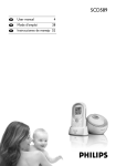
Welcome to the best generation of security with remote start. Your
system contains everything you need.
•
Responder LC remote control with SST technology for superior
range and reliability (p/n 7752V)
•
1-way Companion remote control (p/n 7654V)
•
AC adapter for charging your remote control (p/ n 8602T)
•
Documentation: Owner's guide and Warranty card
Your Warranty
Your Responder LC system comes with a warranty. Make sure you
receive the warranty registration cord and proof of purchase from your
dealer indicating the product was installed by on authorized Directed
dealer. Please validate it online at www.prodregister.com/ directed or
complete and return the warranty registration cord.
Getting Started
Due to transit and storage time prior to your purchase, the battery
charge may hove depleted. To ensure proper operation, check the
battery level and connect the battery charger if not fully charged.
The displayed battery level icon indicates when the battery is fully
charged.
Contents
Responder LC 2-Way........................................................................................... 2
Status Screen Icons .............................................................................................. 4
Using your System ............................................................................................... 7
Commands and Confirmations .............................................................. 7
Performing Commands ......................................................................... 7
Responder LC Command table .............................................................. 8
Fault Condition Alerts ........................................................................... 8
Basic Commands (Direct Access) .......................................................................... 9
Arm ................................................................................................... 9
Disarm ............................................................................................... 9
AUX/Trunk ........................................................................................ 10
Remote Start ...................................................................................... 10
Responder LC Configuration ............................................................................... 11
Navigating menus and options ............................................................ 11
Button operation ................................................................................ 11
Access menu items ............................................................................ 11
1-way Companion Remote Control ..................................................................... 12
Battery Information (Responder LC) ..................................................................... 13
Battery Information ( 1-Way) ................................................................ 13
Battery Disposal ................................................................................ 13
Government Regulations .................................................................................... 14
Warning! Safety First ......................................................................................... 16
Installation ........................................................................................ 16
Remote Start Capable ........................................................................ 16
Manual Transmission Vehicles ............................................................. 16
Interference ....................................................................................... 18
Upgrades and Batteries ...................................................................... 18
Water/Heat Resistance ...................................................................... 18
Limited lifetime consumer warranty ..................................................................... 19
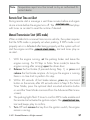
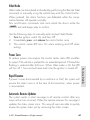
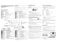
Responder LC 2-Woy
Internal
Antenna
Function Button
Used for transmitting and receivin
information
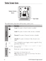
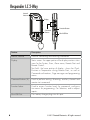
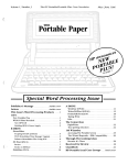
Status screen -the upper portion of the display contains status
icons for the System, Siren, Alarm zones, Remote Start and
Remote Control.
Text field - the lower portion of display - shows the Clock,
Runtime or Temperature during Remote Start, as well as
Command confirmations, Page messages and programming
Used to perform arming, disarming, auxiliary channel and
remote start commands
Used to access function levels for commands, configuration menus for programming, Car Selection, and to request
rt.
2
© 2012 Directed. All rights reserved.
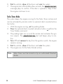
Control Center
N--++- Control button
The Control Center, typically located on the upper part of the front
windshield sends and receives commands or messages to and from
your system. It consists of:
The In-vehicle system antenna, for 2 way communication.
The Status LED, as a visual indicator of the system's status.
The Control button, for placing the system into Valet Mode* and
•
•
•
to perform the Emergency Override** operation.
* See "Remote and System Operations" in online guide.
**
See
"Alarm Features"
© 2012 Directed. All rights reserved.
in online guide.
3
........
St.......
ot'-liiiLIIus~S..........cr.___ee.JIILL.n.__..l.........
co.........,ns_ _ _ _ _ _ _ _ _ ·-----·~$X
• • •
t~ALL
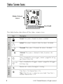
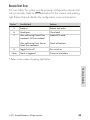
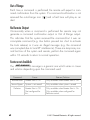
Status Screen
Icons
~1
:((
li
fwl lwlsiwl lwl IWI IWt
@ll!ff•IMf@) @I
w-+--- Text Field
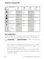
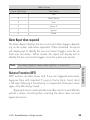
The table below describes all the status screen icons.
Armed: The system is Armed, the alarm is enabled.
{';:-~l.
''
'
Locked: The system is Locked in Valet, the alarm is disabled.
'''
I
'
Disarmed: The system is Disarmed, the alarm is disabled.
Unlocked: The system is Unlocked in Valet, the alarm is disabled.
en
:::)
R
en
c::
(I)
'-
V5
4
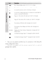
d
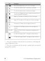
Siren is disabled for sensor triggers; remote is paged for all triggers (Sensor Silent Arm).
d +ALL
Siren is disabled for all triggers; remote is paged for all triggers
(Full Silent Arm).
:•, }
...
Remote start is active, the engine is running .
(~}
Timer Start is On; Remote Start is On.
Note: When the icon is without an arrow head: Timer Start is
enabled: Remote Start is Off
© 2012 Directed. All rights reserved.
{~)
+
I
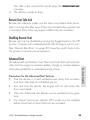
Smart Start is On ; Remote Start is On .
Note: When the icon is without an arrow head : Smart Start is
On ; Remote Start is Off.
1
Manual Transmission Start mode is enabled, the engine can
be started
I
Displays the vehicle interior temperature
§
On during Remote Start after performing the Defogger On
command
((Ill
On during Warn-away and Full Trigger message output
111
On during Trunk Zone Full Trigger output and Aux/Trunk
channel activation
On during Fault Report to indicate the Trunk is open and
bypassed when arming
cl)
.2
~
On during a Sensor Zone Full Trigger output
~
On during Fault Report to indicate a Sensor is active and
bypassed when arming
Iii
On during the Door Zone Full Trigger output
.Q
(/)
Q)
c
0
N
On during Fault Report to indicate a Door is open and
bypassed when arming
On during a Hood Zone Full Trigger output
On during Fault Report to indicate the Hood is open and
bypassed when arming
On when remote is set to command the system programmed
as Car 1 *
On when remote is set to command the system programmed
asCar2*
© 2012 Directed. All rights reserved.
5
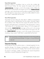
Bars indicate battery level is Full, 3/4, Y2, 114 or Empty
~
On while the remote control is transmitting a command
~
On while the remote control is receiving a message
•
•
X
•
On with Out of Range fault tone to indicate the remote failed to
receive a command confirmation
Pager on : The remote will wake up to listen for messages
Pager off: The remote will not wake up to listen for messages
The remote will Vibrate when messages are received
((
Text field
The remote will emit Beeps and Tones when messages are
received
Displays the Clock, Runtime, Temperature, message text and
feature menus
On after the Garage Open** message has been received .
On after the Garage Closed** message has been received.
*
This icon not present until the Car 2 is turned on in the Setup Re-
mote configuration menu.
* * This icon not present until the remote 1s paired with an optional
go rage door opener.
6
© 2012 Directed. All rights reserved.
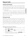
Commands and Confirmations
Commands, Basic or Advanced, are used to activate system features
and are performed by pressing one of the Command buttons. Basic
commands control the most often used security and remote start features while Advanced commands control more specialized features
and request reports.
Confirmations for Basic or Advanced commands are indicated
first by siren chirps and parking light flashes, and then by Text, Icons
and beeps or tones on the remote control. A description of each feature confirmation is found in the Basic Commands section. See online
guide for Advanced Commands section.
Performing Commands
Perform Basic commands by pressing one of the command buttons
while in the Direct Access level. Direct access is available while the
text field displays the Clock, Temperature or Runtime. Perform Advanced commands by first accessing one of the Function Levels and
then pressing one of the command buttons while within a level. Function Levels are available when the text field displays LEVEL 1,2,3 or
4.
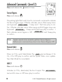
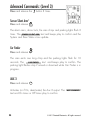
Advanced command example: Silent Arm
button once to access Function Level l, the text
l . Press the
field will display 'i;l ltllgi1JH .
button while '18111~%11& text is still on to perform the
2. Press the
f
tj
Silent Arm command.
3.
The Responder LC remote will display 'ff~Yitfllli:-}im? in the
text field and update the status screen icons.
© 2012 Directed. All rights reserved.
7
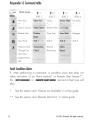
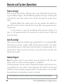
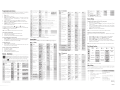
Responder LC Command table
Direct Access
lxl
lx2
lx3
lx4
LEVEL 3
LEVEL 4
Full Silent
Timer Start
Change Car
Remaining
(3s), Enter
programming
(8s)
Fault Condition Alerts
If, when performing a command, a condition exists that does not
allow activation of an Alarm feature* or Remote Start feature**,
the "~1111¥111111111 or 'zlllll.il'fiiiJIIIU text and a fault tone will
play.
8
*
See this section and //Feature not Available// in online guide.
**
See this section and //Remote Start Error// in online guide.
© 2012 Directed. All rights reserved.
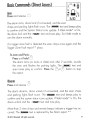
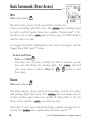
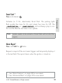
Arm
(01
Press and release D
The alarm arms, doors lock (if connected), and the siren
chirps and parking lights flash once. The ~-11% text and beeps play
to confirm and the System Status Icons update. If Valet mode* is On,
the doors lock and the u~0111//11:1~ text and tone play. Exit Valet mode to
arm the a Ia rm normally.
If a trigger zone fault is detected the siren chirps once again and the
Trigger Zone Fault report** plays.
To Arm and Panic rl5l
Press and hold D
The alarm Arms {or Locks in Valet} and, after 2 seconds, sounds
the siren and flashes the parking lights. The t!i~rlillllil~ text and
button to stop
siren tones play to confirm. Press the ~or
3
the output.
Disarm
~
Press and release ()
g-
The alarm disarms, doors unlock (if connected}, and the siren chirps
text and beeps play to
and parking lights flash twice. The
confirm and the system status icons update. If Valet mode* is On, the
doors unlock and the ;t:j~fll!llti1~; text and tone play.
More than 2 siren chirps and remote beeps indicate a trigger has occurred. The :~-~ text is replaced by the Alarm report.**
© 2012 Directed. All rights reserved.
9
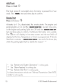
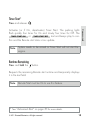
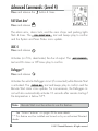
AUX/Trunk
Press and hold
8
The Trunk opens (if connected) when this button is pressed for 2 seconds. The >"IIUNII text and tones ploy to confirm.
Remote Start
Press and release ~~:}
Activates (or if On, deactivates) the remote starter. The engine and
parking lights turn On and the ~~WIIMDIII1111•tt:@"' text and tones ploy,
or the engine and parking lights turn Off and the ;>WIIIlfiii>B~Jlt:Jlff
text and tones ploy to confirm, the Remote Start status icons update.
The {:}icon will display in the status screen and the text field will
display the Runtime, Temperature or Clock as programmed. If Remote
Start foils to activate,
ss'llflfi11WIIiltvlllfll7t> text and
a fault tone ploy
while the parking lights flash to identify the reason.***
*
See
"Remote and System Operations" in on-~~e gu~e.-----------------1
I **
See
''Alarm Features"
j
J
in online guide.
;
* * * See "Remote Start Error" in online guide.
;
I ~~:~~~~~~~~~;m~~~;;_ vehic~es~:"~a:~ T==~~:::_:~~~:_:
10
© 2012 Directed. All rights reserved.
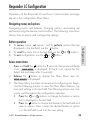
Responder LC Configuration
The Responder LC can be customized through the Main Menu. Configurable feature details can be found in the expanded online guide.
Navigating menus and options
Navigating menus and features, changing options, and exiting are
performed using the remote control buttons. The following instructions
discuss how to access and configure the settings.
BuHon operation
•
To access menus, set options, and to perform actions that are
displayed in the text field, use the
button.
To scroll the menu lists in the text fiel~se the
buttons.
To exit configuration: use the
or ()buttons.
f
•
•
eJ
Access menu items
1.
2.
f
Press and hold the
button for 8 seconds, the remote will beep
once, r:::leM!:Iti[JI. ;r is displayed. (If Car 2 is on, ignore the Car
Select text and beep after 3 seconds}.
Release the
button to display the Main Menu item list,
-~y- -·· -· -· · · · :-· . . . ,. .,. . ,. . . ,. .,...•: is dis Ia ed.
f
p y
·. "· .;. . . ,. . -~. ,. . . . . . . . . . _. . . . . . . .'I'
3.
8& {:)
The Main Menu has been accessed and configuring can begin.
Use the following process to view the Main Menu features, options and settings in the text field. The following actions are commonly used throughout the configuration operation.
•
Press the
or {:) buttons to change the feature or option
that is displayed in the text field.
•
Press the
button to choose the feature in the text field and
view its options. Press it when the desired feature or option
8
f
is in the text field to set it as the new setting.
© 2012 Directed. All rights reserved.
11
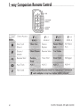
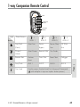
1-woy Companion Remote Control
--+f--1H-*-l
Direct Access
Command
Buttons
/x2
/x4
LEVEL 4
Full Silent
Arm/Lock
(Panic)
Disarm/
Unlock
Remote Start
Timer Start
Defogger
Aux/Trunk
Not Used
12
© 2012 Directed. All rights reserved.
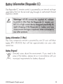
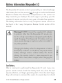
Battery Information (Responde£ LC)
The Responder LC remote control is powered by on internal rechargeable battery that con be serviced
g_o_Gt through on authorized Directed
Electronics dealer.
BaHery Information (1-Way)
1way companion remote is powered by one 3V coin cell lithium
battery (PN CR-2032) that will last approximately one year under
The
normal use.
Battery Disposal
Directed cores about the environment. If you need to dispose of the battery, please do so in accordance with your
municipal requirements for battery disposal.
© 2012 Directed. All rights reserved.
13
This product is covered
by one
or more of the following United States
patents:
Remote Start Patents:
5,349,931; 5,872,519; 5,914,667; 5,952,933; 5,945,936;
5,990,786; 6,028,372; 6,467,448; 6,561,151; 7,191,053;
7,483,783
Vehicle Security Patents:
5,467,070; 5,532,670; 5,534,845; 5,563,576; 5,646,591;
5,650,774; 5,673,017; 5,712,638; 5,872,519; 5,914,667;
5,952,933; 5,945,936; 5,990,786; 6,028,505; 6,452,484
Other patents pending.
Gmternment!egulotions .
This device complies with Part 15 of FCC rules . Operation is subject to the following two conditions: ( 1) This device may not cause harmful interference, and
(2) This device must accept any interference received, including interference
that may cause undesirable operation.
This equipment has been tested and found to comply with the limits for a class B
digital device, pursuant to Part 15 of the FCC Rules . These limits are designed
to provide reasonable protection against harmful interference in a residential
installation . This equipment generates and can radiate radio frequency energy and , if not installed and used in accordance with the instruction manual,
may cause harmful interference to radio communications. However, there is
no guarantee that interference will not occur in a particular installation. If this
equipment does cause harmful interference to radio or television, which can be
14
© 2012 Directed. All rights reserved.
determined by turning the equipment OFF and ON, the user is encouraged to
try to correct the interference by one or more of the following measures:
• Reorient or relocate the receiving antenna.
• Increase the separation between the equipment and receiver.
• Connect the equipment into on outlet on a circuit different from that to which
the receiver is connected.
• Consult the dealer or on experienced radio /TV technician for help.
Remote Controls
To satisfy FCC RF exposure compliance requirements, this device should be
used in hand-held, hand operated configurations only. The device and its antenna must maintain a separation distance of 20 em or more from the person's
body, except for the hand and wrists, to satisfy RF exposure compliance. This
device is designed to be used in a person's hands and its operating configurations do not support normal transmissions while it is carried in pockets or
holsters next to a person's body.
Control Center
To satisfy FCC RF exposure compliance requirements, the device and its antenna must maintain a separation distance of 20 em or more from the person's
body, except for the hand and wrists, to satisfy RF exposure compliance.
This device complies with the Industry Canada Radio Standards Specification
RSS 210. Its use is authorized only on a no-interference, no-protection basis;
in other words, this device must not be used if it is determined that it causes
harmful interference to services authorized by IC. In addition, the user of this
device must accept any radio interference that may be received, even if this
interference could affect the operation of the device.
WARNING! Changes or modifications not expressly approved by the party
responsible for compliance could void the user's authority to operate this device.
© 2012 Directed. All rights reserved.
15
Warning! Safety First____
'1\
~
Please read the safety warnings below before proceeding. Improper
use of the product may be dangerous or illegal.
Installation
Due to the complexity of this system, installation of this product must only be
performed by an authorized Directed dealer. If you have any questions, ask
your retailer or contact Directed directly at
l-800-753-0600.
Remote Start Capable
When properly installed, this system can start the vehicle via a command
signal from the remote control transmitter. Therefore, never operate the system
in an enclosed area or partially enclosed area without ventilation (such as a
garage). When parking in an enclosed or partially enclosed area or when
having the vehicle serviced, the remote start system must be disabled using the
installed menu wheel. It is the user's sole responsibility to properly handle and
keep out of reach from children all remote control transmitters to assure that the
system does not unintentionally remote start the vehicle. THE USER MUST INSTALL A CARBON MONOXIDE DETECTOR IN OR ABOUT THE LIVING AREA
ADJACENT TO THE VEHICLE. ALL DOORS LEADING FROM ADJACENT LIVING AREAS TO THE ENCLOSED OR PARTIALLY ENCLOSED VEHICLE STORAGE AREA MUST AT ALL TIMES REMAIN CLOSED. These precautions are the
sole responsibility of the user.
Manual Transmission Vehicles
Remote starters on manual transmission vehicles operate differently than those
with automatic transmission because you must leave your car in neutral. You
must read this Owner's Guide to familiarize yourself with the proper procedures
regarding manual transmission remote starters. If you have any questions, ask
your authorized Directed dealer or contact Directed at
16
l-800-753-0600.
© 2012 Directed. All rights reserved.
Before remote starting a manual transmission vehicle, be sure to :
•
Leave the vehicle in neutral and be sure no one is standing in front or
behind the vehicle.
•
Only remote start on a flat surface
•
Hove the parking broke fully engaged
WARNING! It is the responsibility of the owner to ensure the parking/ emergency broke properly functions. Failure to do so con result in personal injury or
property damage. We recommend the owner hove the parking /emergency
broke system inspected and adjusted by a qualified automotive shop biannually.
Use of this product in a manner contrary to its intended mode of operation may
result in property damage, personal injury, or death. ( 1) Never remotely start
the vehicle with the vehicle in gear, and (2) Never remotely start the vehicle
with the keys in the ignition. The user must also hove the neutral safety feature
of the vehicle periodically checked, wherein the vehicle must not remotely start
while the cor is in gear. This testing should be performed by an authorized
Directed dealer in accordance with the Safety Check outlined in the product
installation guide. If the vehicle starts in gear, cease remote start operation immediately and consult with the authorized Directed dealer to fix the problem .
After the remote start module has been installed, contact your authorized dealer
to hove him or her test the remote start module by performing the Safety Check
outlined in the product installation guide. If the vehicle starts when performing
the Neutral Safety Shutdown Circuit test, the remote start unit has not been
properly installed. The remote start module must be removed or the installer
must properly reinstall the remote start system so that the vehicle does not start
in gear. All installations must be performed by on authorized Directed dealer.
OPERATION OF THE REMOTE START MODULE IF THE VEHICLE STARTS IN
© 2012 Directed. All rights reserved.
17
GEAR IS CONTRARY TO ITS INTENDED MODE OF OPERATION. OPERATING THE REMOTE START SYSTEM UNDER THESE CONDITIONS MAY
RESULT IN PROPERTY DAMAGE OR PERSONAL INJURY. YOU MUST IMMEDIATELY CEASE THE USE OF THE UNIT AND SEEK THE ASSISTANCE OF AN
AUTHORIZED Directed DEALER TO REPAIR OR DISCONNECT THE INSTALLED
REMOTE START MODULE. DIRECTED WILL NOT BE HELD RESPONSIBLE OR
PAY FOR INSTALLATION OR REINSTALLATION COSTS.
This product is designed for fuel injected vehicles only. Use of this
product in a standard transmission vehicle must be in strict accordance
with this guide.
This product should not be installed in any convertible vehicles, soft or
hard top with a manual transmission. Installation in such vehicles may
pose certain risk.
Interference
All radio devices are subject to interference which could affect proper
performance .
Upgrades and Batteries
Any upgrades to this product and/ or installation of batteries must be
performed by an authorized dealer. Do not attempt to perform any
unauthorized modifications to this product.
Water/Heat Resistance
This product is not designed to be water and/ or heat-resistant. Please
take care to keep this product dry and away from heat sources. Any
damage from water or heat will void the warranty.
18
© 2012 Directed. All rights reserved.
Limited lifetime consumer wouooty
Directed Electronics. ("Directed") promises to the original purchaser to repair or replace
(at Directed's election) with a comparable reconditioned model any Directed unit (hereafter the "unit"), excluding without limitation the siren, the remote transmitters, the associated
sensors and accessories, which proves to be defective in workmanship or material under
reasonable use during the lifetime of the vehicle provided the following conditions are met:
the unit was purchased from an authorized Directed dealer, the unit was professionally
installed and serviced by an authorized Directed dealer; the unit will be profession•ally
reinstalled in the vehicle in which it was originally installed by an authorized Directed
dealer; and the unit is returned to Directed, shipping prepaid with a legible copy of the
bill of sale or other dated proof of purchase bearing the following information: consumer's
name, telephone number and address; the authorized dealers name, telephone number
and address; complete product description, including accessories; the year, make and
model of the vehicle; vehicle license number and vehicle identification number. All components other than the unit, including without limitation the siren, the remote transmitters
and the associated sensors and accessories, carry a one-year warranty from the date of
purchase of the same. ALL PRODUCTS RECEIVED BY DIRECTED FOR WARRANTY REPAIR
WITHOUT PROOF OF PURCHASE FROM AN AUTHORIZED DEALER WILL BE DENIED.
This warranty is non-transferable and is automatically void if: the unit's date code or serial
number is defaced, missing or altered; the unit has been modified or used in a manner
contrary to its intended purpose; the unit has been damaged by accident, unreasonable
use, neglect, improper service, installation or other causes not arising out of defects in
materials or construction . The warranty does not cover damage to the unit caused by
installation or removal of the unit. Directed, in its sole discretion, will determine what constitutes excessive damage and may refuse the return of any unit with excessive damage.
TO THE MAXIMUM EXTENT ALLOWED BY LAW, ALL WARRANTIES, INCLUDING
BUT NOT LIMITED TO EXPRESS WARRANTY, IMPLIED WARRANTY, WARRANTY
OF MERCHANTABILITY, FITNESS FOR PARTICULAR PURPOSE AND WARRANTY OF
NON-INFRINGEMENT OF INTELLECTUAL PROPERTY, ARE EXPRESSLY EXCLUDED;
AND DIRECTED NEITHER ASSUMES NOR AUTHORIZES ANY PERSON OR ENTITY
TO ASSUME FOR IT ANY DUTY, OBLIGATION OR LIABILITY IN CONNECTION
WITH ITS PRODUCTS. DIRECTED DISCLAIMS AND HAS ABSOLUTELY NO LIABILITY
FOR ANY AND ALL ACTS OF THIRD PARTIES INCLUDING ITS AUTHORIZED
DEALERS OR INSTALLERS. DIRECTED SECURITY SYSTEMS, INCLUDING THIS UNIT,
ARE DETERRENTS AGAINST POSSIBLE THEFT. DIRECTED IS NOT OFFERING A
GUARANTEE OR INSURANCE AGAINST VANDALISM, DAMAGE OR THEFT OF THE
AUTOMOBILE, ITS PARTS OR CONTENTS; AND HEREBY EXPRESSLY DISCLAIMS ANY
LIABILITY WHATSOEVER, INCLUDING WITHOUT LIMITATION, LIABILITY FOR THEFT,
DAMAGE AND/OR VANDALISM. THIS WARRANTY DOES NOT COVER LABOR
COSTS FOR MAINTENANCE, REMOVAL OR REINSTALLATION OF THE UNIT OR
© 2012 Directed. All rights reserved.
19
ANY CONSEQUENTIAL DAMAGES OF ANY KIND. IN THE EVENT OF A CLAIM
OR A DISPUTE INVOLVING DIRECTED OR ITS SUBSIDIARY, THE VENUE SHALL BE
SAN DIEGO COUNTY IN THE STATE OF CALIFORNIA. CALIFORNIA STATE LAWS
AND APPLICABLE FEDERAL LAWS SHALL APPLY AND GOVERN THE DISPUTE. THE
MAXIMUM RECOVERY UNDER ANY CLAIM AGAINST DIRECTED SHALL BE STRICTLY
LIMITED TO THE AUTHORIZED DIRECTED DEALER'S PURCHASE PRICE OF THE UNIT.
DIRECTED SHALL NOT BE RESPONSIBLE FOR ANY DAMAGES WHATSOEVER,
INCLUDING BUT NOT LIMITED TO, ANY CONSEQUENTIAL DAMAGES, INCIDENTAL
DAMAGES, DAMAGE TO VEHICLE, DAMAGES FOR THE LOSS OF TIME, LOSS OF
EARNINGS, COMMERCIAL LOSS, LOSS OF ECONOMIC OPPORTUNITY AND THE
LIKE. NOTWITHSTANDING THE ABOVE, THE MANUFACTURER DOES OFFER A
LIMITED WARRANTY TO REPLACE OR REPAIR THE CONTROL MODULE SUBJECT TO
THE CONDITIONS AS DESCRIBED HEREIN. THIS WARRANTY IS VOID IF THE UNIT
HAS NOT BEEN PURCHASED FROM DIRECTED, OR AN AUTHORIZED DIRECTED
DEALER, OR IF THE UNIT HAS BEEN DAMAGED BY ACCIDENT, UNREASONABLE
USE, NEGLIGENCE, ACTS OF GOD, NEGLECT, IMPROPER SERVICE, OR OTHER
CAUSES NOT ARISING OUT OF DEFECT IN MATERIALS OR CONSTRUCTION.
Some states do not allow limitations on how long an implied warranty will last or the
exclusion or limitation of incidental or consequential damages. This warranty gives you
specific legal rights and you may also have other rights that vary from State to State.
This warranty is only valid for sale of product(s) within the United States of America and
in Canada. Product(s) sold outside of the United States of America or Canada are sold
"AS-IS" and shall have NO WARRANTY, express or implied.
For further details relating to warranty information of Directed products, please visit the
support section of Directed's website at: www.directed.com
This product may be covered by a Guaranteed Protection Plan ("GPP"). See your
authorized Directed dealer for details of the plan or call Directed Customer Service at
1-800-876-0800.
9 20- 100 1 1-0 1 20 1 1-06
20
© 2012 Directed. All rights reserved.
DIRECTED*
The company behind Viper® Auto Security
Systems is Directed.
Since its inception, Directed has had one purpose, to provide consumers with the finest
vehicle security and car stereo products and
accessories available. The recipient of nearly
100 patents and Innovations Awards in the
field of advanced electronic technology.
Quality Directed products are sold and serviced throughout North America and around
the world.
Call (800) 876-0800 for more information
about our products and services.
© 2012 Directed. All rights reserved.
Vista, CA 92081
www.viper.com
ORG5704VML 2012-08
M
OWNER'S
GUIDE
0
0
E
5704
L
Congratulations
Congratulations on the purchase of your state-of-the-art security and
remote start system. Reading this Owner’s Guide prior to using your
system will help maximize the use of your system and its many features. Please visit: www.viper.com – For general and additional guide
information. For any additional questions please contact your authorized Directed dealer or contact Directed at 1-800-753-0600.
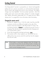
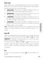
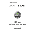
What you get
Welcome to the best generation of security with remote start. Your
system contains everything you need.
s
s
s
s
Responder LC remote control with SST technology for superior
range and reliability
1-way Companion remote control
AC adapter for charging your remote control
Owner’s guide and Warranty card
er’s
Own e
Guid
AUX
Warranty
Card
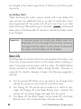
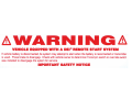
Important information
Government Regulations and Safety information
Read the Government Regulations and Warning! Safety
First sections of this manual prior to operating this system.
Warning! Failure to heed this information can result in
death, personal injury or property damage and may also
result in the illegal use of the system beyond its intended
purpose.
Your Warranty
Your Responder LC system comes with a warranty. Please make sure
you receive the warranty registration card and proof of purchase from
your dealer indicating the product was installed by an authorized
Directed dealer. Please validate it online at www.prodregister.com/
directed or complete and return the warranty registration card.
Replacement remote controls
If additional remote controls are desired, please see your authorized
dealer or visit us at www.directedstore.com to order. Part numbers
are: 7752V for Responder LC 2-way remote control and 7652V for
the companion remote control. Your system can also be used with
optional Responder HD color 2-way remote control (7941V).
Contents
Getting Started.................................................................................................... 4
Charging the remote control:................................................................. 4
Keys to using this manual...................................................................... 5
Responder LC 2-Way........................................................................................... 6
Status Screen Icons .............................................................................................. 8
Using your System ............................................................................................. 11
Commands and Confirmations ............................................................ 11
Performing Commands ....................................................................... 11
Responder LC Command table ............................................................ 12
Fault Condition Alerts ......................................................................... 12
Basic commands (Direct Access) ......................................................................... 14
Arm ................................................................................................. 14
Disarm ............................................................................................. 14
AUX/Trunk........................................................................................ 15
Remote Start...................................................................................... 15
Advanced commands: (Level 1) .......................................................................... 16
Silent Arm ......................................................................................... 16
AUX 1 .............................................................................................. 16
Runtime Reset .................................................................................... 17
Temp Request .................................................................................... 17
Advanced commands: (Level 2) .......................................................................... 18
Sensor Bypass ................................................................................... 18
Remote Valet .................................................................................... 18
AUX 2 .............................................................................................. 18
Timer Start ........................................................................................ 19
Runtime Remaining ............................................................................ 19
Advanced commands: (Level 3) .......................................................................... 20
Sensor Silent Arm .............................................................................. 20
AUX 3 .............................................................................................. 20
Smart Start ........................................................................................ 21
Alarm Report..................................................................................... 21
Advanced commands: (Level 4) .......................................................................... 22
Full Silent Arm ................................................................................... 22
AUX 4 .............................................................................................. 22
Defogger .......................................................................................... 22
Responder LC configuration ............................................................................... 23
Navigating menus and options ............................................................ 23
Button operation ................................................................................ 23
Access menu items ............................................................................ 23
Main Menu ....................................................................................................... 24
Setup Remote menu:........................................................................... 24
Remote Start Info ............................................................................... 25
Runtime Alert..................................................................................... 26
Car 2 ............................................................................................... 26
Screen Color ..................................................................................... 26
Temp Unit ......................................................................................... 26
Button Beep....................................................................................... 27
System Type ...................................................................................... 27
Clock Set .......................................................................................... 27
Review ............................................................................................. 27
Exit .................................................................................................. 27
Sensor Adjust: ................................................................................... 27
Pair Remote:...................................................................................... 28
Demo mode: ..................................................................................... 28
Power Off: ........................................................................................ 29
Exit: ................................................................................................. 29
Alarm Features ................................................................................................. 30
Normal Arm Protection ....................................................................... 30
Sensor Silent Arm protection ............................................................... 30
Full Silent Arm Protection .................................................................... 31
Sensor Warn-away Messages ............................................................. 31
Full Trigger Messages ......................................................................... 31
Emergency Override .......................................................................... 31
Trigger Zone Fault Report.................................................................... 32
Alarm Report when disarming ............................................................. 32
Alarm Report when requested ............................................................. 33
Nuisance Prevention (NPC) ................................................................. 33
Remote Start Features ........................................................................................ 34
Pit Stop Mode ................................................................................... 34
Key Takeover..................................................................................... 34
Remote Start Safe-lock ........................................................................ 35
Disabling Remote Start ....................................................................... 35
Advanced Start ................................................................................. 35
Temperature Reporting........................................................................ 36
Remote Start Time-out Alert.................................................................. 37
Manual Transmission Start (MTS mode) ................................................ 37
Turbo Timer Mode.............................................................................. 38
Remote Start Error .............................................................................. 39
Remote and System Operations .......................................................................... 40
Passive Arming .................................................................................. 40
Auto Re-arming.................................................................................. 40
Valet Mode ....................................................................................... 41
Power Save....................................................................................... 41
Rapid Resume ................................................................................... 41
Automatic Remote Updates ................................................................. 41
Out of Range .................................................................................... 42
No Remote Output ............................................................................. 42
Feature not Available ......................................................................... 42
1-way Companion Remote Control ..................................................................... 43
Accessing Commands ........................................................................ 44
Button Auto Lock ................................................................................ 44
Car Select ......................................................................................... 44
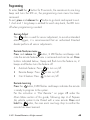
Programming .................................................................................... 45
Battery Information (1-Way) ................................................................ 46
System Expansion Options ................................................................................. 47
Battery Information (Responder LC) ..................................................................... 49
Low Battery ....................................................................................... 49
Battery Life ........................................................................................ 50
Battery Disposal ................................................................................ 51
Glossary of Terms.............................................................................................. 52
Government Regulations .................................................................................... 54
Warning! Safety First ......................................................................................... 56
Installation ........................................................................................ 56
Remote Start Capable ........................................................................ 56
Manual Transmission Vehicles ............................................................. 56
Interference ....................................................................................... 58
Upgrades and Batteries ...................................................................... 58
Water/Heat Resistance ...................................................................... 58
Limited lifetime consumer warranty ..................................................................... 59
Getting Started
Your Responder LC remote is powered by an internal rechargeable
battery that can only be serviced by an authorized Directed dealer.
Due to transit and storage time prior to your purchase, the battery
charge may have depleted. To ensure proper operation, check the
battery level and connect the battery charger if not fully charged.
See “Battery Information (Responder LC)” on page 49 and “Status
Screen Icons” on page 8 for more information about the battery.
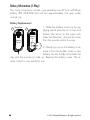
Charging the remote control:
1.
2.
3.
Plug the AC adapter into a 110V AC outlet. Insert the mini-USB
connector into the mini-USB port located on the side of the
remote control (see diagram under Responder LC 2-way). The
text field will display CHARGE to indicate the remote control is
charging (The remote remains operational while charging and
can command the system).
Once fully charged the text field will display FULL .
The remote control is then ready for use. Disconnect the miniUSB end from the remote control first and then the AC adapter
from the AC outlet.
Note
4
If the battery is excessively depleted when the charger is
connected, functionality may be delayed while it charges to
the minimum voltage required to operate the display, after
which normal charging resumes.
© 2011 Directed Electronics. All rights reserved.
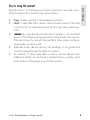
Keys to using this manual
At a Glance
Specific actions (in bold type) and style conventions are used consistently throughout this manual, they are as follows:
s
s
s
s
s
Press: implies pushing in and releasing a button.
Hold: is used after Press actions when a button needs to be held
in position for an extended period of time, typically several seconds.
ARMED this style denotes the text which appears in the text field
portion of the Display during operations described in the manual.
If the text string is too long for the text field, it then plays and loops
sequentially word by word.
Italicized words denote section/sub headings in this guide and
can be located through the table of contents.
An asterisk (*) when used after a word or phrase denotes that
additional details can be found in related sections usually noted
at the bottom of the page or end of the section.
© 2011 Directed Electronics. All rights reserved.
5
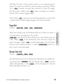
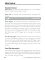
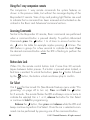
Responder LC 2-Way
Internal
Antenna
Display
Command
Buttons
6
Function Button
Mini-USB Port
Feature
Description
Internal Antenna
Used for transmitting and receiving information
Display
Status screen - the upper portion of the display contains status
icons for the System, Siren, Alarm zones, Remote Start and
Remote Control.
Text field - the lower portion of display - shows the Clock,
Runtime or Temperature during Remote Start, as well as
Command confirmations, Page messages and programming
menus
Command buttons (4)
Used to perform arming, disarming, auxiliary channel and
remote start commands
Function button
Used to access function levels for commands, configuration menus for programming, Car Selection, and to request
reports.
Mini-USB Port
The battery charger plugs into this port.
© 2011 Directed Electronics. All rights reserved.
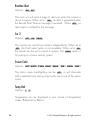
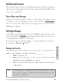
Control Center
At a Glance
Status LED
Control button
The Control Center, typically located on the upper part of the front
windshield sends and receives commands or messages to and from
your system. It consists of:
s
s
s
The In-vehicle system antenna, for 2 way communication.
The Status LED, as a visual indicator of the system’s status.
The Control button, for placing the system into Valet Mode* and
to perform the Emergency Override** operation.
* See “Remote and System Operations” on page 40 for details.
** See “Alarm Features” on page 30 for details.
© 2011 Directed Electronics. All rights reserved.
7
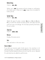
Status Screen Icons
Status Screen
Icons
ALL
1
Text Field
The table below describes all the status screen icons.
Icon
Description
System Status
Armed: The system is Armed, the alarm is enabled.
Locked: The system is Locked in Valet, the alarm is disabled.
Disarmed: The system is Disarmed, the alarm is disabled.
Remote Start
Siren Status
Unlocked: The system is Unlocked in Valet, the alarm is disabled.
8
Siren is disabled for sensor triggers; remote is paged for all triggers (Sensor Silent Arm).
+ ALL
Siren is disabled for all triggers; remote is paged for all triggers
(Full Silent Arm).
Remote start is active, the engine is running.
Timer Start is On; Remote Start is On.
Note: When the icon is without an arrow head: Timer Start is
enabled: Remote Start is Off
© 2011 Directed Electronics. All rights reserved.
Icon
Remote Start
At a Glance
+
Description
Smart Start is On; Remote Start is On.
Note: When the icon is without an arrow head: Smart Start is
On; Remote Start is Off.
Manual Transmission Start mode is enabled, the engine can
be started
Displays the vehicle interior temperature
On during Remote Start after performing the Defogger On
command
On during Warn-away and Full Trigger message output
On during Trunk Zone Full Trigger output and Aux/Trunk
channel activation
On during Fault Report to indicate the Trunk is open and
bypassed when arming
Zone Status
On during a Sensor Zone Full Trigger output
On during Fault Report to indicate a Sensor is active and
bypassed when arming
On during the Door Zone Full Trigger output
On during Fault Report to indicate a Door is open and
bypassed when arming
On during a Hood Zone Full Trigger output
On during Fault Report to indicate the Hood is open and
bypassed when arming
On when remote is set to command the system programmed
as Car 1*
On when remote is set to command the system programmed
as Car 2*
© 2011 Directed Electronics. All rights reserved.
9
Icon
Description
Bars indicate battery level is Full, ¾,½,¼ or Empty
On while the remote control is transmitting a command
On while the remote control is receiving a message
Remote Control Status
On with Out of Range fault tone to indicate the remote failed to
receive a command confirmation
Pager on: The remote will wake up to listen for messages
Pager off: The remote will not wake up to listen for messages
The remote will Vibrate when messages are received
The remote will emit Beeps and Tones when messages are
received
Text field
Displays the Clock, Runtime, Temperature, message text and
feature menus
On after the Garage Open** message has been received.
On after the Garage Closed** message has been received.
* This icon not present until the Car 2 is turned on in the Setup Remote configuration menu.
** This icon not present until the remote is paired with an optional
garage door opener.
10
© 2011 Directed Electronics. All rights reserved.
Using your System
Commands and Confirmations
Performing Commands
Perform Basic commands by pressing one of the command buttons
while in the Direct Access level. Direct access is available while the
text field displays the Clock, Temperature or Runtime. Perform Advanced commands by first accessing one of the Function Levels and
then pressing one of the command buttons while within a level. Function Levels are available when the text field displays LEVEL 1,2,3 or
4.
Advanced command example: Silent Arm
1. Press the
button once to access Function Level 1, the text
field will display LEVEL 1 .
2. Press the
button while LEVEL 1 text is still on to perform the
Silent Arm command.
3. The Responder LC remote will display SILENT ARMED in the
text field and update the status screen icons.
© 2011 Directed Electronics. All rights reserved.
11
Commands
Commands, Basic or Advanced, are used to activate system features
and are performed by pressing one of the Command buttons. Basic
commands control the most often used security and remote start features while Advanced commands control more specialized features
and request reports.
Confirmations for Basic or Advanced commands are indicated
first by siren chirps and parking light flashes, and then by Text, Icons
and beeps or tones on the remote control. A description of each
feature confirmation is found in the following Basic command and
Advanced command sections.
Responder LC Command table
Level
Direct Access
Button
x1
LEVEL 1
Arm/Lock
Silent Arm
(Panic)
x2
LEVEL 2
x3
LEVEL 3
x4
LEVEL 4
Sensor
Sensor Silent
Full Silent
Bypass
Arm
Arm
Disarm/Unlock
Silent Disarm
Remote Valet
Car Finder
Remote Start
Runtime
Timer Start
Smart Start
Defogger
AUX 4
Reset
AUX
Aux/Trunk
AUX 1
AUX 2
AUX 3
Advance Level
Temperature
Runtime
Alarm
Change Car
Check
Remaining
Report
(3s), Enter
programming
(8s)
Fault Condition Alerts
If, when performing a command, a condition exists that does not
allow activation of an Alarm feature* or Remote Start feature**,
the NOT AVAILABLE or REMOTE START ERROR text and a fault tone will
play.
*
12
Alarm feature not available when the system status is incorrect
upon receiving the command. (Example: Sensor bypass command is received when disarmed).
Refer to the notes included in the following command descriptions
that address these faults or go to “Feature not Available” on page
42 for more details.
© 2011 Directed Electronics. All rights reserved.
** Remote Start feature not available when the Remote Start status is
incorrect upon receiving the command. (Example: Runtime reset
command received when remote start is off)
Refer to the notes included in the command descriptions that address these faults or go to “Remote Start Error” on page 39
for more details.
Commands
© 2011 Directed Electronics. All rights reserved.
13
Basic Commands (Direct Access)
Arm
Press and release
6:30
The alarm arms, doors lock (if connected), and the siren
chirps and parking lights flash once. The ARMED text and beeps play
to confirm and the System Status Icons update. If Valet mode* is On,
the doors lock and the VALET text and tone play. Exit Valet mode to
arm the alarm normally.
If a trigger zone fault is detected the siren chirps once again and the
Trigger Zone Fault report** plays.
To Arm and Panic
Press and hold
The alarm Arms (or Locks in Valet) and, after 2 seconds, sounds
the siren and flashes the parking lights. The PANIC text and
siren tones play to confirm. Press the
or
button to stop
the output.
Disarm
Press and release
The alarm disarms, doors unlock (if connected), and the siren chirps
and parking lights flash twice. The DISARM text and beeps play to
confirm and the system status icons update. If Valet mode* is On, the
doors unlock and the VALET text and tone play.
More than 2 siren chirps and remote beeps indicate a trigger has occurred. The DISARM text is replaced by the Alarm report.**
14
© 2011 Directed Electronics. All rights reserved.
AUX/Trunk
Press and hold
AUX
Remote Start
Press and release
Activates (or if On, deactivates) the remote starter. The engine and
parking lights turn On and the REMOTE START ON text and tones play,
or the engine and parking lights turn Off and the REMOTE START OFF
text and tones play to confirm, the Remote Start status icons update.
The
icon will display in the status screen and the text field will
display the Runtime, Temperature or Clock as programmed. If Remote
Start fails to activate, REMOTE START ERROR text and a fault tone play
while the parking lights flash to identify the reason.***
*
See “Remote and System Operations” on page 40 for details.
** See “Alarm Features” on page 30 for details.
*** See “Remote Start Error” on page 39 for details.
For Manual transmission vehicles see “Manual Transmission Start (MTS
mode)” on page 37 for more details.
© 2011 Directed Electronics. All rights reserved.
15
Commands
The Trunk opens (if connected) when this button is pressed for 2 seconds. The TRUNK text and tones play to confirm.
Advanced Commands: (Level 1)
Press and release the
button 1 time.
level 1
Silent Arm
Press and release
The alarm arms, doors lock (if connected), and the parking lights flash
once. The SILENT ARMED text plays to confirm and the System Status
icons update. Valet mode* or Trigger Zone Fault report** messages
may be received.
Silent Disarm
Press and release
The alarm disarms, doors unlock (if connected), and the parking lights
flash twice. The SILENT DISARM text plays to confirm and the System
Status icons update. The Alarm report** may replace the Silent Disarm text.
AUX 1
Press and release
AUX
Activates (or if On, deactivates) the Aux 1 output. The
text and On tones or Off tones play to confirm.
16
AUX CHANNEL
© 2011 Directed Electronics. All rights reserved.
Runtime Reset
Press and release
Note
Remote Start must be On to use this feature.
Temp Request
Press and hold the
button
Requests the vehicle’s interior temperature and temporarily displays it
via status screen icon
and text field.
* See “Remote and System Operations” on page 40 for details.
** See “Alarm Features” on page 30 for details.
© 2011 Directed Electronics. All rights reserved.
17
Commands
If more time is needed while remote start is active, runtime reset
will reset the runtime counter to the pre-programmed setting. The
RUNTIME
text and tones play to confirm. The text field will update
if set to display runtime.
Advanced Commands: (Level 2)
Press and release the
button 2 times.
Sensor Bypass
level 2
Press and release
The parking lights flash each time this command is received to indicate
the Sensor bypass type. 2 flashes indicates sensor Warn-away zones
are bypassed. BYPASS WARN , 1 beep and 1 fault tone play to confirm. 3 flashes indicates sensor Warn-away and Full Trigger zones are
bypassed. BYPASS FULL , 1 beep and 2 fault tone play to confirm. 1
flash indicates sensor bypass is Off, BYPASS OFF and 1beep play
to confirm..
Note
System needs to be armed to perform Sensor Bypass.
Perform arm command any time to turn Sensor Bypass Off.
Remote Valet
Press and release
Enters (or if On, exits) Valet Mode. The VALET text and beeps (1 for
On, 2 for Off) play to confirm and the System Status icons update.
See Valet Mode for more details
AUX 2
Press and release
AUX
Activates (or if On, deactivates) the Aux 2 output. The
text and On tones or Off tones play to confirm.
18
AUX CHANNEL
© 2011 Directed Electronics. All rights reserved.
Timer Start*
Press and release
Note
System needs to be armed or Timer Start will not start the
engine.
Runtime Remaining
Press and hold the
button
Requests the remaining Remote start runtime and temporarily displays
it in the text field.
Note
Remote Start must be On to use this feature.
* See “Advanced Start” on page 35 for more details.
© 2011 Directed Electronics. All rights reserved.
19
Commands
Activates (or if On, deactivates) Timer Start. The parking lights
flash quickly four times for On and slowly four times for Off. The
TIMER START ON
or TIMER START OFF text and beeps play to confirm and the Remote start status icons update.
Advanced Commands: (Level 3)
Press and release the
button 3 times.
level 3
Sensor Silent Arm*
Press and release
The alarm arms, doors lock, the siren chirps and parking lights flash 3
times. The SENSOR SILENT ARM text and beeps play to confirm and the
System and Siren Status icons update.
Car finder
Press and release
The siren emits one long chirp and the parking lights flash for 10
CAR FINDER
seconds. The
text and beeps play to confirm. The
parking light flashes stop if armed or disarmed while Car Finder is in
progress.
AUX 3
Press and release
AUX
Activates (or if On, deactivates) the Aux 3 output. The
text and On tones or Off tones play to confirm.
20
AUX CHANNEL
© 2011 Directed Electronics. All rights reserved.
Smart Start**
Press and release
Note
System needs to be armed or Smart Start will not start the
engine.
Alarm Report*
Press and hold the
button
Requests a report of the most recent triggers and temporarily displays it
in the text field. The report clears when the ignition is turned on.
* See “Alarm Features” on page 30 for more details.
** See “Advanced Start” on page 35 for more details.
© 2011 Directed Electronics. All rights reserved.
21
Commands
Activates (or if On, deactivates) Smart Start. The parking lights
flash quickly five times for On and slowly five times for Off. The
SMART START ON
or SMART START OFF text and beeps play to confirm and the Remote start status icons update.
Advanced Commands: (Level 4)
Press and release the
button 4 times.
Full Silent Arm*
level 4
Press and release
The alarm arms, doors lock, and the siren chirps and parking lights
flash 4 times. The FULL SILENT ARM text and beeps play to confirm
and the System and Siren Status icons update.
AUX 4
Press and release
AUX
Activates (or if On, deactivates) the Aux 4 output. The
text and On tones or Off tones play to confirm.
AUX CHANNEL
Defogger**
Press and release
Activates the vehicle Defogger circuit (if connected) while Remote Start
is activated. The DEFOG ON text and beeps play to confirm and the
Remote Start status icons update. For convenience, the Defogger circuit will also automatically activate 10 seconds after remote starting if
the temperature is below 55°F.
Note
Remote Start must be active to use this feature.
* See “Alarm Features” on page 30 for more details.
** This feature must be installed and turned on by an authorized Directed
dealer.
22
© 2011 Directed Electronics. All rights reserved.
Responder LC Configuration
Operations of the Responder LC and how it communicates messages
are set in the configuration Main Menu.
Navigating menus and options
Navigating menus and features, changing options, and exiting are
performed using the remote control buttons. The following instructions
discuss how to access and configure the settings.
Button operation
s
AUX
Access menu items
1.
2.
3.
Press and hold the
button for 8 seconds, the remote will beep
once, MAIN MENU is displayed. (If Car 2 is on, ignore the Car
Select text and beep after 3 seconds).
Release the
button to display the Main Menu item list,
SETUP REMOTE is displayed.
The Main Menu has been accessed and configuring can begin.
Use the following process to view the Main Menu features, options and settings in the text field. The following actions are commonly used throughout the configuration operation.
s Press the
or
buttons to change the feature or option
that is displayed in the text field.
s Press the
button to choose the feature in the text field and
view its options. Press it when the desired feature or option
is in the text field to set it as the new setting.
AUX
© 2011 Directed Electronics. All rights reserved.
23
Configurations
s
s
To access menus, set options, and to perform actions that are
displayed in the text field, use the
button.
To scroll the menu lists in the text field use the
&
buttons.
To exit configuration: use the
or
buttons.
Main Menu
The following Main Menu list of features is available for configuration
of the remote control.
Setup Remote menu:
Keypad Lock
Options:
OFF
,
AUTO
When OFF , the buttons do not lock and always perform a command when pressed. When set to AUTO , the remote buttons
lock after a 20 second lapse between buttons presses to prevent
unintentional operations. If a button is pressed when locked a
fault tone plays as an alert followed by unlock instructions in the
text field.
To unlock the buttons, press the
button followed by the
button. The unlock tones play and READY is displayed in the text
field, a command can now be performed.
Auto unlocking
After turning the ignition off, a message to the remote will unlock the keypad buttons the next command is performed. If Auto
Unlocking is not desired this message can be turned off by an
authorized Directed Dealer.
Page Mode
Options:
POWER SAVE
,
OFF
,
ON
Paging is how the Responder LC remote monitors your system’s
messages. POWER SAVE extends battery life by turning Paging
24
© 2011 Directed Electronics. All rights reserved.
Off after 72 hours if the remote control is not used during this
period. Just press any button to resume system monitoring. When
set to ON it wakes up every few seconds to listen for pages
from the system. When set to OFF it does not wake up to receive
remote start or alarm trigger pages.
Note: When OFF , responses are still received when a command
is performed but alarm trigger pages will not be received.
Page Alert
Options:
TONE VIBE
,
TONE
,
VIBE
, SCREEN ONLY
Remote Start Info
Options:
RUNTIME
,
TEMP
, CLOCK
The text field can be set to display the information you prefer during remote start. RUNTIME : Remote Start Runtime, TEMP : vehicle
interior Temperature, or the CLOCK will be displayed in the text
field while Remote Start is on.
© 2011 Directed Electronics. All rights reserved.
25
Configurations
There are several ways for the Responder LC to alert you when it
has received a message from the system.
TONE VIBE will alert by both emitting tones and vibrating the remote. Select TONE to be alerted by tones that are unique for
each message. Select VIBE and the Responder LC will silently
alert you with a gentle vibration, or select SCREEN ONLY when you
don’t want to be interrupted.
Runtime Alert
Options:
ON
,
OFF
The main unit will send a page to alert you when the runtime is
about to expire. When set to ON , an alert is generated when
the Remote Start Time-out message is received. When OFF , no
alert output is emitted for the message.
Car 2
Options:
OFF
,
ON
, HOME
This remote can control two systems independently. When set to
OFF , the Car2 select option is not available. When set to ON
the remote can be set to control 2 systems. The HOME option is
for pairing to a home security system.
Screen Color
Options:
OFF
, WHITE , LT GRN , VIOLET , AQUA ,
RED
, GREEN ,
BLUE
The status screen backlighting can be OFF , or will illuminate
with a selected color during output when set to one of the option
colors.
Temp Unit
Options:
F
,C
Temperature can be displayed in your choice of temperature
scales, Fahrenheit or Celsius.
26
© 2011 Directed Electronics. All rights reserved.
Button Beep
Options:
ON
,
OFF
When set to ON , the remote will emit a beep as confirmation
of a button press. When set to OFF , beeps are not emitted for
button presses.
System Type
Options:
SEC
,
RKE
Clock Set
Options:
HOUR
, MIN
Review
Displays firmware version
Exit
Exits and returns to the main menu
Sensor Adjust:
If you feel your security system shock sensor is too sensitive or not
sensitive enough, it is highly recommended that you contact your authorized Directed dealer/professional and have the sensor adjusted
for optimized security detection performance.
© 2011 Directed Electronics. All rights reserved.
27
Configurations
Selects the type of system, namely; Security or Remote Keyless
Entry to which the remote has been paired, and adjusts the text
and main menu accordingly. This has been pre-set by the factory
for your system.
Pair Remote:
Remote Pair is a process where the Responder LC and the system in
the vehicle learn each others encrypted identification, securing their
communication from intruders. Please note that your remote controls
come pre-programmed from the factory.
Prepare the vehicle system to be Paired with a new remote
1. Open at least one of the vehicle’s doors.
2. Turn the key to the On position.
3. Within 5 seconds press and release 1 time the Control button on
the Control Center.
4. Within 5 seconds, press and hold the Control button. The status
LED will flash one time and the siren will chirp once to confirm the
system is ready for remote pairing.
5. Release the Control button and proceed below.
Note: If pairing does not result within 60 seconds, the system will exit
and the siren will chirp.
Prepare the new remote to be Paired with the system
1. Make sure the remote control is set for the desired Car 1 or Car
2 operation.
2. Perform the steps under Access menu items section to access the
Pair Remote mode.
3. When the remote beeps 3 times and PAIR is displayed the
remote is ready to pair.
4. Press and hold the
button, the siren will chirp once and
the remote will emit several tones to confirm successful pairing. SUCCESS is displayed and the remote returns to the main
menu.
Note: FAILED will be displayed and the remote will stay in the pair
mode in case of an unsuccessful pairing. Check the system status and
try again.
28
© 2011 Directed Electronics. All rights reserved.
Demo mode:
Power Off:
When an extended period of non-operation is anticipated, turning the
power off will preserve the battery charge. Press the
button while
POWER OFF is displayed. The status screen icons clear as the power
off tones play, the remote is turned off.
To turn the remote on, Press and hold the
button for 3 seconds,
the status screen icons refresh as the power on tones play. The remote
also turns itself on and begins charging when the battery charger is
connected.
Exit:
To return to normal operation, press the
played
© 2011 Directed Electronics. All rights reserved.
button while EXIT is dis29
Configurations
Demo Mode plays a pre-selected group of animations as a demonstration tool to show friends or family. Running Demo mode shortens
the battery life over time if used excessively
SINGLE SILENT : The remote will display a selection of icons on
s
the status screen without beeps and tones then stop
s SINGLE SOUND : The remote will display a selection of icons on
the status screen with beeps and tones then stop
LOOP SILENT : The remote will display a selection of icons on
s
the status screen without beeps and tones in an endless loop until
the battery charger is disconnected.
LOOP SOUND : The remote will display a selection of icons on
s
the status screen with beeps and tones in an endless loop until the
battery charger is disconnected.
Note: Loop Silent and Loop Sound are not available and will not
appear in the Demo Mode menu unless the battery charger is connected.
Alarm Features
Normal Arm Protection
Status LED: The Control Center Status LED flashes as a visual indicator
that your vehicle’s security system is active.
Starter Kill: The Failsafe starter kill relay prevents the engine from
starting
Note
May require additional parts and installation
Sensor triggers: The onboard shock sensor can distinguish minor impacts from major impacts to the vehicle exterior. Minor impacts causes
the system to emit a Warn-away output by chirping the siren and
flashing the parking lights for 3 seconds. Major impacts caused for
example by a forcible entry attempt, results in a Full Trigger output.
The siren sounds and the parking lights flash for 30 seconds or longer.
Both Warn-away and Full Triggers send a message to the remote
control.
Point of entry triggers: Opening the hood or trunk causes a Full Trigger output, while opening a Door or turning on the Ignition causes the
the siren to chirp 3 seconds before beginning the Full Trigger output.
This 3 second delay allows time to disarm and silence the siren in
case of accidental trigger. The Full Trigger message is still sent to the
remote.
Sensor Silent Arm protection
Sensor Warn-away and Sensor Full Trigger activations only send messages to the remote, while the parking light flash and siren outputs are
defeated. Point of entry triggers will activate the parking light flash,
siren, and send messages normally.
30
© 2011 Directed Electronics. All rights reserved.
Full Silent Arm Protection
Sensor Warn-away, Sensor Full Trigger and Point of Entry activations
will only send messages to the remote, with parking light flash and
siren outputs defeated.
Sensor Warn-away Messages
When the remote receives a Sensor Warn-away message it emits
10 beeps (if on) and displays a sensor zone specific SENSOR WARN
text for 30 seconds. Warn-away messages cannot be reviewed or
displayed in reports.
Full Trigger Messages
A Full Trigger message generates a Full Trigger output of siren tones
and zone specific TRIGGER text followed by an alert that consists of
1 long beep per minute for 10 minutes.
To stop the output and alert, press a command button to perform a
command, or Press the
button.
The following procedure disarms the system when a programmed remote is not available. Number of presses__________
1. Turn the ignition On.
2. Press the control button on the Control Center the correct
number of times (the default is 1 press).
3. After a few seconds the siren output ceases and the system
is disarmed.
Note
As a precaution, if programmed for Passive Arming or Auto
re-arming the system should be placed into Valet Mode until
a remote is available .
© 2011 Directed Electronics. All rights reserved.
31
Feature Details
Emergency Override
Trigger Zone Fault Report
When armed by remote command the system runs a status check
of the alarm trigger zones. Faulty zones (usually caused by dome
light delay or open trunk) are bypassed and reported via the control
center LED and remote, while all other trigger zones remain active
and are monitored to protect the vehicle. Should a faulty zone self
correct (dome light turns off) it becomes active and is then monitored
normally.
The siren chirps once again a few seconds following the arming
chirps as an audible alert, the control center LED flashes in groups to
indicate the zone number. The remote will emit a single fault tone and
play zone specific text that identifies the faulty zones.
Alarm Report when disarming
The most recent alarm triggers (if any) are reported when the alarm is
disarmed via the remote control, siren chirps, parking light and control
center LED flashes. The siren chirps 4 times (or 5 times if NPC On*),
the parking lights flash 3 times, and the control center LED flashes in
groups to indicate the last two zones that were triggered (see Table
of Zones). The DISARM text is replaced by ALARM REPORT and text
identifying the triggers.
* See “Nuisance Prevention (NPC)” on page 33 for more details.
32
© 2011 Directed Electronics. All rights reserved.
Table of Zones
Zone # (led flashes)
Zone Name
1
Trunk
2
Shock Sensor
3
Door
4
Sensor 2
5
Ignition
6
Hood
Alarm Report when requested
The Alarm Report displays the two most recent alarm triggers depending on the system state when requested. When disarmed, the report
will display text to identify the two most recent triggers since the vehicle was last driven. When armed, the report will display text to
identify the two most recent triggers since the system was armed.
Note
The Alarm Report clears when ignition is turned on.
NPC monitors all alarm zones and, if any are triggered excessively,
bypasses them until corrected. If a point of entry (trunk, hood, door)
is left open following a forced entry, it is bypassed. It becomes active
again only after being closed.
Bypassed sensors automatically reset after one hour and after the
vehicle is driven. Disarming then re-arming the alarm does not reset
bypassed sensors.
© 2011 Directed Electronics. All rights reserved.
33
Feature Details
Nuisance Prevention (NPC)
Remote Start Features
Pit Stop Mode
To exit vehicle with engine running
The system keeps the engine running during short trips into the house
or convenience store. To perform Pit Stop:
1.
2.
3.
4.
With the engine running, set the parking brake and release the
foot brake.
Press the
button, the parking lights will turn on and the
REMOTE START ON message will play on the remote control.
Turn the key to off, and remove it from the ignition, the engine
continues running for the programmed runtime.
Exit the vehicle and arm the alarm.
Note
For Pit Stop on manual transmission vehicles follow the directions in the Manual Transmission Start (MTS mode) section.
Key Takeover
When you are ready to drive
The system keeps the engine running until the vehicle is ready to be
driven. To perform Key Takeover:
1.
2.
3.
34
Disarm the system and enter the vehicle, do not step on the foot
brake.
Insert the key, turn it to the run position, and then step on the foot
brake, the remote start then turns off.
The parking lights turn off to indicate remote start is off, and
© 2011 Directed Electronics. All rights reserved.
4.
then after a few seconds the remote plays the
message.
The vehicle is ready to drive.
REMOTE START OFF
Remote Start Safe-lock
Remote start safe-lock makes sure the doors are locked while the engine is running and after, even if they are unlocked when remote start
is activated. Door locks may require additional parts and labor.
Disabling Remote Start
Remote start can be disabled by moving the Toggle Switch to the Off
position. If remote start is attempted while Off, the engine will not start.
(See “Remote Start Error” on page 39) move the switch back to the
On position to resume normal operation.
Advanced Start
Precautions for the Advanced Start features:
s Park the vehicle in a well ventilated area away from windows
and doors that lead into inhabited spaces.
s Arm and Lock the vehicle, the engine will not start unless the
doors are locked.
s Only one Advanced start feature can be enabled at any given
time.
s For manual transmission vehicles MTS mode must be enabled
before Timer Start or Smart Start can be activated.
© 2011 Directed Electronics. All rights reserved.
35
Feature Details
The Advanced start features Timer Start and Smart Start will automatically start the engine to maintain battery charge or combat extreme
cold when parked for an extended period of time.
Timer Start operation
Activation begins a countdown timer as set by the installer (default 3 hours). When the timer expires the engine starts and the
REMOTE START ON message is sent to the remote control. When the
Remote start runtime expires the engine shuts off, the REMOTE START OFF
message is sent to the remote control and the countdown timer restarts.
This will repeat as many times as set by the installer (default 6 starts).
Timer Start is exited after the final start.
Smart Start operation
Smart Start uses the settings for Timer Start in addition to temperature
and battery level to automatically start the engine. Activation begins
the countdown timer. When the timer expires the vehicle interior temperature and battery level is checked and, if the Temperature is above
100F, below 0F, or the battery level is below 10.5v, the engine will
start and the REMOTE START ON message will be sent to the remote
controls. When the Remote start runtime expires the engine shuts off,
the REMOTE START OFF message is sent to the remote control and the
countdown timer restarts. Smart Start is exited after the final start.
Note
The temperature and battery thresholds can be changed by
an authorized Directed dealer if a higher or lower threshold
is desired.
Temperature Reporting
During Remote start the vehicle interior is checked regularly for temperature changes. If a change in temperature is detected this report
will be sent to the remote for display. Each time the remote receives
this report it will beep, update, and display the newest temperature
information using the Temperature Gauge icon.
36
© 2011 Directed Electronics. All rights reserved.
Note
Temperature report must be turned on by an authorized Directed dealer.
Remote Start Time-out Alert
During remote start a message is sent three minutes before and again
at one minute before the engine turns off. The RUNTIME LOW text plays
with tones as an alert to reset the runtime if desired.
Manual Transmission Start (MTS mode)
When installed into a manual transmission vehicle, the system requires
that the MTS mode is properly set when parking. If MTS mode is not
properly set or is defeated after being properly set the system will not
start the engine and the REMOTE START ERROR text and tones play as
an alert.
1.
3.
4.
5.
© 2011 Directed Electronics. All rights reserved.
37
Feature Details
2.
With the engine running, set the parking brake and leave the
engine running. For Pit Stop or Turbo Timer mode (to leave the
engine running after arming) open the driver door.
Release the foot brake (if pressed during Step 1), or press and
release the foot brake anytime. As long as the engine is running
there is no time limit to perform this step.
Within 20 seconds of foot brake release, press any command
button on the remote, after 20 seconds return to Step 2 (For Turbo
Timer Mode, press the optional dash mounted activation button
or send the Timer Mode command from the Advanced Start menu
screen).
The parking lights flash 5 times to confirm MTS mode enable and
the remote start activates the ignition outputs. The REMOTE START ON
text and beeps play to confirm.
Turn Off and remove the key from the ignition switch, the engine
remains running.
6.
7.
Exit the vehicle, close all the doors and arm the system.
The engine turns off and after a few seconds, the REMOTE START OFF
message plays to confirm. If the door is opened in Step 3 then
the engine continues to run.
Turbo Timer Mode
The system keeps the engine running for the Turbo Timer runtime and
can be activated by remote control or optional dash mounted activation button.
1. With the engine running, set the parking brake.
2. Press the optional dash mounted activation button or perform the
Timer Mode command.
3. The parking lights turn on and the remote start activates the ignition outputs. The REMOTE START ON text and beeps play to confirm.
4. Turn Off and remove the key from the ignition switch, the engine
remains running.
5. Exit the vehicle, close all the doors and arm the system.
6. The engine runs for the Turbo Mode runtime.
Note
38
Turbo Timer must be turned on by an authorized Directed
dealer.
© 2011 Directed Electronics. All rights reserved.
Remote Start Error
For user safety, the system must be properly configured or remote start
will not activate. Refer to the table below for the screens and parking
light flashes that will identify the configuration issue and resolution.
Flashes *
Possible Fault
Solution
5
Brake on
Release foot brake
6
Hood open
Close hood
7
After performing Remote Start
command - MTS not enabled
Enable MTS mode
After performing Timer Start or
Smart Start command
Check all Solutions
8
Toggle Switch off
Turn switch on
None
Alarm is triggered
Disarm or reset alarm
* Refers to the number of parking light flashes.
Feature Details
© 2011 Directed Electronics. All rights reserved.
39
Remote and System Operations
Passive Arming*
Park and exit the vehicle, after the doors are closed the Passive arming countdown begins. The led flashes quickly and upon reaching 20
seconds the siren then chirps once. At 30 seconds the system arms
itself.
Anytime before the system arms you can re-enter the vehicle or
open the trunk to load or unload items and, after closing passive arming resumes.
To stay secure in case of accidental disarming the system, if a
door is not opened within 30 seconds the system re-arms itself and
locks the doors.
Auto Re-arming*
Auto re-arm ensures the vehicle stays protected if it is not entered after
disarming by remote control. After disarming by remote, the alarm
automatically re-arms itself (and locks the doors if programmed on) in
30 seconds. Open any point of entry to stop the re-arm until the next
disarm by remote.
Onetime Bypass*
Turn the ignition On for one to three seconds and then Off. The siren
chirps once to confirm one-time bypass is enabled.
One-time bypass can be used to temporarily bypass the Passive arming operation for one cycle. It also bypasses the comfort closure and
auxiliary channel outputs programmed to activate when arming. After
the next disarm all operations return to normal.
* These features must be turned on by an authorized Directed dealer.
40
© 2011 Directed Electronics. All rights reserved.
Valet Mode
Valet mode can be entered and exited by performing the Remote Valet
command or manually using the vehicle key and the control button.
When entered, the alarm functions are defeated while the convenience features still operate normally.
Arm and Disarm commands lock and unlock the doors while the
VALET text and beeps play to confirm.
Use
1.
2.
3.
the following steps to manually enter and exit Valet Mode:
Turn the ignition switch On and then Off
Immediately press and release the control button once
The control center LED turns On when entering and Off when
exiting.
Power Save
Rapid Resume
If power is ever disconnected by a mechanic or thief, the system will
resume the state it was in at the time of disconnection, when power
is reconnected.
Automatic Remote Updates
The system sends a silent message to all remote controls after any
major action has occurred. When the remote receives this message it
updates the status screen icons. This way all users are able to quickly
review the system status just by accessing the status screen.
© 2011 Directed Electronics. All rights reserved.
41
Feature Details
To reduce power consumption the control center status LED modifies
its output if the vehicle is parked for an extended period. If Armed the
flashing is reduced after 24 hours. When Valet mode is On the LED
will turn off 1 hour and will reset each time the ignition is turned off.
Out of Range
Each time a command is performed the remote will expect a command confirmation from the system. If a command confirmation is not
received the out-of-range icon ( ) and a fault tone will play as an
alert.
No Remote Output
Occasionally when a command is performed the remote may not
generate a command confirmation output or Out of Range output.
This indicates that the system received the command but it was an
incomplete command (e.g. Aux button pressed too short to activate
the trunk release) or it was an illegal message (e.g. the command
was corrupted due to local RF interference). These are temporary normal functions of the system and remote, perform the command again
within 10 seconds to return to normal operation.
Feature not Available
The NOT AVAILABLE message is a generic one which varies in cause
and solution depending upon the command used:
Command
42
Cause
Reason/Solution
Runtime Reset
Remote Start is Off
Only available when Remote Start is On
Sensor Bypass
System is not armed
Only available when system is armed
Defroster
Remote Start is Off.
Not configured for
this.
Only available when Remote Start is On.
Only available when configured for
Defroster control.
© 2011 Directed Electronics. All rights reserved.
1-way Companion Remote Control
LED
Command
Buttons
AUX
Function
Button
Level
Direct Access
x1
Button
LEVEL 1
Arm/Lock
Silent Arm
LEVEL 2
x3
LEVEL 3
x4
LEVEL 4
Sensor
Sensor Silent
Full Silent
Bypass
Arm
Arm
Silent Disarm
Remote Valet
Car Finder
Runtime
Timer Start
Smart Start
Defogger
AUX 2
AUX 3
AUX 4
(Panic)
Disarm/
x2
Unlock
Remote Start
Reset
Aux/Trunk
AUX 1
Not Used
Used to access function levels for Advanced Commands
(
1-Way
AUX
with multiplier in top row implies button presses)
© 2011 Directed Electronics. All rights reserved.
43
Using the 1 way companion remote
The companion 1 way remote commands the system features as
shown in the previous table, but without the message display of the
Responder LC remote. Siren chirps and parking light flashes are used
to indicate that a command has been received and activated as described in the Basic and Advanced command sections.
Accessing Commands
Similar to the Responder LC remote, Basic commands are performed
when a command button is pressed directly. To perform Advanced
Commands press the
button 1 to 4 times to access function levels,
x4 in the table for example implies pressing
4 times. The
LED flashes in groups for a few seconds to indicate the level. Press
the desired command button while the LED is flashing to perform the
command.
Button Auto Lock
When On, the remote control buttons lock if more than 20 seconds
lapses between button presses. If a button is pressed when locked, a
fault tone is emitted. To unlock the buttons; press the button followed
by the
button, the buttons unlock and tones play to confirm.
Car Select
Car 2 must first be turned On (See Remote Features menu under “Programming” on page 45 to turn on). Press and hold the
button
for 3 seconds. The remote flashes the LED and beeps once or twice to
indicate the selected Car is 1 or 2, release the button for Car Select
or continue to hold for programming.
Release the
button, then press and release while the LED and
beeps continue to perform Car Select. Once the car is selected a command can be performed by pressing one of the command buttons.
44
© 2011 Directed Electronics. All rights reserved.
Programming
To enter; hold the
button for 8 seconds, the remote emits one long
beep and turns the LED on, the programming main menu has been
accessed.
To exit; press and release the
button to go back and repeat to exit.
1 short and 1 long beep is emitted for each step back, the LED turns
off when programming is exited.
Sensor Adjust
The
button is used for sensor adjustment, to avoid unintended
alarm triggers, it is recommenced that an authorized Directed
dealer perform all sensor adjustments.
Remote Features menu
Press and release the
button, 2 LED flashes and beeps indicate the remote features menu is accessed and can be set. Press
buttons indicated below, 1beep and flash turns the feature on, 2
beeps and flashes turns the feature off.
s
Autolock feature: Press
s
Remote Beeps: Press
to turn on/off.
s
Car 2 feature: Press
to turn on/off.
to turn on/off.
1-Way
Remote Learning
Press the
button,3 LED flashes and beeps indicates the remote
is ready to program to the system.
Per the instruction in “Pair Remote:” on page 28 under the
Main Menu section of this guide, following step 4 of Prepare
the vehicle system to be Paired with a new remote. Press and
hold the
button, the siren emits one long chirp to confirm the
remote has been learned.
© 2011 Directed Electronics. All rights reserved.
45
Battery Information (1-Way)
The 1way companion remote is powered by one 3V coin cell lithium
battery (PN CR-2032) that will last approximately one year under
normal use.
Battery Replacement
1
Rear View
1. Slide the battery cover up by applying equal pressure at its top and
bottom (the arrow on the cover indicates the direction), remove the cover
from the remote control housing.
2
Battery
Clip
Battery
Cover
+
2. Gently pry up on the battery to remove it from the holder. Insert a new
battery into the holder and under the
clip with the positive (+) side up. Replace the battery cover. The remote control is now ready for use.
46
© 2011 Directed Electronics. All rights reserved.
System Expansion Options
Controlling two vehicles (Car Select)
The Responder LC and 1way companion remote can control systems
in two different vehicles saving the need for multiple remote controls.
This feature also allows for customized system configurations on each
vehicle that has more than one driver. See Owner Recognition following for details.
Owner recognition
The system can be configured to recognize the remote used when
disarming and change selected features to match the remote users
preferences. Memory seat adjustment, siren chirps, passive arming,
remote button auto unlocking, alarm output duration can all be custom
set for each remote user at the time of installation.
Comfort closure
Comfort Closure emulates turning the key in the door cylinder or holding the lock button of an OEM keyless entry. It will automatically close
the windows and sunroof on vehicles with this type of OEM convenience feature.
Alarm output duration
The length of time the siren sounds can be adjusted from 1 to 180
seconds at the time of installation.
Arming and Warn-away chirp control
The system Arm, Disarm and Sensor Warn-away chirps can be configured for those that prefer a custom silent alarm operation.
© 2011 Directed Electronics. All rights reserved.
47
Driver door priority unlocking
The door unlocking operation can be configured to emulate an OEM
style of driver priority unlocking for added security during disarming.
Auxiliary Channels
The Auxiliary Channel outputs of this system can activate many of the
convenience features found in today’s vehicles. Once a command is
performed to activate a convenience feature the Responder LC displays text that matches the feature. The system installer can clarify if
any of the below listed features are compatible with your vehicle.
s
s
s
s
s
s
s
s
48
Trunk release
Widows open/close
Left Sliding door open/close
Right Sliding door open/close
Rear Hatch open/close
Sunroof open/close
Audio system
Headlights
© 2011 Directed Electronics. All rights reserved.
Battery Information (Responder LC)
The Responder LC remote control is powered by an internal rechargeable battery that can be serviced only through an authorized Directed
Electronics dealer. The information and precautions in this section can
help maximize your battery’s life and usage in providing your Responder LC remote control with many years of trouble free operation.
The battery information for the 1way companion remote control can
be found in the 1-way Companion Remote Control section of this
manual.
Warnings! NEVER connect the supplied AC adapter
to products other than the Responder LC remote control. It is a high current device designed specifically for
rapid charging of the Responder LC battery and may
cause severe damage or explosion when connected to
any other products.
Battery
Charging the battery when the temperature is below
32°F (0°C) or above 113°F (45°C) may cause severe
battery damage and/or reduce battery life. Avoid
placing the remote control in areas exposed to extreme cold or heat (direct sunlight) when charging the
battery.
Low Battery
After a command is performed the Responder LC and 1way companion remote controls check their battery level and, when the level
requires attention, will begin generating alerts. Once the alerts begin
they will continue to command the system for several days but should
© 2011 Directed Electronics. All rights reserved.
49
be charged at the earliest opportunity or failure to control the system
may occur.
Low Battery Alerts
When disarming the system using a remote with a low battery the
siren will emit one additional chirp as an alert. If confirmation chirps
are programmed off, the system will still emit one chirp as an alert
when disarming. After performing a command, LOWBAT and several
beeps play on the Responder LC remote to indicate the battery needs
to be charged.
Important
To preserve power at critically low battery levels the
Responder LC turns the pager off and stops receiving
messages from the system. It will continue to command
the system until the battery can be charged.
Battery Life
The Responder LC remote control has many features that make it one
of the most unique remote controls on the market today, including superior long range communication with the system. The default feature
settings provide for excellent battery charge duration. However, to
maximize this duration between charges, the following suggestions
will help:
s
s
s
50
Turn the remote Off: When not in use and/or out of range of the
vehicle the remote can be turned off in the Main menu.
Turn Paging off: The remote will not wake up to check for messages with Paging off in the Setup Remote menu. Caution! The
remote will not receive trigger messages from the system.
Turn Beeps off: The Button beeps can be turned off in the Setup
Remote menu. The command beeps still play normally.
© 2011 Directed Electronics. All rights reserved.
Battery Disposal
Directed Electronics cares about the environment. If you
need to dispose of the battery, please do so in accordance
with your municipal requirements for battery disposal.
Battery
© 2011 Directed Electronics. All rights reserved.
51
Glossary of Terms
Document Terminology
52
Control Module
The “brain” of your system. Usually hidden underneath the
dash area of the vehicle. It houses the microprocessor which
monitors your vehicle and controls all of the system’s functions.
Responder LC (2-way
Remote Control)
A hand-held, remote control which operates the various functions of your system and receives messages and pages from
the system.
Companion Remote
(1-way Remote Control)
A hand-held, remote control which operates the various functions of your system but does not provide message display..
Control Center
The control center contains the system’s radio-frequency antenna, the control button, and the Status LED. For maximum
remote-control range, the control center is usually located at
the top of the windshield, centered near the rear-view mirror.
Status LED
A light used to indicate the status of your system. It is located
on your system’s Control Center.
Control Button
A small push button located on your system’s control center.
It is used to override (disarm) the alarm when a remote is not
available or to enter or exit Valet Mode.
© 2011 Directed Electronics. All rights reserved.
Patent Information
This product is covered by one or more of the following United States
patents:
Remote Start Patents:
5,349,931; 5,872,519; 5,914,667; 5,952,933; 5,945,936;
5,990,786; 6,028,372; 6,467,448; 6,561,151; 7,191,053;
7,483,783
Vehicle Security Patents:
5,467,070; 5,532,670; 5,534,845; 5,563,576; 5,646,591;
5,650,774; 5,673,017; 5,712,638; 5,872,519; 5,914,667;
5,952,933; 5,945,936; 5,990,786; 6,028,505; 6,452,484
Other patents pending.
© 2011 Directed Electronics. All rights reserved.
53
Government Regulations
This device complies with Part 15 of FCC rules. Operation is subject to the following two conditions: (1) This device may not cause harmful interference, and
(2) This device must accept any interference received, including interference
that may cause undesirable operation.
This equipment has been tested and found to comply with the limits for a class B
digital device, pursuant to Part 15 of the FCC Rules. These limits are designed
to provide reasonable protection against harmful interference in a residential
installation. This equipment generates and can radiate radio frequency energy and, if not installed and used in accordance with the instruction manual,
may cause harmful interference to radio communications. However, there is
no guarantee that interference will not occur in a particular installation. If this
equipment does cause harmful interference to radio or television, which can be
determined by turning the equipment OFF and ON, the user is encouraged to
try to correct the interference by one or more of the following measures:
s2EORIENTORRELOCATETHERECEIVINGANTENNA
s)NCREASETHESEPARATIONBETWEENTHEEQUIPMENTANDRECEIVER
s#ONNECTTHEEQUIPMENTINTOANOUTLETONACIRCUITDIFFERENTFROMTHATTOWHICH
the receiver is connected.
s#ONSULTTHEDEALERORANEXPERIENCEDRADIO46TECHNICIANFORHELP
Remote Controls
To satisfy FCC RF exposure compliance requirements, this device should be
used in hand-held, hand operated configurations only. The device and its antenna must maintain a separation distance of 20 cm or more from the person’s
body, except for the hand and wrists, to satisfy RF exposure compliance. This
device is designed to be used in a person’s hands and its operating configurations do not support normal transmissions while it is carried in pockets or
holsters next to a person’s body.
54
© 2011 Directed Electronics. All rights reserved.
Control Center
To satisfy FCC RF exposure compliance requirements, the device and its antenna must maintain a separation distance of 20 cm or more from the person’s
body, except for the hand and wrists, to satisfy RF exposure compliance.
This device complies with the Industry Canada Radio Standards Specification
RSS 210. Its use is authorized only on a no-interference, no-protection basis;
in other words, this device must not be used if it is determined that it causes
harmful interference to services authorized by IC. In addition, the user of this
device must accept any radio interference that may be received, even if this
interference could affect the operation of the device.
WARNING! Changes or modifications not expressly approved by the party
responsible for compliance could void the user’s authority to operate this device.
Safety
© 2011 Directed Electronics. All rights reserved.
55
Warning! Safety First
Please read the safety warnings below before proceeding. Improper
use of the product may be dangerous or illegal.
Installation
Due to the complexity of this system, installation of this product must only be
performed by an authorized Directed dealer. If you have any questions, ask
your retailer or contact Directed directly at 1-800-753-0600.
Remote Start Capable
When properly installed, this system can start the vehicle via a command
signal from the remote control transmitter. Therefore, never operate the system
in an enclosed area or partially enclosed area without ventilation (such as a
garage). When parking in an enclosed or partially enclosed area or when
having the vehicle serviced, the remote start system must be disabled using the
installed menu wheel. It is the user’s sole responsibility to properly handle and
keep out of reach from children all remote control transmitters to assure that the
system does not unintentionally remote start the vehicle. THE USER MUST INSTALL A CARBON MONOXIDE DETECTOR IN OR ABOUT THE LIVING AREA
ADJACENT TO THE VEHICLE. ALL DOORS LEADING FROM ADJACENT LIVING AREAS TO THE ENCLOSED OR PARTIALLY ENCLOSED VEHICLE STORAGE AREA MUST AT ALL TIMES REMAIN CLOSED. These precautions are the
sole responsibility of the user.
Manual Transmission Vehicles
Remote starters on manual transmission vehicles operate differently than those
with automatic transmission because you must leave your car in neutral. You
must read this Owner’s Guide to familiarize yourself with the proper procedures
regarding manual transmission remote starters. If you have any questions, ask
your authorized Directed dealer or contact Directed at 1-800-753-0600.
56
© 2011 Directed Electronics. All rights reserved.
Before remote starting a manual transmission vehicle, be sure to:
s Leave the vehicle in neutral and be sure no one is standing in front or
s
behind the vehicle.
Only remote start on a flat surface
s
Have the parking brake fully engaged
WARNING! It is the responsibility of the owner to ensure the parking/emergency brake properly functions. Failure to do so can result in personal injury or
property damage. We recommend the owner have the parking / emergency
brake system inspected and adjusted by a qualified automotive shop biannually.
Use of this product in a manner contrary to its intended mode of operation may
result in property damage, personal injury, or death. (1) Never remotely start
the vehicle with the vehicle in gear, and (2) Never remotely start the vehicle
with the keys in the ignition. The user must also have the neutral safety feature
of the vehicle periodically checked, wherein the vehicle must not remotely start
while the car is in gear. This testing should be performed by an authorized
Directed dealer in accordance with the Safety Check outlined in the product
installation guide. If the vehicle starts in gear, cease remote start operation immediately and consult with the authorized Directed dealer to fix the problem.
After the remote start module has been installed, contact your authorized dealer
to have him or her test the remote start module by performing the Safety Check
outlined in the product installation guide. If the vehicle starts when performing
must properly reinstall the remote start system so that the vehicle does not start
in gear. All installations must be performed by an authorized Directed dealer.
OPERATION OF THE REMOTE START MODULE IF THE VEHICLE STARTS IN
© 2011 Directed Electronics. All rights reserved.
57
Safety
the Neutral Safety Shutdown Circuit test, the remote start unit has not been
properly installed. The remote start module must be removed or the installer
GEAR IS CONTRARY TO ITS INTENDED MODE OF OPERATION. OPERATING THE REMOTE START SYSTEM UNDER THESE CONDITIONS MAY
RESULT IN PROPERTY DAMAGE OR PERSONAL INJURY. YOU MUST IMMEDIATELY CEASE THE USE OF THE UNIT AND SEEK THE ASSISTANCE OF AN
AUTHORIZED Directed DEALER TO REPAIR OR DISCONNECT THE INSTALLED
REMOTE START MODULE. DIRECTED WILL NOT BE HELD RESPONSIBLE OR
PAY FOR INSTALLATION OR REINSTALLATION COSTS.
This product is designed for fuel injected vehicles only. Use of this
product in a standard transmission vehicle must be in strict accordance
with this guide.
This product should not be installed in any convertible vehicles, soft or
hard top with a manual transmission. Installation in such vehicles may
pose certain risk.
Interference
All radio devices are subject to interference which could affect proper
performance.
Upgrades and Batteries
Any upgrades to this product and/or installation of batteries must be
performed by an authorized dealer. Do not attempt to perform any
unauthorized modifications to this product.
Water/Heat Resistance
This product is not designed to be water and/or heat-resistant. Please
take care to keep this product dry and away from heat sources. Any
damage from water or heat will void the warranty.
58
© 2011 Directed Electronics. All rights reserved.
Limited lifetime consumer warranty
Directed Electronics. (“Directed”) promises to the original purchaser to repair or replace
(at Directed’s election) with a comparable reconditioned model any Directed unit (hereafter the “unit”), excluding without limitation the siren, the remote transmitters, the associated
sensors and accessories, which proves to be defective in workmanship or material under
reasonable use during the lifetime of the vehicle provided the following conditions are met:
the unit was purchased from an authorized Directed dealer, the unit was professionally
installed and serviced by an authorized Directed dealer; the unit will be profession¬ally
reinstalled in the vehicle in which it was originally installed by an authorized Directed
dealer; and the unit is returned to Directed, shipping prepaid with a legible copy of the
bill of sale or other dated proof of purchase bearing the following information: consumer’s
name, telephone number and address; the authorized dealers name, telephone number
and address; complete product description, including accessories; the year, make and
model of the vehicle; vehicle license number and vehicle identification number. All components other than the unit, including without limitation the siren, the remote transmitters
and the associated sensors and accessories, carry a one-year warranty from the date of
purchase of the same. ALL PRODUCTS RECEIVED BY DIRECTED FOR WARRANTY REPAIR
WITHOUT PROOF OF PURCHASE FROM AN AUTHORIZED DEALER WILL BE DENIED.
This warranty is non-transferable and is automatically void if: the unit’s date code or serial
number is defaced, missing or altered; the unit has been modified or used in a manner
contrary to its intended purpose; the unit has been damaged by accident, unreasonable
use, neglect, improper service, installation or other causes not arising out of defects in
materials or construction. The warranty does not cover damage to the unit caused by
installation or removal of the unit. Directed, in its sole discretion, will determine what constitutes excessive damage and may refuse the return of any unit with excessive damage.
TO THE MAXIMUM EXTENT ALLOWED BY LAW, ALL WARRANTIES, INCLUDING
BUT NOT LIMITED TO EXPRESS WARRANTY, IMPLIED WARRANTY, WARRANTY
OF MERCHANTABILITY, FITNESS FOR PARTICULAR PURPOSE AND WARRANTY OF
NON-INFRINGEMENT OF INTELLECTUAL PROPERTY, ARE EXPRESSLY EXCLUDED;
AND DIRECTED NEITHER ASSUMES NOR AUTHORIZES ANY PERSON OR ENTITY
TO ASSUME FOR IT ANY DUTY, OBLIGATION OR LIABILITY IN CONNECTION
WITH ITS PRODUCTS. DIRECTED DISCLAIMS AND HAS ABSOLUTELY NO LIABILITY
FOR ANY AND ALL ACTS OF THIRD PARTIES INCLUDING ITS AUTHORIZED
DEALERS OR INSTALLERS. DIRECTED SECURITY SYSTEMS, INCLUDING THIS UNIT,
ARE DETERRENTS AGAINST POSSIBLE THEFT. DIRECTED IS NOT OFFERING A
GUARANTEE OR INSURANCE AGAINST VANDALISM, DAMAGE OR THEFT OF THE
AUTOMOBILE, ITS PARTS OR CONTENTS; AND HEREBY EXPRESSLY DISCLAIMS ANY
LIABILITY WHATSOEVER, INCLUDING WITHOUT LIMITATION, LIABILITY FOR THEFT,
DAMAGE AND/OR VANDALISM. THIS WARRANTY DOES NOT COVER LABOR
COSTS FOR MAINTENANCE, REMOVAL OR REINSTALLATION OF THE UNIT OR
© 2011 Directed Electronics. All rights reserved.
59
ANY CONSEQUENTIAL DAMAGES OF ANY KIND. IN THE EVENT OF A CLAIM
OR A DISPUTE INVOLVING DIRECTED OR ITS SUBSIDIARY, THE VENUE SHALL BE
SAN DIEGO COUNTY IN THE STATE OF CALIFORNIA. CALIFORNIA STATE LAWS
AND APPLICABLE FEDERAL LAWS SHALL APPLY AND GOVERN THE DISPUTE. THE
MAXIMUM RECOVERY UNDER ANY CLAIM AGAINST DIRECTED SHALL BE STRICTLY
LIMITED TO THE AUTHORIZED DIRECTED DEALER’S PURCHASE PRICE OF THE UNIT.
DIRECTED SHALL NOT BE RESPONSIBLE FOR ANY DAMAGES WHATSOEVER,
INCLUDING BUT NOT LIMITED TO, ANY CONSEQUENTIAL DAMAGES, INCIDENTAL
DAMAGES, DAMAGE TO VEHICLE, DAMAGES FOR THE LOSS OF TIME, LOSS OF
EARNINGS, COMMERCIAL LOSS, LOSS OF ECONOMIC OPPORTUNITY AND THE
LIKE. NOTWITHSTANDING THE ABOVE, THE MANUFACTURER DOES OFFER A
LIMITED WARRANTY TO REPLACE OR REPAIR THE CONTROL MODULE SUBJECT TO
THE CONDITIONS AS DESCRIBED HEREIN. THIS WARRANTY IS VOID IF THE UNIT
HAS NOT BEEN PURCHASED FROM DIRECTED, OR AN AUTHORIZED DIRECTED
DEALER, OR IF THE UNIT HAS BEEN DAMAGED BY ACCIDENT, UNREASONABLE
USE, NEGLIGENCE, ACTS OF GOD, NEGLECT, IMPROPER SERVICE, OR OTHER
CAUSES NOT ARISING OUT OF DEFECT IN MATERIALS OR CONSTRUCTION.
Some states do not allow limitations on how long an implied warranty will last or the
exclusion or limitation of incidental or consequential damages. This warranty gives you
specific legal rights and you may also have other rights that vary from State to State.
This warranty is only valid for sale of product(s) within the United States of America and
in Canada. Product(s) sold outside of the United States of America or Canada are sold
“AS-IS” and shall have NO WARRANTY, express or implied.
For further details relating to warranty information of Directed products, please visit the
support section of Directed’s website at: www.directed.com
This product may be covered by a Guaranteed Protection Plan (“GPP”). See your
authorized Directed dealer for details of the plan or call Directed Customer Service at
1-800-876-0800.
920-10011-01 2011-06
60
© 2011 Directed Electronics. All rights reserved.
Quick Reference Install Guide
Security and Remote Start
Responder LC3
Guide Translations
For a Spanish or French version o f the Insta lla tion Guide, please download it from
www.directechs.com under NResources"
Traducci6n de los manuoles
Para obtener una versiOn en Espafiol o Frances del Manual de lnsto lociOn, desc6r·
guela de WVV\o'.J.directechs.com bajo e l titulo "Recursos" ("Resources" ).
Installation Points
Remate..start.Shutdo.wn/Startup Diagnostics
Adjusting the Sensor
To perform shutdown diagnostics:
1. With the ign ition Off, press and hold the Control button [on Control Center).
2
Turn the ignition On and then back Off while holding the Control button
3.
Release the Control button.
4.
Press a nd release the Control button . The status LED flashes to report the last
shutdown for one minute o r until the ignition is turned on, as shown in the
following table:
Adjusting the sensor:
Important! Make sure the vehicle is disarmed. The shock sensor sensitivity can be
ad justed by usi ng a trimmer tool to turn the potentiometer
Traduction d u guide:
Wiring Connections
Pour une version franyaise ou espagnole du guide d'instollation, veuillez le rel&harger 0 \111\fv'W .d irectechs.com sous «Resources• ..
Main Harness, 6-pin connector
Adjusting the sensor:
REO
(+)12VDCCONSTANTINPU
:_T_ _ __ _ _ _ _ _-j
1
'\lft/2
BLACK
(-) CHASSIS GROUND
2.
,d l_l/)
BROWN
(+)SIREN OUTPUT
MJ/1 .
~r~4-t;f. WHITE/ BROWN
PARKING UGH T ISOLATION WI RE - PIN 87a of onboard relay
~~~··
~ ~~
~··i+-W_HI_TE_ _~~P_AR_K_IN_G_U_GH_T_O_UT_P_UT_ _ _ __ __...________
JiJ.tl~;ffl; ORANGE
Disarm the system, turn the ign ition Off
With the sensor mounted in its permanent location , locale the trim pot on the
shock sensor module and us ing a trimmer tool
Turn the potentiometer clockwise for increased sensitivity or
Turn it counterclockwise for decreased sensitivity
Note: You can rest the new setting by cautiously impacting the veh icle with increasing intensity whi le noting the LED status on the shock sensor. The LED tu rns on for a
short duration for small impacts before turni ng off [indicating a warn-away trigger)
The impoct level requ ired to fully trigger the alarm is indicated when the LED rema ins
on for a longer duration before turn ing off.
(-) 500mA GROUN D WH EN ARMED OUTPUT
Status LED Flashes
l llash
2 1lashes
J llashes
4llashes
5 1lashes
6 1lashes
71lashes
8 flashes
9flashes
10 llashes
I I llashes
NOT USED
500mA LOCK OUTPUT
To learn the tach signal:
1 Start the vehicle with the key.
2.
Within 5 seconds, press and hold
Stotu5 LED Control OOtton
the Control button
After 3 seconds the status l ED on your Control Center lights consta nt when
the tach signa l is learned
4.
Release the Control button.
Bitw riter/SmartStart Port
Remote Sta rt
10-pin Harness
Important This un it con lear n the tachometer w ith the a nalog input or th rough d2d
using an interface modu le. The un it confirms which source is used by flashing the
parking lights. When programming tach learning w ith:
Analog , the parking lights flash one time .
D2D interface module, the parking lights flash twice
If the tachometer input on the system is connected to the vehicle, the d2d tachometer
input is ignored
lnitiollzing_llirtual Tach (not needed with hardwire...tach_inp.utsL
To program Virtual Tach :
1. After the install is complete, remote start the eng ine. The programming operation may require 3 cranks of the starter before the engine starts and runs.
Do not tu rn off the remote start if th is happens, it is a normal programming
operation.
2.
Once the engine begins running, let it run for at least 30 seconds.
3
Using the Remote, send the Remote start command to turn remote start o ff .
Virtual Tach is p rog rammed
To reset Virtua l Tach , go into the Remo te Pairing section of th is guide and press/release the Control button 4 times for step #4, then press and hold the Control button
to reset Virtual Tach. Virtual Tach cannot be reset w ith the Bitwriter.
Note: Vi rtual Tach cannot be used in MTS Manual Transmission M ode. It is also not
recommended for diesel trucks
Virtua l Tach hand les d isengaging the starter motor during remote starting - it does
·not address over-rev. If the customer wants to have the over-rev protection ca pability,
the tach wire must be connected
C2012Directed.AI IrightsRe5eNed.
Requ ired connection for manua l transmission vehicles.
Ground th is wire for automatic transmission vehicles or connect to the parking broke wire for manual tra nsmission vehicles
Important: NEVER con nect 200mA low current outputs diredy to a motor or high
current device WITHOUT a relay
Important: After successfully learning Virtua l Tach, a small mi nority of ve
hide starters may over cran k or under crank during remote start. The Bitwriter can be used fine tune the starter output ti me in 50 ms increments to
compensate for such on occurrence .
Runtime expired
Over-rev shutdown
Low or no RPM
Transm itter shutdown (or optional push button)
[+I Broke shutdown
H Hood shuldown
Timer mode/Turbo mode/Manual mode error *
Neutral safety shutdown
Low battery [voltage mode)
Alarm triggered * *
Wolt·lo-sta rt input timed out
Timer mode er ror: Ignition is on o r shutdown input is active when activating
timer mode.
Turbo mode error: Turbo mode is programmed off, eng ine is not on or shutdown input is active.
r'v\onuol mode error : MTS mode not enabled
Alarm was triggered during remote start sequence.
(-) 500mA UNLOCK OUTPUT
H
Shutdown Mode
Startup Diagnostics: If the vehicle fails to activate the remote start, the remote start
module wi ll noli ~ you via your Responder LC3 remote control and wi ll flash the parking lights on the vehicle to no tify you o f what caused the no-start situation
Parking light Flashes
Broke wire is active
5 flashes
Hood pin wi re is active
6 flashes
7 flashes
Ma nual transmission mode is enabled and not initial ized
8 flashes
N eutra l safety wire has no ground or the neutra l safety
switch is Off
longJeun Event History
The system stores the last two full triggers in memory. These are not erasable . Each
time the un it sees a fu ll trigger, the older of the two triggers in memory is replaced by
the new trigger. To access long term event history:
4.
W ith the ignition Off, press and hold the Control button (on Control Center)
Turn the ignition On
Release the Control button.
W ithin 5 seconds, press and release the Control button . The status l ED flashes
in groups indicati ng the lost two zones that triggered the unit for l minute or
until the ignition is turned off. Refer to table of zones [overleaf on page 21
Note: The Warn Away triggers are not stored to memory and is not reported.
Bitwriters with a date code of 6a or older requi re an IC
upg rade (p/n 998M) . Some biiiNriters with o date code
of 6B do not require the IC upgrade, refer to tech tip #
11 12 lor more information.
'· _______.....
.•
OATA TO OATA . ..
See
full Instal la tion G uide for more
detailed information on this system.
Such information and more can be
found on line at
www.directechs.com
The BiiiNriter® (p/n 998 UI
requires chip version 2.7 or
newer to program this unit.
D IR E CTE De
l!r.o.g:r:amming_S'j.Stemle.atu,lli.L_--,-~---
Menu 2 - Convenience
r he System Features Learn Routine dictates how the unit operates It is poss ib le to
access and c hange most of the featu re settings using the Control button.
Open a door
Turn the ignition on, then off
Select a Menu. Press and hold the Control button_ The number of siren chirps
indicates the menu number. 1 ch irp ind icates menu 1, 2 ch irps · menu 2 and
3 chirps for menu 3.
4
5.
6
Remote !airing______ _
When the desired menu chi rps are hea rd, release the Control button
Select a Feature . Press and release the Control button the number of times
corresponding to the feature you wish to change. Then press and hold one
more time to select the features.
Program rhe Feature . Wh ile holding the Control button, you can program
Prepare the vehicle system to be Paired with a new remote
1. Open a door.
2. Turn the key to the ON position
3.
W ith in 5 seconds press and release the Control button on the system's Control
Center one time.
W ith in 5 seconds, press and hold the Control button on the Control Center.
The sta tus LED w ill fl ash one lime and the siren w il l chi rp o nce to confirm the
system is ready for remote pairing.
Release the Control button and proceed below.
the
feature using the remote control .
For features with only tvvo options; Q =option 1 w hile • =option 2.
For features with more tha n tvvo options; Q selects the o ptions in ascend ing order,
while •
selects them in descending order.
Note: Pressing {:) button resets the feature to the factory default.
Note: If no remote pa iring resu lts, the system will exit aher 60 seconds.
Once o feature is programmed:
Other fea tures can be programmed within the same menu
Another menu can be selected
The learn routine con be exited if prog ramming is complete
Prepare the new remote to be Paired with the system
Ma ke sure the LC3 remote is set for the desired Car
lion.
1.
To access another feature in the some menu:
1. Press and release the Control button the number of times necessary to advance
from the feature you just programmed to the next one you wont to prog ram.
2. Then press the Control button o nce more and hold it
2
* On ly ava ilable on remote controls w ith d isplay screens
3
Feature Menus
4.
5.
Default settings a re in bold type . New features are bold w ith grey background
To select another menu:
1 Press and hold the Control button.
2. Aher 3 seconds, the unit advances to the next menu and the siren c hirps, indi·
eati ng which menu has been accessed
1 (Default) o r Cor 2 opera·
f
Press and hold the
button for 8 seconds until the main menu appears.
Press and release the {:) button until L.!k.".l9.~ful!J text is displa yed.
Press and release the
button until [P".....Qlr:J text is displayed
Press and hold the Q button until tones ore played on the LC3 remote.
Successfu l or Fa iled Pa ir: The LC3 remote control indicates a successful or
fo iled pa iring on the d isplay
f
Note: Please
see instal lation gu ide for pa iring with the hvoy companion remote.
The learn routine exits if any of the following occurs:
The o pen door is closed
The ign ition is turned On
There is no a ctivity l or 30 seconds
The C ontrol button is pressed too many times
Bitwriler- Oni¥Jlptions_ _ _ ______ _
H
Menu 3 - Remote stort
If progro m.ming wit.h the Bitwriter®, the learn rout.ine ca n be locked or unlocked. If the learn routine has p reviously been locked, it must be un locked
w ith Bitvvnter® ·thts cannot be done manually w tth the Control button.
11!1
g ives you access to o wider ra nge of system optio ns. These
The Bitvvriter®
features and the adjustments tha t ma y be programmed are described in the ta ble
below. Default settings a re in bold
Note: See Owner's guide for more details
Iahle_of.Zones. ______
A zone is represented by the number of status LED flashes used by the
system to identify a particular type of input.
1~ ',~:- ~~- 2~::.:~t~:JZ:,tit~::;.;;~~~._
Trunk Pin
24 pin ~arness Blue wire
Instant tr igge r a heavier impact
detected by the shock sensor
Shock sensor.
Door switch tri gger
Instant trigger : For optional sensors
Optionol MUX porl
Ignition trigger
10 pin Harness Pink wire __
Hood Pin
24 pin Harness Grey wire:
C 2012Directed.AI Irig~1sReserved.
LAD57060
VEHICLE EQUIPPED WITH A DEl® REMOTE START SYSTEM
If vehicle battery is disconnected, the system may attempt to start when the b.attery is reconnected or transmitter
is used. Press brake to disengage. Check with vehicle owner to determine if hood pin switch or override switch
was installed to disengage the system for service.
IMPORTANT SAFETY NOTICE
Please send products and other
correspondence to:
First~ Class
Postage ·
Requir~
Directed
1 Viper Way
Vista, CA 92081
Post Office wiU
not deliver ·
without.· proper ·
postage.
XFR0 1-01
DIRECTED®
PO BOX 174391
DENVER CO 80217-4391 .
11 .. 1.11 ••••• 1.1 ... 111 ... 1.1 .. 1.. 11.1.1 ••••• 111.1 ..... 11.1.1.1
~~-~-!:"'--:" . ~~-~- ~- ~- ~ - . - - - - - - - - - ~ ~~ ---~--- -- ~~ --~- - - - - - - - - -~~
~-. "'! ""!.~--
-:!!!.. .... ~--
~ ... .., -,_,_,.,._._
.!",-- ,.-----------. ---------- ·------------- --~----------------------------------------
----
DIRECTED®
PRODUCT REGISTRATION
Prefect rbur lnv es, .,.......__
Register your prod uct now
to receive these benefits:
~ Owner Verification
Proof of purchase in case of product theft or loss
~ Efficient Warranty Service
In case there is a problem with your product
Or register online at www.prodregister.com/directed
IMPORTANT!
D I RE CTE D
®
1.
1. 0 Mr.
Please complete and return within the next 10 days
or register online at productregister.com/directed.
XFRO 1
3. 0 Ms.
2. 0 Mrs.
First Name
IMPORTANT!
4. 0 Miss
Initial
Street
City
State/Province
E-mail address
I
2. Your date of birth:
Month
3.
Marital status:
4.
Date of purchase:
How did you first become aware of this product? (check one)
01. 0 Local newspaper
07. 0 Radio commercial
02. 0 Yellow pages
08. 0 Salesperson's
03. 0 Magazine Ad
recommendation
04. 0 TV commercial
09. 0 Motorsports
05. 0 Magazine article/
sponsorship
review
10. 0 Internet
06. 0 Friend/Relative's
11. 0 Other
recommendation
12.
What factors most influenced the purchase? (check up to three)
01. 0 Directed's reputation
09. 0 Rebate/Promotion
02. 0 Experience with
10. 0 Style/Design/Color
Directed products
11. 0 Dealer proximity
03. 0 Experience with dealer 12. 0 Friend's
04. 0 Value/Price
recommendation
05. 0 Special features
13. 0 Salesperson
06. 0 Warranty
recommendation
07. 0 Quality/Durability
14. 0 Compatibility w/vehicle
08. 0 Display in-store demo 15. 0 Other
13.
What benefits most influenced your decision to purchase
this product? (check up to three)
01. 0 Improved security
11. 0 Warranty
02. 0 Improved convenience 12. 0 PriceNalue
03. 0 Improved performance 13. 0 Rebate/Promotion
04. 0 Compatibility w/vehicle 14. 0 Immediate
05. 0 Ease of installation
availability
06. 0 Style/Design/Color
15. 0 Friend/Family's
07. 0 Special features
recommendation
08. 0 Quality/Durabi Iity
16. 0 Salesperson's
09. 0 Increase vehicle value
recommendation
10. 0 Functionality
17. 0 Dealer proximity
14.
What other brands did you seriously consider before
making this purchase?
01. 0 No other brands
06. 0 Compustar
considered
07. 0 Prestige
02. 0 Other Directed brands
08. 0 Pursuit
03. 0 Code Alarm
09. 0 Crime Stopper
04. 0 Audiovox
10. 0 Bulldog
05. 0 Auto Page
Year
01. 0 Married
02. 0 Single
I
Month
5.
11.
I
Day
Year
Model number:
6. Name of store where purchased:
7.
Price paid:
(excluding tax)
8. Which Directed brand did you purchase?
01. 0 Autostart
02. 0 Avital
03. 0 Clifford
04. 0 Python
05 0 Vyper
06 0 Other
9. What type of product did you purchase?
01. 0 Security system
02. 0 Security system with remote start
03. 0 Remote start system
04. 0
10.
Keyless entry system
In what vehicle will this product be used?
01. 0 Car
04. 0 Van
07. 0
02. 0 Truck
05. 0 Minivan
08. 0
03. 0 SUV
06. 0 Motorcycle 09. 0
Boat
Motorhome
Other
Make of vehicle:
Model name:
YIN:
Year:
01. 0 Boughtnew 03. 0 Leased new
02. 0 Bought used 04. 0 Leased used
Failure to return this form will not change your warranty rights.
Copyright 0 2012 All Rights Reserved - Please seal with tape. Do not staple. 540-0070 (B)
LRDEI007