1
Installing and Wiring Option Boards
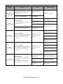
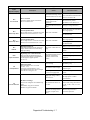
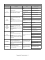
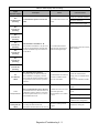
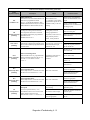
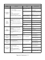
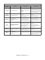
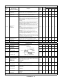
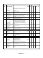
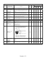
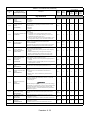
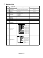
Option Board Models and Specifications
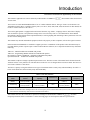
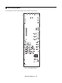
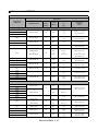
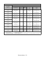
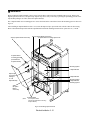
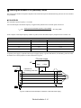
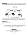
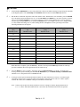
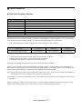
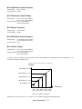
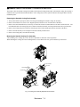
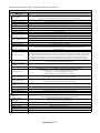
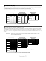
Up to three Option Boards can be mounted in the Drive. You can mount one board into each of the three option slots on the
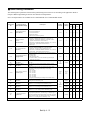
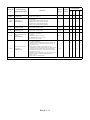
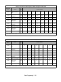
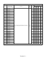
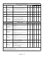
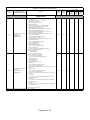
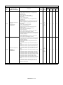
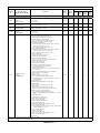
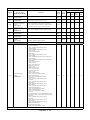
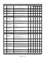
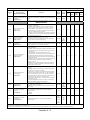
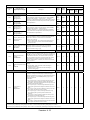
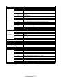
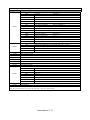
control board (A, C, and D) shown in Fig 2.16. The following Table 2.17 lists the type of Option Boards and their specifications.
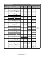
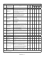
Table 2.17 Option Board Specifications
Option Board
PG Speed Control Boards
Model
Specifications
Mounting Location
PG-A2
Single open-collector feedback
A (4CN)
PG-B2
Single A/B open collector encoder feedback
A (4CN)
PG-D2
Single line-driver feedback
A (4CN)
PG-X2
Single A/B/Z line-driver encoder feedback
A (4CN)
PG-W2
Dual A/B/Z line-driver encoder feedback
A (4CN)
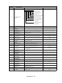
AI-14U
Analog input
0 to 10Vdc (20kΩ), 1 channel
4 to 20mA (250Ω), 1 channel
Input resolution: 14-bit
C (2CN)
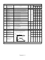
AI-14B
Analog input
0 to 10Vdc (20kΩ)
4 to 20mA (250Ω), 3 channels (V or I)
Input resolution: 13-bit plus sign bit
C (2CN)
AI-14B2
Isolated analog input
0 to 10Vdc (20kΩ)
4 to 20mA (250Ω), 3 channels (V or I)
Input resolution: 13-bit plus sign bit
C (2CN)
DI-08
8-bit digital input
C (2CN)
DI-16H2
16-bit digital input
C (2CN)
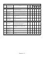
Speed Reference Boards
DeviceNet
Communications Board
SI-NX
DeviceNet communications
C (2CN)
Profibus-DP
Communications Board
SI-PX
Profibus-DP communications
C (2CN)
InterBus-S
Communications Board
SI-RX
InterBus-S communications
C (2CN)
CANopen
Communications Board
SI-SX
CANopen communications
C (2CN)
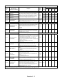
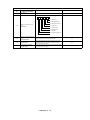
AO-08
Analog output, 8-bit 2 channels
D (3CN)
AO-12
Analog output, 11-bit plus sign bit, 2 channels
D (3CN)
Isolated analog output, 11-bit plus sign bit, 2 channels
D (3CN)
Six photocoupler outputs and 2 relay outputs
D (3CN)
DO-02C
2 relay outputs
D (3CN)
PO-36F
Pulse-train output
D (3CN)
Analog Monitor Boards
AO-12B
DO-08
Digital Output Boards
Electrical Installation 2 - 30