1
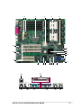
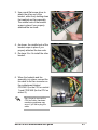
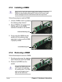
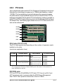
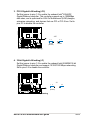
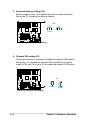
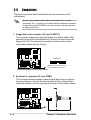
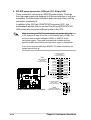
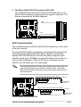
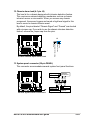
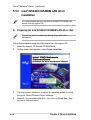
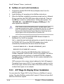
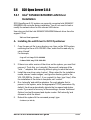
6. CPU, Chassis, and Power Fan Connectors
(3-pin CPU_FAN1, CPU_FAN2, CHASSIS_FAN1, CHASSIS_FAN2)
The fan connectors support cooling fans of 350mA~740mA (8.88W
max.) or a total of 1A~2.22A (26.64W max.) at +12V. Connect the fan
cables to the fan connectors on the motherboard, making sure that the
black wire of each cable matches the ground pin of the connector.
CPU_FAN1
Rotation
+12V
GND
®
PU-DLS
Do not forget to connect the fan cables to the fan connectors. Lack of
sufficient air flow within the system may damage the motherboard
components. These are not jumpers! DO NOT place jumper caps on
the fan connectors!
PU-DLS 12-V Fan Connectors
Rotation
+12V
GND
CHASSIS_FAN1
CHASSIS_FAN2
GND
+12V
Rotation
CPU_FAN2
GND
+12V
Rotation
7. Wake-On-Ring Connector (2-pin WOR1)
This connector connects to internal modem cards with a Wake-OnRing output. The connector powers up the system when a ringup
packet or signal is received through the internal modem card.
®
PU-DLS
For external modems, Wake-On-Ring is detected through the COM
port.
WOR1
Ring#
Ground
PU-DLS Wake-On-Ring Connector
2-22
Chapter 2: Hardware information