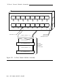
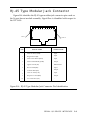
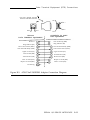
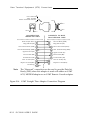
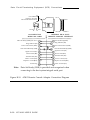
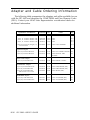
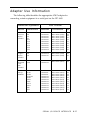
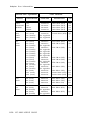
1
AT&T
305-920
Issue 1
AT&T Intelligent Ports Card
Model 1600 (IPC-1600)
User’s Guide
NOTICE
The information in this document is subject to change without notice.
AT&T assumes no responsibility for any errors that may appear in this document.
Copyright© 1989 AT&T
All Rights Reserved
Printed in U.S.A.
Table of Contents
Preface
Limited Warranty
P-1
RF Interference Warning
P-3
Trademarks
P-4
Ordering Information
P-5
Training Information
P-6
1.
Overview
Guide Organization
1-1
What Is an IPC-1600?
1-3
IPC-1600 Architecture
1-5
Ports and Drivers
1-6
Information in the Examples
1-7
Hexadecimal Notation
1-8
MS-DOS and UNIX System IPC-1600 Use Strategy
1-9
TABLE OF CONTENTS
i
Table of Contents
2.
MS-DOS Device Driver Installation
Introduction
2-1
Installation Procedure
2-2
Accessing Serial Ports
2-15
Removing the MS-DOS Device Driver
2-16
Limitations of the IPC-1600 MS-DOS Device Driver
2-18
3.
UNIX System Device Driver Installation
Introduction
3-1
Tunable Parameters and Memory Guidelines
3-2
General Installation Procedures
3-4
Installation Procedures
3-5
Modifying Kernel Configuration
4..
3-19
Hardware Installation
Introduction
4-1
Preparation
4-2
Connect the 16-Ports Fanout Module Cables
4-4
Connect the Ribbon Cables to the IPC-1600
4-5
Install the Board
4-6
ii
IPC-1600 USER’S GUIDE
Table of Contents
5.
Managing the Serial Ports
Introduction
5-1
Definition of IPC-1600 Device Node Names
5-2
IPC-1600 Administration Via hipcutils
5-6
UNIX System V Release 3.2 Administration Via FACE
5-7
6.
System Features
Features
6-1
Performance Characteristics
6-3
Power Consumption
6-5
7.
Troubleshooting the Intelligent Ports Card
Introduction
7-1
MS-DOS Boot Error Message
7-2
IPC-1600 Diagnostics
7-3
Helpful Hints
7-10
TABLE OF CONTENTS
iii
Table of Contents
Appendices
A.
Hardware Parameter Settings
Switch, Jumper, Connector Location Information
A-1
DS1 Switch Settings—Controller Memory Starting
Address
A-3
DS1 Switch Settings—I/O Port Address
A-8
DS2 Switch Settings—Interrupt Request Level
A-10
Local Program Memory Size Select Jumper J1
A-12
Sample Configuration Record
A-13
B.
Serial Input/Output Device Interface
Serial Port Characteristics
B-1
Voltage Envelope
B-2
IPC-1600 80-Pin Headers P3 and P4
B-3
16-Ports Fanout Module Assembly
B-7
RJ-45 Type Modular Jack Connector
B-9
Data Terminal Equipment (DTE) Connections
B-10
Data Circuit-Terminating Equipment (DCE)
Connections
B-16
10-Conductor Modular Cables
B-19
iv
IPC-1600 USER’S GUIDE
Table of Contents
AT&T 10-Pin Extender Adapter
B-21
Compatibility with Other I/O System Cabling
B-22
Adapter and Cable Ordering Information
B-26
Adapter Use Information
B-27
C.
AT&T IPC-1600 Ports Cabinet
General Description
C-1
Installation Information
C-2
Glossary
GL-1
Index
IN-1
TABLE OF CONTENTS
V
IPC-1600 USER’S GUIDE
List of Figures
Figure A-1:
Figure A-2:
Figure A-3:
Figure
Figure
Figure
Figure
A-4:
A-5:
B-1:
B-2:
Figure B-3:
Figure B-4:
Figure B-5:
Figure B-6:
Figure B-7:
Figure B-8:
Figure B-9:
Figure B-10:
Figure B-11:
Figure B-12:
Figure B-13:
Figure B-14:
Figure C-1:
Figure C-2:
Switch, Jumper, and Connector Location
Information
DS1 Controller Memory Starting Address Switches
(Default Setting)
DS1 Input/Output Port Address Switches (Default
Setting)
DS2 Interrupt Request Level (Default Setting)
Sample Configuration Record
RS-232C Voltage Envelope
80-Pin Headers P3 and P4 Connector Pin
Identification
16-Ports Fanout Module Assembly
RJ-45 Type Modular Jack Connector Pin
Identification
AT&T Null MODEM Adapter Connection
Diagram
AT&T Straight Thru Adapter Connection Diagram
AT&T Terminal/Printer Adapter Connection
Diagram
AT&T Printer (DTR) Adapter Connection Diagram
AT&T ACU/MODEM (DCE) Adapter Connection
Diagram
AT&T Remote Console Adapter Connection
Diagram
10-Conductor Modular Cable Connector Pin
Identification
AT&T 10-Pin Extender Adapter Connection
Diagram
IPC-1600 Connection to Existing IPC-802 Cabling
IPC-1600 Connection to Existing 3B2 Computer
PORTS/EPORTS Cabling
AT&T IPC-1600 Ports Cabinet
AT&T IPC-1600 Ports Cabinet Assembly Drawing
A-2
A-3
A-8
A-10
A-14
B-2
B-4
B-8
B-9
B-11
B-12
B-14
B-15
B-17
B-18
B-20
B-21
B-23
B-25
C-5
C-6
LIST OF FIGURES Vii
Preface
Limited Warranty
AT&T warrants that this product will be free of defects in materials and
workmanship on the date of purchase and that AT&T, at its sole option, will
repair or replace this product, provided that you report such a defect to AT&T
or an AT&T authorized dealer within one (1) year from the date of purchase.
If AT&T concludes that the product cannot readily be repaired or replaced,
AT&T may accept return of this product and refund your purchase price.
Repair parts and replacement products will be furnished on an exchange basis
and will be new, remanufactured, or refurbished, at the discretion of AT&T.
All replaced parts and products become the property of AT&T. This limited
warranty does not include repair of damages to the product resulting from
accident, disaster, misuse, abuse, non-AT&T modification of the product, or
other events outside AT&T’s reasonable control or circumstances not arising
under normal operating conditions.
Limited Warranty Service, during the specified warranty period, may be
obtained by returning the failed part or the product to an authorized AT&T
dealer, or by sending it via mail or carrier to AT&T in accordance with the
instructions provided to you by the AT&T Customer Service and providing
proof of purchase date. If this product is returned to AT&T, you agree to
insure the product or assume risk of loss or damages in transit, to prepay
shipping charges to the designated warranty service location and to ship the
product in the original shipping container or the equivalent. Contact your
authorized AT&T dealer or, if purchased directly from AT&T, your AT&T
Account Executive for further information.
PREFACE
P-1
Limited Warranty
All express or implied warranties for this product, including the warranties
or merchantability and fitness for a particular purpose, are limited in effect
and duration as stated above from the date of purchase, and no warranties,
whether express or implied, will apply after this period. Some states do not
allow limitations on how long an implied warranty lasts, so the above
limitations may not apply to you.
If this product is not free of defects in material and workmanship as
warranted above, your sole remedy shall be repair, replacement, or refund as
provided above. In no event will AT&T, its dealers, or its suppliers be liable
to you for any damages, including any lost profits, lost savings, or other
incidental or consequential damages arising out of the use of or inability to
use such a product, even if AT&T or an authorized AT&T dealer or supplier
has been advised of the possibility of such damages, or for any claims by any
other party. Some states do not allow the exclusion or limitation of incidental
or consequential damages, so the above limitation or exclusion may not apply
to you.
This warranty gives you specific legal rights, and you may also have other
rights which may vary from state to state.
P-2
IPC-1600 USER’S GUIDE
RF Interference Warning
This equipment has been certified to comply with the limits for an FCC
Class B computing device, pursuant to Subpart J of Part 15 of FCC Rules.
All cables used to connect with peripherals must be shielded and
grounded for FCC Class B compliance. Operation with cables connected to
peripherals which are not shielded and grounded may result in interference to
radio and TV reception.
PREFACE
P-3
Trademarks
The following trademarks are used in this guide:
P-4
■
Hayes — Registered trademark of Hayes Microcomputer Products,
Incorporated
■
HP — Registered trademark of Hewlett-Packard Company
■
MS-DOS — Registered trademark of Microsoft Corporation
■
UNIX — Registered trademark of AT&T.
IPC-1600 USER’S GUIDE
Ordering Information
Additional copies of this document can be ordered by calling:
Toll free:
Toll:
1-800-432-6600
In the U.S.A.
1-800-255-1242
In Canada
1-317-352-8557
Worldwide
OR by writing to:
AT&T Customer Information Center
Attn: Customer Service Representative
P.O. Box 19901
Indianapolis, IN 46219
PREFACE
P-5
Training Information
The AT&T Education and Training Catalogue of Courses and course
schedules are free and can be ordered by contacting your account executive or
by calling toll free:
1-800-554-6400 (extension 7150)
Training information can also be accessed electronically through our
computerized catalogue:
DIAL: 1-800-662-0662 or 1-614-764-5566
LOGIN: comcats
PASSWORD: 88cat
P-6
IPC-1600 USER’S GUIDE
Chapter 1: Overview
Guide Organization
This guide provides directions on how to install and set up the AT&T
Intelligent Ports Card, Model 1600 (IPC-1600). It also explains how the
product interacts with other components of your computer system and advises
you on troubleshooting.
The remainder of this guide is divided into the following:
*
■
Chapter 2, “MS-DOS* Device Driver Installation,” describes how to
install the MS-DOS device driver software.
■
Chapter 3, “UNIX System Device Driver Installation,” describes how
to install the UNIX system device driver software.
■
Chapter 4, “Hardware Installation,” provides general information about
installing the IPC-1600 board. Refer to the documentation that came
with your system for information about installing and removing
expansion bus slot boards.
■
Chapter 5, “Managing the Serial Ports,” defines the IPC-1600 device
node names and describes how to administer (manage) the serial ports
using either the hipcutils(1) command or the optional AT&T Framed
Access Command Environment (FACE) subsystem under the UNIX
system.
■
Chapter 6, “System Features,” reviews the IPC-1600 system features.
■
Chapter 7, “Troubleshooting the Intelligent Ports Card,” describes how
to run diagnostic tests supplied on the “Intelligent Ports (IPC-1600)
MS-DOS Device Drivers and Diagnostics, Version 1.0” diskette.
Information on how to use the Intelligent Ports Card with other
products and other “Helpful Hints” are also provided in this chapter.
®
Registered trademark of Microsoft Corporation
OVERVIEW 1-1
Guide Organization
1-2
■
Appendix A, “Hardware Parameter Settings,” provides information
about setting the Input/Output (I/O) port address, controller memory
starting address, and the Interrupt ReQuest (IRQ) level for the
IPC-1600. A sample configuration record is provided for keeping track
of installed card parameters and characteristics.
■
Appendix B, “Serial Input/Output Device Interface,” provides
information about port electrical and physical characteristics. Physical
characteristics include descriptions of the modular jacks and plugs used
to interface Data Terminal Equipment (DTE) and Data Circuitterminating Equipment (DCE). Compatibility with existing cabling
systems is also addressed.
■
Appendix C, “AT&T IPC-1600 Ports Cabinet,” provides information
about an optional cabinet for mounting two 16-Ports Fanout modules.
The cabinet provides wiring guides to facilitate the organized routing of
the cables and cable strain relief.
■
The Glossary identifies terms used in this guide.
■
The Index provides access to the information provided in this guide on
a subject basis.
IPC-1600 USER’S GUIDE
What Is an IPC-1600?
The AT&T Intelligent Ports Card, Model 1600 (IPC-1600) is a sixteen port,
intelligent, serial Input/Output (I/O) controller with an 80C186 16-bit
microprocessor running at 12.5 MHz. The sixteen RS-232, asynchronous ports
are wired to RJ-45 (10-pin) fanout modules via two 80-conductor ribbon
cables.
The IPC-1600 operates with the AT&T UNIX System V/386 Release 3.2
and later releases on the following machines:
■
AT&T 6386E Work Group System
■
AT&T 6386/25 Work Group System
■
AT&T 6386E/33 Work Group System
■
AT&T 6386E/33 Work Group System Model S.
The IPC-1600 growth kit (COMCODE 405980145) provides the following:
■
One AT&T IPC-1600 board (COMCODE 405977729).
■
Mounting hardware consisting of a mounting bracket and two
2.25-inch, long-shank screws (COMCODE 406112680).
■
One AT&T Intelligent Ports Card, Model 1600 (IPC-1600) User’s Guide,
Select Code 305-920 (COMCODE 105747182).
■
One AT&T IPC-1600 to 16-ports fanout cable assembly
(COMCODE 405980178) which provides two 7-foot (2 meters) long,
80-conductor cables for connecting an IPC-1600 board to a 16-Ports
Fanout module.
■
One 16-Ports Fanout module providing sixteen 10-pin RJ-45 type
modular connectors (COMCODE 405977869).
Note:
Separately orderable modular cables and adapters are
necessary to connect I/O devices to the serial ports.
See Appendix B, “Serial Input/Output Device
Interface” for modular cable and adapter information.
OVERVIEW
1-3
What Is an IPC-1600?
■
Two diskettes [one 3.5-inch, 720-KB diskette (COMCODE 405977737)
and one 5.25-inch, 360-KB diskette (COMCODE 405977752)] each
labeled “Intelligent Ports Card (IPC-1600) MS-DOS Device Drivers and
Diagnostics, Version 1.0.”
■
Two diskettes [one 3.5-inch, 1.44-MB diskette (COMCODE 405977786)
and one 5.25-inch, 1.2-MB diskette (COMCODE 405977802)] each
labeled “Intelligent Ports Card (IPC-1600) UNIX System V/386 Device
Drivers, Version 1.0.”
■
Standard insert material:
❑
Service Information Card
❑
Product Registration Card
❑
Warranty Card
❑
Read-Notice Card—Multilingual Card
❑
Software Limited Warranty Card.
A separately orderable AT&T IPC-1600 Ports Cabinet
(COMCODE 405977646) provides mounting space for two 16-Ports Fanout
modules. The AT&T IPC-1600 Ports Cabinet can be placed on the floor, a
table, or wall-mounted. Refer to Appendix C for additional information about
this optional cabinet.
1-4
IPC-1600 USER’S GUIDE
IPC-1600 Architecture
The architecture of the IPC-1600 provides many useful and powerful
multiuser capabilities under the UNIX system. Furthermore, single-user
applications using the IPC-1600 for general-purpose I/O, as well as for
industrial control, can be done under MS-DOS.
IPC-1600 features include the following:
■
One 80C186 16-bit microprocessor (12.5 MHz).
■
Industry Standard Architecture (ISA) bus connectors (any 16- or 32-bit
slot can be used).
■
One host Interrupt ReQuest (IRQ) level can be shared per 16 ports or
one IRQ level can be assigned for all IPC-1600s (maximum of 7 boards
[112 ports]).
■
A 64-KB dual-ported Static Random Access Memory (SRAM) is used for
data storage and buffering. This SRAM provides communications and
control between the host processor and the IPC-1600 microprocessor.
The host processor address range for this space is on 64KB boundaries
and is switch selectable. This SRAM is “zero-wait-state” to the
IPC-1600 microprocessor.
■
A 16KB RAM for local programs.
■
The use of a 16-bit data transfer on the Industry Standard Architecture
(ISA) bus for maximum efficiency.
Chapter 6, “System Features,” provides more detailed information.
OVERVIEW
1-5
Ports and Drivers
The software that takes care of the I/O tasks between the user
terminals/MODEMs/printers and the UNIX system is built into the IPC-1600
firmware to increase the UNIX system performance. End users get the benefit
of immediate keyboard/screen response and the enhancement of the overall
performance of the UNIX system. The UNIX system driver supports the 8-bit
character set.
The MS-DOS device driver supports an 8-bit character set and the
MS-DOS level interface.
1-6
IPC-1600 USER’S GUIDE
Information in the Examples
The contents of most of the displays presented in this guide depend on
the particular machine configuration. Therefore, the information displayed on
your terminal will vary from the information presented in the examples. In
particular, the installation software displays and display options are dynamic
with respect to available system configuration resources. All displays in this
guide were taken from an AT&T 6386E Work Group System (WGS).
The following notation scheme is used to show examples of terminal input
and output.
■
Text you enter on your terminal is shown in bold type.
■
Text displayed on your terminal by the computer is shown in
constant width type.
■
Comments and explanations in displays are shown in italic type to
separate them from the text representing computer input or output.
OVERVIEW
1-7
Hexadecimal Notation
Throughout this guide, base 16 numbers (hexadecimal) are denoted by a
lowercase letter “h” suffix. For example, 100h.
1-8
IPC-1600 USER’S GUIDE
MS-DOS and UNIX System IPC-1600 Use
Strategy
Native MS-DOS and UNIX System Operation
Requirement:
The host computer must be set up to have base
memory above 512KB (512KB to 640KB) disabled for
the IPC-1600 to use controller memory starting
addresses 080000h or 090000h. Refer to the
customer documentation that came with your
AT&T Work Group System (WGS) for information
on how to disable base memory.
If you plan to use both the native (boot) MS-DOS and the UNIX system
for the operation of the IPC-1600, proceed as follows.
1 . Follow Chapter 3, “UNIX System Device Driver Installation,”
procedures with the following recommendations.
❑
Install the IPC-1600 board(s) using controller memory address
space below 1MB.
❑
Configure multiple IPC-1600 boards to share one Interrupt
ReQuest (IRQ) level and share the same 64-KB controller
memory address space.
2 . After installing hardware (Chapter 4), install MS-DOS software
starting with Step 3 in Chapter 2. Be sure to specify same controller
memory starting address and I/O address(es) that were set when
installing the UNIX system device driver and IPC-1600 hardware.
OVERVIEW
1-9
MS-DOS and UNIX System IPC-1600 Use Strategy
MS-DOS Under Simul-Task and UNIX System
Operation
If you plan to use MS-DOS under Simul-Task 386 or to use only the
UNIX system for the operation of the IPC-1600, skip Chapter 2. Start with
Chapter 3, “UNIX System Device Driver Installation,” and follow the
instructions for the installation of the software. Then install the IPC-1600
board per Chapter 4, “Hardware Installation.”
Native MS-DOS Operation
If you plan to use only native MS-DOS for the operation of the
IPC-1600s, start with Chapter 2, “MS-DOS Device Driver Installation,” and
follow the instructions for the installation of the software and hardware. Skip
Chapter 3.
1-10
IPC-1600 USER’S GUIDE
Chapter 2: MS-DOS Device Driver Installation
Introduction
Comment:
If you are using only the UNIX system for Intelligent
Ports Card operation, you can skip this chapter and go
to Chapter 3, “UNIX System Device Driver
Installation.” If you plan to use MS-DOS under
Simul-Task 386, follow the procedures in Chapter 3.
The instructions in this chapter apply only to native
MS-DOS. See the section, “IPC-1600 Diagnostics,” in
Chapter 7 for diagnostics information.
This chapter provides instructions on how to install the MS-DOS device
driver and diagnostics, which are on the diskette labeled “Intelligent Ports
Card (IPC-1600) MS-DOS Device Drivers and Diagnostics, Version 1.0.”
Refer to Chapter 6, “System Features,” for information about the software
support offered through the MS-DOS device driver.
Note:
The same software is supplied on both a 5.25-inch diskette
and a 3.5-inch diskette.
The Intelligent Ports Card MS-DOS device driver supports the MS-DOS
level interfaces in such a way that virtually any software application can
access all serial I/O ports provided by the IPC-1600.
Requirement 1:
The IPC-1600 board(s) must be installed and the
I/O address, starting controller memory address,
and IRQ level initially set before executing the
IPC16CNF program.
Requirement 2:
Each board in the system must be assigned an
I/O address and the same starting controller
memory address. The hardware Interrupt
ReQuest (IRQ) level switches are all set to OFF
unless the UNIX system is also being used to
operate the board, in which case the UNIX
system switch setup takes precedence. If you
assign different controller memory addresses to
IPC-1600s, only one board at a time can be used
under native MS-DOS.
MS-DOS DEVICE DRIVER INSTALLATION
2-1
Installation Procedure
The following steps define the sequence of events for installing the
IPC-1600 for use in the native MS-DOS environment. Read the entire
procedure and supporting paragraphs before doing the installation. Write
down the hardware parameter settings for each board to be installed as you
read through the procedure the first time. Then refer to these notes when you
do the procedure.
Step 1:
Preconfigure the IPC-1600 boards by setting the DIP switches for
a unique I/O address, a starting controller memory address, and
IRQ level.
Step 2:
Install the hardware (IPC-1600 boards) using the instructions in
Chapter 4, “Hardware Installation.”
Step 3:
Power up the system and load the files on the “Intelligent Ports
Card (IPC-1600) MS-DOS Device Drivers and Diagnostics,
Version 1.0” diskette.
Step 4:
Create or edit the CONFIG.SYS file using an editor such as
EDLIN to include the DEVICE=\IPC\IPC16DOS.SYS
entry.
Step 5:
Execute the IPC16CNF program to configure the IPC-1600 and
configure the driver.
Step 6:
Reconfigure the IPC-1600 DIP switches if necessary to match the
software assignments.
Step 7:
Reboot the machine to install the driver.
The following paragraphs provide more information for each of the
installation steps. Note that Steps 5 through 7 can be executed when
necessary to reconfigure the driver and/or port characteristics.
2-2
IPC-1600 USER’S GUIDE
Installation Procedure
Preconfigure the IPC-1600 Boards
Set the starting controller memory address (DS1, SW8—1), the I/O
address (DS1, SW11—9), and the IRQ level (DS2, SW8—1) for each IPC-1600
to be installed. Note that IRQ levels are not used by the MS-DOS driver.
Therefore all DS2 switches should be set to the OFF position (Note 2). Refer
to Appendix A, “Hardware Parameter Settings,” for switch location and
decode information.
The following table identifies the initial options. The driver default
addresses are shown in bold type face.
Hardware Preconfiguration Options
Memory
Address
Input/Output
Address
Interrupt
Request
80000h
90000h
A0000h
B0000h
C0000h
D0000h
E0000h
100h
110h
120h
200h
220h
300h
320h
Set all
switches
to OFF
(Note 2)
Note 1:
The switches on the IPC-1600 board can be easily changed
with the board installed in the host system. All IPC-1600
boards must be set to the same memory address.
Note 2:
If the board is set up for the UNIX system, all IRQ switches
do not have to be set to the OFF position to use the
IPC-1600 in MS-DOS. The UNIX system IRQ switch
settings take precedence.
Note 3:
The IPC-1600 (16-bit transfer board) cannot share a 128-KB
memory address space with 8-bit transfer boards like a hard
disk controller board or a video display board.
MS-DOS DEVICE DRIVER INSTALLATION
2-3
Installation
Procedure
Install the Hardware
Refer to Chapter 4, “Hardware Installation,” and follow the instructions
for the installation of the board. Ignore any instructions in Chapter 4
involving the DS1 and DS2 DIP switches, since they have already been done
in this procedure.
Load the Software
Power up the system [AT&T Work Group System (WGC) computer] to
boot native MS-DOS (Version 3.0 or later) from either the floppy diskette or
the system disk drive.
Insert the MS-DOS device driver diskette into the appropriate diskette
drive and close the diskette drive door.
Use the MS-DOS COPY command to copy all files from the diskette to
the system disk. It is recommended that you create a separate directory for
the IPC-1600 files as shown in the following examples. Note that system
prompts are machine dependent.
As shown in the following screen display, first, shift from the “A” drive to
the “C” (system disk) drive and create a directory named IPC as follows.
A: $ C :
C : $ mkdir ipc
C: $
2-4
IPC-1600 USER’S GUIDE
Installation
Procedure
Now, change directory (cd) to IPC and copy the files on the diskette in the
“A” drive or in the “B” drive to the system disk drive as follows. The
example uses the “A” diskette drive; the system disk is the “C” drive.
Change directory to an optional separate directory to
contain the IPC-1600 software.
C: $ cd
ipc
Copy the files from the “A” drive to the “C” drive
C:\IPC $ copy
a:*.*
/v
A:IPC16CNF.EXE
A:IPC16DOS.SYS
A:IPC16DIA.COM
3 File(s) copied
C:\IPC
$
Remove the “Intelligent Ports Card (IPC-1600) MS-DOS Device Drivers
and Dagnostics, Version 1.0” diskette from the diskette drive and properly
store the diskette.
There are two files on the “Intelligent Ports Card (IPC-1600) MS-DOS
Device Drivers and Diagnostics, Version 1.0” diskette concerned with the
installation of the MS-DOS driver:
IPC16CNF.EXE
Use this command to configure the Intelligent Ports
Card driver characteristics.
IPC16DOS.SYS
MS-DOS device driver for the IPC-1600.
The IPC16DIA.COM file provided on the MS-DOS diskette is the IPC-1600
diagnostics. Diagnostics are described in Chapter 7.
MS-DOS DEVICE DRIVER INSTALLATION
2-5
Installation
Procedure
Create or Modify the CONFIG.SYS File
Use an editor, such as EDLIN, to change (or create) the CONFIG.SYS file
in the root directory of the drive from which you boot MS-DOS.
Add the following line to the CONFIG.SYS file if the IPC16DOS.SYS file is
in a separate directory. The complete path name must be specified for the
DEVICE entry. For example, if the driver is in the a directory path \IPC, the
CONFIG.SYS file entry is as follows.
DEVICE=\IPC\IPC16DOS.SYS
Add the following line to the CONFIG.SYS file if the IPC-1600 driver
(IPC16DOS.SYS file) is in the root directory.
DEVICE=IPC16DOS.SYS
2-6
IPC-1600 USER’S GUIDE
Installation
Procedure
Execute IPC16CNF to Configure the Driver
The IPC16CNF.EXE program is used to configure or reconfigured the
IPC-1600 MS-DOS driver and to specify individual channel (port) parameters.
The following screen shows the initial IPC16CNF program display.
IPC1600 CONFIGURATION PARAMETERS
#Brd
I/O
Memory
Driver
Start
Board
Port
Chnls
#
Window
Support
Chanl
------------------------------------------------------------------------0100
4
16
DOS
1
080000
20
16
0110
DOS
2
080000
0120
16
36
DOS
3
080000
16
0200
52
DOS
4
080000
0220
16
DOS
68
5
080000
0300
84
16
DOS
6
080000
16
0320
100
7
DOS
080000
|-----------------------------------------------------------------------|
N)umber of Brds
P)ort Address
M)emory Segment
C)hnl Params
D)river Support
Q)uit
S)tart Channel #
Select Configuration Option:
Each of the options shown on this initial screen display is described in the
following paragraphs.
MS-DOS DEVICE DRIVER INSTALLATION
2-7
Installation
Procedure
Number of Boards Option
The N)umber of Brds option is used to specify the number of installed
IPC-1600 boards. The default is seven boards. Once specified, the initial
table is redrawn to show the number selected.
Memory Segment Option
The M)emory Segment option is used to specify the controller memory
starting address for all IPC-1600 boards. When selected, the table is redrawn
to show the new data. Remember that if all IPC-1600s are to be usable under
native MS-DOS, all boards must have the same memory address. Select “8”
to specify the default address 080000h.
The following screen display shows the available memory address options.
Memory Window Segment
8) 80000h
9)90000h
A)
A0000h
B)B0000h
C)
C0000h
D) D0000h
E)E0000h
Select Configuration Option:
Driver Support Option
The D)river Support Option is used to specify DOS or INT 14 support.
The default is DOS support. INT 14 support is provided for experienced
users.
Selecting DOS support assigns and uses names for the individual
communications ports so that they can be accessed from DOS and high level
languages. The ports can also be accessed through INT 14h calls.
Selecting INT 14 support deactivates the DOS capability of assigning and
using names for the installed communications ports. This allows the channels
to be accessed only through INT 14h calls. If DOS support is not desired,
selecting this option decreases the size of the driver.
The following screen display shows how to select these options.
Driver Support
D)OS
Select Configuration Option:
2-8
IPC-1600 USER’S GUIDE
I)NT 14
Installation
Procedure
Start Channel Number Option
The S)tart Channel # option is used to specify the beginning channel
number for all IPC-1600 provided ports. Each IPC-1600 port in the system is
assigned a number that distinguishes it from the other ports in the system.
These channel numbers are used by the driver and INT 14h calls. Selecting
the starting channel number specifies the range of numbers the
communications ports will use. The standard MS-DOS COM1 and COM2
ports use channel numbers 0 and 1. The default starting channel number for
the first IPC-1600 port is 4.
The following screen display shows how to specify the starting channel
number.
Starting Channel Number for Board 1, Channel 0
Select Starting Channel # (0 - 255) :
Port Address Option
The P)ort Address option is used to specify the I/O address for the board
to the driver. The DS1, SW11—9 must be set to match the address specified
to the driver. The following screen display shows the available address.
Board I/O Port Options:
100
110
120
200
220
300
320
Select I/O Port Number:
MS-DOS DEVICE DRIVER INSTALLATION
2-9
Installation
Procedure
Channel Parameters Option
The following screen shows the initial display for changing parameters for
a given IPC-1600 board. The display shows the default parameters. After
selecting a channel, options are presented for changing the ENABLE, BAUD,
MODE, HANDSHAKE, and NAME parameters. The display is automatically
updated to show what channel has been selected and to show the parameter
data.
BOARD 1 PARAMETERS
ENABLE
BAUD
MODE
HANDSHAKE
NAME
CHANL
--------------------------------------------------DSBL
NONE
N,8,1
4
9600
COM5
DSBL
NONE
N,8,1
5
9600
COM6
6
DSBL
9600
N,8,1
NONE
COM7
DSBL
N,8,1
7
9600
NONE
COM8
N,8,1
DSBL
NONE
8
9600
COM9
9
DSBL
9600
N,8,1
NONE
COM10
N,8,1
NONE
10
DSBL
9600
COM11
N,8,1
11
DSBL
NONE
9600
COM12
12
DSBL
9600
N,8,1
NONE
COM13
N,8,1
DSBL
NONE
13
9600
COM14
N,8,1
14
DSBL
9600
NONE
COM15
N,8,1
15
DSBL
9600
NONE
COM16
16
DSBL
9600
N,8,1
NONE
COM17
N,8,1
17
DSBL
NONE
9600
COM18
N,8,1
18
DSBL
9600
NONE
COM19
19
DSBL
9600
N,8,1
NONE
COM20
Select Channel (#/Q) :
2-10
IPC-1600 USER’S GUIDE
Installation
Procedure
After selecting a channel, the following options are available.
Q)uit
E)nable
B)aud
Select Parameter:
M)ode
H)andshake
N)ame
C)hange
Chanl #
The E)nable option is used to enable (ENBL) or disable (DSBL) the
selected channel (port) as shown in the following screen display.
B) ENBL
A) DSBL
Select
Settings:
The B)aud option is used to set the BAUD rate for the selected channel
(port) as shown in the following screen display.
A)
50
G)
300
M) 3600
B)
75
H)
600
N) 4800
C)
110
I) 1200
O) 7200
D)134.5
J) 1800
P) 9600
E)
150
K) 2000
Q)19200
F)
200
L) 2400
R)38400
Select Baud Rate:
The M)ode option is used to set the parity, word size, and number of stop
bits, respectively. Parity can be none (N), odd (O), or even (E). The word
size can be 5, 6, 7, or 8 bits. The number of stop bits is 1 or 2. The following
screen display shows how these options are selected.
A)
G)
M)
S)
N,5,1
N,7,2
O,5,2
E,7,1
B)
H)
N)
T)
N,6,1
N,8,2
O,6,2
E,8,1
C)
I)
O)
U)
N,7,1
O,5,1
O,7,2
E,5,2
D)
J)
P)
V)
N,8,1
O,6,1
O,8,2
E,6,2
E)
K)
Q)
W)
N,5,2
O,7,1
E,5,1
E,7,2
F)
L)
R)
X)
N,6,2
O,8,1
E,6,1
E,8,2
Select Mode:
MS-DOS DEVICE DRIVER INSTALLATION
2-11
Installation
Procedure
The H)andshake option is used to select the flow control for the selected
channel (port). The following screen display shows how to select the flow
control options.
A) NONE
Select
Handshake
B) XON/XOFF
C) RTS/CTS
D) BOTH
Protocol:
The N)ame option is used to change the MS-DOS name assigned to the
channel. No name is used if INT 14 support has been selected. The
following screen display shows how to specify a new channel name.
Old Name : COM5
New Name (8 characters max.) :
The C)hange Chnl# option is used to select the target channel for the
other options in this group.
2-12
IPC-1600 USER’S GUIDE
Installation
Procedure
Finishing Up
Quitting the IPC16CNF program using the Q)uit option produces various
messages depending on what has been done before the exit request. During
the exit process, a combination of the following prompts can be displayed.
Re-Configure
the
IPC1600(s)
(Y/*)
:
Responding “Y” to this prompt causes the IPC-1600 to be
reprogrammed. The system can then be used without a reboot.
However, on the next reboot, the system will revert to the previous
configuration unless the changes are saved to the system disk.
Save
Changes
to
Disk
for
Re-Boot?
(Y/*)
:
Responding “Y” to this prompt changes the IPC16DOS.SYS file on the
system disk to reflect the new configuration data. The new
configuration is installed by rebooting the system. If the previous
prompt was to “Re-Configure the IPC1600(s)” and the response was
“Y”, the changes are currently in effect. However, on the next reboot,
the system will revert to the previous configuration unless the changes
are saved to the system disk.
Quit?
(Q/*)
:
Responding “Q” to this prompt terminates the program returns to
MS-DOS.
The following screen display shows the typical prompts after changing the
IPC-1600 configuration options and quitting for the initial installation.
Save Changes to Disk for
Quit? (Q/*) : Q
Re-boot to Load Driver
Re-Boot?
(Y/*)
: Y
MS-DOS DEVICE DRIVER INSTALLATION
2-13
Installation
Procedure
Reconfigure the Boards If Necessary
Requirement:
Be sure to take notes throughout this phase of
installation. Write down I/O addresses and the
memory addresses so that once the device drivers
have been installed you will have a permanent
record to which you may later refer. Likewise, if
you are going to remove or add a board, write
down any changes that you make in the process.
A sample configuration record is shown in
Appendix A.
Refer to Appendix A, “Hardware Parameter Settings,” for switch location
and decode information if it is necessary to change these settings to match the
software (driver) configuration established by the IPC16CNF program. Note
that Steps 5 through 7 (this discussion is Step 6) can be executed when
necessary to reconfigure the driver and/or port characteristics. The following
screen display shows the typical prompts associated with reconfiguration.
Re-Configure
the
IPC1600(s)
Save Changes to Disk for
Quit? (Q/*) : Q
Re-boot to Load Driver
(Y/*)
Re-Boot?
: Y
(Y/*)
: Y
Reboot the System
Reboot the system (AT&T WGS computer) to load the Intelligent Ports
Card MS-DOS device driver.
2-14
IPC-1600 USER’S GUIDE
Accessing Serial Ports
After you have completed the hardware phase of the installation and the
configured driver is loaded, use the serial I/O ports on the IPC-1600 as if they
were files with file names COM5 through COM20 ..., as applicable.
MS-DOS DEVICE DRIVER INSTALLATION
2-15
Removing the MS-DOS Device Driver
To remove the Intelligent Ports Card MS-DOS device driver from the
system, use an editor, such as EDLIN, to delete the entry in the CONFIG.SYS
file which corresponds to DEVICE=\IPC\IPC16DOC.SYS.
Then reboot
the system.
If you want to free the system disk space occupied by the IPC-1600
software, delete (DEL) the IPC16DOS.SYS, IPC16CNF.EXE, and IPC16DIA.COM
files along with the IPC directory (RMDIR). Note, you may want to keep the
IPC16DIA program if you expect to run diagnostics from the system disk.
The following screen display shows how to delete (DEL) all files under
the IPC directory and then remove the directory (RMDIR).
Removes all files under the IPC directory.
C:\ $ d e l i p c
Are you sure (Y/N)? y
C:\ $ r m d i r
ipc
C:\ $
After editing the CONFIG.SYS file,
reboot the system to reconfigure the system.
2-16
lPC-1600 USER’S GUIDE
Removing the MS-DOS Device Driver
The following screen display shows how to remove only IPC-1600 driver
and configuration software files from the system disk. The IPC16DIA
diagnostic program remains on the system disk.
C:\ $ d e l
ipc\ipc16dos.sys
C:\ $ d e l
ipc\ipc16conf.exe
C:\ $
After editing the CONFIG.SYS file,
reboot the system to reconfigure the system.
MS-DOS DEVICE DRIVER INSTALLATION
2-17
Limitations of the IPC-1600 MS-DOS
Device Driver
All IPC-1600 boards in the system must be assigned the same starting
controller memory address; otherwise, only one board can be accessed under
native MS-DOS. All IPC-1600s can be diagnosed regardless of controller
memory address assignments; however, the controller memory address switch
settings must be below 1MB.
This MS-DOS device driver will NOT drive the following:
■
Any indigenous serial I/O ports such as COM1: and COM2:.
■
The indigenous parallel printer ports LPT1: and LPT2:.
The built-in MS-DOS RS-232C and printer device drivers can coexist with
the Intelligent Ports Card MS-DOS device driver to provide services on the
indigenous ports.
Any application software that bypasses all MS-DOS device drivers and
controls the hardware directly will NOT work with an Intelligent Ports Card
and its MS-DOS device driver. However, those applications which bypass the
high-level MS-DOS interfaces and use INT 14 interfaces will work.
In the native MS-DOS environment, the recommended
machine-to-machine file transfer command is as follows:
COPY filename /B COMx / B
such that the entire file is transferred including the execution of the CTRL Z
keystroke sequence.
2-18
IPC-1600 USER’S GUIDE
Chapter 3: UNIX System Device Driver
Installation
Introduction
Comment:
If you are using only native MS-DOS for IPC-1600
operation, you can skip this chapter. Chapter 2,
“MS-DOS Device Driver Installation,” provides
MS-DOS driver installation and setup instructions. If
you intend to run MS-DOS under Simul-Task 386, use
the installation instruction in this chapter.
This chapter provides instructions for installing the IPC-1600 UNIX
system device driver, which is on the diskette labeled “Intelligent Ports Card
(IPC-1600) UNIX System V/386 Device Drivers, Version 1.0.” This chapter
also provides software-related information about removing a board and
installing additional boards.
Note:
The same software is provided on both a 5.25-inch diskette
and a 3.5-inch diskette.
It is strongly recommended that you install the device driver before you
install the hardware.
Requirement 1:
Certain system tunable parameters should be
adjusted to obtain proper system performance.
Also, sufficient system memory must be
available to support the number of boards being
installed. Refer to the “Tunable Parameters and
Memory Requirements” section of this chapter
for more information. It is recommended that
the tunable parameters be adjusted before
installing the IPC-1600 UNIX system software to
avoid having to do a separate idbuild process.
Requirement 2:
Be sure to take notes throughout this phase of
installation. Write down the Interrupt ReQuest
(IRQ) assignment(s), I/O address(es), and the
controller memory address(es) so that once the
device driver has been installed you will have a
permanent record to which you may refer when
you install the hardware. Likewise, if you are
going to remove or add a board, write down any
changes that you make in the process. A sample
configuration record is shown in Appendix A.
UNIX SYSTEM DEVICE DRIVER INSTALLATION
3-1
Tunable Parameters and Memory
Guidelines
The following table shows the tunable parameter guidelines for IPC-1600.
IPC-1600 TUNABLE PARAMETERS
SYSTEM MEMORY
PARAMETER
NCLIST
NPROC
NREGION
2MB
4MB
8MB
16 MB+
120
100
210
170
150
300
560
200
600
1180
400
1200
The installation of the IPC-1600 UNIX system driver and related software
is independent of these requirements. However, to obtain proper system
performance, these parameters should be adjusted before the installation of
the IPC-1600. Refer to the UNIX System V/ 386 Operations/System
Administration Guide for additional information and procedures on setting
tunable parameters. By adjusting these parameters and then installing the
IPC-1600 UNIX system software, only one system reboot is necessary to
install both the new tunable parameter data and the IPC-1600 data.
Failure to adjust these parameters may result in table overflow warning
messages and poor performance.
3-2
IPC-1600 USER’S GUIDE
Tunable Parameters and Memory Guidelines
Sufficient system memory must be available to support the number of
IPC-1600 boards being installed. The following system memory guidelines
should be followed.
IPC-1600 SYSTEM
MEMORY GUIDELINES
NUMBER
OF
IPC-1600s
MINIMUM
SYSTEM
MEMORY
1
2MB
2 OR 3
4MB
4
8MB
5 TO 7
16MB
UNIX SYSTEM DEVICE DRIVER INSTALLATION
3-3
General Installation Procedures
Power up the AT&T WGS computer, making sure that no diskette is in
the diskette drive(s) during the boot phase. Wait until the UNIX system is
ready, and then log in using either “root” or the privileged access user
administration login you have been assigned.
Insert the “Intelligent Ports Card (IPC-1600) UNIX System V/386 Device
Drivers, Version 1.0” diskette into the appropriate diskette drive (5.25-inch or
3.5-inch drive) and close the diskette drive door.
At the UNIX system prompt, enter the following:
installpkg
Press the ENTER key. This invokes the UNIX system software package
installation program, which allows you to install the IPC-1600 UNIX system
serial I/O driver.
More information about using the installpkg command is given in the
UNIX System V/386 Operations/System Administration Guide.
Note 1:
Each IPC-1600 board in the system must be assigned a
unique I/O address, a controller memory address range, and
a hardware Interrupt ReQuest (IRQ) level which do not
conflict with any other board types in the system. All
IPC-1600 boards in a system must be set up to support ONE
of the following conditions:
1.
Share controller memory and share one IRQ level
(preferred condition)
2.
Share controller memory and have unique IRQ
levels
3.
Unique controller memory address assignments and
share one IRQ level
4. Unique controller memory address assignments and
unique IRQ levels.
Note 2:
3-4
The use of 080000h or 090000h as the controller memory
starting address requires that the base memory above 512KB
(512KB to 640KB) be disabled.
IPC-1600 USER’S GUIDE
Installation Procedures
Comment 1:
The installation software displays are dynamic and
depend on the type and configuration of the
machine. All possibilities are not presented in the
examples.
Comment 2:
AT&T Framed Access Command Environment
(FACE) subsystem is an optionally orderable
product. If available, the AT&T FACE software
should be installed before installing the IPC-1600
software.
Specify the Type of Installation
At the start of the installation process, you may be asked to specify what
is to be installed. The following screen shows the installation options with
AT&T FACE subsystem already installed.
Please select the type of installation from the list below:
1. Install device driver only.
2. Install device driver and FACE administration menus.
3. Quit
Type:
UNIX SYSTEM DEVICE DRIVER INSTALLATION
3-5
Installation Procedures
Enter the number corresponding to the action you want to specify. After
you specify either item 1 or 2, you will be asked to confirm your choice.
Specifying item 3 terminates the installation process with nothing being
installed.
Select option 2 to install the device driver and the AT&T FACE menus for
the IPC-1600.
The installation process searches the system data for available:
3-6
■
Interrupt ReQuest (IRQ) levels
■
Starting I/O addresses
■
Starting controller memory addresses.
IPC-1600 USER’S GUIDE
Installation
Procedures
Specify Shared or Board-Unique Hardware
Interrupt Assignment
The installation process then asks you to specify how hardware interrupts
are to be assigned.
The IPC-1600, Intelligent Ports Card - Version 1.0
package allows the ports boards to be configured to all use the same
interrupt (shared) or for each board to be configured to a different
interrupt. If interrupts are shared, a maximum of 7 ports boards
may be installed. If each board is configured to a different interrupt,
then at most 5 can be installed.
Do you want to share interrupts among all boards? (y or n)
If you specify to share an interrupt level among all boards, you are then
asked to select the interrupt to be used by all IPC-1600 boards as follows.
The device driver used for IPC-1600, Intelligent Ports Card
- Version 1.0 allows all the boards installed to be strapped
to the same interrupt. Please select the interrupt that
will be used from the list below. The available
interrupt(s) for the ports boards are:
IRQ
IRQ
IRQ
IRQ
IRQ
3
5
10 (default)
11
12
Type the interrupt number and strike the ENTER key or type
Q to cancel installation. Striking the ENTER alone will
select the default.
Enter Interrupt:
UNIX SYSTEM DEVICE DRIVER INSTALLATION
3-7
Installation
Procedures
Specify Shared or Board-Unique Controller
Memory Assignment
The installation process then asks you to specify how controller memory is
to be assigned.
The IPC-1600, Intelligent Ports Card - Version 1.0
package allows the ports boards to be configured to all use the same
controller memory (shared) or for each board to be configured to
a different controller memory starting address.
Do you want to share controller memory address among
all boards? (y or n)
3-8
IPC-1600 USER'S GUIDE
Installation
Procedures
If you specify to share controller memory among all boards, you are then
asked to select the controller memory starting address to be used by all
IPC-1600 boards as follows. The IPC-1600 comes from the factory with the
controller memory address range set to 080000h-08FFFFh. Remember to
select a controller memory address range which does not conflict with other
board types in the system.
The device driver used for IPC-1600, Intelligent Ports Card
- Version 1.0 allows all the boards installed be strapped
to the same controller memory address. Please select the
controller memory address that will be used from the list
below. The available controller memory address(es) for the
ports boards are:
Starting Memory address(s):
080000
180000
300000
480000
600000
780000
900000
A80000
C00000
D80000
F00000
(default)
090000
200000
380000
500000
680000
800000
980000
B00000
C80000
E00000
F80000
100000
280000
400000
580000
700000
880000
A00000
B80000
D00000
E80000
Type the starting controller memory address and strike the
ENTER key or type Q to cancel installation. Striking the ENTER alone
will select the default:
UNIX SYSTEM DEVICE DRIVER INSTALLATION
3-9
Installation
Procedures
Specify the Number of Boards
You are then asked to specify the number of boards to be installed as
follows. Remember that the number of boards indicated in the example is
dynamic with respect to the system type and available system configuration
resources.
The current system configuration will allow for up to 7
IPC-1600 controller boards to be installed. How many IPC-1600
controller boards will you be installing?
(1-7, Q to quit)
Enter the number of boards that you are installing; remember to note this
number so that when you install the hardware you will be able to refer to this
record. Press the ENTER key after typing the number of boards.
For each board, you will be asked to specify the following sequence of
information:
■
Hardware Interrupt ReQuest (IRQ) level
■
Starting I/O address
■
Starting controller memory address.
After you specify these three items of data, you will be asked to confirm
your choices for the board. If you specified to share an interrupt level among
all IPC-1600 boards, the IRQ question is omitted from the loop. If you
specified to share the controller memory address among all IPC-1600 boards,
the starting controller memory address question is omitted from the loop.
3-10
IPC-1600 USER’S GUIDE
Installation
Procedures
Assigning Board-Unique Hardware Interrupt
Request Level
If you specified board-unique hardware interrupt assignments, the system
now displays a list of available hardware interrupts and prompts you to enter
the interrupt number to be assigned to the first board that you wish to install.
At the factory the hardware is set to IRQ10; if IRQ10 is already assigned, the
first available interrupt in the displayed list appears as the default. The
hardware IRQ setting(s) will be set in Chapter 4 to match the IRQ
assignment(s) made in this chapter.
The following is an example of how the display and prompt may appear
on your screen:
Please enter the following system configuration information for IPC-1600
Board 1. The available interrupt(s) for the IPC-1600 Board 1 are:
IRQ
IRQ
IRQ
IRQ
IRQ
3
5
10 (default)
11
12
Type the interrupt number and strike the ENTER key or type
Q to cancel installation. Striking the ENTER alone will
select the default.
Enter Interrupt:
Either press the ENTER key (to enter the default) or type in the name of
the interrupt that you wish to assign and then press ENTER.
Again, write down the IRQ settings so that you may refer to your records
during the hardware installation.
UNIX SYSTEM DEVICE DRIVER INSTALLATION
3-11
Installation
Procedures
Assigning an I/O Address
The system now displays a list of available I/O addresses and prompts
you to enter the I/O address to be assigned to the board. The IPC-1600
comes from the factory with the I/O address set to 100h; if I/O address 100h
is already assigned, the first available I/O address in the displayed list appears
as the default. The hardware I/O address will be set to match the software
assignment(s) later in Chapter 4. The following is an example of how the
display and prompt may appear on your screen:
Please enter the following system configuration information
for IPC-1600 Board 1. The available starting I/O addresses
for the IPC-1600 Board 1 are:
Starting
Starting
Starting
Starting
Starting
Starting
Starting
I/O
I/O
I/O
I/O
I/O
I/O
I/O
address:
address:
address:
address:
address:
address:
address:
100 (default)
110
120
200
220
300
320
Type the starting I/O address and strike the ENTER key or type Q
to cancel installation. Striking the ENTER alone will select the
default:
Remember that if you are adding more than one board, the I/O address
range should not conflict with any other boards in the system. Each board in
the system must be assigned a unique I/O address.
Either press the ENTER key (to enter the default) or type in the name of
the starting I/O address that you wish to assign and then press ENTER.
Be sure to write down the address(es) that you specify.
3-12
IPC-1600 USER’S GUIDE
Installation
Procedures
Assigning Board-Unique Starting Controller
Memory Address
If you specified board-unique controller memory assignment, the system
now displays a list of available starting controller memory addresses and
prompts you to enter the address to be assigned to the board. The IPC-1600
comes from the factory with the controller memory address range set to
080000h—08FFFFh; if 080000h—08FFFFh is already assigned, the first
available starting controller memory address in the displayed list appears as
the default. The hardware controller memory address range(s) will be set to
match the software assignment(s) later in Chapter 4. The following screen
shows the typical display.
Please enter the following system configuration information
for IPC-1600 Board 1. The available starting controller
memory addresses for the IPC-1600 Board 1 are:
Starting Memory address(s):
080000
180000
300000
480000
600000
780000
900000
A80000
C00000
D80000
F00000
(default)
090000
200000
380000
500000
680000
800000
980000
B00000
C80000
E00000
F80000
100000
280000
400000
580000
700000
880000
A00000
B80000
D00000
E80000
Type the starting controller memory address and strike the
ENTER key or type Q to cancel installation. Striking the ENTER alone
will select the default:
Either press the ENTER key (to enter the default) or type in the name of
the controller memory address that you wish to assign and then press
ENTER.
UNIX SYSTEM DEVICE DRIVER INSTALLATION
3-13
Installation Procedures
Remember that if you are adding more than one board, the controller
memory addresses should not conflict. The IPC-1600 is 16-bit transfer board
requiring 64KB of host memory. Also, 8-bit and 16-bit transfer boards cannot
share a 128KB memory window. Controller memory address space cannot
conflict with Basic Input/Output System (BIOS) shared memory.
Be sure to write down the address(es) that you specify.
3-14
lPC-1600 USER’S GUIDE
Installation Procedures
Confirming the Data
After you enter the three items of data, a confirmation screen displays
your choices and prompts you either to verify what you have selected or to
indicate that it is unacceptable. The following is an example of how the
display and prompt may appear on your screen:
***************************************************
Board
1
configuration :
Ports Card Type =
Interrupt Number =
I/O ports Starting
Controller Memory
IPC-1600
10
address = 100
Starting address = 080000
**************************************************
Is
this
configuration
acceptable?
(y
or
n)
To accept the data, press the Y key and then press the ENTER key. You
may now install another board or quit the installation sequence. However, if
you wish to change the data, press the N key and then press the ENTER key.
If you reject the configuration, you must go through the sequence of prompts
for this board from the beginning.
If you initially specified that you wanted to install more than one board,
you will be prompted to go through the same procedure for the remaining
boards. As noted earlier, if the factory-assigned default is already assigned,
the first available item in the displayed list automatically becomes the default.
The system limits the number of Ports boards that you can install
according to the availability of interrupts and addresses. A maximum of seven
boards can be supported (dependent on the machine configuration) if one IRQ
level is being shared among all the IPC-1600 boards.
To quit the installation sequence when quit is an option, press the Q key
and then press the ENTER key.
UNIX SYSTEM DEVICE DRIVER INSTALLATION
3-15
Installation Procedures
Following the acceptance of the last board, an overall IPC-1600 configuration
summary is displayed. The following is an example of how the display and
prompt may appear on your screen:
Board #
-------
Is
TYPE
----
IRQ
---
I/O Addr.
---------
Mem. Addr
---------
1.
IPC-1600
10
100
080000
2.
IPC-1600
10
110
080000
this
configuration
acceptable?
(y
or
n)
To accept the data, press the Y key and then press the ENTER key.
However, if you wish to change the data, press the N key and then press the
ENTER key. Rejecting the configuration terminates the installation script with
nothing being installed. To restart the installation process, enter installpkg at
the beginning of this chapter.
3-16
IPC-1600 USER’S GUIDE
Installation Procedures
Completing Driver Installation
After you enter Y in response to the last prompt, the system completes the
driver installation by rebuilding the UNIX system kernel. This process takes
several minutes.
The following message appears:
The UNIX Operating System will now be rebuilt.
This will take approximately 2 minutes. Please wait.
The UNIX Kernel has been rebuilt.
UNIX SYSTEM DEVICE DRIVER INSTALLATION
3-17
Installation Procedures
Once the kernel has been rebuilt, another message displays:
Confirm
To complete the install/remove process a shutdown is now
being initiated automatically.
Make sure your floppy drive is empty. If you are
installing or removing controller boards, you may power
down the system after the shutdown has completed.
Strike ENTER when ready
or ESC to stop.
Remove the “Intelligent Ports Card (IPC-1600) UNIX System V/386
Device Drivers, Version 1.0.” diskette from the diskette drive and properly
store the diskette.
Press ENTER. This automatically shuts down the system. You may now
proceed to the hardware phase of installation.
After you have completed the hardware phase of installation (Chapter 4),
you will need to power up the system, which will boot the UNIX system.
When the system reboots, a new kernel environment is set up and the
board(s) will be fully installed.
3-18
IPC-1600 USER’S GUIDE
Modifying Kernel Configuration
Removing All IPC-1600 Boards
To remove all IPC-1600 board information from the kernel, log in as
“root” and execute removepkg. When prompted, select the “IPC-1600,
Intelligent Ports Card — Version 1.0” item.
Changing IPC-1600 Configuration
You can reinstall the driver on top of the current driver when you need to
add or change the IPC-1600 configuration information. To change the existing
configuration of IPC-1600 board(s), reinstall the “Intelligent Ports Card
(IPC-1600) UNIX System V/386 Device Drivers, Version 1.0” software
package (installpkg). Specify the proper number of boards and then assign
the appropriate interrupt request level, I/O address, and starting memory
controller address for each board.
Following shutdown, power down the system and set the DIP switches on
the IPC-1600 to match the information specified to the device driver. The
new configuration will be installed when the system is powered up.
UNIX SYSTEM DEVICE DRIVER INSTALLATION
3-19
Chapter 4: Hardware Installation
Introduction
The IPC-1600 board can be installed in any 16-bit or 32-bit bus expansion
slot in following machines:
■
AT&T 6386E Work Group System
■
AT&T 6386/25 Work Group System
■
AT&T 6386E/33 Work Group System
■
AT&T 6386E/33 Work Group System Model S.
Refer to the appropriate “User's Guide” supplied with your machine for
board installation instructions. This chapter guides you through the process of
installing the appropriate hardware. However, refer to the documentation that
came with your system for instructions on how to install/remove a bus
expansion slot board.
Also, be sure to refer to the notes you were instructed to make when you
were installing the software (Chapters 2 and 3). You will need these notes to
set the various switch settings on the IPC-1600 board.
Although this chapter does not explicitly cover removing a board or
installing an additional board or boards at a later time, the instructions
provided here can help you do future hardware changes.
Note:
Each IPC-1600 board in the system must be assigned a unique
I/O address, a controller memory address range, and a
hardware Interrupt ReQuest (IRQ) level which do not conflict
with any other board types in the system. All IPC-1600
boards in a system must be set up to support ONE of the
following conditions:
1.
Share controller memory and share one IRQ level
(preferred condition)
2.
Share controller memory and have unique IRQ levels
3.
Unique controller memory address assignments and
share one IRQ level
4.
Unique controller memory address assignments and
unique IRQ levels.
HARDWARE INSTALLATION
4-1
Preparation
Prepare Machine for Installation
If the machine is powered-up and is running the UNIX operating system,
use the shutdown command to bring down the operating system as shown in
the following screen display.
# cd /
# shutdown
Set the power switch of the system and of all external devices to “OFF.”
Unplug the system module power cord.
Using the documentation that came with your machine, prepare an
expansion bus slot for the installation of a board. This will typically require
the removal of a cover and a board slot filler plate.
4-2
IPC-1600 USER’S GUIDE
Preparation
Prepare the IPC-1600 for Installation
Set the Controller Memory Starting Address
Locate the DS1 Dual In-line Package (DIP) switch (a group of eleven
switches) on the IPC-1600. Refer to Appendix A, “Hardware Parameter
Settings,“ for switch location information and instructions on how to set the
controller memory starting address (DS1, SW8 through SW1) to correspond to
the values established when installing the software (Chapters 2 and 3).
Set the Input/Output Port Address
Next, locate the DS1 DIP switch. Set the selected I/O port address (DS1,
SW11 through SW9). For switch location information and instructions on how
to set the selected I/O starting address, refer to Appendix A. Set the I/O port
address switches to correspond with the values specified when installing the
software (Chapter 2 and 3).
If you are adding more than one board, make sure that the selected I/O
starting addresses you are now specifying do not conflict.
Set the Interrupt Request Level
Locate the DS2 DIP switch. Follow the instructions in Appendix A for
setting the IRQ level. Again, each IPC-1600 board that you install can have
its own IRQ level or one IRQ can be used for all IPC-1600 boards. Set the
IRQ switches to correspond to the IRQ level specified when installing the
software (Chapters 2 and 3).
HARDWARE INSTALLATION
4-3
Connect the 16-Ports Fanout Module
Cables
After setting the I/O port address, the controller memory starting address,
and the hardware interrupt request level for the board, you are ready to
connect the ribbon cables and port modular cables to the 16-Ports Fanout
module as follows.
If you have the optional AT&T IPC-1600 Ports Cabinet, locate and install
the cabinet now. Refer to Appendix C, “AT&T IPC-1600 Ports Cabinet,” and
the documentation that came with the cabinet for installation information.
After installing the cabinet, return to this procedure to “Connect the Ribbon
Cables to the IPC-1600” and “Install the Board” in the host computer.
If you DO NOT have the optional AT&T IPC-1600 Ports Cabinet, locate
the two 80-conductor ribbon cables and the 16-Ports Fanout module. Connect
the ribbon cables to the 80-pin connectors at the rear of the 16-Ports Fanout
module. The connectors on the ribbon cables are keyed for proper alignment
with the connectors at the rear of the fanout module. Make sure that the
retaining clips are properly secured.
If you DO NOT have the optional AT&T IPC-1600 Ports Cabinet, connect
the port modular cables to the 16-Ports Fanout module. When connecting the
modular cables to the 16-Ports Fanout module, it is important to label
(identify) the circuit(s). The label information should include the port
identification (ttyxyy) and the connecting device identification. Be sure to
connect the ground lead of the modular cable to the ground lug on the
16-Ports Fanout module.
4-4
lPC-1600 USER’S GUIDE
Connect the Ribbon Cables to the
IPC-1600
Route the ribbon cables from the 16-Ports Fanout module to the host
computer. Thread the ends of the ribbon cables through the board slot
opening in the host computer and connect them to the IPC-1600 board. The
connectors are keyed for proper alignment with the 80-pin headers on the
board. Observe the port markings on the front of the 16-Ports Fanout module
to insure correct port numbering on the fanout module. Connect the ribbon
cable for ports 9 through 16 to header P3. Connect the ribbon cable for
ports 1 through 8 to header P4. Refer to Appendix B, “Serial Input/Output
Device Interface,” for more information on these connections. Make sure that
the retaining clips are properly secured.
HARDWARE INSTALLATION
4-5
Install the Board
Follow the instructions in the documentation that came with your machine
for installing a board.
Carefully pass the excess ribbon cable through the board slot opening
until the board can be plugged into the 16- or 32-bit Industry Standard
Architecture (ISA) bus connector. Align the IPC-1600 board with the selected
board slot and plug the board into the corresponding connector.
Secure the IPC-1600 board with the mounting bracket using the 2.25-inch
long-shank screws. Then secure the bracket to the chassis with the screw
previously used for the filler plate.
After the entire IPC-1600 system has been installed, check that all
mechanical connections have been tightened before putting the system back
together and applying power to the system. Make sure that all cables have
been neatly routed and do not pose a hazard to personnel.
4-6
IPC-1600 USER’S GUIDE
Chapter 5: Managing the Serial Ports
Introduction
This chapter defines the IPC-1600 device node names used in the UNIX
system. This chapter also describes how to manage the serial I/O ports using
either the hipcutils(1) command or the AT&T Framed Access Command
Environment (FACE), which is optionally available with the UNIX System
V/386 Release 3.2 and later. (If you are using the UNIX System V/386
Release 3.2 or later but do not have FACE, refer to the UNIX System V/386
Operations/System Administration Guide.)
MANAGING THE SERIAL PORTS
5-1
Definition of IPC-1600 Device Node
Names
Node Names
There are two classes of device node names:
■
ttyis xyy (for software)
■
ttyihxyy (for hardware).
The x is the board occurrence number. Board numbers are 1 through 7.
The yy is the port number on the IPC-1600 board. Port numbers are 01
through 16.
5-2
IPC-1600 USER’S GUIDE
Definition of IPC-1600 Device Node Names
The following table shows all available device names for the serial ports
with multiple IPC-1600 installation.
IPC-1600
Board
Number
Device Names for Ports 1 through 16
1
/dev/ttyis101 — /dev/ttyis116 (no RS-232C handshake)
/dev/ttyih101 — /dev/ttyih116 (with RS-232C handshake)
2
/dev/ttyis201 — /dev/ttyis216 (no RS-232C handshake)
/dev/ttyih201 — /dev/ttyih216 (with RS-232C handshake)
3
/dev/ttyis301 — /dev/ttyis316 (no RS-232C handshake)
/dev/ttyih301 — /dev/ttyih316 (with RS-232C handshake)
4
/dev/ttyis401 — /dev/ttyis416 (no RS-232C handshake)
/dev/ttyih401 — /dev/ttyih416 (with RS-232C handshake)
5
/dev/ttyis501 — /dev/ttyis516 (no RS-232C handshake)
/dev/ttyih501 — /dev/ttyih516 (with RS-232C handshake)
6
/dev/ttyis601 — /dev/ttyis616 (no RS-232C handshake)
/dev/ttyih601 — /dev/ttyih616 (with RS-232C handshake)
7
/dev/ttyis701 — /dev/ttyis716 (no RS-232C handshake)
/dev/ttyih701 — /dev/ttyih716 (with RS-232C handshake)
MANAGING THE SERIAL PORTS
5-3
Definition of IPC-1600 Device Node Names
Software Device Class
The /dev/ttyisxyy device type must be used for I/O devices (terminals,
printers, MODEMs, etc.) when software flow control is desired.
The ttyisxyy class of device node names does not support hardware flow
control via the standard Electronic Industries Association (EIA) RS-232C
hardware handshaking signals (CTS and RTS). Flow control is provided
under software control. Any change in the status of Data Carrier Detect
(DCD) causes the getty to respawn.
The /dev/ttyisxyy name directs the IPC-1600 to ignore all RS-232C
control signals, except Data Carrier Detect (DCD), and to use software flow
control over the Transmit Data (TD) and Receive Data (RD) lines. Characters
can be transmitted and received when DCD is not asserted. The connection is
dropped when DCD is asserted and then dropped.
5-4
IPC-1600 USER’S GUIDE
Definition of IPC-1600 Device Node Names
Hardware Device Class
The ttyihxyy provides the standard EIA RS-232C hardware handshaking
and monitors the following:
■
Data Carrier Detect (DCD)
■
Clear To Send (CTS)
■
Ring Indicator (RI).
The detection of the DCD loss causes the port to log off if the Hang UP
on final CLose (HUPCL) flag is set. In addition, the presence of the CTS
signal enables the IPC-1600 transmitter and the presence of the DCD signal
enables the IPC-1600 receiver.
The /dev/ttyih xyy device type directs the IPC-1600 to:
■
Turn ON the RS-232C control signals, such as Data Terminal Ready
(DTR) and Request To Send (RTS)
■
Monitor these input status signals:
— Clear To Send (CTS)
— Data Carrier Detect (DCD)
— Ring Indication (RI).
The /dev/ttyihxyy device type must be used with I/O devices (terminals,
printers, MODEMs, etc.) when RS-232C hardware handshake signals are
desired (RTS and CTS).
MANAGING THE SERIAL PORTS
5-5
IPC-1600 Administration Via hipcutils
The hipcutils command is used to administer IPC-1600 ports. The
command is used to reset ports that are hung or otherwise not operable and to
configure the Data Carrier Detect (DCD) wink and break durations for a port.
Refer to the hipcutils(1) manual page which is provided as part of this
package for additional information.
5-6
IPC-1600 USER'S GUIDE
UNIX System V Release 3.2
Administration Via FACE
The AT&T Framed Access Command Environment (FACE) subsystem is
an optionally orderable product which provides an enhanced UNIX system
user interface. Contact your AT&T Service Representative or authorized
dealer for more information.
The serial I/O ports are all under the control of the FACE subsystem
which is under the UNIX system.
AT&T FACE is a character-based user interface which presents the user
with a logical view of the UNIX System V environment. AT&T FACE displays
easy-to-use menus to commonly used commands, task scheduling, program
services, and administration. The AT&T FACE utility provides an
optionally-installable, context-sensitive help facility.
If your system includes FACE and the IPC-1600 FACE menus have been
installed, you can make the appropriate selections by invoking it. At the
UNIX system prompt (a # sign), enter face to invoke the AT&T FACE.
Once inside the AT&T FACE Menu, select the System Administration
option.
From the System Administration Menu, select the Peripherals Setup
option. From the Peripheral Setup Menu, select the following:
■
Serial Ports Setup option to administer the serial ports,
■
Configure IPC-1600 Port Break/Wink option to administer the duration
of the break and Data Carrier Detect (DCD) signals,
■
Reset IPC-1600 Port option to reset a port.
Follow the instructions provided in the UNIX System V/386 Release 3.2
FACE User’s/Administrator’s Guide.
When you have completed administration through FACE, press the F6
(CANCEL) key to return to the AT&T FACE Menu.
Note that when you are administering serial ports, the Flow Control field
is used to select the ttyis xyy or ttyihxyy device. Selecting the Software option
for the Flow Control field selects the ttyisxyy device; the Hardware option
selects the ttyihxyy device.
MANAGING THE SERIAL PORTS
5-7
UNIX System V Release 3.2 Administration Via FACE
In order for the Flow Control selection to select the device properly, you
must explicitly set the Flow Control field or, at the least, you must move the
cursor through the field.
For Serial Printer Setup using the IPC-1600, select the “Serial Printer Port
Setup” and refer to the UNIX System V/386 Release 3.2 FACE
User’s/Administrator’s Guide for additional information.
Refer to Chapter 7, “Troubleshooting the Intelligent Ports Card,” for some
“Helpful Hints” in setting port characteristics.
5-8
IPC-1600 USER’S GUIDE
Chapter 6: System Features
Features
The IPC-1600 works in either 16-bit or 32-bit expansion I/O slots.
The IPC-1600 provides sixteen identically configured serial I/O ports with
a full complement of Electronic Industries Association (EIA)
RS-232C/Consultative Committee International Telegraph and Telephone
(CCITT) V.28 standard interface on both input and output supporting the
following signals:
■
Transmit Data (TD)
■
Receive Data (RD)
■
Data Terminal Ready (DTR)
■
Data Set Ready (DSR)
■
Receive Line Signal Detector (RLSD) or
Data Carrier Detect (DCD)
■
Request To Send (RTS)
■
Clear To Send (CTS)
■
Ring Indicator (RI)
■
Signal Ground (SG).
Each serial port has the following capabilities:
■
Full or half-duplex mode.
■
Programmable data bits (5, 6, 7 or 8).
■
1 or 2 stop bits.
■
Error detection:
■
❑
Framing errors
❑
Parity errors
❑
Loss of carrier
❑
Break handling.
Parity options: EVEN/ODD/NONE parity.
SYSTEM FEATURES
6-1
Features
■
Break sequence (transmit data line held “low” for two consecutive
stop-bit sequences).
In addition, modem-handshaking line discipline and receive-error
detection (such as framing error, data overrun error, and parity error) are built
in.
Transmit and receive data are buffered through the on-board Static
Random Access Memory (SRAM) and passed between the IPC-1600 and the
host processor via the high-speed dual-ported SRAM to enhance system
performance.
The IPC-1600 comes with the following standard features:
■
On-board, high-speed SRAM
■
Error checking on receive
■
Input and output data hardware and software flow control.
The serial I/O ports can be mapped into the MS-DOS and UNIX system
environments to provide a total of 64 ports (four IPC-1600 boards). When
one IRQ level is shared among seven IPC-1600 boards, 112 ports can be
supported.
The IPC-1600 base memory address and I/O base address are both
configurable via on-board DIP switches.
One IRQ line can be assigned for each IPC-1600 or shared among all
equipped IPC-1600s out of a total possible eight interrupts (IRQ3—IRQ5,
IRQ7, IRQ10—IRQ12, and IRQ15). A maximum of seven boards can be
equipped when one IRQ is shared among all IPC-1600s. A maximum of four
board can be equipped when one IRQ is assigned per board.
Eight 8530 serial communications controllers function as dual-channel,
Universal Asynchronous Receiver-Transmitters (DUARTs) to provide a total of
sixteen RS-232C channels (ports) complete with the following features:
6-2
■
Programmable baud rates, data bits, parity bits, stop bits
■
Control of DTR, RTS, and TD
■
Detection of RD, CTS, DCD, RI, and BREAK.
IPC-1600 USER’S GUIDE
Performance Characteristics
The IPC-1600 supports the following bit per second rates: 38400, 19200,
9600, 4800, 2400, 1800, 1200, 600, 300, 200, 150, 134.5, 110, 75, and 50.
The performance of the IPC-1600 expressed in terms of line occupancy at
a prescribed baud rate in the raw and cooked modes with no flow control is as
follows. In the cooked mode, canonical processing is enabled. In the raw
mode, canonical processing is disabled. The line occupancy formula is:
Line Occupancy (%) =
Note:
# of transmitted characters per second
X 100
bit rate / bits per character
The line occupancy formula may have results greater than
100%. This is reserve capacity that is NOT achievable. The
following line occupancy results are typical of an
AT&T 6386E/33 WGS Model S with one IPC-1600 board.
The input capacity of the IPC-1600 is determined by the number of lines
(ports) simultaneously operating at 100% occupancy with no flow control as
follows.
Raw Mode:
16
16
8
2
ports at 4,800
ports at 9,600
ports at 19,200
ports at 38,400
bps
bps
bps
bps
Cooked Mode:
16
16
7
2
ports at 4,800
ports at 9,600
ports at 19,200
ports at 38,400
bps
bps
bps
bps (with 75% occupancy)
SYSTEM FEATURES
6-3
Performance Characteristics
The output capacity of the IPC-1600 is determined by the number of lines
(ports) simultaneously operating at 98% occupancy with no flow control as
follows.
Raw Mode:
16
16
14
7
ports at 4,800
ports at 9,600
ports at 19,200
ports at 38,400
bps
bps
bps
bps
Cooked Mode:
16
16
14
7
ports at 4,800
ports at 9,600
ports at 19,200
ports at 38,400
bps
bps
bps
bps
Operating beyond these input limits with no flow control will result in
loss of characters. Operating beyond these input limits WITH flow control
will result in decreased line occupancy and no data loss. No data loss is
associated with output regardless of flow control; however, reduced occupancy
will result if these limits are exceeded.
6-4
IPC-1600 USER’S GUIDE
Power Consumption
The IPC-1600 is supplied with +5V, +12V, and –12V via the Industry
Standard Architecture (ISA) adapter card. The total typical case power
consumption is as follows:
+5V @ 2.00 Amperes =
+12V @ 0.07 Amperes =
–12V @ 0.10 Amperes =
Total Power =
10.0 Watts
0.8 Watts
1.2 Watts
12.0 Watts (Typical)
SYSTEM FEATURES
6-5
Chapter 7: Troubleshooting the Intelligent
Ports Card
Introduction
This chapter includes detailed information on troubleshooting the
Intelligent Ports Card and the use of the diagnostic program supplied on the
“Intelligent Ports Card (IPC-1600) MS-DOS Device Drivers and Diagnostics,
Version 1.0” diskette. Information on how to use the IPC-1600 with other
products and other “Helpful Hints” are also provided in this chapter.
Note:
Systems running the UNIX operating system must either
create a native MS-DOS partition on the system disk and
make it the active partition or boot native MS-DOS from a
diskette drive to run the IPC-1600 diagnostics. The
IPC16DIA.COM file on the diskette is copied to the system
disk drive to run the diagnostics from the system disk drive.
When MS-DOS is booted from diskette, the IPC-1600
diagnostics are run from IPC-1600 MS-DOS diskette. Refer to
the MS-DOS documentation for information on creating a
MS-DOS partition and copying files.
TROUBLESHOOTING THE INTELLIGENT PORTS CARD
7-1
MS-DOS Boot Error Message
The following error messages may be displayed at system boot time and
can be caused by an incorrect board configuration.
SRAM MEMORY ERROR (Indicates faulty memory or memory not found.)
BIOS RESET ERROR
(Indicates BIOS failed to initialize correctly.)
The following error messages may be displayed at system boot time and
can be caused by a hardware problem.
FEPOS CODE MOVE ERROR
(Indicates error when loading the on-board operating system.)
FEPOS INITIALIZATION ERROR
(Indicates the on-board system failed to initialize.)
In response to these error messages, do the following.
7-2
■
Check that the board parameters match the parameters specified by the
IPC16CNF program.
■
Try to reload the IPC16DOS.SYS driver.
■
If the system still fails, recopy the driver from the “Intelligent Ports
Card (IPC-1600) MS-DOS Device Drivers and Diagnostics, Version 1.0”
diskette to the hard disk drive and try to reload the driver.
■
Run the diagnostics.
■
Call the AT&T HOTLINE at 1-800-922-0354 for help, as necessary.
IPC-1600 USER’S GUIDE
IPC-1600 Diagnostics
Copy Diagnostics to the System Disk
Comment:
This procedure is only for systems running native
MS-DOS from the system disk drive.
Power up the system [AT&T Work Group System (WGS) computer] to
boot native MS-DOS (Version 3.0 or later) from the system disk drive.
Insert the “Intelligent Ports Card (IPC-1600) MS-DOS Device Drivers and
Diagnostics, Version 1.0“ diskette into the appropriate diskette drive and close
the diskette drive door.
Use the MS-DOS COPY command to copy the IPC16DIA.COM file from
the diskette to the system disk. It is recommended that you create a separate
directory for the IPC-1600 files as shown in the following examples. Note
that system prompts are machine dependent.
As shown in the following screen display, first shift from the “A” drive to
the “C” (system disk) drive and create a directory named IPC as follows.
A: $ C:
C: $ m k d i r i p c
C: $
TROUBLESHOOTING THE INTELLIGENT PORTS CARD
7-3
IPC-1600
Diagnostics
Now, change directory (cd) to IPC and copy the IPC16DIA.COM file on
the diskette in the “A” drive or in the “B” drive to the system disk drive as
follows. The example uses the “A” drive.
Change directory to an optional separate directory to
contain the IPC-1600 software.
C: $ cd
ipc
Copy the file from the “A” drive to the “C” drive
C:\IPC $ c o p y a : i p c 1 6 d i a . c o m / v
A:IPC16DIA.COM
1 File(s) copied
C:\IPC
$
Remove the “Intelligent Ports Card (IPC-1600) MS-DOS Device Drivers
and Diagnostics, Version 1.0” diskette from the diskette drive and properly
store the diskette.
The IPC-1600 diagnostic program is now executable from the system disk
by entering \ipc\ipc16dia or just ipc16dia if the current working directory is
\IPC or if the command search path includes \IPC.
7-4
IPC-1600 USER’S GUIDE
IPC-1600
Diagnostics
How to Run Diagnostics
IPC-1600 diagnostics are run by executing the IPC16DIA program under
native MS-DOS. There are six diagnostics which can be selectively executed
from the IPC16DIA program. The program is terminated by the ESC key.
Note that it is necessary to change the controller memory address
assignment IPC-1600 boards set above 1MB to an address supported by
diagnostics. Remember to reset the controller memory address switches for
UNIX system operation, as applicable. Refer to Appendix A, “Hardware
Parameter Settings,” for switch location and value information. Diagnostics
support only controller memory starting addresses 080000h, 090000h,
0A00000, 0B00000h, 0C0000h, 0D0000h, and 0E0000h.
The opening screen of the IPC16DIA program is as follows. As you
respond to the prompts to enter the I/O address, starting memory controller
address, and IRQ for the board to be tested, the screen is automatically
updated to show the selections.
------------------------------------------------------------------------------***********
********
********
Version 1.5.0
IPC-1600 DIAGNOSTICS
------------------------------------------------------------------------------ESC will exit the IPC-1600 diagnostics and return to the system.
IPC-1600 Selected parameters:
I/O =
Memory =
IRQ =
Select an appropriate number (1-7) for the IPC-1600 I/O address:
7)320
2)110
5)220
6)300
4)200
1)100
3)120
TROUBLESHOOTING THE INTELLIGENT PORTS CARD
7-5
IPC-1600
Diagnostics
You are next asked to select the starting memory address for the board to
be tested as follows.
Select the appropriate number (1-7) for the IPC-1600 memory address:
1)80000H
2)90000H
3)A0000H
4)B0000H
5)C0000H
6)D0000H
7)E0000H
You are then asked to specify the IRQ level for the board to be tested as
follows.
Select the appropriate number (1-8) for the IPC-1600 IRQ:
1)3
2)4
3)5
4)7
5)10
6)11
7)12
8)15
After the I/O address, starting controller memory address, and IRQ level
are entered, any of the six tests can be repeated/executed by entering the test
number. A record is maintained on the screen of the number of times each
test is executed, the number of times each test passed, and the number of
times each test failed. The following screen shows the initial conditions after
the board to be tested has been defined.
-----------------------------------------------------------------------------********
***********
********
IPC-1600 DIAGNOSTICS
Version 1.5.0
------------------------------------------------------------------------------ESC will exit the IPC-1600 diagnostics and return to the system.
IPC-1600 Selected parameters:
I/O = 100
Memory = 80000H
IRQ = 10
Select the appropriate test number (1-6):
TOTAL
PASS
FAIL
1) Host 64K dual-ported memory tests
00
00
00
2) Host/IPC-1600 interface tests
00
00
00
3) IPC-1600 64K dual-ported memory tests
00
00
00
4) IPC-1600 16K local memory tests
00
00
00
5) IPC-1600 FEPOS integrity tests
00
00
00
6) IPC-1600 Communication ports tests
00
00
00
*******************************************************************************
7-6
lPC-1600 USER’S GUIDE
IPC-1600
Diagnostics
The IPC16DIA program is terminated by entering an escape (ESC). The
following screen shows that all diagnostics were successfully executed once for
the specified board and then an ESC entered to quit the program.
------------------------------------------------------------------------------********
********
***********
IPC-1600 DIAGNOSTICS
Version 1.5.0
------------------------------------------------------------------------------ESC will exit the IPC-1600 diagnostics and return to the system.
IPC-1600 Selected parameters:
I/O = 100
Memory = 80000H
IRQ = 10
FAIL
PASS
Select the appropriate test number (1-6) : <ESC> TOTAL
00
01
1) Host 64K dual-ported memory tests
01
01
00
01
2) Host/IPC-1600 interface tests
01
00
3) IPC-1600 64K dual-ported memory tests
01
00
01
4) IPC-1600 16K local memory tests
01
01
01
00
5) IPC-1600 FEPOS integrity tests
00
01
01
6) IPC-1600 Communication ports tests
*******************************************************************************
Test 1 in progress
Test passed
Select another test or ESC
IPC-1600 DIAGNOSTICS COMPLETE
TROUBLESHOOTING THE INTELLIGENT PORTS CARD
7-7
IPC-1600
Diagnostics
IPC-1600 Test Descriptions
Host 64KB Dual-Ported Memory Tests
The host processor dual-ported memory test diagnostics execute in the
host processor. These tests write to memory, read the memory, and compare
what is read to what was written. The IPC-1600 is held reset and the
dual-ported memory is enabled during test execution.
Host/lPC-1600 Interface Tests
The host processor/IPC-1600 interface tests execute in both the host
processor and the IPC-1600. The IPC-1600 is reset and the BIOS is
downloaded and executed. The host processor sends a Non-Maskable
Interrupt (NMI) to the IPC-1600 and the IPC-1600 responds with an IRQ to
acknowledge the NMI. The test passes if the interrupt communication is
successful in both directions.
IPC-1600 64K Dual-Ported Memory Tests
The dual-ported memory tests execute in both the host processor and the
IPC-1600. The IPC-1600 is reset and the BIOS is downloaded and executed.
The host processor downloads the diagnostic and transfers control from the
BIOS to the test routine. The diagnostic executive in the host processor
monitors the test results.
IPC-1600 16K Local Memory Tests
The 16KB local memory tests execute in both the host processor and the
IPC-1600. The IPC-1600 is reset and the BIOS is downloaded and executed.
The host processor then downloads the diagnostic tests and transfers control
from the BIOS to the test routine. The IPC-1600 executes the tests and the
diagnostic executive in the host processor monitors the test results.
IPC-1600 FEPOS Integrity Tests
The Front End Processor Operating System (FEPOS) integrity tests execute
in both the host processor and the IPC-1600. The IPC-1600 is reset, the BIOS
is downloaded and executed, and the FEPOS is downloaded and executed.
The diagnostic executive in the host processor monitors the FEP operating
system for test results.
7-8
IPC-1600 USER’S GUIDE
IPC-1600
Diagnostics
IPC-1600 Communication Ports Tests
The communication ports tests execute in both the host processor and the
IPC-1600. These tests use the IPC-1600 FEPOS to exercise each port on the
IPC-1600.
A combination of four baud rate (1200, 9600, 19200, and 38400 bps), four
data word sizes (5, 6, 7, and 8 bits), two stop bits (1 and 2), and three parity
selections (none, odd, and even) are used to test each port. Each port is
programmed to an internal loopback mode; therefore, external loop around
cables are not needed. However, note that the transmit data is available at the
port for external use while in the loopback mode. Any test data appearing on
a terminal connected to a port under test should be ignored since the
communication ports diagnostics are internal, standalone tests.
TROUBLESHOOTING THE INTELLIGENT PORTS CARD
7-9
Helpful Hints
Typically, the lower interrupts on the Industry Standard Architecture (ISA)
bus are used by other circuit boards in the system. Therefore, to prevent
configuration conflicts, try using some of the higher interrupts (IRQ 10,
IRQ 11, and IRQ 15) for the Intelligent Ports Card.
Make sure that the Intelligent Ports Card is installed in a 16-bit or a 32-bit
ISA-compatible bus slot.
Make sure that the hardware for the Intelligent Ports Card correctly
corresponds to the software selections for the I/O address, starting controller
memory address, interrupt request level, and board type.
When possible, use the default settings during the installation of the
Intelligent Ports Card.
Use shared IRQ level and controller memory starting address assignment
whenever possible.
Use controller memory address space below 1MB when possible. The use
of controller memory address space below 1MB is required for native MS-DOS
and diagnostics operation.
IPC-1600 boards may not work correctly if configured to share a 128KB
controller memory address space with other boards types. This is because the
IPC-1600 uses highly efficient 16-bit data transfers, and many other boards
use less efficient 8-bit technology. The ISA bus architecture precludes mixing
the two board types in the same 128KB address space.
Boards can be assigned controller memory address space above 1MB for
UNIX system operation and reassigned to use supported address space for the
purpose of diagnostics (by changing switch settings). Remember to reset the
switches for UNIX system operation.
Some applications may be coded assuming input buffer overflow at 256
characters. The IPC-1600 uses 257 character input buffers.
If you are using an 8-conductor cable, make sure that the cable is straight
through. A 3B2 computer 8-conductor cable that provides cross-overs
between the two modular ends will NOT work.
When using intelligent terminals (for example, AT&T 630 MTG) with
MS-DOS application programs through Simul-Task 386, make sure that all
function keys are correctly set.
7-10
IPC-1600 USER’S GUIDE
Helpful Hints
When using a Hayes* compatible MODEM, dial out once to configure the
MODEM before caIling into the MODEM.
The AT&T 446 Laser Printer and the HP† LaserJet Series II printer must
be installed on a serial port configured as a ttyihxyy device under the UNIX
system.
Use stty clocal to prevent loss of printer data for printers which raise Data
Carrier Detect (DCD) to signal erroneous data. These printers include the
AT&T 446 Laser Printer and the HP LaserJet Series II printer.
Use stty -clocal to allow UNIX system detection of printer disconnect.
* Registered trademark of Hayes Microcomputer Products, Incorporated
† Registered trademark of Hewlett-Packard Company
TROUBLESHOOTING THE INTELLIGENT PORTS CARD
7-11
Appendix A: Hardware Parameter Settings
Switch, Jumper, Connector Location
Information
The IPC-1600 has switches for selecting the following:
■
Controller memory starting address range (DS1, SW8 through SW1)
■
I/O port address (DS1, SW11 through SW9)
■
Hardware Interrupt ReQuest (IRQ) level (DS2, SW8 through SW1).
A jumper (shunt) is used for selecting the size of local program Random
Access Memory (RAM) (J1). Jumper J1 has been set at the factory to the
correct position. This jumper is documented in this appendix so you can
verify the selection.
Figure A-1 shows the location of DS1, DS2, J1, and the ports fanout
connections (P3 and P4) on the IPC-1600.
HARDWARE PARAMETER SETTINGS
A-1
Switch, Jumper, Connector Location Information
LOCAL PROGRAM
MEMORY SIZE
SELECT JUMPER (J1)
DS1
FANOUT CONNECTIONS
P3 (PORTS 9 — 16)
AND
P4 (PORTS 1 — 8)
DS2
J1
P3
DS2
DS1
11,
10,
9
8—1
CIRCUIT BOARD
8 — 1
INTERRUPT
REQUEST (IRQ)
LEVEL SWITCHES
CONTROLLER MEMORY
STARTING ADDRESS
SWITCHES
INPUT/OUTPUT
PORT ADDRESS
SWITCHES
Figure A-1: Switch, Jumper, and Connector Location Information
A-2
IPC-1600 USER’S GUIDE
P4
DS1 Switch Settings—Controller
Memory Starting Address
The factory set controller memory starting address (hexadecimal) is
80000h. (The h is used to denote a hexadecimal number.)
The Dual In-line Package (DIP) switch designated DS1, SW8 through SW1
selects the base or starting address of RAM. The address range must be set
such that it does not conflict with other RAM, ROM, or memory mapped I/O
address in the PC system. This address range must be consistent with the
software being used. Figure A-2 shows switch DS1 with the controller
memory starting address set to the factory setting (80000h).
CONTROLLER MEMORY
STARTING ADDRESS
SWITCHES (SW8 — SW1
SHOWN SET TO 80000h)
CIRCUIT BOARD
ON
11
10
9
8
7
6
5
4
3
2
1
OFF
- Switch pushed “IN” or to the
indicated position.
ON = 0 = Closed
OFF = 1 = Open
Figure A-2: DS1 Controller Memory Starting Address Switches (Default
Setting)
HARDWARE PARAMETER SETTINGS
A-3
DS1 Switch Settings—Controller Memory Starting Address
The following table shows the switch settings for some of the possible
controller memory starting addresses.
Note:
The IPC-1600 UNIX system driver installation scripts support
only selected starting controller memory addresses as
standard. The installation script displays the appropriate
standard addresses dependent on the available system
configuration resources. For the a typical AT&T 6386E Work
Group System, the installation script identifies the following
available controller memory addresses.
080000h
180000h
300000h
480000h
600000h
780000h
900000h
A80000h
C00000h
D80000h
F00000h
090000h
200000h
380000h
500000h
680000h
800000h
980000h
B00000h
C80000h
E00000h
F80000h
100000h
280000h
400000h
580000h
700000h
880000h
A00000h
B80000h
D00000h
E80000h
The recommended controller memory address range is
080000h through 0BFFFFh for the following machines:
■
AT&T 6386E Work Group System
■
AT&T 6386/25 Work Group System
■
AT&T 6386E/33 Work Group System
■
AT&T 6386E/33 Work Group System Model S.
The available controller memory address range is 080000h
through F80000h. However, the installation software supports
only selected starting addresses within this range as shown in the
previous listing.
A-4
IPC-1600 USER’S GUIDE
DS1 Switch Setings—Controller Memory Starting Address
DS1 CONTROLLER MEMORY STARTING ADDRESS SETTINGS
(See Figure A-2)
ADDRESS
SWITCH POSITIONS
(Hexadecimal)
8
(A23)
7
(A22)
6
(A21)
5
(A20)
4
(A19)
3
(A18)
2
(A17)
1
(A16)
080000—08FFFF*
090000—09FFFF
0A0000—0AFFFF
0B0000—0BFFFF
0C0000—0CFFFF
0D0000—0DFFFF
0E0000—0EFFFF
0F0000—0FFFFF
ON
ON
ON
ON
ON
ON
ON
ON
ON
ON
ON
ON
ON
ON
ON
ON
ON
ON
ON
ON
ON
ON
ON
ON
ON
ON
ON
ON
ON
ON
ON
ON
OFF
OFF
OFF
OFF
OFF
OFF
OFF
OFF
ON
ON
ON
ON
OFF
OFF
OFF
OFF
ON
ON
OFF
OFF
ON
ON
OFF
OFF
ON
OFF
ON
OFF
ON
OFF
ON
OFF
100000—10FFFF
110000—11FFFF
120000—12FFFF
130000—13FFFF
140000—14FFFF
150000—15FFFF
160000—16FFFF
170000—17FFFF
180000—18FFFF
190000—19FFFF
1A0000—1AFFFF
1B0000—1BFFFF
1C0000—1CFFFF
1D0000—1DFFFF
1E0000—1EFFFF
1F0000—1FFFFF
ON
ON
ON
ON
ON
ON
ON
ON
ON
ON
ON
ON
ON
ON
ON
ON
ON
ON
ON
ON
ON
ON
ON
ON
ON
ON
ON
ON
ON
ON
ON
ON
ON
ON
ON
ON
ON
ON
ON
ON
ON
ON
ON
ON
ON
ON
ON
ON
OFF
OFF
OFF
OFF
OFF
OFF
OFF
OFF
OFF
OFF
OFF
OFF
OFF
OFF
OFF
OFF
ON
ON
ON
ON
ON
ON
ON
ON
OFF
OFF
OFF
OFF
OFF
OFF
OFF
OFF
ON
ON
ON
ON
OFF
OFF
OFF
OFF
ON
ON
ON
ON
OFF
OFF
OFF
OFF
ON
ON
OFF
OFF
ON
ON
OFF
OFF
ON
ON
OFF
OFF
ON
ON
OFF
OFF
ON
OFF
ON
OFF
ON
OFF
ON
OFF
ON
OFF
ON
OFF
ON
OFF
ON
OFF
200000—20FFFF
210000—21FFFF
220000—22FFFF
230000—23FFFF
240000—24FFFF
250000—25FFFF
260000—26FFFF
270000—27FFFF
280000—28FFFF
290000—29FFFF
2A0000—2AFFFF
2B0000—2BFFFF
2C0000—2CFFFF
2D0000—2DFFFF
2E0000—2EFFFF
2F0000—2FFFFF
ON
ON
ON
ON
ON
ON
ON
ON
ON
ON
ON
ON
ON
ON
ON
ON
ON
ON
ON
ON
ON
ON
ON
ON
ON
ON
ON
ON
ON
ON
ON
ON
OFF
OFF
OFF
OFF
OFF
OFF
OFF
OFF
OFF
OFF
OFF
OFF
OFF
OFF
OFF
OFF
ON
ON
ON
ON
ON
ON
ON
ON
ON
ON
ON
ON
ON
ON
ON
ON
ON
ON
ON
ON
ON
ON
ON
ON
OFF
OFF
OFF
OFF
OFF
OFF
OFF
OFF
ON
ON
ON
ON
OFF
OFF
OFF
OFF
ON
ON
ON
ON
OFF
OFF
OFF
OFF
ON
ON
OFF
OFF
ON
ON
OFF
OFF
ON
ON
OFF
OFF
ON
ON
OFF
OFF
ON
OFF
ON
OFF
ON
OFF
ON
OFF
ON
OFF
ON
OFF
ON
OFF
ON
OFF
* Default (factory) controller memory starting address
HARDWARE PARAMETER SETTINGS
A-5
DS1 Switch Settings—Controller Memory Starting Address
DS1 CONTROLLER MEMORY STARTING ADDRESS SETTINGS (Cont’d)
(See Figure A-2)
ADDRESS
(Hexadecimal)
8
(A23)
3F0000—3FFFFF
ON
ON
6
(A21)
5
(A20)
4
(A19)
3
(A18)
2
(A17)
1
(A16)
OFF
OFF
ON
ON
ON
ON
I
I
I
I
I
I
I
I
C00000—C0FFFF
C10000—C1FFFF
C20000—C2FFFF
C30000—C3FFFF
C40000—C4FFFF
C50000—C5FFFF
C60000—C6FFFF
C70000—C7FFFF
C80000—C8FFFF
C90000—C9FFFF
CA0000—CAFFFF
CB0000—CBFFFF
CC0000—CCFFFF
CD0000—CDFFFF
CE0000—CEFFFF
CF0000—CFFFFF
OFF
OFF
OFF
OFF
OFF
OFF
OFF
OFF
OFF
OFF
OFF
OFF
OFF
OFF
OFF
OFF
OFF
OFF
OFF
OFF
OFF
OFF
OFF
OFF
OFF
OFF
OFF
OFF
OFF
OFF
OFF
OFF
ON
ON
ON
ON
ON
ON
ON
ON
ON
ON
ON
ON
ON
ON
ON
ON
ON
ON
ON
ON
ON
ON
ON
ON
ON
ON
ON
ON
ON
ON
ON
ON
ON
ON
ON
ON
ON
ON
ON
ON
OFF
OFF
OFF
OFF
OFF
OFF
OFF
OFF
ON
ON
ON
ON
OFF
OFF
OFF
OFF
ON
ON
ON
ON
OFF
OFF
OFF
OFF
ON
ON
OFF
OFF
ON
ON
OFF
OFF
ON
ON
OFF
OFF
ON
ON
OFF
OFF
ON
OFF
ON
OFF
ON
OFF
ON
OFF
ON
OFF
ON
OFF
ON
OFF
ON
OFF
D00000—D0FFFF
D10000—D1FFFF
D20000—D2FFFF
D30000—D3FFFF
D40000—D4FFFF
D50000—D5FFFF
D60000—D6FFFF
D70000—D7FFFF
D80000—D8FFFF
D90000—D9FFFF
DA0000—DAFFFF
DB0000—DBFFFF
DC0000—DCFFFF
DD0000—DDFFFF
DE0000—DEFFFF
DF0000—DFFFFF
OFF
OFF
OFF
OFF
OFF
OFF
OFF
OFF
OFF
OFF
OFF
OFF
OFF
OFF
OFF
OFF
OFF
OFF
OFF
OFF
OFF
OFF
OFF
OFF
OFF
OFF
OFF
OFF
OFF
OFF
OFF
OFF
ON
ON
ON
ON
ON
ON
ON
ON
ON
ON
ON
ON
ON
ON
ON
ON
OFF
OFF
OFF
OFF
OFF
OFF
OFF
OFF
OFF
OFF
OFF
OFF
OFF
OFF
OFF
OFF
ON
ON
ON
ON
ON
ON
ON
ON
OFF
OFF
OFF
OFF
OFF
OFF
OFF
OFF
ON
ON
ON
ON
OFF
OFF
OFF
OFF
ON
ON
ON
ON
OFF
OFF
OFF
OFF
ON
ON
OFF
OFF
ON
ON
OFF
OFF
ON
ON
OFF
OFF
ON
ON
OFF
OFF
ON
OFF
ON
OFF
ON
OFF
ON
OFF
ON
OFF
ON
OFF
ON
OFF
ON
OFF
I
A-6
SWITCH POSITIONS
7
(A22)
IPC-1600 USER'S GUIDE
DS1 Switch Settings—Controller Memory Starting Address
DS1 CONTROLLER MEMORY STARTING ADDRESS SETTINGS (Cont’d)
(See Figure A-2)
ADDRESS
SWITCH POSITIONS
8
(A23)
7
(A22)
6
(A21)
5
(A20)
4
(A19)
3
(A18)
2
(A17)
1
(A16)
E00000—E0FFFF
E10000—E1FFFF
E20000—E2FFFF
E30000—E3FFFF
E40000—E4FFFF
E50000—E5FFFF
E60000—E6FFFF
E70000—E7FFFF
E80000—E8FFFF
E90000—E9FFFF
EA0000—EAFFFF
EB0000—EBFFFF
EC0000—ECFFFF
ED0000—EDFFFF
EE0000—EEFFFF
EF0000—EFFFFF
OFF
OFF
OFF
OFF
OFF
OFF
OFF
OFF
OFF
OFF
OFF
OFF
OFF
OFF
OFF
OFF
OFF
OFF
OFF
OFF
OFF
OFF
OFF
OFF
OFF
OFF
OFF
OFF
OFF
OFF
OFF
OFF
OFF
OFF
OFF
OFF
OFF
OFF
OFF
OFF
OFF
OFF
OFF
OFF
OFF
OFF
OFF
OFF
ON
ON
ON
ON
ON
ON
ON
ON
ON
ON
ON
ON
ON
ON
ON
ON
ON
ON
ON
ON
ON
ON
ON
ON
OFF
OFF
OFF
OFF
OFF
OFF
OFF
OFF
ON
ON
ON
ON
OFF
OFF
OFF
OFF
ON
ON
ON
ON
OFF
OFF
OFF
OFF
ON
ON
OFF
OFF
ON
ON
OFF
OFF
ON
ON
OFF
OFF
ON
ON
OFF
OFF
ON
OFF
ON
OFF
ON
OFF
ON
OFF
ON
OFF
ON
OFF
ON
OFF
ON
OFF
F00000—F0FFFF
F10000—F1FFFF
F20000—F2FFFF
F30000—F3FFFF
F40000—F4FFFF
F50000—F5FFFF
F60000—F6FFFF
F70000—F7FFFF
F80000—F8FFFF
F90000—F9FFFF
FA0000—FAFFFF
FB0000—FBFFFF
FC0000—FCFFFF
FD0000—FDFFFF
FE0000—FEFFFF
FF0000—FFFFFF
OFF
OFF
OFF
OFF
OFF
OFF
OFF
OFF
OFF
OFF
OFF
OFF
OFF
OFF
OFF
OFF
OFF
OFF
OFF
OFF
OFF
OFF
OFF
OFF
OFF
OFF
OFF
OFF
OFF
OFF
OFF
OFF
OFF
OFF
OFF
OFF
OFF
OFF
OFF
OFF
OFF
OFF
OFF
OFF
OFF
OFF
OFF
OFF
OFF
OFF
OFF
OFF
OFF
OFF
OFF
OFF
OFF
OFF
OFF
OFF
OFF
OFF
OFF
OFF
ON
ON
ON
ON
ON
ON
ON
ON
OFF
OFF
OFF
OFF
OFF
OFF
OFF
OFF
ON
ON
ON
ON
OFF
OFF
OFF
OFF
ON
ON
ON
ON
OFF
OFF
OFF
OFF
ON
ON
OFF
OFF
ON
ON
OFF
OFF
ON
ON
OFF
OFF
ON
ON
OFF
OFF
ON
OFF
ON
OFF
ON
OFF
ON
OFF
ON
OFF
ON
OFF
ON
OFF
ON
OFF
(Hexadecimal)
HARDWARE PARAMETER SETTINGS
A-7
DS1 Switch Settings—I/O Port Address
The factory set I/O port address (hexadecimal) is 100h. (The h is used to
denote a hexadecimal number.)
The Dual In-line Package (DIP) switch designated DS1, SW11 through
SW9 selects the port address of the output ports. The address must be set
such that it does not conflict with other I/O addresses in the PC system. This
address must also be consistent with the software being used. Figure A-3
shows switch DS1, SW11 through SW9 with the I/O address set to the factory
setting (100h).
INPUT/OUTPUT
STARTING ADDRESS
SWITCHES (SW11 — SW9
SHOWN SET TO 100h)
CIRCUIT BOARD
ON
11
10
9
8
7
6
5
4
3
2
1
OFF
- Switch pushed “IN” or to the
indicated position.
ON = 0 = Closed
OFF = 1 = Open
Figure A-3: DS1 Input/Output Port Address Switches (Default Setting)
A-8
lPC-1600 USER’S GUIDE
DS1 Switch Settings—I/O Port Address
The following table shows the switch settings for the range of possible
I/O port addresses.
DS1 INPUT/OUTPUT PORT ADDRESS SETTINGS
(See Figure A-3)
ADDRESS
SWITCH POSITIONS
(Hexadecimal)
11
10
9
(Disabled)
OFF
OFF
OFF
100*
110
120
OFF
OFF
OFF
OFF
ON
ON
ON
OFF
ON
200
220
300
ON
ON
ON
OFF
OFF
ON
OFF
ON
OFF
320
ON
ON
ON
* Default (factory) I/O port address
HARDWARE PARAMETER SETTINGS
A-9
DS2 Switch Settings—Interrupt Request
Level
The Dual In-line Package (DIP) switch designated DS2, SW8 through SW1
select the IRQ level to be used by the IPC-1600 to interrupt the host
processor. Only one of the eight switches is set to ON; the other seven
switches must be set to OFF. At the factory, the hardware Interrupt ReQuest
(IRQ) level is set to IRQ10.
One IRQ line can be assigned for each IPC-1600 or shared among all
equipped IPC-1600s out of a total possible eight interrupts (IRQ3 through
IRQ5, IRQ7, IRQ10 through IRQ12, and IRQ15). The IRQ7 interrupt request
level is NOT recommended for use with the AT&T 6386 WGS computers.
Figure A-4 shows DS2 in the factory set position (IRQ10).
CIRCUIT BOARD
ON
8
7
6
5
4
3
2
1
OFF
- Switch pushed “IN” or to the
indicated position.
ON = 0 = Closed
OFF = 1 = Open
Figure A-4: DS2 Interrupt Request Level (Default Setting)
A-10 IPC-1600 USER’S GUIDE
DS2 Switch Settings—Interrupt Request Level
The following table shows the switch settings for the range of possible
IRQ levels.
DS2 INTERRUPT REQUEST SWITCH SETTINGS
(See Figure A-4)
SWITCH POSITION
IRQ
IRQ3
IRQ4
IRQ5
IRQ7
IRQ10*
IRQ11
IRQ12
IRQ15
8
7
6
5
4
3
2
1
OFF
OFF
OFF
OFF
OFF
OFF
OFF
ON
OFF
OFF
OFF
OFF
OFF
OFF
ON
OFF
OFF
OFF
OFF
OFF
OFF
ON
OFF
OFF
OFF
OFF
OFF
OFF
ON
OFF
OFF
OFF
OFF
OFF
OFF
ON
OFF
OFF
OFF
OFF
OFF
OFF
ON
OFF
OFF
OFF
OFF
OFF
OFF
ON
OFF
OFF
OFF
OFF
OFF
OFF
ON
OFF
OFF
OFF
OFF
OFF
OFF
OFF
* Default (factory) IRQ level
HARDWARE PARAMETER SETTINGS
A-11
Local Program Memory Size Select
Jumper J1
Jumper J1 selects the size of the local program memory. This jumper is
set at the factory to the correct position. The IPC-1600 has J1 set to 16KB
(two 8Kx8 SRAM chips U1 and U2).
Local Program Memory Jumper Settings
Memory Size
Jumper Positions
J1
A-12
16KB
Pins 2 and 3
64KB
Pins 1 and 2
IPC-1600 USER’S GUIDE
Sample Configuration Record
A sample configuration record is provided in Figure A-5 as a job aid in
recording installation information. Sample entries for two IPC-1600 are
shown in Figure A-5.
HARDWARE PARAMETER SETTINGS
A-13
Sample Configuration Record
A-14
IPC-1600 USER’S GUIDE
Appendix B: Serial Input/Output Device
Interface
Serial Port Characteristics
At the IPC-1600 RJ-45 type modular jack connectors, each serial port is
configured as Data Terminal Equipment (DTE). To connect an I/O device
(terminal or MODEM) to a serial port requires a 10-conductor or 8-conductor
modular cable and the appropriate 10-pin or 8-pin modular to 25-pin
connector adapter. Modular cables and adapters are ordered separately for the
IPC-1600.
Each of the sixteen serial ports have the following characteristics.
■
Output current is limited with 10 milliamperes being typical.
■
Power-off output impedance is 300 ohms (minimum).
■
Input resistance is 3K ohms to 7K ohms.
■
Input voltage range is +30V to -30V.
■
Input has built-in hysteresis (double thresholds).
SERIAL I/O DEVICE INTERFACE
B-1
Voltage Envelope
The region between +3V and –3V is defined as the transition region and
is considered an invalid level. A voltage more negative than –12V or more
positive than +12V is also considered an invalid level.
During the transmission of data, the “marking” condition is used to
denote the binary state “1” and the “spacing” condition is used to denote the
binary state “0.” Figure B-1 shows the voltage envelope.
For interface control circuits, the function is “on” when the voltage is
more positive than +3V with respect to the signal ground. The function is
“off” when the voltage is more negative than –3V with respect to signal
ground.
Invalid Level
+12V
Space (Binary 0)
+3V
0V
Invalid Level
-3V
Mark (Binary 1)
-12V
Invalid Level
Figure B-1:
B-2
RS-232C Voltage Envelope
IPC-1600 USER’S GUIDE
IPC-1600 80-Pin Headers P3 and P4
P3 and P4 are each eighty-pin, right-angle headers. The 16-Ports Fanout
Module ribbon cables connect to these headers as shown in Figure B-2.
Connector P4 is used for ports 1 through 8; connector P3 is used for ports 9
through 16. The 16-Ports Fanout Module cable assembly has two
80-conductor ribbon cables. Cable “P4” connects to header P4 (ports 1
through 8); cable “P3” connects to header P3 (ports 9 through 16).
The following table shows the signal and pin assignments for connectors
P3 and P4.
SERIAL I/O DEVICE INTERFACE
B-3
IPC-1600 80-Pin Headers P3 and P4
P3 OR P4 80-PIN HEADER
PIN 40
PIN 1
PIN 80
PIN 41
IPC-1600 CIRCUIT BOARD
LEAD 1
IDENTIFIER
16-PORTS FANOUT CABLE ASSEMBLY
CABLE P4 CONNECTS TO P4 (PORTS 1 -- 8)
CABLE P3 CONNECTS TO P3 (PORTS 9 -- 16)
Figure B-2: 80-Pin Headers P3 and P4 Connector Pin Identification
B-4
IPC-1600 USER’S GUIDE
lPC-1600 80-Pin Headers P3 and P4
IPC-1600 80-PIN HEADERS
SIGNAL NAME
PIN
NUMBER
P4 CONNECTOR
P3 CONNECTOR
01
02
03
04
05
06
07
08
09
10
11
12
13
14
15
16
17
18
19
20
21
22
23
24
25
26
27
28
29
30
31
32
33
34
35
36
37
38
39
40
Data Terminal Ready 7 (DTR7)
Request To Send 5 (RTS5)
Request To Send 7 (RTS7)
Ring indicator 7 (RI7)
Clear To Send 8 (CTS8)
Data Terminal Ready 5 (DTR5)
Data Carrier Detect 6 (DCD6)
Clear To Send 5 (CTS5)
Data Carrier Detect 7 (DCD7)
Receive Data 6 (RD6)
Data Carrier Detect 8 (DCD8)
Clear To Send 7 (CTS7)
Clear To Send 6 (CTS6)
Receive Data 8 (RD8)
Data Carrier Detect 5 (DCD5)
Receive Data 7 (RD7)
Request To Send 8 (RTS8)
Receive Data 5 (RD5)
Data Terminal Ready 8 (DTR8)
Data Set Ready 5 (DSR5)
Transmit Data 5 (TD5)
Data Set Ready 7 (DSR7)
Transmit Data 7 (TD7)
Data Set Ready 8 (DSR8)
Ring Indicator 8 (RI8)
Ground (GND)
Data Set Ready 6 (DSR6)
Ground (GND)
Transmit Data 8 (TD8)
Ground (GND)
Request To Send 6 (RTS6)
Ground (GND)
Ring Indicator 5 (RI5)
Ground (GND)
Ring Indicator 6 (RI6)
Ground (GND)
Transmit Data 6 (TD6)
Ground (GND)
Data Terminal Ready 6 (DTR6)
Ground (GND)
Data Terminal Ready 15 (DTR15)
Request To Send 13 (RTS13)
Request To Send 15 (RTS15)
Ring Indicator 15 (R115)
Clear To Send 16 (CTS16)
Data Terminal Ready 13 (DTR13)
Data Carrier Detect 14 (DCD14)
Clear To Send 13 (CTS13)
Data Carrier Detect 15 (DCD15)
Receive Data 14 (RD14)
Data Carrier Detect 16 (DCD16)
Clear To Send 15 (CTS15)
Clear To Send 14 (CTS14)
Receive Data 16 (RD16)
Data Carrier Detect 13 (DCD13)
Receive Data 15 (RD15)
Request To Send 16 (RTS16)
Receive Data 13 (RD13)
Data Terminal Ready 16 (DTR16)
Data Set Ready 13 (DSR13)
Transmit Data 13 (TD13)
Data Set Ready 15 (DSR15)
Transmit Data 15 (TD15)
Data Set Ready 16 (DSR16)
Ring Indicator 16 (RI16)
Ground (GRD)
Data Set Ready 14 (DSR14)
Ground (GRD)
Transmit Data 16 (TD16)
Ground (GRD)
Request To Send 14 (RTS14)
Ground (GRD)
Ring Indicator 13 (RI13)
Ground (GRD)
Ring Indicator 14 (RI14)
Ground (GRD)
Transmit Data 14 (TD14)
Ground (GRD)
Data Terminal Ready 14 (DTR14)
Ground (GRD)
SERIAL I/O DEVICE INTERFACE
B-5
IPC-1600 80-Pin Headers P3 and P4
IPC-1600 80-PIN CONNECTORS (Cont’d)
PIN
B-6
SIGNAL NAME
NUMBER
P4 CONNECTOR
P3 CONNECTOR
41
42
43
44
45
46
47
48
49
50
51
52
53
54
55
56
57
58
59
60
61
62
63
64
65
66
67
68
69
70
71
72
73
74
75
76
77
78
79
80
Data Terminal Ready 3 (DTR3)
Ground (GND)
Request To Send 3 (RTS3)
Ground (GND)
Ring Indicator 4 (RI4)
Ground (GND)
Ring Indicator 3 (RI3)
Ground (GND)
Data Set Ready 1 (DSR1)
Ground (GND)
Receive Data 1 (RD1)
Ground (GND)
Clear To Send 3 (CTS3)
Ground (GND)
Clear To Send 1 (CTS1)
Ground (GND)
Clear To Send 4 (CTS4)
Data Set Ready 3 (DSR3)
Data Carrier Detect 4 (DCD4)
Receive Data 3 (RD3)
Ring Indicator 1 (RI1)
Data Set Ready 2 (DSR2)
Ring Indicator 2 (RI2)
Receive Data 2 (RD2)
Request To Send 4 (RTS4)
Clear To Send 2 (CTS2)
Transmit Data 3 (TD3)
Data Carrier Detect 2 (DCD2)
Request To Send 1 (RTS1)
Transmit Data 2 (TD2)
Data Terminal Ready 4 (DTR4)
Request To Send 2 (RTS2)
Data Terminal Ready 2 (DTR2)
Transmit Data 1 (TD1)
Transmit Data 4 (TD4)
Data Terminal Ready 1 (DTR1)
Receive Data 4 (RD4)
Data Carrier Detect 3 (DCD3)
Data Set Ready 7 (DSR7)
Data Carrier Detect 1 (DCD1)
Data Terminal Ready 11 (DTR11)
Ground (GRD)
Request To Send 11 (RTS11)
Ground (GRD)
Ring Indicator 12 (RI12)
Ground (GRD)
Ring Indicator 11 (RI11)
Ground (GRD)
Data Set Ready 9 (DSR9)
Ground (GRD)
Receive Data 9 (RD9)
Ground (GRD)
Clear To Send 11 (CTS11)
Ground (GRD)
Clear To Send 9 (CTS9)
Ground (GRD)
Clear To Send 12 (CTS12)
Data Set Ready 11 (DSR11)
Data Carrier Detect 12 (DCD12)
Receive Data 11 (RD11)
Ring Indicator 9 (R19)
Data Set Ready 10 (DSR10)
Ring Indicator 10 (RI10)
Receive Data 10 (RD10)
Request To Send 12 (RTS12)
Clear To Send 10 (CTS10)
Transmit Data 11 (TD11)
Data Carrier Detect 10 (DCD10)
Request To Send 9 (RTS9)
Transmit Data 10 (TD10)
Data Terminal Ready 12 (DTR12)
Request To Send 10 (RTS10)
Data Terminal Ready 10 (DTR10)
Transmit Data 9 (TD9)
Transmit Data 12 (TD12)
Data Terminal Ready 9 (DTR9)
Receive Data 12 (RD12)
Data Carrier Detect 11 (DCD11)
Data Set Ready 15 (DSR15)
Data Carrier Detect 9 (DCD9)
IPC-1600 USER’S GUIDE
16-Ports Fanout Module Assembly
The 16-Ports Fanout Module Assembly provides sixteen RJ-45 type, 10-pin
modular jack connectors. Two 80-conductor ribbon cables connect the
modular jack connectors to the two 80-pin headers (P3 and P4) on the
IPC-1600 board. Figure B-3 shows the 16-Ports Fanout Module Assembly.
Cable/header signal and pin information is described previously in the
“IPC-1600 80-pin Headers P3 and P4” section. The RJ-45 type connectors
signal and pin information is provided later in the “RJ-45 Type Modular Jack
Connector” section.
SERIAL l/O DEVICE INTERFACE
B-7
16-Ports Fanout Module Assembly
1
2
3
4
5
6
7
8
9
10
11
12
13
14
15
16
GROUND LUG (16)
CABLE P3 (PORTS 9 -- 16)
RIGHT SIDE
WIRE FRAME
MOUNTING SLOTS
CABLE P4 (PORTS 1 -- 8)
“P4” CONNECTS TO P4
CABLE P3 (PORTS 9 -- 16)
“P3” CONNECTS TO P3
Figure B-3: 16-Ports Fanout Module Assembly
B-8
IPC-1600 USER’S GUIDE
TURNED
180 DEGREES
TO SHOW
CONNECTORS
RJ-45 Type Modular Jack Connector
Figure B-4 identifies the RJ-45 type modular jack connector pins used on
the 16-port fanout module assembly. Signal flow is identified with respect to
the IPC-1600.
2
3
4
5
6
7
8
9
PIN 1
PIN
PIN 10
SIGNAL NAME
SIGNAL FLOW
1
Data Set Ready (DSR)
Input
2
Ring Indicator (RI)
Input
3
Data Carrier Detect (DCD)
Input
4
Data Terminal Ready (DTR)
Output
5
Signal Ground (SG)
Bidirectional
6
Receive Data (RD)
Input
7
Transmit Data (TD)
Output
8
Clear To Send (CTS)
Input
9
Request To Send (RTS)
Output
10
No Connection (NC)
-
Figure B-4: RJ-45 Type Modular Jack Connector Pin Identification
SERIAL I/O DEVICE INTERFACE
B-9
Data Terminal Equipment (DTE)
Connections
Overview
AT&T adapters are separately orderable for connecting the 10-pin
IPC-1600 serial I/O ports to serial printers and I/O devices configured as Data
Terminal Equipment (DTE). AT&T adapters are also available for connecting
equipment to the host system DB-9 integral port. Each of these adapters is
described in this section.
AT&T Null MODEM Adapter
The AT&T Null MODEM Adapter (COMCODE 846362788) is an RJ-45
(10) to female DB-9 DTE connector. It provides for the connection of an
IPC-1600 serial port with other equipment having a male DB-9 connector
matching the interface shown in Figure B-5. Figure B-5 shows the connection
diagram of the AT&T Null MODEM Adapter.
AT&T Straight Thru Adapter
The AT&T Straight Thru Adapter (COMCODE 846373413) is an RJ-45
(10) to female DB-9 connector. It is used to connect an integral DB-9 serial
port (COM1 or COM2) to an 8- or 10-conductor modular cable. A male
DB-25, Data Circuit-terminating Equipment (DCE), AT&T Remote Console
Adapter or a male AT&T ACU/MODEM (DCE) Adapter can be used at the
other end of the modular cable to connect the host DB-9 integral port to a
MODEM. The AT&T Remote Console Adapter enables remote users or
system administrators to remain connected to the host system during system
resets and reboots. Figure B-6 shows the connection diagram of the AT&T
Straight Thru Adapter.
B-10
IPC-1600 USER’S GUIDE
Data Terminal Equipment (DTE) Connections
AT&T NULL MODEM ADAPTER
FEMALE COMCODE 846362788
PIN 6
PIN 1
PIN 5
PIN 10
PIN 1
PIN 9
IPC-1600
DATA TERMINAL EQUIPMENT
CONNECTS TO MALE
DB-9 EQUIPMENT
Data Set Ready (DSR)
Reserved
Ring Indicator (RI)
Ring Indicator (RI)
Data Terminal Ready (DTR)
Data Carrier Detect (DCD)
Data Carrier Detect (DCD)
Data Terminal Ready (DTR)
Signal Ground (SG)
Signal Ground (SG)
Receive Data (RD)
Transmit Data (TD)
Transmit Data (TD)
Receive Data (RD)
Clear To Send (CTS)
Request To Send (RTS)
Request To Send (RTS)
Ground Lug
Clear To Send (CTS)
NC
Figure B-5: AT&T Null MODEM Adapter Connection Diagram
SERIAL I/O DEVICE INTERFACE
B-11
Data Terminal Equipment (DTE) Connections
AT&T STRAIGHT
THRU ADAPTER
FEMALE COMCODE 846373413
PIN 6
PIN 1
PIN 10
PIN 5
PIN 1
PIN 9
10-CONDUCTOR
MODULAR CABLE
Reserved (See Note.)
Data Set Ready (DSR)
Ring Indicator (RI)
Ring Indicator (RI)
Data Carrier Detect (DCD)
Data Carrier Detect (DCD)
Data Terminal Ready (DTR)
Data Terminal Ready (DTR)
Signal Ground (SG)
Signal Ground (SG)
Receive Data (RD)
Receive Data (RD)
Transmit Data (TD)
Transmit Data (TD)
Clear To Send (CTS)
Clear To Send (CTS)
Request To Send (RTS)
Request To Send (RTS)
Ground Lug
Note:
CONNECTS TO MALE
DB-9 INTEGRAL PORT
NC
The “Reserved” connection can be used to provide Data Set
Ready (DSR) when this adapter is used with either an AT&T
ACU/MODEM adapter or an AT&T Remote Console adapter.
Figure B-6: AT&T Straight Thru Adapter Connection Diagram
B-12
IPC-1600 USER'S GUIDE
Data Terminal Equipment (DTE) Connections
10-Pin to DB-25 DTE Adapters
AT&T Terminal/Printer Adapters
The AT&T Terminal/Printer Adapter is an RJ-45 (10) to DB-25 DTE
connector. Both male (COMCODE 846362739) and female
(COMCODE 846362747) RJ-45 (10) to DB-25 versions of this adapter are
available. Figure B-7 shows the connection diagram of the AT&T
Terminal/Printer (DTE) Adapter.
AT&T Printer (DTR) Adapter
The AT&T Printer (DTR) Adapter (COMCODE 846373405) is an RJ-45
(10) to male DB-25 DTE connector. It is used to connect devices using Data
Terminal Ready (DTR) assertion for flow control. Figure B-8 shows the
connection diagram of the AT&T Printer (DTR) Adapter.
SERIAL I/O DEVICE INTERFACE
B-13
Data Terminal Equipment (DTE) Connections
AT&T TERM/PRINTER
(DTE) ADAPTER
FEMALE COMCODE 846362747
MALE COMCODE 846362739
PIN 10
PIN 14
PIN 1
PIN 1
PIN 25
IPC-1600
DATA TERMINAL EQUIPMENT
Reserved
NC
Ring Indicator (RI)
NC
Data Carrier Detect (DCD)
Data Terminal Ready (DTR)
PIN 13
TERMINAL/PRINTER (DTE)
Data Set Ready (DSR)
NC
Ring Indicator (RI)
Data Terminal Ready (DTR)
Data Carrier Detect (DCD)
Signal Ground (SG)
Signal Ground (SG)
Receive Data (RD)
Transmit Data (TD)
Transmit Data (TD)
Receive Data (RD)
Clear To Send (CTS)
Request To Send (RTS)
Ground Lug
Request To Send (RTS)
Clear To Send (CTS)
Frame Ground (FG)
Figure B-7: AT&T Terminal/Printer Adapter Connection Diagram
B-14
IPC-1600 USER’S GUIDE
Data Terminal Equipment (DTE) Connections
AT&T PRINTER
(DTR) ADAPTER
MALE COMCODE 846373405
PIN 10
PIN 14
PIN 1
PIN 1
PIN 25
IPC-1600
DATA TERMINAL EQUIPMENT
Reserved
NC
Ring Indicator (RI)
NC
PIN 13
TERMINAL/PRINTER (DTE)
NC
Data Set Ready (DSR)
Ring Indicator (RI)
NC
Data Carrier Detect (DCD)
NC
Request To Send (RTS)
Data Terminal Ready (DTR)
NC
Data Carrier Detect (DCD)
Signal Ground (SG)
Signal Ground (SG)
Receive Data (RD)
Transmit Data (TD)
Transmit Data (TD)
Receive Data (RD)
Clear To Send (CTS)
Request To Send (RTS)
Ground Lug
Data Terminal Ready (DTR)
Clear To Send (CTS)
Frame Ground (FG)
Figure B-8: AT&T Printer (DTR) Adapter Connection Diagram
SERIAL I/O DEVICE INTERFACE
B-15
Data Circuit-Terminating Equipment
(DCE) Connections
Overview
Adapters are separately orderable for connecting the 10-pin IPC-1600
serial I/O ports and the host system DB-25 integral port to serial printers, I/O
terminals, and modems configured as Data Circuit-terminating Equipment
(DCE).
AT&T ACU/MODEM (DCE) Adapters
The AT&T ACU/MODEM (DCE) Adapter is an RJ-45 (10) to DB-25 DCE
connector. Both male (COMCODE 846362754) and female
(COMCODE 846362762) RJ-45 (10) to DB-25 versions of this adapter are
available. Figure B-9 shows the connection diagram of the AT&T
ACU/MODEM (DCE) Adapter. This adapter is used to connect an IPC-1600
serial port to a terminal/printer or Automatic Calling Unit (ACU)/MODEM
configured as DCE.
AT&T Remote Console Adapter
The AT&T Remote Console Adapter (COMCODE 846362770) is an RJ-45
(10) to male DB-25 connector. The AT&T Remote Console Adapter provides
the signal connections necessary to stay in communication with the host
system when the host system reboots or resets. Figure B-10 shows the
connection diagram of the AT&T Remote Console Adapter. Note that a
10 pin to female DB-25 AT&T ACU/MODEM (DCE) Adapter is used at the
host system integral port to connect to the 10-conductor modular cable. The
AT&T Remote Console Adapter connects the modular cable to an
ACU/MODEM. The AT&T Remote Console Adapter can also be used with a
10-conductor modular cable to connect an IPC-1600 serial port to an
ACU/MODEM or other DCE having a need for the special features of this
adapter.
B-16
IPC-1600 USER’S GUIDE
Data Circuit-Terminating Equipment (DCE) Connections
AT&T ACU/MODEM
(DCE) ADAPTER
FEMALE COMCODE 846362762
MALE COMCODE 846362754
PIN 10
PIN 14
PIN 1
PIN 25
IPC-1600
DATA TERMINAL EQUIPMENT
Reserved
Ring Indicator (RI)
Data Carrier Detect (DCD)
Data Terminal Ready (DTR)
Signal Ground (SG)
PIN 1
PIN 13
DATA COMMUNICATIONS
EQUIPMENT (MODEM)
Data Set Ready (DSR)
Ring Indicator (RI)
Data Carrier Detect (DCD)
Data Terminal Ready (DTR)
Signal Ground (SG)
Receive Data (RD)
Receive Data (RD)
Transmit Data (TD)
Transmit Data (TD)
Clear To Send (CTS)
Clear To Send (CTS)
Request To Send (RTS)
Ground Lug
Request To Send (RTS)
Frame Ground (FG)
Figure B-9: AT&T ACU/MODEM (DCE) Adapter Connection Diagram
SERIAL I/O DEVICE INTERFACE
B-17
Data Circuit-Terminating Equipment (DCE) Connections
AT&T REMOTE
CONSOLE ADAPTER
MALE COMCODE 846362770
PIN 10
PIN 14
PIN 1
PIN 1
PIN 25
10-CONDUCTOR
MODULAR CABLE
Data Set Ready (DSR) (See Note.)
Ring Indicator (RI)
Data Carrier Detect (DCD)
Data Terminal Ready (DTR)
Signal Ground (SG)
INTEGRAL DB-25 (DCE)
REMOTE CONSOLE INTERFACE
Data Set Ready (DSR)
Ring Indicator (RI)
Data Carrier Detect (DCD)
Data Terminal Ready (DTR)
Signal Ground (SG)
Receive Data (RD)
Receive Data (RD)
Transmit Data (TD)
Transmit Data (TD)
Clear To Send (CTS)
Request To Send (RTS)
Ground Lug
Note:
PIN 13
Clear To Send (CTS)
Request To Send (RTS)
Frame Ground (FG)
Data Set Ready (DSR) is provided and recognized when
connecting to the host system integral serial port.
Figure B-10: AT&T Remote Console Adapter Connection Diagram
B-18
IPC-1600 USER’S GUIDE
10-Conductor Modular Cables
The 10-conductor modular cables are separately orderable in the following
lengths:
■
10-foot cable (COMCODE 846362705)
■
25-foot cable (COMCODE 846362713)
■
50-foot cable (COMCODE 846362721)
The pinouts for these connectorized cables are shown in Figure B-11.
SERIAL I/O DEVICE INTERFACE
B-19
10-Conductor Modular Cables
TERMINAL/PRINTER/MODEM
PLUG CONNECTOR
COMPUTER/PORTS CARD
PLUG CONNECTOR
1
1
10
10
GROUND
LUG
PIN
10
LOCKING
TAB
LOCKING
TAB
CARD END SIGNAL NAME
TERMINAL END SIGNAL NAME
No Connection (NC)
Shield (Ground Lug)
9
Request To Send (RTS)
Request To Send (RTS)
8
Clear To Send (CTS)
Clear To Send (CTS)
7
Transmit Data (TD)
Transmit Data (TD)
6
Receive Data (RD)
Receive Data (RD)
5
Signal Ground (SG)
Signal Ground (SG)
4
Data Terminal Ready (DTR)
Data Terminal Ready (DTR)
3
Data Carrier Detect (DCD)
Data Carrier Detect (DCD)
2
Ring Indicator (RI)
Ring Indicator (RI)
1
Reserved
Reserved
Figure B-11: 10-Conductor Modular Cable Connector Pin Identification
B-20
IPC-1600 USER’S GUIDE
AT&T 10-Pin Extender Adapter
The AT&T 10-Pin Extender Adapter (COMCODE 846362804) is an RJ-45
(10) to RJ-45 (10) connector. It is used to connect to lengths of 10-conductor
modular cable. Limitations on cable length are application dependent.
Figure B-12 shows a connection diagram of this adapter. This adapter is
separately orderable.
AT&T 10-PIN EXTENDER
COMCODE 846362804
PIN 10
PIN 1
IPC-1600
DATA TERMINAL EQUIPMENT
Reserved
Ring Indicator (RI)
Data Carrier Detect (DCD)
Data Terminal Ready (DTR)
Signal Ground (SG)
PIN 10
PIN 1
DTE/DCE CABLE END
Reserved
Ring Indicator (RI)
Data Carrier Detect (DCD)
Data Terminal Ready (DTR)
Signal Ground (SG)
Receive Data (RD)
Receive Data (RD)
Transmit Data (TD)
Transmit Data (TD)
Clear To Send (CTS)
Clear To Send (CTS)
Request To Send (RTS)
Request To Send (RTS)
Ground Lug (SHIELD)
Ground Lug (SHIELD)
Figure B-12: AT&T 10-Pin Extender Adapter Connection Diagram
SERIAL I/O DEVICE INTERFACE
B-21
Compatibility with Other I/O System
Cabling
Overview
To protect the investment in existing systems and cabling, provisions have
been made to use the existing system cables and connectors with the
IPC-1600. The existing cabling is used along with the appropriate IPC-1600
modular cables and adapters (previously described) to connect an IPC-1600 to
the existing cabling sytem. This section provides specific information for
connecting the IPC-1600 serial ports to the following environments:
■
Intelligent Ports Card Model 802 (IPC-802) Interface
■
3B2 Computer PORTS/EPORTS Interface.
B-22
IPC-1600 USER’S GUIDE
Compatibility with Other I/O System Cabling
Intelligent Ports Card Model 802 (IPC-802)
Interface
When an IPC-1600 replaces an IPC-802, the existing serial I/O cables are
used along with 8-conductor or new 10-conductor modular cables and
associated adapters to provide the serial I/O connections. Figure B-13 shows
how to connect IPC-1600 serial ports to existing IPC-802 I/O system cabling.
An IPC-1600 serial port is connected to the existing male DB-25 connector
using a 10-conductor modular cable and an RJ-45 (10) to female DB-25 AT&T
ACU/MODEM (DCE) Adapter. The existing IPC-802 connector must be
selected such that the signals interface correctly.
IPC-1600 EQUIPMENT
IPC-1600
RJ-45 (10) TO DB-25
FEMALE
AT&T TERM/PRINTER
(DTE) ADAPTER
(COMCODE 846362747)
IPC-802 EQUIPMENT
EXISTING IPC-802
DB-25 MALE
CONNECTOR
EXISTING
EQUIPMENT
10-CONDUCTOR
MODULAR
CABLE
Figure B-13:
IPC-1600 Connection to Existing IPC-802.Cabling
SERIAL I/O DEVICE INTERFACE
B-23
Compatibility with Other I/O System Cabling
3B2 Computer PORTS/EPORTS Interface
Caution:
Do NOT plug a 3B2 computer cross-over modular RJ-45
cable directly into the IPC-1600 RJ-45 receptacle (jack)
connector. Inserting a 3B2 computer modular cable
directly into an IPC-1600 jack does not provide RS-232C
communication. Appropriate RJ-45 to DB-25 adapters
must be used to provide proper RS-232C
communication. See Figure B-13.
When an IPC-1600 replaces a 3B2 computer PORTS or EPORTS card, the
existing serial I/O cables are used along with straight-through 10-conductor or
8-conductor modular cables and associated adapters to provide the serial I/O
connections. Figure B-14 shows how to connect IPC-1600 serial ports to
existing 3B2 computer PORTS/EPORTS I/O system cabling. An IPC-1600
serial port is connected to the existing 3B2 computer 8-conductor cable using a
terminal/printer adapter, ACU/MODEM adapter, and a 10-conductor modular
cable. If an IPC-1600 AT&T ACU/MODEM (DCE) Adapter is used on the
10-conductor cable, the opposite gender 3B2 computer terminal/printer
adapter is used on the 8-conductor modular cable (Figure B-14, Example A
and Example B). Conversely, if a male ACU/MODEM adapter is used on the
8-conductor cable, a female AT&T Terminal/Printer (DTE) Adapter is used on
the 10-conductor cable (Figure B-14, Example C).
B-24
IPC-1600 USER’S GUIDE
Compatibility with Other I/O System Cabling
IPC-1600 EQUIPMENT
3B2 COMPUTER EQUIPMENT
Example A
EXISTING
8-CONDUCTOR
MODULAR
CABLE
10-CONDUCTOR
MODULAR
CABLE
IPC-1600
RJ-45 (10) TO DB-25
MALE
AT&T ACU/MODEM
(DCE) ADAPTER
(COMCODE 846362754)
8-PIN TO DB-25
FEMALE
TERMINAL/PRINTER
ADAPTER
(p/n 232-22-25-006)
Example B
EXISTING
8-CONDUCTOR
MODULAR
CABLE
10-CONDUCTOR
MODULAR
CABLE
IPC-1600
RJ-45 (10) TO DB-25
FEMALE
AT&T ACU/MODEM
(DCE) ADAPTER
(COMCODE 846362762)
8-PIN TO DB-25
MALE
TERMINAL/PRINTER
ADAPTER
(p/n 232-21-25-010)
Example C
RJ-45 (10) TO DB-25
FEMALE
AT&T TERM/PRINTER
(DTE) ADAPTER
(COMCODE 846362747)
EXISTING
EQUIPMENT
EXISTING
8-CONDUCTOR
MODULAR
CABLE
10-CONDUCTOR
MODULAR
CABLE
IPC-1600
EXISTING
EQUIPMENT
8-PIN TO DB-25
MALE
ACU/MODEM
ADAPTER
(p/n 232-21-25-005)
EXISTING
EQUIPMENT
Figure B-14: IPC-1600 Connection to Existing 3B2 Computer
PORTS/EPORTS Cabling
SERIAL I/O DEVICE INTERFACE
B-25
Adapter and Cable Ordering Information
The following table summarizes the adapters and cables available for use
with the IPC-1600 and identifies the COMCODES and Price Element Codes
(PECs). Contact your AT&T Sales Representative or authorized dealer for
additional information.
EQUIPMENT DESCRIPTION
COMCODE
PEC
LABEL
FIG.
Modular Cables and Cable Extender
10-foot, 10- Conductor Modular Cable
846362705
37776
AT&T
25-foot, 10- Conductor Modular Cable
846362713
37778
AT&T
B-11
50-foot, 10- Conductor Modular Cable
846362721
37780
AT&T
B-11
RJ-45 (10) to RJ-45 (10) Straight (1-1)
In-Line Extender
846362804
37796
AT&T 10 PIN EXTENDER
B-12
RJ-45 (10) to Female DB-9 DTE
846362788
37792
AT&T NULL MODEM ADAPTER
B-5
RJ-45 (10) to Female DB-9 DTE
846373413
37802
AT&T STRAIGHT THRU
ADAPTER
B-6
846362770
37790
AT&T REMOTE CONSOLE
B-10
B-11
Integral Port Adapters
Remote Console Adapter
RJ-45 (10) to Male DB-25 DCE
Terminal/Printer Adapters
RJ-45 (10) to Female DB-25 DTE
846362747
37784
AT&T TERM/PRINTER (DTE)
B-7
RJ-45 (10) to Male DB-25 DTE
846362739
37782
AT&T TERM/PRINTER (DTE)
B-7
RJ-45 (10) to Male DB-25 DTE
DTR Hardware Flow Control
846373405
37800
AT&T PRINTER (DTR)
B-8
RJ-45 (10) to Male DB-25 DCE
846362754
37786
AT&T ACU/MODEM (DCE)
B-9
RJ-45 (10) to Female DB-25 DCE
846362762
37788
AT&T ACU/MODEM (DCE)
B-9
ACU/MODEM Adapters
B-26
IPC-1600 USER’S GUIDE
Adapter Use Information
The following table identifies the appropriate AT&T adapter for
connecting certain equipment to a serial port on the IPC-1600.
AT&T ADAPTER
CONNECTING EQUIPMENT
DEVICE
DESCRIPTION
COMCODE
DESCRIPTION
FIG.
Character
Display
Terminal
605
610
615
615C
4410
4425
5410
5420
5425
846362739
846362739
846362739
846362739
846362739
846362739
846362739
846362739
846362739
Male
Male
Male
Male
Male
Male
Male
Male
Male
(DTE)
(DTE)
(DTE)
(DTE)
(DTE)
(DTE)
(DTE)
(DTE)
(DTE)
B-7
B-7
B-7
B-7
B-7
B-7
B-7
B-7
B-7
Graphics
Display
Terminal
620
630
846362739
846362739
Male DB-25 (DTE)
Male DB-25 (DTE)
B-7
B-7
Integrated
Voice
Data
Terminal
510A
846362754
Male DB-25 (DCE)
B-9
Dial-Up
MODEM
2212C
2224B
2224CEO
2224G
2248A
2248C
2248T
2296A
4000
4024
846362754
846362754
846362754
846362754
846362754
846362754
846362754
846362754
846362754
846362754
Male
Male
Male
Male
Male
Male
Male
Male
Male
Male
B-9
B-9
B-9
B-9
B-9
B-9
B-9
B-9
B-9
B-9
DB-25
DB-25
DB-25
DB-25
DB-25
DB-25
DB-25
DB-25
DB-25
DB-25
DB-25
DB-25
DB-25
DB-25
DB-25
DB-25
DB-25
DB-25
DB-25
(DCE)
(DCE)
(DCE)
(DCE)
(DCE)
(DCE)
(DCE)
(DCE)
(DCE)
(DCE)
SERIAL I/O DEVICE INTERFACE
B-27
Adapter Use Information
CONNECTING EQUIPMENT
DEVICE
B-28
DESCRIPTION
AT&T ADAPTER
COMCODE
Daisy
Wheel
Printer
455 (Serial)
455 (Parallel)
457 (Parallel)
846362747
Not Applicable
Not Applicable
Female DB-25 (DTE)
—
—
B-7
—
—
Dot
Matrix
Printer
475 (Serial)
476 (Serial)
477 (Parallel)
477 (Serial)
478 (Parallel)
479 (Parallel)
570 (Parallel)
571 (Parallel)
572 (Serial)
573 (Serial)
580 (Parallel)
580 (Serial)
581 (Parallel)
581 (Serial)
583 (Parallel)
583 (Serial)
5310 (Serial)
5320 (Serial)
846362739
846362739
Not Applicable
846362739
Not Applicable
Not Applicable
Not Applicable
Not Applicable
846362739
846362739
Not Applicable
846362739
Not Applicable
846362739
Not Applicable
846362739
846362747
846362747
Male DB-25 (DTE)
Male DB-25 (DTE)
—
Male DB-25 (DTE)
—
—
—
—
Male DB-25 (DTE)
Male DB-25 (DTE)
—
Male DB-25 (DTE)
—
Male DB-25 (DTE)
—
Male DB-25 (DTE)
Female DB-25 (DTE)
Female DB-25 (DTE)
B-7
B-7
—
B-7
B-7
B-7
846362739
846362739
846362739
Male DB-25 (DTE)
Male DB-25 (DTE)
Male DB-25 DTE)
B-7
B-7
B-7
846362739
Not Applicable
846362739
Not Applicable
Male DB-25 (DTE)
—
Male DB-25 (DTE)
—
B-7
—
Line
Printer
442
442
444
444
(Serial)
(Parallel)
(Serial)
(Parallel)
lPC-1600 USER’S GUIDE
DB-25
DB-25
DB-25
DB-25
(DCE)
(DCE)
(DCE)
(DCE)
B-9
B-9
B-9
B-9
222
224
DL424
DM424
446 (Serial)
495 (Serial)
593 (Serial)
Male
Male
Male
Male
FIG.
AT&T
PARADYNE
MODEM
Laser
Printer
846362754
846362754
846362754
846362754
DESCRIPTION
B-7
—
—
—
—
B-7
B-7
B-7
—
B-7
—
B-7
—
Appendix C: AT&T IPC-1600 Ports Cabinet
General Description
Purpose
The AT&T IPC-1600 Ports Cabinet (Figure C-1) is a wire-frame assembly
providing mounting space for two 16-Ports Fanout modules
(COMCODE 405977869). The cabinet can be placed on a table or floor or can
be mounted on a wall or other stable surface. The wire-frame assembly
includes wiring guides to facilitate the organized routing of the cables and
cable strain relief.
The overall dimensions of the assembled cabinet are roughly 10 inches
high by 9 inches wide by 3.5 inches deep.
What is Included?
The AT&T IPC-1600 Ports Cabinet kit (COMCODE 405977646) includes
the following:
■
One AT&T IPC-1600 Ports Cabinet (COMCODE 405977646)
■
User documentation
■
Standard insert material:
❑
Service Information Card
❑
Product Registration Card
❑
Warranty Card
❑
Read-Notice Card—Multilingual Card.
AT&T IPC-1600 PORTS CABINET
C-1
Installation Information
Comment:
Before doing any installation activity, you should first
read through all the information in this section to
gain a complete understanding of what needs to be
done.
General Instructions
The general sequence to install the IPC-1600 ports cabinet is as follows.
Step 1:
Decide where and how to mount the cabinet.
Step 2:
Secure the wire-frame assembly to a stable surface (optional).
Step 3:
Route the two 80-conductor ribbon cables behind the wire-frame
assembly and out through the front of the appropriate 16-Port
Fanout module mounting position. Use the upper mounting
position first. Each ribbon cable “lead 1” identifier should be on
the left as viewed in Figure C-2.
Step 4:
Connect the two 80-conductor ribbon cables to the 16-Ports Fanout
module. Make sure that the retaining clips are properly secured.
Step 5:
Install the 16-Ports Fanout moduIe in the wire-frame assembly.
Step 6:
Connect the modular cables to the 16-Ports Fanout module and
route the cables in the wiring guides (Figure C-2).
Step 7:
Label (identify) the modular cables.
Step 8:
Snap the cabinet enclosure on to the wire-frame assembly.
The following paragraphs address elements of these major steps.
C-2
IPC-1600 USER’S GUIDE
Installation
Information
Choosing a Mounting Location
The AT&T IPC-1600 Ports Cabinet must be located within about 7 cable
feet (2 meters), the length of the fanout module cable assembly, of the host
machine.
The method of mounting (floor, table, or wall) is a matter of convenience
for your particular installation. The most physically secure method of
mounting the cabinet is to fasten it to a stable surface. Secure-type mounting
is recommended to protect the connections and apparatus.
Securing the Wire-Frame Assembly
The wire-frame assembly can be placed, unsecured, on the floor or table.
However, it is recommended that the assembly be fastened to a stable surface
to provide a physically secure installation.
When securing the wire-frame assembly to a stable surface, make sure of
the proper placement of the assembly in relation to the host system.
Routing and Connecting Ribbon Cables to the
Fanout Module
The ribbon cables are routed behind the wire-frame assembly with the
“lead 1” identifiers on the left as viewed in Figure C-2. It is recommended
that the upper position of the two mounting positions be used first to facilitate
easy addition of the second 16-Ports Fanout module.
The connectors on the 16-Ports Fanout module and the ribbon cables are
keyed for proper alignment. When connecting the ribbon cables to the
16-Ports Fanout module, be sure that the retaining clips are properly secured.
First, connect the ribbon cable nearest the front of the wire-frame
assembly to the 16-Ports Fanout module connector for ports 9 through 16.
Then connect the other ribbon cable for ports 1 through 8.
AT&T IPC-1600 PORTS CABINET
C-3
Installation
Information
Installing the 16-Ports Fanout Module
It is recommended that the upper position of the two mounting positions
be used first to facilitate easy addition of the second 16-Ports Fanout module.
The 16-Ports Fanout module snaps into the wire-frame assembly from the
front of the assembly (Figure C-2). First put the slot on the left side of the
16-Ports Fanout module over the wire tab on the left side of the wire-frame
assembly. Then slide the right side of the 16-Ports Fanout module into the
wire-frame assembly until the two slots on the right of the module engage the
wire tabs.
Connecting Port Modular Cables
When connecting the modular cables to the 16-Ports Fanout module, it is
important to label (identify) the circuit(s). The label information should
include the port identification (ttyxyy) and the connecting device
identification. After the modular cables are properly labeled (identified),
connect each cable to the corresponding port and route the cable through the
wiring guides. Be sure to connect the ground lead of the modular cable to the
ground lug on the 16-Ports Fanout module.
C-4
IPC-1600 USER’S GUIDE
Installation
Information
AT&T
Figure C-1:
AT&T IPC-1600 Ports Cabinet
AT&T IPC-1600 PORTS CABINET
C-5
Installation
Information
BUSHING FOR
WALL MOUNTING
OR FEET FOR
TABLE POSITION
FIRST
FANOUT
MODULE
INTEGRATED WIRE
MANAGEMENT LOOPS
16-MODULAR
CABLES
2-80 CONDUCTOR
RIBBON CABLES
Figure C-2: AT&T IPC-1600 Ports Cabinet Assembly Drawing
C-6
IPC-1600 USER’S GUIDE
Glossary
ACU
An Automatic Calling Unit is a device used to
make calls (dial) on a telephone network.
address
A number, label, or name that indicates the
location of information in the computer’s memory.
ASCII Code
American Standard Code for Information
Interchange—An 8-bit code that is used when
transmitting data between computers or between
a computer and a terminal.
BIOS
Basic Input/Output System provides a
standardized software/device communications
interface.
boot
To start the operating system, so called because
the kernel must bootstrap itself from secondary
storage into an empty machine. No login [3] or
process persists across a boot.
boot block
The first block of a file system [1], which is
reserved for a booting program.
boot program
Loads the operating system into core.
buffer
1. A staging area for input/output where
arbitrary-length transactions are collected into
convenient units for system operations; the
file system [3] uses buffers, as does stdio.
2. To use buffers.
character device
A device upon which a file system [1] cannot be
mounted, such as a terminal or the null device.
configuration
The arrangement of the software or hardware of
a system, peripheral, or network as defined by
the nature, number, and chief characteristics of its
functional units.
controller
A device that directs the transmission of data over
the data links of a network.
GLOSSARY
GL-1
Glossary
DCE
Data Circuit-terminating Equipment or Data
Communication Equipment is equipment which
converts Data Terminal Equipment (DTE) binary
serial data to be used by a communications
facility. DCE is common carrier equipment such
as MODEMS, electronic switches, and computers.
device
1. A file [2] that is not a plain file or a directory,
such as a tape drive or the null device; a
special file.
2. A physical input/output unit.
diagnostic
A message printed at your terminal that identifies
and isolates program errors.
DIP
See “Dual In-line Package.”
directory
A file that comprises a catalog of filenames [2]; the
organizing principle of the file system [2], a
directory consists of entries which specify further
files (sense 2, including directories), and
constitutes a node of the directory tree.
directory entry, entry
1. An association of a name with an i-node
number appearing as an element of a
directory.
2. The name part of such an association.
directory hierarchy
The tree of all directories, in which each is
reachable from the root via a chain of
subdirectories.
directory tree
Same as directory hierarchy.
disk
A platter coated with magnetic material on which
data can be stored.
diskette
A magnetic storage medium which is smaller and
more flexible than a hard disk.
DTE
Data Terminal Equipment is equipment
comprising the data source, data sink, or both
data source and sink that provides for the
communication control function (protocol). For
GL-2
IPC-1600 USER’S GUIDE
Glossary
example, any equipment at which a
communication path begins or ends such as
printers, data terminals, and computers.
Dual In-line Package
A device on which an integrated circuit or other
small components are mounted. It provides a
protective casing for the components and pin
connections for plugging the chip in a circuit
board.
Dual In-line Package switch(es)
Small switches used to set up or adjust
equipment.
DUART
Dual Universal Asynchronous
Receiver-Transmitter is a device which provides
two RS-232C input/output interfaces (channels).
environment
1. A set of strings, distinct from the arguments,
made available to a process when it executes
[1] a file; the environment is usually inherited
across exec (2) operations.
2. A specific environment [2] maintained by the
shell.
3. A nebulously identified way of doing things,
as in “interactive environment”: a deprecated
usage, not always expunged from these
manuals.
error
Occurs when a hardware or software condition
prevents the successful execution of a system or a
user process.
error message
A message sent from the system to the system
console when an error occurs.
GLOSSARY
GL-3
Glossary
execute
1. Informally, to run a program.
2. To replace the text segment and data
segments of a process with a given program
[1].
FEP
The Front End Processor is the IPC-1600 central
processing unit.
FEPOS
The Front End Processor Operating System is the
downloaded program running in the IPC-1600.
FIFO
A named permanent pipe (First-In-First-Out)
which allows two unrelated processes to
exchange information using a pipe connection.
file
1. In general, a potential source of input or
destination for output.
2. Most specifically, an i-node and/or associated
contents, i.e., a plain file, a special file, or a
directory.
3. A directory entry; several directory entries
may name the same file [2].
4.
Most loosely, a plain file.
file descriptor
A conventional integer quantity that designates
an open file.
filename
1. A path name.
2. The last component name in a path name.
GL-4
IPC-1600 USER’S GUIDE
Glossary
file system
1. A collection of files that can be mounted on a
block special file; each file of a file system
appears exactly once in the i-list of the file
system and is accessible via some path from
the root directory of the file system.
2. The collection of all files on a computer.
3. The part of the kernel that deals with file
systems [1].
getty
One of a series of processes which connect the
user to the UNIX system. getty is invoked by init
and, in turn, invokes login.
init
A general process spawner which is invoked as
the last step in the boot procedure; it regularly
checks a table that defines what processes should
run at what run level.
interrupt
1. A signal that normally terminates a process,
caused by a break or an interrupt character.
2. A signal generated by a hardware condition
or a peripheral device.
3. Loosely, any signal.
kernel
The UNIX system proper; resident code that
implements the system calls.
line discipline
A module to handle protocol or data conversion
for a stream. A line discipline, unlike a filter, is
part of the kernel.
login
1. The program that controls logging in.
2. The act of logging in.
3. By extension, the computing session that
follows a login [2].
GLOSSARY
GL-5
Glossary
memory
1. Same as memory image.
2. Physical memory represents the available
space in main memory; programs are either
swapped or paged into physical memory for
execution.
3. Virtual memory management techniques
permit programs to treat disk storage as an
extension of main memory.
null device
A device [1] that always yields end of file on
reading and discards all data on writing.
operating system
The program for managing the resources of the
computer. It takes care of such things as
input/output procedures, process scheduling, and
the file system (removing this burden from user
programs).
pipe
A direct stream connection between processes,
whereby data written on an open file in one
process becomes available for reading in another.
pipeline
A sequence of programs connected by pipes.
ports
The point of physical connection between a
peripheral device (such as a terminal or a printer)
and the device controller (ports board), which is
part of the computer hardware.
program
1. An executable file.
2. A process.
3. All the usual meanings.
raw device
A block device, read and write operations to
which are not buffered and are synchronized to
natural records of the physical device.
reboot
Same as boot.
GL-6
IPC-1600 USER’S GUIDE
Glossary
root
1.
A distinguished directory that constitutes the
origin of the directory hierarchy in a file
system [1].
2.
Specifically, the origin for the file system [2]
with the conventional path name slash (/).
3.
The origin of the directory hierarchy in a file
system [1].
4.
The super user login.
RS-232C
An industry standard for asynchronous serial data
communications between terminal devices, such
as printers, computers, and communications
equipment. This standard defines a 25-pin
connector and certain signal characteristics for
interfacing equipment.
shell
1. The program sh, which causes other
programs to be executed on command; the
shell is usually started on a user’s behalf
when the user logs in.
2. By analogy, any program started upon
logging in.
shell script
An executable file of commands taken as input to
the shell.
signal
An exceptional occurrence that causes a process
to terminate or divert from the normal flow of
control; see interrupt.
single-user
A state of the operating system in which only
one user is supported.
special file
An i-node that designates a device, further
categorized as either a block special file
describing a block device, or a character special
file describing a character device.
spool
To collect and serialize output from multiple
processes competing for a single output service.
GLOSSARY
GL-7
Glossary
standard error
One of three files described under standard
output.
standard input
The second of three files described under standard
output.
standard output
Open files, customarily available when a process
begins, with file descriptors 0, 1, 2, and stdio
names “stdin,” “stdout,” “stderr;” where
possible, utilities by default read from the
standard input, write on the standard output, and
place error comments on the standard error file.
Initially, all three of these files default to your
terminal.
startup
Same as boot.
super user
User ID 0 (user identification number 0), which
can access any file regardless of permissions and
can perform certain privileged system calls; for
example, setting the clock. The root [3] login
name.
GL-8
IPC-1600 USER’S GUIDE
Index
A
Accessing Serial Ports via MS-DOS, 2-15
Adapters
AT&T 10-Pin Extender Adapter, B-21
AT&T ACU/MODEM (DCE) Adapters, B-16
AT&T Null MODEM Adapter, B-10
AT&T Printer (DTR) Adapter, B-13
AT&T Remote Console Adapter, B-16
AT&T Straight Thru Adapter, B-10
AT&T Terminal/Printer Adapters, B-13
AT&T IPC-1600 Ports Cabinet,
General Description, C-1
Installation Information, C-2
C
Cables,
Modular, B-19
Compatibility with Other I/O System Cabling,
3B2 Computer PORTS/EPORTS Interface, B-24
Intelligent Ports Card Model 802 (IPC-802) Interface, B-23
Overview, B-22
Configuration Record, A-13
Connect the 16-Ports Fanout Module Cables, 4-4
Connect the Ribbon Cables to the IPC-1600, 4-5
D
Data Circuit-Terminating Equipment (DCE) Connections,
AT&T ACU/MODEM (DCE) Adapters, B-16
AT&T Remote Console Adapter, B-16
Overview, B-16
Data Terminal Equipment (DTE) Connections,
10-Pin to DB-25 DTE Adapters, B-13
AT&T Null MODEM Adapter, B-10
INDEX
IN-1
Index
Data Terminal Equipment (DTE) Connections (Continued)
AT&T Straight Thru Adapter, B-10
Overview, B-10
Default Setting,
controller memory starting address, A-3
hardware IRQ level, A-10
I/O starting address, A-8
Definition of IPC-1600 Device Node Names,
Hardware Device Class, 5-5
Node Names, 5-2
Software Device Class, 5-4
Documentation Ordering Information, P-5
E
Execute IPC16CNF to Configure the Driver,
Channel Parameters Option, 2-10
Driver Support Option, 2-8
Finishing Up, 2-13
Memory Segment Option, 2-8
Number of Boards Option, 2-8
Port Address Option, 2-9
Start Channel Number Option, 2-9
F
Features of IPC-1600, 6-1
G
General Description,
Purpose, C-1
What is Included?, C-1
Guide Organization, 1-1
IN-2
IPC-1600 USER’S GUIDE
Index
H
Hardware Installation,
Connect the 16-Ports Fanout Module Cables, 4-4
Connect the Ribbon Cables to the IPC-1600, 4-5
Install the Board, 4-6
Introduction, 4-1
Preparation, 4-2
Hardware Parameter Settings,
DS1 Switch Settings—Controller Memory Starting Address, A-3
DS1 Switch Settings—I/O Port Address, A-8
DS2 Switch Settings—Interrupt Request Level, A-10
Local Program Memory Size Select Jumper J1, A-12
Sample Configuration Record, A-13
Switch, Jumper, Connector Location Information, A-1
Headers,
P3 and P4, B-3
Helpful Hints, 7-10
Hexadecimal Notation, 1-8
I
Install the Board, 4-6
Installation Information,
Choosing a Mounting Location, C-3
Connecting Port Modular Cables, C-4
General Instructions, C-2
Installing the 16-Ports Fanout Module, C-4
Routing and Connecting Ribbon Cables to the Fanout Module, C-3
Securing the Wire-Frame Assembly, C-3
Installation Procedure,
Create or Modify the
C O N F I G . S Y S
File, 2 - 6
Execute IPC16CNF to Configure the Driver, 2-7
Install the Hardware, 2-4
Load the Software, 2-4
Preconfigure the IPC-1600 Boards, 2-3
Reboot the System, 2-14
INDEX
IN-3
Index
Installation Procedure (Continued)
Reconfigure the Boards If Necessary, 2-14
Installation Procedures,
Assigning an I/O Address, 3-12
Assigning Board-Unique Hardware Interrupt Request Level, 3-11
Assigning Board-Unique Starting Controller Memory Address, 3-13
Completing Driver Installation, 3-17
Confirming the Data, 3-15
Specify Shared or Board-Unique Controller Memory Assignment, 3-8
Specify Shared or Board-Unique Hardware Interrupt Assignment, 3-7
Specify the Number of Boards, 3-10
Specify the Type of Installation, 3-5
IPC-1600 Administration Via hipcutils, 5-6
IPC-1600 Architecture, 1-5
IPC-1600 Diagnostics,
Copy Diagnostics to the System Disk, 7-3
How to Run Diagnostics, 7-5
IPC-1600 Test Descriptions, 7-8
IPC-1600 Test Descriptions,
Host 64KB Dual-Ported Memory Tests, 7-8
Host/IPC-1600 Interface Tests, 7-8
IPC-1600 16K Local Memory Tests, 7-8
IPC-1600 64K Dual-Ported Memory Tests, 7-8
IPC-1600 Communication Ports Tests, 7-9
IPC-1600 FEPOS Integrity Tests, 7-8
J
Jumper J1, A-12
L
Limitations of the IPC-1600 MS-DOS Device Driver, 2-18
Local Program Memory Size Select Jumper J1, A-12
Location Information,
Switch, Jumper, and Connector, A-1
IN-4
IPC-1600 USER’S GUIDE
Index
M
Managing the Serial Ports,
Definition of IPC-1600 Device Node Names, 5-2
Introduction, 5-1
IPC-1600 Administration Via hipcutils, 5-6
UNIX System V Release 3.2 Administration Via FACE, 5-7
mark condition, B-2
Modifying Kernel Configuration,
Changing IPC-1600 Configuration, 3-19
Removing All IPC-1600 Boards, 3-19
Modular Cables, B-19
MS-DOS and UNIX System IPC-1600 Use Strategy,
MS-DOS Under Simul-Task and UNIX System Operation, 1-10
Native MS-DOS and UNIX System Operation, 1-9
Native MS-DOS Operation, 1-10
MS-DOS Boot Error Message, 7-2
MS-DOS Device Driver Installation,
Accessing Serial Ports, 2-15
Installation Procedure, 2-2
Introduction, 2-1
Limitations of the IPC-1600 MS-DOS Device Driver, 2-18
Removing the MS-DOS Device Driver, 2-16
O
Overview,
Guide Organization, 1-1
Hexadecimal Notation, 1-8
Information in the Examples, 1-7
IPC-1600 Architecture, 1-5
MS-DOS and UNIX System IPC-1600 Use Strategy, 1-9
Ports and Drivers, 1-6
What Is an IPC-1600?, 1-3
INDEX
IN-5
Index
P
Performance Characteristics, 6-3
Ports and Drivers, 1-6
Power Consumption, 6-5
Preparation,
Prepare Machine for Installation, 4-2
Prepare the IPC-1600 for Installation, 4-3
Prepare the IPC-1600 for Installation,
Set the Controller Memory Starting Address, 4-3
Set the Input/Output Port Address, 4-3
Set the Interrupt Request Level, 4-3
R
Removing the MS-DOS Device Driver and Diagnostics, 2-16
RF Interference Warning, P-3
RJ-45 Type Modular Jack Connector, B-9
S
Serial Input/Output Device Interface,
10-Conductor Modular Cables, B-19
16-Ports Fanout Module Assembly, B-7
Adapter and Cable Ordering Information, B-26
Adapter Use Information, B-27
AT&T 10-Pin Extender Adapter, B-21
Compatibility with Other I/O System Cabling, B-22
Data Circuit-Terminating Equipment (DCE) Connections, B-16
Data Terminal Equipment (DTE) Connections, B-10
IPC-1600 80-Pin Headers P3 and P4, B-3
RJ-45 Type Modular Jack Connector, B-9
Serial Port Characteristics, B-1
Voltage Envelope, B-2
Serial Port Characteristics, B-1
space condition, B-2
Switch Settings,
IN-6
IPC-1600 USER’S GUIDE
Index
Switch Settings (Continued)
Controller Memory Starting Address, A-3
Interrupt Request Level, A-10
I/O Port Address, A-8
System Features,
Features, 6-1
Performance Characteristics, 6-3
Power Consumption, 6-5
T
Trademarks, P-4
Training Information, P-6
Troubleshooting the Intelligent Ports Card,
Helpful Hints, 7-10
Introduction, 7-1
IPC-1600 Diagnostics, 7-3
MS-DOS Boot Error Message, 7-2
U
UNIX System Device Driver Installation,
General Installation Procedures, 3-4
Installation Procedures, 3-5
Introduction, 3-1
Modifying Kernel Configuration, 3-19
Tunable Parameters and Memory Guidelines, 3-2
UNIX System V Release 3.2 Administration Via FACE, 5-7
V
Voltage Envelope,
Serial Port, B-2
W
Warranty, P-1
What Is an IPC-1600?, 1-3
INDEX
IN-7
305-920
Graphics © 1988 AT&T