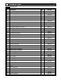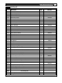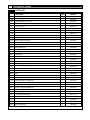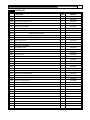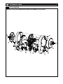
1
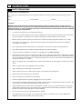
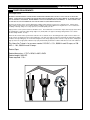
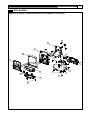
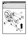
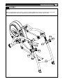
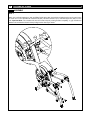
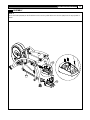
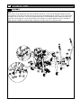
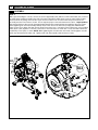
USER’S MANUAL CYBEX 350A HOME ARC TRAINER MODEL NUMBER: 350A USER WEIGHT LIMITATION: 300lbs (135 kg) SERIAL NUMBER (found on frame): P/N LT-20018-4 Revision B PS-MU-R350A-12-A3 2 350A HOME ARC TRAINER SAFETY PRECAUTIONS For future service or related questions: Please staple your receipt and/or write in the name and phone number of the retail store where you purchased your Home Arc Trainer. Name: ______________________________ Phone Number: ___________________ Receipt: ______________________ Precautions: WARNING: Failure to Read and Follow the following Precautions could result in Serious Injury! To reduce the risk of burns, fire, electric shock, or injury to persons, read the following important precautions and information before operating the Home Arc Trainer. It is the responsibility of the owner to ensure that all users of this Home Arc Trainer are adequately informed of all warnings and precautions. • Use the Home Arc Trainer only as described in this manual. • Place on a level surface, with 6 feet (2 m) of clearance behind it. Do not place the Home Arc Trainer on any surface that blocks air openings. To protect the floor or carpet from damage, place a mat under the Home Arc Trainer. • When choosing a location for the Home Arc Trainer make sure that the location and position permit access to a plug. • Keep the Home Arc Trainer indoors, away from moisture and dust. Do not put the Home Arc Trainer in a garage or covered patio, or near water. • Do not operate the Home Arc Trainer where aerosol products are used or where oxygen is being administered. • Keep children under the age of 12 and pets away from the Home Arc Trainer at all times. • The Home Arc Trainer should not be used by persons weighing more than 300 lbs (135 kgs) • Never allow more than one person on the Home Arc Trainer at a time. Wear appropriate exercise clothing when using the Home Arc Trainer. Do not wear loose clothing that could become caught in the Home Arc Trainer. Athletic support clothes are recommended for both men and women. Always wear athletic shoes. Never use the Home Arc Trainer with bare feet, wearing only stockings, or in sandals. • When connecting the power cord, plug the power cord into a grounded circuit. No other appliance should be on the same circuit. • Obtain a medical exam before beginning any exercise program. • Stop exercising if you feel faint, dizzy or experience pain. • Always examine your Home Arc Trainer before using to ensure all parts are in working order. • Allow the foot plates to fully stop before dismounting. • Never insert any object or body parts into any opening. • Follow the safety information in regards to plugging in your Home Arc Trainer. • Keep the power cord away from the incline wheels and do not run the power cord underneath your Home Arc Trainer. Do not operate the Home Arc Trainer with a damaged or frayed power cord. • Always unplug the Home Arc Trainer before cleaning and/or servicing. Service to your Home Arc Trainer should only be performed by an authorized service representative, unless authorized and/or instructed by the manufacturer. Failure to follow these instructions will void the Home Arc Trainer warranty. • Never leave the Home Arc Trainer unattended while it is running. • The equipment is for Home Use Only. Use of the Home Arc Trainer in a commercial, hotel, or other setting than an individual home will void all warranties and could cause injury. www.cybexinternational.com 3 POWER REQUIREMENTS Power Requirements: IMPROPER CONNECTION OF THE EQUIPMENT GROUNDING CONNECTOR CAN RESULT IN A RISK OF AN ELECTRIC SHOCK. CHECK WITH A QUALIFIED ELECTRICIAN OR SERVICE PROVIDER IF YOU ARE IN DOUBT AS TO WHETHER THE UNIT IS PROPERLY GROUNDED. DO NOT MODIFY THE PLUG PROVIDED WITH THE PRODUCT. IF THE PLUG WILL NOT FIT THE OUTLET; HAVE A PROPER OUTLET INSTALLED BY A QUALIFIED ELECTRICIAN. The Home Arc Trainer can be seriously damaged by sudden voltage changes in your home’s electrical power. Voltage spikes, surges and noise interference can result from weather conditions or from other appliances being turned on or off. To reduce the possibility of damage, always use a surge protector (not included) with your unit. Surge protectors can be purchased at most hardware stores. The manufacturer recommends a single outlet surge protector with a UL 1449 rating as a Transient Voltage Surge Suppressor (TVSS) with a UL suppressed voltage rating of 400V or less and an electrical rating 120VAC, 15 amps. This Home Arc Trainer must be grounded to reduce the risk of electrical shock. Grounding provides a path of least resistance for electric current, should the Home Arc Trainer malfunction. This unit comes with an electrical cord having an equipment-grounding conductor and a grounding plug. As shown in the diagrams below, always plug the power cord into a surge protector, and plug the surge protector into an appropriate outlet that is properly installed and grounded in accordance with all local codes and ordinances. This Home Arc Trainer is for use on a nominal 115 VAC +/- 5%, 50/60 Hz and 15 amps; or 230 VAC +/- 10%, 50/60 Hz and 10 amps. Product Spec: Product dimensions : L70.7 x W28.5 x H62.3 INCH Product weight: 300 LBS. Power required : 110 v 4 350A HOME ARC TRAINER PREASSEMBLY Open the boxes: As you open each box, take inventory of all items contained inside the box. Use the “Content Checklist” and “Hardware Comparison Chart” located on the following pages to assist you in taking inventory of each box. If you are missing any parts or have any assembly questions call your local Cybex Retailer or Cybex Customer Service 1-888-462-9239. Gather your tools: Before starting the assembly, gather all the necessary tools you need to assemble the unit properly. Clear your work area: Make sure that your work area is free and clear from all objects that may cause injury during assembly. After the unit is fully assembled, allow enough clearance for safe access and operation. Invite a friend: For assembly steps that require heavy lifting, use a minimum of two people to lift, move and assemble this unit. User Weight Limitation: Do not use this unit if you weigh more than 300 lbs (135 kg). This is the rated maximum user weight. Serious injury may occur if the user’s weight exceeds 300 lbs (135 kg). Care and maintenance: 1. The safety level of the Home Arc Trainer can be maintained only if it is examined regularly for damage and wear. 2. Replace defective components immediately and stop the use of the equipment until it is repaired. 3. Always be careful when mounting or dismounting the equipment. Use the handles to steady yourself before starting your workout. Dismount from the equipment only after you have come to a complete stop. 4. Always check your Home Arc Trainer for any worn parts or torn or damaged labels. If any parts are broken or labels missing, please call Cybex Customer Service. Cleaning Your Home Arc Trainer: After each use: 1. Wipe up any liquid spills immediately. 2. Use a cloth to wipe up any remaining perspiration from the handles and painted surfaces. As Needed: 1. Clean your unit using a spray a mild cleaning agent, such as a water and dish soap solution, on a clean cloth first and then wipe the unit with a damp cloth. NOTE: Do not spray cleaning solution directly on the unit. Direct spraying could cause damage to the electronics and may void the warranty. 2. Vacuum any dust or dirt that might accumulate under or around the unit. Heart Rate Grips Contaminants, such as hand lotions, oils or body powder may come off on the contact heart rate grips. These can reduce sensitivity and interfere with the heart rate signal. It is recommended that you use clean hands when using the contact heart rate. Clean the heart rate grips periodically as noted below. 1. Clean heart rate grips using a cloth dampened with a cleaning solution containing alcohol. The grips are the only part of the unit you should use a cleaning solution containing alcohol. www.cybexinternational.com CONTENTS CHECKLIST Carton contents: For your convenience, we have identified the contents of the shipping carton. Please check to make sure you have all of the components before assembly. This chart is provided to help you identify the components used in the assembly of this product. No. Description Qty. Computer set 1 Box A Box B 1 513 Adjustable foot stand M8 2 321 Handlebar bottom bushing 2 351 Handlebar front end-upper 1 352 Handlebar front end-bottom 1 353 Water bottle cover-outer left 1 354 Water bottle cover-inner left 1 355 Water bottle cover-outer right 1 356 Water bottle cover-inner right 1 362 Water bottler insert 2 360 Console mount cover-front 2 361 Console mount cover-back 2 521 Power cord 1 624 Chest belt 1 Hardware kit 1 A Box C A BOX 513 353 521 321 351 352 354 624 355 362 356 360 361 A 1 B BOX 358 Foot pedal cover-left 1 359 Foot pedal cover-right 1 358 359 C BOX 5 6 350A HOME ARC TRAINER HARDWARE COMPARISON CHART Hardware chart: For your convenience, we have identified the hardware used in the assembly of this product. This chart is provided to help you identify those items that may be unfamiliar to you. No. Description Qty. 501 Flat hex head bolt M8x16 4 502 Button head cap screw M6x16 2 503 M8x25 Bolt 6 504 M10x70 Bolt 2 505 Crank bushing 35X35 mm 2 506 M4x15 Screw 8 507 M4x19 Screw 4 508 M10 Nylon Nut 2 509 φ16 x 6 x T2 washer 2 510 φ32 x 8 x T2.0 washer 4 511 φ26 x12XT3.0 washer 2 512 φ26x 10XT2.0 washer 2 514 Self tapping screw M4X12 8 515 φ19x8xT1.6 Curve Washer 4 516 M8 Spring washer 4 A Phillips Head Wrench 1 B M5 Allen wrench 1 C M4 Allen wrench 1 D 17mm Spanner 1 E 19mm Spanner 1 514 501 505 510 507 506 511 512 A 508 515 B D MILLIMETERS 504 503 502 509 516 C E www.cybexinternational.com PARTS LIST Description Qty. Order No. 101 Main frame 1 350A-101 105 Front linkage-left 1 350A-105 106 Front linkage-right 1 350A-106 109 Moving Linkage-left 1 350A-109 110 Moving Linkage -right 1 350A-110 116 Console support bracket 1 350A-116 A01 Fly wheel set 1 350A-A01 A02 Left handlebar set 1 350A-A02 A03 Right handlebar set 1 350A-A03 A04 Back linkage-left 1 350A-A04 A05 Back linkage-right 1 350A-A05 A06 Rear support leg 2 350A-A06 A07 Arm linkage 2 350A-A07 A08 Foot support tube assembly-right 1 350A-A08 A09 Foot support tube assembly-left 1 350A-A09 A10 Water bottle cover-left 1 350A-A10 A11 Water bottle cover-right 1 350A-A11 A12 Power switch set 1 350A-A12 A13 Console insert 1 350A-A13 202 Bearing 6804 4 350A-202 205 Bearing 2205 4 350A-205 206 Bearing 6001 4 350A-206 208 Bearing 6205 2 350A-208 209 Bearing BL-6206 2 350A-209 210 Tolerance ring AN28-(ID28xT8) 4 350A-210 211 Tolerance ring AN32-(ID32xT7) 4 350A-211 214 Tolerance ring AN52-(ID52xT18) 4 350A-214 216 Front linkage bushing 35x16--ID15 2 350A-216 217 Drive linkage bushing 45x23--ID5 2 350A-217 221 Moving wheel 2 350A-221 223 Drive linkage axel 45x59-(25x36)-M8 2 350A-223 224 Front linkage axel 35x41-(15x20)-M6 2 350A-224 225 Oval tube cap 2 350A-225 230 Plastic cover insert 12 350A-230 7 8 350A HOME ARC TRAINER PARTS LIST Description Qty. Order No. 302 Console cover-upper 1 350A-302 303 Console cover-bottom 1 350A-303 304 Console tray-upper 1 350A-304 305 Console tray-bottom 1 350A-305 306 Main cover-left 1 350A-306 307 Main cover-right 1 350A-307 309 Incline motor cover-left 1 350A-309 310 Incline motor cover-right 1 350A-310 311 Pulley cover 2 350A-311 313 Rear support leg bottom cover-inner 2 350A-313 314 Rear support leg bottom cover-outer 2 350A-314 316 Back linkage end cap 2 350A-316 317 Drive linkage rear axel cover 2 350A-317 318 Front linkage axel cover 2 350A-318 320 Back linkage bushing ring 2 350A-320 321 Handlebar bottom bushing 2 350A-321 350A-323 351 Moving wheel cover Handlebar front end-upper 2 1 350A-351 352 Handlebar front end-bottom 1 350A-352 357 Foot pedal cover-upper 2 350A-357 358 Foot pedal cover-left 1 350A-358 359 Foot pedal cover-right 1 350A-359 360 Console mount cover-front 2 350A-360 402 Flat hex head bolt M8x16 8 350A-402 407 Button head cap screw M5x10 4 350A-407 409 Button head cap screw M6x16 6 350A-409 411 2 350A-411 422 Button head cap screw M10x50 Button head M5x35 4 350A-422 423 Button head M5x45 2 350A-423 427 2 350A-427 432 Nylon nut M10 Arm linkage axel 2 350A-432 433 Back linkage axel 2 350A-433 434 Foot support axel 2 350A-434 435 Phillips head M4x15 20 350A-435 437 Phillips head M4x15 20 350A-437 350A-441 447 R clip Washer 30x8xT2.0 4 4 350A-447 448 Washer 27x8xT2.0 4 350A-448 451 Washer 20x6xT1.5 2 350A-451 452 Bushing 12x8x6 2 350A-452 454 Phillips head M4x25 1 350A-454 323 441 www.cybexinternational.com PARTS LIST Description Qty. Order No. 501 Flat hex head bolt M8x16 4 350A-501 502 Button head cap screw M6x16 2 350A-502 503 Button head cap screw M8x25 6 350A-503 504 Bolt M12x70 2 350A-504 505 Crank bushing 35x35 2 350A-505 506 Allen head screw M4x15 8 350A-506 507 Allen head screw M4x19 4 350A-507 508 Nylon nut M10 2 350A-508 509 Washer 16x6xT2 2 350A-509 510 Washer 30x8xT2.0 4 350A-510 511 Washer 26x12xT3.0 2 350A-511 512 Washer 26x10xT2.0 2 350A-512 513 Adjustable foot stand M8 2 350A-513 514 Allen head screw M4x12 8 350A-514 515 19x8xT1.6 Curve Washer 4 350A-515 516 M8 Spring washer 4 350A-516 Phillips Hand Wrench 1 350A-A A B M5 Allen wrench 1 350A-B C M4 Allen wrench 1 350A-C D 17min Spanner 1 350A-D E 19mm Spanner 1 350A-E 350A-521 610 Power code 12Pin power wire-upper 1 1 350A-610 615 4P hand pulse signal wire-upper 1 350A-615 621 Heart rate grommet 2 350A-621 103 321 Left handlebar frame 1 Handlebar bottom bushing ring 1 350A-103 350A-321 207 Bearing 6005 2 350A-207 213 Tolerance ring AN47-(ID47xT12) 2 350A-213 501 Flat hex head bolt M8x16 1 350A-501 510 Washer 30x8xT2.0 1 350A-510 521 Left handlebar set A02 Right handlebar set A03 104 321 Right handlebar frame 1 Handlebar bottom bushing ring 1 350A-104 350A-321 207 Bearing 6005 2 350A-207 213 Tolerance ring AN47-(ID47xT12) 2 350A-213 501 Flat hex head bolt M8x16 1 350A-501 510 Washer 30x8xT2.0 1 350A-510 Back linkage-left A04 107 Back linkage-left 1 350A-107 312 Foot support tube axel cover 1 350A-312 9 10 350A HOME ARC TRAINER PARTS LIST Description Qty. Order No. 108 Back linkage-right 1 350A-108 312 Foot support tube axel cover 1 350A-312 1 350A-111 1 350A-324 A05 Back linkage-right A06 111 324 Rear support leg Rear support leg Rear support leg stand A07 Arm linkage 113 Arm linkage 1 350A-113 206 Bearing 6001 1 350A-206 210 Tolerance ring AN28-(ID28xT8) 1 350A-210 361 Console mount cover-back 1 350A-361 439 R clip 1 350A-439 502 Button head cap screw M6x16 1 350A-502 509 Washer 20x6xT1.5 1 350A-509 A08 Foot support tube assembly-right 114 Foot support tube assembly-right 1 350A-114 203 Bearing 2202 1 350A-203 207 Bearing 6005 2 350A-207 212 Tolerance ring AN35-(ID35xT14) 1 350A-212 213 Tolerance ring AN47-(ID47xT12) 2 350A-213 315 Front linkage top axel cover 1 350A-315 319 Front linkage bushing ring 1 350A-319 402 Flat hex head bolt M8x16 1 350A-402 435 Phillips head M4x15 1 350A-435 440 R clip 1 350A-440 447 Washer 30x8xT2.0 1 350A-447 A09 Foot support tube assembly-left 115 Foot support tube assembly-left 1 350A-115 203 Bearing 2202 1 350A-203 207 Bearing 6005 2 350A-207 212 Tolerance ring AN35-(ID35xT14) 1 350A-212 213 Tolerance ring AN47-(ID47xT12) 2 350A-213 315 Front linkage top axel cover 1 350A-315 319 Front linkage bushing ring 1 350A-319 402 Flat hex head bolt M8x16 1 350A-402 435 Phillips head M4x15 1 350A-435 440 R clip 1 350A-440 447 Washer 30x8xT2.0 1 350A-447 www.cybexinternational.com PARTS LIST Description Qty. Order No. 353 Water bottle cover-outer left 1 350A-353 354 Water bottle cover-inner left 1 350A-354 230 Plastic cover insert 3 350A-230 506 Allen head screw M4x15 4 350A-506 507 Allen head screw M4x19 Water bottler insert 1 350A-507 1 350A-362 355 Water bottle cover-outer right 1 350A-355 356 Water bottle cover-inner right 1 350A-356 230 Water bottle cover-left A10 362 Water bottle cover-right A11 Plastic cover insert 3 350A-230 506 Allen head screw M4x15 4 350A-506 507 Allen head screw M4x19 Water bottler insert 1 350A-507 1 350A-362 362 Power switch set A12 233 Power switch bracket 1 350A-233 308 Power input set\ 1 350A-308 408 Button head cap screw M5x25 2 350A-408 421 Button head M3x6 2 350A-421 424 Nut M5 2 350A-424 601 Power insert set 1 350A-601 602 Fuse 1 350A-602 603 Power switch 1 350A-603 A13 Console insert 301 Console insert with PC board 1 350A-301 436 8 350A-436 608 Phillips head M3x12 Computer overlay-upper 1 350A-608 609 Computer overlay-bottom 1 350A-609 11 12 350A HOME ARC TRAINER PARTS DIAGRAM A MAJORITY OF THE PARTS SHOWN HERE HAVE BEEN PRE-ASSEMBLED AT THE FACTORY. 501 452 360 510 441 205 214 516 503 515 A06 A02 503 214 205 441 A03 516 515 A07 510 360 452 501 A06 A07 435 314 435 313 314 435 313 www.cybexinternational.com 13 PARTS DIAGRAM A MAJORITY OF THE PARTS SHOWN HERE HAVE BEEN PRE-ASSEMBLED AT THE FACTORY. A11 A10 447 433 455 209 402 357 402 208 101 447 A05 512 512 422 223 206 402 447 209 206 214 205 441 320 357 506 511 455 433 208 447 508 359 504 210 317 423 506 432 110 210 504 202 320 441 205 214 402 202 217 448 402 318 448 223 211 437 A06 511 432 358 106 202 211 318 109 423 437 402 448 217 422 621 317 621 A08 105 224 225 224 216 409 216 451 A09 451 323 323 225 513 427 411 221 411 402 14 350A HOME ARC TRAINER PARTS DIAGRAM A MAJORITY OF THE PARTS SHOWN HERE HAVE BEEN PRE-ASSEMBLED AT THE FACTORY. 407 454 434 230 434 505 437 505 437 311 407 435 435 435 311 307 435 230 A12 310 A01 437 309 437 306 www.cybexinternational.com 15 PARTS DIAGRAM A MAJORITY OF THE PARTS SHOWN HERE HAVE BEEN PRE-ASSEMBLED AT THE FACTORY. 409 116 303 302 437 503 A13 352 230 304 610 507 351 230 615 305 437 16 350A HOME ARC TRAINER ASSEMBLY STEP 1: Open box, remove the three (3) accessories boxes positioned between the foot pedals and set aside. Remove arms and set aside. Remove the zip tie which tightens the frame on the wooden rack and remove the wooden rack. Determine location of use for the 350A Home Arc Trainer and lift main frame (101) out. Note: It is recommended that two people lift the main frame out of the box. Remove all other packing material from the frame. Lift the back end up as shown. 101 www.cybexinternational.com ASSEMBLY STEP 2: With back end elevated, insert Left Rear Support Leg (A06) and Right Rear Support Leg (A06) into the frame and secure with M8x25 Allen bolts (503), Spring washer (516) and Washer (515) on each side as shown. 516 503 515 516 503 515 A06 17 18 350A HOME ARC TRAINER ASSEMBLY STEP 3: Attach the Left Pedal Swing Arm (106) and Right Pedal Swing Arm (105) with the pivoting bracket on the main frame as shown and secure with M12x70 shoulder bolt (504), 26x12xT3.0 washer (511) and M12 Nylon Nut (508) on each side. Important Note: The shoulder bolt must be inserted into the pivoting bracket completely, no gap should exist between the shoulder bolt head and the pivoting bracket. See Figure below. 504 511 512 508 512 511 105 504 106 www.cybexinternational.com 19 ASSEMBLY STEP 4: Place the Pedal (359,358) on the Pedal Arm and secure the pedal with 4-4x15 Screws (506) from the top of pedal as shown. A08 506 A09 358 506 359 20 350A HOME ARC TRAINER ASSEMBLY STEP 5: Place spacers on the right and left side of the handlebar shaft (321). Line up the Left Handlebar (A02) lower pivot housing with the shaft on the main frame and the shaft on the Left Handlebar with the Linkage (113), then push both pivot joints in at the same time. Secure the handlebar with Flat hex head bolt M8x16 (501) and Washer 30x8xT2.0 (510) on the lower pivot joint. Secure the handle bar to the Linkage (113) with the Button head cap screw M6x16 (502), Cap (361) and Washer 16x6xT2 (509). Repeat the same procedure for the right hand side. www.cybexinternational.com 21 ASSEMBLY STEP 6: Rotate the Left Crank to the lowest position as shown below. Important Note: Failure to rotate the crank arm to the proper position will not allow the unit to be assembled properly. Place the Crank Bushing (505) on the Left Crank Shaft (434) and then mount the Left Crank-Pedal Link Bar (110) on the left crank shaft, attach the Cap (360) on and secure with M8x16 Flat Allen head bolt (501) as shown. Repeat the same procedure on the right hand side. 22 350A HOME ARC TRAINER ASSEMBLY STEP 7: With a person holding the console, connect the 12 Pin Upper Cable (610) with the 12 Pin Lower Cable (611). Connect the 4 Pin Upper Hand Pulse Cable (615) and 4 Pin Lower Hand Pulse Cable (616), Insert the extra length of cables into the Console Assembly and insert the 12 pin connector into the hole on Front Tower then place the Console Assembly onto the Front Tower as shown. Ensure tight and proper connection between the cables. Important Note: The half-round hole on the Console Assembly bottom bracket must match with the pins welded on the Front Tower before tightening the Console Assembly with the Front Tower. Secure the Console Assembly with 2 M8x25 Bolts (503). Insert 6 pieces Nylon Pin (230) into the Front Tower Cover (351 ), mount the Front Tower Cover (351) and Rear Tower Cover ( 352) together to cover the connection at the main frame as shown then secure them with 2 4x19 Flat Head Philip screws (507) as shown. NOTE: When tightening the console to the main frame, Do Not tighten one side all the way down before the other side. Tighten each side down equally small amounts at a time. 116 352 615 616 610 611 503 351 507 www.cybexinternational.com 23 ASSEMBLY STEP 8: Insert 3 pieces Nylon Pin (230) into the Left/Outer Frame Join Cover (356 ), mount the Left/Outer and Left/Inner Frame Join Cover (355 ) to cover the left hand side frame joint and secure them with 4 -4x15 taper screws (514) and 2 -4x19 Flat Head Philip screws (507). See Figure below. Repeat the same procedure for the right hand side frame joint. 362 514 230 514 355 356 507 A10 101 514 362 514 507 230 354 353 A10 A11 A11 24 350A HOME ARC TRAINER ASSEMBLY STEP 9: Lift the front end and attach the Level Adjustment (513) underneath the front stabilizer tube. Level the Home Arc Trainer so it does not move or rock. All assembly steps are now completed. Plug unit into a dedicated wall outlet. NOTE: The Home Arc Trainer should be plugged into a dedicated line or circuit. 101 513 www.cybexinternational.com COMPUTER OPERATION CM-EC-M350A-2 CM-EC-M350A-21 25 26 350A HOME ARC TRAINER COMPUTER OPERATION M A N O P Q R B CM-EC-M350A-2 S C D E T U CM-EC-M350A-21 F G H I J K L SCAN A B CHOOSE PROGRAM Buttons INCLINE UP C D PAUSE/END INCLINE DOWN E F DISTANCE CALORIES G H CAL/hr METs I J DISTANCE CLIMBED STRIDES/min K L HEART RATE ENTER M N TIME ADJUSTMENT BUTTON-UP O P LEVEL ADJVSTMENT BUTTON-DOWN Q R WEIGHT RESISTANCE UP S T QUICK START RESISTANCE DOWN U www.cybexinternational.com 27 COMPUTER OPERATION Cybex 350A Home Arc Trainer console operating instruction manual Buttons: Program Buttons: Manual: Program button. Press to select P1 manual adjustment program. Calories: Program button. Press to select P2 target calories burns program. Random: Program button. Press to select P3 Random workout program. Fitness: Program button. Press to select 3 Fitness programs : P4 – Weight Loss program. P5 – Cardio Program. P6 – Endurance Program. Hills: Program button. Press to select 3 Hills programs : P7 – Hill Program P8 – Valleys Program P9 – Ramps Program. Interval: Program button. Press to select 3 Interval programs : P10 – Interval 2 to 1 program. P11 – Interval 1 to 1 program. P12 – Hill Interval program. Data Display Control buttons: Scan: Press to display all workout data revolving on the center LED display window during the workout. Functions activate when Scan LED lights on. When each data showing on the center LED window, the corresponds button LED will be on at the same time. Dist.: Press to deactivate other data display functions and show accumulated workout distance on center LED display window during the workout. Function activates when Dist. LED lights on. Cal.: Press to deactivate other data display functions and show accumulated calories burns on center LED display window during the workout. Function activates when Cal. LED lights on. Cal/Hr.: Press to deactivate other data display function and shows the average calories burns per hour on center LED display window during the workout. Function activates when Cal/Hr. LED lights on. Distance Climbed: Press to deactivate other data display functions and shows current climbed distance on center LED display window during the workout. Function activates when Distance Climbed LED lights on. Strides per Minute: Press to deactivate other data display function and shows the workout speed by Strides per minute on center LED display window during the workout. Function activate when Strides per Minute LED lights on. 28 350A HOME ARC TRAINER COMPUTER OPERATION Heart Rate: Press to deactivate other data display functions and show the workout heart rate on the center LED display window during the workout. Function activates when Heart Rate LED lights on. Workout Control Buttons : Enter: Press to confirm the input workout Time, Level and user Weight during workout program set up procedure. Up Arrow: Press to increase the workout Time, Level and User Weight during workout program set up procedure. Down Arrow: Press to decrease the workout Time, Level and User Weight during workout program set up procedure. Time: Press to select workout time and adjustment. Level: Press to select workout level and adjustment. Weight: Press to select user weight and adjustment. Quick Start: Press to activate the Quick Start program.. Resistance +: Press to increase the resistance level during the workout. Resistance -: Press to reduce the resistance level during the workout. Pause / End: Press to pause or end the program during workout. Press once to pause the program, press twice to enter the Dormant State. www.cybexinternational.com 29 COMPUTER OPERATION Incline +: Press to increase the incline level during the workout.. Incline -: Press to decrease the incline level during the workout. OPERATING INSTRUCTIONS: Dormant State: Connect the power cord, turn on the power switch located at front end, LED dot matrix display shows Cybex logo for 3 seconds and then enters the Dormant State. Before stepping on the pedal or pressing any program buttons including the Quick Start button, the unit will stay in the Dormant State. All LED windows are off except the LED dot matrix display which shows the blinking heart sign and 6 program buttons LED indication lights on and off in rotation. While on the Dormant State, you can press the Quick Start button to start the workout, or press any program button to start configuring the program or directly stepping the pedal for 20 seconds to start the workout. If pressing any other buttons, a beep will be sounded and the LED dot matrix display will show an arrow sign to point the program button’s direction. Program State: While on the Dormant or Active State, press one of the 6 program buttons then press the Enter button. The Home Arc Trainer will be entered into the Program State. Follow the program set up instructions to complete the program configuration and start the workout. User must press the Enter button after completing the program set up in order to store all the data into the console for the workout. Failure to press the Enter button will result in all the set up data being lost and the Home Arc Trainer not entering the Active State. If the Start button is pressed without pressing the Enter button first, the Home Arc Trainer will perform the Quick Start function at the default user weight of 150 lb ( 68 kgs ) and default workout time of 20 minutes. Active State: While on the Dormant State, press Quick Start or begin stepping on the pedals for 20 seconds. The Home Arc Trainer will be entered into the Active State. Or press any of the program buttons, complete the program setup procedure and start the workout and the Home Arc Trainer will be also entered the Active State. The Active State will be ended when the Pause/End button is pressed during the workout or the preset workout time is up. Review State: After completing the Active State, the display will be entered into the Review State for the user to review the workout result. The review state period lasts for 20 seconds. After 20 seconds, the Home Arc Trainer will be entered into the Dormant State automatically. Quick Start: While in Dormant State, press Quick Start button to start the workout. The time display will count up and the user weight is based on the default setting of 150 lb (68 KGS). Program Set Up and Operating: Manual: While in the Dormant State, press the Manual button. The center LED window will show “P1”. Press the Enter button (If the Enter button is not pressed within 10 seconds, this procedure will be skipped to the next step, user weight set up), and the center LED window will then show the default user weight “150” (LB) while the LED dot matrix window shows “LBS”. Press the Up or Down Arrow buttons to set up user weight and then press Enter (If the Enter button is not pressed within 10 seconds, this procedure will be skipped to the next step workout time, set up), and the center LED window shows default workout time “20”(Minutes) and the LED dot matrix window shows “MIN”. Press the Up or Down Arrow buttons to set up the target workout time then press the Enter button to start the workout. The center LED window starts counting down 3 seconds then starts the manual program. Time counts down from the set workout time to 0:00. During the workout, the user can press the Incline + and Incline – buttons to adjust the incline level from 0 to 10 and press Resistance + and Resistance – buttons to adjust the resistance level from 1 to 20. 30 350A HOME ARC TRAINER COMPUTER OPERATION Calorie: While on the Dormant State, press the Calories button. The center LED window shows “P2”. Press the Enter button and the center LED window then shows “0” while the LED dot matrix window shows “CAL”. Press the Up or Down Arrow buttons to set up the target calories from 20 up to 9999. Then press Enter and the center LED window then shows the default user weight “150” (LB) while the LED dot matrix window shows “LBS”. Press the Up or Down Arrow buttons to set up user weight. Then press Enter and the center LED window starts to count down 3 seconds before beginning the Calories program. Time counts up from 0:00 and Calories counts up to the set up target calories. During the workout, the user can press the Incline + and Incline – button to adjust the incline level from 0 to 10. Press the Resistance + and Resistance – buttons to adjust the resistance level from 1 to 20. Random: While on the Dormant State, press the Random button. The center LED window shows “P3”. Press the Enter button (If the Enter button is not pressed within 10 seconds, this procedure will be skipped to the next step, user weight set up) and the center LED window then shows the default user weight “150” (LB). The LED dot matrix window shows “LBS”. Press the Up or Down Arrow buttons to set up user weight. Then press Enter (If the Enter button is not pressed within 10 seconds, this procedure will be skipped to the next step, workout time set up) and the center LED window shows default workout time “20”(Minutes). The LED dot matrix window shows “MIN”. Press the Up or Down Arrow buttons to set up target workout time and then press the Enter button. The center LED window shows workout level “1” and the LED dot matrix window shows “LVL”. Press the Up and Down Arrow buttons to select the workout level from 1 to 10 and then press the Enter button to start the workout. The center LED window starts the count down for 3 seconds and then starts the Random program. Time counts down from set up workout time to 0:00. During the workout, the user can press the Incline + and Incline – buttons to overwrite the preset profile and adjust the incline level from 0 to 10. Press Resistance + and Resistance – buttons curing the workout to overwrite the preset profile and adjust the resistance level from 1 to 20. The overwrite will only last for one segment of workout and then the next segment will return to the original preset profile. Fitness Programs: While on the Dormant State, press Fitness button. The center LED window shows “P4”. Press the Enter button to select P4 and start the user weight set up. Or press the Up or Down Arrow buttons to select among P4 to P6. Then press the Enter button to start the user weight set up (If the Enter button is not pressed within 10 seconds, this procedure will be skipped to the next step, user weight set up) and the center LED window then shows the default user weight “150” (LB) while the LED dot matrix window shows “LBS”. Press the Up or Down Arrow buttons to set up user weight then press Enter (If the Enter button is not pressed within 10 seconds, this procedure will be skipped to the next step, workout time set up) and the center LED window shows default workout time “20”(Minutes) while the LED dot matrix window shows “MIN”. Press the Up or Down Arrow buttons to set up the target workout time and then press the Enter button. The center LED window shows workout level “1” and the LED dot matrix window shows “LVL”. Press the Up and Down Arrow buttons to select the workout level from 1 to 10 and then press the Enter button to start the workout. The center LED window starts count down 3 seconds before starting the selected Fitness program. Time counts down from set up workout time to 0:00. During the workout, the user can press the Incline + and Incline – buttons to overwrite the preset profile and adjust the incline level from 0 to 10. Press the Resistance + and Resistance – buttons during the workout to overwrite the preset profile and adjust the resistance level from 1 to 20. The overwrite will only last for one segment of workout and then the next segment will return to the original preset profile. (If the Enter button is not pressed within 10 seconds, this procedure will be skipped to the next step, user weight set up) and the center LED window then shows the default user weight “150” (LB) while the LED dot matrix window shows “LBS”. Press the Up or Down Arrow buttons to set up user weight and then press Enter (If the Enter button is not pressed within 10 seconds, this procedure will be skipped to the next step, workout time set up) and the center LED window shows default workout time “20”(Minutes) while the LED dot matrix window shows “MIN”. Press the Up or Down Arrow buttons to set up the target workout time and then press the Enter button. The center LED window shows workout level “1” and the LED dot matrix window shows “LVL”. Press the Up and Down Arrow buttons to select the workout level from 1 to 10 and then press the Enter button to start the workout. The center LED window will count down 3 seconds before the selected Fitness program begins. Time counts down from set up workout time to 0:00. During the workout, the user can press Incline + and Incline – buttons to overwrite the preset profile and adjust the incline level from 0 to 10. Press the Resistance + and Resistance – buttons to overwrite the preset profile and adjust the resistance level from 1 to 20. The overwrite will only last for one segment of workout and then the next segment will return to the original preset profile. www.cybexinternational.com 31 COMPUTER OPERATION P-4 Weight Loss The Weight Loss program is designed for low to medium intensity training that the user can sustain for an extended period of time. It builds from a low intensity baseline to include segments of higher incline and resistance as well as segments that use higher resistance at the base incline. The constant variety provides for periods of higher energy expenditure and training effect with less fatigue, allowing the user to exercise for longer periods of time. Time :30 :30 :30 :30 :30 :30 :30 :30 :30 :30 :30 :30 :30 :30 :30 :30 :30 :30 :30 :30 Refer to notes Distance Warm Up Program Segments Cool Down Resistance 1 2 3 4 1 2 3 4 5 6 7 8 9 10 11 12 1 2 3 4 10 1 2 3 4 5 5 9 9 9 9 5 5 9 9 5 5 4 3 2 1 9 1 2 3 4 5 5 8 8 8 8 5 5 8 8 5 5 4 3 2 1 8 1 2 3 4 5 5 7 7 7 7 5 5 7 7 5 5 4 3 2 1 7 1 1 2 3 5 5 8 8 8 8 5 5 8 8 5 5 3 2 1 1 6 1 1 2 3 5 5 7 7 7 7 5 5 7 7 5 5 3 2 1 1 5 1 1 2 3 5 5 6 6 6 6 5 5 6 6 5 5 3 2 1 1 4 1 1 1 2 3 3 5 5 5 5 3 3 5 5 3 3 2 1 2 2 3 1 1 1 2 3 3 4 4 4 4 3 3 4 4 3 3 2 1 2 2 2 1 1 1 1 1 1 3 3 3 3 1 1 3 3 1 1 1 1 1 1 1 1 1 1 1 1 1 2 2 2 2 1 1 2 2 1 1 1 1 1 1 Warm Up Program Segments Cool Down Incline 1 2 3 4 1 2 3 4 5 6 7 8 9 10 11 12 1 2 3 4 10 4 4 4 4 4 4 6 6 6 6 4 4 4 4 4 4 4 4 4 4 9 4 4 4 4 4 4 6 6 6 6 4 4 4 4 4 4 4 4 4 4 8 3 3 3 3 3 3 6 6 6 6 3 3 3 3 3 3 3 3 3 3 7 3 3 3 3 3 3 4 4 4 4 3 3 3 3 3 3 3 3 3 3 6 3 3 3 3 3 3 4 4 4 4 3 3 3 3 3 3 3 3 3 3 5 3 3 3 3 3 3 4 4 4 4 3 3 3 3 3 3 3 3 3 3 4 2 2 2 2 2 2 3 3 3 3 2 2 2 2 2 2 2 2 2 2 3 2 2 2 2 2 2 3 3 3 3 2 2 2 2 2 2 2 2 2 2 2 2 2 2 2 2 2 3 3 3 3 2 2 2 2 2 2 2 2 2 2 1 2 2 2 2 2 2 3 3 3 3 2 2 2 2 2 2 2 2 2 2 FITNESS –Cardio 32 350A HOME ARC TRAINER COMPUTER OPERATION P-5 Cardio The Cardio program is designed for experienced users that desire a high intensity cardiovascular training experience. The 2-minute work interval with high resistance ensures that the aerobic energy system is completely taxed, while the subsequent 2-minute recovery interval enables a repeat at the higher work rate. Additionally, a higher incline level is used during the recovery interval to discourage blood pooling ensuring more complete recovery. :30 :30 :30 :30 :30 :30 :30 :30 :30 :30 :30 :30 :30 Refer to notes :30 :30 :30 Refer to notes Warm Up Program Segments Cool Down 1 2 3 4 1 2 3 4 5 6 7 8 1 2 3 4 6 7 9 11 16 16 16 16 12 12 12 12 11 9 7 6 5 7 9 11 15 15 15 15 11 11 11 11 11 9 7 5 5 6 8 9 14 14 14 14 10 10 10 10 9 8 6 5 4 5 7 8 13 13 13 13 9 9 9 9 8 7 5 4 3 4 6 7 12 12 12 12 8 8 8 8 7 6 4 3 3 4 5 6 11 11 11 11 7 7 7 7 6 5 4 3 2 3 4 5 10 10 10 10 6 6 6 6 5 4 3 2 1 2 3 4 9 9 9 9 6 6 6 6 4 3 2 1 1 1 2 3 8 8 8 8 5 5 5 5 3 2 1 1 1 1 1 2 7 7 7 7 4 4 4 4 2 1 1 1 Warm Up Program Segments Cool Down 1 2 3 4 1 2 3 4 5 6 7 8 1 2 3 4 3 4 5 6 5 5 5 5 8 8 8 8 6 5 4 3 3 3 4 5 5 5 5 5 8 8 8 8 5 4 3 3 3 3 4 4 5 5 5 5 7 7 7 7 4 4 3 3 3 3 4 4 4 4 4 4 7 7 7 7 4 4 3 3 3 3 3 4 4 4 4 4 6 6 6 6 4 3 3 3 3 3 3 3 4 4 4 4 6 6 6 6 3 3 3 3 2 2 2 3 3 3 3 3 5 5 5 5 3 2 2 2 2 2 2 3 3 3 3 3 5 5 5 5 3 2 2 2 2 2 2 2 2 2 2 2 4 4 4 4 2 2 2 2 2 2 2 2 2 2 2 2 4 4 4 4 2 2 2 2 www.cybexinternational.com 33 COMPUTER OPERATION P-6 Endurance The Endurance program challenges the cardiovascular system in a manner that adjusts the overall intensity to accommodate for fatigue but maintains a similar perceived exertion throughout the workout. The core program is 16 minutes in length. After warmup the intensity is increased over the next four minutes. Peak intensity is maintained for the next two minutes and then gradually tapers off during the following ten minutes. :30 :30 :30 :30 1:00 1:00 1:00 1:00 1:00 1:00 1:00 1:00 1:00 1:00 1:00 1:00 1:00 1:00 1:00 1:00 :30 :30 :30 :30 Refer to notes Refer to notes Resistance Warm Up Elevation Refer to notes Program Segments 4 Cool Down 1 2 3 1 2 3 4 5 6 7 8 9 10 11 12 13 14 15 16 2 3 4 4 6 8 10 12 16 16 20 20 20 18 18 18 16 16 16 14 14 14 12 10 8 6 4 4 6 8 9 11 15 15 19 19 19 17 17 17 15 15 15 13 13 13 11 9 8 6 4 4 6 7 8 10 14 14 18 18 18 16 16 16 14 14 14 12 12 12 10 8 7 6 4 3 5 7 7 9 13 13 17 17 17 15 15 15 13 13 13 11 11 11 9 7 7 5 3 3 5 6 7 8 12 12 16 16 16 14 14 14 12 12 12 10 10 10 8 7 6 5 3 3 5 6 6 7 11 11 15 15 15 13 13 13 11 11 11 9 9 9 7 6 6 5 3 2 4 5 6 6 10 10 14 14 14 12 12 12 10 10 10 8 8 8 6 6 5 4 2 2 4 5 5 5 9 9 13 13 13 11 11 11 9 9 9 7 7 7 5 5 5 4 2 2 3 4 5 4 8 8 12 12 12 10 10 10 8 8 8 6 6 6 4 5 4 3 2 2 2 3 3 3 7 7 11 11 11 9 9 9 7 7 7 5 5 5 3 3 3 2 2 Warm Up Program Segments 1 Cool Down 1 2 3 4 1 2 3 4 3 4 5 6 8 10 10 10 10 10 10 10 10 10 10 10 9 9 9 3 3 4 5 7 9 9 10 10 10 9 9 9 9 9 9 8 8 8 8 6 5 4 3 7 5 4 3 3 3 4 4 7 9 9 9 9 9 9 9 9 9 9 9 8 8 3 8 7 4 4 3 3 3 3 4 4 6 8 8 9 9 9 8 8 8 8 8 8 7 3 3 3 4 6 8 8 8 8 8 8 8 8 8 8 8 7 7 7 6 4 4 3 3 7 7 6 4 3 3 3 3 3 3 3 5 7 7 8 8 8 7 7 7 7 7 7 2 2 2 3 5 7 7 7 7 7 7 7 7 7 7 7 6 6 6 5 3 3 3 3 6 6 6 5 3 2 2 2 2 2 2 3 4 6 6 7 7 7 6 6 6 6 6 2 2 2 2 4 6 6 6 6 6 6 6 6 6 6 6 5 5 5 4 3 2 2 2 6 5 5 5 4 2 2 2 2 2 2 2 2 3 5 5 6 6 6 5 5 5 5 5 5 4 4 4 3 2 2 2 2 Hills Programs : While on the Dormant State, press Hills button. The center LED window shows “P7”. Press the Enter button to select P7 and start the user weight set up. Or press the Up or Down Arrow buttons to select among P7 to P9. Then press Enter button to start the user weight set up (If the Enter button is not pressed within 10 seconds, this procedure will be skipped to the next step, user weight set up) and the center LED window then shows the default user weight “150” (LB) while the LED dot matrix window shows “LBS”. Press the Up or Down Arrow buttons to set up user weight and then press Enter (If the Enter button is not pressed within 10 seconds, this procedure will be skipped to the next step, workout time set up) and the center LED window shows default workout time “20”(Minutes) while the LED dot matrix window shows “MIN”. Press the Up or Down Arrow buttons to set up the target workout time and then press the Enter button. The center LED window shows workout level “1” and the LED dot matrix window shows “LVL”. Press the Up and Down Arrow buttons to select the workout level from 1 to 10 and then press the Enter button to start the workout. The center LED window will count down 3 seconds before the selected Fitness program begins. Time counts down from set up workout time to 0:00. During the workout, the user can press Incline + and Incline – buttons to overwrite the preset profile and adjust the incline level from 0 to 10. Press the Resistance + and Resistance – buttons to overwrite the preset profile and adjust the resistance level from 1 to 20. The overwrite will only last for one segment of workout and then the next segment will return to the original preset profile. 34 350A HOME ARC TRAINER COMPUTER OPERATION P-7 Hills The Hills program uses a 3 ½ minute core in which the incline and resistance both increase over the first 2 ½ minutes, followed by a one-minute reduction in incline and resistance. The reduced workload simulates reaching the top of the hill. The climb is then repeated. :30 :30 :30 :30 :30 :30 :30 :30 Refer to notes Resistance :30 :30 :30 :30 Refer to notes Warm Up 4 Cool Down 2 3 4 4 6 8 10 12 14 16 18 20 4 6 8 9 11 13 15 17 19 4 6 7 8 10 12 14 16 18 10 10 8 7 6 4 3 5 7 7 9 11 13 15 17 9 9 7 7 5 3 3 5 6 7 8 10 12 14 16 8 8 7 6 5 3 3 5 6 6 7 9 11 13 15 7 7 6 6 5 3 2 4 5 6 6 8 10 12 14 6 6 6 5 4 2 2 4 5 5 5 7 9 11 13 5 5 5 5 4 2 2 3 4 5 4 6 8 10 12 4 4 5 4 3 2 2 2 3 3 3 5 7 9 11 3 3 3 3 2 2 Warm Up 3 :30 1 Elevation 2 :30 Refer to notes Program Segments 1 :30 5 6 7 1 12 12 10 8 6 4 11 11 9 8 6 4 Program Segments 2 3 4 Cool Down 1 2 3 4 1 2 3 4 3 4 5 6 8 9 10 10 10 5 5 6 5 4 3 3 3 4 5 7 8 9 9 10 3 3 4 4 7 8 9 9 9 5 5 5 4 3 3 5 5 4 4 3 3 3 3 4 4 6 7 8 8 3 3 3 4 6 7 8 8 9 5 5 4 4 3 3 8 5 5 4 3 3 3 3 3 3 3 5 6 7 7 8 5 5 3 3 3 3 2 2 2 3 5 6 2 2 2 3 4 5 7 7 7 5 5 3 2 2 2 6 6 7 5 5 3 2 2 2 2 2 2 2 4 5 6 6 6 5 5 2 2 2 2 2 2 2 2 3 4 5 5 6 5 5 2 2 2 2 www.cybexinternational.com 35 COMPUTER OPERATION P-8 Valleys The Valleys program provides a contrasting mix of incline and resistance. The program uses a five minute core during which the resistance is increased and the incline is reduced over the first three minutes, followed by a reduction in resistance and an increased incline until the valley repeats itself. This program is designed specifically to contrast the Ramps and Hills programs for added training variety. Time :30 :30 :30 :30 :30 :30 :30 :30 :30 :30 :30 :30 :30 :30 :30 :30 :30 :30 Refer to notes Distance Warm Up Program Segments Cool Down Resistance 1 2 3 4 1 2 3 4 5 6 7 8 9 10 1 2 3 4 10 4 5 6 8 11 11 16 16 20 20 16 16 11 11 8 6 5 4 9 4 5 6 7 10 10 14 14 18 18 14 14 10 10 7 6 5 4 8 4 5 6 7 9 9 12 12 16 16 12 12 9 9 7 6 5 4 7 3 4 5 7 8 8 10 10 14 14 10 10 8 8 7 5 4 3 6 3 4 5 6 7 7 9 9 12 12 9 9 7 7 6 5 4 3 5 2 3 4 4 6 6 8 8 10 10 8 8 6 6 4 4 3 2 4 2 2 3 3 5 5 6 6 8 8 6 6 5 5 3 3 2 2 3 1 2 2 3 4 4 5 5 6 6 5 5 4 4 3 2 2 1 2 1 1 2 2 3 3 3 3 4 4 3 3 3 3 2 2 1 1 1 1 1 2 2 2 2 3 3 3 3 3 3 2 2 2 2 1 1 Warm Up Program Segments Cool Down Elevation 1 2 3 4 1 2 3 4 5 6 7 8 9 10 1 2 3 4 10 3 4 5 5 10 10 5 5 1 1 5 5 10 10 5 5 4 3 9 3 4 5 5 10 10 4 4 1 1 4 4 10 10 5 5 4 3 8 3 4 4 4 9 9 4 4 1 1 4 4 9 9 4 4 4 3 7 3 3 4 4 9 9 4 4 1 1 4 4 9 9 4 4 3 3 6 3 3 4 4 8 8 3 3 1 1 3 3 8 8 4 4 3 3 5 3 3 4 4 7 7 3 3 1 1 3 3 7 7 4 4 3 3 4 3 3 4 4 6 6 3 3 1 1 3 3 6 6 4 4 3 3 3 3 3 4 4 5 5 2 2 1 1 2 2 5 5 4 4 3 3 2 3 3 4 4 4 4 2 2 1 1 2 2 4 4 4 4 3 3 1 3 3 4 4 3 3 2 2 1 1 2 2 3 3 4 4 3 3 36 350A HOME ARC TRAINER COMPUTER OPERATION P-9 Ramps The Ramps program is similar to the Hills program but uses a more linear ramp of both incline and resistance from segment to segment. Ramps is comprised of a 3 ½ minute core during which the incline and resistance both increase over the first 2 ½ minutes, followed by a one-minute reduction of both incline and resistance. The reduction in incline and resistance provides a working rest period before the ramp is repeated. :30 :30 :30 :30 :30 :30 :30 :30 Refer to notes Resistance :30 :30 :30 :30 Refer to notes Warm Up Program Segments :30 :30 :30 Refer to notes Cool Down Cool Down 1 2 3 4 1 2 3 4 5 6 7 1 2 3 4 4 6 8 10 12 14 16 18 20 12 12 10 8 6 4 4 6 8 9 11 13 15 17 19 11 11 9 8 6 4 4 6 7 8 10 12 14 16 18 10 10 8 7 6 4 3 5 7 7 9 11 13 15 17 9 9 7 7 5 3 3 5 6 7 8 10 12 14 16 8 8 7 6 5 3 3 5 6 6 7 9 11 13 15 7 7 6 6 5 3 2 4 5 6 6 8 10 12 14 6 6 6 5 4 2 2 4 5 5 5 7 9 11 13 5 5 5 5 4 2 2 3 4 5 4 6 8 10 12 4 4 5 4 3 2 2 2 3 3 3 5 7 9 11 3 3 3 3 2 2 Elevation Warm Up Program Segments Cool Down Cool Down 1 2 3 4 1 2 3 4 3 4 5 6 8 8 9 10 10 5 5 6 5 4 3 3 3 4 5 7 8 8 9 10 5 5 5 4 3 3 3 3 4 4 7 7 8 9 9 5 5 4 4 3 3 3 3 4 4 6 7 7 8 9 5 5 4 4 3 3 3 3 3 4 6 6 7 8 8 5 5 4 3 3 3 3 3 3 3 5 6 6 7 8 5 5 3 3 3 3 2 2 2 3 5 5 6 7 7 5 5 3 2 2 2 2 2 2 3 4 5 5 6 7 5 5 3 2 2 2 2 2 2 2 4 4 5 6 6 5 5 2 2 2 2 2 2 2 2 3 4 4 5 6 5 5 2 2 2 2 www.cybexinternational.com 37 COMPUTER OPERATION Interval Programs: While on the Dormant State, press Interval button. The center LED window shows “P10”. Press the Enter button to select P10 and start the user weight set up. Or press the Up or Down Arrow buttons to select among P10 to P12. Then press the Enter button to start the user weight set up (If Enter button is not pressed within 10 seconds, this procedure will be skipped to the next step, user weight set up) and the center LED window then shows the default user weight “150” (LB) while the LED dot matrix window shows “LBS”. Press the Up or Down Arrow buttons to set up user weight then press Enter (If the Enter button is not pressed within 10 seconds, this procedure will be skipped to the next step, workout time set up) and the center LED window shows default workout time “20”(Minutes) while the LED dot matrix window shows “MIN”. Press the Up or Down Arrow buttons to set up the target workout time then press the Enter button. The center LED window shows workout level “1” and the LED dot matrix window shows “LVL”. Press the Up and Down Arrow buttons to select the workout level from 1 to 10 then press the Enter button to start the workout. The center LED window will count down 3 seconds before start the selected Fitness program begins. Time counts down from set up workout time to 0:00. During the workout, the user can press Incline + and Incline – buttons to overwrite the preset profile and adjust the incline level from 0 to 10. Press Resistance + and Resistance – buttons to overwrite the preset profile and adjust the resistance level from 1 to 20. The overwrite will only last for one segment of workout and then the next segment will return to the original preset profile. P-10 Interval 1 This program introduces the user to higher intensity training. The program employs a fixed incline with variable resistance, applied in repeated work-rest intervals. Each work segment lasts 30 seconds while each rest segment lasts 60 seconds. The resistance of the rest segments is 60 to 65% of the work segments. Interval training develops both the aerobic and anaerobic energy systems. During the high intensity segments the anaerobic energy system is used. During the low intensity segments the aerobic energy system works to repay the “oxygen debt” incurred during the high intensity segments. The repetition of the high intensity segments forces the body to adapt to higher demands thereby helping the user to develop enhanced performance capabilities. :30 Time :30 :30 :30 Refer to notes Program Cool Segments Down Distance Resistance Warm Up :30 :30 Cool Down :30 :30 Warm Resistance Up :30 :30 :30 Refer to notes Program Cool Segments Down 1 2 3 4 1 2 3 1 2 3 4 10 1.00 7 9 11 13 14 9 9 8 7 6 4 9 0.95 7 8 10 12 13 8 8 7 6 5 3 8 0.92 6 8 10 11 12 7 7 6 5 4 3 7 0.85 6 7 9 10 11 6 6 6 5 4 2 6 0.77 5 7 8 9 10 6 6 6 5 4 2 5 0.65 5 6 7 8 9 5 5 5 4 3 2 4 0.62 4 5 6 7 8 5 5 5 4 3 2 3 0.58 4 5 6 6 7 4 4 4 3 2 2 2 0.54 3 4 5 6 6 4 4 4 3 2 1 1 0.49 2 3 4 4 5 3 3 3 3 2 1 Resistance elevation Elevation Multiplier Warm Up Program Segments Cool Down 1 2 3 4 1 2 3 1 2 3 4 10 1.00 2 2 3 4 5 5 5 4 3 2 2 9 1.00 2 2 3 4 5 5 5 4 3 2 2 8 1.00 2 2 3 3 4 4 4 3 3 2 2 7 0.83 2 2 3 3 4 4 4 3 3 2 2 6 0.83 2 2 3 3 4 4 4 3 3 2 2 5 0.83 2 2 2 3 3 3 3 3 2 2 2 4 0.83 2 2 2 2 3 3 3 2 2 2 2 3 0.67 2 2 2 2 3 3 3 2 2 2 2 2 0.50 2 2 2 2 2 2 2 2 2 2 2 1 0.33 2 2 2 2 2 2 2 2 2 2 2 38 350A HOME ARC TRAINER COMPUTER OPERATION P-11 Interval 2 This program is designed for those who desire a higher intensity interval training program. It uses a fixed incline with variable resistance applied in a repeating 1:1 work to rest ratio. Each work and rest segment lasts 60 seconds. The resistance of the rest segments is approximately 55 to 65% of the work segments. Interval training is designed to tax both the aerobic and anaerobic energy systems. During the high intensity segments the anaerobic energy system is used. During the low intensity segments the aerobic energy system works to repay the “oxygen debt” incurred during the high intensity segments In Interval 2 the extended work segment creates a greater “oxygen debt” than Interval 1 putting greater demand on both energy systems, forcing even greater adaptation to the imposed demands. :30 Time :30 :30 :30 :30 :30 :30 :30 :30 Refer to notes Distance :30 :30 Refer to notes Warm Up Resistance :30 Program Segments Cool Down 1 2 3 4 1 2 3 4 1 2 3 4 10 1.00 4 6 7 8 20 20 10 10 8 7 6 4 9 0.95 3 5 6 7 19 19 10 10 7 6 5 3 8 0.92 3 4 5 6 18 18 9 9 6 5 4 3 7 0.85 2 4 5 6 17 17 9 9 6 5 4 2 6 0.77 2 4 5 6 16 16 8 8 6 5 4 2 5 0.65 2 3 4 5 14 14 8 8 5 4 3 2 4 0.62 3 4 4 5 12 12 7 7 5 4 4 3 3 0.58 2 2 3 4 10 10 7 7 4 3 2 2 2 0.54 1 2 3 4 8 8 6 6 4 3 2 1 1 0.49 1 2 3 3 6 6 6 6 3 3 2 1 Warm Up Program Segments Cool Down Elevation Multiplier 1 2 3 4 1 2 3 4 1 2 3 4 10 1.00 2 2 3 4 5 5 5 5 4 3 2 2 9 1.00 2 2 3 4 5 5 5 5 4 3 2 2 8 1.00 2 2 3 3 4 4 4 4 3 3 2 2 7 0.83 2 2 3 3 4 4 4 4 3 3 2 2 6 0.83 2 2 3 3 4 4 4 4 3 3 2 2 5 0.83 2 2 2 3 3 3 3 3 3 2 2 2 4 0.83 2 2 2 2 3 3 3 3 2 2 2 2 3 0.67 2 2 2 2 3 3 3 3 2 2 2 2 2 0.50 2 2 2 2 2 2 2 2 2 2 2 2 1 0.33 2 2 2 2 2 2 2 2 2 2 2 2 www.cybexinternational.com 39 COMPUTER OPERATION P-12 Hill Interval The Hills program is designed to give the user the experience of hiking in hilly terrain. This program uses intervals of moderate resistance and incline to simulate relatively flat areas and intervals of substantially greater incline and resistance to simulate steeper grades. The two-minute work segments offer a more prolonged interval challenge, while the equal rest period allows for adequate recuperation. Time :30 :30 :30 :30 :30 :30 :30 :30 :30 :30 :30 :30 :30 :30 :30 :30 Distance Warm Up Program Segments Cool Down Resistance 1 2 3 4 1 2 3 4 5 6 7 8 1 2 3 4 10 4 5 6 7 8 8 8 8 12 12 12 12 7 6 5 4 9 4 5 6 7 8 8 8 8 10 10 10 10 7 6 5 4 8 3 4 5 6 7 7 7 7 9 9 9 9 6 5 4 3 7 3 4 5 6 7 7 7 7 8 8 8 8 6 5 4 3 6 3 3 4 5 6 6 6 6 7 7 7 7 5 4 3 3 5 3 3 4 5 6 6 6 6 5 5 5 5 5 4 3 3 4 2 2 3 4 5 5 5 5 6 6 6 6 4 3 2 2 3 2 2 3 4 5 5 5 5 5 5 5 5 4 3 2 2 2 2 2 2 3 4 4 4 4 4 4 4 4 3 2 2 2 1 2 2 2 2 3 3 3 3 3 3 3 3 2 2 2 2 Warm Up Program Segments Cool Down Elevation 1 2 3 4 1 2 1 2 3 4 10 3 4 5 6 6 6 6 6 10 10 10 10 6 5 4 3 9 3 3 4 5 5 5 5 5 10 10 10 10 5 4 3 3 8 3 3 4 5 5 5 5 5 9 9 9 9 5 4 3 3 7 3 3 3 4 4 4 4 4 9 9 9 9 4 3 3 3 6 3 3 3 4 4 4 4 4 8 8 8 8 4 3 3 3 5 3 3 3 3 3 3 3 3 8 8 8 8 3 3 3 3 4 3 3 3 3 3 3 3 3 7 7 7 7 3 3 3 3 3 2 2 3 3 3 3 3 3 7 7 7 7 3 3 2 2 2 2 2 3 3 3 3 3 3 6 6 6 6 3 3 2 2 1 2 2 3 3 3 3 3 3 6 6 6 6 3 3 2 2 40 350A HOME ARC TRAINER IMPORTANT STEPS Warning: Before using this product, please consult your personal physician for a complete physical examination. Frequent and strenuous exercise should be approved by your doctor first. If any discomfort should result from your use of this product, stop exercising and consult your doctor. Proper usage of this product is essential. Please read your manual carefully before exercising. Please keep all children away from the equipment during use and when equipment is unattended. Always wear appropriate clothing, including athletic shoes, when exercising. Do not wear loose clothing that could become caught during exercising. Make sure that all bolts and nuts are tightened prior to. Periodic maintenance is required on all exercise equipment to keep it in good condition. Check for loose bolts and hardware before each use. Before beginning: How you begin your exercise program depends on your physical condition. If you have been inactive for several years, or are severely overweight, you must start slowly and increase your time gradually, a few minutes per week. Initially you may be able to exercise only for a few minutes in your target zone. However, your aerobic fitness will improve over the next six to eight weeks. Don’t be discouraged if it takes longer. It’s important to work at your own pace. Ultimately, you’ll be able to exercise continuously for 30 minutes. And the better your aerobic fitness, the harder you will have to work to stay in your target zone. But remember these essentials: • Contact your physician before starting a workout or training program. Have your doctor review your training and diet programs to advise you of a workout routine you should adopt. • Begin your training program slowly with realistic goals that have been set by you and your doctor. • Supplement your program with some type of aerobic exercise such as walking, jogging, swimming, dancing and/or bicycling. Monitor your pulse frequently. If you do not have an electronic heart rate monitor, have your physician show you the proper way to manually check your pulse by using your wrist or neck. Establish your target heart rate based on your age and condition. • Drink plenty of fluids during the course of your routine. You must replace the water content lost from excessive exercising to avoid dehydration. Avoid drinking large amounts of cold liquids. Fluids should be at room temperature when consumed. www.cybexinternational.com 41 TARGET HEART RATE Finding your pulse: To make sure your heart is beating in its target zone, you’ll need to know how to monitor your heart rate. The easiest way is to feel the pulse in the carotid artery on the left side of your neck, in the notch between the windpipe and the large neck muscles. When you detect your pulse, use as little pressure as possible while you are counting beats. Too much pressure on your carotid artery will result in abnormally low heart rates. Count the number of beats in ten seconds, and then multiply that number by six. This gives you the number of beats per minute. How fast should your heart beat during aerobic exercise? Fast enough to reach and stay in its “target zone,” a range of beats per minute that is largely determined by your age and physical condition. To determine your target zone, consult the chart we have provided. YOUR HEART RATE in beats per minute FIND YOUR TARGET HEART RATE 200 180 160 140 120 100 80 20 25 30 35 40 45 50 YOUR AGE in years 55 60 65 70 ADVANCED: Sports, athletic conditioning or interval training FITNESS: Optimal training, aerobic or cardiovascular HEALTH: Beginner, low intensity with long duration produces fat burning Aerobic exercise: Is any sustained activity that sends oxygen to your muscles via your heart and lungs. It will improve the fitness of your lungs and heart: your body’s most important muscle. Aerobic fitness is promoted by any activity that uses your large muscle groups - arms, legs or buttocks, for example. Your heart beats quickly and you breathe deeply. An aerobic exercise should be part of your entire exercise routine. 42 350A HOME ARC TRAINER MUSCLE CHART Targeted muscle groups: The exercise routine that is performed on this product will develop primarily lower body muscle groups. These muscle groups are shown in gray color on the chart below. MUSCLE GROUPS A Deltoid muscles B Pectoral muscles C Bicep muscle D Abdominal muscles E Writs flexor muscles F Quadricep muscles Gastrocnemius muscles G Trapezius muscles H Tricep muscles I Latissimus muscles J Gluteus muscles K Hamstring muscles L www.cybexinternational.com 43 STRETCHING ROUTINE Warm up and cool down: A successful exercise program consists of a warm-up, aerobic exercise, and a cool-down. Do the entire program at least two and preferably three times a week, resting for a day between workouts. After several months, you can increase your workouts to four or five times per week. Warming up is an important part of your workout, and should begin every session. It prepares your body for more strenuous exercise by heating up and stretching out your muscles, increasing your circulation and pulse rate, and delivering more oxygen to your muscles. At the end of your workout, repeat these exercises to reduce sore muscle problems. We suggest the warm-up and cool-down exercises on the following pages: Toe Touch: Slowly bend forward from your waist, letting your back and shoulders relax as you stretch toward your toes. Reach down as far as you can and hold for 15 counts. Shoulder Lift: Lift your right shoulder up toward your ear for one count. Then lift your left shoulder up for one count as you lower your right shoulder. Inner Thigh Stretch: Sit with the soles of your feet together with your knees pointing outward. Pull your feet as close into your groin as possible. Gently push your knees towards the floor. Hold for 15 counts. Hamstring Stretch: Sit with your right leg extended. Rest the sole of your left foot against your right inner thigh. Stretch toward your toe as far as possible. Hold for 15 counts. Relax and then repeat with left leg extended. Side Stretch: Open your arms to the side and continue lifting them until they are over your head. Reach your right arm as far upward toward the ceiling as you can for one count. Feel the stretch up your right side. Repeat this action with your left arm. Calf-Achilles Stretch: Lean against a wall with your left leg in front of the right and your arms forward. Keep your right leg straight and the left foot on the floor; then bend the left leg and lean forward by moving your hips toward the wall. Hold, and then repeat on the other side for 15 counts. Head Roll: Rotate your head to the right for one count, feeling the stretch up the left side of your neck. Next, rotate your head back for one count, stretching your chin to the ceiling and letting your mouth open. Rotate your head to the left for one count, and finally, drop your head to your chest for one count. 44 350A HOME ARC TRAINER TROUBLESHOOTING Troubleshooting NOTE: Do not touch any internal electric wires. Contact Cybex Customer Service for a list of certified Cybex Service Technicians in your area. Home Arc Trainer will not start: 1. Make sure the power cord is plugged into a surge protector, the surge protector is plugged into a properly grounded outlet and the surge protector is turned on (refer to the Power Requirements section in this manual). 2. Check the circuit breaker reset switch located on the front of the Home Arc Trainer. Turn the power off, wait 5 minutes then press the rest switch. 3. Check the house electrical breaker box and the circuit breaker for the room the Home Arc Trainer is located in. If it has tripped, reset or have an electrician replace the breaker in home. 4. Have an electrician check for inadequate voltage at the outlet. Home Arc Trainer looses power during use: 1. Check the circuit breaker reset switch located on the front of the Home Arc Trainer. Turn the power off, wait 5 minutes then press the rest switch. 2. Check the house electrical breaker box and the circuit breaker for the room the Home Arc Trainer is located in. If it has tripped, reset or have an electrician replace the breaker in home. Contacting Customer Service: Hours of phone service are Monday through Friday from 8:30 a.m. to 6:00 p.m. Eastern Standard Time. For customers living in the USA, contact Cybex Customer Service at 888-462-9239. For customers living outside he USA, contact Cybex Customer Service at 508-533-4300 or fax 508-533-5183. Order parts and find information on the web at for by e-mail at [email protected]. Copyright 2005 Greenmaster Industrial Corp. All rights reserved.