1
APEX™ Exciter Incorporating FLO™ Technology
Navigating the LCD Display Screens
3.4.6.1
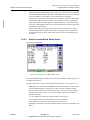
Details of the Exciter Status Screens
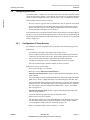
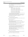
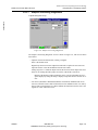
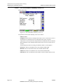
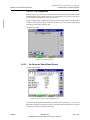
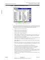
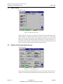
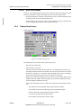
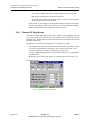
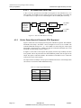
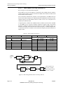
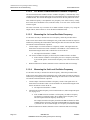
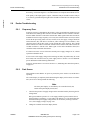
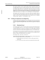
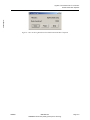
Controller Board Status Screen
ControllerStatus.bmp
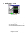
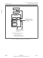
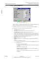
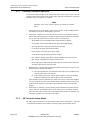
Figure 3-24 Controller Board Status Screen
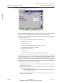
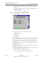
The Controller Board screen is shown in Figure 3-24, with screen entries listed below.
• Temp: This is the ambient air temperature of the digital (bottom) side of the exciter.
• 3.3 Vdc: This is the output of the 3.3 V dc to dc converter.
• 5 Vdc: This is the board input voltage from the main power supply.
• RTC battery: (OK or FAULT) Fault means battery is low and needs replaced.
• MPC823 PLL: (Ok or FAULT) This is the lock status of the internal PLL of the
MPC823 micro controller on the controller board. It indicates the internal 75 MHz
clock is locked to the 32.768 KHz crystal oscillator.
• Board Rev: Board revision for the Controller board.
• CPLD Rev: Revision level of the CPLD in the controller board.
• EEPROM: (Ok or FAULT) This EEPROM is used to save the user entered menu selection from the various LCD screens.
• Boot Rev: Boot code revision level for the controller board.
• APP Rev: Micro controller application code revision level on the controller board.
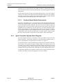
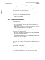
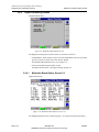
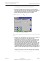
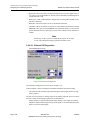
3.4.6.1.1 Controller Board Diagnostics
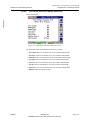
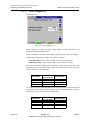
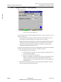
A Bit FIFO Test Pattern function is available on the Controller Board Diagnostics screen.
This function is used by engineering and must remain disabled. If enabled, it will block the
normal signal flow.
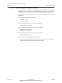
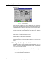
The DSP/FPGA S/W Watchdog is also available on the Controller Board Diagnostics
screen. This function is used by engineering and is normally disabled.
Page: 3-26
888-2604-001
WARNING: Disconnect primary power prior to servicing.
03/08/07