1
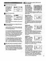
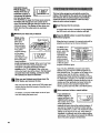
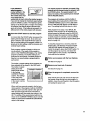
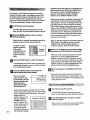
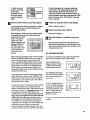
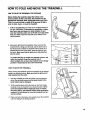
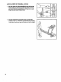
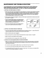
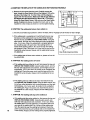
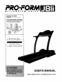
PRO.FORM
MILLENNIUM
DRIVE"
Model No. 831.297990
Serial No.
Find the sedal number in the location
shownbelow. Write the serial number
in the space above for reference.
HELPLINEI
1-800-736-6879
USER'S MANUAL
SEARS, ROEBUCK AND CO., HOFFMAN ESTATES, IL 60179
TABLE OF CONTENTS
IMPORTANT PRECAUTIONS .................................................................
BEFORE YOU BEGIN .......................................................................
ASSEMBLY ...............................................................................
OPERATION AND ADJUSTMENT
.............................................................
HOW TO FOLD AND MOVE THE TREADMILL
..................................................
MAINTENANCE AND TROUBLE-SHOOTING
...................................................
CONDITIONING GUIDELINES ...............................................................
PART LIST ...............................................................................
ORDERING REPLACEMENT PARTS ..................................................
FULL 90-DAY WARRANTY ...........................................................
Note: An EXPLODED DRAWING is attached in the center of this manual.
2
3
5
6
7
15
17
19
22
Back Cover
Back Cover
IMPORTANT PRECAUTIONS
3
The decals shown at the right and
below have been placed on your
treadmill. If one of the decals is missing, or if it Is not legible, please call
our toll-free HELPLINE to order a free
replacement decal (see the back
cover of this manual). Apply the decal
in the location shown.
KEEPHANDSANDFEETAWAY
FROMTHIS AREAWHILETHE
TREADMILLIS IN OPERATION.
4
BEFORE YOU BEGIN
Thank you for selecting the new PROFORIVP J81i
treadmill. The J81i treadmill combines advanced technologywith innovative design to let you enjoy an excellent form of cardiovascularexercise in the convenience
and privacy of your home. And when you're not exercising, the unique J81i can be folded up, requiring less
than half the floor space of other treadmills.
Monday through Saturday, 7 a.m. until 7 p.m. Central
Time (excluding holidays). To help us assist you,
please note the product model number and sedal number before calling. The model number of the treadmill
is 831.297990. The sedal number can be found on a
decal attached to the treadmill (see the front cover of
this manual for the location).
For your benefit, read this manual carefully before
using the treadmill. If you have additional questions,
please call our toll-free HELPLINE at 1-800-736-6879,
Before reading further, please review the drawing
below and familiarize yourself with the parts that are
labeled.
Water BotUe
(Bottle
not included)
Book Holder
Accessory Holder
Hand Weights
Handrail
Storage Latch
Key/Clip
Pulse
Sensor
LEFT SIDE
RIGHT SIDE
Walking Belt
On/Off Switch
Circuit
Breaker
Foot Rails
Front
Wheel
Cushion Adjustment
Power
Cushioned Walking Platform
Rear Roller
Adjustment Bolts
5
ASSEMBLY
Assembly requires two people. Set the treadmill in a cleared area and remove all packing materials. Do not
dispose of the packing materials until assembly is completed. No tools are required for assembly.
1. With the help of a second person, carefully raise the
Uprights (15) until the treadmill is in the position shown.
2.
If the Handrail Grips (91) are not attached, slide a
Handrail Grip onto the square tube on the left Upright
(15). Attach the Handrail Gdp with two Fastenem (63).
Attach the other Handrail Grip (not shown) to the right
Updght. Note: Extra Fasteners may be included.
If the Handrail Grips (91) do not touch the Uprights (15),
squeeze the Handrail Grips and press them towards the
Uprights repeatedly until the Handrail Grips touch the
Uprights.
91
Next, make sure the Lock Knob Sleeve (93) is fully inserted into the left Upright (15). Remove the Lock Knob
(92) from the Lock Pin (97). Make sure that the Lock Pin
Collar (95) and the Spring (94) are on the Lock Pin.
Insert the Lock Pin into the left Upright (15) and tighten
the Lock Knob onto it.
3. Remove the backing from the Adhesive Clip (29). Press
the Adhesive Clip onto the base of one of the Uprights
(15). Press the Allen Wrench (24) into the Adhesive Clip.
3
15
29
4. Make sure that all parts are tightened before you use the treadmill. Place a mat under the treadmill to
protect the floor or carpet.
6
OPERATION AND ADJUSTMENT
THE PERFORMANT LUBE TM WALKING BELT
Your treadmill features a walking belt coated with
PERFORMANT LUBE TM, a high-performance lubricant.
IMPORTANT: Never apply silicone spray or other
substances to the walking belt or the walking plat,
form. Such substances will deteriorate the walking
belt and cause excessive wear.
This product is for use on a nominal 120-volt circuit,
and has a grounding plug that looks like the plug illustrated in drawing t below. A temporary adapter that
looks like the adapter illustrated in drawing 2 may be
used to connect the surge suppressor to a 2-pole
receptacle as shown in drawing 2 if a propedy
grounded outlet is not available.
HOW TO PLUG IN THE POWER CORD
€_-I_Grounded
_'l
_
_G!n!_il
_'1" _1
Your treadmill, like any other type of sophisticated
electronic equipment, can be seriouslydamaged by
sudden voltage changes in your home's power.
Voltage surges, spikes, and noise interference can
result from weather conditions or from other appliances
being turned on or off. To decrease the possibility of
your treadmill being damaged, always use a surge
suppressor with your treadmill (see drawing 1 at
the right).
Surge suppressors are sold at most hardware stores
and department stores. Use only a single-outlet surge
suppressor that is UL 1449 listed as a transient voltage
surge suppressor (TVSS). The surge suppressor must
have a UL suppressed voltage rating of 400 volts or
less and a minimum surge dissipation of 450 joules.
The surge suppressor must be electrically rated for
120 volts AC and 15 amps.
This product must be grounded. If it should malfunction or break down, grounding provides a path of least
resistance for electric current to reduce the risk of electric shock. This product is equipped with a cord having
an equipment-grounding conductor and a grounding
plug. Plug the power cord into a surge suppressor,
and plug the surge suppressor into an appropriate
outlet that is properly installed and grounded in
accordance with all local codes and ordinances.
( "J
Outlet Box
Surge Suppressor
'!',l_'J p_ll
GroundingPin
G rounded Outlet Box
Adapter
^
_k'%_-,_l
Surge _uppressor
Metal Screw
The temporary adapter should be used only until a
properly grounded outlet (drawing 1) can be installed
by a qualified electrician.
The green-colorad rigid ear, lug, or the like extending
from the adapter must be connected to a permanent
ground such as a properly grounded outlet box cover.
Whenever the adapter is used it must be held in place
by a metal screw. Some 2-pole receptacle outlet box
covers are not grounded. Contact a qualified electrician to determine if the outlet box cover is
grounded before using an adapter.
7
CONSOLE DIAGRAM
Program Indicatol
Displays
LED Matrix
and Track
Displays
Program Indicators
oooooooooe
ooooooooeo
ooooo=eeeoo
Note: If there is a sheet of clear plastic
on the face of the console, remove it.
__
Clip
treadmill and six programs control the speed of the
treadmill as they guide you through effective workouts.
You can even create custom workout programs and
save them in the console's memory for future use.
An optional chest pulse sensor adds even more features
to the console. The chest pulse sensor continuously
monitors your heart rate during your workouts and
offers hands-free operation. To purchase an optional
chest pulse sensor, refer to page 14.
STEP-BY-STEP CONSOLE OPERATION
Note: The treadmill console can display speed and
distance in either miles or kilometers (see SPEED/
PACE DISPLAY on page 9). For simplicity, all instructions in this section refer to miles.
FEATURES OF THE CONSOLE
The treadmill console offers an impressive array of
features to help you get the most from your workouts.
When the manual mode is selected, the speed and
inclineof the treadmill can be changed with a touch of a
button. As you exemise, the LED track and four displays
will provide continuous exemise feedback. With the
buiit-in pulse sensor, you can even measure your heart
rate.
In addition, the console offers ten workout programs.
Four programs automatically control the incline of the
8
To operate the console,
first make sure that the
on/off switch, located
near the power cord, is
in the on position.
OnJ
Position
Next, plug in the power cord (see HOW TO PLUG IN
THE POWER CORD on page 7).
Step onto the foot rails of the treadmill. Find the clip
attached to the key (see the drawing above), and slide
the clip onto the waistband of your clothing. Follow the
instructions on pages 9 to 13 to operate the console.
_'.'_ Follow your progress with the LED track and
the four displays.
D
Insert the key Into the console.
A moment after the
key is inserted,the
four displays, the
LED track, and
vadous indicators
will light.
B
tg
Select the manual mode.
When the key is
inserted, the manual
_lndicator
mode will be selected,
as shown by the
manual indicator, if
you have selected a
workout program,
press the mode button repeatedly until the manual
indicator lights.
_!
Press the START button and adjust the speed
of the walking belt.
A moment after the START button is pressed, the
walking belt will begin to move. Hold the handrails
and carefully begin walking.
As you exemise, change the speed of the walking
belt as desired by pressing the SPEED buttons.
Each time one of the buttons is pressed, the speed
will change by 0.1 mph. The buttons can be held
down to change the speed setting quickly. Note: It
may take a few seconds for the walking belt to
reach the selected speed setting.
To stop the walking belt, press the STOP button.
The TIME/INCLINE display will begin to flash. To
restart the walking belt, press the START button
again. To stop the walking belt and reset the displays, hold down the STOP button for two seconds.
B
Adjust the incline of the treadmill as desired
To change the incline of the treadmill, press the
INCLINE buttons.Each time one of the buttons is
pressed, the inclinewill change by 0.5%. The buttons can be held down to change the inclinequickly.
Note: It may take a few seconds for the treadmillto
reach the selected inclinesetting.
The LED Track-In ooooo oooo nd
When the manual
HoooooooosoHff
mode is selected, the
oooooooooe
oooooooooo
LED matrix will display
O0000000SO
a track. The track repO000_OO000
resents a distance of
1/4 mile. As you exercise, the indicators around the track will light one at
a time until you have completed 114 mile. A new lap
willthen begin.
u.oooo
DISTANCE/LAPS
display--This display
shows the distance that
the walking belt has
moved and the number
of 1/4-mile laps you
have completed. The display will altemate between
one number and the other every seven seconds;
the indicator will light when the number of laps is
shown.
TIME/INCLINE
display--This display
shows the elapsed time
and the incline level of
the treadmill. The
display will alternate
between one number and the other every seven
seconds; the indicator will light when the incline is
shown, Note: When a workout program is selected, the display will show the time remaining in
the program.
SPEED/PACE
display--This display
shows the speed of the
walking belt and your
current pace (pace is
measured in minutes
per mile). Every seven seconds, the display will
change from one number to the other;,the indicator
will light when your pace is shown.
Note: The console can
display distance, speed
and pace in either miles
or kilometers. To see
which unitof measurement is selected, hold
down the STOP button while inserting the key into
the console. An =E," for english miles, or an "M," for
metric kilometers, will appear in the CALS/FAT
CALS/PULSE display. If you want to change the
unit of measurement, press the SPEED L_ button.
Remove and then reinsert the key.
9
CALS/FATCALS/
PULSEdisplay This
displayshowstheapproximate
numbersof
calories and fat calories
you have bumed (see
FAT BURNING on page 19). Every seven seconds,
the display will change from one number to the
other;,the indicator will lightwhen the number of fat
calodes is shown. This display will also show your
heart rate when the pulse sensor is used (see
step 6).
r_
Measure your heart rate, if desired.
Stand on the
foot rails and
place your
hands on the
metal contacts
on the handrail.
Your palms
must be resting
on the upper
contacts, and
your fingers must
be touching the
lower contacts--
When you are finished exercising, press the
STOP button and remove the key.
Step onto the foot rails, press the STOP button and
remove the key from the console. Keep the key in
a secure place.
In addition, move the on/off switch to the oft position and unplug the power cord.
10
D
Insert the key into the console.
A moment after the key is inserted,the four displays,
the LED track, and various indicators will light.
B
Press the MODE button to select the desired
workout program.
Metal Contacts
avoid moving your hands. When your heart rate
is detected, the heart-shaped indicator in the
CALS/FAT CALS/PULSE display will flash
steadily and a "P" will appear. After a few seconds, your heart rate will be shown. For the most
accurate heart rate reading, continue to hold
the contacts for about 15 seconds.
B
The four inclineprograms automatically controlthe
incline of the treadmillas they guide you through effective workouts;the six speed programs automatically
control the speed of the treadmill. Follow the steps
below to use a workout program.
When the key is inserted, the manual mode will be
selected, as shown by the manual indicator.
To select one of
the workout pro-
repeatedly until
one
ofbutton
the
four
modegrams,
press
the
incline program
indicators or one
Program Indicators
: ::3--.J_,
:_
,_
:'_r"_"
: _L.L3_
"
"
I_
of the six speed
program indicators lights.
Note: The five AEROBIC programs are twenty
minutes long; the five FAT BURN programs are
thirty minutes long. The graphs on the sides of the
console show how the incline or speed of the
treadmill will change dudng the programs. During
the AEROBIC I programs, for example, the incline
or speed will gradually increase during the first ten
minutes and then gradually decrease during the
last ten minutes. Each program begins with a
warm-up peded and ends with a cool-down period.
l_RSet
s maximum incline or speed setting.
incline program, a
number willflash in the
TIME/INCLINE display.
_B /
This number is the maximum incline that the
treadmill will reach during the selected program. If
you want to change the maximum incline setting,
press the INCLINE A button.The maximum incline
setting can be from 4.5% to 10%. If the setting is
increased, the difficulty level of the entire program
will increase. If the settingis decreased, the difficulty
level of the entire program willdecrease.
If you selected a
speed program, a
number will flash in the
SPEED/PACE display.
This number is the maximum speed that the
walking belt will reach during the selected program.
If you want to change the maximum speed setting,
press the SPEED Z_button. The maximum speed
setting can be from 4 mph to 10 mph. If the setting
is increased, the difficultylevel of the entire program will increase. If the setting is decreased, the
difficultylevel of the entire program willdecrease.
If an incline program is selected, the speed of the
treadmill can be changed during the program with
the SPEED buttons. If a speed program is selected, the incline of the treadmill can be changed
with the INCLINE buttons.
The program will continue until the incline or
speed setting of the last period is shown in the
CURRENT PERIOD column of the LED matrix
and the TIME/INCLINE display counts down to
zero. The walking belt will then slow to a stop.
If the progrem is too easy or too difficult, the
intensity of the program can be adjusted. If an
incline progrem is selected, press the INCLINE
buttons to adjust the maximum incline setting; if
a speed program is selected, press the SPEED
buttons to adjust the maximum speed setting (see
step 3 on page 10).
I_1 Press the START button to start the program
A moment after the START button is pressed, the
walking belt will begin to move. (If an incline program is selected, the treadmill will also adjust to
the first inclinesetting of the program, unless it is
already at the first setting.) Hold the handrails and
carefully begin walking.
Each program consists of twenty or thirty oneminute pedods. (The length of the program is
shown in the TIME/INCLINE display.) If an incline
program is selected, one incline setting is programmed for each period; if a speed program is
selected, one speed setting is programmed for
each period.
To stop the program for a moment, press the
STOP button. The displays will pause and the
TIME/INCLINE display will begin to flash. To
restart the program, press the START button. To
end the program at any time, hold down the
STOP button for two seconds. The MANUAL
mode will then be selected.
I_
Follow your progress with the four displays.
See step 5 on page 9.
The incline or speed settings of the program you
have selected will be shown in the LED matrix.
The incline or speed
setting of the first
CURRENT PERIOD
period will be shown
in the flashing
O0
O00000e
CURRENT PERIOD
O0
oo000ee
column. The settings
O0
ooeeeoo
O0
eooeeee
of the next seven
O0
eezeeSee
pedods will be shown
in the seven columns
to the right.
r_
Measure your heart rate, if desired.
See step 6 on page 10.
HootoooooooH
B
When the program is completed, remove the
key.
H.ooioo.....HI
Step onto the foot rails and remove the key from
the console. Keep the key in a secure place. In
addition, move the on/off switch to the off position
and unplug the power cord.
When only three seconds remain in the first oneminute period of the program, both the CURRENT
PERIOD column and the column to the right will
flash and three tones will sound. All incline or
speed settingswill then move one column to the
left. The setting of the second period will then be
shown in the CURRENT PERIOD column and the
incline or speed of the treadmill willautomatically
adjust to that setting.
11
__/.
*
*
;* ". -.:_Y+i
¸¸ _i_
adjust the speed and inclineof the treadmill to the
desired levels with the SPEED and INCLINE buttons. Every few times the SPEED buttons are
pressed, one additional indicator will light or
darken in the CURRENT PERIOD column.
_-_-_.
_.._
The Custom 1 and Custom 2 programs are workout
programs that you create. The programs control both
the speed and the incline of the treadmill, and can be
up to 40 minutes long. The programs are stored in
memory and can be changed as many times as desired.
Follow the steps below to create a custom program.
D
When the first period is completed, three tones will
sound and the current speed and inclinesettings
will be stored in memory, All settingsshown in the
LED matrixwill then move one column to the left
and the speed settingof the second peded will be
shown in the CURRENT PERIOD column. Program
speed and incline settings for the second period
as described above. Repeat this procadure until
you have programmed speed and incline settings
for as many periods as desired. Programs can
have up to forty periods.
Insert the key into the console.
A moment after the key is inserted,the four displays, the LED track and various indicatorswill light.
B
Press the MODE button to select a custom
workout program.
When the key is inserted, the manual mode will be
selected, as shown by the manual indicator.
To select a custom
program, press the
mode button
repeatedly until one
of the two custom
program indicators
lights.
_
rogram
Note: To stop the progrem for a moment, press the
STOP button. The displays will pause and the
TIME/INCLINE display will begin to flash. To
restart the pmgrem, press the START button.
_When
you are finished programming settings,
hold down the STOP button for two seconds.
Indicator
When you have programmed speed and incline
settings for as many one-minute periods as
desired, hold down the STOP button for two seconds. The speed and inclinesettingsthat you have
programmed and the length of the program will be
stored in memory. To use the programagain, see
HOW TO USE CUSTOM PROGRAMS below.
Press the START button to start the program.
A moment after the START button is pressed, the
walking belt will begin to move. Hold the handrails
and carefully begin walking.
_!
Press the LEARN button and program the
desired speed and incline settings.
r_
when the program is completed, remove the
key.
Step onto the foot railsand remove the key from
the console. Keep the key in a secure place. In addition, move the on/off switch to the off position and
unplug the power cord.
When the LEARN
button is pressed, the
LEARN indictorwill light.
Speed and incline settings can be programmed only when
the indicator is lit.
Each custom program is divided into one-minute
periods. One speed setting and one incline setting
can be programmed for each period. The speed
setting of the first
peded is shown in the
CURRENT PERIOD
flashing CURRENT
PERIOD column of
O0
0000000
the LED matrix. (The
O0
0000000
incline settings are not
O0
0000000
shown in the matrix.)
O0
O00000O
UOOSOOOOOOOUl
To program speed
and incline settings for
the first pedod, simply
D
Insert the key into the console.
A moment after the key is inserted,the four displays, the LED track and various indicatorswill light.
B
Press the MODE button to select a custom
workout program.
nootoooooooH!
When the key is inserted, the manual mode willbe
selected, as shown by the manual indicator.
H-oo oooooooNr
12
To select a custom
program, press the
mode button
repeatedly until one
of the two custom
program indicators
lights.
To stop the program for a moment, press the
STOP button.The displays will pause and the
TIME/INCLINE display will begin to flash. To
restart the program, press the START button. To
end the program at any time, hold down the STOP
button for two seconds. The MANUAL mode will
then be selected.
mw
_
rogram
Indicator
!_1 Press the START button to start the program.
A moment after the button is pressed, the walking
belt will begin to move. Hold the handrails and
carefully begin walking.
Each program is divided into one-minute pedods.
One speed setting and one incline setting are
programmed for each
period. The speed
CURRENT PERIOD
setting of the first
period is shown in the
00_00'00000
flashing CURRENT
O0
O0000eo
PERIOD column of
O0
oooeeee
O0
oeeee@e
the LED matrix. (The
oo
ee:eeeoo
incline settings are
not shown in the
matrix.)
L_
Follow your progress with the LED displays.
Refer to step 6 on page 11.
[]Measure
your heart rate, if desired.
See step 6 on page 10.
r_When
key.
the program Is completed, remove the
!Nee
ooooo.oflF
Step onto the foot rails and remove the key from
the console. Keep the key in a secure place. In addition, move the on/oft switch to the off positionand
unplug the power cord.
U°°l°°°°°.-Ui
THE INFORMATION MODE
When onlythree seconds remain in the first period,
both the CURRENT PERIOD column and the column to the right will flash and three tones will
sound. All speed settings will then move one column to the left. The speed setting of the second
pedod will then be shown in the CURRENT PERIOD column and the speed and incline of the
treadmill will adjust to the second settings that you
programmed previously.
To access the informationmode, hold down the STOP
button while inserting the key into the console.
The program will continue until the speed setting
of the last period is shown in the CURRENT PERIOD column of the LED matrix and the TIME/INCLINE display counts down to zero. The walking
belt will then slow to a stop.
will show the total number of
hourS that the treadmill has
been used.
During the program, the speed and inclinesettings
of the current period can be adjusted with the
SPEED and INCLINE buttons. Adjustments will not
be stored in memory. To reprogram speed and incline settings, press the LEARN button. The
LEARN indicator will light. Speed and incline settings can be reprogrammed only when the indicater is lit. Next, adjust the speed and incline of
the treadmill with the SPEED and INCLINE buttons. When the current period of the program is
cornpleted, the new speed and incline settings will
be stored in memory. When you have reprogrammed speed and incline settings for as many
periods as desired, press the LEARN button again.
The DISTANCE/LAPS
display will show the total
number of miles that the
walking belt has moved.
TheTM NOL
,U1
_,=, --
An "E," for english miles, or
an "M," for metric kilometers,
will appear in the CALS/FAT
CALS/PULSE display. If you
want to change the unit of
measurement, press the
SPEED ,5 button.
To exit the informationmode, remove the key from the
console.
13
HOW TO ADJUST THE FIRMNESS OF THE
WALKING PLATFORM
The walldng
platform is
specially designed
to cushion the
impact as you
walk or run on
the treadmill. The
firmness of the
-Lift Hero
walking platform
can be adjusted
Control
to any of three
settings using the
controlon the right side of the treadmill. For a firmer
walking platform,turn the control clockwise. For a
softer walking platform,turn the control counterclockwise. If it is difficult to turn the control, lift up on
the walking platform while turning the control.
Note: The faster you run on the treadmill, the firmer the
walking platform should be. if the walking platform is
too soft, the treadmill may bounce excessively.
HOW TO USE THE HAND WEIGHTS
The included hand
weights let you add
upper body exercise
to your workouts.As
you walk on the troadmill, hold the 2-pound
weights at your sides
or press the weights
above your head. To
increase the intensity
of your exercise, use
the 3-pound weights.
WARNING: Do not
use the hand
weights at speeds
higher than a walk.
Using weights and not holding the handrails may
compromise your ability to maintain your balance.
Exercises using weights should be attempted only
by experienced users.
14
The hand weights
can be stored in the
handy weight rack
on the console.
Weight Rack
THE OPTIONAL CHEST PULSE SENSOR
An optional chest pulse sensor adds even more
features to the console. The chest pulse sensor offers
hands-free operation and continuouslymonitors your
heart rate during your workouts.To purchase the
optional chest pulse sensor, please see the back
cover of this manual.
HOW TO FOLD AND MOVE THE TREADMILL
HOW TO FOLD THE TREADMILL FOR STORAGE
Before folding the treadmill, adjust the Incline to the
lowest position. If this is not done, the treadmill may be
permanently damaged. Next, unplug the power cord. CAUTION: You must be able to safely lift 45 pounds (20 kg) in
•order to raise, lower, or move the treadmill.
p
1. Hold the treadmill with your hands in the locationsshown at
the right. CAUTION: To decrease the possibility of injury,
bend your legs and keep your back straight. As you
raise the treadmill, make sure to lift with your legs rather
than your back. Raise the treadmill about halfway to the
vertical position.
2. Move your right hand to the position shown and hold the
treadmill firmly. Using your left hand, pull the latch knob to
the left and hold it. Raise the treadmill until the latch pin is
aligned with the hole in the catch. Insert the latch pin into
the catch. Make sure that the latch pin is fully inserted
into the catch.
To protect the floor or carpet from damage, place a mat
under the treadmill. Keep the treadmill out of
direct sunlight. Do not leave the treadmill in the storage
Open
Knob_
Pin----Latch
Closed
position in temperatures above 85 ° Fahrenheit.
HOW TO MOVE THE TREADMILL
Before moving the treadmill, convert the treadmill to the storage
position as described above. Make sure that the latch pin is
fully inserted into the catch.
1. Hold the handrails as shown and place one foot against a
wheel. Do not hold or push on the book holder or the
book holder may be damaged.
2. Tiltthe treadmill back until it rolls freely on the front wheels.
Carefully move the treadmill to the desired location, Never
move the treadmill without tipping it back. To reduce
the risk of injury, use extreme caution while moving the
treadmill, Do not attempt to move the treadmill over an
uneven surface.
3. Place one foot on the base, and carefully lower the treadmill
until it is resting in the storage position.
15
HOW TO LOWER THE TREADMILL
FOR USE
1. Hold the upper end of the treadmill with your right hand as
shown. Using your left hand, pull the latch knob to the left
and hold it. Pivot the treadmill down until the frame is past
the pin. Slowly release the latch knob.
2. Hold the treadmill firmly with both hands, and lower the
treadmill to the floor. CAUTION: To decrease the possibility of injury, bend your legs and keep your back straight.
6
Open
°ttl
MAINTENANCE AND TROUBLE-SHOOTING
"
Jlost treadmill problems can be solved by following the simple steps below. Find the symptom that
applies, and follow the steps listed, ff further assistance is needed, call our toll-free HELPUNE at
1-800-736-6879, Monday through Saturday, 7 a.m. until 7 p.m. Central Time (excluding holidays).
1. SYMPTOM: THE POWER DOES NOT TURN ON
a. Make sure that the power cord is plugged into a surge suppressor, and that the surge suppressor is plugged
into a prepedy grounded outlet (see page 7). Use only a single-outlet surge suppressor that is UL 1449
listed as a transient voltage surge suppressor (TVSS). The surge suppressor must have a UL suppressed
voltage rating of 400 volts or less and a minimum surge dissipation of 450 joules. The surge suppressor
must be electricallyrated for 120 volts AC and 15 amps.
b. After the power cord has been plugged in, make sure that the key is inserted into the console as far as it will
go. See step 1 on page 9.
c. Check the circuit breaker located on the treadmill near the
power cord. If the switch protrudes as shown, the circuit
breaker has tripped. To reset the circuit breaker, wait for five
minutes and then press the switch back in.
d. Check the on/off switch located on the treadmill near the
power cord. The switch must be in the on position.
c
Tdpped
0
On
Position
j
2. SYMPTOM: THE POWER TURNS OFF DURING USE
a. Check the circuit breaker located on the treadmill frame near the power cord (see 1. c. above). If the circuit
breaker has tripped, wait for five minutes and then press the switch back in.
b. Make sure that the power cord is plugged in.
c. Remove the key from the console. Reinsert the key fully into the console. See step 1 on page 9.
d. Make sure that the on/off switch is in the on position.
e. If the treadmill still will not run, please call our toll-free HELPLINE.
3. SYMPTOM: THE PULSE SENSOR DOES NOT FUNCTION PROPERLY
a. Make sure to stand on the foot rails and avoid moving your hands while measuring your heart rate.
Excessive movement may interfere with hear[ rate readings. If the pulse sensor is not used correctly,your
heart rate will not be shown.
b. Do not hold the metal contacts too tightly; doing so may interfere with heart rate readings.
c. For the most accurate heart rate reading, hold the contacts for about 15 seconds.
d. For optimal performance of the pulse sensor, keep the contacts clean. The contacts can be cleaned with a
soft cloth--never use alcohol, abrasives, or chemicals.
17
4. SYMPTOM: THE DISPLAYS OF THE CONSOLE DO NOT FUNCTION PROPERLY
a. Remove the six screws from the hood. Carefully remove the
hood. Locate the Reed Switch (26) and the Magnet (107) on the
left side of the Pulley (12). Turn the Pulley until the Magnet is
aligned with the Reed Switch. Make sure that the gap between
the Magnet and the Reed Switch is about 1/8". If necessary,
loosen the Reed Switch Screw (109) and move the Reed Switch
slightly.,Retighten the Screw. Re-attach the hood, and run the
treadmill for a few minutes to check for a correct speed reading.
I
I
It
wl
L_J
"
5. SYMPTOM: The walking belt slows when walked on
a. Use only a UL-listed surge protector, rated at 15 amps, with a 14-gauge cord of five feet or less in length.
b. If the walking belt is overtightened, treadmill performance may
decrease and the walking belt may be permanently damaged.
Remove the key and UNPLUG THE POWER CORD. Using the
allen wrench, turn both rear rolleradjustment bolts counterclockwise, 1/4 of atum. When the walking belt is propedy tightened,
you should be able to lift each side of the walking belt 3 to 4
inches off the walking platform. Be careful to keep the walking
belt centered, Plug in the power cord, insert the key and run the
treadmill for e few minutes. Repeat untilthe walking belt is prupedy tightened.
b
Rear Roller Adjustment Bolts
c. If the walking belt still slows when walked on, please call our tollfree HELPLINE.
6. SYMPTOM: The walking belt is off-center
a. If the walking belt has shifted to the left, first remove the key and
UNPLUG THE POWER CORD. Using the allen wrench, turn the
left rear roller adjustment bolt clockwise, and the dght bolt counterolockwise, 1/4 of a turn each. Be careful not to overtighten the
walking belt. Plug in the power cord, insert the key and run the
treadmill for a few minutes. Repeat until the walking belt is centered.
b.
If the walking belt has shifted to the right, first remove the key
and UNPLUG THE POWER CORD. Using the allen wrench, turn
the left rear roller adjustment bolt counterclockwise, and the right
bolt clockwise, 1/4 of a turn each. Be careful not to overtighten
the walking belt. Plug in the power cord, insert the key and run
the treadmill for a few minutes. Repeat until the walking belt is
centered.
a
b
7. SYMPTOM: The walking belt slips when walked on
18
a. If the walking belt slips when walked on, first remove the key and
UNPLUG THE POWER CORD. Using the allen wrench, turn
both rear roller adjustment bolts clockwise, 1/4 of a turn. When
the walking belt is correctly tightened, you should be able to lift
each side of the walking belt 3 to 4 inches off the walking platform. Be careful to keep the walking belt centered. Plug in the
power cord, insert the key and carefully walk on the treadmill for
a few minutes. Repeat until the walking belt is properly tightened.
a
CONDITIONING
GUIDELINES
uses easily accessible carbohydrate calories for energy. Only after the firstfew minutesdoes your body
begin to use storedfat ca/odesfor energy, ff your goal is
to bum fat, adjustthe speed and inclineof the treadmill
untilyour heart rate is near the lowest number in your
training zone. It may also be helpfulto use one of the
console'sFAT BURN programs(see pages 10 and 11).
For maximum fat buming, adjustthe speed and incline
of the treadmill until your heart rate is near the middle
number in your training zone.
Aerobic Exercise
The following guidelines will help you to plan your exercise program. Remember--these are general guidelines only. For more detailed exercise information, obtain a reputable book or consult your physician.
EXERCISEINTENSITY
Whether your goal is to bum fat or to strengthen your
cardiovascular system, the key to achieving the
desired results is to exercise with the proper intensity.
The proper intensity level can be found by using your
heart rate as a guide. The chart below shows recommended heart rates for fat buming and aerobic exercise,
20
30
WORKOUT GUIDELINES
Each workout should include the following three parts:
A Warm-up---Start each workoutwith 5 to 10 minutes
of stretching and light exercise. A proper warm-up increases your body temperature, heart rate and circulation in preparation for exercise.
HEART RATE TRAINING ZONES
Age
If your goal is to strengthen your cardiovascular system, your exercise must be "aerobic." Aerobic exercise
is activity that requires large amounts of oxygen for
prolonged pedods of time. This increases the demand
on the heart to pump bloodto the muscles, and on the
lungs to oxygenate the blood. For aerobic exercise,
adjust the speed and inclineof the treadmill until your
heart rate is near the highest number in your training
zone. It may also be helpfulto use one of the console's
AEROBIC programs (see pages 10 and 11).
40
50
60
70
80
To find the proper heart rate for you, first find your age
near the bottom of the chart (ages are rounded off to
the nearest ten years). Next, find the three numbers
above your age. The three numbers define your "training zone." The lower two numbers are recommended
heart rates for fat burning; the higher number is the
recommended heart rate for aerobic exercise.
To measure your heart rate during exercise, use the
pulse sensor on the console, if your heart rate is too
high or too low, adjust the speed and incline of the
treadmill.
Fat Burning
To burn fat effectively, you must exercise at a relatively
low intensity level for a sustained period of time,
During the first few minutes of exercise, your body
Training Zone Exercis_After warming up, increase
the intensityof your exemise until your pulse is in your
training zone for 20 to 60 minutes. (During the first few
weeks of your exercise program, do not keep your
pulse in your training zone for longer than 20 minutes.)
Breathe regularly and deeply as you exercise--never
hold your breath.
A Cool-down---Finish each workout with 5 to 10 minutes of stretchingto cool down. This will increase the
flexibility of your muscles and will help prevent post-exercise problems.
Exercise Frequency
To maintain or improve your condition,complete three
workouts each week, with at least one day of rest between workouts. After a few months, you may complete up to five workouts each week if desired. The key
to success is to make exercise a regularand enjoyable
part of your everyday life.
19
SUGGESTED STRETCHES
The correct form for several basic stretches is shown at the right. Move slowly as you stretch--never bounce.
1. Toe Touch Stretch
Stand with your knees bent slightlyand slowly bend forward
from your hips. Allow your back and shoulders to relax as you
roach down toward your toes as far as possible. Hold for 15
counts, then'relax. Repeat 3 times. Stretches: Hamstrings,
back of knees and back.
2. Hamstring Stretch
Sit with one leg extended. Bringthe sole of the opposite foot
toward you and rest it against the inner thigh of your extended
leg. Reach toward your toes as far as possible. Hold for 15
counts, then relax. Repeat 3 times for each leg. Stretches:
Hamstrings,lower back and groin.
3. Calf/Achilles Stretch
With one leg in front of the other, reach forward and place your
hands against a wall. Keep your back leg straight and your
back foot flat on the floor. Bend your front leg, lean forward and
move your hips toward the wall. Hold for 15 counts, then relax.
Repeat 3 times for each leg. To cause further stretching of the
achilles tendons, bend your back leg as well. Stretches:
Calves, achilles tendons and ankles.
4
4. Quadrlceps Stretch
With one hand against a wall for balance, roach back and
grasp one foot with your other hand. Bring your heel as close
to your buttocksas possible. Hold for 15 counts, then relax.
Repeat 3 times for each leg. Stretches: Quaddceps and hip
muscles.
5. Inner Thigh Stretch
Sit with the soles of your feet together and your knees outward.
Pull your feet toward your groinarea as far as possible. Hold
for 15 counts, then relax. Repeat 3 times. Stretches:
Quaddceps and hip muscles.
2O
NOTES
21
PART LISTmModel No. 831.297990
RllgBA
To identifyparts listed below, refer to the EXPLODED DRAWING attached in the center of this manual.
Key
No. Qty.
1
2
3
4
5
6
7
8
9
10
11
12
13
14
15
16
17
18
19
20
21
22
23
24
25
26
27
28
29
30
31
32
33
34
35
36
37
38
39
40
41
42
43
44
45*
46
47
48
49
50
22
2
2
1
1
4
6
6
1
2
2
1
1
28
1
1
1
2
3
4
1
8
1
2
1
1
1
1
1
1
2
2
1
1
1
1
3
1
1
1
1
1
1
2
3
1
1
1
1
1
1
Description
,Center Track
Foot Rail
Left Foot Rail Cap
Front Roller Adjustment Nut
Isolator
Bumper
Platform Screw
Walking Platform
Frame Pivot Bolt
Frame Pivot Spacer
Walking Belt
Front Roller/Pulley
Small Screw
Motor Belt
Base
Incline Frame
Hood Bracket (long)
Bracket Clip
Small Screw
Console Plate
Nut
Lift Motor Shield
Incline Motor Bolt
Allen Wrench
Incline Motor
Reed Switch
Upright Plug
Updght Ground Screw
Adhesive Clip
Wheel Bolt
Front Wheel
Hood Bracket (short)
Motor Pivot Nut
Pulley/Flywheel/Fan
Motor
Motor Tension Bolt
Motor Tension Washer
Star Washer
Motor Tension Nut
Motor Pivot Bolt
Motor Hoed
Incline Motor Shield
Incline Pivot Washer
Adj. Washer
Motor/Pulley/Fly./Fan
Front Roller Adj. Bolt
Choke
Electronics Bracket
Controller
ElectronicsShield
Key
No. Qty.
Description
51
1
52
4
53
1
54
1
55
1
56
1
57
1
58
1
59
2
60
1
61
1
62
1
63
26
64
1
65
2
66
1
67
2
68
1
69
1
70
4
71
1
72
2
73
1
74
2
75
7
76
2
77
2
78
1
79
1
80
2
81
1
82
1
83
1
84** 1
85
1
86
2
87
2
88
2
89
5
90
1
91
2
92
1
93
1
94
1
95
1
96
1
97
1
98
1
99
4
100
1
Power Supply
Plastic Stand-off
Power Cord
Grommet
On/Off Switch
Circuit Breaker
Outlet Bracket
Book Rack
Belt Guide
Shock
Front Belly Pan
Right Feet Rail Cap
Belly Pan Fastener
Console Base
Frame Guide Screw
Frame Guide
Rear Isolator
Belly Pan
Warning Decal
Hood Screw
Key/Clip
Rear Endcap Bracket
Rear Endcap
Rear Endcap Pad
Endcap Screw/Ground Screw
Rear Roller Adj. Bolt
Caution Decal
Latch Decal
Frame
Rear Deck Screw
Console
Latch Catch
Rear Roller
Optional Chest Pulse
Cable Tie
Cable Tie Screw
Cable Tie Clamp
8" Cable Tie
4" Cable Tie
Upright Wire Harness
Handrail Grip
Lock Knob
Lock Knob Sleeve
Spdng
Lock Pin Collar
Pin Clip
Lock Pin
8" Wire Harness
Pulse Sensor Plate
Ground Wire
Key
No.
Qty.
',01" 1
102 32
103
2
104
2
105
4
106
1
107
1
108
1
109
1
110
1
f 11
2
112
2
113
2
114
2
115
2
116
2
117
2
118
1
119
1
120
1
Description
Pulse Bar
Screw
Pulse Bar Washer
Pulse Bar Bolt
Updght Endcap
Upright Grommet
Magnet
Incline Reed Switch
Reed Switch Screw
Reed Switch Clip
Endcap Spacer
2-1bWeight
3-1bWeight
Cushion Plate
Adjustable Deck Cushion
Rod Nut
Rod Bolt
Cushion Rod
Incline Motor Spacer
Incline Optic Disk
Key
No. Qty.
Description
121
122
123
124
#
#
#
#
#
#
#
#
#
#
Optic Switch Nut
Optic Switch Washer
Optic Switch Bolt
Optic Switch
14" White Wire, 2 F
8" White Wire, M/F
4" White Wire, M/F
4" Black Wire, 2 F
4" Black Wire, M/Ring
9" Black Wire, M/F
8" Blue Wire, 2 F
8" Red Wire, M/F
8" Green Wire, F/Ring
User's Manual
1
1
1
1
1
1
1
1
1
1
1
1
1
1
# These parts are not illustrated
* Includes all parts shown in the box
** For more informationabout the optional pulse kit,
see page 14.
Specifications are subject to change without notice. For information about ordering replacement parts, see the
back cover of this manual.
23
EXPLODED DRAWING--Model
No. 831.297990
R1198A
105
,_
102
/
/
71
112
_84"*
113
93
92
9',
97
i
101"
7O
96
63
86UIi;
7O
41
87
7O
21
7O
3O
"'"
105
_
5
29
24
EXPLODED
DRAWINGBModel
No. 831.297990
R1198A
51
114
18--_p
115
_116
117
118
13
3_.
102
1
56
J
26
9
5O
115
!1
117
114
21
2
82
S_
<,_--107
""'-_
11
/
102
5
_,_18
35-
12
80
21"
/45"
36
21
39 .J
l
102
61
80
111
62
_ 63_.
76
J
.J
44
69
111
68
76
75
19
44
73
_75
'_100
REMOVE THIS EXPLODED DRAWING FROM THE
USER'S MANUAL. SAVE THIS EXPLODED DRAWING
FOR FUTURE REFERENCE.
To identify the parts shown on this exploded drawing, refer to the PART LIST on pages 22 and 23 of
the USER'S MANUAL,
13
SEARS
The model number and sedal number of your PROFORIVP J8U
treadmill are listed on a decal attached to the frame. See the front
cover of this manual to find the locationof the decal.
Model No. 831.297990
QUESTIONS?
All replacement parts are available for immediate purchase or
special order when you visit your nearest SEARS Service Center.
To request service or to order parts by telephone, call the toll-free
numbers listed at the left.
If you find that:
• you need help assembling or
operating the PROFORM J81i
treadmill
• a part is missing
When requesting help or service, or ordering pads, please be
prepared to provide the following information:
• The NAME OF THE PRODUCT (PROFORIVP J81itreadmill)
• or you need to schedule repair
service
call our toll-free HELPLINE
• The MODEL NUMBER OF THE PRODUCT (831.297990)
• The KEY NUMBER AND DESCRIPTION OF THE PART (see the
EXPLODED DRAWING and PART LIST included in this manual)
1-800-736-6879
Monday-Saturday, 7 am-7 pm
Central Time (excluding holidays)
REPLACEMENT
PARTS
If parts become worn and need
to be replaced, call the following
ton-free number
1-800-FON-PART
(1-800-366-7278)
FULL 90 DAY WARRANTY
For 90 days from the date of purchase, if failure occurs due to defect in material or workmanship in this
SEARS TREADMILL ExERcISER, contact the nearest SEARS Service Center throughoutthe United
States and SEARS will repair or replace the TREADMILL EXERCISER, free of charge.
This warranty does not apply when the TREADMILL EXERCISER is used commercially or for rental purposes.
This warranty gives you specific legal rights, and you may also have other rightswhich vary from state
to state.
SEARS, ROEBUCK AND CO., DEPT. 817WA, HOFFMAN ESTATES, IL 60179
Part No. 149526 H03862-C R1198A
Printed in U,':;A_ 1998 ICON Health & Fitness, Inc.