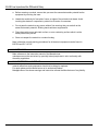
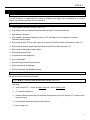
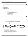
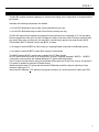
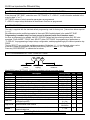
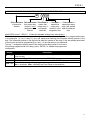
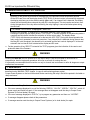
1
Protective Relays SALES AID M-LIB3 Low Impedance Bus Differential Relay S150-34-1 MODULAR LOW IMPEDANCE BUS PROTECTION TYPE M-LIB3 OPERATION MANUAL October 1999 1999 Cooper Industries, Inc. •New Issue. 1 M-LIB3 Low Impedance Bus Differential Relay INDEX 1 General utilization and commissioning directions_______________________________________________________ 3 1.1 Storage and transportation______________________________________________________________________ 3 1.2 Installation___________________________________________________________________________________ 3 1.3 Electrical connection___________________________________________________________________________ 3 1.4 Measuring inputs and power supply_______________________________________________________________ 3 1.5 Outputs loading_______________________________________________________________________________ 3 1.6 Protection earthing_____________________________________________________________________________ 3 1.7 Setting and calibration__________________________________________________________________________ 3 1.8 Safety protection______________________________________________________________________________ 3 1.9 Handling____________________________________________________________________________________ 3 1.10 Maintenance_________________________________________________________________________________ 4 1.11 Fault detection and repair_______________________________________________________________________ 4 2 General characteristics and operation________________________________________________________________ 5 2.1 Modular Low Impedance Bus Bar Protection M-LIB3__________________________________________________ 5 2.2 Main features_________________________________________________________________________________ 5 2.3 Component Modules___________________________________________________________________________ 5 2.3.1 M-BF3 = Income/Feeder Breaker input module (SCE1577)________________________________________ 5 2.3.2 M-BC3 = Bus coupler / sectionalizer module (SCE1578)__________________________________________ 6 2.3.3 M-LID3 =Numerical biased protection relay____________________________________________________ 6 2.4 F/C Rack Panel_______________________________________________________________________________ 7 2.5 Accessoeries_________________________________________________________________________________ 8 2.5.1 CF1- Cable with female plug________________________________________________________________ 8 2.5.2 CFM – Interconnection cable with Male an Female plugs__________________________________________ 9 2.6 Technical Data________________________________________________________________________________ 10 2.7 Current Transformer Requirements________________________________________________________________ 10 3 Apparatus Configuration____________________________________________________________________________ 11 3.1 Single-Line Diagram____________________________________________________________________________ 12 3.2 Application example____________________________________________________________________________ 13 4 Feeder Input Module M-BF3__________________________________________________________________________ 15 4.1 Wiring diagram M-BF3__________________________________________________________________________ 17 5 Feeder Input Module M-BC3__________________________________________________________________________ 18 5.1 Wiring diagram M-BC3__________________________________________________________________________ 20 6 Digital Low Impedance Differential Protection Relay M-LID3_______________________________________________ 21 6.1 General Characteristic__________________________________________________________________________ 22 6.2 Power Supply_________________________________________________________________________________ 22 6.3 Measurements Acquisition and Operation Principle____________________________________________________22 6.4 Operation of the Biased Differential elements________________________________________________________ 23 6.5 Control and Measurements______________________________________________________________________ 25 6.6 Measurements Acquisition and Operation Principle___________________________________________________ 26 6.7 Output relays_________________________________________________________________________________ 27 6.8 Serial Communication__________________________________________________________________________ 27 6.9 Oscillography Records__________________________________________________________________________ 27 6.10 Digital Input__________________________________________________________________________________ 27 6.11 Test________________________________________________________________________________________ 28 6.12 Keyboard and Display Operation__________________________________________________________________ 28 6.13 Reading of Measurements and Recorded Parameters_________________________________________________ 29 6.13.1 Actual Measurements (ACT. MEAS)__________________________________________________________ 29 6.13.2 Max Value (MAX.VAL)_____________________________________________________________________ 29 6.13.3 Last Trip (LASTTRIP)______________________________________________________________________ 29 6.13.4 Trip Number (TRIP NUM)___________________________________________________________________ 29 6.14 Reading of Programmed Setting and Relay’s Configuration_____________________________________________ 30 6.15 Programming_________________________________________________________________________________ 30 6.15.1 Programming of functions settings____________________________________________________________ 30 6.15.2 Programming the configuration of output relays__________________________________________________ 31 6.16 Manual and Automatic Test Operation______________________________________________________________ 32 6.16.1 Mode “TESTPROG ” subprogram “W/O TRIP ”__________________________________________________ 32 6.16.2 Mode “TESTPROG ” subprogram “WithTRIP ”___________________________________________________ 32 6.17 Maintenence__________________________________________________________________________________ 32 6.18 Clock and Calendar____________________________________________________________________________ 33 6.18.1 Clock synchronization______________________________________________________________________ 33 6.18.2 Date and time setting______________________________________________________________________ 33 6.18.3 Time resolution___________________________________________________________________________ 33 6.18.4 Operation during power off__________________________________________________________________ 33 6.18.5 Time tolerance___________________________________________________________________________ 33 6.19 Wiring Diagram M-LID3_________________________________________________________________________ 34 6.20 Electrical Characteristics________________________________________________________________________ 35 2 S150-34-1 GENERAL UTILIZATION AND COMMISSIONING DIRECTIONS Always make reference to the specific description of the product and to the Manufacturer's instructions. Carefully observe the following warnings. 1.1 STORAGE AND TRANSPORTATION Must comply with the environmental conditions stated on the product's instruction or by the applicable IEC standards. 1.2 INSTALLATION, Must be properly made and in compliance with the operational ambient conditions stated by the Manufacturer. 1.3 ELECTRICAL CONNECTION, Must be made strictly according to the wiring diagram supplied with the Product, to its electrical characteristics and in compliance with the applicable standards particularly with reference to human safety. 1.4 MEASURING INPUTS AND POWER SUPPLY, Carefully check that the value of input quantities and power supply voltage are proper and within the permissible variation limits. 1.5 OUTPUTS LOADING, Must be compatible with their declared performance. 1.6 PROTECTION EARTHING When grounding is required, carefully check its efficiency. 1.7 SETTING AND CALIBRATION Carefully check the proper setting of the different functions according to the configuration of the protected system, the safety regulations and the co-ordination with other equipment. 1.8 SAFETY PROTECTION Carefully check that all safety means are correctly mounted, apply proper seals where required and periodically check their integrity. 1.9 HANDLING The electronic components and semiconductor devices mounted on the modules can be seriously damaged by electrostatic voltage discharge which can be experienced when handling the modules. The damage caused by electrostatic discharge may not be immediately apparent but the design reliability and the long life of the product will have been reduced. The electronic are completely safe from electrostatic discharge (8 KV IEC 255.22.2) when housed in their case; withdrawing the modules without proper cautions expose them to the risk of damage. 3 M-LIB3 Low Impedance Bus Differential Relay a. Before removing a module, ensure that you are at the same electrostatic potential as the equipment by touching the case. b. Handle the module by its front-plate, frame, or edges of the printed circuit board. Avoid touching the electronic components, printed circuit tracks or connectors. c. Do not pass the module to any person without first ensuring that you are both at the same electrostatic potential. Shaking hands achieves equipotential. d. Place the module on an anti-static surface, or on a conducting surface which is at the same potential as yourself. e. Store or transport the module in a conductive bag. More information on safe working procedures for all electronic equipment can be found in BS5783 and IEC 147-OF. 1.10 MAINTENANCE Make reference to the instruction manual of the Manufacturer ; maintenance must be carried-out by specially trained people and in strict conformity with the safety regulations. 1.11 FAULT DETECTION AND REPAIR Internal calibrations and components should not be altered or replaced. For repair please ask the Manufacturer or its authorized Dealers. Misapplication of the above warnings and instruction relieves the Manufacturer of any liability. 4 S150-34-1 GENERAL CHARACTERISTICS AND OPERATION 1.12 Modular Low Impedance Bus Bar Protection M-LIB3 The M-LIB system is constituted of a number of modular units, which can be combined to suit to any busbar configuration and allow for easy extension. 1.13 Main features q Low impedance and low burden on main CTS. q High stability with zone biased differential elements and CT saturation detectors. q High speed of operation. q High reliability: duplicated measuring circuits, CTs’secondary circuits supervision, wide and consistent setting ranges q Self-contained input CTs for main zone and for check zone feature without duplication of main CTs. q Self-contained isolator repeat relays switching at secondary of the zone input CTs. q Self-contained discrepancy alarm relays q Multivoltage power supply. q Comprehensive self-diagnostic. q User friendly MMI. q Real time and recorded measurements. q Event records and oscillography q RS 485 serial port with ModBus protocol. 1.14 Component Modules The system includes three basic modules: 1.14.1 M-BF3 = Income/Feeder Breaker input module (SCE1577) Including : q sets of three CTs. 1 set for the Main Zone and 1 for the Check Zone. q CT saturation detectors. q bistable isolator repeat relays for switching the secondary circuits of the input CTs and the zone trip input signal. q Time delayed isolator discrepancy alarm feature q Power supply unit 5 M-LIB3 Low Impedance Bus Differential Relay 1.14.2 M-BC3 = Bus coupler / sectionalizer module (SCE1578) Including : q sets of three auxiliary CTs : 1 set for each side of the bus coupler. q 1 Bus coupler trip output. q 1 Bus Coupler trip input from Feeders’Breaker Failure Relays 1.14.3 M-LID3 = Numerical biased protection relay With the following features : 6 q Double circuit for Biased differential protection. q Double circuit for unbiased differential protection. q Double circuit for CT circuits supervision. q Output relays for phase trip q 1 Supervision alarm relay q 1 Internal fault alarm relay q 1 Lock-out digital input q 1 Remote trigger input q Synchronization digital input q RS 485 communication Port q Timed supervision alarm q Timed discrepancy alarm S150-34-1 2.4 F/C Rack Panel 19”3U rack panel suitable to house up to seven plug-in modules type M-BF3 or M-BC3 including back printed circuit board with : q Diodes for supply of the measurement bus of two Main Zones and one Check Zone q 7 Female sockets for plug-in connection of the M-BF3 or M-BC3 modules. q 7 Terminal boards with screw terminals for connection to the system. q 1 Male connector socket for interfacing with the differential protection relays. q 1 Female connector socket for interconnection with other F/C Rack Panels. q 1 Power supply module: The auxiliary power is supplied by a built-in interchangeable module fully isolated and self protected. Two options are available : 24V(-20%) / 110V(+15%) a.c. a) - 24V(-20%) / 125V(+20%) d.c. 80V(-20%) / 220V(+15%) a.c. b) - 90V(-20%) / 250V(+20%) d.c. Before energizing the unit check that supply voltage is within the allowed limits. Power consumption : nx 4W (n = number of modules M-BF3) The unit can supply up to 12 modules M-BF3 plus two modules M-BC3 (one unit can supply two F/C Rack Panels). 7 M-LIB3 Low Impedance Bus Differential Relay 2.5 ACCESSORIES 2.5.1 CF1 – Cable with female plug Female connector plug with multicore cable for connection between the terminals of the protection relays and the Zone wiring bus. 8 S150-34-1 2.5.2 CFM – Interconnection cable with Male and Female plugs Multicore cable terminated with one male and one female connector plugs for interconnection between F/C Rack Panels. 9 M-LIB3 Low Impedance Bus Differential Relay 2.6 Technical Data q Standards: IEC 255, 1000, CE q Rated Frequency: 50/60 Hz q Rated input current: 1 A q Current overload: 2 In q Transient overload: 100 In q Setting ranges: • Fn = 50/60 Hz • Ids = zone differential current = (0,2-2) In • R = Bias per Unit = (0,4 - 1) p.u. • ISV = Circuit supervision current = (0,1 – 1) In • Operating time: ≤ 20 ms • Stability level: ≥ 40 In max. 2.7 CURRENT TRANSFORMER REQUIREMENTS Current transformer requirements Minimum knee point voltage: VK ≥ F . In . RT where F = Accuracy limit factor (20 recommended) In = Main CT’s rated secondary current RT = Total CT’s secondary loop resistance (see equivalent diagram) VK − RCT In 2 F ⋅In Minimum power: S ≥ RCT = Secondary resistance of main CT RW = Resistance of connection lead RP = Primary resistance of auxiliary ratio matching CT n = IP/IS = Current ratio of auxiliary CT RS = Secondary resistance of auxiliary ratio matching CT Rd = Ohmic burden of M-LIB3 : 0.52Ω (In=1A) 10 S150-34-1 3 APPARATUS CONFIGURATION The M-LIB3 modular protection apparatus is combined according to the configuration of the protected bus bar System. Generally the following components are needed : q One M-LID3 differential relay for each of the protected bus bar zone. q One M-LID3 differential relay for each Check Zone (normally one only). The M-LID3 relays can be supplied as individual flush mounting units or combined in 19”3U rack panel. Each rack panel can store up to four M-LID3 draw-out relays or can house M-LID3 relays combined with any other Edison relay, such as lock-out relay RB4, communication protocol converter module MC-R, Control Matrix MX7-5, Breaker Failure relay BF20, et cetera. q One plug-in module M-BF3 for each incoming / outgoing Feeder connected to the Busbar system. q One plug-in module M-BC3 for each Bus Coupler or sectionalizer. The M-BF3 and the M-BC3 modules are housed in the F/C Rack Panels. One F/C Rack Panel can house up to seven M-BF3 or M-BC3 modules (example 6 M-BF3 + 1 M-BC3) If more than seven modules are needed additional F/C panels shall be provided. The F/C panels include the bus wiring for two Busbar Zones plus one Check Zone: one (or one group of) F/C panels is needed for each pair of Busbar Zones. Interface between each F/C group and the relevant Differential protection relays is made by a single connector cable type C1F. Interconnection between n F/C panels of one group is made by n-1 double connector cables type CFM 11 M-LIB3 Low Impedance Bus Differential Relay 3.1 SINGLE-LINE DIAGRAM SINGLE-LINE DIAGRAM 12 S150-34-1 3.2 Application example As an example a double busbar system with two zones 10 feeders and one bus coupler is considered: 13 M-LIB3 Low Impedance Bus Differential Relay 14 S150-34-1 4 FEEDER INPUT MODULE M-BF3 M-BF3 is a 51mm wide draw-out modular unit to be plug-in into the F/C rack panel that can house up to 7 modules M-BF3 or M-BC3. With reference to the block diagram SCE1577 the module M-BF3 receives the measuring input from the three Feeder’s Current transformers (eventually from the ratio adapting transformers) and the configuration input from the position signal contacts of the busbar selection isolators. For each isolator 1 N/O and 1 N/C contacts are needed for controlling the isolator repeat bistable relays A and B which perform the replica of the busbar system’s configuration. O C O C For each phase the input current is fed to a pair of internal current transformers: q q One current transformer is changed over by the repeat relays to the wiring bus connected to the Differential relay relevant to the Zone (1 or 2) where the feeder is actually switched on. Each of the two zone wiring bus also includes the wire carrying the trip signal of its Differential Relay: the trip coil of the feeder’s Circuit Breaker is switched over to the proper wiring bus by one contact of the repeat relays. The second current transformer feeds the bus wiring of the check zone and the saturation detection circuit; this circuit is used to inhibit the tripping of the differential element due to CT’s saturation during external faults. DISCREPANCY ALARM DISCREPANCY TEST FEEDER INPUT MODULE M-BF3 Power Supply is fed to all the M-BF3 modules from the Power supply unit included in the F/C rack panel. 51mm The operation of the repeat relays is monitored by a Discrepancy Alarm feature which by means of an XOR (Exclusive OR) logic operates an output relay if both set and reset signals are simultaneously present or no signal is present at the terminals of repeat relay A or B (the relay is normally energized with a N/C contact). The Discrepancy Alarm Relay’s pick-up is time delayed by approximately 8 sec. and it is signaled by an LED on the relay’s front panel. One push button on the relay’s front panel permits testing of the Discrepancy Alarm function: the push button must be pressed for approximately 8 sec. to get the Alarm pick-up. The position of each isolator is monitored by a pair of LEDs on relay’s front face. Wiring is made according to the diagram SCE1577 : q Field wires are connected to the module’s terminal board available on the back of the F/C rack panel. q Connections to the zone bus wiring are made by the plug-in connector of the M-BF3’s card. q Through the same terminal 5 which sends the trip signal to the Feeder’s Circuit Breaker, a trip signal coming from the Feeder’s Breaker Failure Relay can be sent back to the tip Bus of the zone to which the Feeder is connected 15 M-LIB3 Low Impedance Bus Differential Relay F/C PANEL M-BF3 CARD BACK SIDE Each of the 7 bays of the F/C panel can accept either one module M-BF3 or one module M-BC3 q q 16 Current input burden (each module) : In = 1A : 0.5 VA – 0.5 Ω In = 5A : (on request) Power supply consumption (each module) : ≅ 4W S150-34-1 4.1 WIRING DIAGRAM M-BF3 (SCE1577) 17 M-LIB3 Low Impedance Bus Differential Relay 5 BUS COUPLER INPUT MODULE M-BC3 M-BC3 is a 51mm wide draw-out modular unit to be plug-in into the F/C rack panel that can house up to 7 modules M-BC3 or M-BF3. With reference to the block diagram SCE1578 the module M-BC3 receives the measuring input from the two sets of the Bus Coupler’s current transformer (eventually from the ratio adapting transformers). Two sets of internal current transformers convey the current inputs from the bus 1 and the current inputs from the bus 2 respectively to the wiring bus connected to the Differential Relay of the Zone 2 and to the wiring bus connected to the Differential Relay of Zone 1. q Each of the two zone wiring bus also includes the wire carrying the trip signal of its Differential Relay : the trip coil of the Bus Coupler’s Circuit Breaker is energized by both the zone trip signals. It means that any fault on the bus bar system always trips the bus coupler. q Power Supply is fed to all the M-BC3 modules from the Power supply unit included in the F/C rack panel : each module includes its independent power supply unit. q Via Terminal 6 the trip signal to Bus Coupler Circuit Breaker can also be received from the Field (for example from any or all the Feeders’Breaker Failure relays) q Via Terminal 7 a trip signal can be conveyed from the field to both the tripping Bus of Zone 1 and Zone 2 (for example from the Breaker Failure Relay of the Bus Coupler) BUS COUPLER INPUT MODULE M-BC3 51mm Wiring is made according to the diagram SCE1578 : q Field wires are connected to the module’s terminal board available on the back of the F/C rack panel. q Connections to the zone bus wiring are made by the plug-in connector of the M-BC3’s card. 18 S150-34-1 F/C PANEL M-BC3 CARD BACK SIDE Each of the 7 bays of the F/C panel can accept either one module M-BF3 or one module M-BC3 q Current input burden (each module) : In = 1A : 0.5 VA – 0.5 Ω In = 5A : (on request) 19 M-LIB3 Low Impedance Bus Differential Relay 5.1 WIRING DIAGRAM M-BC3 (SCE1578) 20 S150-34-1 6 M-LID3 DIGITAL LOW IMPEDANCE DIFFERENTIAL PROTECTION RELAY TYPE M-LID3 dA> dB> dC> PROG/ REMOTE TIME I.R.F. TRIGGER SYNC. MICROELETTRICA MILANO dsv BLOCK INPUT SCIENTIFICA ITALY MODE SELECT LOW IMPEDANCE BIASED DIFFERENTIAL RELAY TYPE M-LID3 + - PROG. ENTER/RESET 21 M-LIB3 Low Impedance Bus Differential Relay 6.1 GENERAL CHARACTERISTIC Currents from the CTs of the Feeders connected to each protected zone are conveyed to a wiring bus (one for each phase) that drives the positive and negative halfwave of the current on two different wires. The wiring bus also carries the signal from the CT’s saturation detectors. One M-LID3 differential relay is connected to the wiring bus of its protected zone and from the wiring bus of each phase it can measure : q The bias current IR proportional to the arithmetic summation of all the incoming and outgoing currents of the feeder connected to the protected busbar zone. q The differential current Id proportional to the vector summation of all the currents of the zone. The CTs saturation detectors shunt the measurement of Id during saturation due to faults external to the protected zone. The Id measuring circuits are transformer isolated whereas the IR measuring circuits are optoisolated. 6.2 POWER SUPPLY The auxiliary power is supplied by a fully isolated and self protected, built-in, interchangeable module. Two options are available: 24V(-20%) / 110V(+15%) a.c. a) - 24V(-20%) / 125V(+20%) d.c. 80V(-20%) / 220V(+15%) a.c. b) - 90V(-20%) / 250V(+20%) d.c. Before energizing the unit check that supply voltage is within the allowed limits. 6.3 MEASUREMENTS ACQUISITION AND OPERATION PRINCIPLE For enhanced reliability the A/D converters and the signal measuring circuits are totally duplicated. Furthermore all the signal-processing elements are duplicated. It means that any step of operation takes place only if two elements produce the same output. The basic detection elements are : q The CTs Circuit Supervision element which compares the actual differential current Id with the CTs Circuit Supervision Level ISV : operation when Id> [ISV] q The zone differential current element which compares the actual differential current Id with the set minimum pick-up level IdS : operation when Id> [IdS] q The zone Biased Differential Current element which compares the actual differential current with the actual trip level “IS” calculated in function of the zone through current IR and the bias coefficient R operation when Id> ([IdS] + R •IR) 22 S150-34-1 The signal from CT saturation detectors shunts the measurement for a time proportional to the saturation. This strongly contributes to stability during through faults while maintaining high sensitivity to internal faults. The operation logic in each phase is functionally explained in the following diagram. Id1 A/D 1 1IR Id1>[ISV] x 0.9 Id Id1>[IdS] IR A/D 2 ZONE TRIP ENABLE & Id1>IS x 0.9 q Id>IS XOR & Id>[IdS] Id2 Id2>[ISV] Id2>[IdS] Id2>IS ENABLE 2IR RELAY FAULT XOR OR trf tsv OR CTs FAULT Operation of the main zone relay takes place if the following conditions exist: Id > [IdS] Id > IS IS = [IdS] + [R] •IR Operation of the Circuit Breakers connected to each busbar zone takes place if the zone relay and the check zone relay both operate. 6.4 OPERATION OF THE BIASED DIFFERENTIAL ELEMENTS ∑ r In each phase the relay measures the differential current existing in the busbar zone I d = I i (vector summation of all the incoming and outgoing currents). When no fault inside the zone is experienced should be Id = 0. Due to differences among the CTs and mostly to CT saturation when faults outside the zone make large through current flow, the actual summation of the zone currents is not zero. The larger is the through current the larger is the resultant Id. The bias effect is than proportional to the through current I R = ∑ Ii The operation is based on the following programmable variables : q Minimum operation setting threshold : IdS = (0.2-2)In q Per Unit bias coefficient in the area [1IR]<IR<[2IR] : 1R = (0.4-1) pu q Action starting point of 1R : 1IR = (0.5-2)In q Per Unit bias coefficient in the area IR>[IR2] : 2R =(0.4-1) pu q Action starting point of 2R : 2IR = (3-8)In 23 M-LIB3 Low Impedance Bus Differential Relay To compensate the differential current produced by CT’s error or saturation, the actual minimum operation level IS is dynamically adjusted in function of the actual through current IR according to the set coefficient [1R], [2R] Is/In „ ƒ [2R] ‚ ∆Ids ∆IR [Ids/In] • [1R] ∆Ids R= ∆IR ∆Ids IR/In [1IR] [2IR] • IR < [1IR] : IS = IdS ‚ [1IR] < IR < [2IR] : IS = IdS + 1R(IR-[1IR]) ƒ IR > [2IR] : IS = IdS + 1R([2IR]-[1IR]) + 2R(IR-[2IR]) „ BIAS SATURATION : IS = 10 In for any IR 24 S150-34-1 6.5 CONTROLS AND MEASUREMENTS Five key buttons allow for local management of all of the relay's functions. An 8-digit high brightness alphanumerical display shows the relevant readings (xxxxxxxx) (see synoptic table fig.1) FIG.1 MODE SELECT ACT MEAS MEASURES Measurements display + - ENTER Actual measuremant values MAX VAL Max. values measured LastTr-X Recording of last five events TRIP NUM N° of tripping for each function SETTINGS Display of setting F→ RELAY Display of configuration of output relay Scanning of the menus by the key “+”“-” SET DISP Setting Program display (*) SETTINGS PROGR F→ RELAY Set Programming PROG Paramater scanning by the key SELECT Setting of parameters Configuration of output relays Parameter modification by the key “+”“-” Set validation by the key ENTER W/O TRIP Test with operation of signals only WithTRIP Test with operation of signals and output relays TEST PRG Functional Test (*) Test activation by the key ENTER (*) Enabled only if input current is zero Pressing this button progressively selects between Measurements Display, Setting Display, Programming, and Test modes MODE SELECT The SELECT button chooses which category of values within the chosen mode to display When in Program mode, this button stores the newly selected value. If not in Program mode and the relay has tripped, this button resets the relay and all output contacts. If not tripped, this + - PROG. ENTER/RESET The + and - buttons are used to select the actual measurement or display desired when in Measurements Display or Settings Display modes. When in Program mode, these buttons increase or decrease the value When in Program mode, and when all input currents are zero, pressing this recessed button places the relay into active programming mode, allowing any or all of the relay’s settings to be altered. 25 M-LIB3 Low Impedance Bus Differential Relay 6.6 SIGNALIZATIONS Eight signal LEDs (normally off) are provided: a b c d dA> dB> dC> dvs PROG/ REMOTE TIME BLOCK I.R.F. TRIGGER SYNC. INPUT e a) Red LED dA> b) Red LED dB> c) Red LED dC> d) Red LED dvs e) Yellow LED PROG/ I.R.F. f) Red LED g) Red LED h) Yellow LED q q q q q q q q f g h Flashing when IdA > [Ids]. Illuminated on tripping of the biased differential element : IdA > IS Flashing when IdB > [Ids]. Illuminated on tripping of the biased differential element : IdB > IS Flashing when IdC > [Ids]. Illuminated on tripping of the biased differential element : IdC > IS Flashing during supervision time delay Illuminated on tripping of the CT’s Supervision element. q Flashing during the programming of the parameters or in case of Internal Relay Fault. Remote Trigger q Illuminated when the oscillography trigger input is activated Time Sync. q Illuminated when synchronization input is active BLOCK INPUT q Flashing when digital input B1 is activated The reset of the LEDs takes place as follows q q From flashing to off, automatically when the lit-on cause disappears. From ON to OFF, by "ENTER/RESET" push button only if the tripping cause has disappeared. In case of auxiliary power supply failure the status of the LEDs is recorded and reproduced when power supply is restored. 26 S150-34-1 6.7 OUTPUT RELAYS Five output relays are available (R1, R2, R3, R4, R5) q The relays R1,R2,R3,R4 are normally de-energized (energized on trip): these output relays are user programmable and any of they can be associated to any of the M-LID3's functions. Any relay associated to of any function picks-up as soon as the measured input value gets into the operation zone. The reset after tripping of the relays (when tripping cause has been cleared) can be programmed as Manual or Automatic (Variable FRes=Man/Aut). FRes = Aut : Automatic Reset as soon as pick-up cause has been cleared. FRes = Man : Reset by ENT/RESET KEY on relay’s front or via serial port q The relay R5, normally energized, is not programmable and is de-energized on: ♦ Internal fault. ♦ Power supply failure. ♦ During the programming. 6.8 SERIAL COMMUNICATION (Optional: see relevant instruction manual) The relays fitted with the serial communication option can be connected via a cable bus or (with proper adapters) a fiber optic bus for interfacing with a Personal Computer Via the communication bus all settings and commands available from relay's keyboard can be operated from the computer and vice versa all information available at relay's level can be received at computer's level. The transmission standard is RS485 (converter 485/232 available) with ModBus/Jbus protocol. Each relay is identified by its programmable address code (NodeAd) and can be called from the P.C. fitted with a WINDOWS (95/98 or later) program driven by an application program supplied by Cooper Power Systems or one developed by the user. 6.9 OSCILLOGRAPHY RECORDS The relay continuously records in a buffer the samples of the three phase differential currents. The buffer contains samples for approximately 16 periods. Recording is stopped approximately 8 periods after a trigger signal is received and the content of the buffer is stored into memory. Therefore in the memory are stored the wave forms for 8 cycles before and 8 cycles after the trigger occurs. The trigger can be operated either internally on tripping of any function programmed IdS, IS, or externally by activation of the REMOTE TRIGGER digital input. Selection between the two modes is made by programming the variable TRG = EXT, IdS, IS, The last two oscillography records are stored; a third record replaces the first of the two records. 6.10 DIGITAL INPUTS Three inputs active when the relevant terminals are shorted are provided: q TS terminals 1-2 : For time synchronization q BI terminals 1-3 : For trip lock-out q RT terminals 1 - 14 : External trigger for oscillography records 27 M-LIB3 Low Impedance Bus Differential Relay 6.11 TEST Besides the normal "WATCHDOG" and "POWERFAIL" functions, a comprehensive program of self-test and self-diagnostic provides : q Diagnostic and functional test with checking of program routines and memory's content, run every time the aux. power is switched-on: the display shows the type of relay and its version number and then switches over to the default display. q Dynamic functional test is run during normal operation every 10 minutes. q Complete test activated by the keyboard or via the communication bus either with or without tripping of the output relays. 6.12 KEYBOARD AND DISPLAY OPERATION All controls can be operated from relay's front or via serial communication bus. The keyboard includes five hand operable buttons (MODE) - (SELECT) - (+) - (-) - (ENTER/RESET) plus one indirect operable key (PROG) (see synoptic table a fig.1): MODE SELECT + - PROG. ENTER/RESET a) - White key MODE : MEASURES = when operated it enters one of the following operation modes indicated on the display : TEST PROG Reading of all the parameters measured and of those recorded in the memory Reading of the settings and of the configuration of the output = relays as programmed. Access to the programming of the settings and of the = configuration of output relays = Access to the manual test routines. b) - Green key SELECT : c) - Red key “ + ” AND “ - “ When operated they allow to scroll the different information : available in the menu entered by the key SELECT and to increase-decrease the settings. d) - Yellow key ENTER/RESET : It allows: - the validation of the programmed setting - the actuation of test programs - the reset of the default display indication - the reset of signal LEDs. SET DISP PROG e) - Indirect key 28 • When operated it selects one of the menus available in the actual operation MODE : Enables access to the programming. S150-34-1 6.13 READING OF MEASUREMENTS AND RECORDED PARAMETERS Enter the MODE "MEASURE", SELECT the menus "ACT.MEAS"-"MAX VAL"-"LASTTRIP""TRIP NUM", scroll available information by key "+" or "-" . 6.13.1 ACT.MEAS Actual values as measured during the normal operation. The values displayed are continuously updated. Display xxxxxxx xx:xx:xx dAxx.xxn dBxx.xxn dCxx.xxn IR xx.xn IS xx.xn Description Current date in the DDMMMYY format. Current time in the HH:MM:SS format. R.M.S. value of differential current of phase A : (0-99.99) per unit of rated phase input current As above phase B As above phase C Through current (0-99.9) per unit of the rated input current Actual calculated differential trip level 6.13.2 MAX VAL Highest values recorded from Breaker closing, (updated any time the breaker closes). Display dAxx.xxn dBxx.xxn dCxx.xxn IR xx.xn Description Differential current of phase A : (0-99.99) per unit of rated phase input current As above phase B As above phase C Through current (0-99.9) per unit of the rated input current 6.13.3 LASTTRIP Display of the function which caused the tripping of the relay plus values of the parameters at the moment of tripping. The memory buffer is refreshed at each new relay tripping. Display LastTr-x xxxxxxx xx:xx:xx Cau:xxxx dAxx.xxn dBxx.xxn dCxx.xxn IR xx.xn Description Indication of the recorded event (x= 0 to 4) Example: Last event (LastTr -0) Last but one event (LastTr-1) etc... Current date in the DDMMMYY format. Current time in the HH:MM:SS format. Function which produced the event being displayed: dA>, dB>, dC>, Isv Differential current phase A Differential current phase B Differential current phase C Through current (0-99.9) per unit of the rated input current 6.13.4 TRIP NUM Counters of the number of operations for each of the relay’s function. The memory is non-volatile and can be cancelled only with a secret procedure. Display dA> xxxx dB> xxxx dC> xxxx Isv xxxx Description Differential element phase A Differential element phase B Differential element phase C C.Ts. Circuit Supervision 29 M-LIB3 Low Impedance Bus Differential Relay 6.14 READING OF PROGRAMMED SETTINGS AND RELAY'S CONFIGURATION Enter the mode "SET DISP", select the menu "SETTINGS" or "F → RELAY", scroll information available in the menu by keys "+" or "-". SETTINGS= values of relay's operation parameters as programmed F → RELAY= output relays associated to the different functions as programmed. 6.15 PROGRAMMING The relay is supplied with the standard default programming used for factory test. [ Values here below reported ( ----- ) ]. All parameters can be modified as needed in the mode PROG and displayed in the mode SET DISP Programming is enabled only if no input current is detected (main circuit breakers open). As soon as programming is enabled, the LED PRG/IRF flashes and the reclosing lockout relay R5 is deenergized. Enter MODE "PROG" and SELECT either "SETTINGS" for programming of parameters or "F→ RELAY" for programming of output relays configuration; enable programming by the indirect operation key PROG. The key SELECT now scrolls the available parameters. By the key (+) , (-) the displayed values can be modified; to speed up parameter's variation press the key SELECT while "+" or "-" are pressed. Press key "ENTER/RESET" to validate the set values. 6.15.1 PROGRAMMING OF FUNCTIONS SETTINGS In 500 Ap Ids is the 0.2 is the In is the unit of name setting measure, of the variable default Mode PROG menu SETTINGS. (Production standard settings here under shown). Display xxxxxxx xx:xx:xx Fn 50 Hz Ids 0.2 In trf 1 s BI OFF 1R 0.5 pu 1IR 1 In 2R 1.0 pu 2IR 6 In Isv 0.2 In tsv 1 s TRG: Ext Tsyn Dis m NodAd 1 30 Description Current date Current time System frequency Basic minimum pick-up level of differential element Trip time delay of the Relay’s Internal Fault Detector Blocking Input enable Bias coefficient in the zone [1IR] <IR < [2IR] Action starting level for 1R Bias coefficient in the zone IR > [2IR] Action starting level for 2R Minimum pick-up level of CT supervision element Time delay of the C.T Supervision element Trigger for oscillography records is Internal or External (via digital input B3) Synchronization time internal Setting Range Step DDMMMYY HH:MM:SS 50 - 60 10 0.2 – 2 – Dis 0.01 0.1 – 9.9 0.1 OFF – ON 0.4 – 1 0.01 0.5 – 2.0 0.1 0.4 – 1.00 0.01 3–8 0.1 0.1 – 1 - Dis 0.01 0.1 – 9.9 0.1 Ext - Ids Is – Isv 5-10-15 30-60-Dis Identification number for connection on serial 1 - 250 communication bus The setting Dis indicates that the function is disabled. 1 Units Hz In s pu In pu In In s - S150-34-1 6.15.2 PROGRAMMING THE CONFIGURATION OF OUTPUT RELAYS d> - 2 - 4 This is the name This dash means The number 2 of protective that output relay means that element number 1 is not output relay 2 assigned to this will operate when this element This dash The number 4 means that means that output output relay relay 4 will operate number 3 is not when this element trips assigned to this element Mode PROG menu F→ RELAY (Production standard settings here under shown). The key "+" operates as cursor; it moves through the numbers corresponding to the four programmable relays in the sequence 1,2,3,4,(1= relay R1, etc.) and makes start flashing the information actually present in the digit. The information present in the digit can be either the number of the relay (if this was already associated to the function actually on programming) or a dot (-) if the relay was not yet addressed. The key "-" changes the existing status from the dot to the relay number or vice versa. After having programmed all four relays, press “ENTER “to validate the programmed configuration. Display Description Bias Differential element operates relay R1 eventually plus R2, R3, R4 as programmed Is 1--(one or more) Ids -2-- Un-biased differential element operates relay R2, R3, R4 as programmed Isv --3- Time delayed CT supervision element operates relay R2, R3, R4 as programmed Reset of output relays after tripping is: FRes: Aut. Aut. = Automatic Man. = Manually key Enter /Reset or via serial bus 31 M-LIB3 Low Impedance Bus Differential Relay 6.16 MANUAL AND AUTOMATIC TEST OPERATION 6.16.1 Mode "TESTPROG" subprogram “W/O TRIP" Operation of the yellow key activates a complete test of the electronics and the process routines. All the LEDs are lit-on and the display shows (TEST RUN). If the test routine is successfully completed the display switches-over to the default reading (dAxx.xxn). If an internal fault is detected, the display shows the fault identification code and the relay R5 is de-energized. This test can be carried-out even during the operation of the relay without affecting the relay tripping in case a fault takes place during the test itself. 6.16.2 Mode "TESTPROG" subprogram "WithTRIP" Access to this program is enabled only if the current detected is zero (breaker open). Pressing the yellow key the display shows "TEST RUN?". A second operation of the yellow key starts a complete test which also includes the activation of all the output relays. The display shows (TEST RUN) with the same procedure as for the test with W/O TRIP. During the normal operation the relay continuously operates an auto test procedure. If any internal fault is detected during the auto test, the relay R5 is de-energized, the relevant led is activated and the fault code is displayed. If at the next automatic test no internal fault is detected the display and R5 reset. q Further operation of key SELECT instead of the TEST programs gives the indication of the version and production date of the firmware. WARNING Running the WithTRIP test will operate all of the output relays. Care must be taken to ensure that no unexpected or harmful equipment operations will occur as a result of running this test. It is generally recommended that this test be run only in a bench test environment or after all dangerous output connections are removed. 6.17 MAINTENANCE No maintenance is required. Periodically a functional check-out can be made with the test procedures described under MANUAL TEST chapter. In case of malfunctioning please contact Cooper Power Systems or the local Authorized Dealer mentioning the relay's Serial No reported in the label on relays enclosure. WARNING In case of Internal Relay Fault detection, proceed as indicated : q If the error message displayed is one of the following “DSP Err”, “ALU Err” ,”KBD Err” ,”ADC Err”, switch off power supply and switch-on again. If the message does not disappear send the relay to Cooper Power Systems (or its local dealer) for repair. q If the error message displayed is “E2P Err”, try to program any parameter and then run “W/OTRIP”. q If message disappear please check all the parameters. q If message remains send the relay to Cooper Power Systems (or its local dealer) for repair. 32 S150-34-1 6.18 CLOCK AND CALENDAR The unit features a built in clock calendar with Years, Months, Days, Hours, Minutes, Seconds, and Tenths of seconds and Hundredths of seconds. 6.18.1 Clock synchronization. The clock can be synchronized via a digital input (terminals 1 – 14) or the serial communication interface. The following synchronization periods can be set: 5, 10, 15, 30, 60 minutes. Synchronization can also be disabled, in which case the only way to modify the current date and time is via the front panel keyboard (SETTINGS menu) or the serial communication interface. In case synchronization is enabled, the unit expects to receive a sync signal at the beginning of every hour and once every Tsyn minutes. When a sync signal is received, the clock is automatically set to the nearest expected synchronization time. For example: if Tsyn is 10min and a sync signal is received at 20:03:10 January the 10th, 98, then the clock is set to 20:00:00 January the 10th, 1998. On the other hand, if the same sync signal were received at 20:06:34, the clock would be set to 20:10:00, January the 10th 98. Note that if a sync signal is received exactly in the middle of a Tsyn period, the clock is set to the previous expected synchronization time. 6.18.2 Date and time setting. When the PROG/SETTINGS menu is entered, the current date is displayed with one of the groups of digits (YY, MMM or DD) blinking. The DOWN key operates as a cursor. It moves through the groups of digits in the sequence YY => MMM => DD => YY => … The UP key allows the user to modify the currently blinking group of digits. If the ENTER button is pressed the currently displayed date is captured. On the other hand pressing the SELECT button leaves the current date unchanged and scrolls the SETTINGS menu. Current time can now be modified using the same procedure described above. If synchronization is enabled and the date (or time) is modified, the clock is stopped until a sync signal is received (via digital input or the serial port). This allows the user to manually set many units and have them to start their clocks in a synchronized fashion. On the other hand if synchronization is disabled the clock is never stopped. Note that the setting of a new time always clears 10ths and 100ths of sec. 6.18.3 Time resolution. The clock has a 10ms resolution. This means that any event can be time-stamped with a 10ms resolution, although the information concerning 10ths and 100ths of sec. can be accessed only via the serial communication interface. 6.18.4 Operation during power off. The unit has an on board Real Time Clock which maintains time information for at least 1 hour in case of power supply failure. 6.18.5 Time tolerance. During power on, time tolerance depends on the on board crystal (+/-50ppm typ, +/-100ppm max. over full temperature range). During power off, time tolerance depends on the RTC’s oscillator (+65 –270 ppm max over full temperature range). 33 M-LIB3 Low Impedance Bus Differential Relay 6.19 WIRNG DIAGRAM M-LID3 (SCE1579) 34 S150-34-1 6.20 ELECTRICAL CHARACTERISTICS q REFERENCE STANDARDS q Dielectric test voltage IEC 60255-5 2kV, 50/60Hz, 1 min. q Impulse test voltage IEC 60255-5 5kV (c.m.), 2kV (d.m.) – 1,2/50µs q Climatic tests IEC 68-2 IEC 60255 - EN50263 - CE Directive - EN/IEC61000 - IEEE C37 CE EMC Compatibility (EN50081-2 - EN50082-2 - EN50263) q Electromagnetic emission EN55022 q Radiated electromagnetic field immunity test IEC61000-4-3 ENV50204 level 3 80-1000MHz 900MHz/200Hz 10V/m 10V/m q Conducted disturbances immunity test IEC61000-4-6 level 3 0.15-80MHz 10V/m q Electrostatic discharge test IEC61000-4-2 level 4 6kV contact / 8kV air q Power frequency magnetic test IEC61000-4-8 1000A/m q Pulse magnetic field IEC61000-4-9 1000A/m, 8/20µs q Damped oscillatory magnetic field IEC61000-4-10 100A/m, 0.1-1MHz q Electrical fast transient/burst IEC61000-4-4 q 50/60Hz level 4 2kV, 5/50ns, 5kHz HF disturbance test with damped oscillatory wave (1MHz IEC60255-22-1 burst test) class 3 400pps, 2,5kV (m.c.), 1kV (d.m.) q Oscillatory waves (Ring waves) IEC61000-4-12 level 4 4kV(c.m.), 2kV(d.m.) q Surge immunity test IEC61000-4-5 level 4 2kV(c.m.), 1kV(d.m.) q Voltage interruptions IEC60255-4-11 q Resistance to vibration and shocks IEC60255-21-1 - IEC60255-21-2 – 10-50Hz – 1g 200ms CHARACTERISTICS q Accuracy at reference value of influencing factors 2% Rated Input for measure 2% +/- 10ms for times q Average power supply consumption 8.5 VA q Output relays rating 5 A; Vn = 380 V A.C. resistive switching = 1100W (380V max) make = 30 A (peak) 0,5 sec. break = 0.3 A, 110 Vcc, L/R = 40 ms (100.000 op.) q Operation ambient temperature -10°C / +55°C q Storage temperature -25°C / +70°C q Humidity 93% Without Condensing The performances and the characteristics reported in this manual are not binding and are subject to change without notice 35 M-LIB3 Low Impedance Bus Differential Relay This page intentianally left blank. 36