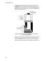
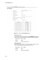
1
Unified Messaging
System
System Manual
Catalog No. 76-110-0887/0
Issue 1
Catalog No. 76-110-0887/0
Release 1.0
Issue 1
Unified Messaging System
System Manual
Telrad Tenecss Inc.
Woodbury, New York
NOTICE
This publication refers to the Telrad emaGEN Unified Messaging System, Release 1.0, Issue 1, connected to any of Telrad’s unite family of
telephone systems, Releases SB7/DB7/LB7, as of February 2002.
Telrad Tenecs, Inc. reserves the right to modify the equipment and software described herein without prior notice. However, changes made to
the equipment or to the software described herein do not necessarily
render this publication invalid.
This Issue 1 of the emaGEN System Manual is for internal use by Telrad Tenecs, Inc. employees only, and may not be distributed or reproduced, wholly or in part, without written permission from Telrad Tenecs,
Inc.
NOTE ON PRONUNCIATION
"unite" is pronounced:
yoo - nit - ee.
"emaGEN" is pronounced:
ee - ma - jen.
"eManager" is pronounced:
© 2002
Telrad Tenecs Inc.,
Woodbury, New York
ee - man - a - jer.
CONTENTS
Section 1 INTRODUCTION
1.1 MANUAL SCOPE....................................................................................... 1-1
1.2 STRUCTURE OF THE MANUAL ............................................................... 1-1
1.3 INTENDED AUDIENCE ............................................................................. 1-3
1.4 APPLICABLE DOCUMENTATION............................................................. 1-3
1.5 TYPOGRAPHICAL CONVENTIONS ......................................................... 1-4
Section 2 SYSTEM OVERVIEW
2.1 GENERAL .................................................................................................. 2-1
2.2 PRODUCT PROFILE ................................................................................. 2-1
2.3 emaGEN SYSTEM HARDWARE ............................................................. 2-5
2.3.1 The emaGEN-PC ........................................................................... 2-5
2.3.2 The emaGEN Voice Mail cards ...................................................... 2-5
2.3.3 OCD cards in the system cabinet..................................................... 2-6
2.4 emaGEN SYSTEM FEATURE OVERVIEW ............................................ 2-7
Section 3 INSTALLATION
3.1 GENERAL .................................................................................................. 3-1
3.2 INSTALLATION PLANNING ...................................................................... 3-1
3.3 INSTALLATION PREPARATIONS............................................................. 3-2
3.3.1 Reading the documentation ............................................................. 3-2
3.3.2 emaGEN-PC printed circuit cards .................................................. 3-2
3.3.3 OCD card preparation ...................................................................... 3-2
3.3.4 emaGEN voice mail ports definition ............................................... 3-3
3.4 OPTIMAL COMMUNICATION PORT PROVISIONING ............................. 3-3
3.4.1 General ............................................................................................ 3-3
3.4.2 Communication requirements per feature ........................................ 3-4
3.5 CRITICAL DISTANCES ............................................................................. 3-4
3.6 REQUIRED CABLES ................................................................................. 3-4
3.6.1 Data cable(s) from the emaGEN-PC to the OCD card(s) ............... 3-4
3.6.2 Audio cable(s) from the emaGEN-PC to the OCD card(s) ............. 3-5
3.7 HARDWARE INSTALLATION PROCESS ................................................. 3-6
3.8 INSTALLING emaGEN VOICE MAIL CARDS
IN THE emaGEN-PC............................................................................... 3-6
3.8.1 emaGEN voice mail card jumper settings ...................................... 3-6
3.8.2 emaGEN voice mail card insertion ................................................. 3-7
iii
CONTENTS (Continued)
3.9 SYSTEM PREPARATION AND CONNECTIONS TO emaGEN .............. 3-8
3.9.1 Mounting a MIM on an OCD card .................................................... 3-8
3.9.2 Inserting an OCD card into the system cabinet.............................. 3-10
3.9.3 Completing the data connection..................................................... 3-11
3.9.4 Performing the audio connection ................................................... 3-12
3.10 ADDITIONAL STEPS BEFORE ACTIVATING emaGEN ..................... 3-15
3.11 POWER CABLING ................................................................................. 3-16
3.12 MAIN DISTRIBUTION FRAME (MDF) CROSS CONNECTS ................ 3-16
3.13 PBX SOFTWARE CONSIDERATIONS .................................................. 3-17
3.13.1 Setting up the PBX to accommodate emaGEN .......................3-17
3.14 INSTALLING THE emaGEN SYSTEM ................................................. 3-18
3.15 QUICK STEPS FOR SOFTWARE INSTALLATION ............................... 3-18
3-16 CHECKLIST ........................................................................................... 3-19
3.17 CHECKING CABLING............................................................................ 3-20
3.18 CHECKING PRINTED CIRCUIT CARDS .............................................. 3-20
3.19 CHECKING SYSTEM CABINET TO MDF CONNECTIONS.................. 3-20
3.20 emaGEN SYSTEM DETAILED INSTALLATION INSTRUCTIONS....... 3-21
3.20.1 emaGEN Voice Mail full installation -- version 9 ......................... 3-21
3.21 INSTALLATION INSTRUCTIONS FOR ADDING ELEMENTS TO
THE emaGEN SYSTEM........................................................................ 3-28
3.21.1 How to add voice ports................................................................. 3-28
3.21.2 How to add fax ports .................................................................... 3-28
3.21.3 How to add modem ...................................................................... 3-28
3.21.4 How to add Unified messaging Push, POP, IMAP
and applet ..................................................................................... 3-28
3.21.5 How to add TTS ........................................................................... 3-39
3.21.6 How to add Speech Recognition ...................................................3.30
3.22 emaGEN SYSTEM DETAILED BACKUP AND RESTORE
INSTRUCTIONS ..................................................................................... 3-30
3.22.1 Back up option ............................................................................. 3-30
3.22.2 Restore option .............................................................................. 3-31
3.23 emaGEN SYSTEM DETAILED VERSION UPGRADE
INSTRUCTIONS ..................................................................................... 3-32
3.23.1 To view your current system version ............................................ 3-22
3.23.2 Connect to the emaGEN voice mail with FTP............................. 3-22
3.23.3 Extract and upgrade ..................................................................... 3-32
3.23.4 Verify correct system version ....................................................... 3-33
Section 4 OPERATION
4.1 GENERAL .................................................................................................. 4-1
4.2 CONVENTIONS ......................................................................................... 4-1
4.3 GENERAL RULES ..................................................................................... 4-1
4.3.1 System Prompts............................................................................... 4-1
iv
CONTENTS (Continued)
4.3.2 No Response from the user ............................................................. 4-1
4.3.3 Too many Errors .............................................................................. 4-2
4.3.4 Allowable time between key entries ................................................. 4-2
4.3.5 Use of the # key to terminate an entry ............................................. 4-2
4.3.6 Use of the * key ................................................................................ 4-2
4.4 FIRST-TIME USER TUTORIAL ................................................................. 4-3
4.5 DIRECTORY TREE.................................................................................... 4-3
Section 5 SYSTEM ADMINISTRATION
5.1 GENERAL .................................................................................................. 5-1
5.2 CONNECTING TO emaGEN.................................................................... 5-1
5.2.1 Data Connection .............................................................................. 5-1
5.2.2 Modem Connection .......................................................................... 5-2
5.2.3 Null- Modem Connection.................................................................. 5-4
5.3 ftp Access ................................................................................................... 5-4
5.4 emaGEN T3Adm ..............................................................................5-5
5.4.1 Logging in – “telnet” ......................................................................... 5-5
5.4.2 emaGEN T3adm options ............................................................... 5-5
5.4.3 Service ............................................................................................. 5-6
5.4.4 Network configuration -- option 4 ..................................................... 5-7
5.4.5 System Backup -- option 5 ............................................................... 5-7
5.4.6 System Monitor -- option 6 ............................................................... 5-8
5.4.7 A1 Info -- option 7............................................................................. 5-8
5.4.8 Verify Installation -- option 8 ............................................................. 5-8
5.4.9 Shut down -- option 9 ....................................................................... 5-8
5.4.10 Extra stuff -- option 10 .................................................................... 5-8
5.4.11 Import/Export Data Base................................................................ 5-9
5.4.12 Select PBX ..................................................................................... 5-9
5.4.13 Configure voice card board ............................................................ 5-9
5.4.14 Define modem .............................................................................. 5-10
5.4.15 Configure Fax............................................................................... 5-10
5.4.16 Installing the Fax software ............................................................5-11
5.5 emaGEN MONITOR....................................................................... 5-11
5.6 emaGEN CONTROLLER ...............................................................5-12
5.7 emaGEN SYSTEM MESSAGE CALL RECORDING (SMDR) .......5-12
5.7.1 Accessing SMDR Reports.............................................................. 5-12
5.7.2 Generating a report ........................................................................ 5-12
5.7.3 Costing of calls ............................................................................... 5-13
Section 6 emaGEN WEB CONTROLLER
6.1 THE emaGEN WEB CONTROLLER SCREEN........................................ 6-1
6.2 THE emaGEN WEB ADMINISTRATION UTILITY.................................... 6-1
6.3 TO USE THE emaGEN WEB CONTROLLER.......................................... 6-1
6.4 NAVIGATING THE SYSTEM .................................................................... 6-2
v
CONTENTS (Continued)
Section 7 SITE
7.1 GENERAL ..........................................................................................7-1
7.2 SITE -- GENERAL INFORMATION............................................................ 7-2
7.3 THE SITE SETTINGS SCREEN ................................................................ 7-5
7.4 PARAMETERS ON THE SITE --> SETTINGS SCREEN ........................... 7-5
7.5 SPECIAL KEY PARAMETERS ON THE SITE --> SETTINGS SCREEN .. 7-7
7.6 SECURITY PARAMETERS ON THE SITE --> SETTINGS SCREEN........ 7-8
7.7 GREETING HOURS PARAMETERS ON THE SITE --> SETTINGS
SCREEN ................................................................................................... 7-8
7.8 HOUSEKEEPING PARAMETERS ON THE SITE --> SETTINGS
SCREEN .................................................................................................... 7-9
7.9 SYSTEM PARAMETERS ON THE SITE --> SETTINGS SCREEN ......... 7-10
7.10 CALL OUT PARAMETERS ON THE SITE --> SETTINGS SCREEN .....7-11
7.11 PUBLIC ANNOUNCEMENT PARAMETERS......................................... 7-12
7.12 HOLIDAY SCHEDULE ........................................................................... 7-13
7.13 CID ROUTING........................................................................................ 7-15
Section 8 PBX PORT DEFINITION
8.1 GENERAL ..........................................................................................8-1
8.2 PORT PARAMETERS .........................................................................8-1
Section 9 PBX
9.1 THE PBX --> PARAMETERS SCREEN.................................................9-1
9.2 GENERAL PBX PARAMETERS ...........................................................9-2
9.3 DISCONNECT............................................................................................ 9-2
9.4 IN-BAND INTEGRATION ........................................................................... 9-4
9.5 TRANSFER TO EXTENSIONS.................................................................. 9-5
9.6 MESSAGE WAITING INDICATOR ............................................................. 9-6
9.7 DIAL STRINGS .......................................................................................... 9-7
9.8 RECONNECT SEQUENCES ..................................................................... 9-8
9.8.1 Message Waiting Indicator .............................................................. 9-9
9.9 PBX TIMERS............................................................................................ 9-11
9.10 DISCONNECT DETECTION.................................................................. 9-12
9.11 INTEGRATION PARAMETERS ............................................................. 9-14
9.11.1 DTMF Integration commands...................................................... 9-16
9.12 CONFERENCE SEQUENCE ................................................................. 9-19
9.13 TRUNK INTEGRATION TABLE ............................................................. 9-21
9.14 RS232 INTEGRATION TABLE ............................................................... 9-22
vi
CONTENTS (Continued)
Section 10 DEPARTMENTS
10.1 DEPARTMENT DEFINITION ............................................................10-1
10.1.1 Recording system greetings......................................................... 10-2
10.1.2 Conversion table .......................................................................... 10-2
10.1.3 Using a script instead of the standard automated attendant ........ 10-3
10.2 DEPARTMENT -- PROPERTIES GENERAL SETTINGS ..................... 10-3
10.3 DEPARTMENT -- PROPERTIES DIRECTORY MODE ........................ 10-6
10.4 DEPARTMENT --> WORKING HOURS ................................................ 10-7
10.5 DEPARTMENT -- PROPERTIES CONVERSION TABLE ...................... 10-8
10.6 DEPARTMENT --> DIRECTORY ASSISTANCE .................................... 10-9
10.6.1 Speech recognition automated attendant .................................... 10-9
10.6.2 Key press directory assistance .................................................. 10-10
10.6.3 Adding and removing names ..................................................... 10-10
10.7 SETTING UP SPEECH RECOGNITION...............................................10-11
10.7.1 Defining names ...........................................................................10-11
10.7.2 Adding names to the pronunciation table................................... 10-13
Section 11 MAILBOX
11.1 MAILBOX MAINTENANCE .............................................................. 11-1
11.2 ESSENTIAL FIELDS TO SET WHEN CREATING
NEW MAILBOXES ........................................................................... 11-2
11.3 CREATING A MAILBOX .................................................................. 11-2
11.4 MAILBOX PROPERTIES FIELDS...........................................................11-3
11.5 TRANSFER CALLS................................................................................ 11-9
11.6 WAKE UP CALLS ................................................................................ 11-12
11.7 CONVERSION TABLE......................................................................... 11-14
11.8 MESSAGE NOTIFICATION ................................................................. 11-16
11.8.1 Bin information fields ...................................................................11-18
11.8.2 Schedule table entries.................................................................11-19
11.9 EMAIL SETTINGS................................................................................ 11-24
11.9.1 Enabling the email client .............................................................11-25
11.9.2 Setting up the email client for POP3 ...........................................11-25
11.9.3 Setting up the email client for IMAP ............................................11-26
11.9.4 Setting up Send-Mail...................................................................11-27
11.10 POP3 ACCOUNTS............................................................................. 11-28
11.10.1 Synchronize email .................................................................... 11-29
11.11 EMAIL REPLY SETTINGS ................................................................. 11-29
11.12 FORWARDING OPTIONS ................................................................. 11-30
10.12.1 Actions ..................................................................................... 11-31
Section 12 CLASS OF SERVICE
12.1 GENERAL .............................................................................................. 12-1
vii
CONTENTS (Continued)
12.2 PERSONAL OPTIONS........................................................................... 12-3
12.3 MESSAGES ........................................................................................... 12-5
12.4 INCOMING CALLS................................................................................. 12-7
12.4.1 Ringer MWI .................................................................................. 12-9
12.5 HOUSEKEEPING................................................................................. 12-10
Section 13 GROUPS
13.1 GENERAL .............................................................................................. 13-1
13.2 CREATING A NEW GROUP.................................................................. 13-3
13.3 REMOVING A GROUP .......................................................................... 13-3
13.4 ADDING MEMBERS TO A GROUP....................................................... 13-3
13.5 REMOVING MEMMBERS FROM A GROUP ........................................ 13-3
Section 14 SCRIPTS
14.1 INTRODUCTION.................................................................................... 14-1
14.2 CREATING A SCRIPT -- AN OVERVIEW.............................................. 14-1
14.3 RECORDING A SCRIPT VOICE FILE ................................................... 14-3
14.4 SCRIPT PROGRAMMING ..................................................................... 14-3
14.4.1 Action Function Descriptions........................................................ 14-4
14.4.2 OK / Err and Numeric entry column fields .................................... 14-8
14.4.3 Script function examples .............................................................. 14-9
Section 15 THE SYSTEM ADMINISTRATOR
15.1 THE SYSTEM ADMINISTRATOR.......................................................... 15-1
15.2 ASSIGNING AN ADMINISTRATOR ....................................................... 15-1
15.3 ADMINISTRATOR’S REMOTE OPERATIONS ..................................... 15-2
15.3.1 Administration menu .................................................................... 15-2
15.3.2 Emergency greeting menu ........................................................... 15-3
15.3.3 Record greeting menu.................................................................. 15-3
15.3.4 Greeting review menu .................................................................. 15-4
15.3.5 Prompt selection menu ................................................................ 15-5
15.3.6 Record prompt menu ................................................................... 15-5
15.3.7 Prompt review menu .................................................................... 15-6
15.3.8 Destination entry menu ................................................................ 15-6
15.3.9 Password menu ........................................................................... 15-7
15.3.10 Operation mode menu ............................................................... 15-7
15.3.11 Record names mailbox selection ............................................... 15-8
15.3.12 Group name selection ................................................................ 15-9
15.3.13 Time or date menu ..................................................................... 15-9
15.3.14 Mailbox administration ............................................................. 15-10
15.4 GENERAL COMPANY VOICE PROMPTS .......................................... 15-11
viii
CONTENTS (Continued)
Section 16 VOICE PROMPTS
16.1 GENERAL .............................................................................................. 16-1
16.2 VOICE PROMPT LIST ........................................................................... 16-2
Section 17 REPORTS
17.1 REPORT TYPES.................................................................................... 17-1
17.2 MAILBOX LIST....................................................................................... 17-2
17.3 MAILBOX USAGE.................................................................................. 17-2
17.3.1 Mailbox usage by date ................................................................. 17-2
17.3.2 Mailbox usage daily...................................................................... 17-2
17.3.3 Mailbox usage daily detail ............................................................ 17-3
17.4 SYSTEM GROUP LISTS ....................................................................... 17-3
17.5 PORT STATISTICS................................................................................ 17-4
17.6 SYSTEM STATISTICS........................................................................... 17-4
17.7 HOURLY SYSTEM STATISTICS........................................................... 17-5
17.8 OUTBOUND CALLS .............................................................................. 17-6
17.9 FULL REPORTS .................................................................................... 17-6
Section 18 FAX
18.1 INTRODUCTION.................................................................................... 18-1
18.2 FAX PARAMETERS............................................................................... 18-1
18.3 FAX LINES ............................................................................................. 18-4
18.4 FAX MAIL ............................................................................................... 18-4
18.4.1 Receiving Faxes........................................................................... 18-4
18.4.2 Retrieving Faxes .......................................................................... 18-4
18.5 FAX-ON DEMAND ................................................................................. 18-4
18.5.1 General ........................................................................................ 18-4
18.5.2 Same Call (One-To-One) ............................................................. 18-5
18.5.3 Return Call (Dedicated line) ......................................................... 18-5
18.5.4 Same Call and Return Call combination ...................................... 18-5
18.5.5 Fax Function Descriptions............................................................ 18-5
Section 19
eManager PROGRAMMING FOR emaGEN IN unite SYSTEMS
19.1 GENERAL .............................................................................................. 19-1
19.2 SYSTEM CONFIGURATION PROGRAMMING .................................... 19-1
19.2.1 Card Configuration Screen........................................................... 19-1
19.2.2 IVM/serial applications Screen ..................................................... 19-3
19.2.3 emaGEN configurations ............................................................. 19-6
19.3 DEFINING THE emaGEN HUNT GROUP ........................................... 19-7
19.4 DEFINING THE IVM HUNT GROUP ................................................... 19-10
19.5 RING ROUTING................................................................................... 19-11
ix
CONTENTS (Continued)
19.6 ASSIGNING A MAILBOX NUMBER AND TENANT STATUS ............. 19-12
19.7 ASSIGNING INTERCOM RESTRICTION............................................ 19-13
19.8 STATION FEATURE PROGRAMMABLE BUTTONS .......................... 19-14
19.8.1 Programmable Keys Selection and Station Maps Screen ......... 19-14
19.9 ATTENDANT FEATURES PROGRAMMING....................................... 19-17
19.9.1 Programmable Keys and Attendant Definition Screen ............... 19-17
19.10 AUTOMATIC CALL DISTRIBUTION PROGRAMMING..................... 19-17
19.10.1 ACD Routing Plans Screen ..................................................... 19-18
19.10.2 Interflow/overflow Programming Screen ................................. 19-19
19.10.3 Announcer Plans Screen ........................................................ 19-20
19.10.4 Announcement Program Screen............................................. 19-21
19.11 PABX/CENTREX................................................................................ 19-21
19.11.1 System Timers Screen ............................................................ 19-21
19.12 IMPLEMENTING A NETWORKED emaGEN SYSTEM ................... 19-22
19.12.1 IVM hunt group in a network ................................................... 19-22
INDEX
TABLES
3-1 I/O port jumper settings ....................................................................................... 3-7
3-2 Connections of data cable from emaGEN card to OCD card .......................... 3-12
19-1 Station types ................................................................................................. 19-15
FIGURES
2-1
2-2
2-3
emaGEN connections with the unite system .................................................. 2-7
emaGEN Operation Menu feature overview ..................................................... 2-8
emaGEN Administration Menu feature overview .............................................. 2-8
3-1
3-2
3-3
3-4
3-5
3-6
Wrist strap guarding against electrostatic discharge ......................................... 3-8
Inserting the MIM on the OCD card ................................................................. 3-10
OCD card insertion .......................................................................................... 3-11
Data cable from emaGEN card to OCD card ................................................. 3-12
emaGEN cabling from emaGEN-PC to OCD card ....................................... 3-13
Audio cable from emaGEN voice mail card
to four port junction box .................................................................................. 3-14
3-7 Typical 25-pair cable connector from OCD block in MDF ................................ 3-15
5-1 Crossover Cable Diagram .................................................................................. 5-2
5-2 emaGEN Monitor screen................................................................................. 5-11
5-3 emaGEN Controller Main Menu screen .......................................................... 5-12
5-4 SMDR Reports definition screen ...................................................................... 5-13
5-5 Sample SMDR Report ...................................................................................... 5-15
x
CONTENTS (Continued)
FIGURES (Continued)
6-1 emaGEN Web Controller Main Menu screen ................................................... 6-1
6-2 Your guide to emaGEN screens and instructions ............................................... 6-3
7-1
7-2
7-3
7-4
7-5
Site -->
Site -->
Site -->
Site -->
Site -->
General Screen ...................................................................................... 7-1
Settings Screen...................................................................................... 7-5
Public Announcement screen .............................................................. 7-12
Holiday Schedule screen ..................................................................... 7-13
CID Routing screen.............................................................................. 7-15
8-1 PBX --> Port Definition screen............................................................................ 8-1
9-1
9-2
9-3
9-4
10-1
10-2
10-3
10-4
PBX
PBX
PBX
PBX
-->
-->
-->
-->
Parameters screen................................................................................ 9-1
Integration screen ............................................................................... 9-14
Trunk Integration screen ..................................................................... 9-21
Serial Integration screen ..................................................................... 9-22
Department --> Properties screen .................................................................. 10-1
Department --> Working Hours screen ........................................................... 10-7
Department --> Directory Assistance screen .................................................. 10-9
Site --> Speech Recognition screen ............................................................. 10-12
11-1 Mailbox --> Properties screen .......................................................................... 11-1
11-2 Mailbox Toolbar ............................................................................................... 11-2
11-3 Create New Mailbox screen ............................................................................. 11-3
11-4 Mailbox --> Conversion Table screen ............................................................ 11-14
11-4 Mailbox --> Message Notification screen ....................................................... 11-27
11-5 Mailbox --> Email Settings screen ................................................................. 11-24
11-7 Mailbox --> POP3 Accounts screen............................................................... 11-28
11-8 Mailbox --> Email Reply Settings screen ....................................................... 11-29
11-9 Mailbox --> Forwarding Options screen ......................................................... 11-30
12-1 Class of Service screen ................................................................................... 12-2
13-1 Site --> General --> Global Groups screen ...................................................... 13-2
13-2 Mailbox --> Groups screen .............................................................................. 13-2
13-3 Mailbox --> Group Members screen ................................................................ 13-4
14-1 Mailbox --> Script screen ................................................................................. 14-2
17-1 Reports --> Main Menu screen ........................................................................ 17-1
18-1 Site --> Fax Settings screen ............................................................................ 18-2
xi
CONTENTS (Continued)
THIS PAGE INTENTIONALLY BLANK
xii
Section 1
INTRODUCTION
1.1
MANUAL SCOPE
This manual presents the information needed to install and
program the emaGEN Unified Messaging System in
conjunction with the unite family of systems. This information
includes an overview of the emaGEN system, hardware and
software installation procedures and instructions for
programming emaGEN and its many features.
1.2
STRUCTURE OF THE MANUAL
This manual is divided into the following sections:
1. INTRODUCTION
Provides introductory information about emaGEN system
documentation.
2. SYSTEM OVERVIEW
Provides a general overview of emaGEN capabilities,
basic concepts and features.
3. INSTALLATION
Provides information required for emaGEN system installation planning and preparations.
4. OPERATION
Provides basic information on emaGEN system operation.
5. SYSTEM ADMINISTRATION
Provides basic information on emaGEN system administration.
6. emaGEN WEB CONTROLLER
Provides an introduction to the emaGEN Web Controller -the administration utility of the emaGEN system.
1-1
76-110-0887/0, Issue 1
7. SITE
Provides administration definition instructions for adapting emaGEN to your specific site.
8. PBX PORT DEFINITION
Provides administration definition instructions for your telephone
system outside line ports.
9. PBX
Provides administration definition instructions for your telephone
system parameters, integration and outside lines.
10. DEPARTMENTS
Provides administration definition instructions for configuring the
emaGEN automated attendant to each department on your
site.
11. MAILBOX
Provides administration definition instructions for maximum utilization of mailbox features, properties and options.
12. CLASS OF SERVICE
Provides administration definition instructions for assigning a
Class of Service to each mailbox, to control its activities.
13. GROUPS
Provides administration definition instructions for assigning, controlling and linking mailbox groups, in various configurations.
14. SCRIPTS
Provides detailed instructions for creating and utilizing customized routines, called scripts.
15. THE SYSTEM ADMINISTRATOR
Provides information on the assignment and functions of the
System Administrator.
16. VOICE PROMPTS
Provides describes the organization, structure and utilization of
system greeting voice prompts.
17. REPORTS
Provides standard structure and information details contained in
a series of statistical reports, used to enable the System Administrator to keep track of emaGEN system activity.
18. FAX
Provides administration definition instructions for maximum utilization of fax parameters, facilitating fax mail, fax-on-demand
and fax integration with mailboxes and email.
1-2
Section 1: INTRODUCTION
19.PROGRAMMING FOR emaGEN IN unite SYSTEMS
Provides a description of unite system programming requirements -- applied using the Windows-based eManager -- for
emaGEN implementation.
1.3
INTENDED AUDIENCE
This manual is intended for field technicians and for the System
Administrator responsible for maintaining the
Messaging System.
emaGEN Unified
The manual assumes the reader is familiar with unite system
programming and with personal computers.
1.4
APPLICABLE DOCUMENTATION
In addition to this system manual, the following
documentation is available:
•
emaGEN
emaGEN Client User Guide
Catalog number 76-110-0888/0
•
emaGEN Quick Reference Guide (English)
Catalog number 76-110-0889/0
•
emaGEN User Guide for Avanti 3025 set
Catalog number 76-110-0891/0
•
emaGEN User Guide for Avanti 3020 and 3015D sets
Catalog number 76-110-0892/0
•
emaGEN User Guide for All Types of Telephone Sets
Catalog number 76-110-0893/0
You should also be familiar with the Release 6 and Release 7 documentation for the unite Family of systems, including:
• Feature Description -- Release 6
Catalog number 76-110-0690/F.
• Feature Description Addendum -- Release 7
Catalog number 76-110-0690/G.
• Hardware Description -- Release 6
Catalog number 76-110-0685/F.
1-3
76-110-0887/0, Issue 1
• 19 inch System Cabinet Administration and Installation
Addendum -- Release 7
Catalog number 76-110-0881/0
• Operating Instructions -- Release 6
Catalog number 76-110-0165/F.
• Operating Instruction Addendum -- Release 7
Catalog number 76-110-0165/G
• Administration Manual -- Release 6
Catalog number 76-110-0175/F.
• Administration Forms -- Release 6
Catalog number 76-110-0405/F.
• Administration, Installation and Upgrade Addendum
-- Release 7
Catalog number 76-110-0175/G
• Installation Manual -- Release 6
Catalog number 76-110-0410/F.
• Maintenance manual -- Release 7
Catalog number 76-110-0170/G
1.5
TYPOGRAPHIC CONVENTIONS
Throughout this manual, the following typographic conventions
have been used:
• Keys on the telephone set are shown like this:
[MSG], [SPKR], [REDIAL], [7].
• Text appearing on the telephone display is shown like this:
ADD ON, ENTER DN.
• Keys on the computer keyboard appear capitalized, like this:
ENTER, ESC, F9.
• Text to be typed on the computer keyboard exactly as indicated,
is shown like this:
p, e1, 42.
• Text appearing on the computer screen is shown like this:
CALLS WAITING, 13:20.
• Names of screens or menus are shown like this:
SYSTEM TIMERS Screen.
• Names of Microsoft Windows icons, windows and dialog boxes
are shown like this:
Advanced Options.
• Movement from one configuration screen to another appears
showing the code letters for the screens as follows:
Y−S.
• Buttons appearing under Microsoft Windows are shown like this:
Change name.
1-4
Section 2
SYSTEM OVERVIEW
2.1
GENERAL
This section provides a general overview of Telrad emaGEN
system capabilities and features. It details the features of the
emaGEN system and describes its physical connection with
the unite family of systems, including the following systems:
2.2
•
unite 128
•
unite 8/18
•
unite 400
•
unite 60
•
unite 1000
PRODUCT PROFILE
Telrad emaGEN is a value added comprehensive voice processing application platform, providing services suh as voice
mail, unified messaging, automated attendant and automated
voice response. It connects to a unite telephone system
through analog ports, and is administered locally or remotely
using TCP/IP interface.
emaGEN is designed with the installer in mind. There are
many in-depth parameters to adjust the system for different
telephone systems and different site configurations, but the
common installation can be completed without changing almost
any parameters. A pre-defined library of PBXs is included for
your convenience, and during the installation you’ll only need to
select the type of PBX you are installing emaGEN on.
emaGEN is fully integrated with your unite system, as demonstrated by the following features:
• Direct communication is established between the emaGEN
processor and the unite system central processing unit.
•
emaGEN integrates voice and data within the unite system and provides an almost unlimited number of up to
2-1
76-110-0887/0, Issue 1
seven digit mailboxes for message storage -- within the limits of
the installed system platform.
•
emaGEN leaves messages on your unite system telephone
set display. Users access emaGEN through the normal message answering procedure. You can also access emaGEN with
softkeys from unite system Avanti 3025, Avanti 3020 and Avanti
3015D telephone sets and the Executive telephone set with
expanded display.
• Calls can be forwarded from your telephone set to emaGEN or
from emaGEN to your telephone set.
•
emaGEN knows how to distinguish between incoming internal
and external calls and handles the calls accordingly.
• unite system Avanti 3025, Avanti 3020 and Avanti 3015D telephone sets and the Executive telephone set with expanded display provide softkeys and menu prompts for enhanced
emaGEN feature operation.
• Information on received email and fax messages can be heard
on unite system telephone sets -- utlizing text to speech technology -- and can be viewed on telephone set displays.
• Programmable keys on your telephone sets, if any, can be programmed to give you immediate access to emaGEN features,
such as to your mailbox, to call recording, call screening and
message monitoring.
• The message monitoring feature allows the user to hear a message that is being recorded in her mailbox and to intercept that
call if she chooses.
• System Dial By Name option allows you to rapidly call your
desired party without even knowing their extension number.
•
emaGEN can be configured with up to 28 voice mail ports, in all
unite systems.
Every four emaGEN voice mail ports are connected to the system cabinet via their respective MIM module on the Option (OCD)
cards.
• Menu-driven emaGEN software leads you through easy to
understand setup procedures. Configuration and administration
tasks are intuitive and simple to learn.
• Most of the system features can be programmed by an authorized user, by means of a browser and modem, or by direct con-
2-2
Section 2: SYSTEM OVERVIEW
nection to emaGEN, from any unite system telephone set, or
any DTMF telephone.
• When answered by the automated attendant, outside callers follow recorded instructions which explain how to dial directly to the
extension of their choice or how to use the Automated Attendant
Dial By Name feature to reach their desired party. This feature
provides the convenience of direct inward dialing on outside
lines, and, since these calls are not transferred via an attendant,
it reduces the burden on the attendant position. emaGEN can
also double as an after-hours office attendant.
• An outside call to an emaGEN subscriber can be forwarded by
the automated attendant to that subscriber’s outside number (or
mailbox or alternative internal location), by utilizing the unite
system’s outside line patch feature. This approach can be useful
when, for example, the subscriber’s extension number is busy or
does not answer, or when that subscriber only has an external
number and no internal extension.
• A call to an outside party on an external line behind Centrex or a
PABX (private automatic branch exchange) can be enabled, by
having emaGEN initiate the flash signaling required for placing
such a call.
•
emaGEN voice mail is a sophisticated, reliable and confidential
solution to the problem of unanswered calls. A caller who
receives no answer at an extension, is connected to emaGEN
voice mail to hear the mailbox owner's prerecorded personal
opening greeting. The caller can then record and edit a voice
message in the called user's mailbox.
• With emaGEN, your telephone set display indicates that a voice
message was recorded in your mailbox -- or, if there is more than
one message, it shows the number of messages in the mailbox.
You can access your mailbox at the touch of a button.
• The user of a unite system Avanti 3025, Avanti 3020 and Avanti
3015D telephone set or Executive telephone set with an
expanded display has the option of reviewing waiting messages
by means of a visual message list displayed on his telephone
set. Once the Visual message review feature has been activated,
the number of waiting new, urgent and old messages appear, as
well as the number of messages prepared by the user for future
delivery and the number of messages to be certified by the user.
After selecting one of these message categories, you can then
scroll through the list -- up to five messages per display page -and handle each message as you deem appropriate.
2-3
76-110-0887/0, Issue 1
• The user of a unite system Avanti 3025, Avanti 3020 and Avanti
3015D telephone set or Executive set with expanded display can
view a list of incoming outside calls, provided that the Central
Office supports Caller ID for those calls. These calls are differentiated between those that were answered and those that were
not answered. The user can toggle between a display of the
caller’s name or the caller’s number. If the user is authorized to
enter the mailbox of another extension, she can also view the list
of incoming outside calls for that extension.
The user can return any of those calls simply by pressing the
associated softkey.
• With the Caller ID Routing Feature, an incoming call can be classified -- by the area code, office code and/or other elements of
the originating telephone number -- and routed to the system
extension of a corresponding staff member.
•
emaGEN allows the technician to exit the system, when necessary, without disconnecting calls currently being handled. When
all system ports are released, the exit is automatically executed.
All mailbox owners review messages deposited in their mailbox and
can then select one of many options such as replay, save or erase
the message, or send or copy the message to other mailboxes.
All access to mailbox messages and greeting changes is controlled
by passwords to ensure totally confidential communications.
Advanced subscriber functions include the ability to screen incoming calls, record a call in progress, tag messages with date and time
information, index old messages, fast forward messages, record
group messages, perform interviews, program comprehensive call
handling parameters, and forward message reminders to internal or
outside numbers, including pagers.
Advanced system functions include announcer messages, a system
directory which can locate a desired number and dial it, automatic
disk maintenance capability, recorded announcements for hunt
groups, up to 50 recorded announcements for ACD groups, and
coordinated day/night control between emaGEN and the unite
system cabinet. An emaGEN system can also be used to serve the
voice mail needs of a number of networked unite systems. See
Section 19.12 for unite networking programming requirements.
2-4
Section 2: SYSTEM OVERVIEW
NOTE
emaGEN is a versatile system with many
programmable variations. Unless otherwise
specified, this manual presents the default
operation and settings of programmable
features and parameters.
2.3
2.3.1
emaGEN SYSTEM HARDWARE
The emaGEN-PC
The emaGEN system is based on a dedicated personal computer,
termed the emaGEN-PC, fitted with additional printed circuit cards,
as required for full operation of the purchased system.
2.3.2
The emaGEN Voice Mail cards
emaGEN can be configured with up to 28 voice mail ports, in all
unite systems.
The emaGEN-PC must be fitted with emaGEN printed circuit
cards,depending on the number of emaGEN ports you wish to
establish in your system. There are several types of emaGEN four
telephony port and two port voice processing cards,manufactured
by Brooktrout Technology, to choose from, in order to setup your
system, as detailed in Section 3.3.2, below.
The emaGEN-PC can thus have any even number config-uration
of emaGEN ports -- from 2 to 28 ports, as follows:
• One four-port card, for a four-port emaGEN system;
• Two four-port cards, for an eight-port emaGEN system;
• Three four-port cards, for a 12-port emaGEN system;
• Four four-port cards, for a 16-port emaGEN system.
• Five four-port cards, for a 20-port emaGEN system;
• Six four-port cards, for a 24-port emaGEN system;
• Seven four-port cards, for a 28-port emaGEN system.
The emaGEN cards are connected to OCD card(s) installed in the
respective unite system cabinet, as described in Section 3.9,
below.
2-5
76-110-0887/0, Issue 1
2.3.3
OCD cards in the system cabinet
emaGEN can be configured with up to 28 voice mail ports, in all
unite systems.
The required audio and data connections are made between ema-
GEN card(s) in the emaGEN-PC and OCD card(s) in the unite
system cabinet. These connections consist of:
• Data connection: from the emaGEN-PC com port, via a threewire cable to the RJ45 connector on the outside end of the first
OCD card holding MIMs. A similar cable must be connected to a
second and third OCD card (if present) each of which contains
an MIM module(s) supporting emaGEN ports.
• Audio connection: from each emaGEN-PC card, via two twopair cables to a junction box and the MDF, and via a 25-pair
cable from the MDF to the 25-pair connector on the outside end
of each OCD card.
NOTE
A 16 to 24 port emaGEN configuration
must use two OCD cards.
A 28 port emaGEN configuration must use
three OCD cards.
Figure 2-1, below, shows the physical connections between an
emaGEN card and the unite system.
2-6
Section 2: SYSTEM OVERVIEW
O C D card in system cabinet
D ata cable from
PC to O C D card
MDF
Audio cable/s from junction box to M D F
Junction box
Tw o tw o-pair audio cables from
PC card to junction box
Voice m ail card
installed in the P C
S ta n d ard 2 5 -p a ir ca b le /s fro m M D F
J1
J2
PC
PC com port
Figure 2-1
2.4
emaGEN connections with the unite system
emaGEN SYSTEM MENU FEATURE OVERVIEW
Figures 2-2 and 2-3, below, present overviews of emaGEN Operation features and Administration features menu processing, respectively. Refer to these figures, as necessary, to follow the emaGEN
processing flow and see the features involved.
Knowing the capabilities of each emaGEN feature is the key to obtaining the maximum amount of service and benefit to your organization. Many features have user-defined parameters that you must
program. This customized programming allows you to maximally tailor emaGEN to the specific needs of your organization.
2-7
76-110-0887/0, Issue 1
2/5 /HDYH D 0HVVDJH
1/7/8 /LVWHQ WR 1HZ 'HOHWHG 0HVVDJH
)XWXUH 0HVVDJHV
*URXS
6HOHFW 0DLOER[ RU *URXS
9 9LVXDO OLVW
3 3HUVRQDO *UHHWLQJV
1
2
3
4
5
5HFRUG
1RUPDO JUHHWLQJ
%XV\ JUHHWLQJ
1DPH
7HPSRUDU\ JUHHWLQJ
,QWHUQDO JUHHWLQJ
4 0DLOER[ RSWLRQV
1
2
6
&DOO RXW RSWLRQV
3DVVZRUG
*URXS OLVWV
1
2
3
4
5
6
)RUZDUG &RS\ PHQX
&RS\ WR PDLOER[
)RUZDUG WR PDLOER[
&RS\ WR JURXS
)RUZDUG WR JURXS
&RS\ WR PXOWLSOH PDLOER[HV
)RUZDUG WR PXOWLSOH PDLOER[HV
1
2
3
4
$QQRWDWLRQ
6HQG QRZ
&DQFHO
6HW RSWLRQV
1
2
3
0HVVDJH RSWLRQV
8UJHQW 3ULRULW\
&RQILGHQWLDO
&RQILUPDWLRQ 5HWXUQ UHFHLSW
1
2
3
4
5
*URXS OLVWV
&UHDWH OLVW
5HFRUG OLVW QDPH
'HOHWH OLVW
0HPEHU RSWLRQV
/LQN RSWLRQV
1
2
(QWHU QHZ SDVVZRUG
'HOHWH SDVVZRUG
# &DOOHU ,' OLVW
$IWHU 5HFRUG 0HQX
0 6\VWHP DGPLQLVWUDWRU
5HYLHZ PHVVDJHW
6DYH DQG VHQG PHVVDJH
(UDVH PHVVDJH
$GG WR PHVVDJH
(UDVH DQG UHUHFRUG
0HVVDJH RSWLRQV
1
2
3
4
5
6
1
2
3
4
5
6
*UHHWLQJ 5HYLHZ 0HQX
5HYLHZ JUHHWLQJ
6DYH JUHHWLQJ
(UDVH JUHHWLQJ
$GG WR JUHHWLQJ
(UDVH DQG UHUHFRUG
5HUHFRUG ZLWK DPSOLILFDWLRQ
0HVVDJH RSWLRQV
1
2
3
4
8UJHQW 3ULRULW\
&RQILGHQWLDO
&RQILUPDWLRQ 5HWXUQ UHFHLSW
)XWXUH GHOLYHU\
0HVVDJH QRWLILFDWLRQ
$FWLYDWH 'HDFWLYDWH
(GLW OLQHV
1
2
1
2
3
1
2
&DOO RXW RSWLRQV
0HVVDJH QRWLILFDWLRQ
&DOO FRQIHUHQFLQJ )ROORZ PH
:DNH XS FDOO
:HHNGD\V :HHNHQG
:HHNGD\V
:HHNHQG
:DNH XS FDOO
1
2
3
1
2
&DOO FRQIHUHQFLQJ )ROORZ PH
$FWLYDWH 'HDFWLYDWH
&DOORXW QXPEHU
1 (PHUJHQF\ *UHHWLQJ
5HYLHZ
'HOHWH
5HFRUG
2 5HFRUG SURPSWV
3 3DVVZRUGV
6HOHFW SURPSW IROORZHG E\ #
6HOHFW PDLOER[
1
2
3
1
2
6 *URXS OLVWV
1
2
3
4
5
1
2
Figure 2-3
2-8
5HYLHZ
'HOHWH
5HFRUG
1
2
0HVVDJH UHYLHZ IRU 1HZ 6DYHG &RQILUPHG ,QGH[HG (PDLO
1
2
3
4
5
6
7
8
9
0
1
2
3
4
5
6
7
8
9
3DVVZRUG
1HZ
'HOHWH
4 2SHUDWLRQ 0RGH
1
2
3
4
5
'D\
/XQFK
1LJKW
(PHUJHQF\
$XWRPDWLF
$IWHU UHFRUG PHQX
6DYH
5HYLHZ
7 6\VWHP WLPH DQG GDWH
&UHDWH OLVW
5HFRUG OLVW QDPH
'HOHWH OLVW
0HPEHU RSWLRQV
/LQN RSWLRQV
1HZ
6DYHG
)XWXUH GHOLYHU\
&RQILUPHG
,QGH[HG
(PDLO
)D[
5HSHDW
6DYH ! 1H[W PHVVDJH
(UDVH ! 1H[W PHVVDJH
5HSO\
)RUZDUG &RS\
0HVVDJH RSWLRQV
5HZLQG
3DXVH
)RUZDUG
6DYH DV QHZ
0HVVDJH RSWLRQV
/RZ YROXPH
1RUPDO YROXPH
+LJK 9ROXPH
/RZ VSHHG
1RUPDO VSHHG
+LJK VSHHG
6DYH DV QHZ
,QGH[ PHVVDJH
5HSHDW ZLWK HQYHORSH
LQIRUPDWLRQ
emaGEN Operation Menu feature overview
Figure 2-2
1
2
3
$FWLYDWH 'HDFWLYDWH
:DNH XS WLPH
&DOORXW QXPEHU
6 0HVVDJH &DWHJRULHV
1
2
3
4
5
6
7
7LPH
'DWH
8 0DLOER[ DGPLQLVWUDWLRQ
2
3
4
5
$GG
'HOHWH
(GLW
5HVHW 0:,
emaGEN Administration Menu feature overview
5 1DPHV
6HOHFW PDLOER[
5HFRUG QDPH
Section 3
INSTALLATION
3.1
GENERAL
Sections 3.2 through Section 3.6, below, describe planning and
component requirements for the installation of the
tem, .
emaGEN sys-
Section 3.7 through Section 3.16, below, describe the procedure for
installing the physical components of emaGEN within the ema-
GEN-PC, and the connections between the emaGEN-PC and the
unite system.
Section 3.17 through Section 3.21, below, describe post-installation
checkout and troubleshooting procedures for emaGEN.
3.2
INSTALLATION PLANNING
Your unite system must be fully installed and operational before
you can install emaGEN. See the unite family of systems Installation manual for full details of the required installation procedure.
Due to protocol changes, emaGEN requires that at least unite
System Software Release SB7, DB7 or LB7 be operating in your
system.
The emaGEN installation sequence is as follows:
• Hardware installation, as described in Sections 3.7 through Section 3.16, below;
• Software installation, as described in Section 5 and Section 6,
below;
• Post-installation checkout, as described in Section 3.17 through
Section 3.21, below;
•
emaGEN system programming and administration, as
described in Section 5 through Section 19, below;
3-1
76-110-0887/0, Issue 1
• unite system programming for emaGEN, as described in Section 19, below, utilizing the unite emanager.
3.3
3.3.1
INSTALLATION PREPARATIONS
Reading the documentation
Prior to setting up the emaGEN system, read through this manual
and familiarize yourself with its content and the system components.
3.3.2
emaGEN-PC printed circuit cards
The emaGEN-PC must be fitted with emaGEN printed circuit
cards, depending on the number of emaGEN ports you wish to
establish in your system.
There are three types of emaGEN four telephony port, single slot,
half-sized, ISA compatible voice processing cards, manufactured by
Brooktrout Technology, to choose from, in order to set up your system, as follows:
• Prelude Quartet card;
• Vantage Volare card;
• RDSP 432 card.
NOTE
In systems having more than one card, four
port expansion cards may be used, since
data support is already provided by the first
card. In a 16-port system, a minimum of two
data cards is required.
The emaGEN-PC can thus have any even number configuration of
emaGEN ports -- from 4 to 28 ports.
Cards are assigned identification numbers from 1 to 4 for port programming assignment purposes. Port assignment is done in unite
system programming, utilizing the unite
3.3.3
eManager.
OCD card preparation
emaGEN can be configured with up to 28 voice mail ports, in all
unite systems.
3-2
Section 3: INSTALLATION
The unite system configuration must include at least one OCD
card for use with emaGEN. unite system configuration must
include:
• a second OCD card, if the emaGEN system includes more
than 12 emaGEN voice mail ports;
• a second and third OCD cards, if the emaGEN system
includes more than 24 emaGEN voice mail ports.
Each OCD card must be equipped with an MIM for each group of
four emaGEN ports to be connected to the card. Since only three
MIMs can be installed on one card, a fourth module on a second
card is required for a more than 12-port voice mail system. For a
system of more than four ports you can, if you choose, take advantage of the Multiple Communication Ports feature and balance system load and improve system performance by placing MIMs on
different OCD cards.
3.3.4
emaGEN voice mail ports definition
You decide which unite DNs are to be designated for emaGEN
ports. You can designate any legal DN (directory number), up to four
digits in length, as an emaGEN port. All selected ports must be
both connected to and programmed in the unite system.
3.4
3.4.1
OPTIMAL COMMUNICATION PORT PROVISIONING
General
emaGEN has the ability to communicate with the unite system via
more than one RS232 communication port simultaneously. This feature allows, for example, SMDR data to be sent separately from
other emaGEN messages, thus distributing system load and providing faster response time. You can thus assign the SMDR feature
to emaGEN ports which are supported by additional OCD card(s).
If your emaGEN system supports SMDR, SMDR also creates communication traffic which increases system load.
The baud rate for all system elements will be 9600 bps.
3-3
76-110-0887/0, Issue 1
NOTE
In order to assure proper functioning of the
Speech Recognition feature, it is recommended that adequate memory be installed
in the emaGEN-PC.
128 MB memory should be added to an
emaGEN-PC with an initial memory of 128
MB, for every four additional voice ports
installed in the system -- when upgrading
from the initial four voice ports.
3.4.2
Communication requirements programming
The baud rate for all system elements must be programmed as
9600 bps.
3.5
CRITICAL DISTANCES
The emaGEN-PC can be located up to 50 feet (15 meters) from
the unite system cabinet.
3.6
3.6.1
REQUIRED CABLES
Data cable(s) from the emaGEN-PC to the OCD card(s)
You must connect the first emaGEN card to the RJ45 connector of
the first OCD card in the unite system cabinet, as described fully in
Section 3.9.3, below. You may have two or more OCD cards in the
unite system, either because there are four or more emaGEN-PC
cards in the emaGEN system, or you choose to balance system
load. If so, you must connect the last emaGEN-PC card to the second OCD card as well.
This connection is made by means of a 3-wire data cable, terminated by:
• A 9-pin D-type female connector on the emaGEN-PC com port
end of the cable;
• An RJ45 connector on the OCD card end of the cable.
3-4
Section 3: INSTALLATION
3.6.2
Audio cable(s) from the emaGEN-PC to the OCD card(s)
You must connect each emaGEN-PC card to an OCD card by
means of two audio cables, as described below and more fully in
Section 3.9.4, below.
This connection is by means of:
• Two two-pair cables from the emaGEN-PC card to the junction
box.
•
A pair of wires from each junction box terminal pair to
the MDF audio terminals corresponding to each emaGEN port
voice channel.
• A standard 25-pair cable from the MDF plugs into the
25-pair connector on the OCD card.
3.7
HARDWARE INSTALLATION PROCESS
emaGEN normally comes configured with the desired number of
emaGEN-PC cards. However, there may be situations where you
need to perform card installation yourself.
Installing emaGEN hardware consists of three separate procedures:
• Installing the emaGEN-PC voice mail card(s) into the emaGEN-PC;
• Programming the unite system;
• Connecting the emaGEN-PC to the unite system.
These three steps are described more fully below.
•
emaGEN-PC card installation;
Section 3.8.1 and Section 3.8.2, below, describe:
• setting the emaGEN-PC card jumpers on each card;
• inserting the emaGEN-PC card(s) into the emaGEN-PC
• unite system preparation; Section 19, below, describes:
• defining the series of unite DN extensions necessary for
emaGEN operation, according to the number of emaGEN
card ports;
• mounting the required number of MIMs, dedicated to
3-5
76-110-0887/0, Issue 1
emaGEN, on one, two or three OCD cards;
• inserting the OCD card(s), with MIM(s) mounted, in the unite
system cabinet.
• Connection between emaGEN and the unite system;
Section 3.9.3 and Section 3.9.4, below, describe:
• making the data connections between:
-- the first and, if present, fourth or last,
emaGEN-PC card --
and the OCD card(s) in the unite system cabinet;
• making the audio connection between:
-- each emaGEN card in the emaGEN-PC
-- and the OCD block in the unite system MDF, via the audio
junction box.
3.8
INSTALLING emaGEN VOICE MAIL CARDS
IN THE emaGEN-PC
3.8.1
emaGEN voice mail card jumper settings
One or more of the following three types of emaGEN-PC four telephony port, single slot, half-sized, ISA compatible voice processing
cards, manufactured by Brooktrout Technology, are used, in order to
set up your system.
Depending on which of these cards are to be used in your system,
refer to the corresponding Brooktrout Technology Hardware installation Guide brochure:
• Prelude Quartet card -- Part Number 934-011-40, Revision 1.00;
• Vantage Volare card -- Part Number 934-009-90, Revision 1.00;
• RDSP 432 card
-- Part Number 73-00-0014, Revision 1.00.
You should comply with all instructions in the brochure before inserting the respective type of emaGEN-PC card into the emaGENPC.
The Quartet board has fixed settings as card no. 1, for which no
juper setting is required. For junper settings of all other cards, follow
the required jumper settings shown in Table 3-1, below, for each of
the respective cards. In this table: O = open circuit X = closed circuit.
3-6
Section 3: INSTALLATION
Table 3-1
Card
no.
MSB
I/O port jumper settings
jumpers
LSB
9
8
7
6
5
4
3
2
1
0
1
O
O
X
X
X
X
X
X
X
X
2
O
O
X
X
X
X
X
X
X
O
3
O
O
X
X
X
X
X
X
O
X
4
O
O
X
X
X
X
X
X
O
O
5
O
O
X
X
X
X
X
O
X
X
6
O
O
X
X
X
X
X
O
O
O
7
O
O
X
X
X
X
X
O
X
X
3.8.2
emaGEN-PC voice mail card insertion
You must insert the emaGEN-PC cards into the emaGEN-PC.
Cards can be placed in any PCI slot.
WARNING
Turn off and disconnect power to the PC,
before starting any card insertion procedure.
The physical act of installation is the same as for any other PC card.
This procedure is not described here, since it may vary from one PC
model to another. Refer to your PC manual for card installation
instructions.
CAUTION
The emaGEN-PC printed circuit cards
contain components that are sensitive to
static electricity and should not be handled
except as needed to avoid any problem
with electrostatic discharge. Hold the card
by its outer edges. The use of a wrist
ground strap is recommended, as shown in
Figure 3-1, below.
3-7
76-110-0887/0, Issue 1
Strap
B elt
D esk for ground
B uc kle
Figure 3-1
3.9
3.9.1
Wrist strap guarding against electrostatic discharge
SYSTEM PREPARATION AND CONNECTIONS
TO emaGEN
Mounting an MIM on an OCD card
Figure 3-2, below, shows the three module positions on the OCD
card. Each OCD card can accommodate up to three cartridge modules, each serving a special option function.
You must connect one MIM (multiple interface module) on the OCD
card for each group of four emaGEN ports to be connected to the
card. The MIM connects the voice channels to the emaGEN-PC.
An emaGEN system of up to 12 voice mail ports can be handled by
one OCD card. However, a 16 port voice mail system requires four
MIMs, which necessitates two OCD cards. For a system of between
five and 12 ports you can, if you choose, take advantage of the Multiple Communication Ports feature and balance system load (especially if the system includes SMDR) and improve system
performance by placing MIMs on two different OCD cards, as
described in Section 3.9.3, below.
You can select any positions on the OCD cards for the MIMs. If you
require two OCD cards, for example, you can put two MIMs on each
card; or you could put three MIMs on one card and the fourth on the
second.
1. You must appropriately program the unite system, as described
in configuration programming covered in Section 19, below, to
match the selected MIM position(s).
3-8
Section 3: INSTALLATION
2.
You then assign voice channel and DN numbers to the
GEN ports.
ema-
3. Lastly, you physically connect emaGEN-PC cards, via the
audio cable, junction box, and MDF, to the audio channels of the
OCD card MIM(s).
To mount the MIM on the OCD card, perform the following steps, as
shown in Figure 3-2, below:
1. Place the OCD card on a soft, clean surface (a piece of sponge
or cardboard) with the components facing up.
2. Select the position in which the MIM is to be attached to the
OCD card:
• 3, the upper position, with 20 and 64-pin connectors
J6 and J9, respectively;
• 2, the middle position, with 20 and 64-pin connectors
J5 and J8, respectively;
• 1, the lower position, with 20 and 64-pin connectors
J4 and J7, respectively.
3. Plug the MIM into the selected pair of 20 and 64-pin connectors.
4. Make sure the module is seated firmly against the OCD card.
5. Tighten the screw on the top of the module.
NOTE
The position in which the MIM is assigned
and mounted on the OCD card determines
which voice channels and which wires will
be dedicated to it for connection between
the emaGEN-PC and the unite system
cabinet.
3-9
76-110-0887/0, Issue 1
Figure 3-2 Inserting the MIM on the OCD card
3.9.2
Inserting an OCD card into the system cabinet
To insert an OCD card in one of the unite system cabinet slots,
perform the following steps, as shown in Figure 3-3, below:
1. With the two plastic extension tabs on the end of the OCD card
extended outwards, slide the card into the guide runners of the
selected slot.
2. Carefully fit the card into the V-shaped insertion guides.
3. Ensure that the female connector on the card is aligned with its
male counterpart on the system cabinet backplane.
4. Place both thumbs on the plastic tabs and press the card firmly
into place.
5. Fold the tabs flat against the card until they snap into place.
Each OCD card is connected to the MDF by means of a 25-pair
cable. This cable is standard for all cards in the unite system, as
described in the unite family of systems Installation manual.
3-10
Section 3: INSTALLATION
Figure 3-3 OCD card insertion
3.9.3
Completing the data connection
The first emaGEN card in the emaGEN-PC connects, as
described below, directly to the OCD card in the unite system cabinet, by means of the RJ45 connector located at the end of the OCD
card. If two, or more, emaGEN-PC cards are installed, you connect
only the first emaGEN-PC card, card number 1, to the OCD card. If
four, or more, emaGEN-PC cards are installed, you must connect
the fourth, or last, emaGEN-PC card to the second OCD card.
If you choose, for a system of between five and 28 ports, as
described earlier, to take advantage of the Multiple Communication
Ports feature by placing MIMs on two different OCD cards, there
must be a data cable connection between the last emaGEN-PC
card and the second OCD card as well.
NOTE
If your system has two, or more, OCD
cards, it is recommended that you also connect the second, or last, OCD card to the
emaGEN-PC
card assigned the ports
operating the SMDR features. This will
divide the communication load between the
emaGEN-PC and the two cards.
3-11
76-110-0887/0, Issue 1
The emaGEN-PC card connection to the OCD card is by means of
a cable, shown in Figure 3-4 terminated by:
• A 9-pin D-type female connector on the emaGEN-PC com port;
• An RJ45 male connector on the OCD card end of the cable.
R J45 m ale cable connector - plugs into
R J45 fem ale connector on O C D card
W ith spring clip up - as show n cable w ires are num bered 1 to 8, from left to rig
4 56
9-pin D -type fem ale cable connector
-- plugs into m ale PC com port
5
5
4
3
3
2
2
1
Figure 3-4
9
8
7
6
Data cable from emaGEN card to OCD card
The wire functions and connections for the emaGEN-PC card to
the OCD card data cable are shown in Table 3-1.
Table 3-2
Connections of data cable from emaGEN-PC card
to OCD card
9-pin D-type connector
3.9.4
RJ45 connector
pin number
function
pin number
function
2
transmit
6
receive
3
receive
5
transmit
5
ground
4
ground
Performing the audio connection
Each emaGEN-PC card must have an audio connection to the
unite system. It is connected to an OCD card, as shown in Figure 35, below:
3-12
Section 3: INSTALLATION
O C D card in system cabinet
D ata cable from
PC to O C D card
MDF
Audio cable/s from junction box to M D F
Junction box
Tw o tw o-pair audio cables from
PC card to junction box
Voice m ail card
in the PC
Standard 25-pair cable/s from M D F
J1
J2
PC
PC com port
Figure 3-5
emaGEN cabling from emaGEN-PC to OCD card
Note in the Figure 3-5, that:
• Connector J3 on the emaGEN-PC card connects to the OCD
card containing the MIM by means of a cable, shown in Figure 36, terminated by an RJ11 connector on both ends.
Each of the terminal pairs in the junction box is connected, via a
pair of wires, as shown in Figure 3-6, to the audio terminals in the
MDF of the corresponding voice channel utilized as an ema-
GEN port.
• A standard 25-pair cable, or cables, used to connect the OCD
block in the MDF to each OCD card in the unite system cabinet,
will then also make the final connection of the corresponding
emaGEN ports.
This information should assist the installer in selecting the MDF terminals to which each emaGEN audio port from the junction box is
to be wired.
3-13
76-110-0887/0, Issue 1
The wire functions and connections for the audio cable from the
emaGEN-PC card to a junction box, and from that junction box to
the MDF, are shown in Figure 3-6. For a detailed description of the
unite system cabinet to MDF connections, refer to the unite family
of systems Installation manual.
.
Four-pair wiring
-- one pair per port -to OCD block in MDF
Four audio port
junction box,
Avdor model
TA0666,
or equivalent
1
1
2
2
3
3
4
4
1234
1234
1
2
J1
3
RJ11 connectors to 4
emaGEN-PC card
J2
1
2
3
4
Figure 3-6 Audio cable from emaGEN-PC voice mail card
to four port junction box
Figure 3-7, below, shows the numbers and colors of each pin of the
25-pair cable connector from the OCD block in MDF to the OCD
card in the unitesystem cabinet, and each wire in this standard
cable which corresponds to the voice channels of each OCD card.
3-14
Section 3: INSTALLATION
Figure 3-7 Typical 25-pair cable connector from OCD block in MDF
3.10 ADDITIONAL STEPS BEFORE ACTIVATING emaGEN
Although you have made all the required physical connections
between the emaGEN-PC and the unite system, you are not yet
ready to activate emaGEN. You must now carry out the following
steps:
3-15
76-110-0887/0, Issue 1
• Carry out the postinstallation checks described in Section 3.17 to
Section 3.19 of this manual.
• Program a series of unite features, which are necessary in
order for emaGEN to operate, following the programming
instructions in Section 19 of this manual.
WARNING
You should install an AC surge protector to
protect the emaGEN-PC against power
fluctuations. Install the surge protector
before setup and test procedures are carried out. Use of a UPS is also recommended.
3.11 POWER CABLING
1. Before installing emaGEN, inspect all wiring and electrical outlets for proper grounding and voltage.
•
Be sure the third wire power ground connects to the building
input transformer or driven ground rod.
•
Voltage measurements between the black wire (measured
from the smaller of the two slots on an outlet) and third wire
ground should equal 117VAC ± 10%.
2. In areas where electrical storms pose a danger, install a transient AC protection device in the power lines. This is particularly
important where power is provided by outside overhead lines.
Install a transient AC protection device if the system is installed
in a manufacturing area where motor driven machinery, compressors, pumps, elevators, or other periodically operating units
are installed.
3. Protect the equipment against accumulated static electricity
which can damage sensitive electronic circuitry in the cabinet. If
the site is at high altitude or in a dry climate, humidifying the
area may be necessary to correct static electricity problems.
3.12 MAIN DISTRIBUTION FRAME (MDF) CROSS CONNECTS
Connecting emaGEN to a telephone system is similar to connecting
individual single-line sets. The emaGEN system ports require twowire modular line cords. Each jack on the telephone interface card
connects two ports (RJ-11 type connector).
3-16
Section 3: INSTALLATION
Use modular line cords between the single-line set connections and
the ports, then bundle and secure the modular cords. Use a marker
to write the extension number assigned to the port number on the
modular cords.
Depending on the type of telephone system, and whether or not the
system is integrated, the method of connecting with the telephone
system varies. More information on integration may be found in the
PBX chapter.
3.13 PBX SOFTWARE CONSIDERATIONS
emaGEN interfaces with any PBX software that allows call forwarding and supports a hunt group comprised of extension numbers. The
class of service for emaGEN extension numbers should include
trunk access for out dials, the ability to flash, and the ability to be a
target for forwarded calls.
The pilot number of the hunt group contains as its members all the
extension numbers assigned to the emaGEN system. A subscriber
dials the pilot number of the hunt group to access the system. A rotary or circular hunt group allows the telephone system to evenly distribute calls to all emaGEN system ports.
3.13.1 Setting up the PBX to accommodate emaGEN
Before you start integrating emaGEN with the PBX, make sure of
the following:
1. Set up enough analog ports for every port you have on
GEN.
ema-
2. Program the analog extensions to accommodate voice mail.
3. Put the analog ports in a group. In most PBXs this group has to
be designated as a voice mail group.
4. Connect a single line phone or a test-set to each one of the analog ports and verify the following:
a. There is dial tone.
b. Call each extension and get a ring.
c. Call each extension, answer the call and receive touch-tones
when pressing keys on the calling extension.
d. Get in-band touch-tones in the beginning of the call (for
example when pressing the voice mail key on the calling
extension.)
3-17
76-110-0887/0, Issue 1
3.14 INSTALLING THE emaGEN SYSTEM
Use the following procedure to install the equipment:
1. Inspect the shipping cartons for signs of damage.
•
The Carrier is responsible for any damage caused during
shipment and should provide the distributor with information
needed to file a damage report.
•
Once the claim has been filed, the item or items will then be
repaired or replaced.
2. Carefully open each carton and remove the content.
•
Check the equipment against the packing slip to confirm that
all parts have been received.
•
Notify the distributor and the shipper if any items are missing
from the shipment.
•
Carefully inspect each item for damage.
3. Remove the top cover off the chassis and verify that all cards
and cables are seated properly. Then close and secure the
chassis and place it in the selected location.
4. Connect the monitor and keyboard.
4. Be sure the AC power to emaGEN is compatible with the power
supply setting of the emaGEN-PC. Plug in the power cord.
5. Create the extensions in the telephone system database and
cross connect the MDF to an RJ-11 type connector block.
Assign equipment numbers from at least two separate PBX line
cards. This prevents total loss of voice message service in the
event of a single PBX line card failure.
6. Locate the telephone interface ports on the back of the system.
•
Use the 4-wire modular line cords to make the connections
between the telephone system and the ports.
•
Four ports are on each telephone interface card with two
ports per jack.
7. Using a marker, write the extension numbers on each of the line
cords. Secure the cords and route them toward the connections
to the telephone system.
3.15 QUICK STEPS FOR SOFTWARE INSTALLATION
1. Make sure the PBX system is configured to accommodate emaGEN.
3-18
Section 3: INSTALLATION
2. Walk through Site Parameters and enter appropriate information.
3. Enter Port Definition and configure the lines as needed.
4. Walk through PBX Parameters and integrate emaGEN with the
local PBX.
5. If there are several departments in the particular installation,
define them in Department definition.
6. Set the classes of service according to the customer’s needs.
7. Open mailboxes.
3.16 CHECKLIST
After completing the installation process, including the PBX section,
use the following check list to verify proper installation:
1. Verify the configuration of the system against what was ordered.
The emaGEN Monitor shows all active ports.
2. Create a test mailbox.
3. Place a call to emaGEN and initialize the test mailbox.
4. Dial each port individually (override the Hunt group) and test the
following:
a. Record and send a message to the test mailbox.
b. Review the message using all playback controls.
c. Check that each port disconnects properly.
d. Check transfer to operator by pressing 0 for an operator.
5. Verify PBX system forwarding to emaGEN by dialing an extension that is forwarded to the system.
6. If the system is integrated, verify proper message waiting operation by sending a message to a subscriber's mailbox with a set
telephone extension.
7. Dial the emaGEN pilot number and be sure the hunt group can
access all the extensions associated with the hunt group.
8. Turn off the power to emaGEN and turn it back on. Be sure
emaGEN reboots. Be sure the number of ports is correct. Be
sure the time and date are correct.
3-19
76-110-0887/0, Issue 1
3.17 CHECKING CABLING
After completing hardware installation, check all the wiring and
cables for integrity and secure connections. Particular attention
should be paid to the following items:
• The audio connections between:
• each emaGEN-PC voice mail card and the audio junction
box;
• the audio junction box and the MDF.
• The data cabling between the
the OCD card.
emaGEN-PC voice mail card and
• That all the connections to the unite system cabinet are firmly in
place.
3.18 CHECKING PRINTED CIRCUIT CARDS
Check that:
• The OCD card(s) in the unite system cabinet, on which the
MIM(s) dedicated to emaGEN is/are mounted, is/are firmly
seated in the correct slot(s) in the unite system cabinet, as
defined in system programming;
• The MIM(s) dedicated to emaGEN is/are securely mounted on
the OCD card(s), as defined in unite system programming;
• The emaGEN-PC card(s) in the emaGEN-PC is/are all firmly
seated in its/their correct slot(s);
• The jumpers on the emaGEN-PC card(s) are set to the correct
positions;
• The Application card, if present in the emaGEN-PC-PC, is firmly
seated in its slot;
3.19 CHECKING SYSTEM CABINET TO MDF CONNECTIONS
Check that the cable connectors from the MDF to the OCD card(s)
in the system cabinet are secure at both ends.
3-20
Section 3: INSTALLATION
3.20
emaGEN SYSTEM DETAILED
INSTALLATION INSTRUCTIONS
3.20.1
emaGEN Voice Mail full installation -- version 9
NOTE
Commands you need to type are shown in
bold.
• Connect to the system with the following FTP command
and
paste the installation file (t3install.tgz) to the directory.
FTP://root:tenecs@[system_ip]
• Connect to the system with the Telnet command
-- or locally with the terminal windows.
Telnet [system_ip]
•
emaGEN login:
tenecs
• Password:
tenecs
Last login:Sun Feb 3 15:10:40 from erez2000.telradnetorks.co.il
Have a lot of fun...
• tenecs@emagen:
~>su -
• Password:
tenecs
• emagen:
~#ls
This command is like DIR to see if the installation file exists
(t3install.tgz).
. .Xauthority .gtkrc .netscape .xsession-errors
...bash_history .kde2 .skel Kdesktop
.DCOPserver_emagen .exrc .kxmlrpcd .wmrc nsmail
.MCOP-random-seed .gnupg .mcoprc .xinitrc t3install.tgz
• emagen
:~#tar -xzvf t3install.tgz
The system will create new a directory (t3install) and will extract
all files to this directory.
Wait until you get the command prompt before proceeding.
t3install.......
• emagen:
~#cd t3install
• emagen:
~/t3install #./setup
• Install Suse Telnet
patches (Y/N)?:
Updating etc/rc.config...
y
• Install rhetorex (Y/N)?:
y
Installing rhetorex files ...done
• Install emaGEN system (Y/N)?:y
3-21
76-110-0887/0, Issue 1
• Enter password for user
t3adm.tenecs
• New password:
Bad password: too simple
tenecs
• Re-enter new password:
Password changed.
tenecs
• Configure postgres
database (Y/N)?:
y
• Import vmsys database (Y/N)?:y
• This will erase the old data. Are you sure (Y/N)?:y
• Import default registry (Y/N)?:y
• Install a1.exe file (Y/N)?:
n
• Do you want to install other languages (Y/N)?:y
• Install Hebrew (Y/N)?:
y
• Install extra stuff (Y/N)?:
\jsdk/.......
y
• Install/Remove modem card.
1. Multitech ISICOM.
2. US Robotics 5610.
q. Finish with installation of modem card.
• >1
Driver loaded. Press enter to continue.
Install/Remove modem card.
1. Multitech ISICOM.
2. US Robotics 5610.
q. Finish with installation of modem card.
• >2
• Driver loaded. Press enter to continue.
Install/Remove modem card.
1. Multitech ISICOM.
2. US Robotics 5610.
q. Finish with installation of modem card.
• >q
• Install hylafax
software(yes/no)?
Please wait ...Done.
Hylafax configuration.
1. Run fax setup.
3-22
yes
Section 3: INSTALLATION
2. Add a modem.
3. Remove a modem.
4. List availiable modems.
q. Finish with hylafax configuration.
• >1
Setup program for HylaFAX (tm)4.1.
No scheduler config file exists,creating one from scratch.
Country code [1]?
[enter]
Area code []? 3
Long distance dialing
prefix [1]?
[enter]
International dialing
prefix [011]?
[enter]
Dial string rules file (relative
to /var/spool/hylafax)
["etc/dialrules"]?
[enter]
Tracing during normal
server operation [1]?
[enter]
Default tracing during send
and receive sessions
[0xffffffff]?
[enter]
Continuation cover page
(relative to /var/spool/hylafax)[]?[enter]
Timeout when converting
PostScript documents
(secs)[180]?
[enter]
Maximum number of
concurrent jobs to a
destination [1]?
[enter]
Define a group
of modems []?
[enter]
Time of day restrictions for
outbound jobs ["Any"]?
[enter]
Pathname of destination
controls file (relative to
/var/spool/hylafax)[]?
[enter]
Timeout before purging a
stale UUCP lock
file (secs)[30]?
[enter]
Max number of pages to
permit in an outbound
job [0xffffffff]?
[enter]
Syslog facility name for
ServerTracing messages
[daemon]?
[enter]
The non-default scheduler parameters are:
AreaCode:
3
3-23
76-110-0887/0, Issue 1
• Are these ok [yes]?
Yes
Creating new configuration file /var/spool/hylafax/etc/config...
• Hylafax configuration.
1. Run fax setup.
2. Add a modem.
3. Remove a modem.
4. List availiable modems.
q. Finish with hylafax configuration.
• >2
• Enter device (ttyXXX):
ttyS3 (modem in com4 define ttyS1
for modem in com1)
[enter]
[enter]
Country code [1]?
Area code [415]?
Phone number of fax
modem [+1.999.555.1212]? [enter]
Local identification string (for
TSI/CIG)["NothingSetup"]? [enter]
Long distance
dialing prefix [1]?
[enter]
International dialing
prefix [011]?
[enter]
Dial string rules file (relative
to /var/spool/hylafax)
[etc/dialrules]?
[enter]
Tracing during normal
server operation [1]?
[enter]
Tracing during send and
receive sessions [11]?
[enter]
Protection mode for
received facsimile [0600]? [enter]
Protection mode for
session logs [0600]?
[enter]
Protection mode for
ttyS3 [0600]?
[enter]
Rings to wait before
answering [1]?
[enter]
Modem speaker
volume [off]?
[enter]
Command line arguments
to getty program
["-t 60 %l %s"]?
[enter]
Pathname of TSI access
control list file (relative to
/var/spool/hylafax)[""]?
[enter]
Pathname of Caller-ID access
control list file (relative
3-24
Section 3: INSTALLATION
to /var/spool/hylafax)[""]?
[enter]
Tag line font file (relative to
/var/spool/hylafax)
[etc/lutRS18.pcf]?
[enter]
Tag line format string
["From %%l|%c|Page
%%P of %%T"]?
[enter]
Time before purging a stale
UUCP lock file (secs)[30]? [enter]
Hold UUCP lockfile during
inbound data calls [Yes]?
[enter]
Hold UUCP lockfile during
inbound voice calls [Yes]? [enter]
Percent good lines to accept
during copy quality
checking [95]?
[enter]
Max consecutive bad lines to
accept during copy
quality checking [5]?
[enter]
Max number of pages to
accept in a received
facsimile [25]?
[enter]
Syslog facility name for Server
Tracing messages [daemon]?[enter]
Set UID to 0 to
manipulate CLOCAL [""]?
[enter]
Use available priority job
scheduling mechanism [""]? [enter]
Your facsimile phone number (+1.999.555.1212)does not agree
with your country code (1)or area code (415).
The number should be a fully qualified international dialing number of the form:
+1 415 <local phone number>
Spaces,hyphens,and periods can be included for legibility.
For example, +1.415.555.1212 is a possible phone number
(using your country and area codes).
• The non-default server configuration parameters are:
CountryCode:
1
AreaCode:
415
FAXNumber:
+1.999.555.1212
LongDistancePrefix:
1
InternationalPrefix:
011
DialStringRules:
etc/dialrules
SessionTracing:
11
RingsBeforeAnswer:
1
SpeakerVolume:
off
GettyArgs:
"-t 60 %l %s"
Local Identifier:
"NothingSetup"
TagLineFont:
etc/lutRS18.pcf
TagLineFormat:
"From %%l|%c|Page %%P of
3-25
76-110-0887/0, Issue 1
%%T"
MaxRecvPages:
25
• Are these ok [yes]?
yes
• Hylafax configuration.
1. Run fax setup.
2. Add a modem.
3. Remove a modem.
4. List availiable modems.
q. Finish with hylafax configuration.
• >4
Modem List
ttyS3 [make sure you see the modem defined]
Press enter to continue.
[enter]
• Hylafax configuration.
1. Run fax setup.
2. Add a modem.
3. Remove a modem.
4. List availiable modems.
q. Finish with hylafax configuration.
• >2
Enter device (ttyXXX):
ttyM1a
Press [enter] for all options.
Are these ok [yes]?
yes
• Hylafax configuration.
1. Run fax setup.
2. Add a modem.
3. Remove a modem.
4. List availiable modems.
q. Finish with hylafax configuration.
• >2
Enter device (ttyXXX):
ttyM1b
press [enter]for all options.
Are these ok [yes]?
Yes
• Hylafax configuration.
1. Run fax setup.
2. Add a modem.
3. Remove a modem.
3-26
Section 3: INSTALLATION
4. List availiable modems.
q. Finish with hylafax configuration.
• >2
Enter device (ttyXXX):
ttyM1c
press [enter]for all options.
Are these ok [yes]?
Yes
• Hylafax configuration.
1. Run fax setup.
2. Add a modem.
3. Remove a modem.
4. List availiable modems.
q. Finish with hylafax configuration.
• >2
Enter device (ttyXXX):
ttyM1d
press [enter]for all options.
Are these ok [yes]?
Yes
• Hylafax configuration.
1. Run fax setup.
2. Add a modem.
3. Remove a modem.
4. List availiable modems.
q. Finish with hylafax configuration.
• >q
• Install Via Voice (Y/N)?:
y
• emagen:
~/t3install #reboot
Broadcast message from root (pts/1)Sun Feb 3 16:19:59 2002...
The system is going down for reboot NOW !!
Broadcast Message from root@emagen
(/dev/console)at 16:20 ...
Network is going down now!
3-27
76-110-0887/0, Issue 1
3.21 INSTALLATION INSTRUCTIONS FOR ADDING ELEMENTS TO
THE emaGEN SYSTEM
3.21.1 How to add voice ports
1. Run t3adm
2. Select x (extra stuff)
3. Select option 5 configure voice board
4. Follow instructions for adding voice boards
5. Replace the a1 file for support of more voice ports
6. Shut down system
7. Add voice boards (make sure to strap the jumpers properly)
8. Start system
3.21.2 How to add fax ports
1. Power off the system and insert the fax board
2. Boot the system
3. Run t3adm
4. Make sure you have a1 license for fax
5. Select x (extra stuff)
6. Select option 3 configure fax
7. Select option 2 add modem
8. Follow instructions for adding modem.
Make sure to put in local fax number and fax name.
9. Reboot system
3.21.3 How to add modem
1. Power off the system and insert the modem card.
You can also use an external modem, without turning the system
off.
2. Boot the system
3. Run t3adm
4. Select x (extra stuff)
5. Select option 2 define modem port
6. Select com port (for internal US Robotics use com 4).
3.21.4 How to add Unified messaging Push, POP, IMAP and applet
1. Make sure network parameters are working perfect (ping
another machine on the network).
2. Run t3adm
3-28
Section 3: INSTALLATION
3. Select option 3 registry
4. Set parameters ->HostName to the IP address of the t3 system
5. Set smtp ->MailServer to the IP address of the SMTP server to
be used to send out
6. Set smtp ->Sender to an email address for the system administrator
7. Select option 1 Services
8. Select option 5 and set t3imap and t3pop to Automatic
9. Restart t3vm,t3pop,t3imap
10. Follow instructions in system manual to setting up email client to
a specific mailbox
11. For Send Mail synchronization, follow the TTS instructions -- if
you have TTS license.
If you do not have TTS license -- continue to line 12.
12. Run t3adm
13. Select option 1 Services
14. Select option 5 and set t3tts to Automatic
15. Select option 3 registry
16. Set tts ->smtpsync to 2
17. Restart t3tts
18. In Webcontroller ->Mailbox ->Email Settings ->
Need permission for Speech
19. In Webcontroller ->Mailbox ->Pop3Accoutns ->
put the accounts
3.21.5 How to add TTS
1. Make sure you have license for TTS in a1 file
2. Run t3adm
3. Select option 1 Services
4. Select option 5 and set t3tts to Automatic
5. Restart t3tts
6. In Webcontroller ->Mailbox ->Email Settings ->
Need permission for Speech
7. In Webcontroller ->Mailbox ->Pop3Accoutns ->
put the accounts
3-29
76-110-0887/0, Issue 1
3.21.6 How to add Speech Recognition
NOTE
In order to assure proper functioning of the
Speech Recognition feature, it is recommended that adequate memory be installed
in the emaGEN-PC.
128 MB memory should be added to an
emaGEN-PC with an initial memory of 128
MB, for every four additional voice ports
installed in the system -- when upgrading
from the initial four voice ports.
1. Make sure you have ASR license for each voice port
2. Run t3adm
3. Select option 3 Registry
4. Set Parameters ->DirectoryAssist to Y
5. Restart t3vm service
6. In Webcontroller ->Site ->Speech Recogntion ->
add all the names to be used in the department
7. Using the administrator mailbox option 9 -- train the names
8. Define the names in Department -->Directory assistance
9. Verify that all names exist in the Site ->Speech Recognition
table.
Press the Verify List button.
10. Press the Generate SR file button.
3.22
emaGEN SYSTEM DETAILED
BACKUP AND RESTORE INSTRUCTIONS
3.22.1 Back up option:
• Connect to emaGEN voice mail with Telnet.
Telnet [system_ip].
User:
tenecs
Password:
tenecs
Last login:Thu Jan 31 18:59:36 from 141.226.213.60
Have a lot of fun...
• Type:
password:
sutenecs
• Type:
t3adm.
1. Start/Stop emaGEN Services.
3-30
Section 3: INSTALLATION
2. Load tone file(s).
3. Change registry keys.
4. Basic network configuration.
5. System backup.
6. System monitor.
7. A1 Info.
8. Verify Installation.
9. Shutdown system.
x. Extra stuff.
• Select option 5 for system backup.
This will backup your system.
Before that, it will stop any emaGEN services.
Continue [yes/no]?
yes
All files backup to
/../usr/T3/backup.
******************Backup Completed ******************
3.22.2 Restore option:
• Connect to emaGEN voice mail with Telnet.
Telnet [system_ip]
User:
tenecs
Password:
tenecs
Last login:Thu Jan 31 18:59:36 from 141.226.213.60
Have a lot of fun...
• Type:su• password:
tenecs
• Type:
cd /../usr/T3
• Type:
directory).
cd backup (Togo to the backup
• Type:
ls (to see the list of files).
• Type
DATE
This will show you the information about date and time of the last
backup.
• Type
cd ..(to go back one directory).
• Type:
cd bin (togo to the bin directory).
Type
./t3restore
Backup date:Thu Jan 31 19:27:13 PST 2002
This will erase all your DATA.
Are you sure [say 'yes']?
yes
• You must reboot your system.
Press enter to reboot now.
3-31
76-110-0887/0, Issue 1
NOTE
Restore will take affect from files under
/../usr/backup only. Do not change the
folder name or directory path.
******************Restore Completed ******************
3.23
emaGEN SYSTEM DETAILED
VERSION UPGRADE INSTRUCTIONS
3.23.1 To view your current system version.
1. Connect to the system with the Telnet command:
telnet [system ip].
2. Type system login user name: tenecs
3. Type system login password: tenecs
4. Type the command
SU -- to login as administrator.
5. Type the administrator password: tenecs
6. Type the command:
T3adm
7. Choose option
8 -- to verify installation.
8. The system will show you its current version and will check the
installation [T3 10.1.8].
9. Press
Enter -- to finish.
10. Press
Q -- to quit to Linux shell.
3.23.2 Connect to the emaGEN voice mail with FTP
1. Connect to the system with the FTP command:
ftp://Root:tenecs@[system ip]
2. Copy the new version to the emaGEN voice mail folder, using
the copy paste command.
3. Close the FTP session.
3.23.3 Extract and upgrade
1. Return to the Telnet session.
If the Telnet session is closed, open it again, by following steps 1
through 5 in Section 3.23.1, above.
2. Type the command
ls
[ls is like the dir command], you need to see the upgrade file you
transfer.
3. Type the command:
tar xvzf [upgrade filename].
This will extract the installation file to the name directory.
4. Type the command
3-32
cd [upgrade directory name].
Section 3: INSTALLATION
to change to the installation directory file.
5. Type the command
./t3update
-- to upgrade the system version.
6. At the end of the upgrade
process type the command reboot
-- to reboot the system with new version.
7. Close the Telnet session.
3.23.4 Verify correct system version
After the system is up again, repeat the instructions in Section
3.23.1, above, to see if the system version is updated and if the
upgrade installation is verified as correct.
3-33
76-110-0887/0, Issue 1
THIS PAGE INTENTIONALLY BLANK
3-34
Section 4
OPERATION
4.1
GENERAL
Before the system actually begins processing calls, certain information must be entered to complete the installation. Information about
the company, the telephone system, and mailboxes must be entered.
4.2
CONVENTIONS
A command is always referred to by the chain of menus you need to select
to get to it. For example, to enter the mailbox menu: Users -> Mailboxes
4.3
GENERAL RULES
There are a number of general rules of operation that apply no matter what
part of the system a subscriber or outside caller is using.
4.3.1
System Prompts
e
maGEN communicates with subscribers and outside callers via
prompts. These prompts outline a caller's choices at any given point or give
helpful explanations about the system.
As subscribers become more familiar with the system, they know which
keys to press without hearing the entire prompt. maGEN system allows
an experienced user to press the correct key and interrupt the prompt.
e
It is possible to "key ahead", i.e., enter several commands very quickly without waiting for the system to respond with prompts. For example, when the
system first answers, subscribers enter #, their mailbox numbers and passwords to advance to the subscriber's menu.
4.3.2
No Response from the user
The system is designed to respond when any of the 12 keys on a Touch
Tone phone's keypad are pressed. If no key is pressed in response to a
prompt, the system assumes the user is uncertain about the correct entry.
The system offers the caller assistance. If there is still no response, the system will politely disconnect. This scenario will occur only after the system
4-1
76-110-0887/0, Issue 1
has already detected DTMF during the call, and it knows the caller has a
Touch Tone phone. In cases where DTMF is not detected by maGEN at
the opening greeting point, when the caller does not respond to the
prompts, maGEN will transfer the call to the No response Operator,
specified in the Departments --> Properties --> No response mailbox
field.
e
e
4.3.3
Too many Errors
The system counts the number of errors (incorrect key entries) that a user
makes while interacting with a menu. If the number of errors reaches the
pre-set number (usually 3), the caller is politely disconnected.
Errors are considered entries of invalid numbers such as extension numbers, passwords, date and time entries, etc.
4.3.4
Allowable time between key entries
There are a numerous places within the system where multidigit entries
must be made: mailbox numbers; group list numbers; phone numbers and
time entry.
The system is expecting a string of a pre determined digit length. emaGEN waits a few seconds between the digit entry, and upon receiving no
additional digits within the allowable time, it assumes that the entry was
complete. maGEN then responds based on the digits received.
e
For example, when entering mailbox 123 as a destination, if there is too
long a pause between 2 and 3, the system will interpret the number entered
as 12 and not 123.
To define the length of time allowed between digit entries:
•
4.3.5
use the System time out field, on the Site --> Settings screen, under
the System Parameters heading.
Use of the # key to terminate an entry
The # key can be entered to terminate an entry. Though the system has
built-in timers that identify an end of a multi digit entry by a pre-determined
pause, a user can shorten the response time by pressing the # key, such as
when quickly entering a phone number.
4.3.6
Use of the * key
Cancel action: Many of the menu choices within the system include an option to cancel the user's selection by pressing the * key.
Move to previous menu: In all of the subscriber interface menus, pressing
the * key will result in returning to the previous menu.
4-2
Section 4: OPERATION
4.4
FIRST-TIME USER TUTORIAL
e
Upon entering the mailbox as a subscriber for the first time, maGEN
greets the mailbox owner with a tutorial. The subscriber is prompted to
record a name, personal greeting and private password.
After having completed this tutorial, the subscriber:
• is now in the directory,
and
• hears the subscriber's menu.
4.5
DIRECTORY TREE
emaGEN/bin
--•/usr/emaGEN/vox
-•/usr/emaGEN/vmdat
•/usr/emaGEN/mailbox/rpt --•/usr/emaGEN/mailbox
•/usr/emaGEN/messages --
•/usr/
Executable files
Voice files
Data files
Report files
Mailbox greetings
Incoming messages
4-3
76-110-0887/0, Issue 1
THIS PAGE INTENTIONALLY BLANK
4-4
Section 5
SYSTEM ADMINISTRATION
5.1
GENERAL
emaGEN system administration is done remotely using standard
web based tools. You can connect to the system through a direct
connect data cable, over an Intranet or the Internet, using a null modem cable or a standard modem.
There are several administration tools at your disposal:
•
emaGEN T3adm – a configuration utility to help you setup the
network and start / stop the system. emaGEN T3adm is executed from telnet / HyperTerminal.
•
emaGEN monitor – a display utility that shows the status of the
voice mail ports.
•
emaGEN WebController – a web based administration interface
to emaGEN, used to administer users, site and PBX information.
• standard ftp (file transfer protocol) – using standard ftp protocol,
you can access files on emaGEN with any browser or ftp program.
This section will discuss the connection options as well as the emaGEN T3adm, emaGEN monitor and ftp connections.
5.2
5.2.1
CONNECTING TO emaGEN
Data Connection
The most efficient method to connect to
connection.
emaGEN is using a data
You can either connect:
• using a PC on the same network as emaGEN
or
5-1
76-110-0887/0, Issue 1
• create a direct PC-to-PC connection with a crossover data cable,
as shown on the right, in Figure 5-1, below.
Figure 5-1 Crossover Cable Diagram
A data connection will ensure that TCP/IP protocol is running and will
enable ftp, web browsing and telnet.
For a data connection, you will need to know the IP address and subnet mask of emaGEN.
5.2.2
Modem connection
emaGEN is configured to accept remote administration via modem.
Make sure a modem is connected or installed on emaGEN, and a
telephone line is connected to the modem. The modem is set to answer automatically by default.
emaGEN is equipped with a built-in remote access mechanism.
You can network to it using windows dial-up networking.
To connect to an emaGEN system, you will need to create a dial up
account (as specified below) and then login to the system.
A. Connecting to a remote emaGEN
1. Double click the dial-up account you create (as defined in the
two sections below)
2. Enter the user name and password of
"tenecs" by default.
emaGEN -- both are
3. Click “Dial”.
A window should pop-up once a connection is established.
4. Enter the login name -- "tenecs", and press Enter.
5. Enter the password -- "tenecs", and press Enter.
6. Once you have logged in, type slirp -P, and press Enter.
The system will print out its current ip address (default is
192.168.0.100), and other system information.
5-2
Section 5: SYSTEM ADMINISTRATION
7. Click the “done” button (in Windows 98 click the “Continue” button), after which a new connection icon should appear in
the local machine's task bar, which means you have established
a TCP/IP connection with the remote machine.
8. Open an Internet browser, and enter in the URL line the remote
IP address (192.168.0.100) to see the Web Controller administration site.
B. Creating a dial-up account from windows 2000
1. Right-click “My Network Places”, select “Properties”.
2. Double-click “Make new connection”.
3. Click “Next”.
4. Select “Dial up to private network” and press “Next”.
5. Enter emaGEN modem number.
6. Indicate if the connection is for all user or for current user only
and click “Next”.
7. On the “internet connection sharing” page click Next.
8. Enter the connection name (e.g. “tenecs”) and press “Finish”.
9. Right-click the connection you just created (inside the “Network
and dial-up connections” window).
10. Click the “Security” tab.
11. Select “Advanced” from the “Security options” and click on “Settings”.
12. Select “Allow these protocols” and check all the specified protocols.
13. Make sure the last check box, “For MS-CHAP…”, is not checked
and click “OK”
14. Click “Yes” on the dialog box which then appears
15. In the “Security” tab, check “Show terminal window” (at the bottom of the tab) and click “OK”
C. Creating a dial-up account from windows 98
1. Double-click “My Computer”.
2. Double-click “Dial-up networking”.
3. Double-click “Make new connection”.
4. Provide the connection name.
5. Select a modem you want to connect with.
6. Click “Configure”.
7. Click the “Options” tab.
8. Check “Bring up Terminal-Window after dialing”.
5-3
76-110-0887/0, Issue 1
9. Click “OK”.
10. Click “Next”.
11. Enter the emaGEN modem number.
12. Click “Finish”.
5.2.3
Null-Modem connection
You can use a null modem cable to connect to the communication
port on emaGEN. This connection will work regardless of an IP address, and you can use it in case the IP connection is not functional
or the IP address of emaGEN is unknown.
NOTE
You will not be able to use the emaGEN
WebController and ftp access to the system
using null-modem, as it is not an IP based
connection. However, you will be able to
run the emaGEN T3adm program.
5.3
ftp ACCESS
ftp (File transfer Protocol) is an internet standard for transferring files
between systems over IP protocol. In order to view the contents of
emaGEN System as well as download or upload files to it, you will
need ftp access.
When connected to emaGEN using a crossover cable or over a network:
•
open a browser window on your machine and type the following
in the address (URL) line of the browser:
ftp://root@emaGENIPAddress/../usr/emaGEN
where emaGENIPAddress is the name or IP address of the
emaGEN machine.
For example, with the default address of emaGEN being
192.168.0.100, you will enter:
ftp://[email protected]/../usr/emaGEN
You will then be prompted to enter your administrator password.
Now you have access to the emaGEN directory and you can copy,
paste and edit files by using standard Windows commands.
5-4
Section 5: SYSTEM ADMINISTRATION
5.4
emaGEN T3 Adm
The emaGEN T3adm is an administration and setup utility. It will enable you to change IP configuration, start and stop emaGEN, shutdown the system and change low level emaGEN parameters.
To run the emaGEN T3adm program, proceed as follows.
5.4.1
Logging in – “telnet”
To run the emaGEN T3adm program you need to be logged on to
emaGEN using telnet.
To run telnet:
1. open a command prompt in windows and type:
telnet emaGENIPAddress
where emaGENIPAddress is the name or IP address of the
emaGEN machine.
For example:
telnet 192.168.0.100
A communication session will start and the Linux prompt for user
name and password will appear.
2. Enter the user name and password (this entry is case sensitive).
•
The default user name is: T3adm
•
The default password is: tenecs
You will then be at the Linux command prompt.
Telnet can only be used over IP. If you do not have an IP connection
established, you can use HyperTerminal over a null modem cable or
a standard modem to connect to emaGEN and run emaGEN
T3adm.
To exit from telnet:
• type exit twice
or
• simply close the command line window.
5.4.2
emaGEN T3adm options
• Start the emaGEN T3adm program by typing emaGEN T3adm
at the prompt.
You will be prompted to enter the super user password.
5-5
76-110-0887/0, Issue 1
The default password is: tenecs
You are now logged in as a super user and ready to use emaGEN
T3adm.
You will get the main administration menu: emaGEN Basic Administrator Program.
You will have the following options:
1. Start/Stop emaGEN Services
2. Load tone file(s)
3. Change registry keys
4. Basic network configuration
5. System backup
6. System monitor
7. A1 Info
8. Verify Installation
9. Shutdown system
x. Extra stuff
q. Unix shell
At any time -- while in the emaGEN T3adm program -- you can
press Ctrl to exit to the Unix shell.
To delete a character, use the Delete key, instead of the Backspace
key.
5.4.3
Services
Each of the emaGEN components is called a service. The services
include:
•
emaGEN VM
•
emaGEN IMAP --
•
emaGEN POP
-- The Pop server
•
emaGEN TTS
-- The text to speech server
-- The main voice processing server
The IMAP server
Select option 1 from the emaGEN T3adm options and you will get
options to start and stop each of these services. You can use this
when you need to reset any of the servers.
5-6
Section 5: SYSTEM ADMINISTRATION
NOTE
It is recommended to wait approximately 15
seconds after stopping a service before
restarting it, to allow all the program components to shut down.
Option number 5 will allow you to select the startup mode for each
server.
When using the emaGEN VM main voice processing server, only,
you can select Manual or automatic. The default setting is automatic,
which means the server will start to work upon startup of the system.
5.4.4
Network configuration -- option 4
You can use the emaGEN T3adm to configure the IP address of
emaGEN without any need for in depth knowledge of the linux operating system.
1. Select option 4 of the emaGEN T3adm main menu and provide
the required network information:
NOTE
Do not use DHCP (Dynamic Host Configuration Protocol).
•
The IP address for this machine
•
The Network subnet mask
•
The Host name – by which you want to refer to this machine
•
The Gateway -- through which the system can reach the
public internet
•
The Domain Name Server (DNS) which is used to resolve
internet addresses
2. After changing this information, execute the shut down procedure and reboot the machine, for the changes to take effect.
3. Make sure to note the changes to allow further access through
IP to this machine.
4. If you fail to connect after reboot using telnet, you can resort to
the Telnet method using a null-modem cable or a standard
modem.
5.4.5
System Backup -- option 5
To backup the system:
1. Select option 5 of the emaGEN T3adm menu.
This will copy all the system files to a backup location.
5-7
76-110-0887/0, Issue 1
Before backup, the system will notify you it is shutting down.
2. After the backup is complete, you will have to manually restart
the system services.
5.4.6
System Monitor -- option 6
The system monitor will show you a real time info snapshot of all the
system ports, as well as indication of the status of the serial link.
You can use this option to start and stop each one of the voice ports,
as well as perform a “soft” shutdown of the system, that is, wait until
all ports are free and then stop the service.
5.4.7
A1 Info -- option 7
With this option you can view all the licenses given to the machine,
including number of voice ports, fax ports, email clients, languages
and more.
5.4.8
Verify Installation -- option 8
Running this option will:
• show the software release you are running;
• verify that the system you are working with has all the correct
files relative to its version;
• give you an indication whether the process was successful or
failed.
5.4.9
Shut down -- option 9
You have to execute a shut down procedure before turning the system off:
• Select option 9 from the emaGEN T3adm main menu.
You will be prompted to either reboot the system or to halt it.
Before you select either option, the program will double verify
your selection and, only then, it will execute a shut down including turning the power off.
5.4.10 Extra stuff -- option 10
Under the Extra Stuff section you will find options to:
• define a modem,
• configure the fax option,
• configure voice cards,
• define a PBX,
• import/export data configuration,
• recreate administrator mailbox,
• enable/disable modem call in support,
• change time zone,
• set date and time.
5-8
Section 5: SYSTEM ADMINISTRATION
5.4.11 Import/Export Data Base
You can import or export a mailbox, class of service or department
data base. You can then upload this information on a different machine and put it back on the current system.
• Select the desired mailbox, COS or department.
The system will request a floppy disk,
or
it will save it in a temporary location.
5.4.12 Select PBX
emaGEN has a built in library of PBXs from which you can choose.
1. Simply select the PBX type
and
2. Restart emaGEN (software only, reboot is not necessary).
The values for the PBX you selected will appear on the PBX
page of the Controller.
5.4.13 Configure voice card
To add or remove voice cards to/from the system, you will need to
use the configure voice card option from emaGEN T3. Each time
you access this option, you will define all voice boards in the system.
You will need to specify the following information:
1. the address of each card in the system.
The first card (ports 1 through 4) is by default on address 300.
The next are 301, 302 etc.
Refer to the Brooktrout Hardware installation guide for more
information on setting up the address jumpers on the card.
After entering the address of the card, the system will show you
the card configuration:
•
the firmware version
•
number of voice channels on the card
•
number of DSP’s.
2. If the information shown is incorrect, type no.
3. If you typed no, above, you will be able to set the following
parameters:
•
Type the number of the firmware you wish to select
-- either 1 or 2, below:
1. firmvp.std is used in US cards (Quartet, RDSP 432).
2. firmvp.van is used in European cards such as the
Volare EU4 and PCI cards from the Vantage family.
5-9
76-110-0887/0, Issue 1
•
Enter the number of voice channels on the card.
•
Enter the number of RDSP on the card (1 for every 4 ports).
4. Finally, confirm the information and repeat for each card.
5. Reboot the system after completion of this process.
5.4.14 Define modem
1. Select which com port will be used for remote administration.
For Com1 press 1, Com2 press 2, etc.
2. Fax ports can be defined as remote administration ports when
setting up fax ports, below.
5.4.15 Configure Fax
Select the configure fax option from the T3adm menu -- under Extra
stuff.
The Fax installation has two steps:
1. Run fax setup – following the steps on the screen to initialize the
fax engine.
2. Add a modem – the system will ask for a device name.
•
If you are using a US Robotics modem (single port modem),
the device is ttyS3.
•
If you are using a multi port modem, the device names are:
no.
name
port
i.
ttyM1a
port 1
ii.
ttyM1b
port 2
iii.
ttyM1c
port 3
iv.
ttyM1d
port 4
v.
ttyM1e
port 5
vi.
ttyM1f
port 6
vii.
ttyM1g
port 7
viii.
ttyM1h
port 8
3. Follow the instructions for adding a modem -press Enter -- to select the default entry for each field.
4. Select either:
•
option 4 -- to view the available modems,
or
•
option 3 -- to remove a modem.
Before exiting from the fax configuration, the system will ask you if
you want to use the fax port as a port for remote access.
5-10
Section 5: SYSTEM ADMINISTRATION
You can choose to enable or disable fax ports for remote administration by modem.
5.4.16 Installing the Fax software
In case step 1 of the previous section fails, that is you cannot run the
fax setup option, follow the following procedure:
1. Log in as super user -- type: su -, followed by the root password.
2. Type: cd /emaGENinstall
3. Type: ./setup.
This will run the emaGEN Installation procedure.
4. Press N on all options, until you reach the Install Fax option.
Answer Y to the Install Fax option.
5. Select the fax card type you wish to use -- Multitech or US
Robotics.
The driver for this card will be installed.
6. After installing the driver, press q -- to quit the fax installation and
continue.
7. Answer yes to the install hylafax software question.
This will install the fax engine, and might take up to five minutes.
After this stage, you will be able to add modems to the fax engine, as
described in the previous section.
5.5
emaGEN MONITOR
The emaGEN Monitor -- shown in Figure 5-2, below -- is a utility
that allows you to view the activity of the emaGEN ports. It can be
used remotely over a network or the Internet.
Figure 5-2
emaGEN Monitor screen
5-11
76-110-0887/0, Issue 1
You can run it while connected over an IP connection. Double click
the emaGEN Monitor icon. You will be prompted for a host name.
Enter the IP address of emaGEN. You will see the status of all ports.
You can start or stop a port by right clicking the port.
5.6
emaGEN CONTROLLER
The emaGEN Controller Main Menu screen -- shown in Figure 5-3,
below -- is the top of the pyramid of all administration configuration
and definition screens.
emaGEN Controller
Main Menu
Web Controller
Reports
SMDR
Figure 5-3
emaGEN Controller Main Menu screen
See a detailed guide to emaGEN screens and instructions in Figure
6-2 of Section 6, below.
5.7
5.7.1
emaGEN SYSTEM MESSAGE DETAIL RECORDING (SMDR)
Accessing SMDR Reports
1. Log in to the emaGEN T3 administration web page.
2. Click the SMDR link.
The SMDR Reports definition screen, shown in Figure 5-4,
below.
5.7.2
Generating a report
To generate a report:
1. Fill in the fields relevant to your query.
2. Press the [Generate Report] button, at the bottom of the
screen.
The fields are compounded, so you can create a complex query
by filling in multiple fields.
5-12
Section 5: SYSTEM ADMINISTRATION
Figure 5-4
SMDR Reports definition screen
To view information regarding a particular extensiion:
• fill in the Extension number field.
To view information regarding a particular trunk:
• fill in the Trunk number field.
5.7.3
Costing of calls
Cost per minute
To generate price information, enter:
• either the cost per minute
and/or
5-13
76-110-0887/0, Issue 1
• the surcharge per call.
The cost per minute is calculated in one minute increments.
For example:
If the cost per minute is 15 cents
and the call duration is 45 seconds,
the call cost is 15 cents.
If the call duration is 1 minute and 5 seconds,
the call cost is 30 cents.
Call cost
If you entered information in the cost per minute section, above,
you can select calls by cost according to the following criteria:
• Fill in only the from field -- to view calls equal or above a certain
cost.
• Fill in only the to field -- to view calls equal or below a certain
cost.
• Fill in both the to and from fields -- to view calls between a range
of numbers.
Called number
Fill in the called number field -- to view calls containing the given
number. The called number field refers both to:
• numbers dialed on outgoing calls
and
• caller ID numbers in incoming calls.
Period
Enter a valid range of dates – from a certain date/time to a certain
date/time.
By default, the end date is today’s date.
Sorting Calls
The full report will show all legs of a call. If you selected calls for a
particular extension or trunk, full report will show all calls that the
extension or trunk took part in plus all other legs of these calls.
The summary report will show only the first leg of each call, or the
legs, that a particular extension or trunk took part in.
You can sort the summary report by fields.
A sample SMDR report is shown in Figure 5-5, below
5-14
Section 5: SYSTEM ADMINISTRATION
Figure 5-5
Sample SMDR Report
5-15
76-110-0887/0, Issue 1
THIS PAGE INTENTIONALLY BLANK
5-16
Section 6
emaGEN WEB CONTROLLER
6.1
THE emaGEN WEB CONTROLLER MAIN MENU SCREEN
Figure 6-1
6.2
emaGEN Web Controller Main Menu screen
THE emaGEN WEB CONTROLLER ADMINISTRATION
UTILITY
The emaGEN Web Controller screen is the administration utility of
the emaGEN system.
The emaGEN Web Controller is TCP-IP web-based, so you can use
it locally or remotely over a network.
6.3
TO USE THE emaGEN WEB CONTROLLER
1. Open a browser
2. Type in the IP address of emaGEN
6-1
76-110-0887/0, Issue 1
-- in the address line (URL) of your browser.
3. Log into the emaGEN Web Controller
with a valid administrator mailbox:
• the default mailbox is 100
• the password is 0000.
At the start of each session you may specify the session timeout (default is 15 minutes). The session timeout is the amount of time the
connection to the emaGEN server will be open. This time is the
elapsed time since the last activity to the server (any time you press
the command buttons is considered an activity). If you try to make an
operation after the timeout has expired, the system will take you to a
login page.
NOTE
emaGEN was tested with Microsoft Internet Explorer and Netscape browsers, with
Java Script Enabled. Other browsers may
not necessarily work as expected.
6.4
NAVIGATING THE SYSTEM
The emaGEN controller is a web-based application, and uses all
the familiar conventions.
NOTE
One essential rule to remember is:
The information is not saved into the database, until you click the SAVE icon.
6-2
Section 6: emaGEN WEB CONTROLLER
emaGEN Controller
Main Menu
Fig. 5-3
Sect. 5.6
Web Controller
Reports
SMDR
Web Controller
Main Menu
Reports
Main Menu
SMDR
Fig. 6-1
Sect. 6.1
Mailboxes
Departments
Class of Service
Site Parameters
PBX
Fig. 17-1
See
Fig. 5-4
Sect. 5.7
Full Reports
Mailbox List
System Group List
Mailbox Usage by Date
Sect. 17.1
Mailbox Usage Daily
Port Statistics
System Statistics
Hourly System Statistics
Mailbox screens
Properties
Fig. 11-1
Sect. 11.1
Create New Mailbox
Fig. 11-3
Sect. 11.3
Conversion Table Message Notification
Fig. 11-4
Fig 11-5
Sect. 11.7
Sect. 11.8
Script
Fig. 14-1
Sect. 14.2
Mailbox screens -- continued
Email Settings POP3 Accounts Email Reply Settings Forwarding Options Groups
Fig.11-6
Fig. 11-7
Fig. 11-8
Fig 11-9
Fig. 13-2
Sect. 11.9
Sect. 11.10
Sect. 11.11
Sect. 11.12
Sect. 13.1
Group Members
Fig. 13-3
Sect. 13.4
Department screens
Properties
Fig. 10-1
Sect. 10.1
Working Hours
Fig. 10-2
Sect. 10.4
Directory Assistance
Fig. 10-3
Sect. 10.6
Site Parameter screens
General Settings CID Routing
Fig. 7-1 Fig. 7-2
Fig. 7-5
Sect. 7.1 Sect. 7.3
Sect. 7.13
FaxSettings
Fig . 18-1
Sect. 18.2
Class of Service screen
Class of Service
Fig.12-1
Sect. 12.1
Site Parameter screens -- continued
Holidays
Fig. 7-4
Sect 7.12
PA Settings Global Groups Speech Recognition
Fig.7-3
Fig. 13-1
Fig. 10-4
Sect. 7.11
Sect 13.1
Sect. 10.6, 10.7
PBX screens
Parameters
Fig. 9-1
Sect. 9.1
Integration
Trunk
Port Definition
Fig. 9-2
Fig. 9-3
Fig 8-1
Sect. 9.11 Sect. 9.13
Sect. 8.1
Figure 6-2
Your guide to
Serial Integration
Fig. 9-4
Sect. 9.14
emaGEN screens and instructions
6-3
76-110-0887/0, Issue 1
THIS PAGE INTENTIONALLY BLANK
6-4
Section 7
SITE
7.1
GENERAL
To adapt a system to a specific site, meaning customizing emaGEN
to the customer’s specific environment, you will need to configure
several sections of the system, including:
• Site Voice Mail Parameters
-- included in this section
• PBX Port Definition
-- see Section 8
• Department Definition
-- see Section 10
Figure 7-1
Site --> General screen
7-1
76-110-0887/0, Issue 1
7.2
SITE – GENERAL INFORMATION
Company Name
This is the name of the site where the emaGEN system is installed.
Legal values:
1 to 30 characters
Default:
Blank
Action:
Enter the name of the site.
Address
These fields are for the address of the installation site.
Legal values:
1-30 characters, on 2lines
Default:
Blank
Action:
Enter the site address on the top line.
Use the second line for room numbers, etc.
P.O. box
This field is where you can enter a P.O. box if required.City
Legal values:
1 to 6 digits
Default:
Blank
Action:
Enter the P.O. box number
Legal values:
1 to 30 characters
Default:
Blank
Action:
Enter the name of the city
State
Legal values:
2 characters
Default:
Blank
Action:
Enter the two-letter state abbreviation.
Zip code
7-2
Legal values:
5 or 9 digits
Default:
Blank
Action:
Enter the site location zip code.
Section 7: SITE
Telephone Numbers
These fields are for the PBX/KTS system primary and secondary
phone numbers.
Legal values:
2 fields of 1 to 10 digits each
Default:
Blank
Action:
Enter the phone numbers, including area
code.
Fax number
This field is where you can enter the site's FAX number
Legal values:
1 to 10 digits
Default:
Blank
Action:
Enter the site's FAX number.
Administrator Name
This space is for the emaGEN Administrator's name.
Legal values:
1 to 31 characters
Default:
Blank
Action:
Enter the System Administrator's name.
Administrator mailbox
This space is for the emaGEN Administrator's mailbox. It is essential to enter the mailbox number, in order for the administrator to be
able to use the remote access operations.
Legal values:
A number -- up to seven digits long between
0000000 and 99999999
Default:
Blank
Action:
Enter the System Administrator's mailbox
number
Number of Trunks
This entry is the number of Central Office trunks connected to the
PBX/KTS.
Legal values:
1 to 999
Default:
Blank
Action:
Enter the number of connected Central
Office trunks.
7-3
76-110-0887/0, Issue 1
Number of Extensions
This is the number of extensions connected to the private telephone
system.
Legal values:
1 to 99999
Default:
Blank
Action:
Enter the number of connected extensions.
Voice Mail Hunt Group Extension Number
This is the pilot number of the hunt group that the PBX/KTS uses to
access emaGEN. This field is used for the paging feature. emaGEN announces the name of the subscriber, and asks the person to
dial the number of the hunt group, in order to connect to the caller,
which is waiting on hold.
7-4
Legal values:
1-7 digits
Default:
Blank
Action:
Enter the hunt group pilot number.
Section 7: SITE
7.3
THE SITE SETTINGS SCREEN
Figure 7-2 Site --> Settings screen
7.4
PARAMETERS ON THE SITE --> SETTINGS SCREEN
emaGEN has a built-in call queuing feature. When the auto-attendant detects a busy event from an extension, it can be set to allow
the caller to be placed on hold, in a queue. emaGEN will arrange all
incoming calls to this extension in a queue, and will let each caller
know their position in the queue. The system will try transferring the
caller to the extension after a defined period, while holding the call,
with full transfer supervision. If the extension is still busy, the system
will announce to the caller their position in the queue. While holding,
emaGEN can play promotional announcements to the caller (refer
to Chapter 16 – Voice Prompts).
The following parameters needs to be set, on the Site --> Settings
screen, to activate this feature:
7-5
76-110-0887/0, Issue 1
Maximum Ports on Hold Allowed
This field determines the total number of ports in the system that are
allowed to be placed on emaGEN hold simultaneously. This
amount is the MAXIMUM regardless of the amount allowed in a
given mailbox.
Legal values:
0 to 24
Default:
0
Action:
Select from the drop box.
Time Interval Between Busy
This field controls the timer that determines how often emaGEN
checks a held call to see if the called party's extension is still busy.
This time is used in conjunction with the next field.
Legal values:
5 to 999 seconds
Default:
20 seconds
Action:
Enter the duration between checks.
NOTE
This function is only valid for FULL transfer
supervision.
Max Retries on Busy
This field determines the number of times the caller can be prompted
to remain in the queue, while the extension is busy. When this maximum is reached, the caller may no longer hold, rather the caller may
leave a message or be transferred to a different mailbox.
Legal values:
1 to 99
Default:
1
Action:
Enter the desired number of times for emaGEN to check a busy extension before offering the held caller an opportunity to leave a
message or try another number.
NOTE
This function is only valid for FULL transfer
supervision.
7-6
Section 7: SITE
7.5
SPECIAL KEY PARAMETERS ON THE SITE --> SETTINGS
SCREEN
Directory Assistance Key
This field determines the digit that is pressed to have emaGEN
present the directory of mailbox holders. Enter a space to disable the
directory assistance option.
Legal values:
0, 1, 2 to 9, *, #
Default:
9
Action:
Select from the drop box.
End Recording Key
This field determines the key press emaGEN recognizes as the signal from the caller to end a recording.
Legal values:
0, 1, 2 to 9, *, #, or @ (= any key)
Default:
@ (= any key)
Action:
Select from the drop box.
Skip Backward-Forward
This field determines the number of seconds that emaGEN will
skip backward (rewind) / or fast forward a message while the mailbox owner is listening to messages.
Legal values:
1 to 99 seconds
Default:
3 seconds
Action:
Enter the number of seconds for rewind/fast
forward.
Pause
This field determines pause duration when pause key was pressed,
before playback resumes. Pressing any key while in Pause
resumes playback.
Legal values:
1 to 999 seconds
Default:
10 seconds
Action:
Enter the number of seconds for pause duration.
7-7
76-110-0887/0, Issue 1
7.6
SECURITY PARAMETERS ON THE SITE --> SETTINGS SCREEN
Administrator Password
This number is required for access to all System Administrator functions. The password can contain up to 4 digits.
Legal values:
0000 to 9999
Default:
0000
Action:
Enter from 1 to 4 digits for a desired password
Mailbox
This field tells emaGEN how many digits make up a valid mailbox
number. This value is used to determine if a caller has dialed a mailbox number or a conversion table digit.
Legal values:
1 – 7 digits
Default:
3
Action:
Select from the drop box.
Extension Length
This field determines the emaGEN PBX extension number's length.
Legal values:
1 – 7 digits
Default:
3
Action:
Select from the drop box.
Password Length
This field determines how many digits are allowed for a mailbox user's password.
7.7
Legal values:
1 to 9 digits
Default:
4
Action:
Select from the drop box.
GREETING HOURS PARAMETERS ON THE SITE --> SETTINGS
SCREEN
emaGEN announces "Good Morning, Afternoon, Evening"
depending on the time of day. This field determines what these time
7-8
Section 7: SITE
periods are. There can occur a situation in which the time greeting is
“Good morning” yet the department greeting still indicates that the
office is closed (night mode - set in department definition) - e.g.
05:00 AM.
7.8
Legal values:
12:00 to 11:59 / AM / PM
Default:
Morning - 12:00 AM, Afternoon - 12:00 PM,
Evening - 05:00 PM
Action:
Select from the drop box.
HOUSEKEEPING PARAMETERS ON THE SITE --> SETTINGS
SCREEN
emaGEN has a house keeping mechanism, which cleans old messages, according to parameters defined in class of service.
Day
This field entry determines on which day the house keeping will be
performed.
Legal values:
Sun too Sat, Daily
Default:
Daily
Action:
Select day from the drop box.
Time
Enter the time of day the housekeeping activity is to begin. This time
should be at a no/low traffic period. Typically this is between midnight and 6 A.M.
Legal values:
HH:MM AM/PM
Default:
02:59 AM
Action:
Select time from the drop box.
Purge reports
Enter the number of months after which the system will delete old
report data.
Legal values:
number of months
Default:
2 months
Action:
Select time from the drop box.
7-9
76-110-0887/0, Issue 1
7.9
SYSTEM PARAMETERS ON THE SITE --> SETTINGS SCREEN
System Time Out
This is the duration of the time period after playing a system prompt
that emaGEN gives the caller to key in the desired number of an extension. If no input is received during this time period, emaGEN
continues on to the relevant NO-RESPONSE action.
Recommended duration: 3 to 6 seconds.
Legal values:
1-12 seconds
Default:
4 seconds
Action:
Select duration from the drop box.
Script Time Out
Script: This is the duration of the time period after playing a script
menu that emaGEN gives the caller to key in the desired number or
extension. If no input is received during this time period, emaGEN
continues on to the relevant ERR line for more actions.
Recommended duration: 6 seconds.
Legal values:
1-12 seconds
Default:
5 seconds
Action:
Select duration from the drop box.
Conversion Table Time Out
This field sets the inter-digit time-out for the conversion table. The
recommended time is 2000 msec. The entry should not be less than
800 msec.
Legal values:
200-4000 msec
Default:
2000 msec
Action:
Enter the time-out period.
Weekdays Definition
This field determines what days emaGEN is to consider as a Weekday. Any day not entered here will be considered to be Weekend
day.
7-10
Legal values:
Days of the week
Default:
Monday, Tuesday, Wednesday, Thursday,
Friday
Section 7: SITE
Action:
Check all days to be considered weekdays.
Page Wait
This field determines the duration (in seconds) of the paging feature.
This is the time a caller can wait on the line while emaGEN is paging
a subscriber. If the subscriber has not contacted the system within
this amount of time, the caller is prompted that the subscriber is not
available.
Legal values:
1 to 9999 sec
Default:
Blank
Action:
Enter the desired time duration.
7.10 CALL OUT PARAMETERS ON THE SITE --> SETTINGS SCREEN
When emaGEN performs a Call Out, such as wake-up call, remote
message notification, etc., it dials out on outside trunk circuits. There
are two different results that emaGEN may receive other than an
answered call.
Busy
This field controls the time interval between Call Out attempts for a
Busy condition.
Legal values:
1 to 999 minutes
Default:
3
Action:
Enter desired number of minutes to wait before retry.
No Answer
This field controls the time interval between Call Out attempts for a
No Answer condition.
Legal values:
1 to 999 minutes
Default:
30
Action:
Enter desired number of minutes to wait before retry.
7-11
76-110-0887/0, Issue 1
7.11 PUBLIC ANNOUNCEMENT PARAMETERS
Figure 7-3 Site --> Public Announcement screen
emaGEN has the ability to activate the public announcement (PA)
feature of the PBX. This allows the following emaGEN features:
First, if a mailbox owner is away from his/her phone, he/she can be
paged within the location and receive their calls at a phone elsewhere in the building. Second, emaGEN can be programmed to
make up to eight special pre recorded announcements to be played
back at specific times and days.
Number
This is the ID number for the available schedule assignments.
Legal values:
1 to 8
Default:
1 to 8
Action:
None.
Prompt
This is the prompt number that you record for a specific schedule announcement.
NOTE
These prompts are hard-coded and may
not be changed.
7-12
Legal values:
See Action, below.
Default:
151 to 158
Action:
Record the appropriate prompts using the
"To Record A Prompt" option in the System
Administrator menu.
Section 7: SITE
Day
This field determines the day(s) on which a scheduled PA announcement will be made.
Legal values:
Daily, None, Day of week
Default:
None
Action:
Select from the drop box.
P.A. Time
This field sets the time for a scheduled announcement to be made .
Legal values:
HH:MM AM/PM
Default:
12:00 AM
Action:
Select time from the drop box.
P.A. Zone
This determines the P.A. zone access code to which an announcement is directed. The access code MUST match the desired PBX
paging access code.
Legal values:
0-9, *, or # / use "," for pause
Default:
Blank
Action:
Enter the page zone access code.
7.12 HOLIDAY SCHEDULE
Figure 7-4 Site --> Holiday Schedule screen
7-13
76-110-0887/0, Issue 1
emaGEN allows you to pre-program up to 16 holiday messages and
their dates into the system. When the internal calendar matches one
of these dates, the appropriate holiday greeting will be broadcast to
the caller. The appropriate operation mode defined in the Holiday
Operation Mode field in Department Definition will become active as
well. After the holiday message is played, the defined department
greetings will begin.
Holiday name
This is the ID number for the available schedule assignments.
Legal values:
1-16 characters
Default:
None
Action:
None
Date
This field determines the date of the related holiday.
Legal values:
MM/DD
Default:
00/00
Action:
Enter the desired month and day for this
schedule number or select a day from the selection calendar.
Prompt
This is the prompt number to record for this particular holiday.
Legal values:
170-185
Default:
None
Action:
Record the appropriate prompts using the
"To Record A Prompt" option in the Administrator's menu.
Name
These are the names for the holidays.
7-14
Legal values:
1-20
Default:
None
Action:
Enter the holiday name.
Section 7: SITE
7.13 CID ROUTING
Figure 7-5
Site --> CID Routing screen
The CID Routing table allows you to route calls based on the caller
ID information. You can use a complete number or a partial number
(which includes only the area code, or area code + exchange).
You can bind each number in this table with a specific mailbox (which
can also be a lead number for an ACD group or a script mailbox).
You can also specify the type of action to be taken with this number.
For example, you can define specific numbers to always be transferred to a mailbox to take a message, and other to be transferred to
a live extension.
To add new numbers to this list:
• Click the NEW button.
To remove numbers from the list:
1. Check the REMOVE box.
2. Click SAVE.
The CID routing table is used in conjunction with the Script opcode
CID Routing.
7-15
76-110-0887/0, Issue 1
THIS PAGE INTENTIONALLY BLANK
7-16
Section 8
PBX PORT DEFINITION
8.1
GENERAL
Figure 8-1 PBX --> Port Definition screen
The Port Definition menu defines the emaGEN port parameters on
the PBX --> Port Definition screen, as follows.
8.2
PORT PARAMETERS
Extension
This is the extension number to which the particular port is connected.
Legal values:
1-7 digits
Default:
Blank
Action:
Enter the related extension number
8-1
76-110-0887/0, Issue 1
Department
This field determines which department files are played when a call
is answered by emaGEN.
Legal values:
0-9
Default:
1
Action:
select from the drop box.
Receive calls
This field determines if the port is allowed to receive incoming calls.
Legal values:
Yes, No
Default:
Yes
Action:
Select from the drop box.
Initiate calls
This field determines if the port is allowed to initiate outgoing calls.
You can specify for each port which type of callout activity it is allowed to perform: turn on/off message waiting lights (MWI), call out
to pager, cell phone or any other external number (CallOut) or use
the public announcement system (PA). If you select yes, the port is
allowed to call out for any reason.
Legal values:
Yes, No, CallOut, MWI, PA
Default:
Ports 1, 2, 3 = No; Port 4 = Yes
Action:
Select an option from the drop box.
Operation mode
This field determines whether the port will operate as a complete Automated Attendant and Voice Mail system (i.e. Transfer calls and
take messages.) If defined as Officinal, it will function as a Voice Mail
system only (i.e. Take messages only.)
8-2
Legal values:
AutoAttend/Voicemail
Default:
AutoAttend
Action:
Select an option from the drop box.
Section 8: PBX PORT DEFINITION
Card type
This field determines if the port is voice dedicated, FAX dedicated, or
combination voice/FAX. This information is important for the configuration of the fax-on-demand and fax mail options (See Fax Instructions).
Legal values:
Voice, Voice + Fax, Fax only
Default:
Voice
Action:
Select from the drop box.
PBX type
This field determines which PBX configuration to use for each port.
emaGEN can support two different PBXs per system.
Legal values:
Primary PBX, Alternate PBX
Default:
Primary PBX
Action:
Select an option from the drop box.
8-3
76-110-0887/0, Issue 1
THIS PAGE INTENTIONALLY BLANK
8-4
Section 9
PBX
9.1
THE PBX --> PARAMETERS SCREEN
Figure 9-1
PBX --> Parameters screen
9-1
76-110-0887/0, Issue 1
9.2
GENERAL PBX PARAMETERS
PBX model
This field identifies the PBX system model.
Legal values:
Telrad
Default:
None
Action:
None
Most parameters you will not need to change, as the default values
are correct for the specific PBX.
A successful installation begins with a good PBX integration. There
are several issues to be addressed when integrating with a PBX:
1. Proper Disconnect.
2. In-band integration information is in place.
3. Transfer to extensions is successful.
9.3
DISCONNECT
NOTE
In unite systems, disconnect is not applicable, and can therefore be disregarded.
To ensure ports are freed up immediately at the end of a call, a
proper disconnect detection must be in place. Different PBXs report
disconnect in different ways. On external calls, some PBXs will not
detect the CO trunk disconnected and will not inform emaGEN on
disconnect. This needs to be addressed when installing the system.
You will know emaGEN received a disconnect when the line status
goes back to Wait For Call at the emaGEN Monitor.
Here are the different methods PBXs report disconnect and how to
accommodate them in emaGEN:
1. Loop drop – the easiest and fastest method to detect disconnect, the PBX will drop the current on emaGEN’s analog port.
emaGEN will detect this automatically and hang up the port. In
this case, no programming action is necessary. At the status display, you will notice the line goes back to Wait For Call emaGEN Monitor status immediately upon hang-up.
9-2
Section 9: PBX
2. Disconnect string – Some PBXs will send a string of touch-tones
immediately before dropping the call (but not necessarily drop
the current).
To detect this string, in PBX --> Parameters --> Disconnect
Detection --> Disconnect string field, enter the required
string.
If the string is unknown to you, use a touch-tone grabber to
detect the digits or consult technical support.
NOTE
The Micro detects a continuous noise. To
trigger this mechanism, any noise with sufficient length will do. As a result, if this
parameter is set to a low value, false disconnects will occur, especially if the caller
speaks very fast (and has no interval
between words, therefore generating continuous noise) or the caller is calling from
an unusually noisy environment (for example, a street pay phone or a cellular phone).
If false disconnects occur, increase the
value of the Max-Non Silence parameter.
3. Dial tone – After dropping the call, the PBX will put dial tone on
the analog port of emaGEN.
To detect this, in PBX --> Parameters --> Disconnect Detection --> Dial Tone --> Max no silence field, enter the number of
seconds of dial tone after which emaGEN should disconnect. 5
seconds is the recommended value.
4. No indication – In rare cases the PBX will not report disconnect
to emaGEN, and the line will simply turn silent. Since there is
then no way for emaGEN to know the line is disconnected, it
will keep on playing until it times out. This usually will take up to
30 seconds.
To avoid “phantom” calls from getting to the attendant’s console,
use the voice detection parameter (PBX --> Parameters -->
Disconnect Detection --> Silence --> Caller detection field).
When voice detection checked, emaGEN will require the caller
to say “yes” before transferring to the attendant (only when no
touch-tone was pressed at the main menu).
9-3
76-110-0887/0, Issue 1
9.4
IN-BAND INTEGRATION
Most modern PBXs will send in-band touch-tones at the beginning of
a call to instruct the voice mail system how to handle the call.
Check the PBX --> Integration --> Integration Parameters --> Full
integration support field.
emaGEN will wait, either,
• a specified amount of time (PBX --> Integration --> First timeout field),
or
• for a specified amount of digits (PBX --> Integration --> Integration Parameters --> Maximum protocol length field),
whichever comes first, before playing the main menu.
If digits arrive within this period, emaGEN will process the digits according to the integration command table. With this table you can
control what emaGEN will do upon digits received from the PBX.
Check that PBX integration is working properly by performing the following tests:
1. Press the voice mail key on a phone or dial the voice mail hunt
group number.
emaGEN will answer and immediately ask you to enter password for the mailbox you called from. If you do not get the password menu, check the following:
a. The PBX is sending digits to emaGEN in the beginning of
the call. Use a test set, a touch-tone grabber or the flow control screen.
b. A mailbox corresponding with the extension you are calling
from exists.
c. There is an entry in the PBX integration commands for “Enter
M.B.”
d. If you are sure digits are being sent to emaGEN, check that
the digits correspond with the “Enter M.B.” command, and
that you have EEE in the place of the extension number you
are receiving (EEE corresponds with 3 digit mailboxes. For 2
digit extensions use EE, For 4 use EEEE).
2. Set an extension to forward calls to emaGEN. Dial that extension. Verify the call is forwarded to voice mail and you get the
prompt: “Extension number … is not available…” If you did not
get into the mailbox to record a message, check the following:
a. The extension is forwarding to voice mail.
9-4
Section 9: PBX
b. The PBX is sending digits to emaGEN in the beginning of
the call. Use a test set, a touch-tone grabber or the flow control screen.
c. A mailbox corresponding with the extension you are calling
to exist.
d. There is an entry in the PBX integration commands for “Take
Msg.”
e. If you are sure digits are being sent to emaGEN, check that
the digits correspond with the “Take Msg.” command, and
that you have EEE in the place of the extension number you
are receiving (EEE corresponds with 3 digit mailboxes. For 2
digit extensions use EE, For 4 use EEEE).
For more information on integration commands, see Section 8.9,
Integration Parameters.
9.5
TRANSFER TO EXTENSIONS
The automated attendant transfers calls to extensions just like a single line phone would. It performs a hook flash, dials the extension
number and hangs up immediately or after call progress monitoring,
depending on the type of supervision (full or blind, determined in the
class of service).
The transfer code is defined in the PBX --> Parameters -->Dial
strings --> transfer sequence field, and will usually be “&,” which
means hook flash and pause. In some cases, if extra digits need to
be dialed in addition to the flash hook, add them to this field. For example, if the voice mail needs to dial hook flash and then the extension followed by 1, set the transfer sequence to “&,E1”.
NOTE
Some PBXs need an extra digit to cancel
automatic answer on an extension. It is
necessary to cancel automatic answer,
because, otherwise, the voice mail will not
be able to take a message, in case no one
answered the call.
If you are using full supervision mode, you will also need to tell emaGEN how to reconnect the call if it was not answered.
Define this in the Conference sequence section of the PBX --> Parameters --> Conference Sequence --> Reconnect if no answer
field.
To define hook flash timer, set the:
9-5
76-110-0887/0, Issue 1
• PBX --> Parameters --> Timers --> Flash timer field and
• PBX --> Parameters --> Timers --> Normal Pause field.
If the flash timer is not set correctly, transfers will result in a
hang up.
To check call transfer, simply call the main auto attendant and press
the mailbox number. emaGEN will transfer you to the extension.
Make sure to pick up the extension and verify the call is connected.
If transfer is not working properly, check the following:
1. If you dialed a mailbox number and the system prompted you
with “Incorrect entry” – check that the mailbox exists (Use the
Mailbox --> Properties screen, to check this) and if it does not
exist – create one; see Section 11.3.
2. If you dialed a mailbox number and you immediately went into
voice mail – check that:
• the mailbox has an extension number -- in the Mailbox -->
Properties --> Mailbox field)
and
• transfer is set to Yes -- in the Mailbox --> Properties -->
Transfer mode field)
3. If the call is transferred to the extension, but when you answer
the call the PBX drops it – make sure the:
• PBX --> Parameters --> Timers --> flash timer field
and
• PBX --> Parameters --> Timers --> Normal pause field
are both set properly; see Section 9.7.
9.6
MESSAGE WAITING INDICATOR
Message waiting light is activated by dialing a code to the PBX. In
PBX -> Dial Strings you will enter the MWI on and off codes. There
are two types of message waiting lights, but you will normally only
use type A. Type B is an optional MWI sequence, for PBXs that require distinct codes for different types of telephone sets.
Other parameters you will need to set for MWI to work are:
In port definition, define which port is allowed to initiate calls. It is recommended to have only one port that dials out, to avoid call crashes
(when a dial-out port receives an incoming call while trying to dial).
This may cause MWI not to appear consistently.
For each mailbox, you will need to set the Message Waiting Indicator
field, Mailbox --> MWI (Message Light).
9-6
Section 9: PBX
To check if MWI is working properly, leave a message in a mailbox
and verify the MWI went on. Then enter the mailbox as a subscriber,
delete the message and verify the MWI went off.
If MWI is not working properly, check the following:
1. The mailbox MWI field, Mailbox --> MWI (Message Light) is set
to A.
2. In PBX Port Definition -- Section 8 -- you have defined a port
allowed to initiate calls, and this port is within the active ports of
the system.
If you see on the Status Display that the initiating port is displaying
“Calling MWI” repeatedly but is not activating MWI, check the following:
1. The port defined to initiate calls has dial tone.
2. Try to activate MWI manually (by dialing the same MWI code set
in the system through a test-set from the same port).
3. Increase the times in the following parameter fields under
PBX --> Parameters --> Timers:
• Wait For Dial Tone field,
• No Dial tone delay field
and
Call out delay field.
9.7
DIAL STRINGS
Signaling
This field determines whether emaGEN will use DTMF tones or rotary pulsing for dialing calls.
Legal values:
Tone/Pulse
Default:
Tone
Action:
Click the button for Tone or Pulse.
Transfer sequence
This is the sequence of characters that emaGEN uses to initiate the
call transfer function.
Legal values:
0, 1, 2..9, *, #, &, / use "," for pause
Default:
&,
Action:
Enter the required digit string to initiate transfers in the PBX.
9-7
76-110-0887/0, Issue 1
Outbound calls prefix
This field is where you enter the digit or string of digits needed to access an outgoing trunk group.
Legal values:
0, 1, 2..9, * #, & / use "," for pause
Default:
9
Action:
Enter required string of digits.
Direct dialing to extensions
This field is where you enter the necessary digit string that emaGEN
will use to dial an extension directly, such as for message notification
when no message waiting indicator system is available.
Legal values:
0, 2..9, * #, & / use "," for pause
Default:
Blank
Action:
Enter required string of digits.
Default area code
This field is where you enter the default area code for the location
where emaGEN is installed. This information is required when
emaGEN makes certain dialing decisions.
9.8
Legal values:
Any valid area code.
Default:
Blank
Action:
Enter the area code for the installed site.
RECONNECT SEQUENCES
After busy
This field determines the digit sequence emaGEN will use to reconnect with a caller after receiving a busy signal during a transfer attempt.
Legal values:
0, 1, 2..9, * #, & / use "," for pause
Default:
&,
Action:
Enter the required digit sequence to reconnect to the caller.
After no answer
This field determines the digit sequence emaGEN will use to reconnect with a caller after receiving a no answer during a transfer at-
9-8
Section 9: PBX
tempt.
Legal values:
0, 1, 2..0, * #, & / use "," for pause
Default:
&,
Action:
Enter the required digit sequence to reconnect to the caller.
After call screening
This field determines the digit sequence emaGEN will use to reconnect with a caller after the called station has refused to accept a
screened call.
Legal values:
0, 1, 2..9, * #, & / use "," for pause
Default:
&,
Action:
Enter the required digit sequence to reconnect to the caller.
Pick up
Some PBXs require a connect sequence after emaGEN picks up to
signal the connection is made. For this purpose we use the Pickup
sequence.
Legal values:
8 characters
Default:
None
Action:
Enter pickup string.
Paging zone access code
This field is where you enter the paging zone code that emaGEN dials when a caller selects the paging option.
9.8.1
Legal values:
0-9, *, or # / use "," for pause
Default:
Blank
Action:
Enter the desired paging zone access code.
Message Waiting Indicator
In certain PBXs, different types of telephones may be used, and for
each type there is a different method of lighting the MWI. For this reason emaGEN allows two different types of MWI.
Type A
These fields contains the PBX/KTS code used to turn the "A" Type
9-9
76-110-0887/0, Issue 1
message Waiting Indicator; ON/OFF.
Legal values:
[Light ON] Code
[Light OFF] Code
blank
Default:
Blank
Action:
Enter the required codes
These fields contains the PBX/KTS code used to turn the "A" Type
message Waiting Indicator; ON/OFF.
Type B
These fields contains the PBX/KTS code to turn ON/OFF the "B"
TYPE message lamp.
Legal values:
[Light ON] Code
[Light OFF] Code
blank
Default:
Blank
Action:
Enter the required codes
Dialing Characters
To make the dial code generic, we use some characters to indicate
certain parameters:
1. E or X: indicates the extension number to dial
2. M:
Mailbox number
3. T:
Total number of messages
4. N:
number of new messages
5. S:
number of saved messages
6. &:
Flash
7. ,:
Pause
Examples (Message Lamp Codes):
• 175E will dial the prefix 175 and then the extension number.
• E&,80 will dial the extension number, then flash, pause, then dial
the code 80.
9-10
Legal values:
0, 1, 2, 3, 4, 5, 6, 7, 8, 9, *, #, &, "
Default:
Blank
Action:
Double click to change PBX type.
Section 9: PBX
9.9
PBX TIMERS
Flash &
This field determines the time in milliseconds for emaGEN to use for
a flash designated with this symbol (the ampersand) while processing a digit sequence.
Legal values:
1-999 msec
Default:
Blank
Action:
Enter the desired time period.
Pause ,
This field determines the time in milliseconds for emaGEN to use for
a pause designated with this “,” (comma) in a digit sequence.
Legal values:
1-9999 msec
Default:
Blank
Action:
Enter the desired time period.
Extended pause ;
This field determines by the number of commas how long a flash is
defined for “;”. In the field above, emaGEN is told how long in milliseconds each comma is.
Legal values:
Commas
Default:
Blank
Action:
Enter the desired time period.
Wait for dial tone
This field determines how long emaGEN will wait for a valid dial
tone on a call-out operation. If a valid dial tone is not received during
this time period, emaGEN will abandon the current operation, wait
for the time period programmed in PBX Parameters -> Timers ->
No dial tone delay field, and then re-try the call-out operation.
Legal values:
1-99 seconds
Default:
1
Action:
Enter the desired number of seconds for
emaGEN to wait for a valid dial tone.
No dial tone delay
This field determines how long emaGEN will wait after a no dial tone
9-11
76-110-0887/0, Issue 1
condition to re-try a call-out operation.
Legal values:
1-999 seconds
Default:
1
Action:
Enter the desired waiting period before retrying a call-out operation.
Call out delay
This field determines how long emaGEN will wait before re-trying to
call out a number if the first attempt was unsuccessful.
Legal values:
1-999 seconds
Default:
1
Action:
Enter the desired waiting period before retrying a call-out operation.
9.10 DISCONNECT DETECTION
NOTE
In unite systems, disconnect is not applicable, so that disconnect detection can be
disregarded.
Silence on duration
This field determines the silence on duration time period for disconnect analysis.
Legal values:
1-999 msec
Default:
0
Action:
Enter the desired time period.
Silence off duration
This field determines the silence off duration time period for disconnect analysis.
Legal values:
1-999 msec
Default:
0
Action:
Enter the desired time period.
Number of repetitions
This field determines the number of times the silence on/silence off
9-12
Section 9: PBX
sequence must be repeated before emaGEN decides that the caller
has disconnected.
Legal values:
1-99
Default:
0
Action:
Enter the desired number of times to test the
silent periods.
Max non silence duration
This field determines the time allowed for non-silence (i.e. Noise,
particularly Dial Tone) to appear on the line before emaGEN disconnects. This is in order to distinguish between Disconnect and
Speech.
Legal values:
1-99 seconds
Default:
0
Action:
Enter the desired time period.
Caller detection
Some PBX systems do not indicate disconnect at all. In case the caller has disconnected at the beginning of the call, emaGEN can not
know if there is a disconnect or the caller is not responding (if the caller is using pulse). Normally, emaGEN will transfer such a call to the
no DTMF operator, defined in the Department --> Properties --> No
response mailbox field.
To avoid disconnected calls to be received by the operator, the caller
detection feature should be checked, in the PBX --> Parameters -->
Disconnect Detection --> Silence Caller detection field. If this field
is checked, emaGEN will prompt the caller to say yes, in order to
speak to an operator. If there is still no response, the call will be disconnected.
Legal values:
Y/N
Default:
Yes (checked)
Action:
Click the field to check or uncheck.
Disconnect string
This field determines the tones emaGEN recognizes as the signal
from the PBX to disconnect the current call.
Legal values:
0, 1, 2...9, *, #
Default:
PBX dependent
9-13
76-110-0887/0, Issue 1
Action:
Enter the desired PBX sequence to signal
disconnect.
9.11 INTEGRATION PARAMETERS
Figure 9-2
PBX --> Integration screen
The following parameters are used in Full DTMF Integration only. If
full integration mode is checked, emaGEN would expect to receive
Touch Tones from the PBX. It will then handle the call according to
the table below.
Full integration support
This field tells emaGEN whether or not to expect information from
the PBX. Such information, in the form of DTMF strings or RS232
9-14
Section 9: PBX
signaling, gives emaGEN information for processing the call.
For example, a digit string might tell emaGEN that the call is routed
to voice mail from a busy or no answer extension (emaGEN will announce to the caller that the extension is busy/unanswered and offer
available options). If a DTMF string is not received, emaGEN will
play the normal Welcome message. There are 20 different string entry fields for a total of 20 different action options.
Legal values:
Y/N
Default:
N
Action:
Click the field to check/uncheck.
Integration type
If you checked Full integration support, above, then in this field select
whether the integration is a DTMF integration (the PBX sends Touch
Tones to emaGEN to indicate the type of the call, e.g. busy, no answer, etc.) or RS232 serial integration, in which case the PBX signals
to emaGEN through the RS232 port. If the RS232 integration is selected, specify further parameters in the PBX --> Serial Integration
screen. For DTMF integration, indicate the sequences in this PBX -> Integration screen.
Legal values:
DTMF/RS232
Default:
Blank
Action:
Select using the drop box.
First time-out
This field determines how long emaGEN should wait for DTMF signals to be sent when an incoming call is answered. If no DTMF digits
are received during this time period, emaGEN will proceed to play
the standard opening greeting for the department assigned to the
port.
Legal values:
1-999 sec
Default:
2 seconds
Action:
Enter the desired time period.
Maximum protocol length
This field determines the total number of digits that emaGEN will
recognize as a valid DTMF digit string from the PBX.
Legal values:
0-40 digits
Default:
15
Action:
Enter the required number of digits.
9-15
76-110-0887/0, Issue 1
Interdigit delay
This field determines the amount of time allowed between DTMF digits. This timer is used when emaGEN is analyzing the incoming
DTMF strings. Once emaGEN sees a period of time between digits
that exceeds this value, it assumes that the PBX has stopped sending digits and will now act upon the DTMF information already received for processing the call.
Legal values:
1-999 sec
Default:
3 seconds
Action:
enter the required time period.
Hunt group support
This field tells emaGEN if the telephone system ports are operating
from a hunt group or are ringing simultaneously on incoming calls.
This distinction is important. If the ports are set up as a hunt group,
emaGEN will answer each incoming call as it comes in. If the ports
are NOT set up as a hunt group, but are all ringing at the same time
when the PBX directs an incoming call to emaGEN, the operation is
different.
emaGEN will answer the first port that is open and ringing. It then
delays answering all other ringing ports, by the amount of time specified in this field, so that the PBX will stop the ringing signals for that
particular incoming outside call. After this short delay period, if the
ports all ring again, emaGEN will then repeat this same action. This
call handling sequence prevents the same incoming call from the
PBX to be answered by more than one port.
Enter 0 if PBX/KTS has Hunt Group feature.
Legal values:
0-9 sec
Default:
0
Action:
Select from the drop list.
9.11.1 DTMF Integration commands
emaGEN is capable of acting upon DTMF sequences sent by the
PBX. You may program up to twenty (20) different codes which
emaGEN will use to analyze these DTMF sequences and then use
the information to process the call.
Protocol
Enter the DTMF digit string that emaGEN is expected to receive
and act upon. In addition to actual digits, the following special characters may be used as part of the protocol:
9-16
Section 9: PBX
•
•
•
•
S - source digit(s)
E - target extension digit(s)
L - line (trunk) digit(s)
? – Caller ID digit(s)
See the string examples below to get a good idea of how these protocols are set up.
Legal values:
0, 1, 2-9, *, #, S, E, L, ?
Default:
Blank
Action:
Enter the correct DTMF protocol for the desired action choice.
DTMF String Examples:
• ***4EEE (No Answer) Action
No answer from "EEE" destination extension number.
emaGEN expects ***4 and three extension digits.
If the particular PBX has extension numbers of four digits, you
should enter “EEEE” rather than “EEE” for three digit extension.
• ***3EEE (Busy) Action
Busy at "EEE" destination extension.
• 5#SSS#EEE (No Answer) Action
"SSS" (source/calling station) called "EEE" (destination/called
station) and there was no answer.
emaGEN ignores the source, which normally would be a C.O.
line, and performs the action on the "EEE" destination station
Any PBX protocol format can be implemented for efficient full integration with the PBX/KTS.
Action
The entries in these fields instruct emaGEN as to what action
should be taken when the DTMF string to the left of this action is
received.
Legal values:
Pop-Up Menu
Default:
Blank
Action:
Use the drop box to select an action.
The following actions are available:
Busy
The caller will be sent directly to the message-taking menu for the
mailbox which emaGEN attempted a transfer to but received a busy
condition.
9-17
76-110-0887/0, Issue 1
No answer
The caller will be sent directly to the message-taking menu for the
mailbox which emaGEN attempted a transfer to but received a noanswer condition.
Take msg.
The caller will be sent directly to the message-taking menu for the
mailbox which emaGEN attempted a transfer to, but received a refusal such as a do-not-disturb signal.
Enter M.B.
The caller will be sent directly to get password prompt. This condition
occurs when there is a MSG button set up on the subscriber's telephone set which may be pressed in order to immediately access
emaGEN. This action will direct the subscriber immediately into the
subscriber's menu.
Monitor
This action tells emaGEN to record whatever audio is currently
present on the port as a new message in the designated mailbox.
Hang up
This action tells emaGEN to immediately hang up and release the
port for new calls.
Hand shake
This action tells emaGEN that it has a valid connection with a given
PBX. This string consists of two parts; the received string, comma
and the return string.
Ignore
This action tells emaGEN to ignore the related series of digits if they
are received.
Transfer
This action tells emaGEN to transfer the caller to the received extension, as if he entered through the caller menu.
Line
This action tells emaGEN to check in the trunk integration table
which department corresponds with the received trunk, and prompt
the caller according to this department’s protocol.
Announce
This action tells emaGEN to play a message with the number received from the PBX and then hang up.
Getuser#
The user will be prompted to enter their mailbox number, as if dialing
# from the main menu.
9-18
Section 9: PBX
9.12 CONFERENCE SEQUENCE
The conference sequence is used to connect a caller to a subscriber
in a remote location. The Automated attendant allows transfer of a
call to a remote location instead of an external extension, defined in
the Mailbox --> Properties --> Follow me field; see Section 11.5.
The conference sequence, using the following parameters, puts the
caller on hold, grabs another line, dials the remote telephone number
and conferences the calls (normally the calls are conferenced within
emaGEN, because most PBXs do not allow CO line to CO line conferencing without having at least one internal extension on the line
-- this parameter is set in Mode). If the remote destination returns as
busy or no answer, emaGEN uses the reconnect parameters to reconnect the caller back to the system.
Put first on hold
This field contains the sequence of digits that emaGEN must use to
put the first caller on hold in the PBX in order to start the conference
connection.
Legal values:
0, 1, 2..9, * #, & / use "," for pause
Default:
Blank
Action:
Enter the required digits.
Dial second line
This field contains the sequence of digits that emaGEN must dial in
order to access a second dial tone while making a conference connection.
Legal values:
0, 1, 2..9, * #, & / use "," for pause
Default:
Blank
Action:
Enter the required digits.
Conference
This field contains the sequence of digits that emaGEN must dial to
connect the held party with the second party that was just dialed.
Legal values:
0, 1, 2..9, * #, &, use "," for pause
Default:
Blank
Action:
Enter the required digits.
Reconnect if busy
This field contains the sequence of digits that emaGEN must dial to
9-19
76-110-0887/0, Issue 1
reconnect the caller if a busy is received from the remote location.
Legal values:
0, 1, 2..9, * #, & / use "," for pause
Default:
Blank
Action:
Enter the required digits.
Reconnect if no answer
This field contains the sequence of digits that emaGEN must dial to
reconnect the caller if a no answer is received from the remote location.
Legal values:
0, 1, 2..9, * #, & / use "," for pause
Default:
Blank
Action:
Enter the required digits.
Mode
The mode determines whether emaGEN will:
a. stay on the line as a third party making a conference (Supervised).
b. disconnect after connecting the two parties from within the PBXCO line to CO line (Non Supervised).
9-20
Legal values:
Supervised/Non-Supervised
Default:
Non-Supervised
Action:
Select Supervised or Non-Supervised mode.
Section 9: PBX
9.13 TRUNK INTEGRATION TABLE
Figure 9-3
PBX --> Trunk Integration screen
emaGEN has the ability to identify up to 64 different incoming trunk
codes and use them to direct incoming calls to a specific department
for processing. If the PBX has the capacity to send a code in the
DTMF sequence, emaGEN will use this code to identify what department a given call is to be sent to. This functionality allows all
ports to be non-dedicated, providing the most efficient use of the
emaGEN system.
Trunk
This field is where the PBX code for a given trunk line is identified.
Legal values:
001-999
Default:
Blank
Action:
Enter the PBX trunk code for each incoming
trunk.
9-21
76-110-0887/0, Issue 1
Department
This field tells emaGEN what department to use when the related
trunk code is received by emaGEN.
Legal values:
1-9
Default:
Blank
Action:
Select from the drop list.
9.14 RS232 INTEGRATION TABLE
Figure 9-4
PBX --> Serial Integration screen
emaGEN supports four different com ports, which can be set independently. The com port default is com1. Each of the following fields
is applicable in all four com ports.
Active
This field determines if the port is available for data send and receive
or it is idle.
Legal values:
Checked/Unchecked
Default:
Unchecked
Action:
Click the field to check/uncheck.
Protocol
This field determines the protocol in which data will be received and
should be sent.
The legal values of the options for different protocols are listed below.
9-22
Section 9: PBX
Legal values:
Internal
ANI
For Integration with
Telrad Systems.
ANI protocol -- not used for
emaGEN.
This should always be internal.
SMDI1
SMDI protocol -- data without ring.
SMDI2
SMDI protocol -- data before ring.
SMDI3
SMDI protocol -- data after ring.
Default:
None
Action:
Select from the drop list
Channels
This field determines for which channels this com port is receiving
data. emaGEN can be set to receive data from different devices,
each device corresponding to different channels (voice ports).
NOTE
It is necessary to assign 10 more channels
than actual voice channels, as the system
also uses virtual channels for some operations.
Legal values:
0 - Maximum number of channels
Default:
0-0
Action:
Enter channel numbers
Baud rate
This field determines the baud rate in which the signaling occurs.
Legal values:
above 300
Default:
9600
Action:
Select the baud rate from the drop list.
Parity
This field determines the parity of the data interchange. It can be
None, Even or Odd.
Legal values:
N/O/E
Default:
N
Action:
Click the button.
9-23
76-110-0887/0, Issue 1
Stop bit
This field determines the stop bit for the data interchange.
Legal values:
1/2
Default:
1
Action:
Click the button.
Word length
This field determines the word length (in bits) for the data interchange.
Legal values:
7/8
Default:
8
Action:
Select 7 or 8.
Xon / Xoff
This field determines transmission type.
Legal values:
Xon / Xoff
Default:
70/30
Action:
Use default unless specified otherwise by
communication method.
Rx / Tx size
This field determines transmission capacity.
Legal values:
1024 / 1024
Default:
1024 / 1024
Action:
Use default unless specified otherwise by
communication method.
DTR / RTS
This field determines the signaling method.
9-24
Legal values:
1/1
Default:
1/1
Action:
Use default unless specified otherwise by
communication method.
Section 10
DEPARTMENTS
10.1 DEPARTMENT DEFINITION
Figure 10-1 Department --> Properties screen
The Department definition is used to configure the automated attendant aspect of each department. In most cases you will use only one
department, which will be the site’s automated attendant.
10-1
76-110-0887/0, Issue 1
The department activated for each port:
• is defined in the PBX --> Port Definition (“Department” Column
on PBX --> Port Definition screen, see Section 7)
or
• can be dynamically set using a PBX Integration Line command
(on the PBX --> Trunk Integration screen, see Section 8.11).
NOTE
If a call comes in and integration information sent by the PBX routes the call to a
specific mailbox, the main automated attendant will not be activated.
The automated attendant greetings and routing are time sensitive.
The operation mode determines which greeting to use and which operator and no response mailbox to use at any given time. The operation mode can be set automatically – using the working hours table
or can be fixed at any given mode.
When setting up a system, you will need to record the automated attendant greetings. These greetings are not mailbox numbers – rather
they are simple prompts, recorded through the system administrator
mailbox.
10.1.1 Recording system greetings
1. Enter the administrator mailbox designated in Site --> Settings.
2. Press # for administrator menu.
3. Select option 2 – record a prompt.
4. Enter the greeting number to be recorded and follow the instructions.
The greetings to be recorded are:
• 100 – good morning
• 101 – good afternoon
• 102 – good evening
• 111 – Company greeting (“Thank you for calling …”)
• 121 – Instructions (“With a touch tone phone… Press 1 for…”)
For a full description of the prompts refer to Section 16, below.
For system administrator instructions refer to Section 15, below.
10.1.2 Conversion table
After recording the system prompts, you will want to create a corresponding routing scheme.
10-2
Section 10: DEPARTMENTS
While the user is listening to the automated attendant greeting, you
want to provide them with one-touch dialing in addition to the ability
to dial a mailbox number or press 0 to reach the operator.
The one-touch dialing is defined in the conversion table.
For each digit option you want to use as a one-touch number, assign
a mailbox number -- in the Department --> Properties --> Conversion Table.
The automated attendant will execute the routing to this mailbox.
NOTE
You can use any number in the conversion
table, regardless of the mailboxes numbering scheme. For example, if you have mailboxes starting with the digit 3 -- you may
also use the digit 3 in the conversion table.
The system will wait for the maximum number of digits allowed for a mailbox (defined
in Mailbox length field, under the Security
heading of the Site --> Settings ).
If it receives all digits -- it will try to open a
mailbox. Otherwise, it will try to convert the
entered digit according to the conversion
table.
10.1.3 Using a script instead of the standard automated attendant
In some cases when a more sophisticated automated attendant tree
is required, you can override the standard automated attendant that
uses the conversion table and the external prompts and use a script.
Set the Department --> Properties --> Start with script field to the
designated script.
The system will automatically start with the script without playing any
of the external prompts.
10.2 DEPARTMENT --> PROPERTIES GENERAL SETTINGS
Department Number
This is the field that determines which Company, tenant or department is going to be defined.
Legal values:
1,..9
Default:
1
10-3
76-110-0887/0, Issue 1
Action:
Enter department/tenant number.
Normal operation mode
These fields determine which mode the selected department will operate in Normal conditions. Each mode can contain different main
greetings, different operators and different script routings.
When in Automatic mode, emaGEN responds by routing the calls
according to the internal clock and the working hours table described
below.
When set manually for Day, Night, Lunch or Emergency Mode, emaGEN routes the calls based on the specific set of instructions for the
current operating mode.
Legal values:
Day, Night, Lunch, Automatic, Emergency
Default:
Automatic
Action:
Select from the drop box.
Holiday operation mode
Refer to above Normal Operation Mode. The entry in this field will go
into effect based on the Holiday schedule Site -> Holidays.
Legal values:
Day, Night, Lunch, Automatic, Emergency
Default:
Automatic
Action:
Select from the drop box.
Start with script - Day/Lunch/Night
emaGEN will start executing this script instead of playing the normal main menu. This option allows for complex menus.
The override integration with script will force the system to answer
every call with a script, even if the call is received internally with integration.
Legal values:
any valid script mailbox number in system
Default:
Blank
Action:
Select from the drop box – only valid script
mailboxes will be displayed.
No response mailbox - Day/Lunch/Night
This field is used to tell emaGEN where to transfer a caller who
does not or cannot respond to an emaGEN prompt with DTMF
tones. For example, if the caller is not calling from a Touch Tone telephone. Leaving this field empty causes emaGEN to hang up on the
10-4
Section 10: DEPARTMENTS
caller.
Legal values:
any mailbox number in system
Default:
Blank
Action:
Select from the drop list.
Operator mailbox - Day/Lunch/Night
This field contains the Operator's mailbox number. The extension
number of the operator should be entered when defining this mailbox
(in Mailbox administration), and so when a transfer to an operator
is requested, emaGEN tries the extensions specified for this mailbox (in case there is more than one extension specified, emaGEN
will try all the specified extensions).
Legal values:
any mailbox number in system
Default:
Blank
Action:
Select from the drop box.
Rings before answer Day/Night
This field determines the number of times the port receives ringing
before emaGEN will answer. Use the arrow keys to move between
the Day/Night fields.
Legal values:
1-9 / 1-9
Default:
1/1
Action:
Enter the number of rings for day/night
mode.
Language default/Alternate
This field determines which languages are used by emaGEN. The
choices in this field determine which language is the default one and
which language is the alternate one. If an alternate language is used,
in addition to a default language, the entry in the next field will determine an activating digit.
Legal values:
Language default/Alternate Language
Default:
English/English
Action:
Select from the drop box.
NOTE
In order to make the system truly multi-lingual, all emaGEN prompts should be
recorded in the desired languages.
10-5
76-110-0887/0, Issue 1
Language digit
If an alternate language is being used, any time while listening to the
opening message a caller can select this digit and toggle between
the two languages.
NOTE
It is important to make mention of this digit
when recording the opening message.
WARNING
Do not conflict with other entries in the conversion table!!!
Legal values:
1..9
Default:
7
Action:
Select from the drop box.
10.3 DEPARTMENT --> PROPERTIES DIRECTORY MODE
Play directory
These fields are used to control the directory assistance list feature.
In addition to the lookup directory assistance, in which a caller can
dial the digits of the party’s name, emaGEN also contains an option
to play the entire list of mailbox owners and their mailbox number. After pressing the Directory assistance key field (usually 9 - or as selected in Site --> Settings --> Special Keys), the caller may press #
to listen to the list. This option can be used in two ways:
• Pre-recorded file: The system administrator can record a file for
each department (291.eng for department 1, 292.eng for department 2 etc.). This file contains the recording of the list of names
and mailbox numbers of all department members.
• List: emaGEN plays the list of names of all mailboxes and the
mailbox number according to the internal database. Owners who
wish not to be included in the list may enter a space before the
first and last name in Mailbox administration, and emaGEN
will skip their name when playing the list.
To deactivate the directory assistance and use only a pre-recorded
list of names, use the Prerecorded only option. As soon as 9 is
pressed for directory assistance, the directory list is played. If the
List only option is selected, the system will automatically play the
mailbox list.
When using the Normal option, the caller will be prompted to enter
10-6
Section 10: DEPARTMENTS
a three digit entry. The # key will not be active.
When using the Prerecorded and List options, the caller will be
prompted to enter a three digit entry or press the # key to listen to a
list of names.
When using the Prerecorded only and List only options, the caller
will hear a list of names. There will be no further input of digits.
Legal values:
Normal, Prerecorded, List, Prerecorded only,
List only
Default:
Normal
Action:
Click the button.
10.4 DEPARTMENT --> WORKING HOURS
Figure 10-2
Department --> Working Hours screen
Opening
This is the time that the Day Mode starts.
Leaving this field with an entry of 00:00 tells emaGEN to stay in previous operating mode continuously.
Legal values:
12:00AM – 11:59 PM
Default:
08:00 AM
Action:
Select a time.
10-7
76-110-0887/0, Issue 1
Lunch time
This is when the Lunch period begins. If not used, enter 12:00AM.
Legal values:
12:00AM – 11:59 PM
Default:
12:00AM
Action:
Select a time.
Lunch over
This is the time that the Lunch period ends.
Legal values:
12:00AM – 11:59 PM
Default:
12:00AM
Action:
Select a time.
Closing
This is the time that the Night Mode starts.
Legal values:
12:00AM – 11:59 PM
Default:
Action:
Select a time.
10.5 DEPARTMENT --> PROPERTIES CONVERSION TABLE
[1], [2],...[9] -- Single digit dialing
Each of these fields instructs emaGEN to transfer the call to a specific mailbox or script mailbox in response to a single digit keyed by
the caller. The conversion table is used in conjunction with the Conversion table timeout field (Site --> Settings --> System Parameters). If the time-out is reached after one digit is pressed, emaGEN
checks the conversion table to verify the digit has a corresponding
mailbox.
Application: You can direct callers to special application files, created using the system application generator (the “Gen”).
10-8
Legal values:
Any valid mailbox number
Default:
Blank
Action:
Select from the drop box.
Section 10: DEPARTMENTS
10.6 DEPARTMENT --> DIRECTORY ASSISTANCE
Figure 10-3
Department --> Directory Assistance screen
The Directory Assistance screen is used for two purposes:
• Speech recognition Automated Attendant
• Key Press Directory Assistance
Names can be imported from the mailbox list, and you can also enter
new names into this list and associate them with mailboxes.
10.6.1 Speech recognition automated attendant
You can define for each name in this table, based on the operation
mode of the system, to which mailbox the call be routed and in which
manner.
Use the action field to determine if the call should be transferred to
the owner’s extension, take a message for this mailbox or enter as
an owner.
For example, you can define that upon recognition of the word “Jim”
the call will be transferred to mailbox 102, upon recognition of the
10-9
76-110-0887/0, Issue 1
words “message Jim” the call will be transferred to mailbox 102 to
leave a message, and upon recognition of the words “user Jim” the
caller will be prompted to enter the password in mailbox 102.
You may define multiple names pointing to the same mailbox. By this
you can have the same user be accessed through their first name,
last name or any combination as well as nicknames or department
names.
10.6.2 Key press directory assistance
When callers request the directory assistance feature, emaGEN
checks this table for matches. Only the Day table is used for Key
Press Directory Assistance, and the Action field does not play a part.
You may define multiple names pointing to the same mailbox. By this
you can have the same user be accessed through their first name,
last name or any combination as well as nicknames or department
names.
10.6.3 Adding and removing names
To add a new name:
1. Click the [NEW] button.
2. Add the required name.
To display the full list of names:
• Click the [SAVE] button.
To get existing names from the mailboxes of the current department:
• Click the [IMPORT MAILBOXES] button
To remove a name:
1. Click the Remove check box alongside the name.
2. Click the [SAVE] button.
To remove all names:
1. Click the Clear All hyperlink.
2. Click the [SAVE] button.
10-10
Section 10: DEPARTMENTS
10.7 SETTING UP SPEECH RECOGNITION
NOTE
In order to assure proper functioning of the
Speech Recognition feature, it is recommended that adequate memory be installed
in the emaGEN-PC.
128 MB memory should be added to an
emaGEN-PC with an initial memory of 128
MB, for every four additional voice ports
installed in the system -- when upgrading
from the initial four voice ports.
Speech recognition works by training the system to recognize names
and pronunciations. It is speaker independent, so you only need to
train the system once for each name. However, in some cases accents can influence the recognition and it is recommended to train
the system specifically for those names that are not recognized with
the original accent.
There are three steps to setting up the speech recognition engine:
1. Defining all the names the system is to recognize.
2. Recording the names and adding to the pronunciation table.
3. Defining for each recognized name:
•
which mailbox it corresponds to and
•
by which method to open that mailbox.
See Section 10.6.1.
10.7.1 Defining names
From any of the Site Parameters screens, click the Speech Recognition folder link.
The Speech Recognition screen -- shown in Figure 10-4, below -- appears.
10-11
76-110-0887/0, Issue 1
Figure 10-4
Site --> Speech Recognition screen
On this screen, you can add and remove names to/from the list.
Add all the names you would like to add to the pronunciation list.
Each name corresponds to a prompt number, which you use to
record the name through the phone (see Section 10.7.2, below).
Names should be entered without spaces.
Examples:
10-12
•
To add the name “John” to the table, select a prompt number
and type:
JOHN
•
To add the name “John Wayne” to the table, select a prompt
number and type:
JOHNWAYNE
•
To add the expression “User John” to the table, select a
prompt number and type:
USERJOHN
Section 10: DEPARTMENTS
10.7.2 Adding names to the pronunciation table
1. Call into the system and enter as an administrator.
2. Select option 9 from the administration menu – Speech recognition.
You will then be prompted to enter a file number. These numbers
correspond to the numbers you entered in the Directory Assistance table in Section 10.6, above.
After selecting the file number, you can record it, add to pronunciation file, remove from the pronunciation file or listen to the
name you recorded.
3. First record the name
and then
-- press 2 to add the name to the pronunciation file.
The system will confirm the name was added successfully or
wasn’t added.
4. If the name was not added (this may be due to an unclear pronunciation):
-- rerecord it
and
-- try to add it again.
10-13
76-110-0887/0, Issue 1
THIS PAGE INTENTIONALLY BLANK
10-14
Section 11
MAILBOX
11.1 MAILBOX MAINTENANCE
The most basic element of the system, the mailbox, is created and
maintained thru the Mailbox --> Properties screen, shown in Figure
11-1, below.
Figure 11-1 Mailbox --> Properties screen
11-1
76-110-0887/0, Issue 1
11.2 ESSENTIAL FIELDS TO SET WHEN
CREATING NEW MAILBOXES
• Department: Make sure you use a valid department number.
• Extension number: By default, the first extension number is similar to the mailbox number.
• Class of Service: Make sure you enter a valid class of service.
• Last/First Name: This will identify the mailbox to callers using the
directory assistance feature.
• Message Waiting Indicator (MWI): Select the type of message
waiting indicator – most digital phones need the A type. For
phones without MWI, use the R type.
• Transfer Calls: Select Y if this is an active extension, or N to send
calls directly to voice mail.
To move between mailboxes you can use one of the following options:
• Enter the number of mailbox you want to access in the mailbox
field and press R.
• Click the [NEXT], [PREV], [FIRST] and [LAST} buttons in the
mailbox toolbar -- at the top of the Mailbox screens, below the
various folder titles -- to move forward, backward, first or last.
• Double click a mailbox number from the list on the side of the
screen.
11.3 CREATING A MAILBOX
To add a single mailbox:
1. Click the [NEW MAILBOX] button -- in the Mailbox toolbar of the
Mailbox --> Properties screen. The Mailbox Toolbar is shown in
Figure 11-2, below.
Figure 11-2 Mailbox Toolbar
The Create New Mailbox screen appears -- as shown in Figure
11-3, below.
11-2
Section 11: MAILBOX
Figure 11-3 Create New Mailbox screen
2. Fill in -- on the Create New Mailbox screen -- the number of the
"New Mailbox" you want to create.
3. Select -- in the "Copy From" field drop box -- the number of the
existing mailbox from which you want to copy the information for
the new mailbox.
4. Check the "Copy Conversion Table", if desired.
5. Fill in the "New Password" for the new mailbox.
6. Click the [CREATE] button.
The new mailbox is created and saved in the database.
To add multiple mailboxes:
1. Repeat steps 1 through 4, above, for creating a single mailbox.
2. Enter a value in the "To" field.
3. Fill in the "New Password" for the first of the new mailboxes.
4. Click the [CREATE] button.
The new mailboxes are created and saved in the database.
11.4 MAILBOX PROPERTIES FIELDS
Mailbox No.
This entry identifies the user’s mailbox and typically (though not required) is the same as the user's extension number.
Legal values:
1 to 7 digits
Default:
Blank
Action:
Select a mailbox number by one of the
options in Section 11.2, above.
11-3
76-110-0887/0, Issue 1
Message Light
This field controls the message waiting light for each mailbox. There
are three different message light methods you can use for each mailbox:
A - use the codes programmed for type A fields in PBX -Parameters --> Dial Strings --> MWI; see Section 9.6.1.
B - use the codes programmed for type B fields in PBX -Parameters --> Dial Strings --> MWI; see Section 9.6.1.
R - ring the primary extension (1) of the mailbox at the interval
set in the corresponding COS. This selection is often used
when the phones have no MWI.
N - disables message indication for the mailbox.
You can use type A or type B if certain extensions need a special
message light sequence or in networked switches. You can program
the MWI code -- in PBX -- Parameters --> Dial Strings -->MWI -- to
send either the extension number or the mailbox number, as well as
the number of messages in the mailbox.
Message waiting indication light is sent to the extension specified in
Ext. 1 field on this screen. See explanation of Ext.1 in Section 11.5,
below.
Legal values:
A/B/R/N
Default:
A
Action:
Click a button to select method type.
MWI2 -- 2nd Message Light
You can light an MWI for an additional mailbox. This is useful when
there is a need to light a MWI for the mailbox's owner and also for
the secretary, who has a different extension number.
Legal values:
A/B/R/N
Default:
N
Action:
Enter up to a 7-digit mailbox number for
MWI indication at a specific extension, and
Click a button to select method type.
Special MWI
You can light a message waiting indicator with a custom code.
Check the Active check box and enter the digits you would like the
system to dial for MWI on and MWI off.
11-4
Section 11: MAILBOX
This code will be used in addition to the first MWI and second MWI,
unless they are explicitly disabled -- by being set to N.
Legal values:
check / uncheck;
Default:
unchecked
Action:
Enter up to a 7-digit mailbox number for
MWI ON and /or MWI OFF at a specific
extension.
Click the Active check box to activate or
deactivate the special MWI.
Department
This field relates the mailbox to a specific department, thereby giving
the mailbox certain department properties, including the operator
number, working hours and the department main menu. When a caller exits a mailbox (For example: after leaving a message and pressing a key to save it, or when accessing a message only mailbox and
listening to its greeting), they will return to the main menu of the department.
Legal values:
1 to 9
Default:
1
Action:
Select a department from the drop list.
Class of Service
This field shows the current Class of Service that has been assigned
to this particular mailbox. It is through this field that you can assign
different levels of features and privileges to the mailbox owner.
Since you can assign different class of service, you can assign different privileges to different mailbox owners.
Legal values:
001 to 999
Default:
001
Action:
Select class of service from the drop box.
You can click the [COS] button on the toolbar, to edit class of service parameters.
Mailbox Type
This field determines the type of mailbox:
• Message mailbox
Message mailbox is the simplest type of mailbox. This mailbox
can receive messages and transfer calls to extensions. It has all
the emaGEN features, such as message notification, sending
messages to other owners or groups, paging etc.
11-5
76-110-0887/0, Issue 1
• Script mailbox
A script mailbox can contain pre-programmed sets of instructions
that control a caller's options while they are in the mailbox. It is
possible to create custom applications with relative ease, by utilizing simple scripting tools available in a menu. Either the system administrator or the system installer can perform this
programming. See Section 14, Scripts, for more information.
• Administrator mailbox
An Administrator mailbox is a regular message type mailbox,
with the additional privilege of having access to the administration interface.
This mailbox type is to be assigned to a person responsible for
system administration. Some of the tasks being performed by the
administrator are: changing operation modes, resetting passwords, recording greetings, defining group lists and changing
system time. See Section 15, The System Administrator, for
more information.
If a mailbox is defined as an Administrator mailbox, the mailbox
owner enters the administrator menu by pressing the # key after
the mailbox password, .
• AMIS mailbox
An AMIS (Audio Messaging Interchange Specification) Mailbox is
used for message exchange between different voice mail systems.
• Hotel mailbox
A Hotel mailbox is a limited features mailbox, customized for
hotel guests.
Legal values:
Message, Script, Administrator, AMIS, Hotel
Default:
Message
Action:
Select mailbox type from the drop list.
Password
This is a display-only field which shows the password entered by the
mailbox owner. The number of password digits allowed in the system is set in the Site --> Settings --> Security --> Password length
field.
11-6
Legal values:
Up to 9 digits
Default:
1234
Action:
None -- display-only field.
Section 11: MAILBOX
Last Name
This field is where you enter the mailbox holder's last name, or a
specific department name, such as Accounting.
Legal values:
Up to 19 characters
Default:
Blank
Action:
Enter the desired mailbox holder's name.
First Name
This field is where you enter the mailbox holder's first name.
Legal values:
up to 10 characters
Default:
Blank
Action:
Enter the mailbox holder's first name.
NOTE
The Directory Assistance feature is programmed in Section 10.6 under Departments. You can import the names from the
mailbox table into the directory assistance
table. Only names which appear in the
directory assistance table will be included in
the list.
When using directory assistance, the system will only read-out the mailboxes with
their name recorded. A mailbox which
matches the search digits, but whose name
is not recorded, will be disregarded.
Call record timer
Some PBX’s allow for a user to record calls by pressing a key. This
timer defines the duration of a conversation that can be recorded.
The range is between 1 and 999 seconds. Click the unlimited check
box for unlimited record time.
Legal values:
0 to 999 seconds
Default:
Unlimited
Action:
Enter the number of seconds for call record.
11-7
76-110-0887/0, Issue 1
Message monitor duration
Some PBX’s allow for a message monitor function. The message
monitor (also known as “Answering machine emulation”) allows the
owners to screen messages left in their mailboxes and access a caller out of voice mail by pressing a key. This timer defines the duration
in which the message will be heard over the user’s speakerphone.
The range is between 1 and 999 seconds. Click the unlimited check
box for unlimited monitor time.
Legal values:
0 to 999 seconds
Default:
15 seconds
Action:
Enter the number of seconds for messages
to be heard over the speaker, or, click the
unlimited check box -- for unlimited monitor
time.
Language
You can set a default language for each user. This is the language
of the prompts users will hear when calling into their mailbox. If this
field is empty, the user will hear the language which the department
he entered through is set to.
Legal values:
Available languages
Default:
Blank
Action:
Select a language from the drop box.
Fax DID
For inbound fax messages, you may define a DID number associated with the mailbox. An incoming fax to this number will be automatically stored in the mailbox.
Legal values:
DID number
Default:
Blank
Action:
Enter the mailbox Fax DID number.
Copy To / Delay / Type
This field is where you may enter a destination mailbox to which any
message left in the originating mailbox will be copied. When retrieved from the target mailbox all copied messages will announce
"message from mailbox number [x]" (or message from the recorded
name for the originating mailbox).
By default, only priority messages are copied to the “Copy to” mail-
11-8
Section 11: MAILBOX
box. However, you can specify other types of messages by checking
the different message type option fields.
You can define a delay timer, after which the message will be copied.
If the message was heard by the mailbox owner before this timer expires, the “copy to” operation will be cancelled for this message.
Applications: A sales manager wants to have a copy of all messages
left in a salesperson's mailbox copied to his mailbox for later review
and follow-up. More than one mailbox can be assigned for an extension. By copying the messages, it is possible to consolidate them to
one mailbox, thus avoiding checking multiple mailboxes.
Legal values:
Mailbox / 0 to 999 Minutes
Default:
No entry
Action:
Select a copy to mailbox from the drop list.
Enter copying time delay in Delay field.
Check/uncheck message type check boxes
to select/cancel message types to be copied.
11.5 TRANSFER CALLS
Ext. 1/2/3
NOTE
This is the only entry that refers to the
actual extension number.
emaGEN will attempt to transfer a call to a total of three physical extensions. This is a feature referred to as cascading.
The first entry of the three fields is defaulted to match the mailbox
number. You may change this to another extension number if you
like, or you may leave it empty, if it is not to transfer to an extension
at all.
If more than 1 extension is entered here, emaGEN will try the next
extension in the list. If emaGEN tries all three extensions and all are
either busy or no answer, the caller will be offered the option to leave
a message.
The cascading feature is very useful in situations where a person often spends time in more than one location on site (such as at a desk,
in the warehouse and at a loading dock), and wishes to receive calls
11-9
76-110-0887/0, Issue 1
before they end-up in the voice mailbox. In this case, emaGEN will
serve as an attendant trying to locate the called party within the site.
NOTE
In order to enable a transfer to more than
one extension, the transfer supervision field
for this mailbox in Class of Service must be
set to Full. See Class of service -->
Incoming Calls --> Transfer Supervision,
Section 12.3.
Legal values:
1 to 7 digits
Default:
Field 1 - same as mailbox number
Field 2 - no entry
Field 3 - no entry
Action:
Enter the extension number/s for this
mailbox.
Transfer Mode
This field tells emaGEN whether or not to attempt to transfer calls
to the physical extension/s related to the current mailbox. If set to N,
and a caller dials this mailbox number, the mailbox owner's greeting
will immediately be heard and the option to leave a message will be
given to the caller.
When several mailboxes use the same extension, and to avoid confusion regarding who the call is for, you may use the Announce option in this field. Set the parameter to A, and when the call is
transferred, emaGEN will announce the name of the owner (unlike
Call Screening, where emaGEN announces the name of the caller),
before actually connecting the call. This way, the users know to
whom the call is intended.
In case a user wants calls to go through to the extension, during work
hours, and directly to the mailbox, during off hours, set this field to
Day. The system will check in the department definition time table,
and transfer to the extension -- during daytime, and to the mailbox
-- during night time.
Legal values:
Y/N/A/D
Default:
Yes
Action:
Click a button to select the mode.
Call Screening
This field controls whether or not the mailbox will screen calls for the
mailbox owner. If checked, callers are prompted to identify them-
11-10
Section 11: MAILBOX
selves. After having recorded the caller's name, emaGEN calls the
mailbox owner and plays it back to the mailbox owner. The mailbox
owner now has the option of accepting the call or refusing it. If the
call is refused, the caller is notified by the system that the party is not
available, then given the option to leave a message.
Call screening is used for external call forward and follow me.
NOTE
This field only pertains to switches without
a PBX-side call screening.
Legal values:
Y/N
Default:
N
Action:
Click the box to check or uncheck.
Follow me
This pair of fields show whether or not the follow me (remote conference) feature has been activated. This option supercedes the transfer to extension feature. That is, if the mailbox owner has activated
the follow me feature by checking this field and entering a remote
telephone number, the emaGEN auto attendant will try the follow
me number instead of the internal extension.
This feature can be activated/deactivated by the owner through the
telephone interface, and the number can be changed as well.
NOTE
The follow me functionality can be disabled
in Class of Service. The maximum length of
the follow me number is also determined in
Class of Service. If the number entered has
more digits than allowed in Class of Service, the follow me operation will not be performed.
Legal values:
Unchecked/Unchecked
Default:
Unchecked
Action:
Click the box to check or uncheck follow me,
and enter a telephone number where the
mailbox owner can be reached.
You do not need to enter a code to dial out –
emaGEN will use the code in the field
defined in PBX --> Parameters --> Dial
Strings.
11-11
76-110-0887/0, Issue 1
PA paging mode
This field controls whether the mailbox owner initiate a call announcement over the PA paging system. This feature can be used at
all times (Always) or only during night mode (Night). If this feature is
permitted, the procedure will occur as follows:
• Upon a "Ring-No-answer" condition, a caller is notified that the
called party does not answer.
• The caller is offered an option to page the called party.
• The emaGEN system seizes another emaGEN port and dials
the code from the PBX Parameters --> Dial Stings --> Paging
zone access code field.
•
emaGEN announces the mailbox holder's name (or extension
number if a name is not recorded) and asks the mailbox holder to
dial the Voice Mail pilot number -- as defined in the Site --> General --> Voice mail hunt group number field -- and then dial ##.
• Upon the mailbox owner's response, emaGEN prompts to enter
the extension number where he/she is located and then to hangup.
•
emaGEN transfers the caller to the extension that was entered
by the Mailbox owner.
Legal values:
None / Always / Night
Default:
None
Action:
Click the button to select.
11.6 WAKE UP CALLS
Wake Up Call N/H Weekday-Y/N Weekend-Y/N
A mailbox can be programmed to make wake-up calls (weekday/
weekend). The weekday time will be active for the days that have
been defined as weekdays in Site --> Settings --> System Parameters --> Weekday definition field. Days not defined as a weekday
will be considered weekend days.
The first field determines the type of wake up call. The two types are:
• Normal: The system makes a wake up call every day (weekend
or weekday) until de-activated by the mailbox owner.
• Hotel: The system makes a wake up call only once, and than deactivates the feature. This mode is for hotel use, where a guest
11-12
Section 11: MAILBOX
requests a one-time wake up call, as opposed to a normal wake
up call which is used daily by the owner.
The first field in Weekday and in Weekend is the activation switch, it
can checked or unchecked. The next two fields are the call out number and the call out time.
Legal values:
N/H; Y/N; Y/N; up to 11 digits number
Default:
No entry
Action:
Click the mode button.
Check or uncheck the Weekday or Weekend
activation box.Enter the time you wish to
have emaGEN call you for your wake-up
call.
Enter the desired number to be dialed in the
appropriate Weekday or Weekend field.
Feature: This feature can be implemented by the mailbox owner (if
permitted by COS) via the personal options menu -- callout options
-- on your telephone set,
11-13
76-110-0887/0, Issue 1
11.7 CONVERSION TABLE
Figure 11-4 Mailbox --> Conversion Table screen
The conversion table is designed to allow the user to reroute a call to
a predefined mailbox. For each touch-tone (single key press), the
user can enter a mailbox number, and the call will be transferred to
this mailbox as soon as a key is pressed (during or after the greeting
for this mailbox). This table allows users to generate menus just by
recording a greeting with the desired directives and entering the
mailbox numbers in the table.
Department override
If this field is checked:
• in a case in which there is an identical entry both in this table and
in the department conversion table (see Department Definition,
Section 10.1.2), which has the same functionality, this table will
override the department conversion table;
• otherwise, the mailbox number will be taken from the department
conversion table.
11-14
Section 11: MAILBOX
This field assures no conflict between the two tables.
Legal values:
Y/N
Default:
Unchecked
Action:
Click the box to check or uncheck.
[1], [2], ... [9], [0]
These fields instruct emaGEN to transfer the call to a specific mailbox or script mailbox in response to a single digit keyed by the
caller.
Legal values:
Any valid mailbox number
Default:
Blank
Action:
Select mailbox number from the drop list.
Options:
In addition to redirecting the call to other mailboxes upon receiving a
touch-tone, the user can put any of the following parameters in the
conversion table. This will cause emaGEN to execute the task upon
receipt of the particular Touch Tone.
• Main Menu - Go back to main menu
• Cell -- Transfer to callout number.
If this key is pressed, emaGEN will try to transfer the call to
the telephone number specified in the callout number.
• Greeting -- Repeat Mailbox Greeting.
If this key is pressed, emaGEN will play again the mailbox
greeting, and all the conversion options will be available.
• Pager -- Beep directly.
If this key is pressed, emaGEN will prompt the caller to enter
their telephone number, and will activate the subscriber’s
pager. emaGEN will use bin number 1 in the schedule table,
and will add the caller’s number to the usual page sequence.
This saves the subscriber a call to the voice mail to check the
number of the caller. After the caller is prompted to enter their
number, the call will terminate. emaGEN will relay it to the
paging service.
• Email -- email directly.
If this key is pressed, emaGEN will prompt the caller to enter
their telephone number, and will send this number via email.
emaGEN will use the Send Mail address. This saves the
subscriber a call to the voice mail to check the number of the
11-15
76-110-0887/0, Issue 1
caller. After the caller is prompted to enter their number, the
call will terminate. emaGEN will relay it to the paging service.
• Record -- Record immediately.
If this key is pressed, emaGEN will immediately begin
recording the message and will skip the rest of the greeting.
• Fax --Transmit a fax.
If this key is pressed, emaGEN will start receiving a fax and
store it as a fax mail message.
• Language -- Change the language of the greeting the caller
hears.
EXAMPLE:
Record the following greeting:
“Press 5 at any time to repeat this message.
Hello. I am not at the office right now, however you may press:
•
•
•
•
•
0 to
1 to
2 to
3 to
4 to
or
• 9 to
speak to an operator,
be transferred to my secretary,
record a message,
try me at my cellular number,
beep me directly
return to the main menu.”
Conversion table entries:
1 secretary mailbox
2 Record (record immediately)
3 Cell
enter number in Follow Number
4 Pager
make sure bin 1 is set properly)
5 Greeting
repeat greeting)
9 Main Menu
go to main menu)
0 Operator
preset digit; and it is not necessary to enter
this digit as a parameter.
11.8 MESSAGE NOTIFICATION
When a message is left in a mailbox, emaGEN checks the conditions defined in the scheduler -- appearing on the bottom of the Mailbox --> Message Notification screen, shown in Figure 11-5, below
-- and determines where to send the remote message notification.
11-16
Section 11: MAILBOX
The scheduler also determines whether to activate the remote message notification immediately or at a later time.
Figure 11-5 Mailbox --> Message Notification screen
Message notification can be activated for:
• priority (urgent) messages only,
• external messages (messages left by callers outside of the
system),
• regular messages
and
• email messages.
emaGEN is able to send remote message notifications to a total of
7 different locations, stored in bins. Each bin can be referenced by
any of the seven schedules that may be programmed. A bin can be
present in more than one schedule, as a valid destination.
Activate notification
This field is the main switch for the message notification schedule,
also known as the call out schedule. If checked, the mailbox will use
the bin fields, and the schedule table below them, to determine what
method to use to notify the mailbox owner that there is a waiting mes-
11-17
76-110-0887/0, Issue 1
sage.
Legal values:
Y/N
Default:
Unchecked
Action:
Click the box to check or uncheck.
NOTE
The Mailbox owner can activate/deactivate
this feature from the personal options
menu, on their own telephone sets.
11.8.1 Bin information fields
Bin
This is the bin location that will be placed in the scheduler table for
timed activation.
Legal values:
Fixed numbers Bin1 to Bin7
Default:
Fixed numbers Bin1 to Bin7
Action:
None
Phone
In this field you enter the phone number that is the destination to be
dialed for message notification (associated with this particular bin
number).
It is not necessary to enter a dial-out prefix like 9 for the local PBX
dial-out group. Only prefixes that are NOT normally used, such as
those to access a different PBX trunk group like 80, need to be entered here. If the destination is a pager, you can enter additional
characters to be dialed after the necessary number of Pauses.
You can also enter an email address to which you want to send a notification. Please note that an email is only sent once, and does not
repeat according to the schedule.
Dialing characters
To make the dial code generic, some of the following characters
can be used to indicate certain parameters:
•
•
•
•
•
•
11-18
E or X:
M:
T:
N:
S:
&:
indicates the extension number to dial
Mailbox
Total number of messages
number of new messages
number of saved messages
Flash
Section 11: MAILBOX
• ,:
Pause
Legal values:
Up to 49 characters 0 / 1 / 2 /.9 / * / # / use ","
for pauses
Default:
Blank
Action:
Enter the phone number of your choice, and/
or additional dialing characters -- see below
-- for each bin number.
Type
This field tells emaGEN what dialing method to use. The choices
are:
• Internal: Used for dialing internal extension numbers in the local
PBX system.
• External:Used for dialing numbers external to the PBX system.
emaGEN will automatically use a dial-out prefix programmed in
the PBX Parameters --> Dial Stings --> Outbound Calls Prefix
field. After dialing, emaGEN will analyze the results of the dialing, and decide if another call is needed (busy, no answer) or
there is no need for another call (connect and user identification).
• Beeper: This choice tells emaGEN that this number reaches a
beeper service. emaGEN will not analyze the results. Rather, it
will stop dialing after the first try.
• OpBeep: For paging services that require a verbal message (as
opposed to touch-tone signaling). The system will call the paging
service and play a prerecorded message (e.g. "Subscriber number xxx -- call the voice mail").
Use the personal options menu, on your telephone set, to record
the operator greeting.
• Email: Send a notification in the form of an email to an email
address specified in the bin field. Email uses bin 1 only.
Legal values:
Internal / External / Beeper / OpBeep / Email
Default:
Blank
Action:
Select from the drop box.
11.8.2 Schedule table entries
Each mailbox can use up to 7 different schedules to determine how
its Remote Message Notification is handled. The entries are made
on a line-by-line basis. The lines are referred to as Schedule-lines.
Each schedule-line has its own day schedule, number of regular &
priority messages, the hours that this schedule line is active, as well
as three different bins (for the proper destination) which may be ac-
11-19
76-110-0887/0, Issue 1
cessed. There is a TRY parameter for each bin entry to determine
the number of attempts to reach the bin destination before trying the
next bin. The bin entries on the active schedule line are accessed in
sequence until a valid connection has been made.
Day
This field is where you specify the days on which emaGEN will call
a programmed destination for message notification (for this schedule-line). For instance, If this schedule line is activated, an entry of
23456 will result in a message notification call out on Monday
through Friday.
Legal values:
1-Sun / 2-Monday /... 7-Sat
Default:
Blank
Action:
Enter the digits that correspond to the days
you wish this schedule to be followed.
Active
This field determines whether the schedule line is currently active for
the related mailbox.
Legal values:
Check / Uncheck
Default:
Unchecked
Action:
Click the box to check or uncheck.
Regular
This field determines if message notification should be activated for
regular messages (internal or external messages, not marked as priority)
Legal values:
Check / Uncheck
Default:
Unchecked
Action:
Click the box to check, for regular messages.
Priority
This field determines if message notification should be activated for
priority messages (internal or external).
11-20
Legal values:
Check / Uncheck
Default:
Unchecked
Action:
Click the box to check, for priority messages
Section 11: MAILBOX
External
This field determines if message notification should be activated for
external messages. If this field is checked, but the regular field is not
checked, only external messages will trigger a call out.
Legal values:
Check / Uncheck
Default:
Unchecked
Action:
Click the box to check, for external messages.
Email
This field determines if message notification should be activated for
email messages.
Legal values:
Check / Uncheck
Default:
Unchecked
Action:
Click the box to check, for email messages.
From
An entry in this field determines the starting time for emaGEN to
follow call out procedure for this schedule line, if activated.
Legal values:
00:00 to 23:59
Default:
00:00
Action:
Enter the time you wish to have the
schedule start calling out if, activated.
Until
An entry in this field determines the ending time for emaGEN to follow call out procedure for this schedule line, if activated.
Legal values:
00:00 to 23:59
Default:
00:00
Action:
enter the time you wish to have the
schedule stop calling out if activated.
Bin-(1 of 3)
This field tells emaGEN which is the first bin number to use for call
out, when this schedule line is active.
Legal values:
1 to 6
11-21
76-110-0887/0, Issue 1
Default:
Blank
Action:
Select from the drop list.
Try-(1 of 3)
emaGEN will attempt more than one message notification callout if
so programmed. The additional attempts will be made only if the
mailbox owner did not respond to the prior notification and had not
entered the mailbox as a subscriber. As soon as the mailbox owner
entered the mailbox as a subscriber (i.e. dialed # and the mailbox
number, followed by the correct password), emaGEN will cease
message notification attempts for this schedule line until new messages are left in the mailbox. At that point the cycle starts all over
again.
This field tells emaGEN how many times to attempt a remote message notification for this bin, before proceeding to the next bin.
Legal values:
1 to 9
Default:
1
Action:
Select from the drop list.
Bin-(2 of 3)
This field tells emaGEN what bin number to use second, if the first
bin destination does not respond when this schedule-line is active.
Legal values:
1 to 6
Default:
Blank
Action:
Select from the drop list.
Try-(2 of 3)
This field tells emaGEN how many times to attempt a remote message notification for this bin before proceeding to the next bin.
11-22
Legal values:
1 to 9
Default:
1
Action:
Select from the drop list.
Section 11: MAILBOX
Bin-(3 of 3)
This field tells emaGEN what bin number to use third if the first &
second bin destinations do not respond when this schedule line is
active.
Legal values:
1 to 6
Default:
Blank
Action:
Select from the drop list.
Try-(3 of 3)
This field tells emaGEN how many times to attempt a remote message notification for this bin before ending the current call out operation.
Legal values:
1-9
Default:
1
Action:
Select from the drop list.
11-23
76-110-0887/0, Issue 1
11.9 EMAIL SETTINGS
Email settings are defined for each mailbox on the Mailbox --> Email
Settings screen -- shown in Figure 11-6, below.
Figure 11-6 Mailbox --> Email Settings screen
emaGEN is a POP3/IMAP4 compliant server. Users can log in to
emaGEN using any standard POP3 or IMAP4 email client (such as
Outlook Express, Outlook, Netscape or others) and retrieve their
email, voice and fax messages.
In addition, emaGEN can send message notification to an email address. This feature is referred to as Send-mail.
The difference between the POP3 implementation and IMAP4 implementation is the level of synchronization between the email client
and emaGEN server.
With POP3, messages are downloaded from the server to the client.
After they are downloaded, the messages are independent from the
11-24
Section 11: MAILBOX
server. Therefore, if the user deletes a message through the email
client, it still remains in the server. If the user deletes a message
through the telephone, the message still remains in the client.
With IMAP4 there is complete synchronization between the client
and the server. All the server folders appear in the client view, and
when messages are deleted or saved, the client automatically updates the server and vice versa.
11.9.1 Enabling the email client
To allow a mailbox to work as a unified messaging mailbox, that is,
to be accessed by an email client, check the Email Client check box.
emaGEN will allow this check box to be checked as long as there
are available email clients in the system (license to use email clients
is purchased per user).
Legal values:
Check / Uncheck
Default:
Unchecked
Action:
Click the box to check, for priority messages
11.9.2 Setting up the email client for POP3
While setting up a mail account in each client software is done differently, you need to use the following information:
• User ID:
the mailbox number.
• Email address: you can use any valid email address.
• Password:
you can use either the numeric password of the
mailbox or enter a user friendly password in the
Client Password field.
• Pop3 server:
the IP address of emaGEN.
• SMTP server:
emaGEN is not used for sending outgoing mail,
and therefore you can use any other valid SMTP
address.
Since the POP3 protocol has no synchronization method between
the server and the client, you can use the Message Status after
Download POP3 option to maintain some level of synchronization:
• Unheard: When the client downloads messages from the server,
the message status will remain unheard.
NOTE
To make sure that the client will not receive
multiple copies of the message, select the
option to leave copy of messages on server
from the advanced settings of the email client.
11-25
76-110-0887/0, Issue 1
• Saved:
When the client downloads messages from the server,
the message status will be changed to Saved.
NOTE
For this option to work, in the email client
advanced options, the option to Leave copy
of messages on server must be disabled.
• Delete:
When the client downloads messages from the server,
the message will be deleted.
NOTE
For this option to work, in the email client
advanced options, the option to Leave copy
of messages on server must be disabled.
11.9.3 Setting up the email client for IMAP
While setting up a mail account in each client software is done differently, you will generally need to use the following information:
• User ID:
the mailbox number.
• Email address: you can use any valid email address.
• Password:
you can use either the numeric password of the
mailbox, or enter a user friendly password in the
Client Password field.
• IMAP server:
the IP address of emaGEN.
• SMTP server:
emaGEN is not used for sending outgoing mail,
and therefore you can use any other valid SMTP
address.
Make sure the type of mail account is IMAP.
After setting up the account, you need to get the IMAP folders from
the server and enable them. In some email clients, such as Microsoft
Outlook, you will need to restart the client for the folders to be visible.
NOTE
IMAP is only available in the internet version of Microsoft Outlook, not in the corporate version.
Permanently deleting messages using IMAP
When using the IMAP client, you will notice a deleted folder. This
folder stores all deleted messages, and can be used to undelete
them. If you would like to permanently delete these messages, you
can select the Purge Deleted Message option from the Edit menu of
the email client.
11-26
Section 11: MAILBOX
11.9.4 Setting up Send-Mail
The Send-Mail feature will push messages into a POP3 compliant
server. Any incoming voice or fax message will appear in the mailbox defined in the Send Mail field. To maintain synchronization
between emaGEN and the mail server, set up the POP3 accounts
to check the mailbox to which you send Send Mail.
The Push method for unified messaging is useful in a Synchronized
Email server environment, such as Microsoft Exchange. Messages
will be pushed to the server and then emaGEN will scan the Email
server. When the message is removed from the Email server, it will
automatically be removed from emaGEN. Anytime a message is
deleted from emaGEN, it will be removed from the Email server (the
delete field on the POP3 account setting should be checked).
You must define an SMTP server through which emaGEN can send
the notification. This can be done through the SMTP settings in
emaGEN T3adm – change registry keys.
11-27
76-110-0887/0, Issue 1
11.10 POP3 ACCOUNTS
POP3 account definitions are made for each mailbox on the Mailbox
--> POP3 Accounts screen -- shown in Figure 11-7, below.
Figure 11-7 Mailbox --> POP3 Accounts screen
The POP3 accounts are used to check email in any of five different
email addresses. emaGEN can be set to automatically check
these accounts every scheduled amount of time, and if new messages are received, it can light a message light or call out, using the
schedule table.
In addition, emaGEN can be set to read out the email messages
using text-to-speech ( emaGEN Speech must be installed).
11-28
Section 11: MAILBOX
For each mail account you wish to retrieve messages from, set the
IP address of the POP3 server, the User ID, and password. You
should also set the POP3 port (default it is 110) and timeout (default
is 100 seconds).
You can also specify if you want emaGEN to delete the message
on the server or not.
11.10.1 Synchronize email
emaGEN downloads and stores email messages locally. If you
would like the messages to be synchronized with the email server
on which they were originally received, check the Synchronize
Email box. This will ensure that if the message is deleted from the
server by another email client (e.g. Outlook Express), the message
will also be deleted from emaGEN.
11.11 EMAIL REPLY SETTINGS
Email Reply Settings are defined, for each mailbox, on the Mailbox
--> Email Reply Settings screen -- shown in Figure 11-8, below.
Figure 11-8 Mailbox --> Email Reply Settings screen
emaGEN allows users to reply or forward email messages.
They
can reply or forward with a recorded message (which will be sent as
a wave file attachment) or with a predefined text file or attachment.
You can set up to five different forward addresses and text or
attachment files. The user will then be able to select on-the-fly the
address and file they wish to use for forwarding.
11-29
76-110-0887/0, Issue 1
11.12 FORWARDING OPTIONS
Forwarding Options definitions are made for each mailbox on the
Mailbox --> Forwarding Options screen -- shown in Figure 11-9,
below.
Figure 11-9 Mailbox --> Forwarding Options screen
emaGEN has a smart routing mechanism, by which you can control
the routing of the caller according to the conditions of the call.
There are three defining conditions:
• operation mode,
• call origination
• call result.
You can route the call according to the combination of the three defining conditions. For example: if a call is received during the day and
the auto-attendant determined the extension of the user was busy, it
will execute the Day Automated Attendant Busy route.
The difference between Automated Attendant calls and System calls
is the origination of the call to emaGEN.
• If the call was inside the automated attendant – it is considered
an Automated Attendant condition.
11-30
Section 11: MAILBOX
• If the call arrived into emaGEN in the form of system integration
(for example: a DID call that resulted in no-answer condition and
forwarded to voice mail), it is considered a System condition.
Please note that the Forwarding Options table is checked by emaGEN before the actual greeting is played.
11.12.1 Actions
You can specifically define what action to take upon each condition
described above. The possible actions are:
• Main Menu – send the caller back to main menu.
• Transfer Ext. – transfer the caller to the extension in the Send to:
field (this is a non-supervised transfer to the actual extension).
• Transfer Mbox. – transfer the caller to the mailbox in the Send to:
field (this options allow more flexibility than the Transfer Ext.
option, as you can specify in the mailbox the type of supervision
required. You can also use this option to transfer callers into a
script or to leave a message in another mailbox).
• Follow Me – transfer the caller to an external number specified in
the Send to: field.
• Take Msg. – proceed to take a message – play the appropriate
mailbox greeting. Please note that this action will take a message in the current mailbox, and you cannot define a different
mailbox destination.
• Pager – allows the caller to enter a telephone number which will
be sent to the owner’s pager. The pager to which the message
will be sent to is specified in the first bin of the message notification page.
• Email – allows the caller to enter a telephone number which will
be sent to the owner’s email address. The email address to
which the message will be sent to is specified in the first bin of
the message notification page.
The parameter field is for future use.
11-31
76-110-0887/0, Issue 1
THIS PAGE INTENTIONALLY BLANK
11-32
Section 12
CLASS OF SERVICE
12.1
GENERAL
Each Mailbox must be assigned a specific Class of Service (COS),
which controls its activities.
The Class of Service is defined on the Class of Service screen -shown in Figure 12-1, below.
The system default COS is 1. emaGENT3 can maintain a total of
999 different classes of service.
The Class of Service screen can be accessed by any of the following
methods:
• Click the Class of Service link -- on the Web Controller Main
Menu screen, shown in Figure 6-1, above;
• Click the rectangular COS button -- in the button row near the top
of each of the following screens:
• Figure 11-1 and Figure 11-4 to Figure 11-9 Mailbox screens;
• Figure 14-1, Script Generator screen.
12-1
76-110-0887/0, Issue 1
Figure 12-1 Class of Service screen
12-2
Section 12: CLASS OF SERVICE
12.2 PERSONAL OPTIONS
Greeting maximum length
This field determines the maximum length allowed for recording the
mailbox greeting.
Legal values:
0 to 99 seconds
Default:
60 seconds
Action:
Enter the desired maximum recording time.
Unlimited greeting length
For an unlimited greeting length, check the unlimited greeting length
field.
Legal values:
Y/N
Default:
Blank
Action:
Click the box to check or uncheck.
Allow group messages
This field determines whether the mailbox user is allowed to send
messages to mailbox groups. Groups are defined in the Group Lists
section.
Legal values:
Y/N
Default:
Y
Action:
Click the box to check or uncheck.
Allow wakeup calls
This field determines if Wakeup call is allowed for this COS.
Legal values:
Y/N
Default:
Y
Action:
Click the box to check or uncheck.
Change date on save
When saving a message, the date can either remain the original
date (unchecked) or can be changed to the date when the message
is saved (checked).
Legal values:
Y/N
Default:
N
Action:
Click the box to check or uncheck.
12-3
76-110-0887/0, Issue 1
Play new messages automatically
When New Messages is checked, if there are new messages, emaGEN will automatically start playing the messages, without waiting
for a command from the user, Otherwise, the user has to press 1 in
the main menu to listen to messages and 1 to listen to new messages.
Legal values:
Y/N
Default:
N
Action:
Click the box to check or uncheck.
Message delete confirmation
This field determines whether emaGEN will prompt the caller to
press a key to confirm deletion of a message.
Legal values:
Y/ N
Default:
N
Action:
Click the box to check or uncheck.
Auto save
For future use.
Legal values:
Y/ N
Default:
N
Action:
Click the box to check or uncheck.
Post greeting menu
This field determines whether emaGEN will play an instructional
prompt after the greeting is played (the prompt will instruct the caller
to Press 2 to leave a message and some other options available at
the greeting).
Legal values:
Y/ N
Default:
N
Action:
Click the box to check or uncheck.
Play envelope information automatically
Automatic play origin determines whether to play envelope information prior to every message or only to play upon request (press 8
during message for envelope information).
12-4
Legal values:
Y/N
Default:
N
Action:
Click the box to check or uncheck.
Section 12: CLASS OF SERVICE
Play envelope information Before / After message
This field determines whether emaGEN will play the envelope
information either before or after the message is played.
Legal values:
Before / After
Default:
Before
Action:
Click the selected button.
Play message order
This field determines the order of message playback to the mailbox
owner. If set to FIFO (first in first out), the mailbox owner will hear
the messages in the order of the oldest message playing first to the
most current message playing last.
If set to LIFO (last in first out), the mailbox owner will hear the messages in the order of the newest message playing first to the oldest
message playing last.
Legal values:
FIFO / LIFO
Default:
FIFO
Action:
Click the selected button.
12.3 MESSAGES
Maximum number of messages
This field sets the maximum number of messages the system will
store for the mailbox. Messages take up disk space, so the maximum number allowed should be carefully controlled.
Legal values:
0 to 999
Default:
100
Action:
Enter the maximum number of messages
emaGEN will store for the mailbox holder.
NOTE
Enter 0 if the mailbox is to function as message only Mailbox.
Maximum message length
This is the maximum recording time allowed for messages recorded
in this mailbox before the caller is required to add more time to the
recording. When setting up scripts, this parameter determines the
message length the caller is allowed to record.
12-5
76-110-0887/0, Issue 1
If an unlimited recording time checked -- the next field below this -the maximum message length field will remain blank.
Legal values:
5 to 999 seconds
Default:
120 seconds
Action:
Enter the maximum recording time in
seconds.
Unlimited message length
For an unlimited recording time, check the unlimited message
length box.
Legal values:
Check
Default:
Unchecked
Action:
Check the unlimited message length box.
Minimum message length
This is the minimum amount of recorded audio that emaGEN will
consider to be a valid message.
Legal values:
0 to 99 seconds
Default:
2 seconds
Action:
Enter the desired minimum recording time.
Maximum silence during recording
When emaGEN is recording a message, it listens for the silent
period when the caller stops speaking in order to determine when to
end the recording. If the silence period exceeds the value entered in
this field, emaGEN will assume the caller has finished recording
the message. emaGEN will then compress the silence period and
store the message.
Legal values:
1 to 20 seconds
Default:
5 seconds
Action:
Enter the desired silence period for
message compression.
Alert caller on end of recording
emaGEN will advise a caller leaving a message that the message
length is about to reach a pre set limit. This entry determines when
12-6
Section 12: CLASS OF SERVICE
to alert the caller of the approaching limit (how many seconds are
left for recording).
Legal values:
5 to 10 seconds
Default:
10 seconds
Action:
SELECT from the drop list.
Continue
This field determines the action taken after a caller has finished
recording a message:
• hangup - disconnect the call,
• continue - go back to the entry level menu,
• mailbox number -- execute a different mailbox (whether it is a
script mailbox, transfer or regular message).
Legal values:
Hangup / Continue / Mailbox number
Default:
Blank
Action:
Select from the drop box.
12.4 INCOMING CALLS
Maximum ports on hold
This field controls how many callers may be put on hold in ema-
GEN for a mailbox holder with this COS. Calls held in emaGEN tie
up the port until the call can be transferred to the mailbox extension.
This feature is part of the Call Queuing fields, defined in the Site -->
Settings screen.
To automatically put the caller on hold (if the user extension is busy)
– check the Auto hold box, below.
Legal values:
0 to 24 calls
Default:
0
Action:
Select from the drop list.
Auto hold
To automatically put the caller on hold (if the user extension is busy)
– check the Auto hold box.
Legal values:
check / uncheck
Default:
Unchecked
Action:
Click the box to check or uncheck.
12-7
76-110-0887/0, Issue 1
Call screening
The first field determines if the owner is allowed to use the call
screening feature. If unchecked, the feature will not operate for this
COS, overriding the entry in the mailbox screen. This field entry
must be checked for the mailbox screen entry to take effect.
Legal values:
Y/N
Default:
Y
Action:
Click the box to check or uncheck.
Follow me
The second field determines whether a mailbox owner with this
COS is allowed to use the follow me feature. If checked, callers may
be linked to off-PBX phones (such as the user's home phone). PBX
Parameters information is required in order to implement this function.
NOTE
The follow me feature will override the
transfer supervision settings, and will
always be a fully supervised transfer.
Legal values:
Y/N
Default:
Y
Action:
Click the box to check or uncheck.
Maximum callout number length
This field determines the maximum number of digits allowed in a
callout operation. It is useful for toll restriction. You can prevent a
user from dialing long distance by limiting the number of digits to a
local number length.
Legal values:
1 to 99 digits / 0 = unlimited number length
Default:
Blank
Action:
Enter the desired number of digits, or
enter 0 for unlimited number length.
NOTE
This field effects all Follow me functionality.
Transfer supervision
This field determines how emaGEN handles call transfers.
Blind: emaGEN will transfer the call and immediately drop it. The
PBX is then responsible for the call termination. Make sure to redirect extensions to voice mail on busy and no answer.
12-8
Section 12: CLASS OF SERVICE
Full Supervision: emaGEN will transfer a call and supervise it until
it received an event that indicates answer, busy or no answer.
Partial Supervision: emaGEN will transfer a call and wait for the
first ring. It will drop the call if it receives a first ring or a connect, but
will retrieve the call if the extension was busy.
Legal values:
Full / Partial / Blind
Default:
Blind
Action:
Click the button.
Number of rings before no answer
This field determines how many times the extension will ring before
emaGEN decides the phone has not been answered and retrieves
the caller for further actions. This entry should be tailored to the
mailbox holder's normal routine. If the mailbox holder normally is
near the extension, the entry should be low, typically 4 or 5 rings. If
the mailbox holder typically works at a distance from the extension,
increase the number of rings accordingly.
Legal values:
1 to 9
Default:
4 rings
Action:
Enter the number of rings to wait before
emaGEN retrieves the call.
NOTE
This setting is relevant only when the Full
supervision level is defined for this mailbox.
12.4.1 Ringer MWI
If a mailbox has the MWI type set to R -- in the Mailbox --> Properties --> Message Light field -- then use the following parameters to
set the times and intervals at which emaGEN will call the extension
to notify about new messages.
From / To
This field determines the time period for this COS during which
emaGEN will attempt to activate the message indicator for the
mailbox.
Legal values:
12:00 AM / 11:59 PM
Default:
12:00 AM / 12:00 AM
Action:
Enter the times in which it is relevant to ring
the extension.
12-9
76-110-0887/0, Issue 1
Every __ minutes, ring __ times
The first field determines how often to ring a station for message
reminders. The second field determines how many times to ring the
station.
Legal values:
1 to 99 minutes / 1 to 99 rings
Default:
0/0
Action:
Enter the desired frequency in minutes and
enter the desired number of rings.
12.5 HOUSEKEEPING
If a number of days is entered which is out of range, the default setting will be saved.
Days to keep new messages
This field determines the length of time to store a New message
before automatic deletion.
Legal values:
1 to 365 days
Default:
14 days
Action:
Enter the number of days to keep a New
message stored.
NOTE
The lifetime of messages is only effective
when the house keeping feature on the Site
--> Settings screen is activated. Housekeeping is the mechanism which controls
the lifetime of the messages.
Days to keep saved messages
This field determines the length of time to store a Saved message
before automatic deletion.
12-10
Legal values:
1 to 365 days
Default:
30 days
Action:
Enter the number of days to keep a Saved
message stored.
Section 12: CLASS OF SERVICE
Days to keep fax messages
This field determines the length of time to store a Fax document
before automatic deletion.
Legal values:
1 to 365 days
Default:
14 days
Action:
Enter the number of days to keep a Fax document stored.
Days to keep deleted messages
This field determines the length of time to store a Deleted message
before automatic deletion. During this period the user can undelete
the message using the telephone interface or using IMAP unified
messaging.
Legal values:
1 to 365 days
Default:
45 days
Action:
Enter the number of days to keep a Deleted
message stored.
Erase old messages automatically
emaGEN house keeping mechanism checks the lifetime of messages and does the following:
If Automatic Erase of Messages is checked, emaGEN will automatically erase a message that reached its maximum lifetime, without notifying the user.
If this field is unchecked, as soon as the user enters the mailbox,
the message will be declared as going to be erased, and the user
may either erase it or save it.
Deleted messaged will be purged, regardless of this field.
Legal values:
Yes/No
Default:
No
Action:
Click the box to check or uncheck.
12-11
76-110-0887/0, Issue 1
THIS PAGE INTENTIONALLY BLANK
12-12
Section 13
GROUPS
13.1 GENERAL
It is often necessary to send a message to a group of people within
a company or an organization. Such a group could be the members
of a department (Sales department, service department, etc.) or
members of a research team within the research department. When
a group list is defined, a message can be sent once, yet reach all the
members of the group.
emaGEN allows up to 99999 groups. A group may be linked to another group.
Groups are either:
• global -- available for all mailboxes,
or
• private -- each mailbox owner can establish their own groups.
The following explanation pertains to global groups, as well as to private groups.
You will find the:
• Site --> Global Groups screen -- shown in Figure 13-1 below -accessed from a link on any one of the following Site Parameter
screens:
-- Figure 7-1 through Figure 7-5,
-- Figure 10-4,
-- Figure 18-1,
and
• Mailbox --> Groups screen -- shown in Figure 13-2, below -accessed from a link on any one of the following Mailbox
screens:
-- Figure 11-1,
-- Figure 11-4 through Figure 11-9,
-- Figure 14-1.
13-1
76-110-0887/0, Issue 1
Figure 13-1
Figure 13-2
13-2
Site --> Global Groups screen
Mailbox --> Groups screen
Section 13: GROUPS
13.2 CREATING A NEW GROUP
1. On the Mailbox --> Groups screen -- shown in Figure 13-2,
above -- enter a group number (between 1 and 99999) and a
name.
2. Click the [ADD GROUP] button.
The new group will appear in the list at the bottom of the page.
13.3 REMOVING A GROUP
On the Mailbox --> Groups screen -- shown in Figure 13-2, above
-- next to the group numbers you will find a Remove check box.
1. Check the boxes of the group or groups you would like to
remove.
2. Then, click the SAVE button.
The group will be removed from the list.
13.4 ADDING MEMBERS TO A GROUP
1. On the Mailbox --> Groups screen -- shown in Figure 13-2,
above -- click the name of the group you would like to edit.
The Mailbox --> Group Members screen will then be displayed
-- as shown in Figure 13-3, below.
2. Select a mailbox from the Add Members frame -- on the Mailbox --> Group Members screen.
You can select/deselect multiple mailboxes by holding the control button and clicking on a mailbox from the list.
3. Then, click the ADD MEMBERS button.
13.5 REMOVING MEMBERS FROM A GROUP
1. On the Mailbox --> Groups screen -- shown in Figure 13-2,
above -- click the name of the group you would like to edit.
The Mailbox --> Group Members screen will then be displayed
-- as shown in Figure 13-3, below.
The group will then be displayed.
2. Click the check boxes next to the mailbox numbers you would
like to remove and then click the SAVE button.
13-3
76-110-0887/0, Issue 1
Figure 13-3
13-4
Mailbox --> Group Members screen
Section 14
SCRIPTS
14.1 INTRODUCTION
In addition to the standard department menus and mailbox greetings,
emaGEN allows for customized routines, called Scripts. Scripts are
used for directing callers around the system. Scripts may also be
used to provide various choices to the caller, as well as being the
standard tool for setting up "Audio Text” mailboxes and build custom
applications.
This section provides an overview of how scripts operate, and how
they can quickly and easily be used to build custom applications.
14.2 CREATING A SCRIPT -- AN OVERVIEW
Any mailbox in the system can be defined as a script. As such, the
script can be constructed to:
• provide interactive information to the caller,
• ask questions and save the recorded answers as incoming messages,
or
• present the caller with options to access other areas of the system.
A script can be used to replace the usual opening greetings of a department. Once a caller is routed to the script, a list of choices may
be given to the caller to allow access to other departments, transfer
to other mailboxes, answer a questionnaire, access recorded information, etc.
It is possible to simultaneously operate scripts in different languages.
In order to create a script:
1. First, define a mailbox as a "script" in the Mailbox --> Properties --> Type drop box field.
2. Then click the Script tab at the top of the Mailbox --> Properties
menu screen.
14-1
76-110-0887/0, Issue 1
The Mailbox --> Script screen appears, as shown in
Figure 14-1, below.
Figure 14-1 Mailbox --> Script screen
Scripts are composed of Action Lines. They always begin on line 1
and can contain up to 15 lines. Longer scripts can be created by executing a TRANSFER to another script located in another SCRIPT
mailbox. This process allows for great flexibility and restrictions on
the length and complexity of a script are eliminated.
A script line consists of two main elements:
• a voice file played for the caller, when the script line is entered,
and, then,
• the action the line is to perform, along with any required parameters.
The voice file for each line is stored in the subdirectory of the
SCRIPT mailbox, under the name linexx, xx representing the line
number.
14-2
Section 14: SCRIPTS
14.3 RECORDING A SCRIPT VOICE FILE
1. Enter the script mailbox as a subscriber -- with #.
2. Follow the prompts to record a line file.
3. Record the file you desire. The file will be saved under the correct subdirectory and name.
NOTE
Voice files are needed for script operations.
These files should be recorded in a quiet
location using the telephone handset.
Most speakerphones normally have poor
voice quality. Although such a recording is
possible for
mended.
emaGEN,
it is not recom-
14.4 SCRIPT PROGRAMMING
Line column
The line number in the first column is not programmable.
The line number is the Action Line number.
The line number may be used in other fields to instruct emaGEN to
jump to, or return from, a specific Action Line instruction.
Legal values:
1 to 15
Default:
Not applicable.
Action:
Not applicable.
Prompt column
The prompt number is used to identify the prompt for this script line.
Any lines that do not have spoken files should have this field
cleared, using the drop box. You can use the same prompt in more
than one line (if the line needs to repeat the same message), and
the prompt number does not have to correspond to the line number.
Legal values:
1 to 2 digits
Default:
Blank
Action:
Select from the drop box.
14-3
76-110-0887/0, Issue 1
Action column
This field determines the action that emaGEN is to take if a caller is
directed to this line. For each action function there can be a successful result or an error.
Accordingly, the OK and ERR fields are provided to handle the
result of the action, whether it is successful (OK) or faulty (ERR).
The Action Function Descriptions in Section 14.4.1, below, describe
what each function does, and what possible results it might have.
14.4.1
Legal values:
See available options in Section 14.4.1,
below.
Default:
Blank
Action:
Select from the drop box.
Action Function Descriptions
Menu 1 digit
This function is used to play a message to the caller and allows the
caller to interact with the system by pressing one of the telephone
buttons (0-9, #, *).
For each of the telephone buttons, there is a field which determines
which line will be executed next in the script. (possible values are
from 1-15).
To return to the main menu from this script, put 0 in the designated
key field.
To hang-up, put 99 in the designated key field.
NOTE
To get the button drop boxes to open, you
must select the Menu 1 Digit function and
then save the script. Only then the drop
boxes will appear.
OK: Not used in this action.
ERR: If any of the fields is left blank, and the caller dialed this
field, the script will proceed to the number in the ERR
field.
If no Touch Tone is pressed, the script proceeds to the
number in the ERR field, after the script time-out. See the
Site --> Settings --> System parameters --> Script
Timeout field.
14-4
Section 14: SCRIPTS
Play
This function is used simply to play a message -- the one corresponding to the message number.
OK: If the message exists and was played.
ERR: If the message does not exist.
PLAY (NUM)
This function is a line which anticipates an entry of digits from the
caller and then plays the file located by the digits entered (which was
earlier recorded with the RECORD (NUM) function). The number of
digits is set in the corresponding [Param] field.
The PLAY (NUM) function is very useful in applications where information changes day by day, or week by week. Examples of this
would be Lottery results or weather reports. This function is also useful for applications that require the entry of a customer claim number
or order number. For example, a customer can call a car service center and enter a claim number to see if the car is ready.
The System Administrator can select the script handling menu and
can then remove from the system a range of old (out of use) files.
OK: If the file was found and played, the script will proceed to
OK.
ERR: If the file to be played is not found, or Script time-out is
reached, the script will proceed to ERR.
Playdel (Num)
Same as Play (NUM), but this action also deletes the file after it has
been played.
Delete (Num)
Delete a file corresponding with the number received.
Record (Num)
This function anticipates an entry of digits from the caller. The system then records the caller's message into a file that corresponds
with the digits entered by the caller. The number of digits is set in the
corresponding [Parameter field].
NOTE
In Play(Num), Playdel (Num), Delete (Num)
and Record (Num), the OK and ERR conditions are identical.
14-5
76-110-0887/0, Issue 1
NOTE
In all the above cases of recording, playing
and deleting, the flag /box# may be used
after the number n, in order to record to a
different mailbox rather than the current
one, and play & delete from a different box.
For Example: Record(Num) 4/box0000100
-- record a 4 digit named file into mailbox
0000100).
Transfer
This function is usually reached from a MENU 1 DIGIT choice selection. It enables a caller to be directed to a regular mailbox, another
script for further processing, or exit the system. If the TRANSFER is
to another script, there is no need to record a voice prompt for this
action line, since the next script will have an opening prompt. However, if the TRANSFER is to another mailbox, then a message similar to "one moment please" should be recorded so the caller is alert
to the process. know what is happening. The Next field which is attached to the TRANSFER action line will accept a value up to the
number of mailbox digits defined for the system.
OK: Not used in this action.
ERR: If Script time-out is reached, the script will proceed to
ERR.
Transfer Parameters:
• n
Waits for n digits and than transfers to the number
received.
• Mn
Appends n digits to previousT.T. entry, and transfers to the
complete new number.
Example: Menu 1 digit received T.T.: 3, Transfer M2
received T.T. 4,5, the transfer will be to mailbox 345.
• Dd
Appends n digits to previousT.T. entry, and transfers to the
complete new number.
Example: Menu 1 digit received T.T.: 3, Transfer M2
received T.T. 4,5, the transfer will be to extension 345.
• #n
Gets n digits and enters into that mailbox as a subscriber.
• *n
Gets n digits and enters into that mailbox directly into
recording a message.
• !n
Gets n digits and transfers to the entered extension number (not to a mailbox).
• T#n Enter a given mailbox (n) as a subscriber (don't wait for
T.T).
• T*n
14-6
Enter a given mailbox (n) as an outside caller, to record a
message (don't wait for T.T)
Section 14: SCRIPTS
• T!n
Transfers to a fixed extension number n (not to a mailbox).
• Tn
Transfers to a fixed mailbox number n.
Example: Transfer T345 - transfers to mailbox 345.
Msg. to Mbox
After the completion of an interview session in a script mailbox (a
set of RECORD commands), use this action to save the message in
a different mailbox (other than the script mailbox itself).
You will then be able to listen to the messages when entering the
mailbox as its owner.
OK: The notification to the mailbox was successful.
ERR: Mailbox does not exist or there was a problem with the
saving to this mailbox.
Record (seconds)
This function plays the line's voice file, after which two options are
available:
1. If the SECONDS parameter is 0, there is no need for recording
and the system branches to the next action line as programmed
in the OK field.
2. When the RECORD field contains a value of 1 to N, the system
goes into recording mode for the duration of the defined time
period and anticipates recording of the caller's message in
response to the question just asked.
If the caller's answer is shorter than the defined time period, the
system recognizes this and proceeds to the next line.
If the script contains a number of RECORD lines, then all the
answers will be collected in a single message which is stored in
the SCRIPT mailbox.
When the recorded answers are played back, they will be played
in the same order as the questions were asked.
If /APP used after the n amount of seconds, n amount of seconds of recording will be appended to the previous recording.
OK: Recording was successful.
ERR: Recording operation failed.
Branch
Use the BRANCH function to make a Time/Date/Day related decision. If the current Time/Date/Day is within the specified range, the
function will go to the OK field. If the current Time/Date/Day is not in
the range, the function will go to the ERR field.
14-7
76-110-0887/0, Issue 1
Parameters
• D
- Day and the day numbers -- for example:
D1234567)
• C
- Date and the range of dates MMDDMMDD
Parameter examples
• C01010331 - between Jan 01 and March 31
• C01
- any day in January
• C0105
- only on January 5th
• C0005
- any fifth of the month
• Default time - for example,
0900-1500 - between 9am and 3pm
Parameters
D - Day and the day numbers (Example: D1234567)
C - Date and the range of dates MMDDMMDD
(Example: C01010331 -- between Jan 01 and March 31)
Default - time (Example: 0900-1500 -- between 9am and 3pm)
OK: The current Day/Date/Time is in range.
ERR: The current Day/Date/Time is not in range.
CID Routing
This function is used in conjunction with the CID Routing table in Site
parameters.
If a number is found in the table, the table action is executed. For example, a call can be transferred to an ACD group according to a specific caller ID.
OK: Not used in this action.
ERR: The CID number was not found in the table.
14.4.2 OK / Err and Numeric entry column fields
OK / Err column fields
Each of these two column fields determines where in the script emaGEN will continue, after an action line is completed.
14-8
Legal values:
1 to 15 / 0 / 99 / 97 / 96
Default:
Blank
Section 14: SCRIPTS
Actions:
Select a value from the drop list:
• Enter 99 to hang up.
• Enter 0 to return to the original mainmenu.
• Enter 1-15 to jump to another line in the
script.
• Enter 97 to play the directory assistance.
• Enter 96 to return to the original main
menu, as if it is a new call.
Numeric entry column fields 1 to 9, 0, *, #
When used in conjunction with Menu 1 Digit this field is a translator.
The caller presses a digit and the digit is translated by emaGEN
into a number (one or two digits long) that directs the caller to
another Action Line, or hangs up if 99 is entered.
Legal values:
1 to 15 / 99 / 97 / 96
Default:
Blank
Action:
Select a value from the drop list:
• Enter 99 to hang up.
• Enter 97 to play the directory assistance.
• Enter 96 to return to the original main
menu, as if it is a new call.
14.4.3 Script function examples
EXAMPLE 1:
Script Function: Personnel Interview
emaGEN can perform preliminary job interviews. A newspaper ad
can instruct callers to call a number and an extension (For example:
555-5555, Ext. 111). When 111 is dialed, the caller reaches Script
Mailbox 111 with the following Script.
Line #
Voice File Voice Prompt and Remarks
1
01
2
02
3
03
4
04
"Thank you for calling about the opening in our
sales department. I'm going to ask you a few
questions...please answer all of them. What is
your name?"
Record - 15 seconds
"What is your complete address?"
Record - 20 seconds
"Please tell us your experience."
Record - 80 seconds
"When can you start working for us?"
14-9
76-110-0887/0, Issue 1
5
05
Record - 10 seconds
"Thank you for your time. We will now connect
you to a live operator."
Transfer to fixed extension 345.
EXAMPLE 2:
Script Function: Automated Attendant
and Customer information
The Script Generator can be used to replace the main menu greeting and at the same time serve as a Customer Information System.
In this example, a customer can call in to a repair shop to check the
status of a repair by entering the receipt number. After entering the
number, the customer will hear a recording done by the technician,
in which the status of the repair is specified. The technician will call
in to the same script, choose option 3 to record a status message or
option 4 to delete a status message. Also available under this menu
are all the transfer options, including to a fixed mailbox (the supervisor), and the append option (the caller enters a two digit number,
which is appended to the digit 2 from the main menu to become 2xx
- the department number). For this script to serve as a main menu,
in Department Definition fields I,J you should enter Y to start with
script and the script number (100 in this case). Option 8 (which goes
to line 13) is an example of how to move from one script to another.
14-10
Line #
Voice File Voice Prompt and Remarks
1
01
2
02
3
03
4
04
Dial 1 to listen to status of repair,
Dial 2 to transfer to a department,
Dial 3 to record a repair status,
Dial 4 to delete a repair status,
Dial 5 if you know your party’s mailbox number,
Dial 6 to leave a message to the supervisor,
Dial 7 if you are the supervisor,
Dial 8 to transfer to a different script,
Dial 9 to terminate this call,
Dial 0 to talk with the supervisor,
Dial * to leave a message to a subscriber,
Dial # to enter as a subscriber
"Please enter your receipt number"
Get 4 digits, play corresponding file
"You have entered an invalid number”
Return to main menu
"Please enter a two digit department number"
Section 14: SCRIPTS
5
05
6
06
7
06
8
06
9
07
10
07
11
07
12
10
13
11
Receive two digits, transfer to 2xx
"Please enter receipt number and record after
the tone”
Receive four digits and record repair status
"Please enter subscriber number"
Receive three digits and transfer to the subscriber’s extension
"Please enter subscriber number"
Receive three digits and enter as the subscriber
"Please enter subscriber number"
Receive three digits and leave a message to
the subscriber
"Please hold"
Enter as Supervisor
"Please hold"
Leave a message to Supervisor
"Please hold"
Transfer to the supervisor’s extension.
"Please enter receipt number to delete"
Receive four digits and delete message
"Please enter script box number"
Transfer to a different script
14-11
76-110-0887/0, Issue 1
THIS PAGE INTENTIONALLY BLANK
14-12
Section 15
THE SYSTEM ADMINISTRATOR
15.1 THE SYSTEM ADMINISTRATOR
The system administrator is a person within the company, assigned
to oversee the normal operation of the voice mail and automated
attendant system. The following are some of the primary functions
of the system administrator.
• Create and assign new mailboxes for new subscribers.
• Assign the class of service level for each mailbox.
• Maintain the system software and hardware through the housekeeping functions.
• Record holiday greetings and assign dates.
• Record and implement the emergency mode.
• Record opening greetings (day, lunch, night and sub menus).
• Record on-hold announcements and company paging
announcements.
• Make changes in voice prompts, if and when necessary.
• Control and maintain system security and password protection.
• Control the operation modes of the system.
• Assign operators for day, lunch and night modes.
15.2 ASSIGNING AN ADMINISTRATOR
To assign an administrator, you must first:
1. Define the number of the administrator’s mailbox, in the
Site --> General --> Administrator mailbox field, .
2. After defining this field, create a new mailbox with this number.
See Creating a mailbox, Section 11.3.
3. Set the mailbox type in the Mailbox --> Properties --> Type
drop box field, to be "Admin."
15-1
76-110-0887/0, Issue 1
15.3 ADMINISTRATOR’S REMOTE OPERATIONS
The administrator can perform a wide range of operations via remote
touch-tone phone. The administrator can record and activate an
emergency greeting, change operation modes, record and edit company greetings and prompts, and edit mailbox subscriber's password.
To Access these operations, the administrator has to first enter the
administrator's mailbox. This particular mailbox contains a menu option in the Subscriber's Menu, which is not available to a regular message mailbox owner. This menu option is silent (the opening prompt
for the menu does not announce this option), and is selected by dialing the [0] key.
NOTE
In addition, the silent, unannounced, menu
choice --" dial [0] for administration" -routes the system administrator to the language of the administrator menu, in order
to the Administration Menu.
A separate Administrator mailbox should be
defined for each and every department in
the system.
15.3.1 Administration menu
The administration menu is announced:
"For emergency greeting, Dial-1; to record a prompt, Dial-2; to edit
password, Dial-3; to change operation mode, Dial-4; to record
names, Dial-5; for group names, Dial-6; for system time and date
Dial-7; for mailbox administration, Dial-8", as shown in the following
table.
Administration menu
Menu
choice
"Dial..."
1
15-2
Instruction
"for..." or
"to..."
"for
emergency
greeting".
This menu choice will route
the system
administrator to the ...
Emergency Greeting Menu.
2
"to record a
prompt"
Prompt Selection Menu
3
"to edit
password"
Destination Entry Menu
Section 15: THE SYSTEM ADMINISTRATOR
4
"to change
operation
mode"
Operation Modes Menu
5
"to record
names"
Record name mailbox selection
6
"for group
names"
Group name selection
7
"for system
time and date"
8
"for mailbox
administration"
Time or Date menu
Mailbox Administration menu
NOTE
In addition, the silent, unannounced, menu
choice --" dial #" -- allows the system
administrator to change the language of the
administrator menu, in order to record
external greetings in different languages.
15.3.2 Emergency greeting menu
The emergency greeting menu -- accessed from the Administration
menu -- is announced:
"To listen to the greeting, Dial-1; to erase, Dial-2; to record a new
greeting; Dial-3", as shown in the following table.
Emergency greeting menu
Menu
choice
"Dial..."
Instruction
"to..."
This menu choice will ...
1
" to listen to
the greeting".
... allow the system administrator to listen to
the last recorded emergency greeting.
2
"to to erase"
... erase the recorded emergency greeting.
3
"to edit
password"
... enable the system administrator to record
a new greeting, and will route the
administrator to the Record Greeting Menu.
15.3.3 Record greeting menu
The record greeting menu -- accessed from the Emergency Greeting menu -- is announced:
15-3
76-110-0887/0, Issue 1
"To listen to the greeting, Dial-1; to erase, Dial-2; to record a new
greeting; Dial-3", as shown in the following table.
Record greeting menu
After a greeting is recorded, the system
administrator will be ...
Instruction
"Please
record at the
tone".
routed to the
Greeting Review Menu.
"To stop
recording,
dial any key ".
15.3.4 Greeting review menu
The greeting review menu -- accessed from the Greeting Review
menu -- is announced:
"To save and activate, Dial-1; to review, Dial-2; to store, Dial-3; to
cancel, Dial-0", as shown in the following table.
Greeting review menu
Menu
choice
"Dial..."
1
Instruction
"to..."
This menu choice will ...
" to save and ... save and append the emergency greeting
activate".
that has just been recorded, as well as
activate the emergency mode.
The Selection of this option will save the
system administrator some extra steps, and
will eliminate the need to go back to the
Operation Modes Menu in order to activate
the emergency mode
15-4
2
"to review"
... re-play the emergency greeting that has
just been recorded.
3
"to store"
... store the emergency greeting that has
just been recorded for future activation of
the emergency mode.
0
"to cancel"
... cancel the last recording of a new
emergency greeting.
The original greeting will remain recorded,
and the administrator will be routed back to
the Emergency Greeting Menu.
Section 15: THE SYSTEM ADMINISTRATOR
15.3.5 Prompt selection menu
1. The prompt selection menu -- accessed from the Administration
menu -- instructs the administrator:
"Please enter prompt followed by pound."
• You enter the desired prompt number and press [#].
2. Once the administrator has entered the prompt number to be
recorded, or re-recorded, the entry is confirmed, and the prompt
selection menu continues:
"You have entered (...); to listen to the prompt, Dial-1; to erase,
Dial-2; to record a new prompt, Dial-3."
Prompt selection menu
Menu
choice
"Dial..."
Instruction
"to..."
This menu choice will ...
1
" to listen to
the prompt ".
... re-play the prompt for the entered
number.
2
"to erase"
... erase the existing prompt for the entered
number.
3
"to record a
... route the system administrator to the
new prompt" Record Prompt Menu.
15.3.6 Record prompt menu
The record prompt menu -- accessed from the Prompt Selection
menu -- is announced:
"Please record at the tone. To stop recording, Dial any key. ", as
shown in the following table.
Record prompt menu
Instruction
After a greeting is recorded, the system
administrator will be ...
"Please
record at
the tone".
... routed to the
Prompt Review Menu.
"To stop
recording,
dial any key ".
15-5
76-110-0887/0, Issue 1
15.3.7 Prompt review menu
The prompt review menu -- accessed from the Record Prompt
menu -- is announced:
"To save, Dial-1; to review, Dial-2; to cancel, Dial-0", as shown in the
following table.
Prompt review menu
Menu
choice
"Dial..."
Instruction
"to..."
This menu choice will ...
1
" to save "
... save and append the new prompt that has
just been recorded, as well as activate the
emergency mode. If the administrator
doesn't save the new prompt, the existing
one will remain recorded and will have not
been erased.
2
"to review"
... re-play the new prompt that has just been
recorded.
3
"to cancel"
... cancel the last recording of a new prompt.
The original prompt (if one existed) will
remain recorded, and the administrator will
be routed back to the Prompt Selection
Menu.
15.3.8 Destination entry menu
1. The destination entry menu -- accessed from the Administration
menu -- is announced:
"Please enter the mailbox number (...)"
• You enter the desired destination entry mailbox number.
2. Once the administrator has entered the destination entry mailbox number, the entry is confirmed, and the destination entry
menu continues:
"You have entered (...) Password is: (....)"
The system announces the existing password and routes the
administrator to the Password Menu.
15-6
Section 15: THE SYSTEM ADMINISTRATOR
15.3.9 Password menu
The password menu -- accessed from the Destination Entry menu -is announced:
"To enter a new password, Dial-1; to erase, Dial-2", as shown in the
following table:
Password menu
Menu
choice
"Dial..."
1
Instruction
"to..."
" to enter a
new
password".
2
"to erase
your
password"
This menu choice will ...
... enable the system administrator to enter
a new password for this mailbox. After the
entry of the new password, emaGEN will
prompt the administrator to re-enter the
password, to ensure that the correct password was entered.
... erase the existing password for this mailbox. emaGEN will prompt the administrator
to confirm this menu choice by dialing the #
key, since this option allows public access to
messages greetings and all of the subscriber's settings. Erasing a password is not
recommended, and the system administrator should use this option with discretion.
For example, i.e. when a subscriber has forgotten the password and needs to enter the
mailbox to set a new password.
15.3.10 Operation mode menu
When the system administrator chooses "to change operation
mode" from the Administration Menu, a prompt announces the current operation mode -- so the administrator can make changes, if
desired -- as follows.
"Current operation mode is (...). For day, Dial-1; for lunch, Dial-2; for
night, Dial-3; for emergency, Dial-4; for automatic, Dial-5", as shown
in the following table.
After a menu selection, a prompt announces the new selected mode
as the current operation mode. Any selection in this menu will return
the administrator to the Administration Menu.
15-7
76-110-0887/0, Issue 1
Operation mode menu
Menu
choice
"Dial..."
1
Instruction
"for..."
"for day".
This menu choice will activate the ...
... day operation mode.
In this mode, emaGEN will play all day
greetings.
Dialing [0] (zero) for an operator will transfer
calls to the day-operator's extension .
2
"for lunch"
... lunch operation mode.
In this mode, emaGEN will play all lunch
greetings.
Dialing [0] (zero) for an operator will transfer
calls to the lunch-operator's extension.
3
"for night"
... night operation mode.
In this mode, emaGEN will play all night
greetings.
Dialing [0] (zero) for an operator will transfer
calls to the night-operator's extension.
4
5
"for emergency
... emergency operation mode.
In this mode, emaGEN will play the greetings.
Dialing [0] (zero) for an operator will transfer
calls to the appropriate operator's extension.
"for automatic" ... automatic operation mode.
In this mode, emaGEN will go into the
proper operational mode based on the clock
settings in the department definition screen.
15.3.11 Record names mailbox selection
The record name mailbox selection -- accessed from the Administration menu -- announces:
"Enter mailbox number, or dial * to exit."
1. Enter the mailbox number.
If the name is already recorded, it is played, and then the system
prompts:
“To rerecord Dial-1, to exit Dial-*”.
If the name is not recorded, the system will read out:
“Mailbox number (...)”.
15-8
Section 15: THE SYSTEM ADMINISTRATOR
2. When the mailbox number is read out, immediately record the
name you want to assign that mailbox to.
15.3.12 Group name selection
The group name selection -- accessed from the Administration
menu -- announces:
"To create a list dial 1, to record name dial 2, to delete a list dial 3,
for member options dial 4, for link options dial 5, to continue dial *",
as shown in the following table.
NOTE
The group options under system administrator menu pertain only to the general global groups. For a private list (for the system
administrator) use the mailbox owner
menu.
Group name selection
Menu
choice
"Dial..."
Instruction "to ..."
1
"to create a new list"
2
"to record a name for a list"
3
"to delete a list"
4
"to add, delete and review members of a list"
5
"to create, delete and review a link for a list"
15.3.13 Time or date menu
The time or date menu -- accessed from the Administration menu -announces:
"for system time Dial-1; for system date Dial-2"
Select time or date
Time or Date menu
Menu
choice
"Dial..."
1
Instruction
"for..."
"for system
time"
This menu choice will ...
emaGEN prompts you to “enter a four digit
time, and Dial-* for AM or # for PM".
15-9
76-110-0887/0, Issue 1
2
"for system
date"
emaGEN prompts you to “enter a two digit
month” -- Enter month.
emaGEN then prompts you to “enter a two
digit day” -- Enter day.
emaGEN then prompts you to “enter a two
digit year” -- Enter year.
*
"exit"
To exit at any point.
15.3.14 Mailbox administration
The mailbox administration menu -- accessed from the Administration menu -- announces:
"to add a mailbox Dial-2; to delete a mailbox Dial-3; to edit a mailbox
Dial-4; to reset message waiting indicator Dial-5".
Mailbox Administration menu
Menu
choice
"Dial..."
2
Instruction
"to..."
"to add a
mailbox "
This menu choice will ...
This selection allows the system administrator to
call from a remote telephone and open a new
mailbox.
e
After selecting a new box number, maGEN
will prompt to enter the extension numbers for
this box, class of service, department and digits
for first and last name (for directory assistance).
e
After entering all the details, maGEN will
readout the entries and allow you to modify. If all
parameters are correct, press # to complete the
operation
3
"to delete a
mailbox "
Enter the desired mailbox number to be
deleted.
Press # to verify deletion.
This will entirely erase the mailbox from the
system.
4
"to edit a
This operation is similar to adding a new mailbox, with the difference that in this case you
should enter an existing mailbox number, rather
than a new one.
mailbox"
emaGEN reads out the current parameters,
and allows you to change any of them.
15-10
Section 15: THE SYSTEM ADMINISTRATOR
5
"to reset
message
waiting
indicator"
In case the phone system is shut down, and all
message waiting indicators go off, this feature
e
allows the administrator to order maGEN to
check all the mailboxes, and light message waiting indicators for all the mailboxes with messages in them. As soon as you dial 5, the feature
starts working and adjust all mailboxes.
15.4 GENERAL COMPANY VOICE PROMPTS
Description
These are the first prompts played in the system except for
scheduled holidays.
A.
B.
emaGEN will play these prompts automatically according to
the clock settings.
The prompts will be played if the setting for these prompts is
activated.
This prompt identifies the system department that is being
called.
111 is the prompt for the first of the nine departments available in one emaGEN system.
C.
This portion of the greeting deals with actions that a caller
can take, such as dialing a number for an extension or for a
listed department, etc. These actions are determined by the
operating mode of the system (such as operator's extension,
alternate operator, etc.). This prompt is available to all nine
departments as numbers 121 through 129.
D.
This prompt, if recorded, is designed to instruct a caller to
take different actions intended specifically for lunch time.
This prompt will be played when the system enters into the
lunch mode (either manually or when the automatic mode
switches to the lunch setting) where different extensions are
assigned to answer as operator and alternate operator. This
prompt is available to all nine departments as numbers 131
through 139.
15-11
76-110-0887/0, Issue 1
E.
This prompt, if recorded, is designed to instruct a caller to
take different actions intended specifically for night time
(usually after working hours). This prompt will be played
when the system enters into the night mode (either manually
or when the automatic mode switches to the night setting)
when different extensions are assigned to answer as operator and alternate operator. This prompt is available to all nine
departments as numbers 141 through 149.
F.
This prompt is designed to be played in case of emergency,
when the system is switched to the emergency mode. This
prompt is available to all nine departments as numbers 151
through 159.
If there is only one department in the system, the emergency
greeting can be edited from the "for emergency greeting"
menu option of the Administration Menu.
G.
161.ENG through 16999.ENG -- Sub Menu Greeting
The purpose of this prompt is to instruct a caller how to reach
another destination or an operator, when returning from a
previous destination. This prompt is available to all nine
departments as numbers 161 through 169.
H.
16 Holiday Greetings
This prompt is available to all nine departments as numbers
121 through 129. These are system greetings. They are
shared by all departments. If recorded and scheduled, these
greetings will be played before all other prompts when a call
comes in on a scheduled holiday.
emaGEN allows each department its own on hold prompts.
These can be promotional prompts and are recommended
not to exceed 60 seconds per prompt.
Please note these prompts are not the system music on
hold. They are only heard by the caller if they are put on hold
I.
within emaGEN, in the following instances:
• while overhead paging a user
• in Call Queuing
•
J.
15-12
while a caller is put on hold using emaGEN Client
These are system prompts. They are shared by all departments. 8 different paging announcements are available to be
played on a public-address system. (Refer to site V.M.
parameter for scheduling and paging zones.)
Section 15: THE SYSTEM ADMINISTRATOR
291-299 - Directory Assistance List
emaGEN allows each department to record the list of all the
K.
mailbox owners and their mailbox number, to be played in
directory assistance when the caller requests a list of all
members.
-- Department 1 - 291
-- Department 6 - 296
-- Department 2 - 292
-- Department 7 - 297
-- Department 3 - 293
-- Department 8 - 298
-- Department 4 - 294
-- Department 9 - 299
-- Department 5 - 295
291-299 -- ACD-Queue announcements
L.
Some switches will send information to emaGEN to play a
particular file when a call is on hold in an ACD queue.
These announcements are recorded as files with numbers
identical to the number the switch sends.
For example, if the switch sends announcement number 10,
you will need to record prompt 10. for prompts 1 through 9
use 01 to 09 (i.e. always use a two digit number).
15-13
76-110-0887/0, Issue 1
THIS PAGE INTENTIONALLY BLANK
15-14
Section 16
VOICE PROMPTS
16.1 GENERAL
System greetings are recorded in OKI32 format (Dialogic VOX
8000hz sampling, mono, 16 bit).
All greetings are recorded using the system administrator option
number 2 – record prompts.
The voice prompts for each language are stored in a separate directory, and the extension of the file name represents the name of each
language. For example, the file name extension is:
• ENG for English;
• FRE for French;
• SPA for Spanish.
Each department has its own set of prompts, however, the following
voice prompts system wide:
• the first three prompts -- 100,101 and 102;
• the holiday greetings -- 171 through 185 and
• the paging announcements (281-288).
The last digit or digits of a prompt number indicate the department.
Thus, for example:
• prompt 111.ENG is the main greeting for department 1;
• prompt 1134.ENG is the main greeting for department 34;
• 11567.ENG is the main greeting for department 567.
16-1
76-110-0887/0, Issue 1
16.2 VOICE PROMPT LIST
Voice Prompt No.
16-2
Description/Wording Example
100.ENG
"Good morning"
101.ENG
"Good afternoon"
102.ENG
"Good evening"
111.ENG through
11999.ENG
Main greeting for each department.
121.ENG through
12999.ENG
Day Time Action for Each Department.
"With a touchtone phone you may dial your
party's extension at any time. For directory
assistance dial "9", or hold for an operator."
131.ENG through
13999.ENG
Lunch Time Action for Each Department.
"With a touchtone phone you may dial your
party's extension at any time. For directory
assistance dial "9", or hold for an Operator."
141.ENG through
14999.ENG
Night Time Action for Each Department.
"Our office is currently closed. However you
may dial your party's extension at any time to
leave a message. For directory assistance
Dial "9"."
151.ENG through
15999.ENG
Emergency mode Action for Each Department.
"We are closed today due to bad weather
conditions. If you wish to leave a message,
dial your party's extension, or to leave a general message, wait for the tone."
171.ENG through
185.ENG
Holiday mode Action (system wide).
"We are closed for the holiday. If you wish to
leave a message dial your party's extension,
or to leave a general message, wait for the
tone"
191.ENG through
19999.ENG
Hold Announcements.
281.ENG through
288.ENG
8 Paging Announcements (system wide).
291.ENG through
29999.ENG
Directory Assistance list.
"For nnn dial xxx, for nnn2 dial xxx2, ...",
where: nnn = name of mailbox owner,
xxx = mailbox number of this owner.
"Thank you for calling emaGEN."
Section 17
REPORTS
17.1 REPORT TYPES
emaGEN features various statistical reports, enabling the administrator to keep track of system activity.
The reporting tool is a web based tool, and can be viewed using any
standard Internet browser. You can use all the standard browser options to browse, print or save the report to a file.
To access the Reports --> Main Menu screen, shown in Figure 161, below:
• simply point your browser to the IP address of emaGEN,
or
• in the local machine, use "localhost" as the URL.
Each of the various report types -- described briefly below -- can be
accessed directly from the list appearing on the Reports Main Menu
screen.
Figure 17-1
Reports --> Main Menu screen
17-1
76-110-0887/0, Issue 1
17.2
MAILBOX LIST
This report includes the following basic information about each mailbox on the system.
Mailbox:
Mailbox number
Ext#:
Primary extension for this mailbox
Subscriber Name: Subscriber’s last and first name
Dep:
Department of mailbox
COS:
Class of service of mailbox
Usage:
Total messages left in mailbox since it was
created
Tot_m:
Total messages currently in mailbox
New_m:
Number of new messages in mailbox
Sav_m:
Number of saved messages in mailbox
17.3 MAILBOX USAGE
This report provides information about incoming calls to each mailbox. It may be viewed in three different ways.
17.3.1 Mailbox usage by date
Select start and end date for the report.
The report shows all calls to each mailbox between the two selected
dates.
Mailbox:
Mailbox reported
Call:
Sequential number of the incoming call
Date:
Date of incoming call
Call Duration:
Duration of incoming call
Mailbox Total:
At the end of each mailbox report,
the total number of calls to this mailbox and
their total duration are displayed.
17.3.2 Mailbox usage daily
Select start and end date for the report.
The report shows all calls to each mailbox between the two selected
dates, including a daily total.
17-2
Section 17: REPORTS
Mailbox:
Mailbox reported
Call:
Sequential number of the incoming call, reset
each day
Date:
Date of incoming call
WD:
Day of the week
Time:
Time of day, ???NOT CLEAR -- HOURS
AND MINUTES -- TBD???
Call Duration:
Duration of incoming call
Port:
The port in which the call came through
User:
Who used the box: 20 - Owner,
10 - Outside caller
Day Total:
At the end of each day, the total number of
calls to this mailbox on this day and their total
duration are displayed.
Mailbox Total:
At the end of each mailbox report, the total
number of calls to this mailbox and their total
duration are displayed.
17.3.3 Mailbox usage daily detail
Select start and end date for the report.
The report is similar to the Mailbox usage by date report, in addition
to which it includes day of week, time, port and user.
17.4 SYSTEM GROUP LIST
This report shows all groups in the system and the mailboxes included in each of them.
Group #:
Group number reported
Name Recorded:
Is name recorded or not
Linked To:
Group number of the linked group
Group Name:
Name of the group
Members:
Numbers of all mailboxes included in this
group
17-3
76-110-0887/0, Issue 1
17.5 PORT STATISTICS
This report provides statistical information about the activity of each
port.
Select start and end date for the report.
Port:
Port number
#Sub:
Number of calls by subscribers to this port
#Non-subs:
Number of calls by non-subscribers to this
port
#Out:
Number of outgoing calls from this port
Total#:
Total number of calls to and from this port
Min_in:
Incoming call duration to this port (in one
minute units)
Min_out:
Outgoing call duration from this port (in one
minute units)
Total:
Total duration of calls to and from this port (in
one minute units)
Trans:
Number of transfers done by this port
Conn.:
Number of outgoing calls that were connected
17.6 SYSTEM STATISTICS
This report provides statistical information about the entire system,
according to specific dates.
Select start and end date for the report.
17-4
#Ports:
Number of ports in the system
#Sub:
Number of calls by subscribers to the system
#Non_subs:
Number of calls by non-subscribers to the
system
#Out_calls:
Number of outgoing calls from the system
#Conn.:
Number of outgoing connected calls
#Total:
Total calls to and from the system
#Inbound
MIN.:Number of inbound minutes to the system
#Outbound min.:
Number of outgoing minutes from the system
Section 17: REPORTS
#Total min.:
Total minutes the system was used (inbound
and outbound)
#Avg.conn.min.:
Average connection time of all calls to and
from the system
#Transfer:
Number of calls transferred from the system
17.7 HOURLY SYSTEM STATISTICS
This report provides statistical information about calls to and from the
system, shown in hourly distribution.
Select start and end date for the report.
Hour:
The time of activity (starting at the number
specified).
For example, midnight to 1 AM is hour 1, that
is, number 1; etc.
#Sub:
Number of calls by subscribers during this
hour
#Non-subs:
Number of calls by non-subscribers during
this hour
#Out:
Number of outgoing calls during this hour
Total#:
Total number of calls during this hour
Min_in:
Incoming call duration during this hour (in one
minute units)
Min_out:
Outgoing call duration during this hour (in one
minute units)
Total:
Total duration of calls during this hour (in one
minute units)
Trans:
Number of transfers done during this hour
Conn.:
Number of outgoing calls that were connected during this hour
Busy:
Number of times all ports were busy simultaneously during this hour
17-5
76-110-0887/0, Issue 1
17.8 OUTBOUND CALLS
This report shows all out bound calls from each mailbox.
Select start and end date for the report.
Mailbox:
Mailbox reported
Date:
Date of outbound call
WD:
Day of the week
Time:
Time of day
Result:
Result of call: connected, busy, no answer
Call Duration:
Duration of outbound call
Number Dialed:
The outbound number that the system dialed
Mailbox Total:
At the end of each mailbox list, the duration of
all its outgoing calls is displayed
17.9 FULL REPORTS
This file contains all the raw data for each day the system is active.
The Full Report file is an ASCII file and can be used for further processing.
The format of the file is:
item
17-6
bits
port number
time
department
mailbox
week day
duration
user type
2
6
1
7
1
6
2
call transfer
call direction
call result
1
1
2
sequence dialed
caller ID
20
content details
10=subscriber, 20=non-subscriber,
30=system(callout)
1=yes, 0=no
1=otbound, 2=inbound
7=busy, 8=no answer, 9=no ring,
10=connect, 11=operator intercept,
12=fax machine, 13=answering
machine
T=tone dial, P=pulse dial,"-"=pause
Section 18
FAX
18.1 INTRODUCTION
The Fax-On-Demand and Fax Mail options of the emaGEN system
are a combination between the voice functionality of the system and
the fax card, which serves as the fax interface.
It can be accessed by clicking the Fax Settings heading on the the
Site --> General screen, shown in Figure 7-1, in Section 7, above.
18.2 FAX PARAMETERS
The Site --> Fax Settings screen -- shown in Figure 18-1, below -contains parameters that configure the fax for your particular site, as
follows.
Company Name
In this field you should enter the company name in the way you wish
it to appear in the receiving fax.
Legal values:
Up to 40 characters
Default:
None
Action:
Enter company name.
Outbound calls prefix
Use this field to specify any special sequence needed to access an
outbound line (e.g. 9,).
Legal values:
Up to 7 digits
Default:
None
Action:
Enter prefix sequence.
18-1
76-110-0887/0, Issue 1
Figure 18-1
Site --> Fax Settings screen
Default area code
Use this field to enter the local area code. emaGEN will not dial the
area code of a requested number if it matches the default area code.
Legal values:
Up to 3 digits
Default:
None
Action:
Enter local area code.
Area code prefix
When an area code is dialed, it sometimes requires a prefix (1 in the
US). This field specifies the area code prefix, if any.
18-2
Legal values:
Up to 3 digits
Default:
None
Action:
Enter area code prefix.
Section 18: FAX
General Delivery Mailbox
For fax-mail, when the emaGEN detects a fax signal on an incoming
call, without any specified mailbox, it will automatically save the fax
in this mailbox.
Legal values:
Any valid mailbox
Default:
None
Action:
Enter General Delivery Mailbox number.
Cover Page
If you would like your faxes to be preceded by a cover page, enter a
file name to be sent as a fax cover sheet.
Legal values:
A file name
Default:
None
Action:
Enter cover page file name.
Transfer to mailbox
If emaGEN detects a fax signal when answering a line, it will transfer immediately to this mailbox, which is an extension connected to
a fax machine.
Legal values:
Any valid mailbox
Default:
None
Action:
Enter mailbox number.
Length of local call number
When analyzing a number to dial, emaGEN will not check a number
for area code, unless it is longer then the length of a local number.
Legal values:
Up to 30 digits
Default:
None
Action:
Enter length of local call number.
Dialing Method
Faxes can be sent using Tone or Pulse dialing. Select the method in
which your phone network works.
Legal values:
Tone/Pulse
Default:
Tone
Action:
Click to select either Tone or Pulse
18-3
76-110-0887/0, Issue 1
18.3 FAX LINES
The fax lines list -- on the Site --> Fax Settings screen, shown in Figure 18-1, above -- is required to match between the fax devices and
the actual analog extensions to which the fax device is connected.
For each fax device, define the mailbox/extension it is connected to.
18.4 FAX MAIL
18.4.1 Receiving Faxes
If you have a dedicated fax card with DID’s, a fax can be automatically received and placed in a mailbox with the corresponding DID
number.
See the Fax DID field on the Mailbox --> Properties screen, Figure
11-1, in Section 11, above.
18.4.2 Retrieving Faxes
There are two options to retrieve messages:
• using unified messaging
or
• through the phone.
A. Unified Messaging
For unified messaging, refer to the mailbox e-mail settings. Faxes
are received by the e-mail client as an attachment to an e-mail, and
can be viewed using any fax viewer (standard on windows 98/Me/
2000). The fax can then be printed, stored or forwarded.
B. Telephone interface
The owner will hear the fax option in their mailbox and can specify a
fax number to which those messages will be sent.
18.5 FAX-ON-DEMAND
18.5.1 General
Fax-On-Demand is executed through the script generator. It is essential to adapt the script implementation to the fax configuration.
The commands in the script generator are capable of controlling
whether to send immediately or to ask for a fax number and dial to
18-4
Section 18: FAX
this number.
18.5.2 Same Call (One-To-One)
To implement this mode, make sure the fax card is connected directly to the voice port. A script, which handles this mode, should include
a selection of the document number followed by a TransFax command.
18.5.3 Return Call (Dedicated line)
To implement this mode, make sure there is a fax card independent
of all voice ports, and which is defined as FAX ONLY.
18.5.4 Same Call and Return Call combination
In order to use the two modes in the same system:
1. Make sure you have a dedicated card in addition to the on-line
card.
2. Port definition must include FAX ONLY ports, as well as
VOICE+FAX ports.
3. Use a special script command (Menu 1 Digit /S) to divert the call
according to the relevant options.
What are the relevant options?
There are several cases which may occur, when using the combined
mode:
1. All voice lines are equipped with a one-to-one fax card, and in
addition there is one or more independent fax lines. In this case,
a caller to each line will have the option to get on-line or returncall fax.
2. Some voice lines are equipped with one-to-one fax. A call
comes in on a line equipped with fax: the caller will have both
options.
3. Some voice lines are equipped with one-to-one fax. A call
comes in on a line not equipped with fax: the caller can be told to
call a different line for on-line or enter a number for return-call.
4. None of the voice lines is equipped with a fax card. Only dedicated fax is available. The system will prompt the caller to enter
number for redirection.
18.5.5 Fax Function Descriptions
To create a fax-on-demand script, four functions are available:
• Choose Doc.
• Get Phone No.
• Trans. Fax.
18-5
76-110-0887/0, Issue 1
• Menu 1 Digit,
Choose Doc
Use this function to receive the document number required by the
caller. In the Parameter field, enter the number of digits to be received.
OK: Document number is valid.
ERR: No such document exists or no digits were received.
Get Phone No.:
Use this function to receive the telephone number of the fax
machine to send the document to.
• In the parameter field, enter two parameters: minimum number of
digits to receive and maximum number of digits.
• Use a comma to separate between the two parameters.
• The # key can be used by the caller to terminate number entry if
it is less then the maximum number of digits.
OK: Sufficient number of digits was entered.
ERR: Not enough digits were entered.
Trans. Fax:
Use this function to send the fax to the required destination. Parameters available for this function are:
• No Parameter -- Send the selected fax (Choose Doc.) to the
selected number.
• /D -- Play the selected document number (to confirm entry).
• /P -- Play the selected telephone number (to confirm entry).
• /S -- Submit fax to queue in a dedicated line call.
• /O -- Send fax in an on-line call.
To send a specific document number (as required by the Menu 1 Digit command), add the document number to the:
• /O -- for example, if the document number is 110, then the command is TransFax/O110;
or
• /S -- for example, if the document number is 110, then the command is TransFax/S110.
OK: Fax sent.
18-6
Section 18: FAX
ERR: Not able to send fax.
Menu 1 Digit /S:
This command checks the configuration of the current line and the
fax setup of the entire system. It checks whether the current line can
be used for on-line, and if other lines can also be used as on-line and
as return-call.
It returns one of the following values:
1. This line is equipped with on-line fax and there are no dedicated
faxes.
2. This line is equipped with on-line fax and there are also dedicated fax lines.
3. This line is not equipped with on-line fax but there are dedicated
fax lines.
4. This line is not equipped with on-line fax, there are no dedicated
fax lines, but there are other on-line fax lines.
5. There are no fax lines on the system.
The current value returns as an entry in the Menu 1 Digit. You should
specify the five cases in the number boxes. According to the status,
the script goes to the relevant option; for example, if the return value
is 1 -- the script will continue to the line corresponding with entry 1.
Document Selection
The document can be selected in two ways:
• ChooseDoc - and a parameter indicating the number of digits to
receive.
You should record a message “Please enter document number”.
• Menu 1 Digit - record a message containing a list of available
documents.
For each document assign a corresponding menu entry, which
will go to a separate line in the script. This line should contain a
TransFax with a specific document number.
18-7
76-110-0887/0, Issue 1
THIS PAGE INTENTIONALLY BLANK
18-8
Section 19
eManager PROGRAMMING FOR
emaGEN IN unite SYSTEMS
19.1 GENERAL
This section provides a description of unite programming
requirements for emaGEN, utilizing the unite eManager.
It is assumed that the technician or System Administrator performing the following system configuration procedures is thoroughly familiar with the use of the unite eManager.
For further information on unite system configuration programming, see the unite family of Systems Administration
manual.
19.2 SYSTEM CONFIGURATION PROGRAMMING
19.2.1 CARD CONFIGURATION Screen
You use this screen to assign a location for the OCD card(s),
which hold(s) the MIM(s) required for emaGEN operation.
Step 1
1. From the System Configuration heading Y, select the Card
Configuration Screen.
The program displays the Card Configuration Y-S Screen.
2. Select a card position in the system cabinet for each OCD
card used by emaGEN.
Keep in mind these considerations:
• Each OCD card can only hold three MIMs, serving a maximum of 12 emaGEN ports;
• If more than one OCD card is required for a 16 port unite
400 system, or for a 28 port unite 1000 system, you can
19-1
76-110-0887/0, Issue 1
balance system load and improve performance by programming
one of the OCD card to handle the emaGEN ports supporting
System Dial By Name. You may consider these reasons important enough to have a second OCD card even with an eMAGEN
system of 12 or fewer ports;
• An OCD card can be located in any card position except for the
slot reserved for the MPD card.
The selected OCD card position may be either:
• An undefined card position;
• A card position previously defined for an OCD card, for purposes
other than emaGENvoice channels, if that OCD card has available space for the required number of MIMs to supply the
needed voice channels for emaGEN.
3. Move the cursor to the selected card position.
4. Type ocd if this is a new OCD card position.
NOTES
If your unite 400 system has the model
STS MPD card in a single cabinet, you
should have already adjusted the cabinet
type to the Extended option.
For unite 400 and unite 1000 configuration programming, you should have already
decided the number of cabinets in your system.
Step 2
1. Press the [Edit Units] icon with the cursor on the OCD card in
the Card Configuration Y-S Screen.
The program displays the OCD Card Module Definition screen.
2. Move the cursor to each potential location for a MIM on the OCD
card dedicated to emaGEN.
3. Type mim, followed by ENTER, in each of the selected module
positions.
4. Press the [Save] icon to save your data entry.
Step 3
1. Press the [System Info] icon while at either:
the Card Configuration Y-S Screen, referred to in Step 2, above,
or
the OCD Card Module Definition Screen referred to in Step 2,
above.
19-2
Section 19: eManager PROGRAMMING FOR emaGEN IN unite SYSTEMS
The program displays the Units/Resources Information window,
containing the question:
Units/Resources Info (U/R):
2. Press the [Resources selection] button to obtain a display of
system resources.
The screen displays information on the already assigned relays,
sensors, DTMFs, and voice channels, located on installed OCD
and MPD cards (STS model only in unite 400 system) in your
unite system.
NOTE
You cannot add any information to the
Resources Information Screen.
Note the numbers of the voice channels that appear opposite the
MIM(s) earlier programmed. This data has been automatically
added by the program as a result of your programming of MIM locations on the OCD Card Module Definition Screen. You will require
this data for subsequent programming steps.
3. Press the [Units selection] button to obtain a display of system
unit and power information.
NOTE
You cannot add any information to the Units
Information Screen.
From this screen, note the totals on the already assigned or used
ports and highways, and the consequent number still available. Also
note any limitations on station assignments as a result of power limitations. This information may be relevant to emaGEN port assignments, as described in the following section.
19.2.2 IVM/serial Applications Screen
You use this screen to assign serial port usage to the OCD cards
assigned to the emaGEN ports and voice channels.
Step 1
1. From the System Configuration heading, select the IVM/Serial
Applications Screen, Y-I.
Note that the first three use lines have applications automatically
assigned by the system.
2. Move the cursor to the location field of the first available serial
use line.
3. Enter the OCD card cabinet and slot number as assigned in Section 19.2.1, above.
19-3
76-110-0887/0, Issue 1
Entering an unassigned card position or a position assigned to a
card other than an OCD or COL/CHL/COG card brings an error
message. For emaGEN programming purposes, data entry only
deals with OCD cards.
The program automatically displays the default baud rate appropriate to the application.
4. Leave the parity field blank when entering IVM1 or IVM2 in one
of the APP fields.
5. Enter IVM 1 in the APP1 field.
If you make the entry without a space, the system will automatically
enter it. If you enter the value in a higher number application field
(APP2-5), and there is an available lower number field, the program
automatically moves the entry to the lowest field.
The entry IVM 1 designates the first OCD card holding MIM(s). The
entry IVM 2 designates the second OCD card holding MIM(s). You
would use the IVM 2 entry only if:
• There is a requirement for two cards in a 16 port system.
• You have installed a second card to balance system load.
If there is a need to designate a specific
should be on a different serial use line.
emaGEN application, it
Up to 10 OCD cards can be used in a unite 1000 system, with a
maximum of 28 IVM ports.
6. Press the [Save] icon to save your data entry.
If you need help in remembering OCD card locations:
• Press the [System Info] icon to display the CARDS INFO
Screen.
Note the required information and press the [Prev} icon, to return to
the IVM/Serial Applications Screen.
Step 2
• With the cursor on the IVM 1 or IVM 2 entry in the application
field, press the [Edit Units] icon to display the emaGEN Definitions Screen.
This screen lists the 28 emaGEN voice mail ports possible, and
19-4
Section 19: eManager PROGRAMMING FOR emaGEN IN unite SYSTEMS
provides blank fields for entering voice channel and DN numbers
for each emaGEN voice mail port
To complete the screen:
1. Move the cursor to the first position in the Voice channel column,
opposite emaGEN Card #1, Port number 1.
2. Type in the number of the first of the assigned voice channels
viewed and noted in step 3 of Section 19.2.1 above.
You cannot enter a voice channel number unless you have defined
the MIM in the section above. If the voice channel is assigned to
another use or undefined, the program displays an error message to
that effect.
After defining the voice channel:
3. Move the cursor to the DN field and assign the desired DN for the
emaGEN.
If you attempt to assign a DN without assigning a voice channel first,
the program displays an error message to that effect.
In selecting the DN for each emaGEN-PC port/voice channel, you
can use any legal extension DN, including up to four digits from 0 to
9.
NOTE
The # and * characters should not be used
as digits in a DN.
To view all DN numbers already defined, and thus unavailable for
use in your unite system:
4. Press the [DN List] icon.
The program displays the DN LIST Screen.
Note that the screen displays the voice mail related DNs that are
described below.
• View on this screen the details of all DNs already assigned.
5. Mentally select a block of unassigned DN numbers that satisfy
the following requirements:
• a consecutive group of DNs to be assigned to emaGEN-PC
port/voice channels;
• a single DN, to be assigned to the emaGEN hunt group. See
Section 19.4, below.
6. Press the [Prev] icon to return to the IVM Definitions Screen.
19-5
76-110-0887/0, Issue 1
NOTE
You cannot add any information to the DN
LIST Screen.
7. Continue in similar fashion, assigning voice channels and DNs to
all the emaGEN ports in your system.
8. Press the [Save] icon to save your data entry.
19.2.3
emaGEN configurations
Following are summaries of different possibilities for the physical
configuration of emaGEN.
To install emaGEN with up to 12 or 16 ports
You require:
•
•
•
One emaGEN card -- of either the Vantage Volare, Quartet or
RDSP 432 type -- in the PC for each four ports.
One MIM on an OCD card for each four ports.
One RS232 signaling cable, connecting the first emaGEN card
to the first OCD card.
On the IVM/Serial Applications Screen (Y-I):
• Enter the location of the OCD card to which the RS232 cable is
connected.
• Enter IVM 1 in the APP 1 parameter for that location.
To solve a problem of heavy signalling traffic:
If you have installed emaGEN and SMDR and your system exhibits
a problem of heavy signaling traffic, you can solve this problem by
using a second RS232 signaling cable.
This requires:
•
One emaGEN-PC
• Two emaGEN cards installed in the PC
• Two OCD cards with sufficient MIM modules defined on them.
• Two RS232 signaling cables.
To program this configuration:
1. Use the first RS232 cable to connect the first OCD card to the
first emaGEN card. On the IVM/Serial Applications Screen (Y-I)
enter the location of that OCD card and enter IVM 1 in the APP1
parameter for that row.
2. Use the second RS232 cable to connect the second OCD card to
the second emaGEN card. On the IVM/Serial Applications
Screen (Y-I), enter the location of that OCD card in the second
row, for the SMDR application. Enter DBN in theAPP2 parameter
for that row.
19-6
Section 19: eManager PROGRAMMING FOR emaGEN IN unite SYSTEMS
To solve a problem of very heavy signaling traffic:
If you have installed emaGEN and your system exhibits a problem
of very heavy signaling traffic, you can solve this problem by using
two RS232 cables. This requires:
•
One emaGEN-PC
• Two emaGEN cards installed in the PC
• Two RS232 cables
• Two OCD cards with sufficient MIM modules defined on them.
To program this configuration:
1. Use the first RS232 cable to connect the first OCD card to the
first emaGEN card. On the IVM/Serial Applications Screen (Y-I)
enter the location of that OCD card and enter IVM 1 in the APP1
parameter for that row.
2. Use the second RS232 cable to connect the second OCD card to
the second emaGEN card. On the IVM/Serial Applications
Screen (Y-I) enter the location of that OCD card and enter IVM 2
in the APP1 parameter for that row.
NOTE
In order to assure proper functioning of the
Speech Recognition feature, it is recommended that adequate memory be installed
in the emaGEN-PC.
128 MB memory should be added to an
emaGEN-PC with an initial memory of 128
MB, for every four additional voice ports
installed in the system -- when upgrading
from the initial four voice ports.
19.3 DEFINING THE emaGEN HUNT GROUP
Define the emaGEN/IVM hunt group:
Step 1
1. From the Station Group Features heading, select the Hunt
Groups Screen.
The program displays the Hunt Groups I-H Screen.
2. Move the cursor down to the row with the first unassigned hunt
group number, which will be used to designate the emaGEN
hunt group DN.
3. To view all DN numbers and station types already defined in your
19-7
76-110-0887/0, Issue 1
unite system:
Press the [DN List] icon.
The DN LIST Screen appears. Remember that the screen is for
viewing only; you cannot add any information.
4. Select any available legal extension.
5. Enter the necessary parameters for the hunt group dedicated to
emaGEN.
These parameters are:
• DN of the emaGEN hunt group;
• The name of the emaGEN hunt group, consisting of up to five
alphanumeric characters, such as, IVMHN, for example;
• Hunt type, the type of search the emaGEN hunt group will make
to identify the next extension to ring;
• Busy forward extension, to which calls will be forwarded in the
event the emaGEN hunt group is busy;
Although you can designate an attendant position, ICI queue,
hunt group, announcer DN or a recorded announcement as the
busy forward extension for the hunt group, for emaGEN purposes you assign a recorded announcement, RAN1 in the example.
• Announce rate. You are able to enter data into the Announce rate
field, which defines the time between announcements, only if you
have entered a Recorded Announcement Number (RAN) in the
Busy Forward field.
• ICM Group and ICM Class. See Section 19.7.
6. Press the [Save] icon to save your data entry.
Step 2
1. Press the [Edit Units] icon.
The program displays the Allocate To Hunt Groups Screen, with
the group DN and hunt number of the
top center of the screen;
emaGEN hunt group at
The screen also displays the number of remaining possible station entries in the upper right corner of the screen. There is a system maximum of:
• 256 entries in a unite 128 system
• 512 entries in a unite 400 system
19-8
Section 19: eManager PROGRAMMING FOR emaGEN IN unite SYSTEMS
• 925 entries in a unite 1000 system.
In the first field, enter the first DN to be assigned to the
hunt group:
emaGEN
2. Type the DN number.
3. Press ENTER.
The DN numbers which will belong to the group should be identical, in numbers and in sequence, with the DN numbers of the
ports/voice channels that were assigned in Section 19.2.2,
above.
4. Following the same procedure, type in the DN numbers of all the
members of the emaGEN hunt group.
5. Press the [Save] icon to save your data entry.
To delete a DN from the hunt group:
1. Place the cursor on the DN number to be deleted.
2. Type [-]
The deleted DN number disappears from the Allocate To Hunt
Groups Screen.
Step 3
This step allows you to verify the hunt groups to which the different
stations are assigned and to ensure that all
assigned to the desired hunt groups.
emaGEN DNs are
1. Press the [System Info] icon.
The screen displays the Enter Station DN query window:
Enter station DN:
2. Enter the DN of any defined station in the system.
If the station has not been assigned to any hunt group, the program gives a message to that effect;
If the DN is undefined, the system gives an error message;
If the station has been assigned to at least one hunt group, the
program displays the Hunt Group List Screen.
After noting the assignments:
3. Press the [Prev] icon to return to the Hunt Groups Screen.
19-9
76-110-0887/0, Issue 1
19.4 DEFINING THE IVM HUNT GROUP
You use the IVM Hunt Groups screen to assign and define the:
•
emaGEN hunt group DN
• maximum number of ports for emaGEN
• maximum number of ports for recorded announcer (RAN).
Maximum ports for emaGEN voice mail
Enter a number to define the maximum number of ports used for
voice mail. This field is used to limit the number of voice mail ports
that will receive calls. The remainder of the voice mail ports will be
dedicated for recorded announcements.
The maximum number of ports in a unite system is 28.
If the number in this field is equal or greater than the number of
voice mail ports, then no ports will be reserved exclusively for
recorded announcements. See Maximum ports for recorded
announcement, below.
Maximum ports for recorded announcement
Enter a number to define the maximum number of ports used for
recorded announcement. This field is used to limit the number of
voice mail ports that will be reserved for recorded announcements.
The remainder of the voice mail ports will be reserved for the exclusive use of voice mail.
The maximum number of ports in a unite system is 28.
If the number in this field is equal or greater than the number of
voice mail ports, then no ports will be reserved exclusively for voice
mail. See Maximum ports for voice mail, above.
To define the IVM hunt group:
1. From the Station Group Features heading, select the IVM Hunt
Groups Screen.
The program displays the IVM Hunt Groups Screen.
Enter the DN of the emaGEN voice mail hunt group defined in
Step 1 of Section 19.4, above.
2. Enter the maximum number of ports for voice mail (see explanation above) -- 1 to 28 for a unite system.
3. The maximum ports for Recorded Announcements (see explanation above) -- 1 to 28 for a unite system.
4. Press the [Save] icon to save your data entry.
19-10
Section 19: eManager PROGRAMMING FOR emaGEN IN unite SYSTEMS
19.5 RING ROUTING
You must route trunk groups serving emaGEN subscribers in the
unite system to the emaGEN hunt group, in order for incoming
external calls to utilize emaGEN features.
Ring routing programming is described below, in Section 19.5.
NOTE
Divert calls to emaGEN/IVM in the following screens:
• Station Attributes (F-A) (DND forward
parameter)
• Interflow/overflow Programming Screen
(C-P-[Edit Units] icon) (Inflow port
parameter).
To ring route regular and half private trunk groups:
1. From the Trunk Groups heading, select the GR-RF Screen . The
program displays the REG.HP/GROUPS FEATURES Screen.
2. If there is an entry in the ATT Route parameter, delete it.
3. Enter the IVM Hunt group DN in the Day Route and Night Route
parameters for the appropriate trunk groups.
To ring route private trunks:
1. From the Private Trunks heading, select the Private Trunk Features screen. The program displays the Private Trunk Features
P-T Screen.
2. If there is an entry in the ATT Route parameter, delete it.
3. Enter the IVM Hunt group DN in the Day Route and Night Route
parameters for the appropriate trunk(s).
To ring route TIE/DID trunks:
1. From the Programming screens menu select the DID Routing
screen heading. The program displays the DID Routing Screen.
2. If there is an entry in the ATT Assign parameter, delete it.
3. Enter the IVM Hunt group DN in the Day Routing and Night Routing parameters for the appropriate trunk groups.
19-11
76-110-0887/0, Issue 1
19.6 ASSIGNING A MAILBOX NUMBER AND TENANT STATUS
Assign to each appropriate trunk and/or trunk group:
• An emaGEN mailbox number;
• Its status as belonging to one of:
• up to four tenants in a unite 128 or unite 400 tenant system,
• up to 24 tenants in a unite 1000 tenant system
or
• Automated Interview.
When this is done, the system routes incoming calls on the trunk or
trunk group to the specified mailbox for the specified tenant.
The following screens contain parameters for Voice Mailbox and
IVM Tenant:
• REGULAR/HP GROUP FEATURES, see Section 19.5, above.
• PRIVATE TRUNK FEATURES, see Section 19.5, above.
• DID ROUTING, see Section 19.5, above.
For each trunk or trunk emaGEN group on the above screens for
which you want to allocate an emaGEN mailbox:
• Type the mailbox number, up to four digits, into the Voice Mailbox
parameter.
For each trunk or trunk group on the above screens that you want to
assign to one of the emaGEN tenants:
• Type into the IVM tenant parameter either
The tenant number, to which you want to assign the trunk or
trunk group:
• T1 to T4 -- in unite 128 or unite 400,
or
• T1 to T24 -- in unite 1000
OR
•
Type ai, if you want to dedicate the trunk or trunk group to the
automated interview feature.
19-12
Section 19: eManager PROGRAMMING FOR emaGEN IN unite SYSTEMS
19.7 ASSIGNING INTERCOM RESTRICTION
A unite system (including emaGEN), is able to support up to:
• four tenants on a single unite 128 or unite 400 system,
or
• 24 tenants on a single unite 1000 system.
If there is a tenant configuration, ICM (intercom) restriction is
applied separately for each tenant. If there is no tenant configuration, all extensions default to tenant #1.
ICM group
An ICM group is a restricted internal calling group. You can establish
up to:
• four ICM (intercom) groups on a single unite 128 or unite
400 system
or
• 16 ICM groups on a single unite 1000 system.
For additional information on ICM restriction see the Feature description manual.
ICM class
The ICM class designation is used to restrict calling within ICM
groups.The ICM group and ICM class designations only affect the
making and receiving of internal calls. For each Class of Service, you
may assign one ICM class to one of the four, or 24 ICM groups -- depending on your specific unite system. An extension, assigned a
particular COS, can call only those extensions in the designated ICM
group (i.e. only those in the same vertical ICM# column) and only
those with the ICM group having the same or higher ICM class as defined for that COS. (The highest ICM class is 1. The lowest ICM class
is 4).
For example, if COS 1 is assigned to ICM group 1 and is assigned
ICM class 3, extensions with COS 1 can call any extension with a
COS assigned to ICM group 1 and assigned an ICM class of 3 or 4.
In this example, an extension in COS 1 is NOT able to call any
extensions in ICM groups 2, 3 or 4 or those extensions in ICM group
1 with an ICM class of 1 or 2
From the Station Group Features heading, select the Hunt Groups
screen. The system displays the Hunt Groups I-H Screen.
1. Enter the number (1-4 or 1-16 -- depending on your specific
unite system) of the ICM group to which you want the IVM hunt
group to belong in the IVM group parameter.
19-13
76-110-0887/0, Issue 1
2. Enter the number (1-4) of the ICM class in the ICM Class parameter.
19.8 STATION FEATURE PROGRAMMABLE BUTTONS
You must program the two programmable buttons used for emaGEN features, [CALL SCREEN] and [CALL RECORD]. You can
also program a programmable button for [MESSAGE MONITORING].
Assign Voice message [VM] buttons to all extensions other than
Executive set with expanded display.
19.8.1 Programmable Keys Selection and Station Maps Screen
You use this screen to define the programmable buttons for each
type of station in your unite system and organize them by map
types.
• From the Station Features heading, select the Programmable
Keys Screen.
The program displays the Programmable Keys F-P Screen.
This screen lists the default and numbered maps currently defined
in the system. In addition to the default maps, your unite system
allows you to define up to the following number of maps -- each map
assigned to a specific type of station:
• 39 different maps -- in unite 128,
• 45 different maps -- in unite 400,
• 145 different maps -- in unite 1000.
Table 19-1, below, lists station types, their names, and their abbreviations.
Modifying a default map will change every station of that type having the default setup. Modifying a specific map will change all stations assigned that map number.
Note that the cursor only moves up and down in the Map type field.
If you wish to use a currently defined map:
1. Move the cursor to the map type definition opposite the number
of the station map for which you want to define either or both of
these programmable features.
2. Press the [Edit Units] icon.
The program displays the selected station map.
19-14
Section 19: eManager PROGRAMMING FOR emaGEN IN unite SYSTEMS
Table 19-1: Station types
Abbreviation
Station Names
Avanti telephone sets
ED
Avanti 3025
Avanti 3020
SM
Avanti 3015D
SM
Avanti 3015
Avanti 3000 set
Digital telephone sets
BA
4 Button Set
SD
Display
Speakerphone set /
Speakerphone Set
EX1
Executive station with display
EXD
Executive station /
Executive station with expanded display
Analog telephone sets
BK
Basic analog telephone
FB
Four button plus telephone
ST
Standard telephone
EX
Station 10 Executive Analog telephone
If you wish to define a new map:
1. Move the cursor to a blank map type field and enter the desired
map type.
After definition, the cursor moves down to the next empty map
type field.
2. Move the cursor back to the type you just entered.
3. Press the [Edit Units] icon;
The program displays the default station map for that map type,
allowing to you modify it, as necessary.
To program the [CALL RECORD], [CALL SCREEN], and [MESSAGE MONITORING] buttons:
1. Place the cursor on the button you want to program as a [CALL
RECORD] button.
2. Type cr, the code for the Call record feature, followed by ENTER.
3. Place the cursor on the button you want to program as a call
screen button.
19-15
76-110-0887/0, Issue 1
4. Type cs, the code for the Call screen feature, followed by
ENTER.
5. Place the cursor on the button you want to program as a Message monitoring button.
6. Type mm, the code for the Message monitoring feature, followed
by ENTER.
NOTE
A message monitoring button may only be
defined on speakerphone sets.
7. Press the [Save] icon to save your map and button assignments
after completion of all [CALL RECORD], [CALL SCREEN] and
[MESSAGE MONITORING] button programming.
The program downloads the data and all associated stations are
reset.
All telephone sets defined to have this map number will now have
programmed [CALL RECORD], [CALL SCREEN], and [MESSAGE
MONITORING] buttons, in the positions defined above.
To view the various station map numbers and types currently
assigned:
• Press [F3] while on the Station Definition Screen.
The screen displays a listing of the map numbers with associated
station type and station DNs.
To copy a map definition to or from another map:
1. Press the [Transfer Units] icon, while on the Programmable
Keys Screen, to begin the copy procedure.
The program prompts: Copy map To or From?
2. Enter t or f as appropriate.
The program prompts:
Enter map number to copy to (or from)
3. Enter the appropriate map number.
4. Enter the map number,
or
Type def for a default map.
5. Press ENTER.
The map definition is copied;
If there is no default map for the type you have entered, the program gives you an error message.
6. Press the [Save] icon to save your map and button assignments.
The program downloads the data and all associated stations are
reset.
19-16
Section 19: eManager PROGRAMMING FOR emaGEN IN unite SYSTEMS
NOTE
You may also wish to assign a voice message function code. See the Function
Access Codes S-F Screen.
19.9 ATTENDANT FEATURES PROGRAMMING
There are two items which may be necessary to program in the
Attendant Features Programming Screen:
• The Call Record button;
• The Attendant Definition for shared use of emaGEN among tenant systems (see Section 19.12).
19.9.1 Programmable Keys and Attendant Definition Screen
A programmable button used for the emaGEN Call record feature
must be programmed for the attendant. This screen defines the
attendant position and its programmable buttons.
1. From the Attendant heading, select the Attendant Definition
Screen.
The program displays the Attendant Definition A-A Screen, which
prompts you to choose the number of the map to define.
2. Move the cursor to the map number, from 1 to 4, on which you
want to program one of the buttons as a [CALL RECORD] button.
3. Press the [Edit Units] icon to have the program display the
selected Attendant Map Screen.
To program the [CALL RECORD] button:
1. Place the cursor on the button of the Attendant Map Screen you
want to program as a [CALL RECORD] button.
2. Type cr, the code for the Call record feature, followed by ENTER.
3. Press the [Save] icon to save your programmable button assignment.
The program downloads the data and the attendant station is
reset according to the modified map
19.10AUTOMATIC CALL DISTRIBUTION PROGRAMMING
You must define the parameters relevant to emaGEN Announcer
Plans within ACD configuration programming both to both provide
recorded announcements and to support the optional Automatic
19-17
76-110-0887/0, Issue 1
Call Distribution feature. You define Announcer Plans and then use
them as a parameter in the relevant ACD Screens.
19.10.1 ACD Routing Plans Screen
You use this screen to define the parameters of each ACD routing
plan, one of which is an announcer plan with recorded announcements.
The screen informs you of the number of available plan entries. the
maximum number of ACD plans is:
• 32 for unite 128
• 48 for unite 400
• 48 for unite 1000
1. From the Auto. Call Distribution heading, select the ACD Routing
Plans Screen.
The program displays the ACD Routing Plans C-P Screen.
2. Define the relevant parameters for each ACD routing plan that
you establish,
or
Add the relevant emaGEN information, if the routing plan has
already been defined.
These parameters are:
• DN for the ACD routing plan;
• Name of the ACD routing plan;
• Main group number, the ACD group that first receives an incoming call;
• Priority value, establishing the priority of a call arriving from this
routing plan into the call answering queue. The priority value can
be from 1 to 99, with 1 as the highest priority. The default priority
value is 1;
• Announcer plan, the number of the announcer plan serving this
ACD routing plan. The announcer plans themselves are programmed using the Announcer Plans Screen, as described in
Section 19.10.3 below.
NOTE
Message station is the number of the mailbox where you want callers to an ACD plan
to be able to leave a message. A call is forwarded to this mailbox after it has been in
the queue long enough for the time entered
in the Inflow timer parameter on the Interflow/overflow
Programming
A-P-[Edit
Units] icon Screen to elapse. The Inflow
19-18
Section 19: eManager PROGRAMMING FOR emaGEN IN unite SYSTEMS
port parameter in this screen must contain
the DN of a VS&F device, IVM or an IVM
hunt group. The ACD plan’s mailbox must
also be entered in the
emaGEN/IVM PC.
3. Press the [Save] icon to save your data entry.
19.10.2 Interflow/overflow Programming Screen
You use the Interflow/overflow Programming Screen to define interflow and overflow parameters, one of which may be a voice mail
hunt group. These parameters are an essential part of ACD operation. You are able to define a different set of interflow and overflow
parameters for each ACD routing plan.
It makes no difference for the purpose of this screen whether or not
the ACD system uses the optional predictive overflow feature in
addition to the regular or non-predictive overflow.
1. Press the [Edit Units] icon.
The program displays the Interflow/overflow Programming
Screen.
2. Press the [Save] icon to save your data entry.
You use this screen to define the following fields:
• Interflow time, the time period after which unanswered calls sent
by this routing plan will ring at the interflow port;
• Interflow port, the DN of the emaGEN hunt group or the attendant position to which the call will be forwarded after the interflow
time is exceeded. The emaGEN hunt group has been defined
as described in Section 19.4 above;
• First overflow time, the amount of time that a call can remain
unanswered in the main ACD group queue before it is forwarded
to ring in the first ACD overflow group queue as well;
• First overflow group, the number of the ACD group, in addition to
the main group, to receive unanswered calls from this ACD plan,
after the first overflow time has been reached;
• First overflow priority, the priority given to a call overflowing to the
first overflow group when it enters that group queue;
• Second overflow time, the amount of time that an unanswered
call can remain in the both the queue of the main and first overflow ACD groups before it begins to ring in the second ACD overflow group queue as well;
• Second overflow group, the number of the second ACD group, in
addition to the main and first overflow groups, to receive unanswered calls from this ACD plan, after the second overflow time
has been reached;
19-19
76-110-0887/0, Issue 1
• Second overflow priority, the priority given to a call overflowing to
the second overflow group when it enters that group queue;
• Third overflow time, the amount of time that an unanswered call
can remain in the queues of the main, first, and second ACD
groups before it begins to ring in the third ACD overflow queue
as well;
• Third overflow group, the number of the third ACD group, in addition to the first three groups, to receive unanswered calls from
this ACD plan, after the third overflow time has been reached;
• Third overflow priority, the priority given to a call overflowing to
the third overflow group when it enters that group queue.
19.10.3 Announcer Plans Screen
You use this screen to define the parameters for each of the ACD
announcer plans you specified earlier on the Routing Plans Screen.
The parameters on the Routing Plans Screen determine how an
incoming ACD call is answered. Its secondary screen specifies the
actual recorded announcements that are played while the call is
waiting.
The screen informs you of the number of available plan entries. The
maximum number of Announcer plans is:
• 16 for unite 128
• 24 for unite 400
• 24 for unite 1000
1. From the Auto. Call Distribution heading, select the Announcer
Plans Screen
The program displays the Announcer Plans C-N Screen.
Note that the program puts default values in each field for all possible plans.
2. Accept the default values for fields or enter the desired value.
These fields are:
• Ringback delay: the number of seconds that the caller hears a
ring tone before the call is transferred to an ACD queue;
• Forced announcement: Whether a preliminary recorded
announcement will be played in its entirety before an agent
answers, even if the agent is available earlier;
• Music source: whether callers hear MOH or a ring back tone
when waiting between announcements;
• Tone on station ring: whether callers hear a tone while the ACD
station is ringing.
19-20
Section 19: eManager PROGRAMMING FOR emaGEN IN unite SYSTEMS
3. Press the [Save] icon to save your data entry.
19.10.4 Announcement Program Screen
You use the Announcement Program Screen to build the desired
Announcement Program or order of announcements played by each
of the Announcer Plans, whose parameters you defined in the section above.
You are able to define a maximum of 50 elements for each
Announcement Program. The screen informs you of the number of
available entries. This capacity gives you the ability to alternate
numerous messages in different orders and with different delay periods.
1. Press the [Edit Units] icon.
The program displays the Announcement Program Screen.
2. Press the [Save] icon to save your data entry.
You use this screen to define the following fields:
• Announcer: whether the announcement comes from an
announcer DN or is one of the nine recorded announcements;
• Post announcing delay: the time delay before either a specific
announcement is repeated or the next announcement is played;
• Times: the number of times that you want a specific announcement repeated.
19.11PABX/CENTREX
The Automated attendant External call forward feature makes provision for mailbox subscribers who wish to have incoming calls forwarded to a PABX/CENTREX extension.
First define the trunk groups or trunks as accessing Centrex or
PABX. Do this by entering CN or PB in the Trunk Flash parameter
on the:
• Private Trunk Features P-T Screen, or
• Regular/HP Group Features Screen.
Once the trunk flash feature of the trunk groups or trunks serving
emaGEN has been defined as accessing Centrex or PABX, the
corresponding system timers must also be set.
19.11.1 System Timers Screen
Depending on whether your system accesses external lines configured behind Centrex or a PABX, you need to set the appropriate
system timer.
19-21
76-110-0887/0, Issue 1
1. From the System Parameters heading, select the System Timers
Screen.
The program displays the System Timers S-T Screen.
2. Set the Centrex or PABX Flash timer to 0.30 seconds, as appropriate.
3. Press the [Save] icon to save your data entry.
19.12IMPLEMENTING A NETWORKED emaGEN SYSTEM
Networked unite systems can share a common emaGEN system.
This requires a few differences in the unite system configuration
programming at the networked exchanges.
19.12.1 IVM hunt group in a network
Each exchange is part of a network, having one emaGEN system
connected to one of the branches of the network. (For this configuration, it is recommended to allocate several trunks to emaGEN on
a T1 line).
You can program the system so that extensions in any branch of the
network can access emaGEN. At each branch, you will program
two screens, apart from the IVM Hunt Group Screen, and possibly a
third, if different tenants are sharing the emaGEN services:
• Network Prefixes N-P
• System Speed Dial Numbers S-S-N.
• Attendant Definition A-A for tenants sharing an emaGEN system.
In the Network Prefixes Screen enter the prefix of the branch of the
network to which emaGEN is connected and that branch’s Route
number.
Alternately, you can choose to use the IVM hunt group DN (see next
paragraph) itself as the prefix, with the proper route number to the
branch of the network to which IVM is connected.
In the IVM Hunt Group Screen in the IVM Hunt Group DN parameter, enter the number of the System speed dial bin that accesses
emaGEN.
19-22
Section 19: eManager PROGRAMMING FOR emaGEN IN unite SYSTEMS
NOTE
This is represented by a number such as
S1:302, where 1 is the number of the system speed dial table and 302 is the number
of the bin. Note that you cannot access
emaGEN using
a different speed dial bin
programmed with the same contents. Only
the speed dial bin specified in the IVM Hunt
Group Screen accesses IVM.
In the System Speed Dial Numbers S-S-N Screen in the Programmed Number parameter, enter the digits of the prefix of the
branch of the network to which emaGEN is connected, immediately followed by the DN of the IVM hunt group.
If you chose the option of making the IVM hunt group DN the prefix
of the network branch, then you need only enter the IVM hunt group
DN. No other prefix is necessary.
If there are tenants sharing the emaGEN services, a distinction
must be made between the respective extensions of each tenant.
This is accomplished via the Attendant Definition A-A Screen,
where you enter the prefix of the branch of the network to which
emaGEN is connected in the last column: PBX Number.
NOTE
DID Routing to IVM Hunt Group in a Network This configuration also allows you to
route DID calls to the IVM hunt group in
another branch of the network. After programming the screens described above,
you program the DID Routing R Screen to
allow callers on DID lines to be routed to
emaGEN. Enter ‘S’ and the number of the
specific system speed dial bin that you
used for accessing emaGEN in the Day
Routing or Night Routing parameter.
19-23
76-110-0887/0, Issue 1
THIS PAGE INTENTIONALLY BLANK
19-24
Printed in Israel
Catalog No. 76-110-0887/0
Release 1.0
Issue 1
Telrad Tenecss Inc.
Woodbury, New York