1
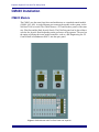
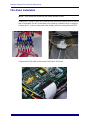
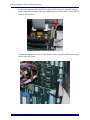
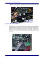
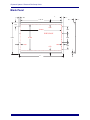
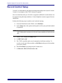
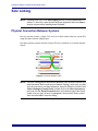
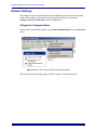
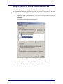
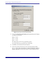
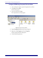
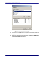
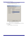
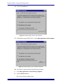
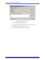
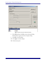
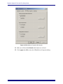
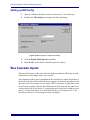
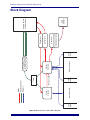
Euphonix System
System 5 Post and
Film Setup Guide
Document Revision: 1.2
Release Date: January 2006
Euphonix Inc.
220 Portage Ave.
Palo Alto, California 94306
Phone:
650-855-0400
Fax:
650-855-0410
Web:
http://www.euphonix.com
e-mail:
[email protected]
In the interest of continued product development, Euphonix reserves the right to make
improvements in this manual and the product it describes at any time, without notice or
obligation.
System 5, S-5, PatchNet, eMix, EuCon, R-1, Audio Deck, Studio Hub are trademarks of
Euphonix Inc.
©2006 Euphonix, Inc. All rights reserved worldwide. No part of this publication may be
reproduced, transmitted, transcribed, stored in a retrieval system, or translated into any
language in any form by any means without written permission of Euphonix, Inc.
Euphonix System 5 Post and Film Setup Guide
Table of Contents
CM403 Installation ..........................................................................................................................5
CM403 Module..............................................................................................................5
External Record Control ................................................................................................6
Film Panel Installation ...................................................................................................7
Joystick Panel Installation .............................................................................................9
Blank Panel ..................................................................................................................10
Record Control Setup.....................................................................................................................11
Solo Linking ..................................................................................................................................12
Physical Connection Between Systems .......................................................................12
Network Settings..........................................................................................................13
Setting up MOConfig...................................................................................................25
Bus Cascade Inputs ........................................................................................................................25
Block Diagram ...............................................................................................................................26
iii
Euphonix System 5 Post and Film Setup Guide
CM403 Installation
CM403 Module
The CM403 uses the same form factor and architecture as a standard control module
(CM401, 402, 408). A single Ethernet port connects the module to the system via the
100 BaseT EuCon switch. The CM403 houses a TFT and fits three panels of the same
size: Film Post and the Dual-Joystick Panels. The Film Post panel can be placed above
or below the Joystick Panel depending on the preference of the operator. The user has
the option of placing their own motion controller, such as a JSK Engineering Inc. P2
Control Head or Soundmaster ION™, into the spare panel.
Figure 1 CM403 Module with Film Post Panel and Joysticks
5
Euphonix System 5 Post and Film Setup Guide
ID selection
Up to four CM403 modules can be installed in a System 5 console. Set the ID switches
on the back panel of the module according to Table 1:
Table 1 CM403 ID Switch Settings
CM403 #
Frame ID
Module ID
Position # in
eMix
1
1H
13
1–29
2
1H
14
1–30
3
1H
15
1–31
4
1H
16
1–32
NOTE: In a dual-operator console, all CM403 modules are connected to the master
console, which is used for monitoring and record control.
External Record Control
The Euphonix EXT 25-pin connector on the rear panel of the CM403 accepts two
external closures:
Table 2
Function
Switch Input
+5 V
Record In
Pin 25
Pin 13
Record Out
Pin 11
Pin 13
The +5V output on the connector is internally protected by a 200 mA self-resetting fuse.
The active-high switch inputs are TTL-level inputs with 100 K pull-down resistors.
6
Euphonix System 5 Post and Film Setup Guide
Film Panel Installation
NOTE: Each instruction pertains to the picture beneath its text.
Connect the 5-V power cables (red) from the Film Panel to the header block on the bottom of the module. Be sure to maintain correct polarity (red/white stripe is negative).
Connect the 12-V power connection to the mating connector coming from the PSU.
Connect the PC104 cable to H26 on the Film Panels 386 board.
7
Euphonix System 5 Post and Film Setup Guide
Connect the opposite end of the PC104 cable to the PC104 card on the SBC (Single
Board Computer) mounted on the rear ventilation panel of the module. Secure the RF
choke as shown above.
Connect the Euphonix Ext cable (25-pin D-sub on the rear panel) to H103 on the upper
board of the Film Panel.
8
Euphonix System 5 Post and Film Setup Guide
Connect the TFT backlight cable to the connector on the upper board of the film panel.
Joystick Panel Installation
Connect the 5-V power cables (red) from the Joystick to the header block on the bottom
of the module. Be sure to maintain correct polarity (red/white stripe is negative). See
the photo in Film Panel Installation. Connect the serial cables from the 9-pin connectors
on the rear panel of the CM403 to the headers on the joystick PCBs. Attach two serial
cables between the external CM403 9-pin joystick ports and the adjacent CM408 9-pin
serial ports.
9
Euphonix System 5 Post and Film Setup Guide
Blank Panel
.480 X2
.285
.437
11.00 X2
1.150
.625
10.960
1.800
FREE SPACE
6.700
8.200
2.300
.500
.500
.875
11.960
1.800
.25
10
Euphonix System 5 Post and Film Setup Guide
Record Control Setup
Version 2.5 of eMix added record and track-arming functionality to the System 5 console.
Version 3.0x (or higher) of the TT007 software is required.
One record machine with up to 48 tracks is supported; additional record machines can
be supported using third-party hardware. Contact Euphonix customer support for more
information.
Perform the following steps to enable record- and track-arming:
1.
From the Main Panel on the CM401, select Machines.
2.
Select Setup and set the options on this panel to reflect your preferred method
of operation.
NOTE: Only the master console should be set to “Disarm on Stop” if this option is desired. Setting both consoles to do this will cause problems with tally information.
3.
On the TT007, display the Utility menu.
4.
Set REC Safe to Off.
5.
The TT007 normally sends record commands to the Master machine. To
record- or track-arm a Slave machine, set Re-Direct to the port of the machine
you wish to control.
6.
Enter Port Mode by pressing the port’s button twice.
7.
Set Record to Edit and Track Arm to On.
11
Euphonix System 5 Post and Film Setup Guide
Solo Linking
NOTE: Problems may occur if the Solo Linking service is running when eMix is installed. To avoid this, open the MOConfig.exe application and click Stop to
stop the service before installing newer software.
Physical Connection Between Systems
In a two-operator system, a single Cat5 cross-over cable connects the two system PCs
using the spare network adaptor ports.
In a three-operator system, the three System PCs are connected via a central ethernet
switch.
Figure 2 Crossover Network Cable
NOTE: The Solo Linking service requires the Windows user account to have a nonblank password. Before continuing to Network Settings, make sure your Windows account has a non-blank password: Open the Windows Control Panel
(Start->Settings->Control Panel), double-click on the User Accounts applet, and click the Reset Password button at the bottom-right of the dialog
(make sure your user account is highlighted in that window). Enter a password and press OK to close the dialog.
12
Euphonix System 5 Post and Film Setup Guide
Network Settings
The settings for the network identification and addressing are found in the Network
Connections window. Open the Network Connections window by choosing
Settings->Network Connections from the Start menu.
Change the Computer Name
In the Network Connections window, select Network Identification from the Advanced
menu.
Figure 3 Network Connections Window with Advanced Menu
The System Properties dialog opens with the Computer Name tab selected.
13
Euphonix System 5 Post and Film Setup Guide
Figure 4 Computer Name tab
1.
Click the Change button at the bottom-right.
A dialog appears requesting the new name.
2.
Type one the following names depending on the console being changed:
Master -
S5M
Slave1 -
S5S1
Slave2 -
S5S2
3.
Do not change the domain and workgroup settings; consult your network administrator for the proper settings for your network.
4.
Click OK on the renaming dialog.
A dialog appears warning that a restart is needed.
5.
Click OK.
6.
Click OK to close the System Properties dialog.
A dialog asks if you would like to restart the computer.
7.
Click No and do not restart the computer yet.
14
Euphonix System 5 Post and Film Setup Guide
Assign IP Address to Second Network Interface Card
Two network connections are displayed in the Network Connections window. One is
for your console’s modules and pilots (typically named EuCon) the other for the connection to your outside LAN.
1.
Right-click on the LAN connection (NOT the EuCon connection) and choose
Properties.
The Studio LAN Properties dialog opens.
Figure 5 Studio LAN Properties dialog
2.
Double-click Internet Protocol (TCP/IP) in the properties dialog.
The TCP/IP Properties dialog opens.
15
Euphonix System 5 Post and Film Setup Guide
Figure 6 Internet Protocol (TCP/IP) Properties dialog
3.
Click the Use The Following IP Address radio button and enter the IP address
according to the following:
Master - 10.0.0.1
Slave1 - 10.0.0.2
Slave2 - 10.0.0.3
The subnet mask is 255.255.255.0 for all three systems.
Leave the Default Gateway and DNS Server fields blank.
4.
Click OK to close the Internet Protocol Properties.
5.
Click on the Advanced tab at the top of the connection properties dialog.
Make sure Allow other network users to connect through this computer's
internet connection is checked in the Internet Connection Sharing section.
16
Euphonix System 5 Post and Film Setup Guide
Figure 7 Advanced tab of Studio LAN Properties dialog
6.
Press OK to close the connection properties dialog.
17
Euphonix System 5 Post and Film Setup Guide
Configure DCOM Using Component Services Editor
1.
After restarting the computer, open the Component Services Editor.
2.
Click Start and select Run.
The Run dialog appears.
3.
Type dcomcnfg and press Enter.
The Component Services Editor appears.
Figure 8 Component Services Editor
4.
Expand Component Services in the left pane (Figure 8).
5.
Right-click on My Computer and choose Properties.
The My Computer Properties dialog opens.
6.
Click the Default Properties tab.
18
Euphonix System 5 Post and Film Setup Guide
Figure 9 My Computer Properties-Default Properties tab
7.
Make sure Enable Distributed COM on this computer is checked, Default
Authentication Level is set to None, and Default Impersonation Level is set
to Impersonate.
8.
Then click Apply. (Do not click OK or you will close the System Properties
dialog).
9.
Now click the COM Security tab.
19
Euphonix System 5 Post and Film Setup Guide
Figure 10 My Computer Properties-COM Security tab
The tab has Edit Limits and Edit Defaults buttons for Access Permissions and
Launch & Activation Permissions. Each button opens a permissions setting dialog.
10. Click the Edit Limits and Edit Permissions buttons in turn. In each permissions dialog, select each user shown and click Allow for each permission.
You must add the following users or groups if they are not there:
Everyone, Interactive, Network, and System.
This must be done for every user listed in each of the four permissions dialogs.
An example of the Limits permissions for Launch & Activation is shown below.
20
Euphonix System 5 Post and Film Setup Guide
Figure 11 Launch Permissions dialog example
11. When finished, click Apply in the My Computer Properties dialog and the OK
to close it.
12. Back in the Component Services Editor window, expand My Computer, then
expand DCOM Config as shown below.
21
Euphonix System 5 Post and Film Setup Guide
Figure 12 Component Services-S5MultiServer
22
Euphonix System 5 Post and Film Setup Guide
13. Right-click on S5MultiServer, then choose Properties.
The S5MultiServer Properties dialog opens.
Figure 13 S5MultiServer Properties-General tab
14. In the General tab, make sure that Authentication Level is set to Default.
15. Click Apply.
Do NOT click OK or you will close the dialog.
23
Euphonix System 5 Post and Film Setup Guide
16. Click the Location tab.
Figure 14 Location Dialog - Run on this computer.
17. On the Master console (S5M -10.0.0.1), select Run application on this computer.
Figure 15 Location Dialog - Run on another computer.
18. On all Slave consoles perform the following procedure:
a.
Select Run application on the following computer.
b. Click the Browse button.
The Select Computer dialog opens.
24
Euphonix System 5 Post and Film Setup Guide
Figure 16 Select Computer dialog
c.
Click the Advanced button (bottom left).
The Select Computer dialog expands to the advanced search mode.
d. Click Find Now at the mid-right of the dialog.
All the computers available on the network appear.
25
Euphonix System 5 Post and Film Setup Guide
Figure 17 Select Computer-Advanced tab dialog
e.
Select S5M and then click OK to close the Advanced dialog.
S5M should now appear in the Select Computer dialog.
f.
Click OK to close that dialog.
19. Click Apply to retain the changes.
20. Click the Security tab.
26
Euphonix System 5 Post and Film Setup Guide
Figure 18 S5MultiServer Properties-Security tab
21. Make sure all three Use Default radio buttons are selected.
22. Click Apply then OK to close the S5MultiServer Properties dialog.
27
Euphonix System 5 Post and Film Setup Guide
Setting up MOConfig
1.
Open up a Windows Explorer window and locate the C:\emix directory.
2.
Double-click MOConfig.exe to display the following dialog:
Figure 19 Multi-Operator Configuration Dialog
3.
Click the Enable Multi Operator checkbox.
4.
Enter 10.0.0.1 for the Master Console System PC Address.
Bus Cascade Inputs
There are MADI ports on the front of the last (highest numbered) DF64 that are dedicated to Bus Cascade Inputs from a slave console.
The assignment of these port is dependant on the selected mixer model. Regardless of
the mixer model, the order in which the busses appear is: mix busses, group busses and
then aux busses. For example, a mixer model with 32 mix busses, 8 group busses and
16 aux busses, would use only the first MADI port for all 56 busses in the order listed.
A mixer model with 32 mix busses, 32 group busses and 16 aux busses would have mix
busses 1-32 and group busses 1-24 on the first MADI port. Group busses 25-32 followed by aux busses 1-16 would appear on the second port.
28
Film
Panel
Figure 20 Dual Operator System Block Diagram
29
Slave Console
Slave
Console
Network
Film
Panel
Bus Cascade
TT007
Machine Control
MADI
Master Console
Master
Console
Third-Party Machine
Control/Syncronizer
(Soundmaster, JSK)
Film
Panel
Monitor Controller
Converter
Converters
Converters
Main
Monitors
Audio Sources
and Recorders
Euphonix System 5 Post and Film Setup Guide
Block Diagram


![System 5 v5.3 Release Notes - akmedia.[bleep]digidesign.](http://vs1.manualzilla.com/store/data/007435483_1-869dfe736550f807afef326210c3426b-150x150.png)