1
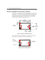
MT410 Controller for 4-Wire Resistive Touchscreens Reference Guide The information in this document is subject to change without notice. No part of this document may be reproduced or transmitted in any form or by any means, electronic or mechanical, for any purpose, without the express written permission of MicroTouch Systems, Inc. MicroTouch may have patents or pending patent applications, trademarks, copyrights, or other intellectual property rights covering subject matter in this document. The furnishing of this document does not give you license to these patents, trademarks, copyrights, or other intellectual property except as expressly provided in any written license agreement from MicroTouch. The information provided in this document is intended as a guide only. For the latest detailed engineering specifications, please contact your MicroTouch Systems Application Engineer. MicroTouch Systems is committed to continually improving product designs, as a result, product specifications may be subject to change without notification. © 2000-01 MicroTouch Systems, Inc. All rights reserved. Printed in the United States of America. Document Title: MT410 4-Wire Resistive Controller Reference Guide Document Number: 19-239, Version 2.1 MicroTouch, the MicroTouch logo, CleanScreen, ClearTek, KioskTouch, Microcal, ThruGlass, TouchPad, TouchPen, TouchWare, TouchTek, TruePoint, and ToughTouch are either registered trademarks or trademarks of MicroTouch Systems Incorporated in the United States and/or other countries. Microsoft, MS-DOS, Windows, and Windows NT are registered trademarks of Microsoft Corporation. Contents About This Manual MicroTouch Support Services ................................................................ 5 MicroTouch Technical Support ........................................................ 5 MicroTouch on the World Wide Web.............................................. 6 MicroTouch Corporate Headquarters and Worldwide Offices............... 7 Chapter 1 Integrating the MT410 Controller Overview of the MT410 Touchscreen Controller................................. 10 Mounting the MT410 Controller........................................................... 11 Connecting the Touchscreen Cable....................................................... 13 Establishing the Data Connection ......................................................... 14 Supplying Power to the Controller........................................................ 16 Using an Internal Power Supply (+5V) to JP2 ............................... 16 Using a Custom Serial Cable Design.............................................. 17 Using an External Wall-Mount Power Supply ............................... 17 Using a Keyboard Power Tap Cable .............................................. 17 Mounting the Touchscreen.................................................................... 18 Turning On Your System ...................................................................... 18 Status Light (LED) Diagnostics ............................................................ 19 What's Next? ......................................................................................... 21 Installing and Using TouchWare.................................................... 21 Calibrating the Touchscreen........................................................... 21 4 MT410 Controller Reference Guide Chapter 2 Communicating with the MT410 Controller Controller Default Settings.................................................................... 24 Communication Parameters ............................................................ 24 Data Format .................................................................................... 24 Operating Mode .............................................................................. 24 Communicating with the Controller...................................................... 25 Sending Commands to the Controller............................................. 25 Receiving Responses from the Controller ...................................... 26 Summary of Firmware Commands........................................................ 27 Firmware Commands ............................................................................ 29 Calibrate Extended ................................................................................ 30 Determining Target Areas .............................................................. 30 Guidelines for Calibrate Extended.................................................. 31 Calibrate Extended Procedure ........................................................ 32 Calibrate Raw ........................................................................................ 33 Controller Name .................................................................................... 35 Format Raw ........................................................................................... 36 Format Tablet ........................................................................................ 38 Mode Stream ......................................................................................... 40 Null Command ...................................................................................... 41 Output Identity ...................................................................................... 42 Reset ...................................................................................................... 43 Restore Defaults .................................................................................... 44 Unit Type............................................................................................... 45 Appendix A Index MT410 Controller Specifications About This Manual This reference manual, directed to developers of touchscreen systems, provides installation and configuration information for the MicroTouch MT410 4-wire resistive touchscreen controller. This document includes information on integrating the MT410 controller into your design, communicating with the controller, installing the TouchWare user interface software, and troubleshooting setup problems. It also includes a complete description of the firmware commands, a guide to interpreting status LED conditions, and a table of controller specifications. MicroTouch Support Services MicroTouch provides extensive support services through our technical support organization. You can contact technical support by telephone, fax, or electronic mail, or obtain updated information and drivers on the World Wide Web. MicroTouch Technical Support Technical Support by telephone is available: • 24 hours a day, Monday through Friday (excluding holidays) • 9:00 a.m. to 5:00 p.m. Eastern Standard Time, Saturday and Sunday (excluding holidays) The Technical Support Hot Line number is: 978-659-9200 6 MT410 Controller Reference Guide Whenever you contact Technical Support, please be ready to provide the following information: • Part numbers of your controller and sensor • Version number of your MicroTouch TouchWare • Make and model of your personal computer • Name and version number of your operating system • Type of mouse connected to your system • List of other peripherals connected to your system • List of application software installed on your system You can also submit a written description of the problem to MicroTouch Technical Support at any time by sending a fax or electronic mail. • Technical Support Fax: 978-659-9400 • Technical Support E-Mail: [email protected] MicroTouch on the World Wide Web You can download MicroTouch touchscreen software and drivers, obtain regularly updated technical information on MicroTouch products, or learn more about our company at the following web site: http://www.microtouch.com About This Manual MicroTouch Corporate Headquarters and Worldwide Offices United States MicroTouch Systems, Inc. 300 Griffin Brook Park Drive Methuen, MA 01844 United States Phone: 978-659-9000; Fax: 978-659-9100 Web Site: http://www.microtouch.com E-Mail: [email protected] Support Hot Line: 978-659-9200 Support Fax: 978-659-9400 Support E-Mail: [email protected] Australia MicroTouch Australia, PTA Ltd. 797 Springvale Road Mulgrave Victoria 3170 Australia Phone: +613 9582 4799 Web Site: http://www.microtouch.com.au E-Mail: [email protected] Support: [email protected] France MicroTouch Systems SARL Europarc de Créteil 19, rue Le Corbusier 94042 Créteil Cedex France Phone: +33 (1) 45 13 90 30 Email: [email protected] Germany MicroTouch Systems GmbH Schiess-Straße 55 40549 Düsseldorf Germany Phone: +49 (0) 211-5 99 07-0 Email: [email protected] Hong Kong MicroTouch Systems Ltd. Unit 1, 26/F, Westley Square 48 Hoi Yuen Road, Kwun Tong Kowloon, Hong Kong, SAR, PRC Phone: +852-2333-6138 Fax: +852-2333-6861 Email: [email protected] Italy MicroTouch Systems srl C.so Milano, 19 20052 Monza (MI) Italy Phone: +39 (0) 39-230-2230 Email: [email protected] Japan MicroTouch Systems K.K. Bellevue Mizonokuchi Building 3F 3-2-3, Hisamoto, Takatsu-ku Kawasaki-shi, Kanagawa 213 Japan Phone: +81 (44) 811-1191 Fax: +81 (44) 811-1138 Email: [email protected] Korea MicroTouch Systems, Inc. #402, 4th Floor, Nam-Kyung Building 769-6 Yeoksam-Dong, Kangnam-Gu Seoul, Korea Phone: +82 (2) 552-3198 Spain MicroTouch Systems SL Via Augusta 13-17, Oficina 704 08006 Barcelona Spain Phone: +34 93 415 62 85 Email: [email protected] Taiwan R.O.C. MicroTouch Systems, Inc. Taiwan 9-3 Floor, No. 33, Sec. 1, Minsheng Road Panchiao, Taipei County 22046 Taiwan, R.O.C. Phone: +886-2-2959-6647 Fax: +886-2-2959-6747 Email: [email protected] United Kingdom MicroTouch Systems, Ltd. 163 Milton Park Abingdon Oxon OX14 4SD England Phone: +44 (0) 1235-444400 Email: [email protected] 7 C H A P T E R 1 Integrating the MT410 Controller The MicroTouch MT410 controller offers an economical, high performance, 4-wire resistive solution for touch applications. Its compact design makes for easy integration into flat panel displays and mobile devices. The MT410 controller works with all the leading operating systems and is backed by the MicroTouch guarantee of worldwide support. This chapter covers the following MT410 controller specifications: • Mounting requirements • Power requirements and options • Cable connections • Data exchange • Status LED codes 10 MT410 Controller Reference Guide Overview of the MT410 Touchscreen Controller The MT410 is a compact controller with a standard RS-232 serial interface. It measures 1.3 x 2.435 inches with a total height profile of 0.4 inches from the thru hole pins on the trace side of the board to the top of the highest component on the opposite side. See Figure 1 for the board dimensions (profile not shown) and for mounting hole locations. 2.435" [61.85mm] 0.125" [3.18mm] JP3 0.125" [3.18mm] LED1 JP1 + JP2 1.300" 0.125" [33.02mm] [3.18mm] 0.125" [3.18mm] Figure 1 Dimensions and Hole Locations The MT410 has a touchscreen connector, a serial cable connector, and a power connector. See Figure 2 for connector identifications. 4-Wire Touchscreen Connector RS-232 Connector JP3 JP1 JP2 + Power LED1 Figure 2 Connector Identifications Chapter 1 Integrating the MT410 Controller 11 To properly integrate and test the MT410 controller, you need the following items: • A MicroTouch 4-wire resistive touchscreen, which is available in a variety of sizes, and the controller. • A method of establishing the serial data communication between the controller and your system. You can use the standard MicroTouch RS232 serial cable (P/N 7310101), or you can build your own cable. • A means of supplying power to the controller. There are several options available including a cable connection to the power connector (JP2) or supplying power through the serial cable. • A touchscreen driver with a 2–point calibration routine available to the end user. Note: You can use TouchWare, which includes the touchscreen device driver and utilities software. Mounting the MT410 Controller You can easily mount the MT410 controller using standard 4-40 machine screws and washers through the two existing mounting holes. All the components and the connectors are mounted on the top side of the PC board to reduce the overall profile and to minimize clearance requirements. Figure 3 shows the connector locations and identifies which of the mounting holes requires grounding. When you mount the MT410 controller, remember the following important rules: • Always mount the controller internally and orient the board so that the touchscreen flex cable is not twisted 180°. You can orient the components up or down, but if possible, mount the controller with the component side visible so you can monitor the status of the LED. • Route the touchscreen flex cable around the display and plug it into the touchscreen connector (JP3). • Ground the controller. Mount it to a metal chassis surface if possible. If you must mount it to a non-metal surface, be sure to attach a ground wire to the hole marked for grounding in Figure 3 as described in the last two paragraphs of this section. MT410 Controller Reference Guide 0.122" (4-40 screw grounding required) 0.400" [10.16mm] 0.430" 0.836" [10.92mm] [21.23mm] JP3 LED1 0.929" [23.60mm] JP1 JP2 + 12 0.200" [5.08mm] 0.122" (4-40 screw no-grounding required) 0.080" [2.03mm] Figure 3 Connector Locations and Hole Identifications • Maintain a clearance of at least 1/8 inch from the highest projection on the controller to the chassis. • Try to find a mounting area that is away from heat sources and EMI noise generators such as power supplies and backlight (or CRT) drive electronics. To avoid malfunctions or damage due to electrostatic discharge (ESD), make sure you properly ground the controller through the mounting hole shown in Figure 3. Ideally, you should mount the controller to a metal chassis surface using metal screws and metal standoffs. If you use plastic screws, or if you mount the controller to a non-metal surface, you must connect the mounting hole nearest the touchscreen connector (JP3) to a grounded location. See Figure 3. Be sure to route the wire to the nearest grounded location, and keep the wire dimensions as short and as thick as possible. MicroTouch recommends that you use braided ground cable with a flat lug crimped at both ends. Chapter 1 Integrating the MT410 Controller 13 Connecting the Touchscreen Cable The touchscreen connector (JP3) is a 4-pin AMP 103634-3 locking right angle male connector with pins on 0.1 inch centers. 4-Wire Touchscreen Connector JP3 LED1 JP1 JP2 + Figure 4 Touchscreen Connector The MT410 controller supports orienting the touchscreen with any of the four sides on the top. The controller firmware automatically determines the pinout configuration when you calibrate the touchscreen. This allows maximum flexibility in positioning the touchscreen tail. See Table 1 to determine which connector pin corresponds to which signed axis when the flex tail exits from the touchscreen at different locations. Table 1 Standard and Alternate Pinouts for MT410 Controllers (JP3) Pin # Standard Pinout (3:00 tail exit) Alternate Pinout 1 (6:00 tail exit) Alternate Pinout 2 (9:00 tail exit) Alternate Pinout 3 (12:00 exit) 1 Y- X- Y+ X+ 2 X+ Y- X- Y+ 3 Y+ X+ Y- X- 4 X- Y+ X+ Y- 14 MT410 Controller Reference Guide Establishing the Data Connection The MT410 controller requires that an RS-232 serial communication cable be attached to connector JP1. RS-232 Cable Connector JP3 LED1 JP1 JP2 + Figure 5 Data Connector You can use a standard MicroTouch RS-232 cable (P/N 7310101). You may need a 9-pin to 25-pin adapter if the only available communication (COM) port on your PC has 25 pins. One end of this cable plugs into the RS-232 connector (JP1) on the MT410 controller (Figure 5). The other end, which has a 9-pin D connector, plugs into a COM port on your PC, directly or through the adapter. Table 2 describes the interconnections for the MicroTouch RS-232 cable. For OEM designs, you can build your own cable using a 7-pin Molex connector (51004-0700) to mate to the JP1 connector, and design your own connector or hard-wired configuration at the other end. As an option, MicroTouch can supply a controller with the RS-232 transceiver removed and bypassed to allow a direct serial 5V logic interface. Chapter 1 Integrating the MT410 Controller Table 2 COM Cable for MT410 Controller (JP1) Wire PC Side (9-Pin D) Controller Side (7-Pin Molex) Pin RS-232 Assigned Jumpered to: Color Pin 1 Data Carrier Detect (DCD) 4 and 6 DTR and DSR None 2 Receive Data (RXD) Brown 2 Transmit Data (TXD) 3 Transmit Data (TXD) Red 3 Receive Data (RXD) 4 Data Terminal Ready (DTR) None 5 Signal Ground Blue 5 6 Data Set Ready (DSR) None 7 Request to Send (RTS) Black 1 Request to Send (RTS) 8 Clear to Send (CTS) Green 4 Clear to Send (CTS) Sleeve White 6 DC power jack (+5 VDC) Pin 7 Cable shield connected to ground. DC power jack ground Shell 7 Chassis (earth) ground 1 and 6 DCD and DSR 1 and 4 DCD and DSR Description Power supply ground 15 16 MT410 Controller Reference Guide Supplying Power to the Controller You must supply the MT410 controller with power. You can use internal power (that is, tap power from inside the monitor or PC) or external power. Note: The power source must deliver 70 mA typical, with a maximum ripple and noise of 50 mV peak-to-peak. Power should be limited to less than one amp. A 1 amp fuse or current limited power regulator is recommended. Power Connector JP3 LED1 JP1 JP2 + Figure 6 Power Connector You can supply power to the MT410 controller using any of the following methods: • Internal power into JP2 using +5 volts DC at JP2, pin 1 and power supply ground at JP2, pin 2 • Internal power through a custom serial cable configuration • External power (+5 volts DC) from a wall-mount power supply • External power (+5 volts DC) from a keyboard power tap cable Caution: Do not supply both internal power and external power to the controller. Power from two sources could damage one or both of the power supplies. Using an Internal Power Supply (+5V) to JP2 You can power the MT410 at JP2 using a +5 volt DC power source within the system. Chapter 1 Integrating the MT410 Controller ! 17 To provide power directly to the controller using JP2: 1. Obtain a locking, mating connector for JP2 (Molex housing 22-01-3027 with 08-50-0114 contacts). 2. Attach power and ground to the connector (Pin 1: +5V , Pin 2: Ground). The connector is keyed. Pin 1 has continuity to the trace marked + on the board. 3. Insert locking connector into JP2. Using a Custom Serial Cable Design ! When creating a custom serial cable connection (see Establishing the Data Connection), you can provide power to the controller through the mating Molex connector: 1. Obtain a 7-pin Molex connector 51004-0700. 2. Attach power and ground to the connector, (Pin 6: +5V, Pin 7: Ground). Using an External Wall-Mount Power Supply If you are using a standard MicroTouch RS-232 serial cable (P/N 7310101), you can use either a 120 volt wall-mount power supply (P/N 19-408) or a 220 volt wall-mount power supply (P/N 19-409). ! To connect an external wall-mount power supply: 1. Remove the plastic plug covering the power jack of the 9-pin D connector on the serial cable. 2. Connect a DC power plug to the power jack built into the 9-pin D connector. 3. Plug the power supply into a grounded outlet. The power plug supplies both +5V and ground. Using a Keyboard Power Tap Cable If you are using a standard MicroTouch RS-232 serial cable, you can use either a 5-pin IBM AT compatible keyboard power tap cable (MicroTouch P/N 19-356) or a 6-pin IBM PS/2 compatible keyboard power tap cable (P/N 19-357). 18 MT410 Controller Reference Guide ! To connect a keyboard power tap cable: 1. Disconnect the keyboard cable from the back of your computer. 2. Plug the keyboard cable into the power tap cable. 3. Plug the power tap cable into the keyboard socket on the back of your computer. 4. Remove the plastic plug covering the power jack of the 9-pin D connector on the serial cable. 5. Connect the DC plug from the power tap cable to the jack built into the 9-pin D connector. Mounting the Touchscreen There are several methods for mounting the touchscreen depending on your application (CRT displays, LCD modules, flat panel displays, each in a variety of sizes). If you need instructions or recommendations from MicroTouch on how to incorporate a touchscreen into your OEM design, you can order the publication Touchscreen Kits Installation Guide (Document Number 19-215). Turning On Your System Before you turn on your custom system, ensure that all cables are connected properly and that the controller is properly mounted. Be sure to tighten all cable connector screws. ! To start up your system: 1. Turn on your monitor and computer. 2. Adjust the contrast and brightness to suit your personal preference and working environment. 3. Adjust the horizontal and vertical position controls on the monitor to center the image on the screen. The MT410 controller has a light emitting diode (LED) on the component side of the board that indicates the status of the touchscreen unit. Chapter 1 Integrating the MT410 Controller 19 If it was necessary for you to mount the controller component side down, you can determine the status of the LED from its reflected light off the mounting surface. Status Light (LED) Diagnostics MicroTouch controllers are highly reliable units, however there may be occasions when the controller does not perform exactly as you expect. The MT410 controller provides diagnostic feedback with the LED shown in Figure 7. When you power-up the unit, the LED is on until the controller start-up sequence is completed. Following start-up, the LED goes out and remains out as long as you do not touch the sensor. When you touch the sensor, the LED goes on. A flashing (or blinking) LED during power-up indicates the controller’s power-on self-test failed. Refer to Table 3 for a description of each error code. LED JP3 LED1 JP1 JP2 + Figure 7 Diagnostic LED 20 MT410 Controller Reference Guide Table 3 LED Diagnostic Codes for MT410 Controller LED Flashes (/10 sec.) Self Test Bit (Unit Type Command) 2 1 ROM error. Firmware checksum verification error. 3 Block 1 EEPROM error. The operating parameters in the controller EEPROM are invalid. Using defaults. 7 Block2 EEPROM error. The linearization data in the controller EEPROM is invalid. 4 8 Error Description Note: Some errors are non-recoverable, meaning that normal touchscreen operation cannot occur. Recoverable errors cause the controller to revert to default values. Chapter 1 Integrating the MT410 Controller 21 What's Next? You have successfully installed the MT410 controller and connected the touchscreen to your computer. You are now ready to complete the following tasks: • Install TouchWare or equivalent software for your touchscreen • Use the software to calibrate the touchscreen Installing and Using TouchWare TouchWare includes the software driver that lets your touchscreen work with your computer. MicroTouch has touchscreen drivers for many operating systems, including Windows 3.1x, Windows 95, Windows 98, Windows NT, MS-DOS, and OS-2. Be sure to install the touchscreen software for the operating system you are using. TouchWare also includes a control panel for setting user touchscreen preferences and diagnostic utilities for isolating problems. For more information on installing and using the touchscreen control panel, refer to the TouchWare for Windows User’s Guide. Calibrating the Touchscreen Calibration aligns the touchscreen with the underlying video by defining the dimensions of the image area on the touchscreen, determining the edges of the screen’s image, and locating the center of the touchscreen. You must calibrate the touchscreen and test the calibration to ensure its successful operation. See the TouchWare for Windows User’s Guide for instructions on calibrating your touchscreen. C H A P T E R 2 Communicating with the MT410 Controller This chapter discusses the fundamentals of communicating with the MT410 controller. The firmware commands, which are usually issued by a driver or utility program on the host system, control the operation of the touchscreen controller, however developers can enter these commands directly. This chapter • Describes the controller default settings • Lists the recommended firmware commands for current development • Describes how to use each of these commands The description of each command includes the command syntax, the default value, how the command works, and the expected response from the controller. 24 MT410 Controller Reference Guide Controller Default Settings This section provides detailed information on the default settings for the MT410 chipset controller. Communication Parameters The default operation of the MT410 controller is N, 8, 1 (no parity, 8 data bits, and 1 stop bit) at 9600 baud. Data Format Data format refers to the type of packet the controller uses to send the X/Y touch coordinates to the host system. Format Tablet is the default 8–bit format for the MT410 controller. Since the processor is an 8–bit machine, the data needs to arrive in 8 data bit format. Format Tablet is also the standard for MicroTouch product development and is the format used by all current touchscreen drivers written by MicroTouch. MicroTouch uses Format Tablet for the following reasons: • Format Tablet uses only 5 bytes per point and provides the most rapid response time to a touch. • Format Tablet is the most efficient and most compact data format It sends approximately 167 packets per second at 9600 baud. • Format Tablet includes a status byte. The status byte contains information on whether the X/Y coordinate is generated from a touchdown, a touch continuation (the finger resting on the screen), or a touch liftoff. • Format Tablet is supported by all MicroTouch touchscreen controllers. Operating Mode The operating mode specifies how the controller sends the X/Y touch coordinates (input data packet) to the host system. Chapter 2 Communicating with the MT410 Controller 25 Mode Stream is the default operating mode for the MT410 controller and the mode that MicroTouch recommends you use. In Mode Stream, the controller sends a continuous stream of data packets when the touchscreen is touched. The controller sends the data as long as the touch continues on the screen. Because Mode Stream sends touch data continually, it is the most versatile mode enabling program filtering at any touch event. It also provides the best response time and overall feel. If you use a processor other than the one recommended in this document package, MicroTouch software requires that the touchscreen system generate a host system interrupt as each byte or packet in the data stream arrives so that each touch event can be individually identified. Because touchdown and liftoff events are specially coded, your software always knows exactly what the user is doing, provided that the interrupts are sent as recommended. This enables instant feedback capability and prevents data loss. Communicating with the Controller This section explains how to send firmware commands to the MT410 chipset controller and how to interpret the controller’s responses. The host sends commands to the controller on the processor’s Receive Data (RXD) line as a serial data stream. The controller responds to the host system on the processor’s Transmit Data (TXD) line, also as a serial data stream. Sending Commands to the Controller When you send a command to the controller, you must use the correct command format. The general format of a command is: <Header>Command<Terminator> Note: The following descriptions of header, command, and terminator, use MicroTouch’s terminal emulator key sequences. You may need to enter the sequence in a different format, depending on your emulator, however MicroTouch recommends using TouchWare or other MicroTouch utilities operating in Terminal Mode. 26 MT410 Controller Reference Guide The header is the first character in the command string and is the ASCII start–of–header control character SOH (01 hexadecimal). To start the command sequence, send the SOH character. Most terminal emulators use the key sequence <Ctrl A> (^A). Using Microcal, TouchWare, or most IBM compatible terminal emulators, SOH is displayed as ☺. Since the controller echoes the character it receives, typing <Ctrl A> returns a ☺ to the screen. The command, which always follows the header, consists of ASCII uppercase letters and numbers. The terminator is the last character in the command string and is the ASCII carriage return control character CR (0D hexadecimal). To end the command sequence, use <Enter> or the key sequence <Ctrl M> (^M). This chapter lists each command as a string of ASCII characters consisting of a header, the command, and a terminator as follows: <SOH>Command<CR> Receiving Responses from the Controller After executing a command, the controller returns a response or acknowledgment to the host system. Each controller response consists of a header, the command response, and a terminator in the following format: <Header>Command Response<Terminator> The header is the first character in the response string and is the ASCII start–of–header control character SOH (01 hexadecimal). The character returned with Microcal, TouchWare, or most terminal emulators is ☺. The response, which always follows the header, is a range of ASCII characters depending on the type of command received. The terminator is the last character of each response string and is an ASCII carriage return CR (0D hexadecimal). An ASCII CR moves the terminal emulator cursor to the next line. Responses can be in many forms. For example, one standard response is <SOH>0<CR> (ASCII character ‘zero’ or 30 hexadecimal). This response indicates a successful command completion for most commands, while it indicates a failed completion for other commands. See the Firmware reference section for a description of what the response indicates for each particular command. Chapter 2 Communicating with the MT410 Controller 27 Another standard response is <SOH>1<CR> (ASCII character ‘one’ or 31 hexadecimal). For most commands, this response indicates that the command failed. The controller received an invalid that it could not execute. Some possible reasons for the failure include: • The command was not formatted correctly. • The system parameters were not set up to allow command execution. • The controller does not support the command. In this chapter, responses are shown as a string of ASCII characters consisting of a header, the response, and a terminator as follows: <SOH>Response<CR> Summary of Firmware Commands Developers may use this information when writing touch applications, developing a custom driver or touch configuration, or testing their touch systems. Developers can use firmware commands to initialize the controller, select operating modes, specify data formats, and execute diagnostic functions. Most touchscreen users do not have to use firmware commands to use their touch systems. They can make changes using TouchWare or Microcal, the software delivered with the touchscreen. For example, end users can use TouchWare to calibrate the touchscreen or to determine the controller type and firmware version without having to enter firmware commands. Caution: This document is directed to developers and assumes you are familiar with firmware commands and how to use them. Executing some commands will alter the performance of your touchscreen or render it inoperable. To optimize the performance of the MT410 touchscreen controller and to simplify the development of custom drivers, MicroTouch recommends you use the commands listed in this document. Table 4 provides a summary of the firmware commands which are covered in more detail later in this document. 28 MT410 Controller Reference Guide Table 4 Summary of Firmware Commands Command Name ASCII Code Description Calibrate Extended CX Initiates an interactive, two–point calibration. Calibrate Raw CR Collects the raw X and Y coordinates prior to normal scaling, linearization, and filtering process. Controller Name NM Returns a null terminated character string defining the name of the controller. Format Raw FR Returns the signal level (amount of touch) of each of the four touchscreen bus bars in digital format. Format Tablet FT Outputs the X/Y touch coordinate data in a five–byte packet. Mode Stream MS Sends a continuous stream of X/Y coordinate data when you touch the screen. Null Command Z Queries the controller and waits for a response. Output Identity OI Identifies the controller type and the firmware version. Reset R Initializes the hardware and the firmware, causes the controller to stop sending data, and recalculates the environmental conditions. Restore Defaults RD Returns the controller to the factory default operating parameters. Unit Type UT Identifies the type of touchscreen controller connected to your system. Chapter 2 Communicating with the MT410 Controller Firmware Commands This section covers the command format for each firmware command and the range of responses you can expect to receive from the controller. 29 30 MT410 Controller Reference Guide Calibrate Extended Syntax: <SOH>CX<CR> Description: Initiates an interactive, two–point calibration. During the calibration process, you define the active area of the touchscreen by mapping locations to an absolute X/Y coordinate system. You touch two target areas on the screen. Touching the target areas sends the X/Y coordinates for those touch points to the controller. The controller calculates all other touch points based on these two points. The Calibrate Extended command sets the calibration targets (points) inward from the corner of the video image. Setting the targets inward makes the calibration process easier and more accurate. Determining Target Areas The default calibration targets (points) are located 12.5% (1/8) inward from the corner of the video image. For example, suppose the display resolution of your monitor is 1024 x 768. The Calibrate Extended command calculates the amount to move inward as follows: • Amount to move inward in the X direction: 1024 x 1/8 = 128 • Amount to move inward in the Y direction: 768 x 1/8 = 96 The Calibrate Extended command then positions the first calibration target inward from the lower left corner (0,767) and the second calibration target inward from the upper right corner (1023,0). The following illustration shows how the calibration targets are calculated. You can adjust the default calibration points using the Set Parameter Block command. For more information, contact MicroTouch. Chapter 2 Communicating with the MT410 Controller 31 (1023, 0) (0, 0) (560, (895, 96) 420) Upper Right Calibration Target X = 1023 – (1024 x 1/8) = 1023 – 128 = 895 Y = 0 + (768 x 1/8) = 0 + 96 = 96 (128, (80, 60) 671) (0, 767) Lower Left Calibration Target X = 0 + (1024 x 1/8) = 0 + 128 = 128 Y = 767 - (768 x 1/8) = 767 - 96 = 671 Note: The example in this discussion is in video terms, with the origin (0, 0) in the upper left corner of the screen. Examples from the controller’s perspective, however, place the origin at the lower left corner of the screen. Guidelines for Calibrate Extended Here are several guidelines for using the Calibrate Extended command: • The controller uses the data immediately before liftoff to register a calibration touch. Therefore, users can touch the screen, move their finger to the target, hold for one second, and then lift off their finger. Instructing users to touch this way results in a more accurate calibration. • The controller stores the data in non–volatile memory (NoVRAM). Therefore, you do not have to calibrate the screen each time you power on the system. You should, however, recalibrate the touchscreen any time the video display changes or gets repositioned. • You can cancel a calibration at any time by issuing a Reset command. 32 MT410 Controller Reference Guide Calibrate Extended Procedure To use the CX command: 1. Enter the Calibrate Extended (CX) command. The controller sends an acknowledgment of <SOH>0<CR>. 2. Touch the screen at a lower left target, which is located 12.5% (1/8) in from the corner of the video image. The controller returns an acknowledgment of <SOH>1<CR>. This is a positive response. If you receive a negative response, try touching the screen again. 3. Touch the screen at an upper right target, which is located 12.5% (1/8) in from the corner of the video image. The controller returns an acknowledgment of <SOH>1<CR>. If you receive a negative response, try touching the screen again. Touching the two valid calibration points results in a successful calibration. If either calibration point is invalid, the calibration fails. The MT410 controller restores the factory default calibration if the Calibrate Extended routine fails. Response: <SOH>1<CR> Positive response. Indicates that the controller received a valid touch coordinate (point) when the target was touched. Two valid touch points indicate a successful calibration. <SOH>0<CR> Negative response. Indicates that the touch point is out of range of the expected target area. If you receive a negative response, try touching the target area again. <SOH>2<CR> Indicates that the user did not touch the target long enough to provide an accurate calibration point. Chapter 2 Communicating with the MT410 Controller 33 Calibrate Raw Syntax: <SOH>CR<CR> Description: Allows the collection of raw (signed) X and Y coordinates prior to the normal scaling, linearization, and filtering processes. The controller sends the coordinates whenever a touch is detected and continues to send a stream of data as long as a finger remains in contact with the touchscreen. The Calibrate Raw data is a 5–byte packet that includes 1 status byte and 4 bytes of binary X/Y coordinate data. Each X/Y coordinate includes 10 binary bits and 1 sign bit. The 10 bits represent coordinates within a range of –1024 to +1023. To use the Calibrate Raw command, the controller and host system must be in an 8–bit data communication mode. The Calibrate Raw command returns a negative response if the controller is not using an 8–bit communication mode. To end Calibrate Raw mode, issue a Reset command. MicroTouch uses the Calibrate Raw command during manufacturing and testing, and recommends you use this command for diagnostics when you want raw data. Use the Calibrate Extended command for standard interactive, two–point calibration. Response: <SOH>0<CR> Positive response. After the controller is in Calibrate Raw mode, touching the screen causes the controller to return a response in the following format: SXxYy where: S = Status byte; first byte of data. Refer to Table 5. Xx = X (horizontal) coordinate data; second and third bytes of data Yy = Y (vertical) coordinate data; fourth and fifth bytes of data. 34 MT410 Controller Reference Guide MSB* Bits Data Sequence 7 6 S - Byte 1 1 S6 5 4 LSB* 3 2 1 0 Reserved X - Byte 2 0 X3 X2 X1 X0 x - Byte 3 0 Xs** X9 X8 X7 Y - Byte 4 0 Y3 Y2 Y1 Y0 y - Byte 5 0 Ys** Y9 Y8 Y7 Reserved X6 X5 X4 Reserved Y6 Y5 Y4 * MSB = Most Significant Bit, LSB = Least Significant Bit ** s = sign bit Table 5 describes the meaning of the bits in the status byte (Byte 1). Table 5 Calibrate Raw Status Bits Bit Description Values S0 – S5 Reserved — S6 Proximity (touch state) 1= Touchscreen is being touched (a touchdown or a continued touch). 0= Touchscreen is not being touched (a touch liftoff or inactive). When the proximity bit changes from 1 to 0 (touch liftoff), the controller outputs one final set of X/Y coordinate data with the bit equal to 0 and the X/Y coordinate data equal to the last touch point. S7 Packet synchronization Always 1. Chapter 2 Communicating with the MT410 Controller 35 Controller Name Syntax: <SOH>NM<CR> Description: Returns a character string of any length, terminated by a null character. The character string can be used to display the name of the controller. Response: xxxxxx...<nul> 36 MT410 Controller Reference Guide Format Raw Syntax: <SOH>FR<CR> Description: Returns uncorrected X and Y coordinates. The returned values are not corrected for offset and stray values, however you can obtain the offset and stray values using the Get Parameter Block command. For more information, refer to the description of the Get Parameter Block command later in this chapter. Format Raw data is a 5–byte packet that includes 1 status byte and 4 bytes of binary position data. The data format for the packet is fixed in order to provide the most efficient transfer of data. The first byte of each packet always has its high bit (Bit 7) set to enable packet. Each position value is 11 bits, which are delivered in 2 bytes, and has a range of 0 to 2047. To use the Format Raw command, the controller and host system must be in an 8–bit data communication mode. The Format Raw command returns a negative response if the controller is not using an 8–bit communication mode. To terminate Format Raw, issue a Reset command. The controller may return several bytes of data between the time you issue a Reset command and the controller receives it. You can either scan the data stream for the Reset acknowledgment, or you can ignore the response to the first Reset command and then issue a second Reset after approximately 10 seconds has passed. You may use the Format Raw for diagnostics, but use Format Tablet for standard touchscreen operation. Response: <SOH>0<CR> Positive response. After the controller is in Format Raw mode, the controller returns a response in the following format: <5–byte–packet><5–byte–packet>...<5–byte–packet>... Chapter 2 Communicating with the MT410 Controller 37 SXxYy where: S = Status byte; first byte of data. Refer to Table 5. Xx = X (horizontal) coordinate data; second and third bytes of data Yy = Y (vertical) coordinate data; fourth and fifth bytes of data. MSB* Bits 5 4 LSB* Data Sequence 7 6 3 2 S - Byte 1 1 S6 X - Byte 2 0 X3 X2 X1 X0 x - Byte 3 0 Xs** X9 X8 X7 Y - Byte 4 0 Y3 Y2 Y1 Y0 y - Byte 5 0 Ys** Y9 Y8 Y7 1 0 Reserved * MSB = Most Significant Bit, LSB = Least Significant Bit ** s = sign bit Reserved X6 X5 X4 Reserved Y6 Y5 Y4 38 MT410 Controller Reference Guide Format Tablet Syntax: <SOH>FT<CR> Description: Outputs the calibrated X/Y touch coordinate data in a 5–byte packet. The packet includes 1 status byte and 4 bytes of binary X/Y coordinate data. X and Y coordinates are sent out as 14 binary bits providing a range of 0 to 16,383, however the low order bits (X3 – X0 and Y3 – Y0) are not used. To use Format Tablet, the controller and host system must be in an 8–bit data communication mode. The Format Tablet command returns a negative response if the controller is not using an 8–bit communication mode. Format Tablet is the most efficient data format. It sends approximately 167 packets per second at 9600 baud. It also contains touchdown and liftoff information. Format Tablet is the standard for MicroTouch product development. Response: <SOH>0<CR> Positive response. After the controller is in Format Tablet mode, touching the screen causes the controller to return a response in the following format: SXxYy S = Status byte; first byte of data. Refer to Table 6. Xx = X (horizontal) coordinate data; second and third bytes of data Yy = Y (vertical) coordinate data; fourth and fifth bytes of data. MSB* Bits 5 4 LSB* Data Sequence 7 6 3 2 1 0 S - Byte 1 1 S6 X - Byte 2 0 X6 X5 X4 X3 X2 X1 X0 x - Byte 3 0 X13 X12 X11 X10 X9 X8 X7 Y - Byte 4 0 Y6 Y5 Y4 Y3 Y2 Y1 Y0 y - Byte 5 0 Y13 Y12 Y11 Y10 Y9 Y8 Y7 Reserved * MSB = Most Significant Bit, LSB = Least Significant Bit Chapter 2 Communicating with the MT410 Controller 39 Table 6 defines the status bits (Byte 1) for the Format Tablet data. Table 6 Format Tablet Status Bits Bit Description Values S0 – S5 Reserved — S6 Proximity (touch state) 1= 0= Touchscreen is being touched (a touchdown or a continued touch). Touchscreen is not being touched (a touch liftoff or inactive). When the proximity bit changes from 1 to 0 (touch liftoff), the controller outputs one final set of X/Y coordinate data with the bit equal to 0 and the X/Y coordinate data equal to the last touch point. S7 Packet synchronization Always 1. 40 MT410 Controller Reference Guide Mode Stream Syntax: <SOH>MS<CR> Description: Sends a continuous stream of X/Y coordinate data when you touch the screen. The controller continues to send data as long as you touch the screen. The controller sends the data even if the touch is stationary and unchanging. The format of the coordinate data depends on the last format command received by the controller. Note: Format Raw automatically uses Mode Stream to send X/Y coordinate data. Response: <SOH>0<CR> Positive response. Chapter 2 Communicating with the MT410 Controller Null Command Syntax: <SOH>Z<CR> Description: Queries the controller and waits for a response. Use Z to determine that you are communicating with the controller or to make sure that a utility is communicating with the controller. Using this command does not affect the controller’s current operating parameters. Response: <SOH>0<CR> Positive response. 41 42 MT410 Controller Reference Guide Output Identity Syntax: <SOH>OI<CR> Description: Returns a 6–character identifier, which describes the controller type and the firmware version number. Response: <SOH>CcXxxx<CR> where: Cc = Two ASCII characters that describe the type of MicroTouch controller. MT = Small format resistive serial controllers and chipsets Xxxx = Four ASCII characters that indicate the firmware version number in decimal format. The first two characters represent the version number; the last two characters represent the revision level. For example, 0640 means Version 6, Revision 4 (that is, 6.4). Chapter 2 Communicating with the MT410 Controller 43 Reset Syntax: <SOH>R<CR> Description: Initializes the hardware and the firmware, causes the controller to stop sending data, and recalculates the environmental conditions (for example, stray and offset values). The Reset command also cancels the Format Raw and Calibrate Raw commands and returns the controller to normal operation. MicroTouch recommends that the host system issue a Reset command whenever the host system is powered on and is attempting to establish communication with the controller. The amount of time needed to execute a Reset command ranges from 225 milliseconds to 800 milliseconds. Therefore, the application program should wait and be sure it receives the command response before issuing another command to the controller following the reset. Response: <SOH>0<CR> Positive response. 44 MT410 Controller Reference Guide Restore Defaults Syntax: <SOH>RD<CR> Description: Returns to the factory default operating parameters. The Restore Defaults command copies the MicroTouch factory default parameters from ROM to the non–volatile memory (NoVRAM) and then executes a Reset command. Table 7 lists the factory defaults for the MT410 controller. The Restore Defaults command is useful in situations where inadvertent commands to the controller have rendered the touchscreen inoperative. Table 7 MT410 Factory Default Settings Operating Parameter Default Baud Rate 9600 Serial Communication Settings N, 8, 1 Data Format Format Tablet Operating Mode Mode Stream Return to Factory Calibration Yes The Restore Defaults command requires approximately 75 to 100 milliseconds, plus the execution time of the Reset command (225 to 800 milliseconds). Therefore, the application program should wait and be sure it receives the command response before issuing another command to the controller. Notes: After you issue a Restore Defaults command, calibrate your touchscreen using the Calibrate Extended command. Restore Defaults does not reset screen linearization data that is set with the Calibrate Extended (CX) command. Response: <SOH>0<CR> Positive response. Chapter 2 Communicating with the MT410 Controller 45 Unit Type Syntax: <SOH>UT<CR> Description: Responds with an 8–character identity string. This string identifies the type of controller currently attached to the system, lists the features supported by the controller, and outputs the status of the controller hardware (a self–test code). The identification code for the MT410 controller is MTR***00. Response: Returns an identification code up to 8 ASCII characters in the following format: <SOH>TtFfffSs<CR> where: Tt = Two ASCII characters that identify the controller type. TP = TouchPen series of controllers QM = Serial/SMT3 series of controllers MT = Small format resistive serial controllers and chipsets Ffff = Four ASCII characters that indicate the features supported by the controller. R = Indicates a resistive controller V = Indicates Excalibur and Serial/SMT3V series controllers *** = Indicates no additional features configured Ss = Two ASCII characters that provide status information about the controller hardware. The two characters represent one byte. Each character is in the range 0 to 9 and A to F. Table 8 defines the meaning of each bit in the status byte. Each bit can be set to 1 or 0, where: 1 = Error 0 = No error 00 = No diagnostic errors (normal response) 46 MT410 Controller Reference Guide Table 8 Bit Definition for the Unit Type Command Bit Controller Status 1 ROM error. Firmware checksum verification error. 3 Block 1 NoVRAM error. The operating parameters in the controller NoVRAM are invalid. Using defaults. 7 Block 2 NoVRAM error. The data in the controller NoVRAM is invalid. A P P E N D I X A MT410 Controller Specifications MT410 Controller: Programmable CMOS, small format-size controller Circuit Board Dimensions: 1.3 in. x 2.4 in. (33 mm x 61 mm) Power Requirements: +5 VDC (70 mA typical), 50 mV peakto-peak maximum ripple and noise Operating Temperature: 0 to 60 degrees C Storage Temperature: -40 to +85 degrees C Relative Humidity: 90% at 60 degrees C Optional RS-232 Cable: 8' shielded cable with 9-pin D connector for serial port; 9-pin to 25-pin adapter available Output Port: Bi-directional asynchronous RS-232 serial communication Port Parameters: No parity, 8 data bits, 1 stop bit, 9600 baud (N, 8, 1, 9600) Electrostatic Protection: ±8KV air and ±4KV contact discharge to screen (per IEC 801-2) Regulatory Approvals: UL, FCC-B, and CE compliant Index A adapter, 9-pin to 25-pin 14 dimensions 21 driver 11, 21, 23 E B bits data 46 parity 46 electrostatic discharge 12 error 19 errors 20 C F calibration definition 21 clearance 11, 12 connecting the touchscreen cable 13 connectors JP1 14 JP2 16, 17 Molex 17 serial cable 17, 18 corporate headquarters 7 flat panel displays 9, 18 D data connection 14 diagnostic codes, LED 20 G ground 11, 12, 15, 16, 17 grounding 11 H headquarters, corporate 7 help phone support 5 world wide web 6 50 MT410 Controller Reference Guide I P Internet address, MicroTouch 6 phone support 5 pins 14 power requirements 46 power, supplying external 17 internal 16, 17 profile 10, 11 J JP1 connector 14 JP2 connector 16, 17 K keyboard power tap 16, 17 R RS-232 10, 11, 14, 15, 17, 46 L LCD modules 18 LED 18, 19 M MicroTouch Internet address 6 mounting holes 11, 12 MT410 controller LED 18 overview 9 power connector 16 serial data connector 14 specifications 46 S screws 11, 12, 18 specifications 46 standoffs 12 supplying power 16 support, technical 5 T technical support 5 telephone support 5 temperature 46 TouchWare 6, 21 O W orientation 11 wall-mount power supply 17 World Wide Web site 6 worldwide offices 7