1
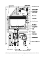
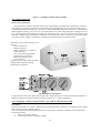
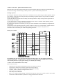
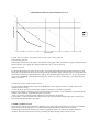
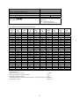
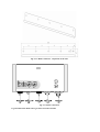
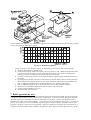
VIADRUS CLEO WALL BOILER OPERATION AND INSTALLATION MANUAL Dear customer We thank you that you have bought the VIADRUS CLEO boiler thus having shown your confidence in ŽDB a.s.Bohumín, VIADRUS Heating technology Enterprise. For you to get used to a correct way of handling your new product from the beginning please read at first this manual for its usage . Please follow the information stated in this manual and especially those regarding the prescribed annual controls to be done by an authorized specialised firm , whereby a long-time and trouble-free boiler operation will be guaranteed to both your and our satisfaction. CLEO wall boiler was approved to be operated in the Czech Republic by: Engineering Testing Institute, State Testing Laboratory no. 202, Brno on the basis of Certificate E-37-00098-03, E-37-00105-03 Warm-water natural gas boilers, VIADRUS CLEO K, and Certificate E-37-00106-03, E-37-00107-03 Warm-water natural gas boilers, VIADRUS CLEO T odnutí 2 TABLE OF CONTENTS 1. Manufactured boiler variants............................................................................................................... 3 2. Boiler usage and advantages .............................................................................................................. 4 3. Technical data ..................................................................................................................................... 5 4. Boiler description ................................................................................................................................ 6 4.1. Boiler construction........................................................................................................................ 6 4.2. Control elements......................................................................................................................... 10 5. Positioning and installation ...........................................................Chyba! Záložka není definována. 5.1 Regulations and guidelines ......................................................Chyba! Záložka není definována. 5.2 Installation conditions.................................................................................................................. 21 5.3. Positioning .................................................................................................................................. 22 5.4. Delivery and accessories ............................................................................................................ 23 5.5 Boiler assembly ........................................................................................................................... 23 6. Commisioning ................................................................................................................................... 25 6.1 Connection to the system............................................................................................................. 25 6.1.1.Connectioon to the heating system and filling with water .................................................... 25 6.1.2. Gas connection ..................................................................................................................... 25 6.1.3.Connection to the electricity network ................................................................................... 26 6.1.4. Space thermostat connection ( regulator)............................................................................. 26 6.2. Boiler startup .............................................................................................................................. 27 6.3. Setting the boiler minimum and maximum output for heating................................................... 27 7. Boiler operation by user .................................................................................................................... 28 8. Maintenance ..................................................................................................................................... 29 8.1 Equipment inspection ................................................................................................................. 29 9. Instructions for product disposal after its service life extinction ...................................................... 31 10. Guarantee and liability for defects ................................................................................................. 32 1. Manufactured boler variants In the purchase order you must specify the following data : Purchase order specification code VIADRUS CLEO X K : smoke outlet into the chimney T3: smoke outlet into via a forced flue gas installation – TURBO 2. Boiler usage and advantages VIADRUS CLEO wall boiler with a flow-heater is designated for combustion of low-pressure natural gas. The size of the wall boiler is suitable both for heating the houses, leisure amenities and for reconstruction of the heat sources in individual tenements. The wall boiler output is between 8 and 24 kW. The maximum working overpressure of the boiler is 3 bar and its working temperature is up to 85°C with connection to a heating system with forced heating water circulation ( closed system). The system filling pressure must be 1 – 1,5 bar when the system is cold. The wall gas boiler is constructed with the highest efficiency and minimum emissions into the atmosphere, whereby the environment is significantly saved . The boiler output is fully controllable , automatically operated by a microprocessor in both regimes and in the whole output range. The boiler is easily adjustable to the needs of building in a dependence on the heat losses. Its high technical level is guaranteed by the use of the top quality components made by the world manufacturers. VIADRUS CLEO with water flow heating is manufactured in two variants - one with venting into the chimney and another one is the Turbo design. Boiler advantages : 1. A high combustion efficiency 2. Boiler continual output modulation 3. Easy operation 4. Reliability of regulation and safety elements 5. Low weight 4 3. Technical data Type of fuel operating temperature and electric values VIADRUS CLEO K [-] ZP Appliance category Design VIADRUS CLEO T ZP [-] I2H B11BS I2H C12 Weight Expansion tank volume Boiler dimensions – width - depth - height [kg] [l] [mm] [mm] [mm] 40 8 460 350 705 40 8 460 350 705 Water working overpressure for CH(central heating) circuit Water working overpressure for HSW(hot service water) Minimum working pressure for CH Minimum working pressure for HSW Water testing overpressure Maximum permissible working temperature Fuel connecting overpressure Minimum fuel connecting overpressure Number of nozzles Nozzles diameter - VIADRUS CLEO K Nozzles diameter - VIADRUS CLEO T [bar] 3 3 [bar] 6 6 [bar] [bar] [bar] [°C] 0,8 1 6 85 0,8 1 6 85 [mbar] [mbar] [-] [mm] 20 14 13 20 14 13 1,25 [mm] 1,15 Noise level [dB] < 55 < 55 Boiler connection - heating water outlet - HSW heating water outlet - return heating water inlet - return heating water inlet from heater - gas supply - smoke flue connection - forced flue gases installation connection [Js] [Js] [Js] [Js] [Js] [mm] [mm] 3/4“ 1/2“ 3/4“ 1/2“ 1/2“ 130 - 3/4“ 1/2“ 3/4“ 1/2“ 1/2“ 100/60 Connecting voltage El. intake incl. the pump El. protection [W] IP 5 1/N/PE 230V~50 Hz, TN-S 130 130 41 41 Tab. č. 2 Thermal – technical parameters Reference conditions 15°C a 1013,25 mbar, dry gas Output for CH [kW] Output for HSW [kW] 8 – 24 8 – 24 [m3.h-1] 0,9 – 2,7 [g.s-1] 21,9/30,9 [l.min-1] [l.min-1] 13 9 CH outlet temperature regulation HSW outlet temperature regulation [°C] [°C] 30-85 30-60 Efficiency [%] 90-92 [ppm] [ppm] 7-14 20-50 [°C] 130°C Fuel volume flow Mass rate of flue gases min./max. HSW flow ∆T 25°C HSW flow ∆T 35°C CO NOx Combustion gases temperature 4. Boiler description 4.1. Boiler construction VIADRUS CLEO wall boiler with water flow heating is equipped with a copper heat exchanger the whole surface of which is protected by a silicone paint based on aluminium with a resistance up to 350°C. These exchangers have separated systems for HSW heating and the heating system. A big advantage of the heat exchangers is that they save space and weight. The maximum working pressure for CH circuit is 3 bar at the working temperature of 85 °C and 6 bar for HSW preparation at the working temperature of 85 °C. Minimum working pressure is 1bar. The heat exchanger is positioned in the upper part of the combustion chamber an automatic bleeder valve is mounted on it, a part of which ends above the combustion chamber. Due to the minimum loss caused by the thermal transmission it is necessary to keep the surface of heat exchanger lamellae clean. The gas burner has an advanced modular construction and is made of stainless steel. It is positioned in the lower part of combustion chamber and electrodes are mounted on it, where one of them is the ignition electrode and another one is the ionisation electrode. The combustion chamber is made of aluminised steel plate with an internal thermal insulation. Above the combustion chamber (in VIADRUS CLEO T design) there is positioned the flue gases collector on which there is mounted a flue gases outlet ventilator. This ventilator by means of silicon hoses is connected to the differential pressure switch ( manostat ). In VIADRUS CLEO K design above the combustion chamber there is installed the draught diverter on which there is mounted the flue gases thermostat (surface sensor). In the upper part of the heat exchanger there are installed the thermal sensors for heating system and HSW. The internal water circuit in the boiler is made of copper tubes. The closing chamber at VIADRUS CLEO T design is made of aluminised sheet. The openings in this closing chamber are sealed by means of silicone bushings. On HSW inlet there is installed the water flow sensor. This boiler in both designs is equipped with automatic and gradual output control. The main control element of this boiler is the modular electronic board equipped with a microprocessor which evaluates the conditions and values of sensors and issues the commands to the gas valve , ignition electronics and circulation 6 pump. On the internal heating water outlet there is installed an emergency thermostat , a pressure switch and a clack-valve of the manometer for signalling the pressure in heating system. The emergency thermostat will shut down the wall boiler once the temperature has exceeded 95°C. The pressure switch will shut down the wall boiler once the pressure in heating system has dropped below 0,8 bar. Then in the boiler at the heating water input into the boiler there is installed a safety valve. In the by-bass between HSW inlet and heating water inlet there is installed a ball valve which serves for heating system filling with water. In the rear part of the boiler there is installed an expansion tank of 8 l volume. 7 Fig.No.1 VIADRUS CLEO T boiler assembly Legend(down from top): HSW temperature sensor/ air manostat/ bleeder valve/exhaust ventilator/ Expansion tank/CH temperature sensor/ flue gases collector/ heat exchange/emergency thermostat/ionisation .electrode/ 8 ignition electrode/ burner/supporting frame/ pressure switch/ circulation pump/ Honeywell gas valve/ safety valve/refill valve/ HSW flow sensor Legend( down from top): Legend(down from top): HSW temperature sensor/ flue gases thermostat/draught diverter/ bleeder valve/ Expansion tank/CH temperature sensor/ heat exchange/emergency thermostat /ionisation .electrode/ ignition electrode/ burner/supporting frame/ pressure switch/ circulation pump/ Honeywell gas valve/ safety valve/refill valve/ HSW flow sensor 9 Fig.No.2 VIADRUS CLEO K boiler assembly 4.2. Control elements Boiler control front panel The thermometer measures the outlet water to the central heating. The manometer measures the pressure in central heating. By means of a button for setting the heating temperature the user sets the heating water in the system being heated in the range from 35 to 85 °C. The recommended range is from 55 to 85 °C. The button for HSW temperature setting is by user set to the required hot service water outlet temperature ranging from 35 to 60°C. The emergency status signalisation signals the boiler status when the electronics does not manage to light (like due to the gas supply interruption). The boiler is returned into the „boiler in operation” position by means of a position switch. “Boiler in operation “ signalisation signals the boiler in operation regime. The boiler position switch positions are as follows : - Boiler switched off - summer operation (HSW generation is in operation) - winter operation ( the central heating plus HSW generation are in operation) - failure de-blocking ( reset) - service function Legend: position switch, CH temperature setting, HSW temperature setting, thermometer, manometer Fig. No. 3 Boiler control panel Legend: (from the left to the right): HSW regime/ CH + HSW regime/ service function/switched off/ “Boiler in operation” signal lamp /”Boiler under the voltage” signalisation – “/ failure signalisation 4.2.1. Integrated control system for boiler type AM 56 –IMS 02 code 16 562 Description : The control automatics of AM 56 – IMS 02 type for suspended boilers with HSW flow heating, with a double heat exchanger and an automatic ignition. The control function includes the flame ignition, its control and a continuous modulation. The automatics has two functional units: 1. burner control unit ( ACCF) 2. control unit and flame modulation ( GMF) 10 1. Burner control unit – ignition and ionisation (ACCF) Electronic device for flame operation and control, for a direct burner ignition by means of a sparkle induced by the electric discharge and monitoring of flame presence by means of ionisation phenomenon. Working sequences By making the demand on heating contacts there is started the auto-test phase testing the flame amplifier and the parts related to a safe function securing the safety and resulting in ignition sequence start prevention if a failure appears on these elements. At the end of the auto-test there starts the safety time during which the voltage is brought to the ignition device and to the gas valve output. As soon as the burner is lit and is signalled by the flame presence there is switched off the sparkling and the boiler operation starts according to the selected regime. By undoing the requirement contacts the gas valve gets closed and the device is automatically brought into the waiting status. If the boiler does not light during the safety ignition, the device switches over into the failure condition with an automatic reset, there is disconnected the voltage from gas valve outlet and from the ignition unit. The failure status is detected by the GMF unit signalising the failure. Heating time schedule Legend(down from top): Space thermostat/ manostat/ water flow sensor/ gas valve /ignition/ ionisation/ emergency thermostat . t1= typical 0,5n, t2= typical 0,5-1 s( dependence on the heating system, it isn’t the control board function) t3= pump after-running, t4= ventilator after-running. 2. Flame control and modulation unit ( GMF) General characteristics - signalisation of the operation and failures by means of LEDs on the board suppression of interferences caused by ignition and contacts making circulation pump control with an after-running for demand on heating ventilator, air flow and after-running functions control earth-connector on the board 2 AF safety fuse on the board phase , zero conductor and grounding connection at the input by means of a screwed connector on the board connection of indoor thermostat by means of a screwed connector on the board 11 - emergency thermostat connection regime selection in operation and the reset by means of rotating position switch positioned on the board. burner switching off in case of primary thermal sensor failure (either an interruption or a short-circuit) manual test Flame modulation section - the ignition of a burner with time synchronized output and the flame presence assurance , setting by means of a trimmer on the board flame modulation with PWM type current regulation setting of HSW and heating water temperatures by means of a thermal sensor positioned near the HSW output and PID type in the phase on the flame modulation HSW and CH temperature control by means of the sensor temperature at the outlet from the primary heat exchanger and PID type in the phase on the flame modulation A function against the frequent switching in heating system which can be set to 180 seconds or it can be cancelled by inserting a jumper JP3 on the board Setting of burner output in the phase of heating by means of a trimmer on the board. The type of gas selection can be done by means of JP1 jumper. Boiler operation HSW regime As soon as at the HSW requirement the HSW flow exceeds 3l/min the pump gets blocked. The relay switches on the requirement and brings the voltage to the automatics. Approximately within 2 seconds after the other gas valve opening (the gradual start phase) the PID type flame modulation phase starts and continues until the correct HSW temperature achievement. If the temperature still keeps growing and achieves the switching temperature the burner switches off. The HSW regime phase is terminated if the HSW flow has dropped below 2,5 l/min. If in the heating regime the temperature is set above 55°C at the HSW flow below 3 l / min, the set heating temperature will be limited by 50°C in order to prevent the deposits creation in the heat exchanger secondary circuit If the HSW outlet temperature has achieved 70°C the burner switches off. After the demand on HSW termination the pump starts working in order to reduce the calcium deposits creation. The pump after running time keeps changing between 0,4 and 2 seconds depending on the temperature found out in the heating circuit at the time of HSW requirement. In case of parallel requirements the HSW regime takes precedence over the central heating. If the J5 jumper is positioned in ON position, the pump after running time is always 2 seconds at the end of HSW requirement. Heating regime The heating regime starts when the space thermostat has issued the demand on heating and the position switch is in winter position. There are activated the pump and the ventilator and after having checked the air flow there is activated the burner control unit. Approximately two seconds after the gas valve opening ( the gradual start phase) the burner output gets to the minimum set value and during 100 seconds it achieves the maximum output . As soon as the flame modulation point has been achieved the start function gets stopped and the control follows PID till the set heating water temperature achievement. In case that the water exceeds the set temperature by 51°C the burner switches off. It repeatedly lights up 5°C below the set temperature if the time of protection against a frequent switching has expired. The frequent switching function is terminated if the indoor thermostat contacts (or the WINTER regime contacts on the position switch) are undone and made or in case of HSW requirement. If the JP4 jumper is set to ON position the temperatures range is reduced to the value suitable for floor heating. Note. There must be always used the equipment limiting the high temperature ( for the floor heating protection). Pump control and circulation The pump switches on at the moment of heating or HSW requirement At the end of every heating requirement the pump keeps working for 180 seconds. In case that after the working period there occurs a failure in the heating regime the pump keeps working for the whole time as an after-running into the heating system. 12 CHARAKTERISTIKA TŘÍRYCHLOSTNÍHO ČERPADLA NYL 53-15 6 VÝTLAČNÁ VÝŠKA (m) 5 4 r3 r1 r2 r3 3 r2 2 r1 1 0 0 0,5 1 1,5 2 2,5 3 3,5 4 4,5 PRŮTOK (m3/h) Legend: NYL 53-15 Three-speed pump characteristics flow versus pump lift Pump blocking function After 24 hours of inactivity the pump is activated for 150 seconds. After the electricity supply interruption there appears the first cycle against the pump blocking after the 3rd hour of inactivity. Antifreeze function In case that the temperature sensor in the primary circuit has detected the temperature decrease below 8°C the pump gets activated and the burner starts running with the minimum output. This lasts till 35°C temperature has been achieved when the antifreeze function ends up. The antifreeze function is still active even if the position switch is in “SUMMER” position and the emergency ( stand – by) regime. If the boiler is in a failure only the pump is activated. Ventilator operation and the air flow control In case of ignition demand there is first of all checked the air flow absence. If this test result is positive the ventilator starts working. As soon as the air flow is secured the relay enables the automatics to switch on the burner. If the air flow absence is detected for 15 seconds though the ventilator is activated there is indicated a failure and the system waits for signal indicating the air presence. After every burner switching off the ventilator keeps running for 20 seconds. If the primary circuit temperature has achieved 105°C there is activated the pump which runs as long as the temperature has dropped below pod 100°C. VIADRUS CLEO K version In this version with an open combustion chamber in case of heat requirements there first of all is activated the pump and the water flow presence is verified and afterwards the burner control unit is activated. If the flue gases thermostat switches off a failure is signalled and for 30 minutes no repeated ignition is possible. This time interval can be reset by switching off and switching on the position switch. 13 BERTELLI automatics function If there is a short-circuited space thermostat, the pump keeps running ( though the boiler is switched off). The pump runs because the boiler still receives the demand on heating and drives the water into the system. Even if the boiler is switched off by the space thermostat the pumps runs after that for 180 seconds.. Parasitic flame ( the ionisation detects the flame before the ignition) can happen at the situations like the gas valve failure. When it is asked to light the boiler the ignition does not start. The upper red LED is blinking , the middle green LED is alight and the lower red LED is off. After the removal of fault the boiler is in the normal regime. JP 1 JP 3 JP 4 JP 5 OFF Natural gas Anti-cycling function: between switching off and switching on by CH water temperature it is waited for 180 seconds. Water is heated according to the setting ON propane – butane It is switched on immediately after the CH water temperature has dropped below the set value. The floor heating, maximum CH temperature = 40°C After the HSW heating has been switched The pump runs always for 2 seconds off the pump runs for 0,4 – 2 seconds . It after the HSW termination. depends on CH water temperature. Anti-cyclic function - JP3 is inactivated, it functions in the way that if the water temperature in CH has switched off the boiler and this temperature drops quickly the boiler will not start immediately. This is the waiting time lasting for 180 seconds. Only after this time has passed the normal ignition comes through. This function prevents the boiler from working only in the short circuited current and keeping switching on and switching off (according to CH temperature). If during this time there is a HSW requirement the ignition will be immediate. JP2 short circuit will disqualify this function . Then the boiler responds continually, lights up immediately after CH water temperature has dropped ( if the space thermostat is switched on). The pump after-running after HSW requirement termination - if JP5 is disconnected , by the automatics the CH water temperature after HSW heating termination is evaluated and depending on this temperature the pump starts up for the time between 0,4 and 2 s. (higher temperature = long time) in order to cool down the heat exchanger. If JP5 is connected the pump after running time is always 2 seconds (it does not depend on the temperature). Technical data of GMF control unit Supply: Supply voltage Internal protective fuse Resistance against the ground Functional parameters : Temperature range HSW setting range Switching on temperature of HSW temperature limitation function Temperature setting range in CH Temperature setting range in floor heating CH switching off temperature CH switching on temperature Thermostat ∆T Time function against frequent switching on Switching on temperature against the freezing function Slow ignition timing Current to modulator - natural gas Current to modulator - PB 230V +10% -15% 2F 250VAC 10 mΩ -20°C +60°C +35°C +60°C 70°C +30°C +80°C +20°C +40°C +35°C +85°C +25°C +75°C 10 K 0 - 180 s 8°C 2s 45 – 220 mA + 7,5 % 65 – 310 mA + 7,5% 14 Current regulation range for a slow ignition Current regulation range of max heating output Electric parameters of heat probe Resistance at 25 °C B ( 25 – 80°C) Insulation resistance 0 – 80% I max 0 – 100% I max 10k + 1% 3435 + 1% 10 mΩ A 500VDC RT – Resistance at the required temperature RTO – Resistance at 25°C T, TO – temperature in K RT = RTO x e The temperature of resistance dependence on Tempera Resistan Tempera Resistan Tempera Resistan Tempera Resistan Tempera Resistan ce ce ce ce ce ture ture ture ture ture Ω Ω Ω Ω Ω °C °C °C °C °C -30 -29 -28 -27 -26 -25 -24 -23 -22 -21 -20 -19 -18 -17 -16 -15 -14 -13 -12 -11 -10 -9 -8 -7 -6 -5 111,3 105,7 100,5 95,52 90,84 86,43 82,26 78,33 74,61 71,10 87,77 64,51 61,64 58,68 55,97 53,41 50,98 48,68 46,50 44,43 42,47 40,57 38,77 37,06 35,44 34,48 -4 -3 -2 -1 0 1 2 3 4 5 6 7 8 9 10 11 12 13 14 15 16 17 18 19 20 21 32,96 31,52 30,16 28,85 27,62 26,44 25,32 24,25 23,23 22,27 21,34 20,46 19,63 18,83 18,07 17,34 16,65 15,98 15,35 14,75 14,17 13,62 13,09 12,59 12,11 11,65 22 23 24 25 26 27 28 29 30 31 32 33 34 35 36 37 38 39 40 41 42 43 44 45 46 47 11,21 10,79 10,39 10,00 9,63 9,27 8,93 8,61 8,30 8,00 7,71 7,44 7,18 6,92 6,68 6,45 6,23 6,01 5,81 5,61 5,42 5,24 5,06 4,89 4,73 4,57 48 49 50 51 52 53 54 55 56 57 58 59 60 61 62 63 64 65 66 67 68 69 70 71 72 73 Technical data of ignition and ionisation unit of ACCF boiler Flame detection Minimum ionisation current >1,2µA Maximum length of ionisation cable 1m Maximum parasitic capacity 1nF minimum resistance of ionisation electrode and cable against the ground50mΩ Short-circuit current >200 µA 15 4,42 4,28 4,14 4,01 3,88 3,75 3,64 3,52 3,41 3,30 3,20 3,10 3,01 2,91 2,83 2,74 2,66 2,58 2,50 2,43 2,35 2,29 2,22 2,15 2,09 2,03 74 75 76 77 78 79 80 81 82 83 84 85 86 87 88 89 90 91 92 93 94 95 96 97 98 99 100 1,97 1,92 1,86 1,81 1,76 1,71 1,66 1,62 1,57 1,53 1,49 1,45 1,41 1,37 1,33 1,30 1,26 1,23 1,20 1,17 1,14 1,11 1,08 1,05 1,02 1,00 0,97 Fig. No. 4 Amplifier sensitiveness measuring circuit Table of values ( 230V~ 50 Hz) Start ON Ionisation current U ( µA) < 0,6 + 10% Flame resistance ER ( >140 + 10% mΩ) Ignition Ignition voltage Ignition electrode distance Sparkle repetition frequency Ignition cable maximum length Ignition transformer Work schedule and times Auto-test time Safety time Safety time operating tolerances Reaction switching-off operation ON >1,2 + 10% <70 + 10% operation OFF >0,9 + 10% <95 + 10% approx.16 kV ( 40pF load) 4 mm ( max) 10 Hz 1m b&p type 2,2s + 15%/-10% A 230V ~ 25°C 10 s 8s + 101%/-15% A 230V ~ 25°C < 1s Basic functional characteristics - polarity detection - intermittent periodic duty (intermission at least every 24 hours) - automatic reset 16 P1 – heating position switch P3 –HSW temperature setting P2 –CH temperature setting P4 – max. output to CH No.. 5 VIADRUS CLEO T wiring diagram P5 – starting output P6 – not used 17 JP1 – fuel setting JP3 - switching control JP4 – floor heating setting JP5 – pump after-running time setting Legend: (down from top): HSW flow sensor/HSW thermal probe/SH thermal probe/modulator/pressure switch/manostat/space thermostat/network supply-phase/ zero conductor/ ionisation electrode/pump( brown, blue, blue, brown)/ventilator/ignition electrode/gas valve(brown, blue) /emergency thermostat P1 – position switch P2 –CH temperature setting P3 –HSW temperature setting P4 – max. output to CH P5 – starting output P6 – not used 18 JP1 – fuel setting JP4 – floor heating setting JP3 - switching control JP5 – pump after-running time setting No.. 6 VIADRUS CLEO K wiring diagram Legend: (down from top): HSW flow sensor/HSW thermal probe/ /modulator/pressure switch/flue gases thermostat/ space thermostat/network supply-phase/ zero conductor/ ionisation electrode/pump( brown, blue, blue, brown)/ignition electrode/gas valve(brown, blue) /emergency thermostat 19 5. Positioning and installation 5.1. Regulations and guidelines a) regarding the heating system ČSN 060310 : 1998 Central heating and assembly ČSN 060830 : 1996 Safety devices for central heating and HSW heating ČSN EN 483 : 2000 Gaseous fuels boilers for central heating - Boiler in design C with nominal heat intake max. 70 kW ČSN EN 297:1996 Gaseous fuels boilers for central heating - Boiler in design B11 and B11BS with atmospheric burners with nominal heat intake max. 70kW ČSN 070240 :1992 Water and steam for thermal equipments with steam overpressure up to 8 MPa b) regarding the gas distribution ČSN EN 1775 :1995 Gas supply - Gas conduits in buildings – Maximum operating pressure <= 5 bar - Operating requirements ČSN EN 12007 – 1 :2000 Gas supply- Gas conduits with maximum operating pressure up to 16 bar incl. - Part1: General functional requirements ČSN EN 12007 – 2: 2000 Gas supply- Gas conduits with maximum operating pressure do 16 bar incl. - Part 2: Specific functional requirements for polyethylene(maximum operating pressure do 10 bar incl.) ČSN EN 12007 – 3 :2000 Gas supply- Gas conduits with maximum operating pressure do 16 bar incl. - Part 3: Specific functional requirements for steel ČSN EN 12007 – 4 :2000 Gas supply- Gas conduits with maximum operating pressure do 16 bar incl. - Part 4: Specific functional requirements for reconstructions ČSN 070703 :1985 Gas boiler rooms ČSN 38 6405 :1988 Gas equipments , operating principles Act No. 222/94 Coll. on business conditions and government administration in energy branches and on state electricity inspection a) regarding the electricity network ČSN 33 1500 :1990 Electric equipments revision ČSN 332180 :1979 Connection electric instruments and appliances ČSN 33 2000-3:1995 Electric regulations. Electric equipments . Part 3: Basic characteristics determination ČSN 33 2000-5-51:1996 Electrotechnic regulations Electric equipments, Part 5 : Selection and construction of electric equipments Chapter 51: General regulations ČSN 33 2000 –7 – 701:1996 Electrotechnic regulations Electric equipments, Part 7 : equipments single-purpose and in special buildings Section 701 : Rooms with a bath-tub or shower and washing areas ČSN 33 2000 - 7 - 703:1996 Electrotechnic regulations Electric equipments, Part 7 : equipments single-purpose and in special buildings Section 703 : ČSN EN 60446: 2000 Electrotechnic regulations. Conductors marking with colours and digits. Implementation regulations ČSN 330165:1992 Electrotechnic regulations. Conductors marking with colours and digits. Implementation regulations ČSN 33 2350:1982 Regulations for electric equipments in difficult climatic conditions ČSN 340350:1965 Regulations for movable cords and cord leads ČSN 33 2130 :1985 Electrotechnic regulations . Internal electric installations. b) regarding the ČSN 73 4210 : 1988 ČSN 73 4201: 1988 ČSN 061610 : 1984 TPG 80001 Chimneys and smoke flues execution and fuel appliances connection Chimneys and smoke flues design Elements of household appliances smoke flues. Exhausts from gaseous fuels appliances outfall on the external wall(façade). c) regarding the fire regulations ČSN 06 1008: 1997 ČSN 73 0823 : 1984 § 8 a 9 Act No. 634/1992 Coll. § 18 a 19 Act No. 125/1997 Coll. §16 Regulation No. 338/1997 Fire safety of appliances and heat sources Materials flammability degrees Consumer protection Act Waste Act. Waste disposal . d) regarding the HSW heating system ČSN 06 0320 : 1987 Service water heating ČSN 06 0830 : 1996 Safety devices for central heating and service water heating ČSN 73 6660 : 1984 Water distribution pipes 20 5.2 Installation conditions Only a firm authorized for boilers installation is allowed to install VIADRUS CLEO gas boiler on the basis of the designer ´s approved documentation. Before the installation the assembly firm is obliged to make a correct boiler choice with regard to its functional characteristics and required parameters. The boiler has IP 41 protection which guarantees the resistance against the vertically dripping water. Therefore it can be installed in bathrooms in zone 3 ( in the distance min. 60 cm from the edge of the bath-tub or the shower enclosure). The room in which the boiler is installed must have the air temperature between +5 and +35°C with a relative humidity up to 80%. The objects must not be neared to the boiler contour within the distance shorter than: - 100 mm in case they are made of materials combustible with difficulty or moderately combustible - 200 mm in case they are made of easily combustible materials The shortest distance between the appliances and the combustible materials in the direction of the main radiation is 50 mm and in other directions this distance is 20mm. The first commissioning and boiler operators training must be done by contracting service partner of the factory. At the supply gas piping in front of the boiler there must be installed the manual gas stop valve which must be freely admissible ( is not included in boiler supply). The boiler connection to the heating system is carried out by means of G 3/4“ threaded connections. The HSW and gas connections are carried out by means of G 1/2“threaded connections. Before the boiler installation it is necessary to make sure that the selected place corresponds to the demands on combustion gases exhaustion positioning and that the minimum distances are observed before the commissioning process. Because this is a rapid heating boiler equipped with its own pump it can be connected both to the gravity system and to the closed system of heating system distribution. For the new distributions we recommend the heating bodies of a low volume and distributions in the minimum possible dimensions with regard to a rapid system temperature growth and a big system flexibility. The boiler connection to the heated water distribution and HSW distribution systems must be carried out in the way making sure that the boiler connection outlets are not strained. Before the boiler connection to the heating system this heating system must be properly flushed out in order to remove possible minor impurities. The heating system must be equipped with a suitable filter. For the utilization of maximum heat exchanger output it is necessary to provide a minimum system overpressure of 1 bar in order to adhere to the correct functions and the heating system. On HSW inlet into the boiler it is necessary to install the magnetic or electromagnetic water treatment which isn’t a part of boiler. The boiler must be positioned in a way making sure that the boiler operating condition( combustion air inlet and flue gases exhaustion) will be ensured. 21 Fig. No. 7 Boiler main dimensions 5.3. Positioning The boiler positioning must correspond to the project documentation. The boiler is positioned in a way making sure that the necessary operating conditions are ensured. (VIADRUS CLEO K ,the boiler with open combustion chamber or VIADRUS CLEO T, the boiler with closed combustion chamber ), this with regard to the volume of brought combustion air and the flue gases exhaustion. At the sides of the boiler an access of minimum 0,2 m and in front of the boiler an access of minimum 1 m must be ensured for installation and service. The boiler must be installed min. 0,1 m above the floor. VIADRUS CLEO K boiler design has an open combustion chamber. The combustion air is taken directly from the room where the boiler is installed. The room can either be ventilated directly through the ventilation openings interconnected with outdoor environment or indirectly from the neighbouring room. In case of an indirect air suction the neighbouring room , from which the air is sucked must not be a bedroom, garage, a room with a risk of fire or combustible materials storeroom. 22 Boiler positioning with regard to the fire regulations: A safe distance from the combustible materials − When installing and operating the boilers it is necessary to keep a safe 200mm distance from combustible materials with combustibility degrees B, C1 a C2 (according to ČSN 06 1008 : 1997) − For easily flammable materials with combustibility degree C3, which burn quickly and by themselves also after the ignition source removal (like paper, millboard, stiff paper, asphalt and tar boards, wood and fibreboards, plastics, flooring materials) the safe distance is doubled it means to 400mm − The safe distance is to be doubled also in case that the combustibility degree of building material wasn’t proved. A safe distance from the surface of materials of individual combustibility degrees and information about the common building materials combustibility degrees ; if it is necessary , at the appliances that can be operated in an immediate vicinity of walls made of combustible materials there are stated the maximum permissible surface temperatures or the walls temperature rise according to ČSN 730823. Table showing the combustibility degrees of building materials according to ČSN 730823 Combustibility degrees of building materials and products A – incombustible B – hardly combustible C1 – combustible with difficulties C2 – medium combustible C3 – easily combustible Building materials and products ranked in combustibility degrees i (extract from ČSN 73 0823 : 1984) Granite, sandstone, concretes, bricks, ceramic tiles, mortars fireproof plasters,… …... acumin, izumin, heraklit, lignos, boards and basalt felt , fibreglass boards ,….. Beech and oak wood, hobrex baords, plywood, werzalit, umakart, sirkolit,…. Pinewood, larch, whitewood, chipboard and cork boards, rubber flooring …... Asphalt board, fibreboards, cellulose materials, polyurethane, polystyrene, polyethylene, PVC,.. …. 5.4. Delivery and accessories VIADRUS CLEO T and VIADRUS CLEO K boilers are delivered in an assembled condition on pallet wrapped in a cardboard package protected by a foil. Standard accessories : • Boiler operation and installation manual incl. the guarantee certificate • List of contracting service organizations Obligatory accessories • coaxial tube 60/100 mm , 1000 mm long (for VIADRUS CLEO T version) • coaxial elbow 90°C ( for VIADRUS CLEO T version) • sealing ( for VIADRUS CLEO T version) 5.5 Boiler assembly The boiler assembly must be carried out on the basis of a professional estimation of the wall carryingcapacity (by a designer, assembly firm) so that a safe and reliable boiler suspension is guaranteed. The boiler is set on the delivered console that is attached to the wall by means of suitable connecting material ( minimum two screws with dowels/ dowelled joints ) with regard to the wall quality and in a horizontal position. Fig. No. 8 Boiler console for suspension on the wall. Fig. No. 9 Boiler connection Legend: HSW inlet/ HSW outlet/ gas inlet/ CH outlet/ CH inlet 6. Commissioning 6.1 Connection to the system 6.1.1.Connection to the heating system and filling with water VIADRUS CLEO boiler is designated for heating systems with a forced circulation . The water flow speed can be set by the selection of pump revolutions switch. The heating system must be thoroughly flushed out before filling with water in order to wash out al impurities that can be deposited in distribution pipes or heating bodies and can result in damaging the pump. Water for filling of boilers and heating system must be clear and colourless, with no suspended substances, oil and aggressive chemicals. Its hardness must correspond to ČSN 07 7401:1992 and it is necessary to treat water in case its hardness is unsuitable . Even heating the water of a higher hardness several times does not prevent the soils from getting precipitated on the boiler drum walls. Precipitation of 1 mm calcite reduces at a given point the passage of heat from the metal to water by 10%. The circulating and filling water parameters must correspond to: Maximum permissible values of heating water according to ČSN 07 7401:1992 Hardness (mmol/l) 1 Ca2+ (mmol/l) 0,3 Total Fe + Mn concentration (mg/l) 3* *recommended value During the heating season it is necessary to keep a constant volume of heating water in heating system and be particular about bleeding the heating system. Water from the boilers and heating system must never be discharged or taken for usage except in cases of emergency like repairs etc. Water discharge and filling with new water increases the danger of corrosion and scale development. In case we have to refill the heating system with water we only do this operation when boiler is cold in order to prevent its sections from getting broken. In front of the heating system at the heating system inlet there must be installed a filter. We recommend a brass filter with a side cleaning (it is not a part of boiler delivery) . In front of the filter and other boiler flanges connection there must be installed the ball valves (they are not a part of boiler delivery). This filter must be cleaned at least once a year. A clogged filter might be a source of boiler noisiness. The safety valve outlet must be connected to the waste piping. The guarantee does not refer to the heat exchanger or pump clogging by the impurities from the system. We don’t recommend to exceed the 3,5mval/l water hardness in heating system. The expansion tank volume is 8 litres. This volume is sufficient for approx. 150 l water in heating system. If it is required by the heating system it is necessary to install another expansion tank. It is recommended the temperature difference of 15 – 20°C between the heating system outlet and inlet water. When filling the boiler with water the system must be disconnected from the el. network. The bleeder valve is installed both on the boiler and the heating system and must be open. The system is pressurized to the required approx. 1 bar pressure and then it is vented again. Afterwards the expansion tank is adjusted; its internal pressure must be by 0,1 bar lower than the pressure in the heating system. At the heating system inlet there is recommended a filter to be used for filling with water. The heating system must have a sufficient number of ventilation points. On the lowest level of the heating system there must be installed a discharge valve. The connection to the water-supply network and HSW take off points are also recommended to be carried out through the ball valves. The maximum permissible HSW overpressure from the water-supply network is 6 bar. At the HSW inlet into the boiler there must be built-in a magnetic water treatment. The guarantee does not refer to the heat exchanger or pump clogging by scale. WILO RS 15/6 – 3P PN 10 pump characteristics condenser MOTOR revolutions P1 degrees [rev/min] [W ] [µF] 1 1450 46 2,6 2 1900 67 3 2200 93 6.1.2. Gas connection current [ A] 0,2 0,3 0,4 thread weight [kg ] spacing [mm] 3/4“ 2,00 130 Before the gas pipes connection to the boiler the gas pipes must be tested and revised. All gas joints after their connection to the boiler must be tested using a gas detector or foaming solution. Maximum natural gas inlet pressure is 20 mbar. The gas pipes threaded joints must never be strained by additional forces. 6.1.3.Connection to the electricity network The boiler is equipped with a movable three-core cable. It is connected to the network socket positioned maximum 1 m from the boiler. The socket must meet the protection by zeroing or grounding and must have a phase conductor installed in the left plug contact when the earth-plug is upward. The boiler doesn’t work if there is a different connection. It is forbidden to use the adaptors and extension cords. Installation of a socket, connection of an indoor thermostat and the service of boiler electric part can only be done by a person holding an adequate authorization for a professional electrotechnic qualification. 6.1.4. Connection of an space thermostat ( regulator) The space thermostat is not a part of boiler. At the customer ´s request it is possible to connect the space thermostat into the boiler. The voltage for space thermostat switching contacts is 24 V. The space thermostat connection to the boiler is shown in the wiring diagram see Fig.No.5,6. The terminals for the space thermostat connection into the boiler are by the manufacturer interconnected through a jumper . This jumper must be removed when the space thermostat is connected to the terminals. 6.1.5 Smoke outlet 6.1.5.1. Connection to a chimney ( VIADRUS CLEO K) VIADRUS CLEO K, the wall gas boiler is connected to the chimney through the neck / socket φ 130mm . The connection to the chimney according to the valid regulations must have the 3% chimney gradient in direction to the boiler. The flue gases reflux fuse ( flue gases thermostat ) must not be put out of operation. It is forbidden to interfere with the flue gases reflux fuse in an unskilled way. For the flue gases reflux fuse installation and the exchange of its faulty parts there only can be used the original parts delivered by the manufacturer. Above the boiler there must be kept a straight minimum 0,3 – 0,5 m long section. 6.1.5.2. Connection to the coaxial tubes ( VIADRUS CLEO T) Flue gases outlet and the combustion air inlet are carried out through a doubled piping delivered by the manufacturer. This piping can be ordered in a sufficient need according to the project( horizontal or vertical flue gases outlet) incl. the sealing gaskets, passages trough the roof etc. The conditions for the flue gases outlet outfall on the external wall : - the outfall must protrude min. 150mm out of the building external wall - min. height above the ground into the area inaccessible for public is 1 m - min. height above the ground into the area accessible for public is 2 m - the outfall must not be in an explosive and combustible environment - if in the area in direction upwards there are combustible materials on the building it is necessary to keep a vertical 1,5 m distance from the outfall The maximum flue gases outfall maximum lengths permitted by the manufacturer for VIADRUS CLEO T version: - horizontal smoke outlet 3 m – measured from the elbow up to the outfall on the façade - vertical smoke outlet is 2,7 m – measured from the boiler to the lower edge of the roof superstructure - every inserted 90° elbow shortens this length by 0,75 m and 45°elbow by 0,5m. The smoke outlet must have minimum 3% gradient from the boiler in direction downwards. Fig. No. 10 Coaxial tube connection Legend: flue gases collector/ gasket / enclosure wall/ coaxial tube / manostat/ ventilator 6.2. Boiler commissioning The whole installation must correspond to the relevant regulations for this equipment. The boiler must be compatible with local connecting conditions (check of adjustment status on the serial number plate ). The boiler commissioning can only be done by organizations authorized for it and trained by the manufacturer. Service engineer´ s duties: - to check or install the equipment corresponding to the boiler project and revision - to check the boiler and heating system ventilation ( the bleeder valve is loosen) - to check the water pressure in heating system ( minimum pressure 1 – 1,5 bar in the cold status) - to check the gas pipes connection, control and safety elements and to carry out the pipeline tightness test from the main guard valve up to the burner in boiler - to check the electric socket connection, to check the electro- revision - to check the flue gases installation - to check the chimney revision ( in case of VIADRUS CLEO K version) - to check minimum and a maximum boiler output by measuring the gas pressure at the burner nozzle - to set the boiler output according to the heating system heat loss , try the heating regulation - to check HSW heating regulation function, the summer and winter operation function - to set the suitable pump revolutions and the pressure in heating system - to check the functionality of ball valves in front of the boiler - to record the boiler commissioning in the guarantee certificate Boiler ignition procedure 1. To insert the supply cord plug into 230V / 50Hz socket 2. By the button for CH temperature setting and the indoor thermostat set to maximum (?original text vague) 3. To put the position switch into the winter position 4. To check the correct function of all thermostats and control elements 5. To set the boiler output according to the needs of heated space At the first boiler commissioning the service worker is obliged to train the user in accordance with this manual and pass on this manual to the user. 6.3. Setting of minimum and maximum boiler output for heating The modulation regulator on the gas valve is set by the manufacturer to the minimum and maximum pressure on the nozzle, which corresponds to 8 kW minimum and 24 kW maximum boiler output. During the boiler commissioning it is necessary to check the minimum and maximum gas pressure on the nozzle. Check and adjustment procedure - Loosen the screw on the probe for gas inlet pressure measurement, connect the manometer and read the measured value (2 bar) – Screw the screw on the probe for gas inlet pressure measurement - Loosen the screw on the probe for gas pressure measurement on the burner nozzles , connect the manometer and read the measured value ( 0,3 – 1,6 Bar) Legend: Modulation regulator cover / Modulation regulator/ Gas pressure on the nozzle measurement/ gas inlet pressure measurement/ modulation regulator Fig. No. 11 Modulation regulator - In case of setting of min. and max pressure on the nozzle it is necessary to take following steps: a) dismount the modulation regulator cover b) set the position switch on the control panel into the position of CH + HSW and P4 trimmer which is positioned on the el. board reset it into the right limit position (min. output for heating) and measure by means of a manometer the output pressure on the nozzle c) according to the need by means of A nut on the modulation regulator set the minimum pressure on the nozzle d) by turning the P4 trimmer in direction to the left we increase the boiler output for heating and read the measured value of the gas outlet pressure on the manometer and compare the measured value with a diagram showing the boiler output dependence on gas pressure on the nozzle e) max. 24 kW boiler output can be set by slewing the B nut on the modulation regulator f) disconnect the manometer and the probe and screw the crews in the probe g) mount back the modulation coil cover h) check the boiler correct function 7. Boiler operation by user The boiler can only be operated in compliance with the instructions stated in this manual. Except the operating activities the operator must not carry out any repairs, modifications on the boiler neither take apart and clean the boiler internal parts. The boiler can only be operated by persons above 18 years old. When the house is abandoned in winter ( like a leisure amenity) it is necessary to ensure an adequate supervision by an instructed person. As soon there is a risk of combustible( explosive) gases or vapours access to the boiler ( like at PVC gluing etc.) the boiler must be put out of operation. The user is obliged to care about the correct boiler use in compliance with this manual, which conditions the guarantee. At the boiler commissioning the service worker is obliged to acquaint the user with the boiler operation. The user by his signature in the guarantee certificate confirms that he was acquainted with boiler operation. The boiler itself is in operation secured against the dangerous conditions. But it cannot prevent from the failures the reason of which isn’t included in the boiler mechanism. It is necessary that the boiler operators after commissioning inspect the boiler every third day and check whether : - the system is filled with water and the water does not leak out from the system - whether in the environment the flue gases or gas cannot be smelt - whether there is detected the pressure drop and it is necessary to fill-up the cold heating system with water. If the same operation interruption keeps repeating it is necessary to call the service engineer. The detected failures must be immediately reported to the service worker. The detected defects must be rectified immediately. Signalisation red LED Boiler off Boiler in emergency regime Failure – the ignition failed Failure - overheating, parasitic flame Fault in ACCF unit No water pressure Lack of air Flue gases thermostat open Damaged sensor Flame presence ON ON L ON LA OFF X Green LED 1 green X OFF ON OFF ON ON X OFF OFF ON L ON ON ON ON L OFF ON LA OFF OFF ON ON ON ON LA ON L ON = is alight = is blinking = is blinking intermittently = is off = all defects signalisations are possible 8. Maintenance Te boiler shell can be washed by a lukewarm detergent solution. ! All other maintenance can only be done by the contracting service organization trained by the manufacturer ! 8.1 Equipment inspection A regular maintenance is important for a reliable boiler operation, a high service life and the combustion effectiveness. All interventions can only be done by a contracting service organization trained by the manufacturer. 1. 2. 3. 4. Disconnect the boiler from the electricity network . Close the gas supply to the boiler. Remove the boiler front shell. Operating an safety elements inspection - Service testing functions: This function enables (for 15 minutes) to check the max. boiler output achievement If there is required HSW, this function is interrupted . Behaviour in case of a failure: In case of a flame simulation the ignition is prevented. Note: If GMF unit at the flame control detects the flame simulation, it reports the defect and if the simulation lasts for longer than 15 seconds the demand on heat is stopped (the heat is switched off by the relay related to the heat demand) and a new ignition can only be attempted after the system reset via the regimes position switch. - Cycling repetition in case of flame failure while running - The failure condition which can be eliminated by switching off and switching on the main electricity supply in case of the flame absence Note: GMF unit distinguishes a fault caused by ignition failure and the fault caused by switching off because the maximum temperature has been exceeded ; it indicates the relevant fault and switches off the relay unit related to the heat demand. A new ignition can only be attempted after the system reset via the regimes position switch. Legend(down from top): space thermostat/ manostat/water flow sensor/gas valve/ignition/ionisation/ emergency thermostat 5. The gas distribution tightness check– to be carried out by means of gas detector or a foaming solution 6. The water distribution tightness check – check visually 7. Burner cleaning – by means of a steel brush and blowing-through with air. Possible impurities on the ignition electrode must also be cleaned by means of the emery paper. 8. Clean the heat exchanger in order to eliminate the burnt dist particles ! IMPORTANT WARNINGS ! The boiler can only be installed by a professional assembly firm holding the valid licence for the particular activity The boiler commissioning and adjustment can only be done by a contracting service organization trained by a representative of ŽDB a.s. Bohumín, Závod topenářské techniky VIADRUS The boiler can only be operated by adults and in accordance with this manual The boiler is fully automatic and is isn’t recommended to disconnect it from electricity The boiler is equipped with automatic protection against freezing It is forbidden to interfere with the secured parts Close to the boiler and smoke flues there must never be put, stored or hung any objects made of combustible materials ( the safe distance between the appliance and the combustible materials in the direction of the main radiation is 50 mm, in other directions 10 mm) There must be observed the safe distance of boiler and the smoke flues from the combustible materials. If in the boiler vicinity there are carried out the building adaptations the boiler must be duly switched off and protected against pollution. The flue gases reflux fuse in case of a failure in flue gases outlet in flue gases interrupter( diverter) will close the fuel supply to the boiler. If in the boiler vicinity there are carried out the modifications ( work with paints , glues etc.) the boiler must be duly switched off and protected against pollution. Don’t clean the boiler by means of combustible or explosive agents In winter (like before leaving for holiday) the boiler and the whole heating system functionality must be ensured to the necessary extent so that due to an external failure( electricity outage, gas supply interruption) the water cannot get frozen and damage the whole equipment In case of a long-term electricity outage during the heating season the system must be discharged in order to avoid freezing the water in boiler and the heating system. At the boilers with flue gases exhaust in the open air through the building external wall it has to be checked during the severe frosts whether the condensed water from the flue gases isn’t frozen in the exhaust basket. The boiler is supplied with 230V electricity voltage In case of fire the boiler has to be extinguished like the electricity equipments Beware of heating gas escape ( if you have a suspicion of gas leakage close the gas supply , air the room– it is necessary to call the service). The gas valve under the boiler must be always accessible It is necessary to prevent the combustion air from getting polluted by halogen hydrocarbons (contained in sprays, solvents, paints, glues etc.) and the dust. 9. Instructions for product disposal after its service life extinction ŽDB a.s. is a contracting partner of EKO – KOM a.s. with clients number EK – F06021894. The packages satisfy ČSN EN 13427 We recommend to dispose of the packages in following way: plastic foil, cardboard package – use the junk service - Metal stripping tape, use the junk service - Wooden base, for a single use and it cannot be reused as a product. Its disposal must follow the Act 94/ 2004 Coll. and Act 185/2001 Coll.as amended. Because the product is constructed of common metal materials its individual parts are recommended to be disposed of in following ways : the heat exchanger– use the junk service tube distributions, shell – use the junk service other metal parts – use the junk service ROTAFLEX insulation material, through a firm dealing with waste collection and disposal In case that the product has lost its manufacture qualities it can be taken advantage of the back collection service ( if this is introduced ), if the originator has declared that this is the waste and it will be handled according to the legislative provisions valid in the particular country. 10. Guarantee and liability for defects Závod topenářské techniky VIADRUS provides: – The boiler guarantee for 24 months after the date the product has been put into operation, but maximum 30 months after the date of dispatch from the manufacturing factory. The manufacturer requires for the guarantee applicability : – In sense of Act no. 222/94 Coll.„On business conditions and government administration in certified branches and on State electricity inspection “ and ČSN 38 6405 : 1988,change 1 05/99, ČSN EN 1775:1999 to carry out regularly once a year the check of gas boilers. The checks can only be done by an authorized organization (contractual service), accredited by ŽDB a.s. Bohumín, Závod topenářské techniky VIADR, the manufacturer. – To document all records about the carried out guarantee and after-guarantee repairs and regular annual checkups in the annex enclosed to this manual guarantee certificate. Every defect must be announced immediately after having been detected, always via an agreement made by telephone and in writing. If the above instructions are not observed the guarantees provided by manufacturer will not be recognized. The guarantee does not apply to: - the faults caused by a wrong assembly or wrong product operation - product damage arisen during transport or other mechanical damage - the faults caused by an unsuitable storage ( like water) - failure to follow the manufacturer ´s instructions The manufacturer reserves the right to make changes within the product innovations that needn’t be included in this manual. ŽDB a.s.ZTTVIADRUS Intended for user Guarantee certificate and Quality and completeness certificate for VIADRUS CLEO… boiler Boiler serial number ..............................….. Boiler output ............................... The way of smoke-flue connection ..............................…. User (surname, name) …………………………………………………………………………… Address (street, town , postcode) …………………………………………………………………………… Telephone/Fax …………………………………………………………………………… Boiler complies with requirements ČSN 07 0240 – Warm-water and low pressure steam boilers. Basic provisions” ČSN EN 297Gas fuel boilers for central heating ČSN EN 483- Gas fuel boilers for central heating- boiler in C design with 70 kW maximum nominal thermal input The boiler adjustment according to boiler operation and installation manual will be done by the contractual service organization. The boiler completeness including its standard accessories is guaranteed by the vendor. The guarantee certificate isn’t valid without having been filled in. The user confirms that: • the boiler adjusted by the contracting service organization didn’t show any defect during the stoking test • he received the „ Operation and installation manual “ with properly filled-in Guarantee certificate and Quality certificate • he was made acquainted with boiler operation and maintenance …………………………………….. …………………………………….. …………………………………….. Manufacture date Manufacturer ´s stamp Checked by ( signature) …………………………………….. …………………………………….. …………………………………….. Installation date Contracting service organization User ´s signature (stamp, signature) …………………………………….. …………………………………….. …………………………………….. ŽDB a.s.ZTTVIADRUS Intended for service organization Guarantee certificate and Quality and completeness certificate for VIADRUS CLEO… boiler Boiler serial number ..............................….. Boiler output ............................... The way of smoke-flue connection ..............................…. User (surname, name) …………………………………………………………………………… Address (street, town , postcode) …………………………………………………………………………… Telephone/Fax …………………………………………………………………………… Boiler complies with requirements ČSN 07 0240 – Warm-water and low pressure steam boilers. Basic provisions” ČSN EN 297Gas fuel boilers for central heating ČSN EN 483- Gas fuel boilers for central heating- boiler in C design with 70 kW maximum nominal thermal input The boiler adjustment according to boiler operation and installation manual will be done by the contractual service organization. The boiler completeness including its standard accessories is guaranteed by the vendor. The guarantee certificate isn’t valid without having been filled in. The user confirms that: • the boiler adjusted by the contracting service organization didn’t show any defect during the stoking test • he received the „ Operation and installation manual “ with properly filled-in Guarantee certificate and Quality certificate • he was made acquainted with boiler operation and maintenance …………………………………….. …………………………………….. …………………………………….. Manufacture date Manufacturer ´s stamp Checked by ( signature) …………………………………….. …………………………………….. …………………………………….. Installation date Contracting service organization User ´s signature (stamp, signature) …………………………………….. …………………………………….. …………………………………….. ŽDB a.s.ZTTVIADRUS Intended for manufacturer Guarantee certificate and Quality and completeness certificate for VIADRUS CLEO… boiler Boiler serial number ..............................….. Boiler output ............................... The way of smoke-flue connection ..............................…. User (surname, name) …………………………………………………………………………… Address (street, town , postcode) …………………………………………………………………………… Telephone/Fax …………………………………………………………………………… Boiler complies with requirements ČSN 07 0240 – Warm-water and low pressure steam boilers. Basic provisions” ČSN EN 297Gas fuel boilers for central heating ČSN EN 483- Gas fuel boilers for central heating- boiler in C design with 70 kW maximum nominal thermal input The boiler adjustment according to boiler operation and installation manual will be done by the contractual service organization. The boiler completeness including its standard accessories is guaranteed by the vendor. The guarantee certificate isn’t valid without having been filled in. The user confirms that: • the boiler adjusted by the contracting service organization didn’t show any defect during the stoking test • he received the „ Operation and installation manual “ with properly filled-in Guarantee certificate and Quality certificate • he was made acquainted with boiler operation and maintenance …………………………………….. …………………………………….. …………………………………….. Manufacture date Manufacturer ´s stamp Checked by ( signature) …………………………………….. …………………………………….. …………………………………….. Installation date Contracting service organization User ´s signature (stamp, signature) …………………………………….. …………………………………….. …………………………………….. Service centre stamp …………………………………….. Annex to the guarantee certificate for customer- the user Record date Record of accomplished guarantee and after-guarantee repairs and regular product checks Carried out activity Contracting service Customer ´s signature organization (stamp, signature) 31 32