1
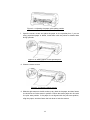
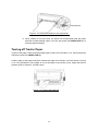
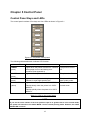
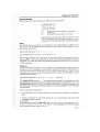
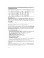
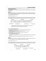
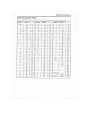
USER MANUAL
SEIKO Precision
FB – 390
Dot-Matrix Flatbed Printer
Important Safety Instructions
1.
2.
3.
Read all of these instructions carefully and thoroughly and save them for later reference.
Follow all warnings and instructions in the manual as well as marked on the product.
Unplug this product from the power outlet before cleaning. Do not use liquid or aerosol
cleaners. Use a damp cloth for cleaning.
4. Do not use this product near water.
5. Do not place this product on an unstable cart, stand or table. The product may fall, causing
serious damage to you or the product.
6. Slots and openings on the cabinet and the back or bottom are provided for air ventilation. To
ensure reliable operation of the product and to protect it from overheating, do not block or
cover these openings. The openings should never be blocked by placing the product on a
bed, sofa, rug or other similar surface. This product should never be placed near or over a
radiator or heater. This product should not be placed in a built-in installation or kiosk stand
unless proper ventilation is provided.
7. This product should be operated from the type of power source indicated on the rating label. If
you are not sure of the type of power available, consult your local dealer or an electrician.
8. Depending on the country of shipment this product may be equipped with a 3-wire
grounding-type plug, a plug having a third (grounding) pin. This plug will only fit into a
grounding-type power outlet. This is a safety feature. If you are unable to insert the plug into
the outlet, contact your local electrician to replace your obsolete outlet. Do not defeat the
safety purpose of the grounding-type plug.
9. Do not allow anything to rest on the power cord. Do not locate this product in a location so that
the power cord will be walked or driven over or on.
10. Never push objects of any kind into this product through cabinet slots as they may touch
dangerous voltage points or short out parts that could result in a risk of fire or electric shock.
Never spill liquid of any kind on the product.
11. Except as explained elsewhere in this manual, do not attempt to service this product yourself.
Opening and removing those covers that are marked “Do Not Remove” may expose you to
dangerous voltage points or other hazardous risks. Leave all servicing on those
compartments to qualified service personnel.
12. The mains plug on this equipment must be used to disconnect the mains power.
13. Unplug this product from the power outlet and leave servicing to qualified service personnel
under the following conditions:
A. When the power cord or plug is damaged or frayed.
B. If liquid has been spilled into the product.
C. If the product has been exposed to rain or water.
D. If the product does not operate normally when the operating instructions are followed.
Adjust only those controls that are covered by the operating instructions since importer
adjustment of other controls may result in damage and will often require extensive work
by a qualified technician to restore the product to normal operation.
E. If the product has been dropped or the cabinet has been damaged.
F. If the product exhibits a distinct change in performance, indicating a need for service.
Note: The contents of this manual may be changed without prior notice.
i
Table of Contents
Chapter 1 Overview.............................................................................................................. 1
Features ................................................................................................................................................ 1
Chapter 2 Preparation....................................................................................................... 3
Unpacking .......................................................................................................................................... 3
Parts Identification ...................................................................................................................... 4
Installation ......................................................................................................................................... 5
Installing the Front Table Extension Tray ................................................................... 5
Installing and Replacing the Ribbon Cassette.......................................................... 5
Connecting the Interface Cable ......................................................................................... 6
Using the Parallel Interface and the USB Interface........................................... 7
Connecting to the Power Source ...................................................................................... 7
Connecting the Power Cord ................................................................................................. 7
Turning the Power on and off .............................................................................................. 7
Chapter 3 Loading paper ............................................................................................... 8
Paper Thickness Adjustment ............................................................................................... 8
Loading Cut Sheet Paper ........................................................................................................ 9
Using Tractor Paper .................................................................................................................. 10
Loading Tractor Paper ............................................................................................................ 10
Tearing off Tractor Paper ..................................................................................................... 13
ii
Chapter 4 Printing from Your Software .................................................... 14
Setting Up Your Printer To Work With Software .............................................. 14
Chapter 5 Control Panel ............................................................................................... 15
Control Panel Keys and LEDs ......................................................................................... 15
Basic Control Panel Operations ...................................................................................... 16
Top of Form Adjustment Mode ....................................................................................... 16
Tear-off Adjustment Mode .................................................................................................. 17
Using the Setup Menu System ......................................................................................... 17
To enter the Setup Menu System and change the settings ............................... 18
To exit the Setup Menu System ......................................................................................... 18
Printing the Current Setting Report .............................................................................. 19
Options of the Setup Menu System ................................................................................. 21
Restoring Factory Printer Settings ................................................................................ 23
Using the Self Test Functions ........................................................................................... 23
Slide Pattern Printing Test .................................................................................................. 23
Maintenance Printing Test (H pattern) ....................................................................... 23
Hex Dump Mode ........................................................................................................................ 24
Appendix A .................................................................................................................................... 25
Maintenance and Fault Finding ....................................................................................... 25
Error LED on the Control Panel ..................................................................................... 27
Appendix B .................................................................................................................................... 28
iii
Specifications ................................................................................................................................ 28
General ............................................................................................................................................ 28
Print Head ..................................................................................................................................... 28
Mechanism .................................................................................................................................... 29
Paper ................................................................................................................................................. 29
Print mode specifications..................................................................................................... 30
Graphic Print Specifications ............................................................................................. 31
Parallel Interface ...................................................................................................................... 31
USB Interface .............................................................................................................................. 32
Command Code Summary .................................................................................................. 32
Epson Emulation ....................................................................................................................... 32
Select Code Pages .................................................................................................................... 35
iv
Chapter 1 Overview
Features
Thank you for purchasing this SEIKO Precision FB-390 printer.
Combing high speed, high quality output with advanced paper handing capabilities, this versatile,
24-pin, flatbed printer is ideal for a wide range of multi-part and cut-sheet printing requirements.
Reliability, flexibility and ease-of-use are key features, making the FB-390 the perfect choice for
performing demanding applications in a variety of environments.
Versatile, Reliable, Straight Paper Path
The straight paper path enables paper to feed through the printer without bending, thus reducing
the risk of paper jamming. The versatile FB-390 prints on a wide variety of paper types from 7-part
forms to labels, envelopes and reports, as well as media up to 0.45mm thick.
Easy Paper Handing
The printer has several other useful features, which help eliminate paper handing problems and
ensure quick, accurate results.
Automatic paper loading/ejection with automatic skew detection
The automatic paper load function ensures cut sheet paper fed into the printer is correctly
positioned. The FB-390 also has an automatic skew detection function, which ejects forms which
are not fed in straight.
At the touch of a button, tractor paper loaded onto the tractor is automatically set to the printing
position. When printing is completed, the paper feeds out to the front table for easy tear-off.
Zero tear-off function
This causes tractor paper to be automatically fed to the tear-off position at the edge of the window
cover, for easy tear-off at the perforations after printing. This zero tear-off capability helps
eliminate paper wastage.
Paper park function
A simple command on the control panel enables the tractor paper to be retracted (parked) outside
of the print mechanism so that after switching the paper path select lever, cut sheet paper can be
fed into the printer from the front.
After the cut sheet paper has been printed, reverse the paper path lever so that the fanfold
stationery can be advanced back into the print mechanism for the next print job.
1
Automatic Interface Switching
The FB-390 is equipped with two interface connectors and therefore accepts both parallel
(Centronics) and USB data transfer. The printer automatically detects the type of data transfer
received from the host computer and switches to the corresponding interface type.
High Resolution Graphics
A maximum resolution of 360×360 DPI enables the printer to produce fine, sharp graphics.
User- Friendly Control Panel
Current print status and access to all printer functions is available via simple commands from the
control panel. In addition, the control panel is used to access the menu system (Setup Menu
System) with complete control over the printer’s set-up functions.
Emulation
The printer supports the Epson ESC/P2 emulation as standard.
Bar Code Generator
NW-7, EAN-13, EAN-8, Code 39, Industrial 2of 5, Interleaved 2 of 5, Code 128B, and Code 128C
are built-in as standard.
2
Chapter 2 Preparation
Unpacking
Check each item against the following packing list, if any of these items are missing, please
contact your local dealer.
NOTE
Hold the bottom of printer in the box, then carefully lift it upwards. As you unpack, save
all the original packing materials if possible. They are specially designed to protect the
printer and will make repacking easy if necessary. Before you start using your new
printer, please make sure to remove all the shipping pads from the printer. Open the
window cover and remove the shipping pads made from white styrofoam.
E
C
A
B
A
D
F
Printer
D
Ribbon cassette
B Driver CD and User’s manual
E
Power cable
C Installation guidebook
F
Front table
Figure 2-1 Packing list in the printer box
3
Parts Identification
Figures 2-2 and 2-3 highlight the main components of the printer.
I
J
K
H
A
G
F
E
D
B
C
Figure 2-2 Main parts of printer (front view)
A
Paper path select lever
G
Gap adjust lever
B
Control panel
H
Carriage shaft
C
Power switch
I
Ribbon cassette cartridge
D
Cut sheet guide
J
Print head
E
Front table
K
Window cover
F
Sub friction roller
F
E
A
C
D
B
Figure 2-3 Main parts of printer (rear view)
A
Paper feed knob
D
Power supply inlet
B
USB interface connector
E
Paper guide pulley
C
Parallel interface connector
F
Tractor
4
Installation
Before placing the printer in your chosen location, consider the following guidelines:
This printer should be placed on a normal table, printer stand or desk. Be sure that the surface
is level, to avoid an uneven load on the carriage as it operates.
Do not install the printer where it may be subjected to unsuitable conditions such as:
·Where there is excessive dust.
·Where it may be splattered with oil or metallic dust.
·Where it may be exposed to direct sunlight.
·Where it may be accidentally splashed with water.
Installing the Front Table Extension Tray
Simply attach it to the front of printer by locating the support lugs in the slots at the
edge of the printer front feed.
Support lugs
Front table extension tray
Slots
Figure 2-4 Installing the front table extension tray
Installing and Replacing the Ribbon Cassette
1
2
Make sure the printer is turned OFF and disconnect the power cable.
Open the printer window cover by holding the side of the window cover as
shown in Figure 2-5.
Window cover
Sub friction roller
Figure 2-5 Opening the window cover and the Sub friction roller.
5
3
4
5
6
Pull the Sub friction roller by gripping the center area of the unit by your
forefingers. Then lift it up until it is positioned upwards towards the top of the
printer as shown in Figure 2-5.
If necessary, move and centre the print head carefully by hand.
Hold the ribbon cartridge with the knob facing upwards and turn the ribbon knob
in the direction shown by the arrow to take up any slack in the ribbon.
To install the ribbon cartridge, hold it with both hands, with the ribbon facing
down as shown if Figure 2-6.
Figure 2-6 Installing the ribbon cassette
Make sure of the following:
When you look at the print head you will find a small piece of black plastic
on the thin metal sheet of the ribbon guide. Make sure that the ribbon goes
under the piece of plastic.
Position the ribbon cartridge with the tabs on its case over the slots inside
the printer case.
With the ribbon cartridge and ribbon correctly positioned, gently push the
cartridge towards the back of printer until it clicks into place.
7
8
Move the print head from side a few times to make sure the ribbon slides into
the ribbon guides.
Having installed the ribbon, lower the sub friction roller and gently push it shut
until you hear a click. Then close the window cover.
Connecting the Interface Cable
Connect the parallel or USB interface cable as shown in figure 2-7 on the next page:
Caution
Make sure that the power switches of both printer and host computer are turned OFF before you
connect the parallel interface cable.
6
Using the Parallel Interface and the USB Interface
The parallel interface
The USB interface
Parallel interface
connector
USB interface
connector
Parallel interface
cable
USB interface
cable
Figure 2-7 Connecting the parallel interface cable and the USB interface cable
Connecting to the Power Source
Connecting the Power Cord
Plug the power cord (supplied) into the power inlet at the rear of the printer.
Check that the power switch (located on the front of the printer) is in the OFF position, and then
plug the power cord into the wall outlet.
Power switch
Power supply inlet
Power cord
Figure 2-8 Connecting the power cord to the printer
Turning the Power on and off
To turn the printer ON, press the I mark at the side of the power switch.
To turn the printer OFF, press the O mark at the side of the power switch.
7
Chapter 3 Loading paper
Paper Thickness Adjustment
Before loading cut sheet or tractor paper, you have to adjust the gap adjust lever on the front right
side of the printer.
To feed thicker papers through the printer, you need to move the gap adjust lever from its standard
position.
The lever moves the print head relative to the platen so that there is more room for the paper.
Adjusting the gap adjust lever
To obtain good quality printing and prevent problems (paper jam etc.), adjust the gap adjust lever
as shown in the Figure 3-1. The scale number # 1 shown in Figure 3-1 identifies the standard
paper thickness setting. This is the recommended setting for most papers. Use Table 3-1 to find
the recommended setting for other papers.
Gap adjust lever
Figure 3-1 Setting the gap adjust lever
Position
Copies
Thickness
5
7
0.45mm
4
6
0.36mm
3
4 or 5
0.24 to 0.30mm
2
2 or 3
0.12 to 0.18mm
1
1
0.06mm
Table 3-1 Paper thickness setting
8
Loading Cut Sheet Paper
1
2
Turn the printer on.
Set paper select lever toward the back of printer as shown in Figure 3-2.
Figure 3-2 Setting the paper select lever
3
4
Set the gap adjust lever for example to the position “1” for thin paper.
Position the left cut sheet guide by referring to the marking on the window cover.
The positions for A4 and Letter size paper are indicated on the left side of the
window cover as shown in Figure 3-3.
Figure 3-3 Adjusting the paper guide
5
Please pull out the small Front table extension tabs if the size of paper is long
and requires extra support, as shown in Figure 3-4
Front table extension tabs
Figure 3-4 Pull out the small front table extension tabs
6
Insert the paper as shown in Figure 3 - 5.
The paper is fed into the printer automatically and stops at the print start
9
position. You can set the printer to detect skew so if the paper skews during
loading, the printer detects it and automatically ejects the paper to the front
table.
Figure 3-5 Loading cut sheet
7
After the above steps, the printer is ready to print.
NOTE
The printer’s skew detection level can be set within the Setup Menu System. Be careful
with the lowest possible setting because the printer might reject the paper due to even
the smallest skew. If this happens, try a more medium setting.
Using Tractor Paper
This printer feeds tractor paper from the rear of the printer to the front.
In
Out
Figure 3-6 Feeding direction of tractor paper
Loading Tractor Paper
1
2
Turn the printer on.
Set paper select lever toward the front of printer as shown in Figure 3-7.
Figure 3-7 Setting the paper select lever
10
3
Move the left cut sheet guide to the far left as much as possible.
Figure 3-8 Moving the left cut sheet guide to the far left
4
Release the lock lever of tractor.
Figure 3-9 Releasing the lock lever of the right tractor (view from rear)
5
Move the left tractor to the left proper position (The “0”position indicates the
horizontal starting print position). When moving the left tractor to the leftmost
position, the distance between the starting print position and the centre of the
sprocket pins is 11.75cm. Lock the left tractor. Moving the right tractor to the
proper position, but do not lock it yet.
Figure 3-10 Adjusting the tractor position
6
Move the paper guide pulleys to the center between the left and right tractor.
11
Figure 3-11 Adjusting the paper guide pulley position
7
Open the tractor covers and place the paper on the sprocket pins. If you are
using preprinted paper or labels, install them with the printed or labeled side
facing upwards.
Figure 3-12 Setting paper on the sprocket pins
8 Close the tractor covers.
Figure 3-13 Close the tractor covers.
9 Slide the right tractor to the left to take up any slack in the paper, and then fasten
the lock lever to fix the tractor in position. Ensure the tractor paper is in line with
the print start position. If the paper is not aligned with the print start position,
align the paper, and then fasten the lock lever to lock the tractors.
12
The lock lever
Figure 3-14 Locking the position of the right tractor
10 When starting a new print task, the printer will automatically load the paper
before the actual printing starts. (You can also press the PARK/LOAD key to
load the paper manually.)
Tearing off Tractor Paper
To tear off the paper, make sure that printed-paper is fed to the front table. If not, switch the printer
offline then press the PARK/LOAD key.
Hold the edge of the paper and pull it towards the edge of the window cover as shown in Figure
3-15. If the perforation of the paper is not at the edge of the window cover, adjust the tear-off
position (refer to chapter 5, Control Panel)
Figure 3-15 Tractor paper tear-off
13
Chapter 4 Printing from Your Software
Setting Up Your Printer To Work With Software
The printer supports the Epson ESC/P2 emulation.
You can select the Epson LQ-570+ driver for this printer, but the best way to ensure that all the
features of your printer are supported by the software is to use the SEIKO Precision printer driver.
If the driver is not available in your software package please call your software company. You may
also check our web site for the suitable driver since we are updating the available drivers from
time to time.
Your printer is supplied with a CD-Rom including the printer drivers for Microsoft Windows 98 and
Windows 2000/XP. Please load the printer driver into your software according to the instructions
on the driver CD.
14
Chapter 5 Control Panel
Control Panel Keys and LEDs
The control panel consists of five keys and four LEDs as shown in Figure 5-1
Figure 5-1 The printer control panel
The following table details each indicator LED function:
Indicator LED
On
Off
POWER
(green)
Lights when the printer is turned on. It flashes
when paper runs out and during error
condition (See Appendix A)
The printer is turned
off.
ONLINE
(green)
Lights when the printer is online.
The printer is offline
HI-SPEED
(green)
Lights when the printer is in high speed mode.
Flashes in super high speed mode.
The printer is in the
letter quality mode.
COPY MODE
(yellow)
Lights when the printer is in COPY MODE 1.
Flashes slowly when the printer is in COPY
MODE 2.
Flashes quickly when the printer is in COPY
MODE 3.
The printer is in the
normal mode.
Table 5-1 LEDs on the control panel
NOTE
If you set the scale number of the lever position equal to or greater than 2 in the normal mode,
the printer will transfer to the COPY MODE 1 as the current printing mode. However, the COPY
MODE LED is still off.
15
Basic Control Panel Operations
You can use the five keys on the control panel to operate your printer.
ONLINE
Pressing the ONLINE button, toggles between ONLINE and OFFLINE mode.
PARK/LOAD
In the offline mode, pressing the PARK/LOAD button shortly controls feeding
tractor paper or cut sheets
LF/FF
In the offline mode, press the LF/FF key to feed the paper line by line.
Alternatively, hold the key down for 2 seconds, the printer will eject the single
sheet paper, or advance the tractor paper to the tear-off position. And if you
press LF/FF key again the tractor paper will be reversely fed to the top-of-form
position of the next page.
COPY
In the offline mode, pressing the COPY key toggles among the four modes:
NORMAL, COPY MODE 1, COPY MODE 2 and COPY MODE 3.
HI-SPEED
In the offline mode, pressing the HI-SPEED key, toggles among the HI-SPEED
mode, SUPER HIGH-SPEED mode and LETTER QUALITY mode.
NOTE
1. The printer can only print DRAFT font in the HIGH-SPEED or SUPER HIGH-SPEED
mode. If you need any other font listed in the SETUP MENU SYSTEM, please change
to the LETTER QUALITY mode.
2. SUPER HIGH-SPEED mode will be invalid when printing graphic images.
3. Push button selections may override the menu selections.
Top of Form Adjustment Mode
The top of form setting determines the margin between the top of paper and the first printed line
(the top margin).
In the ONLINE mode, press the LF/FF key for about 3 seconds to enter the top of form adjustment
mode. The ONLINE and POWER LED will blink alternating.
NOTE
Your application software usually sets your top margin. You shouldn’t need to change the
top-of-form setting very often.
Use the PARK/LOAD and LF/FF keys to alter the top of form setting:
PARK/LOAD:
Increase the top of form by 1/60 inch. You can increase the margin to a maximum
of +60 increments (+60/60 inch) from the factory setting.
16
LF/FF:
Decrease the top of form by 1/60 inch. You can decrease the margin to a
maximum of -10 (-10/60 inch) from the default setting.
Press the ONLINE key to exit and save your new setting. The POWER LED and ONLINE LED
blink simultaneously 3 times with a beep, and then the POWER LED will be on.
NOTE
To exit without saving, just turn the printer OFF.
Tear-off Adjustment Mode
There is a tear-off bar at the edge of the window cover. When you have finished printing, you
can advance the tractor paper on the tracker to the tear-off bar by the tear-off function to easily
tear off the perforated sheets. The tear-off setting determines the distance between the
perforation of tractor paper and the tear-off bar. If the default distance is not suitable for you, you
can adjust it by the printer’s tear-off adjustment feature.
With the printer online, press both the PARK/LOAD and LF/FF keys for about 3 seconds to get the
printer to enter the tear-off adjustment mode. When the printer enters this mode, the ONLINE
LED and the POWER LED blink alternately.
Use the PARK/LOAD and LF/FF keys to alter the tear-off setting:
PARK/LOAD: Press the PARK/LOAD key to adjust the distance in 1/60 inch increments. You
can maximum increase to +15/60 inch
LF/FF:
Press the LF/FF key to adjust the distance in 1/60 inch decrements. You can
maximum decrease to -15/60 inch
To exit and save your new setting, press ONLINE key. The POWER LED and the ONLINE LED
blink simultaneously for 3 times, then the POWER LED turns on. Your new tear-off setting value is
saved.
NOTE
To exit without saving, just turn off the printer.
Using the Setup Menu System
The factory settings of this printer are selected to meet the requirements of the majority of users.
However, you may want to use a different character set for a different language or you may prefer
printing in different font or style. To achieve this, you can use the Setup Menu System to create
your own printer settings by modifying or changing the factory defaults.
The Setup Menu System is divided into several groups, and each group contains a number of
17
menu lists, each list containing several settings. You can select a new setting of the menu list and
save it, or just go to the next menu list without altering the current setting.
To enter the Setup Menu System and change the settings
1. Lift the window cover of the printer.
2. Eject any paper currently in the printer (or park tractor paper) then switch the printer
ONLINE.
3. Keep pressing the PARK/LOAD key for 3 seconds.
This starts the Setup Menu System and prints the instructions for using it. The current
setting is underlined.
The print head points to the current selection in the menu.
4. Make a selection from the menu with the keys on the control panel:
Press:
To:
PARK/LOAD
Move the print head to the next menu selection. Repeat this until
you get the selection that you want.
LF/FF
Save the setting that is currently indicated by the print head
position, and go to the next menu.
ONLINE
Move to the next menu without altering the current setting.
COPY
Go to the next menu group.
5. When you have made all of your settings (remember that you don’t have to go all the way
through the menu system), switch the printer off and then turn on again.
Each time you switch the printer on it uses the new saved settings. Keep the printout of the
menu selections so that you know what the current settings are.
To exit the Setup Menu System
Turn the printer off, and then turn on again.
* New settings of the menu will be stored.
NOTE
1. You do not have to go all the way through the menu system. Once you have made all
the changes you want, you only need to exit the Setup Menu System by switching off
the printer. When you switch it on again, the printer will read and use the new settings.
2. When the compressed mode is effective, the High Speed mode and Super High Speed
mode will not be valid.
18
Printing the Current Setting Report
You can use the information in the current setting report to decide which setting you want to
change.
To print the current settings:
1.
Turn the printer off.
2.
Hold down both the PARK/LOAD and LF/FF key at the same time
3.
Turn the printer on.
The printer automatically loads paper and prints the current settings. An example
print out is shown in Figure 5-2.
19
SEIKO Precision FB-390
Current Setting Report
Current settings are FILLED .
PRINT STYLE
FONT
PITCH
PAGE LAYOUT
LINE SPACING
FORM LENGTH
PAGE SKIP
COMPRESS PRT
PRINT MODE
TEXT DIR
GRAPHIC DIR
CHARACTER
SLASH ZERO
CHARACTER SET
INTL CHAR SET
CODE PAGE
ROMAN
10 CPI
6 LPI
A4
OFF
NORMAL
BI-DIR
UNI-DIR
OFF
GRAPHICS
U.S.A.
U.S.A.
INSTALL
QUIET MODE
OFF
AUTO LF
OFF
AUTO TEAR OFF
LOADING
SKEW DETECTION OFF
SKEW LEVEL
0.5 SEC.
1.0 SEC.
003
Figure 5-2 Current Setting Report
20
Options of the Setup Menu System
The following printout in Figure 5-3 shows the selections from the Setup Menu System and is
followed by a description of how to use it in Table 5-2 (Options of the Setup Menu System).
SEIKO Precision FB-390
SETUP MENU SYSTEM
Use the PARK/LOAD key to point the print head to the desired setting.
Use the LF/FF key to store the new setting and go to the next menu.
Use the ONLINE key to go to the next menu without storing a new setting.
Use the COPY key to go to the next menu group.
Current settings are
.
New settings will be FILLED.
PRINT STYLE
FONT
PITCH
PAGE LAYOUT
LINE SPACING
FORM LENGTH
PAGE SKIP
COMPRESS PRT
PRINT MODE
TEXT DIR
GRAPHIC DIR
CHARACTER
SLASH ZERO
CHARACTER SET
INTL CHAR SET
CODE PAGE
INSTALL
QUIET MODE
AUTO LF
AUTO TEAR OFF
LOADING
SKEW DETECTION
SKEW LEVEL
To activate the newly stored settings, please turn on the power again.
Figure 5-3 Setup Menu System
21
Options
Description
FONT
Set the font for the printer to use in the absence of any font control
instructions from your software.
PITCH
Set the pitch to determine the horizontal spacing of the printed characters.
LINE SPACING
Set the vertical spacing of the printed characters. You can set it to either 6
LPI (the default setting) or 8 LPI.
FORM LENGTH
Set the length of your printer paper, for both cut sheets and continuous-feed
paper.
PAGE SKIP
Select (ON) or cancel (OFF, the default) a bottom margin of one inch.
COMPRESS PRT
Select compressed print mode or normal print mode.
TEXT DIR
Set unidirectional or bi-directional printing for text. Bi-directional (the default)
is faster because the print head prints in both directions. Unidirectional is
slower but produces better printing quality.
GRAPHIC DIR
Set unidirectional or bi-directional printing for graphics. It is set to UNI-DIR
by default for better quality.
SLASH ZERO
Select or cancel the printing of a slash (/) through zero to distinguish them
from the letter O.
CHARACTER SET
Select character set into Italic Character Table or Graphic Character Table.
INTL CHAR SET
Select among international character sets.
CODE PAGE
Select a code page
QUIET MODE
Select the printer into quiet mode. The acoustic noise is lower but the
printing speed is reduced by half.
AUTO LF
Select (ON) or cancel (OFF) the automatic advance of the paper by one line
after every carriage return command.
AUTO TEAR OFF
Enable or disable AUTO TEAR OFF function. The feed delay for the tear-off
advance can be set.
LOADING
This determines the action of the printer while the single sheet paper is front
feeding.
PUSH KEY disables automatic loading allowing loading only by pressing the
LF/FF key. The other options allow automatic feeding after the stated delay
time.
SKEW DETECTION
Enable or Disable the skew detection for front feeding.
SKEW LEVEL
Sets the Skew sensor sensitivity. 001 is the most critical while 010 is the
least. If a skew error is detected the single sheet will be automatically
ejected. Note: With setting “1” manual feed becomes highly difficult.
Table 5-2 Description of Options
22
Restoring Factory Printer Settings
You can restore to the factory printer settings without having to work through the Setup Menu
System to reset the menus.
To restore to the factory settings:
1.
Make sure that the printer is ONLINE
2.
Press and hold down the ONLINE and COPY keys on the control panel for 3
seconds.
The LED’s of the POWER and ONLINE on the control panel flash 3 times respectively at
the same time and the printer makes a beep to confirm that the printer’s factory settings
have been restored.
3.
Release the keys and switch the printer off and on again.
After these steps, the printer’s factory settings work.
Using the Self Test Functions
Slide Pattern Printing Test
One page printing of ASCII slide pattern is performed by turning power on, while pressing the
LF/FF key.
Continuous printing of ASCII slide pattern is performed by turning power on, while pressing the
ON- LINE and PARK/LOAD keys.
ASCII TEST MODE
Version: 390V X.X 20XX/XX/XX
!”#$%&’()*+,-./10123456789:;<=>?@ABCDEFGHIJKLMNOPQRSTUVWXYZ[\]^_’abcdefghijklm
!”#$%&’()*+,-./10123456789:;<=>?@ABCDEFGHIJKLMNOPQRSTUVWXYZ[\]^_’abcdefghijklmn
”#$%&’()*+,-./10123456789:;<=>?@ABCDEFGHIJKLMNOPQRSTUVWXYZ[\]^_’abcdefghijklmno
Figure 5-4 The former of English self-test
Maintenance Printing Test (H pattern)
One page printing of H pattern is performed by turning power on, while pressing the ONLINE and
LF/FF keys.
Continuous printing of H pattern is performed by turning power on, while pressing the COPY key.
23
Version:
H PRINT MODE
390V X.X 20XX/XX/XX
HHHHHHHHHHHHHHHHHHHHHHHHHHHHHHHHHHHHHHHHHHHHHHHHHHHHHHHHHHHHHHHHHHHH
HHHHHHHHHHHHHHHHHHHHHHHHHHHHHHHHHHHHHHHHHHHHHHHHHHHHHHHHHHHHHHHHHHHH
HHHHHHHHHHHHHHHHHHHHHHHHHHHHHHHHHHHHHHHHHHHHHHHHHHHHHHHHHHHHHHHHHHHH
Figure 5-5 The former of the maintenance print
Hex Dump Mode
Turning power on while pressing the PARK/LOAD key causes the printer to enter Hex Dump
mode. In this mode, if you execute the following program
10
LPRINT CHR$(27);“4”
;
20
LPRINT “ABCDEFGHIJKLMNOPQRSTUVWXYZ”
30
LPRINT CHR$(27);“5”
;
40
LPRINT “ABCDEFGHIJKLMNOPQRSTUVWXYZ”
The results of the hex dump printing will be shown as follows.
***** HEXADECIMAL DUMP *****
(0000) 1B 34 41 42 43 44 45 46 47 48 49 4A 4B 4C 4D 4E, 4ABCDEFGHIJKLMN
(0010) 4F 50 51 52 53 54 55 56 57 58 59 5A 0D 0A 1B 35 OPQRSTUVWXYZ, , , 5
(0020) 41 42 43 44 45 46 47 48 49 4A 4B 4C 4D 4E 4F 50 ABCDEFGHIJKLMNOP
(0030) 51 52 53 54 55 56 57 58 59 0D 0A
QRSTUVWXYZ,
Figure 5-6 The hexadecimal dump printing
24
Appendix A
Maintenance and Fault Finding
Introduction
Your printer requires very little routine maintenance. In fact, the best maintenance for the printer is
preventative. If you have followed the suggestions for locating it in an area free of excessive dust
and heat it will give you a long and trouble-free performance.
Periodic cleaning, replacement of the ribbon, replacement of an occasional blown fuse and, after
a very long time, replacement of the print head are about the only maintenance tasks you’ll need
to carry out. We’ll cover these items in this chapter. However, before carrying out any of these
tasks make sure that the printer has been switched off.
Cleaning dirt and dust are the biggest enemies. The print head cover will keep most dirt from the
printer mechanism, but occasional cleaning to remove paper particles is a good idea.
C
A
B
D
E
F
A
B
C
Print head
Carriage
Carriage shaft
D Sub friction roller
E Platen
F
Paper guide platform
Figure A-1
Cleaning the Cabinet
Wipe soiled parts of the printer with a clean dry cloth. Remove bits of paper, etc., using tweezers.
NOTE
When cleaning, be careful not to scratch the equipment or to bend parts, etc.
Cleaning the Carriage Shaft
The carriage shaft is coated with oil, which attracts dust, etc. wipe solid parts with a soft cloth to
clean them.
25
NOTE
Over-application of oil may cause a build up of dust and dirt with resulting printer
failure.
Cleaning the platen
Clean the platen with a soft cloth.
Intervals and Materials for Cleaning
Clean inside the printer in accordance with the following:
NOTE
Intervals cleaning:
Materials:
Every 6 months or 300 hours of operation.
(Whichever comes first)
Dry cloth (gauze or soft cloth)
Ribbon Cartridge The inked ribbon in the cartridge is a continuous loop and will print several
million characters before needing replacement. When printed characters begin to appear feint, it
is time to replace ribbon cartridge.
Replacing the ribbon is a simple matter of taking out the old cartridge and replacing it with a new
one. Before removing the old cartridge always turn off the power and allow the print head to cool,
as it can be extremely hot. Then slide the print head to the left edge to avoid damage to the print
head cable. See the ribbon installation section in Chapter 2 for details.
Problems And Solutions
The following are some of the common problems, which you may encounter when using the
printer. By implementing the solutions suggested, you should be able to resolve them.
Printer is “Dead” No Light, No Action Make sure that it is plugged in, check both ends of the
power cable. Make sure the power switch is turned on. Test the socket with another appliance to
make sure it is working, check the fuse in the plug attached to the power cable. Take your printer
to your dealer to be serviced.
Printer Won’t Work Be sure that the printer cable is plugged into both the printer and the
computer. Make sure that there is paper inserted and the ONLINE LED is on.
Printing is Feint Be sure that the ribbon cartridge is installed correctly. It must be fitted securely
into place and the ribbon must pass between the print head and the ribbon mark. Adjust the gap
adjust lever (move it upward). Replace the ribbon. Replace the print head.
26
Printing is Smudged The ribbon is in front of the ribbon mask. Remove it and then insert it
correctly. Adjust the gap adjust lever (move it downward).
Poor Dot Positioning If poor dot positioning occurs, the horizontal dot alignment has to be
performed by an authorized technician.
Characters On The Screen Don’t Match The Printed Characters Many graphics characters
and special symbols are produced by different ASCII codes on each make of computer and printer.
Compare the character set charts in your computer manual with the printer character sets.
You Selected A Printer Driver In Your Application Program But The Codes Don’t Do The
Right Thing (Or Anything) On The Printer Contact your software manufacture to check if a
driver for your printer is available.
The Paper Jams Frequently When Using Continuous Forms Make sure that the incoming and
outgoing paper is straight. Be sure that the incoming paper is not sticking.
The Paper Jams When Doing Reverse Paper Feeds Be sure that the lid is shut correctly. Don’t
tear off continuous forms while you are printing. With wider paper the right edge of the first page
may not be flat against the platen. Increase the top margin or advance to the second sheet before
you start printing.
Error LED on the Control Panel
In case of printer error, the printer enters offline state and indicates an alarm by blinking the LEDs
as shown below.
LED
The POWER LED
blinks and the ONLINE
LED is off.
Error
Paper empty or
paper jam
Cause
The printer is out of
paper or jamming
Remedy
Load paper or remove the
jammed paper
The POWER and the
ONLINE LED blink
simultaneously quickly.
Paper slant
The inserted cut
sheet paper is
slanting
Re-insert the cut sheet
paper correctly
The POWER and the
ONLINE LED blink
alternately quickly.
Home position
error
The print head carrier
mechanism is out of
position
Turn off the power and turn
it on again. If an error still
occurs, clean and lubricate
the carriage shaft
The POWER and the
ONLINE LED blink
alternately slowly.
Select lever error
The select lever is
changed after loading
paper
Return the select lever to
the correct position
The POWER LED is on
and the ONLINE LED
blinks.
Head
overheating
The print head is
overheated
Automatically cleared when
print head temperature
decreases
27
Appendix B
Specifications
General
Type
24-Pin Flatbed Dot Matrix Impact Printer
Fonts
1 DP (Draft)
7 LQ (ROMAN, SANSERIF, COURIER, PRESTIGE, SCRIPT, OCRA,
OCRB)
Emulation
Epson ESC/P2
Memory
256K bytes (*Input buffer: 132K bytes)
Interface
Parallel Interface: Centronics (IEEE 1284 NIBBLE mode Compatible)
USB Interface:USB 2.0 Full-Speed
Ribbon
Color
Black
Life
4 million characters (draft mode)
Power requirements
Environmental
conditions
Rated voltage AC 220 V
Input voltage range AC 198 to 264 V
Rated frequency range 50 to 60 Hz
Input frequency range 49.5 to 60.5 Hz
Operating temperature
5~35℃
Operating humidity
10%~80%RH(No condensation)
Storage temperature
-20~55℃
Storage humidity
5%~85%RH(No condensation)
MTBF
5,000 hours, except the print head
MTTR
Less than 20 minutes
Weight (unpacked)
Approx.7.8 Kg
Physical dimensions
(Without front table)
470×252×207mm (width/depth/height)
Print Head
Print head wire diameter
0.2mm
Wire pitch
1/180 inch
Print head life
200 million strokes/wire
28
Mechanism
MODE
10 CPI
12 CPI
15 CPI
Super
High-Speed
300CPS
340 CPS
420 CPS
80 DPI
80 DPI
80 DPI
250CPS
300 CPS
375 CPS
120 DPI
120 DPI
120 DPI
83 CPS
100 CPS
125CPS
360 DPI
360 DPI
360 DPI
Print speed
DP
LQ
Paper feed Speed
Number of columns
Paper slew speed (Continuous feed): 5.0 IPS (inches per
second)
Line spacing:
increments
1/6-inch
or
programmable
in
1/360-inch
110 columns (10 CPI)
Normal: Original + 2 copies
Copy mode 1: Original + 2~4 copies
Copy capability
Copy mode 2: Original + 6 copies-1 pass-printing
Copy mode 3: Original + 6 copies-2 pass-printing
Head gap adjustment
Manual
Resolution
360X360 DPI maximum
Paper
Cut sheet
Width: 89 to 340 mm
Length: 56 to 462 mm
Fanfold
Width: 101 to 325 mm
Paper size
Cut sheet: 0.06~0.12mm
Paper thickness
Fanfold paper:
Paper type
Cut sheet, tractor paper, label, check, post card, and envelope
Paper feed mechanism
0.06~0.12 mm – Single sheet
0.06~0.45 mm – Total
Friction: manual insertion from the front table, ejection to the
front
Tractor: insertion from the rear, ejection to the front, with the
function of tear-off and paper park.
29
Print mode specifications
Print mode
Multipart Dot Spacing
mode
(V×H inches)
Max No.
of
Columns
Character
Structure
(V×H)
Normal
10cpi
LQ
(Normal
Speed)
12cpi
15cpi
10cpi
Draft
(High
Speed)
12cpi
15cpi
10cpi
SpeedDraft
(Super-High
Speed)
12cpi
15cpi
Dark 1
Dark 2
Printing
Speed
(cps)
83
1/180×1/360
110
24×18
66
53
Dark 3
26
Normal
100
Dark 1
Dark 2
1/180×1/360
132
24×18
80
64
Dark 3
32
Normal
125
Dark 1
Dark 2
1/180×1/360
165
16×12
100
80
Dark 3
40
Normal
250
Dark 1
Dark 2
1/180×1/120
110
24×9
200
160
Dark 3
80
Normal
300
Dark 1
Dark 2
1/180×1/120
132
24×7
240
192
Dark 3
89
Normal
375
Dark 1
Dark 2
1/180×1/120
165
16×7
300
240
Dark 3
120
Normal
300
Dark 1
Dark 2
1/180×1/80
110
24×6
240
192
Dark 3
96
Normal
340
Dark 1
Dark 2
1/180×1/80
132
24×5
272
217
Dark 3
108
Normal
420
Dark 1
Dark 2
1/180×1/80
Dark 3
165
16×4
336
268
134
30
Graphic Print Specifications
Graphic type
Density
120dpi
180dpi
360dpi
Pins
24
24
24
Horizontal dot
pitch
Multipart mode
Print speed
(inch/second)
Normal、Dark 1
9.9
Dark 2
8
Dark 3
3.9
Normal、Dark 1
6.6
Dark 2
5.3
Dark 3
2.6
Normal、Dark 1
6.6
Dark 2
5.3
Dark 3
2.6
1/240 inch
1/360 inch
1/360 inch
Parallel Interface
Signal level
Input
High level: 2 to 5V, Low level: 0 to 0.8V
Output
High level: 2.4 to 5V, Low level: 0 to 0.4V
Connector Pin Assignments
Signal Pin No.
Return Line Pin No.
Signal Name
Signal Direction
1
19
/STROBE
Printer ←Host
2~9
20~27
DATA
Printer ←Host
10
28
/ACK
Printer →Host
11
29
BUSY
Printer →Host
12
30
PE
Printer →Host
13
——
SELECT
Printer →Host
14
——
/AUTO FEED
Printer ←Host
15
——
NC
NC
16
——
SIGNAL GND
Printer↔ Host
17
——
CHASSIS GND
Printer↔ Host
18
——
+5V
Printer →Host
31
——
/PRIME
Printer← Host
32
——
/ERROR
Printer →Host
33
——
SIGNAL GND
Printer ↔Host
34
——
NC
Printer →Host
35
——
PULLED UP 5V
Printer →Host
36
——
/SELECT IN
Printer← Host
31
USB Interface
USB 2.0 Full-Speed.
The following table provides the standardized contact terminating assignments by number and
electrical value for Series “A” and Series “B” connectors.
Contact Number
Signal Name
Typical Wiring Assignment
1
VBUS
Red
2
D-
White
3
D+
Green
4
GND
Black
Shell
Shield
Wire
Command Code Summary
Epson Emulation
Code
(Symbol)
Name
Code
(Hex.)
Code
(Dec.)
Print and Line Feed Execution
Carriage Return
CR
0Dh
13d
Line Feed
LF
0Ah
10d
n/180” Line Feed
ESC J
1Bh 4Ah
27d 74d
n/180” Reverse Line Feed
ESC j
1Bh 6Ah
27d 106d
Set 1/8” Line Spacing
ESC 0
1Bh 30h
27d 48d
Set 1/6” Line Spacing
ESC 2
1Bh 32h
27d 50d
Set n/180” Line Spacing
ESC 3
1Bh 32h
27d 51d
Set n/60” Line Spacing
ESC A
1Bh 41h
27d 65d
Set n/360” Line Spacing
ESC +
1Bh 2Bh
27d 43d
Form Feed
FF
0Ch
12 d
Set Form Length in Lines
ESC C
1Bh 43h
27d 67d
Set Form Length in Inches
ESC C NUL
1Bh 43h 00h
27d 67d 0d
Set Form Length in Defined Unit
ESC ( C
1Bh 28h 43h
27d 40d 67d
Select Skip-Over-Perforation
ESC N n
1Bh 4Eh
27d 78d
Cancel Skip-Over-Perforation
ESC O
1Bh 4Fh
27d 79d
Vertical Tab
VT
0Bh
11d
Set Vertical Tab Positions
ESC B
1Bh 42h
27d 66d
Select a VFU Channel
ESC /
1Bh 2Fh
27d 47d
Select VFU Positions
ESC b
1Bh 62h
27d 98d
Set right Margin
ESC Q
1Bh 51h
27d 81d
Set Left Margin
ESC l
1Bh 6Ch
27d 108d
Format Control
32
Code
(Symbol)
Name
Code
(Hex.)
Code
(Dec.)
Horizontal Tab
HT
09h
9d
Set Horizontal Tab Positions
ESC D
1Bh 44h
27d 68d
Set Character Space
ESC SP
1Bh 20h
27d 32d
Set Absolute Horizontal Tab
ESC $
1Bh 24h
27d 36d
Set Relative Dot Position
ESC \
1Bh 5Ch
27d 92d
Define Unit
ESC ( U
1Bh 28h 55h
27d 40d 85d
Set Absolute Vertical Print Position
ESC ( V
1Bh 28h 56h
27d 40d 86d
Set Relative Vertical Print Position
ESC ( v
1Bh 28h 76h
27d 40d 118d
Set Form Format
ESC ( c
1Bh 28h 63h
27d 40d 99d
Set Horizontal Motion Index (HM)
ESC c
1Bh 63h
27d 99d
Select Print Quality
ESC x
1Bh 78h
27d 120d
Select ELITE Width Mode (12CPI)
ESC M
1Bh 4Dh
27d 77d
Select PICA Width Mode (10CPI)
ESC P
1Bh 50h
27d 80d
Select 15CPI Mode
ESC g
1Bh 67h
27d 103d
Select/Cancel Proportional Mode
ESC p
1Bh 70h
27d 112d
Select Double Width Mode (one line)
SO
0Eh
14d
Cancel Double Width Mode (one line)
DC4
14h
20d
Select/Cancel Double Width Mode
ESC W
1Bh 57h
27d 87d
Select Compressed Mode
SI
0Fh
15d
Cancel Compressed Mode
DC2
12h
18d
Select Emphasized Mode
ESC E
1Bh 45h
27d 69d
Cancel Emphasized Mode
ESC F
1Bh 46h
27d 70d
Select Double Strike Mode
ESC G
1Bh 47h
27d 71d
Cancel Double Strike Mode
ESC H
1Bh 48h
27d 72d
Select Italic Mode
ESC 4
1Bh 34h
27d 52d
Cancel Italic Mode
ESC 5
1Bh 35h
27d 53d
Select/Cancel Underline Mode
ESC - n
1Bh 2Dh
27d 45d
Select Superscript/Subscript Mode
ESC S n
1Bh 53h
27d 83d
Cancel Superscript/Subscript Mode
ESC T
1Bh 54h
27d 84d
Select Print Mode
ESC ! n
1Bh 21h
27d 33d
Select/Cancel Double Height Mode
ESC w n
1Bh 77h
27d 119d
Select/Cancel Quiet Print Mode
ESC s n
1Bh 73h
27d 115d
Select Justification Mode
ESC a n
1Bh 61h
27d 97d
Select Character Style
ESC q n
1Bh 71h
27d 113d
Define and Apply a Style of Scoring
ESC ( -
1Bh 28h 2Dh
27d 40d 45d
Print Data as Characters
ESC ( ^
1Bh 28h 5Eh
27d 40d 94d
Select International Character Set
ESC R
1Bh 52h
27d 82d
Select Font Style
ESC k
1Bh 6Bh
27d 107d
Select Character Table
ESC t n
1Bh 74h
27d 116d
Print Mode
Character Set
33
Name
Code
(Symbol)
Code
(Hex.)
Code
(Dec.)
Enable Character Set 2
ESC 6
1Bh 36h
27d 54d
Cancel command ESC 6
ESC 7
1Bh 37h
27d 55d
Assign Character Table
ESC ( t
1Bh 28h 74h
27d 40d 116d
Select/Deselect User-Defined Set
ESC % n
1Bh 25h
27d 37d
Define Downloaded Characters
ESC &
1Bh 26h
27d 38d
Copy ROM Characters Set into RAM
ESC:
1Bh 3Ah
27d 58d
Select Single-Density Graphics Mode
ESC K
1Bh 4Bh
27d 75d
Select Double-Density Graphics Mode
ESC L
1Bh 4Ch
27d 76d
Select High-speed, Double-Density
ESC Y
1Bh 59h
27d 89d
Select Quadruple-Density
ESC Z
1Bh 5Ah
27d 90d
Select Graphics Mode
ESC *
1Bh 2Ah
27d 42d
Reassign Graphics Mode
ESC ?
1Bh 3Fh
27d 63d
Select Graphics Mode
ESC ( G
1Bh 28h 47h
27d 40d 71d
Print Raster Graphics
ESC .
1Bh 2Eh
27d 46d
Cancel Line
CAN
18h
24d
Delete Character
DEL
7Fh
127d
Select Printer
DC1
11h
17d
Deselect Printer
DC3
13h
19d
Cancel MSB Control Sequence
ESC #
1Bh 23h
27d 35d
Set MSB to 1
ESC >
1Bh 3Eh
27d 62d
Reset MSB to 0
ESC =
1Bh 3Dh
27d 61d
Null
NUL
00h
0d
Beeper
BEL
07h
7d
Backspace
BS
08h
8d
Initialize Printer
ESC @
1Bh 40h
27d 64d
Select Unidirectional Mode (online)
ESC <
1Bh 3Ch
27d 60d
Select Print Direction
ESC U n
1Bh 55h
27d 85d
Download Character
Bit-Image
Graphics Mode
Input Data Control
Miscellaneous
34
Select Code Pages
Format
Code No.
ESC ( t n1 n2 d1 d2 d3 (n1=3, n2=0, d1=0,1,2,3)
d2
d3 (HEX)
Name
437
1
0
U.S.A.
437GR
1
10
GRK 437
858
3
0
MULTI
851GR
4
0
GRK 851
857
5
0
TURKEY
855
6
0
CYRILLIC
860
7
0
PORTUGAL
863
8
0
CANADA
865
9
0
NORWAY
852
0A
0
EAST EUROPE
864
0D
0
ARAB NLS
866
0E
0
RUSSIAN
1253
0F
0
GRK 1253
861
18
0
ICELAND
1252
19
0
WIN LAT1
1250
1A
0
WIN LAT2
Hungarian
1B
0
HUNGARY
895
1C
0
KAMENICKY
Bulgaria
1D
0
BULGARIA
ISO-8859-15
1D
0F
ISO LTN9
Mazovia
1E
0
MAZOVIA
ISO-8859-7
1F
0
GRK 8859-7
ARAB EXT
20
0
ARAB EXT
ISO-8859-1
21
0
ISO LTN1
ISO-8850-2
22
0
ISO LTN2
KBL
23
0
KBL
ISO-8859-13
24
0
ISO LTN7
ISO-8859-9
2C
0
ISO-8859-9 TURKEY
35
This printer complies with the regulation about the maximum noise level in the work
place – 3. GPSGV, under which the highest noise level has to be 70 dB (A) or less in
accordance with ISO7779.
Maschinenlärminformations-Verordnung - 3. GPSGV, der höchste Schalldruckpegel
beträgt 70 dB(A) oder weniger gemäß ISO7779.
This unit complies with Low Voltage Directive 2006/95/EC and the EMC Directive
2004/108/EC.
Dies Gerät entspricht den Bedingungen der Niederspannungs-Vorschrift 2006/95/EC
und dem EMVG nach 2004/108/EC.
36
Company name:SEIKO PRECISION (Europe) GmbH
Address:Hermann-Buck-Weg 9, D-22309 Hamburg, Germany