1
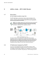
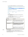
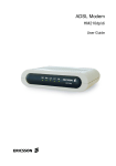
ADSL Wireless Router
HN294dp/di
User Guide
ADSL Wireless Router
HN294dp/di
User Guide
.
Copyright
Ericsson AB – 2003 All Rights Reserved
Disclaimer
The contents of this document are subject to revision without notice due to
continued progress in methodology, design, and manufacturing. Ericsson shall
have no liability for any error or damages of any kind resulting from the use of
this document.
Abstract
This User Guide provides general information about the installation of the
Ericsson ADSL Wireless Router HN294d, as well as information about
configuration possibilities.
Trademark List
Windows
Windows is a registered trademark of Microsoft
Corporation
Enclosure List
ii
EN/LZT 108 6377 R4 – September 2003
Contents
Contents
1
Introduction
1
1.1
About this User Guide
1
1.2
About the ADSL Wireless Router HN294d
1
1.2.1
Ease of Use
2
1.2.2
Wireless Features
2
1.2.3
Security
3
1.2.4
Advanced Possibilities
4
2
Hardware Description and Installation
5
2.1
Before You Start
5
2.1.1
Package Contents
5
2.1.2
Subscription for ADSL Service
6
2.2
Physical Appearance
6
2.2.1
Front Panel and LED Indicators
6
2.2.2
Back Panel and Connectors
7
2.3
Choose a Place for the Router
8
2.4
Connect the HN294d
9
2.4.1
Connect Wireless Computer(s)
9
2.4.2
Connect Computer(s) via Cables
10
2.5
Configure Client PCs
14
2.5.1
Use DHCP
14
2.5.2
Use Static IP Addresses
15
3
Initial Configuration
17
3.1
Introduction
17
3.2
Access the Configuration Wizard
18
3.3
Access the Internet
19
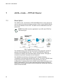
4
ADSL-mode – RFC1483 Bridge
20
4.1
Description
20
EN/LZT 108 3377 R4 – September 2003
iii
Contents
iv
4.2
IP Addresses Assigned by PPPoE
20
4.3
IP Addresses Assigned by DHCP
21
4.4
Static IP Addresses
21
5
ADSL-mode – RFC1483 Router
22
5.1
Description
22
5.2
IP Addresses Assigned by DHCP
22
5.3
Static IP Addresses
23
6
ADSL-mode – RFC1483 MER Router
24
6.1
Description
24
6.2
IP Addresses Assigned by DHCP
25
7
ADSL-mode – PPPoE Router
26
7.1
Description
26
7.2
PPPoE Termination and PPPoE Passthrough
27
7.3
IP Addresses Assigned by DHCP
27
8
ADSL-mode – PPPoA Router
28
8.1
Description
28
8.2
IP Addresses Assigned by DHCP
29
9
Advanced Configuration
30
9.1
Introduction
30
9.2
Access the Web Manager
30
9.2.1
Outline of the Web Manager
31
9.3
Overview
32
9.3.1
Connect/Disconnect to ISP
32
9.4
System
34
9.4.1
Device Information
34
9.4.2
Administration
34
9.4.3
Backup Configuration
36
9.4.4
Save Configuration
38
9.4.5
Upgrade Firmware
38
EN/LZT 108 6377 R4 - September 2003
Contents
9.4.6
Reset Router
39
9.5
Status
41
9.5.1
DSL Connection
41
9.5.2
WAN Connection
42
9.5.3
Traffic Counter
43
9.5.4
Routing Table
44
9.5.5
DHCP Table
44
9.5.6
Wireless Client
44
9.6
Configuration
46
9.6.1
DSL Configuration
46
9.6.2
LAN Configuration
46
9.6.3
WLAN Configuration
51
9.6.4
WAN Configuration
56
9.6.5
IP Route
59
9.6.6
DNS
61
9.6.7
Security
64
9.6.8
Virtual Server
70
9.6.9
IGMP Proxy
73
9.6.10
UPnP
74
10
Troubleshooting
75
10.1
Basic Functions
75
10.2
LAN Connection
75
10.2.1
How to use WINIPCFG
76
10.2.2
How to use IPCONFIG
76
10.3
WAN Connection
77
10.4
WLAN Connection
77
10.5
Reset the HN294d
78
10.6
Safety Mode
78
11
Important Information
80
11.1
Product Care and Maintenance
80
11.2
License Agreement
81
EN/LZT 108 6377 R4 - September 2003
v
Contents
11.2.1
License
81
11.2.2
Term
81
11.2.3
Limited Warranty
81
11.2.4
Intended Use
82
11.2.5
Limitation of Liability
82
11.2.6
Governing Law
82
11.3
Regulatory Information
83
11.3.1
EU Directives
83
11.3.2
Safety Approvals
83
11.3.3
EMC Approvals
84
11.3.4
Telecom Approval
85
11.3.5
Access Point Frequency Band
87
11.3.6
Caution
87
11.3.7
Power Supply
87
11.3.8
Environmental Information
87
11.3.9
Intended Use
87
Glossary 88
vi
EN/LZT 108 6377 R4 - September 2003
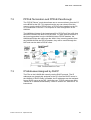
Introduction
1
Introduction
1.1
About this User Guide
This User Guide provides general information about the installation of the
Ericsson ADSL Wireless Router HN294d, as well as information about
configuration possibilities.
The following chapters are included in this guide:
Chapter 1 – “Introduction” - provides information about the ADSL
Wireless Router HN294d.
Chapter 2 – “Hardware Description and Installation” – provides a
hardware description of the product and detailed instructions about
how to install the HN294d in a PC/Windows environment
Chapter 3 – “Initial Configuration” – describes how to access the
built-in Configuration tool and run the Configuration Wizard in order
to perform the initial configuration.
Chapter 4, 5, 6, 7 and 8 – “ADSL-mode – xxx” – give a description
of each of the five pre-defined ADSL-modes included in the
Configuration Wizard.
Chapter 9 – “Advanced Configuration” - provides detailed
information about the built-in Web Manager and how to perform
advanced configuration.
Chapter 10 – “Troubleshooting” - provides tips and solution for
resolving some of the problems that might occur when installing and
using the HN294d.
Chapter 11 – “Important Information” – provides information about
License Agreement and Regulatory Information.
The Glossary includes abbreviations and explanations to technical
terms used in this guide.
1.2
About the ADSL Wireless Router HN294d
Thank you for choosing the Ericsson ADSL (Asymmetric Digital Subscriber
Line) Wireless Router HN294d. Already by the name you can see that the
EN/LZT 108 6377 R4 - September 2003
1
Introduction
HN294d is a powerful addition to your home; HN294d stands for Ericsson
quality, Wireless (WLAN) stands for freedom from cables, ADSL stands for
high-speed access to the Internet, Router stands for security/convenience
and they altogether stands for the future.
The HN294d is available in two versions: HN294dp and HN294di. Both
products offer the same features, but they rely on different types of
telephone line in order to provide the ADSL service. HN294dp offers ADSL
service over POTS (Plain Old Telephone System) lines, while HN294di
uses ISDN (Integrated Services Digital Network) lines to provide the ADSL
service.
Based on the IEEE 802.1d wireless standard the HN294d will let you
experience the freedom from cables, this means "no more annoying
cables"! With up to 11 Mbit/s in wireless speed you will have access to your
broadband network from wherever you are in your home.
With the fast and powerful HN294d you can spend less time waiting and
more time doing the things you want to do and you can do it anytime
anywhere. You can even talk on the telephone simultaneously as you surf
the Internet using your existing phone line. Using this wireless router will
give you lots of advantages over only using a simple ADSL modem (simple
ADSL modems are often referred to as "bridged" modems). With a router
you can connect multiple PCs together to use a single Internet connection
using wireless, Ethernet- or USB devices (the HN294d can handle all three
simultaneously) and you will be protected by state-of-the-art firewall
technology. But, perhaps the best thing about the HN294d is that you don’t
have to be a computer expert to use it, simple plug it in and you are done.
No complex configuration with a lot of questions you don’t know how to
answer, Ericsson has already answered them for you.
1.2.1
Ease of Use
For standard Internet access (surfing websites, playing network games,
downloading files, using peer-to-peer programs etc) all you have to do is
select an appropriate ADSL-mode in the web-based Configuration Wizard
and the technical details is set-up and managed automatically. The
HN294d comes pre-programmed with different ADSL-modes to suit
different end-users.
1.2.2
Wireless Features
It is very easy to have a wireless network up and running when using the
HN294d. As the HN294d is preconfigured, all you have to do is to install
and configure a wireless card to your computer (wireless PCMCIA-card,
wireless PCI-card or wireless USB adapter) and when your computer is
correctly setup just turn on your HN294d. Your computer will automatically
2
EN/LZT 108 6377 R4 - September 2003
Introduction
find the HN294d and assign your computer an IP address. Now, you are
ready to surf and use the Internet anywhere in your home.
Since a wireless network is more vulnerable to attacks than a traditional
wired network it is recommended to make some configuration that will
make it impossible for another user than you to access the wireless
network. The HN294d has several configuration possibilities to help you
improve the security in your wireless LAN.
In a wireless configuration the HN294d is designed to reach 50-100 meters
indoors (up to 300 meters outdoors), but when choosing a location for your
router keep in mind that this length is affected by a number of rules, such
as:
The more walls the signal has to pass, the shorter will the signal
reach.
The thicker the wall is, the shorter will the signal reach.
Keep the HN294d away from equipment that might disturb the
signal (such as Bluetooth devices, microwave ovens and 2.4 GHz
cordless phones).
1.2.3
Security
You can connect more than 250 PCs to the HN294d, all sharing the same
public IP address. This is made possible by NAT (Network Address
Translation) technology. NAT also hides your PCs from the Internet, which
serves as security protection, making it impossible to directly target your
PCs from the outside. All traffic is addressed to the HN294d, which, with its
powerful firewall, inspects all incoming and outgoing traffic and removes
malicious or dangerous packets. The firewall is a full stateful packet
inspection firewall, which means that it will not only inspect packets (like
simple firewalls) but also will remember and investigate traffic flows and
patterns to detect and prevent advanced attacks. To keep it simple, all that
you need to do is select the desired level of security.
Even though your PCs are invisible and protected from the Internet you can
still access the Internet as before, and all your Internet programs (games,
applications, peer-to-peer programs, communications applications etc) will
still work. This is handled by built-in mechanisms that recognize your
programs and allow them to access the Internet directly. Everything is
handled automatically and requires no user configuration.
The HN294 also supports pass-through of common VPN (Virtual Private
Network) implementations making it possible for the user to create secure
connections. A VPN is used to create secure connections where
confidential information needs to be sent. The VPN can be compared to a
EN/LZT 108 6377 R4 - September 2003
3
Introduction
tunnel where the information inside the tunnel is encrypted so that only the
intended target at the end of the tunnel can read the information.
1.2.4
Advanced Possibilities
The HN294d also offers sophisticated router functionality making it possible
for advanced users to create customized network scenarios as desired.
This includes the ability to set up static routes, multiple subnets, a DMZ,
etc. The Virtual server function enables you to create your own servers
behind the HN294d firewall, giving both the servers and the PCs, on which
they run, full protection. Several servers are already pre-defined, making it
easy to enable secure access to the server.
With its dual benefits of advanced functionality and ease of use, the
HN294d provides an ideal Internet access solution for a corporate
environment, a small office, and even for home users.
4
EN/LZT 108 6377 R4 - September 2003
Hardware Description and Installation
2
Hardware Description and Installation
This chapter provides a hardware description of the product and detailed
instructions about how to install the HN294d in a PC/Windows environment.
2.1
Before You Start
2.1.1
Package Contents
Check the contents of the package against the shipping contents checklist
(and figure) below. If any of the items is missing, please contact the dealer
from whom the equipment was purchased.
Figure 1 - HN294d Package Contents
Shipping contents checklist:
The ADSL Wireless Router HN294d
A Power Supply Adapter with connecting cable
Drivers & Documentation CD (including drivers for USB installation,
Acrobat Reader, and this User Guide)
EN/LZT 108 6377 R4 - September 2003
5
Hardware Description and Installation
ADSL Line Cable
Ethernet Cable
USB Cable
Quick Installation Guide
Your HN294d package may also include other materials provided by your
ADSL operator.
2.1.2
Subscription for ADSL Service
To use the ADSL Wireless Router HN294d, you will require an ADSL
service subscription from your broadband service provider.
2.2
Physical Appearance
2.2.1
Front Panel and LED Indicators
The HN294d is equipped with nine LEDs on the front panel. Although the
LED functions depend upon the operational state of the router, each LEDs
general purpose is described in the table below (from left to right):
Symbol
PWR
DIAG
LAN 1-4
USB
6
Status/Description
Unlit: Power Off.
Solid: Power On
Unlit: Power Off or initial self test of the unit is OK.
Blinking: Software is downloading or updating of
operation parameters is in progress.
Solid: Failure during initial self-test or programming
FLASH memory.
Unlit: Power Off or no Ethernet link detected to the
corresponding (1-4) Ethernet port.
Blinking: User data is going through the corresponding
(1-4) Ethernet port.
Solid: Ethernet connection is OK.
Unlit: Power Off or waiting for USB connection going up.
Blinking: User data is going through the USB port.
Solid: USB connection is OK.
EN/LZT 108 6377 R4 - September 2003
Hardware Description and Installation
Symbol
Status/Description
WLAN
Unlit: Power Off or no radio signal (WLAN card is not
present or fails to function).
Blinking: Traffic is going through the WLAN interface.
Solid: The Wireless LAN interface is ready.
DSL
Unlit: Power Off.
Blinking: ADSL line connection is handshaking or
training is in progress.
Solid: ADSL line connection is OK.
Table 1 - Description of LEDs
2.2.2
Back Panel and Connectors
The following figure illustrates the back panel of your HN294d:
Figure 2 - Back Panel of the HN294d
Description of connectors and buttons:
DSL – The DSL port is used for connecting the HN294d to the
ADSL service port (splitter/filter or phone outlet) using the supplied
ADSL line cable (RJ11 – RJ11).
LAN 1, 2, 3, 4 – The LAN ports (Ethernet 10/100 BaseT) are used
for connecting the HN294d to client PCs NIC (Network Interface
Card). One Ethernet cable (RJ45 – RJ45) is supplied.
USB – The USB port is used for connecting the HN294d to a PC
USB port using the supplied USB cable.
RESET button (tiny hole) – Used to restore your HN294d to its
original factory default settings.
(CONSOLE – The CONSOLE port should only be used by field
technicians).
EN/LZT 108 6377 R4 - September 2003
7
Hardware Description and Installation
POWER button – To power ON/OFF your HN294d.
PWR – The PWR socket is used for connecting the supplied power
supply adapter.
2.3
Choose a Place for the Router
The HN294d can be mounted on the wall or simply placed on a flat surface.
NOTE! Proper ventilation is necessary to prevent the product from
over-heating. Do not block or cover the slots and openings on the
device, which are intended for ventilation and proper operation.
In a wireless configuration the HN294d is designed to reach 50-100 meters
indoors and up to 300 meters outdoors. When choosing a location for your
router, keep in mind that the number, thickness and location of walls,
ceilings or other objects that the wireless signal must pass through may
limit the range. Also keep the HN294d away from equipment that might
disturb the signal, such as Bluetooth devices, microwave ovens and 2.4
GHz cordless phones.
If you choose to wall mount the router, use two screws and two of the
mounting slots on the bottom of the unit as shown in the illustrations below:
Figure 3 - Wall mounting of the HN294d
Note that the transparent top cover can be rotated to ensure that the logo is
correctly positioned for various mounting positions.
8
EN/LZT 108 6377 R4 - September 2003
Hardware Description and Installation
2.4
Connect the HN294d
This chapter describes how to connect the HN294d to your Wireless LAN
and/or to your LAN computer(s) using the Ethernet and/or USB interface(s).
2.4.1
Connect Wireless Computer(s)
To be able to communicate with the HN294d in a wireless LAN your
computer(s) need some kind of wireless adapter installed. This could for
example be a PCMCIA wireless card for your laptop, a wireless PCI card or
a USB wireless adapter for your desktop PCs.
NOTE! Before installing a wireless adapter find and write down the
MAC address of the product, as you might need it later when
configuring your HN294d. You will normally find the MAC address
on the product label of your WLAN adapter. MAC addresses are
given in the form 00:90:96:1A:2B:3C and only numbers (0 through
9) and letters (a through f) are allowed.
Follow the instructions below to connect the HN294d in a Wireless LAN
environment.
1. Install wireless adapter(s) according to instructions provided
together with the equipment.
2. Connect the ADSL Line
Use the provided ADSL Line cable to connect the DSL port of the
HN294d to your ADSL outlet (splitter/filter of phone outlet).
3. Connect the Power Supply
Connect the provided Power cable to the PWR socket of your
HN294d and plug the power supply adapter into a power source.
4. Power ON the HN294d
Press the Power button on the back of the HN294d to turn it on.
Check that PWR
LED turns On.
LED turns On indicating that the ADSL line
Check that the DSL
is ready. The LED is blinking when handshaking/training for the
ADSL line connection is in progress.
5. If your client PC is correctly configured it will automatically detect
and connect to the HN294d.
Check that the WLAN
LED turns On indicating that the
Wireless LAN is ready.
The HN294d comes preconfigured with a unique SSID network
name: HN294-xxxxxx, where xxxxxx is the last six digits of its
EN/LZT 108 6377 R4 - September 2003
9
Hardware Description and Installation
wireless MAC address (can be found on an information sticker on
the bottom of the router).
6. Now, the HN294d must be configured for your specific ADSL mode
and other settings. This is described in chapter 3 “Initial
Configuration”.
2.4.2
Connect Computer(s) via Cables
NOTE! If you want to use both a LAN and the USB port, connect
them to two different PCs. It is NOT recommended to connect one
PC to both a LAN and the USB ports simultaneously.
Follow the instructions below to connect the HN294d to your LAN
computer(s) using the Ethernet and/or USB interface:
1. Connect the ADSL Line
Use the provided ADSL Line cable to connect the DSL port of the
HN294d to your ADSL outlet (splitter/filter or phone outlet).
2. Connect a client PC:
- to one of the four LAN ports
Attach one end of the provided Ethernet cable to one of the four
LAN ports of your HN294d. Connect the other end to the Ethernet
adapter port on your client PC.
-- OR -- to the USB port
Insert the provided “Drivers & Documentation” CD and follow the
instructions given in the next section – “Install USB Drivers”. DO
NOT connect the USB cable until the installation program instructs
you.
3. Connect the Power Supply
Connect the provided Power cable to the PWR socket of your
HN294d and plug the power supply adapter into a power source.
4. Power ON the HN294d
Press the Power button on the back of the HN294d to turn it on.
Check the LEDs on the HN294d according to the following:
The PWR
LED turns On.
LED turns On indicating that the ADSL line is ready.
The DSL
The LED is blinking when handshaking/training for the ADSL line
connection is in progress.
10
EN/LZT 108 6377 R4 - September 2003
Hardware Description and Installation
The LAN
and/or USB
LED(s) turn On indicating a proper
connection to either a Ethernet NIC or a USB port.
5. Now, the HN294d must be configured for your specific ADSL mode
and other settings. This is described in chapter 3 – “Initial
Configuration”.
2.4.2.1
Install USB Drivers
NOTE! This should only be done if you have connected a computer
via the USB interface.
For USB connection you need to install USB drivers to your PC. Follow the
instructions below to install USB drivers and connect the HN294d to the
USB interface.
1. Close ALL Windows applications and insert the provided “Drivers &
Documentation” CD into your CD-ROM drive.
2. The CD starts automatically and the following Welcome page is
displayed:
NOTE! If Autorun does not start, select Start > Run…, type
D:\startup.exe (where D: is the letter of your CD-ROM drive) and
press Enter.
EN/LZT 108 6377 R4 - September 2003
11
Hardware Description and Installation
3. Select Install USB Driver and wait until the following window is
displayed:
4. Click Next>. Files will now be copied to your hard disk and when
completed the following window appears:
5. Connect the provided USB cable to the USB port of your HN294d.
Connect the other end to the USB port on your client PC.
6. Windows will now detect the new USB device and finalize the
installation.
12
EN/LZT 108 6377 R4 - September 2003
Hardware Description and Installation
NOTE! If the Digital Signature Not Found window (or similar)
appears, you should click Yes (or Continue Anyway) to continue
the installation. This is a warning from Microsoft that the installation
software is not a digitally signed version, but since Ericsson has
tested the software in different Windows versions this is not
necessary.
7. Click Finish to close the InstallShield wizard.
8. Click >>> Exit <<< in the Welcome page of the CD to close that
window.
EN/LZT 108 6377 R4 - September 2003
13
Hardware Description and Installation
2.5
Configure Client PCs
This chapter describes how you can check (and maybe change) the TCP/IP
settings in your computer(s) if you have problems to access the Internet.
Refer to information from your Internet Service Provider.
2.5.1
Use DHCP
If you have not been provided any IP settings from your ISP/service
provider, you should use DHCP that is the most common used method.
In Windows 98/98SE and Me:
1. From the Start menu select Settings > Control Panel and doubleclick on the Network icon.
2. Click the Configuration tab and select TCP/IP for the network
adapter (wireless, Ethernet or USB) that is connected to your
HN294d. Click the Properties button.
3. Select the IP Address tab and make sure that “Obtain an IP
address automatically” is selected. If not, select it and click OK.
4. Click OK in the “Network” dialog box and close the Control Panel.
5. Some configuration files may be copied to your hard disk and if a
“Settings Changes” message asks you to restart your PC, you
should answer Yes.
In Windows 2000:
1. From the Start menu select Settings > Control Panel and doubleclick on the Network and Dial-up Connections icon.
2. Double-click on the Local Area Connection icon for the HN294d. Be
sure to choose the correct one if you have several dial-up icons.
3. Click the Properties button.
4. Select the Internet Protocol (TCP/IP) and click the Properties
button.
5. Make sure that “Obtain an IP address automatically” is selected. If
not, select it and click OK.
6. Click OK in the “Local Area Connection Properties” dialog box and
click Close in the “Local Area Connection Status” dialog box.
14
EN/LZT 108 6377 R4 - September 2003
Hardware Description and Installation
7. Close the “Network and Internet Connections” window.
In Windows XP:
1. From the Start menu select Control Panel and
double-click on Network Connections (Classic View) or
double-click on the link Network and Internet connections
followed by Network Connections (Category View).
2. Double-click on the Local Area Connection icon for the HN294d. Be
sure to choose the correct one if you have several dial-up icons.
3. Click the Properties button.
4. Select the Internet Protocol (TCP/IP) and click the Properties
button.
5. Make sure that “Obtain an IP address automatically” is selected. If
not, select it and click OK.
6. Click Close in the “Local Area Connection Properties” and “Local
Area Connection Status” dialog boxes.
7. Close the “Network and Internet Connections” window.
2.5.2
Use Static IP Addresses
If your ISP/service provider has provided you with IP settings (for instance
IP address, subnet mask and default gateway) and/or explicitly stated that
DHCP is not used, you should do the following:
In Windows 98/98SE and Me:
1. From the Start menu select Settings > Control Panel and doubleclick on the Network icon.
2. Click the Configuration tab and select TCP/IP for the network
adapter (wireless, Ethernet or USB) that is connected to your
HN294d. Click the Properties button.
3. Select the IP Address tab.
4. Select “Specify an IP address” and enter the IP settings provided by
your ISP/service provider. Click OK.
5. Click OK in the “Network” dialog box and close the Control Panel.
EN/LZT 108 6377 R4 - September 2003
15
Hardware Description and Installation
6. Some configuration files may be copied to your hard disk and if a
“Settings Changes” message asks you to restart your PC, you
should answer Yes.
In Windows 2000:
1. From the Start menu select Settings > Control Panel and doubleclick on the Network and Dial-up Connections icon.
2. Double-click on the Local Area Connection icon for the HN294d. Be
sure to choose the correct one if you have several dial-up icons.
3. Click the Properties button.
4. Select the Internet Protocol (TCP/IP) and click the Properties
button.
5. Select “Specify an IP address” and enter the IP settings provided by
your ISP/service provider. Click OK.
6. Click OK in the “Local Area Connection Properties” dialog box and
click Close in the “Local Area Connection Status” dialog box.
7. Close the “Network and Internet Connections” window.
In Windows XP:
1. From the Start menu select Control Panel and
double-click on Network Connections (Classic View) or
double-click on the link Network and Internet connections
followed by Network Connections (Category View).
2. Double-click on the Local Area Connection icon for the HN294d. Be
sure to choose the correct one if you have several dial-up icons.
3. Click the Properties button.
4. Select the Internet Protocol (TCP/IP) and click the Properties
button.
5. Select “Use the following IP address” and enter the IP settings
provided by your ISP/service provider. Click OK.
6. Click Close in the “Local Area Connection Properties” and “Local
Area Connection Status” dialog boxes.
7. Close the “Network and Internet Connections” window.
16
EN/LZT 108 6377 R4 - September 2003
Initial Configuration
3
Initial Configuration
This chapter describes how to access the built-in Configuration tool and run
the Configuration Wizard in order to perform the initial configuration.
3.1
Introduction
The HN294d is an advanced ADSL router with several features and
supported modes that make it ideal for advanced home networking. Most
routers with similar features require complex configuration routines, but the
HN294d offers a Configuration Wizard that enables you to easily configure
the HN294d through a user friendly GUI. No special software is required on
your PC to manage and operate the HN294d. All you need is a web
browser (e.g. Internet Explorer or Netscape Communicator).
In the Configuration Wizard the user can select an ADSL-mode that fits
his/her needs. There are currently five pre-defined ADSL-modes as shown
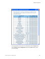
in the table below where they are briefly described. The following “ADSLmode” chapters give a deeper description of each of them.
Connection Type
Select ADSL-mode
Connect using PPPoE (sometimes
called dial-up). This type of connection
requires a Username and a Password.
RFC1483 Bridge (described in
chapter 4) or
PPPoE Router (described in
chapter 7).
Connect using PPPoA (sometimes
called dial-up). This type of connection
requires a Username and a Password.
PPPoA Router (described in
chapter 8)
Connect using DHCP or fixed IP
address (without a Username and
Password.
RFC1483 Bridge (described in
chapter 4) or
Some operators provide Username and
Password also for this type of
connection, but the login process is in
this case done from a webpage or
similar.
EN/LZT 108 6377 R4 - September 2003
RFC1483 Router (described in
chapter 5) or
RFC1483 MER Router (described in
chapter 6).
17
Initial Configuration
The HN294 still offers the possibility for advanced users to set up special
network scenarios themselves or to modify the existing ones. Refer to the
“Advanced Configuration” chapter for further information.
TIP: For advanced network scenarios, select the ADSL-mode that is closest
to your requirements and then modify it to meet your needs. This is easier
than creating a complete new profile.
3.2
Access the Configuration Wizard
Follow the steps below to access the built-in Configuration tool and start the
Configuration Wizard.
NOTE! Before performing the following steps make sure that all the
steps in chapter “Hardware Description and Installation” have been
performed.
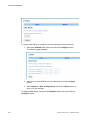
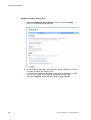
1. Start your web browser and type 192.168.0.1 (the private IP
address for the HN294d) in the URL field and press Enter.
2. To access the Configuration tool you have to login and the following
window is displayed:
3. Type admin in both the “User name” and “Password” fields that are
the default settings for the HN294d, and click OK.
18
EN/LZT 108 6377 R4 - September 2003
Initial Configuration
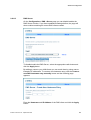
4. The welcome page of the Configuration tool is displayed:
5. Click on the Configuration Wizard button and follow the
instructions given on-screen.
6. When you have completed the wizard and reached the last page
(step 4) it is important that you click the Save Configuration button
to save all configuration settings to non-volatile memory. The
HN294d will reboot and is then ready for use.
3.3
Access the Internet
Your Internet Service Provider may have provided you additional
instructions (in the package or separately) about account setup, additional
software installation, and/or Internet usage. In that case, please follow
those instructions to complete your Internet connection setup.
If your Internet connection is not working properly your computer(s) might
need to be configured for TCP/IP. Refer to chapter 2.5 “Configure Client
PCs” to find some general descriptions.
EN/LZT 108 6377 R4 - September 2003
19
ADSL-mode – RFC1483 Bridge
4
ADSL-mode – RFC1483 Bridge
4.1
Description
RFC1483 (2684) Bridged Mode (single PVC)
In this mode the HN294d will act only as a “bridge”, meaning that the
routing functionality (firewall, NAT, UPnP, etc) will be disabled. This mode
is suitable when you only want to connect a single computer to the Internet
and want to perform all special functionality in the computer instead of the
HN294d. This mode emulates the functionality of simple ADSL modems.
Your ISP is responsible for handling all IP addresses that the PCs on your
LAN/WLAN need. The ISP can either use DHCP, PPPoE or static
assignment of IP addresses. All the three examples are transparent for the
HN294d and there is no configuration of the HN294d necessary for any of
the three scenarios. All traffic from the LAN/WLAN uses the same PVC (the
normal ISP scenario).
The following sections show three sample scenarios for which this ADSLmode is suitable. Even various combinations of these scenarios can be
implemented without any extra configuration.
4.2
IP Addresses Assigned by PPPoE
The PCs on the LAN/WLAN need to have a PPPoE client installed. The
PCs get their IP addresses from the PPPoE session assigned by the ISP.
20
EN/LZT 108 6377 R4 - September 2003
ADSL-mode – RFC1483 Bridge
4.3
IP Addresses Assigned by DHCP
The PCs on the LAN/WLAN use the DHCP protocol. The IP addresses are
dynamically assigned to the PCs from the DHCP server at the ISP. Verify
that your TCP/IP settings are set to “Obtain an IP address automatically”.
Refer to section xxx “Use DHCP” for instructions.
4.4
Static IP Addresses
The PCs on the LAN/WLAN are manually configured with static IP
addresses provided by your ISP/service provider. Refer to section xxx “Use
Static IP Addresses” for instructions.
EN/LZT 108 6377 R4 - September 2003
21
ADSL-mode – RFC1483 Router
5
ADSL-mode – RFC1483 Router
5.1
Description
RFC1483 (2684) Routed Mode (single PVC)
The RFC1483 Router mode allows a simple routed connection to the
Internet. This ADSL-mode can also be used together with NAT to let the
end-user connect an almost unlimited number of PCs on the LAN/WLAN
with only one IP address from the ISP.
NOTE! The HN294d supports RFC1483 Routed mode with static IP
addresses or with DHCP IP addresses assignment to the WAN
interface. No standard exists for DHCP over a RFC1483 Routed
connection, meaning this is a proprietary solution.
The built-in DHCP client will provide the built-in DHCP server with
information so that no configuration is needed of the built-in DHCP server
(DNS information etc is filled in automatically). PCs on the LAN/WLAN will
be assigned private IP addresses from the built-in DHCP server and the
NAT service will route the traffic to/from the WAN. All traffic from the
LAN/WLAN uses the same PVC (as in the normal ISP scenario).
5.2
IP Addresses Assigned by DHCP
The PCs on the LAN/WLAN normally use the DHCP protocol. The IP
addresses are dynamically assigned to the PCs from the DHCP server in
the HN294d. If DHCP Relay is enabled, the IP addresses can be assigned
from a DHCP server at the ISP. Verify that your TCP/IP settings are set to
22
EN/LZT 108 6377 R4 - September 2003
ADSL-mode – RFC1483 Router
“Obtain an IP address automatically”. Refer to section xxx “Use DHCP” for
instructions.
5.3
Static IP Addresses
The PCs on the LAN/WLAN are manually configured with static IP
addresses provided by your ISP/service provider. Refer to section xxx “Use
Static IP Addresses” for instructions.
EN/LZT 108 6377 R4 - September 2003
23
ADSL-mode – RFC1483 MER Router
6
ADSL-mode – RFC1483 MER Router
6.1
Description
RFC1483 (2684) Bridged Mode (single PVC) with router functionality
enabled.
A new feature of the HN294d is bridge-router mode. In this mode the user
can connect an almost unlimited number of PCs to the LAN/WLAN but still
only require one IP address from the ISP (which is the standard offering of
most ISPs today). This mode eliminates the need to place an external
router behind the bridged modem on the LAN/WLAN in order to connect
more than one computer and also takes advantage of the security aspects
of using a firewall-enabled router. Everything is handled in the HN294d
making an external router unnecessary.
NOTE! In this scenario the ISP uses a DHCP server. If the ISP
uses PPP, the “PPPoE Router” or “PPPoA Router” ADSLmode
should be used instead.
The bridge-router mode means that the device operates as a bridge to the
WAN (like in the ADSL-mode “RFC1483 Bridge”) while simultaneously
operating as a router to the LAN/WLAN.
The HN294d has a built-in DHCP client that is assigned a public IP address
from the DHCP server at the ISP at start-up. The HN294d automatically
activates the NAT (Network Address Translation) and its internal DHCP
server. The built-in DHCP client will provide the built-in DHCP server with
information so that no configuration is needed (information such as DNS,
gateway, and mask etc is filled in automatically). All traffic from the
LAN/WLAN uses the same PVC (as in the standard ISP scenario).
24
EN/LZT 108 6377 R4 - September 2003
ADSL-mode – RFC1483 MER Router
PCs on the LAN/WLAN will be assigned private IP addresses from the builtin DHCP server and the NAT will route the traffic to/from the WAN. The
HN294d offers several automatic features (such as ALG, Smart tracking,
UPnP, Firewall etc) to make Internet surfing, downloading files, and playing
network games a pleasant and trouble-free experience.
6.2
IP Addresses Assigned by DHCP
The PCs on the LAN/WLAN normally use the DHCP protocol. The IP
addresses are dynamically assigned to the PCs from the DHCP server in
the HN294d. If DHCP Relay is enabled, the IP addresses can be assigned
from a DHCP server at the ISP. Verify that your TCP/IP settings are set to
“Obtain an IP address automatically”. Refer to section xxx “Use DHCP” for
instructions.
EN/LZT 108 6377 R4 - September 2003
25
ADSL-mode – PPPoE Router
7
ADSL-mode – PPPoE Router
7.1
Description
This ADSL-mode, much like the “RFC1483 MER Router” mode, allows the
user to connect an almost unlimited number of PCs on the LAN/WLAN with
only one IP address from the ISP. All traffic from the LAN/WLAN uses the
same PVC.
NOTE! This ADSL-mode is applicable if your ISP uses PPPoE as
connection type.
The HN294d has a built-in PPPoE client that will be assigned a public IP
address from the BRAS at the ISP. The ISP uses PPPoE (or dial-up)
connection to identify users and allow them Internet access. This type of
connection requires a Username and a Password.
The HN294d automatically activates the NAT (Network Address
Translation) service and its internal DHCP server. The built-in PPPoE client
will provide the built-in DHCP server with information so that no
configuration is needed of the built-in DHCP server (DNS information etc is
filled in automatically). PCs on the LAN/WLAN will be assigned private IP
addresses from the built-in DHCP server and the NAT service will route the
traffic to/from the WAN.
26
EN/LZT 108 6377 R4 - September 2003
ADSL-mode – PPPoE Router
7.2
PPPoE Termination and PPPoE Passthrough
The “PPPoE Router” mode also allows user to connect directly from the PC
to the BRAS at the ISP. This means that the user can choose if he/she
wants to use the built-in PPPoE client, a PPPoE client installed on the PC,
or a combination of the two. This requires no extra configuration of the
HN294d.
The HN294d will detect if the incoming traffic is PPPoE or if it is traffic that
should be routed to the built-in PPPoE client, i.e. lacks PPPoE headers. If
the incoming packets from the LAN/WLAN have PPPoE headers, the
HN294d will bridge the traffic onto the WAN. If the incoming packets from
the LAN/WLAN lack the PPPoE headers, they will be routed through the
NAT and onto the built-in PPPoE client.
7.3
IP Addresses Assigned by DHCP
The PCs on the LAN/WLAN normally use the DHCP protocol. The IP
addresses are dynamically assigned to the PCs from the DHCP server in
the HN294d. If DHCP Relay is enabled, the IP addresses can be assigned
from a DHCP server at the ISP. Verify that your TCP/IP settings are set to
“Obtain an IP address automatically”. Refer to section xxx “Use DHCP” for
instructions.
EN/LZT 108 6377 R4 - September 2003
27
ADSL-mode – PPPoA Router
8
ADSL-mode – PPPoA Router
8.1
Description
This ADSL-mode, much like the “RFC1483 MER Router” mode, allows the
user to connect an almost unlimited number of PCs on the LAN/WLAN with
only one IP address from the ISP. All traffic from the LAN/WLAN uses the
same PVC.
NOTE! This ADSL-mode is applicable if your ISP uses PPPoA as
connection type.
The HN294d has a built-in PPPoA client that will be assigned a public IP
address from the BRAS at the ISP. The ISP uses PPPoA (or dial-up)
connection to identify users and allow them Internet access. This type of
connection requires a Username and a Password.
The HN294d automatically activates the NAT (Network Address
Translation) service and its internal DHCP server. The built-in PPPoA client
will provide the built-in DHCP server with information so that no
configuration is needed of the built-in DHCP server (DNS information etc is
filled in automatically). PCs on the LAN/WLAN will be assigned private IP
addresses from the built-in DHCP server and the NAT service will route the
traffic to/from the WAN.
28
EN/LZT 108 6377 R4 - September 2003
ADSL-mode – PPPoA Router
8.2
IP Addresses Assigned by DHCP
The PCs on the LAN/WLAN normally use the DHCP protocol. The IP
addresses are dynamically assigned to the PCs from the DHCP server in
the HN294d. If DHCP Relay is enabled, the IP addresses can be assigned
from a DHCP server at the ISP. Verify that your TCP/IP settings are set to
“Obtain an IP address automatically”. Refer to section xxx “Use DHCP” for
instructions.
EN/LZT 108 6377 R4 - September 2003
29
Advanced Configuration
9
Advanced Configuration
9.1
Introduction
The HN294 offers the possibility for advanced users to set up special
network scenarios themselves or to modify the existing ones.
TIP: For advanced network scenarios, use the Configuration Wizard and
select the ADSL-mode that is closest to your requirements and then modify
it to meet your needs. This is easier than creating a complete new profile.
9.2
Access the Web Manager
Follow the steps below to access the built-in Configuration tool and the
Web Manager including web pages for advanced configuration.
NOTE! By default, the built-in web pages are only accessible from
your LAN/WLAN computer(s). Refer to the “Status” chapter for
instructions on how to change settings to allow remote access.
1. Start your web browser and type 192.168.0.1 (the private IP
address for the HN294d) in the URL field and press Enter.
2. To access the Configuration tool you have to login and the following
window is displayed:
30
EN/LZT 108 6377 R4 - September 2003
Advanced Configuration
3. Type admin in both the “User name” and “Password” fields that are
the default settings for the HN294d, and click OK.
4. The welcome page of the Configuration tool is displayed:
5. Click on the Advanced Configuration button to enter the Web
Manager.
9.2.1
Outline of the Web Manager
The Web Manager is composed of three areas:
Title; Indicates the title of this management interface.
Main Menu; Includes the Overview, System, Status and
Configuration menus. By clicking of the main menus they will
expand and present the included sub-menus. Clicking on each item
will display its content in the main window accordingly.
Main Window; The main workspace containing configuration or
status information.
EN/LZT 108 6377 R4 - September 2003
31
Advanced Configuration
9.3
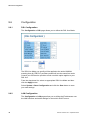
Overview
This is the start page of the Web Manager:
On this page you can see the current configuration of your HN294d.
For ADSL-modes that use PPP as connection type, you need to
Connect/Disconnect when you want to access the Internet. This is shown in
the “Action” column by either a Connect or Disconnect button.
For other type of ADASL-modes you are “Always on” which is indicated in
the “On-Line Time” column.
9.3.1
Connect/Disconnect to ISP
For ADSL-modes that use PPP as connection type you need to
Connect/Disconnect when you want to access the Internet. The default
setting in the HN294d is “Always On” meaning that when you have
performed the steps below (entered your User Name and Password) once,
the HN294d will automatically connect to your ISP whenever you use your
Internet connection.
Follow the steps below to connect to your ISP:
32
EN/LZT 108 6377 R4 - September 2003
Advanced Configuration
1. Click the Connect button in the “Action” column. The following page
appears:
2. Enter the User Name and Password provided by your ISP and
click on the Connect button.
3. Once the connection is successfully established you will return to
the Overview page where you can keep track on the “On-Line
Time”.
Disconnect:
1. Click the Disconnect button in the “Action” column. The following
page appears:
2. Click the Disconnect button.
3. Once the connection is disconnected you will return to the Overview
page where the counter for “On-Line Time” will stop and be reset.
NOTE! On the Configuration > WAN (modify) page you can select
to automatically disconnect if no traffic is detected for a specific
period (minutes). If outbound traffic is detected when the HN294d is
disconnected, it will automatically connect again.
EN/LZT 108 6377 R4 - September 2003
33
Advanced Configuration
9.4
System
9.4.1
Device Information
The System > Device Info page provides a general overview of your
HN294d including the hardware board, firmware version, and information
about the Ethernet, USB and Wireless interfaces.
9.4.2
Administration
9.4.2.1
Account
On the System > Administration > Account page you can change the
default User Name and/or Password which is recommended to avoid
unauthorized access to the configuration pages. Users with a valid User
Name and Password can only access the Web Manager. By default, both
the User Name and Password are set to admin.
34
EN/LZT 108 6377 R4 - September 2003
Advanced Configuration
To change the default User Name and/or Password, just type your new
information in the fields. If you only want to change the password, keep
admin in the “User Name” field and type your new password (in both
fields).
Confirm by clicking the Apply button. The login window then appears and
you are prompted to make a new login with your new User Name and/or
Password.
9.4.2.2
Remote Management
On the System > Administration > Remote Management page you can
manage remote client access to the HN294d from the WAN.
To enable/disable remote access proceed as follows:
1. Enter an appropriate access time in the Allow access for: field.
This is recommended if you want to temporarily enable remote
access for another user.
EN/LZT 108 6377 R4 - September 2003
35
Advanced Configuration
Select Unlimited time if you always want to have access to your
HN294 d from the Internet.
2. Click the Enable button. Information about “Seconds remaining for
remote access” is now displayed.
3. In order to disable this function, simply click the Disable button.
4. Select System > Save Configuration and click the Save button to
save your new settings.
9.4.2.3
Web Port
On the System > Administration > Web Port page you can change the
default web server port (80).
Enter a new port number in the Change the web server port to: field and
click the Apply button.
Select System > Save Configuration and click the Save button to save
your new settings.
9.4.3
Backup Configuration
On the System > Backup Configuration page you can backup the current
configuration settings to a file on your computer and also restore the
configuration from a previously saved file.
36
EN/LZT 108 6377 R4 - September 2003
Advanced Configuration
9.4.3.1
Backup
To save a backup file of your current configuration proceed as follows:
1. Click the Backup button.
2. An information window is displayed. Click OK to continue..
3. Enter a filename (or keep the default MyConfiguration) and select a
destination folder where you want to save the backup file.
NOTE! Do not modify this file, since it then will be invalid and not
accepted by the router if you want to make a restore.
9.4.3.2
Restore
To restore your configuration from a previously save file proceed as follows:
1. Click the Browse button to locate your backup file.
2. Click the Restore button.
3. An information window is displayed. Click OK to continue.
EN/LZT 108 6377 R4 - September 2003
37
Advanced Configuration
4. When the restoring is completed the following window appears:
5. Click the Save button to save the configuration (otherwise the new
settings are only valid until next reboot).
9.4.4
Save Configuration
From the System > Save Configuration page you can save all current
configuration to non-volatile memory.
All settings you apply on the pages in the Web Manager will take effect
immediately, but once you restart or turn off your HN294d the changes will
be discarded. If you want the settings to remain in effect even after the
current session, you must click the Save button on this page.
9.4.5
Upgrade Firmware
From the System > Upgrade Firmware page you can upgrade the
firmware in the HN294d.
38
EN/LZT 108 6377 R4 - September 2003
Advanced Configuration
The HN294d supports firmware upgrades via HTTP.
To transfer a new firmware file and upgrade the HN294d, follow the steps
below:
1. Download and unzip the new firmware file to your local PC.
2. In the File Name of Firmware field, click the Browse button to
locate the upgrade file.
3. Click the Upgrade button.
DO NOT turn off the HN294 during the firmware upgrade. The
upgrade process may take a while due to extensive testing of the
software. After upgrading, the original configuration settings will
remain.
4. The status of the firmware upgrade will be displayed after the
firmware upload is completed.
NOTE! In case that an upgrade fails, all LEDs will lit and the Web
Manager will not be accessible. Please refer to the
“Troubleshooting” chapter (section Safety Mode) for information
about how to access the router and make a new upgrade.
9.4.6
Reset Router
The System > Reset Router page allows you to reset your HN294.
EN/LZT 108 6377 R4 - September 2003
39
Advanced Configuration
Click the Restart button.
When restarting the system, your browser session will be disconnected.
Please wait until the device has finished restarting before attempting to
reconnect to the device.
9.4.6.1
Reset to Factory Default
If Reset to factory default settings is checked before you click the
Restart button, the settings will return to factory default settings, including
the User Name and Password.
You can also reset the HN294d to factory default settings using the Reset
button (tiny hole) on the back panel. This method is used when you cannot
access the Web Manager. A detailed description is provided in the
“Troubleshooting” chapter.
40
EN/LZT 108 6377 R4 - September 2003
Advanced Configuration
9.5
Status
9.5.1
DSL Connection
The Status > DSL Connection page shows the DSL line connection
status:
By clicking the Refresh link (above the table) all values will be updated.
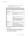
The table below describes the included parameters:
Parameter
Description
Line Mode
The HN294d supports multi-mode standard, ANSI
T1.413, G.lite and G.dmt.
Line State
Shows the status of the startup of the ADSL
connection. This could be:
Handshake mode where information is exchanged
for startup of the ADSL connection.
Training mode where the transceiver is attempting
a startup prior to entering the Show Time mode, and
Show Time mode where the transceiver has started
up, trained and is capable of passing user data.
DS / US Speed
EN/LZT 108 6377 R4 - September 2003
Shows the Downstream / Upstream speed of the
ADSL line connection.
41
Advanced Configuration
9.5.2
Parameter
Description
DS / US Latency
Displays whether a fast or interleaved latency path
is specified.
Trellis coding
Indicates if trellis coding is enabled or disabled.
Trellis coding is a method of providing better
performance in a noisy environment. It helps to
transmit at faster line rates with lower error rates,
thus providing a faster overall throughput in a
moderately noisy environment.
Line Attenuation
Indicates the signal attenuation caused by line
length. It increase with line length and frequency
and decreases as wire diameter increases.
Noise Margin
Signal to noise ratio, the ratio of good data (signal)
to bad (noise) on the line, expressed in decibels
(dB).
Loss os Signal / Frame
Indicates the loss of signals or frames detected.
CRC Error
The number of Cyclic Redundancy Checksum
generated.
Error Second
The sum of the seconds during which packet error
have occurred.
Line / System Up Time
The elapsed time from line / system startup.
WAN Connection
The Status > WAN Connection page shows the ATM PVC interface(s)
currently defined.
By clicking the Refresh link (above the table) all the values will be updated.
The table below describes the included parameters:
42
EN/LZT 108 6377 R4 - September 2003
Advanced Configuration
9.5.3
Parameter
Description
PVC Name
The name specified for the specific PVC.
VPI
Shows the VPI (Virtual Path Identifier). Valid range
is from 0 to 255.
VCI
Shows the VCI (Virtual Channel Identifier). Valid
range is from 32 to 4095 (1-31 is reserved for wellknown protocols).
Data Encap
Shows the ADSL mode connection type (RFC1483
Bridged, RFC1483 Routed, RFC1483 MER, PPPoA
or PPPoE) and the selected encapsulation type (VCMUX or LLC/SNAP).
NAT
Shows if NAT (Network Address Translation) is
enabled.
Local WAN IP
Shows the IP address your HN294d will use on the
Internet.
Traffic Counter
The Status > Traffic Counter page shows the records of data going
through the LAN, WLAN and WAN interfaces.
For each interface, cumulative totals are displayed for Transmitted (Tx) /
Received (Rx) packets and Transmitted (Tx) / Received (Rx) bytes.
By clicking the Refresh link (above the table) all the values will be updated.
EN/LZT 108 6377 R4 - September 2003
43
Advanced Configuration
9.5.4
Routing Table
The Status > Routing Table page shows the routing rules of data packets
going through the HN294d while in routing mode.
By clicking the Refresh link (above the table) all the values will be updated.
9.5.5
DHCP Table
The Status > DHCP Table page shows the DHCP client(s) who get their IP
addresses from the HN294d.
For each DHCP client, the Host Name, MAC Address, IP Address and the
Lease Time are indicated.
By clicking the Refresh link (above the table) all the values will be updated.
9.5.6
Wireless Client
The Status > Wireless Client page shows the wireless client(s) that are
associated to the HN294d.
44
EN/LZT 108 6377 R4 - September 2003
Advanced Configuration
For each wireless client, the MAC Address and the On-Line Time are
indicated.
By clicking the Refresh link (above the table) all the values will be updated.
EN/LZT 108 6377 R4 - September 2003
45
Advanced Configuration
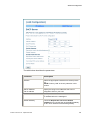
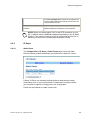
9.6
Configuration
9.6.1
DSL Configuration
The Configuration > DSL page allows you to define the DSL Line Mode.
The DSL Line Mode you specify will be applied to the entire HN294d
meaning that all ATM PVC provides created will use the same line mode.
Consult your ISP/service provider to find out which option applies to your
DSL line.
From the drop-down list, select an appropriate DSL Line Mode and then
click the Apply button.
Select System > Save Configuration and click the Save button to save
your new settings.
9.6.2
LAN Configuration
The Configuration > LAN pages allow you to define the IP addresses over
the LAN interface and make settings for the built-in DHCP server.
46
EN/LZT 108 6377 R4 - September 2003
Advanced Configuration
9.6.2.1
IP Address
On the Configuration > LAN > IP Address page you can define the IP
addresses over the LAN interface on which you can access the HN294d.
The table below describes the parameters:
Parameter
Description
Primary IP Address
The Primary IP address is used for the purpose of
system management. When it is assigned, a PC on
the LAN is able to use the specified address to
access the HN294d through Ethernet.
By default, the IP address and subnet mask are
192.168.0.1 and 255.255.255.0 respectively. This
gives that you have an available range of IP
addresses from 192.168.0.2 to 192.168.0.254 that
can be assigned to PCs on the LAN.
Secondary IP Address
If you have several IP address ranges you can apply
a secondary IP address on which LAN computers
also can access the HN294d. This is a convenient
way to access the HN294d if you have two different
subnets.
Enter your IP settings and click the Apply button.
Select System > Save Configuration and click the Save button to save
you new settings.
EN/LZT 108 6377 R4 - September 2003
47
Advanced Configuration
9.6.2.2
DHCP Server
The Configuration > LAN > DHCP Server page allows you to configure
the built-in DHCP Server.
The HN294d incorporates a DHCP (Dynamic Host Configuration Protocol)
server, which dynamically assigns IP addresses and serves as a DNS
server to the PCs on the LAN/WLAN. DHCP functionality spares you the
hassle of manually assigning a fixed IP address to each PC on the
LAN/WLAN.
NOTE! By default the DHCP Server is enabled on the private LAN
interface (192.168.0.1) but if you already have a DHCP server on
your network, you should disable this function.
Enable and configure the DHCP server:
Select the Enabled radio button and click the Configure button. The
following page appears:
48
EN/LZT 108 6377 R4 - September 2003
Advanced Configuration
The table below describes the parameters:
Parameter
Description
Interface
Select the appropriate interface from the drop-down
list.
NOTE! “Primary LAN” is the only selection in this
version.
Start IP Address
End IP Address
Specify the range of IP addresses that can be
assigned to PCs on your LAN.
DHCP lease time
Specify the time that a network device can lease an
IP address before it is reassigned.
Default Gateway
Check the Report this host as the default
gateway box to use this host as the default gateway
or fill in an IP address as the default gateway.
EN/LZT 108 6377 R4 - September 2003
49
Advanced Configuration
Parameter
Description
Domain Name Servers
You can check the Report this host as the DNS
server box to use this host as the default DNS. Or
you can uncheck the box and manually set up the
DNS IP address in the Primary/Secondary DNS IP
address fields.
The DNS server addresses will be passed to the
DHCP clients along with the IP addresses. The
DHCP clients use the DNS to map a domain name
to its corresponding IP address and vice versa.
Enter details for the DHCP Server configuration and click the Apply button.
Select System > Save Configuration and click the Save button to save
your new settings.
Enable and configure the DHCP Relay Agent:
Select the Relay Agent radio button and click the Configure button. The
following page appears:
Enter the DHCP Server IP address and click the Apply button.
Select System > Save Configuration and click the Save button to save
your new settings.
50
EN/LZT 108 6377 R4 - September 2003
Advanced Configuration
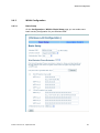
9.6.3
WLAN Configuration
9.6.3.1
Basic Setup
On the Configuration > WLAN > Basic Setup page you can make some
basic security configuration for your Wireless LAN.
EN/LZT 108 6377 R4 - September 2003
51
Advanced Configuration
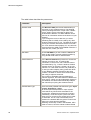
The table below describes the parameters:
52
Parameter
Description
Wireless SSID
The Wireless SSID (Service Set IDentification) is
the name of your wireless network. The HN294d
comes preconfigured with a unique name, HN294xxxxxx, where xxxxxx is the last six digits of its
wireless MAC address. This MAC address can be
found on an information sticker at the bottom of your
HN294d.
If you change the name, make sure you select
something that is unlikely to be used by any other
wireless networks close to you. The SSID is the way
to find your wireless network if there are more than
one. Your wireless clients (laptop, PC, etc) will scan
the air and find the SSID of all available networks. If
more than one, select your own.
Hide SSID
Check Hide SSID if you don’t want the HN294d to
send out the SSID to prevent network intrusion by
using WLAN sniffer tools to read the SSID.
Desired Channel
In the Desired Channel drop-down list, choose the
channel you wish to use. To optimize the
connection, be sure not to use a channel close to
one used nearby. E.g., if there is another wireless
network running on channel 1 nearby, do not use
channel 2 or 3, but rather channel 4 or preferably 5.
In case you want to deploy many (more than three
or four) different wireless networks at the same
location, it is better to use the same channel twice
than using to adjacent channels.
The number of available channels depends on
national regulation, and will therefore be different for
each country. When you have selected a channel in
the HN294d, the clients will automatically adapt to
that channel upon joining the wireless network.
Authentication Type
There are three possible Authentication types: Open
system, Shared Key or Auto.
An access point that operates in “open system”
mode will let any WLAN client associate to the
access point, whereas an access point running in
“shared key” mode will require a proof from each
client trying to connect to the access point in order
to associate. This is d one automatically and is
based on the entered WEP key (which must be the
same in the client and the HN294d).
Selecting “shared key” mode in the HN294d, will in
order to connect, force the clients to select shared
EN/LZT 108 6377 R4 - September 2003
Advanced Configuration
key mode as well.
If you select “Auto”, the HN294d will adapt to each
client’s setting, and therefore accept clients using
both “open system” and clients using “shared key”
authentication.
For maximum security, Shared key mode should be
used.
Wired Equivalent Privacy
Mechanism
The HN294d provides the security of 64- or 128-bit
encryption following the WEP (Wired Equivalent
Privacy) standard.
If your wireless clients also support “passcode” you
can use this method to automatically create the keys
to be used, instead of writing them by hand one by
one. Remember that if someone knows your
“passcode” they can also generate the same keys,
so keep the keys safe or don’t use the “passcode” at
all.
TIP! Do not use an easy “passcode” like your name.
Try to use something that cannot be related to you
as a person or can be found in a dictionary.
Make your basic security configuration for you wireless LAN as described
below:
1. Make your settings for Wireless SSID, Desired Channel and
Authentication Type.
2. In order to benefit from the increased security (optional) you can
enable WEP as the following:
Set the Wired Equivalent Privacy Mechanism to ON.
Select the Key Length (a 128-bit key provides greater security).
Enter a key. The key must consist of numbers 0 through 9 and
letters a through f only and is given in the form 1a-01-d2-8c-3b
for 64-bit WEP and 1a-01-d2-8c-3b-cc-dd-03-90-66-aa-bb-25 for
128-bit WEP.
In order to communicate with each other, all devices in the
wireless network must use the same key.
Choose which of the entered keys to use in the Default
transmission key. It is recommended to regularly change keys.
Click the Apply button.
Select System > Save Configuration and click the Save button to
save your new settings.
EN/LZT 108 6377 R4 - September 2003
53
Advanced Configuration
NOTE! If you are using a wireless client when configuring WEP,
after pressing the Apply button you will not be able to have contact
with the router until you have configured your wireless clients as
well. This is fully normal and is a proof that your network is now protected.
Remember to enter the same keys at every device on the wireless network.
Refer to your wireless client manual how to configure WEP as this will vary
depending on what operating system and wireless client you are using.
9.6.3.2
Association Control
The Configuration > WLAN > Association Control page allows you to
enable the feature “ which is an effective and easy way to secure your
wireless network from intruders. It doesn’t require any configuration of your
computer(s) but on the other hand it doesn’t encrypt the traffic like WEP.
This means that it is possible that someone could listen to your traffic, but
they cannot access your computers, router or access the Internet.
Association Control will only stop people to use or communicate over your
wireless network, i.e. they cannot access the HN294d, Internet or any or
your WLAN computers, but they can with special programs listen to your
wireless traffic. Your ordinary secure services like banking, tele-working or
accessing your e-mail is usually already encrypted but if you want to protect
people from listening to other kinds of traffic (like surfing the web to pages
that are not secured or gaming) you should enable WEP or use some kind
of VPN technology together with the Association Control.
Enable Association Control
1. Enter the MAC address of the wireless client you want to allow
access to the HN294d.
You will normally find the MAC address on the product label of your
WLAN adapter. MAC addresses are given in the form
54
EN/LZT 108 6377 R4 - September 2003
Advanced Configuration
00:90:96:1A:2B:3C and only number 0 through 9 and letters a
through f are allowed.
2. Click the Apply button and the following page appears:
3. Verify that the correct MAC address is shown in the list of
authorized clients.
4. Select System > Save Configuration and click the Save button to
save your new settings.
Add / Remove client
If Association Control is enabled and you want to add a new wireless client
(MAC address) to the list of approved clients, proceed as follows:
1. Click the Add a new client button. The following page appears:
2. Enter the MAC address of the wireless client and click the Apply
button.
EN/LZT 108 6377 R4 - September 2003
55
Advanced Configuration
3. Select System > Save Configuration and click the Save button to
save your new settings.
To remove a client, simply click Delete in the list of approved clients.
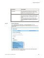
9.6.4
WAN Configuration
On the Configuration > WAN page you can create, modify and delete
ATM PVC interfaces.
The HN294d supports ATM (Asynchronous Transfer Mode) over ADSL. To
set up connections over the WAN you have to define an ATM PVC
interface for each remote connection.
You can select an existing ATM PVC interface and click the Modify link to
edit its parameters or click the Delete link to delete it.
Create a new ATM PVC Interface
If you want to add a new ATM PVC Interface, proceed as follows:
1. Click the Create a new PVC button and the following page appears:
2. Select a Data Mode and click the Next button.
3. Depending on which Data Mode were selected different pages is
now appearing. In the example below, Data Mode “PPPoE” was
56
EN/LZT 108 6377 R4 - September 2003
Advanced Configuration
selected:
4. Fill in the parameters according to information from your ISP/service
provider and click the Apply button.
5. Select System > Save Configuration and click the Save button to
save your new settings.
The parameters for creating a new ATM PVC Interface are described
below. Note that not all parameters are shown for all Data Modes.
Parameter
Description
ATM Properties
VPI
EN/LZT 108 6377 R4 - September 2003
Identifies the VPI (Virtual Path Identifier). The valid
range is from 0 to 255.
57
Advanced Configuration
Parameter
Description
VCI
Identifies the VCI (Virtual Channel Identifier). The
valid range is from 32 to 4095 (1 to 31 are reserved
for well-known protocols).
ATM Service Type
Supported ATM Service Types are UBR, CBR,
VBR-nrt and VBR-rt.
PCR (Peak Cell Rate)
Identifies the PCR cells per second. Valid values are
min. 10 and max 2500.
Encapsulation Type
Supported Encapsulation Types are VC-MUX or
LLC/SNAP.
IP Configuration
Local WAN IP Address
In Router mode, selecting None means that you
have a public LAN IP address.
If you select Specify an IP Address, you can
specify a WAN IP address provided by your
ISP/service provider for your HN294d.
If Server assigned IP Address is selected, the
HN294d will get a dynamic WAN IP address when
connecting to the remote server or ISP.
NOTE! If a fixed WAN IP is entered, this IP address
and the subnet mask MUST NOT be the same as
the public LAN interface.
PPP Configuration:
User Name/Password
The User Name and Password used to access the
remote server or ISP.
Service Name
The name of your PPP service.
Service Server
Session established by
Check Dial on Demand if you want the HN294d to
automatically dial the ISP when any client PC sends
out a request for connection. In this case, you can
disconnect the PPP session by clicking the
Disconnect button on the “Overview” page.
Enter a value for idle time out (when the PPP
session will be automatically terminated if no activity
is detected.
58
EN/LZT 108 6377 R4 - September 2003
Advanced Configuration
By enabling Always On a periodic echo request will
be sent to the ISP that prevents the connection from
being closed by the ISP.
Enable NAT on this
interface
Select this option if you want to enable NAT
(Network Address Translation) on the interface.
NOTE! When you initially add a PVC for the PPP connection to your
ISP, a default routing of 0.0.0.0 is added automatically to the IP Static
Routing. If you set up more than one PVC profile and the first PVC is
deleted, you will have to manually add the default routing.
9.6.5
IP Route
9.6.5.1
Static Route
The Configuration > IP Route > Static Route page shows the Static
Routes currently created and allows you to add new or delete IP routes.
A Static IP Route is a manually defined path that determines the datatransmitting route. If your local network is composed of multiple subnets,
you may want to specify a routing path to the routing table.
Follow the steps below to create a new route:
EN/LZT 108 6377 R4 - September 2003
59
Advanced Configuration
1. Click the Create a new route button. The following page appears:
2. Enter parameters according to information in the table below and
click the Apply button.
3. Select System > Save Configuration and click the Save button to
save your new settings.
Description of parameters when creating a new Static Route:
Parameter
Description
Destination Address and
Netmask
Identifies the destination IP address and netmask of
the network where data packets are to be sent.
For default route enter 0.0.0.0 or leave the fields
blank.
Forward packets to
Select Gateway Address and enter the IP address
of the gateway on the LAN where data packets are
to be sent. This is to be configured only when the
LAN interface is configured as a route.
or
Select Interface and from the drop-down list select
the ATM PVC interface where data packets are to
be sent.
9.6.5.2
Dynamic Routing
On the Configuration > IP Route > Dynamic Routing page you can
enable/disable the Routing Information Protocol (RIP) that will help routers
to determine optimal routes.
60
EN/LZT 108 6377 R4 - September 2003
Advanced Configuration
By default RIP is disabled and you can enable RIP on both the WAN and
Primary LAN interfaces. The RIP values can be customized for both
Receive and Transmit mode. Receive Mode incorporates the RIP
information when receiving RIP packets and Transmit Mode broadcasts the
routing table.
To enable/disable RIP follow the steps below:
1. Select an Interface Name from the drop-down list.
2. To enable RIP, select the appropriate RIP version in the drop-down
lists for both Receive and Transmit mode.
To disable RIP, select RIP disabled from the drop-down lists.
3. Click the Apply button.
4. Select System > Save Configuration and click the Save button to
save your new settings.
9.6.6
DNS
9.6.6.1
DNS Relay
On the Configuration > DNS > Relay page you can disable/enable the
DNS Relay function. If you have established settings before, the page will
show the current DNS Relay status.
EN/LZT 108 6377 R4 - September 2003
61
Advanced Configuration
To enable DNS Relay or modify the current settings proceed as follows:
1. Select the Enabled radio button and click the Configure button.
The following page appears:
2. Specify up to three DNS Server IP addresses and click the Apply
button.
3. Select System > Save Configuration and click the Save button to
save your new settings.
To disable DNS Relay, just select the Disabled radio button and click the
Configure button.
62
EN/LZT 108 6377 R4 - September 2003
Advanced Configuration
9.6.6.2
DNS Server
On the Configuration > DNS > Server page you can disable/enable the
DNS Server function. If you have established settings before, the page will
show a table containing all current DNS clients created.
To disable/enable the DNS Server, select the appropriate radio button and
click the Apply button.
By adding a name to your LAN clients you can reach them by using names
instead of IP addresses. To create a new hostname entry click the Create a
new DNS hostname entry manually button and the following page
appears:
Enter the Hostname and IP Address of the DNS client and click the Apply
button.
EN/LZT 108 6377 R4 - September 2003
63
Advanced Configuration
Select System > Save Configuration and click the Save button to save
your new settings.
9.6.7
Security
9.6.7.1
Firewall
On the Configuration > Security > Firewall page you can select the
desired security level for the built-in firewall.
To simplify the configuration you can select a general security level (Low,
Medium or High) for the firewall.
Low does not imply a low level of security, but differs from High in that High
implement more restrictive rules, allowing fewer programs to be able to
pass through the firewall. Even the Low setting offers a high level of
security since the firewall inspects all traffic and blocks attacks before they
can reach your PCs.
If you select Off, the firewall will be disabled and if you select Block, all
traffic to/from the Internet will be blocked.
You can click the link The table of default policies for various security
levels at he bottom of the page to see which applications are allowed for
the different security levels:
64
EN/LZT 108 6377 R4 - September 2003
Advanced Configuration
Set an appropriate security level for the firewall and click the Apply button.
Select System > Save Configuration and click the Save button to save
your new settings.
EN/LZT 108 6377 R4 - September 2003
65
Advanced Configuration
Modify or delete existing rules
1. Select the Advanced (User Define) option and click the Apply
button. The following page appears:
2. At the bottom of the page, select between which interfaces you want
to modify or delete the existing rules.
If you have not created a secondary LAN (see Configuration > LAN)
you can only create rules “between WAN and Primary LAN”.
Click the Configure button and the following page appears:
66
EN/LZT 108 6377 R4 - September 2003
Advanced Configuration
3. Click the Modify link next to the rule you want to modify.
4. To delete an existing rule, click the Delete link.
NOTE! If you delete any of the predefined entries, the service type
of the deleted entry will be blocked. This means that the LAN PCs
will not be able to access its corresponding service. If you want to
filter a specific computer from accessing certain Internet services or
locations, you should create additional filter rules.
5. To create a new rule, click the Create a new filtering rule button.
The following page appears:
EN/LZT 108 6377 R4 - September 2003
67
Advanced Configuration
6. Enter parameters according to the descriptions below and click the
Apply button.
7. Select System > Save Configuration and click the Save button to
save your new settings.
Description of parameters when creating a new filtering rule:
68
Parameter
Description
Protocol Type
It governs the information flow within a
communications infrastructure. You may select the
protocol from the drop-down list and then enter the
port number that identifies the service, e.g. web
service is on port 80 and FTP on port 21.
Local Side
IP Address and Netmask
If you wish to filter packets originating from a certain
node, enter the IP address and subnet mask that
identifies this node on the network.
Remote Side
IP Address and Netmask
If you wish to filter packets addressed to a certain
node, enter the IP address and subnet mask that
identifies that destination node on the Internet. The
Netmask field is disregarded if you leave it as
0.0.0.0.
EN/LZT 108 6377 R4 - September 2003
Advanced Configuration
9.6.7.2
Parameter
Description
Port Range
Enter the starting and ending port numbers that
identify the service that you want to filter, e.g. web
service is on port 80 and FTP on port 21.
Direction
Choose whether to filter the packets that are
incoming (In Bound) or outgoing (Out Bound) with
respect to the interface. The action can be Allow or
Block.
Each data packet that enters will undergo data
filtering. Data packets are either blocked or allowed
to pass, depending on whether or not a match is
found.
Intrusion Detection
On the Configuration > Security > Intrusion Detection you can
enable/disable the intrusion detection function and also see and modify the
existing rules.
To enable/disable the intrusion detection function select the appropriate
radio button and click the Apply button.
EN/LZT 108 6377 R4 - September 2003
69
Advanced Configuration
To modify the existing rules, click the Modify Rules button and the
following page appears:
Make your changes and click the Apply button.
Select System > Save Configuration and click the Save button to save
your new settings.
9.6.8
Virtual Server
The Configuration > Virtual Server page shows the Virtual Server(s)
currently created and allows you to create new server(s) and to setup a
DMZ zone for one of your LAN computers.
The HN294d implements NAT (Network Address Translation) to allow your
entire local network to appear as a single machine to the Internet. The
typical situation is that you have local servers for various services and you
70
EN/LZT 108 6377 R4 - September 2003
Advanced Configuration
want to make them publicly accessible. With NAT applied, the internal IP
addresses of these servers will be translated to a single IP address that is
unique on the Internet. The NAT function not only eliminates the need for
multiple public IP addresses, but also provides a measure of security for
your LAN/WLAN.
When the HN294d receives an incoming IP packet requesting access to
your local server, the router will recognize the service type according to the
port number in this packet (e.g. port 80 indicates HTTP service and port 21
indicates FTP service). By specifying the port number, you tell the router
which services should be forwarded to which local IP addresses you
specify.
NOTE! After you have set up a virtual server you should modify the
filter rules for those ports and services you set up on the virtual
server. This is because the firewall uses these filter rules to protect
the route.
In the virtual server list table, you may modify or delete an entry by simply
clicking the Modify or Delete link for that entry.
Create a new virtual server
To add a new virtual server service entry proceed as follows:
1. Click the Create a new server button and the following page
appears:
2. Enter parameters according to the description in the table below
and click the Apply button.
EN/LZT 108 6377 R4 - September 2003
71
Advanced Configuration
3. Select System > Save Configuration and click the Save button to
save your new settings.
Description of parameters when creating a new virtual server:
Parameter
Description
ATM PVC Name
Select the ATM PVC interface from the drop-down
list.
External Packet
Protocol
Select the protocol type to be used by the service
that will be forwarded.
TCP/IP Port
Select User Define as and enter a port number
or
Select one of the Pre-defined ports from the dropdown list.
The HN294d supports a port mapping function that
translates a standard port number to a non-standard
port number. Incoming data packets, sent to a
specific IP port, could be mapped to the port you
specify. The most often used port numbers are: 21
(FTP), 80 (HTTP), 23 (Telnet) and 25 (SMTP).
Internal Host
IP Address
Enter the IP address of the internal server to which
the packets are forwarded.
TCP/IP Port
Enter the port number you wish to use for your
internal server. If “Pre-defined” was selected above,
the port number will be filled in automatically.
Create a DMZ zone
With the help of the Virtual Server you can also create a DMZ zone for one
of your LAN computers. When a DMZ zone is created, all ports will be
redirected to this IP address. This may be useful if playing Internet games
and having problems with NAT and Firewall
To create a DMZ zone follow the steps below:
72
EN/LZT 108 6377 R4 - September 2003
Advanced Configuration
1. Click the Setup DMZ host button and the following page appears:
2. Enter parameters according to the description in the table below
and click the Apply button.
3. Select System > Save Configuration and click the Save button to
save your new settings.
Description of parameters when setting up a DMZ Host:
9.6.9
Parameter
Description
ATM PVC Name
Select the ATM PVC interface from the drop-down
list.
IP Address
Enter the IP address of the LAN computer you want
to have in the DMZ zone.
IGMP Proxy
On the Configuration > IGMP Proxy page you can select to enable IGMP
proxy. When enabled it will listen to IGMP subscriptions from your LAN
computers.
Select Enabled on PVC and from the drop-down list select the appropriate
ATM PVC interface. Click the Apply button.
EN/LZT 108 6377 R4 - September 2003
73
Advanced Configuration
Select System > Save Configuration and click the Save button to save
your new settings.
9.6.10
UPnP
On the Configuration > UPnP page you can enable the UPnP function.
Universal plug and play (UPnP) is a networking architecture that provides
compatibility among networking equipment, software and peripherals of the
400+ vendors that are part of the Universal Plug and Play Forum. UPnP
works with wired or wireless networks and can be supported on any
operating system.
When UPnP is enabled it will help your programs to pass the NAT and it
will also appear as a UPnP device on your network. Future programs will
use this device for different purposes. UPnP can be considered as a
security hole, but there are great advantages too to use it. Programs like
MSN Messenger uses UPnP.
To enable the UPnP function just check the Enable UPnP IGD Function
box and click the Apply button.
Select System > Save Configuration and click the Save button to save
your new settings.
74
EN/LZT 108 6377 R4 - September 2003
Troubleshooting
10
Troubleshooting
This chapter provides tips and solutions for resolving some of the problems
you might encounter when using your HN294d. If the suggested solutions
do not resolve your issue, contact your system administrator or Internet
Service Provider.
10.1
Basic Functions
Indication/Symptom
What to do
No LEDs light up on my
HN294d and it will not turn
on.
Check that the power adapter is connected to your
HN294d and into a power outlet.
Make sure that the power switch on the back of the
HN294d is set to On.
NOTE! Only use the power adapter provided with
the HN294d. Using any other adapter may damage
your router and violate your warranty.
10.2
LAN Connection
Indication/Symptom
What to do
The PCs on the LAN
cannot access the HN294d
Check that the power adapter is connected to your
HN294d and into a power outlet.
Make sure that your HN294d is turned On.
Check the network cable and make sure that there
is a physical connection between your computer and
the HN294d and that the LAN and/or USB LED lit
(depending on which interface you used for
connection).
Use the WINIPCFG (Windows 95/98/Me) or
IPCONFIG (Windows NT/2000/XP) utility described
below to make sure that your computer has a
compatible IP address. This utility is used mainly to
view, release and renew your IP address
configuration.
EN/LZT 108 6377 R4 - September 2003
75
Troubleshooting
10.2.1
How to use WINIPCFG
Use WINIPCFG if your PC is running Windows 95, 98 or Me:
1. From the Start menu select Run… .
2. Type winipcfg and click OK. The “IP Configuration” dialog box
appears.
3. From the scroll down menu at the top, select the network card that
you are using. This is important if you have more than one network
card.
4. Make sure that the Default gateway is the IP address of your
HN294d. If it is not, you will not be able to connect to the Internet.
If you are using DHCP, click the Release and then the Renew
buttons to receive the correct IP settings.
If you manually set your network settings, make sure that the IP
address of your HN294d is set in the Gateway portion of the TCP/IP
settings in your network settings.
5. Click OK to close the “IP Configuration” dialog box.
10.2.2
How to use IPCONFIG
Use UPCONFIG if your PC is running Windows NT, 2000 or XP:
1. From the Start menu select Programs > Accessories >
Command Prompt. The “Command Prompt” window appears.
2. Type ipconfig to display your IP configuration.
3. Make sure that the Default gateway is the IP address of your
HN294d. If it is not, you will not be able to connect to the Internet.
If you are using DHCP, type ipconfig /release and when the C:\>
prompt appears again type ipconfig /renew to receive the correct
IP settings.
4. Close the “Command Prompt” window.
76
EN/LZT 108 6377 R4 - September 2003
Troubleshooting
10.3
WAN Connection
Indication/Symptom
What to do
I can access the HN294d
but cannot connect to my
ISP.
Make sure that the HN294d is connected properly
according to the installation instructions. If the DSL
LED on the front panel is Off or keeps flashing, there
may be a problem with the cable connection to the
HN294d.
Make sure that the right connection type (ADSL
mode) is used in the Configuration Wizard
(according to instructions from your ISP/service
provider).
If you connect using a User Name and Password,
make sure you type it exactly as provided, i.e.
distinguish between uppercase and lowercase
letters.
Verify that you are in accordance with your ISP
service agreement before sharing Internet access.
Some ISP’s do not care if you share your broadband
connection while others will explicitly restrict this
type of activity.
10.4
WLAN Connection
Indication/Symptom
What to do
I cannot find the MAC
address of my WLAN
adapter.
You will normally find the MAC address on the
product label of your WLAN adapter. If not, click
Start > Run… type command and click OK. In the
command window that appears, type ipconfig /all
and hit Enter. You will then find the MAC address
listed as physical address under your wireless
adapters.
I have problems getting a
wireless connection
If you have enabled WEP, try disabling that. When
the wireless network runs smoothly, you may then
enable WEP. Remember to enter the same keys at
every device on the wireless network.
Try setting up the connection with the client in the
same room. Remember that walls and ceilings will
reduce the operating range. Also, other devices
emitting radiation at the same frequency, such as
EN/LZT 108 6377 R4 - September 2003
77
Troubleshooting
Bluetooth devices, microwave ovens and 2.4 GHz
cordless phones might interfere with your wireless
LAN.
Furthermore, you may want to consider
repositioning the HN294d (e.g. wall mount it).
10.5
Reset the HN294d
Failure to access your HN294d may occur if the router is configured
incorrectly or if you simply forget your login Username and Password. You
may end up in a situation where restoring the original default settings is the
only option.
The following procedure will reset ALL configurable values back to their
original default, including the login Username and Password.
1. Make sure your HN294d is turned On.
2. By using the tip of a pen, press the Reset button (tiny hole) to the
left of the power switch at the back of the HN294d.
3. Keep the button pressed for at least 10 seconds before releasing it.
4. The HN294d will reboot and comes then online with factory default
settings.
10.6
Safety Mode
The HN294d is equipped with a special Safety Mode that is used only if a
software upgrade fails. In case that an upgrade fails, all LEDs will lit and the
Web Manager is not accessible.
Follow the steps below to access the router again and to make a new
upgrade:
1. Your computer must be set to static IP address (within the range
192.168.0.2 to 192.168.0.253) and subnet mask 255.255.255.0.
2. Start your web browser and type 192.168.0.1 (the private IP
address for the HN294d) in the URL field. The following page
appears:
78
EN/LZT 108 6377 R4 - September 2003
Troubleshooting
3. In the File Name of Firmware field, click the Browse button to
locate the upgrade file.
4. Click the Upgrade button.
DO NOT turn off your HN294d during the firmware upgrade. The
process may take a while due to extensive testing of the software.
After upgrading, the original configuration settings will remain.
5. The status of the firmware upgrade will be displayed after the
firmware upload completed
6. After a successful upgrade the static IP address on your computer
should be changed to the previous settings (normally “Obtain an IP
address automatically”).
EN/LZT 108 6377 R4 - September 2003
79
Important Information
11
Important Information
11.1
Product Care and Maintenance
NOTE! These are important guidelines for safe and efficient use of
your device. Read this information before using your Ericsson ADSL
Wireless Router HN294d.
Your ADSL Wireless Router HN294d is a highly sophisticated electronic
device. To get the most out of your product, be sure to read the following
text about product care, safety and efficient use.
Do not expose the product to liquid or moisture.
Do not expose the product to extreme temperatures, neither hot nor cold.
Do not expose the product to lit candles, cigarettes, cigars, open flames,
etc.
Do not drop, throw or try to bend the product. Rough treatment may
damage the product.
Do not attempt to disassemble your product. The warranty is no longer
valid if the warranty seal has been broken. The product does not contain
consumer serviceable components. Service should only be performed by
Certified Service Centers.
Do not allow children to play with the product as it contains small parts that
could be detached and create a choking hazard.
Avoid using this telephone equipment during an electrical storm. There
may be a remote risk of electric shock from lightning.
Use only original Ericsson components and replacement parts. Failure to
do so may result in performance loss, damage to the product, fire, electric
shock or injury; and will invalidate the warranty.
Use only the power supply adapter that comes with the unit. Replacement
power supply adapters can be obtained from Ericsson upon request.
Treat the product with care, keep it in a clean and dust free place. Use only
a soft, damp cloth to clean the product.
80
EN/LZT 108 6377 R4 - September 2003
Important Information
11.2
License Agreement
This is a legal agreement, Agreement, between you, Licensee, the recipient
of the enclosed Software on compact disc, diskette or any other media and
any upgrades thereof, and Ericsson AB, the Vendor. By opening the sealed
software package and/or using the software you are agreeing to be bound
by the terms of this Agreement.
11.2.1
License
The Licensee is hereby granted a non-transferable, non-exclusive;
restricted right and license to use the software included herein, software.
However, the Software licensed hereunder may be delivered in an
inseparable package also containing other software programs than the
Software.
You may: (a) use the enclosed Software on a single Ericsson product; (b)
make copies of the Software solely for purposes of backup. The copyright
notice must be reproduced and included on a label on any backup copy.
You may not: subject to when applicable, the EC Council Directive of May
14, 1991 on the legal protection of computer programs (91/250/EEG)
("Software Directive" Article 6) distribute copies of this Software or its
documentation to others; modify, rent, lease or grant your rights to this
Software to third parties (except in the event the Ericsson product
containing an item of Software is transferred to a third party and provided
the transferee agrees in writing to be bound by the terms of this License
Agreement; translate, reverse engineer, decompile, disassemble or
otherwise alter the Software or its documentation or disclose any
information designated as confidential or proprietary at the time of
disclosure or, by nature, is confidential or proprietary.
11.2.2
Term
Your license remains effective from the date of receipt until terminated. You
can terminate it at any other time by destroying the Software together with
all copies of the Software in any form. Your license will also automatically
terminate without notice if you fail to comply with any term or condition of
this Agreement. Upon any termination you must destroy all copies of the
Software in any form.
11.2.3
Limited Warranty
Vendor warrants the media, on which the Software is provided, to be free of
defects in materials and workmanship under normal use for ninety (90)
days after the date of receipt. The Vendor's and its suppliers' entire liability
EN/LZT 108 6377 R4 - September 2003
81
Important Information
and your exclusive remedy under this warranty (which is subject to you
returning the Software to an certified reseller with a copy of your receipt)
will be, at Vendor's option, to replace the disc(s)/ diskette(s) or refund the
purchase price for the Software and terminate this Agreement.
Except for the above express limited warranties, Vendor and its suppliers
make and you receive no warranties or conditions either express, implied,
statutory or otherwise and Vendor and its suppliers specifically disclaim any
implied warranties of merchantability and fitness for a particular purpose.
Vendor does not warrant that the Software will be uninterrupted or error
free. You assume the responsibility for the selection of the program and
hardware to achieve your intended results; and for the installation, use and
results obtained from the Software.
Some jurisdictions do now allow limitations on duration of an implied
warranty, so the above limitation may not apply to you.
11.2.4
Intended Use
The Software shall be used in accordance with the instructions and for its
intended use and purpose only. The software or part of it is not permitted to
be used in form example life support systems, nuclear facility applications,
missile technology, chemical or biologized industry or of flight navigation or
communication of air, ground support equipment or other similar business,
if failure to perform on behalf of the software in any way, could result in
personal injury, death, damage or tangibles or environmental damage.
11.2.5
Limitation of Liability
If no event shall Vendor or its suppliers be liable for any indirect or
consequential losses or damages whatsoever including loss of data, loss of
business, loss of profits, business interruption or personal injury arising out
of the use of or inability to use this Software. Vendor and its supplier’s
entire liability under this Agreement shall be limited to the amount actually
paid by Licensee for the Software.
11.2.6
Governing Law
The validity, construction and performance of this Agreement shall be
governed by the laws of Sweden.
82
EN/LZT 108 6377 R4 - September 2003
Important Information
11.3
Regulatory Information
11.3.1
EU Directives
The HN294d meet the following EU directives for the CE-mark:
73/23/EEC, Low Voltage Directive (LVD)
89/336/EEC, Electromagnetic Compatibility Directive (EMC)
1999/5/EC, Radio Equipment and Telecommunication Terminal
Directive (R&TTE).
11.3.1.1
Declaration of Conformity
11.3.2
Safety Approvals
The HN294d is approved according to the following safety standards:
UL 1950, 3rd Ed.
EN/LZT 108 6377 R4 - September 2003
83
Important Information
CAN/CSA C22.2 No. 950-95
IEC 60950 2nd Ed, 1991 + A1-A4
11.3.2.1
UL 1950 Statement
When using your telephone equipment, basic safety precautions should
always be followed to reduce the risk of fire, electric shock and injury to
persons, including the following:
1. Do not use this product near water, for example, near a bathtub,
washbowl, kitchen sink or laundry tub, in a wet basement or near a
swimming pool.
2. Avoid using a telephone (other than a cordless type) during an
electrical storm. There may be a remote risk of electric shock from
lightning.
3. Do not use the telephone to report a gas leak in the vicinity of the
leak.
4. Use only the power cord and batteries indicated in this manual. Do
not dispose of batteries in a fire. They may explode. Check with
local codes for possible special disposal instructions.
CAUTION! Always disconnect all telephone lines from the wall outlet before
servicing or disassembling this equipment.
11.3.3
EMC Approvals
The HN294d is approved according to the following EMC standards:
EN 300386:2000
EN 301489-01:2001
EN 301489-17:2000
EN 55022:1998 Class B
EN 55024:1998
EN 61000-3-2:1995 + A1-A2
EN 61000-3-3:1995
FCC Part 15, Class B, ANSI C63.4-1992
84
EN/LZT 108 6377 R4 - September 2003
Important Information
EN 300328-2 V1.2.1:2001
11.3.3.1
FCC Part 15 Statement
This device complies with Part 15 of the FCC Rules. Operation is subject to
the following two conditions: (1) This device may not cause harmful
interference, and (2) this device must accept any interference received,
including interference that may cause undesired operation.
This equipment has been tested and found to comply with the limits for a
Class B digital device, pursuant to part 15 of the FCC Rules (Code of
Federal Regulations Title 47, Telecommunications (CFR 47)). These limits
are designed to provide reasonable protection against harmful interference
when the equipment is operated in a residential installation.
This equipment generates, uses, and can radiate radio frequency energy
and, if not installed and used in accordance with these instructions, may
cause harmful interference to radio or television reception. However, there
is no guarantee that interference will occur in particular installation. If this
equipment does cause harmful interference to radio or television, which can
be determined by turning the equipment off and on, the user is encouraged
to eliminate the interference by one or more of the following measures:
Reorient or relocate the receiving antenna of the affected
equipment.
Increase the separation between the ADSL Router WLAN HN294d
and the affected equipment.
Connect the ADSL Router WLAN HN294d power supply to an outlet
on a circuit different from that to which the affected equipment is
connected.
Consult your service provider or an experienced radio/TV technician
for help.
11.3.3.2
FCC RF Radiation Exposure Statement
This equipment complies with FCC RF radiation exposure limits set forth for
an uncontrolled environment. This equipment should be installed an
operated with a minimum distance of 2.5 cm between the radiator and your
body. This device must not be co-located with any other antenna or
transmitter.
11.3.4
Telecom Approval
The HN294d is approved according to the following telecom standard:
EN/LZT 108 6377 R4 - September 2003
85
Important Information
FCC Part 68
11.3.4.1
FCC Part 68 Statement
The Federal Communications Commission (FCC) has established Rules
which permit this device to be directly connected to the telephone network.
Standardized jacks are used for these connections. This equipment should
not be used on party lines or coin phones.
If this device is malfunctioning, it may also be causing harm to the
telephone network; this device should be disconnected until the source of
the problem can be determined and until repair has been made. If this is
not done, the telephone company may temporarily disconnect service.
The telephone company may make changes in its technical operations and
procedures; if such changes affect the compatibility or use of this device,
the telephone company is required to give adequate notice of the changes.
You will be advised of your right to file a complaint with the FCC.
If the telephone company requests information on what equipment is
connected to their lines, inform them of:
The telephone number to which this unit is connected
The USOC jack required
The FCC Registration Number (indicated on the label).
The Ringer Equivalence Number (REN). Note that if several devices are
connected on the same line, the RENs must not add up to more than 5.0.
This REN figure is important to your telco and can be found on the
equipment’s FCC compliance label.
In case of operational problems, disconnect your unit by removing the
modular or multi-connector plug from the telco’s jack. If your regular phone
still works properly, your modem has a problem and must remain
disconnected and (officially) serviced or returned for repairs. If upon the
above disconnection your regular phone still has problems, notify your telco
that they may have a problem. If problem is still found in premises wiring
not telco-installed, you are subject to a service charge. If a fault is found in
telco-installed wiring, you may still be subject to a service call charge.
Unless otherwise noted in the User’s Manual (e.g. fuses, etc), user may not
under any circumstances (in or out of warranty) attempt any service
adjustment, or repairs on this unit. It must be returned to the factory or
authorized U.S. service agency for all such work. Locations and phone
number of factory or authorized U.S. service points are as following:
86
EN/LZT 108 6377 R4 - September 2003
Important Information
Company: ASKEY International Corp.
Address: 1751 Yeager Ave, La Verne, CA 91750, USA
Tel: 909-596-5180.
11.3.5
Access Point Frequency Band
2412 MHz to 2472 MHz (subject to local regulations).
11.3.6
Caution
Changes or modifications to this product not authorized by the
manufacturer could void your authority to operate the equipment and
invalidate approvals.
11.3.7
Power Supply
The ADSL Wireless Router HN294d is equipped with an external adapter
rated at a 100-240 VAC / 50-60 Hz input transformed to a 12 VDC / 1A
unregulated output.
NOTE! For use only with approved supplied power adapter. In the
event of equipment malfunction, replace only with an AC/DC Adapter
specified by Ericsson.
11.3.8
Environmental Information
Maximum environmental values during use:
Temperature: 0oC to +40oC
Humidity: 5% to 85% RH, non-condensing.
11.3.9
Intended Use
The HN294d is intended for indoor public and private use.
EN/LZT 108 6377 R4 - September 2003
87
Important Information
Glossary
-AAccess Point
An Access Point (AP) is a hardware device or a computer's software that
acts as a communication hub for users of a wireless device to connect to a
wireless LAN (WLAN). The HN294dp has an integrated WLAN access point
which complies to the 802.11b standard.
ADSL
Short for Asymmetric Digital Subscriber Line. A variation of the DSL
technologies that is most familiar to home and small business users. ADSL
is called "asymmetric" because most of its two-way or duplex bandwidth is
devoted to the downstream direction, sending data to the user. Only a small
portion of bandwidth is available for upstream or user-interaction
messages.
ARP
Short for Address Resolution Protocol, a TCP/IP protocol used to convert
an IP address into a physical address, such as an Ethernet address. A host
wishing to obtain a physical address broadcasts an ARP request onto the
TCP/IP network. The host on the network that has the IP address in the
request then replies with its physical hardware address. There is also
Reverse ARP (RARP) which can be used by a host to discover its IP
address. In this case, the host broadcasts its physical address and a RARP
server replies with the host's IP address.
Asynchronous
Occuring at different times. For example, electronic mail is asynchronous
communication because it does not require the sender and receiver to be
connected at the same time.
ATM
Short for Asynchronous Transfer Mode, a network technology based on
transferring data in cells or packets of a fixed size. The cell used with ATM
is relatively small compared to units used with older technologies. The
small, constant cell size allows ATM equipment to transmit video, audio,
and computer data over the same network, and assure that no single type
of data hogs the line.
88
EN/LZT 108 6377 R4 - September 2003
Important Information
-BBandwidth
A measure of capacity of communications media. Greater bandwidth allows
communication of more information in a given period of time. Bandwidth is
generally described either in terms of analog signals in units of Hertz (Hz),
which describes the maximum number of cycles per second, or in terms of
digital signals in units of bits per second.
Bridge
A device that connects two local-area networks (LANs), or two segments of
the same LAN that use the same protocol, such as Ethernet.
Broadcast
To simultaneously send the same message to multiple recipients.
-CCBR
Short for Constant Bit Rate. A type of ATM service which specifies a fixed
bit rate so that data is sent in a steady stream. This is analogous to a
leased line.
CRC
Abbreviation of Cyclic Redundancy Check, a common technique for
detecting data transmission errors.
-DDevice
Any machine or component that attaches to a computer. Examples of
devices include disk drives, printers, mice and modems.
DHCP
Short for Dynamic Host Configuration Protocol, which is a protocol
for assigning dynamic IP addresses to devices in a network. With
dynamic addressing, a device can have a different IP address every
time it connects to the network. Many ISPs use dynamic IP
addressing for dial-up users.
DMZ
A Demilitarized Zone is used by a company that wants to host its own
Internet services without sacrificing unauthorized access to its private
network. The DMZ sits between the Internet and an internal network's line
of defense, usually some combination of firewalls and bastion hosts.
EN/LZT 108 6377 R4 - September 2003
89
Important Information
DNS
Short for Domain Name System (or Service), an Internet service that
translates domain names into IP addresses. Because domain names are
alphabetic, they're easier to remember. The Internet however, is really
based on IP addresses. Every time you use a domain name, therefore, a
DNS service must translate the name into the corresponding IP address.
The DNS system is, in fact, its own network. If one DNS server doesn't
know how to translate a particular domain name, it asks another one, and
so on, until the correct IP address is returned.
Domain name
A name that identifies one or more IP addresses. For example, the domain
name microsoft.com represents about a dozen IP addresses. Domain
names are used in URLs to identify particular Web pages. Because the
Internet is based on IP addresses, not domain names, every Web server
requires a Domain Name System (DNS) server to translate domain names
into IP addresses.
DOS attack
DOS (Denial of service) attack is a method of flooding a site with "spoofed"
(artificially generated) packets. A DOS tries to generate enough traffic deny
service to legitimate users. One recent method has been called "smurfing".
Downstream
The direction of a downstream signal is from the ISP/service provider to the
user's computer (downloading).
DSL
Short for Digital Subscriber Line, which is a data communications
technology that transmits information over the existing copper telephone
lines (POTS). DSL takes existing voice cables that connect customer
premises (CPE) to the phone company's central office (CO) and turns them
into a high-speed digital link. There are many types of DSL and ADSL is
one of them.
DSLAM
Short for Digital Subscriber Line Access Multiplexer, a mechanism at a
phone company's central location that links many customer DSL
connections to a single high-speed ATM line. When the phone company
receives a DSL signal, an ADSL modem with a POTS splitter detects voice
calls and data. Voice calls are sent to the PSTN, and data are sent to the
DSLAM, where it passes through the ATM to the Internet, then back
through the DSLAM and ADSL modem before returning to the customer's
PC.
90
EN/LZT 108 6377 R4 - September 2003
Important Information
-EEncapsulation
A technology that enables one network to send its data via another
network's connections. Encapsulation works by encapsulating a network
protocol within packets carried by the second network. Encapsulation is
also called tunneling.
Ethernet
A local-area network (LAN) architecture that uses a bus topology and
supports data transfer rates of 10 Mbps. It is one of the most widely
implemented LAN standards.
A newer version of Ethernet, called 100Base-T (or Fast Ethernet), supports
data transfer rates of 100 Mbps. And the newest version, Gigabit Ethernet,
supports data rates of 1 gigabit (1,000 megabits) per second.
-FFirewall
A system designed to prevent unauthorized access to or from a private
network. Firewalls can be implemented in both hardware and software, or a
combination of both. Firewalls are frequently used to prevent unauthorized
Internet users from accessing private networks connected to the Internet,
especially intranets. All messages entering or leaving the intranet pass
through the firewall, which examines each message and blocks those that
do not meet the specified security criteria. See also Stateful Inspection.
Firmware
Firmware is a combination of software and hardware consisting of software
(programs or data) that has been written onto read-only memory.
FTP
Abbreviation of File Transfer Protocol, the protocol used on the Internet for
sending files.
-GGateway
A node on a network that serves as an entrance to another network. In
enterprises, the gateway is the computer that routes the traffic from a
workstation to the outside network that is serving the Web pages. In
homes, the gateway is the ISP that connects the user to the Internet.
G.dmt
A kind of asymmetric DSL technology, based on DMT modulation, that
offers up to 8 megabits per second downstream bandwidth, 1.544 Megabits
per second upstream bandwidth. "G.dmt" is actually a nickname for the
standard officially known as ITU-T Recommendation G.992.1.
EN/LZT 108 6377 R4 - September 2003
91
Important Information
G.lite
A kind of asymmetric DSL technology, based on DMT modulation, that
offers up to 1.5 megabits per second downstream bandwidth, 384 Kilobits
per second upstream, does not usually require a splitter and is easier to
install than other types of DSL. "G.lite" is a nickname for the standard
officially known as G.992.2.
-HHost
A computer that is connected to a TCP/IP network, including the Internet.
Each host has a unique IP address.
HTTP
Short for HyperText Transfer Protocol, the underlying protocol used by the
World Wide Web. HTTP defines how messages are formatted and
transmitted, and what actions Web servers and browsers should take in
response to various commands.
-IIEEE
Abbreviation of Institute of Electrical and Electronics Engineers,
pronounced I-triple-E. IEEE is an organization composed of engineers,
scientists, and students. The IEEE is best known for developing standards
for the computer and electronics industry. In particular, the IEEE 802
standards for local-area networks are widely followed.
IEEE 802.11
802.11 refers to a family of specifications developed by the IEEE for
wireless LAN technology. 802.11 specifies an over-the-air interface
between a wireless client and a base station or between two wireless
clients. The HN294dp is fully compatible with the 802.11b standard (also
referred to as 802.11 High Rate or Wi-Fi).
IETF
Short for Internet Engineering Task Force, the main standards orgnization
for the Internet. The IETF is a large open international community of
network designers, operators, vendors, and researchers concerned with the
evolution of the Internet architecture and the smooth operation of the
Internet. It is open to any interested individual.
IGMP
Short for Internet Group Management Protocol which is defined in RFC
1112 as the standard for IP multicasting in the Internet. It's used to
establish host memberships in particular multicast groups on a single
network. The mechanisms of the protocol allow a host to inform its local
92
EN/LZT 108 6377 R4 - September 2003
Important Information
router, using Host Membership Reports, that it wants to receive messages
addressed to a specific multicast group.
Intranet
A network based on TCP/IP protocols (an internet) belonging to an
organization, usually a corporation, accessible only by the organization's
members, employees, or others with authorization. An intranet's Web sites
look and act just like any other Web sites, but the firewall surrounding an
intranet fends off unauthorized access.
IP address
An identifier for a computer or device on a TCP/IP network. Networks using
the TCP/IP protocol route messages based on the IP address of the
destination. The format of an IP address is a 32-bit numeric address written
as four numbers separated by periods. Each number can be zero to 255,
for example 192.168.0.1.
Public IP addresses are LAN IP addresses that can be considered "legal"
for the Internet because they can be recognized and accessed by any
device on the other side of a connection. In most cases your ISP allocates
them.
Private IP addresses are also LAN IP addresses, but are considered
"illegal" IP addresses to the Internet. They are private to an enterprise while
still permitting full network layer connectivity between all hosts inside an
enterprise as well as all public hosts of different enterprises.
ISP
Short for Internet Service Provider, a company that provides access to the
Internet.
-LLAN
Short for Local Area Network, which is a computer network limited to the
immediate area, usually the same building or floor of a building. A WAN, on
the other hand, is an outside connection to another network or the Internet.
LED
Abbreviation of Light Emitting Diode, a type of control lamp on devices that
indicates the status of a device.
-MMAC address
Short for Media Access Control address, a hardware address that uniquely
identifies each node of a network.
EN/LZT 108 6377 R4 - September 2003
93
Important Information
-NNAT
Short for Network Address Translation, which is an Internet standard that
translates a private IP address within one network to a public IP address,
either a static or dynamic. NAT provides a type of firewall by hiding internal
IP addresses and it also enables a company to use more internal IP
addresses.
NIC
Short for Network Interface Card, which is an expansion board you insert
into a computer so the computer can be connected to a network. Most NICs
are designed for a particular type of network, protocol, and media, although
some can serve multiple networks.
-PPeer-to-peer
Peer-to-peer architecture is a type of network in which each workstation
has equivalent capabilities and responsibilities. This differs from
client/server architectures, in which some computers are dedicated to
serving the others. Peer-to-peer networks are generally simpler, but they
usually do not offer the same performance under heavy loads.
Ping
A utility to determine whether a specific IP address is accessible. It works
by sending a packet to the specified address and waiting for a reply. Ping is
used primarily to troubleshoot Internet connections.
Port
In TCP/IP and UDP networks, an endpoint to a logical connection. The port
number identifies what type of port it is. For example, port 80 is used for
HTTP traffic.
POTS
Short for Plain Old Telephone Service, which refers to the standard
telephone service that most homes use. The POTS network is also called
the Public Switched Telephone Network (PSTN).
PPP
Short for Point-to-Point Protocol, a method of connecting a computer to the
Internet. PPP sends the computer's TCP/IP packets to a server that puts
them onto the Internet.
PPPoE
Acronym for Point-to-Point Protocol over Ethernet. PPPoE relies on two
widely accepted standards: PPP and Ethernet. PPPoE is a specification for
connecting the users on an Ethernet to the Internet through a common
94
EN/LZT 108 6377 R4 - September 2003
Important Information
broadband medium, such as a single DSL line, wireless device or cable
modem. All the users over the Ethernet share a common connection, so the
Ethernet principles supporting multiple users in a LAN combine with the
principles of PPP, which apply to serial connections.
PVC
Short for Permanent Virtual Circuit, which is a logical point-to-point circuit
between customer sites. PVCs are low-delay circuits because routing
decisions do not need to be made along the way. Permanent means that
the circuit is preprogrammed by the carrier as a path through the network. It
does not need to be set up or disconnected for each session.
-RRFC
Short for Request For Comments, a series of notes about the Internet,
started in 1969 (when the Internet was the ARPANET). An Internet
Document can be submitted to the IETF by anyone, but the IETF decides if
the document becomes an RFC. Eventually, if it gains enough interest, it
may evolve into an Internet standard. Each RFC is designated by an RFC
number. Once published, an RFC never changes. Modifications to an
original RFC are assigned a new RFC number.
RIP
Short for Routing Information Protocol, which is a protocol that specifies
how routers exchange routing table information. With RIP, routers
periodically exchange entire tables.
Router
A device that connects any number of LANs. Routers use headers and a
forwarding table to determine where packets go, and they use ICMP to
communicate with each other and configure the best route between any
two hosts. Very little filtering of data is done through routers. Routers do not
care about the type of data they handle.
-SSMTP
Short for Simple Mail Transfer Protocol, a protocol for sending e-mail
messages between servers. Most e-mail systems that send mail over the
Internet use SMTP to send messages from one server to another.
SSID
Short for Service Set Identifier, a 32-character unique identifier attached to
the header of packets sent over a WLAN that acts as a password when a
mobile device tries to connect to the BSS (Basic Service Set). The SSID
differentiates one WLAN from another; so all access points and all devices
attempting to connect to a specific WLAN must use the same SSID. A
EN/LZT 108 6377 R4 - September 2003
95
Important Information
device will not be permitted to join the BSS unless it can provide the unique
SSID. Because an SSID can be sniffed in plain text from a packet it does
not supply any security to the network.
An SSID is also referred to as a Network Name because essentially it is a
name that identifies a wireless network
Stateful Inspection
Stateful inspection is a firewall architecture that works at the network layer.
Unlike static packet filtering, which examines a packet based on the
information in its header, stateful inspection tracks each connection
traversing all interfaces of the firewall and makes sure they are valid. An
example of a stateful firewall may examine not just the header information
but also the contents of the packet up through the application layer in order
to determine more about the packet than just information about its source
and destination. A stateful inspection firewall also monitors the state of the
connection and compiles the information in a state table. Because of this,
filtering decisions are based not only on administrator-defined rules (as in
static packet filtering) but also on context that has been established by prior
packets that have passed through the firewall. As an added security
measure against port scanning, stateful inspection firewalls close off ports
until connection to the specific port is requested.
-TT1.413
The American National Standards Institute (ANSI) standard for asymmetric
digital subscriber line using discrete multitone modulation, which the G.dmt
standard is based on.
TCP
Abbreviation of Transmission Control Protocol, and pronounced as
separate letters. TCP is one of the main protocols in TCP/IP networks.
Whereas the IP protocol deals only with packets, TCP enables two hosts to
establish a connection and exchange streams of data. TCP guarantees
delivery of data and also guarantees that packets will be delivered in the
same order in which they were sent.
TCP/IP
Short for Transmission Control Protocol / Internet Protocol, the suite of
communication protocols used to connect hosts on the Internet.
Telnet
A terminal emulation program for TCP/IP networks such as the Internet.
The Telnet program runs on your computer and connects your PC to a
server on the network. You can then enter commands through the Telnet
program and they will be executed as if you were entering them directly on
the server console.
96
EN/LZT 108 6377 R4 - September 2003
Important Information
-UUBR
Sort for Unspecified Bit Rate. A type of ATM service that does not
guarantee any throughput levels. This is used for applications, such as file
transfers, that can tolerate delays.
UDP
Short for User Datagram Protocol, which is a connectionless transport
service that dispenses with the reliability services provided by TCP. UDP
gives applications a direct interface with IP and the ability to address a
particular application process running on a host via a port number, without
setting up a connection session.
UPnP
Short for Universal Plug and Play, a networking architecture that provides
compatibility among networking equipment, software and peripherals of the
400+ vendors that are part of the Universal Plug and Play Forum. UPnP
works with wired or wireless networks and can be supported on any
operating system. UPnP boasts device-driver independence and zeroconfiguration networking.
Upstream
The direction of an upstream signal is from the user's computer to the
ISP/service provider (uploading).
USB
Short for Universal Serial Bus, an external bus standard that supports data
transfer rates of 12 Mbps. A USB port can be used to connect peripheral
devices, such as mice, modems, and keyboards. USB also supports Plugand-Play installation and hot plugging.
-VVBR
Short for Variable Bit Rate. A type of ATM service that provides a specified
throughput capacity but is not sent evenly. This is a popular choice for
voice and videoconferencing data.
Virtual Server
A server, usually a Web server, that shares computer resources with other
virtual servers. In this context, the virtual part simply means that it is not a
dedicated server -- that is, the entire computer is not dedicated to running
the server software. Virtual Web servers are a very popular way of
providing low-cost web hosting services. Instead of requiring a separate
computer for each server, dozens of virtual servers can co-reside on the
same computer. In most cases, performance is not affected and each web
site behaves as if it is being served by a dedicated server. However, if too
EN/LZT 108 6377 R4 - September 2003
97
Important Information
many virtual servers reside on the same computer, or if one virtual server
starts hogging resources, Web pages will be delivered more slowly.
VPI and VCI
A VPI (Virtual Path Identifier) is an 8-bit field while VCI (Virtual Channel
Identifier) is a 16-bit field in the ATM cell header. A VPI identifies a link
formed by a virtual path and a VCI identifies a channel within a virtual path.
In this way, the cells belonging to the same connection can be
distinguished. A unique and separate VPI/VCI identifier is assigned in
advance to indicate which type of cells follow; unassigned cells, physical
layer OAM cells, metasignalling channel or a generic broadcast signaling
channel. Your ISP should supply you with the values.
VPN
Short for Virtual Private Network, a network that is constructed by using
public wires to connect nodes. For example, there are a number of systems
that enable you to create networks using the Internet as the medium for
transporting data. These systems use encryption and other security
mechanisms to ensure that only authorized users can access the network
and that the data cannot be intercepted.
-WWAN
Short for Wide Area Network. A computer network that spans a relatively
large geographical area. Typically, a WAN consists of two or more Local
Area Networks (LANs). Computers connected to a WAN are often
connected through public networks, such as the telephone system.
WEP
Short for Wired Equivalent Privacy, a security protocol for wireless local
area networks (WLANs) defined in the 802.11b standard. WEP is designed
to provide the same level of security as that of a wired LAN. LANs are
inherently more secure than WLANs because LANs are somewhat
protected by the physicalities of their structure, having some or all part of
the network inside a building that can be protected from unauthorized
access. WLANs, which are over radio waves, do not have the same
physical structure and therefore are more vulnerable to tampering. WEP
aims to provide security by encrypting data over radio waves so that it is
protected as it is transmitted from one end point to another.
WLAN
Short for Wireless Local Area Network which is a cellular computer network
that transmits and receives data with radio signals instead of wires.
Wireless adapter cards used on laptop and desktop systems, support the
same protocols as Ethernet adapter cards.
98
EN/LZT 108 6377 R4 - September 2003