1
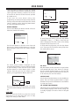
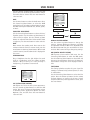
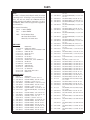
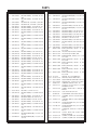
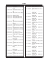
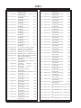
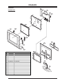
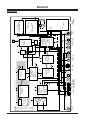
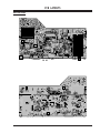
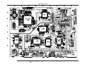
SERVICE MANUAL Model Series: L20V26 Product Type: Chassis: Manual Series: Manual Part #: Model Line: Product Year: LCD TV MF-002A CM154 923-03488 E 2002 CONTENTS Safety .......................................................... 2 Overview ...................................................... 5 Servicing ................................................... 12 Parts ......................................................... 13 Diagrams .................................................... 19 Schematic .................................................. 25 Published June 2002 by Technical Publications Zenith Electronics Corporation 201 James Record Road Huntsville, Alabama 35824-1513 Printed in U.S.A. Copyright 2002 by Zenith Electronics Corporation PRODUCT SAFETY 1. Immediately before handling any semiconductor component or semiconductor-equipped assembly, drain off any electrostatic charge on the body by touching a known earth ground. Alternatively, obtain and wear a commercially available discharging wrist strap device, which should be removed for potential shock reasons prior to applying power to the unit under test. PRODUCT SAFETY IMPORTANT SAFETY NOTICE This manual was prepared for use only by properly trained audiovisual service technicians. When servicing this product, under no circumstances should the original design be modified or altered without permission from Zenith Electronics Corporation. All components should be replaced only with types identical to those in the original circuit and their physical location, wiring, and lead dress must conform to original layout upon completion of repairs. If any fuse (or Fusible Resistor) in this TV receiver is blown, replace it only with the factory specified fuse type and rating. When replacing a high wattage resistor (Oxide Metal Film Resistor, over 1W), keep the resistor 10mm away from PCB. Always keep wires away from high voltage or high temperature parts. 2. After removing an electrical assembly equipped with ES devices, place the assembly on a conductive surface such as an ESD mat, to prevent electrostatic charge buildup or exposure of the assembly. 3. Use only a grounded-tip soldering iron to solder or unsolder ES devices. 4. Use only an anti-static solder removal device. Some solder removal devices not classified as “anti-static” can generate electrical charges sufficient to damage ES devices. Special components are also used to prevent shock and fire hazard. These components are indicated by the letter “x” included in their component designators and are required to maintain safe performance. No deviations are allowed without prior approval by Zenith Electronics Corporation. Service work should be performed only after you are thoroughly familiar with these safety checks and servicing guidelines. 5. Do not use freon-propelled chemicals. These can generate electrical charge sufficient to damage ES devices. 6. Do not remove a replacement ES device from its protective package until immediately before you are ready to install it. (Most replacement ES devices are packaged with leads electrically shorted together by conductive foam, aluminum foil, or comparable conductive material.) Circuit diagrams may occasionally differ from the actual circuit used. This way, implementation of the latest safety and performance improvement changes into the set is not delayed until the new service literature is printed. 7. Immediately before removing the protective material from the leads of a replacement ES device, touch the protective material to the chassis or circuit assembly into which the device will be installed. CAUTION: Do not attempt to modify this product in any way. Never perform customized installations without manufacturer’s approval. Unauthorized modifications will not only void the warranty, but may lead to property damage or user injury. Caution: Be sure no power is applied to the chassis or circuit, and observe all other safety precautions. 8. Minimize bodily motions when handling unpackaged replacement ES devices. (Otherwise, seemingly harmless motion, such as the brushing together of your clothing or the lifting of your foot from a carpeted floor, can generate static electricity sufficient to damage an ES device.) GENERAL GUIDANCE An lsolation Transformer should always be used during the servicing of a receiver whose chassis is not isolated from the AC power line. Use a transformer of adequate power rating to protect against personal injury from electrical shocks. It will also protect the receiver and its components from being damaged by accidental shorts of the circuitry that may be inadvertently introduced during the service operation. REGULATORY INFORMATION This equipment has been tested and found to comply with the limits for a Class B digital device, pursuant to Part 15 of the FCC Rules. These limits are designed to provide reasonable protection against harmful interference when the equipment is operated in a residential installation. This equipment generates, uses and can radiate radio frequency energy and, if not installed and used in accordance with the instruction manual, may cause harmful interference to radio communications. However, there is no guarantee that interference will not occur in a particular installation. If this equipment does cause harmful interference to radio or television reception, which can be determined by turning the equipment off and on, the user is encouraged to try to correct the interference by one or more of the following measures: Reorient or relocate the receiving antenna; Increase the separation between the equipment and receiver; Connect the equipment into an outlet on a circuit different from that to which the receiver is connected; Consult the dealer or an experienced radio/TV technician for help. Before returning the receiver to the customer, always perform an AC leakage current check on the exposed metallic parts of the cabinet, such as antennas, terminals, etc., to be sure the set is safe to operate without damage of electrical shock. LEAKAGE CURRENT COLD CHECK (ANTENNA COLD CHECK) With the instrument AC plug removed from AC source, connect an electrical jumper across the two AC plug prongs. Place the AC switch in the on position, connect one lead of ohm-meter to the AC plug prongs tied together and touch other ohm-meter lead in turn to each exposed metallic parts such as antenna terminals, phone jacks, etc. If the exposed metallic part has a return path to the chassis, the measured resistance should be between 1MΩ and 5.2MΩ. When the exposed metal has no return path to the chassis the reading must be infinite. Any other abnormality that exists must be corrected before the receiver is returned to the customer. The responsible party for this device’s compliance is: ELECTROSTATICALLY SENSITIVE DEVICES Some semiconductor (solid-state) devices can be damaged easily by static electricity. Such components commonly are called Electrostatically Sensitive (ES) Devices. Examples of typical ES devices are integrated circuits and some field-effect transistors and semiconductor “chip” components. The following techniques should be used to help reduce the incidence of component damage caused by static electricity. CM154 - 923-03488 Zenith Electronics Corporation 201 James Record Road Huntsville, AL 35824, USA Digital TV Hotline: 1-800-243-0000 2 L20V26 - SAFETY TABLE OF CONTENTS PRODUCT SAFETY ................................................ 2 TABLE OF CONTENTS ............................................ 3 OVERVIEW ........................................................ 5 WARRANTY/SERVICE ........................................ 5 FEATURES ..................................................... 5 SPECIFICATIONS ............................................. 5 REMOTE CONTROL ........................................... 6 FRONT .......................................................... 7 BACK ........................................................... 7 USER MENUS ..................................................... 8 MENU LANGUAGE ............................................ 8 CLOSED CAPTIONING ....................................... 8 PARENTAL CONTROL ........................................ 9 CHANNEL SEARCH ........................................... 9 SLEEP TIMER ............................................... 10 AUDIO SETUP .............................................. 10 VIDEO ........................................................ 11 SERVICING ...................................................... 12 ADJUSTMENTS .............................................. 12 PARTS ............................................................ 13 MODEL PARTS .............................................. 13 COMPONENT PARTS ....................................... 13 DIAGRAMS ...................................................... 19 EXPLODED VIEW ........................................... 19 BLOCK DIAGRAM .......................................... 20 MAIN PCB LAYOUT ........................................ 21 MX PCB LAYOUT ........................................... 22 TUNER PCB LAYOUT ....................................... 23 CONTROL PANEL PCB LAYOUT .......................... 23 MAIN L20V26 CIRCUIT ...................................... 25 CM154 - 923-03488 3 L20V26 - TOC -4- OVERVIEW GENERAL INFO NTSC TUNER Accepts standard United States broadcast video signals as designated by the National Television Standards Committee. HI-RES COMPONENT VIDEO Delivers the highest quality picture by breaking down video data into three separate signals—red, blue and luminance—before the data is sent to the television. WARRANTY/SERVICE This model is a Factory Service Repair model (in and out of warranty) and is covered by a one year limited warranty. For service, the end user should call 1-800984-9349 for complete shipping and handling instructions (or call 1-877-9ZENITH). Refer to the last page of the opguide for more information. SPECIFICATIONS VIDEO ENHANCEMENTS Screen Size ............................................... 20.1" Flat ............................................................. Yes Resolution Display ...................... 640 x 480 (VGA) Color Depth ..................................... 16M (8-Bit) Aspect Ratio ................................................ 4:3 Contrast Ratio ........................................... 400:1 Brightness ........................................ 450 cd/m2 High Drive Video Watts ................................ 70W Viewing Angle .................................. 140º x 120º Tuning System ........................................ NTSC-M Comb Filter ......................................... 4H Digital Digital Progressive Scan ................................. Yes Black level Exp./White Level Compression .......... Yes FEATURES 20.1" EDTV MONITOR Truly Flat LCD screen delivers razor sharp images. BUILT IN NTSC TUNER Accepts cable/antenna, HDTV, satellite dish, and NTSC video sources 640 X 480 RESOLUTION High resolution format produces extremely detailed imagery 400:1 HIGH CONTRAST RATIO LCD technology emits sharp contrast between light and dark images 450 CD/M2 HIGH BRIGHTNESS Renders an incredibly bright picture, even in light-drenched environments 140 X 120 DEGREES VIEWING ANGLE Allows for distortion-free viewing from almost any angle HI-RES COMPONENT, S-VIDEO, RF, AV INPUTS Multiple inputs for DVD players, VCRs, computers, and video game systems INNOVATIVE DESIGN Lightweight and compact frame includes built in speakers 4H DIGITAL COMB FILTER Accurately separates color data (chroma, or C) from black and white data (lumina, or Y) to produce improved color images and picture quality. EDTV Uses progressive scan technology to display noticeably higher quality images than the conventional “interlacing” method. DIGITAL PROGRESSIVE SCAN Lines of video data are processed faster and sequentially, a significant improvement on the old “interlacing” method. This allows the TV to display crisp, clear images when receiving data from a DVD player or other video sources requiring more bandwidth. CM154 - 923-03488 AUDIO ENHANCEMENTS On Screen Equalizer ........................................ Yes Gradual Volume Increase ................................. Yes Mono/Stereo/MTS/SAP ................................... Yes Bass/Treble/Balance ......................... Balance Only Total Audio (Watts) .......................... 6W (2 x 3W) Auto Volume Leveler ...................................... Yes SPECIAL FEATURES DRP (Digital Reality Processor) ........................ Yes CTI (Chrominance Transient Improvement) ........ Yes LTI (Luminance Transient Improvement) ........... Yes Tri-lingual Menus ............ English, Spanish, French Auto Programming ......................................... Yes Parental Control w/V-Chip ............................... Yes Auto Picture ................................................. Yes Auto Sleep (Power/Off) ................................... Yes Flashback ..................................................... Yes CC ............................................................... Yes CC When Mute ............................................... Yes Auto Power on and Last Source Memory ............ Yes 5 L20V26 - OVERVIEW OVERVIEW CABINET DESCRIPTION Finish .......................................... Brushed Silver Cabinet Style .............................................. New REMOTE CONTROL Transmitter ................................................... Yes Model Number ...................................... MF-002A Transmitter Finish ................................ Off-White REQUIRED APPROVALS UL, C-UL, NOM ........................... UL, C-UL, FCC (B) SERVICE/LIMITED WARRANTY Warranty: Parts/Labor ...................... 1 Year/1 Year MTBF (Approx.) .................................. 40K Hours DIMENSIONS Width x Height x Depth (Monitor)27.4" x 19" x 7.7" Weight ................................................. 30.2 lbs DIMENSIONS WITH PACKAGING Width x Height x Depth ........ 22.8" x 24.8" x 11.9" Weight ................................................ 36.4 lbs. UPC Code .................................... 4464200402 6 REMOTE CONTROL power tv/video TV/VIDEO BUTTON POWER BUTTON NUMBER BUTTONS 1 2 3 4 5 6 7 8 9 cc flashbk 0 FLASHBK BUTTON menu CAPTION BUTTON mute MUTE BUTTON MENU BUTTON ch CHANNEL BUTTONS vol mts enter ch MTS BUTTON vol sleep ENTER BUTTON VOLUME BUTTONS SLEEP BUTTON CM154 - 923-03488 6 L20V26 - OVERVIEW OVERVIEW FRONT Side Control panel Channel Buttons ch Volume Buttons vol Enter Button enter Menu Button menu tv/video TV/Video Button Remote Control Sensor Power/Standby indicator Power button on/off Illuminates brightly when the TV is in standby mode. Dims when the TV is switched on. BACK (15V) Y PB S PR ANT L IN 75Ω L DC (480i/480p) DC 12V/0.2A DVD / DTV Connection Panel Y PB PR COMPONENT(480i/480p) L R H/P S-VIDEO VIDEO MONO AUDIO R AUDIO Headphone Jack Power Input DVD/DTV Input VIDEO L AUDIO R MONITER OUT IN DVD / DTV IN CM154 - 923-03488 L ANT L IN 75Ω L DC IN (15V) Audio/Video Input S-Video Input 7 Monitor Output DCOUT 12V/0.2A Power Output Antenna Input L20V26 - OVERVIEW USER MENUS USER MENUS Press the menu button to display the available menus. Use the channel up/down buttons to select a menu option. CC 1 Text 1 CC 2 Text 2 CC 3 Text 3 CC 4 Text 4 MENU LANGUAGE Language Captions Caption/Text Parental Ctl English Off CC 1 Press the enter button to accept and exit. This TV is programmed to remember the caption/text mode it was last set when you turn the POWER off. EZ MUTE SETUP Use D E F G And And A Use the channel up/down buttons to select the Language option. Use the volume up/down buttons to select the language. Each press of volume up/down buttons changes the menu language between English, Spanish, and French. Press the enter button to exit. Captions CLOSED CAPTIONING Use OVERVIEW Closed captioning is a process which converts the audio portion of a television program into written words which then appear on the television screen in a form similar to subtitles. Closed captions allow viewers to read the dialogue and narration of television programs. Not all TV broadcasts include closed caption signals. Sometimes TV stations broadcast four different caption signals on the same channel. By selecting From CC1 to CC4, you can choose which signal you view. CC1 is usually the signal with the captions, while Another mode might show demonstration or programming information. Off And Use the CC button to select Captions. Each press of volume up/down buttons changes the caption option between off, on, or EZ Mute. EZ Mute shows the selected captions option (if available on program) when the TV sound is muted. TEXT SETUP Language Captions Caption/Text Parental Ctl Use English Off Text 1 And CAPTIONS/TEXT SETUP Language Captions Caption/Text Parental Ctl Use Text services can give a wide variety of information like captioned program lists, weather forecasts, stock exchange topics, or news for hearing impaired. But not all stations offer text services, even though they might offer captioning. In the event you are receiving a poor signal, an empty black box may appear and disappear, even when the text mode is selected. English Off CC 1 And Use the menu button to select the menu shown. Use the channel up/down buttons to select the Caption/ Text option. Each time you press the volume up/down buttons, the caption mode is cycled to the next option. CM154 - 923-03488 8 L20V26 - MENUS USER MENUS PARENTAL CONTROL Language Captions Caption/Text Parental Ctl Use be blocked by TV Rating and/or Individual Categories. Movies that have been shown at the theaters or directto-video movies use the Movie Rating System(MPAA) only. Movies Ratings: * Unblocked * G - General audience * PG - Parental guidance suggested * PG-13 - 13 years and older * R - Restricted * NC-17 - 17 years and older * X - Adult General TV Ratings: * Unblocked * TV-G - General audience * TV-PG - Parental guidance suggested * TV-14 - 14 years and older * TV-MA - Mature audience Children TV Ratings: * Unblocked * TV-Y - youth * TV-Y7 - youth, 7 years and older Content Categories: * Dialog - sexual dialogue (applies to TV-PG, TV-14) * Language - adult language (applies to TV-PG, TV14, TV-MA) * Sex scenes - sexual situations (applies to TV-PG, TV-14, TV-MA) * Violence (applies to TV-PG, TV-14 and Above, TVMA) * F Violence - fantasy violence (applies only to TVY7) * No Rating (blocks all viewing) English Off CC 1 And The Parental Control Function (V-Chip) is used to block program viewing based on the ratings sent by the broadcast station. The default setting is to allow all programs to be viewed. Viewing can be blocked by the type of program and by the categories chosen to be blocked. It is also possible to block all program viewing for a time period. To use the Parental Control Function, the following must be set. 1. Ratings and categories to be blocked. 2. Number of hours to lock the television viewing control 3. Set a password 4. Enable the lock BLOCKING SETUP Use the channel up/down buttons to select the Parental Ctl option. Press the volume down button. Age block and Content block options also have sub-menus to set the type of blocking and rating. Use the channel up/down buttons to select the types of blocking to be set. Use the volume up/down buttons to select the types of ratings to block. MPAA, Age, and/or Content block may be set. Aux. Block Sources Unblocked MPAA Unblocked Age Block Content Blk Set Hours 00 Hours Set Password To Set Lock On/Off Must Set Hours Use And CHANNEL SEARCH Press the menu button to return from the Age Block or Content Blk options. Use the channel up/down buttons to select the Set Hours option. Use the volume up/ down buttons to set the number of hours for the blocking (Up to 99). Use the channel up/down buttons to select the Set Password option. Enter a four digit password. Enter it again when requested. A new password may be chosen each time blocking is set up. Press the channel up/ down buttons to select the Lock on/off option. Press the volume up/down buttons to turn the lock On. Press the menu button to save the blocking setups and exit. AUTO PROGRAM Auto Program Manual Program Fine Use Auto programming memorizes all the channels from terrestrial TV signals or a cable TV service provider. If channels from TV and cable TV search are duplicated, press the number buttons (0 - 9) to change. V-CHIP RATINGS Most television programs and television movies can CM154 - 923-03488 And 9 L20V26 - MENUS USER MENUS Press the volume up button to begin the channel search. Wait for auto program to complete the channel search cycle before choosing a channel. The TV scans for over-the-air channels and then channels provided by a cable service. If you press the enter button during auto programming, the function will stop and only channels found up to that time will be added. When the channel search is complete, use the channel up/down buttons to review the memorized channels. Sleep Use MANUAL PROGRAM You can select Memory to add the channel or Erase to delete the channel from memory. And --- 10 240 20 180 30 120 Auto Program Manual Program Fine Use --- 90 60 To cancel sleep time setting, press the sleep button repeatedly to select [ — ]. When a sleep time you want is displayed on the screen, let the screen display disappear and the sleep time is set. To check remaining sleep time, press the sleep button once. If you turn the TV off after setting sleep timer, the setting will be erased. And Use the menu button to select the menu shown and then use the channel up/down buttons to select the Manual Program option. Press the volume up/down buttons. AUDIO SETUP MTS Balance AVL DASP Equalizer Manual Program TV 7 Memory Use And The current channel number is displayed. Use the channel up/down buttons to select a channel you want to add to memory or erase and then use the volume up/down buttons to select Memory (add) or Erase (delete). Each time you press the volume up/down buttons, you toggle between Memory and Erase. Manual Program TV 7 Memory Use AVL SETUP AVL (Auto Volume Leveler) maintains an equal volume level automatically even if the channel is changed. Use the channel up/down button to select the AVL option. Use the volume up/down button to select on or off and then press the enter button. SOUND BALANCE Use the channel up/down button to select the Balance option. Press the volume up/down button to adjust the balance and press the enter button to save. Balance is preset at 0 (center). Erase And SAP (SECOND AUDIO PROGRAM) SAP contains the secondary language signal in addition to the primary language. There are the primary and secondary languages and stereo modes in bilingual signal. Press the enter button to select and exit. The current channel is added to Memory or Erased from the channel list. SLEEP TIMER Sleep timer turns the TV off at a preset time. Use the sleep button to set sleep timer. Each press of sleep changes the setting as shown below. CM154 - 923-03488 Mono 0 Off User 10 L20V26 - MENUS USER MENUS Use the channel up/down button to select the MTS option. Each press of volume up/down buttons changes the audio mode as shown. Press the enter button to select and exit. Contrast Brightness Color Tint Sharpness APC APC DRP DASP Use the menu button to select the Audio menu. Press the channel up/down buttons to select the DASP option.Each press of volume up/down button changes the DASP sound option between User, Cinema, Sports, or Music. Use EQUALIZER ADJUSTMENTS Use the channel up/down buttons to select the User/ Equalizer option. Use the volume up/down button to select a band to adjust. Use the channel up/down buttons to adjust the band level. Select another band to adjust or press the enter button to select and exit. Optimum User Soft FINE TUNING Fine Tuning optimizes reception of a poor signal. For example, a horizontal stripe, twisted picture, no color, or weak station. Use the channel up/down buttons to select the Fine option. Press the volume up button. Use the volume up/down buttons to improve the picture (signal) reception. When the picture appearance is best, press the enter button. VIDEO 100 60 60 0 70 Clear Clear And APC (AUTO PICTURE CONTROL) APC adjusts the TV for the best picture appearance. Use the channel up/down buttons to select the APC option. Each press of volume up/down button selects a different picture appearance. Options are Clear, Optimum, User, and Soft. Press the enter button to select and exit. CM154 - 923-03488 Clear DRP (DIGITAL REALITY PICTURE) DRP improves picture outline dark areas. Use the channel up/down button to select the DRP option. Use the volume up/down buttons to select Clear and then press the enter button. Each press of volume up/ down buttons changes the screen display to Clear or Soft. HEADPHONE JACK Plug a Headphone into the jack. Adjust the sound level to a headphone using the volume up/down buttons. While listening to sound through a headphone(s), TV speakers are turned off. Use And MANUAL PICTURE CONTROL Use the volume up/down button to change the settings. Contrast, Brightness, Sharpness, and Color are adjustable from 0 to 100. Tint is adjustable from Red 50 to Green 50. Press the enter button to select and exit. APC is turned off if you change any settings. MUTE Mute removes the speaker sound. Press mute on the remote to mute the sound. To restore sound, press the mute button or volume up/down buttons. When muted sound is restored, current volume level is displayed on the screen. Contrast Brightness Color Tint Sharpness APC DRP 100 60 60 0 70 Clear Clear 11 L20V26 - MENUS SERVICING USING METHOD FOR CA-110 Use it in case of needing adjustment brightness. SERVICING ADJUSTMENTS APPLICATION OBJECT Notes (1) This set uses an adapter, so connect the adapter and the set correctly before adjustment. (2) The adjustment must be performed under the correct sequence. (3) The adjustment must be performed in the circumstance of 25 +/-5 °C and 65 +/-10% of relative humidity if there is no specific designation. (4) The input voltage of the receiver must keep 110V, 60Hz during adjustment. (5) The set must be operated for 30 minutes before adjustment. (6) Heat Run must be performed with a full white signal or TV noise signal. CA110 Screen Input signal of Video 30 [cm] LCD TV NTSC 13 CH DVCO ADJUSTMENT (1) Receive the Digital Pattern. (2) Select DVCO ADJ by pressing ADJ Key (or SVC Key) of Remote Control for Adjustment. (3) Press the VOL + Key repeatly to appear (OK). AUTO RGB ADJUSTMENT (1) Adjust RGB after performing DVCO Adjustment. (2) Receive a Digital Pattern. (3) Select AUTO RGB ADJ by pressing ADJ Key (or SVC Key) of Remote Control for Adjustment. (4) Press the VOL + Key repeatly to appear (OK). RGB LEVEL ADJUSTMENT Equipment (1) Pattern Generator (408NPS-READER) with 10 STEP if available. (2) A Remote Control for Adjustment. Adjustment (1) Select RGB LEVEL by pressing ADJ Key (or SVC Key) of Remote Control for Adjustment. (2) Select it by using VOL + Key. (3) Adjust that until 9th and 10th STEP is undistinguished by using VOL +/- Key in R-DRIVE item. (4) Adjust G-DRIVE and B-DRIVE. (5) When adjustment is finished, exit by pressing ENTER Key. CM154 - 923-03488 12 L20V26 - SERVICING PARTS PARTS This model is a Factory Service Repair model (in and out of warranty) and is covered by a one year warranty. For service, the end user should call 1-800-984-9349 for complete shipping and handling instructions (or call 1877-9ZENITH). Refer to the last page of the opguide for more information. Parts contact information: Voice: 1-888-3-ZENITH Fax: 1-888-6-ZENITH Mail: Zenith National Parts 201 James Record Road Huntsville, AL 35824-1513 MODEL PARTS LOC. 1 2 3 4 5 6 7 8 9 10 11 12 13 14 15 PART NO. 3091V00A20G 120-D44E 6871VSMA75F 5020V00553E 5020V00552H 6871VSMA74A 6304VT2011A 6633VA0003D 6871VSM814B 6871VMM644L 6871VSM812B 3809V00A10J 3550V00202A 4950V00081B 4811V00019E DESCRIPTION CABINET ASSY, ZENITH SPEAKER G705/080701A MOTORJOY 4OHM POWER PCB ASSY BUTTON SET (#39) BUTTON SET CTL PCB ASSY LCD,LC201V1-A1 20.1 INVERTER ASSY, 15VOLT KUBNKM022A MX PCB ASSY MAIN PCB ASSY TUNER PCB ASSY BACK COVER ASSY A/V COVER ABS METAL HINGE FIXER SUS304 BRACKET ASSY COMPONENT PARTS LOC. C10 C101 C102 C104 C107 C11 C1101 C1102 PART NO. 0CQ3321N509 0CE476DH618 0CQ1031N509 0CE108DD618 0CE106DK618 0CQ6831N509 0CE107DD618 0CN1030F679 C112 C12 C16 C2 C205 C209 C210 C231 C232 C238 C24 0CE475DK618 0CE227DD618 0CQ1041N509 0CQ6821N509 0CE107DF618 0CE106DF618 0CE106DF618 0CE476DF618 0CE107DF618 0CE476DF618 0CE106DF618 CM154 - 923-03488 DESCRIPTION CAP,FIXED, 0.0033UF D 100V 10% CAP,FIXED ELECTRO, 47UF STD 25V 20% CAP,FIXED, 0.01UF D 100V 10% CAP,FIXED ELECTRO, 1000UF STD 10V 20% CAP,FIXED ELECTRO, 10UF STD 50V 20% CAP,FIXED, 0.068UF D 100V 10% CAP,FIXED ELECTRO, 100UF STD 10V 20% CAP,FIXED TUBULAR(HDE), 10000PF D 16V 20% CAP,FIXED ELECTRO, 4.7UF STD 50V 20% CAP,FIXED ELECTRO, 220UF STD 10V 20% CAP,FIXED, 0.1UF D 100V 10% CAP,FIXED, 0.0068UF D 100V 10% CAP,FIXED ELECTRO, 100UF STD 16V 20% CAP,FIXED ELECTRO, 10UF STD 16V 20% CAP,FIXED ELECTRO, 10UF STD 16V 20% CAP,FIXED ELECTRO, 47UF STD 16V 20% CAP,FIXED ELECTRO, 100UF STD 16V 20% CAP,FIXED ELECTRO, 47UF STD 16V 20% CAP,FIXED ELECTRO, 10UF STD 16V 20% 13 C240 0CK224DF56A C241 0CK224DF56A C242 C244 C248 0CE226DF618 0CE107DF618 0CK224DF56A C249 0CK224DF56A C25 C250 0CE106DF618 0CK224DF56A C251 0CK224DF56A C253 0CK224DF56A C254 C255 0CE105DK618 0CK224DF56A C256 C257 0CE105DK618 0CK224DF56A C262 0CE4741K636 C263 C273 0CE224DK618 0CE4741K636 C274 0CE4741K636 C3 C312 C313 C314 C315 C320 C321 C343 C349 C359 C402 C408 0CQ6831N509 0CE107DF618 0CE107DF618 0CE107DF618 0CE107DF618 0CE107DF618 0CE107DF618 0CE476DF618 0CE106DF618 0CE107DF618 0CE476DF618 181-007H C417 C418 C419 0CE476DF618 0CE106DF618 0CE105BK618 C422 181-007H C423 C431 0CE106DF618 0CE476BK618 C435 0CE107BF618 C439 0CE477BF618 C5 0CE107BF618 C604 0CE107SF6DC C606 0CE107SF6DC CAP,FIXED CERAMIC(HDE), 220000PF 2012 16V 10% CAP,FIXED CERAMIC(HDE), 220000PF 2012 16V 10% CAP,FIXED ELECTRO, 22UF STD 16V 20% CAP,FIXED ELECTRO, 100UF STD 16V 20% CAP,FIXED CERAMIC(HDE), 220000PF 2012 16V 10% CAP,FIXED CERAMIC(HDE), 220000PF 2012 16V 10% CAP,FIXED ELECTRO, 10UF STD 16V 20% CAP,FIXED CERAMIC(HDE), 220000PF 2012 16V 10% CAP,FIXED CERAMIC(HDE), 220000PF 2012 16V 10% CAP,FIXED CERAMIC(HDE), 220000PF 2012 16V 10% CAP,FIXED ELECTRO, 1UF STD 50V 20% CAP,FIXED CERAMIC(HDE), 220000PF 2012 16V 10% CAP,FIXED ELECTRO, 1UF STD 50V 20% CAP,FIXED CERAMIC(HDE), 220000PF 2012 16V 10% CAP,FIXED ELECTRO, 0.47UF SM,SA 50V 20% CAP,FIXED ELECTRO, 0.22UF STD 50V 20% CAP,FIXED ELECTRO, 0.47UF SM,SA 50V 20% CAP,FIXED ELECTRO, 0.47UF SM,SA 50V 20% CAP,FIXED, 0.068UF D 100V 10% CAP,FIXED ELECTRO, 100UF STD 16V 20% CAP,FIXED ELECTRO, 100UF STD 16V 20% CAP,FIXED ELECTRO, 100UF STD 16V 20% CAP,FIXED ELECTRO, 100UF STD 16V 20% CAP,FIXED ELECTRO, 100UF STD 16V 20% CAP,FIXED ELECTRO, 100UF STD 16V 20% CAP,FIXED ELECTRO, 47UF STD 16V 20% CAP,FIXED ELECTRO, 10UF STD 16V 20% CAP,FIXED ELECTRO, 100UF STD 16V 20% CAP,FIXED ELECTRO, 47UF STD 16V 20% CAP,DRAWING, MPE ECQ-V1H474JL3(TR), 50V 0.47UF CAP,FIXED ELECTRO, 47UF STD 16V 20% CAP,FIXED ELECTRO, 10UF STD 16V 20% CAP,FIXED ELECTRO, 1UF KME TYPE 50V 20% CAP,DRAWING, MPE ECQ-V1H474JL3(TR), 50V 0.47UF CAP,FIXED ELECTRO, 10UF STD 16V 20% CAP,FIXED ELECTRO, 47UF KME TYPE 50V 20% CAP,FIXED ELECTRO, 100UF KME TYPE 16V 20% CAP,FIXED ELECTRO, 470UF KME TYPE 16V 20% CAP,FIXED ELECTRO, 100UF KME TYPE 16V 20% CAP,FIXED ELECTRO, 100UF MVG 16V 20% SMD CAP,FIXED ELECTRO, 100UF MVG 16V 20% SMD L20V26 - PARTS PARTS C607 C627 0CE106SH6DC 0CE107SF6DC C631 0CE107SF6DC C640 C641 C7 C801 C802 C803 0CE227SC6DC 0CE227SC6DC 0CE107DF618 0CE476DK618 0CE107DF618 0CE477BF618 C804 0CE477BF618 C805 0CE477BF618 C806 0CE477BF618 C807 0CE227BH618 C812 0CE227BH618 C814 C816 C816 C819 C820 C826 C827 0CE475DK618 0CE107DH618 0CE107DH618 0CE106DF618 0CE227DH618 0CE337DH618 0CE477BF618 C828 0CE477BF618 C871 C872 C880 0CE477DF618 0CE337DH618 0CE477BF618 C881 C882 C904 0CE107DF618 0CE227DH618 0CE476BK618 C908 0CE107BF618 C909 0CE225BK618 C910 C914 0CQ1031N509 0CE107BH618 C916 C92 C922 C926 C927 0CE107DF618 0CE105DK618 0CE106DF618 0CE107DF618 0CE107BF618 C928 0CE225BK618 C930 0CE107BF618 C932 0CK224DF56A C933 0CK224DF56A CM154 - 923-03488 CAP,AL.ELECTRO, 10UF MVG 25V M SMD R CAP,FIXED ELECTRO, 100UF MVG 16V 20% SMD CAP,FIXED ELECTRO, 100UF MVG 16V 20% SMD CAP,FIXED ELEC, 220UF MVG 6.3V M SMD CAP,FIXED ELEC, 220UF MVG 6.3V M SMD CAP,FIXED ELECTRO, 100UF STD 16V 20% CAP,FIXED ELECTRO, 47UF STD 50V 20% CAP,FIXED ELECTRO, 100UF STD 16V 20% CAP,FIXED ELECTRO, 470UF KME TYPE 16V 20% CAP,FIXED ELECTRO, 470UF KME TYPE 16V 20% CAP,FIXED ELECTRO, 470UF KME TYPE 16V 20% CAP,FIXED ELECTRO, 470UF KME TYPE 16V 20% CAP,FIXED ELECTRO, 220UF KME TYPE 25V 20% CAP,FIXED ELECTRO, 220UF KME TYPE 25V 20% CAP,FIXED ELECTRO, 4.7UF STD 50V 20% CAP,FIXED ELECTRO, 100UF STD 25V 20% CAP,FIXED ELECTRO, 100UF STD 25V 20% CAP,FIXED ELECTRO, 10UF STD 16V 20% CAP,FIXED ELECTRO, 220UF STD 25V 20% CAP,FIXED ELECTRO, 330UF STD 25V 20% CAP,FIXED ELECTRO, 470UF KME TYPE 16V 20% CAP,FIXED ELECTRO, 470UF KME TYPE 16V 20% CAP,FIXED ELECTRO, 470UF STD 16V 20% CAP,FIXED ELECTRO, 330UF STD 25V 20% CAP,FIXED ELECTRO, 470UF KME TYPE 16V 20% CAP,FIXED ELECTRO, 100UF STD 16V 20% CAP,FIXED ELECTRO, 220UF STD 25V 20% CAP,FIXED ELECTRO, 47UF KME TYPE 50V 20% CAP,FIXED ELECTRO, 100UF KME TYPE 16V 20% CAP,FIXED ELECTRO, 2.2UF KME TYPE 50V 20% CAP,FIXED, 0.01UF D 100V 10% CAP,FIXED ELECTRO, 100UF KME TYPE 25V 20% CAP,FIXED ELECTRO, 100UF STD 16V 20% CAP,FIXED ELECTRO, 1UF STD 50V 20% CAP,FIXED ELECTRO, 10UF STD 16V 20% CAP,FIXED ELECTRO, 100UF STD 16V 20% CAP,FIXED ELECTRO, 100UF KME TYPE 16V 20% CAP,FIXED ELECTRO, 2.2UF KME TYPE 50V 20% CAP,FIXED ELECTRO, 100UF KME TYPE 16V 20% CAP,FIXED CERAMIC(HDE), 220000PF 2012 16V 10% CAP,FIXED CERAMIC(HDE), 220000PF 2012 16V 10% C935 C936 0CE106DF618 0CK224DF56A C937 0CK224DF56A C938 0CK224DF56A C94 C940 0CE476DF618 0CK224DF56A C943 C944 C945 C95 C951 C954 C955 0CE335DK618 0CE106DF618 0CE477DF618 0CE105CK636 0CQ1031N509 0CE477DH618 0CE476BK618 C959 C960 D1 0CE477DH618 0CE477DH618 0DD181009AB D801 D802 D804 0DL112100AB 0DL112100AA 0DD100009AM D805 0DD181009AB D806 0DD181009AB D807 0DD181009AB D901 0DD181009AB D902 0DD181009AB DJ201 EJ201 F801 F802 IC1 IC10 380-362K 6613V00008F 0FS6300B84B 0FT2001A86B 0IZZVC0013H 0ISA721700C IC2 0IAL241610B IC201 0IIT323000D IC3 0ICTMZI001A IC301 0IHY100100A IC302 0ISM941000A IC303 6200VKR001A IC305 6200VKR001A IC4 0IFA752700A IC401 0ISO210100B IC402 0ISH092100B IC402 0ISH092100B 14 CAP,FIXED ELECTRO, 10UF STD 16V 20% CAP,FIXED CERAMIC(HDE), 220000PF 2012 16V 10% CAP,FIXED CERAMIC(HDE), 220000PF 2012 16V 10% CAP,FIXED CERAMIC(HDE), 220000PF 2012 16V 10% CAP,FIXED ELECTRO, 47UF STD 16V 20% CAP,FIXED CERAMIC(HDE), 220000PF 2012 16V 10% CAP,FIXED ELECTRO, 3.3UF STD 50V 20% CAP,FIXED ELECTRO, 10UF STD 16V 20% CAP,FIXED ELECTRO, 470UF STD 16V 20% CAP,FIXED ELECTRO, 1UF SHL,SD 50V 20% CAP,FIXED, 0.01UF D 100V 10% CAP,FIXED ELECTRO, 470UF STD 25V 20% CAP,FIXED ELECTRO, 47UF KME TYPE 50V 20% CAP,FIXED ELECTRO, 470UF STD 25V 20% CAP,FIXED ELECTRO, 470UF STD 25V 20% DIODE,SWITCHING, KDS181 TP KEC 85V,300MA LED, SM3411(DL-11S2GN1) Y-GREEN LED, SR3411(DL-11S2RN1) RED DIODE,RECTIFIERS, EU1ZV(1) 200V 0.25A 15A 0.4US DIODE,SWITCHING, KDS181 TP KEC 85V,300MA DIODE,SWITCHING, KDS181 TP KEC 85V,300MA DIODE,SWITCHING, KDS181 TP KEC 85V,300MA DIODE,SWITCHING, KDS181 TP KEC 85V,300MA DIODE,SWITCHING, KDS181 TP KEC 85V,300MA JACK,RCA, PJ 6035K PARKELEC 2P JACK ASSY, PMJ014F PARK ELEC E/ FUSE,SLOW BLOW, SLOW BLOW 630MA 250 FUSE,TIME LAG, 2000MA 125 V 8.6X4X8 IC,DRAWING, SDA555X 52PIN , ST I IC,SANYO, LA7217M MFP14 TP SYNC SEPARATOR ML-00BA IC,ATMEL, AT24C16-10PC-2.7 8PIN DIP ST EEPROM IC,ITT, VPC3230D QA B4 80P IC,CUSTOMIZED, Z8622912SSC ZILOG 18 IC,HYUNDAI, LGTV1001 64P QFP PROG. HFILTER IC,SIEMENS, SDA9410 100QFP SCAN CONV. FD-60X3R FILTER(CIRC),BAND PASS, LPF 1EA SMD H354LAI-K5206 FILTER(CIRC),BAND PASS, LPF 1EA SMD H354LAI-K5206 IC,FAIRCHILD, KA75270Z 3 TP RE-SET IC MC-007 IC,SONY, CXA2101AQ 80P,QFP VIDEO SIGNAL PROCESSOR IC,SHARP, PQ09RD21 4SIP ST REGULATOR IC,SHARP, PQ09RD21 4SIP ST REGULATOR L20V26 - PARTS PARTS IC501 0ITI808300B IC502 0IMR882840B IC505 0ISS416162B IC506 0TF492509AA IC507 0IKE702700D IC508 IC509 IC801 IC802 IC803 IC806 0ICTMMO001A 0IKE703300E 0ITC786000A 0TFVI80001A 0TFVI80001A 0TF492509AA IC807 0TF492509AA IC808 0TF492509AA IC809 0IKE781200P IC850 0ISH092100B IC851 0ISH323422A IC852 IC853 IC854 IC901 0IKE780500P 0ISH052100C 0ISH122100B 0IMCRMN002A IC902 0IKE703300E IC903 0IKE780800J IC904 0IKE780500Q IC905 0ISA428200A L1 0IFA270000A L101 6210TCE001G L102 6210TCE001G L103 0LA0272K139 L1101 0LA0222K119 L2 0IFA270000A L207 6210TCE001A L209 6210TCE001A L210 6210TCE001G L211 6210TCE001A L212 6210TCE001A L214 0LA0331K119 L215 0LA0331K119 CM154 - 923-03488 IC,TEXAS INSTRUMENT, THS8083 100QFP ADC IC PD-40X3 IC,MACRONIX, MX88L284-V 208QFP SCALE MF004A IC,SAMSUNG,K4S161622D-TC80 50 TSOP SDRAM TRANSISTOR,FETS, SI4925DY TP TEMIC 30V 6.1A IC,KEC, KIA7027AF 3, SOT-89 TP RESET IC 2.7V IC,CUSTOMIZED, SC786104DWR2 MOTOROL IC,KEC, KIA7033AF 3P SOT-89 IC,TEMIC, SI786 28SSOP TRANSISTOR,FETS, VISHAY SI4808DY TRANSISTOR,FETS, VISHAY SI4808DY TRANSISTOR,FETS, SI4925DY TP TEMIC 30V 6.1A TRANSISTOR,FETS, SI4925DY TP TEMIC 30V 6.1A TRANSISTOR,FETS, SI4925DY TP TEMIC 30V 6.1A IC,KEC, KIA7812API TO220 ST 3P 12V REGULATOR IC,SHARP, PQ09RD21 4SIP ST REGULATOR IC,SHARP, PQ3RF23 4P(TO-220) 3.3V REGUL IC,KEC, KIA78L05BP(AT) 3P 5V,150MA IC,SHARP, PQ05RD21 4SIP ST REGULATOR IC,SHARP, PQ12RD21 4SIP ST REGULATOR IC,MICRO CONTROLLER, MSP3400G QA B6 MICRO IC,KEC, KIA7033AF 3P SOT-89 IC,KEC, KIA7808API 3 ST REGULATOR IC,KEC, KIA7805API 3P TO-220 ST REGULATOR 5V(=KIA7805PI) IC,SANYO, LA4282 12S 2CHX10W AUDIO AMP IC,FAIRCHILD, 2N7000TA TO-92, LEVEL SHIFT 60V/0.2A,MC007A FILTER(CIRC),EMC, HH-1M3216-501 CERATEC 3216MM FILTER(CIRC),EMC, HH-1M3216-501 CERATEC 3216MM INDUCTOR,AXIAL LEAD, 27UH 10% A 4.0 X 10.5 INDUCTOR,AXIAL LEAD, 22UH 10% A 2.3 X 3.4 IC,FAIRCHILD, 2N7000TA TO-92, LEVEL SHIFT 60V/0.2A,MC007A FILTER(CIRC),EMC, HB-1S2012-080JT CERATEC FILTER(CIRC),EMC, HB-1S2012-080JT CERATEC FILTER(CIRC),EMC, HH-1M3216-501 CERATEC 3216MM FILTER(CIRC),EMC, HB-1S2012-080JT CERATEC FILTER(CIRC),EMC, HB-1S2012-080JT CERATEC INDUCTOR,AXIAL LEAD, 3.3UH 10% A 2.3 X 3.4 INDUCTOR,AXIAL LEAD, 3.3UH 10% A 2.3 15 L216 0LA0331K119 L217 0LA0331K119 L218 0LA0331K119 L305 6210TCE001G L306 6210TCE001G L307 6210TCE001G L308 6210TCE001G L309 6210TCE001G L310 6210TCE001G L311 6210TCE001G L312 6210TCE001A L401 6210TCE001G L402 6210TCE001G L403 6210TCE001G L511 6210TCE001A L512 6210TCE001A L519 6210TCE001E L601 6210TCE001G L602 6210TCE001G L603 6210TCE001G L801 6140VB0004B L802 6140VB0004B L803 6210TCE001G L804 6140VB0004A L805 6210TCE001G L806 6210TCE001G L807 6210TCE001G L90 6210TCE001G L901 6210TCE001G L902 6210TCE001G L903 6210TCE001G X 3.4 INDUCTOR,AXIAL LEAD, 3.3UH 10% A 2.3 X 3.4 INDUCTOR,AXIAL LEAD, 3.3UH 10% A 2.3 X 3.4 INDUCTOR,AXIAL LEAD, 3.3UH 10% A 2.3 X 3.4 FILTER(CIRC),EMC, HH-1M3216-501 CERATEC 3216MM FILTER(CIRC),EMC, HH-1M3216-501 CERATEC 3216MM FILTER(CIRC),EMC, HH-1M3216-501 CERATEC 3216MM FILTER(CIRC),EMC, HH-1M3216-501 CERATEC 3216MM FILTER(CIRC),EMC, HH-1M3216-501 CERATEC 3216MM FILTER(CIRC),EMC, HH-1M3216-501 CERATEC 3216MM FILTER(CIRC),EMC, HH-1M3216-501 CERATEC 3216MM FILTER(CIRC),EMC, HB-1S2012-080JT CERATEC FILTER(CIRC),EMC, HH-1M3216-501 CERATEC 3216MM FILTER(CIRC),EMC, HH-1M3216-501 CERATEC 3216MM FILTER(CIRC),EMC, HH-1M3216-501 CERATEC 3216MM FILTER(CIRC),EMC, HB-1S2012-080JT CERATEC FILTER(CIRC),EMC, HB-1S2012-080JT CERATEC FILTER(CIRC),EMC, HB-1M2012-800JT CERATEC 2012MM FILTER(CIRC),EMC, HH-1M3216-501 CERATEC 3216MM FILTER(CIRC),EMC, HH-1M3216-501 CERATEC 3216MM FILTER(CIRC),EMC, HH-1M3216-501 CERATEC 3216MM COIL,CHOKE, 26UH 1UEWPHY 22.5TURN YL-9N 0.4 COIL,CHOKE, 26UH 1UEWPHY 22.5TURN YL-9N 0.4 FILTER(CIRC),EMC, HH-1M3216-501 CERATEC 3216MM COIL,CHOKE, 9.5UH 1UEWPHY 13.5TURN YL-9N 0.5 FILTER(CIRC),EMC, HH-1M3216-501 CERATEC 3216MM FILTER(CIRC),EMC, HH-1M3216-501 CERATEC 3216MM FILTER(CIRC),EMC, HH-1M3216-501 CERATEC 3216MM FILTER(CIRC),EMC, HH-1M3216-501 CERATEC 3216MM FILTER(CIRC),EMC, HH-1M3216-501 CERATEC 3216MM FILTER(CIRC),EMC, HH-1M3216-501 CERATEC 3216MM FILTER(CIRC),EMC, HH-1M3216-501 CERATEC 3216MM L20V26 - PARTS PARTS L91 6210TCE001G L910 6210TCE001G LA801 6210VC0004A LA802 6210VC0004A LA803 6210VC0004A LA804 6210VC0004A LA805 6210VC0004A LA806 6210VC0004A LA811 6210VC0004A LA812 6210VC0004A LA813 6210VC0004A LA814 6210VC0004A LA815 6210VC0004A LD11010DL112100AB MJ201 6613V00004P P1 5240VE0001F P1101 6631V20014E P1103 6631V25049F PA1101 6726VV0006D PJ801 6612VAH001C PJ802 6612TAH002A Q1 0TR387500AA Q101 0TR387500AA Q103 0TR387500AA Q1101 0TR126609AA Q201 0TR387500AA Q202 0TR387500AA Q203 0TR387500AA Q205 0TR387500AA Q206 0TR387500AA Q207 0TR387500AA Q208 0TR387500AA Q209 0TR387500AA Q210 0TR387500AA CM154 - 923-03488 FILTER(CIRC),EMC, HH-1M3216-501 CERATEC 3216MM FILTER(CIRC),EMC, HH-1M3216-501 CERATEC 3216MM FILTER(CIRC),EMC,3216 4S600 TAIYOYUDEN FILTER(CIRC),EMC,3216 4S600 TAIYOYUDEN FILTER(CIRC),EMC,3216 4S600 TAIYOYUDEN FILTER(CIRC),EMC,3216 4S600 TAIYOYUDEN FILTER(CIRC),EMC,3216 4S600 TAIYOYUDEN FILTER(CIRC),EMC,3216 4S600 TAIYOYUDEN FILTER(CIRC),EMC,3216 4S600 TAIYOYUDEN FILTER(CIRC),EMC,3216 4S600 TAIYOYUDEN FILTER(CIRC),EMC,3216 4S600 TAIYOYUDEN FILTER(CIRC),EMC,3216 4S600 TAIYOYUDEN FILTER(CIRC),EMC,3216 4S600 TAIYOYUDEN LED, SM3411(DL-11S2GN1) Y-GREEN JACK ASSY, PJ6054P PARK ELEC R LEAD SET, UL 1015 AWG 22 TWI 3 CONNECTOR ASSY, 12P 300MM H-B UL 100 CONNECTOR ASSY, 4P 250MM H-B UL1007 REMOTE CONTROL RECEIVER, TSOP4838ON1 TEMIC 38.0KHZ HOLDER LESS JACK,HEADPHONE, DC-003 UNITOP 4PIN POWER JACK . JACK,HEADPHONE, DC-001 UNITOP DC-001 2.0MM (UNITOP) TRANSISTOR, BIPOLARS, CHIP 2SC3875S(ALY) TRANSISTOR, BIPOLARS, CHIP 2SC3875S(ALY) TRANSISTOR,BIPOLARS, CHIP 2SC3875S(ALY) TRANSISTOR,BIPOLARS, KTA TP KEC - 1266-Y (KTA1015) TRANSISTOR,BIPOLARS, CHIP 2SC3875S(ALY) TRANSISTOR,BIPOLARS, CHIP 2SC3875S(ALY) TRANSISTOR,BIPOLARS, CHIP 2SC3875S(ALY) TRANSISTOR,BIPOLARS, CHIP 2SC3875S(ALY) TRANSISTOR,BIPOLARS, CHIP 2SC3875S(ALY) TRANSISTOR,BIPOLARS, CHIP 2SC3875S(ALY) TRANSISTOR,BIPOLARS, CHIP 2SC3875S(ALY) TRANSISTOR,BIPOLARS, CHIP 2SC3875S(ALY) TRANSISTOR,BIPOLARS, CHIP 2SC3875S(ALY) Q211 0TR387500AA Q212 0TR387500AA Q213 0TR387500AA Q214 0TR150400BA Q214 0TR150400BA Q215 0TR387500AA Q216 0TR387500AA Q3 0TR387500AA Q301 0TR150400BA Q302 0TR150400BA Q303 0TR150400BA Q304 0TR150400BA Q305 0TR150400BA Q306 0TR150400BA Q401 0TR150400BA Q402 0TR150400BA Q403 0TR150400BA Q404 0TR387500AA Q460 0TR387500AA Q50 0TR387500AA Q501 0TR387500AA Q801 0TR387500AA Q90 0TR387500AA Q901 0TR150400BA Q902 0TR150400BA Q903 0TR150400BA R1101 0RD4701F609 R1102 0RD3300F609 R1104 0RD1201F609 R1107 0RD4701F609 R1108 0RD4701F609 R1109 0RD4701F609 16 TRANSISTOR,BIPOLARS, CHIP 2SC3875S(ALY) TRANSISTOR,BIPOLARS, CHIP 2SC3875S(ALY) TRANSISTOR,BIPOLARS, CHIP 2SC3875S(ALY) TRANSISTOR,BIPOLARS, CHIP 2SA1504S(ASY) TRANSISTOR,BIPOLARS, CHIP 2SA1504S(ASY) TRANSISTOR,BIPOLARS, CHIP 2SC3875S(ALY) TRANSISTOR,BIPOLARS, CHIP 2SC3875S(ALY) TRANSISTOR,BIPOLARS, CHIP 2SC3875S(ALY) TRANSISTOR,BIPOLARS, CHIP 2SA1504S(ASY) TRANSISTOR,BIPOLARS, CHIP 2SA1504S(ASY) TRANSISTOR,BIPOLARS, CHIP 2SA1504S(ASY) TRANSISTOR,BIPOLARS, CHIP 2SA1504S(ASY) TRANSISTOR,BIPOLARS, CHIP 2SA1504S(ASY) TRANSISTOR,BIPOLARS, CHIP 2SA1504S(ASY) TRANSISTOR,BIPOLARS, CHIP 2SA1504S(ASY) TRANSISTOR,BIPOLARS, CHIP 2SA1504S(ASY) TRANSISTOR,BIPOLARS, CHIP 2SA1504S(ASY) TRANSISTOR,BIPOLARS, CHIP 2SC3875S(ALY) TRANSISTOR,BIPOLARS, CHIP 2SC3875S(ALY) TRANSISTOR,BIPOLARS, CHIP 2SC3875S(ALY) TRANSISTOR,BIPOLARS, CHIP 2SC3875S(ALY) TRANSISTOR,BIPOLARS, CHIP 2SC3875S(ALY) TRANSISTOR,BIPOLARS, CHIP 2SC3875S(ALY) TRANSISTOR,BIPOLARS, CHIP 2SA1504S(ASY) TRANSISTOR,BIPOLARS, CHIP 2SA1504S(ASY) TRANSISTOR,BIPOLARS, CHIP 2SA1504S(ASY) RESISTOR,CARBON FILM, 4.7KOHM 1/6W 5% RESISTOR,CARBON FILM, 330 OHM 1/6 W 5% RESISTOR,CARBON FILM, 1.2K OHM 1/6 W 5% RESISTOR,CARBON FILM, 4.7KOHM 1/6W 5% RESISTOR,CARBON FILM, 4.7KOHM 1/6W 5% RESISTOR,CARBON FILM, 4.7KOHM 1/6W L20V26 - PARTS PARTS R1110 0RD4701F609 R250 0RD1200H609 R253 0RD1200H609 R321 0RN2202F409 R322 0RN5602F409 R803 0RHZVTA001A R804 0RHZVTA001A R880 0RHZVTA001A R932 0RF0561K607 RA501 0RRZVTA001A RA502 0RRZVTA001A RA503 0RRZVTA001A RA504 0RRZVTA001A RA505 0RRZVTA001A RA506 0RRZVTA001A RA507 6210VC0004A SJ201 6612VJH008D SW1101 SW1101 SW1102 SW1103 SW1104 SW1105 SW1106 SW1107 SY302 6200VKR001B SY525 6210VC0004A SY526 6210VC0004A SY527 6210VC0004A SY532 6210VC0004A T801 6170VTCA30A TU301 6700VNF019C CM154 - 923-03488 5% RESISTOR,CARBON FILM, 4.7KOHM 1/6W 5% RESISTOR,CARBON FILM, 120 OHM 1/2 W 5% RESISTOR,CARBON FILM, 120 OHM 1/2 W 5% RESISTOR,FIXED METAL FILM, 22K OHM 1/ 6 W 1.00% TA52 RESISTOR,FIXED METAL FILM, 56K OHM 1/ 6 W 1.00% TA52 RESISTOR,DRAWING, 0.025 OHM 1W 2% 2512, IRC RESISTOR,DRAWING, 0.025 OHM 1W 2% 2512, IRC RESISTOR,DRAWING, 0.025 OHM 1W 2% 2512, IRC RESISTOR,DRAWING, 5.6 OHM 2 W 5.00% TA62 RESISTOR,DRAWING, MNR-14-E0A-J-101 100OHM 5% RESISTOR,DRAWING, MNR-14-E0A-J-101 100OHM 5% RESISTOR,DRAWING, MNR-14-E0A-J-101 100OHM 5% RESISTOR,DRAWING, MNR-14-E0A-J-101 100OHM 5% RESISTOR,DRAWING, MNR-14-E0A-J-101 100OHM 5% RESISTOR,DRAWING, MNR-14-E0A-J-101 100OHM 5% FILTER(CIRC),EMC,3216 4S600 TAIYOYUDEN JACK,RCA, PJ6063D PARKELEC DVD 140-313A SWITCH,TACT, TACT 2LEAD 100G(TA) 6600VM1001A SWITCH,PUSH, SDKLA1 ALPS UL/CSA 250V 5A 140-313A SWITCH,TACT, TACT 2LEAD 100G(TA) 140-313A SWITCH,TACT, TACT 2LEAD 100G(TA) 140-313A SWITCH,TACT, TACT 2LEAD 100G(TA) 140-313A SWITCH,TACT, TACT 2LEAD 100G(TA) 140-313A SWITCH,TACT, TACT 2LEAD 100G(TA) 140-313A SWITCH,TACT, TACT 2LEAD 100G(TA) FILTER(CIRC),BAND PASS, LPF 2EA SMD TH355LSK-K5214 FILTER(CIRC),EMC,3216 4S600 TAIYOYUDEN FILTER(CIRC),EMC,3216 4S600 TAIYOYUDEN FILTER(CIRC),EMC,3216 4S600 TAIYOYUDEN FILTER(CIRC),EMC,3216 4S600 TAIYOYUDEN TRANSFORMER,CONV.[COIL], EPC 13-Z 320UH DC-DC CONV. SI-786 (NF-99LA) TUNER, TAFC-H101P LG PRECISION CO., LTD X1 156-A01L X1 156-A01L X301 156-A02X X302 6202VDB007B X501 6202VDT002B X601 6202VDT002B X90 166-E02F X901 156-A02M ZD101 0DZ330009BA 17 NTSC PHONO 45.75M RESONATOR,CRYSTAL, HC49U 6.000MHZ 30PPM 16PF RESONATOR,CRYSTAL, HC49U 6.000MHZ 30PPM 16PF RESONATOR,CRYSTAL, HC49U 27.000MHZ 25PPM 20PF RESONATOR,CRYSTAL, HC49U 20.250MHZ 30PPM 16PF RESONATOR,CRYSTAL, SX-1SMD 14.318MHZ 30PPM 16PF TP RESONATOR,CRYSTAL, SX-1SMD 14.318MHZ 30PPM 16PF TP RESONATOR,CERAMIC, CSB500F9 MURATA 500KHZ . RESONATOR,CRYSTAL, HC49U KJE RADIAL 18.432MHZ 30PPM 10PF DIODE,ZENERS, ZENER HZT33 TAPING L20V26 - PARTS - 18 - DIAGRAMS DIAGRAMS 8 EXPLODED VIEW 9 10 11 7 1 2 6 13 12 5 3 4 L20V26 Model Parts No. PART NO. DESCRIPTION 1 3091V00A20G CABINET ASSY, ZENITH 2 120-D44E 3 6871VSMA75F POWER PCB ASSY 4 5020V00553E BUTTON SET (#39) 5 5020V00552H BUTTON SET 6 6871VSMA74A CTL PCB ASSY SPEAKER G705/080701A MOTORJOY 4OHM 7 6304VT2011A 8 6633VA0003D INVERTER ASSY, 15VOLT KUBNKM022A 14 LCD,LC201V1-A1 20.1 9 6871VSM814B MX PCB ASSY 10 6871VMM644L MAIN PCB ASSY 11 6871VSM812B TUNER PCB ASSY 12 3809V00A10J BACK COVER ASSY 13 3550V00202A A/V COVER ABS 14 4950V00081B METAL HINGE FIXER SUS304 15 4811V00019E BRACKET ASSY CM154 - 923-03488 15 19 L20V26 - DIAGRAMS DC Output (12V) L C 2 0 1 V 1 A 3 PC Input Dual Audio AMP LA4282 15V 8 /8 /8bit R/G/B VIDEO RAM 2M 3.3V 5.0V 20 PB SCART JACK Y Y/U/V in R/G/B 24 SCL/SDA RESET 4.2V L PR DVD/DTV Input (480I/480P) R/G/B/FBRinL/ TV/L/R out Audio Processor MSP-34XX RF : 2, SCART : 4 MONO : 1 I2S : 2 ------18.432MHz--L-SPK/WOOFER H/P, I2S SCART OUT : 2 8.0V SCALER(Format Converter) MX88L-284FC-V 14.318MHz 3.3V 5V(FOR RESET IC 3,3V) Analog R/G/B/H/V 3.3V Y/U/V (480P) 0.5-0.7 R H/P IC302 SCAN Converter SDA-9410 27.0MHz Y/U/V (480P) Input S- .... SCL/SDA 4:2:2 Y/U/V SCL/SDA SCL/SDA Multi-Component Processor(BBVSP) CXA 2101AQ YCrCb : 2 / 4 RGB : 4 / 2 OUT RGB :1, TUV : 1 9V AD Converter THS8083 3.3V 4:2:2 Y/U/V CLK H-sync CAPTION R/G/B L V VIDEO Input R . VIDEO H/V Caption Processor 5V SCART(R/G/B/FB) YUV IN(VIN4 : H-CHECK)480I S-VHS(VIN1 : Y/C)) A/V2(VIN2 : CVBS) IC301 H- FILTER (DRP Processor) LGTV-1001 3.3V R/G/B OSD H/V (2H) SCL/SDA CM154 - 923-03488 SCL/SDA SCL1/SDA1 R L V VIDEO Output X2 15V M/O(CVBS) RF(VIN3 : CVBS) 3.3V IF AGC SIF SCL SDA CVBS 5V 30V 15V Input ANT (RF) TUNER TUNER TO MICOM POWER-ON/OFF TO MICOM DC to AC INVEERTER 15V POWER DC to DC Converter (SI786,SI4808DY,T801) BRI-ADJ 33V 3.3V 5V DCInput (12V) . COMB/FIL : 4H INPUT . 4 CVBS . 1 S-VHS YCrCb . 2 RGB/ . 1 F/B . 1 CVBS OUTPUT /Cb OUTPUT . Y/Cr 20.25 MHz IC201 Color Decoder/ A/D Converter VPC-3230D 5V H-Sync. SEP 480 I/P ÆÇ´Ü IC1 MICOM / TXT 6.0MHz 3.3V EEP EEP ROM ROM SCL/SDA LCD PANNEL L-SPK R-SPK DIAGRAMS BLOCK DIAGRAM L20V26 - DIAGRAMS PCB LAYOUTS MAIN PCB LAYOUT CM154 - 923-03488 21 L20V26 - PCBS PCB LAYOUTS MX PCB LAYOUT CM154 - 923-03488 22 L20V26 - PCBS PCB LAYOUTS TUNER PCB LAYOUT TUNER(TOP) TUNER(BOTTOM) CONTROL PANEL PCB LAYOUT POWER CONTROL CM154 - 923-03488 23 L20V26 - PCBS - 24 - Main L20V26 Circuit 1 2 3 4 5 6 7 8 9 10 G F E D C B A CM154 - 923-03488 CRITICAL SAFETY COMPONENTS ARE IDENTIFIED BY THE SYMBOL REPLACE ONLY WITH PART NUMBERS SPECIFIED. . 25 NOTE: WAVEFORMS AND VOLTAGES WERE MEASURED AT 120VAC, CHANNEL 5, AND NSTC COLOR BARS. L20V26 SHEET 25