1
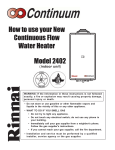
INSTALLER'S INSTALLATION INSTRUCTIONS
-Warnings-
REF DESCRIPTION
This manual must be followed exactly.
Maintain proper space around the unit for proper servicing and operation.
Minimum clearances from combustible materials are listed below.
Top of Heater
Back of Heater
Front of Heater
Sides of Heater
Ground
12 inches
0 inch
24 inches
6 inches
12 inches
**1 foot
1 foot
3 feet
6 feet
*
7 feet
Clearance to nonmechanical air supply inlet to building or the
combustion air inlet to any other appliance
K
Clearance to a forced air inlet into a building
L
Clearance above paved sidewalk or paved driveway located on
public property
M
Clearance under deck, veranda, porch, or balcony
(open on 3 sides)
3 feet
3 feet
N
Vent FIue from wall (FIat or Pitched Roof)
2 feet
2 feet
O
Vertical between two terminals on the same wall above each
other
5 feet
5 feet
P
Clearance between two vertical flue on the same pIane
1 foot
1 foot
Q
Horizontal between two terminals on the same wall
1 foot
1 foot
R
Clearance between two Vertical flue on pitched roof above
each other
5 feet
5 feet
S
Clearance from terminal facing a terminal
4 feet
4 feet
* For clearances not specified in ANSI Z223.1 / NFPA 54 or CAN/CGAB149, please use clearances in accordance with local installation codes
and the requirement of the gas supplier.
** 4 feet for Other than Direct-Vent Appliance.
Minimum clearances from non-combustible materials are listed below.
Top of Heater
Back of Heater
Front of Heater
Sides of Heater
Bottom
Candadian
Installations
J
The Rinnai Water Heater is not suitable for use in pool or spa applications.
Installer must install a Pressure relief valve. Pipe pressure relief discharge to
a drain or outside environment.
U.S. Installations
2 inches
0 inch
24 inches
1/2 inches
2 inches
Suggested temperatures are:
Kitchen 120°F - 130°F, Shower 98°F - 110°F, Bath fill 102°F - 114°F
These temperatures are suggestions only. You may find higher or lower
temperatures more comfortable. Maintaining lower temperatures helps
save energy. To obtain water temperatures lower than 98°F, simply add
cold water.
Deluxe Controllers are an optional extra. ‘Controller’ and ‘Deluxe’
Controllers can be installed together. Controllers allow temperature
selection only. ‘Deluxe’ Controllers have temperature selection, bath fill and
clock functions.
Controllers allow the water temperature to be set from the various
locations where they are installed. The temperature selected will be
available to all outlets. Below are the combination of Controllers that are
offered by Rinnai:
REMOTE CONTROL
CONNECTION TERMINALS
REMOTE CONTROL
CABLE
CABLE
CLAMP
10) Thread the cable through the access hole at the base of the unit and
connect the wires to the controller terminals on the right hand side
bottom of the PCB.
11) Secure the controller cable using the clamp provided.
12) Replace plastic cover over PCB and then replace the cover of the
Rinnai.
Controllers Combination Pattern
Remote and Deluxe Controllers
REMOTE CONTROLLER OPERATION
INSTALLER'S INSTALLATION INSTRUCTIONS
Remote Controllers- General
Before installing the remote controllers, determine the most convenient
location(s).
When deciding on the best location for the remote controllers, please
consider the
following items:
1) Place the controllers out of reach of small children.
2) Avoid locations where the controller(s) will become hot. (over the stove,
near the oven or a radiant heater.
3) Avoid direct sunlight. (The digital monitor can be difficult to read in
direct sunlight)
4) Avoid areas where the remote can be splashed with cooking water, oil
or sauce.
5) The remote controller cables carry low voltage, 12VDC digital.
Digital Monitor
Indicates the selected
water temperature.
Error messages flash
in the event of a failure.
INSTALLER'S INSTALLATION INSTRUCTIONS
Remote Controllers - Installation
1) Determine a suitable location for the
controller.
2) Make three holes on the wall as
shown.
3) Run the cable between the controller
and the Rinnai Water Heater or the
controller and the other controller.
INSTALLER'S INSTALLATION INSTRUCTIONS
Locating the vent terminal
U.S. Installations
Canadian
Installations
1 foot
1 foot
**1 foot
1 foot
*
*
B
Clearance to window or door that may be opened
C
Clearance to permanently closed window
D
Vertical clearance to ventilated soffit, eaves or overhang
3 feet
3 feet
E
Clearance to unventilated soffit, eaves or overhang
3 feet
3 feet
F
Clearance to outside corner
1 foot
1 foot
G
CIearance to inside corner
2 feet
2 feet
H
Clearance to each side of center line extended above
meter/regulator assembly
*
3 feet within a height
15 feet. above the
meter/reguIator
assembly
Clearance to service regulator vent outlet
*
Thermostat
Increases or decreases
the desired water
temperature.
3 feet
COLD water inlet filter
inlet GAS test port
IMPORTANT: Set dip switches 7 and 8 on the bottom (SW1) to ‘OFF’
to return the appliance to 'Normal' combustion. (Fig. 6).
15. Close hot water tap.
16. Turn ‘OFF’ the gas supply and 120V power supply.
17. Remove pressure gauge & replacing sealing screw.
18. Turn ‘ON’ the gas supply and 120V power supply.
19. Operate unit and check for gas leaks at test point.
20. Replace the front cover of the appliance.
GAS
THIS APPLIANCE MUST BE INSTALLED, SERVICED
AND REMOVED BY AN AUTHORISED PERSON
DURING PRESSURE TESTING OF THE CONSUMER PIPING
ENSURE GAS COCK SITUATED BEFORE UNIT IS SHUT-OFF.
FAILURE TO DO SO MAY RESULT IN SERIOUS
DAMAGE TO THE APPLIANCE AND POSSIBLE INJURY.
Table 1.
REU-V2532W
REU-V2532WC
REU-V2526W
150PSI
Prop.G
Nat.G
Prop.G
MC-91-1US
+
MC-91-1US
+
MC-91-1US
+
4
MC-91-1US
+
MC-91-1US
+
MC-91-1US
+
5
MC-91-1US
+
BC-100V
+
MC-100V
+
6
MC-91-1US
+
MC-91-1US
+
BC-100V
+
+
**MC-91-1US
MC-100V
Fig. 1
Forced High
Nat.G
model
Fig. 2
COMMISSIONING
ON
GAS PRESSURE SETTING
108
110
112
114
116
118
120
Approx.
temperature (°C)
37
38
39
40
41
42
43
44
46
47
48
49
□ Instructed the customer how to operate the Controllers.
□ Verify proper clearances around the unit and all vents and air intakes.
(See owner's manual for all clearance requirements.)
□ Explained to the customer to never store anything around the vent
terminals or block the air and/or exhaust ports to the unit.
98 100 102 104 106 108 110 115 120 125 130 135 140
98 100 102 104 106 108 110 115 120 125 130 135 140 150 160 185
Approx.
temperature(°C)
37
38
39
40
41
42
43
46
49
52
54
57
60
For Internal models only
66
71
□ Ensure you used the proper venting materials for the unit you have
installed.
85
(QS) Water Flow Sensor:
Black ~ Red
11 ~ 13 VDC
Yellow ~ Black
4 ~ 7 VDC
WARNING
In appropriate Dip Switch setting can damage the Rinnai water heater and
may void the warranty of this unit
SW1
ON
ON
Fig. 5
Fig. 6
The settings below are factory default settings. Please ensure the model
number and gas type of the unit you have, matches the model number
and gas type listed below; before settings any switches. If you need
assistance, contact Rinnai at (800)621-9419 before proceeding.
5.5K ~ 6.2K
1 meg ~ 1.4 meg
B4
B4
5~6
1~5
G4 ~ G5
G2 ~ G5
G1 ~ G5
G3 ~ G5
4~5
2~5
1~5
3~5
By-pass Flow Control: (REU-V2532W/WC ONLY)
Code
Displayed
Fault
00
When checking maintenance code history,
“00” is substituted for “LC”
02
No burner operation during freeze
protection mode
03
Power interruption during Water Smart/Bath Fill
(Hot water will not flow when power returns)
10
Air intake supply or exhaust blockage
11
No Ignition
12
Flame Failure, poor ground connection
14
Thermal Fuse
16
Over Temperature Warning
32
Outlet water temperature sensor reading
out of expected range
33
Heat exchanger outlet water temperature
faulty
52
Modulating Solenoid Valve signal abnormal
61
Combustion Fan Failure
65
Water Flow Servo Faulty
(Does not stop flow properly)
71
SV0, SV1, SV2 or SV3
Solenoid Valve Circuit Faulty
72
Flame Sensing Device Faulty
LC
Scale build-up in Heat Exchanger
Nothing happens when water
flows through water heater.
Brown ~ White
2 ~ 6 VDC
Orange ~ White
Yellow ~ White
Red ~ White/ Ground
Items to Inspect
Build up of lime scale in heat exchanger - needs to be
flushed.
Verify that gas supply is turned on to the water heater and
valve at meter or tank is open. Verify proper gas type and
supply pressure. Bleed air from gas line. Verify all ignition
component/wires are connected.
Unit in operating
mode
15 ~ 35K
(IG) Ignition System:
Grey ~ Grey
90 ~ 100 VAC
N/A
A1
1~2
(FM) Combustion Fan Motor:
Red ~ Black
6 ~ 45 VDC
N/A
A1
1~2
White ~ Black
5 ~ 10 VDC
9.2K ~ 9.4K
A1
2~4
Yellow ~ Black
11 ~ 13 VDC
3.5K ~ 3.9K
A1
2~3
Set your meter to the hertz scale. Reading across the red and yellow wires at terminals 2 and 3
you should read between 60 and 350 hertz.
Thermal Fuse:
Red ~ Red
12 VDC
Below 1 ohm
B~C
B6 ~ C1
Turn off all hot water taps. Press ON/OFF twice.
Check for a restriction in exhaust or intake vent, verify proper
dip switch settings. Ensure only Rinnai approved venting
components are used.
Verify that gas supply is turned on to the water heater and at
meter or tank. Verify proper gas type and supply pressure.
Bleed air from gas line. Verify all ignition component/wires
are connected.
Make sure gas is turned on at the water heater; check for
obstructions in exhaust vent. Ensure only Rinnai approved
venting components are used. Verify proper grounding.
Check for debris or moisture in burner area.
Ensure high and low fire manifold gas pressures are properly
set. Verify dip switch settings are correct. Measure
resistance in ohms of safety circuit.
Verify dip switch settings, check manifold pressure and verify
gas type for water heater. Check for clogged heat
exchanger. Check for low water flow in a circulating system
causing short-cycling.
Check outlet temperature sensor or wiring for damage.
Measure resistance of sensor. Clean sensor of scale build up.
Check H.E. outlet sensor or wiring. Measure resistance of
sensor. Clean sensor of scale build-up
Check gas control wiring harness and measure resistance of
valve coil in ohms.
Combustion fan or wiring harness faulty. Make sure
motor/fan turns freely. Measure resistance of motor winding.
Water Flow Servo or wiring faulty. Check Water Flow Servo
wiring harness conection.
Measure resistance of Water Flow Servo wiring.
Check all gas solenoid wiring harness and connections.
Measure resistance of each solenoid valve coil.
Check flame rod and wiring harness connections. Measure
micro amp output of sensor circuit with flame present. Clean
flame sensor of any build-up. Check for debris in burner
chamber that may block flame from sensor.
Build up of lime scale in heat exchanger ñ needs to be
flushed.
Clean inlet filter screen and ensure you have at least the
minimum flow rate required to fire unit. Check for pipe dope
inside water flow control turbine.
On new installations, ensure hot and cold water lines are not
crossed.
Check for bleed over. Isolate unit from building by turning off
hot water line to building. Then open your pressure relief
valve, if unit fires, thereís a bleed over in your plumbing.
If a circulating system is in use, it must be isolated also.
Overheat Switch:
Red ~ Red
12 VDC
Below 1 ohm
B~C
B6 ~ C1
Flame Rod:
Place one lead of your meter to the flame rod and the other to earth or ground. With the unit
running you should read between 5 ~ 150 VAC. Set your meter to the µ amp scale, series your
meter in line with the flame rod. You should read 1µ or greater for proper flame circuit. In the
event of low flame circuit remove the flame rod and check for carbon and/or damage.
Heat Exchanger, Air Temperature, and Outgoing Water Temperature Thermistors:
Check all thermistors by inserting meter leads into each end of the thermistor plug. Set your
meter to the 20K scale and read resistance. You should be able to apply heat to the thermistor
bulb and see the resistance decrease. Then apply some ice to the thermistor and the resistance
should increase. See below for examples of temperatures and resistance reading at those
temperatures.
Example: 59°F = 11.4 ~ 14K
86°F = 6.4 ~ 7.8K
113°F = 3.6 ~ 4.5K
140°F = 2.2 ~ 2.7K
221°F = 0.6 ~ 0.8K
Outgoing Water Thermistor:
White ~ White
N/A
See example above B
Heat Exchanger Temperature Thermistor:
White ~ White
N/A
See example above B
B3 ~ B4
B3 ~ B12
Surge Protector:
Black ~ White
108 ~ 132 VAC
N/A
Surge Protector D1 1 ~ 3
Blue ~ Brown
108 ~ 132 VAC
N/A
Surge Protector D2 1 ~ 2
With the power off you can check the continuity through the surge protector. Place one meter
lead on the top pin #1 of the surge protector and pin #2 on the bottom of the surge protector.
Then check across top pin #3 and bottom pin #1, if you read continuity across these two points
the surge protector is good. If you do not get continuity, replace the surge protector.
Remote control does not light up but you have 12 VDC at the
terminals for controls:
Disconnect water flow control motor, then turn on hot water,
if unit fires replace water flow control assembly.
Remote Controls:
Terminals D1
SERVICEMAN'S TROUBLESHOOTING INFORMATION
for the RINNAI WATER HEATERS
Rinnai Water Heaters
Dip Switch Default Settings
10 ~ 13 VDC digital 1.5K ~ 1.9K ohms
H
1~3
IMPORTANT SAFETY NOTES:
There are a number of (live) tests that are required when fault finding this
product. Extreme care should be used at all times to avoid contact with
energized components inside the water heater. Only trained and qualified
service agencies should attempt to repair this product. Remember,
before checking for resistance readings, you should disconnect the power
source to the unit and isolate item the to be checked from the circuit (unplug it).
Frost Protection:
This unit has four frost protection heaters mounted at different points inside the unit, to protect
the water heater from freeze ups. There are two heaters located on the outlet hot water line
next to the thermistor.
Using a voltage meter set on the 200 ohm scale, you should have a resistance reading of 26 ~
30 ohms through each of these heaters. The heater located on the heat exchanger piping
should have a resistance reading of 81 ~ 86 ohms and the one located in the water flow sensor
valve has a resistance reading of 16 ~ 19 ohms. Voltage throughout this circuit should be 120
VAC.
(TR) Transformer:
Wire color
Black ~ White
Blue ~ Brown
Amp Fuses:
This unit has two inline (3) amp glass fuses. Remove the fuse and check continuity through it. If
you have Continuity through the fuse, it is good. If you can not read continuity, the fuse is blown
and must be replaced.
Voltage
90 ~ 100 VAC
108 ~ 132 VAC
Resistance
51 ~ 63 ohms
51 ~ 63 ohms
Connector #
F9
F7
Pin #'s
1~2
1~3
(SV1, SV2, SV3 and POV) Gas valve and Modulating solenoids: (Set meter above 2K)
(Main) Pink ~ Black 80 ~ 100 VDC
1.7K ~ 2K ohms
E1
1~2
(SV1) Black ~ Yellow 80 ~ 100 VDC
1.7K ~ 2K ohms
E2
2~3
(SV2) Black ~ Blue 80 ~ 100 VDC
1.7K ~ 2K ohms
E3
2~4
(SV3) Black ~ Brown 80 ~ 100 VDC
1.7K ~ 2K ohms
E4
2~5
(POV) Pink ~ Pink
2 ~ 15 VDC
67 ~ 81 ohms
C2
3~4
(M) Water Flow Control Device Servo or Geared Motor:
Red ~ Blue
11 ~ 13 VDC
22 ~ 26 ohms
B2
9 ~ 10
Grey ~ Brown
4 ~ 6 VDC
N/A
B2
5~7
Grey ~ Yellow
N/A
N/A
B2
5~8
Grey ~ Orange
11 ~ 14 VDC
N/A
B2
5~6
NOTE: The grey wire listed above turns to black at B connector on the PCB, the orange wire turns to red.
3
106
□ Gas supply pipe is purged of foreign material before connection.
REU-V2532WC(°F)
Fig. 4
SW1
5. Attach pressure gauge to burner test point, located on the gas control.
(Fig.2).
6. Turn ‘ON’ the gas supply.
7. Turn ‘ON’ 120V power supply.
8. If remote controllers are fitted, turn the unit ‘ON’ at the kitchen controller,
select the maximum delivery temperature and open all available hot
water taps full including the shower.
(CAUTION: Ensure building occupants do not have access to hot water
outlets during this procedure).
104
□ Proper gas type and pressure is supplied to the unit. (See owner's
manual for correct inlet gas pressures in the specification section.
Normal inlet gas pressures are 7" to 10" of water column for natural
gas, and 11" to 13" of water column for propane gas).
temperature
Regulator adjustment
screw access plug
Fig. 3
Note: ‘ON’ towards front, ‘OFF’ towards rear.
102
□ Gas supply system is properly sized. All gas meters, regulators, gas
line types, tanks, etc. have a BTU value. Please confirm that all
components meet the gas requirements at this location. Verify the
system is functioning correctly by connecting your manometer to the
gas pressure test port on the Rinnai unit. Operate all gas appliances in
the facility. The inlet gas pressure must not drop below that listed in the
ownerís manual specification sheet or appliance rating plate.
REU-V2526W(°F)
REU-V2532W
No code or
blank
display
1. Turn ‘OFF’ the gas supply.
2. Turn ‘OFF’ 120V power supply.
3. Remove the front cover from the appliance.
4. Check gas type switches (Fig.1) are in the correct position
(dip switch 1 of SW2 ‘ON’ = NG, ‘OFF’ = LPG)
100
□ Proper model controllers are used, connected and functioning.
6"W.C. 10"W.C.
0.56"W.C. 0.88"W.C. 3.4"W.C. 5.1"W.C.
10.5"W.C. 13.5"W.C.
(Ensure gas pressure check under Commissioning above has been
completed first !)
The regulator is electronically controlled and factory pre-set. Under
normal circumstances it does not require adjustment during
installation. Make adjustments only if the unit is not operating
correctly and all other possible causes for incorrect operation have
been eliminated.
98
□ 120 VOLTS A.C. is connected to the unit, it is properly GROUNDED
and circuit is turned on.
Temperature controllers allows precise temperature control by the user.
When used correctly, the hot water unit will deliver the selected
temperature, even when the water flow is varied, or more than one tap is in
use. Each Temperature Controller can be individually programmed,
however the water heater unit can only deliver one set temperature at any
time. The available temperatures (°F) are as follows:
Temperature Table by Models
Prop.G
With all gas appliances in operation at maximum gas rate, the flowing
inlet pressure at the incoming test point on the Rinnai Water Heaters
should read 6"W.C. - 10.5"W.C. on Natural Gas and 10"W.C. - 13.5"W.C.
on Propane Gas. If the pressure is lower, the gas supply is inadequate
and the appliance unit will not operate to specification. Check gas meter,
regulator and pipework for correct operation/sizing and rectify as
required.
water smart/
bath fill temperature (°F)
□ A pressure relief valve is installed and is rated for 200,000 Btu's at 150
PSI per local code.
GENERAL CONTROLLER INFORMATION
APPLIANCE OPERATING PRESSURES
Nat.G
3
□ You have installed isolating valves, unions, and drain down vales on the
cold water inlet line and hot water outlet lines. (These components are
used for servicing and/or removing the appliance quickly).
MUTE
To eliminate the beeping sound, press and hold □
▲ and ▼
□ button
simultaneously until a ‘beep’ is heard (approximately 5 seconds).
Burner test point
NOTE: For additional installation and commissioning
information refer to Operation / Installation Manual
Forced Low
+
2
GAS PRESSURE SETTING AND DIAGNOSTICS
INFORMATION
Water
Inlet Min.
+
□ HOT (outlet) and COLD (inlet) water lines are not crossed to the unit
and are leak free.
TO CHANGE TEMPERATURES FROM °F to °C
1. Press and hold ‘On/Off’ button for 5 seconds while water heater is OFF.
2. To change back from °C to °F, please repeat step 1.
5
3 16 "
9. Set the Infinity to ‘Forced Low’ combustion by setting No.7 dip switch of
the (SW1) set of dip switches to ‘ON’.(Fig.3).
10. Check the burner test point pressure.
11. Remove rubber access plug and adjust the regulator screw on the
modulating valve (Fig.4) as required in Table 1. Replace rubber access
plug.
12. Set the Rinnai Water Heaters to ‘Forced High’ combustion by setting
both No. 7 and No. 8 dip switches of the bottom (SW1) set to ‘ON’.
(Fig.5). Ensure maximum water flow !
13. Check the burner test point pressure.
14. Adjust the high pressure Potentiometer (POT) on the Printed Circuit
Board (PCB) as required to the pressure shown in Table 1.
□ You have no more than three bends in your vent system and the length
does not exceed Rinnai specifications.
Gas Inlet
Min./ Max.
+
For full details - Always Refer to Rinnai Installation Instructions
ON/OFF
Used to switch the
water heater on and off
11
1 32 "
4) Remove the face plate from the remote controller.
5) Connect the cable to the remote controller.
6) Mount the controller to the wall using the holes drilled in step 2.
7) Disconnect the power from the Rinnai Water Heater.
8) Remove the cover of the Rinnai Water Heater.
9) Remove the plastic cover from the PCB and electrical connections.
DO NOT ATTEMPT TO CONNECT THE REMOTE CONTROLLERS WITH
THE POWER ON, THERE'S 120 VOLT POTENTIAL, NEXT TO THE
REMOTE CONTROLLER CONNECTIONS INSIDE THE UNIT. All service
and wiring should be performed by a certified installer.
□ The vent pipe has a negative slope/grade to the outside of three
degrees (3°) or 5/8" per foot of vent pipe. If the vent pipe is sloped back
towards the appliance as some code may require, provisions SHALL
be made to collect all condensation to drain off and away from the
appliance to a proper drain source. See local code for details.
WARNING
MC-91-1US
Attention Installer! - Have You Checked Everything?
Priority
Pressing takes control
of the water temperature
by this controller.
1
WATER INLET
(COLD)
+
□ COLD water inlet filter was cleaned after installation. (The filter MUST
be cleaned after installing the unit)
The controllers can be wired in series or in parallel depending on the
distance from the Rinnai to the controllers.
WATER OUTLET
(HOT)
MC-91-1US
Priority Indicator
Indicates whether this
controller has priority
control over the water
temperature
DIAGNOSTIC USE OF CONTROLLER
1. To Display Maintenance Codes: Press ‘On/Off’ button. To sequence
through stored maintenance codes, press ‘On/Off’ followed by the □
▲
thermostat button.
2. To Display Water Flow through water heater: Press □
▲ thermostat
button, hold for 2 seconds and simultaneously press ‘On/Off’ button.
3. To display Outlet Water Temperature: Press □
▼ ‘thermostat button’,
hold for 2 seconds and simultaneously press ‘On/Off’ button.
I
2
temperature
Every installation is different
Clearance above grade, veranda, porch, deck, or balcony
+
Water Smart / Bath Fill Temperature Table
In Use Indicator
Indicates that a hot water tap
is open and that control of the
temperature has been taken at
another controller.
The remote controls for the Rinnai Water Heater allow the customer to
control the functions of the water heater and to diagnose certain fault
conditions.
Terminals should be so positioned as to avoid products of combustion
entering openings into buildings or other flues or vents.
A
MC-91-1US
**See controller manual in controller carton box for more infomation detail.
RECOMMENDED VENT/AIR INTAKE TERMINAL POSITION
REF DESCRIPTION
1
070 00012 30791 6
REU-V2532W-US
REU-V2532WC-US
REU-V2526W-US
4
U245-2610(02)
EXPLODED VIEW - CABINET
EXPLODED VIEW - INTERNALS
MC-91-1US(include)
MC-100V-1US(optional)
BC-100V-1US(optional)
EXPLODED VIEW - ELECTRICAL
EXPLODED VIEW - INTERNALS
412
Quantity
Number Description
Part Number V2532W/WC
1
001
Front Panel Assembly (Residential model) U245-1110
001
Front Panel Assembly (Commercial model) U245-1110-2 1
1
002
Casing Assembly (Residential model)
U245-1100
002
Casing Assembly (Commercial model)
U245-1100-2 1
2
003
Wall Installation Bracket
U195-121
1
004
Connection Reinforcement Panel
U245-120
1
005
Heat Protection Plate
U245-107
006
Rubber Bushing
CF79-41020-A 1
007
Front Panel Packing
1
BU195-167
008
Front Panel Packing Side
2
AU115-163
009
Cable Connection
BU56-602-N 1
010
Cable Seal Packing
1
AU169-126
011
Seal Packing
1
AU105-113
100
Gas Control Assembly
1
C36E-41-S
101
Screw
2
AU39-965
102
Gas Connection (3/4"NPT)
CU195-1866 1
103
Burner Unit Assembly
1
H73-110
104
Burner Case Front
1
CH51-209
105
Burner Case Bottom Panel
1
H73-112
106
Packing
1
BH51-218
107
Lean and Rich
16
B3A7-1
Bunsen Burner Assembly
108
Burner Case Back Panel
1
CH51-211
109
Damper
1
H73-115
110
Manifold Assembly-A (LPG)
1
U245-200-A
110
Manifold Assembly-C (Nat. G)
U245-200-C 1
111
Packing of Combustion Chamber
AU155-207-2 1
112
Lower Packing of Combustion Chamber
1
H73-214
113
Screw
1
C10D-5
114
Combustion Chamber
1
U245-260
Front Plate Assembly
115
Combustion Chamber Front Plate
1
U245-261
116
Electrode
1
H73-120
117
Flame Rod
1
AH41-216
118
Electrode Packing
1
AH66-398
119
Electrode Holder
1
AH66-393
120
Upper Packing of Combustion Chamber
1
U245-262
122
Fan Casing Assembly
1
CH51-615
PARTS LIST
V2526W
1
1
2
1
1
1
1
2
1
1
1
1
2
1
1
1
1
1
16
1
1
1
1
1
1
1
1
1
1
1
1
1
1
1
Number
123
127
128
132
135
136
137
138
140
140
400
401
401
402
403
404
404
405
406
407
408
409
410
411
412
702
703
704
705
706
707
708
709
710
711
714
715
716
Description
Blower Motor
Fan Connecting Bracket
Fan Connecting Packing
Combustion Chamber Bracket
Flue Outlet Assembly
Flue Outlet
Flue Outlet Packing
Flue Outlet Packing - 6
Heat Exchanger Complete Assembly
Heat Exchanger Complete Assembly
Water Inlet (3/4"NPT)
Water Flow Servo & Sensor Assembly
Water Flow Servo & Sensor Assembly
Rectifier
By-pass Servo Assembly
Stop Bracket
Stop Bracket
Plug Band
Water Filter Assembly
Filter Plug
Hot Water Outlet (3/4"NPT)
Stop Bracket
Plug Band Small
Drain Valve
Water Filter All Assembly
PCB Cover-Side
PCB Cover-Front
Transformer Assembly
PCB Bracket
Ignitor
High Tension Cord
Electrode Sleeve
Thermistor
Thermistor Clip Large
Thermal Fuse Clip
Heater Connecting Harness
120V Valve Heater Assembly
Anti-Frost Heater Clip
Part Number
H89-261
BH29-606
AU183-562
U245-255
U245-1131
U245-1130
U245-1122
AH24-653-6
U245-1310
U245-2520
H73-501-2
M8E-15
M8E-14
M8D1-15
M6J-1-3
AH69-310
AU195-321
H73-512
H98-511
H98-510
U245-865-3
AU162-1876
AU103-413
AU142-444
H98-510-S
BU195-507
BU168-707
ET-281
U245-257
EI-189
BH38-710-240
AU206-218
BH45-650
CP-90172
U217-676
U245-621
U245-622
CF29-752
Quantity
V2532W/WC
1
1
1
1
1
1
1
1
1
1
1
1
1
2
1
1
1
1
1
1
1
1
1
1
1
1
1
1
1
2
1
5
1
1
2
V2526W
1
1
1
1
1
1
1
1
1
1
1
1
1
1
1
1
1
1
1
1
1
1
1
1
1
1
1
1
2
1
5
1
1
2
Number
717
718
720
721
722
723
725
726
730
730
731
732
733
734
734
802
803
804
805
806
807
808
809
810
812
813
814
815
816
817
818
888
-
Description
Anti-Frost Heater Clip A
Anti-Frost Heater Clip
Power Supply Harness
Fuse Harness
100V Harness
Solenoid Valve Harness
Thermal Fuse Harness
Mold-Type Over Heat Switch
PCB
PCB
Surge Protector
Frost Sensing Switch
120V Anti-Frost Heater Assembly
Sensor Harness - 2
Sensor Harness - 5
Washer
Screw
Screw
Screw
Screw
Screw
Screw
Screw
O-ring
O-ring
O-ring
O-ring
O-ring
O-ring
O-ring
Packing
Owner's Manual
Package Spec Sheet
Manual 3/4" gas control valve
Remote Controller (include)
Deluxe Controller (optional)
Deluxe Bathroom Controller (optional)
Part Number
AU111-653
AU100-721
AU195-1876
BU195-1630
U245-601
U245-602
U245-610
BU129-821-2
U245-1200
U245-2540
BU195-1873
H73-750
U245-1320
U245-603-2
U245-603-5
AU33-184
CP-21478-412
U217-449
ZAA0408UK
ZBD0508UK
AU48-174
ZBA0510UK
ZAD0408TK
M10B-2-4
M10B-13-4
M10B-2-18
M10B-2-16
M10B-2-14
M10B-2-7
M10B-1-24
C36E1-6
U245-2600
PWB-261
BU195-1865
MC-91-1US
MC-100V-1US
BC-100V-1US
Quantity
V2532W/WC
1
1
1
1
1
1
1
1
1
1
1
1
1
4
3
1
3
2
2
4
4
2
1
2
2
2
1
1
2
1
1
1
1
1
1
V2526W
1
1
1
1
1
1
1
1
1
1
1
1
1
4
3
1
3
2
2
4
4
2
1
2
2
2
1
1
2
1
1
1
1
1
1