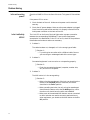
1
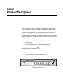
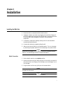
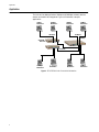
AT-FH708E Dual Speed Mini Hub Installation Guide PN 613-10758-00 Rev B Copyright 1998 Allied Telesyn International, Corp. All rights reserved. No part of this publication may be reproduced without prior written permission from Allied Telesyn International, Corp. Ethernet is a registered trademark of Xerox Corporation. All other product names, company names, logos or other designations mentioned herein are trademarks or registered trademarks of their respective owners. Allied Telesyn International, Corp. reserves the right to make changes in specifications and other information contained in this document without prior written notice. The information provided herein is subject to change without notice. In no event shall Allied Telesyn International, Corp. be liable for any incidental, special, indirect, or consequential damages whatsoever, including but not limited to lost profits, arising out of or related to this manual or the information contained herein, even if Allied Telesyn International, Corp. has been advised of, known, or should have known, the possibility of such damages. FCC Compliance Statement Note: This equipment has been tested and found to comply with the limits for a Class A digital device, pursuant to Part 15 of the FCC Rules. These limits are designed to provide reasonable protection against harmful interference when the equipment is operated in residential installation. This equipment generated, uses, and can radiate radio frequency energy and if not installed and used in accordance with the instruction manual may cause harmful interference to radio communications. However, this is no guarantee that interference will not occur in a particular installation. If this equipment does cause harmful interference to radio or television reception, which can be determined by turning the equipment off and on, the user is encouraged to try to correct the interference by one or more of the following measures: ❑ Reorient or relocate the receiving antenna. ❑ Increase the separation between the equipment and receiver. ❑ Connect the equipment into an outlet on a circuit different from that to which the receiver is connected. ❑ Consult the dealer or an experienced radio TV technician for help. Notice 1. The changes or modifications not expressly approved by the party responsible for compliance could void the user? authority to operate the equipment. 2. Shielded interface cables and AC power cord, must be used in order to comply with emission limits. CE Mark Declaration of Conformance This is to certify that this product complies with ISO/IEC Guide 22 and EN45014. It conforms to the following specifications: EMC EN55022 (1988)/CISPR 22(1985) Class A EN60555-2 (1987) Class A prEN55024-2 (1990)/IE801-2(1991) 4KV CD, 8KV AD prEN55024-3 (1991)/IE801-3(1984) 3V V/m prEN55024-4 (1992)/IE801-4(1988) 1KV - (power line) 0.5KV - (signal line) iii Table of Contents FCC Compliance Statement ....................................................................................................................................................... iii Notice ................................................................................................................................................................................... iii CE Mark Declaration of Conformance ...................................................................................................................................... iii Chapter 1 Product Description .....................................................................................................................................................................1 Package Contents ..........................................................................................................................................................................2 Front Panel ....................................................................................................................................................................................2 LEDs ...............................................................................................................................................................................................3 Rear Panel ......................................................................................................................................................................................4 DIP Switches ..................................................................................................................................................................................4 Chapter 2 Installation ....................................................................................................................................................................................5 Installing the Mini Hub ................................................................................................................................................................5 Uplink Connection ................................................................................................................................................................5 Application ....................................................................................................................................................................................6 Technical Specifications................................................................................................................................................................7 Chapter 3 Troubleshooting............................................................................................................................................................................9 Connectivity Testing .....................................................................................................................................................................9 Problem Solving ..........................................................................................................................................................................10 Is the unit receiving power?.................................................................................................................................................10 Is the Link/Activity LED lit? ................................................................................................................................................10 Appendix A Hub Specifications ......................................................................................................................................................................13 Physical Characteristics...............................................................................................................................................................13 Safety Agency ...............................................................................................................................................................................13 Cabling Specifications .................................................................................................................................................................14 Electrical Specifications...............................................................................................................................................................14 UTP (RJ45) Connector ...............................................................................................................................................................14 Network Specifications ...............................................................................................................................................................14 100Base-TX Cable .......................................................................................................................................................................15 100Base-TX Connector Pinouts .................................................................................................................................................15 Straight-through Cable........................................................................................................................................................15 Crossover Cable ...................................................................................................................................................................15 v Table of Contents Appendix B Technical Support Fax Order ....................................................................................................................................................17 Incident Summary ......................................................................................................................................................................17 Appendix C AT-FH708E Hub Installation Guide Feedback ........................................................................................................................19 Appendix D Where To Find Us ......................................................................................................................................................................21 vi Chapter 1 Product Description The AT-FH708E Mini Hub is an 8-port 10/100Mbps dual speed hub that offers a cost-effective solution to today’s growing need of network speed integration. With eight 10/100Mbps plug-and-play dual speed ports equipped in its compact body, it is possible to achieve the coexistence of 10Mbps and 100Mbps devices in a single network now and step to 100Mbps network in the future. The internal switching function provides network segmentation, thereby offering a high level of network flexibility and efficiency. Other key features include: ❑ Compliant with IEEE802.3 & 802.3u Class I and II repeater specifications ❑ 10Base-T/100Base auto-negotiate for speed detection Note All hubs operate in half-duplex only. ❑ Mini compact size with external power adapter ❑ One Uplink switch to support uplink function ❑ Two-port (port 8 and port 7) manual speed setting by DIP switches 10BASE-T / 100BASE-TX 8 PORT ETHERNET HUB POWER COLLISION 100M LINK / ACTIVITY 100M 10M 10M 1 2 3 4 5 6 7 8 UPLINK Figure 1 AT-FH708E Mini Hub 1 Package Contents Package Contents The package should include the following items: ❑ One 8-port Dual Speed Mini Hub ❑ One power adapter ❑ This Installation Guide If any item is missing, please contact your dealer immediately. Front Panel The front panel consists of the following: ❑ LEDs ❑ Uplink Switch (port 8) The LEDs help monitor the hub’s operating status and overall network performance. See Table 1 for further information concerning the LEDs. The Uplink port (port 8) has an associated uplink switch which can detect the speed of a connected device automatically and configure it properly. 100M/10M Link/Activity LEDs 10BASE-T / 100BASE-TX 8 PORT ETHERNET HUB POWER COLLISION 100M LINK / ACTIVITY 100M 10M 10M 1 POWER LED 2 3 4 5 6 7 100M/10M Collision LEDs Figure 2 AT-FH708E Mini Hub Front Panel 2 8 UPLINK Uplink Switch AT-FH708E Hub Installation Guide LEDs Table 1 lists and describes the LEDs. Table 1 LEDs LED Color Description Power Green ON indicates that the unit is receiving power Collision for 10/100M Yellow ON indicates data collisions Link/Activity for 10/100M Green Flashing Green ON indicates that a link is established FLASHING indicates that the unit is receiving data 3 Rear Panel Rear Panel The rear panel has one power connector, which accepts 5V 2.5A power input, and DIP switches for manual speed setting and eight RJ45 ports. DIP Switches for Port 7 and Port 8 Port 8 Port 7 5V 2.5A 1 2 3 4 Auto 100M 10M 8 7 6 5 4 3 2 1 Eight RJ45 Ports Auto-negotiate Switch 100M Switch 10M Switch Power Connector Figure 3 AT-FH803E Rear Panel DIP Switches Table 2 and Table 3 list the DIP switch settings for Port 8 and Port 7. To manually set the DIP switches, for example to set Port 8 for 100 Mbps (auto-negotiate OFF), push switch 1 to the UP position and Switch 2, to the DOWN position. Table 2 DIP Switch Settings for Port 8 Switch 1 Switch 2 Description UP UP Auto-negotiate ON UP DOWN 100 Mbps - Auto-negotiate OFF DOWN UP 10 Mbps - Auto-negotiate OFF Table 3 DIP Switch Settings for Port 7 Switch 3 4 Switch 4 Description UP UP Auto-negotiate ON UP DOWN 100 Mbps - Auto-negotiate OFF DOWN UP 10 Mbps - Auto-negotiate OFF Chapter 2 Installation Installing the Mini Hub 1. Place the Hub on a smooth and horizontal surface. 2. Establish network connection by plugging one end of the Category 5 UTP/STP cable RJ45 connector into the hub port, the other end to the Ethernet/Fast Ethernet adapter installed in the workstation computers. 3. If necessary, adjust port speed by setting the DIP switches before connecting network devices. 4. Connect each device by repeating Step 2 and 3. 5. Make sure that each device is connected properly. Turn on the power by attaching the power cable to the hub and plug in the power outlet. Caution Be sure to use Category 5 UTP cable in connecting 100Mbps network devices. The cable length should not exceed 100 meters. Uplink Connection 1. Set the Uplink switch to the Uplink position. 2. Attach one end of the RJ45 cable connector to the Uplink port (port 8) of the first Hub. Use Category 5 for 100 Mbps; can use Category 3, 4, or 5 of 10 Mbps. 3. Plug the other end into any RJ45 port of the second Hub. Caution Crossover cable is not necessary in establishing uplink connection through the uplink port. Caution The Uplink cable length cannot exceed 5 meters. 5 Application Application The hub can be deployed where 10Mbps and 100Mbps network devices coexist and need to be integrated. Figure 4 illustrates a sample application. 10Mbps Workstation 100Mbps Workstation 100Mbps Workstation 100Mbps Workstation 100 Meters AT-FH708E Mini Hub 100 Meters 100Mbps LINK / ACTIVITY COLLISION 10BASE-T / 100BASE-TX ETHERNET HUB DUAL SPEED FAST SWITCH WITH INTEGRATED 10BASE-T/100BASE-TX RS-232 TERMINAL PORT UTILIZATION % PORT STATUS 100M 10M LINK / ACTIVITY COLLISION Set to UPLINK 5 meters max. 100 Meters 100 Meters 100Mbps Workstation 10Mbps Workstation 100Mbps Workstation Figure 4 AT-FH708E Mini Hubs Connected to Workstations 6 100Mbps Workstation AT-FH708E Hub Installation Guide Technical Specifications Standard IEEE802.3 (10Base-T) & IEEE802.3u (100Base-TX) Class I and II Repeater 10/100BaseTX Port 8 Auto-negotiate ports Manual Speed Selectable Port (two ports are user-configurable) Port #8 and Port #7 Uplink port Port #8 Cabling Category 5 UTP/STP for 100 Mbps; Category 3, 4, or 5 UTP for 10 Mbps Operating Temperature 0~50o (32~119o) Operating Humidity 5~95% Storage Temperature 0~70o (32~158o) Storage Humidity 5~95% 7 Chapter 3 Troubleshooting This chapter describes the procedures to test and troubleshoot the hub. Connectivity Testing In the following procedure, you will test each port for a valid connection and to confirm the correct operation of the network. 1. Start with Ports 1 and 2. Connect these two ports of a single hub to two nodes or workstations and turn on the hub’s power supply. 2. Make sure the Link/Activity and other LEDs of both hub ports are lit. 3. After confirming that Port 1 and Port 2 are operational, reconnect one of the nodes/workstations to another port, then repeat this communications test with the hub’s remaining ports. Continue to verify the connection in each port by checking the Link/Activity and other activity LEDs. Note When testing the 100 Mbps ports with the MDI buttons connected to a workstation, set the button to the To PC position. If the port is auto-negotiable, wait approximately 1-3 seconds for the process to complete after power-on or after the cables are reconnected. If the port has a manual configuration switch, use the DIP switch to select the duplex mode. Reset the unit by unplugging the power and then apply power to the hub again. 4. When cascading hubs, set the MDI button to the To HUB position. 9 Problem Solving Problem Solving Is the unit receiving power? Check the POWER LED on the front of the hub. This green LED should be lit. If the power LED is not on: 1. Check the back of the unit. Make sure the power cord is attached securely. 2. Check the AC power adapter. Make sure the power adapter is plugged into a functioning wall outlet and that it is properly inserted into the hub’s power connector on the back of the unit. Is the Link/Activity LED lit? The Link LED on the front of the hub lights when a proper connection between the corresponding 10/100Base-TX port and the equipment connected to it is established. If this LED is not lit, check for the problems listed below and make corrections as necessary. 1. Problem 1: The cable has been cut, damaged, or it is the wrong type of cable. ❑ Solution 1: — Try making the connection with a different cable. Be sure you are using an undamaged cable of the correct type. 2. Problem 2: Connected equipment is not turned on or not operating properly. ❑ Solution 2: — Check the connected equipment (computer, another hub, etc.) and turn on the power. 3. Problem 3: The MDI button is in the wrong setting. ❑ Solution 3: — When using the cascade port of the hub, you should set the button to the To HUB position; otherwise, the button should be in the To PC position. — When cascading two hubs, the unit using the cascade port should have the button set to the To HUB position, while the other unit should have its switch set to To PC. — When ports with associated MDI buttons are not connected to other hubs but are used to connect to workstations or other equipment, you should set the MDI button to the To PC position. 10 AT-FH708E Hub Installation Guide 4. Problem 4: There is data loss between the hub and one of the attached network nodes. ❑ Solution 4: — Make sure that the cable length between the hub and the connected network device is no greater than 100 meters. — Make sure you are using Category 5 cable. 11 Appendix A Hub Specifications Physical Characteristics Chassis Dimensions: 6.0 in. (153 mm) (L) x 6.6 in. (169 mm) (W) x 1.8 in. (3 mm) (H) Weight: 2 lbs. 12 oz (1.25 kg.) Operating temperatures: 0° to 40° C (32o F to 104o F) Storage temperatures: -20° to 70° C (-4° F to 158° F) Relative humidity: 10% to 90% (operating) 5% to 90% (storage) Operating altitude: Up to 10,000 ft (3,048 m) Standard: IEEE 802.3 10Base-T Ethernet IEEE 802.3u, 100Base-TX Fast Ethernet EMI/RFI: Meets FCC Class A, EN55022 Class A Safety: Conforms to all standards normally supported by Allied Telesyn products, including safety standards UL 1950, CSA 22.2 No. 950, TUV and EN60950 Immunity: Conforms to EN50082-1 Immunity Standard. CE compliant Safety Agency 13 Cabling Specifications Cabling Specifications Category 5 UTP/STP for 100 Mbps; Category 3, 4, or 5 UTP for 10 Mbps Maximum of 100 meters between hub and network node Electrical Specifications Power: External power supply with 100 to 120 VAC or 200 to 240 VAC, 50/60 Hz input. UTP (RJ45) Connector Figure 5 shows an RJ45 connector. For a 100Base-TX link between switches, —any two Medium Attachment Units (MAUs)—you need a crossover cable. For a connection to a Network Interface Controller (NIC), the cable is wired straight through. Pin 1 Pin 8 Figure 5 RJ45 Connector Network Specifications Table 4 provides an overview of IEEE 802.3 and 802.3u specifications for 10Base-T and 100Base-TX network configurations using twisted-pair wiring. Table 4 IEEE 802.3 and 802.3u Network Specifications 14 10Base-T 100Base-TX Media UTP Category 3, 4 or 5 UTP/STP Category 5 only Topology Star, Tree Star, Tree External Devices Network Adapter Card, Repeater Network Adapter Card, Repeater Maximum Segment Length 100 meters (328 feet) 100 meters (328 feet) AT-FH708E Hub Installation Guide 100Base-TX Cable There are various grades of voice-quality and data-quality cables available. These can appear to be similar externally, although their highspeed data transmission characteristics are radically different. The identification problem is made worse by some suppliers selling voice-quality cables as data-quality cables. If voice-quality cables are used in a 100Base-TX network system, data movement may be slow, collision-prone or non-existent. In addition, interface LEDs will usually indicate a valid link in such cases. Category 5 is required cabling for use with 100Base-TX connections. Using any other category for a 100Base-TX connection may have high error rates and may not have the capacity to transmit data. 100Base-TX Connector Pinouts Straight-through Cable 4#7;. 5#7;0 6#5;. 7;.#4 7;0#5 5;.#6 9#5;0 5;0#9 4#7;. 5#7;0 6#5;. 7;.#4 7;0#5 5;.#6 9#5;0 5;0#9 Crossover Cable 15 Appendix B Technical Support Fax Order Name__________________________________________________________________________________ Company ______________________________________________________________________________ Address _______________________________________________________________________________ City ___________________________ State/Province____________________________________________ Zip/Postal Code _____________________ Country____________________________________________ Phone __________________________________ Fax____________________________________________ Incident Summary Model number of Allied Telesyn product I am using ___________________________________________ Network software products I am using ______________________________________________________ _______________________________________________________________________________________ Brief summary of problem ________________________________________________________________ _______________________________________________________________________________________ _______________________________________________________________________________________ Conditions (List the steps that led up to the problem.) _________________________________________ _______________________________________________________________________________________ _______________________________________________________________________________________ _______________________________________________________________________________________ Detailed description (Use separate sheet, if necessary) _______________________________________________________________________________________ _______________________________________________________________________________________ _______________________________________________________________________________________ _______________________________________________________________________________________ When completed, fax this sheet to the appropriate Allied Telesyn office. Fax numbers can be found on page 21. 17 Appendix C AT-FH708E Hub Installation Guide Feedback Please tell us what additional information you would like to see discussed in the guide. If there are topics you would like information on that were not covered in the guide, please photocopy this page, answer the questions and fax or mail this form back to Allied Telesyn International, Corp. The mailing address and fax number are at the bottom of the page. Your comments are valuable when we plan future revisions of the guide. I found the following the most valuable _______________________________________ __________________________________________________________________________________ __________________________________________________________________________________ __________________________________________________________________________________ I would like the following more developed _____________________________________ ___________________________________________________________________________ ___________________________________________________________________________ ___________________________________________________________________________ ___________________________________________________________________________ I would find the guide more useful if _________________________________________ ___________________________________________________________________________ ___________________________________________________________________________ ___________________________________________________________________________ Please fax or mail your feedback. Fax to 1-408-736-0161. Or mail to: Allied Telesyn International, Corp. c/o Technical Communications Department 950 Kifer Road Sunnyvale, CA 94086 USA 19 Appendix D Where To Find Us For Technical Support or Service Location Phone Fax Americas United States, Canada, Mexico, Central America, South America 1 (800) 428-4835 1 (918) 628-3222 Asia Singapore, Taiwan, Thailand, Malaysia, Indonesia, Korea, Philippines, China, India (+65) 3815-613 (+65) 3833-830 Australia Australia, New Zealand (+61) 2-9438-5111 (+61) 2-9438-4966 France France, Belgium, Luxembourg, The Netherlands, Middle East, Africa (+33) 1-60-92-15-32 (+33) 1-69-28-37-49 Germany Germany, Switzerland, Austria, Eastern Europe (+49) 30-435-900-126 (+49) 30-435-70-650 Hong Kong (+852) 2-529-4111 (+852) 2 529-7661 Italy Italy, Spain, Portugal, Greece, Turkey, Israel (+39) 2-416047 (+39) 2-419282 Japan (+81) 3-3443-5640 (+81) 3-3443-2443 United Kingdom United Kingdom, Denmark, Norway, Sweden, Finland, Iceland (+44) 1-235-442560 (+44) 1-235-442490 Technical Bulletin Board Service 1 (425) 483-7979 Technical Support E-mail Address [email protected] CompuServe Go ALLIED FTP Server Address: gateway.centre.com [lowercase letters] Login: anonymous [lowercase letters] Password: your e-mail address [requested by the server at login] For Sales or Corporate Information Regarding Allied Telesyn International, Corp. Allied Telesyn International, Corp. 19015 North Creek Parkway Bothell, WA 98011 Tel: 1 (425) 487-8880 Fax: 1 (425) 489-9191 Allied Telesyn International, Corp. 950 Kifer Road Sunnyvale, CA 94086 Tel: 1 (800) 424-4284 (USA and Canada) Fax: 1 (408) 736-0100 World Wide Web: http://www.alliedtelesyn.com 21