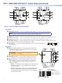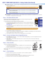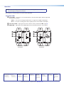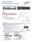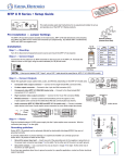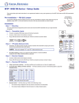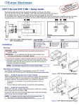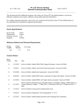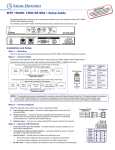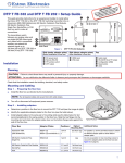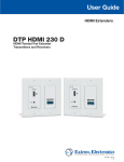
1
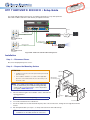
NT: plete
RTAfor the coomns, and
O
P
m
IM n.co
tructi
the
s
o
.extr
on in nnecting
www stallati
e.
co
Go to uide, in s before er sourc
g
n
ow
user cificatio
the p
to
e
t
p
s
uc
prod
DTP T HWP/UWP D 232/332 D • Setup Guide
This setup guide provides instructions for an experienced installer to set up and operate the
Extron DTP T HWP D and DTP T UWP D family of wallplate extenders.
INPUTS
OUTPUTS
INPUTS
1 2 3 4 5 6 7 8
MENU
SIGNAL
1
CONFIG
2
3
4
5
6
7
8
A
B
C
HDCP
VOLUME
ENTER
Extron
IN1608
SCALING PRESENTATION SWITCHER
IN1608 SA
AMPLIFIED OUTPUT
2x25W(8Ω)/2x50W(4Ω)
INPUTS
AUDIO INPUTS
OUTPUTS
L
OUTPUTS
R
OVER DTP
RS-232
1
5
3
7
2
LINK
HDMI
HDMI
4
OVER DTP
RS-232
6
L
IR
Tx Rx G Tx Rx
SIG
CONFIGURABLE
100-240V ~ -- A MAX
C
8
SIG
LINK
IR
OVER DTP
RS-232
1
R
L
3
R
L
5
R
1
2
CLASS 2 WIRING
REMOTE
A
SIG
+48V
LINK
HDMI
IR
B
L
2
R
L
4
R
L
6
R
MIC/LINE
2
LAN
VARIABLE
L
R
RESET
RS-232
+48V
DTP IN
Tx Rx G Tx Rx
DTP IN
Tx Rx G Tx Rx
Tx Rx G
DTP OUT
Ethernet
50/60 Hz
IN1608
AUTO SW
AUDIO IN
HDCP
1
AUDIO IN
VGA IN
HDMI IN
XTP DTP 24 Cable
CONFIG
IR OUT
G
IPCP 505
230 '
S
COM
RTS
SWITCHED
12VDC
R
1
2
LIMIT
3
4
OVER
CTS
TX
IR/S
RELAY
FLEX
I/O
2
3
4
1
2
3
4
1
2
ACT LIMIT
5
6
7
8
5
6
7
8
3
4
OVER
2
3
4
5
6
7
8
LINK
Network
IR
ACT
RX
1
100
eBUS
1
TX
RX
TLP 1000TV
IPCP 505
Extron
DTP T UWP 232 D Tx
Transmitter
XTP DTP 24 Cable
AUDIO IN
HDMI IN
HDCP
1
SIG
AUDIO IN
HDMI IN
2
XTP DTP 24 Cable
CONFIG
IR OUT
G
LINK
OUTPUTS
POWER
12V
0.7A MAX
230 '
AUTO SW
L
AUDIO
R
DTP IN
DTP HDMI 230 Rx
HDMI
230 '
S
Projector
Extron
DTP T HWP 232 D Tx
Transmitter
A Typical DTP T HWP 232 D and DTP T UWP 232 D Application
Installation
Step 1 — Disconnect Power
Disconnect all equipment power sources.
Step 2 — Prepare the Mounting Surface
ATTENTION:
• Installation and service must be performed by authorized
personnel only.
• The installation shall be in accordance with applicable
provisions of the National Electrical Code and any local
electrical codes.
Wall Stud
Screws or
Nails
Wall opening is
flush with edge of box.
NOTE: Use a wall box with a depth of at least 3.0 inches
(7.6 cm). Alternatively, the included mud ring (MR 200)
can be used. For more information, see the full product
user guide at www.extron.com.
Cable
Clamp
TO
MI
HD
a.
Place the wall box against the installation surface and mark the
opening guidelines.
TIP: Use a level to mark the opening.
DIO
IN
AU
A IN
VG
IN
IN
NF
IG
CO
T
IR
OU
G
S
Signal Output
Cable
b. Cut out the material from the marked area.
c.
SW
AU
CP
HD
1
DIO
AU
Extron
DTP T UWP 232/332 D
Decora Faceplate
Secure the wall box to the wall stud with 10-penny nails or #8 or #10 screws, leaving the front edge flush with the
surface.
d. Run all required cables (see steps 3, 4, and 5) and secure them with cable clamps.
TIP: In order to fit the unit in the junction box, do not
install boots on TP cables and RJ-45 connectors.
DTP T HWP/UWP 232/332 D • Setup Guide (Continued)
AUTO SW
AUTO SW
AUDIO IN
A
HDMI IN
HDCP
1
2
AUDIO IN
A
A
B
B
AUDIO IN
A
C
CONFIG
CONFIG
IR OUT
IR OUT
D
AUDIO IN
VGA IN
HDMI IN
HDMI IN
B
HDCP
1
S
G
E
D
Extron
DTP T HWP 232/332 D
Front Panel
E
S
G
Extron
DTP T UWP 232/332 D
Front Panel
Step 3 — Connect Inputs to the Transmitter
Front Panel
A
Audio input connector — Connect an unbalanced stereo audio source to this 3.5 mm mini stereo jack.
NOTE: The units do NOT embed analog audio onto the HDMI signal. This analog audio signal is
transmitted simultaneously with audio embedded within the HDMI signal.
B
C
D
HDMI input connector — Connect an HDMI cable between this port and the output port of the digital video source.
E
Mini USB port — Connect a male Mini USB B cable to this port for SIS configuration and
firmware updates.
VGA input connector — Connect a VGA cable between this port and the output port of the video source.
IR output connector — Connect an IR device to this 2-pole, 3.5 mm captive screw pass-through connector for IR
control. Wire the cable as shown in the illustration to the right.
S
G
Signal
Ground
3/16”
(5 mm) Max.
Rear Panel
A
DC power input connector — Wire and plug the included external
12 VDC power supply into either this 2-pole connector or the power
input connector on the receiver.
2
D
DTP T HWP/UWP 232/332 D
Rear Panel
Connected RS-232 and
Contact Closure Device Pins
1
2
Tx/Rx
Pins
Tx Rx G
Contact — Momentarily short pins 1 or 2 to ground (G) to select
the corresponding input. Connect pins 1 and 2 to ground (G) to
set the unit to auto switch mode. The device selects the highest
active input (auto switch).
Contact
•
RS-232
RS-232 — To control the unit through this port, connect an RS-232
device and configure it as follows: 9600 baud rate, 8 data bits,
1 stop bit, no parity.
C
DTP OUT
SIG
LINK
•
A/S
Remote connector — Connect an RS-232 device, contact closure
device, or both to this 5-pole, 3.5 mm captive screw connector to
control switching on the unit. Wire the connector as shown in the
diagram to the right.
A
B
REMOTE
RS-232 CONTACT
Tx Rx
G 1 2
C
OVER
DTP
Over DTP connector — Connect an RS-232 device to this 3-pole,
3.5 mm captive screw connector for pass-through RS-232 control.
E
POWER
12V
0.9 A MAX
B
R
Tx Rx G
connecting the power supply.
+–
ATTENTION: See Step 6 on the following page before wiring or
Pin 2 for contact closure control
Pin 1 for contact closure control
Ground
Transmit pin on connected unit
Receive pin on connected unit
6
DTP T HWP/UWP 232/332 D • Setup Guide (Continued)
D
DTP OUT connector — Connect one end of a twisted pair cable to this RJ-45 connector and the opposite
end to a compatible receiver.
SIG
LINK
SIG
LINK
ATTENTION: Do not connect this device to a telecommunications or computer data network.
DTP OUT
NOTES:
• The DTP T HWP/UWP 232 D models can transmit video, control, and audio (if applicable)
signals up to 230 feet (70m).
• The DTP T HWP/UWP 332 D models can transmit video, control, and audio (if applicable)
signals up to 330 feet (100m).
E
Reset button — Use an Extron Tweeker or small screwdriver to press and hold the recessed button for 6 seconds while
the switcher is running to perform a factory reset.
Step 4 — Run Cables Between Units
Pins:
12345678
Connect the rear panel transmitter output to a rear panel receiver input using twisted pair cable.
Wire the cable as shown in the diagram to the right.
1 White-orange
2
For optimal performance, Extron highly recommends the following:
zz
zz
TIA/EIA
T568B
Pin Wire color
RJ-45 termination with shielded twisted pair cable must comply with TIA/EIA-T568B wiring
standard for all connections.
For more information on TP cable wiring and termination, see the full product user guides at
www.extron.com.
Use shielded twisted pair cable, 24 AWG solid conductor or better, with a minimum cable
bandwidth of 400 MHz.
White-green
4
Blue
5
White-blue
Green
6
TP Wires
Orange
3
7
White-brown
8
Brown
ATTENTION: Do not use Extron UTP23SF-4 Enhanced Skew-Free AV UTP cable or STP201 cable.
zz
Use shielded RJ-45 plugs to terminate the cable.
zz
Limit the use of RJ-45 patches. Overall transmission distance capabilities vary depending on the number of patches
used. If possible, limit the number of patches to 2 total.
zz
If RJ-45 patches must be used in the system, shielded patches are recommended.
Step 5 — Connect the Outputs from a Compatible Receiver
a.
DVI or HDMI output connector — Connect a DVI or HDMI cable (depending on your receiver type) between this port
and the input port of the display.
b. Audio output — Connect a stereo audio device to this 3.5 mm mini stereo jack to receive the passed-through
unbalanced audio.
c.
RS-232/IR Pass-Through connector — Plug an RS-232 or modulated IR device into the RS-232/IR pass-through port.
Step 6 — Power the Units
The units can be powered one of two ways:
zz
Locally with the included power supply. A compatible receiver can then be powered
remotely through the DTP line.
zz
Remotely via the DTP line by a locally powered DTP 230 or 330 compatible device.
Wire the 2-pole captive screw connector for the included external 12 VDC power supply as
shown at right.
Step 7 — Final Installation
a.
3/16"
(5 mm) Max.
Smooth
A
SECTION A–A
Power Supply
Output Cord
Make all connections, power the units, and test the system for satisfactory operation.
b. At the power outlet, unplug the power supply.
c.
Mount the transmitter into the wall box, and attach the supplied Decora faceplate to the unit.
d. At the power outlet, reconnect the power supply. This powers up both units.
3
Ridges
A
Captive Screw
Connector
DTP IN
Operation
NOTE: Input switching can only be performed via auto switching, RS-232, or contact
closure through the rear panel connectors.
After all devices are powered up, the system is fully operational.
Transmitter LEDs
A
Power LEDs — These two-color front panel LEDs on the transmitters light to indicate signal and
power status as follows:
Amber — The unit is receiving power but there is no signal on the HDMI or VGA inputs.
Green — The unit is receiving power and a signal is present on the HDMI or VGA inputs.
B
C
Auto Switch LED — Lights green when auto switch is active (see Rear Panel C on page 2).
HDCP LED — Lights green when HDMI input has been authenticated on the source device.
A
A
B
C
AUTO SW
AUDIO IN
B
C
HDCP
1
HDMI IN
2
AUDIO IN
HDMI IN
AUTO SW
AUDIO IN
HDCP
1
VGA IN
HDMI IN
CONFIG
CONFIG
IR OUT
IR OUT
S
S
G
G
Extron
Extron
DTP T HWP 232/332 D
Front Panel
Extron Headquarters
+800.633.9876 Inside USA/Canada Only
Extron USA - West
Extron USA - East
+1.714.491.1500+1.919.850.1000
+1.714.491.1517 FAX
+1.919.850.1001 FAX
AUDIO IN
Extron Europe
+800.3987.6673
Inside Europe Only
Extron Asia
+800.7339.8766
Inside Asia Only
+31.33.453.4040
+31.33.453.4050 FAX
+65.6383.4400
+65.6383.4664 FAX
DTP T UWP 232/332 D
Front Panel
Extron Japan
+81.3.3511.7655
+81.3.3511.7656 FAX
Extron China
+4000.EXTRON
+4000.398766
Inside China Only
Extron
Middle East
+971.4.2991800
+971.4.2991880 FAX
+86.21.3760.1568
+86.21.3760.1566
FAX
© 2014 Extron Electronics All rights reserved. www.extron.com
Extron Korea
+82.2.3444.1571
+82.2.3444.1575 FAX
Extron India
1.800.3070.3777
Inside India Only
+91.80.3055.3777
+91.80.3055 3737
FAX
68-2547-50 Rev. B
03 14