1
WELLS MANUFACTURING COMPANY
2 ERIK CIRCLE, P. O. Box 280
Verdi, NV 89439
Customer Service (775) 345-0444 Ext.502
fax: (775) 345-0569
www.wellsbloomfield.com
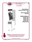
363
SERVICE
MANUAL
for
ELECTRIC
FRYER
MODELS
AE-55F
WF
WFAE-55F
and
WF
AE-55FS
WFAE-55FS
IMPORTANT: WELLS MANUFACTURING PROPRIETARY INFORMATION.
DISSEMINATION OF THIS INFORMATION TO ANYONE OTHER THAN
WELLS AUTHORIZED SERVICE AGENTS IS STRICTLY PROHIBITED.
TECHNICAL CONTENT OF THIS MANUAL IS DESIGNED FOR
USE BY QUALIFIED PROFESSIONAL TECHNICIANS ONLY.
Part. No 503043 Rev. (-)
S362 041000 cps
SAFETY PROCEDURES
Knowledge of proper procedures is essential to the safe operation of electrically energized
equipment. In accordance with generally accepted product safety labeling guidelines for
potential hazards, the following signal words and symbols are used throughout this manual.
DANGER
DANGER - Danger is used to indicate the presence of a hazard which will
cause severe personal injury, death, or substantial property damage in the
event the statement is ignored.
WARNING - Warning is used to indicate the presence of a hazard which can cause
personal injury and possibly death, or major property damage, in the event the statement is ignored.
CAUTION - Caution is used to indicate the presence of a hazard which will or can
cause minor personal injury, or property damage in the event the statement is ignored.
CAUTION - Used to indicate the presence of an electrical hazard which will or can
cause personal injury, or property damage in the event the statement is ignored.
NOTE - Note is used to notify personnel of installation, operation or maintenance information
which is important, but not hazard related.
FRYER PRECAUTIONS AND GENERAL INFORMATION
1.
This fryer is intended for use to deep fry food products for human consumption. No other use
is recommended or authorized by the manufacturer or its agents.
2.
Service technicians must be familiar with the appliance use, limitations and associated hazards.
Operating instructions and warnings must be read and understood by all operators and users.
3.
Your WELLS fryer is equipped with an oil filtration system, which is designed to filter hot
shortening ONLY. Water, cleaning agents or other liquids will damage the FILTER PUMP.
4.
This piece of equipment is made in the USA and, except where otherwise noted, has American sizes
on hardware.
5.
This manual supplements the Owners Manual (p/n 300007) for this equipment. Refer to the
Owners Manual for normal operating procedures and programming procedures.
6.
Any troubleshooting guides, electrical diagrams, component views or parts lists included in this
manual are intended for use by qualified service technicians only.
7.
Service instructions for the Solid Shortening Melt Option will be covered in a future supplement.
xi
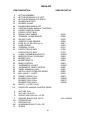
TABLE OF CONTENTS
Safety Procedures
Inside Cover
Specifications
1
Features and Operating Controls
WFAE-55F
2
WFAE-55FS
4
Operation
Heating and Cooking Instructions
6
Troubleshooting Operational Problems
8
Filtering Instructions
10
Troubleshooting Filtering Problems
11
Servicing Instructions
Cradle Lift Assembly
12
Kettle and Electrical Components
14
Filter Pump Assembly
20
Parts Breakdown (FOR GENERAL REFERENCE ONLY)
22
Wiring Diagrams
24
Service Parts List
26
GENERAL SPECIFICATIONS
DIMENSIONS
Wide
Deep
High (Basket Raised)
15.70”
37.38”
48.94”
CAPACITIES
Cooking Oil (Liquid Shortening Only)
Chicken (fresh) (Standard Basket)
Chicken (frozen) (Standard Basket)
Lb.
55
30
25
Kg.
25
13
11
ELECTRICAL
Voltage Requirement
208 VAC
240 VAC
(380-415 VAC Europe)
NOTE: 3Ø OPERATION ONLY - THIS FRYER IS NOT APPROVED FOR
CONVERSION TO 1Ø
Power Consumption
17,000 Watts
Amperage
208V 3∅
240V 3∅
380-415V 3∅
47.8 Amp per leg
43.0 Amp per leg
27.0 Amp per leg
1
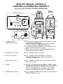
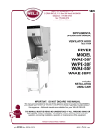
WFAE-55F (MANUAL CONTROLS)
FEATURES and OPERATING CONTROLS
(see page 4 for SOLID STATE CONTROLLER WFAE-55FS)
FRONT VIEW
BACK VIEW
UPPER CONTROL PANEL
15
16
1
17
3
FRYER
22
OFF
FILTER
HEAT
POWER
14
COOK
12
LOWER CONTROL PANEL
325
300
ON
HI-LIMIT
RESET
8
18
THERMOSTAT
FILTER
OFF
CAUTION
FRYER MUST BE OFF
BEFORE USING FILTER
350
11
275
375
23
250
ºF
9
13
10
1. POWER SWITCH
(FRYER-OFF-FILTER)
FRYER position turns ON the FRYER and POWER LIGHT and
turns OFF the FILTER PUMP.
Heating elements are energized and regulate to the temp.
set on the CONTROL THERMOSTAT (item 10).
OFF position turns OFF the FRYER and de-energizes the lower
panel FILTER PUMP SWITCH (item 8).
FILTER position energizes the lower FILTER PUMP SWITCH
(item 8) and turns OFF the FRYER.
2. POWER LIGHT (amber)
When lit: indicates FRYER is energized.
3. HEAT LIGHT (amber)
When lit: indicates HEATING ELEMENT is energized.
Light turns OFF when oil has reached temp preset on
CONTROL THERMOSTAT
4. COOK LIGHT (amber)
When lit: indicates the TIMER (item 5) is ON and the BASKET
(item 15) is lowered.
5. TIMER
Controls the LIFT CRADLE and the BUZZER. TIMER is started
by pressing the red button in the center of the knob. When the
red button is pressed the LIFT CRADLE lowers. The red
pointer on the dial shows time remaining. When TIMER
reaches “0”, BUZZER sounds and LIFT CRADLE raises.
6. BUZZER LIGHT (amber)
When lit: indicates BUZZER SWITCH (item 7) is turned ON and
BUZZER CIRCUIT is active.
2
7.
BUZZER SWITCH
Activates the BUZZER CIRCUIT. When turned ON and TIMER
has reached “0”, BUZZER will sound until BUZZER SWITCH
is turned OFF or TIMER is activated.
8.
FILTER PUMP SWITCH
(ON - OFF)
Causes the oil to be filtered and pumped back into the FRYPOT.
The POWER SWITCH (item 1) must be in the FILTER
position for the FILTER PUMP SWITCH to operate.
CAUTION: FIRE HAZARD / HOT OIL
THE HI-LIMIT THERMOSTAT IS A FIRE PROTECTION DEVICE.
If tripping persists, clean the space between the
hi-limit bulb and the element to enhance oil flow and to facilitate reset.
Otherwise, contact your authorized Wells service agency for repairs.
DO NOT ATTEMPT TO BYPASS OR HOLD IN THE BUTTON OF THE
HI-LIMIT THERMOSTAT. A FIRE WILL RESULT.
9.
HI-LIMIT THERMOSTAT
Provides over-temperature protection by de-energizing HEATING
ELEMENTS if the oil temperature exceeds the factory-set limit.
RESET must be performed manually. Allow the oil to cool
below 300ºF (149ºC), then firmly press the red button on the
LOWER CONTROL PANEL.
10.
TEMPERATURE CONTROL
THERMOSTAT
Controls the oil temperature from 250ºF (121ºC) turned fully
counter-clockwise, to 375ºF (191ºC) fully clockwise.
11.
DRAIN VALVE LEVER
Opens and closes the DRAIN VALVE.
To OPEN, rotate the handle until it points down.
To CLOSE, rotate the handle to the horizontal position.
12.
POWER OUTLET BOX
Contains the electrical service connection terminal block.
13.
OIL FILTER RESERVOIR
Holds the filter screen.
14.
FILTER PUMP MOTOR
RESET BUTTON
(located at the rear
of the motor)
The FILTER PUMP MOTOR is equipped with an over-heating
protection device.
RESET must be performed manually. Allow the motor to
cool for approx. 15 min., then press the red button.
15.
LIFT CRADLE
Raises and lowers FRY BASKET.
16.
FRY BASKET
Sits on the LIFT CRADLE and holds product to be cooked.
Raised and lowered by the LIFT CRADLE.
17.
LIFT MOTOR
Raises / lowers LIFT CRADLE. Accessible for lubrication thru
the access plate in back panel.
18.
DRIP PAN
Gathers fluids that accumulate on the top of the fryer section of
Ventilator Hood models (i.e. WVAE-55F).
22.
ELECTRICAL DIAGRAM
Installation and troubleshooting (for qualified technicians).
23.
DATA PLATE
Identifies the appliance manufacturer, model and serial number;
also gives electrical rating.
3
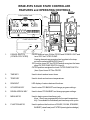
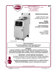
WFAE-55FS SOLID STATE CONTROLLER
FEATURES and OPERATING CONTROLS
FRONT VIEW
BACK VIEW
UPPER CONTROL PANEL
15
16
3
1
17
FRYER
TIME
OFF
TEMP
HEAT
READY
MANUAL
FILTER
22
1
2
3
4
5
6
MANUAL
7
PAUSE
CLEAN
STANDBY
BASKET
FILTER
14
8
12
LOWER CONTROL PANEL
18
HI-LIMIT
RESET
23
9
10
11
13
1.
POWER SWITCH
(FRYER-OFF-FILTER)
FRYER position turns ON the FRYER and POWER LIGHT and
turns OFF the FILTER PUMP.
Heating elements are energized and regulate to the temp.
set on the selected MENU KEY(item 7).
OFF position turns OFF the FRYER and de-energizes the lower
panel FILTER PUMP SWITCH (item 8).
FILTER position energizes the lower FILTER PUMP SWITCH
(item 8) and turns OFF the FRYER.
2.
TIME KEY
Used to check and set menu times.
3.
TEMP KEY
Used to check and set menu temperatures.
4.
READOUT
LED display of various data and functions.
5.
UP ARROW KEY
Used to raise FRY BASKET and change program settings .
6.
DOWN ARROW KEY
Used to lower FRY BASKET and change program settings .
7.
MENU KEYS
Used to begin a menu time/temp cycle.
Keys 1 thru 6 are programmable for time and temperature;
Key 7 is available for individually set time/temp cook cycles
8.
FUNCTION KEYS
Used to perform the functions of PAUSE, CLEAN, STANDBY,
BASKET (raise/lower) and FILTER (warning/acknowledge)
4
CAUTION: FIRE HAZARD / HOT OIL
THE HI-LIMIT THERMOSTAT IS A FIRE PROTECTION DEVICE.
If tripping persists, clean the space between the
hi-limit bulb and the element to enhance oil flow and to facilitate reset.
Otherwise, contact your authorized Wells service agency for repairs.
DO NOT ATTEMPT TO BYPASS OR HOLD IN THE BUTTON OF THE
HI-LIMIT THERMOSTAT. A FIRE WILL RESULT.
9.
HI-LIMIT THERMOSTAT
Provides over-temperature protection by de-energizing the
HEATING ELEMENTS if the oil temperature exceeds
the factory-set limit.
RESET must be performed manually. Allow the oil to cool
below 300ºF (149ºC), then press the red button on the
LOWER CONTROL PANEL.
10.
SONALERT
Audible alarm to signal end of a cook cycle and other
programmed functions.
11.
DRAIN VALVE LEVER
Opens and closes the DRAIN VALVE.
To OPEN, rotate the handle until it points down.
To CLOSE, rotate the handle to the horizontal position.
12.
POWER OUTLET BOX
Contains the electrical service connection terminal block.
13.
OIL FILTER RESERVOIR
Holds the filter screen.
14.
FILTER PUMP MOTOR
RESET BUTTON
(located at the rear
of the motor)
The FILTER PUMP MOTOR is equipped with an overheating protection device.
RESET must be performed manually. Allow the motor to
cool for approx. 15 min., then press the red button.
15.
LIFT CRADLE
Raises and lowers FRY BASKET.
16.
FRY BASKET
Sits on the LIFT CRADLE and holds product to be cooked.
Raised and lowered by the LIFT CRADLE.
17.
LIFT MOTOR
Raises / lowers LIFT CRADLE. Accessible for lubrication thru
access plate in back panel.
18.
DRIP PAN
Gathers fluids that accumulate on the top of the fryer section of
Ventilator Hood models (i.e. WVAE-55FS).
22.
ELECTRICAL DIAGRAM
Installation and troubleshooting (for qualified technicians).
23.
DATA PLATE
Identifies the appliance manufacturer, model and serial number;
also gives electrical rating.
5
OPERATION
HEATING INSTRUCTIONS
IMPORTANT: Never press the POWER SWITCH to FRYER unless the heating
elements are covered with shortening. Except for fryers equipped with the Solid Shortening
Option, use LIQUID SHORTENING only. Check shortening level marker inside
the cooking basket for proper shortening level.
NOTE: Except for fryers equipped with the Solid Shortening Option, the fryer is designed
to be used with LIQUID SHORTENING only. Lard and solid shortening will solidify in the
filter pump, causing pump failure.
1. WFAE-55F and WVAE-55F:
a. Set the TEMPERATURE CONTROL THERMOSTAT to 350º F.
b. Press POWER SWITCH to FRYER position. The contactor will close and the
HEATING ELEMENTS will start heating the shortening. The HEAT LIGHT will turn ON
any time the TEMPERATURE CONTROL THERMOSTAT is calling for heat and the
HEATING ELEMENTS are energized. NOTE: The first time the HEAT LIGHT goes out,
the fryer is ready to begin cooking.
2. WFAE-55FS and WVAE-55FS:
a. Program MENU KEY times and temperatures (see IOM Manual, p/n 300007).
b. Press POWER SWITCH to FRYER position. The controller will energize the HEATING
ELEMENTS until the shortening has reached the programmed temperature. The readout
will display “PRE” and “HEAT” and the selected MENU KEY, and the HEAT indicator will be
lit until the shortening has reached temperature. When the readout displays “00:00”, the
fryer is ready to begin cooking.
6
COOKING INSTRUCTIONS
1.
LOAD PRODUCT
a.
Load frozen product into the BASKET. Using the plastic-coated handles, set the
BASKET on the LIFT CRADLE.
b.
For fresh meat product, lower the basket and hand drop the product just above the oil
level to prevent splattering.
IMPORTANT: Different products contain different amounts of moisture, which will
cause the hot oil to foam. Determining the maximum safe load size that will prevent
hazardous overflow and splatter of hot oil. This can be accomplished by starting
with a small load, and gradually increasing the load size until the maximum load
which can be cooked without the oil foaming over the top of the frypot is reached.
2. WFAE-55F and WVAE-55F:
a. Set the TIMER for the time required to cook the particular product weight. Press the red
button in the center of the TIMER. The CRADLE LIFT will lower and the TIMER will start
counting-down. The COOK LIGHT will turn ON when the cradle is fully lowered.
Turn the BUZZER SWITCH to ON.
b. At the completion of the timed cycle, the TIMER will reach 0, the BUZZER will sound and
the CRADLE LIFT will raise.
The BASKET and the cooked product will be hot.
Contact with hot cooked product can cause serious injury.
3. WFAE-55FSand WVAE-55FS:
a. Press the “BASKET” KEY followed by the “DOWN ARROW” KEY. When the cradle if fully
lowered, press the desired MENU KEY.
b. At the completion of the timed cycle, the cradle will rise and the sonalert will sound.
The BASKET and the cooked product will be hot.
Contact with hot cooked product can cause serious injury.
4. Use the plastic-coated handles to remove the BASKET and dump the cooked product into a
suitable tray or container.
7
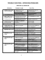
TROUBLE SHOOTING - OPERATING PROBLEMS
WFAE-55F and WVAE-55F
PROBLEM
POWER LIGHT not lit
(Fryer not operating)
(Fryer operating norm.)
HEAT LIGHT not lit
(POWER LIGHT lit)
(Cooking oil cold)
POWER LIGHT not lit
(Cooking oil cold)
(Cooking oil hot)
POSSIBLE CAUSE
SOLUTION
POWER SWITCH not
in FRYER position
Circuit breaker OFF or tripped
Service wiring problem
POWER LIGHT defective
Press POWER SWITCH
to FRYER position
Reset circuit breaker
Correct service wiring
Replace LIGHT
TEMPERATURE CONTROL
THERMOSTAT set too low
TEMPERATURE CONTROL
THERMOSTAT defective
HI-LIMIT THERMOSTAT
TRIPPED
HEAT LIGHT defective
Set THERMOSTAT to 350ºF
Replace THERMOSTAT
Allow oil to cool
Reset HI-LIMIT
Replace LIGHT
COOK LIGHT not lit
(CRADLE LIFT raised)
(CRADLE LIFT lowered)
TIMER not energized
COOK LIGHT defective
Set and energize TIMER only
when ready to cook
Replace LIGHT
BUZZER LIGHT not lit
BUZZER SWITCH in OFF pos.
BUZZER LIGHT defective
Turn SWITCH ON
Replace LIGHT
BUZZER does not
sound
BUZZER SWITCH in OFF pos.
BUZZER defective
BUZZER SWITCH defective
Turn SWITCH ON
Replace BUZZER
Replace SWITCH
CRADLE LIFT won’t
lower
TIMER not energized
TIMER defective
LIFT MOTOR defective
MICROSWITCH misadjusted
Set and energize TIMER only
when ready to cook
Replace TIMER
Replace LIFT MOTOR
Adjust MICROSWITCH
TIMER has time remaining
LIFT CRADLE not properly
assembled to LIFT ROD
TIMER defective
LIFT MOTOR defective
MICROSWITCH misadjusted
ACTUATOR or LIFT CRADLE
damaged
Allow TIMER to drop to 0
Install white plastic pivot over
end of lift rod (see page 3)
Replace TIMER
Replace LIFT MOTOR
Adjust MICROSWITCH
Repair / replace damaged
components
CRADLE LIFT won’t
raise
8
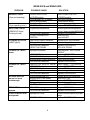
WFAE-55FS and WVAE-55FS
PROBLEM
READOUT not lit
(Fryer not operating)
POSSIBLE CAUSE
SOLUTION
POWER SWITCH not
in FRYER position
Circuit breaker OFF or tripped
Service wiring problem
Controller connection faulty
CONTROLLER defective
Press POWER SWITCH
to FRYER position
Reset circuit breaker
Correct service wiring
Check/replace connector
Replace CONTROLLER
HEAT LIGHT not lit
(READOUT lit and
Cooking oil cold)
Programmed temperature
CONTROLLER defective
HI-LIMIT THERMOSTAT
TRIPPED
Raise programmed temperature
too low / select another MENU KEY
Replace CONTROLLER
Allow oil to cool
Reset HI-LIMIT
COOKING OIL COLD
(HEAT light lit)
HEATING ELEMENT defective
Wiring problem / loose connection
CONTROLLER defective
DEFECTIVE PROBE
Replace HEATING ELEMENT
Correct wiring problem
Replace CONTROLLER
REPLACE PROBE
CRADLE LIFT won’t
lower
Improper key strokes
LIFT MOTOR defective
DOWN RELAY defective
Wiring problem / loose connection
CONTROLLER defective
Press”BASKET” then “DOWN
ARROW”
Replace LIFT MOTOR
Replace RELAY
Correct wiring problem
Replace CONTROLLER
CRADLE LIFT won’t
raise
READOUT not “00:00” or “PAUSE”
LIFT MOTOR defective
DOWN RELAY defective
Wiring problem / loose connection
CONTROLLER defective
Press “PAUSE” + “UP ARROW”
Replace LIFT MOTOR
Replace RELAY
Correct wiring problem
Replace CONTROLLER
BUZZER does not
sound, or is not
loud enough
Buzzer programmed OFF
BUZZER SHUTTER closed
BUZZER defective
Wiring problem / loose connection
CONTROLLER defective
Contact factory for instructions
Open SHUTTER
Replace BUZZER
Correct wiring problem
Replace CONTROLLER
MENU KEY does not
operate
MENU KEY not programmed
CONTROLLER defective
Program MENU KEY
Replace CONTROLLER
FUNCTION KEY does
not operate
Improper KEY entry
Consult owners manual for proper
usage
Replace CONTROLLER
(Fryer operating norm.)
CONTROLLER defective
9
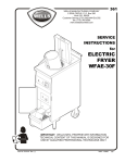
OIL FILTERING INSTRUCTIONS
DANGER
1.
OIL MUST BE FILTERED WHILE HOT (300ºF AND HIGHER)
Contact with hot oil can cause serious injury including death.
Always wear protective clothing and insulated gloves when
filtering the cooking oil.
Refer to the Installation, Operation and Maintenance Manual (p/n 300007) for complete operating
instructions for the filter system. Make certain the FILTER LEAF is properly assembled and
installed.
TOP VIEW
STRAIGHT PIN
SIDE VIEW
FILTER RAIL “A”
UPPER
FILTER SCREEN
SEPARATOR
LOWER
FILTER SCREEN
FILTER RAIL “B”
“L”-SHAPED PIN
2.
The cooking oil must be hot (minimum of 300º F.) in order to filter properly. Cold oil will not flow
through the filter leaf. Place the POWER SWITCH to the FILTER position. DO NOT turn the
pump ON for more than 10 sec. without oil flowing.
3.
Open the DRAIN LEVER. The WOOD DOWEL may be needed to unplug the drain hole.
4.
While draining the oil, press the POWER SWITCH to FILTER. Pour the FILTER POWDER into
the oil at the point where it is being drawn down the drain.
5.
After all the oil has drained from the FRYPOT, use the HI-TEMP BRUSH to push breading crumbs
and other debris down the drain.
NOTE: use caution not to damage the two small CAPILLARY TUBES toward the front of the
HEATING ELEMENT.
6.
After 5 minutes of oil circulation, close the DRAIN VALVE and allow the FRYPOT to fill with
the freshly filtered oil. When all the oil has returned to the FRYPOT, turn OFF the FILTER
SWITCH. Turn the POWER SWITCH to the OFF position until starting to use the fryer again.
7.
Allow the FILTER RESERVOIR to cool before servicing. Refer to the IOM Manual
(p/n 300007) for complete FILTER RESERVOIR maintenance instructions.
NOTE: Refrain from using soap in the FRYPOT or FILTER RESERVOIR. Soap residue
will cause the cooking oil to breakdown rapidly.
10
TROUBLE SHOOTING - OIL FILTERING PROBLEMS
PROBLEM
FILTER PUMP won’t
run
POSSIBLE CAUSE
POWER SWITCH not in
FILTER position
PUMP MOTOR OVERLOAD
tripped
Defective POWER SWITCH
PUMP will not pump
cooking oil
SUCTION TUBE not seated in
SUCTION RECEPTACLE
SUCTION TUBE O-RING
missing or damaged
Damaged SUCTION TUBE
or SUCTION RECEPTACLE
FILTER LEAF clogged
PUMP CHECK VALVE plugged
or reversed
PUMP pumps lots of
bubbles in cooking oil
SUCTION TUBE not seated in
SUCTION RECEPTACLE
SUCTION TUBE O-RING
missing or damaged
Insufficient oil entering or in
FILTER RESERVOIR
SOLUTION
Press POWER SWITCH to
FILTER position
Allow motor to cool, then
press red RESET button on
back of PUMP MOTOR
Replace SWITCH
Make sure FILTER RESERVOIR is properly installed
Replace O-RING with one of
the three spares in groove
Replace damaged
components
Scrape crumbs and other
debris from FILTER LEAF
Service FILTER RESERVOIR
at next opportunity
Clean CHECK VALVE
Install CHECK VALVE properly
Make sure FILTER RESERVOIR is properly installed
Replace O-RING
Incrementally open DRAIN
VALVE and/or clear crumbs
and other debris from DRAIN
PUMP MOTOR tripped
won’t reset
PUMP jammed with debris
Defective PUMP HEAD
Defective PUMP MOTOR
Unjam PUMP
Replace PUMP HEAD
Replace MOTOR only
Oil is not being filtered
completely
FILTER LEAF O-RING missing,
damaged or LEAF mis-installed
FILTER LEAF surface clogged
witth debris
Properly install FILTER LEAF
11
AFTER OIL COOLS, remove
FILTER LEAF, disassemble
and clean
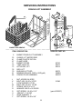
SERVICING INSTRUCTIONS
CRADLE LIFT ASSEMBLY
82
71
S
6
79
V
K
U
R
76
73
81
72
L
J
Y
BASKET AND CRADLE
M
67
41
33
P
LIFT
ITEM DESCRIPTION
SERVICE PART NO.
6
33
41
67
71
72
73
76
79
81
82
BASKET CRADLE LIFT ASSEMBLY
GUARD, LIFT MOTOR ROD
CLAMP, PLASTIC 3/8” DIA.
CLAMP, HOSE
BASKET, FRYER
YOKE, ROD LIFT
ACTUATOR, LIFT
ROD, LIFT
BUSHING, LIFT ROD
BEARING, ROLLER .75OD x .25ID (pk6)
CRADLE PIVOT ASSEMBLY
J
K
L
M
P
R
S
U
V
Y
NUT, ACORN 1/4-20 SS
BOLT, HEX 1/4-20 x 34” SS
LOCK WASHER 1/4” SS
BOLT, HEX 1/4-20 x 1/2” SS
SCREW, HEX 3-32 x 1/2”
WASHER .265 ID x .50 OD SS
SET SCREW, 1/4-20 x 5/16”
JAM NUT, 1”-14 UNF
WAVE WASHER, 1”
SET SCREW, 1/4-20 x 5/8”
69961
69743
69812
69814
69972
500031
500037
61048
(part of 500037)
12
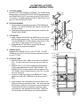
LIFT MOTOR / LIFT ROD
ASSEMBLY INSTRUCTIONS
A. LIFT ROD GUARD
Assemble LIFT ROD GUARD into FRAME. The GUARD slides
through holes in the MOTOR MOUNT PLATE and the bottom of
the FRAME BACK PLATE, and rests on the BOTTOM PLATE
of the frame. It is held in place by HOSE CLAMPS above and
below the MOTOR MOUNT PLATE.
B. LIFT ROD BUSHING
1. The top bushing assembles through the TOP PANEL and
FRAME. The WAVE WASHER and JAM NUT go BELOW
top part of frame.
2. The bottom bushing assembles through the top hole in the
FRAME BACK PANEL.
C. LIFT MOTOR
1. Apply voltage to the BLACK and WHITE wires of the motor
until the screw stops turning. This is the full-down position.
Turn the BRASS NUT until the distance from the top of the
nut to the top of the screw is 10-1/4” to 10-3/8”.
2. Assemble the LIFT MOTOR to the MOTOR MOUNT
PLATE with four bolts and threadlock.
D. CRADLE PIVOT
Assemble the CRADLE PIVOT to the LIFT ROD. The SET
SCREW on the PIVOT COLLAR must be centered on the flat
on the LIFT ROD.
E. LIFT ROD YOKE
1. Slide the fingers of the YOKE over the flats of the BRASS
NUT. The set screws must be on the side away from the
motor.
2. Slide the PIVOT / LIFT ROD through the top BUSHING,
YOKE, bottom BUSHING and LIFT ROD GUARD. The
CRADLE PIVOT must be parallel to the rear portion of the
TOP PANEL, with the downturned lip of the PIVOT toward
the front of the fryer.
3. Center the YOKE on the flats of the BRASS NUT, then
tighten the YOKE SET SCREWS on the flat on the LIFT
ROD.
4. Apply voltage to the motor leads and carefully observe the
end points of the up-and-down motion. The yoke must clear
the bushings: adjust by loosening the yoke set screws and
“bumping” the lift motor as required by applying voltage
momentarialy to the appropriate motor leads. Tighten the
set screws and re-test for proper up-and-down operation.
13
D
B
E
B
C
A
TOP PANEL
LIFT ROD
LIFT ROD
BUSHING
FRAME
LIFT
MOTOR
YOKE
LIFT ROD
BUSHING
FRAME
BACK PLATE
CLAMP
MOTOR
MOUNT
PLATE
LIFT ROD
GUARD
FRAME
BOTTOM
PLATE
KETTLE AND ELECTRICAL COMPONENTS
WFAE-55F (also WVAE-55F)
Q
52
23
50
80
78
22
53
4
54
69
25
39
114
15
43
A
66
24
LL
F
HH
X
16
51
JJ
61
48
A
47
KK
74
42
88
45
63
26
35
46
55
14
WFAE-55F
ITEM DESCRIPTION
4
15
16
22
23
24
25
26
35
39
42
43
45
46
47
48
50
51
52
53
54
55
61
63
66
69
74
78
80
88
114
A
F
Q
X
HH
JJ
KK
LL
SERVICE PART NO.
KETTLE ASSEMBLY
KETTLE RETAINING CLIP, LEFT
KETTLE RETAINING CLIP, RIGHT
ELEMENT SUPPORT
ELEMENT CLAMP
ELEMENT BACKING PLATE
CONTROL PANEL, MANUAL CONTROLS
LOWER CONTROL PANEL
COVER, OUTLET BOX
SIGNAL LIGHT, AMBER
TERMINAL, FLAME SENSOR
ON-OFF PLATE
JUMPER, FLAME SENSOR
FUSE, SC-10 10A 300V (pk 4)
FUSE HOLDER
TERMINAL, 3P 85A
CONTACTOR, 3P 240V
CONTACTOR, 3P 208V
CLAMP, THERMO BULB SAFETY
MERCURY RELAY, 3P 208/240V
BUZZER, 240V
BUZZER SWITCH
KNOB, CONTROL
THERMOSTAT, HI-LIMIT
THERMOSTAT, TEMP. CONTROL
TIMER, 40MIN 60Hz 240V
SWITCH, DPDT FILTER/OFF/FRYER
BALL VALVE, 1-1/4 NPT
GASKET, GORTEX (kit)
ELEMENT, 220V 8.5Kw
ELEMENT, 240V 8.5Kw
ELEMENT, 208V 8.5Kw
NIPPLE, 1-1/4 NPT x 5.88”
FACEPLATE, MANUAL CONTROL PANEL
NUT, KEP, 8-32
NUT, HEX 1/4-20 SS
SCREW, PAN PHL 8-32 x 1/2 SS
WASHER, BELLEVILLE .261 ID
STRAIN RELIEF
GROUND LUG
ALUMINUM HEX NUT, 8-32 x 7/8”
SCREW
50516
53068
53192
54005
54871
54769
50131
57780
57779
502332
63920
64834
64904
65653
502469
66688
68469
69550
69816
66863
500448
500013
500009
(incl. in 66863)
15
KETTLE AND ELECTRICAL COMPONENTS
WFAE-55FS (also WVAE-55FS)
Q
70
23
37
52
80
37
50
78
38
22
4
69
66
25
15
114
A
24
16
HH
F
51
JJ
61
48
X
A
LL
63
74
KK
42
88
45
86
37
26
55
35
16
75
WFAE-55FS
ITEM DESCRIPTION
4
15
16
22
23
24
25
26
35
37
38
42
45
48
50
51
52
55
61
63
66
69
70
74
75
78
80
86
88
114
A
F
Q
X
HH
JJ
KK
LL
SERVICE PART NO.
KETTLE ASSEMBLY
KETTLE RETAINING CLIP, LEFT
KETTLE RETAINING CLIP, RIGHT
ELEMENT SUPPORT
ELEMENT CLAMP
ELEMENT BACKING PLATE
CONTROL PANEL, SOLID STATE
LOWER CONTROL PANEL
COVER, OUTLET BOX
SPARK QUENCHER
RELAY, SOLID STATE
TERMINAL, FLAME SENSOR
JUMPER, FLAME SENSOR
TERMINAL BLOCK, 3P 85A
CONTACTOR, 3P 240V
CONTACTOR, 3P 208V
CLAMP, THERMO BULB SAFETY
MERCURY RELAY, 3P 208/240V
SONALERT
THERMOSTAT, HI-LIMIT
TEMPERATURE PROBE
SOLID STATE CONTROL MODULE
SWITCH, DPDT FILTER/OFF/FRYER
TRANSFORMER, 208/240V TO 24V
BALL VALVE, 1-1/4 NPT
TERMINAL STRIP
GASKET, GORTEX (kit)
ELEMENT, 220V 8.5Kw
ELEMENT, 240V 8.5Kw
ELEMENT, 208V 8.5Kw
RETAING CLIP, TEMP. PROBE WIRING
NIPPLE, 1-1/4 NPT x 5.88”
FACEPLATE, SOLID STATE CONTROL
NUT, KEP, 8-32
NUT, HEX 1/4-20 SS
SCREW, PAN PHL 8-32 x 1/2 SS
WASHER, BELLEVILLE .261 ID
STRAIN RELIEF
GROUND LUG
ALUMINUM HEX NUT 8-32 x 7/8”
SCREW
500688
501455
503068
54005
500131
57780
57779
502322
63920
500974
502469
501465
500830
69550
501454
69816
8552-18
66863
500448
500013
500009
(incl. in 66863)
17
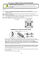
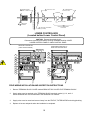
1/4" ("Gortex") GASKET INSTALLATION PROCEDURE
CAUTION: Exposed electrical circuits.
Disconnect electrical power before attempting to replace heating elements or
thermostats.
The drawings below show top view of the Gortex Gasket and Belleville Washer installation and nut tightening
sequence.
STEP 1. Install the 1/4" Gortex gasket (p/n 66864) over the element studs. DO NOT USE RTV!
Insert the element through the frypot, element and gasket on the inside of the frypot, and studs through
the appropriate holes.
STEP 2. Install four 1/4" Belleville washers with the high center away from the frypot, as shown (4 places).
STEP 3. Install four nuts finger tight.
STEP 4. Using a torque wrench, tighten all four nuts 1/2 turn at a time. Working in a cross pattern, tightening each
nut in sequence until a uniform reading of 70 inch-pounds is achieved on all four nuts.
STEP 5. Wait 2 minutes and re-torque all four nuts to 70 inch-pounds.
STEP 6. Wait an additional two minutes and re-torque all four nuts to a uniform 70 inch-pounds.
FRYPOT ELEMENT
NUT TIGHTENING SEQUENCE
TOP VIEW
1
4
3
GASKET BEHIND
2
VIEW FROM FRONT OF UNIT
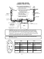
THERMOBULB / CAPILLARY INSTALLATION
HI-LIMIT BULB: LEFT SIDE
TEMPERATURE CONTROL BULB: RIGHT SIDE (WFAE-55F)
3/8“
max.
BULB
3/8“
max.
SAFETY CLAMP
HOLDS BULB
CLEAR OF
ELEMENT
TWO CLAMPS
HOLD BULB
ONE CLAMP HOLDS
CAPILLARY
PLACE CLAMPS WITHIN 3/8“
OF THE ENDS (WIDE PORTION)
OF BULB
1.
Insert the feed-thru bushing through the green gasket, and insert both through the frypot wall. Slidethe
Belleville washer over the protruding threads of the bushing, with the high center of the washer away from the
frypot. Thread the locknut onto the bushing and tighten. Torque the lock nut to 30 inch pounds.
Please Note: The 17mm. hex head feed thru bushing pictured at the left of the drawing MUST NOT be
rotated during the assembly procedure. Always support the bushing with a box wrench while tightening the
assembly to avoid damage to the green gasket!
2.
Slip the bulb of the capillary tube through the bushing. Mount the bulb to the center portion of the element
with safety clamps, positioning the clamps within 3/8” of the ends of the widest part of the bulb. Route the
capillary tube alongside of the element, but out of the way of cleaning brushes, etc. Secure the capillary
tube near the frypot end of the element with a safety clamp.
3.
Seat the washers and oil seal into the bushing. Insert the compresson nut into the bushing, and torque to
30 - 40 inch pounds.
NOTE: Use care to not twist or kink the capillary
.
18
1
OUTSIDE OF FRYPOT
4
FEED-THRU
BUSHING
LOCK NUT, 17mm
5
COMPRESSION
NUT, 10mm
WASHER
INSIDE OF FRYPOT
2 GREEN GASKET
NOTE: FRAGILE
CAPILLARY
3
BELLEVILLE WASHER
(p/n 69962)
BLACK OIL SEAL
PART OF THERMOSTAT
CAPILLARY
LOWER CONTROL BOX
(Located behind Lower Control Panel)
CAUTION: Exposed electrical circuits
Disconnect electrical power before opening TERMINAL BLOCK COVER
LOWER CONTROL PANEL or MAIN CONTROL PANEL.
WFAE-55F and WVAE-55F
(-55FS FRYERS SIMILAR)
COMPONENTS SPECIFIC TO
WFAE-55FS and WVAE-55FS
66
54
53
38
50
37
52
70
60
LL
24
39
66
69
69
48
HH
37
JJ
42
98
47
61
63
61
55
75
45
99
FIELD WIRING INSTALLATION AND INSPECTION INSTRUCTIONS
1.
Remove TERMINAL BLOCK COVER marked REMOVE THIS COVER FOR TERMINAL BLOCK.
2.
Supply wires must be attached to the TERMINAL BLOCK terminals marked L1, L2, and L3.
Green GROUND wire must be attached to the GROUND LUG marked “
”.
3.
Supply wires must be routed and secured away from the FRYPOT, FILTER MOTOR and tubing/plumbing.
4.
Replace all covers and panels when the installation is completed.
19
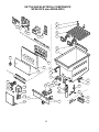
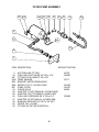
FILTER PUMP ASSEMBLY
44F 44W
56M
56P
96
95
92
64
89
97
32
56B
90
68
3
ITEM DESCRIPTION
3
32
44F
44W
56B
56M
56P
64
68
89
90
97
96
92
95
SERVICE PART NO.
SUCTION LINE FITTING
FLEX LINE, SUCTION SS 3/4” OD x 16.5”
FITTING, FLEX CONDUIT 3/8” x 90º
FIBER WASHER
BRACKET, MOTOR STABILIZING
MOTOR, FILT 1P 125/230V 50/60
PUMP, FILTER
CHECK VALVE
ADAPTER 1/2” NPT FEMALE x 15/16M FLARE
ADAPTER, 3/8” FPT FEMALE x 3/4M FLARE
FLEX LINE, PRESSURE SS .6” OD x 13.5”
ADAPTER 1/2” NPT MALE x 15/16M FLARE
BUSHING, REDUCER 1/2” NPT x 3/8” NPT
NIPPLE, 3/8” x CLOSE
FITTING, 3/8” NPT 90º STREET ELL
20
66720
502287
50177
501205
501231
66692
502283
89
FILTER PUMP / MOTOR
ASSEMBLY INSTRUCTIONS
APPLY PIPE SEALANT (RECOMMEND LOCTITE™
PST HI-TEMP) TO MALE PIPE THREADS.
DO NOT APPLY ANY TYPE OF PIPE COMPOUND
OR TAPE AT FLARE FITTINGS.
FR
YP
OT
☺
☺
ADAPTER
1/2“FPT x
3/4“ M FLARE
ASSEMBLE FLARE FITTINGS FINGER TIGHT
WITHOUT ANY TYPE OF PIPE COMPOUND.
THEN, TORQUE FLARE FITTING:
DISCHARGE TUBE TO 25 ft-lb
SUCTION TUBE TO 33 ft-lb.
ALWAYS USE A BACKUP WRENCH ON THE
MALE FLARE FITTING.
DO NOT ALLOW CORRUGATED PIPE TO
TWIST DURING ASSEMBLY.
SUCTION
FITTING
☺
ADAPTER
1/2“ FPT x
15/16“ M FLARE
DO NOT BEND CORRUGATED TUBE
WITHIN 1“ OF ANY FITTING .
TOP
☺
FLEX HOSE
.6“ OD x 9.5”
FLEX HOSE
.75“ x 16.5”
☺
ADAPTER
3/8“FPT x 3/4” M FLARE
CHECK VALVE
ARROW POINTS
TOWARD FRYPOT
“TOP” GOES UP
ADAPTER
1/2“MPT x 15/16” M FLARE
PUMP /
MOTOR
NIPPLE 3/8“ x CLOSE
BUSHING 3/8“ x 1/2”
CAUTION: New style motor is a dual voltage rated unit, and must be field
wired to match the electrical service supply voltage. Motor may be shipped
wired for either 230V or 125V. Verify the supply voltage and the motor voltage
configuration. If necessary, rewire motor, at the terminal block in the end of the
motor, per the table shown below. Also, see diagram on motor.
WARNING: Failure to correctly wire the motor will result in permanent damage to the pump motor.
M
O
T
O
R
T
E
R
M
I
N
A
L
S
125V
2
1
3
5
1 (LINE)
2
4
3
4
5
6
6 (LINE)
YELLOW / BLACK
BLUE
BLUE
(UNUSED)
BLACK
BROWN
ORANGE
WHITE
YELLOW
21
230V
1(LINE)
2
3
4
5
6 (LINE)
YELLOW / BLACK
BLUE
BLUE
BROWN
BLACK
WHITE
ORANGE
YELLOW
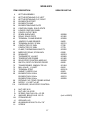
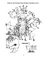
WFAE-55F PARTS BREAKDOWN (GENERAL REFERENCE ONLY)
ITEM
DESCRIPTION
ITEM
DESCRIPTION
1
2
3
4
5
6
8
15
16
17
18
19
20
21
22
23
24
25
26
27
29
32
33
34
35
36
39
40
41
42
43
44
45
46
47
48
50
51
52
53
54
55
56
57
58
59
60
DOOR ASSY
RESERVOIR ASSY
SUCTION LINE FITTING ASSY
KETTLE ASSY
FRAME ASSY
CRADLE LIFT ASSY
KETTLE COVER ASSY
KETTLE RETAINING CLIP, LEFT
KETTLE RETAINING CLIP, RIGHT
HINGE BRACKET, DOOR, TOP
HINGE BRACKET, DOOR, BOTTOM
SIDE PANEL, RIGHT
SIDE PANEL, LEFT
CLIP, CONTROL BOX
SUPPORT, ELEMENT
CLAMP, ELEMENT
BACKING PLATE, ELEMENT
CONTROL PANEL W/BUZZER
PANEL, HI-LIMIT/THERMOSTAT
TOP PANEL
FILTER LEAF
HOSE ASSY, ¾”x13.5” LG SS
GUARD, LIFT MOTOR ROD
OUTLET BOX
COVER, OUTLET BOX
COVER, SUCTION LINE BRACKET
SIGNAL LIGHT, AMBER
GROMMET, INSULATION 7/8”
CABLE CLAMP, PLASTIC 3/8” DIA.
TERMINAL, FLAME SENSOR
PANEL, ON/OFF SWITCH
FITTING, CONDUIT, 90º x 3/8”
JUMPER, FLAME SENSOR
FUSE, SC-10, 10A 300V
FUSE HOLDER, HPG-EE 10A
TERMINAL BLOCK, 3P 85A
CONTACTOR, 3P
SAFETY CLAMP, THERMOBULB
MERCURY RELAY, 3P
BUZZER, 240V
SWITCH, TOGGLE W/SEAL
KNOB, CONTROL
FILTER MOTOR, 1P 230V
O-RING, .50ID x .63OD
LEG, ADJUSTABLE
MAGNET, DOOR
KIT, CAPILLARY FEEDTHRU
61
62
63
64
65
66
67
68
69
71
72
73
74
76
78
79
80
81
82
83
88
89
90
92
95
96
97
THERMOSTAT, HI-LIMIT
LUG, GROUND
THERMOSTAT, TEMP CONTROL
CHECK VALVE
CASTER, RIGID, 5”
TIMER, 40 MIN 60Hz 240V
CLAMP, HOSE
ADAPTER, ½”FTP x 15/16M FLARE
SWITCH, ROCKER, POWER
FRYER BASKET
YOKE, ROD, LIFT MOTOR
LINEAR ACTUATOR, 1/10HP 240V
BALL VALVE, 1-1/4” NPT
ROD, LIFT MOTOR
GASKET, ELEMENT, GORTEX
BUSHING, LIFT ROD
ELEMENT, 8.5Kw
BEARING, ROLLER, .75OD x .25ID
CRADLE PIVOT ASSY
PROTECTIVE COVER, 5”x7”
NIPPLE, 1-1/4” NPT x 5.88” BI
ADAPTER, 3/8”FPT x ¾”M FLARE
HOSE ASSY, .6” OD x 13.5” LG SS
NIPPLE, 3/8” NPT x CLOSE
FITING, 3/8” NPT STREET ELL 90º
REDUCER, 1/2x3/8 NPT
ADAPTER, ½”MPT x 15/16” M FLARE
A
F
H
J
K
M
P
Q
R
S
U
V
W
X
Y
NUT, KEP 8-32 Zi
NUT, HEX ¼-20 SS
NUT, TENZ 8-32, GREEN
NUT, ACORN, ¼-20 SS
BOLT, HEX, ¼-20 x 3/4” SS
BOLT, HEX, ¼-20 x ½” SS
SCREW, HEX, 8-32 x ½”
SCREW, PAN PHL, 8-32 x ½” SS
WASHER, .265 ID x .50 ID SS
SET SCREW ¼-20 x 5/16”
NUT, JAM, 1”-14 NF
WAVE WASHER, 1”
BELLEVILLE WASHER, .504 ID
BELLEVILLE WASHER, .261 ID
SET SCREW, SQUARE HEAD, 1/4-20 X 5/8”
22
WFAE-55F PARTS BREAKDOWN (GENERAL REFERENCE ONLY)
23
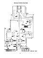
WFAE-55F WIRING DIAGRAM
24
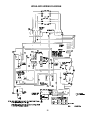
WFAE-55FS WIRING DIAGRAM
25
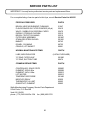
SERVICE PARTS LIST
IMPORTANT: Use only factory authorized service parts and replacement filters.
For a complete listing of service parts for this fryer, consult Service Parts List AS025.
FRYER ACCESSORIES
PART#
BRUSH, HEATING ELEMENT CLEANING
FLAVOR SAVER OIL FILTER POWDER (45 pk)
WAOC-1 MOBILE OIL DISPOSAL CADDY
PADDLE, STIRRING CHICKEN
BRUSH, FRYPOT CLEANING
FILTER LEAF ASSEMBLY
STAINLESS STEEL SHOVEL
BASKET
DOWEL, CLEANING
CRADLE, LIFT BASKET
21647
22410
22470
22515
22516
501847
501901
69743
69752
69961
NORMAL MAINTENANCE ITEMS
PART #
LUBE, MOLYDISULFIDE
“O” RING, FILTER LEAF
“O” RING, SUCTION TUBE
(LOCAL PURCHASE)
501900
66474
COMMON REPAIR ITEMS
PART #
CONTROLLER, SOLID STATE
ELEMENT, 208V 8.5Kw
ELEMENT, 240V, 8.5Kw
LIFT MOTOR
TEMPERATURE PROBE
MERCURY RELAY
THERMOSTAT, HI-LIMIT
GASKET KIT, ELEMENT
500830
500009
500013
500513
501465
63920
66663
66863
Wells Manufacturing Company, Service Parts Department
2 Erik Circle, P. O. Box 280
Verdi, NV 89439
phone: (775) 345-0444 Ext. 504 fax: (888) 492-2783
26
NOTES
27
IMPORTANT: WELLS MANUFACTURING PROPRIETARY INFORMATION.
DISSEMINATION OF THIS INFORMATION TO ANYONE OTHER THAN
WELLS AUTHORIZED SERVICE AGENTS IS STRICTLY PROHIBITED.
TECHNICAL CONTENT OF THIS MANUAL IS DESIGNED FOR
USE BY QUALIFIED PROFESSIONAL TECHNICIANS ONLY.
WELLS MANUFACTURING COMPANY
2 ERIK CIRCLE, P. O. Box 280
Verdi, NV 89439
Service Parts Dept. (888) 492-2782
fax: (888) 492-2783
[email protected]