1
MICROWAVE OVEN
CE1150R
CE1150R(SILVER)
Manual
MICROWAVE OVEN
CONTENTS
1. Precaution
2. Specifications
3. Operating Instructions
4. Disassembly and Reassembly
5. Alignment and Adjustments
6. Troubleshooting
7. Exploded Views and Parts List
8. PCB Diagrams
9. Schematic Diagrams
SRSC
ELECTRONICS
This Service Manual is a property of Samsung Electronics Co.,Ltd.
Any unauthorized use of Manual can be punished under applicable
International and/or domestic law.
©Samsung Electronics Co., Ltd. December 2003
Printed in Korea
Code No. : DE68-03317A
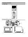
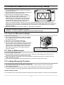
3. Operating Instructions
3-1 Control Panel
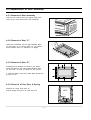
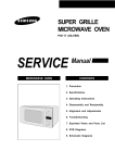
3-2 Features & External Views
Door
Ventilation Holes
Light
Safety Interlock Holes
Control Panel
Guide Roller
Glass Plate
Coupler
Grill Rack
312mm
Door Latches
234mm
355mm
522mm
539mm
ڈٻڏٻڈ
3. Operating Instructions
3-1 Control Panel
3-2 Features & External Views
Door
Ventilation Holes
Light
Safety Interlock Holes
Control Panel
Guide Roller
Glass Plate
Coupler
Grill Rack
312mm
Door Latches
234mm
355mm
522mm
539mm
ڈٻڏٻڈ
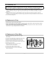
4. Disassembly and Reassembly
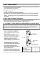
4-1 Replacement of Magnetron, Motor Assembly and Lamp
Remove the magnetron including the shield case,
permanent magnet, choke coils and capacitors (all
of which are contained in one assembly).
1. Disconnect all lead wires from the magnetron
and lamp.
2. Remove the bracket mounting.
3. Remove the magnetron supporter.
4. Remove the air cover.
5. Remove screws securing the magnetron to the
wave guide.
6. Take out the magnetron very carefully.
7. Remove screws from the back panel.
8. Take out the fan motor.
9. Remove the oven lamp by rotating to pull out from
hole of air cover.
NOTE1: When removing the magnetron, make sure that its antenna does not hit any adjacent parts, or it
may be damaged.
NOTE2: When replacing the magnetron, be sure to remount the magnetron gasket inthe correct position and
make sure the gasket is in good condition.
4-2 Replacement of High Voltage Transformer
1.
2.
3.
4.
Discharge the high voltage capacitor.
Disconnect all the leads.
Remove the mounting bolts.
Reconnect the leads correctly and firmly.
PRECAUTION
Servicemen should remove their watches
whenever
working close to or replacing the magnetron.
PRECAUTION
There exists HIGH VOLTAGE ELECTRICITY with
high current capabilities in the circuits of the
HIGH VOLTAGE TRANSFORMER secondary
and filament terminals. It is extremely dangerous
to work on or near these circuits with the oven
energized.
DO NOT measure the voltage in the high voltage
circuit including filament voltage of magnetron.
ڈٻڐٻڈ
4-3 Replacement of Door Assembly
4-3-1 Removal of Door Assembly
Remove hex bolts securing the upper hinge and
lower hinge. Then remove the door assembly.
4-3-2 Removal of Door "C"
Insert flat screwdriver into the gap between Door
"E" and Door "C" to remove Door "C". Be careful
when handling Door "C" because it is fragile.
4-3-3 Removal of Door "E"
Door "E"
Following the procedure as shown in the figure,
insert and bend a thin metal plate between Door
"E" and Door "A" until you hear the 'tick' sound.
1. Insertion depth of the thin metal plate should be
0.5mm or lesU
4-3-4 Removal of Key Door & Spring
Remove pin hinge from Door "E"
Detach spring from Door "E" and key door.
ڈٻڑٻڈ
4-3-5 Reassembly Test
After replacement of defective component parts of the door, reassemble it and follow the instructions
below for proper installation and adjustment so as to prevent an excessive microwave leakage.
1. When mounting the door to the oven, be sure to adjust the door parallel to the bottom line of the
oven face plate by moving the upper hinge and lower hinge in the direction necessary for proper
alignment.
2. Adjust so that the door has no play between the inner door surface and oven front surface. If the door
assembly is not mounted properly, microwave energy may leak from the space between the door and oven.
3. Do microwave leakage test.
4-4 Replacement of Fuse
1. Disconnect the oven from the power source.
2. When 15A fuse blows out by the operation of interlock monitor switch failure, replace the primary interlock
switch, door sensing switch, monitor switch and power relay.
3. When the above three switches operate properly, check if any other part such as the control circuit board,
blower motor or high voltage transformer is defective.
4-5 Replacement of Drive Motor
1. Take out the glass tray, guide roller and coupler
from cavity.
2. Turn the oven upside down to replace the drive motor.
3. Remove a screw securing the drive motor cover.
4. Disconnect all the lead wires from the drive motor.
5. Remove screws securing the drive motor to the cavity.
6. Remove the drive motor.
7. When replacing the drive motor, be sure to
remount it in the correct position.
8. Connect all the leads to the drive motor.
9. Screw the drive motor cover to the base plate
with a screw driver.
ڈٻڒٻڈ
4-6 Replacement of Control Circuit Board
4-6-1 Removal of Control Box Assembly
1. Be sure to ground any static electric charge in
your body and never touch the control circuit.
2. Disconnect the connectors from the control
circuit board.
3. Remove screws securing the control box
assembly.
4. Remove the screw securing the ground tail of
the keyboard.
Control Box
Screw
4-6-2 Removal of Ass'y P.C.B Assembly
1. Remove screws securing the control circuit
board.
2. Lift up the control circuit board from the Ass'y
control box.
ASSY PCB
SCREWS
ڈٻړٻڈ
5. Alignment and Adjustments
PRECAUTION
1. High voltage is present at the high voltage terminals during any cook cycle.
2. It is neither necessary nor advisable to attempt measurement of the high voltage.
3. Before touching any oven components or wiring, always unplug the oven from its power source and
discharge the high voltage capacitor.
5-1 High Voltage Transformer
1. Remove connectors from the transformer terminals
and check continuity.
2. Normal resistance readings are as follows:
Secondary
Approx. 137˟
Filament
Approx. 0˟
Primary
Approx. 1.594˟
(Room temperature = 20° C)
5-2 Low Voltage Transformer
1. The low voltage transformer is located on the
Assy base plate.
2. Remove the low voltage transformer from the
Assy base plate and check continuity.
3. Normal resistor reading is shown in the table.
Terminals
5-3 Magnetron
1. Continuity checks can indicate only an open
filament or a shorted magnetron. To diagnose an
open filament or shorted magnetron :
2. Isolate the magnetron from the circuit by
disconnecting its leads.
3. A continuity check across the magnetron filament
terminals should indicate one ohm or less.
4. A continuity check between each filament terminal
and magnetron case should read open.
ڈٻڔٻڈ
Resistance
1~2(Input)
290Ω.
3~4(Output)
4.0Ω..
5~6(Output)
1.0Ω.
5-4 High Voltage Capacitor
1.
2.
3.
4.
5.
Check continuity of the capacitor with the meter set at the highest resistance scale.
Once the capacitor is charged, a normal capacitor shows continuity for a short time, and then indicates 9Mഐ.
A shorted capacitor will show continuous continuity.
An open capacitor will show constant 9Mഐ.
Resistance between each terminal and chassis should read infinite.
5-5 High Voltage Diode
1. Isolate the diode from the circuit by disconnecting its leads.
2. With the ohm-meter set at the highest resistance scale, measure across the diode terminals. Reverse the
meter leads and read the resistance. A meter with 6V, 9V or higher voltage batteries should be used to
check the front-to back resistance of the diode (otherwise an infinite resistance may be read in both
directions). The resistance of a normal diode will be infinite in one direction and several hundred Kഐin the
other direction.
5-6 Main Relay and Power Control Relay
1. The relays are located on the PCB Ass'y. Isolate them from the main circuit by disconnecting the leads.
2. Operate the microwave oven with a water load in the oven. Set the power level set to high.
3. Check continuity between terminals of the relays after the start pad is pressed.
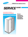
5-7 Adjustment of Primary Switch, Door Sensing Switch and Monitor Switch
Precaution
For continued protection against radiation hazard, replace parts in accordance with the wiring diagram and be sure to
use the correct part number for the following switches: Primary and secondary interlock switches, and the interlock
monitor switch (replace all together). Then follow the adjustment procedures below. After repair and adjustment, be
sure to check the continuity of all interlock switches and the interlock monitor switch.
1. When mounting Primary switch and Interlock
Monitor switch to Latch Body, consult the figure.
2. No specific adjustment during installation of
Primary switch and Monitor switch to the latch
body is necessary.
3. When mounting the Latch Body to the oven
assembly, adjust the Latch Body by moving it so
that the oven door will not have any play in it.
Check for play in the door by pulling the door
assembly. Make sure that the latch keys move
smoothly after adjustment is completed.
Completely tighten the screws holding the Latch
Body to the oven assembly.
4. Reconnect to Monitor switch and check the
continuity of the monitor circuit and all latch
switches again by following the components test
procedures.
Secondary
Interlock Switch
Body Latch
Lever Switch(A)
Lever Switch(B)
Door Sensing Switch
(Primary Interlock)
5. Confirm that the gap between the switch
housing and the switch actuator is no more than
0.5mm when door is closed.
6. Interlock Switch Replacement - When
replacing faulty switches, be sure switch mounting
tabs are not bent, broken or otherwise deficient in
their ability to secure the switches in place.
Interlock Monitor
Switch
Door Open Door Closed
Primary switch
∞
0
Monitor switch(COM-NC)
0
∞
Door Sensing S/W
∞
0
ڈٻڋڌٻڈ
5-8 Output Power of Magnetron
CAUTION
MICROWAVE RADIATION
PERSONNEL SHOULD NOT ALLOW EXPOSURE TO MICROWAVE RADIATION FROM MICROWAVE
GENERATOR OR OTHER PARTS CONDUCTING MICROWAVE ENERGY.
The output power of the magnetron can be measured by performing a water temperature rise test.
Equipment needed :
* Two 1-liter cylindrical borosilicate glass vessel (Outside diameter 190 mm)
* One glass thermometer with mercury column
NOTE: Check line voltage under load. Low voltage will lower the magnetron output. Make all temperature
and time tests with accurate equipment.
1. Fill the one liter glass vessel with water.
2. Stir water in glass vessel with thermometer, and record glass vessel's temperature ("T1", 10±1° C).
3. After moving the water into another glass vessel, place it in the center of the cooking tray. Set the oven to
high power and operate for 49 seconds exactly. (3 seconds included as a holding time of magnetron
oscillation:)
4. When heating is finished, stir the water again with the thermometer and measure the temperature ("T2").
5. Subtract T1 from T2. This will give you the water temperature rise. (ଠT)
6. The output power is obtained by the following formula;
Output Power =
4.187 x 1000 x ଠT + 0.88 x Mc x(T2-T0)
46
49 : Heating Time (sec)
4.187 : Coefficient for Water
1000 : Water (cc)
ଠT : Temperature Rise (T1-T2)
Mc : Cylindrical borosilicate glass weight
To : Room Temperature
7. Normal temperature rise for this model is 9°C to 11°C at 'HIGH'.
NOTE 1: Variations or errors in the test procedure will cause a variance in the temperature rise.
Additional power test should be made if temperature rise is marginal.
NOTE 2: Output power in watts is computed by multiplying the temperature rise (step E) by a factor of 91
times the of centigrade temperature.
ڈٻڌڌٻڈ
5-9 Procedure for Measurement of Microwave Energy Leakage
1) Pour 275±15cc of 20±5° C(68±9° F) water in a beaker
which is graduated to 600cc, and place the beaker in
the center of the oven.
2) Start to operate the oven and measure the leakage by
using a microwave energy survey meter.
3) Set survey meter with dual ranges to 2,450MHz.
4) When measuring the leakage, always use the 2 inch
spacer cone with the probe. Hold the probe
perpendicular to the cabinet door. Place the spacer
cone of the probe on the door and/or cabinet door
seam and move along the seam, the door viewing
window and the exhaust openings moving the
probe in a clockwise direction at a rate of 1 inch/sec. If the leakage testing of the cabinet door seam is
taken near a corner of the door, keep the probe perpendicular to the areas making sure that the probe end
at the base of the cone does not get closer than 5cm to any metal. If it gets closer than 5cm, erroneous
readings may result.
5) Measured leakage must be less than 4mW/cm2 , after repair or adjustment.
Maximum allowable leakage is 5mW/cm2 .
4mW/cm2 is used to allow for measurement and meter accuracy
5-10 Check for Microwave Leakage
1. Remove the outer panel.
2. Pour 275±15cc of 20±5°C(68±9°F) water in a beaker
which is graduated to 600cc, and place the beaker in
the center of the oven.
3. Start the oven at the highest power level.
4. Set survey meter dual ranges to 2,450MHz.
5. Using the survey meter and spacer cone as described
above, measure near the opening of magnetron, the
surface of the air guide and the surface of the wave
guide as shown in the following photo.( but avoid the
high voltage components.) The reading should be
less than 4mW/cm2 .
WARNING
AVOID THE HIGH VOLTAGE COMPONENTS
5-11 Note on Measurement
1) Do not exceed the limited scale.
2) The test probe must be held on the grip of the handle, otherwise a false reading may result when the
operator's hand is between the handle and the probe.
3) When high leakage is suspected, do not move the probe horizontally along the oven surface; this may
cause damage to the probe.
4) Follow the recommendation of the manufacturer of the microwave energy survey meter.
5-12 Leakage Measuring Procedure
5-12-1 Record keeping and notification after measurement
1) After adjustment and repair of a radiation preventing device, make a repair record for the measured
values, and keep the data.
2) If the radiation leakage is more than 4 mW/cm2 after determining that all parts are in good condition,
functioning properly and the identical parts are replaced as listed in this manual notify that fact to ;
CENTRAL SERVICE CENTER
5-12-2 At least once a year have the microwave energy survey meter checked for accuracy by its manufacturer.
ڈٻڍڌٻڈ
6. Troubleshooting
PRECAUTION
1.
2.
3.
4.
CHECK GROUNDING BEFORE CHECKING FOR TROUBLE.
BE CAREFUL OF THE HIGH VOLTAGE CIRCUIT.
DISCHARGE THE HIGH VOLTAGE CAPACITOR.
WHEN CHECKING THE CONTINUITY OF THE SWITCHES OR TRANSFORMER, DISCONNECT
ONE LEAD WIRE FROM THESE PARTS AND THEN CHECK CONTINUITY WITHOUT THE
POWER SOURCE ON. TO DO OTHERWISE MAY RESULT IN A FALSE READING OR DAMAGE
TO YOUR METER.
5. DO NOT TOUCH ANY PART OF THE CIRCUIT OR THE CONTROL CIRCUIT BOARD, SINCE
STATIC DISCHARGE MAY DAMAGE IT.
ALWAYS TOUCH GROUND WHILE WORKING ON IT TO DISCHARGE ANY STATIC CHARGE
BUILT UP.
6-1 Electrical Malfunction
SYMPTOM
CAUSE
CORRECTIONS
Oven is dead.
1. Open or loose lead wire harness
Fuse is OK.
2. Open thermal cutout (Magnetron)
No display and no operation at all. 3. Open low voltage transformer
4. Defective Ass'y PCB
Check fan motor when thermal
cutout is defective.
Check Ass'y PCB when L.V.T
is defective.
No display and no operation at all. 1. Shorted lead wire harness
2. Defective primary latch switch
Fuse is blown.
(NOTE 1)
3. Defective monitor switch (NOTE1)
4. Shorted H.V.Capacitor
5. Shorted H.V.Transformer (NOTE2)
Check adjustment of primary,
interlock monitor,
power relay, door sensing
switch.
NOTE 1: All of these switches must be replaced at the same time.
(refer to adjustment instructions)
Check continuity of power relay contacts and if it has
continuity, replace power relay also.
NOTE 2: When H.V.Transformer is replaced, check diode and
magnetron also.
Oven does not accept
key input (Program)
1. Key input is not in-Sequence
2. Open or loose connection of
membrane key pad to Ass'y PCB
3. Shorted or open membrane panel
4. Defective Ass'y PCB
1. Off-alignment of latch switches
2. Open or loose connection of high
voltage circuit especially
magnetron filament circuit
NOTE: Large contact resistance will
bring lower magnetron
filament voltage and cause
Timer starts countdown but no
magnetron to lower output
microwave oscillation.
and/or intermittent oscillation.
(No heat while oven lamp and fan
3. Defective high voltage
motor turn on.)
components H.V.Transformer
H.V. Capacitor
H.V.Diode, H.V.Fuse
Magnetron
4. Open or loose wiring of power relay
5. Defective primary latch switch
6. Defective power relay or Ass'y PCB
ڈٻڎڌٻڈ
Refer to operation procedure.
Replace PCB main.
Adjust door and latch switches.
Check high voltage component
according to component test
procedure and replace if it is
defective.
Replace PCB main.
6-1 Electrical Malfunction(continued)
SYMPTOM
CAUSE
Oven lamp and fan motor turn on
1. Misadjustment or loose wiring
of primary latch switch
2. Defective primary latch switch
Oven can program but timer
does not start.
1. Open or loose wiring of
secondary interlock switch
2. Off-alignment of primary
interlock
3. Defective secondary interlock S/W
Microwave output is low;.
Oven takes longer time to
cook food.
1. Decrease in power source
voltage.
2. Open or loose wiring of
magnetron filament circuit.
(Intermittent oscillation))
3. Aging of magnetron
CORRECTIONS
Adjust door and latch switches.
Adjust door and interlock switches.
Consult electrician.
Fan motor turns on when plugged in Loose wiring of door sensing switch Check wire of door sensing switch.
Oven does not operate and return to Defective Ass'y PCB
the plugged in mode.
Replace PCB main.
Loud buzzing noise can be heard.
1. Loose fan and fan motor
2. Loose screws on
H.V.Transformer
3. Shorted H.V.Diode
Turntable motor does not rotate.
1. Open or loose wiring of
turntable motor.
2. Defective turntable motor.
Replace turntable motor.
Oven stops operation during
cooking
1. Open or loose wiring of primary
interlock switch
2. Operation of thermal
cutout(Magnetron)
Adjust door and latch switches.
Sparks
1. Metallic ware or cooking dishes
touching on the oven wall.
2. Ceramic ware trimmed with
gold or silver powder also
causes sparks.
Inform the customer.
Do not use any type of cookware
with metallic trimming.
Uneven cooking
Noise from the turntable motor
when it starts to operate.
Tighten screws of fan motor.
Tighten screws of H.V.Transformer.
Replace H.V.Diode.
Uneven intensity of microwave due Wrap thinner parts of the food with
to its characteristics.
aluminum foil.
Use plastic wrap or cover with a lid.
Stir once or twice while cooking
foods such as soup, cocoa, or milk.
Noise may result from the motor.
ڈٻڏڌٻڈ
Replace turntable motor.
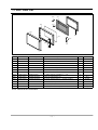
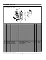
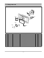
7. Exploded Views and Parts List
7-1 Exploded Views
X024
M002
X038
M003
M001
M016
X021
W003
M005
M013
X022
M058
M095
M113
M008
M010
M011
X004
M053
M015
M009
P024
W006
M012
M019
W002
M017
P129
W024
M023
H018
M054
M029
B018
M036
M051
B006
T010
T009
M049
B011
B002
M048
M035
B010
T001
M038
M039
B001
M037
T017
M040
M034
M041
MM104
MM103
M043
MM105
M044
M047
M046
ڈٻڐڌٻڈ
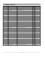
7-2 Main Parts List -
S.N.A : SERVICE NOT AVAILABLE
No.
Code No.
Description
B001
B002
B006
B010
B011
B018
M001
M001
M002
M003
M005
M008
M009
M010
M011
M012
M013
M015
M016
M017
M019
M023
H018
M029
M034
M035
M036
M037
M038
M039
M040
M041
M043
M044
M046
M047
M048
M049
M051
M053
M054
M058
M095
M113
P024
P129
T001
T009
T010
T017
W002
W003
W006
W024
X004
X021
X022
X024
X038
3405-001034
3405-001032
DE72-00137B
DE66-00093B
DE66-00094B
DE96-00120H
DE70-00185N
DE70-00185Q
DE63-90035H
DE61-00438A
DE61-70060A
DE63-20017A
DE60-40009B
DE61-50021A
DE61-50347A
DE61-50027B
DE61-50570C
DE39-00022B
DE63-00148A
DE96-00011A
3601-001197
DE31-00001D
DE31-90020A
DE47-20009A
DE67-00187A
OM75P(31)ERHN
4713-001046
DE71-60016D
DE26-00080B
2501-001015
DE61-50106A
DE91-70065A
DE91-70061A
DE26-00101A
DE60-60025A
DE61-40065A
DE80-00024E
DE31-10170A
DE71-00015A
DE97-00441A
DE32-10013A
DE65-20014A
DE47-00001A
DE61-30006A
DE32-60013A
DE61-50301A
DE74-20015G
DE97-00136B
DE97-00136E
DE92-90189T
DE96-00292A
DE96-00296A
DE39-40409A
DE96-00315A
DE99-00242J
DE70-00384A
DE75-00034A
DE63-00189A
DE75-00037A
SWITCH-MICRO
SWITCH-MICRO
LATCH-BODY
LEVER-SWITCH(A)
LEVER-SWITCH(B)
ASSY BODY LATCH
PANEL-OUTER
PANEL-OUTER
CUSHION-RUBBER
BRACKET-UPPER
SPRING-PLATE
GASKET-HEATER
WASHER-TEFLON
BRACKET-FLANGE
BRACKET-EARTH
BRACKET-HEATER
BRACKET-AIR GUIDE
ASSY POWER CORD
COVER-BACK
ASSY NOISE FILTER
FUSE-CARTRIDGE
MOTOR FAN
BLADE-FAN
THERMOSTAT
COUPLER
ASSY-MAGNETRON
LAMP-INCANDESCENT
COVER-AIR
TRANS H.V
C-OIL
BRACKET-HVC
ASSY-HVD
ASSY-H.V.FUSE
TRANS L.V
PIN-FOOT
FOOT
BASE-PLATE
MOTOR SYNCHRONOUS
COVER-CEILING
ASSY-GUIDE AIR
SENSOR THERMISTOR
CABLE CLAMP
HEATER
SUPPORT-HEATER
SENSOR GAS
BRACKET-COVER
TRAY-COOKING
ASSY-WIRE RACK
ASSY-WIRE RACK
ASSY-GUIDE ROLLER
ASSY-WIRE HARNESS-A
ASSY-WIRE HARNESS-B
WIRE HARNESS-E
ASSY-WIRE HARNESS-SENSOR
ASSY-CLEAN WATER BOWL
PLATE-STEAM
BOWL-STEAM
COVER-STEAM BOWL
RACK-STEAM
Specification
125/250VAC,16A,200GF,SPST-N
125/250VAC,16A,200GF,SPDT
PG113R,NYLON,WHT,-,-,-,-,PG113R,NYLON,NTR,HANDLE,
PG113R,NYLON,NTR,HANDLE,
PG113R(TBMO/SIDE),NYLON
C115,SECC,T0.6,W405.7,L1090.
1.1 AQUA CONV,SECC,T0.6,-,-,PCM,
-,DFA20,T2,W190,L200,-,C115,SECC,T0.5,-,-,-,1.1-C
-,SK-5,T0.5,-,-,-,-,-,-,-,-,BRASS,T1.5,OD30.5,ID22.5
SLOT,ID22.2,OD28,T1.2,TEFL
-,SECC1,T0.8,32,32,-,-,BSS2-A,T1.0,W35,L43,MBGF
-,SECC,T1.0,W51,L55,CE945
CK95,SECC,T0.8,-,-,-,D
4819D,CK135,230V50Hz,-,-,-,-,C115,SECC,T0.5,-,-,-,-,-,1.1
SN-3WUA,250V15A,3W 15A
250V,15A,SLOW-BLOW,CERAMI
-,SMF-2D3EA,230V50Hz,-,M1D33CE
ALSTAR,T0.6,W250,L250,-,-,PW2N-520PB,160/60,250V/7.5A,H
CE1100,PPS(ESS840),-,-,-,OM75P(31)ERHN
240V,104mA,25W,ORG,-,CK95,NYLYN#66(TEFRON523),-,-,SHV-EURO2,230V,50HZ,2340V/3.5V
1.0uF,2100V,BK,35X54X80,20mm
-,SECC,T0.8,W31,L125.8,-,BMP28,SEMA,12KV,SUMI,THV060T-0800-H,5KV/0.80A,W
SLV-C115E,230V,50HZ,22V,7.5V,3
PP-JI350,BLK,-,-,-,-,-,-,PP,T2x22x17mm,BLK,-,-,C110/C115,SCP1,T0.6,-,-,-,NCM2LJ24Z702,ST-16F,220/
CE2933,-,T0.3,W114.2,L121.
CE1150/CE1160,SENSOR,-,PT-312-K2,-,-,-,-,-,-,-,-,NY-66,-,DA-6N
SHG-2933E,-,-,1300W(1250W),-,230V
-,ALUMINA,5G,2ND-W/P,-,-,
ST-MWO,-,-,-,-,-,-,SBHG1-A,RE-707GMS,-,-,-,
3RD-1.0,T6,1115G,HKS,-,-,-,
CK95,LOW-RACK,-,-,-,MG104WA,114,FOOT,VE-TYPE
JES1044,PPS 14.7DI,-,CE1115/XEF,CONVECTIO
CE1100/XEF,CONVECTIO
230V50HZ,M9G45,CTW,-,-,CE1150/XEF,CONV
CE1150R-S/BWT,SPS(LG SP2306FS)
C115,STS304,-,T0.5,-,-,-,-,C115,HEAT-RESISTING PP,-,-,-,
C115,STS304,T0.5,-,-,-,
C110/C115,PP(HI831),STEAM BOW
ڈٻڑڌٻڈ
Q'ty
Remark
1
1
1
1
1
1
1
1
1
1
1
1
1
1
1
1
1
1
1
1
1
1
1
1
1
1
1
1
1
1
1
1
1
1
4
4
1
1
1
1
1
1
1
1
1
1
1
1
1
1
1
1
1
1
1
1
1
1
1
DOOR
WHT
SILVER
P/CORD
7-3 Door Parts List
D009
D004
D010
D002
D049
D006
D024
D007
D026
D011
D019
No.
Code No.
D002
DE64-00776A
DOOR-A
Description
C115,PC LEXAN#141,WHT,1.1 CONV,-,
Specification
1
D004
DE94-00428E
ASSY DOOR-E
1.1 AQUA CONV,SEALANT,-
1
D006
DE64-01043A
DOOR-C
CE1100,PBT,-,-,-,-,BLK,1.1 AQUA C
1
D007
DE61-00193A
SPRING-KEY
MW1255,HSWR,PI0.6,-,D5.5,L19,
1
D009
DE61-00246A
HINGE-DOOR UPPER
MW8103SS,SCP1,T2.0,-,-,
1
D010
DE61-00247A
HINGE-DOOR LOWER
MW8103SS,SCP1,T2.0,-,-,
1
D011
DE64-00690A
KEY-DOOR
TBMO-EURO,NYLON#66,-,-,BLK,-,SI
1
D019
DE64-01067B
HANDLE-DOOR
1.1 AQUA CONV,PC LEXAN#141,-,-,-,-,SIL
2
D024
DE64-00984A
SCREEN-DOOR(B)
C100/C115,TEMP-GLASS,T3.2
1
WHT
D024
DE64-00984B
SCREEN-DOOR(B)
CE1150-SL,TEMP-GLASS,3.2,-,-,-,SILVER,1.1AQUA
1
SILVER
D026
DE64-00980A
HANDLE-COVER
C110/C115,PP(HI831),CONV-1.1,STEAM BOWL
1
D049
-
ASSY DOOR
CE1110/XEU,WHT,SEUK
1
D049
-
ASSY DOOR
CE1150-SL,PC LEXAN#141,-,-,-,-,SILVER,1.1 AQUA CON
S.N.A : SERVICE NOT AVAILABLE
ڈٻڒڌٻڈ
Q'ty
Remark
WHT(S.N.A)
SILVER(S.N.A)
7-4 Control Parts List
ASSY- CONTROL BOX - C082
C009
C001
C005
C108
C035
C011
C071
C003
C010
C084
C028
C012
C019
C107
C094
C013
No.
Code No.
Description
Q'ty
Remark
C001
DE94-00913C
ASSY CONTROL-PANEL
-,CE1150R/BWT,WHT,RUSSIA
Specification
1
WHT
C001
DE94-00913D
ASSY CONTROL-PANEL
-,CE1150R-SL/BWT,SILVER,RUSSIA
1
SILVER
C003
RC-CE1150-01
ASSY PCB PARTS
CE1151T/XEF,230V50HZ
1
C005
DE64-00779C
CONTROL-PANEL
CE1150R/BWT,PC LEXAN#141,-,-,-,-,WHT,
1
WHT
C005
DE64-00779J
CONTROL-PANEL
CE1150R-S/BWT,PC LEXAN#141,-,-,-,-,PURE-SILVER,
1
SILVER
C009
DE64-00780A
WINDOW-DISPLAY
C115,SAN(CR5381),SMG,1.1
1
C010
DE64-00789B
BUTTON-SELECT
CE1150,PC LEXAN#141,-,-,WH
1
WHT
C010
DE64-00789D
BUTTON-SELECT
CE1150-SL,PC LEXAN#141,-,-,SILVER,-
1
SILVER
C011
DE64-00781A
BUTTON-SELECT(A)
C115,PC LEXAN#141,1.1 C
1
WHT
C011
DE64-00781B
BUTTON-SELECT(A)
CE1150-SL,PC LEXAN#141,-,-,SILVER,-
1
SILVER
C012
DE64-00782A
BUTTON-SELECT(B)
C115,PC LEXAN#141,1.1 C
1
WHT
C012
DE64-00782B
BUTTON-SELECT(B)
CE1150-SL,PC LEXAN#141,-,-,SILVER,-
1
SILVER
C013
DE64-00783A
BUTTON-SELECT(C)
C115,PC LEXAN#141,1.1 C
2
WHT
C013
DE64-00783B
BUTTON-SELECT(C)
CE1150-SL,PC LEXAN#141,-,-,SILVER,-
2
SILVER
C019
DE64-00789F
BUTTON-START
CE1150R/BWT,PC LEXAN#141,-,-,WHITE,-
1
WHT
C019
DE64-00789E
BUTTON-START
CE11505-S/BWT,PC,-,-,SIL,1.1 AQUA CONVECTION
1
SILVER
C028
DE64-00787A
KNOB-COVER
C115,PC LEXAN#141,1.1 CONV,-,
2
WHT
C028
DE64-00787B
KNOB-COVER
CE1150-SL,PC LEXAN#141,-,-,-,-,SILVER,-,-
2
SILVER
C035
DE64-00946A
BUTTON-CLOCK
C115,PC LEXAN#141,-,-,-,-
1
C071
DE63-00150A
COVER-LED
C115,ABS CLEAR,1.1 CONV,-,-,-,
1
C082
-
ASSY CONTROL-BOX
-,CE1150R/BWT,WHT,RUSSIA
1
WHT(S.N.A)
C082
-
ASSY CONTROL-BOX
-,CE1150R-SL/BWT,SILVER,RUSSIA
1
SILVER(S.N.A)
C084
DE96-00318A
ASSY-KEY MODULE
DKM-CE1150,KEY-MODULE
1
C094
DE69-00351A
BAND-BUTTON DIAL
FC139ST(FBI),SILICON RU
2
C107
DE01-00141A
FILM-BOARD
-,1.1AQUA CONV.,PET,T0.1,-,-,
1
C108
DE01-00142A
FILM-WINDOW
-,1.1AQUA CONV.,PET,T0.2,-,-
1
S.N.A : SERVICE NOT AVAILABLE
ڈٻړڌٻڈ
7-5 Casing Parts List
H001
H002
H011
H013
H004
H012
H005
H002
H017
H010
H003
H007
H008
No.
Code No.
Description
Specification
H001
DE31-10171A
MOTOR CONVECTION
SMC-105EA,230V/50HZ,280
1
H002
DE31-90019A
BLADE-FAN
SECC,T0.6,-,-,-,-,-
1
H002
DE31-90020A
BLADE-FAN
ALSTAR,T0.6,W250,L250,-,-,-
1
H003
DE47-70077A
HEATER-CONVECTION
SHC-118E1,-,-,1680W,-,
1
H004
DE61-50484A
BRACKET-HEATER
-,STS430,T0.8,W27.2,L26,C
2
H005
DE97-00393A
ASSY-COVER CASING
C110,1.1CU.FT,AQUA CON
1
H007
DE72-30016A
BUSH-MOTOR
-,MSWR3,L11.2,D5.6,RE-1300,-,
1
H008
DE60-40026B
WASHER-PLAIN
ID5.5,OD12,T1.0,SBC1,ZNC3,-
1
H010
DE60-30016A
NUT-FLANGE
M4,MSWR10,-,-,-,-,-,-,-
1
H011
DE60-40014B
WASHER-C MOTOR
M16,T1.0,SECC,ZNC3,-,-,-,
1
H012
DE61-50490A
BRACKET-TCO
-,SECC1,T0.6,34,58,-,-
1
H013
DE47-20009A
THERMOSTAT
PW2N-520PB,160/60,250V/7.5A,H
1
ڈٻڔڌٻڈ
Q'ty
Remark
SENSOR
7-6 Standard Parts List
Code No.
Description
Specification
Q'ty
Remark
DE60-20063A
BOLT-FLANGE
M4,10,ZPC3,YEL,MSWR,-,-,-,-
4
HING-L/U
DE60-30016A
NUT-FLANGE
M4,MSWR10,-,-,-,-,-,-,-
1
SENSOR
DE60-30016B
NUT-FLANGE
M4,MSWR10,FEFN,-,-,-,-,-,-
3
DE60-10082H
SCREW-A
-,-,-,-,2S-4X12,TOOTHED,-,-,-,-
5
P-OUTER
DE60-10018A
SCREW-ASSY MACHINE
-,WS,MSWR10,SN1,PH,M4X0.7P,-,8,-,-
2
B-EARTH
DE60-10098A
SCREW-ASSY TAP TITE
-,GLD,SWRCH18A,ZPC2,PH,TC,-,M4X8,WT,-
2
M-DRIVE
DE60-10045A
SCREW-TAP PH
-,-,FEFZY,-,PH,M3,-,L6,-,-
2
DE60-10052A
SCREW-TAP PH
-,-,FEFZY,-,PH,M4,-,L8,-,-
2
DE60-10045A
SCREW-TAP PH
-,-,FEFZY,-,PH,M3,-,L6,-,-
1
-
DE60-10088A
SCREW-TAP PH
-,-,FEFZY,PLAIN,PH,M3,-,L8,-,-
9
-
DE60-10070A
SCREW-TAP TH
-,-,FEFZY,2-SLOT,TH,M4,-,L12,-,-
2
A-A-LEFT
DE60-10070A
SCREW-TAP TH
-,-,FEFZY,2-SLOT,TH,M4,-,L12,-,-
4
A-C-BACK
DE60-10070A
SCREW-TAP TH
-,-,FEFZY,2-SLOT,TH,M4,-,L12,-,-
3
A-CASING
DE60-10070A
SCREW-TAP TH
-,-,FEFZY,2-SLOT,TH,M4,-,L12,-,-
1
A-THERMO-G
DE60-10070A
SCREW-TAP TH
-,-,FEFZY,2-SLOT,TH,M4,-,L12,-,-
1
B-A-GUIDE
DE60-10070A
SCREW-TAP TH
-,-,FEFZY,2-SLOT,TH,M4,-,L12,-,-
2
B-LATCH
DE60-10070A
SCREW-TAP TH
-,-,FEFZY,2-SLOT,TH,M4,-,L12,-,-
1
B-UPPER
DE60-10070A
SCREW-TAP TH
-,-,FEFZY,2-SLOT,TH,M4,-,L12,-,-
1
C-AIR
DE60-10070A
SCREW-TAP TH
-,-,FEFZY,2-SLOT,TH,M4,-,L12,-,-
2
C-BOX
DE60-10070A
SCREW-TAP TH
-,-,FEFZY,2-SLOT,TH,M4,-,L12,-,-
2
M-FAN
DE60-10122A
SCREW-TAP TH
-,-,FE,FN,TAP,TH,-,2-4X8,-,-
3
B-HEATER
DE60-10122A
SCREW-TAP TH
-,-,FE,FN,TAP,TH,-,2-4X8,-,-
2
C-CEILING
DE60-10122A
SCREW-TAP TH
-,-,FE,FN,TAP,TH,-,2-4X8,-,-
1
SENSOR
DE60-10122A
SCREW-TAP TH
-,-,FE,FN,TAP,TH,-,2-4X8,-,-
3
B-C-MOTOR
DE60-10122A
SCREW-TAP TH
-,-,FE,FN,TAP,TH,-,2-4X8,-,-
2
BKT-HEATER
DE60-10122A
SCREW-TAP TH
-,-,FE,FN,TAP,TH,-,2-4X8,-,-
4
CV-CAS
DE60-10012A
SCREW-TAP TITE
-,SWR10,M4,L10,TH,+,-,3,ZPC2,-
1
A-N-FILTER
DE60-10012A
SCREW-TAP TITE
-,SWR10,M4,L10,TH,+,-,3,ZPC2,-
1
A-P-CORD
DE60-10012A
SCREW-TAP TITE
-,SWR10,M4,L10,TH,+,-,3,ZPC2,-
3
B-PLATE
DE60-10012A
SCREW-TAP TITE
-,SWR10,M4,L10,TH,+,-,3,ZPC2,-
1
C-B-EARTH
DE60-10012A
SCREW-TAP TITE
-,SWR10,M4,L10,TH,+,-,3,ZPC2,-
1
M-D-CONVE
DE60-10012A
SCREW-TAP TITE
-,SWR10,M4,L10,TH,+,-,3,ZPC2,-
1
B-T-MOTOR
DE60-10034A
SCREW-TH
-,-,L10,STS304,TH,+,-,M4,-,-
1
SENSOR
DE60-10080B
SCREW-WASHER
-,2S,SWRCH18A,ZP2,PH,PI5,-,L10,-,-
4
MAGNETRON
DE60-10080B
SCREW-WASHER
-,2S,SWRCH18A,ZP2,PH,PI5,-,L10,-,-
4
TRANS-HV
ڈٻڋڍٻڈ
-
A-A-RIGHT
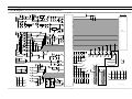
8.P.C.B Diagrams
8-1 P.C.B Diagrams
( This Document can not be used without Samsung's authorization. )
IC1
IN
C22
8
75
40
74
39
P16
73
38
P15
72
37
P14
71
36
P13
70
35
P12
69
34
P11
1
23
F11 F12 F13
0V
470uF
3
D01
GF1G
DGND
R04
3.9K
ZD3
ZMM55CV1
0.02nF
C01
100nF
XTL1
8MHz
4
5
C03
-34V
DGND
+24V
IC7
KIA7824AF OUT
IN
78L05
OUT
DGND
DGND
DGND
C24
100nF
C06
100uF
GND
R09
2K
DGND
40
68
33
P10
39
67
32
P9
66
31
P8
65
30
P7
ELM7533CBA-S
IC2
IN
DGND
OUT
GND
C07
47uF
C09
100nF
C08
100nF
10
64
29
P6
38
63
28
P5
13
62
27
P4
7
61
26
P3
CN2
SMW250-03AV_RED
C/MOTOR
1
RY1
D05
MM4148
+24V
DGND
TR1
KRC246
FTR-F3AA024E
3
DGND
5V-1
DGND
DGND
60
25
P2
59
24
P1
58
23
1G
57
22
2G
56
21
3G
55
20
4G
54
19
5G
53
18
6G
1K
52
17
7G
C23
4.7uF
51
16
8G
DGND
+5V
DGND
F/MOTOR
RY2
TR2
KRC246
FTR-F3AA024E
RY3
D07
MM4148
FTR-F3AA024E
C/HEATER
FUSE1
FH-51H
R40
26.1K
36
2
2
D08
MM4148
-
R45
IC5
KIA358F
3
TR3
KRC246
ZMM55CV1
DGND
3
1
R42
200K
RY4
R41
19.1K
4
DGND
T/TABLE
ZD4
CN11
SMW250-04V_RED
D06
MM4148
R43
100K
1
+
R44
100K
VCC=+10V,GND=DGND
0V
TR4
KRC246
FTR-JRJC024W
35
DGND
GRILL
RY5
D09
MM4148
INRUSH
RY6
D10
MM4148
TR6
KRC246
FTR-F3AA024E
PTC1
270M
POWER
1
RY7
D11
MM4148
15
9G
49
14
10G
48
13
11G
47
12
12G
2
46
11
13G
80
45
10
14G
1
44
9
15G
4
43
8
16G
5
42
7
17G
79
41
6
18G
3
TR7
KRC246
FTR-JRJB024W
3
DGND
TR5
KRC246
FTR-JRJC024W
PTC2
270M
DGND
50
6
+5V
+24V
D13
GF1G
C27
22nF
D12
MM4148
R15
R14
D17
MM4148
D18
MM4148
D19
MM4148
D20
MM4148
R46
47K
R47
47K
R48
47K
R49
47K
R50
47K
R51
47K
10K
TR18
KRC246
2K
C14
1nF
R25
47K
C15
1nF
R26
47K
C16
1nF
R13
C28
4.7uF
CN3
SMW250-07AV_RED
10K
TR9
KRC246
C11
100nF
C12
100nF
NET13
34
DGND
DGND
DGND
DGND
DGND
2
DGND
NET13
DGND
DGND
3
DGND
DGND
DGND
33
R16
R52
47K
DGND
+24V
1
MODEL
OPTION
D21
MM4148
DGND
R24
47K
25
FTR-F3AA024E
D16
MM4148
NET20
7
RY8
D15
MM4148
+5V
TR17
KRA226
5
MAIN
DGND
OJ1
CE1160
NET13
NET12
26
OJ2
3.9K
5
+5V
6
CN4
SMW250-06V(WHT)
+5V
C25
32
NET20
NET11
D14
R18
27
100nF
R21
U.S.A-OPTION
R20
R19
1K
10K
NET6
NET10
30
NET9
19
TR11
KRA226
NET2
BZ1
CBE2220BA
220
1
31
DGND
R22
ZNR1
10D471
3
TR10
KRA226
220
3
1
DGND
NET1
CN9
YW396-03AV(WHT)
MM4148
100K
+24V
DGND
TR16
KRC246
+5V
29
TR12
KRA226
NET4
NET5
NET6
R37
220
TR13
KRC246
LED1
LED2
LED5
220
NET1
LED3
+5V
TR14
KRC246
R54
2K
R39
R56
2K
LED6
220
TR15
KRC246
NET2
R57
47K
DGND
LED4
13
NET9
12
22
NET10
11
NET10
11
21
NET11
10
NET11
10
NET12
9
NET12
9
NET13
8
NET13
8
NET14
7
NET14
7
NET15
6
NET15
6
NET16
5
NET16
5
NET17
4
NET17
4
15
NET18
3
NET18
3
17
NET19
2
NET19
2
37
NET20
1
NET20
1
28
12
77
DGND
DGND
15
12
LED7
NET3
16
NET9
14
CN12
SMW250-03V_RED
FCZ12516HS-16A00
CN7
*
NET1
14
NET7
C17
1nF
R28
47K
C18
1nF
R29
47K
C19
1nF
R30
47K
C20
1nF
R53
1K
3
R55
47K
+5V
NET8
R27
47K
C26
100nF
16
13
1
2
17
NET1
NET8
+5V
NET6
NET2
11
76
DGND
ڈٻڌڍٻڈ
OJ3
CE1141
T/C MODEL OPTION
NET7
18
NET5
18
14
20
R38
19
NET3
NET7
23
NET4
20
NET4
NET11
15
24
220
CN6
FCZ12511HS-21A00
21
NET5
NET8
R23
NET3
SW1
JTS1230US
NET12
R17
4.7K
NET20
C13
1uF
NET19
4
CN10
YW396-03AV(WHT)
5
DSP1
HNM-17LS01
NET15
DGND
0.02nF
NC
NET17
DGND
DGND
9
DGND
IC4
C21
1000uF
GND
DGND
NET18
C05
470uF
DGND
+5V
42 43 44
F21 F22 F23
P17
NET14
IN
DGND
D22
GS1G
+10V
NET15
D03
GF1G
C04
47uF
R05
20K
R60
47K
R59
47K
78
C02
2
D02
GF1G
R58
47K
16
1K
GND
MMSZ5232B
NET16
470
ZD1
1
NET17
R02
R03
IC6
KIA7805AF OUT
NET18
470
NET19
R01
F2
F1
BD1
DF06S
CN1
SMW250-05V_WHT
-34V
TMP87PM74F
5V-1
-34V
NET16
F2
F1
SW4
SW7
SW10 SW13
SW2
SW5
SW8
SW11 SW14
SW16
SW6
SW9
SW12 SW15
SW3
NET13
NET12
NET11
DGND
RC-C115-00
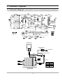
9. Schematic Diagrams
9-1 Schematic Diagrams
( This Document can not be used without Samsung's authorization. )
MAGNETRON
HIGH VOLTAGE
DIODE
FA
TO CHASSIS
F
HIGH VOLTAGE CAPACITOR
RED
RED
RED
H.V.FUSE
BLK
WHT
RED
HIGH VOLTAGE
TRANSFORMER
ڈٻڎڍٻڈ
SYMBOL
BRN
BLK
RED
BLU
COLOR
BROWN
BLACK
RED
BLUE
8-2 P.C.B Parts List
Code No.
Description
Specification
Q'ty
Remark
3501-001062 RELAY-POWER
24VDC,523.2MW,16000MA,1FORMA,15MS,10MS
1
RY7
3501-001068 RELAY-POWER
24VDC,523MW,16000MA,1FORMA,15MS,10MS
1
RY4
3501-001068 RELAY-POWER
24VDC,523MW,16000MA,1FORMA,15MS,10MS
1
RY5
3501-001155 RELAY-MINIATURE
24VDC,200MW,3000MA,1FORMA,10MS,10MS
5
RY1,RY2,RY3,RY6,RY8
3601-001126 FUSE-CARTRIDGE
250V,1.6A,FAST-ACTING,CERAMIC,5x20mm
1
FUSE1
3708-000219 CONNECTOR-FPC/FFC/PIC
21P,1.25MM,STRAIGHT,SN,ZIF,-,SINGLE
1
CN6
DE07-00060A VF DISPLAY
HNM-17LS01,HNM-17LS01,90*40*9.0,1/18,ND17,NS16
1
DSP1
DE09-00361A IC MICOM
TMP87CM74F-5BE0,CE1150R-SL/BWT,80PIN,+5V,8Mhz,
1
IC1
DE30-20016A BUZZER
CBE2220BA,STICK,-,-,-,-,-,-,-
1
BZ1
DE47-40024A HOLDER-FUSE
FH-51H,7.5A,-,-,-,-,-
1
FUSE1
DE61-00504A HOLDER-DIGITRON
NEW-WAVE,PP,-,-,-,BLK,-
1
DSP1
0401-001083 DIODE-SWITCHING
MM4148,100V,150MA,LL-34,TP
16
D05~D12,D14~21
0402-001080 DIODE-RECTIFIER
GF1G,400V,1A,DO,TP
5
D01~D03,D13,D22
0402-001298 DIODE-BRIDGE
DF06S,600V,1A,SMD-4,TP
1
BD1
0403-000507 DIODE-ZENER
MMSZ5232B,5.6V,5%,500mW,MELF,T
1
ZD1
0403-001288 DIODE-ZENER
ZMM55C5V1,4.8-5.4V,500MW,LL-34,TP
2
ZD3,ZD4
0504-001008 TR-DIGITAL
RN2427,PNP,200MW,2.2K/10K,SOT-23,TP
4
TR10~TR12,TR17
0504-001080 TR-DIGITAL
KRC246S,NPN,200mW,2.2K/10K,SOT-23,TP
13
TR1~TR7,TR9,TR13~16,TR18
1201-000167 IC-OP AMP
KA358,SOP,TP,8P,150MIL,DUAL,100V/MV,PLASTIC,
1
IC5
1203-001037 IC-POSI.FIXED REG.
78L05,SOT-89,3P,185MIL,PLASTIC
1
IC4
1203-002835 IC-POSI.FIXED REG.
KIA7805AF,DPAK,3P,6.6X6.1MM,PLASTIC,4.8V/
1
IC6
1203-002836 IC-POSI.FIXED REG.
KIA7824AF,DPAK,3P,6.6X6.1MM,PLASTIC,23/25V
1
IC7
1203-002876 IC-VOL. DETECTOR
ELM7533CBA-S,SOT-23,3P,2.9X1.5MM,PLASTIC
1
IC2
1404-000230 THERMISTOR-PTC
27ohm,20%,-,265V,1.5A,360mA,BK
2
PTC1,PTC2
2007-000033 R-CHIP
0ohm,5%,1/4W,TP,3216
16
J2~J7,J9,J12~20
2007-000277 R-CHIP
100Kohm,1%,1/8W,TP,2012
2
R18,R43
2007-000282 R-CHIP
100Kohm,5%,1/8W,TP,2012
1
R44
2007-000300 R-CHIP
10Kohm,5%,1/8W,TP,2012
3
R13,R14,R19
2007-000468 R-CHIP
1Kohm,5%,1/8W,TP,2012
3
R03,R20,R45
2007-000532 R-CHIP
200Kohm,5%,1/8W,TP,2012
1
R42
2007-000546 R-CHIP
20Kohm,5%,1/8W,TP,2012
1
R05
2007-000572 R-CHIP
220ohm,5%,1/8W,TP,2012
6
R21~R23,R37~R39
2007-000671 R-CHIP
2Kohm,5%,1/8W,TP,2012
2
R09,R15
2007-000710 R-CHIP
3.9Kohm,5%,1/8W,TP,2012
2
R04,R16
2007-000868 R-CHIP
4.7Kohm,1%,1/8W,TP,2012
1
R17
2007-000931 R-CHIP
470ohm,5%,1/8W,TP,2012
2
R01,R02
2007-000941 R-CHIP
47Kohm,5%,1/8W,TP,2012
19
R24~R30,R46~R52,R55,R57~R60
2007-001262 R-CHIP
19.1Kohm,1%,1/8W,TP,2012
1
R41
2007-007219 R-CHIP
26.1Kohm,1%,1/8W,TP,2012
1
R40
2203-000192 C-CER,CHIP
100nF,+80-20%,50V,Y5V,TP,2012,
7
C01,C08,C09,C11,C12,C24,C25
2203-000444 C-CER,CHIP
1nF,10%,50V,X7R,TP,2012,-
7
C14~C20
2203-000555 C-CER,CHIP
0.02NF,5%,50V,C0G,TP,2012
1
C02,C03
2203-000889 C-CER,CHIP
4.7nF,10%,50V,X7R,TP,2012
1
C27
2401-000037 C-AL
470uF,20%,16V,GP,TP,8x11.5,5
1
C22
2401-000151 C-AL
1000uF,20%,25V,GP,TP,10x20,5
1
C21
2401-000244 C-AL
100uF,20%,10V,GP,TP,6.3x7,5
1
C06
2401-001428 C-AL
470uF,20%,50V,GP,TP,10x20,5
1
C05
2401-001573 C-AL
47uF,20%,50V,GP,TP,6.3x11,2.5
1
C04,C07
2401-002075 C-AL
4.7uF,20%,50V,GP,TP,5x11,5
1
C23
2404-000151 C-TA,CHIP
1uF,20%,16V,-,TP,3216
1
C13
2404-000232 C-TA,CHIP
4.7uF,20%,10V,-,TP,3216
1
C28
2801-003933 CRYSTAL-UNIT
8MHz,50ppm,28-AAA,12pF,70ohm,TP
1
XTL1
3404-001129 SWITCH-TACT
12VDC,50mA,160gf,6.6x6.6x7mm,-
1
SW1
3711-000939 CONNECTOR-HEADER
BOX,4P,1R,2.5mm,STRAIGHT,SN
1
CN11
3711-000999 CONNECTOR-HEADER
BOX,5P,1R,2.5mm,STRAIGHT,SN
1
CN1
3711-001038 CONNECTOR-HEADER
BOX,6P,1R,2.5mm,STRAIGHT,SN
1
CN4
3711-004143 CONNECTOR-HEADER
BOX,2P,1R,5MM,STRAIGHT,SN,RED
1
CN2
3711-004200 CONNECTOR-HEADER
BOX,4P/7P,1R,2.5MM,STRAIGHT,SN,RED
1
CN3
ڈٻڍڍٻڈ