1
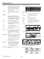
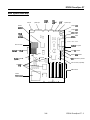
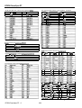
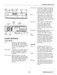
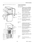
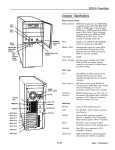
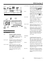
EPSON PowerSpan DT
hard disk
diskette
diskette
drive
power drive
release
aocess light light
access light button
AC output
socket
\
/
power
supply fan
Built-m 16KB of internal write-back cache
in the Pentium microprocessor; 256KB of
secondary, direct-mapped, write-through
cache on eight 32KB x 8,15ns SRAMs on
the main system board; tag and control
logic on the 82434LX PCMC core chip
ROM
128KB system and video BIOS located on
a flash EEPROM device; contains Setup
program code, power-on self test code,
update recovery code, and the PC1 board
auto-configuration utility; upgradable and
write-protectable
Video RAM
1MB of standard video RAM providing
video resolutions up to 1024 x 768 in
256 colors; expandable to 2MB by
installing eight 256KB x 4, 60ns ZIP
VRAMs on the main system board to
provide resolutions up to 1280 x 1024 in
256 colors
Shadow RAM
Supports shadowing of system and video
BIOS ROM, and ROM located on
expansion board adapters, into RAM
Clock/
calendar
Real-time clock, calendar, and 128-byte
CMOS RAM (114 bytes for general
purpose non-volatile CMOS RAM and
14 bytes for clock and control registers)
on socketed DS12887 device; integrated
battery and oscillator; CMOS RAM
clearable and resettable using the Setup
program or by setting a main system
board jumper
power
button
Mankfller
pSIl&
voltage
selector
switch
Cache memory
expansion
card slots
/I
KEYtiD / &,, , \
MOUSE
COM2
/
AC input
socket
\
LPT
Computer Specifications
CPU and Memory
CPU
System speed
Intel Pentium 60 MHz microprocessor;
backward compatible with 8086, 80286,
i386, and 486 CPUs; supports read and
write burst mode bus cycles; built-in 16KB
write-back cache; integrated math
coprocessor
Controllers
High and low speeds available; high speed
is 60 MHz and low speed is simulated
8 MHz for compatibility; speed selection
through Setup program or keyboard
commands
System memory 8MB standard memory on two 4MB
SIMMs; expandable to 128MB using 1 MB,
2MB, 4MB, 8MB, 16MB, and 32MB SIMMs
(when readily available); SIMMs must be
32-bit or 36-bit, 72-pin, 70ns or faster,
tin-plated, fast-page mode, parity/no
parity type
3/94
Video
ATI 68800AX Mach32 local bus PCI
graphics accelerator; compatible with
MDA, CGA, Hercules Graphics, EGA, and
VGA video standards; supports normal
and enhanced video modes; supports
interlaced and non-interlaced monitors
Diskette
SMC FDC37C665 super I/O controller
with interface on the main system board
controls up to two diskette drives or one
diskette drive and one tape drive; 16-byte
data FIFO (first-in-first-out) with 2.88MB
diskette drive support
Hard disk
SMC FDC37C665 super I/O controller
with interface on the main system board
controls up to two IDE hard disk drives;
BIOS provides hard disk auto-sensing
function
EPSON PowerSpan DT - 1
EPSON PowerSpan DT
Parallel port
Serial ports
SMC FDC37C665 super I/O controller
provides multiple modes: standard (IBM
and Centronics compatible), enhanced
(EPP with bidirectional functions and
BIOS/driver support), and high speed
(ECP compatible)
Physical Characteristics
Dimension
Width
Depth
Height
Weight
SMC FDC37C665 super I/O controller
supports two RS-232C compatible serial
ports
Power Supply
Interfaces
Video
SVGA PCI local bus interface with
standard, 15-pin analog connector; VESA
compliant 8514/A feature connector on
main system board for auxiliary video
subsystem installed in an expansion slot
Parallel
Multimode, bidirectional parallel port
with 25-pin, D-shell connector
Serial
Two RS-232C compatible, programmable,
asynchronous serial ports with 9-pin,
D-shell connectors
Keyboard
PS/2 compatible mouse port with 6-pin,
mini DIN connector
Expansion slots
Five expansion slots on expansion board
riser card: one full-length, 16-bit ISA slot;
two half-length, 16-bit ISA slots; one
full-length PCI slot, and one half-length
PCI slot
Mass Storage
145 Watt, switchable voltage; maximum
power dissipation: 120 Watts
Input ranges
90 to 135 VAC and 180 to 265 VAC;
5O/60 Hz
AC input
current
5.0 Amps at 90 to 135 VAC;
3.0 Amps at 180 to 265 VAC
AC power
outlet
2.0 Amps maximum for 100 to 120 VAC;
1 Amp maximum for 200 to 240 VAC
Cables
Two to main system board; four to mass
storage devices
DC output
Maximum
continuous
DC voltage current
18.0 Amps
+5v
0.3 Amp
-5v
4.2 Am[ x3
+12v
1 0.3 Amp
I-12v
Internal bays: one 3.5-inch, one-inch high
bay (for the standard diskette drive) and
one 3.5-inch, 1.6-inch high bay for an
optional internal drive in the drive carrier
load
2.5 Amps
OArrp
1 0.5 Amp
lOAmp
IO.044 Amp (10%)
IO Amp (5%)
Expansion board power limits
Beard type
4%
PCI (57.6W per -
slot)
Detachable, two-position height; 101 or
102 sculpted keys; countrydependent
main typewriter keyboard; numeric/
cursor control keypad; four-key cursor
control keypad; 12 function keys
ISA (16bit;
66 W per slot)
Maximum current per board
1+5v
I +12v
I -12v
15Amp.s 1500ma 1100ma
+3.3v
17.6Amps
1.5Amps 4.5 Amps l.SAmps 1.5 Amps -
To avoid damage to the system board or power supply, do
not exceed a total of 145 Watts power draw.
Setup Program Stored in ROM; accessible by pressing F1
during boot
EPSON PowerSpan DT - 2
Peak current:
15eeccnds
18.0 Amps
0.3 Anp
1 6.0 Amps
1 0.3 Amp
Power consumption
Externally accessible bays: Two 5.25-inch,
half-height bays (can be used as one
5.25-inch, full-height bay)
Keyboard
Type
PS/2 compatible keyboard port with
6-pin, mini DIN connector
Mouse
Specification
17.2 inches (43.7 cm)
16.2 inches (41.1 cm)
4.3 inches (11.0 cm)
20 lb (9.1 kg) without drives or keyboard
Environmental Requirements
3/94
EPSON PowerSpan DT
Main System Board Map
VGA port
parallel port
WM2
sertai port
COMl
serial
port
mouse
pofi
keyboard port
jumper J13H3
Mach32
sraphi=
controller
jumper J13Hl
\
VFW4
expansion
jumperJl2Hi
prtmary power
- connector
sockets \
-- real-time dock
VESA connector
auxiliary 3.3 V power
connector
standatd 1 MB ‘/RAM
- super I/O controller
4
\ diskette drive interface
PCMM controller
(inoperable)
L
-r
core chp set
6
\
1
IDE1 (IDE/ISA-bus) interface
IDE2 connector (inoperable)
- SIMM sockets
Pentium
micmproc8ssor
-
3/94
EPSON PowerSpan DT - 3
EPSON PowerSpan DT
System board components and connectors
SIMM lnstallation
Your computer comes with 8MB of memory on two 4MB
SIMMs. You can increase the memory up to 128MB using
1MB, 2MB, 4MB, 8MB, 16MB, and 32MB SIMMs (when
readily available).
Jl3Gl
Jl3Hl
1 J13Hl
Jl3H3
Jl3H3
J13H5
JIDAI
JIFI
JlF2
JlF3
JIG1
JIG2
JlHl
J3Al
J4F1, J4Gl
J4H1, J4H2
J7Al
J7Hl
J6Jl
J6J2
J9Fl
Jgfil
UiOB5, UIOCI
UloGl
UlaJl
U2Bl
The SIMM sockets are organized in two banks (Bank 0 and
Bank 1) consisting of two sockets each. You must install the
same type of SIMM in a bank.
j Mouse connector
I CMOS clear jurrper
j Password enable/disabfe jumper
Monitor jumper
Setup entry/write-protect jumper
Keyboard connector
VESA feature connector
Speaker
Reset
Ke-erLED
Hard disk drive LED
1 Turbo swftch
The SIMMs you install must be 32-bit or 36-bit, 72-pin, 70ns,
tin-plated, fast-page mode, parity/no parity DRAM. The
table below lists the 16MB and 32MB SIMMs that are
approved for use in your system. You can install these
SIMMs or their equivalents.
Manufacturer
Samsung
Samsung
Hitachi
I hb0LED
Auxiliary Ian
SIMM bank 1
SIMM bank 0
CPU clock speed jumper (DO NOT CHANGE SETTING)
FCI IDE connector (inoperabfe)
Diskette drive connecfor
AT IDE hard disk drive connector
Fflser card connector
Power connector
video VHAM upgrade sockets
BIOS
I FleaI-time clock
Processor
SIMM configurations
Main system board jumper settings
I
l
Upgrades
Jl3Hl
l-2
2-3
l
4-5
15-6
1 l-2
2-3 *
4-5
5-6
l
Jl3H3
l
l
Normal CMOS operation
Clear current CMOS settings to reset to the factory
default settings
Enable the current password
1 Disable the cum&password
1 Monochrome monitor Is installed
Color monitor Is instafled
Enable entry Into the Setup program
Disable entry into the Setup program
* Factory configuration
Factory setting
EPSON PowerSpan DT - 4
Part number
KM41 COOBJ-7
KMM5324000BG-7
HM5117400J7
The table below lists possible combinations of SIMMs you
can install; do not use any configuration other than one of
those listed in the table.
Jumper Settings
Jumper I
I
number Settings Function
Jl2Hl 1 l-2
1 Flaeh memory recovery mode; atfows recovery of the
defauit BIOS if it is corrupted dutlng an upgrade
2-3
Normal flash memory operation
4-5
Enable BIOS upgrades to tfte flash memory
5-6’
Write protect the flash memory to prevent BIOS
Description
16MB; with parity
16MB; no parity
32MB; with parity
3/94
EPSON PowerSpan DT
The table below lists the monitors that are directly supported
by the Mach32 accelerator.
Video Memory, Modes, and Monitors
Check the monitor documentation to see if its characteristics
match one of the listed types. If so, select that type in the
Mach32 installation program.
This system comes with 1MB of VRAM soldered on the main
system board. You can increase the video memory to 2MB by
installing eight VRAM ZIP chips (256KB x 4, 60ns, fast-page
mode). You must fill all eight sockets.
For EPSON monitors, see the second table for information on
the monitor type to select.
The table below lists the video modes supported by the
system.
If the monitor does not match any of these types, set up a
custom monitor.
Resolutions and colors
I
Mach32 monitor list
12MB
* Interlaced
EPSON monitor types
Hard Disk Drive Types
This system comes with a hard disk auto-sensing feature.
Some drives do not support the auto-sensing feature. If the
system does not correctly define your hard disk drive, you
can define up to two drive types in SETUP.
(1) bpp=bits per pbel: 4 bpp=l6 colofs, 6 bpp=256 colors,
16 bpp=65,000 colors, 24 bpp~l6.7 mlson colors
(2) 32 MHz setting
(3) 40 MHz setting
(4) Interlaced
3/94
EPSON PowerSpan DT - 5
EPSON PowerSpan DT
System Memory Map
Drive Option Information
Hard disk drive options for 1-inch IDE drives
Quantum
Western
Digital
flq$
i
&39&
I.?
0
z
Y
g
340
Connor
Parameters
4
4
Formattedcapacity
250
WV
Size, width x height 4 x 1
(in)
Weight (Ibs)
11.2
340
426.3
540
245
240
4x1
4x1
4x1
4x1
3.5x1 3 . 5 x
1.16
Il.16
Il.05
Cylinders
DiSkS
8
11.2
1695
2116
2366
2605
12
1 2
12
12
4
I
II.12
1016
2233 1 2233
2
2
12
4
13
14
Heads
4
4
4
62
63-95
63-106 72-114 44-67
56-96
56-Z
Rotational speed
(RPM)
&Afar size(KEt)
4542
4500
3606
4500
4306
3322
3322
64
64
32
266
256
64
126
Average seek time
(md
Encoding method
14
13
14
12
16
<I3
<I3
RLL
t,7
RLL
I,7
RLL
I,7
RLL
t,7
RLL 1,7
RLL
1.7
RLL
I,7
5.2 W
5.2 N
1010
9
1011
1011
55
1010
12
1011
1011
55
3.75W(3.75Wj5.12W(5.7W
I
I
695
10
0
695
55
I
I
655
16
0
655
63
I
I
626
16
0
626
63
(,.9W
10999W-7FFFFFF
FEO909-FFFFFF
19999&FDFFFF
FM)(x)-FFFFF
EEWGEFFFF
EDCW-EDFFF 4
II.12
Sectorspertrack
Power dissipation
b=k)
Logical parameters
Cylinders
Heads
Precomp zone
Landing zone
sectors
Address range
~hexadecimal)
723
13
none’
723
51
E5999-ECFFF
29KB
E9999-E7FFF
CSOOGDFFFF
32KB
96KB
Cm7FFF
32KB
BWWBFFFF 3 2 K B
BCNXCI-B7FFF 3 2 K B
I
1046
16
0
1046
63
SIZO
112MB
129KB
15232KB
94KB
9KB
K B
ACt999AFFFF
94KB
SFCWQFFFF
IKB
90999-QFBFF
999997FFFF
127KB
512KB
Description
Extended memory
System and video BIOS copy
Extended memory
System BIOS
Ftaeh boot bluck (available as HIMEM)
User ftash ama (avahabte as HIMEM if no
user information Is here)
Setup mugram (disable vh setup pm-boot
ontyfthis Gtion‘open to HIMEM)
Avakble Hi DOS
Avattabte Hi DOS memory (open to the ISA
VGA BtOS
VGA display msmuty (not avattabte to ISA
bus)
VGA & mono display memory (HIMEM with
QEMM not avattabte to the bus)
VGA display memory (not avahable to the
ISA bus)
Extended BIOS data (moveable bv QEMM
and 359MAX)
Extended conventional
Conventionat
System I/O Addresses
* S&sot 1 or none for the precony, value. If neither of these uptlons are
avahabte, aeled the maximum avahabte pmcomp value.
IDE hard disk drive jumper settings
* CS (cable selection) can be jumpered for any configuration. When CS is
used, the drive ts a master tf pin 28 is grounded and a stave If pin 28 Is not
grounded.
Diskette drive options
Parameters
Storage capacity
Size. width x height (in)
3.5’ 1.44MB TEAC FD-235HF
1474KB (fornuxtted)
3.5 x 1
Cylinders
60
0376-037F
03BCXXBF
03E943EF
03F9-03F5
1 OCF9
EPSON PowerSpan DT - 6
3/94
IParalk5lpott2
Onboard parattel port
serial port 3
floppy channel 1
1 Deb&o mode enable
EPSON PowerSpan DT
System I/O addresses (continued)
Serial port connector pin assignments (113El,]l3Fl)
I Address range 1
(hexadecimal) Description
C000-COFF
82434LX contiguratton registers
C2OO-C2FF
C3OO-C3FF
Pin
1
12
13
4
5
8237818 configuratton registers
Onboard ATI contlguration registers
System Board Interrupts
1 Signal name
1 Pin
I Signal name
Incn
1 DSR
ISWWItlIFITS
1 Serial Out-
II
17
18
IQ
1 10
I r-!-l-c
jDTF7
1 RI
1 GtiD
1 NC
1
Primary power connector pin assignments (JllHl)
Auxiliary (3.3V) power connector pin assignments (J9H1)
~
DMA Channels
DMA channel
0
1
2
3
4
I wetem resource
Open
Open; normally used for LAN
Diskette drive
IDE hard disk drive
Res8rved; cascade channel
1
Diskette drive connector pin assignments (J8]1)
Pin
I Signal name
1
3
5
7
9
ll
I Ground
I Ground
1 Key
Ground
Ground
Ground
I Pin
12
14
16
8
IO
12
I Signal name
1 FDHDIN
1 Resewed
1 FDEDIN
IndexMotor Enable ADrive !Ltelect B-
Connector Pin Assignments
Parallel port connector pin assignments (Jl3Cl)
3/94
EPSON PowerSpan DT - 7
EPSON PowerSpan DT
AT IDE hard disk drive connector pin assignments (1812)
Pin
1
3
Signal name
Reset IDE
Host Data 7
Pin
2
4
ISA expansion board connector pin assignments (continued)
Pin
825
B26
027
820
829
830
831
KEY
Signal name
Ground
Host Data 8
1 Slgnal name
1 IRQ3
IIBin
IA25
1 Signal name
ISA6
ITC
IA27
ISA4
IBALE
IA28
ISA3
vcc
osc
GND
A29
A30
A31
KEY
sA2
SAl
SAO
I
I
Stmker connector pin asshments trlF1)
Pin
1
1 Signal name
1 SPKR-DAT
3
4
No Connect
+!iu us-x?
PC1 expansion board connector pin assipnments
Auxiliary 12 Vfront fan connector pin assipnments (13Al)
Pin
1
2
3
-
-
”
SQnal
Pin
name
Sisld
P i n name
Pin
signal
name
Pin
SIgnal
name
Signal
name
Ground
+12v (fused)
Ground
ISA expansion board connector m’n assignments
All Reserved
B11 No Conned A42 GND
842
SERR-
Al2 GND
812 G N D
A43 PAR
043
3.3v
Al3 GND
813 G N D
A 4 4 AD15
844
CBEl-
Al9
I RGLWN~
A:10 I AD30
l Bl9 I vcc
1 A50 1 KEY
I, B! 50
I820 1 AD31
IA51 I KEY
I851 1 KEY
A21 1 3.3v
1821
IAD
1 A52 1 CBECL
1852
A22 /AD28
A23 1 AD26
I822
1 GND
1 A53 I3.3V
I853 1 AD7
I823 1 AD27
1 A54 1 AD6
824 A D 2 5
A55 AD4
055 AD5
A25 A D 2 4
825
3.3v
A68 GND
B56 AD3
AZ6 A D 2 2
(IDSEL)
826
CBES
A57 AD2
057 GND
A 2 7 3.3v
IAD
827 A D 2 3
I828 I GND
854
A58 ADO
1 A59 1 Vcc
t
3/94
AD8
A24 GND
IA28
EPSON PowerSpan DT - 8
/KEY
3.3V
858
An1
I859 I
Vcc
I
EPSON PowerSpan DT
VESA feature connector pin assignments (JlOAl) (continued)
PCI expansion board connector pin assignments (continued)
Signal
S4Ml
S@d
s4w
Pin name
Pin
A29 AD20
A30 GND
A 3 1 AD16
829 AD21
830 AD19
831 3.3v
name
Pln name
Pin name
A 6 0 SRECWA61 Vcc
A62 Vcc
B60 SACK64B61 v c c
862 V c c
Mouse and keyboard connector pin assignments (Jl3Gl and Jl3H5)
1 Pln
I Signal name
2
3
4
5
6
No connect
Ground
vcc (fused)
ClOCk
No connect
I
Error Messages
Beep codes
Number
of beeps Error message Description
Refresh Failure
1
The memory refresh cimutry on the main
Reset connector pin assignments (IlF2)
Pin
1
Signal name
RESET
2
Ground
2
3
Parity Error
Base 64KB
1 Memory Failure
4
I Timer Not
Operational
Power LED connector pin assianments (llF3)
Pin
1
2
3
4
5
5
6
I Signal name
ILEDPWR
7
Key
Ground
KEY LOCK
Ground
0
9
Hard disk drive LED connector pin assignments CJZGZ)
Pin
1
2
3
4
IO
Signal name
PULL UP 330
HiYl ACTNF-
11
1 Key
1 PULL UP 330
Turbo LED connector pin assiements (JlHl)
Pin
Signal name
1
2
PULL UP 330
system boafd is faulty
Parity error in the first 64KB of memory
Memotv failure in the first 64KB of memorv
Processor Etror
8042
- Gate
I Memory failure in the first 64KB of memory
or Tim& 1 on the main system board is not
functloning
The CPU generated an error
The keyboard controller may be bad: the
1 BIOS cannot switch to pm&d mode
I The CPU generated an exception interrupt
1~20 Failure
1 Processor
Exception
Interrupt Error
Dtspiav Mernorv
The system video adapter is either misstna
Re&&fte Err& or its memory is faulty; not a fataf error ROM Checksum The ROM checksum value does not match
Error
the value encoded in the BIOS
CMOS Shutdown The shutdown regtster for CMOS FtAM latfec
Register
ReadWrite Ermr
Cache
The external cache is faulty
ErronExtemal
Cache Bad
Error messapes
r
LEDTLRB&
Video monitor port connector pin assignments (JZ3Al)
VESA feature connector pin assignments (]ZOAZ)
Il
3/94
Message
1 Description
3942 Gate - A20 Error I Gate A29 on the keyboard controller is not
wofking; replace the contmller
tddress Line Short!
Error in the address decoding circuitry on the main
system board
Cache Memory Bad,
Cache memory is defectfve: replace it
30 Not Enable Cache!
CH-2 Timer Error
Error In ttmer 2
AMOS Battety State
The CMOS RAM battery power is low; replace the
-0w
1 battery
CMOS Checksum
The previous CMOS RAM checksum value Is
Failure
different from the current vatue; run Setup
CMOS System Options The values stored in CMOS RAM am either
Not Set
conupt or nonexistent; run Setup
CMOS Display Type
The video type in CMOS RAM does not match the
Mismatch
type detected by the BIOS: mn Setup
CMOS Memory Size
The amount of memory on the main system board
Mismatch
fs different than the amount in CMOS RAM; run
Setup
CMOS Time and Date
Run Setup to set the date and time in CMOS RAM
Not Set
1
11
EPSON PowerSpan DT - 9
EPSON PowerSpan DT
Error messages (continued)
Tested Operating Environments
Although the system will run most software applications,
the following operating environments have been tested for
compatibility with this system.
Microsoft MS-DOS
Novell DR DOS 6.0
Novell NetWare 2.2,3.12, and 4.01
Novell NetWare Lite 1.1
IBM OS/2 2.1
SC0 UNIX release 3.2, version 4.2
SC0 Open Desktop 3.0
Microsoft Windows 3.0 and 3.1
Microsoft Windows for WorkGroups 3.11
Microsoft Windows NT 3.1
NextStep version 3.2
LAN Manager
drive controller; check all appropriate connections
drive contmfler; check all appropftate connections
the ~syboard optlon In Setup to
This system has also received Novell’s ‘Yes, NetWare tested
and approved” certification as a workstation and file server.
As new environments become available, these also will be
tested and certified.
OFF
BOARD PARITY ERROR ADDR
t-1 = (=xX)
Installation/Support Tips
System Power Requirements
If the power cord supplied with the system is not compatible
with the electrical outlet, obtain a cord that meets these
criteria:
ON BOARD PARITY ERROR ADDR
(=I - (x==)
P The cord must be rated for at least 125% of the current
rating of the AC voltage system.
Cl The cord must be less than 4.5 meters (14.8 feet) long.
ISA NMI messages
Cl The connector that plugs into the electrical outlet must be
an appropriately designed male grounding-type
connector.
ISA NMI meeeage
Memory Parity Error at
xXxXx
Deecription
Memory failed; if the memory location can be
determined. it ie d&Wed ae xxxxx if not, the
messags i$ Memo4 P&y Error ??I?
I/O Card Parity Error at I An expaneion card failed; if the address can be
xxmx
deten&ned, it ie displayed ae XKJXX tl not, the
message Is I/o Card Paffty Ermr 7717
DMA Bus Time-out
A device has driven the DMA bus signal for more
than 7.8 microseconds
Ll The connector that plugs into the computer must be an
IEC type CEE-22 female connector.
Do not use or attempt to modify the supplied AC power cord
if it is not the type required for use in your region.
To avoid permanent damage to the computer, be sure the
voltage selector switch is set to the correct input line voltage
before you turn on the power. Verify that the voltage selector
switch is set to the correct setting. The 115 VAC setting is
appropriate for line source voltages between 100 and 120
VAC. If the line source voltage in your location is between
200 and 240 VAC, make sure you set the switch to 230 VAC.
To avoid damage to the system board or power supply, do
not exceed a total of 145 Watts power draw.
?
EPSON PowerSpan DT - 10
3/94
EPSON PowerSpan DT
Keyboard and Monitor
Even if you intend to use this system as a network file server,
you need to connect a monitor and a keyboard to complete
the installation. You may remove them once the installation
is complete.
Mouse and Keyboard
When connecting the mouse and keyboard, be careful to plug
them into the proper ports. Although they are physically
identical, they are not interchangeable, and damage may
occur to the ports or the main system board.
Expansion Boards
If you are installing a video expansion board containing a
secondary controller, it must be an MDA or CGA card with
no BIOS. You must use the computer’s built-m VGA
controller as the primary controller.
You must install an expansion slot cover on any vacant
expansion slots to maintain the electromagnetic emissions
and cooling characteristics of the system.
IBM 16/4 Token Ring Network Adapters
Do not install Type 1 of the IBM 16/4 Token Ring network
adapter in the computer because the adapter will not
correctly initialize. You can install the Type 3 adapter if you
disable the appropriate shadow memory area and assign the
correct IRQ 9 setting (if you use IRQ 2). For example, if you
set the adapter’s ROM address to DC000h, the RAM address
to D8000h, the RAM size to 16KB, and the IRQ setting to
IRQ 2, you must make the following changes to these
Advanced CMOS Setup options:
Disable Shadow Memory Base option:
Disable Shadow Memory Size option:
ISA IRQ 9 option:
Set to D8000h
Set to 32KB
set to used
Information Reference List
Engineering Change Notices
None.
Technical Information Bulletins
None.
Product Support Bulletins
None.
Related Documentation
TM-ENDVRP60
EPSON PowerSpan DT Service Manual
PL-ENDVRP60
EPSON PowerSpan DT Parts Price List
400304500
EPSON PowerSpan DT User’s Guide
3/94
EPSON PowerSpan DT - 11