1
OPERATOR’S MANUAL
MODEL VR240
AUDIO LOGGING RECORDER
Eventide
DVD
VR240
R A M
Digital Audio
Logging Recorder
DVD
1
2
3
4
5
6
7
8
9
*
0
#
R A M
Channel Status
1
2
3
4
5
6
7
8
9
10
11
12
13
14
15
16
17
18
19
20
21
22
23
24
Full
Rec
Play
Rew
FFwd
Stop
Eject
Almost Full
Phones
Relay
Fault
Eventide, Inc.
One Alsan Way
Little Ferry, NJ 07643
United States of America
www.eventide.com
©January 2000
BEFORE YOU BEGIN
FOR RELIABLE OPERATION OF THE VR240, PLEASE CLOSELY
REVIEW THE FOLLOWING PROCEDURES AND CHECKS
Follow these recommendations in sequence to enhance the performance reliability of
the VR240. This will prevent improper operation and malfunctions.
•
Check input power settings (paragraph 2-7).
•
Plan ahead for the installation of the VR240 in a convenient environment
(paragraph 2-5).
•
Perform the following in sequence upon powerup:
(1) Set the clock (paragraph 2-3.4)
(2) Perform System Configuration (Chapter 3, Section I)
(3) Perform Board Configuration (Chapter 3, Section II)
•
Perform media drive cleaning at the recommended intervals (paragraph 53). Tape drive equipped machines only.
•
After cleaning, reset the clean timer to 0:00 (paragraph 5-3.2)
•
Before installing new media for recording, ensure write protection is not
activated (paragraph 5-20)
•
Know the differences between STOP-SUSPEND, STOP-STOP,
RESUME-RECORD, and RECORD-RECORD. Refer to Section VI of
Chapter 5.
TABLE OF CONTENTS
Chapter
1
Page
INTRODUCTION
1-1
Section I. GENERAL INFORMATION
1-1
1-2
1-1
INTRODUCTION
1-1
CONFIGURATIONS 1-1
Section II. EQUIPMENT DESCRIPTION AND DATA
1-3
1-3.1
1-3.2
1-4
1-4.1
1-4.2
1-5
2
PURPOSE AND FEATURES 1-3
Purpose
1-3
Features
1-3
EQUIPMENT DATA 1-3
Weight and Dimensions
1-3
Power Requirement 1-4
ACCESSORIES AND OPTIONS
1-4
PREPARATION FOR USE AND INSTALLATION
Section I. FAMILIARIZATION
2-1
2-2
2-2.1
2-2.2
2-2.3
2-3
2-3.1
2-3.2
2-3.3
2-3.4
2-3.5
2-3.6
2-3.7
2-3.8
2-3.9
2-1
2-1
GENERAL
2-1
INITIAL SETUP
2-1
Telephone Board Connection (Phoenix Connector) 2-1
Auto Board (Amphenol Connector) 2-1
Additional Hardware 2-1
INITIAL TURN-ON 2-3
Power 2-3
Self Test
2-3
Front Panel Controls 2-3
Setting the System Clock
2-4
Setting Up Input Channel 1 for Recording 2-5
Media Loading and Formatting
2-6
Recording to the Archive Drives
2-9
Adjust the Speaker Volume 2-10
Put the VR240 in Record
2-12
Section II. INSTALLATION
2-4
2-5
2-6
2-7
1-3
INTRODUCTION
2-14
PLANNING 2-14
SYSTEM CONNECTION
POWER CONNECTION
2-14
2-15
2-15
Chapter
Page
2-8
2-8.1
2-8.2
2-8.3
2-8.4
2-8.5
INPUT OPTIONS
2-16
Connecting the Telephone Channel Inputs 2-17
Connecting the Audio Channel Inputs
2-17
Squelch Requirements
2-19
Audio Board Front End Options
2-20
Rear Panel Serial Port Connectors 2-20
Section III. FRONT PANEL CONTROLS AND INDICATORS
2-9
2-10
2-11
3
VFD DISPLAY 2-21
DRIVES
2-22
SOFT KEYS AND FUNCTION KEYS
2-21
2-25
SOFTWARE CONFIGURATION
3-1
Section I. SETUP
3-1
3-1
3-2
3-3
DESCRIPTION
3-1
MENU OPERATION AND TIMEOUT 3-1
SETTING THE CLOCK
3-1
Section II. GLOBAL SYSTEM CONFIGURATION
3-4
3-5
3-6
3-6.1
3-6.2
3-6.3
3-6.4
3-7
3-8
3-9
3-10
3-11
3-12
3-13
3-14
3-15
3-17
3-18
3-19
3-20
3-21
3-21.1
3-21.2
3-22
SYSTEM
3-3
SAMPLING 3-3
SECURITY 3-5
Select Security Levels
3-5
Change User Password
3-6
Lock 3-6
Unlock 3-7
MEDIA USAGE
3-7
DISPLAY ASCII CHARACTER ADJUSTMENT
STATUS REPORT PRINT OUT
3-9
TIME TRACK 3-11
LANGUAGE 3-11
COPY CONFIGURATION
3-12
SERIAL I/O PORT PARAMETERS 3-12
C3ECC ERROR CONNECTION
3-13
RELAY
3-14
AUTOMATIC FORMATTING 3-15
RECORD VERIFY
3-16
SET ID #
3-16
DISK CONTROL
3-17
AUTOMATIC RECORDING CONFIGURATION
Notes on Auto Record Timer Settings
3-19
Options Available in Auto Record
3-20
TRIGGER
3-21
3-3
3-9
3-18
Chapter
Page
Section III. SYSTEM INFORMATION
3-23
3-24
3-25
SYSTEM INFORMATION
MEDIA INFORMATION
DISK INFORMATION 3-25
3-22
3-22
3-23
Section IV. BOARD/CHANNEL CONFIGURATION
3-26
3-27
3-27.1
3-27.2
3-28
3-28.1
3-28.2
3-29
3-30
3-31
3-32
BOARD/CHANNEL CONFIGURATION
RECORD ENABLE (RecEnable)
3-26
Telephone Board - RecEnable Modes
Audio Board - RecEnable Modes
3-27
VOX (Voice Activated)
3-28
Setting the VOX Hold Time 3-28
Setting the VOX Level
3-28
AUDIO GAIN 3-30
BEEP 3-31
OFF HOOK 3-31
AUTOMATIC GAIN CONTROL (AGC)
3-26
3-26
3-27
3-32
Section V. DESCRIPTORS
3-33
3-34
4
3-34
FUNCTIONAL DESCRIPTION
COPY DESCRIPTORS
3-36
3-34
THEORY OF OPERATION
4-1
Section I. PHILOSOPHY OF OPERATION
4-1
4-2
4-3
4-4
4-5
4-6
4-7
4-8
4-9
4-10
4-11
GENERAL
4-1
COMPROMISES IN LOGGING RECORDERS
4-1
ANALOG vs. DIGITAL RECORDING4-1
AUDIO QUALITY CONSIDERATIONS AND TRADEOFFS 4-2
FREQUENCY RESPONSE 4-2
SAMPLING RATE IN THE VR240 4-3
DYNAMIC RANGE, SNR, AND THD+N
4-3
WOW AND FLUTTER
4-4
CROSSTALK 4-4
DEGRADATION
4-4
TAPE USAGE 4-5
Section II. THE VR240 CHANNEL HOUR CAPACITY
4-12
4-13
4-1
THE "CHANNEL HOUR"
HARD DISK DRIVE 4-7
4-6
4-6
Section III. VR240 THEORY OF OPERATION
4-14 MAIN COMPONENTS
4-9
4-9
Chapter
Page
4-15
4-16
5
GENERAL OPERATION
CONCLUSION
4-11
4-9
OPERATION
5-1
Section I. PREPARATION FOR OPERATION
5-1
5-1
5-2
5-3
5-3.1
5-3.2
GENERAL
5-1
MEDIA FORMATTING
DDS DRIVE CLEANING
Clean the DDS Drive 5-4
Reset the Cleaning Timers
5-1
5-3
5-4
Section II. TRANSPORT CONTROLS AND INDICATORS
5-4
5-5
TRANSPORT CONTROLS 5-6
TRANSPORT CONTROLS REACTION TIME
5-6
5-8
Section III. SIGNAL MONITORING, LEVEL INDICATOR, AND
CHANNEL STATUS
5-6
5-7
5-8
MONITOR
5-9
LEVEL INDICATOR 5-10
CHANNEL STATUS DURING RECORD
5-11
Section IV. RECORD OPERATION
5-9
5-9.1
5-9.2
5-9.3
5-9.4
RECORD
5-12
Begin Recording from the "Disk Ready" Position
Stop Recording from the "Disk Select" Position
Begin Recording from the "Drive Select" Position
Begin the Dual Record Operation
5-15
5-12
5-12
5-13
5-14
Section V. RECORD OPERATION
5-10
5-11
5-12
5-13
5-13.1
5-13.2
5-13.3
5-14
5-15
5-16
5-17
5-9
OPERATION DURING RECORD
5-16
MEDIA COUNTER AND DRIVE SWITCHOVER
AUTOMATIC MEDIA FORMATTING 5-17
OTHER OPERATIONS DURING RECORD 5-17
With the Recording Drive Selected 5-18
With the Idle Drive Selected 5-20
With The Internal Hard Disk Selected
5-20
ROUTINE RECORD OPERATION 5-21
SUSPEND RECORDING ON A DRIVE
5-22
RESUME RECORDING ON A DRIVE
5-23
DESCRIPTION OF SEARCH AND PLAYBACK
5-16
5-16
5-23
Chapter
Page
5-17.1 Channel Status LED Array During Playback 5-23
5-17.2 Display Status Indicators While Playing From The
Internal Hard Disk
5-24
5-18 SEARCH AND PLAY FUNCTIONS 5-24
5-19 SIMULTANEOUS PLAY AND RECORD, AND RESUME 5-19
5-20 IMPORTANT NOTE ABOUT WRITE-PROTECTION
5-28
5-21 AUXILIARY OPERATIONS: COPY AND MAKE INDEX
5-28
5-21.1 Copy 5-28
5-21.2 Make Index 5-31
5-22 PLAY BACK FROM THE HARD DISK
5-32
5-23 SEARCH INTERNAL HARD DISK BY TIME/DATE/CHANNEL 5-33
5-24 PLAY BACK FROM THE ARCHIVE DRIVE 5-35
5-25 SEARCH ARCHIVE DRIVE BY TIME/DATE/CHANNEL
5-36
5-26 INSTANT RECALL 5-38
5-27 SET MEMORY LOCATION 5-39
5-27.1 To Set a Memory Location 5-39
5-27.2 To Search and Play a Set Memory Location 5-40
Section VI. KEY RECORD OPERATIONS
5-43
APPENDIX A CLOCK ACCURACY, ADJUSTMENT AND TIME CODE INPUT
A-1
A-2
A-3
A-4
A-5
A-6
A-7
FUNCTIONAL DESCRIPTION
A-1
CLOCK FREQUENCY ADJUSTMENT PROCEDURE
LITHIUM BATTERY VOLTAGE CHECK
A-2
TIME CODE INPUT A-2
RS-232 CONFIGURATION AND DATA FORMAT A-3
VR240 CLOCK EXAMPLE A-4
STATUS PRINTER INDICATION
A-5
APPENDIX B 4MM DDS TAPE ISSUES
B-1
B-2
B-3
B-4
B-5
B-6
B-7
B-8
AVAILABILITY AND SELECTION B-1
TAPE TYPES AVAILABLE B-1
SELECTING YOUR TAPE B-1
THE TAPE COUNTER AND TAPE CAPACITY
DATA CARE AND STORAGE
B-2
STORAGE TEMPERATURE AND HUMIDITY
ACCIDENTAL ERASURE
B-2
DELIBERATE ERASURE
B-2
FUNCTIONAL DESCRIPTION
UPS PRECAUTIONS C-2
APPENDIX D SOFTWARE UPDATE PROCEDURE
A-2
B-1
APPENDIX C UNINTERRUPTABLE POWER SUPPLY (UPS)
C-1
C-2
A-1
B-2
B-2
C-1
C-1
D-1
Chapter
Page
APPENDIX E THE OPTIONAL LABEL PRINTER
E-1
E-1
E-2
DESCRIPTION
E-1
USER-DEFINED TITLE
E-2
APPENDIX F THE STATUS PRINTER
F-1
F-2
F-2.1
F-2.2
F-2.3
F-2.4
WARRANTY
F-1
PRINTER REQUIREMENTS F-1
CONFIGURING THE VR240 TO OUTPUT DESIRED
SYSTEM STATUS REPORTS
F-2
Detailed Activity Printouts
F-2
Activity Summaries F-2
Summary When Media Is Ejected F-3
Summary on Demand F-3
Warranty Page
Model VR240 Audio Logging Recorder
CHAPTER 1
INTRODUCTION
Section I. GENERAL INFORMATION
1-1.
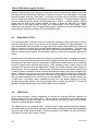
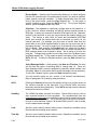
INTRODUCTION.
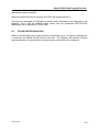
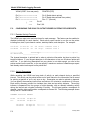
The Eventide VR240 Audio Logging Recorder is an enormous technological advance over the
old-technology reel-to-reel loggers. The VR240 is more efficient and more convenient in almost
every way. It uses less media, less electricity, and less space, yet it provides better quality and
more features than previously possible.
All of these improvements are made possible by the digital technology employed in the VR240.
Instead of recording an analog signal on physically cumbersome tapes, the VR240 converts all
of its inputs to digital form and records them on, among others, “DDS” cassettes or Rewriteable
DVD-RAM. These media will fit in the palm of your hand, yet each can hold up to 800 channelhours of audio or more. The digital format also allows additional information to be stored, such
as time codes and channel content information.
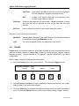
Despite its advanced features, the VR240 Audio Logging Recorder was designed for simple
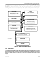
operation. In addition to the vacuum fluorescent display (VFD), there is a set of buttons directly
under the media transport mechanism. These transport control keys emulate the familiar
controls of an ordinary tape recorder. The square buttons under the VFD access a set of
“menus” which control some of the more advanced features of the unit. These buttons are soft
keys whose functions vary as you go through the different menus. One either side of the soft
keys is rectangular keys marked by a left and right arrow. Pressing these keys will either move
you through menu options or, when appropriate, move the cursor around options displayed on
the screen. Finally, there is the keypad that facilitates the entry of parameters and a password.
An LED array on the front panel indicates the status of each channel.
The VR240 is convenient and reliable to use, both for recording and for retrieving recordings
once made. We hope you will enjoy using it.
1-2.
CONFIGURATIONS.
Your VR240 has several features and options that are determined when the unit is ordered. It
may have one or two media drives. It may have 8, 16, or 24 audio input channels. In addition,
the inputs may be configured differently depending upon your audio signal sources. Finally, an
optional label printer provides a provision for automatic media labeling. As you unpack your
VR240, please confirm that the unit you received is the unit you ordered. For your convenience,
the following page is provided to record your unit’s configuration. We suggest that you complete
it now. This information will be required if you should need to communicate with the factory
about your VR240.
January 2000
1-1
Model VR240 Audio Logging Recorder
MODEL VR240, SERIAL NUMBER _______________________ NUMBER OF DRIVES 1
(Serial number and options information appears on the rear panel data plate.)
DRIVE TYPE:
! 4MM DDS ! DVD-RAM ! 8MM EXABYTE
2
! MAGNETO-OPTICAL
FIRMWARE VERSION ______________________________
(On display during turn-on, accessible from the menus.)
If your unit is not configured as desired, or if you should need to change the configuration in the
future, drives and channels can be added easily.
INPUT BOARD #1
INPUT BOARD #2
INPUT BOARD #3
Audio ! or Telephone !
Audio ! or Telephone !
Audio ! or Telephone !
LABEL PRINTER: Y N
1-2
8 Channel (channels 1-8)
8 Channel (channels 9-16)
8 Channel (channels 17-24)
STATUS PRINTER model_________________________________
January 2000
Model VR240 Audio Logging Recorder
Section II. EQUIPMENT DESCRIPTION AND DATA
1-3.
PURPOSE AND FEATURES.
1-3.1 Purpose.
The VR240 Audio Logging Recorder is a multi-channel, full-featured digital logging system. The
recorder archives voice files on DDS-2 or DDS-3 cassettes, or Rewriteable DVD-RAM.
1-3.2 Features.
The VR240 has several features, capabilities, and options.
•
Converts all inputs to digital format and records them on DDS-2 or DDS-3 cassettes,
or Rewriteable DVD-RAM.
•
Media fits in palm of hand, yet each can hold several hundred channel-hours of
audio.
•
Digital format allows additional information to be stored, such as time codes and
channel content information.
•
One or two media drives.
•
May contain 8, 16, or 24 input channels.
•
Input options allow different configurations depending upon the audio signal sources.
•
Transport control keys emulate the familiar controls of an ordinary tape recorder.
•
Easy-to-read VFD (vacuum florescent display).
•
Four soft keys that access displayed functions located directly above them on the
front panel display. These functions vary as you go through the different menus.
The menus control some of the more advanced features of the unit.
•
Contains a front panel keypad to facilitate the entry of parameters and a password.
January 2000
1-3
Model VR240 Audio Logging Recorder
1-4.
EQUIPMENT DATA.
1-4.1 Weight and Dimensions.
33 pounds (14.98 kg)
5 inches (127 mm)
16-7/8 inches (428.6 mm)
17-1/4 inches (438.2 mm) (with 1 inch (25.4 mm) additional extension for
each handle) (rack ears for 19-inch rack mount)
Depth (main frame) 17 inches (431.8 mm)
Weight
Height
Width (main frame)
Width (front panel)
1-4.2 Power Requirement.
The VR240 is factory-configured for the line voltage of the country of installation. Fuse type is
2A, 250V, time-delay, 20 mm (Eventide P/N 316054). Same type is used for 115 Vac or 230
Vac.
1-5.
1-4
ACCESSORIES AND OPTIONS.
Description
Part/Model Number
Label Printer
Status Printer
Accessory Playback Unit
DDS Cleaning Cartridge
PC Remote Control
Satellite Chronometer
DVD-RAM Disk
90 Meter Tape (DDS-1)
120 Meter Tape (DDS-2)
125 Meter Tape (DDS-3)
Magneto-Optical Disk
Desktop Enclosure
Large Internal Hard Drive
Seiko Model SLP1000
Various (serial)
Eventide model VR204 or VP204
Various (Sony recommended)
Eventide Part Number 110000
Eventide Part Number ECW-40
Eventide Part Number 240011
Various (Sony recommended)
Various (Sony recommended)
Various (Sony or Fuji recommended)
Eventide Part Number 240009
Eventide Part Number 240002
Call Eventide to inquire about the
latest size and design
January 2000
Model VR240 Audio Logging Recorder
CHAPTER 2
PREPARATION FOR USE AND INSTALLATION
Section I. FAMILIARIZATION
2-1.
GENERAL.
This section will familiarize you with the VR240. You will learn how to format media, monitor live
communications, begin the record process, enable/disable channels for playback, adjust the
speaker volume, and scroll between the two archive drives and the internal hard disk. It is
recommended that the initial setup be done prior to installing the unit in its permanent operating
location. Chapter 3 of the Operator’s Manual discusses the detailed configuration procedures
for setting up your unit at your facility.
NOTE
It is assumed in this section that you have an audio input signal
available to connect to the Channel One input of the VR240.
2-2.
INITIAL SETUP.
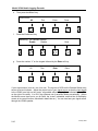
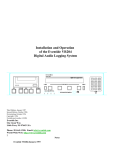
2-2.1 Telephone Board Connection (Phoenix Connector).
Locate an active telephone line in the area you are working.
Connect the telephone line “tip” lead to pin 15 and the “ring” lead to pin 16 of the 16 contact
input connector provided with the unit (note: input is not polarity sensitive). See Figure 2-1.
2-2.2 Audio Board (Amphenol Connector).
Obtain an approximately “line level” signal source. (Something as simple as a “Walkman” or
portable CD player will do.)
Connect the signal source line output to pins 1 and 26 of the top connector on the rear of the
VR240 (using the male 50-pin connector provided). See Figure 2-1.
2-2.3 Additional Hardware.
One blank medium per drive is provided with each VR240. No other hardware is necessary for
this exercise. Monitor the VR240 with its internal speaker. You can also use a set of
headphones (with a mono or stereo phono plug).
January 2000
2-1
Model VR240 Audio Logging Recorder
CH 8
TIP
RING
CH 7
TIP
TIP
RING
CH 5
TIP
RING
CH 4
TIP
CH 3
RING
TIP
CH 2
RING
TIP
CH 1
RING
TIP
Detail A
(16 Pin Phoenix Connector)
Pin 1
Detail A
CH 6
RING
RING
Pin 16
SCSI
SEE MANUAL FOR CONNECTION INSTRUCTION.
ENABLED
UPS
DISABLED
LINE OUT / RELAY
EXT. SPEAKER
12 VDC
PORT A
PORT B
PORT C
PORT D
CAUTION:
TO PREVENT ELECTRIC SHOCK, DO NOT REMOVE
COVER. NO USER SERVICEABLE PARTS INSIDE.
REFER SERVICING TO QUALIFIED TECHNICIAN.
VR240 with three 8-channel telephone boards
pin 25
25
1
Detail B
50
26
pin 50
Complies with Part 68, FCC Rules
FCC Registration Number 4D2USA-21429-RC-N
Ringer Equivalence 0.0 B
!
pin 1
Detail B
pin 26
(See Table 2-1 for pin assignments)
SCSI
SEE MANUAL FOR CONNECTION INSTRUCTION.
ENABLED
UPS
DISABLED
LINE OUT / RELAY
EXT. SPEAKER
12 VDC
PORT A
PORT B
PORT C
PORT D
CAUTION:
TO PREVENT ELECTRIC SHOCK, DO NOT REMOVE
COVER. NO USER SERVICEABLE PARTS INSIDE.
REFER SERVICING TO QUALIFIED TECHNICIAN.
VR240 with one 8-Channel “audio” board
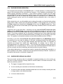
Figure 2-1. VR240 Connections
2-2
January 2000
Model VR240 Audio Logging Recorder
2-3
INITIAL TURN-ON.
NOTE
The VR240 is factory-configured for the line voltage of the country
of installation. Fuse size is 2A, 250V. Refer to paragraph 2-7 for
ensuring correct power.
2-3.1 Power.
The VR240 does not have an ON/OFF switch. To apply power, first plug the power cord into
the rear panel power connector. Next, plug the other end of the cord into a power outlet. The
logger turns on and operates continuously when plugged in.
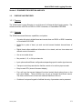
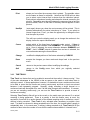
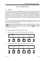
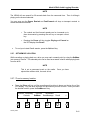
2-3.2 Self Test.
The unit performs a self-test after power is applied. Then the following screen will appear on
the VFD display:
Upper: Not Ready
Controls
SysInfo
Drive
Config
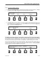
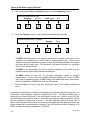
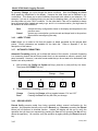
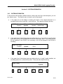
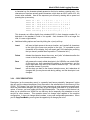
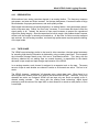
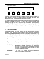
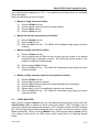
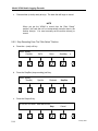
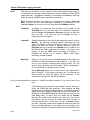
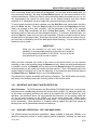
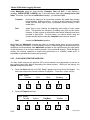
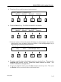
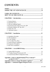
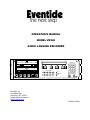
2-3.3 Front Panel Controls.
There are three sets of controls on the VR240 front panel. The transport control keys are
immediately underneath the drive(s). The keypad is on the right of the panel above the
headphone jack. The soft keys are underneath the VFD display. Refer to Section III of this
chapter for a more detailed description of the front panel controls and indicators.
Eventide
DVD
VR240
R A M
Digital Audio
Logging Recorder
DVD
1
2
3
4
5
6
7
8
9
*
0
#
R A M
Channel Status
1
2
3
4
5
6
7
8
9
10
11
12
13
14
15
16
17
18
19
20
21
22
23
24
Full
Rec
Play
Rew
FFwd
Stop
Eject
Almost Full
Phones
Relay
Fault
Figure 2-2. VR240 Front Panel
January 2000
2-3
Model VR240 Audio Logging Recorder
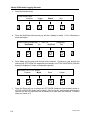
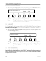
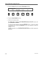
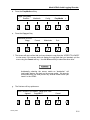
2-3.4 Setting the System Clock.
a.
Press the Config soft key
Upper: Not Ready
Controls
SysInfo
b.
2-4
System
Quit >
Press the SetTime soft key
CLOCK CONFIGURATION
< SetTime
TimeInput
d.
Config
Press the Clock soft key.
Upper: Not Ready
< Clock
Descriptors
c.
Drive
TimeZone
Quit
>
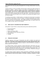
Determine what the time and date will be in about a minute. For example, if it were now
3:27 PM on the 29th of February 2000, the number for 3:28 PM would be “15:28:00 29FEB-00”. Use the Cursor soft key to place the cursor under the parameter(s) you wish to
change. To change the parameter, use either the Decrease and Increase soft keys or
the keypad. When finished, press the Done soft key (you have not yet set the time).
January 2000
Model VR240 Audio Logging Recorder
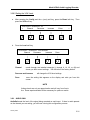
e.
Wait for the second hand to come around to the minute and hit the Set soft key. (Or, if
you made a mistake, hit Cancel and start over.) The clock is now set. If you are running
on Greenwich Mean Time or UTC, you can set the clock to that instead of local time. To
exit this menu without re-setting the time, press the Cancel soft key.
NEW TIME: 15:28:15 29-Feb-00
Set
Cancel
NOTE
The display will give you the time and date as stored in the
VR240. This may be accurate, or completely incorrect if never
set. The VR240 uses 24-hour time and the “European” method of
giving the date as DAY/MONTH/YEAR.
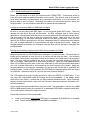
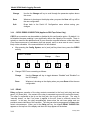
2-3.5 Setting Up Input Channel 1 for Recording.
a.
Press the Config soft key. (NOTE: Config is not available in hard disk menu. Use the
Drive soft key to select either the upper or lower drive.)
UPPER: Not Ready
Controls
SysInfo
b.
Drive
Config
System
Quit
Press the > function key.
CONFIGURATION:
<
Clock
January 2000
Descriptors
>
2-5
Model VR240 Audio Logging Recorder
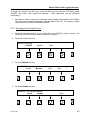
c.
Press the Board soft key
CONFIGURATION:
<
AutoRec
d.
Trigger
Board
Quit
Press the RecEnable soft key and you will see a display for board 1: CH1: followed by a
mode description.
CONFIGURATION BOARD 1: Chan 1-8
(Telephone)
RecEnable
<
Vox
NextBoard
Quit
e.
>
>
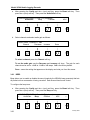
Press Mode soft key and cycle through all the choices. Continue to cycle through the
choices until OFF HOOK (for telephone input boards) or ACTIVE HIGH/OPEN (for audio
boards) is displayed (if it was not displayed originally).
RECORD: CH 01: OFF HOOK
Mode
Channel
Done
Cancel
f.
Press the Done soft key to accept the OFF HOOK (telephone input boards) choice or
ACTIVE HIGH/OPEN (audio input boards). There are many more system configuration
choices, but the only important one at present is to make sure that Channel 1 is active
when you record on it.
2-6
January 2000
Model VR240 Audio Logging Recorder
2-3.6 Media Loading and Formatting.
Before you can record on a drive, the media must be FORMATTED. This process writes an
index and some machine-specific information on the media. The index is used to find specific
times when searching, and also serves as a permanent identification if, for some reason, the
physical label or box is missing. Recording will continue on the internal hard disk during the
format process. You can format on either drive or both drives simultaneously.
Loading and formatting 4MM and 8MM data cartridges;
Be sure to use only data grade DDS tapes. Do not use audio grade (DAT) tapes. These will
damage the tape drive and void all warranties. All DDS cartridges have a “write protect”
mechanism, a small plastic latch that covers a hole on the back of the cartridge (except 8mm).
The latch must cover the hole to allow the media to be written. Make sure this is the case
before continuing. On 8mm data cartridges, make sure the hole is uncovered. Insert your new
tapes in the VR240 by putting them in the slots, transparent side UP, write protect latch towards
you, until a gentle resistance is encountered as the tape is almost fully inserted. Apply just
enough pressure to overcome the resistance, and the drive will pull the tape in and begin the
loading process.
Loading and formatting magneto-optical disks and rewriteable DVD-RAM:
Magneto-optical disks and DVD-RAM come packaged in a protective case. The whole case is
loaded into the machine at once; do not try to remove the disk from the case. You will see a
small plastic “write protect” mechanism located on the bottom left of each side of the protective
case. The latch must be pushed all the way to the right (two red holes showing) to allow the
disk to be written. Make sure this is done before continuing. Insert your new magneto-optical
disks in the VR240 by putting them in the slots, either side up, with the write protect latch toward
you, until a gentle resistance is encountered as the disk is almost fully inserted. Apply just
enough pressure to overcome the resistance, and the drive will pull the disk in and begin the
loading process. Unlike a DDS cartridge, the DVD-RAM and magneto-optical disk can record
on both sides. When one side is full, turn the disk case over and reinsert it.
The VFD display will show the loading process for either the UPPER or LOWER drive. If you
are using new, unformatted media, the display will show Unreadable. (If the display shows
either drive to be Ready, it means that you have inserted formatted media. Since formatting
destroys all data on the media, make sure that it does not have any important information on it
before proceeding.)
All new media must be formatted before they can record. This takes about 4 minutes for a 4MM
DDS or 8MM cassette and a few seconds for a rewriteable DVD-RAM or magneto-optical disk.
You do not need to reformat the media to reuse it.
Follow this procedure to format new media:
a.
Load an unformatted Data Grade DDS tape or rewriteable DVD-RAM into an available
drive. The drive status display will read Media unreadable.
January 2000
2-7
Model VR240 Audio Logging Recorder
b.
Press the > (next) soft key
UPPER: Media unreadable
<
Controls
GoTo
c.
Drive
Config
PrepMedia
Press the Format soft key.
PREPARE UPPER:
Copy
e.
>
Press the PrepMedia soft key.
UPPER: Media unreadable
<
SysInfo
MediaInfo
d.
Resume
MakeIndex
Format
Quit
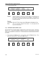
The display will read ‘ERASE ALL DATA ON MEDIA – ARE YOU SURE?” Press the Yes
softkey.
ERASE ALL DATA ON MEDIA
Yes
–
ARE YOU SURE?
Cancel
(Notice that you were given the opportunity to CANCEL this potentially dangerous operation.)
2-8
January 2000
Model VR240 Audio Logging Recorder
To format the media in the other drive, press the Drive soft key until the VFD display reads
“LOWER: Not ready,” then repeat the operation. (Both operations can be performed
concurrently.)
f.
Now that the media in the drive is formatted, notice another characteristic of the VR240.
The menus are sometimes dependent upon the state of the unit. The loading of media
caused new menu choices to become available.
2-3.7 Recording to the Archive Drives.
a.
Once the formatted media is in one or both drives, the VR240 is ready to record. The
first thing to do is confirm that audio is present on channel 1.
b.
Press the Controls soft key.
UPPER: Formatting
Controls
c.
Drive
Press the Monitor soft key.
CONTROLS:
<
Volume
d.
SysInfo
Monitor
Lock
Quit
>
Press the Disable soft key.
Monitoring: All channels disabled
Disable
Enable
January 2000
Done
2-9
Model VR240 Audio Logging Recorder
e.
Then press the All soft key.
CONTROLS:
All
f.
Thru
Enter
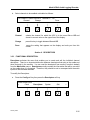
Press the Enable soft key
Monitoring: All channels disabled
Enable
Disable
g.
Done
Done
Press the number “1” on the keypad followed by the Enter soft key.
Enter channel #: 1
All
Thru
Enter
Done
If your signal source is not on, turn it on now. The top row of LEDs on the Channel Status array
serves as a level indicator. Adjust the output level of your signal source so that the input signal
to the VR240 is as high on the “meter” as possible without “clipping”, as indicated by red LEDs
on the right of the array. It is OK if the rightmost set of asterisks flashes occasionally. (When
the Monitor menu times out or you hit Done, the “meter” is disabled, and that line of the display
reverts to its normal function, described in detail later on.) You can now hear your signal source
through the VR240 speaker.
2-10
January 2000
Model VR240 Audio Logging Recorder
2-3.8 Adjust the speaker volume.
a.
Press the Done soft key.
Monitoring: 1
Enable
b.
Done
Press the Volume soft key.
CONTROLS:
Volume
<
c.
Disable
Monitor
Lock
Quit
>
Press the Speaker soft key.
VOLUME:
Speaker
<
January 2000
Headphone
Line
Alarm
>
2-11
Model VR240 Audio Logging Recorder
d.
Press the Lower or Higher key to decrease or increase the speaker volume. The
increments are 0 (no volume) to 40 (maximum volume). To return to the VOLUME:
screen, press the Done soft key.
SPEAKER VOLUME: 15
Lower
e.
To quit this menu, press the > (next) soft key
VOLUME:
<
Speaker
f.
Headphone
Line
Alarm
>
Press the Quit soft key twice.
VOLUME:
<
2-12
Done
Higher
Quit
>
January 2000
Model VR240 Audio Logging Recorder
2-3.9 To put the VR240 in record.
a.
When you see UPPER: Ready, it means that the transport controls are active. To begin
recording, press the Rec transport key located under the archive drives.
UPPER: Ready
<
Controls
b.
GoTo
Drive
Resume
>
The display will ask you to confirm if you wish to record on the selected drive (look to see
that the desired drive is displayed, if not, use the Drive soft key to select the appropriate
drive. Then press the Record soft key.
UPPER: Start Recording?
Record
Cancel
The display now shows (a) that you are recording, and (b) the status of the archive drive(s).
The date and time is also displayed, along with the “media counter,” an electronic equivalent of
the mechanical counter on analog decks. This counter is very important because it may be the
only way you can tell how near the media is to completion. Let the recording run for a while.
Once you start recording, the menu structure changes. Note that when the recording drive is
selected, the display gives you options that make sense while recording. Pressing the Menu
soft key will give you access to additional menu options.
UPPER: Recording 0019 12:27:06
LOWER: Ready
January 2000
29-Feb-00
Menu
2-13
Model VR240 Audio Logging Recorder
It is possible to record on both drives simultaneously. You can do this either by selecting the
non-recording drive with the Drive soft key and repeating the last three steps. Or, if both drives
are loaded and positioned for recording (Ready), press the > (next) function key and then the
DualRec soft key.
NOTE
You have now set up the VR240 so it will be able to do its job. The
rest of the operation’s manual will be slightly less detailed.
Some of the menu choices you have while in the record mode include:
SetMem
(Set memory) Save the location of the message on the medium so you
can go back to that spot later.
SaveMessage
Store a critical communication into one of 16 record buffers.
Instant Recall
Instant Recall is accessed by pressing the Recall soft key. Recalling
during record allows the replaying of a previous passage on any selected channel while the
VR240 continues to record. This is particularly useful when the recording is being monitored in
real time. When Recall is activated and the channel is selected, the available time frame to
listen to is backed up 30 seconds from the current time. From there, selecting Pause, Rewind,
or FastForward enables the operator to quickly locate a selection to listen to. Refer to the detail
procedures in paragraph 5-12.
The following choices can be found by pressing the Controls soft key
Volume
Press the Volume soft key for access to the speaker, headphone, line out and
alarm volume controls.
Monitor
Listen to what is being recorded as it is occurring.
Lock
Used to prevent unauthorized access to all controls except instant recall.
Time Adjust
Allows you to “spring ahead” to daylight savings time. Eventide recommends
that you do not change the clock for daylight savings time. If you set the clock
ahead in the spring you may have trouble in the fall. Setting the clock back
will result in two hour-long sections of media with the same time, making
searching difficult.
2-14
January 2000
Model VR240 Audio Logging Recorder
Section II. INSTALLATION
2-4.
INTRODUCTION.
This section describes the factors that must be considered in setting up the VR240 in your
facility. Consideration of the appropriate physical location must be made for available power
and audio sources. This includes connecting the unit to power, audio, and ancillary items (i.e.,
clock, label printer).
2-5.
PLANNING.
Identify and allocate the inputs to be used as the signal sources for the VR240. Then determine
if you have any channels remaining. If you do, bring them to a convenient patch field as you will
probably find other applications for the VR240 in the future.
Determine the physical location for the VR240. The unit has removable rack mounts and can
be installed in any convenient location that meets the temperature specifications for the unit and
the drives. If you are going to mount it in a rack, do not rely only on the mounts for support – use
a shelf or slide as well. The weight of the unit will exert significant torque on the mounting
hardware. To avoid drive failures and unreliable data transfers the VR240 must be mounted
horizontally not on an angle (such as in some consoles).
Some items to consider:
Convenience
Select a location where changing media can be easily accomplished. If you
do not plan to install remote alarms, locate the VR240 where the media
almost-full, media full, and system fault alarms can be clearly heard.
Security
Do you need to be concerned that someone will want to “destroy the
evidence,” so to speak? If so, how dedicated will that person be? The unit
has security features, but a well-locked door is better!
Power
The Uninterruptable Power Supply will allow the unit to run briefly
(approximately 30 seconds) on batteries while the generator comes up. If you
have a generator, make sure the VR240 will be powered by it. Connect an
inexpensive computer UPS to the logger if outages are frequent or typically
last more than 30 seconds.
Accessibility
Will people continually be using the unit for playback, or will it almost always
be making archival recordings?
Wiring
If almost all the signal sources are in one area, how much wiring do you want
to do to get to the recorder?
Environment
For best reliability, the unit should be placed in a room with comfortable (for
humans) temperature, no extremes of humidity, and as little dust or particulate
matter as possible. A “no smoking” area is preferable.
January 2000
2-15
Model VR240 Audio Logging Recorder
2-6.
SYSTEM CONNECTION.
Figure 2-1 shows the rear panel of the VR240. There can be up to three telephone or audio
input connectors, depending upon the number of optional channel boards installed. Your
primary job will be to connect the input channels to your signal sources. Additional tasks
include providing power, audio output, and, if desired, PC remote control, and printer interface
signals and connections.
2-7.
POWER CONNECTION.
AC Line
This connector provides power to the VR240 using the power cord provided.
The chassis connector is internationally standardized. However, if the VR240
is being used outside the United States, the supplied power cable must be
replaced with a local version.
Line Voltage
The VR240 is factory-configured for the line voltage of the country of
installation. Fuse size is 2 amp, 250V.
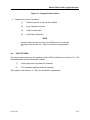
If unsure that the power input setting is correct for the local supply, perform the following:
a.
b.
Remove the top cover as follows:
(1)
Remove fifteen #4 screws.
(2)
Remove five #6 screws.
(3)
Lift and remove the cover slowly and disconnect the speaker.
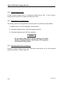
Select the correct voltage selector switch position the on the power supply module (see
Figure 2-3).
Pushing the switch in the UP position is for 115V ac.
Pushing the switch in the DOWN position is for 230V ac.
VOLTAGE SELECTOR SWITCH
115V
2-16
January 2000
Model VR240 Audio Logging Recorder
Figure 2-3. Voltage Selector Switch
c.
Replace the top cover as follows:
(1)
Position top cover on the top of the VR240.
(2)
Plug in speaker connector.
(3)
Install five #6 screws.
(4)
Install fifteen #4 screws.
NOTE
Connect signal sources and mount the VR240 prior to connecting
the power source to the unit. Refer to initial turn-on (paragraph 23).
2-8.
INPUT OPTIONS.
Up to three input boards may be installed in each VR240 mainframe (see Figure 2-2). This
manual describes the two board styles available.
1)
Voice-quality audio input board (8 channels).
2)
FCC-registered telephone board (8 channels).
Other types of input boards (i.e. T1/E1) are described in supplements.
January 2000
2-17
Model VR240 Audio Logging Recorder
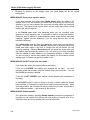
2-8.1 Connecting the Telephone Channel Inputs.
The connector comes with mating plugs. The mating plugs use crimp type screw terminals to
secure the telephone lines (wires). The input impedance is 10kΩ. Looking at the rear of the
unit, each 16-position connector is numbered as follows:
01
02
03
04
05
06
07
08
09
10
11
12
13
14
15
16
Line 8 “tip”
Line 8 “ring”
Line 7 “tip”
Line 7 “ring”
Line 6 “tip”
Line 6 “ring”
Line 5 “tip”
Line 5 “ring”
Line 4 “tip”
Line 4 “ring”
Line 3 “tip”
Line 3 “ring”
Line 2 “tip”
Line 2 “ring”
Line 1 “tip”
Line 1 “ring”
CH 8
TIP
RING
CH 7
TIP
RING
CH 6
TIP
RING
CH 5
TIP
CH 4
RING
Pin 1
TIP
RING
CH 3
TIP
RING
CH 2
TIP
RING
CH 1
TIP
RING
Pin 16
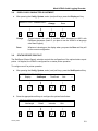
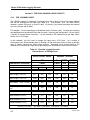
2-8.2 Connecting the Audio Channel Inputs.
There is one 50-position socket on the rear panel of each audio input board. The sockets are
the industry standard telephone type, compatible with the Amphenol 57-series (“blue ribbon”)
connectors. Looking at the rear of the unit, each 50-position socket is numbered as follows:
25 24 23 22 21 20 19 18 17 16 15 14 13 12 11 10 09 08 07 06 05 04 03 02 01
50 49 48 47 46 45 44 43 42 41 40 39 38 37 36 35 34 33 32 31 30 29 28 27 26
pin 25
pin 1
25
1
50
26
pin 50
pin 26
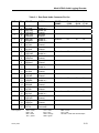
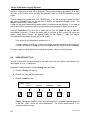
For each of the eight channels on an input board, there are six signals available at the 50position socket: two signals for differential audio input, one for audio output, one for squelch or
record enable control, and two grounds. If there are three input boards installed, the top board
contains channels 1-8, the middle board contains channels 9-16, and the bottom board contains
channels 17-24. Standard 25-pair color-coded cables may be used for system connections
according to the following table 2-1:
2-18
January 2000
Model VR240 Audio Logging Recorder
Table 2-1. Rear Panel Audio Connector Pin-Out
PAIR
PIN
1
2
3
4
5
6
7
8
9
10
11
12
13
14
15
16
17
18
25
26
1
27
2
28
3
29
4
30
5
31
6
32
7
33
8
34
9
35
10
36
11
37
12
38
13
39
14
40
15
41
16
42
17
43
18
50
25
Color Legend:
January 2000
COLOR
SIGNAL
WHT/blu
BLU/wht
WHT/org
ORG/wht
WHT/grn
GRN/wht
WHT/brn
BRN/wht
WHT/slt
SLT/wht
RED/blu
BLU/red
RED/org
ORG/red
RED/grn
GRN/red
Red/brn
BRN/red
RED/slt
Audio in –
Audio in +
Audio out
Ground
Squelch
Ground
Audio in –
Audio in +
Audio out
Ground
Squelch
Ground
Audio in –
Audio in +
Audio out
Ground
Squelch
Ground
Audio in –
Audio in +
Audio out
Ground
Squelch
Ground
Audio in –
Audio in +
Audio out
Ground
Squelch
Ground
Audio in –
Audio in +
Audio out
Ground
Squelch
Ground
(not used)
(not used)
BLK/blu
BLU/blk
BLK/org
ORG/blk
BLK/grn
GRN/blk
BLK/brn
BRN/blk
BLK/slt
SLT/blk
YEL/blu
BLU/yel
YEL/org
ORG/yel
YEL/grn
GRN/yel
VLT/slt
SLT/vlt
WHT = white
RED = red
BLK = black
YEL = yellow
VLT = violet
BLU = blue
ORG = orange
GRN = green
BOARD:
CHANS
Channel
Top
01-08
01
Mid
09-16
09
Bot
17-24
17
Channel
02
10
18
Channel
03
11
19
Channel
04
12
20
Channel
05
13
21
Channel
06
14
22
BRN = brown
SLT = slate
WHT/blu = white wire with blue stripe
2-19
Model VR240 Audio Logging Recorder
2-8.3 Squelch Requirements.
A “high” is either an open circuit, or a voltage level greater than 4 volts. A “low” is either a
contact closure to ground or a voltage level lower than 2 volts.
2-8.4 Audio Board Front-End Options.
The following options are configurable from the front panel on a channel-by-channel basis:
1) Balanced input, >10K ohm impedance, transformerless
2) Transformer balanced input, >10K ohm impedance @ 1kHz
3) Transformer balanced input, 600 ohm impedance
Do not connect Audio Board channels directly to the Public
Switched Telephone Network. Use Eventide’s FCC-registered
input boards for this purpose.
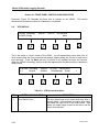
2-8.5 Rear Panel Serial Port Connectors.
Connect the desired ancillary items (clock, label printer, status printer, etc.) to the rear panel
serial port connectors. Refer to Figure 2-5.
2-20
January 2000
6
Serial Chan. 2: RS-232 data channel # 2
2
Serial Chan. 1: RS-232 data channel # 1
7
1
Model VR240 Audio Logging Recorder
9
6
Serial Chan. B: RS-232
Serial Chan. H: RS-232 (reserved)
2
1
5
Serial Chan. F: RS-485 for time code input, remote record control
7
4
8
3
Ground
9
6
Label printer handshake, +12V
Serial Chan. B: RS-232 time code input
Serial Chan. D: RS-232 label printer
2
1
5
Serial Chan. E: "PC Remote", RS-485 party line
7
4
8
3
Ground
9
6
Serial Chan. A: time code output
Serial Chan. C: RS-232 status printer
2
1
5
Serial Chan. F: RS-485 for time code input, remote record control
7
4
8
3
Ground
Serial Chan. E: "PC Remote" connection, RS-485 party line
5
9
4
8
3
Ground
Figure 2-5. VR240 CPU: Rear Panel Serial Port Connectors
January 2000
2-21
Model VR240 Audio Logging Recorder
Section III. FRONT PANEL CONTROLS AND INDICATORS
Previously, Figure 2-2 illustrated the three sets of controls on the VR240.
describes the front panel controls and indicators in more detail.
2-9.
This section
VFD DISPLAY
UPPER: Recording
LOWER: Ready
000019
12:33:01
29-Feb-2000
Menu
This is the status or “Home” screen of the VR240. You will automatically return here from all
other screens after the time-out period has passed (approximately one minute for each menu
level selected). Press the Menu soft key for access to all available functions and controls.
When the VR240 is recording, the first screen that appears after the Menu soft key is pressed is
shown below:
① UPPER: Recording
②<
Controls
000019
SetMem
12:33:01 29-Feb-2000
SaveMessage Recall
>
Table 2-2. VFD Screen Description
ITEM
1
2-22
CONTROL OR INDICATOR
Drive Status Lines
DESCRIPTION
The drive status lines let you know what each drive is
currently doing. In this example, the upper drive status
line shows the upper drive in the record mode. Also
shown is a media usage counter for that drive, and the
current time and date.
January 2000
Model VR240 Audio Logging Recorder
ITEM
2
CONTROL OR INDICATOR
Soft Keys
DESCRIPTION
A maximum of four functions is displayed on this line.
Each function corresponds to a soft key located directly
under the display. From this screen, pressing the soft
key labeled “Controls” will give you access to the
submenu containing “Monitor,” “Volume,” and “Lock”
screens.
In some instances, more functions are available than
can be shown at one time. When this is the case, the
< (previous) and > (next) function key will be displayed.
Press either soft key to step through additional menu
selections.
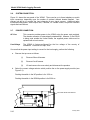
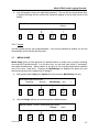
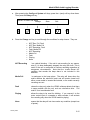
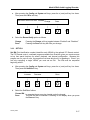
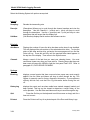
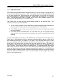
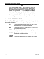
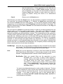
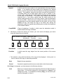
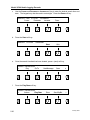
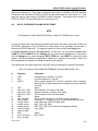
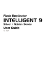
2-10. DRIVES.
Table 2-3 describes the Drive Controls and Indicators.
1
6
5
Channel Status
1
2
3
4
5
6
7
8
9
10
11
12
13
14
15
16
17
18
19
20
21
22
23
24
Full
Rec
Play
Rew
FFwd
Stop
2
Eject
Almost Full
Fault
3
4
Table 2-3. Drive Controls and Indicators
ITEM
CONTROL OR INDICATOR
DESCRIPTION
1
Archive Drives
These may be 4MM DDS tape, rewriteable DVD-RAM,
8MM Exabyte cassette, or magneto-optical disk. The
VR240 logger may be equipped with a single drive or,
more commonly, with dual drives.
2
Transport Controls
You may use these controls to operate both the drives
and the internal hard disk. Pressing the Rewind and
FFwd (fast forward) transport keys multiple times can
increase the speed of the rewind and fast forward
functions.
January 2000
2-23
Model VR240 Audio Logging Recorder
ITEM
3
CONTROL OR INDICATOR
Full
DESCRIPTION
Indicates that one of the archive drive media has been
recorded on to capacity.
Almost Full
A yellow light indicates that the media in that drive has
one half hour or less of record time available.
4
Fault
A yellow light indicates that an archive drive or internal
hard disk failure may have occurred. It may also indicate
that the “cleaning timers” must be reset.
5
Media Drive Indicator Lights
Different tape and disk drives have their own indicator
lights. In most cases, ignore these lights. In general, the
VR240 display provides more and better information.
6
Channel Status Array
These LEDs will light as required to report the current
state of each installed channel. They will light under the
following conditions:
Red – indicates that the channel is currently being
recorded
Yellow – indicates the channel is currently being
monitored.
Green – indicates 1. that channel is configured to record
when signal is present but 2. there is currently no signal
present.
No light – indicates that the channel has been disabled
so that it will not record. A yellow light indicates that an
archive drive or internal hard disk failure may have
occurred. It may also indicate that the “cleaning timers”
must be reset.
2-24
January 2000
Model VR240 Audio Logging Recorder
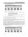
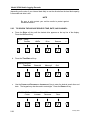
2-11. KEYPAD AND FRONT PANEL PORTS,
Table 2-5 describes the front panel controls and ports.
Table 2-5. Front Panel Controls and Ports Description
ITEM
CONTROL OR INDICATOR
DESCRIPTION
1
Numeric Keypad
The keypad can be used in place of the soft keys when
entering numbers in the VR240. This will prove
convenient when entering a time and date for a search
or selecting a channel to monitor or play. The keypad
is also used to enter a password.
2
* (asterisk)
Pressing the asterisk button during “auto-record” will
cancel the timed recording.
To set the unit back to the factory defaults, press this
key while the unit powers-up.
3
# (pound symbol)
In many instances, the # pound symbol may be used
interchangeably with the Enter soft key.
4
Relay
The relay jack can be used to trigger a remote alarm.
It can also be configured in conjunction with the line
out jack for use with a stop/start, hand-held or other
external cassette recorder.
5
Phones
Headphone jack for ¼” phone plug equipped headsets.
The volume of this output is controlled by a soft key
located in the Controls menu.
January 2000
2-25
Model VR240 Audio Logging Recorder
CHAPTER 3
SOFTWARE CONFIGURATION
Section I. SETUP
3-1.
DESCRIPTION.
Setup is a configuration procedure performed from the front panel of the VR240. At this point,
we assume that the unit is connected to power and audio, and is powered up. If so, you will be
looking at a display with a legend indicating either Ready or Not Ready depending upon
whether the drive is loaded. A “soft key” is the button immediately below the legend in bold.
Saying “press the System soft key” means that there is a legend “System” on the display and
you must press the key immediately below it.
3-2.
MENU OPERATION AND TIMEOUT.
To facilitate operation of the VR240, we have made some assumptions that cause the soft key
menus to change depending upon circumstances. For example, the menu options while playing
will be different than when the unit is in the record mode.
Another important aspect of menu operations is “time-out.” You are given a period of time to
perform operations under the menus you select. Menus have levels. Refer to Appendix I. In
computer terminology, the Home screen display is the “root.” GoTo is one selection on the next
level, or one of the “branches.” Menus can have multiple levels, but you will eventually reach
the last level (“leaf”) and will either perform or not perform the action on that level. In order to
prevent the unit from continuously displaying an action, perhaps one you don’t want to perform,
each menu times out to the next level, until eventually the root is reached. That way, the unit
will eventually return to a known state, and if another user comes upon it, they won’t have to
backtrack your operations to get it to do what they want.
The balance of this section describes in detail the steps performed under the Config menus.
As shipped from the factory, each of the configuration items is set to a logical “default.” If the
default is unsatisfactory, change it as needed.
NOTE
The unit cannot be configured when in record. Be sure you are
not recording to the internal hard disk or either archive drive.
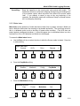
3-3.
SETTING THE CLOCK.
It is very important that the system clock be set to any legal date between 1 January 1989 and
31 December 2088. The clock can be set to local time or UTC, previously known as Greenwich
Mean Time.
January 2000
3-1
Model VR240 Audio Logging Recorder
When setting the system clock, the display will give you the time and date as stored in the
VR240. This may be very close to accurate, or completely incorrect if never set. The clock is
powered by a lithium battery that allows it to keep time even if no power is applied to the VR240.
If the battery is discharged, the date and time will be wrong. This will affect the playback
functions when time and date is selected. With only the last two digits of the year displayed, the
wrong clock setting may affect the re-recording of older media you may want to archive.
Refer to paragraph 2-3.4 for setting the system clock.
3-2
January 2000
Model VR240 Audio Logging Recorder
Section II. GLOBAL SYSTEM CONFIGURATION
3-4.
SYSTEM.
System configuration sets the various options that define recorder operation apart from the
clock and the individual channels as described in section 1 and Chapter 2. Pressing the
Config soft key accesses the System configuration menu.
The top line of the display must read either “UPPER” or “LOWER.” If “DISK” appears on this
line, press the Drive soft key to select an archive drive. The Config soft key is available from
the first menu screen when there is no media loaded in the archive drives. If you have
formatted media in an archive drive, press the > (next) soft key for access to Config. Again, this
function is not available when the VR240 is recording. To view the Config screen:
a.
Press the Config soft key.
Upper: Not Ready
Controls
SysInfo
b.
Drive
Config
Press the System soft key.
CONFIGURATION:
<
Clock
Descriptors
System
Quit
>
You have now reached the System Configuration menus.
3-5.
SAMPLING.
Sampling allows you to select the sampling rate of the recorder. The VR240 uses digital signal
processing to compress the input audio. As discussed elsewhere in this manual, the number of
samples determines the media usage. This is a linear function. Doubling the sampling rate
reduces the recording time by half. The audio quality of the VR240 is dependent on the
sampling rate.
January 2000
3-3
Model VR240 Audio Logging Recorder
a.
After pressing the Config and System soft keys, press the Sampling soft key.
SYSTEM CONFIGURATION:
Sampling
<
Security
b.
MediaUsage
Quit
>
Press the Change soft key to cycle through the available sampling rates.
TRANSCODING RATE: 32 kbps
Change
Done
16 KBPS (kilobits/second) is the slowest sampling rate available, and gives the full
recording time available from a DDS media or magneto-optical disk. Normal voice
signals are perfectly intelligible at this rate, but the signal sounds somewhat more harsh
and noisy than the faster rates. This should be used when the media is to be played
back only for human listeners.
32 KBPS is an intermediate rate that is generally satisfactory for recording all but
facsimile and the highest speed modem transmissions.
64 KBPS should be used only for recording high-speed modem or facsimile
transmissions. There is little or no audible difference between the 32 and 64 KBPS
rates, and for broadcast logging, 64 KBPS simply uses media faster with no real benefit.
64K is not available in VR240s with more than 16 channels.
c.
Press the Done soft key to save your setting and return to the system configuration
menu.
A technical note: Normally one would expect sampling rate to change frequency response. The
VR240 has a fixed frequency response of slightly over 3 kHz. This would normally imply a
sampling rate of about 8kHz and, in an 8-bit system like this one, a 64K (8 times 8) bit per
second sampling rate would be required. Since that is the highest sampling rate used, you can
see that something is being done to lower it. The DSP algorithms used at 32K and 16K, in
effect, discard redundant information, and enable the full bandwidth to be reproduced with fewer
bits per sample than would otherwise be required. The DSP algorithm is almost “lossless” at 32
KBPS, but does cause some degradation at 16 KBPS.
3-4
January 2000
Model VR240 Audio Logging Recorder
3-6.
SECURITY.
The VR240 has a security feature that is intended to prevent operation and, if desired, media
removal, by unauthorized personnel. In several operational menus, you have the opportunity to
Lock the unit by entering an 8-digit password. Once you have done this, the front panel
controls will be unresponsive until the password is re-entered.
It also is possible to LOCK the unit in various states. From the CONFIG/SYTEM/SECURITY
menu, you can LOCK the VR240 in an inoperative state to prevent its being used at all.
CONFIG/SYSTEM/SECURITY is also the menu that allows you to change the password.
3-6.1 Select Security Levels.
There are two security levels with access options available at each.
a.
After pressing the Config, System, then Security soft keys press the Security Level
soft key.
SECURITY:
Changpaswd
b.
Lock
Security Level
Quit
Use the Change soft key to scroll through the two options. When finished, press the
Done soft key. Whatever is showing on the display when you press Done will be the
current setting.
SECURITY LEVEL: High Security
Change
Done
High Security Whether or not the VR240 is in a “locked” state, this level of security
denies access to the Config menu. This will prevent accidental or unauthorized changes
that would affect operation of the VR240. High security also password protects the
TIME ADJUST and MEDIA USAGE menus during record.
Low Security When the VR240 is “locked” and in “Low Security” mode, you must use a
password to unlock the unit. Once the unit is unlocked, access to all menus is available.
January 2000
3-5
Model VR240 Audio Logging Recorder
3-6.2 Change user password.
When the VR240 is shipped, it is initialized with an 8-digit password “00000000” (eight zeros).
This will be the password unless you change it from this menu. When you press the the
ChangPaswd soft key, the unit requests the original password, which you enter using the
keypad. Once you enter the correct password, it will ask you for a new (8-digit) password. You
are requested to enter the password twice, to prevent errors. If you enter the password twice
and both versions are identical, the VR240 will accept the new password and the old one will
then be invalid. If you do not enter the correct “old” password or if you make any mistakes
during this procedure, it will abort and leave the password unchanged.
a.
After pressing the Config, System, then Security soft keys press ChangPaswd
SECURITY:
ChangPaswd
Lock
Security Level
Quit
IMPORTANT !
If you do plan to use the security features of this unit, we strongly recommend
that you change the password. As you can see, the initial password is printed in
this manual and is also available by calling Eventide Technical Support. If you
do change the password, DON’T FORGET IT! We have no way of knowing what
your password is, and cannot help you if you lose it.
3-6.3 Lock
This key will lock the unit (once you have correctly entered the password as requested). If you
lock the unit while in this menu - and you have set your security level to “low” - you will have no
access to the controls until you unlock it.
a.
After pressing the Config, System, then Security soft keys press the Lock soft key.
SECURITY:
Changpaswd
3-6
Lock
Security Level
Quit
January 2000
Model VR240 Audio Logging Recorder
b.
Use the keypad to enter your eight-digit password. The unit will now automatically lock.
A legend indicating that the controls are locked will appear in the top right corner of the
display.
Enter Password:
Cancel
3-6.4 Unlock
Use the keypad to enter your 8-digit password. If the correct password is entered, the unit will
automatically unlock with the last key press.
3-7.
MEDIA USAGE.
Media Usage gives you the opportunity to decide whether to record over or prevent recording
over previously recorded media. In a two-drive unit, you can load (and format, if necessary),
two media simultaneously. When medium in one drive is full, recording automatically switches
over to the other, ready drive. Pressing the MediaUsage key displays the option you have
selected and gives you the opportunity to change it.
a.
After pressing the Config then System soft keys press the MediaUsage soft key.
SYSTEM CONFIGURATION:
<
Sampling
Security
b.
MediaUsage
Quit
>
Use the Change soft key to scroll through the available options.
MEDIA USAGE: Do NOT record over prev media
Change
January 2000
Done
3-7
Model VR240 Audio Logging Recorder
c.
Whatever is showing on the display when you press Done will be the current
configuration.
MEDIA USAGE: Record over previous media –
If you have selected this option under Media Usage, when the media in the
second drive is full, the recorder will switch back to recording on the first one,
whether or not you have removed the previously recorded media and inserted a
fresh one. This option should only be used if you are certain that nothing on that
medium will ever be required.
In the Record over mode, and especially when you are recording many
channels at a high sampling rate, it is possible to overuse a particular medium.
Please be sure to adhere to recommendations about media lifetime and head
cleaning. (Ignore this last statement if you are using disks as they can be
rewritten indefinitely.)
On a single drive recorder, there is no automatic switch-over from one drive to
another. On these units, selecting Do NOT requires you to physically remove the
media and either insert a new one or reinsert the old one before you can
continue recording. Selecting Record over will not restart the single drive once
the medium has automatically rewound, but it will allow you to begin recording
when the medium is ready, whether or not it has been changed. In other words,
you do not have to remove and reinsert the medium (or new medium) before
starting again if “Record over previous media” is set.
MEDIA USAGE: Do NOT record over prev media –
If you select this option, the system behaves as follows:
If the unit is LOCKED, the medium just recorded will not eject. You must
manually unlock the recorder, eject the medium, and insert a new one. You can
then LOCK the recorder if desired.
If the unit is NOT LOCKED, each medium will be ejected upon completion of
recording.
In the Do NOT mode, in order to record on a drive on which media has already
been recorded, it is necessary to eject the old medium and insert another. When
you insert medium, the unit does not check to make sure it is new, unrecorded or
even a different medium. It just checks for the ejection.
MEDIA USAGE: Disable transfer –
On a dual-drive recorder, selecting Disable transfer prevents the completion of
recording on one medium from starting the other medium in record, even if it is
otherwise ready and can be started with a manual command.
3-8
January 2000
Model VR240 Audio Logging Recorder
3-8.
a.
DISPLAY ASCII CHARACTER ADJUSTMENT.
After pressing the Config, System, and > (next) soft keys, press the Display soft key.
DISPLAY TYPE: Standard ASCII
Change
3-9.
Done
Change
Toggle between the option of standard ASCII characters or ASCII with
European characters (useful if you plan to use the VR240 in a language
other than English).
Done
Whatever is showing on the display when you press the Done soft key will
be the current configuration.
STATUS REPORT PRINT OUT.
The StatReport (Status Report) selection controls the configuration of the optional status report
printer. As shipped, the VR240 is configured for no status printer operation.
To configure a unit for printer operation:
a.
After pressing the Config, System, and > (next) soft keys, press the StatReport soft key.
SYSTEM CONFIGURATION:
StatReport
<
Display
b.
TimeTrack
Quit
>
Press the appropriate soft keys to configure the options listed below:
STATUS REPORT CONFIGURATION:
LineLength
Detail
Intervals
January 2000
Quit
3-9
Model VR240 Audio Logging Recorder
The following menus are used to configure the status printer. If you have not connected a
status printer, these settings should be left at their default values (Line Length: 78; Detailed
Activity Report: CHAN 01: off, Intervals – Summary: None, PRINT: None, NEXT RPT: 00:00).
LineLength allows you to limit the length of each printed output line to correspond to the
physical characteristics of your printer. The default is 78 characters per line, which is 2 fewer
than the length of most letter size (8-1/2 x 11) printers. (Some printers may count carriage
return or line feed characters as part of a line and skip a line if you set your line length to 80
characters.)
Decrease
reduces the length to a minimum of 78 characters by pressing or holding
the button. (The setting “wraps around” to 132 if you try to reduce the
length below 78.)
Increase
permits a line length of up to 132 characters to be selected by pressing or
holding the button. (The setting “wraps around” to 78 if you try to exceed
132.)
Done
accepts the new length and drops back to the printer configuration menu.
Cancel
drops back to the printer configuration menu without changing the length.
Detail allows you to configure the printer to show individual “messages.” A new line is printed
whenever a channel is activated automatically (by signal being present) or by the transition of its
squelch input, either from off to on, or from on to off.
Channel
selects the channel for which you wish to activate or deactivate the
message reporting capability. Pressing this button scrolls through all 24
channels and shows their current status on the display. Press the
Channel soft key to cycle through the channels displayed.
Change
cycles the current status from Off to On to Off. Press the Change soft
key to switch each Channel to On or Off.
Done
accepts any changes you have made and drops back to the previous
menu. Press the Done soft key after selecting the desired channel status
(to be included or excluded in the status report printout).
Cancel
drops back to the previous menu without changing the configuration.
Intervals allows you to select how often channel utilization is summarized, and how often the
summaries are printed. It also gives you an opportunity to select the time of day of the
summary printout. When you hit the Intervals soft key, the display shows the current setup as
follows:
Summary
3-10
shows you how often the summary data is collected. Possible values are
None, 5, 10, 15, 20, and 30 minutes, and 1, 2, 3, 4, 6, 8, 12, and 24
hours. Each summary consists of a single line showing the activity
during the summary interval.
January 2000
Model VR240 Audio Logging Recorder
Print
shows you how often the summary data is printed. The possible values
are the same as those for collection. Note that the VR240 will not allow
you to select a print interval that is shorter than the collection interval.
Each printout comprises a heading and shows the interval covered by the
printout. Depending upon the ratio between the summary interval and the
printout interval, from 1 to 288 lines of summary data will appear on each
printout.
NextRpt
(next report) shows you when the next summary will be printed. This is
selected automatically for printer intervals up to 1 hour. If you select an
interval longer than 1 hour, you have the opportunity to change the time
that the report is printed.
The soft keys under the display permit you to change the numbers in the
display, hence the report characteristics.
Cursor
selects which of the three items is presently under control. If None is
selected, the cursor remains under SUMMARY. If a summary interval of
up to 1 hour is selected, the cursor alternates between SUMMARY and
PRINT. And if a PRINT interval of greater than an hour is selected, the
cursor alternates among the three choices.
Change
modifies the displayed time of the feature selected by CURSOR.
Done
accepts the changes you have made and drops back to the previous
menu.
Cancel
returns to the previous menu without modifying the settings.
Quit
returns to the Config menu from which you originally selected
StatReport.
3-10. TIME TRACK.
Time Track is a feature that can be enabled to assure that the media is “always running.” One
of the main advantages to the VR240 is that no space on the media is used when there is
nothing to record. In some applications, however, it is desirable to have a continuous time track
to be able to prove that the media was running continuously and that no input was missed
because it was temporarily stopped. Normally, simply recording a single channel on a
continuous basis will accomplish this, even if all the other channels are intermittent. If, however,
you are not recording continuously, you can turn the Time Track on to provide a record of
continuous recording.
Selecting Time Track to On will put a time mark on the media once per second if no actual
recording is being performed. There is a penalty in that this feature uses, at most, the
equivalent of one-half of an audio channel (at the slowest sampling rate) of media time, even if
nothing is being recorded. Time Track is only activated when necessary to provide a time
mark. If at least one channel is being recorded most of the time, the “wasted media” penalty is
substantially less. In the worst case, if nothing is being recorded at all, Time Track will fill the
medium in about twice the number of hours that the medium has available in “channel hours.”
January 2000
3-11
Model VR240 Audio Logging Recorder
To turn on or off the Time Track feature:
a.
After pressing the Config, System, and > (next) soft keys, press the TimeTrack soft key.
RECORD TIME TRACK: Off
Change
Done
Change
Cycles the feature from Off to On and back.
Done
Exits the Time Track menu. Whatever is showing on the display when you
press Done will be the current configuration.
3-11. LANGUAGE.
As of this printing, the only language available in the VR240 is English. From time to time you
may want to check our web site or the local trade magazines for news of the availability of
French and German languages.
a.
After pressing the Config and System soft keys, press the > (next) soft key twice. Then
press the Language soft key.
LANGUAGE: English
Change
Done
Change
When alternate languages are available, this key will scroll through them.
Done
Exits the Language menu. Whatever is showing on the display when you
press Done will be the current configuration.
3-12. COPY CONFIGURATION.
Copy Configuration (CopyConfig) sets the VR208HF system-configuration parameters to
match those found on the media in the archive drive. Best results are achieved when the
archive media was recorded on a logger with the same software version and hardware
configuration as the VR208HF.
3-12
January 2000
Model VR240 Audio Logging Recorder
NOTE
Some parameters will not be copied from the archive media.
These are: Unit serial number, PC-Remote ID number, SCSItype
and SCSIterm settings.
a.
After pressing the Config and System soft keys, press the > (next) soft key twice. Then
press the CopyConfig soft key.
Overwrite UNIT CONFIG with MEDIA CONFIG
Continue
Cancel
Press the Continue soft key and the unit will automatically update its parameters with those on
the archive media.
3-13. SERIAL I/O PORT PARAMETERS.
Serial I/O brings up a selection of data communication parameters for the RS-232 and RS-485
ports on the back of the unit. These ports are used to connect to printers (including the optional
label printer), PC remote control, master clock systems, and other external control devices.
The VR240 supports two types of printers, an optional label printer, and an optional status
printer. The label printer automatically prints a label that identifies media when it is ejected.
The status printer lists and can depict graphically, activity on the individual channels. Separate
appendices discuss each of these printer options.
Adjust the Serial I/O parameters as follows:
a.
After pressing the Config, System, and > (next) soft key twice, press the SerialI/O soft
key.
CHAN A: 19.2
Cursor
b.
BITS:8
Change
STOP:2
Save
PARITY:NONE
Quit
Choose parameters as follows:
Cursor
January 2000
Use the vertical or side-to-side arrow keys to move the cursor through the
Channel number, Bits, Stop, and Parity parameters
3-13
Model VR240 Audio Logging Recorder
Change
Use the the Change soft key to scroll through the parameter options above
the cursor.
Save
Whatever is showing on the display when you press the Save soft key will be
the new configuration.
Quit
Drops back to the Serial I/O Configuration menu without saving your
changes.
3-14. C3ECC ERROR CORRECTION (Applies to DDS Tape Drives Only).
C3ECC error correction can be enabled or disabled by this configuration option. By default, it is
left disabled, because enabling it can significantly reduce the capacity of the media. There is
typically no need for this additional level of error correction on audio because, unlike data, there
is an enormous amount of redundancy built into speech, and if an error were to occur, it would
likely not be noticeable. We recommend that it be left disabled.
a.
After pressing the Config, System, and > (next) soft key three times, press the C3ECC
soft key.
C3ECC: Enabled
Change
b.
Done
Change C3ECC error correcting as follows:
Change
Use the Change soft key to toggle between “Enabled” and “Disabled” on
the VFD display.
Done
Whatever is showing on the display when you press Done will be the new
configuration.
3-15. RELAY.
Relay configures operation of the relay contacts connected to the front (mini-plug) and rear
panel (1/4” phone jack). One contact of the relay is connected to ground (the connector sleeve).
The other is connected to the tip on the front jack, the ring on the rear jack. The relay is
“normally closed”, so that if no power is applied to the unit, there is continuity across the
contacts. In this way, the relay unconditionally closes when the unit loses power and can
provide a remote indication of this condition. The relay can also be programmed to Close under
certain circumstances. When you hit the Relay soft key, the legend RELAY CLOSES ON:
appears on the top line of the display and three soft keys appear on the bottom.
3-14
January 2000
Model VR240 Audio Logging Recorder
a.
After pressing the Config and System soft keys, press the > (next) soft key three times.
Then press the Relay soft key.
RELAY CLOSES ON: None
Change
b.
Save
Quit
Press the Change soft key to scroll through the conditions for relay closure. They are:
•
•
•
•
•
•
•
•
•
NOT Rec, Full, Fault
NOT Rec, Media Full
NOT Recording, Fault
Fault, Media Full
NOT Recording
Media Full
Fault
Playing
None
NOT Recording
is a catchall situation. If the unit is not recording for any reason,
even if it is been deliberately stopped, the relay will close. This is
useful if the unit is configured to continue recording regardless of
exogenous circumstances. Note that the “media almost full”
condition that sounds the beep alarm is not included in this
definition.
Media Full
is analogous to the beep alarm. The relay will close when the
media reaches the almost-full point and will remain closed until
either a new media is inserted and started, or the media currently
recording runs out.
Fault
closes the relay only when the VR240 software detects that there
is some problem with the unit, such as a defective drive. “Full
media” is not considered a fault.
Playing
allows the relay to be used for dubbing. If you connect it to the
motor control input of a cassette or other recorder, it will activate
the recording only when the VR240 media is playing.
None
means that the relay will not close under any condition (except loss
of power).
January 2000
3-15
Model VR240 Audio Logging Recorder
By pressing Change, you cycle through the above conditions. Note that Playing and None
each appear by themselves on the display. However the other three can be selected in any
combination. This allows you to select conditions that need to be called to your attention. For
example, if you are in a location where you can hear the beeping alarm, you may wish to have
the relay close only on a FAULT condition. On the other hand, if the unit is expected to always
have the second drive loaded and ready to go, and it is in a remote location, you might want to
be alerted to all three conditions.
Accepts the relay configuration shown in the display and drops back to the
previous menu.
Cancel
Ignores any new selection you have made and drops back to the previous
menu without reconfiguring the relay.
3-16. LABEL TITLING.
Save
Label allows you to select a title that will appear on labels generated by the optional label
printer. Eleven characters are available for the label title. Refer to Appendix F for the
description of this feature.
3-17. AUTOMATIC FORMATTING.
Automatic Formatting permits you to defeat this feature of the recorder. Automatic formatting
is a timesaving feature that will format media that is to be recorded on without a specific front
panel command. However, it can also format media that you do not want to be formatted if that
media is not write protected.
a.
After pressing the Config and System soft keys, press the > (next) soft key four times.
Then press the FORMAT soft key.
AUTOMATIC FORMATTING:
On
Change
b.
Done
Select Automatic Formatting option as follows:
Change
Done
Pressing the Change soft key toggles between “On” and “Off.”
Pressing the Done soft key will save your change.
3-18. RECORD VERIFY.
Record Verify prevents media from being recorded without manual confirmation by the
operator. Any operation that will put the unit in Record (e.g., Resume or pressing the Record
button) will not perform its intended function. Instead, the display will ask you to verify the
operation that you have just requested by pressing the Yes soft key (pressing the No soft key
aborts the operation). You can also verify the operation by again pressing the Record transport
key.
3-16
January 2000
Model VR240 Audio Logging Recorder
a.
After pressing the Config and System soft keys, press the > (next) soft key four times.
Then press the C3Ecc soft key.
RECORD VERIFICATION: Enabled
Change
b.
Done
Select the Record Verify option as follows:
Change
Done
Pressing the Change soft key toggles between “Enabled” and “Disabled.”
Pressing the Done soft key will save your change.
3-19. SET ID #.
Set ID# (Set identification number) identifies each VR240 to the optional PC Remote control.
The PC Remote control, a software program available from Eventide, gives you remote access
to key front panel functions for search, playback, and channel configuration. Because this
program can run up to 8 units, the program must know which unit it is speaking to. Even if you
are only controlling a single VR240, you must set an ID#. The ID# must be sequential
beginning with 01.
a.
After pressing the Config and System soft keys, press the > (next) soft key four times.
Then press the SetID# soft key.
Network ID # : 01
Increase
b.
Decrease
Done
Select the SetID# as follows:
Choose ID#
Done
January 2000
by pressing the up arrow key located under the keypad.
The new ID# will be whatever is showing on the display when you press
the Done soft key.
3-17
Model VR240 Audio Logging Recorder
3-20. DISK CONTROL.
This setting has meaning only if your VR240 has two removable archive drives. “DiskContrl”
offers you a choice between two modes of operation. The two choices are:
•
•
Separate Hard Disk Control for each Drv (Separate Mode)
Automatic Disk Control (Public Safety) (Automatic Mode)
To understand the difference between Separate mode and Automatic mode, you need to know
something about how the VR240’s internal hard disk is used.
Whenever you start recording on the Upper archive drive, the VR240 creates a file on the hard
disk. The file name will be something like UPRFILE. Audio from the input boards is
accumulated in UPRFILE. When UPRFILE grows to a certain size, most of the data in it is
transferred to the upper media drive, and the size of UPRFILE is decreased. If the media in the
upper drive becomes full and the lower drive is not ready to record, audio will continue to
accumulate in UPRFILE.
If you press Stop and select Suspend, the VR240 will stop transferring material to the upper
drive but it will continue to accumulate material in UPRFILE.
The following table describes what happens when you load media in either drive and press
Record.
ACTION
The VR240 is
recording with no
medium loaded in
either drive.
Medium is loaded in
the upper drive and
RECORD is pressed.
Medium is loaded in
the lower drive and
RECORD is pressed.
VR240 RESPONSE IN
AUTOMATIC MODE
Audio is being recorded and
saved to UPRFILE on the
hard drive.
VR240 RESPONSE IN
SEPARATE MODE
Audio is being recorded and
saved to UPRFILE on the
hard drive.
Contents of UPRFILE is
transferred to the medium in
the upper drive.
Contents of UPRFILE is
transferred to the medium in
the upper drive.
UPRFILE is renamed
LWRFILE. All accumulated
material is transferred to the
medium in the lower drive.
A new file called LWRFILE is
created and used to
accumulate and transfer
material to the medium in the
lower drive.
This means that under certain
conditions with the VR240 in
the Automatic mode, you do
not need to remember which
media drive the VR240 has
been set up for saving
material.
3-18
REMARKS
No difference
between Automatic
and Separate
Modes.
No difference
between Automatic
and Separate
Modes.
Separate Hard Disk
Control is
recommended.
The VR240 tells you for each
drive whether or not material
is being saved for that drive.
The screen display will show
“Ready (disk recording)” or
“Not Ready (disk Recording).”
This way you know which
drive the material will be
saved to.
January 2000
Model VR240 Audio Logging Recorder
a.
After pressing the Config and System soft keys, press the > (next) soft key five times.
Then press the DiskContrl soft key.
Separate Hard Disk Control for each media
Change
b.
Done
Change your disk control setting as follows:
Change
Pressing the Change soft key toggles between the following two options:
Separate Hard Disk Control for each Drv
Automatic Disk Control (Public Safety)
Done
the hard disk control will be whatever is showing on the display when you
press the Done soft key.
Note: “Separate Hard Disk Control” is recommended when using the “Dual Record” feature.
3-21. AUTOMATIC RECORDING CONFIGURATION.
The VR240 has the capability of starting and stopping a recording automatically. You can set
the start time, stop time, and select a repeat cycle that will allow you, for instance, to record
every day between the hours of 08:00 and 17:30.
Once all the timers and parameters are set, pressing the Enable soft key locks the keyboard
and sets the unit to record as determined by the timers (see below). The only functions
available while in AutoRec are live monitor, media info, lock, and the ability to review the
autorecord settings. These functions are described in detail later on in this section. To regain
keyboard control and cancel the AutoRec operation, press the ✻ (asterisk) key on the keypad.
Canceling AutoRec after enabling it also has the effect of resetting the timers. If you wish to reenter AutoRec, you must reset them.
a.
Press the Config and then the > (next) soft key. Then press the AutoRec soft key.
AUTOMATIC RECORD CONFIGURATION:
<
Enable
SetTimers
SetCycle
January 2000
Quit
>
3-19
Model VR240 Audio Logging Recorder
b.
Select the timers and cycle parameters.
SetTimers
allows you to set the time and date of three operations:
StartRec
Sets the time that the recorder begins operation.
SwapRec
Sets the time at which the drives on a two-drive recorder switch
over. (The drives will switch automatically if this timer is not set.)
This parameter is not available on single drive recorders.
StopRec
Sets the time at which the unit will stop recording.
All three timer settings work in a manner identical to that of the Clock, discussed earlier in
paragraph 2-3.5.
SetCycle
Change
gives you a display showing how often a recording will occur.
cycles through the following choices:
Once
a recording will be made and AutoRec will be exited
Weekly
the recording will be made once a week at the date and time
indicated
Daily
the recording will be made every day at the time indicated
Weekdays the recording will be made every day, at the time indicated, except on
Saturday and Sunday
Hourly
the recording will be made every hour at the start and end times
indicated
NOTE
In order to perform the multiple recording function, the Timers are
automatically reset by the increment specified after their function
is activated. For instance, once you have started a Daily
recording, the Start Timer is automatically incremented by a day.
Done
exits the SetCycle choices and leaves the selection displayed at that time
active.
ClearTimers clears any settings you may have entered in the timers and resets them to
the current time. The ClearTimers soft key is accessed by pressing the >
(next) soft key from the Automatic Record Configuration menu.
3-21.1 Notes on Auto Record Timer Settings.
3-20
January 2000
Model VR240 Audio Logging Recorder
It is your responsibility to set the timers sensibly and appropriately. For example, you cannot
make a two-hour recording “hourly,” and there is no point in stopping a recording before it starts.
If you set the timers inappropriately, we try to use sensible defaults as explained below. Since
these may not be what you intended, check your settings carefully.
The VR240 automatically gives you a 1-minute margin on start and stop. It will start a minute
before you program it to, and stop a minute after you program it to stop. If this is undesirable,
take this margin into account when setting the timers.
You MUST set the Start Time before you can enable Auto Record. If the start time is earlier
than the current time, then recording will begin as soon as AutoRec is enabled.
If you set the SwapRec time on a two-drive recorder, the drives will change over at the specified
time. If you have selected a cycle other than ONCE, the swap timer will update by the
increment time. If, however, the media reaches the end before the swap time is reached, it will
swap without waiting for the swap time to be reached. SwapRec will be ignored if it is set to a
time earlier than StartRec or later than StopRec.
If Stop Time is set earlier than Start Time, Stop Time will be ignored, and the unit will record
continuously just as if the Record transport key had been pressed. The unit will drop out of
Auto Rec should the media become full.
If you have not set a particular timer, it will show the current time when you select it. To have
the timer register the current time or the current time as modified by the increment or decrement
keys, you must hit Set, just as you would with any other time setting.
3-21.2 Options Available in Auto Record.
While in the Auto Rec mode, almost all keyboard functions are disabled, as explained above. It
is possible, however, to view the current state of the timers and also to monitor the input signals.
When the reverse-video Auto Rec legend appears on the display, and the unit is not Locked
the following choices are offered.
Monitor
Allows you to select which channels you wish to listen to through the
internal speaker. This is explained in detail in paragraph 5-6 on recording.
DispTimer
(Display timer) presents a menu showing the current settings of the three
timers. Note that if you happen to be viewing a timer setting while an
event (such as the beginning of a recording) takes place, the display will
not be updated until you have dropped out of that display and requested it
again.
Start Timer
gives the time and date at which the next scheduled recording will start. If
the Cycle is set to ONCE and recording has already begun, it will show
the time at which the current recording started.
Swap Timer gives the time and date at which the recording will stop on the current
drive and begin on the other. This selection appears only on dual-drive
recorders
January 2000
3-21
Model VR240 Audio Logging Recorder
Stop Timer
gives the time and date at which the current (if recording) or
the next scheduled (if stopped) recording will stop.
Quit
located on the keypad, drops back to the previous menu,
as does simply waiting for timeout.
DispCycle
Shows the cycle selection you have made. If Once is displayed, it means
that Auto Rec will be canceled as soon as the stop time has been
reached.
ExitDrops
back to the previous menu, as does simply waiting for timeout.
Press the > (next) function key for access to:
MediaInfo
Sampling Rate, Descriptor Titles, Media Position, and Re-write information
is available by pressing the MediaInfo soft key.
Lock
You will be prompted to enter your password to lock the unit.
3-22. TRIGGER.
Trigger allows you to set one channel in such a way that when an action occurs on that channel
(such as a contact closure or voltage drop) it begins to record and also “triggers” selected
channels to record. Set the channels to “be triggered” using the instructions in the “Board
Configuration.”
Set the “trigger” channel by following these instructions:
a.
Press the Config and then the > (next) soft key. Then press the Trigger soft key.
TRIGGER CHANNEL: None
Previous
Next
Select
Cancel
b.
Use the Previous and Next soft keys to display the channel desired to be the “trigger”
channel “None” is an option to be selected.
c.
Press the Select soft key to select the displayed channel and return to the Configuration
menu, or, press the Cancel soft key to exit the menu without setting a “trigger” channel.
3-22
January 2000
Model VR240 Audio Logging Recorder
Section III. SYSTEM INFORMATION
3-23. SYSTEM INFORMATION.
To find out the serial number, software version, history and error logs, and descriptors, you use
the SysInfo menu. The SysInfo menu is found in one of three ways:
a.
If the upper line of the display is showing the status of the internal hard disk or a
recording archive drive, press the > (next) soft key. Then press the SysInfo soft key.
UPPER: Recording
<
ChangDr
b.
>
If the upper line of the display shows an archive drive in a “not ready” (no media) state
press the SysInfo soft key displayed on the first menu page. Note: The Config soft key
will be displayed if the VR240 is not recording, it will not be displayed if the VR240 is
recording.
Upper: Not Ready
Controls
c.
0096
15:26:11
29Feb2000
SysInfo
MediaInf MediaUsage
SysInfo
Drive
If the upper line of the display shows an archive drive in a “ready” (media installed, not
recording) press the > (next) soft key twice. Then press the SysInfo soft key.
Upper: Ready
<
January 2000
SysInfo
>
3-23
Model VR240 Audio Logging Recorder
Select the following System Info options as required:
Internal
Sampling:
Reveals the transcoding rate.
Descript:
(Descriptors) Allows you to cycle through the channel numbers and view the
descriptors. Use the Channel # - (minus) and + (plus) soft keys to scroll
through the descriptors. Use the < (previous) and > (next) soft keys to view
descriptors that are longer than the display line.
(Unit Number) displays serial number and software version.
UnitNum:
DriveInfo
ActvHours:
Displays the number of hours the drive has been active since it was installed.
This will displayed the active status of the selected archive drive. To view the
status of the other archive drive, go back a few menu pages until you find the
Drive soft key. Press this soft key until the required drive status appears in
the top line of the display. Then return to the SysInfo menu.
Cleaned:
Keeps a record of the last time you reset your cleaning timers. You must
reset these timers every time you clean a drive. Cleaning timers that have not
been reset will cause the VR240 to light the front panel “fault” LED. Refer to
paragraph 5-3, DATA DRIVE CLEANING.
SysLogs
ErrorLog
displays unusual events that have occurred since power was most recently
applied. Use the Older and Newer soft keys to scroll through the log. This
feature is presently used for factory diagnostic information. If you experience
difficulty with the unit, note the Error Log information before turning the unit
off.
HistoryLog
displays the events such as when media have started, stopped, loaded, and
been ejected. This log can be viewed to determine a recent history of the
unit’s operation. Use the Older and Newer soft keys to scroll through the log.
Quit
Press the Quit key on the keyboard to exit this screen or simply wait for a
time-out to occur.
Printout
Press the Printout soft key for a printed report of the Error and History Logs.
3-24
January 2000
Model VR240 Audio Logging Recorder
3-24. MEDIA INFORMATION.
Media information provides information about the media itself, which may have come from
another recorder, and therefore may have different descriptors or a different sampling rate.
a.
b.
c.
Use the Drive soft key to select the archive drive that contains the required media.
Press the > (next) soft key.
Press the MediaInfo soft key
LOWER MEDIA INFORMATION:
<
Sampling
Descrip
Sampling
Decrip
Position
Quit
>
Shows the transcoding (sampling) rate at which the media was recorded; 16,
32, or, 64 KBPS. (Although rarely done, it is possible to change the sample
rate of the media by stopping record, reconfiguring, and starting again. The
display only shows the sampling rate at which the media began recording.)
(Descriptors) Use the Channel # - (minus) and + (plus) soft keys to scroll
through the descriptors. Use the < (previous) and > (next) soft keys to
view descriptors that are longer than the display line.
Position
1st Column display a tape counter for the media in both archive drives.
RecTo
(Recorded to) the last recorded media position. This feature allows you to
determine approximately how much more can be recorded on media without
either going to the end or removing it from the drive to determine its capacity.
Len
(Length) The length of the media or the memory capacity of the magnetooptical disk that is currently loaded in the drive.
ReWrites
Percentage of the media used to compensate for errors. Reach this soft key
by pressing the > (next) soft key.
Quit
Press the Quit soft key to exit this screen or simply wait for a time-out to
occur.
January 2000
3-25
Model VR240 Audio Logging Recorder
3-25. DISK INFORMATION.
Disk information provides information about the internal hard disk (capacity and recording
status).
a.
b.
c.
Press the Drive soft key until “Disk: (status)” appears on the top line.
Press the SysInfo soft key.
Press the DiskInfo soft key.
HARD DISK INFORMATION:
Capacity
RecStatus
Quit
Capacity
Here you can read the capacity (size) of the internal hard disk
RecStatus
(Record Status) This screen reports on whether or not the internal hard disk is
currently recording.
Quit
Press to exit this menu or wait for a time-out to occur.
3-26
January 2000
Model VR240 Audio Logging Recorder
Section IV. BOARD/CHANNEL CONFIGURATION
3-26. BOARD/CHANNEL CONFIGURATION.
You must configure each audio input channel to correspond to the type of audio signal expected
to be input. As factory default, each channel is set to record automatically when a signal is
present, and to stop recording if the signal stops (VOX). This will be unsatisfactory in many
applications, and you may want to take advantage of the choices presented. In addition, you
have the option of providing a short “descriptor” of each channel that will be recorded on the
media for identification or informational purposes. These descriptors can be displayed on the
same or another VR240.
You may not configure the individual boards/channels if the VR240 is recording.
Pressing the Config soft key, then the > (next) soft key, then the Board soft key gives you
access to the RecEnable, Vox, and NextBoard menus. Press the > (next) soft key again for
access to the AudioGain, Beep, Off Hook, and AGC parameters.
The following instructions will step through the process of configuring the first 8 channels of your
VR240. To configure higher channels, simply press the NextBoard soft key until the channels
displayed on the screen are the ones you want to configure.
3-27. RECORD ENABLE (RecEnable).
a.
Press the Config and then the > (next) soft key. Then press the Board soft key.
b.
Press the RecEnable soft key.
RECORD: Ch 01: OFF HOOK
Channel
Mode
Done
Cancel
RecEnable selects the record enable submenu, comprising the following keys:
Channel
Scrolls through the installed channels (1 through 8, 16, 32, 40, or 48, D1,
D2) and shows you their current settings.
Mode
Is used to select the operational mode of the selected channel. Each time
you hit this key, the mode readout associated with the channel changes.
January 2000
3-27
Model VR240 Audio Logging Recorder
NOTE
There are two different sets of RecEnable options available with
the VR240. One set is used when the unit is equipped with a
telephone board. A different set is used with an audio board. The
differences are as follows:
3-27.1 Telephone Board - RecEnable Modes.
VOX (Voice Activated), the factory default mode, records on a given channel when an audio
signal is present on that channel. VOX options are described in detail in paragraph 3-28.
Off Hook: Records on a channel only when the DC voltage level drops below the off hook
threshold (such as a decrease in voltage caused when the receiver is lifted from its cradle).
Should be used to record pure analog
or “central-office” type phone lines.
Automatic (VOX and Off Hook): Records on a given channel when an audio signal is above
the VOX threshold level and there is a decrease in voltage detected. Inputs set on Automatic
Mode will record continuously when there is no audio source connected to the input port.
On Trigger:
Records on a channel only when the channel set as a “trigger channel” is
recording. (Refer to the Installation section for information on the input signal requirements.)
Instructions for setting a “trigger channel” are located in paragraph 3-22.
Disabled, prevents recording on the channel under any circumstances.
By proper selection of Mode, you can easily control when a channel records its input. The VOX
mode is most effective when you are recording the output of a scanner or other piece of
equipment that provides no indication (other than the audio signal itself) that there is a signal to
record. This is ideal for non-critical applications in which, for instance, you are only interested in
the content of a message and not interested in the timing, since the recording will shut off
automatically during long pauses or interruptions. The Off Hook mode is most appropriate for
recording telephone lines and assures that the recorder will continue operating even during
periods of almost-silence, such as when a party to a call may be speaking very softly. The
Automatic (VOX and Off Hook) mode records when both the VOX circuitry detects a signal
and there is a sufficient voltage drop indicating an Off Hook condition. Note that you cannot
change the individual channel modes while the VR240 is recording since the Setup functions
are only available when the unit is in a Ready mode.
NOTE
Check with your local telephone provider to see what type of audio
is available. Some digital systems may require special adapters.
3-27.2 Audio Board - RecEnable Modes.
Automatic, the factory default mode, records on a given channel when an audio signal is
present on that channel. VOX options are described in detail in paragraph 3-28.
3-28
January 2000
Model VR240 Audio Logging Recorder
Input: Active Low/Closed: Records on the channel only when a control signal is either
brought to a logic low level, or a contact to ground is closed. Audio board input options are
described in paragraph 2-8.4.
Input: Active High/Open: Records on the channel only when a control signal is either brought
to a logic high level, or no signal is connected at all.
On Trigger: Records on a channel only when the channel set as a “trigger channel” is
recording. (Refer to the Installation section for information on the input signal requirements.)
Instructions for setting a “trigger channel” are located in paragraph 3-22.
Disabled, prevents recording on the channel under any circumstances.
By proper selection of Mode, you can easily control when a channel records its input. The
Automatic mode is most effective when you are recording the output of a scanner or other
piece of equipment that provides no indication (other than the audio signal itself) that there is a
signal to record. This is ideal for non-critical applications in which, for instance, you are only
interested in the content of a message and not interested in the timing, since the recording will
shut off automatically during long pauses or interruptions. The two input modes are most
appropriate when a signal such as a telephone off-hook or receiver squelch output is available.
Using the control inputs assures that the recorder will continue operating even during periods of
almost-silence, such as when a party to a call may be speaking very softly. Note that you
cannot change the individual channel Modes while the VR240 is recording since the Setup
functions are only available when the unit is in a Ready mode. For this reason, when
configuring the unit, rather than disabling the unused channels you may want to consider
leaving them on VOX or, even better, provide hardware during installation for the capability of
switching the channels on and off.
3-28. VOX (Voice Activated).
3-28.1 Setting the VOX Hold Time.
Vox Hold Time allows selection of the time that a channel set to Automatic or Vox continues
recording after the input signal drops below the level needed to activate the input (or the
squelch goes to the inactive state). This capability is useful in recording signals with long,
almost-silent intervals, such as telephone calls, in which one party may pause for a long time.
In such cases, a long time setting (8 to 10 seconds is recommended) will allow the VR240 to
continue recording the “conversation.” Cases where there is a definite end to a message, such
as when a radio is squelched, will benefit from shorter delays. Settings from 1 second to 255
seconds are available in 1-second increments. The factory default setting is 1 second for all
channels.
January 2000
3-29
Model VR240 Audio Logging Recorder
a.
After pressing the Config and the > (next) soft key, press the Board soft key. Then
press the VOX soft key.
VOICE OPERATED SWITCHING:
HoldTime
Level
b.
Quit
Press the HoldTime soft key.
VOICE OPERATED SWITCHING:
Level
HoldTime
Quit
Select the channel for which the hold parameter is to be adjusted by pressing the
Channel soft key. Its current value is shown on the upper line of the display.
Decrease and Increase soft keys –increments the current delay setting by one second.
Incrementing above 255 seconds “wraps around” back to one second. Holding the
button down rapidly increments the delay.
Keypad entry may be used to enter any number between 1 and 255, inclusive. Entering
an illegal value causes the delay time to remain as it was before the attempted
modification.
Enter saves your parameter change for that channel. You must press this soft key each
time you make a change.
c.
3-30
To save your setting or cancel this operation, press the > (next) soft key.
Save
drops back to the VOICE OPERATED SWITCHING menu and accepts all
the changes you have made to the individual channel holdoff times.
Cancel
drops back to the VOICE OPERATED SWITCHING menu and ignores any
changes you made to the holdoff times, leaving them as previously set.
January 2000
Model VR240 Audio Logging Recorder
3-28.2 Setting the VOX Level.
a.
After pressing the Config and the > (next) soft key, press the Board soft key. Then
press the VOX soft key.
VOX HOLD: Channel 01 : 01
<
Channel
Decrease
b.
Increase
Enter
>
Press the Level soft key.
VOX LEVEL: Channel 01 : 320 millivolts
Channel
Decrease
Increase
Channel
scrolls through the installed channels (1 through 8, 16, 32, or 48) and
shows you their current settings. 320 millivolts is the factory default.
Decrease and Increase
Done
Done
will change the VOX level settings.
save the setting that appears on the display and exits you from this
screen.
NOTE
Voltage levels are only an approximation and will vary from line to
line. Some experimentation will be necessary for optimum results.
3-29. AUDIO GAIN.
AudioGain sets the level of the signal being recorded on each input. If there is audio present
on the channel you are setting, you will hear it during this configuration process.
January 2000
3-31
Model VR240 Audio Logging Recorder
a.
After pressing the Config and the > (next) soft key, press the Board soft key. Then
press the > (next) soft key. Then press the AudioGain soft key.
CONFIGURE BOARD 1: Chan 1-8 (Telephone)
AudioGain
<
Beep
OffHook
b.
AGC
Select channels and select audio gain as follows:
AUDIO GAIN: Channel 01 : 0dB
Channel
Decrease
Increase
Done
To select a channel press the Channel soft key.
To set the audio gain use the Decrease and Increase soft keys. The gain for each
channel can be set for +24dB to –24dB in 3dB steps. 0dB is the factory default.
Done – saves the setting that appears on the display and exits you from this screen.
3-30. BEEP.
Beep allows you to enable or disable the sound (made by the VR240’s beep generator) that lets
all parties know a conversation is being recorded. Each channel has its own control.
To configure the beep tone:
a.
After pressing the Config and the > (next) soft key, press the Board soft key. Then
press the > (next) soft key. Then press the Beep soft key.
CONFIGURE BOARD 1: Chan 1-8 (Telephone)
Beep
<
AudioGain
OffHook
3-32
AGC
>
January 2000
Model VR240 Audio Logging Recorder
b.
To set the beep tone:
TELEPHONE BEEP: Channel 01 : On
Channel
Change
Done
Cancel
Channel
Press the Channel soft key to scroll through the channels so that you may
change each one individually.
Change
Press the Change soft key to toggle between On and Off.
Done
saves the setting that appears on the display and exits you from this
screen.
Cancel
exits you from this screen without saving your changes.
3-31. OFF HOOK.
OffHook sets the level that the DC voltage on the telephone line must drop below for the VR240
to begin recording. The DC voltage on a telephone line is normally 48 volts. When a telephone
is lifted off hook, the DC voltage drops as a result of the load that the telephone puts on the line.
The OffHook circuit monitors the DC voltage and when the voltage drops below the threshold
voltage you have selected (0-63 volts in 1 volt steps), and if you have selected OffHook as the
channel configuration, the VR240 starts recording. The factory default is 32 volts.
To configure the off-hook setting:
a.
After pressing the Config and the > (next) soft key, press the Board soft key. Then
press the > (next) soft key. Then press the OffHook soft key.
CONFIGURE BOARD 1: Chan 1-8 (Telephone)
OffHook
<
AudioGain
Beep
January 2000
AGC
>
3-33
Model VR240 Audio Logging Recorder
b.
To set the Off Hook level:
OFF HOOK LEVEL: Channel 01 : 32 volts
Channel
Decrease
Increase
Channel
Done
selects the channel for which the off hook voltage is to be adjusted, and
shows its current value on the upper line of the display. You may also use
the vertical or side-to-side arrow keys located under the keypad to scroll
through the channels.
Decrease
and Increase Adjust the Off Hook voltage using the Decrease and Increase soft keys.
Done
saves your parameter change for that channel. You must press this soft
key once for each board.
3-32. AUTOMATIC GAIN CONTROL (AGC).
AGC (Automatic Gain Control) enables or disables AGC on each record channel. The factory
default is “On.” Leaving AGC enabled for telephone channels is recommended to bring both
sides of the conversation to a closer level. For radio channels we recommended that the AGC
be disabled.
a.
After pressing the Config and the > (next) soft key, press the Board soft key. Then
press the > (next) soft key. Then press the AGC soft key.
CONFIGURE BOARD 1: Chan 1-8 (Telephone)
<
AudioGain
Beep
OffHook
3-34
AGC
>
January 2000
Model VR240 Audio Logging Recorder
b.
Select channels to be enabled or disabled as follows:
AUTOMATIC GAIN CONTROL: Channel 01 : On
Channel
Change
Done
Channel
selects the channel for which the AGC is to be turned On or Off and
shows its current value on the upper line of the display.
Change
press this key to toggle between On and Off.
Done
saves the setting that appears on the display and exits you from this
screen.
Section V. DESCRIPTORS
3-33. FUNCTIONAL DESCRIPTION.
Descriptors activates the menu that enables you to create and edit the individual channel
descriptors. There is an important distinction between descriptors that exist on the media and
those that exist in the recorder. You can read the descriptors from media (if media is loaded)
from the Media Info menus. Descriptors actually controls the information that will be recorded
on the media when it is formatted. Therefore, they should be set to correspond with the audio
inputs for the individual channels.
To modify the Descriptors:
a.
Press the Config soft key then press the Descriptors soft key
CONFIGURATION:
Descriptors
<
Clock
January 2000
System
Quit
>
3-35
Model VR240 Audio Logging Recorder
b.
Press the Modify soft key.
CONFIGURE DESCRIPTORS:
Modify
CopyFromMedia
c.
Quit
Select a channel to modify using the – (minus) and + (plus) soft keys. Hitting these
keys changes the display that shows the channel number and the descriptor currently
valid for that channel. (The factory default for each channel is simply the legend
“Channel #”, where # is the channel in question.)
CH 01: Channel 01
-
d.
Channel #
>
+
Edit
Quit
Once you have selected a channel to modify, press the Edit soft key.
CH 01: Channel 01
<
<-
Cursor
>
+>
-
Character
+
The following keys appear under the Edit menu:
Using the < – (minus) and + (plus) Cursor > soft keys, move the display cursor under
the character you wish to modify. The descriptor may be up to 77 characters long.
Arrows on the upper display line indicate that part of the descriptor is to the right (or to
the left) of the visible portion of the display.
Using the – (minus) and + (plus) Character soft keys, change the character for the
current cursor position. The characters ascend and descend in an ASCII sequence and it
may take many presses to get the one you want. (The cursor and character keys autorepeat. Holding them down will speed up the process quite a bit.) You can select
punctuation and numbers as well as upper and lower case characters. When you first hit
3-36
January 2000
Model VR240 Audio Logging Recorder
a character key, the character already present on the line is used as a starting point. Any
characters not used are actually space characters, which have an ASCII value of 32, the
lowest value available. Here is the sequence you will see by starting with a space and
pressing the up arrow key:
ASCII
ASCII
ASCII
ASCII
ASCII
ASCII
32 - 47:
48 - 63:0
64 – 79:@
80 – 95:P
96 –111:`
112-127:p
!
1
A
Q
a
q
“
2
B
R
b
r
#
3
C
S
c
s
$
4
D
T
d
t
%
5
E
U
e
u
&
6
F
V
f
v
‘
7
G
W
g
w
(
8
H
X
h
x
)
9
I
Y
I
y
*
:
J
Z
j
z
+
;
K
[
k
{
,
<
L
¥
l
|
=
M
]
m
}
.
>
N
ˆ
n
→
/
?
O
_
o
This character set differs slightly from standard ASCII in that character number 92, a
backslash in the standard, is now a Yen symbol. And, character 126 is no longer the
tilde, it is now a right-bracket.
a.
Additional editing options are found by hitting the > (next) soft key:
Insert
will insert a blank space at the cursor location, and “pushes” all characters
to the right of the cursor one position to the right. (It is possible to push
characters off the display; they will remain part of the descriptor providing
that you haven’t pushed them beyond the 77-character limit.)
Delete
deletes the character above the cursor, and “pulls” all characters after the
cursor to the left by one character position.
Save
will preserve the newly edited descriptor in the VR240’s non-volatile RAM.
At this point you have completed the editing of one descriptor, and the
menu drops back one level to the channel selection keys. You can now
edit another channel if you wish.
will also drop you back to the channel selection menu, but it abandons all
changes that you may have made during editing, and the descriptor is not
changed.
Cancel
3-34. COPY DESCRIPTORS.
Descriptors (on the secondary menu) is a powerful and hence potentially “dangerous” option
that will copy the channel descriptors from the media in the selected drive to the memory of the
VR240. The “danger” lies in the fact that it is time consuming to enter descriptors manually and,
once they have been changed, the only way to get the original ones back is to re-enter them,
unless, of course, you have media with the original descriptors. The purpose of this feature is to
allow you to substitute one VR240 for one that may be on temporary duty elsewhere or out of
service for other reasons. This operation does not change other aspects of the machine
configuration. It does not change serial numbers, or any user-configurable parameters. When
you hit CopyFromMedia, you are given the opportunity to change your mind.
January 2000
3-37
Model VR240 Audio Logging Recorder
a. Press the Config soft key then press the Descriptors soft key
CONFIGURATION:
Descriptors
<
Clock
System
Quit
>
b. Press the CopyFromMedia soft key.
c. Select from the options shown:
The display shows a legend: UNIT DESCRIPTORS WILL BE LOST and two soft
keys CONTINUE and CANCEL.
To perform the copy operations, press the CONTINUE soft key. (If there is no media
in the selected drive, hitting the CONTINUE soft key is the equivalent of hitting the
CANCEL soft key.)
CANCEL drops back to the CONFIGURE DESCRIPTORS menu without copying the
descriptors.
3-38
January 2000
Model VR240 Audio Logging Recorder
CHAPTER 4
THEORY OF OPERATION
Section I. PHILOSOPHY OF OPERATION
4-1.
GENERAL.
While the VR240 is similar in some ways to ordinary tape recorders, many of its features are
unique to logging recorders in general and digital logging recorders in particular. This section
explains aspects of the VR240 that may not be obvious, but with which you should be familiar in
order to make the best use of the unit’s capabilities.
NOTE
Most of the following discussion involves a comparison between
analog and digital recording to tape. Once a signal is converted
to digital form, recording amounts to simply storing data on the
media (whatever it is). Therefore, much of the discussion applies
to any type of media, including magneto-optical disks and DVDRAM.
4-2.
COMPROMISES IN LOGGING RECORDERS.
Ordinary recorders are judged mainly for sound quality, and are rarely called upon to record
more than an hour at a time. Logging recorders are judged mainly for the ability to fit as much
material as possible on a given amount of tape, and are rarely called upon to play more than an
hour at a time. When we do listen to a logging recorder we listen for content and intelligibility
rather than “audiophile quality.” A logging recorder is a compromise, trading sound quality for
quantity.
4-3.
ANALOG vs. DIGITAL RECORDING.
In analog tape recording, audio is stored by magnetizing the tape in direct proportion to the
audio signal. While this process can achieve excellent quality, anyone who has made a copy of
a copy knows that some degradation is inevitable. The magnetization process is not precise,
and any variation in tape speed is audible as unsteadiness in the sound.
To maximize sound quality in an analog recorder, you run tape at a high speed and you keep
the tape tracks as wide as possible while maintaining separation to avoid crosstalk; in other
words, you use a lot of tape. To maximize recording time and channels you do exactly the
opposite: run the tape slowly and jam as many tracks as you can across the width of the tape; in
other words, you use as little tape as possible. Reducing the amount of tape used to record an
January 2000
4-1
Model VR240 Audio Logging Recorder
audio signal is like using very grainy photographic film: the image (audio) becomes very fuzzy
(noisy).
In digital recording, as used on the VR240, the audio signal is measured at regular intervals and
converted to numbers. Instead of relying on the amount of magnetization on the tape to
accurately represent an audio signal, digital recording relies on the magnetization to represent
only two values – zero and one – needed to support binary numbers. Using the comparison
with photography again, we can say that with digital recording we can tolerate very “grainy film”
since we only need to distinguish light (one) from dark (zero). As long as we can store and
reproduce the ones and zeros without error, the quality of the resulting audio depends on how
we use the numbers.
To maximize sound quality in a digital recorder, you measure the audio signal very precisely
and very often; in other words, you use a lot of tape. To maximize recording time, you cut back
on accuracy and don’t measure so often. Audio quality is traded off, but with digital recording
there is 1) more control, 2) no degradation when making digital copies, 3) no wow or flutter, and
4) no crosstalk from tape “tracks” too close together.
4-4.
AUDIO QUALITY CONSIDERATIONS AND TRADEOFFS.
Audio quality in a tape recorder is usually determined by several measurable quantities:
•
•
•
•
•
•
4-5.
Frequency Response
Dynamic Range
Signal-to-Noise Ratio (SNR)
Total Harmonic Distortion plus Noise (THD+N)
Wow and Flutter
Crosstalk
FREQUENCY RESPONSE.
Frequency response is the range of frequencies over which a machine can record and
reproduce a sine wave such that the reproduced signal has the same relative amplitude as the
input signal. “High fidelity” audio equipment should have a frequency response of 20Hz-20kHz
±1dB. It is commonly agreed that a frequency response of about 200-3000 Hz is necessary to
faithfully reproduce human speech.
In an analog recorder, frequency response is directly proportional to tape speed, and is also
related to the type of tape and the design and condition of the tape heads. It is truly remarkable
how good a standard audio cassette deck can sound considering the tape speed is only 1 7/8
inches/second and that the format was designed for voice recording. Professional analog tape
recorders used for music run at 15 or 30 inches/second.
In a digital recorder, frequency response is directly proportional to sampling rate, or the number
of times per second that the analog signal is converted to a number. To the extent that each
number requires a certain amount of space on the tape, the frequency response of a digital
4-2
January 2000
Model VR240 Audio Logging Recorder
recorder is also directly proportional to tape speed. The Nyquist Sampling Theorem states that
the sampling rate must be greater than twice the highest frequency you want to process.
4-6.
SAMPLING RATE IN THE VR240.
In the VR240, the recording time of a tape depends on the “sampling rate” chosen via the front
panel. We chose the term “sampling rate” because it is more obviously related to digital audio
than “transcoding rate”, which is a more accurate term. When you select a “sampling rate”, the
actual sample rate does not change, and neither does the frequency response. What does
change when you change the “sampling rate” from the front panel is actually the data rate, or
the amount of digital information per channel that is stored on tape.
The input signals are sampled at 8000 times per second, and each sample occupies 8 bits.
When you select 32kbps, you are selecting 8000 samples per second times 4 bits per sample.
Likewise, at 16kbps you are selecting 2 bits per sample. The VR240 doesn’t simply throw away
bits to get the lower data rates. Various DSP operations are performed to eliminate redundant
information in the audio signal.
4-7.
DYNAMIC RANGE, SNR, AND THD+N.
Dynamic range is the ratio in dB of the largest undistorted signal to the smallest signal that can
be heard above the noise. For analog tape recorders, the largest signal is limited by tape
saturation and the smallest signal is limited by tape hiss. For digital systems, dynamic range is
determined by the largest number that a sample can be, which depends on the number of bits in
each sample.
Various tricks can be played to increase dynamic range. For analog signals, dynamic range
expander circuits can make loud signals louder and soft signals softer. Similar tricks are
possible with digital signals, which we play with numbers instead of voltages. The VR240 uses
8-bit samples, but these samples are nonlinear. The 8-bit samples used in the VR240 actually
have a dynamic range equivalent to 13-bit linear samples, but the 13-bit values are especially
coded into 8-bit quantities.
Signal-to-noise ratio is the ratio of the largest undistorted signal to the noise level with no signal
present. This is not the same as dynamic range. There may be 2mV of noise voltage in an
analog system, but it may be possible for a human to detect a 1mV audio signal even with the
noise there; in this case the dynamic range would be 6dB greater than the SNR. The situation
is even stranger for digital signals. Each sample is an approximation of an analog voltage. The
more bits per sample, the better the approximation, but there is always some error, which is
perceived as a combination of noise and distortion. You can measure the noise level in a digital
audio system with no signal present, and this can be very quiet indeed, but to properly state the
SNR of a digital audio system you must take the average sampling error into account. A 4-bit
system may be nearly silent with no input signal, but as soon as there is a signal you’ll hear
quite a bit of noise.
THD+N is measured by applying a pure sine wave to the input of the system under test and
subtracting a pure sine wave from the output; whatever is left over is the distortion plus noise.
January 2000
4-3
Model VR240 Audio Logging Recorder
Harmonic distortion by itself is that part of the output which is harmonically related to the input
sine wave with the fundamental subtracted. Distortion is visible on an oscilloscope if the output
waveform doesn’t look like a sine wave. A common and severe form of distortion is clipping,
which is visible as a flattening of the peaks of an audio waveform. In analog systems, clipping
may be rounded and may actually sound pleasant up to a point. In digital systems, clipping
means that the input to the analog-to-digital converter is above the maximum; the largest
sample value is not large enough to serve as a measurement of the input signal. When
reproduced, the waveform from a clipped digital signal is perfectly flat where the peaks could
not be properly sampled, resulting in a very unpleasant sound.
4-8.
WOW AND FLUTTER.
In an analog recorder, wow and flutter are caused by variations in tape speed due to lack of
mechanical precision, and they get worse as the absolute speed of the tape decreases. To
avoid unacceptable wow and flutter, the tape mechanism must be kept meticulously clean and
aligned. How much wow and flutter can be tolerated depends on the application. If the goal is to
listen to a section of a recording and transcribe it, significant amounts can be tolerated. If the
goal is to reproduce and analyze critical signals, even tiny amounts can seriously degrade the
signal.
Because digital recording uses electronic clocking of its input and output, and electronic signals
are much more precise than mechanical devices, a digital recorder like the VR240 will have so
little wow and flutter that it will be unmeasurable. Digital audio is stable as long as the sampling
interval is precise while recording and playing. Once sampling is done, steady timing is not
important until the audio must be reproduced. During the recording process, each channel is
sampled every 125 microseconds. Samples from all channels are accumulated in memory until
a certain number is reached, at which time the accumulated samples are copied to tape at high
speed. Playback is the reverse: every few seconds a large number of samples is copied from
tape into memory; samples are then taken from memory, separated into the original channels,
and converted to analog one at a time every 125 microseconds. Think of a bucket of water with
a small hole in the bottom: water (samples) will drip out of the bucket (memory) at a fairly
constant rate whether there is one inch or several inches of water in the bucket. This type of
operation explains why the tape in the VR240 does not move steadily.
4-9.
CROSSTALK.
In an analog machine, channel separation is achieved by recording different channels on
different areas of the tape, called tracks. There is always a compromise in tape head design:
the closer together you put the heads, the more tracks you can get on a tape, but the greater
will be the crosstalk between channels.
The VR240 has only one physical “track”. Along with the number representing audio samples,
the VR240 adds time and channel information so that when the tape is played back the samples
are sent to the proper output channels The only crosstalk in the VR240 is a result of proximity
of electronic circuitry, and is easy to control.
4-4
January 2000
Model VR240 Audio Logging Recorder
4-10. DEGRADATION.
With continued use, analog recorders degrade in an analog fashion. The frequency response
gets poorer, and wow and flutter increase. As the tape head wears, it becomes harder to align
the mechanism for proper performance, and audio quality suffers.
While digital recorders also physically degrade in an analog fashion, their performance doesn’t
suffer in the same way. Rather, the “error rate” increases. In most cases this doesn’t affect the
signal quality at all. Instead, the amount of tape used increases to prevent the reproduced
signal from losing integrity. Since the tapes have a built-in margin, this problem doesn’t become
evident until that margin is seriously encroached on. At that time, the drive must be realigned
and serviced. As with analog recorders, continued high performance requires periodic cleaning
of the tape heads.
4-11. TAPE USAGE.
The VR240 uses technology similar to that used in video recorders—the tape speed necessary
for recording high-density information is obtained by using a rotating tape head. This increases
the information storage density many fold over a fixed-head machine. This, along with the
efficiency obtained by not wasting tape on unused channels, is responsible for the drastic
decrease in tape usage and tape storage requirements of the VR240.
In an analog recorder, each channel is assigned to a separate track on the tape. The same
amount of tape is used whether one channel is active or all channels are active. That’s a lot of
waste.
The VR240, however, “multiplexes” all channels onto a single data track. When there is no
active signal on a channel, there is no data for that channel on the tape. Therefore, if only two
channels are active, an 8-channel VR240 will use tape only one fourth as rapidly as an 8channel analog recorder. This, along with the rotating head technology, digital signal
processing, and the nature of the tape itself, is what allows us to record so many hours on such
a small tape.
January 2000
4-5
Model VR240 Audio Logging Recorder
Section II. THE VR240 CHANNEL HOUR CAPACITY
4-12. THE “CHANNEL HOUR”.
The VR240’s capacity is measured in channel-hours: the number of hours of a single channel
that can be recorded on one tape (see Table 4-1). That number, for a 120 meter DDS-2
cassette, is about 520 hours, or some 21 days. Of course, if you record more than one channel
at a time, the tape will fill faster.
For example: You are recording your broadcast station 24 hours a day. You also are recording
two additional morning shows 4 hours per day each. How long will the tape last? 24 plus 4 plus
4 equals 32 channel hours every day. You are entitled to 520 channel hours per tape, which
comes out to 16.25 days.
In this example, you will need to change the tape every 16.25 days. As a matter of
convenience, you would probably want to change it at the same time every 16 days or perhaps
every 2 weeks, ignoring the trivial waste involved. Recording more sources adds to the
channel-hour load, and you might find a tape lasting from a few days to more than two weeks.
Table 4-1. Eventide Logging Recorder
Channel Hours* of Storage Chart
VR320, VR240, VR204
FREQUENCY RESPONSE
sample rate
data compression
16kbps
ARCHIVE MEDIA
VR208HF, VR204HF
toll
toll
commentator
rebroadcast
3.4kHz
3.5kHz
7kHz
14.4kHz
8kHz
32kbps
16kHz
64kbps
32kHz
128kbps
8kHz
32kbps
64kbps
audio storage hours
audio storage hours
DDS-2 tape - 120M, 4GB
537
268
134
260
130
65
DDS-3 tape - 125M, 12GB
1600
800
400
780
390
195
DVD-RAM⊥ - 5.2GB, re-writeable
686
343
171
335
167
83
Magneto-optical⊥
712
356
178
348
174
87
-
5.2GB,
5.25"
INTERNAL HARD DISK
audio storage hours
audio storage hours
4GB hard disk (standard)
540
270
135
260
130
65
9GB hard disk (optional)
1230
615
307
600
300
150
18GB hard disk (optional)
2460
1230
615
1200
600
300
one day = 24 hours, one week = 168 hours, one month = 672 hours
4-6
January 2000
Model VR240 Audio Logging Recorder
*Channel Hour equals one (1) channel recording continuously for one hour
4-13. HARD DISK DRIVE.
Each VR240 comes standard with an internal hard disk drive. As of the time of writing (Nov 99),
the standard hard disk drive capacity is 4GB. The precise definition of GB (gigabyte) depends
on the drive manufacturer. Everyone agrees that a KB (kilobyte) is 1024 bytes, but some say
that a MB (megabyte) is 1000KB, some say it is 1024KB, and some might say it is 1,000,000
bytes. In this manual we say 1MB = 1024KB. In the VR240, each 100MB of storage on the
hard disk drive represents about 14.5 channel-hours.
The VR240 stores the most recently recorded audio material on the hard disk drive. This
provides three major operational benefits:
1) You can listen to material from the hard disk drive without disturbing tape drive operation
(“instant recall” is simply a quick way to start playback from the hard disk).
2) If the VR240 runs out of tape, you have several hours of time to change tapes without
any loss of material.
3) If you need to listen to material that is not on the hard disk, you can suspend recording
on a tape drive, use the tape drive for playback, and resume recording without losing
anything.
Another benefit of the hard disk drive in the VR240 is that it prolongs the life of the tape drives.
Here’s why: a DDS tape drive is either “streaming” (recording data on tape at a fixed rate of
about 500KB per second) or it is stopped. If you back up your computer’s disk drive to a DDS
tape, your computer reads files from your disk (which is much faster than a tape drive) and
sends them to the tape drive as fast as the tape drive can accept the data; a 1GB disk drive
takes about 30 minutes to copy, and the tape “streams” the entire time, only stopping when the
copy is finished. This is what the tape drive is designed for. In a logging recorder, the average
rate of data from active channels is much less than the tape drive’s streaming rate, which
means the tape drive must start and stop many times before a tape is full. In the VR240, the
hard disk is used to manage the data to maximize streaming and minimize the number of starts
and stops, which prevents excessive wear of the tape transport. Eventide loggers provide this
benefit – other loggers do not.
January 2000
4-7
Model VR240 Audio Logging Recorder
Section III. VR240 THEORY OF OPERATION
4-14. MAIN COMPONENTS.
The main components of the VR240 are:
Input Boards (signal conditioning, A/.D and D/A conversion, data reduction)
CPU Board (microprocessor, memory, SCSI, clock, Ethernet, communication ports)
Removable-media Drives (tape, MO disk, DVD-RAM)
Internal fixed hard disk drive
Motherboard (backplane for CPU and Input boards, audio mixer)
I/O Control Board (audio output and display control circuits)
Front Panel Assembly (keyboard, display, status indicators)
Switching Power Supply
Uninterruptible Power Supply with Battery Charger
4-15. GENERAL OPERATION.
NOTE
The following description assumes that standard telephone input
boards are installed. See Figure 4-1.
Signals to be recorded are connected to the input boards. The front-end circuits condition the
signals according to user settings for gain and AGC. The conditioned signals are filtered and
converted from analog to digital. The digitized signals are pass through a data reduction
algorithm (standard G.726 ADPCM), resulting in a data rate per channel of 64, 32, or 16 kilobits
per second. Data from all channels is transferred from the input boards to memory on the
CPU3 board. A decision is then made for each channel whether to save the data or ignore it,
depending on the user setting for channel activity (OFF-HOOK, VOX, etc.). Data for active
channels is transferred from memory to the fixed hard disk drive. After a certain amount of data
is accumulated on the disk drive, it is then transferred from the hard disk to memory and then to
the removable media. If the removable media is full or not loaded, data continues to
accumulate on the hard disk. All data is time coded so as user can easily locate desired
material by searching for a time and date.
Playback is the reverse of recording. Once the desired data is located (either on the hard disk
or on a removable-media drive that is not in record mode), the data is transferred to memory
and then to the input boards for playback. The data is converted to analog, and the signals from
all enabled channels are mixed to a single channel and played through the speaker (or
headphones) and the line-out jack.
The CPU board features a Motorola 68000-family microprocessor running a proprietary realtime multitasking operating system. System firmware is stored in Flash ROM and can be
updated in the field. Updates are created periodically to add new features and to support
different types of SCSI removable-media drives (such as the new DVD-RAM drives).
4-8
January 2000
Model VR240 Audio Logging Recorder
The VR240 can be controlled from the front panel or it can be operated remotely via RS232/RS-485. Several connectors on the rear panel provide access to various functions
including remote control, time code input/output, and outputs to a label printer and status printer.
DISPLAY
4-Lines, 40 Characters
INPUT BOARD 1
Input Gain Adjust, VOX, AGC
Analog-to-Digital Converter
ADPCM Data Reduction
KEYBOARD, LEDs
INPUT BOARD 2
I/O CONTROL BOARD
Audio Output Level Control
ADC for Audio Level Metering
Keyboard & Display Control
INPUT BOARD 3
CPU BOARD
POWER SUPPLY
ROM, RAM, Real-Time Clock
RS232, RS485 Serial Ports
SCSI, Ethernet, GPS
Switcher for +5V, +12V, -12V
Uninterruptible Switch to Battery
AC Fail Detect, Battery & Charger
UPPER DRIVE
Tape, Optical Disk, DVD-RAM
SCSI BUS
LOWER DRIVER
Tape, Optical Disk, DVD-RAM
HARD DISK
Figure 4-1. VR240 General Block Diagram
4-16. CONCLUSION.
This chapter has attempted to explain the philosophy behind the VR240 digital logger. We hope
that by knowing how the unit works you will not be surprised when the operation is not quite the
same as an analog machine, and we hope you will come to appreciate the benefits of digital
logging.
January 2000
4-9
Model VR240 Audio Logging Recorder
This page intentionally left blank.
4-10
January 2000
Model VR240 Audio Logging Recorder
CHAPTER 5
OPERATION
Section I. PREPARATION FOR OPERATION
5-1.
GENERAL.
This chapter covers routine operation of the VR240. Topics covered include:
Recording:
Normal record operation, and the menu options available while recording.
Level setting:
Confirming and monitoring input signal presence and level.
Playback:
Playing media loaded in the drive or playing from the hard disk including
searching for a particular channel or time and date, and more complex
message storage and retrieval options.
Auxiliary:
Formatting media, copying media, and recreating the media index.
Cleaning:
How and how often to clean the drives. (Applies to tape drives only.)
In this section, we assume that the VR240 has been both installed physically and configured
using the software configuration menus. In other words, that the unit is set up and ready to
begin operation at your facility. In addition, you should also have a supply of media (4MM DDS
or rewriteable DVD-RAM) and, for those with DDS drives, a cleaning cartridge at hand.
5-2.
MEDIA FORMATTING.
Before you can record on any media (4MM DDS or rewriteable DVD-RAM), it must be
formatted. Formatting is a simple process. It takes a few minutes to format tapes, a few
seconds to format a DVD-RAM disk. When media is formatted an index is created that gives
information about the machine on which it was formatted. The descriptors entered during the
configuration process are stored in this index, and whenever you access Media Info, this
information is displayed. For this reason, it is important to format media on the VR240 which
will subsequently be used to record on it. If you format media on a machine with different
descriptors, when you load it you will get a message Ready, descrip.dif. This will not affect
playback but you will not be able to record on that media unless it is reformatted on the correct
machine. All VR240s have the same factory default descriptors. If you leave the default
descriptors intact, media can be formatted on any VR240 and recorded on any other.
In the familiarization section of Chapter 2, the initial media loading process (paragraph 2-3.7)
was discussed.
January 2000
5-1
Model VR240 Audio Logging Recorder
NOTE
Media can be formatted on one drive while the other drive is
recording.
a.
Insert new media in the drive slowly until you feel resistance. Gently continue pressing
forward. The drive will swallow the tape or disk and try to load it. (The display will show
that the drive is loading, and, shortly thereafter, indicate that the media is “unreadable.”)
Use the Drive soft key to select this drive.
b.
Press the > (next) soft key.
Upper: Media unreadable
<
Controls
GoTo
c.
>
Config
PrepMedia
>
Press the Format soft key
Upper: Media unreadable
Format
Copy
5-2
Resume
Press the PrepMedia soft key).
Upper: Media unreadable
<
SysInfo
MediaInfo
d.
Drive
MakeIndex
Quit
January 2000
Model VR240 Audio Logging Recorder
e.
Press the Yes soft key.
ERASE ALL DATA ON MEDIA – ARE YOU SURE?
Yes
Cancel
(Notice that you were given the opportunity to Cancel this potentially dangerous operation.) To
format the media in the other drive, press the Drive soft key until the other drive’s status
appears on the screen. (Both operations can be performed concurrently.)
The media will now be formatted, a process that requires approximately 4 minutes for a tape, 30
seconds for a rewriteable DVD-RAM disk. If you have a stack of media to format and a dual
drive VR240, you can save time by formatting on both drives at once. While one drive is
formatting, use the Drive function key to select the other drive, and repeat the above steps.
You can also hit the Eject transport control as soon as the formatting process begins if you wish
to remove the media after formatting instead of having it loaded. Otherwise, after being
formatted, the media is automatically “loaded” in the same manner as already formatted media
would be.
5-3.
DDS DRIVE CLEANING.
Recording and playback are critically dependent upon the cleanliness of the DDS drive
mechanism. Even microscopic particles of magnetic material (shed from the media) or
environmental pollutants such as cigarette smoke can adversely affect the performance of the
drive mechanism. The Fault LED will light to indicate that the pre-set time between cleaning
has elapsed. This is for reference only. For best results, follow the guidelines listed below
rather than waiting for this light to alert you the drive must be cleaned. Clean the drive
immediately if this light goes on.
Time:
For every two weeks of operation, regardless
circumstances, the drives should be cleaned.
Tape:
After every pass of a complete DDS cassette over the heads, clean
the drives.
New & old tapes:
Brand new tapes and tapes that have exceeded their useful life of
approximately 10 passes are more likely to shed particles than
other. If you are using exclusively new tapes, clean the drives after
every pass. If you are using tapes beyond their useful lives, clean
more often or better, replace the tapes.
Environment:
If your VR240 is in an unusually dusty or smoky environment,
reduce the interval between cleanings by half.
January 2000
of
other
5-3
Model VR240 Audio Logging Recorder
5-3.1 Clean the DDS drive.
Insert a DDS cleaning cartridge, such as the one supplied with the VR240. Wait for it to pop
out. Then reset the clean timers. That’s it. (The drive recognizes the cleaning tape and will
automatically eject it. Do NOT use an audio grade cleaning tape, which may not be recognized
by the drive.)
IMPORTANT
It is very important to reset the clean timer. Otherwise the VR240
will not know that the drive was cleaned and the Fault LED will
come on sooner than the 100 hours of drive operation (because
the clean drive timer was not reset to 0:00).
5-3.2 Reset the cleaning timers.
a.
Press the SysInfo soft key
Upper: Recording 1521 15:13:54
29Feb1999
SysInfo
<
ChangDrv
MediaInf
MediaUsage
b.
Press the DriveInfo soft key
SYSTEM INFORMATION:
DriveInfo
<
Internal
5-4
>
SysLogs
Quit
>
January 2000
Model VR240 Audio Logging Recorder
c.
Press the Cleaned soft key
DRIVE INFORMATION:
Cleaned
ActvHours
d.
Quit
Press the Reset soft key.
UPPER HOURS SINCE CLEANING: 100:00
Reset
January 2000
Quit
5-5
Model VR240 Audio Logging Recorder
Section II. TRANSPORT CONTROLS AND INDICATORS
The operation of the soft keys and menus used during operation was covered in Chapter 3.
For most users, however, the actual transport controls will be more familiar and more frequently
used. They are laid out in the familiar fashion immediately under the drive(s), and are screened
with international icons. Refer to Chapter 2, paragraph 2-10 for illustrated descriptions. These
controls are designed to be as close as possible in operation to those on a standard tape
recorder. It is possible to operate the VR240 using these controls without reference to the
menus at all.
5-4.
TRANSPORT CONTROLS.
Each transport control is a momentary action pushbutton. The buttons have no mechanical
function, and any interlocks are electronic. As with an analog recorder, there is some
interlocking of controls. To prevent media damage, you cannot go from FFwd directly to Play
on a typical recorder. Older machines have a mechanical interlock to prevent you from pressing
Play at the wrong time; newer ones automatically stop the media before going into Play even if
you don’t explicitly hit Stop. While media motion is not a problem in the VR240, there are
several inappropriate operations that are locked out. For instance, Eject is not honored if the
unit is in the process of recording.
Record
The Rec button is used to begin a recording on the VR240. Before you can record,
all of the following conditions must be true:
•
•
•
•
The drive status indicator on the VFD screen must read Ready for the drive
on which you wish to record.
The media must be formatted and must not be write protected.
The media must be positioned correctly – either at the very beginning of the
media or at the end of all recorded material. (If the media is otherwise
available to record but not positioned correctly, a message will be displayed
briefly saying so.)
The VR240 must be in the appropriate state if you have selected the MEDIA
USAGE option Do NOT record…
With all of these requirements, the VR240 does its best to protect already-recorded
archival media. We remind you again that the best protection is to never load
valuable media unless it is write protected.
When you press Record, the LED on the record button illuminates red and remains
lit as long as recording continues. If you perform a “stop-suspend,” the Record LED
will blink, indicating that recording is taking place but a transfer of data will not occur
on the suspended drive.
Play
5-6
Unlike Rec, Play can be activated under many circumstances, and at any media
position. Hitting Play will start the media or internal hard disk playing from its
January 2000
Model VR240 Audio Logging Recorder
current position. (Play is not “memorized.” If you are performing another operation,
the VR240 will not automatically start playing when the operation is complete.)
While playing, the Rew and FFwd keys are redefined, as explained below. All the
transport keys other than Rec and Eject are active during Play.
Rewind
The Rew key is active both when the media is stopped and when the VR240 is
playing. If you hit Rew while the media is stopped, the media will be moved from its
current position to its beginning. The VR240 offers three rewind speeds. To speed
up the Rewind task, press the key multiple times.
NOTE
Variable speed Rew/FFwd applies only to the hard drive.
If you hit Rew while the media is playing or paused, it will also be moved from its
current position to the beginning of the media. However, instead of moving
immediately to the beginning, the position will be shown on the display with the
media usage counter, time and date. The display is updated at every index
boundary, or each time approximately 2-3% of the media is passed, giving counter
readings that decrease by about 250. In this way, you can get a quick overview of
what times correspond to what positions, and how much of the media has been
recorded.
While in this special Rew mode, both the Play and the Stop keys are active.
If you hit Play, the Play transport key LED starts blinking, and as soon as the
media reaches an index boundary, it will begin playing at that point.
If you hit Stop, the Stop transport key LED starts blinking, and as soon as the
media reaches an index boundary, the VR240 will enter the Pause mode. From
Pause you can, as usual, hit Play to continue playing from that point or hit Stop
twice to get exit from the play menu.
While in the normal Rew mode, the Rew transport key LED is illuminated and no
keys are active until the media reaches the beginning.
FForward The FFwd key is active both when the media is stopped and when the VR240 is
playing. If you hit FFwd while the media or optical disk is stopped, it will be moved
from its current position to the end.
If you hit FFwd while the media is playing or paused, it will also be moved from its
current position to the end of the recorded material. However, instead of moving
irrevocably to the end, the position will be shown on the display with the media
usage counter, time and date. The display is updated at every index boundary, or
each time approximately 2-3% of the media is passed, giving counter readings that
increase by about 250. In this way, you can get a quick overview of what times
correspond to what media positions, and how much of the media has been
recorded. The VR240 offers three fast forward speeds. To speed up the fast
forward task, press the key multiple times.
January 2000
5-7
Model VR240 Audio Logging Recorder
While in this special FFwd mode, both the Play and the Stop keys are active, and
the FFwd transport key LED is illuminated.
If you hit Play, the Play transport key LED starts blinking, and as soon as the media
reaches an index boundary, it will begin playing at that point.
If you hit Stop, the Stop transport key LED starts blinking, and as soon as the
media reaches an index boundary, the VR240 will enter the Pause mode. From
Pause you can, as usual, hit Play to continue playing from that point or hit Stop
twice to exit from the play menu.
While in the normal FFwd mode, the FFwd transport key blinks and no keys are
active until the media reaches the end.
Stop
Hitting Stop from Play returns to a paused mode.
When you Stop from Rec, the VR240 will ask if you wish to Stop (end all recording
completely) or Suspend (temporarily suspend the transfer of data from the internal
hard disk to the drive). If you Stop from Record, additional information must be
written to index the media. If you hit Stop during DualRec, a soft key menu is
displayed asking you to select which drive to stop or suspend.
If you Stop from normal Rew or FFwd, the operation will complete before Ready is
displayed.
Eject
The Eject button ejects the media from the currently selected drive. Eject is active
when the media is stopped, or when in FFwd or Rewind. Note that Eject is
shorthand for Rewind/Eject since the media is always rewound before it can be
removed. Depending upon media location and status, it can take a significant
amount of time to eject. This is especially true if you have just recorded on the DDS
or DVD-RAM disk. Before media can be ejected, the index must be written, which
takes even more time. The best case Eject time occurs with rewound, writeprotected media. Worst case occurs when you have manually stopped a recording
in process near the end of the media.
Eject can also be used to abort a media loading operation, or to have the media
automatically released after a formatting operation is complete. Simply hit Eject at
any time during either process. Load will be canceled; format will go to completion
before the media is ejected.
While the media is in the process of being ejected or an Eject operation is pending
completion of some other operation, the Eject transport control key is illuminated.
The VFD display may not indicate Ejecting immediately, depending upon what
other tasks must be performed by the VR240 first.
If the optional label printer is connected, a label will be printed and extruded, as
described in Appendix F.
5-8
January 2000
Model VR240 Audio Logging Recorder
5-5.
TRANSPORT CONTROL REACTION TIME.
It is important to be patient when operating the transport controls. With analog recorders you
can see the spinning tape reels, and you know how long you will have to wait for an operation to
complete. In the VR240, equipped with archive drives, you can not see the medium, and the
recorder may have a queue of tasks to perform, so it might take longer to complete. The good
news is that while operating the Play, Rew, FFwd and Stop transport controls to manipulate the
internal hard disk, or if your unit is equipped with rewriteable DVD-RAM, the reaction time is
faster.
January 2000
5-9
Model VR240 Audio Logging Recorder
Section III. SIGNAL MONITORING, LEVEL INDICATOR,
AND CHANNEL STATUS
In any recording system, it is important to make sure that the input level is correct. If the level is
too high, it can cause distortion and clipping. If it is too low, you lose “dynamic range” and the
signal may sound noisier than necessary. As with all logging recorders, the VR240 has a
limited dynamic range. We do provide AGC (Automatic Gain Control) so that signals of wide
level variation can be recorded effectively. (Whether a channel uses AGC is determined during
configuration. Refer to paragraph 3-36.)
5-6.
MONITOR.
You can confirm that your signals are present at the VR240 input and are of the correct level by
using the Monitor function.
a.
Press the Controls soft key.
Upper: Not Ready
Controls
b.
SysInfo
Drive
Config
Press the Monitor soft key.
MONITORING: All channels disabled
Enable
Disable
Done
The Monitor menu shows the keys Enable, Disable, and Done. The purpose of this submenu
is to allow you to select the input channels you wish to monitor. As you enable individual or
groups of channels, the signals applied to their inputs will become audible.
Enabling (and disabling) channels is an additive (and subtractive) process. If, for example, you
enable channels 1 thru 3 and then enable channel 5, channels 1, 2, 3, and 5 will be audible
5-10
January 2000
Model VR240 Audio Logging Recorder
(your selection will be displayed as 1-3, 5). If you disable one of these channels, the remainder
will still be audible.
Select the channel(s) you wish to monitor.
a. Monitor a single channel as follows:
(1)
(2)
(3)
(3)
Press the Enable soft key.
Use the keypad to enter the channel number desired.
Press the Enter soft key.
Press the Done soft key.
b. Monitor all channels simultaneously as follows:
(1)
(2)
(3)
Press the Enable soft key.
Press the All soft key.
Press the Done soft key. The VR240 will immediately begin playing all active
channels.
c. Monitor multiple channels as follows:
(1)
(2)
Press the Enable soft key.
Use the keypad and the Thru soft key to select the first number of the desired
sequential range of channels to monitor. Then select the second number on the
keypad to complete the desired range.
(3)
(4)
Press the keypad Enter soft key.
Press the Done soft key. The VR240 will immediately begin playing the active
channels selected.
d. Monitor multiple channels which are not sequential as follows:
(1)
(2)
(3)
(4)
(5)
(6)
5-7.
Press the Enable soft key.
Press selected channel on keypad.
Press the Thru soft key and the second selected channel on the keypad.
Press the Enter soft key.
Repeat steps (1) thru (5) for additional channels to be monitored.
Press the Done soft key. The VR240 will immediately begin playing the active
channels selected.
LEVEL INDICATOR.
When you are in either the Monitor menu or in the channel selecting process, the top row of the
Channel Status LEDs is redefined to be an audio level indicator. LEDs 1 through 6 turn on
green as the signal level progressively increases. LED 7 indicates orange, and LED 8 indicates
red. The input signal level is adjusted optimally when 1 through 7 are on most of the time, and 8
flashes occasionally. When you exit the Monitor menu, either through hitting the Done soft key
or by waiting for the timeout, the LEDs revert to their normal function of indicating channel
status.
January 2000
5-11
Model VR240 Audio Logging Recorder
NOTE
If you entered Monitor while you were recording, we make the
assumption that you want to listen continuously to the signals selected,
and the audible monitor remains active until you deliberately disable the
channels you are monitoring. If you entered Monitor from a Ready
indication, the logger assumes that you are only listening to the enabled
channels to confirm their presence and level, and that you do not wish
to listen to them while recording. Therefore, the audio is disabled when
you start recording. If you do wish to continue monitoring the selected
channels, reselect the Monitor menu and the channels you previously
selected will again be connected to the audio output.
5-8.
CHANNEL STATUS DURING RECORD.
The Channel Status LED Array located on the front panel shows the status (record, monitor,
play, or level) of the individual audio channels during recording and playback. Their functions
during Record are as follows:
5-12
OFF:
The channel either is not physically present in the unit, or has not
been enabled either for recording or for monitoring.
RED:
The channel is recording, i.e., it is active because its control input is
valid or an input signal is present
GREEN:
The channel is enabled to record, but no input signal is present or its
control signal is invalid.
ORANGE:
The channel is enabled for record (whether or not it is actually being
recorded) and it is also being monitored.
FLASHING
ORANGE:
The channel is being monitored, but it is disabled from recording.
January 2000
Model VR240 Audio Logging Recorder
Section IV. RECORD OPERATION
5-9.
RECORD.
Once placed in the record mode, the VR240 logging recorder will record until it is stopped. Data
is stored on the internal hard disk for 250, 500, or more channel hours depending on the size of
the hard drive. Every three channel hours the internal hard disk automatically transfers data to
a ready drive. If one drive becomes full and the other is in the ready state, the logger will
automatically switch to record on the ready drive. If there is no available drive, the hard disk will
continue to record to capacity until new media is loaded. You may search, play, record archived
data to the disk, and store messages in memory locations without interrupting the record
process.
An illuminated red light behind the Record transport key indicates that the logger is in the
record mode. The channel status indicators on the top line of the display will shown an asterisk
for each channel that is being recorded.
A steady red light behind the Record transport key means that the normal process of recording
to the disk and then transferring to the drive is occurring. This red light will blink whenever there
is an interruption to this process, such as when no drive is available for a data transfer, and data
is recording to the hard disk only.
5-9.1 Begin Recording From The “Disk: Ready” Position.
a.
Press the Drive soft key until “Disk: Ready” appears on the VFD screen.
DISK: Ready
<
Controls
b.
GoTo
Drive
SaveMsg
>
Press the Record transport control key located under the archive drives.
Record to disk for which archive drive?
Upper
Lower
Both
January 2000
Cancel
5-13
Model VR240 Audio Logging Recorder
c.
Choose either (or both) ready drive(s). The hard disk will begin to record.
NOTE
When you put the VR240 in record from the “Disk: Ready”
position, the hard disk will not automatically transfer data to the
archive drive(s). You must manually set the archive drive(s) to
record.
5-9.2 Stop Recording From The “Disk Select” Position.
a.
Press the > (next) soft key.
DISK: Ready
<
Controls
b.
Drive
SaveMsg
>
Press the StopRec (stop recording) soft key.
DISK: Ready
<
TimeAdj
c.
GoTo
SysInfo
Playback
StopRec
>
Press the Stop soft key.
STOP rec on Lower? Data will be lost!
Stop
5-14
Cancel
January 2000
Model VR240 Audio Logging Recorder
5-9.3 Begin Recording From The “Drive Select” Position.
a.
Load formatted media into an available drive.
UPPER: Ready
<
Controls
GoTo
Drive
b.
Press the Record transport control key.
c.
Choose the Record soft key.
UPPER: Recording 000001
LOWER: Ready
10:01:08
Resume
>
29Feb2000
Menu
NOTE
When you place the drive in the record mode, recording
automatically begins on the hard disk.
For information about the “resume” function, please refer to paragraph 5-16.
To stop recording from the drive select position, press the Stop transport control key. The VFD
screen displays Suspend and Stop above the soft keys. Recording continues until one of
these two soft keys are pressed.
If the operator hits the Suspend soft key, recording stops on the media drive, but recording
continues on the hard drive. The VFD screen displays that the selected drive is stopping. The
drive can temporarily be used for other purposes.
Refer to paragraph 5-15 for procedures on the “Suspend” function.
If the operator hits the Stop soft key, the VFD screen displays that the selected drive is
stopping.
January 2000
5-15
Model VR240 Audio Logging Recorder
When the operator performs the Stop-Stop steps, the VR240 buffer transfers information from
the hard disk to the archive drive. If the buffer is in the process of transferring, it will complete
the transfer before the VFD screen displays Ready. If you eject the media, it has recorded only
up to the second you hit Stop. The VR240 is not recording anywhere.
5-9.4 Begin The Dual Record Operation.
With both drives loaded and positioned for recording:
a.
Press the > (next) soft key.
Upper: Ready
<
Controls
b.
GoTo
Drive
Resume
>
Press the DualRec soft key.To stop recording on both drives, press the Stop transport
control key.
Upper: Ready
DualRec
<
MediaInfo
Config
PrepMedia
>
When you hit the Stop transport key while recording and then either the Stop or Suspend soft
keys, neither drive stops. Instead, a new soft key menu appears giving you the options of
StopUpr (suspendUpr), StopLwr (SuspendLwr), Stop Both (Suspendboth). This is a safety
feature. It prevents you from accidentally stopping all recording with a single key press.
5-16
January 2000
Model VR240 Audio Logging Recorder
Section V. DETAILED DESCRIPTION OF RECORD OPERATION
Sections III and IV covered the operations you might want to do either while recording or before
actually recording on the drives. When the recording is stopped, all of those operations and
many others (including Config) are available. Once you start recording, the selections are
limited. The reasons for this include the fact that it is undesirable or inappropriate to perform
certain functions while a recording is in progress. For example, you cannot and should not
change a descriptor in the middle of a recording. Once you press the Rec transport key, only
these limited selections are available.
5-10. OPERATION DURING RECORD.
After hitting Rec:
The Display now shows the status of the upper and lower drives. At least one will be recording,
and next to the display of the recording drive are these items:
Time and Date:
This is simply the actual time and date being recorded on the media. It
should agree with your local (or UTC) clock time depending upon how
you set the clock.
Media Counter:
This is a 4-digit number that reads 0000 at the beginning of the media,
and progresses in proportion to the amount of data recorded. The
counter shows how much data has actually been recorded. The number
can be regarded as a percentage of the media available, with 9918 being
approximately 100%. The counter takes storage capacity into account. A
DDS cassette and Rewriteable DVD-RAM disk reach the end at about the
same count even though the number of channel hours will vary.
5-11. MEDIA COUNTER AND DRIVE SWITCHOVER.
The media counter provides valuable information on how much media there is remaining. When
the media counter reaches approximately 97%, (equal to approximately 500 channel hours on a
120M DDS), and if you have another media in the second drive ready to record, the VR240 will
switch over to the second drive at this time. Note that this switchover occurs before the media
is exhausted.
If you do not have another media ready to record, the VR240 will continue recording on the
current drive until it cannot record any longer. After the media counter reads approximately
9000, the Almost Full LED next to the channel status array will blink and the unit will start to
beep regularly (providing that the alarm volume is not set to 0) indicating that the media is
Almost Full. Recording will continue as long as possible. Eventually the media will end and
the unit will stop beeping and the Full LED will light indicating Media Full. (If recording ceases
after the Almost Full point, the media will rewind and eject or not depending upon the setting of
Media Usage and Lock.) Just as analog media have lengths that vary somewhat, digital media
do not have identical capacities. Not only do media have slightly different lengths but, less
obviously, the quality of the media also affects recording time. Tapes with more dropouts will
require more retries, and will store less data. Thus, you cannot predict with certainty how high
January 2000
5-17
Model VR240 Audio Logging Recorder
over the programmed switchover point the counter will be able to go. As you become familiar
with the operation of the unit, you will get a good idea of how much the counter advances
between convenient manual switchover times. You can then plan the best time to change the
media.
Note that the unit behaves as described above only when it has been recording and reaches the
(Almost) Full point. You cannot start recording manually beyond this point. If you attempt to,
the recorder will tell you that the media is already fully recorded.
A few more points about drive switch-over: If you do have a dual-drive unit but there is no media
ready in one of the drives, it will record the same way as a single drive unit. However, you can,
even while the drive Full LED is blinking, use the second drive to format and load new media. If
you do, the drives will switch over just as soon as the media in the second drive is ready. If you
have two VR240s, you can make a simple interconnect cable that will allow them to behave, in
effect, as a dual-drive unit. When one stops recording, it sends a message to the other one
telling it to start. The other one will start only if it is in Ready mode with media loaded. You
need not be concerned during this process as the internal hard disk will continue to record to
capacity while you load and format new media.
5-12. AUTOMATIC MEDIA FORMATTING.
The VR240 permits you to use the second drive to manually format media while recording on
the first. As an additional convenience, media will be automatically formatted under certain
circumstances. If (and only if) one drive is recording, the second is primed to format media
without manual intervention when blank media is inserted. This allows you to insert new media,
walk away, and come back later to do another without wasting time waiting for it to be loaded.
The automatic formatting feature may be defeated, if desired, by deselecting it during
configuration. This manual assumes that it has NOT been defeated.
If you insert new media, it will be unreadable by the drive, and will be formatted immediately
upon loading. If you insert media that was previously formatted on the same VR240, it does not
need to be formatted (unless the descriptors are changed) and will be loaded.
If you insert media that was previously formatted on a different VR240 (or if the descriptors have
changed), a message, MEDIA WILL BE FORMATTED, is displayed for several minutes, giving
you a chance to change your mind and eject it. Because of this feature and other opportunities
for accidents, we strongly recommend that you write protect any media that you do not wish to
record on any time you insert it in the VR240. Write protecting the media unconditionally
prevents it from being erased.
5-13. OTHER OPERATIONS DURING RECORD.
In addition to the date, time, and counter, other functions are available while a unit is recording.
Use the Drive soft key to select either drive or the internal hard disk. Different functions apply
to and are available from the recording drive, the ready drive, and the internal hard disk. As you
select each one, menu options on the VFD display will change to what is available from each
position. Functions that apply to a second drive will only be available on dual-drive VR240s.
5-18
January 2000
Model VR240 Audio Logging Recorder
5-13.1 Operations Available During Record With The Recording Drive Selected.
Press the Menu soft key for access to these features:
Recall
pressing the Menu soft key, then the Recall soft key accesses the Instant
Recall feature. Recalling during record allows the replaying of a previous
passage on any selected channel while the VR240 continues to record. This
is particularly useful when the recording is being monitored in real time.
When Recall is activated and a channel is selected, the available time frame
to listen to is backed up 30 seconds from the current time. From there,
selecting Pause, Rew, or FForward enables the operator to quickly locate a
selection to listen to. Refer to the detail procedures in paragraph 5-25.
Monitor
monitor activity on one, several, or all channels simultaneously. Refer to
paragraph 5-6.
SetMem
(Set Memory) marks a specific location on the media enabling you to locate
SetMem is a
that spot later using the Search/Memory# function.
“scratchpad” memory that automatically records the time, date, and locationon-media of the material to which you’re currently listening. This mark is
temporary in that once the media is ejected, the mark is erased.
You can activate the SetMem while recording, playing, or paused. When you
do the bottom line of the display asks you to select one of the four memory
locations available. Press the > (next) soft key, then the Cancel soft key to
exit without setting a SetMem location. Refer to paragraph 5-26 for
procedures to set a memory location.
You can think of the memories as “scratchpads” for recording the precise
time and date of material of interest. Because the precise location of the
material is known, the media can be directed to go directly to the data-block
requested, instead of forcing it to scan the general area. This can greatly
reduce the time required to locate the material.
There are four memories for each drive on a dual drive machine so that if you
set Memory1 for the upper and lower drive, they will find the correct material
even if the times and dates are different for each media. The memories are
cleared when the associated media is ejected. So if you wish to refer to the
same material later, you should write down the information that you saved in
the memories.
SaveMessage
January 2000
The VR240 has areas set aside for message storage buffers. These
numbered locations can be used to store recorded material for future
playback. The recorded audio from the command time backwards on the
selected channel will be saved into the next vacant “Save Message” buffer.
The re-recording will continue until 8 channel minutes of audio has been
stored. If all sixteen buffers are full, the new message will be recorded over
the oldest saved message.
5-19
Model VR240 Audio Logging Recorder
Press the Menu soft key, then the > soft key, for access to these additional features:
ActvSumry
(Activity summary) Transmits a summary of record channel activity to the
optional status printer (if the unit has been configured to use the status
printer). Please refer to Appendix F for information on this feature.
TimeAdj
(Time Adjustment) Use this to “spring ahead” the internal clock at daylight
savings time. DO NOT USE this to “fall back” unless you have removed the
recording media and stored it away. Setting the time “back” seriously
disrupts the index process of the media and prevents you from searching
both the drive and the internal hard disk for that period of time. Eventide
recommends that you do not change the clock for daylight savings time. If
you set the clock ahead in the spring, you may have trouble in the fall.
Setting the clock back will result in two hour-long sections of media with the
same time, making searching difficult.
ChangDrv
(Change drive) tells the unit to switch to the second drive without waiting until
the normal end of recording on the first drive. If you press this button when
there is no media available to change to, the message “Cannot swap
recording drive at this time” is briefly displayed. This option will not be
displayed if you are in Dual Record mode.
Lock
Under the Controls menu, Lock lets you prevent access to all functions
except Instant Recall. You are asked to Enter Password: which is an eightdigit number, either “00000000”, or your password.
Keypad Entry: If you enter the correct digits, the unit will be locked and the
controls rendered inaccessible until the same eight digits are re-entered, at
which time Lock is canceled.
If you do not enter the correct digits, the message Password incorrectKeyboard NOT Locked is briefly displayed.
Cancel: Hitting this key cancels the locking process and drops back to the
main record menu after briefly displaying Lock Canceled – Keyboard NOT
Locked.
While the unit is locked, it will continue recording normally, providing media
continues to be available. You can tell that the unit is locked because the
legend “Locked” appears along the top row of the VFD display. If a drive is
not loaded, media can be inserted. It cannot, however, be removed.
NOTE
If the unit is LOCKED and set to Do NOT record over…, media will not
be ejected when it is fully recorded. This is true even though it normally
would be ejected based on the setting of the Config/System/Media
Usage menu. In order to continue recording, a person who knows the
password must UNLOCK the unit, remove the media by selecting the
drive and then pressing the Eject transport key, and either reinsert or
insert new media as desired. Afterward, the unit may again be
5-20
January 2000
Model VR240 Audio Logging Recorder
LOCKED if desired. The only time that media will be ejected from a
LOCKED unit is when the media is defective and cannot be recorded.
To UNLOCK the machine, simply enter the password on the keypad. You must press the
correct 8 digits in the correct sequence; all other key-presses are ignored.
5-13.2 Operations Available During Record With The Idle Drive Selected.
GoTo
You may search and play current or archive media in the Ready drive. Be
sure that archive media is write-protected to avoid the risk of accidentally
recording over it. Instructions for performing a search function are covered in
detail later on in paragraph 5-18.
PrepMedia
(Prepare media) accesses the formatting routine. New media or previously
recorded media can be formatted on the ready drive without stopping the
record process on the other drive or the internal hard disk. (Note: It is not
necessary to reformat the media to reuse it.)
Resume
When you have completed your review of the current or the archive media,
you can continue recording on the current media by using the Resume soft
key. When non-write-protected media is inserted in a drive, the Resume key
acts just like the Record transport key except that it will automatically run the
media to the end of the data area first. Thus, it will append data to the media
instead of recording over it from the beginning. (If the media has been
recorded beyond the Almost Full point, Resume will give you a message
and exit.) If you hit the Record transport key instead of resume, the VR240
will ask if you wish to resume.
5-13.3 Operations Available During Record With The Internal Hard Disk Selected
Playback:
The VR240’s hard disk provides full record buffering and playback
simultaneously. Therefore, you may search and play material from the hard
disk while it continues to record and transfer data as normal. Use the Drive
soft key to select the internal hard disk. The top line of the display will read
“DISK: Ready.” Press the > (next) soft key, then press the Playback soft
key.
The transport keys will be active while playing from any of the locations listed
below. You will find that the VR240 reacts to the Play, Pause, Fast Forward,
Rewind and Stop commands in a way that is very similar to the reel-to-reel
recorders you are accustomed to. You also have available advanced
playback options like Scan, Next Message, and Search.
To play messages stored in the Record Buffer, a Save Message Buffer, or
the Clipboard. Press the Playback soft key then use the Previous and Next
soft keys to scroll through the options listed below. Finally, press the Select
soft key. After a moment, the VR240 will return to the Playback menu. Press
the Play transport key to begin playing.
January 2000
5-21
Model VR240 Audio Logging Recorder
Record Buffer – Selecting the Record Buffer allows you to search and play
the last 550 channel hours of recorded data (or more if you have an optional,
higher capacity hard disk installed). To begin playing audio from the start
time of the record buffer, press the Play transport key. To first select a
specific time/date to play, press the GoTo soft key. To end your Playback
session, press the Stop transport key twice.
Clipboard – The clipboard is a temporary storage area on the hard drive. It
is very useful for intense searching and playing archive material stored on
DDS tape. It allows you to store the contents of the tape onto the “clipboard”
section of the hard disk so that you may scrutinize the material quickly and
easily. This feature is also useful for those with Rewriteable DVD-RAM
drives even though the optical disks can be searched as quickly as the
internal hard disk. For example, you may want to transfer data from the
optical disk to the VR240 clipboard buffer so that you can return the disk to
permanent storage. You may re-record up to 2.18 channel hours of data into
the Clip Board. After pressing the Playback soft key, select the Clip Board
option. You will find this feature most useful when an incident recorded on a
DDS cassette needs to be reviewed in depth – this is easier to do from the
hard disk. To begin playing audio from the start time of the Clip Board, press
the Play transport key. To first select a specific time/date to play, press the
GoTo soft key. To end your Playback session, press the Stop transport key
twice.
Saved Message Buffer – While pressing the Next and Previous soft keys
you will have the option of selecting Msg 01 through Msg 16. These are
Save Message Buffer numbers assigned to previously stored material (see
“SaveMsg” below for information about saving messages to these locations).
To end your Playback session, press the Stop transport key twice.
Monitor
You may monitor activity on one, several, or all channels simultaneously.
Refer to paragraph 5-6 for step-by-step procedures.
GoTo
Pressing the Search soft key from this position will give you instant access to
the material recorded on the hard disk (if the Record Buffer has been
previously selected during playback). Press GoTo and then enter the desired
time/date and channel number.
SaveMsg
The VR240 has areas set aside for buffers. These buffers can be used to
store recorded material for future playback. The recorded audio from the
command time backwards on the selected channel will be saved into the next
vacant “Save Message” buffer. The re-recording will continue until 8 channelminutes of audio has been stored. If all sixteen buffers are full, it will re-record
over the oldest saved message.
Lock
See this same heading located above under “Operations available during
Record with the recording drive selected”.
Time Adj
See this same heading located above under “Operations available during
Record with the recording drive selected”.
5-22
January 2000
Model VR240 Audio Logging Recorder
5-14. ROUTINE RECORD OPERATION.
This completes the description of the Record mode. In normal operation, it is likely that almost
none of this information will be used with any frequency. Once installed and operational, the
VR240 requires essentially no attention. If your mode of operation is typical, you will simply
press the Record transport button and periodically remove and replace media, a matter of a few
seconds each. If you do not enable the security feature, all you have to do is establish the
media replacement period, and this will probably become predictable after a few weeks of
operation.
With a single drive unit, you will probably want to change the media on a fixed schedule without
waiting for the “alarm” to alert you to an almost-full condition. At the change time, you will press
the Stop transport key followed by the Suspend soft key, then the Eject transport key. Once
ejected, you will insert one of the media you had previously formatted, wait for it to load, and hit
Record again.
A dual drive unit is even less effort. Assuming you have selected Do NOT record over prev
media under the Media Usage menu and have not Locked the recorder, all you have to do is
periodically remove the recorded media that has been ejected and replace it with new or used
media. (If you have configured “on” for Automatic Formatting and you insert media that needs
to be formatted, it will even be formatted automatically, providing you are recording on the other
drive. This applies to unformatted media as well as media formatted on other VR240s.)
And finally, if you have selected Record over previous media from the MediaUsage options
on a dual drive unit, you need do nothing. In this case, recording will switch from deck to deck
until it is stopped. If you are using DDS cassettes and select this mode, it is important to
remember to change the media after approximately 10 passes, and to follow the
recommenDDSions for cleaning the drives. This will avoid the possibility of tape (and drive)
degraDDSion due to excessive wear. This is not the case with Rewriteable DVD-RAM disks as
you can re-record over them indefinitely and the drives do not require cleaning.
If the optional label printer is connected and media is ejected after having been recorded on, a
label is printed for the media. A label can also be requested manually if desired. Operation of
the optional label printer is described in Appendix E.
5-15. SUSPEND RECORDING ON A DRIVE.
There are certain occasions when it is desirable to suspend recording on a drive so that you
may use it to search and play currently loaded or archive media or to format new media. This
feature is particularly useful if:
a. The logger is equipped with a single drive only.
b. You are recording the same data on both drives simultaneously.
c. You wish to search and play recorded material that is on the currently recording drive but
no longer exists on the internal hard disk.
d. It is time to clean the drive.
January 2000
5-23
Model VR240 Audio Logging Recorder
The VR240 logger allows you to “suspend” recording on the drive so that you may temporarily
use it for other purposes. You then “resume” recording when the drive is available.
During the normal course of operation, the logger buffers data onto the hard disk before
transferring it to the drive. Once the drive is instructed to resume recording, the logger
automatically prepares the media for the next data transfer. The “resume” command is
sufficient to begin the record process. No further user intervention is required. The drive status
on the display will first read “fast-forward to end”, then “Recording.”
The suspend/resume function is activated in the following manner:
a.
Press the Drive soft key until the desired drive is displayed on the top line of the VFD
display.
b.
Press the Stop transport key.
c.
Press the Suspend soft key. The logger will now suspend recording to the drive. The
hard disk continues to record.
d.
You may now search the drive or press the Eject transport control after the drive has
stopped and the display indicates that the drive is ready. If desired, load archive media
for search and playback or new media for formatting.
Note: Be sure to write-protect your archive media to protect against accidental erasure.
5-16. RESUME RECORDING ON A DRIVE.
a.
When you are ready (and if applicable, you have reloaded the original media back into
the drive), then press the Resume soft key.
b.
The logger now prepares the media for the next transfer of recorded material from the
hard disk. The record process will automatically proceed.
5-17. DESCRIPTION OF SEARCH AND PLAYBACK OPERATION.
As with recording, there is a special menu available during Play operation. Some of the submenus are similar to those available from the main Ready menu, and some are unique to the
Play operation. The Play functions for playing media on a drive, and playing from the record
buffer on the internal hard disk are virtually the same. Here we will describe the functions in
detail. Step-by-step instructions on their use is described in greater detail in paragraphs 5-22
through 5-25.
5-17.1 Channel Status LED Array During Playback.
While playing the drive, the channel status display on the LED array takes on a somewhat
different appearance during playback. Your indications are:
5-24
January 2000
Model VR240 Audio Logging Recorder
Green
Indicates that the channel is enabled but there is no activity on it.
Red
Indicates that the channel is not enabled and there is activity on it.
Orange
Indicates that the channel is enabled and there is activity on it.
Off
Indicates that the channel is not enabled and there is no activity
on it.
The display will indicate:
UPPER (or LOWER) Playing identifies the media transport in use, and indicates that
the media is, in fact, in motion.
The Media Counter shows the approximate percentage of media used/remaining. A
count of 1000, for instance, indicates that you are roughly 10% into the media.
The Time and Date are the time and date at which the media was recorded. The time
readout is to the nearest second.
5-17.2 Display Status Indicators While Playing From The Internal Hard Disk.
While playing material from the internal hard disk the display will show that you are playing the:
Record Buffer
Indicating that you have access to the previous or 550 channel
hours or more, depending on the size of your internal hard disk.
Msg XX
One of the 16 messages previously stored in the Save Message
Buffers
Clip Board
Material previously stored in the Clip Board
It will also show the time and date at which the material was recorded.
5-18. SEARCH AND PLAY FUNCTIONS.
Use the Drive soft key to select the drive to which you wish to listen or the internal hard disk.
Next, press the Play key in the transport control section. Doing so starts the media or internal
hard disk in motion and places the Playing menu on the display.
PlayChan
(Play channel) puts you in the Channel Enable menu, which gives you the
opportunity to select the channels to which you wish to listen. You enable and
disable channels in a manner identical to the method used to Monitor during
recording. Monitor is explained earlier in paragraph 5-6.
The purpose of this function is to restrict the audio to the channel(s) you wish to
listen to regardless of how many have been recorded. In this way you avoid
cacophony on playback.
January 2000
5-25
Model VR240 Audio Logging Recorder
This gives you the ability to find a location on the media before having to play it.
It is likely that you will want to start playing at a certain time/date, and the VR240
makes this easy. Regardless of whether it is activated from Ready or while the
media is playing, the GoTo menu operates the same way.
GoTo
GoTo enables a submenu that allows you to search for a particular Time and
Date, to locate the first and subsequent occurrences of information on an
enabled Channel, or to return to one of 4 user-specified SetMem locations.
Time/Date
To search for a particular time and date on the media, hit the
Time/Date soft key and then enter the information requested.
Use the Cursor and Increase or Decrease soft keys to enter the
time and date. You may also use the Cursor soft key in
conjunction with the keypad.
Channel#
Operates identically to the other channel selection menus, such as
Monitor. By selecting (enabling) specific channel(s) you can
search for signals on them while ignoring others. If you use this
option and have not made a channel selection, press the
PlayChan soft key for access to the Enable menu. In order to use
this feature, the media must have a full index. If the index is not
present, or only the FAST option was used to recreate it, a
message will instruct you to create a FULL index before
performing a channel search.
Memory#
Allows you to find a previously selected location on the media (not
available for marking locations on the hard disk). If you have set
one or more memory locations while playing media, you can
return to them rapidly by using this feature. Refer to paragraph 526 for procedures on setting memory locations.
Hitting Memory# allows you to select one of four memories for
which to search. If the memory has been set, it will display the
time and date for which the search will be conducted. If the
memory has not been set, this will be indicated.
Once you have entered the memory #, search time and/or channel #, you can hit one of two
keys:
Start
5-26
Commands the unit to search for the location selected. When it is
found, the VR240 will stop searching. After pressing the Play
transport key, the VR240 will begin playing. If you have entered a
search time that is before the beginning of the stored material, the
display will indicate NOT Found and drop back two levels to the
main Play menu, at which time the media will be Paused.
Because the media index contains the start time, this occurs
immediately; you do not have to actually wait for the search to
proceed and then fail. At this time, you can hit Search again if
you wish. Selecting a time that is between the start and end time
but is not actually present, as can happen if your recording is not
continuous, will result in finding and playing the first material found
January 2000
Model VR240 Audio Logging Recorder
after the selected time. Finally, searching for a time after the end
of the media will result in a NOT Found message, which may
occur immediately, or may require an actual search to determine.
Pressing Cancel after initiating a search aborts the search as
quickly as possible, leaving the media at an undetermined
location.
Cancel
Returns you to the Search menu.
Note that when you select the Search menu, any play operation in progress is interrupted, just
as it would be if you pressed the Pause key. If, however, the Search was unsuccessful, the
unit will enter the Pause mode upon exiting search. You can resume playing by hitting the Play
transport key, or by re-entering your search Time/Date and finding a location on the media. An
additional indication that the media is Paused is the simultaneous illumination of the Play and
Stop transport key LEDs.
The time required to Search for a particular location on media is not directly proportional to the
distance away it is from the present media location. The media in the digital drive actually
moves quite rapidly. A complete physical rewind requires well under a minute. However,
additional overhead and media positioning is required. The combined effect is that a search for
a nearby location might take longer than expected, and a search to the other end of the media
might take less. Searching to any time on a 120-meter DDS typically requires under a minute.
Searching can take significantly longer under two circumstances: If the media is very sparsely
recorded, i.e., there are large time gaps between any information; or, if you are searching by
channel and there is a long distance before any information on that channel. Searching the
internal hard disk or a Rewriteable DVD-RAM disk uses completely different technology that
allows a search point to be found almost immediately.
NextMessage
Press this key to step through messages as they occurred from the search
time forward. The VR240 looks for pauses between messages and uses them
as an indication of where one message ends and another begins.
Scan
Scan gives you the opportunity to perform a “local” fast forward and rewind,
and to watch the time while doing so. Audio will play if present on the channel
selected. Hitting Scan presents a submenu with the following choices:
BackOneSec (Back one second) Gives you the opportunity to move
backwards and, if you wish, to replay a short segment of
material. Because the digital drives will not play backwards,
the VR240 stores the most recent segment of media
information in a “buffer memory location” on the internal hard
disk. Hitting BackOneSec steps backwards through this
memory a second at a time. (Holding the key down steps
backwards faster.)
You cannot step backwards beyond a certain number of seconds. This time
period is determined, in part, by how many channels are stored in the buffer.
The more channels, the shorter the period. At most, several minutes may be
reviewed. If you press or hold the key and no more buffered data is
available, the message can NOT examine back any further, use GoTo is
briefly flashed on the display.
January 2000
5-27
Model VR240 Audio Logging Recorder
Advance
Allows you to listen to the audio as you move forward at
(relatively) high speed through the recording, starting at the point
at which you hit Advance. The speed depends upon how many
channels are recorded. If you have one or only a few channels,
the scan will proceed many times faster than it would if you
listened to the media.
The Advance key starts the media in motion and blanks the
remainder of the Scan menu.
Pause
stops the forward motion of the media and toggles back to the
Scan menu from which you can again go forward or backward
while watching/listening to the audio.
The media counter and time/date display operates erratically in Scan. This is
because at any given time you can be examining data from the media (fast), or
from the memory (very fast), or waiting for the media to reposition (slow).
Pressing the Play soft key starts the media playing from the location last shown.
Note that, when you hit Play, the menu drops back one level to the main Play
menu and the Scan soft key is available. Then while playing, the Pause soft key
is available.
This allows you to toggle between Play and Scan very
conveniently. This feature, along with the Reverse soft key makes it easy to play
and replay a particular segment of the media with a minimum of key presses.
Example:
You have reached 17:19:30 while playing, and you heard something you
want to listen to carefully. Being in the Play menu, you can hit Scan.
Once done, hit (or hold) BackOneSec until you go back to what you
heard. Now hit Play on the same menu, which will give you access to the
Scan soft key. This procedure is easier done than said: You only have to
press two keys to repeat a segment, and it becomes intuitive very quickly.
SetMem
Allows you to “mark” a location on the media (not the internal hard disk) for
subsequent relocation by GoTo. It is a “scratchpad” that automatically records
the time, date, and location of the material to which you are currently listening.
You can hit this key either while playing or when the media is paused. When you
do so, the bottom line of the display gives you the option of selecting one of four
memories in which to store the current location. You can select one or hit the >
soft key, then Cancel if you change your mind. Doing either will return you to the
Play menu. You can set up to four memories for each drive. Refer to paragraph
5-26.
5-19. SIMULTANEOUS PLAY AND RECORD, AND RESUME.
You can, by selecting the appropriate Drive, play back on one drive while recording on the
other. You also have the option of selecting the Internal Hard Disk on which you can play back
without interrupting its record/ data transfer activity. If the selected drive or the internal hard
disk is playing, the menu options appropriate for that operation will be displayed. If the selected
5-28
January 2000
Model VR240 Audio Logging Recorder
drive is recording, those menu items will be displayed. You can play archive media while you
are concurrently recording. By using the Dual Record feature, you can record material on two
media simultaneously. Should you need to review something before the media has run out, you
can stop/suspend one, search its entire length for the needed material, and then resume
recording on it. Meanwhile, the other media has continued recording uninterrupted.
To review media that has just been recorded using the Dual Rec mode, simply select the drive
using the Drive soft key. Press the Stop transport key and then the SuspendLwr soft key.
When you suspend a drive from recording it will be positioned at the end of the recorded
portion. Hitting Play immediately will give a Pause End display. The rewind and GoTo
operations work as usual once you have stopped recording. To review an archived media, you
must first Eject the media that you have just suspended. (Ejecting recorded media will cause
the label printer to generate a label. Since this is presumably not the media you wish to archive,
you may want to temporarily turnoff the label printer before ejecting.) You can then insert the
media you wish to review.
IMPORTANT
While you are recording on one drive, there is always the
possibility of uncommanded recording on the other drive as part of
the normal sequential operation of the VR240. Be sure to set the
write protect tab if you do not wish to record.
When you have completed your review of the current or the archive media, you can continue
recording on the current media by using the Resume soft key. When non-write-protected media
is inserted in a drive, the Resume soft key acts just like the Record transport key except that it
will automatically run the media to the end of the data area first. Thus, it will append data to the
media instead of recording over it from the beginning. (If the media has been recorded beyond
the Almost Full point, Resume will give you a message and exit.)
This exhausts the options accessible while playing messages. The VR240 allows you quickly
and easily to find and play back audio from any portion of the archive media.
5-20. IMPORTANT NOTE ABOUT WRITE-PROTECTION.
Write Protection: The DDS cassettes and Rewriteable DVD-RAM disks have a write protect
mechanism that unconditionally prevents their erasure by the VR240. By setting the plastic tab
on the media, or properly positioning the switch on the optical disk, you can prevent any write
operation. As mentioned above, we recommended that whenever you are putting media that
you do not want to record on the VR240, you set the write protect tab. Under certain
circumstances, the VR240 will automatically format media. It is always possible to hit the wrong
button accidentally. Write protection is a specific defense against this particular version of
Murphy’s law, and is guaranteed to be safe and effective.
5-21. AUXILIARY OPERATIONS: COPY AND MAKE INDEX.
The VR240 provides two additional capabilities. Copy, available on dual-drive VR240s, is an
extremely convenient method of making digitally precise duplicates, including unit and serial
January 2000
5-29
Model VR240 Audio Logging Recorder
number, of your archival media. This way you never have to relinquish control of your originals.
Either single or dual drive recorders also allow you to recreate a media Index from media
whose index is missing or corrupted, should circumstances so require.
5-21.1 Copy.
To have access to the Copy menu, one drive must be Ready and loaded with the source media,
and the other Ready and loaded with the destination media. Use the Drive soft key to select
the drive loaded with the source media, then press the PrepMedia soft key to access the Copy
soft key and menu. As stated earlier, the menu options change as appropriate. In this case,
you will not see the Copy soft key unless there is recorded media loaded in at least one drive
and both drives are in the Ready state.
The Copy operation is a lengthy process. The destination media is formatted with the
information on the source media, then data is read from the source in blocks and transferred to
the destination. When this is complete, both media are rewound. If WholeMedia is selected, all
data between the beginning and ending index times of the source material is copied to the
destination, if possible. The time required to Copy is largely dependent upon how nearly full the
source is.
The VR240 does not automatically prevent you from attempting to copy a larger medium to a
shorter one. Of course, if you do this, it may not be possible to get all the data to the
destination. Less obvious is the fact that a copy may not be complete under other
circumstances. For example, if a media is recorded beyond the normal switch-over point
(because there was no other media ready to record), the normal margin may be used up. In
such a case, the destination media, even if nominally the same length may not have sufficient
capacity to record everything on the source. If the destination media runs out before the copy is
complete, it will still be usable but data will be missing at the end. The label and status printers,
if used, will reflect the disparity in length between the media.
Copy selects as the source media that which is loaded in the drive selected using the Drive
function key.
To access the Copy feature:
a.
Load your Source and Destination media into the drives.
b.
c.
Use the Drive function key to select the drive in which the Source media is loaded.
Press the > (next) soft key.
Upper: Ready
<
Controls
5-30
GoTo
Drive
Resume
>
January 2000
Model VR240 Audio Logging Recorder
d.
Press the PrepMedia soft key.
Upper: Not Ready
<
DualRec
e.
MediaInfo
Config
Format
MakeIndex
PrepMedia
>
Press the Copy soft key
PREPARE UPPER:
Copy
Quit
f. The screen will now confirm that you have chosen to copy from the “UPPER TO LOWER”
or visa-versa. If the screen does not display the copy path that you intended, quit the
menu using the Cancel soft key. Use the Drive soft key to select the other drive.
Accidentally selecting the source media as “destination” will
irretrievably destroy any data on the source media. We strongly
recommend that you write protect any archival media before you
insert it in the VR240.
g.
The first two soft key options are:
COPY UPPER TO LOWER: Takes up to 3 hrs
Append
CopyAtBOT
January 2000
Cancel
5-31
Model VR240 Audio Logging Recorder
Append
In which case the source media is not rewound before the copy operation
begins. If you position the source media at the beginning of a desired
section, you can save the time and inconvenience of copying unnecessary
material. This capability, along with the ability to cancel the copy before it
is finished allows you to make digital copies of only a section of your
source media. (Note that all recorded channels between the start and stop
of the copy are transferred. You cannot copy material from selected
channels only.) If you make a partial copy, the media counter on the
source media will start from the “from here” location, while the destination
will start at 0000. When the source reaches the media counter location
corresponding to the last desired material on the media, you can hit the
Cancel soft key. This stops the copy in an orderly way, leaving the
destination media with a good index reflecting the new start and stop times
of the desired material.
CopyAtBOM
(Copy at beginning of media) In which case the destination media is
rewound before the copy is initiated.
h.
Whichever of these two options you choose, your next screen will display your choice
along with these two menu options:
COPY UPPER TO LOWER: Takes up to 3 hrs
WholeMedia FromHere
Cancel
WholeMedia
In which case the entire source media is copied to the destination media.
FromHere
In which case the copy begins from the current position of the source
media.
i. This selection, along with the direction of the copy will be displayed. At this point it is
time to commit to the copy or cancel the procedure.
Start
Begins the copy procedure.
Cancel
Cancels the operation and the menu reverts back to the Home screen.
While Copy is in progress, you have access to the following functions:
Lock
5-32
Allows you to prevent anyone from tampering with the unit while the copy is
taking place. Hit this key followed by your password (or Cancel if you
change your mind). If you Lock the unit during Copy, you must enter your
security code again to unlock it.
January 2000
Model VR240 Audio Logging Recorder
CancelCopy
Stops the operation at the current point, and rewinds both media. The
destination will have a valid index reflecting the beginning and ending times
of the material copied, which may differ from those of the source media
itself. If you attempt to cancel a copy at the very beginning of the
operation, the destination media will not become Ready for several minutes
as it is undergoing formatting.
5-21.2 Make Index.
Make Index solves problems of media that has not been fully or properly recorded. Media can
have a defective index when the recording is terminated abnormally. The most likely cause for
this is a deliberate action such as shutting off power while recording. (The UPS does not
protect against a deliberate shutdown.) It can also happen due to a hardware failure in a drive
mechanism or if the UPS batteries are defective or discharged.
To access the Make Index feature:
a.
Use the Drive soft key to select the drive in which the Source media is loaded. Press the
> (next) soft key.
Upper: Bad Index
<
Controls
b.
Drive
Resume
>
Config
PrepMedia
>
Press the PrepMedia soft key.
Upper: Not Ready
<
DualRec
c.
GoTo
MediaInfo
Press the MakeIndex soft key.
PREPARE UPPER:
Copy
January 2000
Format
MakeIndex
Quit
5-33
Model VR240 Audio Logging Recorder
Hitting MakeIndex gives you three choices, Complete, Fast, and Quit. It also displays a
message, INDEX UPPER: (LOWER:) and, if the media has a valid index, Already has a valid
index. Of course, if you see the valid index message, you should hit Quit.
Complete
recreates the index just as it would be created if the media were actually
being recorded. Nothing is left out. In order to do this, however, the entire
media must be read, byte by byte, to ascertain channel activity in each
media block.
Fast
saves time by only indexing the beginning and ending of each media
block. This prevents the necessity of reading every byte on the media.
However, it does not pick up information about which channels have been
recorded in each block. For this reason, you cannot search using the
channel number option unless the Complete index has been created.
Quit
cancels the MakeIndex operation.
Both Copy and MakeIndex recreate the index of a media whose index is bad or missing.
(Copy, of course recreates it on the destination media.) Because Copy can be performed on a
media that is write protected, while MakeIndex operates on the original media, you might prefer
to use the former on an archival media to protect it from accidental damage. While damage is
unlikely, the indexing operation is usually being performed on a “problem” media and it is
impossible to guarantee that nothing will go wrong.
5-22. PLAY BACK FROM THE HARD DISK.
You may search and play the previous 550 or more channel hours (depending on the size of
your internal hard disk) without interrupting the record process. While you are playing, the
Record transport key will blink.
a.
Press the Drive soft key until “Disk: Ready” appears on the top line of the display. You
have now selected the internal hard disk for playback. Press the > (next) soft key.
DISK: Ready
<
Controls
b.
Drive
SaveMsg
>
StopRec
>
Press the Playback soft key.
DISK: Ready
<
TimeAdj
5-34
GoTo
SysInfo
PlayBack
January 2000
Model VR240 Audio Logging Recorder
c.
If the display does not indicate Record Buffer, press the Previous and Next arrow keys
until Record Buffer is displayed. Then press the Select soft key. After a moment, the
display will indicate that the disk is ready and you may now search and/or play the hard
disk.
Record Buffer
Previous
d.
Next
Select
Cancel
To play from the beginning of the record buffer, press the Play transport control key.
Then enable a channel or channels as explained in paragraph 5-23.
5-23. SEARCH THE INTERNAL HARD DISK BY TIME, DATE, AND CHANNEL.
With “DISK: Ready” shown on the top line of the display:
a.
Press the GoTo soft key.
DISK: Ready
<
Controls
b.
GoTo
Drive
SaveMsg
>
Press the Time/Date soft key.
SEARCH Record Buffer 07:02:40
Time/Date
Channel#
January 2000
19Nov1999
Quit
5-35
Model VR240 Audio Logging Recorder
c.
Use the Cursor and Decrease or Increase soft key to enter the desired search time and
date. The keypad may also be used to enter digits. Press the Done soft key.
SEARCH TIME: 07:02:40
29Feb2000
Cursor
Decrease
Increase
d.
Press the Start soft key.
SEARCH
07:02:40
29Feb2000
Start
e.
NextMessage
Scan
>
Press the PlayChan soft key.
Paused Record Buffer
PlayChan
<
Volume
5-36
Quit
Once the search time/date has been located, press > (next) soft key.
Paused Record Buffer
<
Play
GoTo
f.
Done
Drive
SaveClipBd
>
January 2000
Model VR240 Audio Logging Recorder
g.
Press the Enable soft key. Using a combination of the soft keys and the keypad, you
may now choose a single or multiple channels for playback.
PLAY CHAN: All channels disabled
Enable
Disable
h.
Done
(1)
To play a single channel, select the channel number desired using the the
keypad. Then press the Enter soft key.
(2)
To play back all channels simultaneously, press the All soft key. Then press
the Enter soft key.
(3)
To select multiple channels for playback, use the keypad with the Thru soft key
to choose a range of channels. You may use a combination of the Enable soft key
and the Thru soft key to select individual as well as a range of channels to
playback simultaneously. Individual channels will be separated on the display by a
comma (for example 1,4,9); a range of channels will be separated by a dash (for
example 1-5). Once you have selected your channels press the Enter soft key.
Press the Play transport key to begin playing. Press the Volume soft key to adjust the
speaker volume.
i. To stop Play Back, press the Stop transport control key twice.
5-24. PLAY BACK FROM THE ARCHIVE DRIVE.
The VR240 allows you to play archive or currently loaded media without interrupting the record
process. A unit equipped with dual drives typically has the benefit of an “extra” non-recording
drive. Use this drive to search previously filled, archived media.
To search and play the drive, recording to the drive must be interrupted in the following two
instances:
•
You wish to play material that is present on the media in the archive drive, but is no longer
stored on the internal hard disk.
•
You have a single drive VR240.
In either of these cases, first follow the “stop-suspend” procedure instructions from paragraph 516 (SUSPEND RECORDING ON A DRIVE). This will notify the internal hard disk that the drive
is not available for a data transfer. The internal hard disk will continue to record and store the
information until the drive is ready to resume recording. You have 550 or more channel hours
January 2000
5-37
Model VR240 Audio Logging Recorder
(depending on the size of your internal hard disk) to use the drive before the hard disk capacity
is exceeded and data is lost.
NOTE
Be sure to write protect your archive media to protect against
accidental erasure.
5-25. TO SEARCH THE ARCHIVE DRIVE BY TIME, DATE, AND CHANNEL:
a.
Press the Drive soft key until the desired drive appears on the top line of the display.
Press the GoTo soft key.
Upper: Ready
<
Controls
b.
Drive
Channel#
Memory#
>
Quit
Use the Cursor and Decrease or Increase soft key to enter the desired search time and
date. The keypad may also be used to enter digits. Press the Done soft key.
SEARCH TIME: 10:00:51 19Nov1999
Cursor
Increase
Decrease
5-38
Resume
Press the Time/Date soft key.
SEARCH UPPER
Time/Date
c.
GoTo
Done
January 2000
Model VR240 Audio Logging Recorder
d.
Press the Start soft key.
SEARCH UPPER: For
e.
00002 10:00:51
19Nov1999
GoTo
NextMessage
Scan
>
Press the PlayChan (play channel) soft key.
UPPER: Paused
<
Volume
g.
19Nov1999
Start
Quit
Once the search time/date has been located, press the > (next) soft key.
UPPER: Paused
<
Play
f.
10:00:51
00002 10:00:51
19Nov1999
PlayChan
Drive
SaveClipBd
>
Press the Enable soft key). You may now choose a single channel or multiple channels
for playback.
PLAY CHAN: All channels disabled
Enable
Disable
January 2000
Done
5-39
Model VR240 Audio Logging Recorder
h.
(1)
To play a single channel, select the channel number desired using the the
keypad. Then press the Enter soft key.
(2)
To play back all channels simultaneously, press the All soft key. Then press
(the Enter soft key.
(3)
To select multiple channels for playback, use the keypad with the Thru soft key
to choose a range of channels. You may use a combination of the Enable soft key
and the Thru soft key to select individual as well as a range of channels to
playback simultaneously. Individual channels will be separated on the display by a
comma (for example 1,4,9); a range of channels will be separated by a dash (for
example 1-5). Once you have selected your channels press the Enter soft key.
Press the Play transport key to begin playing. Press the Volume soft key to adjust the
speaker volume.
i. To stop Play Back, press the Stop transport control key twice.
5-26
INSTANT RECALL.
The Instant Recall feature is a convenient way to replay recent information from any channel.
For Instant Recall you must be in the record mode with the recording drive showing on the top
line of the VFD display. Use the Drive soft key to select the recording drive.
The following instructions will activate the Instant Recall feature:
a.
Press the Recall function key.
Upper: Not Ready
<
Controls
b.
SetMem
SaveMessage
Recall
>
The VR240 will automatically select channel 01 as the default. To select an alternate
channel, use the Previous and Next soft keys. Once the desired channel appears on
the display, press Select soft key.
RECALL: Playing CH 01 15:00:59
19Nov1999
Pause
Rewind
FastForward
Quit
5-40
January 2000
Model VR240 Audio Logging Recorder
NOTE
The VR240 will now search for 30 seconds back from the command time. Then it will begin
playing on the channel selected.
You may now use the Pause, Rewind and FastForward soft keys or transport controls to
review the selected material.
NOTE
c.
•
The rewind and fast forward speeds can be increased up to
three increments by pressing the soft key or transport control
key.
•
Pressing the Pause soft key toggles Playing and Paused on
the VFD display after Recall.
To end your Instant Recall session, press the Quit soft key.
5-27. SET MEMORY LOCATION.
While recording or playing back on a drive you may mark a search point by using the SetMem
(set memory) function. This selected point can be used as a search criterion when playing back
from the drive.
NOTE
This is not a permanent mark on the media.
ejected the media or disk, the mark is lost.
Once you have
5-27.1 To set a memory location.
a.
Press the Drive soft key until the recording archive drive is shown on the top line of the
VFD display. Play the drive and listen for the location you wish to mark. Once you reach
the desired location, press the SetMem soft key.
LOWER: Recording
10:03:00
29Feb2000
SetMem
<
Controls
SaveMessage
January 2000
Recall
>
5-41
Model VR240 Audio Logging Recorder
b.
Press the soft key under the memory location in which you wish to store the mark. You
may want to note which location you choose, as you will be asked to select it when it
comes time to search the drive.
LOWER: Recording
10:03:00
29Feb2000
<
Memory1
Memory2
Memory3
Memory4
>
A mark is now made for the drive at the time, date and memory location you selected.
5-27.2 To search and play a set memory location.
a.
Press the Drive soft key until the desired drive is shown on the top line of the VFD.
NOTE: If the drive is currently recording, perform a stop-suspend routine by following the
instructions given in paragraphs 5-15 and 5-16.
b.
Press the GoTo soft key.
UPPER: Ready (disk recording)
GoTo
<
Controls
c.
Resume
>
Press the Memory# soft key.
SEARCH UPPER:
Time/Date
5-42
Drive
Channel#
Memory#
Quit
January 2000
Model VR240 Audio Logging Recorder
d.
Press the soft key under the memory location desired.
SELECT MEMORY TO SEARCH FOR:
Memory1
Memory2
Memory3
e.
Memory4
Press the Start soft key. The VR240 will search for that location.
SEARCH LOWER: M3 15:10:54 29Feb2000
Memory1
Memory2
Memory3
Memory4
f. Once the location is found, the screen will display the channel status along with the
media location, time, and date of the memory location. Press the Play transport key to
begin playing on previously selected channels.
LOWER: Paused 15:10:54
<
Play
GoTo
29Feb2000
Next Message
Scan
>
g.
To select a specific channel for playback, press the > (next) soft key. Then press the
PlayChan (play channel) soft key. Enable and disable channels as desired. This
function is described in paragraph 5-24.
h.
To end your playback session, press the Stop transport control key twice. Then press
the Resume soft key to return the drive to the record mode.
January 2000
5-43
Model VR240 Audio Logging Recorder
Section VI. KEY RECORD OPERATION FUNCTIONAL DESCRIPTIONS
This section summarizes and highlights the differences in key recording operations.
RECORD-RECORD
Record-Record is used when there is loaded formatted media in the selected drive. You are
starting at the beginning of the media. When the Record transport control key is pressed,
assuming you have enabled “record verify” during system configuration, VFD screen asks,
“Start recording?” Recording begins when the Record soft key is pressed.
STOPPING RECORD OPERATION
With the VR240 in Record Operation, the operator hits the STOP transport control key.
The VFD screen displays Suspend and Stop above the soft keys. Recording continues until
one of these two soft keys is pressed.
STOP-SUSPEND
With the Stop-Suspend feature, when the operator hits the Suspend soft key, recording stops
on the media drive, but recording continues on the hard drive. The VFD screen displays that
the selected drive is stopping. The drive can temporarily be used for other purposes.
RESUME-RECORD
Resume is used to add on to media. When new formatted media is loaded, you do not want to
use Resume-Record. You are starting at the beginning of the media. You are not adding to it.
If the Resume soft key is pressed, the logger prepares the media for the next transfer of
recorded material from the hard drive. The VFD screen displays “Resume recording at the end
of DDSa?”
If the Record soft key is pressed, the VR240 will fast forward to the end of the media and begin
recording at the point where the media stopped.
STOP-STOP
With the VR240 in Record Operation, the operator hits the drive control STOP key.
The LCD screen displays Suspend and Stop above the soft keys.
When the operator hits the Stop soft key, the VFD screen displays that the selected drive is
stopping.
When the operator performs the Stop-Stop steps, the VR240 buffer transfers information from
the hard disk to the archive drive. If the buffer is in the process of transferring, it will complete
the transfer before the VFD screen displays “Ready.” If you eject the media, it has recorded
only up to the second you hit Stop. The VR240 is not recording anywhere.
5-44
January 2000
Model VR240 Audio Logging Recorder
APPENDIX A
CLOCK ACCURACY, ADJUSTMENT
AND TIME CODE INPUT
A-1.
FUNCTIONAL DESCRIPTION.
Eventide manufactures a standalone, accessory clock/display unit. This clock obtains standard
time from the Global Positioning System satellite constellation, and is usable anywhere in the
world. It has a large, configurable display that shows a time display as setup by the user. The
clock generates a time code for the VR240 that will keep the VR240 accurate with respect to
UTC or local time indefinitely. Further information on this clock is available from Eventide. If
you use this accessory clock, most of the information in Appendix A will be of little interest and
can be disregarded.
The VR240 has a built-in battery operated clock. This clock maintains the time and date
whether power is supplied to the recorder or not. It understands months with varying numbers
of days and leap years, although it does not understand UTC leap seconds. Since knowing the
time at which an event occurs or a signal is transmitted is central to the purpose of a logging
recorder, we feel it appropriate to include this description on the performance of the VR240
clock.
The clock uses a crystal resonator operating at 32,768 Hz. This is divided digitally to create
one-second ticks that are further used to count minutes, hours, etc. The accuracy of the clock is
completely dependent upon the accuracy of the crystal oscillator. When we adjust the
frequency of the oscillator at the factory, it is correct to better than .1 Hz, which corresponds to
an accuracy of about 1 second every 4 days. Unfortunately, the crystal frequency is subject to
drift over time, drift over temperature, and accidental miss adjustment. For these reasons, it is
not reasonable to expect more than about 1 second per day accuracy. If the unit is being
operated at unusually high or low temperatures, it could be significantly worse.
Your need for clock accuracy might range from absolute to unimportant. Of course, the relative
timing between channels will remain essentially perfect regardless of the absolute difference
between the VR240 clock and the Naval Observatory. If all you need is relative timing, errors of
many seconds or even minutes might not matter.
There are several ways of increasing the accuracy of the time on the VR240. The most obvious
is simply to set the clock against an absolute standard as often as necessary. To do this, you
obviously need a standard. Here are several suggestions:
a. If you are affiliated with a network or news service, they frequently provide time marks.
b. Monitor one of the many short wave time standards available. Here are a few:
STATION
LOCATION
FREQUENCY
WWV
WWVH
WWVB
Boulder CO
Hawaii
Boulder CO
5,10,15,20 MHz (exactly)
15 MHz
60kHz (requires special receiver)
January 2000
A-1
Model VR240 Audio Logging Recorder
CHU
Canada
7.335 MHz
c. Call your local telephone company’s time number.
d. Log on to Internet at www.bldrdoc.gov.
Another way is to adjust the internal clock for your location’s temperature. You do not
necessarily need an extremely accurate counter, although it should have very good resolution.
Observe the clock for several days or weeks and note how much time it gains or loses. Let’s
say it is losing one second per day. This means that the frequency of the internal oscillator is
32768 multiplied by the number of seconds per day it is counting, (24*3600)-1, divided by the
number of seconds in a day, (24*3600). Because the clock test point gives the frequency of the
crystal divided by four, the frequency you should read will be 8191.905 Hz. If your counter
reads this frequency as well, simply readjust the clock to give 8192. If your counter reads
something else, just note the difference between the actual frequency (8191.905) and 8192, or
.095 Hz. Readjust the oscillator to read .095Hz higher on your counter, regardless of what the
actual frequency is.
Many modern frequency counters actually can read small fractions of a Hz quickly, by using a
“multiple period average” time count and converting this count to frequency with their
microprocessors. If your counter is an older model, you may have to explicitly use the multiple
period average function is available, or a long “gate time” if it is not.
A-2.
CLOCK FREQUENCY ADJUSTMENT PROCEDURE.
Refer to the VR240 maintenance manual for the CPU-3 time clock adjustment procedure.
A-3.
LITHIUM BATTERY VOLTAGE CHECK.
A lithium battery that allows it to keep time even if no power is applied to the VR240 powers the
clock. This battery also powers the non-volatile RAM that maintains unit configuration
information such as channel descriptors. Since this battery has a nominal 5-year lifetime, and
only provides power when the unit is turned OFF, it should last indefinitely. Nonetheless, as
long as you have the unit open, you can, if you wish, check the battery voltage. Confirm that it
is greater than 2.8V by measuring the voltage between the chassis ground and the top surface
of the battery, using a high input impedance digital voltmeter. (Note: If the battery voltage is
low, the VR240 will normally sense this during self-test and advise you to replace it.)
A-4.
TIME CODE INPUT.
The VR240 provides an input for a time code generator. By sending time data, the clock of the
VR240 can be automatically updated and corrected so that it remains within two seconds of the
generator at all times. The time code input overrides the internal clock; so that setting the clock
(or clock frequency) as described in the VR240 maintenance manual is unnecessary. The time
code generator should be connected to PORT B on the VR240 rear panel using an RS-232
serial connection. The input is on PIN 6; the return is on PIN 3. Note that PORT B is also used
for the optional label printer and interconnection of two VR240s in the alternate recording mode.
The PORT B pins used are different for each and it is possible to use any combination of
A-2
January 2000
Model VR240 Audio Logging Recorder
features simultaneously. Time code can also be input using an RS-485 or RS-422 interface.
Connections can be made to PORT B or PORT D using serial channel F (see Figure 2-5). Time
code can also be input using an RS-485 or RS-422 interface. Connections can be made to
PORT B or PORT D using serial channel F (see Figure 2-5).
A-5.
RS-232 CONFIGURATION AND DATA FORMAT.
NOTE
Configuration of either channel B (RS232) or channel F (RS485) may be used.
In order to receive time code data, the generator must create the data in the proper format, and
the RS-232 parameters of the VR240 must match those of the generator, whose data is
received on RS-232 channel B. To configure channel B, start out from the Config menu.
Hit Config/ System/ >(Next)/ >(Next)/Serial I/O. At this point, you will see the Cursor under
CHAN A. Select CHAN B with the Change soft key, and user the Cursor key in conjunction
with the Change key to select the speed, BITS, STOP bits, and PARITY to match your data
stream. The factory defaults are 9600 baud, 8 data bits, 2 stop bits, and no parity. When you
have completed your selection, hit Save to preserve your settings.
The data format of the time code input is an ASCII string containing 26 characters as follows:
<CR><LF><status><SP>WWW<SP>DDMMMYY<SP>HH:MM:SS<CR><LF>
#
Character
Comments
1
2
3
<CR>
<LF>
<SP|?|*>
4
5
6
7
8
9
10
11
12
13
14
15
16
17
18
<SP>
<day char 1 A-Z>
<day char 2 A-Z>
<day char 3 A-Z>
<SP>
<day 10s digit>
<day 1s digit>
<month char 1>
<month char 2>
<month char 3>
<year 10s digit>
<year 1s digit>
<SP>
<hour 10s digit>
<hour 1s digit>
Carriage return, decimal 13, hex 0D
Line feed, decimal 10, hex 0A
Either a space (decimal 32, hex 20), a question mark, or asterisk.
Note that any of these characters is accepted; any other character
is invalid.
Space
First character of the day of the week
Second character of the day of the week
Third character of the day of the week
Space
Day of month 0 through 3 (or space for day 1 through 9)
0 through 9. 1 through 28, 30, or 31 valid depending on month.
Valid values are JAN, FEB, MAR, APR
MAY, JUN, JUL, AUG
SEP, OCT, NOV, DEC (values are language-invariant)
Year, 00-99
January 2000
Space
Hour, 00-23
A-3
Model VR240 Audio Logging Recorder
#
Character
Comments
19
20
21
22
23
24
25
26
<:>
<minute 10s digit>
<minute 1s digit>
<:>
<second 10s>
<second 1s>
<CR>
<LF>
Colon, decimal 58, hex 3A
Minute, 00-59
Colon
Second, 00-59
The character string is expected to be generated and received either once per minute or once
per second. To prevent transient errors from accidentally setting the time on the VR240, two
syntactically valid updates must be received sequentially before the internal clock is adjusted.
To be syntactically valid, all the conditions above must be satisfied. If any invalid value is
received, that update is ignored. The day-of-week characters must be valid ASCII characters in
the range A-Z. Any of these characters may be sent; the VR240 does its own day-of-week
calculation and ignores the actual day, but it will check for valid alphabetic characters. The
month abbreviation is used, and must be sent and spelled correctly. (Note that CR/LF sent
BEFORE the message is required. It is not absolutely necessary to send the trailing CR/LF
providing one is sent before the next time message.)
To be used, at least two updates, the second showing a time exactly one second or one minute
later than the first, must be received. (Note that they need not be exactly one second or one
minute apart in real time.) When the second update is received, it is compared with the
VR240’s internal clock. If there is a difference of at least two seconds, the internal clock is
updated to match the data received from the time code generator.
It is normal for the VR240 internal time to differ from that of the time code generator by up to two
seconds. It is also normal for the VR240 to require up to a minute before responding to time
changes commanded by the generator.
A-6.
VR240 CLOCK EXAMPLE.
To set the VR240 clock to 13:14:00 on 16 December 1992, send the following character
sequences:
<CR><LF>
“SP SP DDD SP 06DEC92 SP 13:13:00”<CR><LF>
(time delay of approximately one minute)
<CR><LF>
“SP SP DDD SP 06DEC92 SP 13:14:00”<CR><LF>
(or the following, after a time delay of approximately one second)
<CR><LF>
“SP SP DDD SP 06DEC92 SP 13:13:01”<CR><LF>
A-4
January 2000
Model VR240 Audio Logging Recorder
(SP signifies a space character)
When the second sequence is received, the VR240 will synchronize with it.
This format is generated by Eventide’s accessory clock, described at the beginning of this
Appendix, and is also an available output format from the Spectracom NETCLOCK/2.
Spectracom can be reached at (716) 381-4827.
A-7.
STATUS PRINTER INDICATION.
When the internal timecode is resynchronized to an external source, the optional status printer,
if connected, will indicate the old time and new time. The frequency and direction of these
resynchronizations is a good indicator of how accurately the internal clock is adjusted
.
January 2000
A-5
Model VR240 Audio Logging Recorder
APPENDIX B
4mm TAPE ISSUES
B-1.
AVAILABILITY AND SELECTION.
VR240s equipped with 4mm tape drives are designed to use “Helical Scan 4mm Data
Cartridges” as a recording medium. These cartridges are colloquially and redundantly known as
DAT tapes (Digital Audio Tape tapes). It is important to understand the differences among the
tapes usable in the VR240. In some applications it may not matter which brand or quality you
use; in others it may be critical. We strongly recommend that you use only tapes marked DDS,
DDS-2, or DDS-3, depending on the types of drives installed in your VR240.
B-2.
TAPE TYPES AVAILABLE.
The difference between DSS Data Cartridges and DAT tapes is primarily one of certified quality.
While the tapes are physically compatible and interchangeable, the Data Cartridges are certified
to have a limited number of defects and dropouts. DAT tapes primarily are used on audio
applications, which are not so demanding as data storage. Although the VR240 is an audio
logger, it logs the audio in data format. While it might be argued that a bad bit in the logged
data is of little significance, our hardware and the drive assemblies do not see it that way. As
described in Chapter 4, the drives employ error correction to make sure that there are no bad
bits. If the tape has a defect or dropout, the data is re-recorded until it is completely correct.
(And remember, we are also logging digital data, such as time, with the audio.)
If there is a dropout on the tape, it will not affect the data recorded, but it will waste tape. If
there are many dropouts, a lot of tape will be wasted. If the wasted tape exceeds the margins
built into the hardware and firmware, there will not be enough tape to record the full amount of
data expected, and loss of data may result.
B-3.
SELECTING YOUR TAPE.
Your Tape selection will depend primarily upon your application. Please remember that you use
audio grade tapes essentially “at your own risk”. It has been our experience that their quality
varies significantly, both from manufacturer to manufacturer and lot to lot. The only time audio
grade tapes may be a good choice is when cost is of paramount importance and you know for
certain that you will change the tape long before it is expected to be full. Another risk incurred in
using audio or even non-approved data tapes is the possibility of oxide shedding and head
clogging. Particles shed from a poor quality tape can become lodged in the head assembly of
the drive and cause an increased error rate or even failure of the drive.
We therefore recommend data grade tapes in every case. While they are more costly, they will
give more reliable and predictable performance.
January 2000
B-1
Model VR240 Audio Logging Recorder
B-4.
THE TAPE COUNTER AND TAPE CAPACITY.
The VR240 recognizes and operates with 90, 120, 125 (DDS-3 equipped machines) meter DDS
tapes. The tape counter is re-calibrated depending upon the length of the tape. Therefore,
“tape full” will occur in the 9900-9999 range regardless of selected length. Tape changeover, in
units so equipped and configured, usually occurs in the 9600-9900 range. As discussed earlier,
poor quality or overused tapes may have reduced capacity. If the counter reads too low when
you get a tape full indication or switchover, it probably means that the tape is bad or that the
drives need cleaning.
B-5.
DATA CARE AND STORAGE.
DDS tapes are small, convenient, and robust. There are no unusual precautions you need to
take with respect to care and storage of either new or recorded tapes. Common sense and the
manufacturer’s specifications do dictate a minimum of care, however. Remember, your
recorded tapes may be called upon to disgorge their data months or years after you have put
them away. Something that might be benign for a short period can cause a loss of data over a
long period.
B-6.
STORAGE TEMPERATURE AND HUMIDITY.
The DDS standard calls for storing the tapes between 5°C and 32°C (41°F to 90°F). This
comfortably encompasses the range of room temperature. Be careful not to store the tape in an
area where the temperature changes radically. Window sills, radiators, and similar locations are
right out.
The humidity standard is 40% to 60%, non-condensing. It is rather more difficult to assure this
specification since most locations do not have humidity indicators available. Obvious
suggestions include not storing your tapes in basements or rooms where there could be a major
water spill.
Not stated in the specification, but perhaps even more important: Try to keep the environment
relatively constant if possible. You will potentially do more damage to your tapes if you put them
in an environment in which the temperature and humidity are constantly changing or cycling
than if you simply leave them alone at either end of the spec.
B-7.
ACCIDENTAL ERASURE.
DDS tapes store information magnetically, just like ordinary audio tapes. However, the
magnetic formulation has a higher “coercivity,” which means that it requires a stronger magnetic
field to modify the information stored on the tape. While routine transportation and storage
should have no effect on the information stored, we recommend that you avoid storing the tapes
near objects that generate magnetic fields, such as loudspeakers, electric motors, television
sets, etc. (There is nothing to fear from going through airport metal detectors.)
B-2
January 2000
Model VR240 Audio Logging Recorder
B-8.
DELIBERATE ERASURE.
There should never be a need to deliberately erase a tape. Our formatting procedure will
prevent access to previously recorded data. If you feel you must erase a tape for security
reasons, you can use a standard audio DAT recorder to record over it. Alternatively, use the
COPY function of a dual-drive VR240 to record non-critical data over the material to be erased.
January 2000
B-3
Model VR240 Audio Logging Recorder
APPENDIX C
UNINTERRUPTABLE POWER SUPPLY (UPS)
C-1.
FUNCTIONAL DESCRIPTION.
The VR240 employs a UPS to prevent AC power problems from adversely affecting the
operation of the recorder. The UPS derives its power from a multicell lead-acid storage battery
in the VR240 chassis. The battery is charged whenever the VR240 is operating; the charge rate
is normally very low (trickle charge), but increases significantly if the battery has become
discharged. The battery has sufficient capacity to run the VR240 for about two minutes if AC
power is interrupted.
The purpose of the UPS is not to allow the unit to continue operating during major power
failures. The limited battery capacity precludes this in any event, and most facilities that employ
logging recorders have a standby power source, usually a diesel-powered AC generator that
comes on automatically when primary power fails. The UPS serves two purposes:
It prevents power problems during momentary AC interruptions. AC problems can be
characterized by, among other things, their time duration. The most frequent type of problem
lasts anywhere from a fraction of an AC cycle to a few cycles. These “glitches” are typically
caused by load transients such as motors being switched on and off. Most well-designed
electronic equipment can cope with these glitches without any special precautions. The next
category is the line dropout that lasts from many cycles to a fraction of a minute. These
problems can be caused by people accidentally switching off circuit breakers, lightning strikes,
and other problems that cause a temporary interruption of service. And finally, there are serious
outages, of from many minutes to many hours or even days, caused by accidents, natural
disasters, etc. Against the first category, the VR240 needs no protection. Against the last
category, the only protection that can be provided is your own backup power source; if you do
not have one, the chances are you also have nothing to log! The middle category, multi-second
power problems, are far more frequent than natural disasters, and could be very disruptive to a
logger. Because the UPS is present, the VR240 can simply ignore brief power failures. It will
continue operating until power comes back.
Equally important, the UPS prevents media and other problems during longer outages. As
explained in Chapter 5 (paragraph 5-21), each digital media has index data recorded on it. This
is usually recorded when the media is ejected. If power were simply shut off, the index data
would be lost, and would require hours to recreate. Even worse, if the unit happened to be
recording critical information when power was lost, the media could become irretrievable. The
UPS incorporates a timer to determine whether a power failure can be ignored or requires
action on the part of the VR240.
If the failure lasts for less than about 30 seconds, it is ignored. If the failure continues beyond
30 seconds, the VR240 automatically shuts down after writing index data. It also saves
information on the cause of the shutdown and the fact that it was recording in its internal
January 2000
C-1
Model VR240 Audio Logging Recorder
memory. That way, when power returns, it can resume recording from where it left off without
human intervention.
The recorder is smart enough to know that if it is not recording or playing, it can shut off after 30
seconds without further action. In that event, reapplying power results in a normal startup.
C-2.
UPS PRECAUTIONS.
It is not impossible to defeat the UPS’ utility. If your facility is subject to frequent power failures
of many seconds duration, it is possible to discharge the batteries faster than they are
automatically recharged. The unit protects itself by automatically shutting down if the battery
voltage gets too low, notwithstanding the timeout period. If this happens, it may be necessary to
reconstruct the media index.
Batteries have a limited service life and should be checked periodically by following the
recommendations in the maintenance section.
C-2
January 2000
Model VR240 Audio Logging Recorder
APPENDIX D
SOFTWARE UPDATE PROCEDURE
The VR240 is controlled by software contained in a pair of EPROMs on the CPU board. As with
all complex software-controlled devices, it is probable that updates will be issued, both to
resolve defects (“bugs”) and to enhance the product. If you receive an update from Eventide,
the following procedure installs it.
a.
Stop all recording on both drives and the internal hard disk.
b.
Remove media from both drives.
c.
Load the software upgrade medium into either drive. It will take a few minutes to be
recognized by the VR240.
d.
You will be asked to confirm if you wish to load the new software. Press the Yes soft
key.
e.
After a few minutes the VR240 will eject the software upgrade media.
Now you not only have the latest software installed in your VR240 but you are richer by one
piece of recordable media. Disable the write-protection the next time you load the media.
When asked if you want to load the new software, press Cancel. The display will read “bad
index.” Press the Prepmedia soft key. Format the medium and it is ready to use.
January 2000
D-1
Model VR240 Audio Logging Recorder
APPENDIX E
THE OPTIONAL LABEL PRINTER
E-1.
DESCRIPTION.
The label printer provides an extremely convenient method for permanently identifying media
recorded by the VR240. Each time media is recorded on and then ejected, the printer will
disgorge a label giving information about the media. A label can also be printed on demand.
The printer, a Seiko model SLP1000(P), is a compact unit that requires under 10 watts provided
by its low voltage adapter*. Its thermal mechanism prints 6 lines on each label. The labels
come on rolls of 130. A required adapter cable compatible with the PC (not Macintosh) version
of the printer is available from Eventide. The printer and labels are available from Eventide and
many computer dealers. The printer is connected to Port B on the rear of the VR240 using the
Eventide cable.
The labels have two sections separated by a vertical line. The left hand section should be
placed on the plastic media box. The right hand section should be placed on the upper surface
of the media cartridge itself, where it may partially cover the window. Here is what the labels
look like:
Eventide
Unit S/N 30000097
Media S/N34
Start:
End:
06 : 38 : 30 15 : 02 : 33
06-Jul-98
06-Jul-98
| 30000097
| 34
|06 : 38 : 30
| 07 / 06 / 98
| 15 : 02 : 33
| 07 / 06 / 98
As you can see, both sides have essentially the same information. Due to size limitations, the
right hand side is somewhat cryptic. Line-by-line, the information shown is:
Line
1
2
3
4
5
6
Left Side
Our Logo, user defined title
Unit serial number
Media serial number
Start/End legend
Start/End time
Start/End date
Right Side
Recorder serial number
Media serial number
Start time
Start date
Stop time
Stop date
The unit serial number is the serial number of the VR240 on which the media was formatted,
NOT the number of the VR240 on which the label was printed. The media serial number is the
number assigned to the media when it is formatted for the first time on a given machine. If it is
reformatted on the same machine, it will keep its serial number. If it is reformatted on a different
January 2000
E-1
Model VR240 Audio Logging Recorder
machine, a new serial number will be assigned. The start and end time and date is taken from
the index on the media, and is normally the allowable range for SEARCH operations on that
media.
*The AC adapter we provide is for 115V, 50/60Hz only. If you will be using the printer on 230V
and wish to purchase it from us, you will have to acquire an appropriate adapter locally. The
adapter is rated 12VAC-1Amp output.
A label will be printed automatically when media is recorded and then ejected. If you want to
print a label without recording or ejecting, the following control sequence allows you to do so:
Press the Controls soft key, then the > (next) soft key, then the Label soft key. A label will
immediately be printed. (It takes the better part of a minute to print; during this period the
legend “Label Being Printed” will appear briefly on the display.)
There are several
circumstances under which the label will not be printed:
If the printer is not connected or powered up, or,
If there is nothing to print, e.g., if there is no index (nothing recorded) on the media, or if
no media is loaded, the Label soft key will disappear and the menu will revert to Ready.
If you don’t want to print a label after recording and ejecting, simply turn off the printer.
E-2.
USER-DEFINED TITLE.
You can “personalize” the labels printed by the label printer with your station’s call letters or any
other legend of up to 11 characters.
Access the “word processor” from the Config menu as follows:
a. Press the Config soft key key.
b. Press the > (next) soft key three times.
c. Press the Label soft key .
LABEL TITLE:
Cursor
Increase
Decrease
Done
Cursor: Moves the underline cursor forward through the 11 possible character positions
of the title. (Prev. moves the cursor backwards.) The cursor “wraps around” if you
exceed the title boundary.
E-2
January 2000
Model VR240 Audio Logging Recorder
Decrease: Selects the character at the cursor position, starting downward from ASCII
character 127. (A character table appears in the section on channel descriptors.)
Increase: Selects the character at the cursor position, starting upward from ASCII
character 32. (A character table appears in the section on channel descriptors.)
Done: Accepts the title and drops back to the previous menu.
Because the label title is so short, no provision is made for character insert or delete. To erase
the title, use the Decrease/Increase keys to place spaces in all character positions. To allow
the greatest number of characters, the title is left justified immediately adjacent to the Eventide
Logo on the label. If you use fewer than 11 characters, we recommend adding one or two
leading spaces to the title for better appearance.
January 2000
E-3
Model VR240 Audio Logging Recorder
APPENDIX F
THE STATUS PRINTER
The VR240 has a provision for creating a printed record of channel activity. In order to take
advantage of this, you must provide a “line printer” and an appropriate cable. Because of the
vast selection of printers on the market, Eventide does not provide either the printer or cable.
F-1.
PRINTER REQUIREMENTS.
The requirements for the printer are quite modest:
Its RS-232 interface must be capable of operation at 9600 baud, no parity, 8-bit data
word, 2 stops-bits.
It must be capable of XON/XOFF data flow control and not REQUIRE a “hardware
handshake.”
It should print at least 80 columns on fan-folded paper and have tractor feed capability.
A wide carriage printer with 132-column capacity is preferable since 80 characters may
be insufficient for some lines if you use long channel descriptors.
You have the choice of printing as little as one channel activity summary every 24 hours
to as much as a summary every five minutes, along with a notation each time a channel
is activated. Unless you plan on doing the latter, an inexpensive, light-duty printer
should be satisfactory, as the output is unlikely to exceed a few pages per day.
We specifically recommend that you not use a laser or other type of page printer, as it
may require many hours to fill a page, and you won’t be able to see the information until
it is printed. Also, once information is sent to the printer, it is deleted from the VR240
memory, and if the printer suffers a power glitch, the information may be lost.
The VR240 provides no hardware handshake signals. If your printer requires handshake inputs
to operate, connect them directly to one of the printer’s handshake outputs. One of the two
cables shown below will probably work, assuming your printer has a 25-pin connector and is
either a “DCE” or “DTE”. Refer to your printer manual to determine which is appropriate, or
how to wire a different connector.
VR240 (PORT A on rear panel)
PRINTER (DCE)
Pin 2 >---------------------------->
Pin 2 (Serial data to printer)
Pin 7 <----------------------------<
Pin 3 (Serial data received from printer)
Pin 3 ------------------------------Pins 1, 7 (Ground)
----<
Pin 8
|
---->
Pins 4, 20
January 2000
F-1
Model VR240 Audio Logging Recorder
VR240 (PORT A on rear panel)
PRINTER (DTE)
Pin 2 >---------------------------->
Pin 2 (Serial data to printer)
Pin 7 <----------------------------<
Pin 3 (Serial data received from printer)
Pin 3 ------------------------------Pins 1, 7 (Ground)
----<
Pin 20
|
---->
Pins 5,6,8
F-2.
CONFIGURING THE VR240 TO OUTPUT DESIRED SYSTEM STATUS REPORTS.
F-2.1 Detailed Activity Printouts.
The VR240 can report start and stop times for each message. This feature can be enabled or
disabled individually for each channel. Each activity report results in one line on the printer
including time, date, input channel number, start/stop status, and descriptor. For example:
03:37:09
03:39:44
31-Oct-91
31-Oct-91
Ch
Ch
08
08
Start: Contest Line 2
Stop: Contest Line 2
\---------32
characters---------------/\--------------- up to
66 characters_______________/
The channel descriptor is printed last in order to minimize information lost due to printer line
length limitations. If your longest descriptor is 48 characters or less, an 80-column printer will
work fine. If you have long descriptors but your printer is not wide enough, you can let the
printer continue on the next line, or you can specify a maximum number of characters per report
and thereby restrict each report to one printed line.
F-2.2 Activity Summaries.
While recording, the VR240 can keep track of activity on each channel during a specified
interval. This activity can be printed at the end of each interval or the information can be saved
for printing at periods of up to only once a day. Summaries can also be printed on demand.
You can specify the summary interval from a minimum of 5 minutes to a maximum of 24 hours.
Each activity summary printout line includes time, date and an activity indicator. The activity
indicator is separated into four groups of eight channels, with an asterisk indicating activity
during the interval and a hyphen indicating no activity. The left-most position corresponds to
channel 1 and the right-most position corresponds to channel 24. The following example shows
activity with a 5 minute interval:
CHANNEL ACTIVITY REPORT
From:
To:
14:15:00
14:46:00
14:15:00
14:20:00
F-2
22-Apr-91
22-Apr-91
22-Apr-91
22-Apr-91
**------*------
-*------*------
--------------January 2000
Model VR240 Audio Logging Recorder
14:25:00
14:30:00
14:35:00
14:40:00
14:45:00
22-Apr-91
22-Apr-91
22-Apr-91
22-Apr-91
22-Apr-91
---------------*------*-------------
-*------*------*------*------*------
-----*------*------*----------------
This format provides a clear picture of activity in your system. In the above example, it is
immediately apparent that there is occasional activity on channels 1, 2, and 22, and constant
activity on channel 10.
Each time a summary is printed, either automatically or “on demand”, the channel memory is
cleared and the time summary starts new. This allows synchronization of the printout with
human activities, such as shift endings. Both summary and individual channel printouts may be
enabled, giving you an idea of system activity along with instant notice of activity on critical
channels.
In addition to the individual channel activity and the activity summary, the status printer notes
the time you start and stop recording.
14:13:22
14:46:20
22-Apr-91
22-Apr-91
Record
Record
Start
Stop
F-2.3 Summary When Media Is Ejected.
When a media is ejected after data has been recorded on it, the descriptors of all channels are
printed along with an activity indicator:
Unit S/N 00001124
Tape S/N 85
Start: 14:02:11 25-Sep-91
End:
14:13:52 26-Sep-91
*
*
*
*
*
01
02
03
04
05
06
07
08
MyStation
Competitor 1
Competitor 2
ENG
CB Channel 9
Scanner
Contest Line 1
Contest Line 2
F-2.4 Summary on Demand.
A printed summary can be requested at any time while the VR240 is recording. This summary
is in addition to those programmed for automatic printing. Manually requesting a summary
prints out the information available at the time it is requested, i.e., all summaries accumulated
since the most recent programmed printout or manual request. While recording, the summary is
obtained by hitting Menu/ > (next) /Printout. As with all summary printouts, any information
January 2000
F-3
Model VR240 Audio Logging Recorder
buffered to be printed is erased after the printout occurs. The time for printing the next
summary, however, is not modified. Summary data is only accumulated if the unit is configured
to print a summary. (If you have not programmed this feature, hitting the ACTV SUMRY key
will not generate a printout.)
For example, let’s say you have configured the unit (see below) for a summary every 5 minutes,
and a printout every hour. In this case, the programmed printout will occur every hour on the
hour. If you manually request a summary printout at, say 12 minutes past 09:00, the printer will
show summary lines for 09:00, 09:05, and 09:10. At 10:00, the programmed summary printout
will show lines for 09:15, 09:20, and every five minutes until 09:55. Any information gathered
before the manual request, including activity between 09:10 and 09:12, will already have been
printed and will not be shown again.
F-4
January 2000
Model VR240 Audio Logging Recorder
LIMITED WARRANTY
The Eventide VR240 is warranted against defects in material and workmanship for one year
from the date of purchase by the original purchaser from Eventide or an authorized dealer.
Within the warranty period, Eventide will replace or repair, at its option, a VR240 or
subassembly that becomes defective during ordinary service. This warranty does not cover
damage caused by mechanical or electrical abuse, such as physical damage, lightning, or
connection to an inappropriate power source. It also does not cover additional damage caused
by unsuccessful attempted repairs.
EXCLUSION
The recorder is not warranted to operate continuously or without error or interruption.
Eventide specifically disclaims liability for consequential damaged caused by the unit
failing to record. Our sole liability is to repair or replace the unit as described herein.
Responsibility for Shipping
To obtain service under this warranty, it is the responsibility of the customer to notify Eventide of
any defects, at which time Eventide will either send replacement hardware as it determines
appropriate, or will request return of the unit or of the defective module for repair. All shipping
charges to Eventide are the responsibility of the customer. Eventide will pay for normal return
shipping to the customer within the United States, and premium shipping charges within the
United States, if requested by the customer, are the responsibility of the customer.
Additional Information
Please return your warranty card! The warranty begins when you receive the unit, and is not
affected by your filling in the card. However, if we don’t receive your card, we don’t know who
you are and can’t send you update information or software. We plan to implement additional
features that can be added simply loading an upgrade tape or disk in an empty drive.
For our overseas customers, our time zone is GMT-5 (GMT-4 in the summer), and our official
hours are 09:00 to 16:00. However, it is usually possible to call until 18:00 and still get useful
information.
All return shipments from outside the United States shipments must be fully prepaid, including
customs charges, to our door. We recommend using UPS (United Parcel Service) if it is
available in your area. Our shipping address is:
Eventide Inc.
One Alsan Way
Little Ferry, New Jersey 07643
United States of America
Our telephone number is:
Web site:
Our e-mail address:
January 2000
(201) 641-1200
www.eventide.com
[email protected]
Warranty Page