1
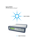
Agilent E5810A
LAN/GPIB Gateway for Windows®
User’s Guide
THIS PAGE HAS BEEN INTENTIONALLY LEFT BLANK.
Front Matter
Notice
The information contained in this document is subject to change without
notice.
Agilent Technologies shall not be liable for any errors contained in this
document. Agilent Technologies makes no warranties of any kind with
regard to this document, whether express or implied. Agilent Technologies
specifically disclaims the implied warranties of merchantability and fitness
for a particular purpose. Agilent Technologies shall not be liable for any
direct, indirect, special, incidental, or consequential damages, whether
based on contract, tort, or any other legal theory, in connection with the
furnishing of this document or the use of the information in this document.
Warranty Information
A copy of the specific warranty terms applicable to your Agilent Technologies
product and replacement parts (as applicable) is shipped with your product.
If the warranty terms are not included or if you want a copy
of the warranty terms, contact Agilent Technologies, Inc.
U.S. Government Restricted Rights
The Software and Documentation have been developed entirely at private
expense. They are delivered and licensed as "commercial computer
software" as defined in DFARS 252.227- 7013 (Oct 1988), DFARS 252.2117015 (May 1991) or DFARS 252.227-7014 (Jun 1995), as a "commercial
item" as defined in FAR 2.101(a), or as "Restricted computer software" as
defined in FAR 52.227-19 (Jun 1987) (or any equivalent agency regulation
or contract clause), whichever is applicable. You have only those rights
provided for such Software and Documentation by the applicable FAR or
DFARS clause or the Agilent standard software agreement for the product
involved.
3
Declaration of Conformity
The Declaration of Conformity (DoC) for this instrument is available on the
Agilent Web site. You can search the DoC by its product model or
description at the Web address below.
http://regulations.corporate.agilent.com/DoC/search.htm
NOTE
If you are unable to search for the respective DoC, please contact your
local Agilent representative.
4
ICES Statement
This ISM device complies with Canadian ICES-001.
Cet appareil ISM est conforme à la norme NMB-001 du Canada.
Regulatory Markings
The CE mark is a registered trademark
of the European Community. This CE
mark shows that the product complies
with all the relevant European Legal
Directives.
The C-tick mark is a registered
trademark of the Spectrum
Management Agency of Australia. This
signifies compliance with the Australia
EMC Framework regulations under the
terms of the Radio Communication Act
of 1992.
ICES/NMB-001 indicates that this ISM
device complies with the Canadian
ICES-001.
This instrument complies with the
WEEE Directive (2002/96/EC) marking
requirement. This affixed product label
indicates that you must not discard this
electrical or electronic product in
domestic household waste.
Cet appareil ISM est confomre a la
norme NMB-001 du Canada.
This symbol indicates the time period
during which no hazardous or toxic
substance elements are expected to
leak or deteriorate during normal use.
Forty years is the expected useful life of
the product.
The CSA mark is a registered
trademark of the Canadian Standards
Association.
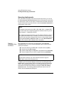
Safety Symbols
Instruction manual symbol affixed to
product. Indicates that the user must
refer to the manual for specific
WARNING or CAUTION information to
avoid personal injury or damage to the
product.
Alternating current (AC).
Direct current (DC).
Warning. Risk of electrical shock.
Indicates the field wiring terminal that
must be connected to earth ground
before operating the equipment —
protects against electrical shock in
case of fault.
or
Frame or chassis ground terminal—
typically connects to the equipment's
metal frame
WARNING
Calls attention to a procedure,
practice, or condition that could cause
bodily injury or death.
Calls attention to a procedure,
CAUTION practice, or condition that could
possibly cause damage to equipment
or permanent loss of data.
5
WARNINGS
The following general safety precautions must be observed during all
phases of operation, service, and repair of this product. Failure to comply
with these precautions or with specific warnings elsewhere in this manual
violates safety standards of design, manufacture, and intended use of the
product. Agilent Technologies assumes no liability for the customer's failure
to comply with these requirements.
Ground the equipment: For Safety Class 1 equipment (equipment having a
protective earth terminal), an uninterruptible safety earth ground must be
provided from the mains power source to the product input wiring terminals
or supplied power cable.
DO NOT operate the product in an explosive atmosphere or in the presence of
flammable gases or fumes.
For continued protection against fire, replace the line fuse(s) only with
fuse(s) of the same voltage and current rating and type. DO NOT use
repaired fuses or short-circuited fuse holders.
Keep away from live circuits: Operating personnel must not remove
equipment covers or shields. Procedures involving the removal of covers or
shields are for use by service-trained personnel only. Under certain
conditions, dangerous voltages may exist even with the equipment switched
off. To avoid dangerous electrical shock, DO NOT perform procedures
involving cover or shield removal unless you are qualified to do so.
DO NOT operate damaged equipment: Whenever it is possible that the safety
protection features built into this product have been impaired, either through
physical damage, excessive moisture, or any other reason, REMOVE
POWER and do not use the product until safe operation can be verified by
service-trained personnel. If necessary, return the product to Agilent for
service and repair to ensure that safety features are maintained.
DO NOT service or adjust alone: Do not attempt internal service or
adjustment unless another person, capable of rendering first aid and
resuscitation, is present.
DO NOT substitute parts or modify equipment: Because of the danger of
introducing additional hazards, do not install substitute parts or perform any
unauthorized modification to the product. Return the product to Agilent for
service and repair to ensure that safety features are maintained.
If the equipment is used in a manner not specified by the manufacturer, the
protection provided by the equipment may be impaired.
6
Documentation History
All Editions and Updates of this manual and their creation date are listed
below. The first Edition of the manual is Edition 1. The Edition number
increments by 1 whenever the manual is revised. Updates, which are issued
between Editions, contain replacement pages to correct or add additional
information to the current Edition of the manual. Whenever a new Edition is
created, it will contain all of the Update information for the previous Edition.
Each new Edition or Update also includes a revised copy of this
documentation history page.
Edition 1 . . . . . . . . . . . . . . . . . . . . . . . . . . . . . . . . . . . .
Edition 2 . . . . . . . . . . . . . . . . . . . . . . . . . . . . . . . . . . . .
Edition 3 . . . . . . . . . . . . . . . . . . . . . . . . . . . . . . . . . . . .
Edition 4 . . . . . . . . . . . . . . . . . . . . . . . . . . . . . . . . . . . .
Edition 5 . . . . . . . . . . . . . . . . . . . . . . . . . . . . . . . . . . . .
Edition 6 . . . . . . . . . . . . . . . . . . . . . . . . . . . . . . . . . . . .
Edition 7 . . . . . . . . . . . . . . . . . . . . . . . . . . . . . . . . . . . .
Edition 8 . . . . . . . . . . . . . . . . . . . . . . . . . . . . . . . . . . . .
Edition 9 . . . . . . . . . . . . . . . . . . . . . . . . . . . . . . . . . . . .
Edition 10 . . . . . . . . . . . . . . . . . . . . . . . . . . . . . . . . . . .
Edition 11 . . . . . . . . . . . . . . . . . . . . . . . . . . . . . . . . . . .
Edition 12 . . . . . . . . . . . . . . . . . . . . . . . . . . . . . . . . . . .
May 2002
December 2003
May 2004
January 2005
September 2007
June 19, 2009
July 20, 2009
August 4, 2011
January 1, 2012
September 24, 2012
March 19, 2013
October 8, 2013
Copyright Information
Agilent Technologies
E5810A LAN/GPIB Gateway for Windows User’s Guide
Copyright © 2002–2013 Agilent Technologies, Inc. All rights reserved.
Manual Part Number: E5810-90001
Support Information
Support information for the E5810A LAN/GPIB Gateway for Windows
follows. When calling Agilent with support questions, please have the
following information available so we can provide you with a quicker solution
to the problem.
E5810A Serial Number (printed on bottom of the unit and displayed
on the Welcome page of the E5810A Web access)
Description of the Problem
7
Corrective actions already tried (see Chapter 4 - Troubleshooting
Information for suggested troubleshooting tips)
Contacting Agilent
You can reach Agilent Technologies at this telephone number in the
Americas:
Americas Call Center:
1-800-829-4444
For other countries, contact your country’s Agilent support
organization. A list of contact information for other countries is
available on the Agilent Internet site:
www.agilent.com/find/assist
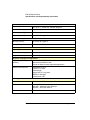
A list of other Agilent Web sites follows.
URL
Description
www.agilent.com/find/assist
Agilent Technologies “Contact us” page
www.agilent.com/find/e5810a
The latest E5810A product information with links to key
Web sites such as FAQs, Data Sheets, etc.
www.agilent.com/find/iolib
Update the Agilent IO Libraries Suite software
www.agilent.com/find/techsupport
The latest customer support information
www.agilent.com/find/ADN
Connectivity resources all in one place
www.agilent.com/find/manuals
Technical support information, including manuals,
application notes, FAQs, and software and firmware
downloads
www.agilent.com/find/connectivity
For connection, communication and control of test
instruments from your computer, you can find out the
latest in the world of connectivity.
User’s Guide Information
This Agilent E5810A LAN/GPIB Gateway for Windows User’s Guide
describes installation, configuration, and use of an E5810A LAN/GPIB
8
Gateway for Windows that is connected to an Enterprise (corporate)
network, to a Local Network, or directly to a PC.
NOTE
All Agilent IO Libraries information in this guide refers to
Agilent IO Libraries Suite version 15.0 or above. For specific information
on other versions of the Agilent IO Libraries or Agilent IO Libraries Suite,
see the documentation for that version. You can download both updates
and older versions (for backward compatibility) of the IO Libraries
software at http://www.agilent.com/find/iolib.
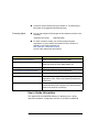
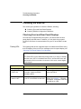
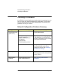
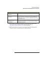
What’s in This
Guide?
A listing of the guide contents follows.
NOTE
This guide is NOT a tutorial on Local Area Networks (LANs) or specific
LAN operation. Consult your Information Technology (IT) department for
LAN specifics for your application.
Chapter
Description
Chapter 1, “E5810A
Description,”
Describes the E5810A, including hardware description and
network operation.
Chapter 2, “Installing the
E5810A,”
Shows how to install the E5810A and the
Agilent IO Libraries Suite.
Chapter 3, “Using E5810A Web
Access,”
Shows how to use the E5810A Web access to interface with
the E5810A from your PC.
Chapter 4, “Troubleshooting
Information,”
Shows some ways to troubleshoot the E5810A, including
front panel, network, PC client, and instrument checks.
Appendix A, “E5810A
Specifications,”
Provides specifications for the E5810A.
Appendix B, “Using the Telnet
Utility,”
Provides a summary of using the Telnet utility.
“Glossary”
Defines some of the technical terms used in this guide.
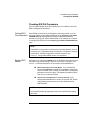
9
Accessing an
Electronic Copy of
This Guide
There are three ways you can access an electronic (.pdf) version of this
guide, as follows. You will need Adobe Acrobat Reader Version 3.0 or later
to view the electronic version.
Access From the E5810A Web Access. After the E5810A is installed,
you can access an electronic version of the manual by going to the
Welcome page and clicking User’s Guide (under the E5810A
Documentation heading).
Access from the IO Control. If the Agilent IO Libraries Suite is
installed, a blue circled IO icon appears on the right hand side of the
Windows toolbar. To access an electronic version of this guide, click
the IO icon, then click Documentation and then click E5810A LAN/
GPIB Users Guide.
Access from the Web. On your Web browser address line, type:
www.agilent.com/find/manuals and navigate to the E5810A
manual.
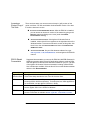
E5810A Related
Documentation
Suggested documentation you can use for E5810A LAN/GPIB Gateway for
Windows operation with the listed I/O application software products follow.
After the Agilent IO Libraries Suite has been installed on your PC, .pdf files
of the Agilent IO Libraries Suite documentation including VISA and SICL
User’s Guides are available. Click the blue IO icon on the Windows taskbar
and then click Documentation.
Product
Related Documentation
Agilent IO
Libraries Suite
The Agilent IO Libraries Suite Getting Started Guide and the IO Libraries
Suite Online Help describe the use of the IO Libraries Suite.
VISA
To use the E5810A with VISA, you must configure a remote interface (also
known as VISA LAN Client operation). To develop and use VISA applications
for the E5810A, see the Agilent VISA User’s Guide.
SICL
To develop and use SICL I/O applications for the E5810A in Windows,
see the Agilent SICL User’s Guide for Windows.
T&M Toolkit
To develop programs in Visual Studio .NET, see the Agilent T&M Toolkit
product. Information is available at www.agilent.com/find/toolkit.
10
Table of Contents
1 E5810A Description
E5810 Hardware Description ....................................................... 15
Typical Network Connections ............................................... 15
Front Panel Features ............................................................ 17
Rear Panel Features ............................................................ 21
Rack Mount Kit (Optional) .................................................... 21
E5810A Software/Firmware ......................................................... 22
E5810A Operating Features ................................................. 23
Typical Network Operation ................................................... 24
Software/Firmware Architecture ........................................... 25
Typical Network IP Addressing ............................................ 27
Communicating with the E5810A ......................................... 29
2 Installing the E5810A
Installation Flowchart ................................................................... 35
Before You Install the E5810A..................................................... 37
Check Shipment Items ......................................................... 37
Rack-Mount the E5810 (Optional) ........................................ 38
Getting Network Information ........................................................ 39
Getting Enterprise Network Information ............................... 39
Getting Local Network Information ....................................... 39
Configuring the E5810A on a Local Network ............................... 41
What is a Local Network? ..................................................... 41
Connecting the E5810A to a Local Network ......................... 43
Configuring the E5810A for Local Network Operation ......... 46
Installing the E5810A on an Enterprise Network ......................... 52
Connecting the E5810 to the Network .................................. 52
Configuring the E5810A for Enterprise Network Operation .. 53
Verifying Instrument Communication ........................................... 58
Open the Instrument Page ................................................... 58
Instrument Page Functions .................................................. 59
Installing and Configuring Agilent IO Libraries Suite.................... 61
Configuring a Remote GPIB Interface .................................. 63
Configuring a Remote Serial Interface ................................. 65
Verifying Communication From Your PC ............................. 68
Programming Instruments .................................................... 69
3 Using E5810A Web Access
Opening Your Web Browser for E5810A Web Access ................ 75
Using the Welcome Page ............................................................ 76
Navigation Bar ...................................................................... 77
E5810A Current Settings ...................................................... 78
Table of Contents
11
E5810A Support Information .................................................79
E5810A Documentation ........................................................80
Viewing and Modifying Configuration ...........................................81
Viewing E5810A Configuration .............................................81
Modifying E5810A Configuration ..........................................82
Finding and Querying Instruments ...............................................92
Finding Instruments ..............................................................93
Querying Instruments ............................................................94
Other Web Access Functions .......................................................97
Determining Session Status ..................................................97
Using Web Help ....................................................................98
Updating E5810A Firmware ..................................................99
4 Troubleshooting Information
Troubleshooting Overview..........................................................109
Checking the E5810A................................................................. 110
Checking Front and Rear Panel Displays ........................... 110
Checking E5810A Parameters ............................................ 113
Checking the Network ................................................................ 114
Network Configuration Problems Summary ........................ 114
Checking Web Browser Settings ........................................ 115
Checking Other Network Problems ..................................... 117
Checking PC Client Connections ............................................... 119
Verifying PC Client Connections ......................................... 119
Checking syslog Messages ................................................121
Runtime Error Messages ....................................................124
Checking Instruments.................................................................127
Checking GPIB Instruments ................................................127
Checking RS-232 Instruments ............................................128
A E5810A Specifications
Specifications and Supplementary Information ..........................131
Supported Network Protocols.....................................................134
B Using the Telnet Utility
Using the Telnet Utility................................................................137
Telnet Commands for the E5810A .............................................140
Glossary
12
Table of Contents
1
E5810A Description
E5810A Description
This chapter gives guidelines to install, configure, and troubleshoot the
E5810A LAN/GPIB Gateway for Windows (E5810) for use with supported,
network-equipped computer systems, including:
E5810 Hardware Description
E5810 Software/Firmware
14
Chapter 1
E5810A Description
E5810 Hardware Description
E5810 Hardware Description
The E5810 LAN/GPIB Gateway for Windows provides a gateway between
network-equipped computer systems and GPIB and/or RS-232 based
instruments. This section provides an overview of E5810 hardware,
including:
Typical Network Connections
Front Panel Features
Rear Panel Features
Power-On and Default Settings
Rack Mount Kit (Optional)
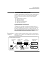
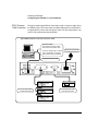
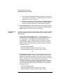
Typical Network Connections
The E5810 can be connected to an Enterprise (corporate) network, to a
Local network (isolated LAN), or directly to a PC and can be connected to
as many as 14 GPIB instruments and/or to one RS-232 instrument. The
E5810 allows I/O applications to obtain measurement data either locally or
remotely from GPIB and/or RS-232 instrumentation. The following figures
show typical network and direct PC connections to an E5810.
Enterprise Network
Connections
In a typical Enterprise (corporate) network, the E5810 is connected to the
network by a router or switch. For this configuration, the E5810 is visible to
the Enterprise network.
Enterprise Network Connections
To Enterprise
Network
Typically Router
or Switch
E5810
LAN GPIB RS232
GPIB Instruments
GPIB Ports
GPIB
GPIB
LAN
Patch
Cables
Chapter 1
To RS-232
Instrument
GPIB
15
E5810A Description
E5810 Hardware Description
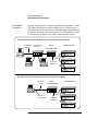
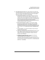
Local Network
Connections
Typically, a hub or switch is used for local network configuration. A cable/
DSL router may be used to provide a DHCP Server. For typical direct
connections from a PC to the E5810, a crossover cable is connected from
the E5810 LAN port to a LAN card on the PC. For Local Network or direct
PC connections, the E5810 is not visible on the Enterprise network.
Local Network Connections (Multiple PCs can Communicate with the E5810)
LAN Patch
Cable
Typically Hub
or Switch
E5810
GPIB Instruments
LAN GPIB RS232
GPIB
GPIB
GPIB
To RS-232
Instrument
GPIB
Direct PC Connection (Only One PC can Communicate with the E5810)
Crossover
Cable
GPIB Instruments
E5810
LAN GPIB RS232
GPIB
Connect to
PC LAN Card
GPIB
To RS-232
Instrument
GPIB
GPIB
16
Chapter 1
E5810A Description
E5810 Hardware Description
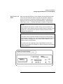
Front Panel Features
This section describes the E5810 front panel features,
NOTE
The Hostname, if detected, is displayed on the first line of the E5810 front
panel display. The IP Address of the E5810 is displayed on the second
line of the E5810 front panel display.
Front Panel
Display/LEDs
This figure shows E5810 front panel functions.
Preset Button
Depressing for <10 sec temporarily resets only
the default password (E5810). Depressing for
>10 sec resets all parameters to factory default
values and reboots the E5810.
Display
A 16-character, two-line display
that displays the Hostname (if
known) and the IP Address plus
system messages.
E5810A
LAN/GPIB Gateway
agiltb6
169.254.58.10
Power
Activity
LAN GPIB RS232
Power LED
When ON (Green), shows AC
power is applied to the E5810.
LAN LED
Flashes for activity on the LAN.
Fault
Preset
Fault LED
If ON (RED) for >10 sec,
indicates possible hardware
failure. Briefly turns ON at
power-on while the E5810
is running its self-test.
GPIB LED
Flashes for GPIB instrument activity.
RS232 LED
Flashes for RS-232 instrument activity.
Chapter 1
17
E5810A Description
E5810 Hardware Description
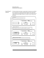
Typical Power-On
Sequence
This figure shows major steps in a typical power-on sequence for an E5810
that is connected to a network that supports Dynamic Host Configuration
Protocol (DHCP) and Domain Name Service (DNS). If the network does not
support DHCP and/or DNS, the power-on sequence may be different than
that shown.
Power Applied
Display is blank, Power (Green) and Fault (Red) are ON.
E5810A
LAN/GPIB Gateway
Power
Activity
LAN GPIB RS232
Fault
Preset
Searching for DHCP Server
Display displays message, Power (Green) is ON and Fault (Red) is OFF. This typically takes
20 to 30 seconds and can take up to 150 seconds if a DHCP Server is not present.
E5810A
LAN/GPIB Gateway
Searching for
169.254.58.10
DHCP Server...
Power
Activity
LAN GPIB RS232
Fault
Preset
IP Address and Hostname Displayed
Display displays Hostname, (if known) and IP address, only Power (Green) is ON.
E5810A
LAN/GPIB Gateway
Hostname
IP Address
18
Power
Activity
LAN GPIB RS232
Fault
Preset
Chapter 1
E5810A Description
E5810 Hardware Description
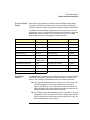
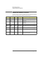
Power-On (Default) When power is first applied to the E5810 and the hardware self-test has
completed, the E5810 is initialized to the factory-set default configuration.
Settings
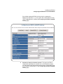
This table shows the default configuration parameter settings for the E5810.
The E5810 uses these default configuration values until you set any other
configuration values. The E5810 also uses these values when you press the
Preset button and hold it down for >10 seconds. See Chapter 3, “Using
E5810A Web Access” for a description of each parameter.
Parameter
Default
Parameter
Default
DHCP:
ON
GPIB Address:
21
IP Address:
169.254.58.10
GPIB Logical Unit:
7
Subnet Mask:
255.255.0.0
RS-232 SICL Interface Name:
COM1
Default Gateway:
0.0.0.0
RS-232 Baud Rate:
9600
DNS Server(s):
0.0.0.0
RS-232 Parity:
NONE
RS-232 Bits:
8
Hostname:
none
Description:
Agilent E5810
<MAC Addr>
RS-232 Stop Bits:
1
Universal Plug & Play:
ON
RS-232 Flow Control:
NONE
LAN Keepalive (sec):
7200 sec
RS-232 SRQ:
RI
I/O Timeout (sec):
120 sec
Password
E5810
GPIB SICL Interface Name:
gpib0
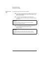
Preset Button
Operation
The Preset button on the front panel of the E5810 is used to reset the E5810
to its default configuration values (preset at the factory). As shown in the
figure on the next page, the Preset button has two modes of operation:
If you depress the Preset button and release it in <10 seconds, only
the E5810 password is temporarily changed and is reset to its
default value (E5810). If you cycle power or reboot the E5810, the
E5810 will return to the actual password that was previously set. All
existing configuration values remain unchanged.
If you depress and hold the Preset button for 10 seconds or more, all
configuration values are reset to their factory default values and the
E5810 is rebooted. All network connections to the E5810, if any, are
also terminated without any cleanups.
Chapter 1
19
E5810A Description
E5810 Hardware Description
Depress and Quickly (<10 seconds) Release the Preset Button *
-
The E5810 password is temporarily reset to its factory default (E5810).
All other configuration parameters remain unchanged.
This state is maintained until the next time the E5810 is booted.
The front panel display sequence is as follows.
Hostname
IP Address
Temporary Password = "E5810"
* Release the Preset button when Temporary Password = "E5810" is displayed.
Depress and Hold the Preset Button (>10 Seconds)**
- All configuration parameters are set to their default values.
- The E5810 is rebooted.
- The front panel display sequence is as follows.
Hostname
IP Address
Temporary Password = "E5810"
Hostname
IP Address
Hold to Reboot
& Set Defaults
Setting Factory
Defaults
Rebooting
E5810...
** Release the Preset button when Rebooting E5810... is displayed.
20
Chapter 1
E5810A Description
E5810 Hardware Description
Rear Panel Features
This figure shows the rear panel features of the E5810.
LAN Port
Connect one end of a LAN patch
cable to this port and connect
the other end of the cable to a
router/hub/switch.
OR
Connect one end of a crossover
cable to this port and the other
end of the cable to a LAN card
on your PC.
GPIB Port
Connect one end of GPIB
cable to this port and connect
other end of cable to a GPIB
instrument.
LAN Activity Lights
When the green Ln light is ON, the E5810
is successfully connected to the LAN. When
the green Tx light flashes, the E5810 is
transmitting data onto the LAN.
Serial Number and Ethernet Address
The E5810 Serial Number and Ethernet
(MAC) Address are printed on a label on
the underside of the E5810.
RS232 Port
Connect one end of RS-232
cable to this port and connect
other end of cable to an
RS-232 instrument.
POWER Port
Connect AC power cord to this
port and plug cord into an AC
outlet. The E5810 does not
have a power switch. The Mains
disconnect is to unplug the AC
power cord from the AC outlet.
The power supply automatically
conforms to the input voltage
and frequency supplied, within
100V - 240V (±10%) @ 47-63 Hz.
Rack Mount Kit (Optional)
As desired, you can mount up to two E5810 in a standard EIA rack using the
E5810 Rack Mount Kit (E5810 Opt 100 or E5810-00100). The E5810 is one
standard half-rack unit wide and one standard rack unit high. See the
E5810-00100 Rack Mount Kit for installation instructions.
Chapter 1
21
E5810A Description
E5810A Software/Firmware
E5810A Software/Firmware
The E5810 LAN/GPIB Gateway for Windows provides an interface
(gateway) that allows networked computers to talk or listen to GPIB and/or
RS-232 devices via Local Area Network (LAN) connections. The E5810
connects a network (Enterprise or Local) from PCs with Windows XP/Vista/
7/8/Server 2008 R2 to GPIB and/or RS-232 instruments. This section
describes E5810 software/firmware features, including:
22
E5810 Operating Features
Typical Network Operation
Software/Firmware Architecture
Typical Network IP Addressing
Communicating with the E5810
Chapter 1
E5810A Description
E5810A Software/Firmware
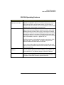
E5810A Operating Features
Feature
Description
Remote access to
instruments via LAN
Access and control up to 14 GPIB and/or one RS-232 instrument via a
10BASE-T/100BASE-TX Ethernet. The E5810 detects the network
and configures itself to the appropriate speed. The E5810 has a
standard RJ-45 LAN connector. You can use adapters to connect other
interface types, such as optical or wireless LAN.
I/O Software Included
The E5810 includes the Agilent IO Libraries Suite, which includes
Agilent Virtual Instrument Software Architecture (VISA), VISA COM,
Standard Instrument Control Library (SICL), and several I/O utilities.
This standard software provides compatibility with different hardware
and software vendors. It provides the I/O software layer used when
accessing the E5810. You can use a standard programming language,
such as Visual Basic, Visual C++, Agilent VEE, etc.
The E5810 supports all I/O application operations provided by VISA,
VISA COM, SICL, and Agilent VEE. The E5810 is supported on
Microsoft Windows XP/Vista/7/8/Server 2008 R2.
You can also use the Agilent IntuiLink software (included with some
Agilent products) to download data and send waveforms to the source,
with no programming.
Supports DHCP
Protocol
The E5810 supports Dynamic Host Configuration Protocol (DHCP) to
get its IP address. Although the E5810 defaults to using DHCP, you
can turn DHCP OFF and statically assign the E5810 IP address.
Ease of Use
Built-in Web access and front panel display allow you to easily set up,
configure, and use the E5810. You can connect multiple E5810s in a
test system. Each E5810 creates a separate GPIB bus.
Chapter 1
23
E5810A Description
E5810A Software/Firmware
Typical Network Operation
The E5810 provides a network gateway between network-equipped
computer systems and GPIB and/or RS-232 based instruments. The
gateway enables users to obtain measurement data either locally or
remotely from GPIB and/or RS-232 instruments. See “Typical Network
Connections” in this chapter for typical connections to Enterprise or Local
Networks or to a PC.
The E5810 connects a local area network (LAN) from the computer system
to the GPIB and/or RS-232 buses. Network-equipped computer systems
that are supported for use with the E5810 include PCs with Windows XP/
Vista/7/8/Server 2008 R2. Using the client/server model of computing, the
computer system is the client, and the E5810 is the server.
Client System
Server
E5810
LAN
GPIB Instruments
GPIB
RS-232 Instrument
RS-232
Thus, applications running on the computer system can transparently
interface to GPIB and RS-232 based instruments over the LAN. Since
several computer systems can access the E5810, groups of users can share
access to the same GPIB and/or RS-232 instruments via the E5810. In
addition, existing I/O applications that are supported with the E5810 and are
designed for GPIB or RS-232 can use the E5810 without modification other
than an address change.
The E5810 and its attached instruments can be placed anywhere on the
network (rather than with a particular controller or server computer system).
This includes networks which span different geographic locations, such as
when networked computer systems are located at several different sites.
Thus, GPIB and RS-232 instruments can be located where they are most
convenient. In addition, you can have more than one E5810 on a network,
providing “clusters” of GPIB and/or RS-232 instrumentation at different
locations.
24
Chapter 1
E5810A Description
E5810A Software/Firmware
Software/Firmware Architecture
To program instruments from your PC via the E5810 using a programming
language such as C or Visual Basic, you must install and configure the
Agilent IO Libraries Suite on the client PC.
Client System
Architecture
As shown in the following figure, the client (PC) system contains the VISA
LAN client software as well as the TCP/IP LAN software needed to access
the E5810. The E5810 contains LAN server and TCP/IP LAN firmware so it
acts as the LAN server.
The VISA LAN client software is also known as the Remote IO Client
software. It is part of the Agilent IO Libraries Suite. The LAN server software
is also called the Remote IO Server software.
The VISA LAN client software uses the TCP/IP LAN protocol suite to pass
messages between the client system and the server (the E5810). Therefore,
the client sends I/O requests over the network to the server. The server then
executes those I/O requests on the appropriate GPIB and/or RS-232 based
instrument(s) connected to the server.
Client System
Server (E5810)
Application
LAN Server
Agilent VISA
TCP
SICL
IP
LAN Client
Instrument
Instrument
Firmware
I/O
Driver
LAN Interface
TCP
IP
LAN Interface
Chapter 1
GPIB or RS-232 bus
25
E5810A Description
E5810A Software/Firmware
How IO Application
Software Works
With the E5810
Before trying to perform an I/O application operation on the E5810 GPIB
interface and the GPIB bus, the Remote IO Client software in the client
computer system establishes a network connection to the remote I/O server
(the E5810). Once the client establishes a connection, the client can begin to
send I/O requests to the E5810.
The E5810 (remote I/O server) can have multiple clients connected and
being serviced at any given time. The maximum number of concurrent client
connections depends on memory usage in the E5810, including the number
of clients and the number of current sessions running on those clients.
However, up to 16 client connections can be running concurrently. Thus, if
the maximum number of client connections to the E5810 has not been
exceeded, the connection is allowed to occur.
Although several instruments can be connected to the E5810 GPIB bus,
only one I/O application operation can occur on the GPIB bus at any given
time. Therefore, once a client’s request begins to execute on the GPIB, all
other client requests for operations on the GPIB must wait until the current
client request completes. Client requests are serviced in a first come, first
served manner, unless they are prohibited by interface or device locks.
If a client has a sequence of I/O application operations to perform that
should not be preempted, the client should obtain a lock on the E5810 GPIB
interface or device. Once the client’s sequence has completed, it should
release its lock, allowing access for other clients.
When a client closes a connection, the E5810 frees up the resources
allocated to that client, including any locks, pending I/O requests, memory
usage, etc.
26
Chapter 1
E5810A Description
E5810A Software/Firmware
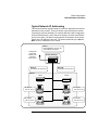
Typical Network IP Addressing
This section describes typical Enterprise network IP addresses and subnet
addresses on the network. This figure shows a typical Enterprise network,
consisting of a Router (Gateway), a corporate Dynamic Host Configuration
Protocol (DHCP) Server, and a subnet consisting of six hosts (two E5810s
and four host PCs.) The Router sends packets of information to each host,
based on the IP address of the host. The subnet is defined by the Subnet
Mask for the IP addresses on the subnet.
Router
Default Gateway: 156.140.104.1
Subnet Mask: 255.255.0.0
To Enterprise
(Corporate)
Network and
Corporate
DHCP Server
Router (Gateway)
E5810 #1
IP Address 156.140.104.72
E5810 #2
IP Address 156.140.104.75
Subnet
E5810
E5810
Host PC
Host PC
IP Address
156.140.104.73
IP Address
156.140.104.76
Host PC
IP Address
156.140.104.74
Chapter 1
Host PC
IP Address
156.140.104.77
27
E5810A Description
E5810A Software/Firmware
Subnet Addressing
A Subnet Mask is used to determine to which subnet an IP address belongs.
An IP address has two components: the network address and the host
address. For example, assuming IP address 156.215.117.109 is part of a
Class B network, the first two numbers (156.215) represent the Class B
network address and the second two numbers (117.109) identify a specific
host on this network. See the Glossary for a description of a Class B
network.
For the subnet in the figure, an example IP address for E5810 #1 is
156.140.104.72, where 156.140 represents the network address and 104.72
represents the E5810 #1 host address. An example IP address for E5810 #2
is 156.140.104.75, where 156.140 represents the network address and
104.75 represents the E5810 #2 host address.
E5810 IP Address
Assignment
For the E5810 to operate on an Enterprise network, three addresses must
be identified: E5810 IP Address, Subnet Mask, and Default Gateway
Address.
If the Enterprise network supports Dynamic Host Configuration Protocol
(DHCP), the E5810 will automatically receive an IP address, Subnet Mask,
and Default Gateway from the DHCP Server. If the network does not support
DHCP, the E5810 IP address must be configured manually.
In addition, if the network supports Domain Name Service (DNS), an E5810
Hostname can be configured. This can be done in one of two ways:
The DNS Server IP Address is provided by the DHCP Server (this is
transparent to the user).
A DNS Server IP address is supplied by the System Administrator
and entered on the Configuring your E5810 LAN/GPIB Gateway page.
28
Chapter 1
E5810A Description
E5810A Software/Firmware
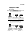
Communicating with the E5810A
There are two ways you can communicate with the E5810 via a network: use
the E5810 Web access or use a supported programming language with the
Agilent IO Libraries Suite.
Using the E5810 Web Access
Agilent IO Libraries Are Not Required
PC
LAN
Use a supported Web
Browser to access and
configure the E5810.
E5810
The E5810 provides a
Web Server that allows
for access via the Web.
GPIB
Instruments
Instruments are programmed
using standard instrument
commands (such as SCPI)
via the Web browser.
Using Supported Programming Languages
Agilent IO Libraries Are Required
PC
To program connected
instruments, you must
install and configure the
Agilent IO Libraries Suite
on your PC.
Chapter 1
LAN
E5810
The interface must be
configured for VISA
LAN Client operation.
GPIB
Instruments
Program instruments
using a supported
programming language
(such as C, etc.) and
VISA or SICL.
29
E5810A Description
E5810A Software/Firmware
Using E5810 Web
Access
Since the E5810 is Web-enabled, you can communicate with the E5810
from a supported Web browser. The E5810 supports Internet Explorer 6.0 or
greater. Typing in the E5810 IP address (or E5810 hostname, if known) on
your Web browser address line and then pressing the Enter key displays the
E5810 Welcome page.
You can use the Web access to configure the E5810 and to communicate
with GPIB and/or RS-232 instruments. For example, using the Configuring
your E5810 LAN/GPIB Gateway page of the E5810 interface, you can view
and modify the configuration of the E5810. Or, you can communicate with
installed GPIB and/or RS-232 instruments using the Find and Control
Instruments Connected to your E5810 page of the interface. See Chapter 3,
“Using E5810A Web Access” for information on E5810 Web access.
30
Chapter 1
E5810A Description
E5810A Software/Firmware
Using a Supported
Programming
Language
To use applications that require the Agilent IO Libraries, you must install and
configure the Agilent IO Libraries Suite on each PC to be used for
programming. Then, you can program connected instruments using a
supported programming language (such as C or Visual Basic) using the
Agilent Virtual Instrument Software Architecture (VISA), VISA COM, or
Standard Instrument Control Language (SICL). See the Agilent IO Libraries
Suite Getting Started Guide and Agilent IO Libraries Suite Online Help for
more information on the Agilent IO Libraries.
Chapter 1
31
E5810A Description
E5810A Software/Firmware
Notes:
32
Chapter 1
2
Installing the E5810A
Installing the E5810A
This chapter shows suggested steps to install the Agilent E5810A LAN/GPIB
Gateway for Windows on LAN networks for Windows PCs, including:
Installation Flowchart
Before You Install the E5810A
Getting Network Information
Configuring the E5810A on a Local Network
Installing the E5810A on an Enterprise Network
Verifying Instrument Communication
Installing and Configuring Agilent IO Libraries Suite
NOTE
All Agilent IO Libraries information in this guide refers to
Agilent IO Libraries Suite version 15.0 or above. For specific information
on other versions of the Agilent IO Libraries or Agilent IO Libraries Suite,
see the documentation for that version. You can download both updates
and older versions (for backward compatibility) of the IO Libraries
software at http://www.agilent.com/find/iolib.
The Agilent E5810 is supported with PCs running Windows XP/Vista/7/8/
Server 2008 R2 operating systems.
34
Chapter 2
Installing the E5810A
Installation Flowchart
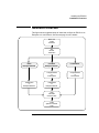
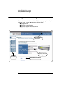
Installation Flowchart
This figure shows suggested steps to install and configure an E5810 on an
Enterprise or Local network. See the next page for more details.
Before You
Install
the E5810
Get
Network
Information
DHCP
Enterprise Network
non-DHCP
Enterprise Network
Configure E5810
on
Local Network
Install E5810
on
Enterprise Network
Local Network
Configure E5810
on
Local Network
Install E5810
on
Enterprise Network
Verify
Instrument
Communication
Install
Agilent IO Libraries
Suite
Chapter 2
35
Installing the E5810A
Installation Flowchart
You can install the E5810 on an Enterprise (corporate) network that supports
Dynamic Host Configuration Protocol (DHCP), an Enterprise network that
does not support DHCP, or a Local network.
NOTE
If you plan to install the E5810 on an Enterprise network, contact your
Information Technology (IT) Department to see if the network supports
Dynamic Host Configuration Protocol (DHCP).
Installing the E5810 See these sections to install an E5810 on an Enterprise network that does
support DHCP:
on a DHCP
Enterprise Network
Before You Install the E5810A
Getting Network Information
Installing the E5810A on an Enterprise Network
Verifying Instrument Communication
Installing and Configuring Agilent IO Libraries Suite
Installing the E5810 To install the E5810 on an Enterprise network that does not support DHCP,
on a non-DHCP
you may need to first configure the E5810 on a Local network and then
Enterprise Network install the E5810 on the Enterprise network. See these sections to install an
E5810 on an Enterprise network that does not support DHCP:
Before You Install the E5810A
Getting Network Information
Configuring the E5810A on a Local Network
Installing the E5810A on an Enterprise Network
Verifying Instrument Communication
Installing and Configuring Agilent IO Libraries Suite
Installing the E5810 If you plan to install the E5810 on a Local network, you may not need to
on a Local Network contact your IT department. However, you will need to determine network
parameters. See these sections to install and configure an E5810 on a Local
network:
36
Before You Install the E5810A
Getting Network Information
Configuring the E5810A on a Local Network
Verifying Instrument Communication
Installing and Configuring Agilent IO Libraries Suite
Chapter 2
Installing the E5810A
Before You Install the E5810A
Before You Install the E5810A
Before you connect the E5810A to a network, you should:
Check Shipment Items
Rack Mount the E5810A (Optional)
Check Shipment Items
In addition to this E5810 LAN/GPIB Gateway for Windows User’s Guide,
your E5810 shipment should include the items shown in the following figure.
If any items are missing or damaged, contact Agilent Technologies. See
“Support Information” in the Front Matter of this guide for addresses.
E5810 LAN/GPIB Gateway for Windows
AC Power Cord
Appropriate AC power cord
for your country.
Rack Mount Kit (Optional)
E5810-00100 Rack Mount Kit
Agilent AutomationReady CD
E5810 Documentation
- E5810 Getting Started Poster
- E5810 User's Guide
- E5810 Warranty Statement
- Software License Agreement
Chapter 2
37
Installing the E5810A
Before You Install the E5810A
Rack-Mount the E5810 (Optional)
As desired, you can mount up to two E5810s in a single standard EIA rack
space using the E5810 Rack Mount Kit (E5810 Option 100 or
E5810-00100). The E5810 is one standard half-rack unit wide and one
standard rack unit high. See the E5810-00100 Rack Mount Kit for installation
instructions.
NOTE
You may want to configure the E5810 and ensure proper operation on the
Enterprise or Local network before rack-mounting the unit.
38
Chapter 2
Installing the E5810A
Getting Network Information
Getting Network Information
This section gives guidelines to get information about Enterprise and Local
networks, as applicable to your requirements.
Getting Enterprise Network Information
Before you connect the E5810 to an Enterprise (corporate) network, you will
need to get some network configuration and network addressing parameters
from the System Administrator in your Information Technology (IT)
department.
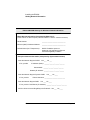
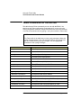
Copy the Network
Information Card
Make a copy of the E5810 Network Information Card shown on the next
page. Then, enter the E5810 Serial Number and Ethernet (MAC) Hardware
Address on the card.The E5810 Serial Number and Ethernet (MAC)
Address are printed on a label on the underside of the E5810. See the
Glossary for descriptions of the items on the Network Information card.
Contact Your
System
Administrator
Tell your system administrator you want to add a new device (the E5810) to
the network that will provide remote access for GPIB and RS-232
instruments and ask him/her to provide the applicable network information
on the E5810 Network Information Card. In addition to the E5810 Serial
Number and Ethernet Address, tell the System Administrator about the
E5810 (default) information listed on the card.
Getting Local Network Information
For installation on a Local network, you will probably not need to contact
your IT department. However, you should have all the required network
information available, such as IP addresses, etc.
Where to Go Next
To Install the E5810 on a DHCP Enterprise Network: Go to “Installing
the E5810A on an Enterprise Network”.
To Install the E5810 on a Non-DHCP Enterprise Network: Go to
“Configuring the E5810A on a Local Network”.
To Install the E5810 on a Local Network: Go to “Configuring the
E5810A on a Local Network”.
Chapter 2
39
Installing the E5810A
Getting Network Information
E5810 LAN/GPIB Gateway for Windows Network Information
E5810 General Information (Completed by E5810 User)
(Serial Number and Ethernet (MAC) Hardware Address on label on underside of E5810)
Serial Number:
______________________________
Ethernet (MAC) Hardware Address:
______________________________
Default Values (for IT Department):
DHCP: Enabled at power-on
Hostname: No hostname configured
Universal Plug&Play: Enabled
Enterprise Network Information (Completed by System Administrator)
Does the Network Support DHCP? Yes ___ No ___
If No, provide:
IP Address (Static): ______.______.______.______
Subnet Mask: ______.______.______.______
Gateway IP Address: ______.______.______.______
Does the Network Support Dynamic DNS?
If Yes, provide:
Yes ___ No ____
E5810 Hostname: __________________________
Does the Network Support DNS?
Yes ___ No ____
If Yes, provide: DNS Server (IP Address): ______.______.______.______
Will You Allow Universal Plug&Play to be Enabled? Yes ___ No ____
40
Chapter 2
Installing the E5810A
Configuring the E5810A on a Local Network
Configuring the E5810A on a Local Network
This step gives guidelines to configure an E5810 on a Local network for
eventual operation in a non-DHCP Enterprise network or in a Local network
operation, including:
What is a Local Network?
Connecting the E5810 to a Local Network
Configuring the E5810 on a Local Network
NOTE
This step gives guidelines to configure your E5810 on a Local network
for eventual installation on an Enterprise network that does not support
Dynamic Host Configuration Protocol (DHCP) OR for installation on a
Local network.
If you plan to install the E5810 on an Enterprise network that does
support DHCP, skip this step and go to “Installing the E5810 on an
Enterprise Network”.
What is a Local Network?
A local (peer-to-peer) network is a network consisting of a computer with an
Ethernet port and an E5810 or a set of networking devices that are
networked together but are not connected to an Enterprise network. The
figure on the next page shows example configurations for Local networks
with hub/switch or crossover cable connections.
Local Network
(Hub/Switch)
Connections
In a typical Local network (isolated LAN), a hub or switch may or may not act
as a Dynamic Host Configuration Protocol (DHCP) Server. For Local
Network connections, the E5810 is not visible on the Enterprise network. For
this configuration, multiple PCs can communicate with the E5810 via the hub
or switch.
Direct PC
(Crossover Cable)
Connections
For direct PC connection to the E5810, a crossover cable is connected from
the E5810 LAN port to a LAN card on the PC. There are no connections to
an Enterprise network. This setup is typically used for local configuration.
For this configuration, only a single PC can communicate with the E5810 via
the crossover cable.
Chapter 2
41
Installing the E5810A
Configuring the E5810A on a Local Network
Local Network Connections (Multiple PCs can Communicate with the E5810)
LAN Patch
Cable
Typically Hub
or Switch
E5810
GPIB Instruments
LAN GPIB RS232
GPIB
GPIB
GPIB
To RS-232
Instrument
GPIB
Direct PC Connection (Only One PC can Communicate with the E5810)
Crossover
Cable
GPIB Instruments
E5810
LAN GPIB RS232
GPIB
Connect to
PC LAN Card
GPIB
To RS-232
Instrument
GPIB
GPIB
42
Chapter 2
Installing the E5810A
Configuring the E5810A on a Local Network
Connecting the E5810A to a Local Network
This section shows how to connect the E5810 to a Local network using an
Ethernet hub/switch or a crossover cable.
E5810 Hub/Switch
Connections
This figure shows typical E5810 Ethernet hub or switch connections. Since
the E5810 has no AC Power switch, the Mains disconnect for the E5810 is
to unplug the AC power cord from the AC outlet.
Typical Local Network Connections (Hub/Switch) (Two PCs)
Ethernet Hub/Switch
1. Connect LAN patch
cables (do NOT use
crossover cables)
4. Connect to AC Power
2. Connect GPIB Cable
to GPIB Instrument(s)
GPIB
GPIB
Chapter 2
3. Connect RS-232 Cable
to RS-232 Instrument
43
Installing the E5810A
Configuring the E5810A on a Local Network
E5810 Crossover
Cable Connections
This figure shows typical E5810 connections using a crossover cable. Since
the E5810 has no AC Power switch, the Mains disconnect for the E5810 is
to unplug the AC power cord from the AC outlet. For this configuration, only
one PC can communicate with the E5810.
Typical E5810 Hardware Connections (Crossover Cable)
Crossover Cable
User-supplied crossover cable.
Do NOT use LAN "patch" cable.
Crossover cables swap Tx and Rx
lines to enable device communication without using a hub/switch.
4. Connect to AC Power
1. Connect Crossover Cable
GPIB
2. Connect GPIB Cable
to GPIB Instrument(s)
GPIB
3. Connect RS-232 Cable
to RS-232 Instrument
GPIB
44
Chapter 2
Installing the E5810A
Configuring the E5810A on a Local Network
Apply Power to the
E5810
After connecting the E5810 to a Local network, plug the E5810 AC power
cord into an AC outlet and observe the power-on sequence. When the
power-on sequence is complete, the default IP address of the E5810 is
displayed on the second line of the front panel display. A typical display
follows. See Chapter 1, “E5810A Description” for power-on sequences.
NOTE
Local networks may not have a DHCP Server. Since, by default, the
E5810 tries to find a DHCP server until a timeout value is reached, it may
require up to 75 seconds for the E5810 to display its default static IP
address (169.254.58.10).
NOTE
The E5810 detects duplicate IP addresses and will not start operation if
its IP address is already in use. If you try to simultaneously attach multiple
E5810s without changing each unit’s default static IP address, some
E5810s may not start operation.
To prevent this from happening, add a single E5810 at a time to the
network and configure each E5810 to a unique IP address before adding
additional E5810s.
IP Address and Hostname Displayed
Display shows IP address (and Hostname, if known)
E5810A
LAN/GPIB Gateway
Hostname
169.254.58.10
Chapter 2
Power
Activity
LAN GPIB RS232
Fault
Preset
45
Installing the E5810A
Configuring the E5810A on a Local Network
Configuring the E5810A for Local Network
Operation
This section gives guidelines to configure the E5810 on a Local network.
This section applies if you plan to configure the E5810 for eventual
installation on a non-DHCP Enterprise network or plan to configure the
E5810 for eventual use on the Local network.
NOTE
When configuring the E5810, we recommend you change the default IP
address to a unique IP address for each E5810 being added to the
system. Otherwise, since the E5810 detects duplicate IP addresses,
some E5810s added to the system may not operate. See Chapter 3,
“Using E5810A Web Access” for details on setting E5810 parameters.
Establishing
Communication
With Your PC
Whether your Local network includes a hub/switch or a crossover cable, the
first step in configuring the E5810 is to establish communication between
your PC and the E5810. To do this, the PC and the E5810 must be on the
same subnet.
One way to put the PC and the E5810 on the same subnet is to use
route add <E5810 IP Address> <PC IP Address> from the
MS-DOS prompt. For example, if IP address of your PC is 155.139.103.152
and the E5810 IP address is 169.254.58.10 (the default), use one of the
following:
! route is lost when the PC is rebooted
route add 169.254.58.10 155.139.103.152
or
! route persists when the PC is rebooted
route -p add 169.254.58.10 155.139.103.152
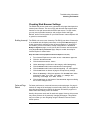
After communication has been established, you can set any required
configuration parameters for the E5810 by using the E5810 Web access.
46
Chapter 2
Installing the E5810A
Configuring the E5810A on a Local Network
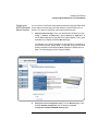
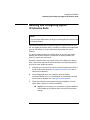
Configuring the
You can check or set E5810 configuration parameters using the E5810 Web
E5810 for Enterprise access that is accessed from your Web browser (Internet Explorer 6.0 or
Network Operation greater). The steps to set E5810 configuration parameters are:
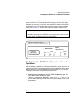
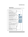
1
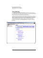
Display the Welcome Page. From your Web browser address line, type
‘http://<E5810 IP Address>’, where <E5810 IP Address> is
the IP address displayed on the E5810 front panel display. Then, press
the Enter key to display the E5810 Welcome page.
For example, if the default IP address of 169.254.58.10 is displayed on
the E5810 front panel, typing http://169.254.58.10 on your Web
browser address line and pressing Enter displays the E5810 Welcome
page. The following figure shows a typical display.
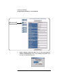
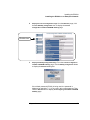
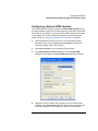
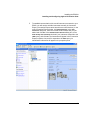
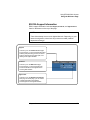
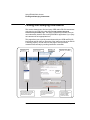
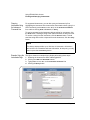
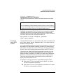
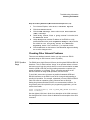
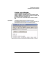
2
Display the Current Configuration Page. From the Welcome page, click
the View & Modify Configuration icon to display the Current
Configuration of E5810 LAN/GPIB Gateway page
Chapter 2
47
Installing the E5810A
Configuring the E5810A on a Local Network
Click this icon
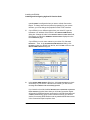
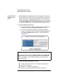
3
48
Display the Modify Configuration Page. From the Current Configuration
of E5810 LAN/GPIB Gateway page, click the Modify Configuration button
to display the Password dialog box.
Chapter 2
Installing the E5810A
Configuring the E5810A on a Local Network
If the default password (E5810) is being used, the password is
displayed as asterisks (*****). If not, type in the current password. Then,
click the Submit button to display the Configuring Your E5810 LAN/GPIB
Gateway page.
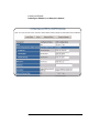
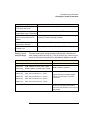
4
Set E5810 for Enterprise Network Operation. To properly set E5810
configuration parameters for eventual use on an Enterprise network,
you may need to enter the following network values, as provided to you
by your System Administrator, on the Configuring your E5810 LAN/GPIB
Gateway page.
Chapter 2
49
Installing the E5810A
Configuring the E5810A on a Local Network
IP Address Assignment
Enterprise Network Supports DHCP
Enterprise Network Does Not Support DHCP
No action required. The E5810 automatically
receives an IP address from the network
DHCP Server.
Click DHCP OFF and enter the values
provided by the System Administrator for
IP Address, Subnet Mask, and Default
Gateway IP Address.
Hostname
Enterprise Network Supports DNS
Enterprise Network Does Not Support DNS
If the network supports dynamic DNS, enter
the Hostname provided by the System
Administrator. Then, you can access the
E5810 from your Web browser by using the
Hostname.
No action required. Hostnames are not
supported. Use only the IP address when
communicating with the E5810.
If the network supports DNS, enter the DNS
Server IP Address provided by the System
Administrator.
Universal Plug and Play (UPnP)
UPnP Enabled is Allowed on Enterprise
Network
UPnP Enabled is Not Allowed on Enterprise
Network or You Do Not Want the E5810 to be
Displayed in My Network Places
No action is required for the E5810. However,
if you want to see the E5810 in My Network
Places, you may need to enable UPnP on
your computer’s Operating System.
Set Universal Plug and Play to OFF.
50
Chapter 2
Installing the E5810A
Configuring the E5810A on a Local Network
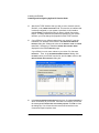
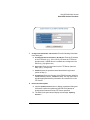
Example:
Configuring the
E5810
This example shows one way to set various E5810 parameters on the
Configuring your E5810 LAN/GPIB Gateway page, assuming the Enterprise
network to which the E5810 will be connected does not support DHCP or
DNS. Since the network does not support DNS, a Hostname cannot be used
for this E5810. In addition, it is assumed the network does not allow UPnP,
so Universal Plug and Play is set to OFF.
2. Click the Save button
to save changes
3. Click Reboot E5810 to reboot
and make changes effective
1. Set DHCP OFF
Enter New IP Address
Enter New Subnet Mask Value
Enter New Default Gateway IP Address
Leave DNS Server Address Blank
Leave Hostname Blank
Set Universal Plug and Play to OFF.
Configuring the
E5810 for Local
Network Operation
If you plan to install your E5810 on a Local network, use the Configuring
your E5810 LAN/GPIB Gateway page to set the parameters applicable to your
Local network.
Where to go Next
To Install the E5810 on an Enterprise Network. Disconnect the E5810
from the Local network and go to “Installing the E5810A on an
Enterprise Network”.
To Use the E5810 on a Local Network. Leave the E5810 connected to
the Local network and go to “Verifying Instrument Communication”.
Chapter 2
51
Installing the E5810A
Installing the E5810A on an Enterprise Network
Installing the E5810A on an Enterprise
Network
This step gives guidelines to install an E5810 on an Enterprise network.
NOTE
If your Enterprise network does not support Dynamic Host Configuration
Protocol (DHCP), you must first configure your E5810 on a Local network
as shown in “Configuring the E5810A on a Local Network” and then
return to this step to install the E5810 on the Enterprise network.
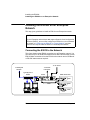
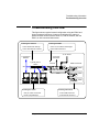
Connecting the E5810 to the Network
This figure shows typical E5810 connections to an Enterprise network. You
can connect up to 14 GPIB instruments and one RS-232 instrument to each
E5810. Make connections from the E5810 to the network and to GPIB and/
or RS-232 instruments as required.
To AC Power
To Enterprise
Network
To RS-232
Instrument
Typically Hub or
Switch
GPIB Instruments
E5810A
OR
POWER
Tx
LAN
GP IB
RS232
Ln
!
GPIB
LAN
GPIB
GPIB
GPIB
52
Chapter 2
Installing the E5810A
Installing the E5810A on an Enterprise Network
After connecting the E5810 to the Enterprise network, plug the E5810 AC
power cord into an AC outlet and observe the power-on sequence. When
the power-on sequence is complete, the assigned IP address of the E5810
is displayed on the second line of the front panel display. A typical display
follows. See Chapter 1, “E5810A Description” for power-on sequences.
NOTE
The Mains disconnect for the E5810 is to unplug the AC power cord from
the AC outlet. The E5810 has no AC Power switch.
IP Address and Hostname Displayed
Display shows IP address (and Hostname, if known)
E5810A
LAN/GPIB Gateway
Hostname
169.254.58.10
Power
Activity
LAN GPIB RS232
Fault
Preset
Configuring the E5810A for Enterprise Network
Operation
After the E5810 is installed on the Enterprise network, you can check or set
(as required) E5810 configuration parameters using the E5810 Web access
that is accessed from your Web browser (Internet Explorer 6.0 or greater).
The steps to set E5810 configuration parameters are:
1
Display the Welcome Page. To display the E5810 Welcome page, from
your Web browser address line, type
‘http://<E5810 IP Address>’, where <E5810 IP Address> is
the IP address displayed on the E5810 front panel display. Then, press
the Enter key.
Chapter 2
53
Installing the E5810A
Installing the E5810A on an Enterprise Network
For example, if the default IP address of 169.254.58.10 is displayed on
the E5810 front panel, typing http://169.254.58.10 on your Web
browser address line and pressing Enter displays the E5810 Welcome
page. The following figure shows a typical display.
54
Chapter 2
Installing the E5810A
Installing the E5810A on an Enterprise Network
2
Display the Current Configuration Page. from the Welcome page, click
the View & Modify Configuration icon to display the Current
Configuration of E5810 LAN/GPIB Gateway page
Click this icon
3
Display the Modify Configuration Page. From the Current Configuration
of E5810 LAN/GPIB Gateway page, click the Modify Configuration button
to display the Password dialog box.
If the default password (E5810) is being used, the password is
displayed as asterisks (*****). If not, type in the current password. Then,
click the Submit button to display the Configuring Your E5810 LAN/GPIB
Gateway page.
Chapter 2
55
Installing the E5810A
Installing the E5810A on an Enterprise Network
56
Chapter 2
Installing the E5810A
Installing the E5810A on an Enterprise Network
4
Set E5810 for DHCP Enterprise Network Operation. For an Enterprise
network that supports DHCP, the only values you may need to set are
the Hostname and Universal Plug and Play (UPnP) settings, as
provided to you by your System Administrator, on the Configuring your
E5810 LAN/GPIB Gateway page.
Hostname
Enterprise Network Supports DNS
Enterprise Network Does Not Support DNS
If the network supports dynamic DNS,
enter the Hostname provided by the System
Administrator. Then, you can access the
E5810 from your Web browser by using the
Hostname.
No action required. Hostnames are not
supported. Use only the IP address when
communicating with the E5810.
If the network supports DNS, enter the DNS
Server IP Address provided by the System
Administrator.
Universal Plug and Play (UPnP)
UPnP Enabled is Allowed on Enterprise
Network
UPnP Enabled is Not Allowed on Enterprise
Network or You Do Not Want the E5810 to be
Displayed in My Network Places
No action is required for the E5810. However,
if you want to see the E5810 in My Network
Places, you may need to enable
UPnP on your computer’s Operating System.
Set Universal Plug and Play to OFF.
Where to Go Next
Go to “Verifying Instrument Communication”
Chapter 2
57
Installing the E5810A
Verifying Instrument Communication
Verifying Instrument Communication
The last step in installing and configuring the E5810 is to verify
communication from your PC to up to 14 connected GPIB instruments and/
or one RS-232 instrument via the E5810 Web access. See Chapter 3,
“Using E5810A Web Access” for details.
NOTE
Over the Web, you can interact with instruments via your Web browser.
To program instruments via the E5810 using an application language
such as C or Visual Basic, you must first install and configure the
Agilent IO Libraries Suite as shown in “Installing and Configuring Agilent
IO Libraries Suite” on page 61.
Open the Instrument Page
You can verify instrument communication using the Find and Control
Instruments Connected to your E5810 page of the E5810 Web access.
NOTE
Before opening the Find and Control Instruments Connected to your E5810
page, be sure all connected instruments are plugged in and turned on.
On the address line of your Web browser type http://<E5810 IP
Address> (where <E5810 IP Address> is the IP address of the E5810
shown on the front panel display). Then, press Enter to display the Welcome
page.
From the Welcome page, click the Find&Query Instruments icon to display the
Password dialog box. If the default password is being used, the Password
dialog box shows asterisks (*****). If not, type in the E5810 password. Click
the Submit button to display the Find and Control Instruments Connected to
your E5810 page.
58
Chapter 2
Installing the E5810A
Verifying Instrument Communication
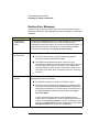
Instrument Page Functions
From the Find and Control Instruments Connected to your E5810 page, you
can check instrument communication, send command/queries, and do other
functions.
Checking Instrument To check instrument communication, first select (highlight) the instrument to
Communication
be addressed by clicking the SICL Address in the Instruments Connected
column. Then, depending on the instrument selected, you can use button
functions (device clear, *IDN?, etc.) to communicate with the instrument.
Sending
You can also send instrument-specific commands to applicable instruments
Commands/Queries using the Instrument Command line and then clicking Send, Receive, or
Query. In addition, you can clear the display on the screen by clicking the
Clear History button, set the timeout value (in seconds) by typing in the
desired value in the Timeout (sec) dialog box, and clear all pending
operations on instruments connected to the E5810 by clicking the Clear
Pending Operations button.
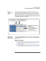
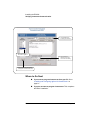
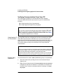
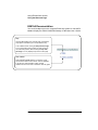
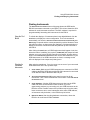
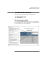
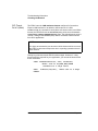
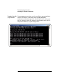
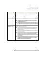
Example: Querying For example, the figure on the next page shows one way to identify and
a DC Voltage Value query the DC voltage value of a DMM instrument at SICL address gpib0,22.
See Chapter 3, “Using E5810A Web Access” for details
Chapter 2
59
Installing the E5810A
Verifying Instrument Communication
3. Click the *IDN? button
to identify the instrument
2. Select Instrument at
SICL Address gpib0,22
4. Type command on
Instrument Command
line and then click Query
1. Click the Find button (as required)
to display all connected instruments
Where to Go Next
60
If you want to program instruments from your PC. Go to
“Installing and Configuring Agilent IO Libraries Suite” on
page 61.
If you do not want to program instruments. This completes
the E5810 installation.
Chapter 2
Installing the E5810A
Installing and Configuring Agilent IO Libraries Suite
Installing and Configuring Agilent
IO Libraries Suite
NOTE
You must have Administrator privileges to install Agilent IO Libraries Suite
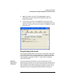
Connection Expert.
This section describes how to install the Agilent IO Libraries Suite on your
PC. The Agilent IO Libraries Suite is a collection of libraries and utilities that
gives you the ability to use your instruments from instrument control
software.
You should install the Agilent IO Libraries Suite as your first step before
installing the hardware because it installs the necessary software and
drivers to control your instruments.
If possible, always use the most recent version of the Agilent IO Libraries
Suite. This version supports the newest interfaces and operating systems,
and has the most advanced features.
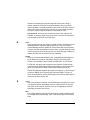
1
Verify that your PC meets the minimum system requirements. Refer to
the IO Libraries Web page at www.agilent.com/find/iosuite or the IO
Libraries Suite Readme.
2
Close all applications on your computer. Insert the Agilent
Automation-Ready CD in your CD-ROM drive or download and install
the IO Libraries software from www.agilent.com/find/iosuite.
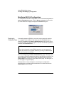
3
Follow the instructions as prompted during the installation. You can
select either a Typical or a Custom installation:
Chapter 2
Typical - In most cases, you can select the Typical installation
which installs the IO Libraries Suite using the recommended
settings.
61
Installing the E5810A
Installing and Configuring Agilent IO Libraries Suite
4
62
Custom - Select the Custom installation to:
a
Install the IO Libraries Suite in another directory
(for 32- bit operating systems only).
b
Save disk space by not installing interface manuals.
c
Use Agilent 32- bit VISA with another vendor's VISA on
the same PC in side-by-side mode. Details on
side-by-side mode are available at
www.agilent.com/find/side-by-side-install or in the IO
Libraries Suite help.
After the IO Libraries suite is successfully installed, you will see the IO
icon on the Windows taskbar notification area.
Chapter 2
Installing the E5810A
Installing and Configuring Agilent IO Libraries Suite
Configuring a Remote GPIB Interface
This section shows the steps to configure a remote GPIB interface, which
is a logical interface on the client PC that supports communication with GPIB
instruments on your E5810. If you do not have GPIB instruments connected
to your E5810, but do have an RS-232 instrument connected, skip this
section and go to “Configuring a Remote Serial Interface” on page 65.
1
Click the Agilent IO Control icon (IO icon on the Windows taskbar
notification area) and click Agilent Connection Expert to display the
Connection Expert utility’s main window.
2
Click Add an interface on the Connection Expert toolbar.
3
In the Manually Add an Interface dialog box, select Remote GPIB
interface and click Add. The Remote GPIB Interface dialog will appear.
4
Specify the TCPIP interface that you wish to use to host this remote
interface, in the TCPIP interface ID: field. This must be an interface that
is already configured on your system; by default, a LAN interface
Chapter 2
63
Installing the E5810A
Installing and Configuring Agilent IO Libraries Suite
named TCPIP0 is configured when you start or refresh Connection
Expert. To change timeouts and protocol properties for your remote
interface, you must change the properties of this TCPIP interface.
5
If your E5810 is on a different subnet from your client PC, type the
hostname or IP address of the E5810 in the Remote GPIB interface
dialog box. Change the value in the Interface name on remote host: field,
if necessary, to match the GPIB SICL Interface Name displayed on the
E5810 Welcome page.
If your E5810 is on the same subnet as your client PC, click Find
Interfaces.... Then, in the Find Remote GPIB Interfaces dialog, click
Find Now, select your E5810 from the list, and click OK to return to the
Remote GPIB interface dialog box.
6
In the Remote GPIB interface dialog box, click Test connection to check
connectivity to your E5810. If the test is successful, you will see the
message The interface was successfully opened.
If you leave the check box labeled Auto-discover instruments connected
to this interface checked, then when you click OK, Connection Expert
will search for GPIB instruments connected to your E5810 and will send
a *IDN? (identification) query to each instrument found. You will then
see the new remote GPIB interface and any attached GPIB instruments
in the Connection Expert’s explorer view.
64
Chapter 2
Installing the E5810A
Installing and Configuring Agilent IO Libraries Suite
Configuring a Remote Serial Interface
This section shows the steps to configure a remote serial interface, which
is a logical interface on the client PC that supports communication with
RS-232 instruments on your E5810. If you do not have an RS-232
instrument connected to your E5810, skip this section and go to the next
step, “Verifying Communication From Your PC” on page 68.
1
Click the Agilent IO Control icon (IO icon on the Windows taskbar
notification area) and click Agilent Connection Expert to display the
Connection Expert utility’s main window.
2
Click Add Interface on the Connection Expert toolbar.
3
In the Manually Add an Interface dialog box, select Remote RS-232 serial
interface and click Add. The Remote RS-232 Serial Interface dialog will
appear.
Chapter 2
65
Installing the E5810A
Installing and Configuring Agilent IO Libraries Suite
4
Specify the TCPIP interface that you wish to use to host this remote
interface, in the TCPIP interface ID: field. This must be an interface that
is already configured on your system; by default, a LAN interface
named TCPIP0 is configured when you start or refresh Connection
Expert. To change timeouts and protocol properties for your remote
interface, you must change the properties of this TCPIP interface.
5
If your E5810 is on a different subnet from your client PC, type the
hostname or IP address of the E5810 in the Remote RS-232 Serial
Interface dialog box. Change the value in the Interface name on remote
host: field, if necessary, to match the RS-232 SICL Interface Name
displayed on the E5810 Welcome page.
If your E5810 is on the same subnet as your client PC, click Find
Interfaces.... Then, in the Find Remote ASRL Interfaces dialog, click
Find Now, select your E5810 from the list, and click OK to return to the
Remote RS-232 Serial Interface dialog box.
6
66
In the Remote RS-232 Serial Interface dialog box, click Test connection to
check connectivity to your E5810. If the test is successful, you will see
the message The interface was successfully opened. Click OK to close
the dialog box. You will see the new remote serial interface in the
Connection Expert’s explorer view.
Chapter 2
Installing the E5810A
Installing and Configuring Agilent IO Libraries Suite
7
To establish communication with a serial instrument connected to your
E5810, you will need to add this instrument manually in Connection
Expert. (Connection Expert cannot auto-discover serial devices.) In the
main Connection Expert window, click Add Instrument. In the Add
Instrument dialog box, select the remote serial interface that you just
added and click OK. In the RS-232 Serial Instrument dialog box, leave
Auto-identify this instrument checked if your instrument responds to the
*IDN? query, and click OK. The instrument will appear in the Connection
Expert’s explorer view, and if it responds to the *IDN? query, its
identification information will appear in the properties pane.
Chapter 2
67
Installing the E5810A
Installing and Configuring Agilent IO Libraries Suite
Verifying Communication From Your PC
This section gives guidelines to communicate with and to program
connected GPIB and RS-232 instruments from your PC via the E5810,
including:
Using Interactive IO for Communication
Using Supported Programming Languages
NOTE
You can also communicate with (but not program) installed GPIB and/or
RS-232 instruments using the E5810 Web access, whether or not you
have installed and configured the Agilent IO Libraries Suite. See Chapter
3, “Using E5810A Web Access” for details.
Using Interactive IO After the E5810 has been configured and you have connected your GPIB
for Communication and/or RS-232 instruments to the E5810, you can verify communication
between your PC and the instruments by using the Interactive IO utility or by
using VISA or SICL commands with supported programming languages.
This section shows one way to use Interactive IO to verify instrument
communication.
NOTE
Once your remote interface(s) and instrument(s) have been configured in
Connection Expert, if you can see them in the Connection Expert explorer
and see their IDN string information in the detail pane then
communication has been verified. Interactive IO allows you to manually
verify communication and send specific commands to your instrument.
Example: Using
Interactive IO
To use Interactive IO to send a *IDN? (identification) query to an instrument:
1
Select the instrument by clicking its icon in the Connection Expert
explorer view.
2
Right-click the instrument and click Send Commands To This Instrument
to display the Interactive IO window. For information on Interactive IO,
including a list of common commands and their meanings, click Help |
Help Topics.
68
Chapter 2
Installing the E5810A
Installing and Configuring Agilent IO Libraries Suite
3
*IDN? is the default command. Click Send & Read to send the
identification query to the instrument and display its reply in the
Interactive IO window.
4
To send other commands, click Commands> to select from a list of
common commands, or type a command into the Command: field. If you
experience timeout errors for some commands, click Options to change
the timeout value.
Programming Instruments
You can program GPIB and RS-232 instruments via the E5810 using VISA,
VISA COM, or Agilent SICL to send instrument commands such as SCPI.
You can program in various languages/applications, including Visual Studio
.NET languages, Visual Basic, Visual C++, Agilent VEE, and National
Instruments LabVIEW.
Applicable
Programming
Documents
For general programming guidelines, see the documentation for your
programming environment. You can also find programming examples using
various I/O libraries and instrument drivers in the instrument User’s Guide.
After the E5810 is successfully installed and configured, it should act as a
transparent interface for programming GPIB and RS-232 instruments.
Chapter 2
69
Installing the E5810A
Installing and Configuring Agilent IO Libraries Suite
For information on programming using Agilent VISA, see the Agilent VISA
User’s Guide. Also see the Agilent Connectivity Guide and Agilent
IO Libraries Suite Online Help for further information and guidelines on
programming with the Agilent IO Libraries.
Addressing
Instruments using
VISA and Remote
IO Client
Once you have created a remote GPIB or remote serial interface in
Connection Expert, you can use ordinary GPIB or serial addressing in your
VISA or VISA COM programs to address instruments on these interfaces.
The Remote IO Client software maps TCPIP address requests into
appropriate interface type (GPIB or ASRL) addresses; thus the IP address
and hostname of the E5810 do not appear in the instrument address. This
makes it possible to use existing programs written for GPIB or ASRL without
having to modify code.
See “Configuring a Remote Serial Interface” on page 65 to configure a
remote GPIB or remote serial interface. VISA programs can then use
addresses such as GPIB0::22::INSTR (for GPIB) or ASRL1::INSTR (for
RS-232). Use these addresses in your viOpen() call as follows:
viOpen (...”GPIB0::22::INSTR”...)
viOpen (...”ASRL1::INSTR”...)
Addressing
Instruments using
VISA and TCPIP
Interface
Although remote GPIB and remote serial interfaces are the most convenient
way to configure and program instruments on your E5810, you may choose
not to use them. For example, if you are using another vendor’s I/O software
rather than the Agilent IO Libraries Suite, your I/O software probably does
not support remote interface addressing. (At the time of this writing, only
Agilent software supports remote interface types.)
If you are not using remote interfaces, you will address your instruments as
TCPIP resources in VISA. These addresses include the IP address or
hostname of the E5810 as well as the SICL address of the device on the
E5810.
Use these addresses in your viOpen() call as follows. These examples
assume that the VISA interface ID of your TCPIP interface is “TCPIP0”. (You
can specify this interface ID with the Connection Expert utility; “TCPIP0” is
the default VISA ID for the default TCPIP interface.)
viOpen (...”TCPIP0::my_IP_address::gpib0,22::INSTR”...)
viOpen (...”TCPIP0::my_IP_address::COM1,488::INSTR”...)
70
Chapter 2
Installing the E5810A
Installing and Configuring Agilent IO Libraries Suite
Addressing
Instruments with
SICL
SICL addresses include the IP address or hostname of your E5810 as well
as the SICL address of the device on the E5810, and optionally the protocol
to be used. Some example addresses for SICL programs follow. These
examples assume that the SICL interface ID of your TCPIP interface is “lan”.
(You can specify this interface ID with the Connection Expert utility; “lan” is
the default SICL ID for the default TCPIP0 interface.)
lan[my_IP_Address]:gpib0,22
lan;vxi-11[my_IP_Address]:gpib0,22
lan[my_IP_Address]:COM1,488
lan;sicl-lan[my_IP_Address]:gpib0,11
NOTE
At the time of this writing, National Instruments I/O software does not
support the SICL-LAN protocol, but only the VXI-11 protocol. Because
RS-232 instruments are only supported by SICL-LAN and not VXI-11, you
cannot use National Instruments I/O software to program an RS-232
instrument on your E5810.
Chapter 2
71
Installing the E5810A
Installing and Configuring Agilent IO Libraries Suite
Notes:
72
Chapter 2
3
Using E5810A Web Access
Using E5810A Web Access
This chapter gives guidelines on how to use E5810A Web access, including:
74
Opening Your Web Browser for E5810A Web Access
Using the Welcome Page
Viewing and Modifying Current Configuration
Finding and Querying Instruments
Other Web Access Functions
Chapter 3
Using E5810A Web Access
Opening Your Web Browser for E5810A Web Access
Opening Your Web Browser for E5810A Web
Access
Since the E5810 is Web-enabled, you can access and communicate with the
E5810 using your Web browser (Internet Explorer 6.0 or greater).
To display the E5810 Welcome page, open your Web browser and type
http://<E5810 IP Address> or http://<E5810 Hostname>
on the address line, where <E5810 IP Address> is the IP address of the
E5810 and <E5810 hostname> is the Hostname of the E5810 (if known).
Then, press the Enter key.
For example, assume the E5810 IP Address is 169.254.58.10 (the default
static IP address). Typing http://169.254.58.10 and pressing Enter
displays the E5810 Welcome page. A typical Welcome page display (with a
non-default IP address shown) follows. The Welcome page is the home
page. The banner and the Navigation Bar (Welcome Page, etc.) are a fixed
frame for each page. The text within each page scrolls (as necessary) to
display desired information.
Chapter 3
75
Using E5810A Web Access
Using the Welcome Page
Using the Welcome Page
This section shows the features of the E5810 Welcome page, including the
following items. A typical Welcome page display follows.
Navigation Bar
E5810A Current Settings
E5810A Support Information Banner
E5810A Documentation Links
E5810 Support
Information
E5810 Current
Settings
Navigation
Bar
E5810 Documentation
76
Chapter 3
Using E5810A Web Access
Using the Welcome Page
Navigation Bar
Clicking the applicable icon on the Navigation Bar on the left side of the page
allows you to take the actions shown in the following figure.
Welcome Page
Displays the Welcome page.
View & Modify Configuration
Displays the Current Configuration of E5810
LAN/GPIB Gateway page. From this page, you
can view current E5810 configuration parameters.
Clicking the Modify Configuration button on this
page displays the Configuring your E5810
LAN/GPIB Gateway page, from which you can
view and modify E5810 configuration.
Find & Query Instruments
First displays the Password dialog box. After
you enter the E5810 password and click Submit,
the Find and Control Instruments Connected to
your E5810 page is displayed.
From this page, you can interact with GPIB and
RS-232 instruments connected to the E5810.
Session Status
Displays the E5810 LAN/GPIB Gateway Status
page. From this page, you can view the current
Firmware Revision, LAN Speed at Reboot, Time
Since Reboot, and Connection Status.
Print Page
Prints the currently displayed page on your
default printer.
Help with this Page
Displays the Web page help for items on the
currently displayed page.
Chapter 3
77
Using E5810A Web Access
Using the Welcome Page
E5810A Current Settings
The Current Settings part of the Welcome page displays some of the current
settings for the E5810. A typical display follows. See “E5810 Configuration
Parameter Descriptions” in this chapter for detailed descriptions.
Ethernet (MAC) Address
A unique address assigned by the manufacturer
for each Internet device. The Ethernet address
is on a label on the underside of the E5810.
Hostname
Internet domain name for the E5810 that may
be used to communicate with the E5810. The
Hostname is not a required configuration value.
IP Address
The E5810 IP Address. An IP address is a
32-bit numeric address expressed as four
numbers separated by periods (e.g.,
152.160.10.240).
GPIB SICL Interface Name
Each GPIB interface used by Agilent VISA
or SICL must have a SICL Interface Name.
For VXI-11 protocol, use "gpib0".
RS-232 SICL Interface Name
"COM1" is the default value. Client SICL
applications will use full SICL name of
"COM1,488".
Firmware Revision
Current firmware revision on this E5810.
See “Updating E5810 Firmware” for
information on upgrading E5810 firmware.
Serial Number
Unique serial number for this E5810, located
on a label on the underside of the E5810.
78
Chapter 3
Using E5810A Web Access
Using the Welcome Page
E5810A Support Information
E5810 support information includes Support, Products, and Agilent Site as
listed on the banner on the top of the page.
NOTE
These links attempt to access the Agilent Web site. Depending on your
network configuration, these links may not be accessible (networkdependent message).
Support
Connects you to the Contact Us Web page.
From this page, you can find information about
selecting and purchasing products, technical
support, equipment service and repair, and
training on the Agilent Website.
Products
Connects you to the E5810 Web page.
From this page, you can find product and
service information for the Agilent E5810
on the Agilent Website.
Agilent Site
Connects you to the Agilent Technologies
Web page. From this page, you can access
complete information about Agilent
Technologies from the Agilent Website.
Chapter 3
79
Using E5810A Web Access
Using the Welcome Page
E5810A Documentation
You can click Help to access a complete E5810 help system or click User’s
Guide to display the E5810 LAN/GPIB Gateway for Windows User’s Guide.
Help
Clicking Help displays the contents page of the E5810
help system and allows you to access E5810 help.
This is different than clicking the Help with this Page
icon in that clicking Help provides you with access to
the entire Help system, while clicking the Help with
this Page icon only displays help for the active page.
User's Guide
Clicking User’s Guide displays an electronic (.pdf)
version of this E5810 User’s Guide. This link attempts
to access the Agilent website. Adobe Acrobat
Reader Version 3.0 or later is needed to view the guide.
80
Chapter 3
Using E5810A Web Access
Viewing and Modifying Configuration
Viewing and Modifying Configuration
This section shows how to view and modify (as required) the current
configuration of the E5810 using the Current Configuration of E5810
LAN/GPIB Gateway and the Configuring your E5810 LAN/GPIB Gateway page.
Viewing E5810A Configuration
To begin modifying the E5810 current configuration, click the View & Modify
Configuration icon to display the Current Configuration of E5810 LAN/GPIB
Gateway page. A typical display of the page follows.
Chapter 3
81
Using E5810A Web Access
Viewing and Modifying Configuration
Modifying E5810A Configuration
To modify the current E5810 configuration, from the Current Configuration of
E5810 LAN/GPIB Gateway page, click the Modify Configuration button at the
top or the bottom of the page to display the Password dialog box.
Displaying the
If the default password (E5810) is set as the current password, asterisks
Configuration Page (*****) appear in the window. In this case, just click the Submit button to
display the Configuring your E5810 LAN/GPIB Gateway page (see the figure
on the next page). If no asterisks appear, enter the current E5810 password
and then click the Submit button.
NOTE
If you do not know the current E5810 password, you can temporarily
reset the password to the default (E5810) by pressing the Preset button
on the front panel of the E5810.
When the Configuring your E5810 LAN/GPIB Gateway page is displayed, you
can configure desired parameters by typing or selecting the new value in the
Edit Configuration column and then clicking the Save button and then the
Reboot E5810 button at the top or the bottom of the page. See the figure on
the next page for a typical display.
Although there are a few exceptions, most changes to configuration
parameters are not effective until the Save button is clicked and then the
Reboot E5810 button is clicked.
82
Chapter 3
Using E5810A Web Access
Viewing and Modifying Configuration
Chapter 3
83
Using E5810A Web Access
Viewing and Modifying Configuration
E5810 Configuration An alphabetical listing of E5810 configuration parameter descriptions and
Parameter
applicable default (factory-set) values follows. The E5810 uses the default
Descriptions
configuration values until you change any value and save/reboot. The
E5810 also uses the default values when you press and hold down the
Preset button for >10 seconds.
Parameter
[Default]
Description
Default Gateway
[0.0.0.0]
This value is the IP address of the default subnet gateway that allows the
E5810 to communicate with systems that are not on the local subnet.
This is the default subnet gateway where packets are sent which are
destined for a device not on the local subnet, as determined by the
subnet mask setting. Only one default subnet gateway can be configured.
A value of 0.0.0.0 indicates that no subnetting is to be done.
Description
[Factory-Set]
The default description consists of “E5810 LAN/GPIB Gateway” followed
by the Ethernet (MAC) address. The Ethernet address is printed on a
label on the underside of the E5810.
A typical description is: Agilent E5810 00-30-D3-05-00-23, where
00-30-D3-05-00-23 is the Ethernet address. The description is the “UPnP
Friendly Name” of the E5810 that will automatically be displayed on
UPnP (Universal Plug and Play) enabled LAN hosts.
When the E5810 is connected to the LAN, it broadcasts its presence to
the network if UPnP is enabled. UPnP clients will then see this E5810 in
My Network Places, listed by this Description. A Friendly Name can be up
to 39 characters, including spaces.
Domain Name
Server (DNS)
[0.0.0.0]
A DNS Server is an Internet service that translates domain names into IP
addresses and vice-versa. Every time you use a domain name, a DNS
Server must translate the name into the corresponding IP address.
For example, the domain name www.example.com might translate to
198.105.232.4. The DNS system has its own network. If one DNS Server
does not know how to translate a particular domain name, it asks another
DNS Server, etc. until the correct IP address is returned, if available.
84
Chapter 3
Using E5810A Web Access
Viewing and Modifying Configuration
Parameter
[Default]
Domain Name
Server (DNS)
(cont)
[0.0.0.0]
Description
A DNS Server is an Internet service that translates domain names into IP
addresses. Every time you use a domain name, a DNS server must
translate the name into the corresponding IP address. For example, the
domain name www.example.com might translate to 198.105.232.4.
The DNS system is distributed. If one DNS server does not know how to
translate a particular domain name, it asks another DNS server, etc. until
the correct IP address is returned. If DHCP is used, a DHCP Server may
provide a DNS Server IP address to the E5810 (this is transparent to the
user). If the user configures a DNS Server, the E5810 will try to use that
Server first.
This parameter shows the IP address of the domain name Server. More
than one address may be listed on the Current Configuration of the E5810
LAN/GPIB Gateway page. Up to two of these values may have been
returned by the DHCP Server during startup. Only one static value can be
input on the Configuring your E5810 LAN/GPIB Gateway page.
The DNS Server provides a Hostname, given an IP Address, for a LAN
device based on entries in its DNS lookup table. If DHCP is OFF and you
do not specify a DNS Server or if Dynamic DNS is not available on your
enterprise LAN and your IP Address is not in the DNS lookup table on the
DNS Server, your Hostname will be unknown and you must address the
E5810 only by its IP Address. The Hostname is not a required entry.
Dynamic Host
Configuration
Protocol (DHCP)
[ON]
DHCP is a protocol for assigning dynamic IP addresses to devices on a
network. DHCP supports a mix of static and dynamic IP addresses. The
two options for DHCP are ON (default) or OFF.
DHCP ON (Default): If DHCP is ON (the factory default setting), the E5810
will try to obtain an IP address from a DHCP Server. If this fails, the
E5810 will use its static IP address. If DHCP is ON and a DHCP Server is
found, the manually configured IP Address, Subnet Mask, and Default
Gateway parameters are not used by the E5810 during startup and thus
are not required settings.
Chapter 3
85
Using E5810A Web Access
Viewing and Modifying Configuration
Parameter
[Default]
Description
Dynamic Host
Configuration
Protocol (DHCP)
[ON]
(cont’d)
DHCP OFF: If DHCP is OFF or unavailable, during startup the E5810 will
use the static IP address that may be input in the Configuring your E5810
LAN/GPIB Gateway page. In this case, the values for the IP Address,
Subnet Mask, and Default Gateway shown in the Configured Value column
of the page will be used during startup.
E5810 Serial
Number
[Factory-Set]
The individual Serial Number assigned at the factory for each E5810. The
Serial Number is printed on a label on the underside of the E5810 and
has the form US12345678.
Ethernet (MAC)
Address
[Factory-Set]
This is the Media Access Control Address, also known as the link-level
address, the Ethernet (station) Address, the LANIC ID and Hardware
Address. This is a unique 48-bit address assigned by the manufacturer
for each Ethernet device. The address is usually 12 hexadecimal
characters, with colon or dash separators between every two characters,
such as “00:30:D3:05:00:23” or “00-30-D3-05-00-23”. The Ethernet
address is printed on a label on the underside of the E5810.
GPIB Address
[21]
This value configures the GPIB bus address of the E5810. This address
is used when transfers are made on the GPIB bus. A SICL client
application can change this value by using the SICL function
IGPIBBUSADDR. The GPIB address value can be any number 0 through
30.
GPIB Logical Unit
[7]
This value is the interface logical unit (LU) number of the GPIB interface
in the E5810. It may be used in an Agilent SICL client application’s iopen
statement to uniquely identify the GPIB interface in the E5810. The GPIB
logical unit value can be any number 1 through 255.
GPIB SICL Interface
Name
[gpib0]
This value is the symbolic name of the GPIB interface in the E5810. It is
used in a SICL client application’s iopen operation to symbolically
reference the GPIB interface in the E5810. The maximum length of the
GPIB interface name is 15 characters. If VXI-11 (TCP/IP Instrument
Protocol) is used, the name must be gpib<n>. The names “hpib” or
“hpib7” may be used to more easily support legacy programs, if only
SICL/LAN protocols will be used.
86
Chapter 3
Using E5810A Web Access
Viewing and Modifying Configuration
Parameter
[Default]
Hostname
[None]
Description
This value configures the internet domain name for the E5810.
Hostnames are useful when IP addresses are being assigned by a DHCP
Server, since the Hostname will not change despite DHCP Server
changes and device IP address changes.
If a Hostname is entered, the E5810 will try to register this name when it
boots. The E5810 can only register the Hostname if the network has
Dynamic DNS. If the network does not have Dynamic DNS, this value is
not used. Since you can always use the IP Address or the name (possibly
supplied by another name Server), the Hostname is not a required
configuration value.
You may enter up to 35 characters for the Hostname. The Hostname
must start with a letter and consists of upper and lower case letters and
digits and dashes. There is no default Hostname. If a Hostname is
displayed on the Welcome page, it is a valid Hostname, since one was
found on the network through DNS.
I/O Timeout
[120 sec]
This value sets the Server I/O timeout in seconds. It configures the E5810
to use an I/O timeout of the specified amount of seconds if the client
requests a timeout of infinity. If 0 is specified for this value and the client
requests an infinite timeout, the E5810 will use a timeout of infinity as
requested.
Setting the I/O timeout to 0 is NOT recommended, as this can result in the
E5810 waiting indefinitely for an I/O operation and effectively “hang” the
E5810.
This timeout value may be used to ensure that the E5810 does not wait
indefinitely for an I/O operation. It also allows the E5810 to detect certain
network events (such as when a client connection is dropped) that may
otherwise go undetected. If the E5810 detects such a condition, it will
release any resources, such as locks, associated with the client.
This value also allows the E5810 to detect certain network events, such
as when a client connection is dropped. If the E5810 detects such a
condition, it will release any resources, such as locks, associated with the
client. The factory default setting is 120 sec.
Chapter 3
87
Using E5810A Web Access
Viewing and Modifying Configuration
Parameter
[Default]
IP Address
[169.254.58.10]
Description
This value is the Internet Protocol (IP) address of the E5810. The IP
address is a required value and is used for all IP and TCP/IP
communications with the E5810. The IP address is represented in dotted
decimal notation (for example, 154.140.222.201). This number is assigned
by the System Administrator. The E5810 has a default static IP address
of 169.254.58.10.
LAN traffic to the E5810 will be routed by the IP Address or by using a
Hostname that may be provided by a DNS name Server which is mapped
to this IP Address. The current E5810 IP Address may have been
established in one of two ways:
The IP address was provided by a DHCP Server during startup
(dynamic IP address).
The IP address shown on the Current Configuration of the E5810
LAN/GPIB Gateway page was used. This was set at the factory to
169.254.58.10. If DHCP will not be used, the IP address should be
set for your network.
LAN Keepalive
[7200 sec]
This value sets the LAN connect timeout in seconds. The E5810 may use
the TCP keepalive timer of the TCP/IP protocol stack to determine if a
client is still reachable. By specifying this configuration value, the E5810
turns on the keepalive timer when connecting to the client.
After the specified time, if there has been no activity on the connection,
the E5810 sends keepalive probes to the client to determine if it is still
alive. After a specified amount of time, the connection will be marked as
down (“dropped”), and the E5810 will release any resources which were
allocated to the associated client.
A value of 0 means no timeout is set. Thus, the E5810 will wait forever
and no keepalive probes are sent. If this value is set, it is recommended
that the largest value be used which still meets the application’s need for
unreachable client detection.
Smaller LAN Keepalive values will generate more keepalive probes
(network traffic), using more of the available network bandwidth.
Allowable values are 0 and greater than or equal to 600 seconds (10
min). The factory default setting is 7200 sec (2 hrs).
88
Chapter 3
Using E5810A Web Access
Viewing and Modifying Configuration
Parameter
[Default]
Password
[E5810]
Description
E5810 configuration and instrument control pages are passwordprotected against changes. To change from the default password (or any
password) to a new one, enter the current (old) password in the
Configured Value column and enter the new password in both boxes in
the Edit Configuration column of the Configuring your E5810 LAN/GPIB
Gateway page. The default password is “E5810”.
You do not need to use a password for SICL or VISA programs with the
E5810 interface. This administrative password is not for security
purposes and will not prevent unauthorized personnel from using the
E5810. The password will only prevent inadvertent changes to the E5810
interface settings or control of instruments attached to the E5810. It is not
intended to provide a strong level of security for either the interface or the
attached network.
RS-232 Baud Rate
[9600]
Number of bits per second that are transmitted. Available baud rates for
the E5810 are 300, 1200, 2400, 4800, 9600, 19200, 38400, 57600, and
115200. The RS-232 baud rate is the speed of data transmission and
reception on the RS-232 interface. The baud rate value is dependent on
the peripheral device you connect to the RS-232 port. Check the
documentation for your peripheral device to set this value.
RS-232 Bits
[8]
The number of bits that comprise a byte of data. Available number of bits
options are 5, 6, 7, or 8. This is the number of data bits in a character
frame in RS-232 serial data transmission. The value is dependent on the
peripheral device you connect to the RS-232 port. Check the
documentation for your peripheral device to set this value. Available
number of bits options for the E5810 are 5, 6, 7, or 8.
RS-232 Flow
Control
[NONE]
Flow control is the protocol used to pace data transmission over the
RS-232 serial connection. The flow control value is dependent on the
peripheral device you connect to the RS-232 port. Check the
documentation for your peripheral device to set this value. Available flow
control mechanisms for the E5810 are NONE, XON/XOFF, RTS/CTS,
and DTR/DSR.
Chapter 3
89
Using E5810A Web Access
Viewing and Modifying Configuration
Parameter
[Default]
Description
RS-232 Parity
[NONE]
Parity is used by the RS-232 hardware to verify data transmission. The
Parity value is dependent on the peripheral device you connect to the
RS-232 port. Check the documentation for your peripheral device to set
this value. Available parity check options for the E5810 are NONE, ODD,
EVEN, SPACE and MARK.
RS-232 SICL
Interface Name
[COM1]
This parameter is the symbolic name of the RS-232 Interface in the
E5810. It is used in an Agilent SICL iopen operation to symbolically
reference the RS-232 interface in the E5810. It is also used in the
Remote RS-232 Serial Interface dialog (as Interface name on remote Host)
when specifying an RS-232 device for Agilent VISA.
The RS-232 interface used by Agilent VISA or SICL must have a SICL
Interface Name. The maximum length of the RS-232 SICL Interface
Name is 15 characters.
RS-232 SRQ
[RI]
Method used to request service from the RS-232 device. The SRQ Line is
the modem status line on the RS-232 interface that is monitored for
Service ReQuests (SRQs). Available SRQ options for the E5810 are RI,
DCD, DSR, and CTS.
RS-232 Stop Bits
[1]
A bit that indicates that a byte has just been transmitted. Every byte of
data is preceded by a start bit and followed by a stop bit. Available stop
bit options are 1 or 2. Stop Bits is the number of bits used to indicate the
end of a character frame in RS-232 serial data transmission.
The Stop Bits value is dependent on the peripheral device you connect to
the RS-232 port. Check the documentation for your peripheral device to
set this value. Available stop bit options for the E5810 are 1 or 2.
Subnet Mask
[255.255.0.0]
This value is used to enable the E5810 to determine if a client IP address
is on the same local subnet as the E5810. When a client IP address is on
a different subnet, all packets must be sent to a subnet gateway.
See the Glossary for an example of a subnet.
90
Chapter 3
Using E5810A Web Access
Viewing and Modifying Configuration
Parameter
[Default]
Universal Plug &
Play (UPnP)
[ON]
Description
If Universal Plug & Play (UPnP) is enabled, a multicast message is
generated and sent about once an hour to the subnet. Enterprise
(corporate) networks will want to decide whether this additional traffic is
acceptable. By default, UPnP is NOT enabled on Windows XP. Check
your Operating System instructions to enable UPnP. Universal Plug and
Play (UPnP) has two options: ON or OFF.
Option ON: The E5810 is configured as a UPnP device and
provides information to the network about itself via an XML
description when mounted to the network.
Option OFF: The E5810 is not UPnP capable and will not announce
its presence as a UPnP device when mounted to the network.
Chapter 3
91
Using E5810A Web Access
Finding and Querying Instruments
Finding and Querying Instruments
This section shows how to find and query GPIB and/or RS-232 instruments
connected to your E5810 by using the Find and Control Instruments
Connected to your E5810 page. This page is password-protected since you
can inadvertently interfere with running VISA/SICL applications if you query
an instrument at an inappropriate time.
This page allows you to quickly communicate with your GPIB and RS-232
instruments and can help you determine if the instrument side of the E5810
is working properly. You can also use this page to set up and take
measurements remotely by sending instrument commands.
Highlight to select
an instrument
Set instrument timeout
value in seconds
Clear the
history display
Click Device Clear, *IDN?,
Read STB, or SYST:ERR?
History
Display
Click the Find button to display
connected instruments. The first
time this page is opened, no
instruments are displayed.
92
Clear all pending operations
and expire all existing timeouts
on instruments connected to
the E5810.
Enter command on
Instrument Command line
and then click Send,
Receive, or Query
(sends and receives)
Chapter 3
Using E5810A Web Access
Finding and Querying Instruments
Finding Instruments
The Instruments Connected column of the page shows the GPIB and/or
RS-232 instruments connected to your E5810. This column shows the SICL
address for each instrument connected. The SICL address is required for
programmatically interacting with instruments via the E5810.
Using the Find
Button
To refresh the display or if instruments have been added/deleted, click the
Find button to display the current configuration. The Find command is
automatically run when the Find and Control Instruments Connected to your
E5810 page is opened and the correct password is provided. However, when
this page first opens, no instruments are displayed. Click the Find button to
display a current list of instruments that are powered up and connected to
the E5810.
After clicking the Find button, all GPIB equipment should appear in the box
below the button. In addition, the top item ("COM1,488") will always be listed
whether or not you have a RS-232 instrument connected. All other devices
shown in the Instruments Connected list box are the SICL addresses of your
GPIB instruments. If no GPIB instruments are found, a message to this
effect is displayed in the output text (History) area.
Checking for
Connected
Instruments
After using the Find button, if you do not see one or more of your connected
GPIB instruments in the list, try these steps:
1
Check Cables. Make sure all GPIB instruments are connected via GPIB
cables to the E5810 GPIB port and the RS-232 instrument is connected
via an RS-232 cable to the E5810 RS-232 port.
2
Turn Instrument Power ON. Make sure power is turned on for all
instruments. Then, click the Find button at the bottom of the Instruments
Connected column.
3
Check Hardware. A broken GPIB instrument may short out the GPIB
cable and cause all instruments to show a failure. If you are
experiencing problems, try connecting only one GPIB instrument to the
E5810 at a time. Possible causes of the problem may be broken cable,
loose connectors, two or more instruments at the same GPIB address,
an instrument may be broken, or the E5810 may be broken.
4
Reboot the E5810. After checking hardware connections, reboot the
E5810 to do a self-test of E5810 hardware.
Chapter 3
93
Using E5810A Web Access
Finding and Querying Instruments
Querying Instruments
After you have successfully found all connected instruments, you can use
the Control Panel for Selected Instrument column of the page to interact with
the instruments. There are two ways to interact with connected instruments:
use the buttons at the top of the column or use the Instrument Command line
at the bottom of the column.
NOTE
To program instruments using VISA, VISA COM, SICL, or Agilent VEE,
you must install and configure the Agilent IO Libraries Suite on your PC
(see Chapter 2 - Installing the E5810).
For VISA programming information, see the Agilent VISA User’s Guide. If
the Agilent IO Libraries Suite is installed, you can access an electronic
version of the manual by clicking the blue IO icon on the taskbar and then
clicking Documentation | VISA Users Guide. The same Documentation
menu also includes VISA COM and SICL information.
Querying
Instruments Using
the Buttons
After highlighting the instrument to be addressed in the Instruments
Connected column, you can click the applicable button to perform these
actions for the device.
Return the ID String for IEEE-488.2 compliant devices (*IDN?)
Clear the device (Device Clear)
Read the Status Byte for IEEE-488.2 compliant devices (Read STB)
Return a System Error for SCPI compliant devices (SYST:ERR?)
NOTE
These buttons will work only if the selected instrument supports
IEEE 488.2 and/or SCPI command sets.
In addition, you can clear the display on the screen by clicking the Clear
History button, set the timeout value (in seconds) by typing in the desired
value in the Timeout (sec) dialog box, or clear all pending operations on
instruments connected to the E5810 by clicking the Clear ALL Pending
Operations button. The following table describes the actions of the six
buttons and the Timeout (sec) dialog box.
94
Chapter 3
Using E5810A Web Access
Finding and Querying Instruments
Button
Description
*IDN?
ID String. Returns the ID string for the selected IEEE-488.2 compliant
instrument.
Device Clear
Device Clear. Sometimes communication with an instrument may be
impeded. This can occur for a wide variety of reasons. Sending a Device
Clear to the instrument usually solves this problem and restores proper
communication with the instrument. If you encounter an error while doing a
Formatted I/O operation, you can send a Device Clear to ensure proper
instrument communication is restored.
Read STB
Read Status Byte. Returns the decimal and hexadecimal value of the
IEEE-488.2 compliant instrument's Status Byte. Many instruments that
support Formatted I/O also have the ability to read the Status Byte. This
returns information on the status of the instrument, such as error status
and/or busy status. See your instrument manuals for status byte codes.
SYST:ERR?
System Error. Returns a SCPI system error for a SCPI compliant
instrument. A “0 No errors” return is sent to show no system errors.
Clear History
Clear the Display. Clears the (History) display of all previous queries.
Clear ALL
Pending
Operations
Clear All Pending Operations. Clears all pending operations on instruments
connected to the E5810. This operation expires all existing timeouts on all
devices connected to the E5810. Taking this action may affect other users
currently using the E5810. A password dialog box will appear that asks you
if you really want to do this action.
Timeout
Change instrument Timeout. A timeout value is used to limit the amount of
time for an I/O operation to complete. The I/O Timeout value, as set on the
Configuring your E5810 LAN/GPIB Gateway page, may not be long enough
for some instrument activities to complete. Setting a longer timeout here
tells the E5810 to wait a longer time for the instrument to finish.
As an alternative, doing a separate Send and Receive may also work. Also,
if the configuration value is too long, you may force a shorter timeout here
for faster troubleshooting of instrument tests, etc. To set a different timeout,
enter a Timeout value in the Timeout text box. This value is used for all
commands issued to an instrument from this page. The valid timeout range
is 1 to 60 seconds.
Chapter 3
95
Using E5810A Web Access
Finding and Querying Instruments
Querying
Instruments Using
the Instrument
Command Line
For supported instruments, you can also query an instrument by first
highlighting the instrument in the Instruments Connected column, typing in a
SCPI command (such as meas:volt:dc?) on the Instrument Command
line, and then clicking Send and Receive, or Query.
To send a command to the instrument without waiting for a response, click
the Send button. Sending a string to the instrument does not return a result.
To receive a string from the instrument, click the Receive button. To both
send the string and receive a response from the instrument, click the Query
button.
NOTE
The History display buffers up to 200 lines of information. At 200 lines,
the last lines are overwritten with new information. At this point, you may
want to press the Clear History button.
Example: Using the This figure shows an example history display after taking these steps:
Instruments Page
1 Selecting the instrument at SICL address gpib0,22
2
3
4
96
Clicking the *IDN? and Read STB buttons
Typing meas:volt:dc? on the Instrument Command Line
Clicking the Query button
Chapter 3
Using E5810A Web Access
Other Web Access Functions
Other Web Access Functions
This section describes four other E5810A Web Access functions:
Determining Session Status
Using Web Help
Updating E5810A Firmware
Determining Session Status
To open the E5810 LAN/GPIB Gateway Status page, click the Session Status
icon on the Navigation Bar. A typical display follows. Click the Refresh button
to update the display to the current configuration.
Firmware Revision
Displays the current E5810 firmware revision.
See "Updating E5810 Firmware" for steps to
update to the latest firmware version.
LAN Speed at Reboot
Displays the LAN speed at the time the
E5810 was last rebooted.
Time since Reboot
Displays the time since the last reboot of
the E5810.
Connection Status
Displays the current status of all open
sessions for the E5810, including the Client
IP Address, Session Number, Device/
Instrument Operation (READ, etc.), Lock
Status, and Device/Interface name (such
as gpib0, etc.)
When a device is locked, the device name
(such as DEV) appears in the Lock column.
In this case, this device cannot be used by
anyone other than the user who set the lock.
Chapter 3
97
Using E5810A Web Access
Other Web Access Functions
Using Web Help
Clicking Help (under E5810 Documentation) displays the Contents page of
the E5810 Web Access Help system from which you have full access to the
entire help system. The Contents page display follows.
Note that your specific Windows toolbar appears at the top of the display for
ease of navigation, printing, etc. Also, you can access a topic either from the
Table of Contents on the left side or from the Contents listing on the page.
Click the Hide TOC button to hide the Table of Contents. If the Table of
Contents is not shown, click the Show TOC button to display the Table of
Contents.
98
Chapter 3
Using E5810A Web Access
Other Web Access Functions
Updating E5810A Firmware
This section gives guidelines to update your E5810 firmware to the latest
version.
NOTE
Do not update your E5810 firmware unless you have a specific need to
do so, such as defect repair or instrument enhancements. If the firmware
update fails, the E5810 reverts to its original firmware version.
The E5810 uses standard FTP (File Transfer Protocol) to perform updates.
The E5810 acts as an FTP client and searches for an FTP Server that
contains the E5810 firmware image. Agilent maintains a publicly accessible
FTP Server that contains the latest E5810 firmware at:
ftp.agilent.com, login: anonymous, password:
<your e-mail address>
Procedure to
Update E5810
Firmware
The latest E5810 firmware is at /pub/e5810/e5810_latest_firmware.hex
and is called "e5810_latest_firmware.hex". Prior versions are also
available in this ftp directory.
If you cannot reach the Agilent FTP Server from your E5810, you can use a
any standard FTP Server that is available, provided you have an image of
the firmware. The requirements are an FTP Server, an image of the E5810
firmware, and a LAN connection between the E5810 and the FTP Server.
The procedure to update E5810 firmware depends on whether or not the
Agilent FTP site is accessible from the E5810. This, in turn, depends on
how your network is configured. The E5810 FTP client used to upload new
firmware is a standard FTP client and currently does not support proxies.
This means that anyone behind a firewall will most likely not be able to
directly access the Agilent FTP site.
A description of the two procedures to update E5810 firmware follows.
If the Agilent FTP site is accessible from the E5810, see “Agilent
FTP Site is Accessible From E5810”
If the Agilent FTP site is not accessible from the E5810, see “Agilent
FTP Site is not Accessible From E5810”
Chapter 3
99
Using E5810A Web Access
Other Web Access Functions
Agilent FTP site is
Accessible From
E5810
1
Verify the E5810 is Idle. Updating the E5810 is a significant activity. Be
sure no other user or program is using the E5810 before you attempt to
update the firmware. You can check the number of open sessions by
displaying the E5810 LAN/GPIB Gateway Status page. To open this page,
click the Session Status icon on the Navigation Bar. We also recommend
you reboot the E5810 before beginning the firmware update process.
2
Open the Updating Firmware Page
Open E5810 Web Help and click Updating Firmware in the Table of
Contents to display the Updating Your Firmware topic page.
a
b Click the updating firmware hyperlink on this page to display a
prompt for a password and then display the Updating Firmware on
your E5810 LAN/GPIB Gateway dialog box. A typical dialog box
display follows.
NOTE
You can also directly access the Updating Firmware on your E5810 LAN/
GPIB Gateway page at http://<IP_Address>/html/passwordupdate.html,
where <IP_Address> is the IP address displayed on the front display
panel on the E5810.
3
Check that all Default Parameters are Correct:
100
Firmware FTP Server Hostname or IP Address: ftp.agilent.com
User Login: anonymous
Password: ***** (displayed as asterisks)
Firmware Filename: /pub/e5810/e5810_latest_firmware.hex
Chapter 3
Using E5810A Web Access
Other Web Access Functions
4
Perform Firmware Update
a
Click the Update Firmware button to display a password dialog box.
Click OK to confirm the update and the E5810 will attempt to
download the firmware from the FTP site.
b After you confirm the update, the E5810 front panel should display
the message “Updating firmware…”
c
The LAN LEDs should light, indicating LAN activity is taking place.
The firmware for the E5810 is approximately 5.1 MB and
downloading time may vary, depending on network connections.
d After the firmware image has been downloaded into the E5810, the
E5810 will automatically reboot and should display a “Rebooting
E5810...” message. The E5810 will then begin a normal startup
sequence.
5
Agilent FTP site is 1
not accessible From
the E5810
Verify Firmware Revision. When the E5810 has successfully rebooted, to
verify that the firmware has been downloaded successfully, display the
E5810 Welcome page and verify that the Firmware Revision Number
shows the correct version of the firmware.
Acquire an Image of the E5810 Firmware. If the Agilent FTP site is not
accessible from the E5810, you may still be able to get the image from
your Web browser. You may need to set up an FTP proxy on your Web
browser.
a
On your Web browser, type ftp://ftp.agilent.com/pub/e5810/
to connect you to Agilent's FTP Server. This page displays files
associated with the E5810.
b Select the file 'e5810_latest_firmware.hex' and save it. For
example, in Internet Explorer right-click the file and select
'Copy to Folder'. Other web browsers may have a different
sequence.
NOTE
As an alternative, you can directly FTP to the Agilent FTP Server at
ftp.agilent.com using anonymous ftp, supplying the user login, and
downloading the file /pub/e5810/e5810_latest_firmware.hex.
Chapter 3
101
Using E5810A Web Access
Other Web Access Functions
2
Install FTP Server, if Needed. You will need to access a standard FTP
Server program. See “Troubleshooting Guidelines” in this section for tips
to access a standard FTP Server.
3
Set up User Account Information for FTP Server. Refer to the FTP Server
documentation on creating a user account and a password. The user
account is used for the login name.
4
Copy E5810 Firmware Image to FTP Directory. Once you have a FTP
login, copy the E5810 firmware image to the directory on the FTP
Server's file system that is associated with the user account as set up in
Step 3. Then, manually start the FTP Server, if needed.
5
Verify the E5810 is Idle. Updating the E5810 is a significant activity. Be
sure no other user or program is using the E5810 before you attempt to
update the firmware. You can check the number of open sessions by
displaying the E5810 LAN/GPIB Gateway Status page. To open this page,
click the Session Status icon on the Navigation Bar. We also recommend
you reboot the E5810 before beginning the firmware update process.
6
Open the Updating Firmware Page
a
Open E5810 Web Help and click Updating Firmware from the Table
of Contents to prompt for a password and then display the Updating
Your Firmware topic page.
b Click the updating firmware hyperlink on this page to display the
Updating Firmware on your E5810 LAN/GPIB Gateway dialog box. A
typical dialog box display follows on the next page..
NOTE
You can also directly access the Updating Firmware on your E5810 LAN/
GPIB Gateway page at http://<IP_Address>/html/passwordupdate.html,
where <IP_Address> is the IP address displayed on the front display
panel on the E5810.
102
Chapter 3
Using E5810A Web Access
Other Web Access Functions
7
Configure FTP Parameters and Filename. Enter the following information
in the dialog box:
a
Firmware FTP Server Hostname or IP Address: Enter the IP address
of the FTP Server (e.g., 192.6.143.21) OR enter the FTP Server
domain name, if a DNS Server is available and configured in the
E5810 (e.g., ftp.agilent.com)
b User Login: Enter the Login name for the FTP Server (same as
Step 3) (e.g., anonymous)
c
Password: Enter the password associated with the login name
(same as Step 3).
d Firmware File: Enter the filename of the E5810 firmware (default is
e5810/e5810_latest_firmware.hex). You may also need to
add the appropriate directory information to locate the file on the
FTP Server.
8
Perform Firmware Update.
a
Click the Update Firmware button to display a password dialog box.
Click OK to confirm the update and the E5810 will attempt to
download the firmware from the FTP Server specified.
b The E5810 front panel should display the message “Updating
firmware…”
Chapter 3
103
Using E5810A Web Access
Other Web Access Functions
c
The LAN LEDs should light, indicating LAN activity is taking place.
The firmware for the E5810 is ~ 5.1 MB. Download time may vary,
depending on network connections.
d After the firmware image has been downloaded into the E5810, the
E5810 will automatically reboot and display a “Rebooting E5810...”
message. The E5810 then begins a normal startup sequence.
9
Troubleshooting
Guidelines
Verify Firmware Revision. When the E5810 has successfully rebooted,
display the E5810 Welcome page and verify that the Firmware Revision
Number displays the correct version of the firmware.
The E5810 records information on the firmware update process in a system
log that is viewable through the E5810 Web access or through the E5810
Telnet interface.
1
View the System Log From Web Access. To view the system log
information on the E5810 Web access, on your Web browser address
line, type: http://<IP Address>/systemLog.htm where
<IP Address> is the IP address shown on the E5810 front panel
display and press Enter to display the system log. After a successful
firmware update, the E5810 systems log should show normal startup
messages, such as:
(0:00:00:00) Selftest passed
(0:00:00:00) GPIB: Initialized, symbolic name = gpib0
(0:00:00:00) RS232: Initialized, symbolic name = COM1
OR
1
View the System Log From Telnet. To view the system log from Telnet,
click Start and select Run..., or right-click the bottom-left corner of the
Desktop and select Run (Windows 8). Then, type “telnet <IP_Address>”,
where <IP_Address> is the IP address shown on the E5810 front panel
display. See Appendix - Using the Telnet Utility for additional
information on the Telnet utility. When the telnet client has started, you
can view the system log by typing 'syslog-display'. After a successful
firmware update, the E5810 systems log should have normal startup
messages, such as:
(0:00:00:00) Selftest passed
(0:00:00:00) GPIB: Initialized, symbolic name = gpib0
(0:00:00:00) RS232: Initialized, symbolic name = COM1
104
Chapter 3
Using E5810A Web Access
Other Web Access Functions
2
If the Update was Unsuccessful. If the last message in the system log
indicates the E5810 was trying to update firmware, the firmware process
was not successful and the E5810 firmware will revert to its original
(factory-set) version. In this case, try the following:
a
Verify FTP Server Address. Verify that the Firmware FTP Server
domain name is correct and fully qualified. A domain name is a
symbolic name for an IP address. For example, 'ftp.agilent.com' is
the domain name for IP Address 192.6.143.21. Try to manually use
FTP to access the FTP Server that contains the E5810
firmware.Verify that the firmware file is in the proper directory and
that the firmware file has the correct name.
b Manually Enter DNS Server Address. For the firmware update
process to use a domain name, the E5810 must have a DNS
(Domain Name Server) setup. If you statically configured the
IP Address for the E5810, you will need to manually enter the DNS
Server address in the Configuring your E5810 LAN/GPIB Gateway
page.
c
Use the IP Address. Try using the IP Address of the FTP Server
instead of the domain name.
d Check Login, Password and Firmware Name Entries. Make sure the
login, password, firmware filename are entered correctly. Also,
make sure the login name and password match a valid user
account on the FTP Server.
e
Check Directory Information. Make sure the correct directory
information is present (if needed), such as
“/pub/e5810/e5810_latest_firmware.hex”. If you use directory
information, make sure the directory designator character is correct
for your FTP server. Some FTP servers use “/” (forward slash) and
others use “\” (backslash).
Chapter 3
105
Using E5810A Web Access
Other Web Access Functions
Notes:
106
Chapter 3
4
Troubleshooting Information
Troubleshooting Information
This chapter gives guidelines to troubleshoot problems that may occur with
the E5810A LAN/GPIB Gateway for Windows, including:
Troubleshooting Overview
Checking the E5810A
Checking the Network
Checking PC Client Connections
Checking Instruments
NOTE
There are no user-serviceable parts in the E5810 LAN/GPIB Gateway for
Windows. If you suspect a hardware failure in the E5810, contact Agilent
Technologies for procedures to return the device. See “Contacting
Agilent” in the Front Matter for details.
NOTE
Cleaning Instructions. The only cleaning required (and authorized) for the
E5810 is to clean the exterior with a slightly dampened, clean cloth and
then dry the E5810 with a dry, clean cloth.
108
Chapter 4
Troubleshooting Information
Troubleshooting Overview
Troubleshooting Overview
This figure shows a typical network configuration using the E5810 and
shows suggested sequence of steps to troubleshoot the system to
determine if the cause is with the client PC, with the network, with the
E5810, or with connected instruments.
Checking the Network
Checking the E5810
- Check Web Browser Settings
- Check Other Network Problems
- Check Front and Rear Panel Displays
- Check E5810 Parameters
To AC Power
To Enterprise
Network
To RS-232
Instrument
Typically Hub or
Switch
GPIB Instruments
E5810A
OR
POWER
Tx
LAN
GP IB
RS232
!
Ln
GPIB
LAN
GPIB
GPIB
GPIB
Checking PC Clients
Checking Instruments
- Verify PC Client Connections
- Check syslog Messages
- Check GPIB Instruments
- Check RS-232 Instrument
Chapter 4
109
Troubleshooting Information
Checking the E5810A
Checking the E5810A
This section gives guidelines to check the E5810A, including:
Checking Front and Rear Panel Displays
Checking E5810A Configuration Parameters
Checking Front and Rear Panel Displays
As a first step in troubleshooting the system, you should check the front
panel display and LED status. In addition, you can check the rear panel
Ln LED to see if there is communication from your PC to the E5810 via the
LAN.
Checking LEDs
The following table shows suggested steps to troubleshoot the E5810 using
the LED displays. If there is an error message on the front panel display, see
“Checking Front Panel Display Error Messages”.
NOTE
The Fault LED is turned ON briefly during power-on to show it is working
and then turns OFF. If a hardware fault occurs, the Fault LED turns ON
and remains ON for more than 10 seconds. In this case, contact Agilent
Technologies.
LED Status
Possible Cause(s)
Corrective Action(s)
All LEDs OFF
No AC power to the E5810
Check AC power connections.
Only POWER and
FAULT ON
If FAULT is ON for more than 10
seconds, suspect an E5810
hardware failure
Contact Agilent for instructions to
return the E5810.
POWER ON, back
panel Ln OFF
Indicates no communication from
your PC to the E5810 via the LAN.
Check the LAN connection to the
E5810. See Chapter 1, “E5810A
Description” for location of the LAN
port and the Ln LED.
110
Chapter 4
Troubleshooting Information
Checking the E5810A
LED Status
Possible Cause(s)
Corrective Action(s)
POWER and LAN
ON (blinking LED),
GPIB and/or RS232 OFF during
instrument activity
Indicates communication via the
LAN to the E5810, but not to
connected GPIB and/or RS-232
instruments.
Check GPIB and/or RS-232
connections and configuration.
Make sure instrument power is
turned ON.
LAN LED stay on
LAN connection has been dropped
or LAN cable is pulled out
Check the LAN connectivity and
make sure the LAN cable is
connected to E5810 unit
Checking Front
This table shows E5810 front panel display error messages and typical
Panel Display Error cause(s) for the error message.
Messages
Error Message
Description
Firmware Update
not successful
The firmware update failed. Verify that the IP address of the ftp server,
login, user password and filename are correct.
ERROR: NV RAM
Setting defaults
Configuration nonvolatile data memory was corrupt. All data were
restored to factory defaults, per the nonvolatile RAM (Random Access
Memory).
ERROR: Selftest
See syslog
A power-on self-test error occurred. Errors may be viewed in the syslog
message by typing http://<IP Address>/systemLog.htm.
ERROR: No LAN
connection found
LAN Link integrity not detected. Make sure the LAN cable is connected
and the LAN is active.
Chapter 4
111
Troubleshooting Information
Checking the E5810A
Error Message
Description
The E5810 tried to use an IP address that is currently being used by
another device on the network. Try these actions:
ERROR: IP in use
<addr>
Reboot the E5810 with the Preset button depressed to set the
E5810 back to booting with DHCP enabled.
OR
Remove other device(s) from the network and reboot the E5810
OR
Move the E5810 to a Local network, disable DHCP, and set the
E5810 to an unused IP Address.
112
Chapter 4
Troubleshooting Information
Checking the E5810A
Checking E5810A Parameters
If the front panel display and LEDs indicate no error conditions, check the
E5810 configuration parameters.
Checking E5810
If the E5810 is connected to an Enterprise (corporate) network, you can
Current Parameters check the E5810 current settings displayed on the Configuring your E5810
LAN/GPIB Gateway page against the Enterprise Network Information
provided to you by your System Administrator. If the settings do not match,
re-configure the E5810 from the Configuring your E5810 LAN/GPIB Gateway
page.
NOTE
If the E5810 is connected to an Enterprise (corporate) Network, be sure
to contact your IT Department before making any configuration changes
to the E5810. If E5810 configuration checks are required, see
Chapter 3, “Using E5810A Web Access” for information.
Resetting E5810
Defaults
As required, you can use the Preset button on the E5810 front panel to reset
the E5810 to its default settings. There are two modes of operation. See
Chapter 1, “E5810A Description” for the location of the Preset button.
Momentarily Depress the Preset Button. If you momentarily
depress the Preset button, ONLY the password is temporarily
set to the default value of E5810. All other E5810 configuration
parameters remain the same. The password remains until the
next time you reboot the E5810.
Depress the Preset Button for at Least 10 Seconds. If you
depress the Preset button for at least 10 seconds, ALL E5810
configuration parameters are set to their defaults and the
E5810 reboots.
NOTE
You should terminate all applications that use the E5810 before taking
this action.
Chapter 4
113
Troubleshooting Information
Checking the Network
Checking the Network
If the E5810 is correctly installed and configured and is operational, the next
step is to check the network installation and configuration. To do this step,
you may need the help of your System Administrator. This section gives
guidelines to check your network.
Network Configuration Problems Summary
Symptom
Cannot access
E5810 Web access
(Web Server)
Possible Cause(s)
Corrective Action(s)
Improper network installation
Check network installation or contact
System Administrator
Missing or improper setup of
network addresses:
- Ethernet (MAC) Address
- IP Address
- Subnet mask
- Default gateway (router)
Try the ping command (type ping
<IP_address> from the MS-DOS
window). If this does not work, contact
your System Administrator.
Incorrect Web Browser Settings
Change Javascript Enabled, Cache
and Page Refresh, and/or Proxy
settings as required. See “Checking
Web Browser Settings”.
Incorrect password
Unknown or forgotten password
Use the Preset button to reset the
E5810 password to the factory default
setting (E5810).
Other Network
Problems
- E5810 Operation Hangs
- SICL Timeout Set to 0
See “Checking Other Network
Problems”
114
Chapter 4
Troubleshooting Information
Checking the Network
Checking Web Browser Settings
The E5810 Web access (web server) generates web pages that depend on
Javascript and Frames. You can use any web browser that supports these
features to view and interact with the E5810 web server. For best results,
you may need to Enable Javascript, and configure Cache and Page
Refresh, and/or Proxies options on your Web browser. Internet Explorer 6.0
or greater is recommended.
Enabling Javascript The E5810 web server uses Javascript. The E5810 can detect if Javascript
is not enabled and will display instructions on the E5810 Welcome page to
enable Javascript for selected version of Internet Explorer. If Javascript is
not enabled, you will not be able to modify configurations in the View &
Modify Configuration page, nor will you be able to Interact with instruments
using the Find & Query Instruments page. Steps to enable Javascript for
Internet Explorer is shown below.
Steps to Enable Javascript (Microsoft Internet Explorer 5.01, 5.5)
Cache and Page
Refresh
1
From Internet Explorer menu select Tools->Internet Options
2
Click the Securities tab
3
Click the Custom Level… button
4
Under Settings, scroll down to the category called Scripting
5
Click the Enable radio button under Active Scripting
6
Click the Enable radio button under Scripting of Java applets
7
Click the OK button on bottom of page to accept security settings
8
When the Warning! dialog box appears, click the YES button when
prompted for “Are you sure you want to change the
security settings for this zone?”
9
Click the OK button on the bottom of the Internet Options dialog
box to make changes active.
For faster performance, most web browsers cache web pages. If a page is
cached, an image of the web page is stored locally. When you navigate to a
page that has already been viewed, the browser will load the page from it
cache rather than loading it from the network.
Usually, this process works well for static web pages. However, this process
may cause problems for 'dynamically' changing web pages. This problem
may occur when you are navigating using the browser’s forward / back /
refresh options.
Chapter 4
115
Troubleshooting Information
Checking the Network
Doing this usually causes the browser to first look in its cache to see if the
page exists. If the page is cached, the browser displays the page from the
cache instead of going to the network to update changes. Since the E5810
web pages are dynamic in nature, the cache may contain content that is
outdated on modern browsers.
If you see a problem where dynamic pages are not being updated
automatically (for example, click refresh on status page and see the time
since reboot information), the browser should be instructed to check for
newer versions of a web page on each every page visit. Steps for cache and
page refresh for some Internet Explorer version is as follows.
Steps for Cache and Page Refresh (Microsoft Internet Explorer 5.01, 5.5)
Proxies
1
From Internet Explorer menu select Tools->Internet Options
2
Click the General tab
3
Under Temporary Internet files, click the Settings button to
display the Settings dialog box
4
Under Check for newer versions of stored pages:, click
the “Every visit to the page” radio button
(“Automatically” should be OK for Internet Explorer 5.5 and >)
5
Click the OK button on the Settings page to accept the change
6
Click the OK button on the bottom of the Internet Options dialog
box to make changes active
A proxy is a service running on a computer that takes an information
request from another computer and passes the request on as if the request
was its own. Typically, many companies use proxies to control access from
their internal network to the external Internet.
In some situations, you may not be able to communicate with the E5810 if
you are using a proxy server. Typically, the web page will timeout because
the requested address is not accessible by the network, although the correct
IP address or hostname is entered into the Web browser address field.
To fix this communication problem between the web browser and the E5810
web server, the browser must be informed that any requests to the E5810
should not utilize a proxy. Suggested steps to set proxy notification for some
Internet Explorer version is as follows.
116
Chapter 4
Troubleshooting Information
Checking the Network
Steps to Set Proxy Notification (Microsoft Internet Explorer 5.0, 5.5)
1
From Internet Explorer, select Tools->Internet Options
2
Click the Connections tab
3
Click the LAN Settings… button under Local Area Network
(LAN) settings
4
Under Proxy server, if “Use a proxy server” is checked, click
the Advanced… button
5
Under Exceptions, add the IP address of the E5810 or a fullyqualified domain name (such as myE5810.example.com) to the list
box called “Do not use proxy server for addresses
beginning with:” Use a semicolon (;') to separate entries.
6
Click the OK button on the bottom of the Internet Options dialog
box to make changes active.
Checking Other Network Problems
There are two additional network checks you may encounter: E5810
operation hangs or SICL timeout is set to 0 (infinite)
E5810 Operation
Hangs
The E5810 has a single Remote IO Server servicing both GPIB and RS-232
interfaces. Thus, if either interface “hangs” in an operation where a timeout
has been set to a long time period, there is no more communication on either
interface (GPIB or RS-232) until the pending transaction completes (via
normal completion, or a timeout). That is, a pending operation on the
RS-232 interface will hang GPIB operations, and vice-versa.
To avoid this, set as short a timeout as possible for both the GPIB and
RS-232 interfaces, so the E5810 is not left in a hung situation awaiting a
pending I/O operation. For example, a detached (or loose) GPIB or RS-232
cable can cause an operation to hang if timeouts are set too high.
Setting long timeouts with the E5810 is not recommended. However, if a
long timeout period is required for your programming application, you can
set the timeout with:
VISA: viSetAttribute() and VI_ATTR_TMO_VALUE attribute
SICL: itimeout()
See the Agilent VISA User’s Guide for a description of the VISA command.
See the Agilent SICL User’s Guide for Windows for a description of the SICL
command.
Chapter 4
117
Troubleshooting Information
Checking the Network
SICL Timeout
Set to 0 (infinite)
The E5810 uses the LAN maximum timeout configured in Connection
Expert’s LAN interface for its default or infinite timeout. If a SICL
itimeout(id,0) command is used (where a 0 timeout value is an infinite
timeout) the E5810 will use the I/O Timeout (sec): value set on the Current
Configuration of E5810 LAN/GPIB Gateway page. The default timeout value is
120 sec. Setting the I/O Timeout (sec): value to 0 enables infinite timeouts
from SICL applications.
NOTE
It is highly recommended you not set an infinite timeout which can cause
the E5810 to become unresponsive due to a pending operation that will
never timeout.
Setting long timeouts with the E5810 is discouraged. However, if a long
timeout period is required for your application, you can set the timeout with
these commands:
VISA: viSetAttribute(vi, attr, attrState)
where: attr is VI_ATTR_TMO_VALUE
attrState is a large value
SICL: itimeout(id,tval),
number
118
where tval is a large
Chapter 4
Troubleshooting Information
Checking PC Client Connections
Checking PC Client Connections
Even if the E5810 has been successfully configured and the configuration
has been verified, individual PC clients may still have problems connecting
to the E5810. This section gives guidelines to check PC client connections
to the E5810, including:
Verifying PC Client Connections
Checking syslog Messages
Runtime Error Messages
Verifying PC Client Connections
Even if the E5810 has been successfully configured and the configuration
has been verified, individual clients may still have problems getting a
connection to the E5810.
How to Verify PC
Client Connections
To verify that the PC client system has network access to the E5810, open
the Web Browser on the client PC and type in the E5810 IP address (or
hostname, if known) on the browser’s address line. If the E5810 Welcome
page appears, this client PC has network connection to the E5810. Repeat
this step for each client PC on the network.
NOTE
You can also use the Telnet utility or a ping command from a DOS
command window to check for network connections to the E5810. See
Appendix B, “Using the Telnet Utility” for details.
If the Welcome page times out, this indicates the client PC was unable to
connect to the E5810. The E5810 may be on a different subnet than the
client or the E5810 may have incorrect network configuration values. In this
case, try the ping command. A typical example follows. If the ping command
does not work, contact your System Administrator.
Chapter 4
119
Troubleshooting Information
Checking PC Client Connections
Example: Using the To send a ping command from your PC to an E5810, open the MS-DOS
ping Command
window. For example, on Windows 2000, click Start | Programs |
Accessories | Command Prompt. When the MS-DOS window opens, type
ping <IP_address>, where <IP_address> is the IP address of the E5810,
and press the Enter key. A typical display follows.
120
Chapter 4
Troubleshooting Information
Checking PC Client Connections
Checking syslog Messages
The syslog messages can be viewed by typing
<E5810 IP address>/systemLog.htm on your web browser, where
<E5810 IP address> is the IP address of the E5810. For example, if the
IP address of the E5810 is 169.254.58.10, type
http://169.254.58.10/systemLog.htm to display the message
table.
Typical Display
The syslog file messages can also be viewed via the Telnet
syslog-display command (see Appendix B, “Using the Telnet Utility”). A
typical display (with time from power-on in parentheses) follows.
Chapter 4
121
Troubleshooting Information
Checking PC Client Connections
syslog Messages
The following table lists common syslog messages generated by the
E5810.
NOTE
The Telnet Utility is the ONLY way to clear syslog messages. When the
syslog message queue is full, new messages will not be accepted and
will not overwrite existing syslog messages. See Appendix B, “Using the
Telnet Utility” for steps to clear syslog messages.
Message
Description
Selftest Passed
E5810 has successfully completed its hardware self-test.
rebooting
E5810 is about to do a reboot or a factory-reset command.
Max connections exceeded,
client IP_address refused
A client specified by the IP_address was not allowed to
connect to the E5810 because the maximum number of
concurrent client connections on the E5810 has been
exceeded. No more than 16 client connections can be
running concurrently on the E5810 and fewer may be
allowed, depending on memory usage for existing clients.
client: <id> <id> Opened
Closed
Typical open/close messages (logged each time a client
opens or closes a connection). For example:
client: 156.140.104.184, id: 1 opened
Firmware update: Looking for
FTP server
Logged prior to trying to do an '1s' command on the FTP
Server to see if any data may be fetched.
Firmware update: Beginning
firmware update
Logged prior to starting to get the file.
Firmware update complete
Firmware update was successful. This message is usually
not seen, as the E5810 reboots after download is complete.
ERROR: Firmware update
already in progress, cannot
begin update
Tried to begin an update while an update was already in
progress.
ERROR: Firmware Update: No
DNS server, cannot use
hostname
A hostname was used for FTP Server, but there is no DNS
Server configured. Configure a DNS Server or use an IP
address for FTP server.
ERROR: Firmware Update:
Hostname not found
Could not find hostname. Hostname or DNS server may be
invalid.
122
Chapter 4
Troubleshooting Information
Checking PC Client Connections
Message
Description
ERROR: Firmware Update:
FTP server not found
Could not find FTP server specified.
ERROR: Firmware Update:
Invalid User Login or Password
Login or Password is invalid for the FTP server.
ERROR: Firmware Update:
Data not received from FTP
Server
Could not receive data from the FTP Server. May be trying to
access FTP server through a firewall.
ERROR: Firmware Update:
Invalid file or directory
Could not find file. Filename or directory is wrong.
ERROR: Firmware Update:
Internal error
Out of system resources. Reboot the E5810 and try again.
Example: Typical
syslog Messages
This table shows typical syslog messages and provides a description of
each message, where the value in ( ), such as (0:00:00:18), is the time since
power-on expressed in Day (DD):Hour (HH):Minutes (MM):Seconds (SS).
Message
(0:00:00:00)
Selftest passed
(0:00:00:00)
GPIB: Initialized, symbolic name = gpib0
(0:00:00:00)
RS232: Initialized, symbolic name = COM1
(0:00:00:18)
client: 156.140.104.184, id: 1 opened
(0:00:00:18)
client: 156.140.104.184, id: 1 closed
(0:00:00:18)
client: 156.140.104.184, id: 1 opened
(0:00:00:19)
client: 156.140.104.184, id: 2 opened
(0:00:00:19)
client: 156.140.104.184, id: 3 opened
(0:00:39:21)
Max connections exceeded, client refused
Chapter 4
Description
Power-on self-test results
GPIB and RS-232 initialized
Typical open/close messages (logged
each time a client opens or closes a
connection)
Indicates the server had the maximum
number of connections when another
connection was requested, so the request
was refused.
123
Troubleshooting Information
Checking PC Client Connections
Runtime Error Messages
Common runtime errors that may occur in your programs when using an
E5810 are described in the following table, where “viopen” is a VISA open
command.
Message
Description/Actions
viopen fails:
Invalid address
errors
Use the E5810 Welcome page on your Web browser to verify that the
GPIB address, GPIB interface name, and/or GPIB logical unit
configuration values are correct. Or, you can use Connection Expert. To
open Connection Expert, click the IO icon on the Windows taskbar
notification area and then click Agilent Connection Expert.
viopen fails:
No connection
The connection to the E5810 failed for one of these reasons:
A TCP/IP network timeout occurred because the network
connection is down or the E5810 is down.
The E5810 has reached its maximum concurrent client
connections (16) and this new connection was refused. You may
need to have a client close its connection or you may need to
reboot the E5810 to close all client connections to allow a new
connection to be made. Up to 16 sessions can be in use at any
one time.
viopen fails:
Timeout
The client has timed out. The E5810 has not responded within the
appropriate timeout time because:
The network connection is down or the E5810 is down.
The server is busy performing an operation for a different client.
You may need to increase the Client delta timeout configuration
value on the LAN client PC. To set this value, click the IO icon on
the Windows taskbar notification area and then click Agilent
Connection Expert.
In the Connection Expert window, select (highlight) the LAN
interface that is associated with your remote GPIB and/or remote serial
interface. Click the Change Properties... button in the detail pane on the
right. When the LAN Interface properties dialog appears, set the desired
Client delta timeout value and then click the OK button.
124
Chapter 4
Troubleshooting Information
Checking PC Client Connections
Message
Description/Actions
viopen fails or I/O
operation fails: Out
of resources
The E5810 was unable to open another session or perform the
operation because it is out of resources. You may need to have a client
terminate its connection or you may need to reboot the E5810 to close
all client connections to reclaim resources. Rebooting will disconnect all
other users accessing the E5810.
I/O operation fails:
No connection
The connection to the E5810 failed because:
The network connection is down or the E5810 is down and a
network timeout occurred.
The E5810 was powered off and then on or an E5810 reboot was
executed, either of which terminates any open client connections.
I/O operation fails:
Timeout
There are several possible causes:
The client may be attempting a transaction to a non-existent or
powered-off device. Check the address used, as well as the
status of the device.
The network connection or the E5810 has gone down since the
previous I/O operation.
The I/O timeout specified is not long enough for the transaction to
complete. You may need to verify that the E5810 I/O timeout
configuration value is long enough if the client specified a timeout
value of infinity.
The E5810 is busy performing an I/O operation for another client
or another client has the device/interface locked. See “E5810
appears to be hung” for more information.
Chapter 4
125
Troubleshooting Information
Checking PC Client Connections
Message
Description/Actions
E5810 appears
to be hung
There are several possible causes. For all of the following, use of client
timeouts and/or E5810 timeouts (the I/O timeout and LAN timeout
configuration values) can be used to ensure that the E5810 will not
“hang” indefinitely.
If you determine that the E5810 is truly hung, you may be able to
free it by terminating a particular client connection at the client,
thus freeing the resources to allow the E5810 to proceed.
Otherwise, you can press the Clear ALL Pending Operations
button on the Find and Control Instruments Connected to your
E5810 Web page or you can reboot the E5810.
The network connection to the E5810 has been broken.
The E5810 may be attempting a transaction to a non-existent or
powered-off device. Check the address used, as well as the
status of the device.
The E5810 is busy performing a very long transaction to a (slow)
device, or it is waiting for input from a device.
A client may be waiting for access to a device/interface locked by
another client. Check for possible deadlock situations and, if
possible, make sure the clients owning locks and the connections
to those clients are still up and functioning. You can check the
current session by clicking the Session Status icon to display the
E5810 LAN/GPIB Gateway Status Web page.
126
Chapter 4
Troubleshooting Information
Checking Instruments
Checking Instruments
This section gives guidelines to check connected GPIB and RS-232
instruments, including:
Checking GPIB Instruments
Checking RS-232 Instruments
Checking GPIB Instruments
If you cannot establish communication with connected GPIB instruments,
see the following table for suggested troubleshooting steps.
Possible Cause(s)
Corrective Action(s)
Attempting to Communicate From the E5810 Web Access
Intermittent or missing GPIB
connection
Check GPIB cables
GPIB device power not ON or
defective GPIB device
Make sure GPIB device power is ON
and the device is operating properly
Attempting to Communicate Programmatically
VISA/SICL not configured
Run the Connection Expert utility (see
Chapter 2 - Installing the E5810)
Incorrect VISA/SICL address
Check VISA/SICL address being
used.
Chapter 4
127
Troubleshooting Information
Checking Instruments
Checking RS-232 Instruments
If you cannot establish communication with a connected RS-232 instrument,
see the following table for suggested troubleshooting steps.
Possible Cause(s)
Corrective Action(s)
Attempting to Communicate From the E5810 Web Access
Intermittent or missing RS-232
connection
Check RS-232 cable connections.
Verify that the RS-232 cable is the
correct cable for this application.
RS-232 device power not ON or
defective RS-232 device
Make sure RS-232 device power is
ON and the device is operating
properly.
RS-232 interface not configured for
attached device
Change E5810 RS-232 interface
attributes to match RS-232 device
attributes (baud rate, parity, etc.).
Attempting to Communicate Programmatically
VISA/SICL not configured
Run the Connection Expert utility
(see Chapter 2, “Installing the
E5810A”).
Incorrect VISA/SICL address
Check VISA/SICL address being
used.
128
Chapter 4
A
E5810A Specifications
E5810A Specifications
This appendix lists E5810 LAN/GPIB Gateway for Windows technical
specifications, supplementary information, and supported network protocols.
130
Appendix A
E5810A Specifications
Specifications and Supplementary Information
Specifications and Supplementary
Information
General Requirements
Minimum System
Requirements for
Agilent IO Libraries Suite
Windows XP SP3/Windows Vista/Windows 7 (with or without
SP1)/Windows 8/Windows Server 2008 R2 (with or without SP1)
600 MHz or higher (1 GHz 32-bit recommended for Windows
Vista, Windows 7, Windows 8, and Windows Server 2008 R2[1]),
256 MB RAM (1 GB or greater for Windows Vista, Windows 7,
Windows 8, and Windows Server 2008 R2), 1.5 GB free disk
space,
1 GB for Microsoft .NET Framework 3.5 SP1[2],
100 MB for Agilent IO Libraries Suite
Web Browser
Microsoft Internet Explorer 6.0 or greater (Microsoft Internet
Explorer 7 or greater for Windows Vista, Windows 7,
Windows 8, and Windows Server 2008 R2)
Supported Standards
VXI-11 Protocol
IEEE-488.1 and IEEE-488.2 Compatible
10BASE-T/100BASE-TX Networks
RS-232
VISA 2.2 and Agilent SICL
General Characteristics
Power
25 VA peak (7.5 Watts typical)
Input Voltage
Universal Input 100 - 240V (± 10%) @ 47 - 63 Hz
Connectors
Standard 24-pin IEEE-488, 9-pin RS-232, RJ-45 LAN
Dimensions
8.36 W x 9.06 D x 1.71 H (in.); 212.3 W x 230 D x 43.4 H (mm)
Weight
3.6 lb (1.6 Kg)
Indicators
Power, Activity, Fault
Warranty
3 years
Appendix A
131
E5810A Specifications
Specifications and Supplementary Information
Environmental Specifications
Operating Environment
0oC to 55oC - Indoor use, Pollution Degree 2
Installation Category
II (mains input)
Altitude (operating)
3000 meters
Operating Humidity
up to 95% R.H. @40oC
Environmental Specifications (cont’d)
Storage Humidity
up to 90% R.H. @65oC
Storage Temperature
-40oC to +70oC
Operating Conditions
Operating State
Continuous
Connection to Supply Mains
Detachable cord
Degree of Mobility
Portable (Bench and Cabinet)
Supported Languages and Applications
Applications (with Agilent
Intuilink)
Microsoft Excel 2000 or later
Microsoft Word 2000 or later
Check the Web for latest supported applications.
Software Development
Visual Basic 5.0/6.0
Visual C++ 5.0/6.0
Visual Studio
Agilent VEE 5.0 or greater
BASIC for Windows
Visual Studio .NET
Ordering Information
Interface
E5810A LAN/GPIB Gateway for Windows
Options
Opt 100 - Rack Mount Kit
Opt AG6 - Additional Client Software
Opt 0B1 - Add Paper Manual
Accessories
None
132
Appendix A
E5810A Specifications
Specifications and Supplementary Information
Supplementary Information
GPIB Modes of Operation
Supported
The E5810 supports all standard GPIB modes of operation.
IEEE-488.1 and IEEE-488.2
Compliance
The E5810 is in full compliance with IEEE-488.1 and IEEE488.2 specifications. The E5810 fully supports IEEE-488.1
subsets AH1, C1, C2, C3, C4, C27, DC0, DT0, LE3, PP0, RL0,
SH1, SR0, and TE7.
Maximum Number of
Simultaneous I/O
Connections
The maximum number of simultaneous I/O connections
supported by the E5810 is 16. Each client process requires
a separate connection.
[1]When installing on Windows Server 2008 R2, you must install and enable the .NET
Framework 3.5 before installing the Agilent IO Libraries Suite. Refer to
http://support.microsoft.com/kb/2027770 for more information.
[2].NET Framework Runtime Components are installed by default with Windows Vista.
Therefore, you may not need this amount of available disk space.
Appendix A
133
E5810A Specifications
Supported Network Protocols
Supported Network Protocols
The E5810 uses the network IP and Ethernet protocols listed in the following
table. See the Glossary for a definition of these protocols.
Name
RFC
Role
When
Description
ARP
826
Peer
As needed
Maps IP address to Ethernet address
DHCP
2131,
2132
Client
Power-up
E5810 requests IP configuration
information
DNS
1035
Client
As needed
E5810 resolves DNS names to IP
addresses
FTP
959
Client
Upgrade
Downloads new firmware into the E5810
HTTP
1945,
2068
Server
User Setup
Web pages/forms for E5810 configuration
ICMP
792
Server
As needed
E5810 answers ECHO requests (ping)
RPC
1831,
1832,
1833
Server
User
Controls GPIB instruments using VXI-11
Server
User Setup
E5810 Configuration. See Appendix B,
“Using the Telnet Utility”.
Telnet
134
Appendix A
B
Using the Telnet Utility
Using the Telnet Utility
This appendix explains how to access and exit the Telnet utility. It also
summarizes various Telnet commands you can use with the E5810
LAN/GPIB Gateway for Windows. The appendix contents are:
Using the Telnet Utility
Telnet Commands for the E5810A
136
Appendix B
Using the Telnet Utility
Using the Telnet Utility
Using the Telnet Utility
For backward compatibility with the E2050 LAN/GPIB Gateway, the Telnet
Utility functionality is provided with the E5810. However, E5810 Web Access
is the preferred method to configure the E5810.
Accessing the Telnet To access the Telnet utility:
Utility
1
If you are on a Windows XP computer system, do the following:
From the Windows XP taskbar, select
Start | All Programs | Accessories|Command Prompt.
The MS-DOS window opens.
2
From the MS-DOS window, type telnet IP_address, where
IP_address is the IP address of the E5810, and then press Enter.
3
When you are connected to the E5810 Telnet utility, you will see a
listing of main Telnet commands and current configuration values for
this E5810.
4
You may also need to adjust Local Echo in the Terminal Preferences
dialog box so the Telnet utility will properly display your typed input. To
do this:
From the menu at the top of the Telnet window, select
Terminal | Preferences. The Terminal Preferences dialog
box is displayed.
Click the check box next to Local Echo to change it.
5
Click OK to close the Terminal Preferences dialog box.
Appendix B
137
Using the Telnet Utility
Using the Telnet Utility
Exiting the Telnet
Utility
To exit the Telnet utility, use these Telnet commands.
If you want to exit without saving any changes (if any) you have
made to the configuration values, at the Telnet prompt (>) type
bye (or) exit (or) quit.
If you want to save the changes you have made to the
configuration values via the Telnet utility, at the Telnet prompt (>)
type reboot.
CAUTION
Any client operations in progress and client connections will be
terminated by the reboot command.
To reset the E5810 to the default configuration values and
reboot the E5810, at the Telnet prompt (>) type
factory-reset.
CAUTION
Any client operations in progress and client connections will be
terminated by the factory-reset command when it reboots the
E5810.
138
Appendix B
Using the Telnet Utility
Using the Telnet Utility
Typical Telnet
Screen Display
A typical display screen for an E5810 follows. The configuration values you
see for your E5810 will probably be different from those shown.
Welcome to the E5810 LAN/GPIB Gateway Configuration Utility.
Controls GPIB and RS-232 interfaces via the LAN
Commands
?
exit, quit
reboot
status
View Available Commands
Exit WITHOUT Saving Configuration Changes (see reboot)
Save Configuration Changes and Restart E5810
View the LAN/GPIB Gateway Connection Status
Read-only E5810 Parameters
hardware-addr:
serial-num:
0030D305001E
US12341234
# Ethernet (MAC) Address
# Serial Number
Configurable Parameters saved in E5810 non-volatile memory
(Note: Some E5810 current values “in-use” may be different)
dhcp:
ip:
subnet-mask:
gateway:
dns-server
hostname:
OFF
156.140.104.232
255.255.254.0
156.140.104.1
156.140.2.11
my1234567
description:
Agilent E5810 (00-30-D3-05-00-1E)
# Device Description (UPnP Friendly Name)
upnp:
lan-timeout:
io-timeout:
gpib-name:
gpib-address:
gpib-unit:
ON
600
120
gpib0
21
7
# Configured as UPnP device
# LAN Timeout (Keepalive) in sec
# I/O Timeout in seconds
# GPIB SICL Interface Name
# GPIB System Controller Address
# GPIB Logical Unit (LU) Number
rs232-name:
rs232-baud:
rs232-bits:
rs232-stopbits:
rs232-parity:
rs232-flow:
rs232-srq:
COM1
9600
8
1
NONE
NONE
RI
# RS-232 SICL Interface Name
# RS-232 Baud Rate
# RS-232 Bits
# RS-232 Stop Bits
# RS-232 Parity
# RS-232 Flow Control
# RS-232 SRQ
Appendix B
# Configure LAN for DHCP boot
# Internet Protocol (IP) Address
# Network Subnet Mask
# Network Gateway
# DNS Server
# Internet Hostname
139
Using the Telnet Utility
Telnet Commands for the E5810A
Telnet Commands for the E5810A
This table lists the Telnet commands you can use with the E5810. You
should use the Telnet configuration commands only if you are using the
Telnet configuration method to configure the E5810.You can see a summary
of all Telnet commands online by typing ? at any time within the Telnet utility.
NOTE
The Telnet utility is the ONLY way to clear syslog messages. When the
syslog message queue is full, new messages will not be accepted and
will not overwrite existing syslog messages. Use the syslog-clear
command to clear syslog messages.
Command
Description
help
View Help Information
?
View Available Commands
config
View Configured Settings
serial-num
View the Device Serial Number
version
View the Firmware Revision
hardware-addr
View the Ethernet (MAC) Address
dhcp <OFF|ON>
Turn OFF or ON the use of DHCP
ip <ip address>
View/Set the IP Address
subnet-mask <ip address>
View/Set the Network Subnet Mask
gateway <ip address>
View/Set the Gateway Address
dns-server <ip address>
View/Set the DNS Server Address
hostname <string*35>
View/Set the Internet Hostname
description <string*40>
View/Set Device Description (UPnP Friendly Name)
upnp <OFF|ON>
Turn OFF or ON the use of UPnP
lan-timeout <seconds>
View/Set the LAN Timeout (Keepalive). 0 is Off.
io-timeout <seconds>
View/Set the Server I/O Timeout. 0 is Off.
140
Appendix B
Using the Telnet Utility
Telnet Commands for the E5810A
Command
Description
gpib-name <string*15>
View/Set the GPIB SICL Interface Name
gpib-address <0-30>
View/Set the GPIB System Controller Address
gpib-unit <1-255>
View/Set the GPIB Logical Unit Number
rs232-name <string*15>
View/Set the RS-232 SICL Interface Name
rs232-baud
View/Set Baud Rate
<300|1200|2400|4800|9600|
19200|38400|57600|115200>
rs232-bits <5|6|7|8>
View/Set number of RS-232 data Bits
rs232-stopbits <1|2>
View/Set number of RS-232 Stop Bits
rs232-parity
View/Set the RS-232 Parity
<NONE|EVEN|ODD|MARK|
SPACE>
View/Set the RS-232 Flow Control
rs232-flow
<NONE|XON|RTS|DTR>
rs232-srq <RI|DSR|DCD|CTS>
View/Set the RS-232 SRQ Line
status
View the LAN/GPIB Gateway Connection Status
syslog-display
View Contents of the Syslog
syslog-clear
Clear the Syslog
password
Enter the Password (when prompted)
(Password is required when making changes)
changepassword
Change the Password (when prompted)
reboot
Save Configuration and Reboot E5810
factory-reset
Reset Config to Factory Defaults and Reboot
exit
Exit WITHOUT Saving Configuration (see reboot)
quit
Exit WITHOUT Saving Configuration (see reboot)
bye
Exit WITHOUT Saving Configuration (see reboot)
Appendix B
141
Using the Telnet Utility
Telnet Commands for the E5810A
Notes:
142
Appendix B
Glossary
143
Glossary
A
address
A string uniquely identifying a particular interface or a device on that
interface which is interpreted at the E5810 LAN/GPIB Gateway to identify
the interface or device.
ASRL
For the E5810, ASRL is synonymous with RS-232. See RS-232.
B
bridge
C
client
In telecommunication networks, a bridge is a product that connects a
local area network (LAN) to another local area network that uses the
same protocol (for example, Ethernet or token ring). You can envision a
bridge as being a device that decides whether a message from you to
someone else is going to the local area network in your building or to
someone on the local area network in the building across the street. A
bridge examines each message on a LAN, “passing” those known to be
within the same LAN, and forwarding those known to be on the other
interconnected LAN (or LANs).
Part of the client/server model used in distributed computing. A client is a
computer system that requests services from a server computer system,
such as I/O application requests, networking requests, etc.
controller
A computer used to communicate with a remote device such as an
instrument. In the communications between the controller and the device,
the controller is in charge of and controls the flow of communication that
is, it does the addressing and/or other bus management). The controller
acts as the remote I/O client to the E5810 server.
D
device
A unit that receives commands from a controller. Typically a device is an
instrument but could also be a computer acting in a non-controller role, or
another peripheral such as a printer or plotter.
144
Glossary
DHCP
Short for Dynamic Host Configuration Protocol, a protocol for assigning
dynamic IP addresses to devices on a network. With dynamic
addressing, a device can have a different IP address every time it
connects to the network.
In some systems, the device's IP address can even change while it is still
connected. DHCP also supports a mix of static and dynamic IP
addresses.
Dynamic addressing simplifies network administration because the
software keeps track of IP addresses rather than requiring an
administrator to manage the task. This means that a new computer can
be added to a network without manually assigning it a unique IP address.
DHCP client support is built into Windows workstations.
DNS
Short for Domain Name System (or Service), an Internet service that
translates domain names into IP addresses. Because domain names are
alphabetic, they are easier to remember. The Internet, however, is really
based on IP addresses. Every time you use a domain name, therefore, a
DNS service must translate the name into the corresponding IP address.
For example, the domain name www.example.com might translate to
198.105.232.4. The DNS system is a distributed system. If one DNS
server does not know how to translate a particular domain name, it asks
another one, and so on, until the correct IP address is returned.
E
Ethernet (MAC) Address
F
Friendly Name
The Media Access Control Address, also known as the link-level
address, the Ethernet (station) Address, the LANIC ID and Hardware
Address. This is a unique 48-bit address assigned by the manufacturer
for each Ethernet device. It is usually displayed as 12 hexadecimal
characters, sometimes with colon or dash separators between every two
characters, such as “00:03:d3:00:00:17” or “00-03-d3-00-00-17”.
The “UPnP Friendly Name” of the E5810 that will automatically be
displayed on Universal Plug and Play (UPnP) enabled LAN hosts. When
the E5810 is connected to the LAN, it broadcasts its presence to the
network if UPnP is enabled. UPnP clients will then see the name and
description of this E5810 in My Network Places. A Friendly Name can be
up to 39 characters including spaces.
Glossary
145
G
gateway
Hardware that permits a network connection between the LAN that your
computer understands and the instrument specific interface that your
device understands.
Gateway IP Address
This parameter is the IP Address of the default subnet gateway that
allows the E5810 to communicate with systems that are not on the local
subnet. Thus, this is the default subnet gateway where packets are sent
that are destined for a device not on the local subnet, as determined by
the subnet mask setting. Only one default subnet gateway can be
configured. A value of 0.0.0.0 indicates that no subnetting is to be done.
H
Hostname
This parameter is the Internet domain name for the E5810. Depending
upon the type of servers in the network, you may be able to use this
name to communicate with the E5810. However, since you can always
use the IP Address or the name supplied by another name server, the
Hostname is not a required configuration value.
You may enter up to 15 characters for the Hostname. The Hostname
must start with a letter and consists of upper and lower case letters and
digits and dashes. The default Hostname is “E5810-” plus the last four
characters of the Ethernet (MAC) address, such as E5810-e40c.
hub
A common connection point for devices in a network. Hubs are
commonly used to connect segments of a LAN. A hub contains multiple
ports. When a packet arrives at one port, it is copied to the other ports so
that all segments of the LAN can see all packets.
- Passive hubs serve simply as a conduit for the data, enabling it to go
from one device (or segment) to another.
- Intelligent hubs include additional features that enables an administrator
to monitor the traffic passing through the hub and to configure each port
in the hub. Intelligent hubs are also called manageable hubs.
- Switching hubs actually read the destination address of each packet
and then forward the packet to the correct port.
146
Glossary
I
instrument
A device that accepts commands and performs a test or measurement
function.
interface
A connection and communication media between devices and
controllers, including mechanical, electrical, and protocol connections.
IP address
An Internet Protocol (IP) address is an identifier for a computer or device
on a TCP/IP network. Networks using the TCP/IP protocol route
messages based on the IP address of the destination. The format of an
IP address is a 32-bit numeric address written as four numbers
separated by periods. Each number can be zero to 255. For example,
1.160.10.240 could be an IP address.
Within an isolated network, you can assign IP addresses at random as
long as each one is unique. However, connecting a private network to the
Internet requires using registered IP addresses (called Internet
addresses) to avoid duplicates. The four numbers in an IP address are
used in different ways to identify a particular network and a host on that
network. The InterNIC Registration Service assigns Internet addresses
from the following three classes.
Class A - supports 16 million hosts on each of 127 networks
Class B - supports 65,000 hosts on each of 16,000 networks
Class C - supports 254 hosts on each of 2 million networks
Glossary
147
L
LAN
Local Area Network. A computer network that spans a relatively small
area. Most LANs are confined to a single building or group of buildings.
However, one LAN can be connected to other LANs over any distance
via telephone lines and radio waves. A system of LANs connected in this
way is called a wide-area network (WAN).
Most LANs connect workstations and personal computers. Each node
(individual computer) in a LAN has its own CPU with which it executes
programs, but it also is able to access data and devices anywhere on the
LAN. This means that many users can share expensive devices, such as
laser printers, as well as data. Users can also use the LAN to
communicate with each other, by sending e-mail or engaging in chat
sessions.
There are many different types of LANs, Ethernets being the most
common for PCs. Most Apple Macintosh networks are based on Apple's
AppleTalk network system, which is built into Macintosh computers. The
following characteristics differentiate one LAN from another:
topology: The geometric arrangement of devices on the network. For
example, devices can be arranged in a ring or in a straight line.
protocols: The rules and encoding specifications for sending data. The
protocols also determine whether the network uses a peer-to-peer or
client/server architecture.
media: Devices can be connected by twisted-pair wire, coaxial cables, or
fiber optic cables. Some networks do without connecting media
altogether, communicating instead via radio waves.
LANs are capable of transmitting data at very fast rates, much faster than
data can be transmitted over a telephone line. However, the distances
are limited and there is also a limit on the number of computers that can
be attached to a single LAN.
lock
A state that prohibits other users from accessing a resource, such as a
device or interface.
logical unit
A logical unit is a number associated with an interface. In Agilent SICL, a
logical unit uniquely identifies an interface. Each interface on the
controller must have a unique logical unit.
148
Glossary
N
network protocols
The E5810 supports these network protocols: ARP, DHCP, DNS, FTP,
HTTP, ICMP, and RPC.
ARP: Short for Address Resolution Protocol, a TCP/IP protocol used to
convert an IP address into a physical address (called a DLC address),
such as an Ethernet address.
DHCP: See DHCP
DNS: See DNS
FTP: Abbreviation of File Transfer Protocol, the protocol used on the
Internet for sending files.
HTTP: Short for HyperText Transfer Protocol, the underlying protocol
used by the World Wide Web. HTTP defines how messages are
formatted and transmitted, and what actions Web servers and browsers
should take in response to various commands.
ICMP: Short for Internet Control Message Protocol, an extension to the
Internet Protocol (IP) defined by RFC 792. ICMP supports packets
containing error, control, and informational messages. The PING
command, for example, uses ICMP to test an Internet connection.
RPC: Abbreviation of remote procedure call, a type of protocol that allows
a program on one computer to execute a program on a server computer.
Using RPC, a system developer need not develop specific procedures
for the server. The client program sends a message to the server with
appropriate arguments and the server returns a message containing the
results of the program executed.
P
proxy server
A server that sits between a client application, such as a Web browser,
and a real server. It intercepts all requests to the real server to see if it
can fulfill the requests itself. If not, it forwards the request to the real
server. Proxy servers have two main purposes:
Improve Performance: Proxy servers can dramatically improve
performance for groups of users, since a proxy server saves the results
of all requests for a certain amount of time. Consider the case where both
user X and user Y access the Web through a proxy server. First user X
requests a certain Web page, which we will call Page 1. Sometime later,
user Y requests the same page.
Glossary
149
Instead of forwarding the request to the Web server where Page 1
resides, which can be a time-consuming operation, the proxy server
returns the Page 1 it already fetched for user X. Since the proxy server is
often on the same network as the user, this is a much faster operation.
Real proxy servers support hundreds or thousands of users.
Filter Requests: Proxy servers can also be used to filter requests. For
example, a company might use a proxy server to prevent its employees
from accessing a specific set of Web sites.
R
router
A device that connects any number of LANs. Routers use headers and a
forwarding table to determine where packets go. They use Internet
Control Message Protocol (ICMP) to communicate with each other and
configure the best route between any two hosts. Very little filtering of data
is done through routers. Routers do not care about the type of data they
handle. Routers often have DHCP Server capability.
RS-232
Short for recommended standard-232C, a standard interface approved
by the Electronic Industries Association (EIA) for connecting serial
devices. The standard is also referred to as RS-232C, or just RS-232.
For RS-232, the device that connects to the interface is called a Data
Communications Equipment (DCE) and the device to which it connects
(such as a computer) is called a Data Terminal Equipment (DTE).
The RS-232 standard supports two types of connectors - a 25-pin D-type
connector (DB-25) and a 9-pin D-type connector (DB-9). The type of
serial communications used by PCs requires only 9 pins so either type of
connector will work equally well.
S
server
Part of the client/server model used in distributed computing. The server
is a computer system designated to act as a main servicer of requests
from other client computer systems, such as I/O application requests,
networking requests, and so forth.
SICL
The Agilent Standard Instrument Control Library, which is software used
for I/O application programming. SICL is part of the Agilent IO Libraries
Suite.
150
Glossary
SRQ
Service Request. An asynchronous request (an interrupt) from a remote
device indicating that the device requires servicing.
subnet
A portion of a network that shares a common address component. On
TCP/IP networks, subnets are defined as all devices whose IP addresses
have the same prefix. For example, all devices with IP addresses that
start with 100.100.100. would be part of the same subnet. Dividing a
network into subnets is useful for both security and performance reasons.
IP networks are divided using a subnet mask.
subnet mask
A mask used to determine to what subnet an IP address belongs. An IP
address has two components: the network address and the host address.
For example, consider the IP address 150.215.017.009. Assuming this is
part of a Class B network, the first two numbers (150.215) represent the
Class B network address and the second two numbers (017.009) identify
a particular host on this network.
Subnetting enables a System Administrator to further divide the host part
of the address into two or more subnets. In this case, a part of the host
address is reserved to identify the particular subnet.
For example, the full address for 150.215.017.009 is
10010110.11010111.00010001.00001001. The Class B network part is
10010110.11010111 and the host address is 00010001.00001001. If this
network is divided into 14 subnets, the first four bits of the host address
(0001) are reserved for identifying the subnet.
The subnet mask is the network address plus the bits reserved for
identifying the subnetwork. (By convention, the bits for the network
address are all set to 1, though it would also work if the bits were set
exactly as in the network address.) In this case, the subnet mask is
11111111.11111111.11110000.00000000.
It is called a mask because it can be used to identify the subnet to which
an IP address belongs by performing a bitwise AND operation on the
mask and the IP address. The result is the subnetwork address:
Subnet Mask 255.255.240.000
11111111.11111111.11110000.00000000
IP Address 150.215.017.009
10010110.11010111.00010001.00001001
Subnet Address 150.215.016.000 10010110.11010111.00010000.00000000
The default subnet mask for the E5810 is 255.255.0.0
Glossary
151
switch
A device that filters and forwards packets between LAN segments.
Switches operate at the data link layer (layer 2) and sometimes the
network layer (layer 3) of the OSI Reference Model and therefore support
any packet protocol. LANs that use switches to join segments are called
switched LANs or, in the case of Ethernet networks, switched Ethernet
LANs. A hub connects all the devices on its “ports” together.
A switch is a bit smarter, as it understands when two devices (out of four,
five, eight, sixteen, or even more) want to talk to each other and gives
them a switched connection.
symbolic name
A name corresponding to a single interface. This name uniquely
identifies the interface on a controller or gateway. If there is more than
one interface on the controller or gateway, each interface must have a
unique symbolic name.
U
Universal Plug and Play
Universal Plug and Play (UPnP) is an open industry standard that uses
Internet and Web protocols to enable devices such as PCs, peripherals,
intelligent appliances, and wireless devices to be plugged into a network
and automatically know about each other.
UPnP is an architecture for pervasive peer-to-peer network connectivity
of PCs and intelligent devices or appliances. UPnP builds on Internet
standards and technologies, such as TCP/IP, HTTP, and XML, to enable
LAN devices to automatically connect with one another and work
together.
With UPnP, when a user plugs a device into the network, the device will
configure itself, acquire a TCP/IP address, and use a discovery protocol
based on the Internet's Hypertext Transfer Protocol (HTTP) to announce
its presence on the network to other devices. UPnP devices use
Extensible Markup Language (XML) to establish a common language, or
“protocol negotiation”, to talk to each other and determine capabilities.
The E5810 has two options for Universal Plug and Play (UPnP):
Option ON: The E5810 is configured as a UPnP device and provides
information to the network about itself via an XML description when
mounted to the network.
152
Glossary
Option OFF: The E5810 is not UPnP capable and will not announce
its presence as a UPnP device when mounted to the network.
V
VEE
The Agilent Visual Engineering Environment, which is software used for I/
O application programming.
VISA
The Agilent Virtual Instrument Software Architecture library, which is
software used for I/O application programming. Agilent VISA is part of the
Agilent IO Libraries Suite.
VISA COM
A COM (Common Object Model) implementation of VISA. Agilent
VISA COM is part of the Agilent IO Libraries Suite.
Glossary
153
Notes:
154
Glossary
Index
A
address, 144
Agilent IO Libraries Suite
check for installed version, 61
Agilent Web sites, 8
Agilent, contacting, 8
ASRL, 144
B
bridge, 144
C
cache and page refresh, 115
cleaning instructions, 108
Clear ALL Pending Operations button, 94
Clear History button, 94
client, 24, 144
contacting Agilent, 8
controller, 144
copyright information, 7
D
Declaration of Conformity, 4
default gateway, 84
defaults,resetting, 113
description, 84
device, 144
Device Clear button, 94
DHCP, 86, 145
DNS, 145
documentation history, 7
Dynamic Host Configuration Protocol, 86
E
E5810
cleaning instructions, 108
communicating with, 29
Index
default gateway, 84
defaults, resetting, 113
description, 84
DHCP, 86
Ethernet address, 86
GPIB address, 86
GPIB logical unit, 86
GPIB SICL Interface Name, 86
hostname, 87
IO timeout, 87
IP address, 88
LAN timeout, 88
operation hangs, 117
parameter descriptions, 84
password, 89
Preset button, 113
programming instruments, 69
protocols, supported, 134
RS232 Baud Rate, 89
RS232 Bits, 89
RS232 Flow Control, 89
RS232 Parity, 90
RS232 SICL Interface Name, 90
RS232 SRQ, 90
RS232 Stop Bits, 90
runtime error messages, 124
serial number, 86
specifications, 131
subnet mask, 90
supported programming languages, 31
syslog messages, 121
troubleshooting, 110
troubleshooting overview, 109
troubleshooting, network checks, 114
Universal Plug and Play, 91
updating firmware, 99
Web access, 30
Web browser settings, 115
Ethernet (MAC) Address, 145
Ethernet address, 86
examples
Typical syslog Messages, 123
155
Using the Instruments Page, 96
Using the ping Command, 120
Using VISA Assistant, 68
VISA LAN Client Addressing, 70
F
Find button, 93
finding instruments, 92, 93
Friendly Name, 145
G
gateway, 146
gateway IP address, 146
glossary, 144
GPIB address, 86
GPIB logical unit, 86
GPIB SICL Interface Name, 86
H
hardware address, 86
hostname, 87, 146
hub, 146
I
ID string (*IDN?) button, 94
instrument, 147
instruments, finding, 92, 93
instruments, programming, 69
instruments, querying, 92, 94
interface, 147
IO timeout, 87
IP address, 88, 147
IP addressing, 27
J
Javascript, enabling, 115
L
LAN, 148
156
LAN interfaces
VISA LAN Client Interfaces, 65
LAN keepalive, 88
LAN timeout, 88
lock, 148
locks, 26
logical unit, 148
M
MAC address, 86
mains disconnect, 53
N
National Instruments (NI) I/O software, 70,
71
network classes, 147
network operation, 24
network protocols, 149
P
parameter descriptions, 84
password, 89
ping command, 114, 119
Preset button, 113
programming instruments, 69
protocols, supported, 134
proxies, 116
proxy server, 149
Q
querying instruments, 92, 94
R
Read STB button, 94
related documentation, 10
restricted rights, 3
router, 27, 150
RS232, 150
RS232 Baud Rate, 89
RS232 Bits, 89
Index
RS232 Flow Control, 89
RS232 Parity, 90
RS232 SICL Interface Name, 90
RS232 SRQ, 90
RS232 Stop Bits, 90
runtime error messages, 124
S
safety, 5
serial number, 86
server, 24, 150
session status, determining, 97
SICL, 150
SICL timeout set to 0, 118
software/firmware architecture, 25
specifications, 131
SRQ, 151
Subnet, 151
subnet mask, 27, 90, 151
support information, 7
switch, 152
symbolic name, 152
syslog messages, 121
SYST
ERR? button, 94
User Guide, electronic copies, 10
User Guide, information, 8
V
VEE, 153
VISA, 153
VISA Assistant, 68
VISA LAN CLient
configuring GPIB, 65
VISA LAN Client
configuring RS-232, 65
VISA LAN Client Interfaces, 65
W
warnings, 6
warranty, 3
Web browser settings, 115
Web help, using, 98
Web sites, Agilent, 8
T
Telnet utility, 119
accessing, 137
commands, 140
exiting, 138
Timeout (sec) dialog box, 94
troubleshooting
checking instruments, 127
checking PC connections, 119
checking the E5810, 110
network checks, 114
overview, 109
U
Universal Plug and Play, 91, 152
updating firmware, 99
Index
157
THIS PAGE HAS BEEN INTENTIONALLY LEFT BLANK.
158
Index
www.agilent.com
Contact us
To obtain service, warranty, or technical support
assistance, contact us at the following phone
numbers:
United States:
(tel) 800 829 4444
(fax) 800 829 4433
Canada:
(tel) 877 894 4414
(fax) 800 746 4866
China:
(tel) 800 810 0189
(fax) 800 820 2816
Europe:
(tel) 31 20 547 2111
Japan:
(tel) 0120 (421) 345
(fax) 0120 (421) 678
Korea:
(tel) (080) 769 0800
(fax) (080) 769 0900
Latin America:
(tel) (305) 269 7500
Taiwan:
(tel) 0800 047 866
(fax) 0800 286 331
Other Asia Pacific Countries:
(tel) (65) 6375 8100
(fax) (65) 6755 0042
Or visit Agilent World Wide Web at:
www.agilent.com/find/assist
Product specifications and descriptions in this
document are subject to change without notice.
Always refer to the Agilent Web site for the latest
revision.
© Agilent Technologies, Inc. 2002–2013
Printed in Malaysia
Twelfth Edition, October 8, 2013
E5810-90001
Agilent Technologies