1
Agilent 82357B
USB/GPIB Interface
User’s Guide
Agilent Technologies
Notices
© Agilent Technologies, Inc. 2006–2014
Warranty
No part of this manual may be reproduced in
any form or by any means (including electronic storage and retrieval or translation
into a foreign language) without prior agreement and written consent from Agilent
Technologies, Inc. as governed by United
States and international copyright laws.
The material contained in this document is provided “as is,” and is subject to being changed, without notice,
in future editions. Further, to the maximum extent permitted by applicable
law, Agilent disclaims all warranties,
either express or implied, with regard
to this manual and any information
contained herein, including but not
limited to the implied warranties of
merchantability and fitness for a particular purpose. Agilent shall not be
liable for errors or for incidental or
consequential damages in connection with the furnishing, use, or performance of this document or of any
information contained herein. Should
Agilent and the user have a separate
written agreement with warranty
terms covering the material in this
document that conflict with these
terms, the warranty terms in the separate agreement shall control.
Manual Part Number
82357-90003
Edition
Eighth Edition, June 13, 2014
Printed in Malaysia
Agilent Technologies, Inc.
5301 Stevens Creek Blvd.
Santa Clara, CA 95052 USA
Technology Licenses
The hardware and/or software described in
this document are furnished under a license
and may be used or copied only in accordance with the terms of such license.
Restricted Rights Legend
U.S. Government Restricted Rights. Software and technical data rights granted to
the federal government include only those
rights customarily provided to end user customers. Agilent provides this customary
commercial license in Software and technical data pursuant to FAR 12.211 (Technical
Data) and 12.212 (Computer Software) and,
for the Department of Defense, DFARS
252.227-7015 (Technical Data - Commercial
Items) and DFARS 227.7202-3 (Rights in
Commercial Computer Software or Computer Software Documentation).
ii
Safety Notices
CAUTION
A CAUTION notice denotes a hazard. It calls attention to an operating procedure, practice, or the like
that, if not correctly performed or
adhered to, could result in damage
to the product or loss of important
data. Do not proceed beyond a
CAUTION notice until the indicated
conditions are fully understood and
met.
WA R N I N G
A WARNING notice denotes a
hazard. It calls attention to an
operating procedure, practice, or
the like that, if not correctly performed or adhered to, could result
in personal injury or death. Do not
proceed beyond a WARNING
notice until the indicated conditions are fully understood and
met.
82357B User’s Guide
U.S. Government Restricted Rights
The Software and Documentation have been developed entirely at private
expense. They are delivered and licensed as “commercial computer
software” as defined in DFARS 252.227- 7013 (Oct 1988), DFARS
252.211-7015 (May 1991) or DFARS 252.227-7014 (Jun 1995), as a
“commercial item” as defined in FAR 2.101(a), or as “Restricted computer
software” as defined in FAR 52.227-19 (Jun 1987) (or any equivalent
agency regulation or contract clause), whichever is applicable. You have
only those rights provided for such Software and Documentation by the
applicable FAR or DFARS clause or the Agilent standard software
agreement for the product involved.
General Warranty
The material contained in this document is provided “as is,” and is subject
to being changed, without notice, in future editions. Further, to the
maximum extent permitted by applicable law, Agilent disclaims all
warranties, either express or implied with regard to this manual and any
information contained herein, including but not limited to the implied
warranties of merchantability and fitness for a particular purpose. Agilent
shall not be liable for errors or for incidental or consequential damages in
connection with the furnishing, use, or performance of this document or
any information contained herein. Should Agilent and the user have a
separate written agreement with warranty terms covering the material in
this document that conflict with these terms, the warranty terms in the
separate agreement will control. Duration and conditions of warranty for
this product may be superseded when the product is integrated into
(becomes a part of) other Agilent products. During the warranty period,
Agilent will, at its option, either repair or replace products which prove to
be defective. The warranty period begins on the date of delivery or on the
date of installation if installed by Agilent.
Warranty Service
For warranty service or repair, this product must be returned to a service
facility designated by Agilent. For products returned to Agilent for
warranty service, the Buyer shall prepay shipping charges to Agilent and
Agilent shall pay shipping charges to return the product to the Buyer.
However, the Buyer shall pay all shipping charges, duties, and taxes for
products returned to Agilent from another country.
82357B User’s Guide
iii
Limitation of Warranty
The foregoing warranty shall not apply to defects resulting from improper
or inadequate maintenance by the Buyer, Buyer-supplied products or
interfacing, unauthorized modification or misuse, operation outside of the
environmental specifications for the product, or improper site preparation
or maintenance.
The design and implementation of any circuit on this product is the sole
responsibility of the Buyer. Agilent does not warrant the Buyer’s circuitry
or malfunctions of Agilent products that result from the Buyer’s circuitry.
In addition, Agilent does not warrant any damage that occurs as a result of
the Buyer’s circuit or any defects that result from Buyer-supplied products.
To the extent allowed by local law, Agilent makes no other warranty,
expressed or implied, whether written or oral with respect to this product
and specifically disclaims any implied warranty or condition of
merchantability, fitness for a particular purpose or satisfactory quality.
Exclusive Remedies
To the extent allowed by local law, the remedies provided herein are the Bu
yer’s sole and exclusive remedies. Agilent shall not be liable for any direct,
indirect, special, incidental, or consequential damages (including lost
profit or data), whether based on warranty, contract, tort, or any other legal
theory.
Technology Licenses
The hardware and/or software described in this document are furnished
under a license and may be used or copied only in accordance with the
terms of such license.
iv
82357B User’s Guide
Safety Summary
The following general safety precautions must be observed during all
phases of operation of this instrument. Failure to comply with these
precautions or with specific warnings elsewhere in this manual violates
safety standards of design, manufacture, and intended use of the
instrument. Agilent Technologies, Inc. assumes no liability for the
customer’s failure to comply with these requirements.
Safety Notices
WA R N I N G
A WARNING notice denotes a hazard. It calls attention to an operating
procedure, practice, or the like that, if not correctly performed or
adhered to, could result in personal injury or loss of life. Do not proceed
beyond a WARNING notice until the indicated conditions are fully
understood and met.
CAUTION
A CAUTION notice denotes a hazard. It calls attention to an operating
procedure, practice, or the like that, if not correctly performed or adhered
to, could result in damage to the product or loss of important data. Do not
proceed beyond a CAUTION notice until the indicated conditions are fully
understood and met.
82357B User’s Guide
v
Safety Symbols
The following symbol on the instrument and in the documentation
indicates precautions that must be taken to maintain safe operation of the
instrument.
The Instruction Documentation Symbol. The product is marked with this symbol
when it is necessary for the user to refer to the instructions in the supplied
documentation.
Regulatory Markings
The CE mark shows that the product complies with all the relevant European
Legal Directives.
ICES/NMB-001 indicates that this ISM device complies with Canadian
ICES-001.
The CSA mark is a registered trademark of the Canadian Standards Association.
A CSA mark with the indicators “C” and “US” means that the product is certified
for both the U.S. and Canadian markets, to the applicable American and
Canadian standards.
The C-tick mark is a registered trademark of the Spectrum Management Agency
of Australia. This signifies compliance with the Australian EMC Framework
regulations under the terms of the Radio Communications Act of 1992.
This product complies with the WEEE Directive (2002/96/EC) marking
requirement. The affixed product label indicates that you must not discard this
electrical/electronic product in domestic household waste.
vi
82357B User’s Guide
General Safety Information
WA R N I N G
CAUTION
82357B User’s Guide
•
DO NOT use the device if it appears damaged or defective.
•
Observe all markings on the device before connecting any wiring to
the device.
•
DO NOT operate the device in the presence of flammable gases or
fumes.
•
DO NOT install substitute parts or perform any unauthorized
modification to the device.
•
Use the device with the cables provided.
•
Repair or service that is not covered in this manual should only be
performed by qualified personnels.
vii
Waste Electrical and Electronic Equipment (WEEE) Directive
2002/96/EC
This instrument complies with the WEEE Directive (2002/96/EC) marking
requirement. This affixed product label indicates that you must not discard
this electrical/electronic product in domestic household waste.
Product Category:
With reference to the equipment types in the WEEE directive Annex 1, this
instrument is classified as a “Monitoring and Control Instrument” product.
The affixed product label is shown as below:
Do not dispose in domestic household waste
To return this unwanted instrument, contact your nearest Agilent office, or
visit:
www.agilent.com/environment/product
for more information.
viii
82357B User’s Guide
Environmental Conditions
This instrument is designed for indoor use only. The table below shows
the general environmental requirements for the product.
Environmental Conditions
Requirements
Temperature
0 °C to 55 °C (Operating)
–40 °C to +70 °C (Non-operating)
Humidity
Operating up to 90% at 40 °C (Non-condensing)
Non-operating up to 90% at 65 °C (Non-condensing)
CAUTION
This product is designed for use in compliance with:
•
IEC 61010-1:2001/EN 61010-1:2001
•
USA: UL61010-1: 2004
•
Canada: CSA C22.2 No. 61010-1:2004
General Maintenance
To remove the dirt or moisture in the enclosure:
82357B User’s Guide
•
Wipe the case with a damp cloth and mild detergent.
•
Do not use abrasives or solvents.
•
Wipe the contacts in each terminal with a clean swab dipped in
alcohol.
ix
Declaration of Conformity (DoC)
The Declaration of Conformity (DoC) for this instrument is available on the
Agilent Web site. You can search the DoC by its product model or
description at the Web address below.
http://regulations.corporate.agilent.com/DoC/search.htm
NOTE
x
If you are unable to search for the respective DoC, please contact your
local Agilent representative.
82357B User’s Guide
Table of Contents
1
Installing the Agilent 82357B
Step 1: Checking Your Shipment 2
Step 2: Installing Agilent IO Libraries Suite 3
Step 3: Connecting the 82357B 5
82357B hardware description 5
Connecting the 82357B to your PC 6
Connecting the 82357B to a USB hub 7
Step 4: Connecting GPIB Instruments 9
Connecting a single GPIB instrument 9
Connecting multiple GPIB instruments 10
Step 5: Programming via the 82357B 11
Establishing instrument communication 11
Programming GPIB instruments 13
2
Using the Agilent 82357B
Initial 82357B Operating States 18
Introduction to 82357B operating modes 19
Single 82357B operation 20
Multiple 82357B operation 21
SRQ operation 22
Setting Configuration Parameters 23
Changing configuration parameters 23
Changing modes of operation 24
Setting timeout floor values 25
Setting 82357B high-performance operation 26
3
Troubleshooting the Agilent 82357B
Troubleshooting Flowchart 28
82357B User’s Guide
xi
Observe the LED states 28
Hardware Checks 30
Check USB cables, USB interface, host PC 30
Check Device Manager 31
Software Installation Checks 32
Check suspend/resume operation 32
Verify Agilent IO Libraries Suite installation 32
Software Configuration Checks 35
Checking IO Control operation 35
Check USB scanner 36
Service and Support Information 37
Contacting Agilent 37
4
Product Specifications
Technical Specifications 40
Supplementary Information 43
xii
82357B User’s Guide
Agilent 82357B USB/GPIB Interface
User’s Guide
1
Installing the Agilent 82357B
This chapter shows a suggested five- step process to install
the 82357B and the Agilent IO Libraries Suite, to connect
the 82357B to your PC and to program GPIB instruments via
the 82357B.
Agilent Technologies
1
1
Installing the Agilent 82357B
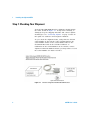
Step 1: Checking Your Shipment
Your 82357B USB/GPIB Interface shipment should include
the items shown in Figure 1- 1. If any item is missing or
damaged, keep the shipping materials and contact Agilent
Technologies. See “Contacting Agilent” on page 37 later in
this guide for addresses and telephone numbers.
As you check the shipment items, verify that the 82357B
serial number at the bottom of the 82357B matches the
serial number shown on the serial number label of the
82357B Kit Box and on the 82357B Certificate of
Calibration. If the Serial Numbers do not match, contact
Agilent. If all Serial Numbers match, you may want to record
the Serial Number for future reference.
Figure 1-1 Contents of Agilent 82357B USB/GPIB Interface
2
82357B User’s Guide
Installing the Agilent 82357B
1
Step 2: Installing Agilent IO Libraries Suite
NOTE
You must have Administrator privileges to install Agilent IO Libraries Suite
Connection Expert.
This section describes how to install the Agilent IO Libraries
Suite on your PC. The Agilent IO Libraries Suite is a
collection of libraries and utilities that gives you the ability
to use your instruments from instrument control software.
You should install the Agilent IO Libraries Suite as your first
step before installing the hardware because it installs the
necessary software and drivers to control your instruments.
If possible, always use the most recent version of the Agilent
IO Libraries Suite. This version supports the newest
interfaces and operating systems, and has the most
advanced features.
1 Verify that your PC meets the minimum system
requirements. Refer to the IO Libraries Web page at
www.agilent.com/find/iosuite or the IO Libraries
Suite Readme.
2 Close all applications on your computer. Insert the Agilent
Automation- Ready CD in your CD- ROM drive or download
and install the IO Libraries software from
www.agilent.com/find/iosuite.
3 Follow the instructions as prompted during the
installation. You can select either a Typical or a Custom
installation:
• Typical - In most cases, you can select the Typical
installation which installs the IO Libraries Suite using
the recommended settings.
82357B User’s Guide
3
1
Installing the Agilent 82357B
• Custom - Select the Custom installation to:
a Install the IO Libraries Suite in another directory
(for 32- bit operating systems only).
b Save disk space by not installing interface manuals.
c Use Agilent 32- bit VISA with another vendor's VISA
on the same PC in side- by- side mode. Details on
side- by- side mode are available at
www.agilent.com/find/side- by- side- install or in the
IO Libraries Suite help.
4 After the IO Libraries suite is successfully installed, you
will see the IO icon on the Windows taskbar
notification area.
Figure 1-2 IO icon on the Windows taskbar notification area
4
82357B User’s Guide
Installing the Agilent 82357B
1
Step 3: Connecting the 82357B
After the Agilent IO Libraries Suite software has been
installed, you can connect the 82357B to any USB port on
your PC or you can connect the 82357B via standard USB
hubs.
NOTE
If the Agilent IO Libraries Suite software have not been installed on your
PC, STOP. Install the libraries (see Step 2: Installing Agilent IO Libraries
Suite).
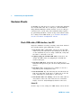
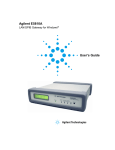
82357B hardware description
The Agilent 82357B provides a direct interface connection
from your PC USB port to GPIB instruments. The 82357B
includes an attached USB cable that is USB 2.0 compliant.
This cable is shielded and the connector is specified for up
to 1,500 insertions. An 82357B can be directly connected to
a single GPIB instrument or up to 14 GPIB instruments via
GPIB cables. Up to four 82357B converters may be
connected to your PC via standard USB hubs.
GPIB Connector
(Connect up to
14 GPIB instruments)
Green ACCESS LED
Green READY LED
Red FAIL LED
USB Cable
(Connect to USB port)
Figure 1-3 82357B Hardware Features
82357B User’s Guide
5
1
Installing the Agilent 82357B
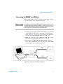
Connecting the 82357B to your PC
This section shows steps to connect the 82357B to a USB
port on your PC or to your PC via a USB Hub.
1 Connect to a USB Port. Make sure the PC is ON and
plug the 82357B USB cable into any available USB port
on your PC. Do not connect the 82357B to GPIB
instruments at this time.
Figure 1-4 Connecting the 82357B to Your PC
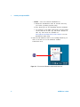
2 Observe the LEDs. Observe the LEDs on the 82357B for
at least 10 seconds. See Chapter 2, “Using the Agilent
82357B” for a description of the normal LED sequence
during an initial installation of the 82357B.
a Initially, only the red FAIL LED should be ON. After a
few seconds, all three LEDs should be ON. When all
three LEDs are ON, this shows that the 82357B has
been successfully installed.
b If all three LEDs are not ON after 10 seconds and all
Windows Plug- and- Play Manager activity has ceased,
STOP. See Chapter 3, “Troubleshooting the Agilent
82357B” for diagnostics information.
6
82357B User’s Guide
Installing the Agilent 82357B
1
Connecting the 82357B to a USB hub
This section shows steps to connect the 82357B to a USB
port on your PC via a standard USB hub.
NOTE
Any USB hub used with the 82357B MUST be self-powered (must not be
bus-powered or powered from the USB bus). Also, be sure to check the
applicable USB hub documentation for hub operating parameters, such as
power requirements and maximum length of USB cables.
1 Plug the power adapter into the hub and into an electrical
outlet. Make sure the hub is operating in self- powered
mode. Figure 1- 5 shows a 4- port self- powered USB hub
with two 82357B USB/GPIB Interfaces connected.
2 Make sure your PC is ON. Connect the USB cable of the
USB hub to any available USB port on your PC.
3 Plug at least one 82357B USB/GPIB Interface into the
port of the USB hub. It is not necessary to connect GPIB
instruments to any 82357B at this time.
Figure 1-5 Connecting the 82357B to a USB Hub
82357B User’s Guide
7
1
Installing the Agilent 82357B
4 Observe the LEDs on the 82357B for at least 10 seconds.
See Chapter 2, “Using the Agilent 82357B” for a
description of the normal LED sequence during an initial
installation of the 82357B.
a Initially, only the red FAIL LED should be ON. After a
few seconds, all three LEDs should be ON. When all
three LEDs are ON, this shows that the 82357B has
been successfully installed.
b If all three LEDs are not ON after 10 seconds and all
Windows Plug- and- Play Manager activity has ceased,
STOP. See Chapter 3, “Troubleshooting the Agilent
82357B” for diagnostics information.
NOTE
8
For Windows Vista, Windows 7, and Windows 8, there will be no Windows
Plug and Play Manager Sequence because once 82357B is initially
plugged into a USB port it will automatically install the driver.
82357B User’s Guide
Installing the Agilent 82357B
1
Step 4: Connecting GPIB Instruments
After the 82357B has been installed, the next step is to
connect GPIB instruments to the 82357B. This step includes:
• Connecting a Single GPIB instrument OR ...
• Connecting Multiple GPIB Instruments
CAUTION
To avoid damage to the connectors, only finger-tighten the connectors.
Connecting a single GPIB instrument
Figure 1- 6 shows connection from a single GPIB instrument
to the GPIB port on an 82357B. When you have made the
connection for your system, go to Step 5: Programming via
the 82357B. You may want to record the primary GPIB
address of the attached instrument for future programming
use.
Figure 1-6 Connection from Single GPIB Instrument to the GPIB Port
82357B User’s Guide
9
1
Installing the Agilent 82357B
Connecting multiple GPIB instruments
Figure 1- 7 shows a typical way to connect three GPIB
instruments to an 82357B. When you have made the
connections for your system, go to Step 5: Programming via
the 82357B. You may want to record the primary GPIB
address of each attached instrument for future programming
use.
NOTE
Although Figure 1-7 shows the connection from 82357B to GPIB
Instrument 1, the connection can be to any GPIB instrument in the system.
Be sure to first connect the GPIB cable to the GPIB instrument and then
“piggy-back” the 82357B GPIB connector to the GPIB cable.
*To minimize stress on the connector
mountings, stack no more than three cable
connector blocks.
Figure 1-7 Typical Way of Connecting Three GPIB instruments to an
82357B
10
82357B User’s Guide
Installing the Agilent 82357B
1
Step 5: Programming via the 82357B
After you have connected your GPIB instrument(s) to the
82357B, the next step is to establish communication between
your PC and the instruments using Interactive IO. After
communication has been established, you can begin
programming the instruments using VISA, VISA COM, or
SICL.
Establishing instrument communication
When the Agilent IO Libraries Suite is installed on your PC,
an IO utility called Interactive IO is also installed. You can
use Interactive IO to verify communication between your PC
and the connected GPIB instrument(s). This section shows
you how to use Interactive IO to verify instrument
communication.
NOTE
Once your GPIB interface has been configured in Connection Expert, if you
can see the attached GPIB instrument(s) in the Connection Expert explorer
and see their IDN string information in the detail pane then
communication has been verified. Interactive IO allows you to manually
verify communication and send specific commands to your instruments.
1 Click the IO icon on the Windows taskbar notification
area.
2 Right- click the instrument and click Send Commands To This
Instrument to display the Interactive IO window. For
information on Interactive IO, click Help.
3 *IDN? is the default command. Click Send & Read to send
the identification query to the instrument and display its
reply in the Interactive IO window.
82357B User’s Guide
11
1
Installing the Agilent 82357B
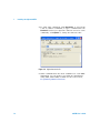
4 To send other commands, click Commands> to select from
a list of common commands, or type a command into the
Command: field. If you experience timeout errors for some
commands, click Options to change the timeout value.
Figure 1-8 Agilent Interactive IO
5 When communication has been established to each GPIB
instrument, you can begin to program the instruments
using VISA, VISA COM, or SICL. See the next section,
Programming GPIB instruments.
12
82357B User’s Guide
Installing the Agilent 82357B
1
Programming GPIB instruments
This section provides an introduction to programming GPIB
instruments via the 82357B USB/GPIB interface using the
Agilent VISA, VISA COM, and SICL IO Libraries. You can
program in various languages/applications, including Visual
Basic, Visual C++, Agilent VEE, and National Instruments
LabVIEW.
See the applicable user’s guide(s), such as the Visual Basic
User’s Guide, for programming guidelines. You can also find
additional programming examples using various IO Libraries
and instrument drivers in the instrument user’s guide. After
the 82357B is successfully installed, the interface acts as a
transparent interface for programming GPIB instruments.
For information on programming using Agilent VISA, see the
Agilent VISA User’s Guide. For information on VISA COM and
for function references for VISA, VISA COM, and SICL, see
the IO Libraries Suite Online Help.
Accessing VISA and SICL manuals
You can access .pdf copies of the Agilent VISA User’s Guide
and the Agilent SICL User’s Guide for Windows from the IO
icon on the Windows taskbar. Adobe Reader is required to
view these manuals.
To access the Agilent VISA User’s Guide, click the IO icon
then click Documentation > VISA Users Guide. To access the
Agilent SICL User’s Guide for Windows, click the IO icon then
click Documentation > SICL Users Guide. To access VISA COM
information, and function references for VISA, VISA COM,
and SICL, click the IO icon, then click Help Topics.
82357B User’s Guide
13
1
Installing the Agilent 82357B
Introduction to IO interface configuration
An IO interface consists of a hardware interface and a
software interface. The Connection Expert utility is used to
associate a unique software interface ID with a hardware
interface.
The Agilent IO Libraries Suite uses an Interface ID or
Logical Unit (LU) Number to identify an interface. This
information is passed in the parameter string of the viOpen
function call in a VISA program or in the iopen function call
in an SICL program.
The Connection Expert assigns an Interface ID and Logical
Unit (LU) Number to the interface hardware, as well as
other necessary configurations. Typically, the LU Number is
automatically assigned and you can ignore its setting. The
LU Number is used internally as a unique identifier. When
the IO interface is configured, you can use Agilent VISA,
VISA COM, or SICL to program assigned instruments.
Example: IO interface configuration
For example, the GPIB interface system in the Figure 1- 9
consists of a Windows PC, an 82357B USB/GPIB interface,
and three GPIB instruments with GPIB primary addresses of
3, 4, and 5, respectively. The instruments are connected via
GPIB cables.
For this system, the Connection Expert utility has assigned a
VISA name of “GPIB1” and a SICL name of “gpib1”. With
these names assigned to the interfaces, the VISA/SICL
addressing is as shown in Figure 1- 9.
Since unique names have been assigned by the Connection
Expert, you can use the VISA viOpen command or the SICL
iopen command to open the IO paths to the GPIB
instruments as shown in the figure.
14
82357B User’s Guide
Installing the Agilent 82357B
1
Figure 1-9 Typical System Installation - 82357B USB/GPIB Interface
82357B User’s Guide
15
1
Installing the Agilent 82357B
THIS PAGE HAS BEEN INTENTIONALLY LEFT BLANK.
16
82357B User’s Guide
Agilent 82357B USB/GPIB Interface
User’s Guide
2
Using the Agilent 82357B
This chapter describes normal operating states and modes
for the 82357B and provides the guidelines to use the
82357B, including:
• Initial 82357B operating states
• Introduction to 82357B operating modes
• Single 82357B operation
• Multiple 82357B operation
• SRQ operation
Agilent Technologies
17
2
Using the Agilent 82357B
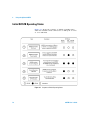
Initial 82357B Operating States
Figure 2- 1 shows the sequence of initial operating states
when the 82357B is first connected to a USB port on a PC
or on a USB hub.
Figure 2-1 Sequence of Initial Operating States
18
82357B User’s Guide
Using the Agilent 82357B
2
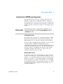
Introduction to 82357B operating modes
The 82357B has two modes of operation. When only one
82357B is connected to a USB port within a system, we
define the feature as the Single Mode Features. When up to
four 82357Bs are connected at the same time to USB ports
within a system, we define the feature as the Multiple Mode
Features.
NOTE
All SICL/VISA applications are notified when their 82357B has been
removed from the system by returning VI_ERR_NOINFC (for VISA) or
I_ERR_NCIC (for SICL).
Single Mode Features
For single mode operation, the operating parameters (VISA
Interface ID, SICL Interface ID, Logical Unit Number, and
GPIB Address) are set when the 82357B is first installed.
If this 82357B is unplugged and replugged, or if the 82357B
is replaced with a different 82357B, the previous
configuration parameters are automatically assigned to the
newly attached 82357B. Thus, you can exchange 82357Bs at
any time without reconfiguring the interface. This allows
exchanging 82357Bs among users, as long as only one
82357B is attached at any one time.
Multiple Mode Features
In contrast, when up to four 82357Bs are connected to the
system at the same time, each 82357B must have its own
specific set of operating parameters and each 82357B serial
number is “bound” to its operating parameters. In multiple
mode operation, if you add a new 82357B or if you unplug
an 82357B and plug in a new 82357B in its place, the newly
installed 82357B, will be assigned a new (unique) set of
operating parameters.
82357B User’s Guide
19
2
Using the Agilent 82357B
Single 82357B operation
When an 82357B is first installed, a default VISA Interface
ID, SICL Interface ID, Logical Unit (LU) number and GPIB
Address are automatically assigned to the serial number
associated with this specific 82357B.
For example, assume an 82357B with serial number
MY12345678. When this 82357B is first installed, typical
values as shown are automatically assigned to this serial
number:
• VISA Interface ID: GPIB0
• SICL Interface ID: gpib0
• Logical Unit: 7
• GPIB Address: 21
NOTE
You can change the parameter values of the 82357B as required. See
“Changing configuration parameters” on page 23 for details.
The first time an 82357B is attached to a system (assuming
the Agilent IO Libraries Suite and 82357B driver are
installed), the software recognizes that an 82357B is
attached. If the Connection Expert is not running, the
software displays an Agilent 82357B USB/GPIB Interface Detected
dialog box that allows you to accept the current settings. If
the Connection Expert is running, it automatically refreshes,
displaying the 82357B as a USB/GPIB interface in its tree
view. You can then change the properties of the interface via
the Connection Expert.
The VISA and SICL Interface IDs, Logical Unit Number, and
GPIB Address may be viewed at any time in the property
pane of the Connection Expert. (To view this window, click
the IO icon, then select Agilent Connection Expert.)
20
82357B User’s Guide
Using the Agilent 82357B
2
If you disconnect this 82357B and plug in another 82357B
(with a different serial number), or if you re- plug the same
82357B, the new 82357B will assume the same VISA
Interface ID, SICL Interface ID, LU number, and GPIB
Address as the previous 82357B.
Multiple 82357B operation
When two or more 82357Bs are attached to a system at the
same time, we define the mode as the multiple mode of
operation. In multiple mode of operation, each 82357B is
“bound” to its related IO Configuration for that Serial
Number. This is a different mode of operation than the
single mode of operation in that the configuration is not
reused if you replace an 82357B with another 82357B.
As with single mode operation, the first time an 82357B is
attached to a system (assuming the Agilent IO Libraries
Suite and 82357B driver are installed), the software
recognizes that an 82357B is attached. If the Connection
Expert is not running, the software displays an Agilent 82357B
USB/GPIB Interface Detected dialog box that allows you to
accept the current settings. If the Connection Expert is
running, it automatically refreshes, displaying the 82357B as
a USB/GPIB interface in its tree view; you can then change
the properties of the interface in the Connection Expert.
The VISA and SICL Interface IDs, Logical Unit Number, and
GPIB Address may be viewed at any time in the property
pane of the Connection Expert. (To view this window, click
the IO icon, then select Agilent Connection Expert.)
If you plug in another 82357B (with a different Serial
Number), the new 82357B will automatically be assigned a
unique VISA Interface ID, SICL Interface ID, LU, and GPIB
Address.
82357B User’s Guide
21
2
Using the Agilent 82357B
NOTE
• You can change the parameter values of the 82357B as required. See
“Changing configuration parameters” on page 23 for details.
• You can also convert from multiple mode operation to single mode
operation. See “Changing modes of operation” on page 24 for details.
SRQ operation
If your VISA/SICL application uses SRQ callbacks
(viEventHandler() in VISA or ionsrq() in SICL) and your
callback does not service the SRQ in a timely manner, your
SRQ callback function may be triggered multiple times.
To avoid this possible situation, design your SRQ callback
functions to be called only when an SRQ is no longer
asserted on the GPIB bus.
22
82357B User’s Guide
Using the Agilent 82357B
2
Setting Configuration Parameters
This section gives guidelines to change or set various
configuration parameters for the 82357B, including:
• Changing Configuration Parameters
• Changing Modes of Operation
• Setting Timeout Floor Value
• Setting High- Performance Operation
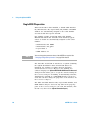
Changing configuration parameters
To change the VISA or SICL Interface ID, the LU or GPIB
Address, or if you want to check the values of these
configuration parameters, highlight the USB/GPIB interface
in the explorer view (tree view) of the Connection Expert
window. Click on the Change Properties... button in the
property pane to display the Agilent 82357 Interface dialog box.
Choose the settings you want, then click OK. Clicking Cancel
will cause the configuration set in the preceding dialog box
to be used.
NOTE
82357B User’s Guide
Although you can change the Logical Unit (LU) Number and GPIB Address
values for an 82357B, this is generally not necessary and may cause
running applications to fail or stop running.
23
2
Using the Agilent 82357B
Figure 2-2 Agilent 82357B (High Speed) Interface - USB/GPIB
Changing modes of operation
If your system has multiple 82357Bs configured (multiple
mode operation), the only way to change from multiple mode
of operation to single mode operation is to perform the
following:
1 Unplug all 82357Bs from the system.
2 Run Connection Expert (click the IO icon, then click
Agilent Connection Expert).
3 Delete all 82357B configurations by selecting each
USB/GPIB icon in the explorer view, then clicking Delete
(or delete all except one configuration).
4 Re- attach and re- configure a single 82357B.
24
82357B User’s Guide
Using the Agilent 82357B
2
Setting timeout floor values
The 82357B has a default timeout “floor” value that is an
internal requirement to ensure reliable USB communication.
The 82357B will not allow timeouts less than the floor value.
(By default, VISA/SICL timeouts are set to infinite time).
To programmatically determine the timeout floor, you can
set the timeout to a very small value, such as 1 ms, then
query for the actual timeout floor value. VISA and SICL
examples are as follows:
Example: Query Timeout Floor (VISA)
tval = 1;
// Try to set timeout to 1 msec
err = viSetAttribute(id, VI_ATTR_TMO_VALUE,
tval_in);
...
err = viGetAttribute(id, VI_ATTR_TMO_VALUE,
&tval_out);
...
printf("Set timeout to [%d], actual timeout that
resulted [%d]\n", tval_in, tval_out );
Example: Query Timeout Floor (SICL)
tval = 1;
// Try to set timeout to 1
msec
err = itimeout(id, tval_in);
...
err = igettimeout(id, &tval_out);
...
printf("Set timeout to [%d], actual timeout that
resulted [%d]\n",tval_in, tval_out );
82357B User’s Guide
25
2
Using the Agilent 82357B
Setting 82357B high-performance operation
NOTE
Changing the T1 delay as described in this section is an advanced feature
and also requires attention to cable lengths and other system features.
Introduction
The GPIB transfer rate for 82357B writes using large (>1000
bytes) buffer size is affected by the Data Available (T1) delay
time. (The transfer rates are not noticeably affected when
the buffer size is <1000 bytes). The default delay time used
by the 82357B is 800 ns.
The maximum transfer rate for T1 = 357 ns is about 1.15
MB/s as compared to about 714 KB/s for the 82357B default
value of 800 ns. Changing the T1 delay affects only the write
performance of the 82357B.
Setting T1 Value With VISA
To set the T1 value with VISA, use the
VI_AGATTR_GPIB_T1_DELAY attribute. The
VI_AGATTR_GPIB_T1_DELAY value is the value of the T1
delay in nanoseconds, and should be no less than
VI_AG_GPIB_T1DELAY_MIN and no greater than
VI_AG_GPIB_T1DELAY_MAX. This value is defined in
Agilent’s ‘visa.h’ header file. To use this value, you must
'#define AGVISA_ATTRIBUTES' before the ‘#include
‘visa.h’‘ in your C or C++ source file.
The 82357B supports T1 delays from 357 ns to <max_value>
in steps of 40 ns. You can find out the actual value by
calling viGetAttribute().
Attribute
Access
Privilege
Data Type
Range (ns)
Used By
VI_AGATTR_GPIB_
T1_DELAY
RW Global
ViInt32
VI_AG_GPIB_T1DELAY_MIN to
GPIB INTFC
resources
VI_AG_GPIB_T1DELAY_MAX
Setting T1 Value With SICL
To set T1 value with SICL, use the igpibsett1delay()
command and modify the GPIB environment.
26
82357B User’s Guide
Agilent 82357B USB/GPIB Interface
User’s Guide
3
Troubleshooting the Agilent 82357B
This chapter provides troubleshooting guidelines of the
82357B including hardware and software checks and also
the service and support information for the 82357B.
Agilent Technologies
27
3
Troubleshooting the Agilent 82357B
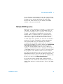
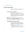
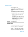
Troubleshooting Flowchart
Figure 3- 1 shows a suggested sequence of steps to diagnose
and troubleshoot 82357B problems, based on the LED states.
You can use the LED states to help diagnose and
troubleshoot the 82357B whenever the LED states do not
match expected normal states. See Chapter 2, “Using the
Agilent 82357B” for the normal LED sequence when the
82357B is initially connected to a USB port.
Observe the LED states
To begin troubleshooting, observe the LED states for at least
10 seconds after the 82357B is connected to a USB port and
all Windows Plug- and- Play Manager activity has ceased. Do
the following:
• If all LEDs are OFF, start with Hardware Checks
• If the red FAIL LED is ON, start with Software
Installation Checks
• If all LEDs are ON, start with Software Configuration
Checks
After taking the steps in the check sequence, use the boxes
in Figure 3- 1 to determine the next step. For example, if
doing a hardware check results in only the red FAIL LED
being ON, proceed with Software Installation Checks, and
so on.
NOTE
28
You do not have to do all the steps or do the steps in the order shown. If
any action results in a change in LED states, go to the applicable check
sequence to continue troubleshooting.
82357B User’s Guide
Troubleshooting the Agilent 82357B
3
START
All LEDs OFF
READY
FAIL
Red Fail LED ON
ACCESS
READY
FAIL
ALL LEDs ON
ACCESS
READY
FAIL
ACCESS
Typical Cause
Typical Cause
Typical Cause
No power on USB bus or
device turned off by Windows
Plug and Play Manager.
Agilent IO Libraries not
installed or 82357B USB
drivers not installed.
Improper Agilent IOLibraries
configuration.
Hardware Checks
Software Installation
Checks
Software Configuration
Checks
Check Cables, USB
Interface, Host PC
Check Suspend /
Resume Operation
Check IO Control Operation
Reboot PC
Verify Agilent IO Libraries
Installation
Check USB Scanner
Check Device Manager
Verify Driver Installation
After Doing These Checks:
After Doing These Checks:
After Doing These Checks:
If the FAIL LED is the only LED
ON, go to Software Installation
Checks.
If all three LEDs are ON, go to
Software Configuration Checks.
If all three LEDs are ON, contact
Agilent.
If all three LEDs are ON, go to
Software Configuration Checks.
If the FAIL LED is the only LED
ON, contact Agilent.
If all three LEDs are OFF, contact
Agilent.
Figure 3-1 Troubleshooting Flowchart
82357B User’s Guide
29
3
Troubleshooting the Agilent 82357B
Hardware Checks
If all LEDs are still off for 10 or more seconds after plugging
the 82357B USB cable into a USB port, and all Windows
Plug- and- Play Manager activity and the Connection Expert
refreshes have ceased, start your troubleshooting sequence
by performing hardware checks. If any action taken results
in a change in the LED status, go to Software Installation
Checks or Software Configuration Checks.
Check USB cables, USB interface, host PC
Begin the hardware check by checking connections between
the 82357B and PC (plus USB hubs, if used).
1 Check USB cable connections. Check the 82357B USB
cable for a good connection to the USB port on the PC or
on the USB hub. If you are using a USB hub, verify that
the hub is connected to the PC.
2 Unplug/replug the 82357B USB cable. If this does not
change the LED status, try plugging the 82357B into
another USB port.
3 Check PC USB Port. Verify that the PC USB port is
functional and powered (you can check using another USB
device).
4 Check PC state. Verify that host computer is not in a
suspended power management state.
5 Check USB hub. Try disconnecting the 82357B from the
hub and connecting it directly to a USB port on the PC.
Some USB hubs are vulnerable to static shock.
6 Check USB cables for damage. Check the USB cable for
cuts/crushes. Since the end connectors are somewhat
fragile, check for bent/misaligned/crushed connectors.
Reboot PC
If these steps do not change the LED status, reboot the PC.
30
82357B User’s Guide
Troubleshooting the Agilent 82357B
3
Check Device Manager
You can use the Windows Device Manager to reinstall the
82357B, as required.
Go to Device Manager by selecting Start > Control Panel > System
> Hardware > Device Manager.
For Windows 8, right- click the bottom- left corner of the
Desktop and select Device Manager.
From the Device Manager, select 82357 and then Properties. Tab
to Driver and click Reinstall Driver. This will allow the
Windows Plug- and- Play Manager to begin searching for a
driver for the 82357B. Since the Device Manager may have
disabled the 82357B USB device, click Enable to restart the
82357B.
NOTE
82357B User’s Guide
If you are using a USB scanner, scanner conflicts are possible. See Check
USB scanner in the “Software Installation Checks” on page 32.
31
3
Troubleshooting the Agilent 82357B
Software Installation Checks
When only the red FAIL LED is still on after 10 seconds, the
82357B has been detected by the host computer.
Check suspend/resume operation
Some Windows operating systems support Power
Management which can suspend the PC while the 82357B is
in operation. After a Suspend/Resume cycle, the 82357B may
not properly resume operation. In this case, you may need to
unplug/replug the USB cable to restore 82357B operation. If
this does not correct the problem, go to Verify Agilent IO
Libraries Suite installation.
NOTE
If your 82357B applications must not be preempted by a PC Suspend
event, we recommend you to disable Power Management on your PC by
using the Control Panel > Power Options dialog.
Verify Agilent IO Libraries Suite installation
When only the red LED is on after 10 seconds and all
Windows Plug and Play Manager activity has ceased, start
your troubleshooting sequence by verifying IO Libraries
installation. If any action taken results in a change in the
LED status, go to Software Configuration Checks or
Hardware Checks.
1 Check Agilent IO Libraries Version. If a version of the
IO Libraries Suite has been installed, the IO icon is
normally displayed on the Windows taskbar notification
area.
32
82357B User’s Guide
Troubleshooting the Agilent 82357B
3
Figure 3-2 IO icon on the Windows taskbar notification area
a If the IO icon is displayed, click the icon and select
About Agilent IO Control to display the version. The version
must be 15.0 or greater.
b If the IO icon is not displayed, a version of the IO
Libraries Suite may still be installed. To verify this,
check for Agilent Connection Expert in the Start menu,
or the Start Screen (Windows 8).
c If found, launch the Agilent Connection Expert and
select View > Agilent IO Control to place a check mark next
to the Agilent IO Control selection.
d If Agilent Connection Expert is not found in the Start
menu or the Start Screen (Windows 8), no version of
Agilent IO Libraries is installed. In this case, or if the
installed version is not 15.0 or greater, you must install
the newer version (see Step 2).
82357B User’s Guide
33
3
Troubleshooting the Agilent 82357B
2 Install Agilent IO Libraries (as required). If Version 15.0
or greater of the Agilent IO Libraries Suite is not installed
on your PC, perform this step.
a Remove the 82357B USB cable from the USB port.
b Insert the Automation- Ready CD into your CD- ROM
drive and follow the instructions in Chapter 1,
“Installing the Agilent 82357B” to install the libraries. If
you do not have the Automation- Ready CD, you can
download the Agilent IO Libraries Suite from
www.agilent.com/find/iolib
c Re- attach the 82357B USB cable to the USB port and
observe the LEDs for at least 10 seconds.
If all three LEDs remain ON, go to Software
Configuration Checks.
34
82357B User’s Guide
Troubleshooting the Agilent 82357B
3
Software Configuration Checks
If all three LEDs remain on for more than 10 seconds after
the 82357B is connected to a USB port, the 82357B has been
installed.
Start your troubleshooting sequence by checking IO Control
operation. If any action taken results in a change in the LED
status, go to Software Installation Checks or Hardware
Checks, where applicable.
Checking IO Control operation
When the Agilent IO Libraries Suite is installed, an IO
Control is created. When the IO Control is active, it is
displayed as an IO icon on the Windows taskbar. By default,
the IO Control is always active after the libraries are
installed and the IO icon is displayed. However, there may
be times when the IO Control can get deactivated. When this
happens, SICL/VISA applications that are running with the
82357B will malfunction. Any of the following symptoms may
indicate the IO Control is not active:
• Connection Expert is not running, and the Agilent 82357B
USB/GPIB Interface Detected dialog box does not appear
when an 82357B is first connected to a USB port.
• Connection Expert is running, but does not automatically
refresh when an 82357B is first connected to a USB port.
• SICL/VISA applications using the 82357B are unable to
open sessions.
• Windows Task Manager shows that iproc82357.exe is not
running or is non- responsive.
82357B User’s Guide
35
3
Troubleshooting the Agilent 82357B
If any of these symptoms occur:
1 Unplug/Replug the 82357B. If unplugging then replugging
the 82357B causes the Agilent 82357B USB/GPIB Interface
Detected dialog box to appear or the Connection Expert
window to refresh, the problem is solved. If not, go to
Step 2.
2 Shut down and restart IO Control. Take these steps to
shut down and then restart the IO Control. Taking these
actions should initialize all attached 82357Bs and display
only the green Ready LED.
a If the IO icon is displayed, click the icon and then click
Exit. A dialog box explaining the consequences of
removing the IO Control appears. Click OK to shut
down the IO Control.
b If the IO icon is not displayed, either the icon display
has been turned off or the IO Control (and associated
iproc82357.exe and iprocsvr.exe) is not active. In this
case, launch the Agilent Connection Expert and select
View > Agilent IO Control to place a check mark next to
the Agilent IO Control selection to restart the
IO Control and display the IO icon.
NOTE
Rebooting your PC should ALWAYS restart the IO Control, and re-execute
iprocsvr.exe and iproc82357.exe.
Check USB scanner
In general, USB scanners do not cause problems with the
82357B. However, if you do have problems with 82357B
operation and have a scanner installed on your system that
uses a USB port, unplug the scanner and then plug the
82357B into the port.
If the 82357B is configured without your scanner attached to
your system, the scanner will be locking the 82357B from
using the USB bus. In this case, contact your scanner
manufacturer to request for software or firmware updates
for the scanner.
36
82357B User’s Guide
Troubleshooting the Agilent 82357B
3
Service and Support Information
There are no user- serviceable parts for the Agilent 82357B
USB/GPIB interface. If you suspect a hardware failure for
the 82357B, contact Agilent for instructions to return the
unit. See the following Contacting Agilent section for
telephone numbers/Web site address.
Contacting Agilent
You can reach Agilent Technologies at this telephone number
for the Americas:
Americas Call Center:
1- 800- 829- 4444
For other countries, contact your country’s Agilent support
organization. A list of contact information for other
countries is available on the Agilent Web site:
www.agilent.com/find/assist
82357B User’s Guide
37
3
Troubleshooting the Agilent 82357B
THIS PAGE HAS BEEN INTENTIONALLY LEFT BLANK.
38
82357B User’s Guide
Agilent 82357B USB/GPIB Interface
User’s Guide
4
Product Specifications
This chapter lists the 82357B technical specifications and
supplementary information.
Agilent Technologies
39
4
Product Specifications
Technical Specifications
GENERAL REQUIREMENTS
Minimum system requirements
Windows XP Service Pack 3
• 600 MHz or higher required (800 MHz recommended)
• 256 MB RAM (1 GB or greater is recommended)
• Hard Disk Space
- 1.0 GB available for Microsoft .NET Framework 3.5, SP1
- 100 MB for Agilent IO Libraries Suite
• Video
- Super VGA (800x600) 256 colors or more
• Browser
- Microsoft Internet Explorer 6.0 or greater
Windows Vista SP1 and SP2 (32-bit and 64-bit), Business, Ultimate, Enterprise,
Home Basic, and Home Premium
• 1 GHz 32-bit (x86), 1 GHz 64-bit (x64), no support for Itanium64
• 1GB minimum
• Hard Disk Space
- 1.0 GB available for Microsoft .NET Framework 3.5, SP1
- 100 MB for Agilent IO Libraries Suite
• Video
- Support for DirectX 9 graphics with 128 MB graphics memory
recommended (Super VGA graphics is supported)
• Browser
- Microsoft Internet Explorer 7 or greater
Windows 7 (with or without SP1) (32- and 64-bit), Home Basic, Home Premium,
Professional, Ultimate, and Enterprise, or Windows 8
• 1 GHz 32-bit (x86), 1 GHz 64-bit (x64), no support for Itanium64
• 1GB minimum
• Hard Disk Space
- 1.0 GB available for Microsoft .NET Framework 3.5, SP1
- 100 MB for Agilent IO Libraries Suite
• Video
- Support for DirectX 9 graphics with 128 MB graphics memory
recommended (Super VGA graphics is supported)
• Browser
- Microsoft Internet Explorer 7 or greater
40
82357B User’s Guide
Product Specifications
4
Windows Server 2008 R2 (with or without SP1) (64-bit) Standard and Enterprise
• 1.4 GHz (x64 processor) or 1.3GHz (Dual Core), no support for Itanium64
• 1GB minimum
• Hard Disk Space
- 1.0 GB available for Microsoft .NET Framework 3.5, SP1
- 100 MB for Agilent IO Libraries Suite
• Video
- Support for DirectX 9 graphics with 128 MB graphics memory
recommended (Super VGA graphics is supported)
• Browser
- Microsoft Internet Explorer 7 or greater
Supported standards
•
•
•
•
Support USB 2.0 high speed and full speed
Standard USB endpoints supported
IEEE-488.1 and IEEE-488.2 compatible
SICL and VISA 2.2
Supported applications (with IntuiLink)
• Microsoft Excel 97 and 2000
• Microsoft Word 97 and 2000
• Check the web for latest supported applications
Supported software development
applications
• Visual Basic 6.0
• Visual Studio .NET
• BASIC for Windows
• Visual C++ 6.0
• Agilent VEE 6.0 or greater
• LabVIEW 6.0 or greater
GENERAL CHARACTERISTICS
Power
USB bus-powered device, +5 V, 500 mA (max), 200 mA (typ)
GPIB transfer rate
1.15 MB/s
Connectors
Standard 24-pin IEEE-488, Standard USB A
USB hubs
Self-powered hubs
Parallel polling
A single parallel poll can easily check up to eight individual devices at once
corresponding to the number of data lines on the GPIB.
Dimensions
105 mm (L) x 64 mm (W) x 30 mm (H) (includes connectors)
Weight
215 grams
Cable
2.5 meters, shielded, connector rated for 1500 insertions
LED Indicators
READY, ACCESS, FAIL
Warranty
1 year
Maximum connections
Maximum 4 converters can be connected to the PC
Instrument connection
14 instruments – daisy chain via GPIB
Configuration
Plug-and-play
Pollution degree
2
82357B User’s Guide
41
4
Product Specifications
ENVIRONMENTAL SPECIFICATIONS
Operating environment
0 °C to 55 °C
Storage environment
–40 °C to +70 °C
Operating humidity
Up to 90 % at 40 °C non-condensing
Storage humidity
Up to 90 % at 65 °C non-condensing
ORDERING INFORMATION
Interface
82357B USB/GPIB Interface
Options
Opt 0B1 - Add manual set
Accessories
None
42
82357B User’s Guide
Product Specifications
4
Supplementary Information
This section provides supplementary information on the
82357B performance, including supported GPIB modes.The
82357B is defined as a controller as it can be (and is
required to be) the system controller.
GPIB Modes of Operation Supported
The 82357B supports standard GPIB modes of operation,
except for:
• Passing of Active Controller
• Non- system Controller mode which prevents using SICL
Commander sessions or VISA Servant sessions
IEEE-488.1 and IEEE-488.2 Compliance
The 82357B is in full compliance with IEEE 488.1 and
IEEE- 488.2 specifications. The 82357B fully supports
IEEE- 488.1 subsets AH1, C1, C2, C3, C4, C27, DC0, DT0,
LE3, PP0, RL0, SH1, SR0, and TE7.
SRQ Response Time
SRQ response time is slower than with the 82350 PCI GPIB
interface as an artifact of the USB implementation. In
addition, sharing the USB bus with other devices may
impact GPIB performance.
Default T1 Delay
The default T1 delay for the 82357B is 800 nsec. See “Setting
82357B high- performance operation” on page 26 in
Chapter 2, “Using the Agilent 82357B” for details.
Maximum 82357B System Configuration
Up to four 82357Bs on a system have been successfully
tested.
82357B User’s Guide
43
4
Product Specifications
THIS PAGE HAS BEEN INTENTIONALLY LEFT BLANK.
44
82357B User’s Guide
Index
Index
A
H
Agilent IO Libraries Suite, verify
installation, 32
Agilent telephone number, 37
Agilent Web site, 37
Hardware Checks, 30
Hardware Description, 5
High-Performance Operation, setting, 26
B
Before You Install, 2
C
Changing Configuration Parameters, 23
changing configuration parameters, 23
Changing Modes of Operation, 24
changing modes of operation, 24
check device manager, 31
Check IO Control Operation, 35
Check PC, 30
Check Shipment, 2
Check USB Cables, 30
Check USB Interface, 30
Check USB Scanner, 36
checking shipment, 2, 30
configuration parameters, changing, 23
configuration parameters, setting, 23
connecting 82357A to USB hub, 7
Connecting GPIB Instruments, 9
Connection Expert, 9, 14, 20, 21, 23, 24,
35, 36
D
I
Initial Operating States, 18
initial operating states, 18
Installing Agilent IO Libraries Suite, 3
interface ID, 14
Interface Name, 14
IO Control Operation checking, 35
IO interface, 14
IO Libraries Suite, checking for
installation, 32
iopen, 14
LED States, 18
LED states, 18
Logical Unit Number, 14
rebooting the PC, 30
Restricted Rights, iii
S
setting configuration parameters, 23
setting high-performance operation, 26
setting timeout floor values, 25
single 82357A operation, 20
Single 82357B Operation, 20
SRQ Operation, 22
SRQ operation, 22
suspend/resume operation, 32
T
telephone number, Agilent, 37
troubleshooting, 31
suspend/resume operation, 32
M
Modes of Operation, changing, 24
modes of operation, changing, 24
multiple 82357A operation, 21
Multiple 82357B Operation, 21
Multiple Mode of Operation, 19
multiple mode of operation, 19
P
E
Parallel Polling, 41
PC
power management, 32
suspend, 32
PC Checking, 30
PC Rebooting, 30
PC, rebooting, 30
82357B User’s Guide
R
L
Device Manager checking, 31
Environmental Requirements, ix
Example
IO Interface Configuration, 14
examples
IO Interface Configuration, 14
Programming GPIB Instruments, 13
programming GPIB instruments, 13
Programming via 82357B, 11
V
viOpen, 14
VISA Assistant, 11
W
warranty service, iii
Web site, Agilent, 37
45
Index
THIS PAGE HAS BEEN INTENTIONALLY LEFT BLANK.
46
82357B User’s Guide
www.agilent.com
Contact us
To obtain service, warranty, or technical
support assistance, contact us at the
following phone numbers:
United States:
(tel) 800 829 4444
(fax) 800 829 4433
Canada:
(tel) 877 894 4414
(fax) 800 746 4866
China:
(tel) 800 810 0189
(fax) 800 820 2816
Europe:
(tel) 31 20 547 2111
Japan:
(tel) 0120 (421) 345 (fax) 0120 (421) 678
Korea:
(tel) (080) 769 0800 (fax) (080) 769 0900
Latin America:
(tel) (305) 269 7500
Taiwan:
(tel) 0800 047 866
(fax) 0800 286 331
Other Asia Pacific Countries:
(tel) (65) 6375 8100 (fax) (65) 6755 0042
Or visit Agilent worldwide Web at:
www.agilent.com/find/assist
Product specifications and descriptions in
this document are subject to change without notice. Always refer to the English
version at the Agilent Web site for the latest
revision.
© Agilent Technologies, Inc. 2006–2014
Eighth Edition, June 13, 2014
82357-90003
Agilent Technologies