1
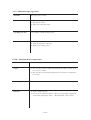
2-1-9. Linear encoder PCB
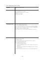
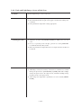
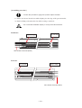
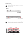
This board, located on the back of the slider, reads the linear scale.
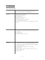
2-1-10. The KeyBoard PCB
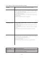
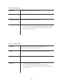
A 16 character x 2 line LCD, an LED that indicates +5V supply and 11 tact switches are
mounted on the K/B PCB. It is connected to the IO PCB via the K/B cable.
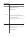
2-1-11. Take-up motor PCB
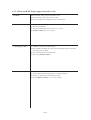
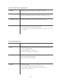
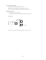
This board, located in the take-up device, drivers the motor by receiving the power from the
IO PCB. The forward or reverse rotation of the take-up motor can be selected using a switch.
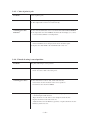
2-1-12. ID contact board
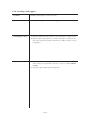
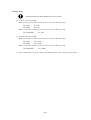
This board is a contact board of the ink cartridge ID. It is located in each cartridge slot.
– 2.13 –