1
Using Technician
Interface Software
BayRS Version 13.00
Site Manager Software Version 7.00
Part No. 303561-A Rev 00
October 1998
4401 Great America Parkway
Santa Clara, CA 95054
8 Federal Street
Billerica, MA 01821
Copyright © 1998 Bay Networks, Inc.
All rights reserved. Printed in the USA. October 1998.
The information in this document is subject to change without notice. The statements, configurations, technical data,
and recommendations in this document are believed to be accurate and reliable, but are presented without express or
implied warranty. Users must take full responsibility for their applications of any products specified in this document.
The information in this document is proprietary to Bay Networks, Inc.
The software described in this document is furnished under a license agreement and may only be used in accordance
with the terms of that license. A summary of the Software License is included in this document.
Trademarks
AN, BCN, BLN, BN, FRE, Optivity, PPX, and Bay Networks are registered trademarks and Advanced Remote Node,
ANH, ARN, ASN, BayRS, BaySecure, BayStack, BayStream, BCC, SPEX, System 5000, and the Bay Networks logo
are trademarks of Bay Networks, Inc.
Microsoft, MS, MS-DOS, Win32, Windows, Internet Explorer, and Windows NT are registered trademarks of
Microsoft Corporation.
All other trademarks and registered trademarks are the property of their respective owners.
Restricted Rights Legend
Use, duplication, or disclosure by the United States Government is subject to restrictions as set forth in subparagraph
(c)(1)(ii) of the Rights in Technical Data and Computer Software clause at DFARS 252.227-7013.
Notwithstanding any other license agreement that may pertain to, or accompany the delivery of, this computer
software, the rights of the United States Government regarding its use, reproduction, and disclosure are as set forth in
the Commercial Computer Software-Restricted Rights clause at FAR 52.227-19.
Statement of Conditions
In the interest of improving internal design, operational function, and/or reliability, Bay Networks, Inc. reserves the
right to make changes to the products described in this document without notice.
Bay Networks, Inc. does not assume any liability that may occur due to the use or application of the product(s) or
circuit layout(s) described herein.
Portions of the code in this software product may be Copyright © 1988, Regents of the University of California. All
rights reserved. Redistribution and use in source and binary forms of such portions are permitted, provided that the
above copyright notice and this paragraph are duplicated in all such forms and that any documentation, advertising
materials, and other materials related to such distribution and use acknowledge that such portions of the software were
developed by the University of California, Berkeley. The name of the University may not be used to endorse or
promote products derived from such portions of the software without specific prior written permission.
SUCH PORTIONS OF THE SOFTWARE ARE PROVIDED “AS IS” AND WITHOUT ANY EXPRESS OR
IMPLIED WARRANTIES, INCLUDING, WITHOUT LIMITATION, THE IMPLIED WARRANTIES OF
MERCHANTABILITY AND FITNESS FOR A PARTICULAR PURPOSE.
In addition, the program and information contained herein are licensed only pursuant to a license agreement that
contains restrictions on use and disclosure (that may incorporate by reference certain limitations and notices imposed
by third parties).
ii
303561-A Rev 00
Bay Networks, Inc. Software License Agreement
NOTICE: Please carefully read this license agreement before copying or using the accompanying software or
installing the hardware unit with pre-enabled software (each of which is referred to as “Software” in this Agreement).
BY COPYING OR USING THE SOFTWARE, YOU ACCEPT ALL OF THE TERMS AND CONDITIONS OF
THIS LICENSE AGREEMENT. THE TERMS EXPRESSED IN THIS AGREEMENT ARE THE ONLY TERMS
UNDER WHICH BAY NETWORKS WILL PERMIT YOU TO USE THE SOFTWARE. If you do not accept these
terms and conditions, return the product, unused and in the original shipping container, within 30 days of purchase to
obtain a credit for the full purchase price.
1. License Grant. Bay Networks, Inc. (“Bay Networks”) grants the end user of the Software (“Licensee”) a personal,
nonexclusive, nontransferable license: a) to use the Software either on a single computer or, if applicable, on a single
authorized device identified by host ID, for which it was originally acquired; b) to copy the Software solely for backup
purposes in support of authorized use of the Software; and c) to use and copy the associated user manual solely in
support of authorized use of the Software by Licensee. This license applies to the Software only and does not extend
to Bay Networks Agent software or other Bay Networks software products. Bay Networks Agent software or other
Bay Networks software products are licensed for use under the terms of the applicable Bay Networks, Inc. Software
License Agreement that accompanies such software and upon payment by the end user of the applicable license fees
for such software.
2. Restrictions on use; reservation of rights. The Software and user manuals are protected under copyright laws.
Bay Networks and/or its licensors retain all title and ownership in both the Software and user manuals, including any
revisions made by Bay Networks or its licensors. The copyright notice must be reproduced and included with any
copy of any portion of the Software or user manuals. Licensee may not modify, translate, decompile, disassemble, use
for any competitive analysis, reverse engineer, distribute, or create derivative works from the Software or user manuals
or any copy, in whole or in part. Except as expressly provided in this Agreement, Licensee may not copy or transfer
the Software or user manuals, in whole or in part. The Software and user manuals embody Bay Networks’ and its
licensors’ confidential and proprietary intellectual property. Licensee shall not sublicense, assign, or otherwise
disclose to any third party the Software, or any information about the operation, design, performance, or
implementation of the Software and user manuals that is confidential to Bay Networks and its licensors; however,
Licensee may grant permission to its consultants, subcontractors, and agents to use the Software at Licensee’s facility,
provided they have agreed to use the Software only in accordance with the terms of this license.
3. Limited warranty. Bay Networks warrants each item of Software, as delivered by Bay Networks and properly
installed and operated on Bay Networks hardware or other equipment it is originally licensed for, to function
substantially as described in its accompanying user manual during its warranty period, which begins on the date
Software is first shipped to Licensee. If any item of Software fails to so function during its warranty period, as the sole
remedy Bay Networks will at its discretion provide a suitable fix, patch, or workaround for the problem that may be
included in a future Software release. Bay Networks further warrants to Licensee that the media on which the
Software is provided will be free from defects in materials and workmanship under normal use for a period of 90 days
from the date Software is first shipped to Licensee. Bay Networks will replace defective media at no charge if it is
returned to Bay Networks during the warranty period along with proof of the date of shipment. This warranty does not
apply if the media has been damaged as a result of accident, misuse, or abuse. The Licensee assumes all responsibility
for selection of the Software to achieve Licensee’s intended results and for the installation, use, and results obtained
from the Software. Bay Networks does not warrant a) that the functions contained in the software will meet the
Licensee’s requirements, b) that the Software will operate in the hardware or software combinations that the Licensee
may select, c) that the operation of the Software will be uninterrupted or error free, or d) that all defects in the
operation of the Software will be corrected. Bay Networks is not obligated to remedy any Software defect that cannot
be reproduced with the latest Software release. These warranties do not apply to the Software if it has been (i) altered,
except by Bay Networks or in accordance with its instructions; (ii) used in conjunction with another vendor’s product,
resulting in the defect; or (iii) damaged by improper environment, abuse, misuse, accident, or negligence. THE
FOREGOING WARRANTIES AND LIMITATIONS ARE EXCLUSIVE REMEDIES AND ARE IN LIEU OF ALL
OTHER WARRANTIES EXPRESS OR IMPLIED, INCLUDING WITHOUT LIMITATION ANY WARRANTY OF
MERCHANTABILITY OR FITNESS FOR A PARTICULAR PURPOSE. Licensee is responsible for the security of
303561-A Rev 00
iii
its own data and information and for maintaining adequate procedures apart from the Software to reconstruct lost or
altered files, data, or programs.
4. Limitation of liability. IN NO EVENT WILL BAY NETWORKS OR ITS LICENSORS BE LIABLE FOR ANY
COST OF SUBSTITUTE PROCUREMENT; SPECIAL, INDIRECT, INCIDENTAL, OR CONSEQUENTIAL
DAMAGES; OR ANY DAMAGES RESULTING FROM INACCURATE OR LOST DATA OR LOSS OF USE OR
PROFITS ARISING OUT OF OR IN CONNECTION WITH THE PERFORMANCE OF THE SOFTWARE, EVEN
IF BAY NETWORKS HAS BEEN ADVISED OF THE POSSIBILITY OF SUCH DAMAGES. IN NO EVENT
SHALL THE LIABILITY OF BAY NETWORKS RELATING TO THE SOFTWARE OR THIS AGREEMENT
EXCEED THE PRICE PAID TO BAY NETWORKS FOR THE SOFTWARE LICENSE.
5. Government Licensees. This provision applies to all Software and documentation acquired directly or indirectly
by or on behalf of the United States Government. The Software and documentation are commercial products, licensed
on the open market at market prices, and were developed entirely at private expense and without the use of any U.S.
Government funds. The license to the U.S. Government is granted only with restricted rights, and use, duplication, or
disclosure by the U.S. Government is subject to the restrictions set forth in subparagraph (c)(1) of the Commercial
Computer Software––Restricted Rights clause of FAR 52.227-19 and the limitations set out in this license for civilian
agencies, and subparagraph (c)(1)(ii) of the Rights in Technical Data and Computer Software clause of DFARS
252.227-7013, for agencies of the Department of Defense or their successors, whichever is applicable.
6. Use of Software in the European Community. This provision applies to all Software acquired for use within the
European Community. If Licensee uses the Software within a country in the European Community, the Software
Directive enacted by the Council of European Communities Directive dated 14 May, 1991, will apply to the
examination of the Software to facilitate interoperability. Licensee agrees to notify Bay Networks of any such
intended examination of the Software and may procure support and assistance from Bay Networks.
7. Term and termination. This license is effective until terminated; however, all of the restrictions with respect to
Bay Networks’ copyright in the Software and user manuals will cease being effective at the date of expiration of the
Bay Networks copyright; those restrictions relating to use and disclosure of Bay Networks’ confidential information
shall continue in effect. Licensee may terminate this license at any time. The license will automatically terminate if
Licensee fails to comply with any of the terms and conditions of the license. Upon termination for any reason,
Licensee will immediately destroy or return to Bay Networks the Software, user manuals, and all copies. Bay
Networks is not liable to Licensee for damages in any form solely by reason of the termination of this license.
8. Export and Re-export. Licensee agrees not to export, directly or indirectly, the Software or related technical data
or information without first obtaining any required export licenses or other governmental approvals. Without limiting
the foregoing, Licensee, on behalf of itself and its subsidiaries and affiliates, agrees that it will not, without first
obtaining all export licenses and approvals required by the U.S. Government: (i) export, re-export, transfer, or divert
any such Software or technical data, or any direct product thereof, to any country to which such exports or re-exports
are restricted or embargoed under United States export control laws and regulations, or to any national or resident of
such restricted or embargoed countries; or (ii) provide the Software or related technical data or information to any
military end user or for any military end use, including the design, development, or production of any chemical,
nuclear, or biological weapons.
9. General. If any provision of this Agreement is held to be invalid or unenforceable by a court of competent
jurisdiction, the remainder of the provisions of this Agreement shall remain in full force and effect. This Agreement
will be governed by the laws of the state of California.
Should you have any questions concerning this Agreement, contact Bay Networks, Inc., 4401 Great America Parkway,
P.O. Box 58185, Santa Clara, California 95054-8185.
LICENSEE ACKNOWLEDGES THAT LICENSEE HAS READ THIS AGREEMENT, UNDERSTANDS IT, AND
AGREES TO BE BOUND BY ITS TERMS AND CONDITIONS. LICENSEE FURTHER AGREES THAT THIS
AGREEMENT IS THE ENTIRE AND EXCLUSIVE AGREEMENT BETWEEN BAY NETWORKS AND
LICENSEE, WHICH SUPERSEDES ALL PRIOR ORAL AND WRITTEN AGREEMENTS AND
COMMUNICATIONS BETWEEN THE PARTIES PERTAINING TO THE SUBJECT MATTER OF THIS
AGREEMENT. NO DIFFERENT OR ADDITIONAL TERMS WILL BE ENFORCEABLE AGAINST BAY
NETWORKS UNLESS BAY NETWORKS GIVES ITS EXPRESS WRITTEN CONSENT, INCLUDING AN
EXPRESS WAIVER OF THE TERMS OF THIS AGREEMENT.
iv
303561-A Rev 00
Contents
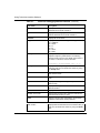
Preface
Before You Begin .............................................................................................................xix
Text Conventions ............................................................................................................. xx
Acronyms ........................................................................................................................xxii
Bay Networks Technical Publications .............................................................................xxv
How to Get Help ............................................................................................................xxvi
Chapter 1
Introducing the Technician Interface
Differences from Site Manager .......................................................................................1-2
Running the Technician Interface ...................................................................................1-3
Logging In ................................................................................................................1-3
User/Manager Login ..........................................................................................1-3
Login with Password ..........................................................................................1-4
Login with SecurID ............................................................................................1-4
Technician Interface Welcome Screen .............................................................1-10
Login Timeout Guidelines ................................................................................1-11
Login Configuration .........................................................................................1-12
Logging Out ............................................................................................................1-12
Starting a Manager Session from Within a User Session ......................................1-13
Using Technician Interface Scripts ................................................................................1-13
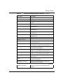
Chapter 2
Configuring the Console Port
Overview .........................................................................................................................2-2
Configuring Console Port Parameters ............................................................................2-2
Using the list Command ...........................................................................................2-3
Using the set Command ...........................................................................................2-3
Using the commit Command ....................................................................................2-4
Using the save Command ........................................................................................2-4
303561-A Rev 00
v
Console Port Parameters ...............................................................................................2-5
Using Autoscript Files ...................................................................................................2-19
Sample Autoscript Files .........................................................................................2-20
Customizing Autoscript Files ..................................................................................2-21
Chapter 3
Using Operating Commands
Overview .........................................................................................................................3-1
Displaying Online Help ...................................................................................................3-2
Pausing and Scrolling the Screen ...................................................................................3-2
Halting a Command ........................................................................................................3-3
Repeating the Command Last Entered ..........................................................................3-3
Repeating a Command Recently Entered ......................................................................3-4
Loading a Command into Memory .................................................................................3-6
Using the Ping Command ...............................................................................................3-7
IP Ping ......................................................................................................................3-8
IPv6 Ping ................................................................................................................3-11
IPX Ping .................................................................................................................3-14
OSI Ping .................................................................................................................3-17
VINES Ping ............................................................................................................3-20
AppleTalk Ping .......................................................................................................3-23
APPN Ping .............................................................................................................3-26
Displaying the ATM ARP Table for an Interface ............................................................3-29
Chapter 4
Managing a Nonvolatile File System
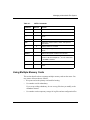
Overview .........................................................................................................................4-2
Using Multiple Memory Cards ........................................................................................4-3
Naming Files: Rules and Conventions ............................................................................4-5
Displaying the Status of All Memory Cards ....................................................................4-6
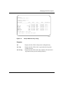
Displaying a Directory .....................................................................................................4-7
Changing the Active Volume .........................................................................................4-11
Copying a File ...............................................................................................................4-11
Copying Files from NVFS to DOS ................................................................................4-12
vi
303561-A Rev 00
Transferring a File .........................................................................................................4-13
In-Band File Transfers ............................................................................................4-14
Out-of-Band File Transfers .....................................................................................4-17
Displaying the Contents of a File ..................................................................................4-17
Deleting a File ...............................................................................................................4-18
Compacting File Space ................................................................................................4-19
Formatting a Memory Card ...........................................................................................4-20
Transferring a File to a Full Memory Card ....................................................................4-20
Partitioning a Memory Card or SIMM ...........................................................................4-21
Chapter 5
Managing a DOS File System
Overview .........................................................................................................................5-2
Naming Files and Directories .........................................................................................5-4
Mounting a Volume .........................................................................................................5-5
Unmounting a Volume ....................................................................................................5-7
Changing the Working Directory .....................................................................................5-7
Displaying a Directory .....................................................................................................5-8
Labeling a Diskette .......................................................................................................5-12
Creating a Directory .....................................................................................................5-12
Removing a Directory ...................................................................................................5-13
Renaming a File or Directory ........................................................................................5-14
Copying a File ...............................................................................................................5-15
Copying Files from DOS to NVFS ..........................................................................5-16
Transferring a File .........................................................................................................5-17
In-Band File Transfers ............................................................................................5-18
Out-of-Band File Transfers .....................................................................................5-20
Changing File Attributes ...............................................................................................5-20
Displaying the Contents of a File ..................................................................................5-22
Deleting a File ...............................................................................................................5-23
303561-A Rev 00
vii
Chapter 6
Managing Events
Overview .........................................................................................................................6-2
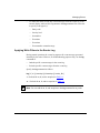
Logging and Displaying Event Messages .......................................................................6-2
Applying Write Filters to the Events Log ..................................................................6-3
Displaying Active Write Filters ..................................................................................6-5
Applying Read (Display) Filters to the Events Log ...................................................6-6
Saving the Events Log ....................................................................................................6-8
Saving the Events Log Automatically ............................................................................6-10
Log Autosave Platform Differences ........................................................................6-11
Configuring the Log Autosave Feature ...................................................................6-12
Displaying an Events Log File Previously Saved ..........................................................6-13
Clearing Events ............................................................................................................6-14
Chapter 7
Accessing the MIB
Listing MIB Objects .........................................................................................................7-2
Getting MIB Values .........................................................................................................7-4
Setting MIB Values .........................................................................................................7-6
Committing MIB Sets ......................................................................................................7-8
Saving the Configuration ................................................................................................7-9
Using the MIB-II Counter ................................................................................................7-9
Chapter 8
System Administration
Managing AN, ANH, ARN, and ASN Routers .................................................................8-2
Configuring the Boot Source ....................................................................................8-3
Configuring Initial Interfaces and Netboot Operation ...............................................8-5
Configuring the Initial IP Synchronous Interface ................................................8-5
Configuring an Ethernet Interface for Network Booting .....................................8-7
Enabling and Disabling Interfaces with ifconfig ..................................................8-8
Booting the Router ..........................................................................................................8-9
How the Router Boots ..............................................................................................8-9
Booting ...................................................................................................................8-10
Using the PCMCIA/Floppy Switch ..........................................................................8-12
Booting After Crossnet Shutdown Notification (BayStream Only) ..........................8-13
viii
303561-A Rev 00
Configuring Scheduled Boot Services ..........................................................................8-14
Adding Scheduled Boot Services to a Router ........................................................8-14
Scheduling Boot Events .........................................................................................8-15
Managing Scheduled Boot Services ......................................................................8-20
Disabling or Reenabling Scheduled Boot Services on a Router ......................8-20
Disabling or Reenabling a Scheduled Boot Event ...........................................8-20
Modifying Attributes for Scheduled Boot Events ..............................................8-21
Deleting Scheduled Boot Events .....................................................................8-21
Deleting Scheduled Boot Services from the Router ........................................8-21
Restarting a Slot ...........................................................................................................8-22
Restarting After Crossnet Shutdown Notification (BayStream Only) .....................8-23
Resetting a System or Slot ...........................................................................................8-24
Resetting After Crossnet Shutdown Notification (BayStream Only) .......................8-27
Running Diagnostics .....................................................................................................8-28
Enabling and Disabling Diagnostics During the Power-Up Sequence ...................8-31
AN and ANH Power-Up Diagnostic Option ......................................................8-31
ARN Diagnostics On/Off Option ......................................................................8-31
Turning Off the DIAG Indicator LED .......................................................................8-32
Displaying the Software Version ...................................................................................8-32
Halting Packet Transfer Between Slots .........................................................................8-33
Verifying and Upgrading Software ................................................................................8-33
Validating an Executable File ........................................................................................8-35
Upgrading and Verifying a PROM .................................................................................8-38
Upgrading PROMs Remotely .................................................................................8-39
Determining Current PROM Image Versions .........................................................8-39
Determining the Version of the Current Boot PROM Image ............................8-40
Determining the Version of the Current Diagnostics PROM Image .................8-40
Using the prom Command .....................................................................................8-41
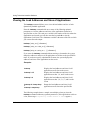
Viewing the Load Addresses and Sizes of Applications ...............................................8-44
Setting the ACE Backplane Type ..................................................................................8-46
Resetting the Date and Time ........................................................................................8-46
Configuring NTP Using the Technician Interface ..........................................................8-48
Assigning Passwords ....................................................................................................8-48
303561-A Rev 00
ix
Enabling and Disabling SecurID Authentication ...........................................................8-50
Enabling SecurID Authentication ............................................................................8-50
Disabling SecurID Authentication ...........................................................................8-52
Managing SNMP Secure Mode ....................................................................................8-53
Setting the Router to Operate in Secure Mode ......................................................8-54
Setting the Encryption Key .....................................................................................8-54
Resetting the Security Counter ..............................................................................8-55
Customizing Hardware Compression Search Depth ....................................................8-55
Testing Compression and Throughput ...................................................................8-56
WCP Search Depth Attributes ................................................................................8-57
Displaying a Greeting or Notice Before the Login Prompt ............................................8-59
Customizing the Technician Interface Welcome Message ............................................8-59
Recording Console Messages to a File ........................................................................8-60
Enabling Internal Clocking Mode ..................................................................................8-62
Responding to QENET Underflow Errors .....................................................................8-62
Monitoring IP Routes ....................................................................................................8-63
Specifying AS Path Search Patterns ......................................................................8-74
Routing Tables ........................................................................................................8-76
Interface Cache ......................................................................................................8-77
Multicast Cache ......................................................................................................8-78
Slot/Internal Cache ................................................................................................8-79
DVMRP Caches .....................................................................................................8-80
Viewing the Multicast Table Manager Forwarding Cache .......................................8-81
OSPF Link State Database ....................................................................................8-82
Determining Circuit Numbers .................................................................................8-83
Monitoring IPv6 Routes ................................................................................................8-85
Obtaining IPv6 Route and Node Information .........................................................8-86
Obtaining IPv6 Interface Statistics .........................................................................8-90
Setting Modem Initialization Strings .............................................................................8-91
Technician Interface Commands and Access Levels ....................................................8-92
x
303561-A Rev 00
Chapter 9
Managing Aliases
Creating and Displaying an Alias ....................................................................................9-2
Inserting Parameters in an Alias ..............................................................................9-3
Inserting Character Strings in an Alias .....................................................................9-5
Debugging Aliases ..........................................................................................................9-7
Deleting an Alias from Memory ......................................................................................9-7
Saving Aliases to a File ..................................................................................................9-8
Loading Aliases from a File ............................................................................................9-9
Debugging with Predefined Aliases ..............................................................................9-10
Appendix A
Using the Bay Networks Router MIB
Overview ........................................................................................................................ A-2
Bay Networks Router MIB Files ..................................................................................... A-7
Compliance with Specifications ..................................................................................... A-7
Implementation Notes .................................................................................................... A-8
MIB-II Object Definitions ......................................................................................... A-8
Supported Traps ...................................................................................................... A-9
Unsupported Operations ....................................................................................... A-10
Line Number Attributes ......................................................................................... A-10
Appendix B
Using Out-of-Band Access to Transfer Files
Overview ........................................................................................................................ B-1
About xmodem .............................................................................................................. B-2
The xmodem Command .......................................................................................... B-4
Command Parameters ...................................................................................... B-5
Command Options ............................................................................................ B-5
File Names ....................................................................................................... B-7
For More Information ............................................................................................... B-7
Implementation Notes .................................................................................................... B-7
File Handling ........................................................................................................... B-8
Error Checking ........................................................................................................ B-8
Canceling a File Transfer ......................................................................................... B-8
Modem Interface Differences .................................................................................. B-8
Viewing xmodem Log Events .................................................................................. B-9
303561-A Rev 00
xi
Hardware Configuration ................................................................................................. B-9
Out-of-Band File Transfers from a UNIX Workstation .................................................. B-10
Opening a Connection .......................................................................................... B-10
Transferring Files from a Router to a UNIX Workstation ....................................... B-10
Transferring Files from a UNIX Workstation to a Router ....................................... B-13
Out-of-Band File Transfers from a Windows Workstation ............................................ B-17
xmodem and the Bay Networks Communications Terminal Program ................... B-17
Opening Wfterm .................................................................................................... B-18
Checking and Verifying Current Modem Interface Settings ............................ B-19
Initializing the Local Modem .................................................................................. B-21
Using Wfterm Telephone Call Functions ............................................................... B-22
Dialing a Remote Router ....................................................................................... B-22
Logging In to the Router’s Technician Interface .................................................... B-24
File Transfer Functions .......................................................................................... B-24
Transferring Files from a Router to a DOS Workstation ........................................ B-25
Transferring Files from a DOS Workstation to a Router ........................................ B-28
Closing the Connection ......................................................................................... B-30
Quitting Wfterm ..................................................................................................... B-31
Appendix C
Using Syslog Messaging to
Monitor Router Events
Overview ........................................................................................................................ C-1
Remote Hosts and Filters ........................................................................................ C-4
Polling the Events Log ............................................................................................. C-5
Identifying Entity Filters ........................................................................................... C-5
Filtering by Event Number ....................................................................................... C-6
Filtering by Event Severity Level ............................................................................. C-7
Filtering by Slot Number .......................................................................................... C-7
Mapping Router Event Messages into Syslog Message Format ............................ C-8
IP Header ......................................................................................................... C-9
UDP Header ................................................................................................... C-10
UDP Data ....................................................................................................... C-10
Priority Code ................................................................................................... C-10
Time Sequencing Syslog Messages ..................................................................... C-12
Syslog Message Handling on a Workstation ......................................................... C-12
xii
303561-A Rev 00
Configuring Syslogd on a UNIX Workstation ............................................................... C-13
Configuring Syslog on the Router ................................................................................ C-15
Task 1: Logging In to the Router’s Technician Interface ........................................ C-15
Task 2: Defining a Slot Mask for Syslog on the Router ......................................... C-16
Task 3: Creating Syslog on the Router .................................................................. C-16
Task 4: Configuring Syslog Global Attributes ........................................................ C-16
Task 5: Adding a Remote Host to the Syslog Host Table ...................................... C-17
Task 6: Adding an Entity Filter for a Remote Host ................................................. C-19
Task 7: Adding More Hosts or Entity Filters .......................................................... C-22
Task 8: Saving Your Syslog Configuration on the Router ...................................... C-22
Task 9: Logging Out of the Technician Interface ................................................... C-22
Managing Syslog on a Router ..................................................................................... C-23
Disabling or Reenabling Syslog on the Router ...................................................... C-23
Disabling or Reenabling Syslog Hosts or Filters ................................................... C-24
Deleting Remote Hosts or Entity Filters from the Syslog Configuration ................ C-25
Deleting Syslog from the Router ........................................................................... C-25
Example Syslog Configuration .............................................................................. C-26
Syslog Parameter Descriptions ................................................................................... C-28
Global/Group Parameters ..................................................................................... C-30
Host Parameters ................................................................................................... C-33
Entity Filter Parameters ......................................................................................... C-38
For More Information ................................................................................................... C-48
Index
303561-A Rev 00
xiii
Figures
Figure 1-1.
SecurID Login Procedure and Interface Dialog .......................................1-8
Figure 1-2.
SecurID PIN Assignment Procedure and Interface Dialog ......................1-9
Figure 1-3.
Technician Interface Welcome Screen ...................................................1-10
Figure 4-1.
Sample Dinfo Display ...............................................................................4-6
Figure 4-2.
Sample NVFS Directory Listing ...............................................................4-8
Figure 5-1.
Mounting a Volume ..................................................................................5-5
Figure 5-2.
Sample DOS Directory Listing .................................................................5-9
Figure 8-1.
RUIBOOT Date and Time Entry .............................................................8-16
Figure 8-2.
RUIBOOT Date and Time Example .......................................................8-18
Figure 8-3.
Sample Response to readexe Command ..............................................8-36
Figure A-1.
Sample Top-Level Hierarchy of the Bay Networks Router MIB
(continued) .............................................................................................. A-3
Figure A-1.
Sample Top-Level Hierarchy of the Bay Networks Router MIB
(continued) .............................................................................................. A-4
Figure A-1.
Sample Top-Level Hierarchy of the Bay Networks Router MIB
(continued) .............................................................................................. A-5
Figure A-1.
Sample Top-Level Hierarchy of Bay Networks Router MIB Objects ........ A-6
Figure B-1.
Modem Connection ................................................................................. B-9
Figure B-2.
Wfterm Icon .......................................................................................... B-18
Figure B-3.
The Wfterm Base Program Window ..................................................... B-18
Figure B-4.
Accessing the Modem Settings Window ............................................... B-20
Figure B-5.
Verifying or Modifying Modem Interface Settings .................................. B-20
Figure B-6.
Verifying Successful Modem Initialization ............................................. B-21
Figure B-7.
Accessing Wfterm Telephone Call Functions ........................................ B-22
Figure B-8.
Wfterm Dial Command Window ............................................................ B-23
Figure B-9.
Wfterm File Transfer Operation Selection Window ............................... B-25
Figure B-10. Wfterm File to Transfer Window ............................................................ B-27
Figure B-11. Wfterm Connection Closed Window ..................................................... B-30
Figure B-12. Exiting/Quitting the Wfterm Program .................................................... B-31
303561-A Rev 00
xv
Figure C-1.
Syslog and Syslogd Operations .............................................................. C-3
Figure C-2.
Router Event Message Filtering for One Host ........................................ C-5
Figure C-3.
Syslog Message Encapsulation .............................................................. C-9
Figure C-4.
Syslog Message Composition ............................................................... C-10
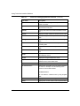
Tables
Table 4-1.
NVFS Commands ....................................................................................4-3
Table 4-2.
Router Software Images ..........................................................................4-4
Table 5-1.
DOS File Management Commands ........................................................5-3
Table 5-2.
DOS File Attributes ................................................................................5-11
Table 5-3.
DOS File Attributes
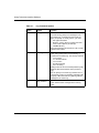
Table 6-1.
Log Command Options ............................................................................6-4
Table 8-1.
Options for the bconfig Command
Table 8-2.
Options for the ifconfig Command ..........................................................8-6
Table 8-3.
Settings for the ifconfig Command (Ethernet Interface) ..........................8-7
Table 8-4.
Router Reset Commands and Respones
Table 8-5.
Router Diagnostic Commands and Respones .....................................8-30
Table 8-6.
IP Subcommand Meanings ....................................................................8-64
Table 8-7.
Flag Descriptions .................................................................................8-65
Table 8-8.
Simplified AS Pattern Matching Syntax ................................................8-74
Table 8-9.
Simplified AS Pattern Matching Examples ............................................8-75
Table 8-10.
Protocol Letters and Meanings ..............................................................8-81
Table 8-11.
IP Subcommand Meanings ....................................................................8-85
Table 8-12.
Options for ip6 routes Command ..........................................................8-86
..............................................................................5-20
.........................................................8-4
............................................8-26
Table 8-13.
Technician Interface Access Levels
Table 9-1.
Aliases for Debugging Network Problems ............................................9-10
Table B-1.
Option Flags for the Xmodem Command ............................................... B-6
Table C-1.
Syslogd Error Levels ........................................................................... C-45
303561-A Rev 00
.....................................................8-92
xvii
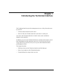
Preface
The Technician Interface is a command-line interface that lets you manage Bay
Networks routers. You can use the Technician Interface to install a router,
maintain or diagnose router operation, and monitor and configure certain basic
router functions.
Before You Begin
If you are responsible for installing or maintaining a Bay Networks® router or
BayStream™ platform using Bay Networks Technician Interface commands, you
need to read this guide.
Before using this guide to issue Technician Interface commands, you must
complete the following procedures:
•
Install the hardware platform.
•
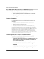
Use one of the following methods to establish a connection to the platform:
-- Connect the serial port of an ASCII terminal device (for example, a DEC
VT100) directly to the console port of the platform.
-- Connect the serial port of a workstation or PC directly to the console port
of the platform. (Run ASCII terminal emulation software on the
workstation or PC.)
-- Dial in to the console port of the platform from a workstation or PC
running ASCII terminal emulation software. This alternative requires one
modem locally attached to your workstation or PC, and another modem
locally attached to the console port of the platform you want to access.
-- Establish a Telnet (in-band) connection to the platform.
303561-A Rev 00
xix
Using Technician Interface Software
Note: Before you can access the Technician Interface using Telnet, the
platform must have at least one assigned IP address. Although there is no limit
to the number of Telnet connections that you can make to the Technician
Interface, we recommend that you establish no more than one Telnet session
per platform.
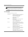
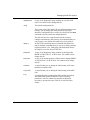
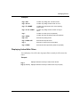
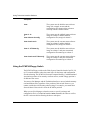
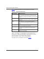
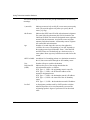
Text Conventions
This guide uses the following text conventions:
angle brackets (< >)
Indicate that you choose the text to enter based on the
description inside the brackets. Do not type the
brackets when entering the command.
Example: If the command syntax is:
ping <ip_address>, you enter:
ping 192.32.10.12
bold text
Indicates text that you need to enter and command
names and options.
Example: Enter show ip {alerts | routes}
Example: Use the dinfo command.
braces ({})
Indicate required elements in syntax descriptions
where there is more than one option. You must choose
only one of the options. Do not type the braces when
entering the command.
Example: If the command syntax is:
show ip {alerts | routes}, you must enter either:
show ip alerts or show ip routes.
brackets ([ ])
Indicate optional elements in syntax descriptions. Do
not type the brackets when entering the command.
Example: If the command syntax is:
show ip interfaces [-alerts], you can enter either:
show ip interfaces or show ip interfaces -alerts.
xx
303561-A Rev 00
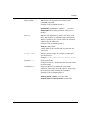
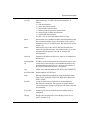
Preface
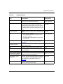
ellipsis points (. . . )
Indicate that you repeat the last element of the
command as needed.
Example: If the command syntax is:
ethernet/2/1 [<parameter> <value>] . . ., you enter
ethernet/2/1 and as many parameter-value pairs as
needed.
italic text
Indicates file and directory names, new terms, book
titles, and variables in command syntax descriptions.
Where a variable is two or more words, the words are
connected by an underscore.
Example: If the command syntax is:
show at <valid_route>
<valid_route> is one variable and you substitute one
value for it.
screen text
Indicates system output, for example, prompts and
system messages.
Example: Set Bay Networks Trap Monitor Filters
separator ( > )
Shows menu paths.
Example: Protocols > IP identifies the IP option on the
Protocols menu.
vertical line ( | )
Separates choices for command keywords and
arguments. Enter only one of the choices. Do not type
the vertical line when entering the command.
Example: If the command syntax is:
show ip {alerts | routes}, you enter either:
show ip alerts or show ip routes, but not both.
303561-A Rev 00
xxi
Using Technician Interface Software
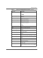
Acronyms
xxii
ACE
advanced communications engine
APPN
Advanced Peer-to-Peer Networking
ARP
Address Resolution Protocol
AT
Appletalk
ATM
asynchronous transfer mode
AURP
Appletalk Update-based Routing Protocol
BGP
Border Gateway Protocol
BootP
Bootstrap Protocol
CLNP
Connectionless Network Protocol
CPU
central processing unit
CRC
cyclic redundancy check
CSMA/CD
carrier sense multiple access with collision detection
DCM
Data Collection Module
DLCMI
Data Link Control Management Interface
DLSw
data link switching
DOS
Disk Operating System
DRAM
dynamic random access memory
DSAP
destination service access point
DVMRP
Distance Vector Multicast Routing Protocol
EOF
end of file
EGP
Exterior Gateway Protocol
FAT
file allocation table
FDDI
Fiber Distributed Data Interface
FIFO
first in first out
FR
frame relay
FRSW
frame relay switch
303561-A Rev 00
Preface
303561-A Rev 00
FTP
File Transfer Protocol
GAME
Gate Access Management Entity
GMT
Greenwich mean time
HDLC
high-level data link control
HSSI
High-Speed Serial Interface
ICMP
Internet Control Message Protocol
IGMP
Internet Group Membership Protocol
IP
Internet Protocol
IPX
Internet Packet Exchange Protocol
ISDN
Integrated Services Digital Network
ISO
International Organization for Standardization
LAN
local area network
LAP-B
Link Access Procedure-Balanced
LED
light emitting diode
LLC
Logical Link Control Protocol
LMI
local management interface
LNM
LAN Network Manager
LSP
link state packet
MAC
media access control
MCT1
Multichannel T1
MIB
management information base
MOSY
managed object syntax
NML
Native Mode LAN Protocol
NSAP
network service access point
NVFS
nonvolatile file system
OSI
Open Systems Interconnection
OSPF
Open Shortest Path First (Protocol)
PCMCIA
Personal Computer Memory Card International
Association
xxiii
Using Technician Interface Software
xxiv
PIN
personal identification number
PPP
Point-to-Point Protocol
PPX
parallel packet exchange
PROM
programmable read-only memory
QENET
Quad Ethernet
RAM
random access memory
RARP
Reverse Address Resolution Protocol
RIF
routing information field
RFC
Request for Comment
SAP
service access point
SDLC
Synchronous Data Link Control
SIMM
single inline memory module
SMDS
switched multimegabit data service
SNAP
SubNetwork Access Protocol
SNMP
Simple Network Management Protocol
SR
source routing
SRM-L
System Resources Module - Link
STA
statistics, thresholds, and alarms
STP
shielded twisted-pair
SWS
switched services
SYNC
synchronous
SYSCON
system controller board
TCP
Transmission Control Protocol
TCP/IP
Transmission Control Protocol/Internet Protocol
Telnet
Telecommunication Network
TFTP
Trivial File Transfer Protocol
TIP
Terminal Interface Program
TP
Transaction Program
VC
virtual circuit
303561-A Rev 00
Preface
VINES
Virtual Network Systems
WAN
wide area network
XB
translation bridge
XNS
Xerox Networking Systems
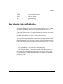
Bay Networks Technical Publications
You can now print Bay Networks technical manuals and release notes free,
directly from the Internet. Go to support.baynetworks.com/library/tpubs/. Find the
Bay Networks product for which you need documentation. Then locate the
specific category and model or version for your hardware or software product.
Using Adobe Acrobat Reader, you can open the manuals and release notes, search
for the sections you need, and print them on most standard printers. You can
download Acrobat Reader free from the Adobe Systems Web site,
www.adobe.com.
You can purchase Bay Networks documentation sets, CDs, and selected technical
publications through the Bay Networks Collateral Catalog. The catalog is located
on the World Wide Web at support.baynetworks.com/catalog.html and is divided
into sections arranged alphabetically:
•
The “CD ROMs” section lists available CDs.
•
The “Guides/Books” section lists books on technical topics.
•
The “Technical Manuals” section lists available printed documentation sets.
Make a note of the part numbers and prices of the items that you want to order.
Use the “Marketing Collateral Catalog description” link to place an order and to
print the order form.
303561-A Rev 00
xxv
Using Technician Interface Software
How to Get Help
For product assistance, support contracts, or information about educational
services, go to the following URL:
http://www.baynetworks.com/corporate/contacts/
Or telephone the Bay Networks Technical Solutions Center at:
800-2LANWAN
xxvi
303561-A Rev 00
Chapter 1
Introducing the Technician Interface
The Technician Interface provides management access to a Bay Networks router
by means of:
•
Telnet (in-band) connection to the router
•
Direct or dial (out-of-band) connection to the router’s console port
You can use the Technician Interface to install a router, and to maintain or
diagnose router operation.
In addition, you can use the Technician Interface to monitor and configure certain
basic functionality in a Bay Networks router. See Using Technician Interface
Scripts and Writing Technician Interface Scripts for more information about
performing these tasks.
This chapter describes:
303561-A Rev 00
•
Differences between the Technician Interface and Site Manager
•
How to log in and out of the Technician Interface
•
Technician Interface scripts (brief overview)
1-1
Using Technician Interface Software
Differences from Site Manager
The Technician Interface running on the router, and the Site Manager application
running on a PC or UNIX workstation, both manage the router software. The
Technician Interface differs from Site Manager as follows:
•
The Technician Interface resides in the router’s operating system kernel and
automatically loads when you boot the router. You do not need to install the
Technician Interface software from a separate medium first; all you need is an
ASCII terminal or Telnet connection to the router. Site Manager, however,
resides on a workstation and runs independently of the router software.
•
You establish a Technician Interface session through the router’s console port,
using a local ASCII terminal or dial-up connection. You establish a Site
Manager session independently and establish an in-band connection over the
network.
•
The Technician Interface scripts let you display information about various
protocols and network services and enable or disable protocols, circuits, lines,
and services.
•
The Technician Interface is a command-line interface; it assumes that you are
a network manager who knows the Technician Interface command syntax, the
MIB, and SNMP. (The Technician Interface does provide online Help,
however.)
In contrast, Site Manager is menu driven: when you display screens and select
options from Site Manager menus, it automatically sends the appropriate
SNMP commands to the router. Site Manager also provides help text.
Caution: The Technician Interface does not provide the consistency checking
or verification that the Site Manager static configuration feature provides.
Technician Interface users can set erroneous values, commit the values to
memory, and save the values to configuration files, thereby possibly disrupting
router functionality and network activity.
1-2
303561-A Rev 00
Introducing the Technician Interface
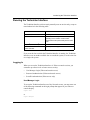
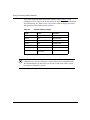
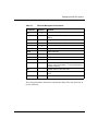
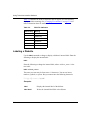
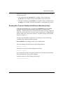
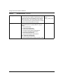
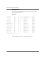
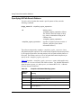
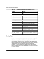
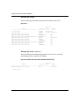
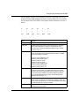
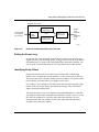
Running the Technician Interface
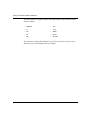
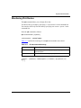
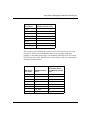
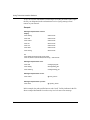
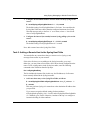
The Technician Interface software entity normally runs on one slot only, except as
noted otherwise in the following table:
Router Model
Slot
AN®, ANH™, ARN™
Slot 1 only
ASN
Slots 1 to 4, individually or simultaneously,
depending on the number of ASN routers
stacked and the setup of the back panel for each
router
BN (BLN®, BLN-2, BCN®)
Slot 2
™
LN® or CN® with SYSCON-II flash Any slot (one slot only)
system controller
If you reset the slot on which the Technician Interface is running, the Technician
Interface resets to another available slot on a multislot system, or to the same slot
on a single-slot system.
Logging In
When you access the Technician Interface via Telnet or console session, you
encounter up to three levels of router access security:
•
User/Manager Login (Telnet and console access)
•
Password Authentication (Telnet and console access)
•
SecurID Authentication (Telnet access only)
User/Manager Login
To access the Technician Interface on a Bay Networks router, you must enter one
of the following commands at the login prompt that appears in your Telnet or
console display:
Login: User
or
Login: Manager
303561-A Rev 00
1-3
Using Technician Interface Software
Note: You must press the return key after every Technician Interface
command. Technician Interface commands and passwords are case-sensitive.
Use upper- and lowercase as indicated.
The User login entry allows you to enter read-only commands. These only read
information from the router.
The Manager login entry allows you to enter any Technician Interface commands.
Certain commands read information from the router and/or write information to
the router.
We recommend limiting Manager access to network managers and the Bay
Networks Technical Solutions Center. The section “Technician Interface
Commands and Access Levels” in Chapter 8 lists all of the Technician Interface
commands and their associated access requirements.
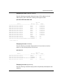
Login with Password
If you enable password authentication on a router, you must also enter a password
after the Password prompt that appears following your login entry.
Login:
<User | Manager>
Password:
<password>
New routers initially have no password login requirements. If your network
administrator enables password access on a router, the Password prompt appears
when you attempt a login to that router. We recommend password access to help
establish access and data security for routers in your network. For instructions on
how to enable or disable password authentication on a router, see “Assigning
Passwords” in Chapter 8.
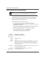
Login with SecurID
SecurID is a feature for barring unauthorized users from accessing the Technician
Interface on a Bay Networks router through a Telnet session.
1-4
303561-A Rev 00
Introducing the Technician Interface
If you enable this feature on a router, you enter in addition to a login entry a
SecurID PASSCODE™ after the Passcode prompt, as follows:
Login:
<User | Manager>
Password:
Passcode:
<password> (if enabled)
<passcode>
If your SecurID administrator enables the SecurID client on a router you need to
access, you see the Passcode prompt at login time. When you enter a valid
PASSCODE, you receive Technician Interface login privileges to the router. You
receive on your Telnet access screen the Technician Interface login prompt, $: (or
whatever your network administrator selects for the Telnet login prompt).
Each User or Manager authorized to access a router configured with an active
SecurID client must have an electronic SecurID card issued by Security
Dynamics, Inc. Security Dynamics programs each card with a personal
identification number (PIN) to uniquely identify its prospective owner, and then
assigns the card for exclusive use by that person only.
If you do not have an assigned PIN, the SecurID client on the router also prompts
you through a routine for PIN assignment. (The SecurID administrator for your
network must first configure the ID system to allow you to access the PIN
assignment feature.) The SecurID administrator can enable you either to select
your own PIN, or to accept a system-generated PIN.
The SecurID card uses an internal algorithm to electronically generate temporary
“cardcodes.” Before allowing you to access the Technician Interface of a router,
the SecurID client requires you to enter your PIN, followed by the current
cardcode from your SecurID card.
The SecurID server on your network either:
303561-A Rev 00
•
Recognizes your PASSCODE and grants access to the router’s Technician
Interface
•
Does not recognize your PASSCODE and denies access to the router’s
Technician Interface
1-5
Using Technician Interface Software
Note: If the SecurID system denies you access to a router after four login
attempts, the system then removes your PIN from the current list of valid
SecurID users. To reactivate your SecurID PIN, you must request reactivation
from the SecurID administrator of your network.
Newly installed routers initially do not require SecurID authentication for
Technician Interface login privileges. (The network administrator must first enable
the feature on the router.)
We recommend SecurID authentication for routers that require the highest level of
protection from unauthorized Telnet access to the Technician Interface. To support
Technician Interface login via SecurID, you must have a Security Dynamics
SecurID ACE® server system installed on your IP network. Routers with the
SecurID ACE client enabled communicate with the SecurID server during each
user authentication sequence.
For more information about SecurID server systems, contact your Bay Networks
sales representative.
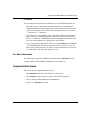
SecurID Login and PIN Assignment Dialog
This section describes more fully the interface dialog you may encounter when
attempting a login to a router configured with SecurID client software. Normally
you can open a Technician Interface session as long as you enter a valid
PASSCODE (your PIN, followed by the current cardcode). If you do not have a
valid SecurID PIN when you attempt the login, you may receive another series of
prompts for automated PIN assignment.
Note: The SecurID administrator for your network must first configure the
SecurID system to allow you to receive a PIN through the SecurID client
software on the router.
1-6
303561-A Rev 00
Introducing the Technician Interface
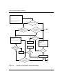
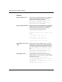
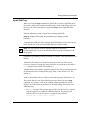
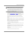
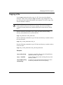
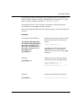
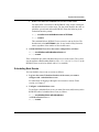
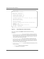
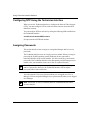
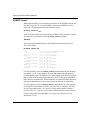
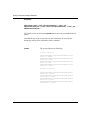
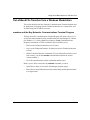
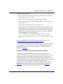
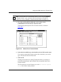
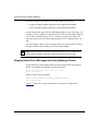
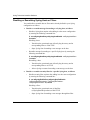
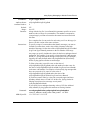
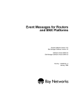
Figure 1-1 shows the complete authentication procedure and interface dialog you
may encounter when attempting a login to a router configured with SecurID client
software. Whenever you enter information that the SecurID client considers
incorrect, you receive more prompts until you log in successfully, or until the
SecurID client denies you further access to the router.
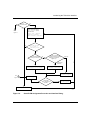
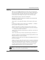
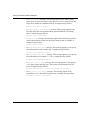
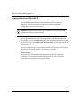
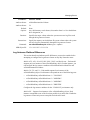
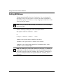
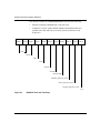
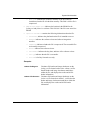
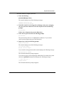
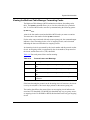
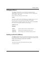
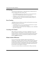
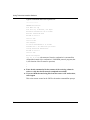
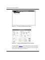
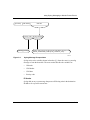
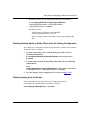
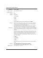
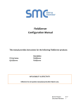
Figure 1-2 shows the complete new PIN assignment procedure and interface
dialog you encounter during your initial login attempt, if you do not already have
a valid assigned SecurID PIN.
To configure the SecurID client software on the router, see “Enabling and
Disabling SecurID Authentication” in Chapter 8.
303561-A Rev 00
1-7
Using Technician Interface Software
Open a Telnet connection
to the router:
>telnet
<router_name>
Trying <router_ip_address>.
Connected to <router_name>
Escape character is '^]".
yes
SecurID authentication
enabled on the router?
no
BEGIN HERE
yes
Is your card in
"Set PIN to next
cardcode" mode?
no
yes
Your first login
attempt using SecurID
authentication?
See
A
Figure 1-2
no
yes
Enter a passcode after the
Enter Passcode prompt
from the router:
Login: <User | Manager>
Password: <password>
Enter Passcode: <passcode>
Fourth login
attempt?
Access denied,
password bad.
Enter only your Login
level (User/Manager)
and (if enabled) enter
a password:
Login: <User | Manager>
Password: <password>
no
Fourth attempt to
authenticate?
no
Access denied,
cardcode bad.
yes
no
Enter next
cardcode:
Valid
cardcode?
no
Valid
password?
yes
yes
Login privileges granted
no
PIN accepted by the
SecurID server?
yes
B
From
Figure 1-2
TS0007B
Figure 1-1.
1-8
SecurID Login Procedure and Interface Dialog
303561-A Rev 00
Introducing the Technician Interface
Card is in
"new PIN" mode?
no
A
yes
Enter a passcode after the
Enter Passcode prompt
from the router:
From
Figure 1-1
Login: <User | Manager>
Password: <password>
Enter Passcode: <cardcode>
no
New PIN required.
Do you wish to
continue?(yes/no):
yes
Are you authorized
to select your own PIN?
yes
System configured to
generate new PINs containing
alphanumeric characters
or digits only?
no
digits only
alphanumeric
characters
<Return> to generate a new PIN
and display it on the screen:
Enter your new PIN
containing x characters:
Enter your new PIN
containing x digits:
Go to
B
New PIN accepted
Figure 1-1
yes
The SecurID
Server accepted your
new PIN?
New PIN rejected
no
New PIN protocol aborted
TS0008A
Figure 1-2.
303561-A Rev 00
SecurID PIN Assignment Procedure and Interface Dialog
1-9
Using Technician Interface Software
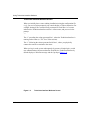
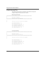
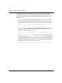
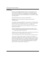
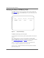
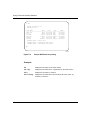
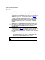
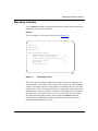
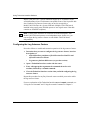
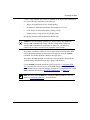
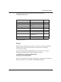
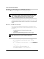
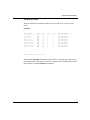
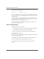
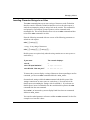
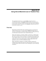
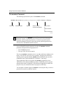
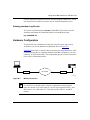
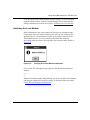
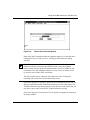
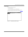
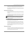
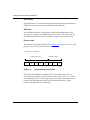
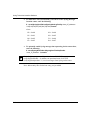
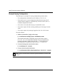
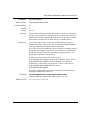
Technician Interface Welcome Screen
When you initially boot a router (during installation) using the configuration file
ti.cfg, you receive login prompt on your console display or Telnet connection. For
example, booting from a console locally connected to Serial Port 1 of a router
initializes the Technician Interface on Slot 1 of that router, and you receive the
prompt:
1:1
The “1” preceding the colon represents Slot 1, where the Technician Interface is
running on the router (or “TN” for a Telnet session).
The “1” following the colon represents Serial Port 1, where you physically
connect the console or terminal to the router.
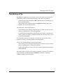
When you log in to the system subsequently (by means of simple login, or with
user authentication with password and/or SecurID), the Technician Interface by
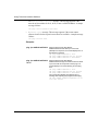
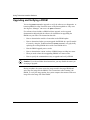
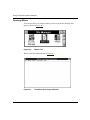
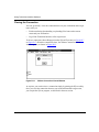
default displays a Welcome message and the $ prompt (Figure 1-3).
Figure 1-3.
1-10
Technician Interface Welcome Screen
303561-A Rev 00
Introducing the Technician Interface
Your network administrator can change the Technician Interface prompt you
receive on a local or remote ASCII console or Telnet connection screen. For
instructions on how to change the Technician Interface login prompt you receive
on a local or remote ASCII terminal or console screen, see Chapter 2. For
instructions on how to change the Technician Interface login prompt you receive
on a remote Telnet screen, see Configuring TCP Services.
You enter Technician Interface commands after the colon (:) prompt, the dollar
sign ($) prompt, or whatever prompt your network administrator sets on the router
for console or Telnet access to the router.
You can also customize the Technician Interface Welcome screen with a message
appropriate for the requirements of your organization or network site. See
“Customizing the Technician Interface Welcome Message” in Chapter 8 for
instructions.
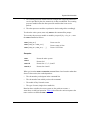
Login Timeout Guidelines
Keep the following in mind when you enter your login name (User or Manager)
and password:
303561-A Rev 00
•
If you do not make an entry at the Login prompt for 1 minute (default), the
Technician Interface disconnects from the router.
•
If you do not make an entry at the Password prompt for 1 minute (default), the
Technician Interface returns you to the Login prompt.
•
If you enter your login name or password incorrectly three times (default), the
Technician Interface disconnects you from the router.
•
If you do not make an entry at the SecurID prompt for 1 minute (default), the
Technician Interface returns you to the Login prompt.
•
If you enter the SecurID PASSCODE incorrectly four times (default), the
SecurID client software disconnects you from the router and initiates
deactivation of your SecurID card account. You must request reactivation
from the SecurID administrator for your network.
1-11
Using Technician Interface Software
Login Configuration
For instructions on changing the default values associated with the console port,
see “Configuring Console Port Parameters” in Chapter 2.
For instructions on changing the default values associated with Telnet access to
the Technician Interface, see Configuring IP Utilities.
For information about changing the default values associated with SecurID
services, see “Enabling and Disabling SecurID Authentication” in Chapter 8.
Logging Out
To exit a Technician Interface session, enter the following command after the
Technician Interface prompt:
logout
For a console connected directly to the router, the Login prompt reappears:
Login:
<User | Manager>
Password:
Passcode:
<password> (if enabled)
<passcode> (if enabled)
For a remote terminal program on a PC or workstation connected to the router by
means of modems, the following messages appear, and the Technician Interface
hangs up the telephone:
TI session logged out.
** Goodbye. **
Note: To use the Technician Interface with a modem, see Chapter 2.
If the Modem Enable parameter has a setting of Disable (default) and the session
terminates unexpectedly, the router does not automatically log you out. You must
reestablish a connection to the router and log out using the logout command.
1-12
303561-A Rev 00
Introducing the Technician Interface
Starting a Manager Session from Within a User Session
You can initiate a Manager session within a User session by entering the following
command:
system
The Password prompt appears at this time if your network administrator
configured a password for Manager access. Enter the password after the prompt.
The Technician Interface prompt appears when the system logs you in.
Enter logout to terminate the Manager session. You return to the User session
when the Technician Interface prompt reappears.
Using Technician Interface Scripts
The Technician Interface scripts are programs that let you manage the router using
information stored in the management information base (MIB). You can use the
scripts to display information about protocols and network services and to enable
or disable protocols, circuits, lines, and services.
You access the Technician Interface scripts using the following commands:
•
show displays system configuration, state, and statistical information. This
command helps you isolate problems such as circuits that are not working,
packets that are not being forwarded, and so on.
•
monitor displays the same information as the show command but refreshes
the display periodically so you can examine trends and changes.
•
enable/disable enables or disables system features, protocols, drivers, or
individual circuits.
•
menu provides a menu interface to the other scripts. You can also use the
menu-building features of this script to create custom menus.
A number of Technician Interface scripts exist as programs embedded within the
router software image, rather than as individually loadable batch files (file name
<entity_name>.bat). You run the embedded and batch file versions of scripts in
an identical manner, using the script commands described in Using Technician
Interface Scripts. The embedded scripts run more efficiently than scripts based on
loadable batch files.
303561-A Rev 00
1-13
Using Technician Interface Software
The router software currently includes embedded scripts for the following router
software entities:
•
CSMACD
•
TCP
•
IP
•
TFTP
•
IPX
•
SNMP
•
FR
•
SYNC
•
FTP
•
TELNET
You can also use menus (described in Using Technician Interface Scripts) as an
alternative way of accessing the full set of scripts.
1-14
303561-A Rev 00
Chapter 2
Configuring the Console Port
To configure a router’s console port parameters using the Technician Interface,
you have to change the default parameter settings associated with the console port
on the back of the router. You can change the default parameter settings for the
console port associated with the following boards:
•
System Resources Link Module (SRM-L) board found in the BLN, BLN-2,
and BCN routers
•
System Input/Output (SYS I/O) board found in the FN™, LN, CN, and ALN
routers
•
Primary processor board found in the AFN®, AN, and ASN routers
•
Base module found in ARN routers
The autoscript feature allows you to automatically execute certain Technician
Interface commands when you log in as either a Manager or User.
Note: You can use the console port to connect either a console or modem to
the router.
303561-A Rev 00
2-1
Using Technician Interface Software
Overview
You access the Technician Interface software through a console or modem
attached to a router serial port. The number of Technician Interface sessions you
can establish for a router depends on the number of serial ports available on that
router.
•
The SRM-L board has one serial port (labeled “Console”), allowing you to
establish one session on a Backbone Node platform.
•
The SYS I/O board has three serial ports (labeled “Console,” “Modem 1” and
“Modem 2”), allowing you to establish up to three sessions on a VME
platform.
•
The AFN processor board has two serial ports (labeled “Console” and
“Modem”), allowing you to establish one or two sessions.
•
The AN processor board has one serial port (labeled “Console”), allowing you
to establish one session.
•
The ARN base module has up to three serial ports (one labeled “Console,”
one labeled “Modem,” and an optional V.34 modem interface), allowing you
to establish one session.
•
The ASN base board has one serial port per router, with up to four routers
stacked, allowing you to establish up to four sessions with the interconnected
stack.
See Configuring Routers if you prefer to user Site Manager to configure the serial
port parameters for the router console.
Configuring Console Port Parameters
The following sections describe how to use the following Technician Interface
commands:
2-2
•
list
•
set
•
commit
•
save
303561-A Rev 00
Configuring the Console Port
Using the list Command
You can list and review all serial port attributes by entering the following
command line at the Technician Interface prompt:
list wfSerialPortEntry
Using the set Command
Enter one of the following Technician Interface commands to configure a console
port parameter:
set wfSerialPort Entry.<attribute_name>.<port_no.> <option>
set wfSerialPort Entry.<attribute_no.>.<port_no.> <option>
303561-A Rev 00
set
Refers to the Technician Interface set command. You
must have Manager access to issue a set command.
wfSerialPortEntry
Refers to the MIB attribute name associated with all
serial port parameters.
<attribute_name>
Is the MIB attribute name associated with one of the
serial port parameters.
<attribute_no.>
Is the MIB attribute number associated with one of
the serial port parameters.
<port_no.>
Is the number of the serial port you are configuring.
<option>
Is the new setting taken from the Options list.
2-3
Using Technician Interface Software
Example:
The following commands set the Parity parameter to Odd:
set wfSerialPortEntry.wfSerialPortParity.1 2
or
set wfSerialPortEntry.10.1 2
Note: You can use s instead of set.
Using the commit Command
Enter the following command after issuing one or more set commands:
commit
The commit command causes the changes you made to the configuration to take
effect in active memory, but not in flash memory. You must use the save
command subsequently to save changes to a configuration file (config) and flash
volume on the router.
The Technician Interface software service resets when you enter the commit
command.
Using the save Command
After you set and commit changes to the current configuration running in active
memory on the router, use the save command to store that configuration to a file
on a flash memory volume, as follows:
save config <vol>:<filename>
Note: You can also use the save command to save the current contents of the
router’s event log, environment variable list, or alias list. See Chapters 6, 7, and
9 for more information about these applications of the save command.
2-4
303561-A Rev 00
Configuring the Console Port
Console Port Parameters
This section describes parameters for configuring the serial (console) port on the
router. Each parameter description includes the following:
•
Parameter
•
Attribute name
•
Attribute number
•
Bay Networks default setting
•
Options or range of valid settings
•
Parameter’s function
•
Instructions for setting the parameter
•
Command you enter to configure or monitor the parameter
•
MIB object ID
Note: You cannot configure the following console port parameters: State,
Number, Name, and Slot.
Parameter:
Attribute Name:
Attribute Number:
Port Delete
wfSerialPortDelete
1
Default:
1 (Create)
Options:
1 (Create) | 2 (Delete)
Function:
Instructions:
Command:
MIB Object ID:
303561-A Rev 00
Creates or deletes an instance of a console port.
Set to 1 (Create) to create a MIB record with system defaults for a console
port. Set to 2 (Delete) to delete a MIB record for a console port.
set wfSerialPortEntry.1.<port_no.> <option>
1.3.6.1.4.1.18.3.3.2.11.1.1.1
2-5
Using Technician Interface Software
Parameter:
Attribute Name:
Attribute Number:
Port Disable
wfSerialPortDisable
2
Default:
1 (Enable)
Options:
1 (Enable) | 2 (Disable)
Function:
Enables or disables the console port.
Instructions:
Select the status of the console port.
Command:
MIB Object ID:
Parameter:
Attribute Name:
Attribute Number:
set wfSerialPortEntry.2.<port_no.> <option>
1.3.6.1.4.1.18.3.3.2.11.1.1.2
Port State
wfSerialPortState
3
Default:
4 (Not present)
Options:
1 (Up) | 2 (Down) | 3 (Init) | 4 (Not present)
Up = enabled
Down = disabled
Init = initializing (for new instances)
Not present = the port does not physically exist
Function:
Shows the current state of the port.
Instructions:
You cannot change this parameter.
Command:
MIB Object ID:
2-6
get wfSerialPortEntry.3.<port_no.>
1.3.6.1.4.1.18.3.3.2.11.1.1.3
303561-A Rev 00
Configuring the Console Port
Parameter:
Attribute Name:
Attribute Number:
Port Number
wfSerialPortNumber
4
Default:
None
Options:
1| 2| 3|4
Function:
Instructions:
Command:
MIB Object ID:
Parameter:
Attribute Name:
Attribute Number:
The port number for the information being displayed. Not all routers have
four physical ports. The system places a configured port that doesn’t exist
into the Not present state.
You cannot change this parameter.
get wfSerialPortEntry.4.<port_no.>
1.3.6.1.4.1.18.3.3.2.11.1.1.4
Port Name
wfSerialPortName
5
Default:
None
Options:
Set by the system
Function:
Instructions:
Command:
MIB Object ID:
303561-A Rev 00
The name that the system assigns to the port. Users may not specify a
name. You can use this name to correlate the port number to the name
printed on the hardware next to the physical port connection.
You cannot change this parameter.
get wfSerialPortEntry.5.<port_no.>
1.3.6.1.4.1.18.3.3.2.11.1.1.5
2-7
Using Technician Interface Software
Parameter:
Attribute Name:
Attribute Number:
wfSerialPortSlot
6
Default:
None
Options:
Set by the system
Function:
Instructions:
Command:
MIB Object ID:
Parameter:
Attribute Name:
Attribute Number:
The slot on which the login session for the console port is running. The
system sets this number.
You cannot change this parameter.
get wfSerialPortEntry.6.<port_no.>
1.3.6.1.4.1.18.3.3.2.11.1.1.6
Port Type
wfSerialPortType
7
Default:
1 (Technician Interface)
Options:
1 (Technician Interface) | 2 (Printer)
Function:
Instructions:
Command:
MIB Object ID:
2-8
Port Slot
Configures the port for either Technician Interface (Console or Modem)
or Printer. (The Printer option is not supported at this time.)
Set according to your console requirements.
set wfSerialPortEntry.7.<port_no.> <option>
1.3.6.1.4.1.18.3.3.2.11.1.1.7
303561-A Rev 00
Configuring the Console Port
Parameter:
Attribute Name:
Attribute Number:
Baud Rate
wfSerialPortBaudRate
8
Default:
9600
Options:
9600 | 4800 | 1200 | 600 | 300
Function:
Instructions:
Command:
MIB Object ID:
Parameter:
Attribute Name:
Specifies the rate of data transfer between the console and the router.
Set according to your console requirements.
set wfSerialPortEntry.8.<port_no.> <option>
1.3.6.1.4.1.18.3.3.2.11.1.1.8
Data Bits
wfSerialPortDataBits
Attribute Number:
9
Default:
8
Options:
7|8
Function:
Instructions:
Command:
MIB Object ID:
303561-A Rev 00
Specifies the number of bits in each ASCII character received or
transmitted by the router.
Set according to your console requirements.
set wfSerialPortEntry.9.<port_no.> <option>
1.3.6.1.4.1.18.3.3.2.11.1.1.9
2-9
Using Technician Interface Software
Parameter:
Attribute Name:
Attribute Number:
wfSerialPortParity
10
Default:
1 (None)
Options:
1 (None) | 2 (Odd) | 3 (Even)
Function:
Instructions:
Command:
MIB Object ID:
Parameter:
Attribute Name:
Attribute Number:
Enables or disables data error detection for each character transmitted or
received.
Use the 2 (Odd) or 3 (Even) setting to enable data error detection. Use the
1 (None) setting to disable data error detection.
set wfSerialPortEntry.10.<port_no.> <option>
1.3.6.1.4.1.18.3.3.2.11.1.1.10
Stop Bits
wfSerialPortStopBits
11
Default:
1 (1)
Options:
1 (1) | 2 (1.5) | 3 (2)
Function:
Instructions:
Command:
MIB Object ID:
2-10
Port Parity
Specifies the number of bits that follow each ASCII character received or
transmitted by the router. Selecting option 2 (1.5 stop bits) for any
AN/ANH series router defaults to option 3 (2 stop bits).
Set according to your console requirements.
set wfSerialPortEntry.11.<port_no.> <option>
1.3.6.1.4.1.18.3.3.2.11.1.1.11
303561-A Rev 00
Configuring the Console Port
Parameter:
Attribute Name:
Attribute Number:
Modem Enable
wfSerialPortModemEnable
12
Default:
2 (Disable)
Options:
1 (Enable) | 2 (Disable)
Function:
Instructions:
Command:
MIB Object ID:
Parameter:
Attribute Name:
Attribute Number:
Specifies whether the terminal connects directly or via a modem to the
Technician Interface.
Use the 1 (Enable) setting to configure the terminal for connection via a
modem to the Technician Interface. Use the 2 (Disable) setting to
configure the terminal for connection directly to the Technician Interface.
set wfSerialPortEntry.12.<port_no.> <option>
1.3.6.1.4.1.18.3.3.2.11.1.1.12
Lines Per Screen
wfSerialPortLinesPerScreen
13
Default:
24 lines
Options:
1 to 512 lines
Function:
Instructions:
Command:
MIB Object ID:
303561-A Rev 00
Specifies the maximum number of lines displayed on the console screen
before the system displays the More prompt. The screen may override the
number of lines you specify if Telnet can negotiate the window size with
the remote client.
Set according to your console requirements.
set wfSerialPortEntry.13.<port_no.> <option>
1.3.6.1.4.1.18.3.3.2.11.1.1.13
2-11
Using Technician Interface Software
Parameter:
Attribute Name:
Attribute Number:
More Enable
wfSerialPortMoreEnable
14
Default:
1 (Enable)
Options:
1 (Enable) | 2 (Disable)
Function:
Instructions:
Command:
MIB Object ID:
Parameter:
Attribute Name:
Attribute Number:
Specifies whether the Technician Interface pauses after each screen fills
with data.
Select 1 (Enable) to configure the Technician Interface to pause after each
screen fills with data. Select 2 (Disable) to configure the Technician
Interface not to pause after each screen fills with data.
set wfSerialPortEntry.14.<port_no.> <option>
1.3.6.1.4.1.18.3.3.2.11.1.1.14
Prompt
wfSerialPortPrompt
15
Default:
$
Options:
Any string of up to 19 keyboard characters except for control key
sequences
Function:
Instructions:
Command:
MIB Object ID:
Specifies the character string used as the Login prompt on the Technician
Interface console screen.
Accept the default ($) or specify a different character string. If you
include spaces, enclose this string in quotes.
set wfSerialPortEntry.15.<port_no.> <option>
1.3.6.1.4.1.18.3.3.2.11.1.1.15
Note: To help identify the slot where the Technician Interface (that is, your
console or Telnet) session is running, you can configure the console and Telnet
prompts on Bay Networks routers in your network to <router_name> [%slot%].
The router substitutes for “%slot%” the number of the actual slot where the
session is running on the router. For more information on how to configure the
Telnet prompt on a router, see Configuring IP Utilities.
2-12
303561-A Rev 00
Configuring the Console Port
Parameter:
Attribute Name:
Attribute Number:
Login Timeout
wfSerialPortLoginTimeOut
16
Default:
1 min
Options:
1 to 99 min (99 indicates infinity)
Function:
Instructions:
Command:
MIB Object ID:
Parameter:
Attribute Name:
Attribute Number:
Specifies the number of minutes the Technician Interface waits to time out
when no one has pressed the enter key after the Login prompt. This
parameter is valid only when Modem Enable is set to 1 (Enable). The
Technician Interface hangs up the phone when the timeout value is
exceeded.
Accept the default (1 minute) or specify a different timeout value.
set wfSerialPortEntry.16.<port_no.> <option>
1.3.6.1.4.1.18.3.3.2.11.1.1.16
Password Timeout
wfSerialPortPasswordTimeOut
17
Default:
1 min
Options:
1 to 99 min (99 indicates infinity)
Function:
Instructions:
Command:
MIB Object ID:
303561-A Rev 00
Specifies the number of minutes the Technician Interface waits to time out
when no one has pressed the enter key after the Password prompt. This
parameter is valid only when Modem Enable is set to 1 (Enable). The
Technician Interface returns to the Login prompt when the timeout value
is exceeded.
Accept the default value (1 minute) or specify a different timeout value.
set wfSerialPortEntry.17.<port_no.> <option>
1.3.6.1.4.1.18.3.3.2.11.1.1.17
2-13
Using Technician Interface Software
Parameter:
Attribute Name:
Attribute Number:
wfSerialPortCommandTimeOut
18
Default:
15 min
Options:
1 to 99 min (99 indicates infinity)
Function:
Specifies the number of minutes that can elapse before the Technician
Interface disconnects the Telnet session, if you do not enter a command at
the command prompt. This parameter is valid only when Modem Enable
is set to 1 (Enable).
Instructions:
Accept the default value (15 minutes) or specify a different timeout value.
Command:
MIB Object ID:
Parameter:
Attribute Name:
Attribute Number:
set wfSerialPortEntry.18.<port_no.> <option>
1.3.6.1.4.1.18.3.3.2.11.1.1.18
Login Retries
wfSerialPortLoginRetries
19
Default:
3 login attempts
Options:
1 to 99 (99 indicates infinity)
Function:
Instructions:
Command:
MIB Object ID:
2-14
Command Timeout
Specifies the maximum number of login attempts you can make before
the Technician Interface disconnects the Telnet session. This parameter is
valid only when Modem Enable is set to 1 (Enable).
Accept the default value (3) or specify a different value.
set wfSerialPortEntry.19.<port_no.> <option>
1.3.6.1.4.1.18.3.3.2.11.1.1.19
303561-A Rev 00
Configuring the Console Port
Parameter:
Attribute Name:
Login Script Search Path
wfSerialPortInitialSearchPath
Attribute Number:
28
Default:
2:
Options:
A string of valid volume numbers, depending on your login ID (Manager
or User)
Function:
Instructions:
Command:
MIB Object ID:
Parameter:
Attribute Name:
Attribute Number:
Specifies a list of file system volumes for the system to search if the
manager or the user login script file does not contain a volume
specification. The environment variable PATH is set to this string.
Accept the default value (2:) to search for the Technician Interface
autoscript files on volume 2. Otherwise, enter a text string that uses the
format: “<vol>: [;<vol>: ...]”. For example, enter “A:;1:;2:” or
“2:;4:;6:;9”.
set wfSerialPortEntry.28.<port_no.> “<option>”
1.3.6.1.4.1.18.3.3.2.11.1.1.28
Manager’s Login Script
wfSerialPortManagerAutoScript
29
Default:
automgr.bat
Options:
The name of the manager login script file
Function:
Instructions:
Executes the manager’s login script file automatically at login.
If you did not change the name of the manager’s login script file, accept
the default. Otherwise, enter the name of your manager’s login script file.
This name can have up to eight characters followed by up to a
three-character extension.
If the login script file does not contain a volume specification, the system
searches the volumes you specify with the Login Script Search Path
parameter.
Command:
MIB Object ID:
303561-A Rev 00
set wfSerialPortEntry.29.<port_no.> “<option>”
1.3.6.1.4.1.18.3.3.2.11.1.1.29
2-15
Using Technician Interface Software
Parameter:
Attribute Name:
Attribute Number:
User’s Login Script
wfSerialPortUserAutoScript
30
Default:
None
Options:
None or autouser.bat. A script named autouser.bat exists within the
Technician Interface software. You can use the script as is, or you can
modify it to suit your requirements.
Function:
Instructions:
Executes the user’s login script file automatically at login.
If you did not change the name of the user’s login script file, accept the
default. Otherwise, enter the name of your user’s login script file. This
name can have up to eight characters followed by up to a three-character
extension.
If the login script file does not contain a volume specification, the system
searches the volumes you specify with the Login Script Search Path
parameter.
Command:
MIB Object ID:
2-16
set wfSerialPortEntry.30.<port_no.> “<option>”
1.3.6.1.4.1.18.3.3.2.11.1.1.30
303561-A Rev 00
Configuring the Console Port
Parameter:
Attribute Name:
Attribute Number:
Force User Logout
wfSerialPortUserAbortLogoutDisable
31
Default:
2 (Disable)
Options:
1 (Enable) | 2 (Disable)
Function:
Instructions:
Specifies whether or not the user can execute a Control-c (^C) to break
out of a user autoscript at login (when a user autoscript is in effect).
Set the parameter to Enable to prevent the user from using ^C to break out
of the user autoscript at login.
Set the parameter to Disable to allow the user to execute ^C to break out
of the user autoscript at login.
Use the default (Disable) if you want users to access the Technician
Interface. Set to Enable if you want to force users to enter the Telnet
logout command.
Command:
MIB Object ID:
Parameter:
Attribute Name:
set wfSerialPortEntry.31.<port_no.> <option>
1.3.6.1.4.1.18.3.3.2.11.1.1.31
History Depth
wfSerialPortHistoryDepth
Attribute Number:
32
Default:
20
Options:
1 to 40 (commands)
Function:
Instructions:
Command:
MIB Object ID:
303561-A Rev 00
Specifies the maximum number of Technician Interface commands stored
in the local command history table. The table stores each command you
enter at the Technician Interface prompt on a first in first out (FIFO) basis.
Set the maximum number of commands that you want the router to
remember, for subsequent recall via the Technician Interface history
command.
set wfSerialPortHistoryDepth.32.<port_no.> <option>
1.3.6.1.4.1.18.3.3.2.11.1.1.32
2-17
Using Technician Interface Software
Parameter:
Attribute Name:
Attribute Number:
wfSerialPortAutoSaveNumFiles
33
Default:
0 (log autosave off)
Options:
1 to 99
Function:
Specifies the number of times the system saves the events log to a new file
automatically when the log is full. The system saves the log the maximum
number of times you specify, or until the memory card or diskette drive on
the router becomes full.
Instructions:
Accept the default value (0, disabled) or specify the number of times you
want to save the log to a new file.
Command:
MIB Object ID:
Parameter:
Attribute Name:
Attribute Number:
set wfSerialPortEntry.33.<port_no.> <option>
1.3.6.1.4.1.18.3.3.2.11.1.1.33
Autosave Volume
wfSerialPortAutoSaveVolume
34
Default:
None
Options:
Any valid memory card volume (slot) number from 1 to 14, or the diskette
drive designation, -a
Function:
Instructions:
Command:
MIB Object ID:
2-18
Maximum Autosaved Files
Specifies the target volume where the system stores new log files saved
through the log autosave feature.
Specify the memory card or diskette file system volume on which you
want to save the events log through the log autosave feature.
set wfSerialPortEntry.34.<port_no.> <option>
1.3.6.1.4.1.18.3.3.2.11.1.1.34
303561-A Rev 00
Configuring the Console Port
Using Autoscript Files
You can configure the Technician Interface to use the autoscript files automgr.bat
and autouser.bat, so that the Technician Interface executes certain commands
every time you log in as either a Manager or User.
To configure the Technician Interface to use these autoscript files, you must
modify the following serial port parameters:
•
Login Script Search Path
•
Manager’s Login Script
•
User’s Login Script
•
Force User Logout
Use the Login Script Search Path parameter to specify the list of file system
volumes to be searched. You can set up separate autoscript files to run for the
Manager login and the User login by configuring the Manager Login Script and
User’s Login Script parameters. You can set the Force User Logout parameter
when the User autoscript is in effect. This parameter locks the user into the User
autoscript. When this parameter is enabled, any attempt to abort the script results
in the user being logged out.
The Technician Interface configuration file, ti.cfg, looks for the automgr.bat script
when the Manager logs in, or for the autouser.bat script when the User logs in. If
the autoscript is not present, login proceeds normally without any error messages.
The ti.cfg file has a default search path of slots 1 to 14 and a volume A. This works
for any platform.
303561-A Rev 00
2-19
Using Technician Interface Software
Sample Autoscript Files
The following autoscript files for the Manager login and the User login are
configured using the Technician Interface software.
Manager login autoscript:
#######################################################################
#
#
Autoscript for Manager
#
Copyright 1995 Bay Networks Inc.
########################################################################
#
#
#
Initialize aliases for script based commands
alias
alias
alias
alias
alias
alias
alias
sho“run show.bat \$”
show“run show.bat \$”
setpath“run setpath.bat \$”
disable“run disable.bat \$”
enable“run enable.bat \$”
monitor“run monitor.bat \$”
menu“run menu.bat \$”
User login autoscript:
########################################################################
#
#
Autoscript for User
#
Copyright 1995 Bay Networks Inc.
########################################################################
#
#
#
Initialize aliases for script based commands
alias
alias
alias
alias
alias
alias
alias
2-20
sho“run show.bat \$”
show“run show.bat \$”
setpath“run setpath.bat \$”
disable“run disable.bat \$”
enable“run enable.bat \$”
monitor“run monitor.bat \$”
menu“run menu.bat \$”
303561-A Rev 00
Configuring the Console Port
Customizing Autoscript Files
You can customize the automgr.bat or autouser.bat scripts by entering the
appropriate commands or aliases into the script. See Chapter 9 of this guide and
the Writing Technician Interface Scripts guide for information about aliases and
script files. Use vi or another text editor to edit automgr.bat or autouser.bat on
your workstation. Then transfer the files via TFTP or XMODEM to the router
where the scripts are located.
For instructions on using TFTP on a nonvolatile file system, see Chapter 4. For
instructions on using TFTP on a DOS file system, see Chapter 5. For instructions
on using XMODEM, see Appendix B.
303561-A Rev 00
2-21
Chapter 3
Using Operating Commands
The basic Technician Interface operating commands allow you to:
•
Display online help.
•
Pause and scroll text on a screen.
•
Terminate a command.
•
Repeat the command last entered.
•
Repeat a command recently entered.
•
Load a command into memory.
•
Ping a remote IP, IPX, OSI, VINES, AppleTalk, or APPN address.
•
Display the ATM ARP table for a specific IP interface address.
Overview
Technician Interface commands, passwords, and file names are case sensitive. You
must press the Return key to issue a Technician Interface command.
If you issue a command using an incorrect syntax, the Technician Interface
displays the term usage: and the correct syntax to help you.
See the Preface of this manual for conventions used in this documentation, and the
Technician Interface online Help for information about Technician Interface
commands.
303561-A Rev 00
3-1
Using Technician Interface Software
Displaying Online Help
Use the help command to display online Help text for any Technician Interface
command, as follows:
help [<command>]
When you enter help, followed by a space and the name of a command, the
console displays a detailed description of the command along with its syntax
requirements. For example, when you enter help date, the console displays a
detailed description of the date command.
To display all Technician Interface commands in a brief table, enter
help help
To display all Technician Interface commands and their associated syntax
requirements, enter
help
Use this command as an online quick-reference card when you know the
command’s function, but don’t know the command name or its syntax. The screen
may scroll automatically; see the next section to control scrolling.
Pausing and Scrolling the Screen
Use the more command to view output before it scrolls out of view.
If the more mode is on, the system forwards the number of lines you specify to the
screen and displays the following prompt at the bottom of the screen:
Type: <space> to page; <return> advance 1 line; Q to quit
If the more mode is off, the screen automatically scrolls when it fills.
3-2
303561-A Rev 00
Using Operating Commands
Enter the following command to set or display the more mode:
more [-s] [on | off] <#_of_lines>
-s
Prevents the console from displaying output
on
Enables the more mode
off
Disables the more mode
Examples:
more
Displays more mode on or more mode off.
more on
Enables the more mode; pauses the system and prompts you to
continue when a screen fills.
more -s on 24
Enables the more mode; sets screen size to 24 lines; no output
displayed.
more on <no.>
Displays the number of lines that you specify before pausing.
more off
Disables the more mode. The screen scrolls automatically without
prompting you.
Halting a Command
Press Control-c (hold down the Control key and press c) to halt processing of a
command you just issued. This escape sequence returns the Technician Interface
prompt to your console or Telnet screen.
Repeating the Command Last Entered
Use the repeat command (!) to repeat execution of the last command you entered.
You can specify an optional repetition count to repeat the command.
303561-A Rev 00
3-3
Using Technician Interface Software
Enter the following to execute the last command you entered, where
<repeat_count> is the optional number of times you want to execute the
command. (The default is 1 time.)
! [<repeat_count>]
Examples:
!
Executes the last command you entered
! 5
Executes the last command you entered five times
Repeating a Command Recently Entered
Use the history command to
•
View a list of the Technician Interface commands most recently entered
during the current console or Telnet session.
•
Recall and run a specific command from the history list.
The router retrieves the list from the command history table.
The history list contains up to 20 commands by default. You can increase the
number of commands in the history list to a maximum of 40 by setting new values
for the console (serial port) attribute wfSerialPortHistoryDepth, and the Telnet
attribute wfTelnetHistoryDepth.
Example:
From a Technician Interface session, enter
%: set wfSerialPortEntry.wfSerialPortHistoryDepth = 40
%: set wfTelnet.wfTelnetHistoryDepth = 40
%: commit
By running the history command, you can recall and run any one of the last 40
commands you entered at the Technician Interface prompt.
3-4
303561-A Rev 00
Using Operating Commands
Example:
$>
dinfo (Command 1)
VOL
STATE
TOTAL SIZE
FREE SPACE
CONTIG FREE SPACE
--------------------------------------------------------------2:
FORMATTED
4194304
745101
697153
4:
FORMATTED
4194304
2106021
2106021
$>
dir 2: (Command 2)
Volume in drive 2: is
Directory of 2:
File Name
Size
Date
Day
Time
-----------------------------------------------------bn.exe
3271441
06/12/95
Mon.
16:35:07
12568
06/12/95
Mon.
16:38:57
152524
06/12/95
Mon.
16:39:00
128
06/12/95
Mon.
16:39:08
mk_foo.cfg
4516
06/14/95
Wed.
14:18:39
config
2044
06/18/95
Sun.
13:57:35
syslog.cfg
2628
06/18/95
Sun.
15:58:09
osi.cfg
3048
07/19/95
Wed.
16:55:40
debug.al
install.bat
ti.cfg
4194304 bytes - Total size
745101 bytes - Available free space
697153 bytes - Contiguous free space
$>
303561-A Rev 00
stamp (Command 3)
3-5
Using Technician Interface Software
Image:
beta/9.00/1
Created:
Tue Jun 6 13:08:17 EDT 1995
$>
$>
history (Displays the history list)
1
dinfo
2
dir 2:
3
stamp
history 2 (Repeats the second command currently in the history list)
dir 2:
Volume in drive 2: is
Directory of 2:
File Name
Size
Date
Day
Time
-----------------------------------------------------bn.exe
3271441
06/12/95
Mon.
16:35:07
12568
06/12/95
Mon.
16:38:57
152524
06/12/95
Mon.
16:39:00
128
06/12/95
Mon.
16:39:08
mk_foo.cfg
4516
06/14/95
Wed.
14:18:39
config
2044
06/18/95
Sun.
13:57:35
syslog.cfg
2628
06/18/95
Sun.
15:58:09
osi.cfg
3048
07/19/95
Wed.
16:55:40
debug.al
install.bat
ti.cfg
Loading a Command into Memory
Use the exec command to load or unload dynamically loadable Technician
Interface commands to and from memory.
3-6
303561-A Rev 00
Using Operating Commands
Currently, you can load only the telnet command into memory. The exec telnet
command is useful when booting a Bay Networks router over a network using
BootP. Using exec telnet locks the telnet command into memory, in case the
connection to the BootP server fails.
Enter the following to load a command into memory or unload a command from
memory:
exec [-load | -unload] <command_name>
After you load a command into memory, it remains there until you issue an
exec -unload command, or until you restart the Technician Interface.
Using the Ping Command
Use the ping command to test the reachability of a remote device running the IP,
IPX, OSI, VINES, AppleTalk, or Advanced Peer-to-Peer Networking (APPN)
protocol. Although we use the term “ping” to describe the action of testing the
reachability of a remote device, our implementation of ping is different for each
protocol. The following sections describe:
•
The procedure the router uses to ping a remote device running a given
protocol
•
The syntax of the ping command for each protocol
•
The possible messages displayed when you issue the ping command
Note: The ping command is not case-sensitive.
303561-A Rev 00
3-7
Using Technician Interface Software
IP Ping
When you issue the ping command for IP, the ping program sends an Internet
Control Message Protocol (ICMP) echo request to the remote IP address you
specify. The remote device responds if it can be reached, and the console displays
the response or the result of the request.
Enter the following to ping a remote device running IP:
ping -ip <IP_address> [-t<timeout>] [-r<repeat_count>] [-s<size>] [-p]
[-a<address>] [-v]
<IP_address> is the required IP address, in dotted-decimal notation, of the
remote device.
[-t<timeout>] [-r<repeat_count>] [-s<size>] [-p] [-a<address>] [-v] are
optional. These parameters are as follows:
<timeout> is the number of seconds for each ping to time out. If the system
receives a response to a ping after it has timed out, the system does not send an
message to the console. The default is 5.
alive
<repeat_count> is the number of ping messages to send. Enter a value from 0 to
10. The default is 1.
<size> is the number of bytes of data to send with each ping. The default is 16.
-p generates a path trace report that displays the intervening hop addresses to the
destination and the time that it took to reach them.
<address> is the source address.
-v (verbose) generates statistical information about the ICMP echo request,
including information about the success rate and round-trip time.
Note: Our implementation of the ICMP protocol does not support loopback
(pinging your own system) or broadcast addresses.
3-8
303561-A Rev 00
Using Operating Commands
The console displays one of the following messages when you issue a ping
command. If you enter a value in the <repeat_count> argument, the system
displays one of the following messages for the default ping, plus one for each
additional ping:
•
An alive message: This message appears if the system receives an ICMP
echo response from the target device within the <timeout> allowed. The
message also indicates the size of the test packet. A sample message follows:
ping: 192.32.1.151 is alive (size = 16 bytes)
•
A does not respond message: This message appears if the system does not
receive an ICMP echo response from the target device within the <timeout>
allowed. A sample message follows:
ping: 193.32.1.151 does not respond
•
An ICMP host unreachable from y.y.y.y message: This message appears if
the local Bay Networks router or remote router whose address is y.y.y.y cannot
forward the ping request any further along the path to the target device. A
sample message follows, where 192.32.243.1 is the address of the ICMP host:
ping: ICMP host unreachable from 192.32.243.1
•
A target address is unreachable message: The local Bay Networks router
previously issued an ICMP host unreachable from y.y.y.y message. Within
40 seconds, the local Bay Networks router received a subsequent ICMP echo
request addressed to the same target device. The ARP timed out or the address
could not be resolved. A sample message follows:
ping: 192.32.1.151 is unreachable
303561-A Rev 00
3-9
Using Technician Interface Software
Examples:
ping -ip 192.32.1.151
Pings the device at IP address 192.32.1.151 and waits up
to 5 seconds (default) for a response. The console
displays one of the following messages:
ping:
ping:
ping:
ping:
ping -ip 192.32.13.200 -p
192.32.1.151 is alive (size = 16 bytes)
193.32.1.151 does not respond
ICMP host unreachable from 192.32.243.1
192.32.1.151 is unreachable
Displays the intervening hop addresses to the destination
and the time it took to reach them before displaying the
response message for each ping. For example, the
console displays the following messages:
[1:1]$ ping -p 192.32.13.200
traceroute to 192.32.13.200: 1-30 hops, 16 byte
packets
1 193.32.44.57
11 ms
2 193.32.44.12
9 ms
3 193.32.60.41
10 ms
4 192.32.13.200
ping 192.32.1.151 -t3 -r8
-s62
8 ms
7 ms
15 ms
10 ms
11 ms
10 ms
11 ms
Pings the device at the IP address 192.32.1.151 eight
successive times, sends 62 bytes of data with each ping,
and waits up to 3 seconds for a response to each ping.
The console displays one of the following for each ping
sent:
ping:
ping:
ping:
ping:
ping 192.32.1.151 -v
11 ms
7 ms
192.32.1.151 is alive (size = 62 bytes)
193.32.1.151 does not respond
ICMP host unreachable from 192.32.243.1
192.32.1.151 is unreachable
Provides statistical information about the ping of IP
address 192.32.1.151. For example, the console displays
the following messages:
(192.32.1.151): icmp_seq=0, time= 1 ms
IP ping: 192.32.1.151 is alive (size = 16 bytes)
---- PING Statistics---IP ping: 192.32.1.151 responded to 1 out of 1:
100% success.
round-trip (ms) min/avg/max = 1/1/1
3-10
303561-A Rev 00
Using Operating Commands
IPv6 Ping
When you issue the ping command for IP version 6 (IPv6), the ping program
sends an Internet Control Message Protocol version 6 (ICMPv6) echo request to
the remote IPv6 address you specify. The remote device responds if it can be
reached, and the console displays the response or the result of the request.
Enter the following to ping a remote device running IPv6:
ping -ipv6 <IPv6_address> [-t<timeout>] [-r<repeat_count>] [-s<size>] [-p]
[-a<address>] [-i<ifindex>] [-v]
<IPv6_address> is the required IPv6 address, in IPv6 notation, of the remote
device.
[-t<timeout>] [-r<repeat_count>] [-s<size>] [-p] [-a<address>] [-i<ifindex>]
[-v] are optional. These parameters are as follows:
<timeout> is the number of seconds for each ping to time out. If the system
receives a response to a ping after it has timed out, the system does not send an
message to the console. The default is 5.
alive
<repeat_count> is the number of ping messages to send. Enter a value from 0 to
10. The default is 1.
<size> is the number of bytes of data to send with each ping. The default is 16.
-p generates a path trace report that displays the intervening hop addresses to the
destination and the time it took to reach them.
<address> is any local, global-scope IPv6 address that the ping command uses as
the source IPv6 address.
<ifindex> is the interface index. The interface index is a number that identifies the
IPv6 interface sending the ICMPv6 echo request packets. You must provide the
<ifindex> when the specified IPv6 address is a link-local scope (fe80) address.
-v (verbose) generates statistical information about the ICMP echo request,
including information about the success rate and round-trip time.
Note: Our implementation of the ICMP protocol does not support loopback
(pinging your own system) or broadcast addresses.
303561-A Rev 00
3-11
Using Technician Interface Software
The console displays one of the following messages when you issue a ping
command. If you enter a value in the <repeat_count> argument, the system
displays one of the following messages for the default ping, plus one for each
additional ping:
•
An alive message: This message appears if the system receives an ICMP
echo response from the target device within the <timeout> allowed. The
message also indicates the size of the test packet. A sample message follows:
IPV6 ping (If 2): [3FFE:1300:0003:0011:0000:0001:A2A5:2159] is alive
(size = 16 bytes)
•
A does not respond message: This message appears if the system does not
receive an ICMP echo response from the target device within the <timeout>
allowed. A sample message follows:
IPV6 ping (If 2): [3FFE:1300:0003:0011:0000:0001:A2A5:2159] does not
respond
•
A target address is unreachable message: The local Bay Networks router
previously issued an ICMP host unreachable from y.y.y.y message. Within
40 seconds, the local Bay Networks router received a subsequent ICMP echo
request addressed to the same target device. The ARP timed out or the address
could not be resolved. A sample message follows:
IPV6 ping: [3FFE:1300:0003:0011:0000:0001:A2A5:2159] is Unreachable
3-12
303561-A Rev 00
Using Operating Commands
Examples:
Pings the device at the IPv6 address
ping -ipv6
3FFE:1300:0003:0011:0000:0001: 3FFE:1300:0003:0011:0000:0001:A2A5:2159
and waits up to 5 seconds (default) for a
A2A5:2159
response.
Same as above, but displays the intervening hop
ping -ipv6
3FFE:1300:0003:0011:0000:0001: addresses to the destination and the time it took
to reach them before displaying the response
A2A5:2159 -p
message for each ping. For example, the
console displays the following messages:
1 (If 2):
[3FFE:1300:0100:0005::004C:3F6A], time =
5 ms.
2 (If 2):
[3FFE:1300:0100:000B:0000:5E10:AF4B:010
1], time = 8 ms.
3 (If 2):
[3FFE:1300:0002:0024:0200:A2FF:FE0B:AE7
E], time = 1 ms.
4 (If 2):
[3FFE:1300:0003:0011:0000:0001:A2A5:215
9], time = 1 ms.
ping -ipv6 FE80::004C:3F6A -i2
-r3 -v
Provides additional information about the
repeated ping of a link-local IPv6 address
FE80::004C:3F6A from interface index 2. For
example, the console displays the following
messages:
16 bytes from (FE80::004C:3F6A) via
If 2: icmp_seq=0, time= 5 ms
16 bytes from (FE80::004C:3F6A) via
If 2: icmp_seq=1, time= 6 ms
16 bytes from (FE80::004C:3F6A) via
If 2: icmp_seq=2, time= 6 ms
---- IPV6 PING Statistics---IPV6 ping: [FE80::004C:3F6A]
responded to 3 out of 3: 100%
success.
round-trip (ms) min/avg/max = 5/5/6
303561-A Rev 00
3-13
Using Technician Interface Software
IPX Ping
When you issue the ping command for IPX, the router sends an IPX configuration
request packet to the remote IPX address that you specify. If the remote device is
listening on socket number 456h for an IPX configuration request packet, it
responds if it can be reached, and the console displays a message indicating that
the device is alive or does not respond.
Note: The router also listens for, and responds to, pings based on the NetWare
Link Service Protocol (NLSP). However, NLSP-based ping is not currently an
option of the ping -ipx command on the router.
IPX configuration request packets typically obtain configuration information from
other devices on a NetWare network. The router uses these packets to test the
reachability of a remote device that listens for and responds to IPX configuration
request packets.
Note: The Bay Networks IPX router will neither send nor acknowledge IPX
configuration request packets addressed to network 0x00000000 (local
network destination) or network 0xFFFFFFFF, or host 0x000000000000 or
host 0xFFFFFFFFFFFF (broadcast host destination). The IPX router responds
only to request packets sent directly to one of its interface addresses.
If you send a request packet from a router to an IPX interface on that same router,
the router does not send the request packet out onto the line. Instead, the router
sends the packet internally to the specified interface, which then responds
internally.
Enter the following to ping a remote device running IPX:
ping -ipx <IPX_address> [-t<timeout>] [-r<repeat_count>]
<IPX_address> is the required IPX address, in hexadecimal or decimal notation,
of the remote device.
An IPX address in hexadecimal notation consists of a 4-byte network address and
a 6-byte host address, separated by a period -- for example,
0x0000AB12.0x000000CD1234 (leading zero padding is not required). The 0x
indicates that the address is in hexadecimal notation.
3-14
303561-A Rev 00
Using Operating Commands
An IPX address in decimal notation consists of a 4-byte network address and a
6-byte host address, where
•
Each byte is a number from 0 to 255.
•
A period separates successive address bytes (for example,
0.1.23.47.0.0.0.1.2.55).
Note: If you issue an IPX ping to an entity on a token ring network, you must
enter the host portion of the IPX address in byte-swapped form (noncanonical
form).
[-t<timeout>] [-r<repeat_count>] are optional. These parameters are as follows:
<timeout> is the number of seconds for each ping to time out. If the system
receives a response to a ping after it has timed out, the system does not send an
alive message to the console. The default is 5.
<repeat_count> is the number of ping messages to send. The system does not wait
for the timeout before sending the next ping. Enter a value from 0 to 10. The
default is 1.
The console displays one of the following messages when you issue a ping -ipx
command. If you enter a value other than 0 in the <repeat_count> argument, the
system displays one of the following messages for the default ping, plus one for
each additional ping:
•
An alive message: This message appears if the system receives an IPX reply
packet from the target device within the <timeout> allowed. A sample
message follows:
IPX ping: 0xAB12.0xCD1234 is alive
•
A does not respond message: This message appears if the IPX address of the
target device is resolved, but the system does not receive an IPX reply packet
from the target device within the <timeout> allowed. A sample message
follows:
IPX ping: 0xAB12.0xCD1234 does not respond
•
A target address is unreachable message: This message appears if the local
Bay Networks router cannot find the specified network address in its table of
IPX networks.
IPX ping: 0xAB12.0xCD1234 is unreachable
303561-A Rev 00
3-15
Using Technician Interface Software
•
An invalid parameter specified message: This message appears if the
network or host address is all 0s, all Fs, or not a valid IPX address. A sample
message follows:
IPX ping: invalid parameter specified
•
A resource error message: This message appears if the router cannot
allocate a buffer for the request because none are available. A sample message
follows:
IPX ping: resource error
Examples:
ping -ipx 0xAB12.0xCD1234
Pings the device at the IPX address
0xAB12.0xCD1234 and waits up to 5 seconds
(default) for a response. The console displays one of
the following messages:
IPX ping: 0xAB12.0xCD1234 is alive
IPX ping: 0xAB12.0xCD1234 does not respond
IPX ping: 0xAB12.0xCD1234 is unreachable
ping -ipx 0xAB12.0xCD1234
-t3 -r8
Pings the device at the IPX address
0xAB12.0xCD1234 eight successive times and waits
up to 3 seconds for a response to each ping. The
console displays one of the following for each ping
sent:
IPX ping: 0xAB12.0xCD1234 is alive
IPX ping: 0xAB12.0xCD1234 does not respond
IPX ping: 0xAB12.0xCD1234 is unreachable
The console also displays the following type of
message after reporting the progress of each ping:
IPX ping: 0xAB12.0xCD1234 responded to 8 out
of 8: 100% success
3-16
303561-A Rev 00
Using Operating Commands
OSI Ping
When you issue the ping command for OSI, the router sends a Connectionless
Network Protocol (CLNP) echo request to the remote network service access
point (NSAP) address you specify. The remote device responds with a CLNP echo
response if it can be reached, and the console displays the response or the result of
the request.
Enter the following to ping a remote device running OSI:
ping -osi <NSAP_address> [-t<timeout>] [-r<repeat_count>]
<NSAP_address> is the required NSAP address, in hexadecimal notation (0-9,
A-F) of the remote device. You do not need a leading 0x when entering the NSAP
address.
[-t<timeout>] [-r<repeat_count>] are optional. These parameters are as follows:
<timeout> is the number of seconds for each ping to time out. If the system
receives a response to a ping after it has timed out, the system does not send an
message to the console. The default is 5.
alive
<repeat_count> is the number of ping messages to send. The system does not wait
for the timeout before sending the next ping. Enter a value from 0 to 10. The
default is 1.
The console displays one of the following messages when you issue a ping -osi
command. If you enter a value other than 0 in the <repeat_count> argument, the
system displays one of the following messages for the default ping, plus one for
each additional ping:
•
An alive message: This message appears if the system receives a CLNP echo
response from the target device within the <timeout> allowed. A sample
message follows:
OSI ping: 49000400000a12121200 is alive
•
A does not respond message: This message appears if the NSAP address of
the target device is resolved, but the system does not receive a CLNP echo
response from the target device within the <timeout> allowed. A sample
message follows:
OSI ping: 49000400000a12121200 does not respond
303561-A Rev 00
3-17
Using Technician Interface Software
•
A <target address> is unreachable message: This message appears if the
local Bay Networks router cannot find the specified address in its routing
table.
OSI ping: 49000400000a12121200 is unreachable
•
An NSAP address is too short message: This message appears if the NSAP
address is too short. The minimum allowed NSAP address length is 20
hexadecimal characters (10 bytes). A sample message follows:
OSI ping: NSAP address is too short
•
An OSI service is not running message: This message appears if the OSI
service is not enabled on the router. A sample message follows:
OSI ping: OSI service is not running
•
A resource error message: This message appears if the router cannot
allocate a buffer for the request because none is available. A sample message
follows:
OSI ping: resource error
•
A system error message: This message appears if the Technician Interface
has failed. A sample message follows:
OSI ping: system error
•
A <y.y.y.y.y.y.y.y.y.y.y.y.y.y.y.y.y.y.y.y> is a bad NSAP address
message: This message appears if the NSAP address is more than 20
hexadecimal characters or contains nonhexadecimal characters. A sample
message follows.
OSI ping: 4900040000a1121212000 is a bad NSAP address
3-18
303561-A Rev 00
Using Operating Commands
Examples:
ping -osi
49000400000a12121200
Pings the device at the NSAP address
49000400000a12121200 and waits up to 5
seconds (default) for a response. The console
displays one of the following messages:
OSI ping: 49000400000a12121200 is alive
OSI ping: 49000400000a12121200 does not
respond
OSI ping: 49000400000a12121200 is
unreachable
ping -osi
49000400000a12121200
-t3 -r8
Pings the device at the NSAP address
49000400000a12121200 eight successive times
and waits up to 3 seconds for a response to each
ping. The console displays one of the following for
each ping sent:
OSI ping: 49000400000a12121200 is alive
OSI ping: 49000400000a12121200 does not
respond
OSI ping: 49000400000a12121200 is
unreachable
The console also displays the following type of
message after reporting the progress of each
ping:
OSI ping: 49000400000a12121200 responded
to 8 out of 8: 100% success
303561-A Rev 00
3-19
Using Technician Interface Software
VINES Ping
When you issue the ping command for VINES to a remote VINES device, it
responds if it can be reached, and the console displays the response or the result of
the request.
Enter the following to ping a remote device running VINES:
ping -vines <network_address>.<host_address> [-t<timeout>]
[-r<repeat_count>] [-s<size>] [-p]
<network_address>.<host_address> is the required VINES address of the remote
device. This address consists of a 32-bit serial number identifying the server node
and a 16-bit subnetwork number identifying the node within the server node’s
logical grouping.
Note: You can enter the network and host addresses in decimal or hexadecimal
format. If you use hexadecimal format, precede each address with the 0x
prefix.
[-t<timeout>] [-r<repeat_count>] [-s<size>] [-p] are optional. These parameters
are as follows:
<timeout> is the number of seconds for each ping to time out. If the system
receives a response to a ping after it has timed out, the system does not send an
alive message to the console. The default is 5.
<repeat_count> is the number of ping messages to send. The system does not wait
for the timeout before sending the next ping. Enter a value from 0 to 10. The
default is 1.
<size> is the number of bytes of data to send with each ping. The default is 16.
-p generates a path trace report that displays the intervening hop addresses to the
destination.
Note: If you use the -p option to display the intervening hops to the
destination, and the intervening hops are Bay Networks routers, the Technician
Interface displays their network addresses. Otherwise, it displays a *.* for
each hop that is not a Bay Networks router.
3-20
303561-A Rev 00
Using Operating Commands
The console displays one of the following messages when you issue a ping
command. If you enter a value in the <repeat_count> argument, the system
displays one of the following messages for the default ping, plus one for each
additional ping:
•
An alive message: This message appears if the system receives a response
from the target device within the <timeout> allowed. The message also
indicates the size of the test packet. A sample message follows:
VINES ping: 2705682.8003 is alive (size = 16 bytes)
•
A does not respond message: This message appears if the address of the
target device is resolved, but the system does not receive a response from the
target device within the <timeout> allowed. A sample message follows:
VINES ping: 2705682.8003 does not respond
•
A <target address> is unreachable message: This message appears if the
local Bay Networks router cannot find the specified address in its routing
table. A sample message follows:
VINES ping: 2705682.8003 is unreachable
•
An invalid parameter specified message: This message appears if you
specify an invalid parameter when you issue a ping -vines command. A
sample message follows:
VINES ping: invalid parameter specified
•
A resource error message: This message appears if the local Bay Networks
router cannot allocate a buffer for the request because none is available. A
sample message follows:
VINES ping: resource error
•
A VINES service is not running message: This message appears if the
VINES service is not enabled on the router. A sample message follows:
VINES ping: VINES service is not running
303561-A Rev 00
3-21
Using Technician Interface Software
Examples:
ping -vines 2705682.8003
Pings the device at the VINES address 2705682.8003
and waits up to 5 seconds (default) for a response. The
console displays one of the following messages:
VINES ping: 2705682.8003 is alive
VINES ping: 2705682.8003 does not respond
VINES ping: 2705682.8003 is unreachable
ping -vines 2705682.8003 -p All of the above, but displays the intervening hop
addresses to the destination before displaying the
response message for each ping. For example, the
console displays the following messages:
VINES ping: 809637039.1
VINES ping: 809847041.1
VINES ping: 2705682.8003 is alive (size = 16
bytes)
ping -vines 2705682.8003
-t3 -r8
Pings the device at the VINES address 2705682.8003
eight successive times and waits up to 3 seconds for a
response to each ping. The console displays one of
the following for each ping sent:
VINES ping: 2705682.8003 is alive
VINES ping: 2705682.8003 does not respond
VINES ping: 2705682.8003 is unreachable
The console also displays the following type of
message after reporting the progress of each ping:
VINES ping: 2705682.8003 responded to 8 out
of 8: 100% success
3-22
303561-A Rev 00
Using Operating Commands
AppleTalk Ping
When you issue the ping command for AppleTalk to a remote AppleTalk device,
the console displays the response from the remote device (if the ping reaches the
device) or the result of the request. AppleTalk ping uses the AppleTalk Echo
Protocol.
Enter the following to ping a remote device running AppleTalk:
ping -at <network_ID>.<node_ID> [-t<timeout>] [-r<repeat_count>]
[-s<size>]
<network_ID>.<node_ID> is the required AppleTalk address of the remote device,
in the format of a 16-bit network number and an 8-bit node number.
Note: You can enter the network and node addresses in decimal or
hexadecimal format. If you use hexadecimal format, precede each address with
the 0x prefix.
[-t<timeout>] [-r<repeat_count>] [-s<size>] are optional. These parameters are as
follows:
<timeout> is the number of seconds for each ping to time out. If the system
receives a response to a ping after it has timed out, the system does not send an
message to the console. The default is 5.
alive
<repeat_count> is the number of ping messages to send. The system does not wait
for the timeout before sending the next ping. Enter a value from 0 to 10. The
default is 1.
<size> is the number of bytes of data to send with each ping. The default is 16.
The console displays one of the following messages when you issue a ping
command. If you enter a value in the <repeat_count> argument, the system
displays one of the following messages for the default ping, plus one for each
additional ping:
•
An alive message: This message appears if the system receives a response
from the target device within the <timeout> allowed. The message also
indicates the size of the test packet. A sample message follows:
AT ping: 100.5 is alive (size = 16 bytes)
303561-A Rev 00
3-23
Using Technician Interface Software
•
A does not respond message: This message appears if the address of the
target device is resolved, but the system does not receive a response from the
target device within the <timeout> allowed. A sample message follows:
AT ping: 100.5 does not respond
•
A <target_address> is unreachable message: This message appears if the
local Bay Networks router cannot find the specified address in its routing
table. A sample message follows:
AT ping: 100.5 is Unreachable
•
A resource error message: This message appears if the local Bay Networks
router cannot allocate a buffer for the request because none is available. A
sample message follows:
AT ping: resource error
•
An Invalid AppleTalk option message: This message appears if you specify
an invalid parameter (for example, -p). A sample message follows:
AT ping: Invalid AppleTalk option
•
An Invalid AppleTalk address message: This message appears if you specify
an invalid address (for example, 1.2.3.4). A sample message follows:
AT ping: Invalid AppleTalk address
•
A Specified size too large message: This message appears if you specify a
<size> that is larger than 585 bytes. The system uses the maximum of 585
bytes. A sample message follows:
AT ping: Specified size too large; using maximum of 585 bytes
•
An AT service is not running message: This message appears if the
AppleTalk service is not enabled on the router. A sample message follows:
AT ping: AT service is not running
3-24
303561-A Rev 00
Using Operating Commands
Examples:
ping -at 100.5
Pings the device at the AppleTalk address 100.5 and
waits up to 5 seconds (default) for a response. The
console displays one of the following messages:
AT ping: 100.5 is alive
AT ping: 100.5 does not respond
AT ping: 100.5 is unreachable
ping -at 100.5 -t3 -r8
Pings the device at the AppleTalk address 100.5 eight
successive times and waits up to 3 seconds for a
response to each ping. The console displays one of the
following for each ping sent:
AT ping: 100.5 is alive
AT ping: 100.5 does not respond
AT ping: 100.5 is unreachable
The console also displays the following type of message
after reporting the progress of each ping:
AT ping: 100.5 responded to 8 out of 8: 100%
success
303561-A Rev 00
3-25
Using Technician Interface Software
APPN Ping
When you issue the ping command for APPN to a remote APPN device, the
console displays the response from the remote device (if the ping reaches the
device) or the result of the request. APPN ping uses the APING (APPN Ping)
Transaction Program (TP) to send an APING request to the APINGD TP running
on the remote device.
Enter the following to ping a remote device running APPN:
ping -appn <CP_name> [-t<timeout>] [-r<repeat_count>] [-s<size>]
[-m<mode-name>]
<CP_name> is the required APPN address, in the format of a Control Point name,
of the remote device. Use the format <network_ID>.<CP_name> if the remote
device is not on the same network as the system you are pinging from.
[-t<timeout>] [-r<repeat_count>] [-s<size>] [-m<mode>] are optional. These
parameters are as follows:
<timeout> is the number of seconds for each ping to time out. If the system
receives a response to a ping after it has timed out, the system does not send an
alive message to the console. The default is 15.
<repeat_count> is the number of ping messages to send. The system does not wait
for the timeout before sending the next ping. The default is 1.
<size> is the number of bytes of data to send with each ping. The default is 100.
<mode-name> includes #INTER, #BATCH, #INTERSC, and #BATCHSC as
possible names. #INTER refers to the interactive mode (that is, where not much
data is involved and response time is very important). #BATCH refers to a mode
where a lot of data is involved, and response time is not important. #INTERSC
and #BATCHSC are secure versions of #INTER and #BATCH. If you do not
specify a mode, the mode defaults to a blank value.
3-26
303561-A Rev 00
Using Operating Commands
The console displays one of the following messages when you issue a ping
command:
•
An alive message: This message appears if the system receives a response
from the target device within the <timeout> allowed. A sample message
follows:
APPN ping: bay is alive
•
A did not complete in the time allowed message: This message appears if
the node is alive but congested, the data transfer time exceeded the timeout, or
the directory search is not complete. A sample message follows:
APPN ping: ping of bay did not complete in the time allowed
•
An unreachable message: This message appears if no route could be
calculated to the remote device or if the remote device does not support
APINGD. A sample message follows:
APPN ping: bay is unreachable
•
An invalid name message: This message appears if the specified node name
or mode name is invalid. A sample message follows:
APPN ping: invalid name specified
•
An APPN service is not running message: This message appears if the APPN
service is disabled on the router. A sample message follows:
APPN ping: APPN service is not running
Examples:
ping -appn raleigh
Pings the device at the APPN address raleigh and
waits up to 15 seconds (default) for a response. The
console displays one of the following messages:
APPN ping: raleigh is alive
APPN ping: raleigh is unreachable
303561-A Rev 00
3-27
Using Technician Interface Software
ping -appn raleigh -r100
-s2000 -m#inter
Pings the device at the APPN address raleigh 100
successive times, sending 2000 bytes of data with
each ping and specifying the interactive mode. The
console displays one of the following messages:
APPN ping: ping of raleigh did not complete
in the time allowed
APPN ping: raleigh is alive
APPN ping: raleigh is unreachable
ping -appn raleigh -r10
-s2000 -m#batch -t100
Pings the device at the APPN address raleigh 10
successive times, sending 2000 bytes of data with
each ping and specifying the batch mode and a
timeout of 100 seconds The console displays one of
the following messages:
APPN ping: ping of raleigh did not complete
in the time allowed
APPN ping: raleigh is alive
APPN ping: raleigh is unreachable
3-28
303561-A Rev 00
Using Operating Commands
Displaying the ATM ARP Table for an Interface
You can display the ATM ARP tables for a specific IP interface address by
entering the atmarp command during a Technician Interface session. The
command has the following syntax and options:
atmarp table [<options>] <IP_address>
Option Flag
Purpose
-a
Displays the ATM address for the <IP_address> you enter in the
command line
-r
Displays the resolution table for the <IP_address> you enter in the
command line
-v
Displays the virtual circuit (VC) table for the <IP_address> you enter in
the command line
-l
Displays all (-r, -v, and -a) tables for the <IP_address> you enter in the
command line
<IP_address> is the address of an IP interface on the ATM ARP client or server.
Examples (server):
[2:1]$
atmarp table -r 128.185.97.73
IP address
------------128.185.97.74
[2:1]$
ATM address
Vpi.vci
---------------------------------------------39000000000000000000000000.0000a20d74aa01 0.63
atmarp table -l 128.185.97.73
IP Address
--------------128.185.97.74
303561-A Rev 00
Life
----423
State
--------Resolved
Encaps
--------Default
Lifetime
-------410
Retries
-------0
3-29
Using Technician Interface Software
[2:1]$
atmarp table -v 128.185.97.73
Vpi.vci Atm address
IP address Life
------- ----------------------------------------- ----------------0.63
39000000000000000000000000.0000a20d74aa01 128.185.97.74 399
[2:1]$
atmarp table -a 128.185.97.73
ATM address
----------------------------------------39000000000000000000000000.0000a20d74aa01
Vpi.vci
-------0.63
Examples (client):
[2:1]$
Vpi.vci
------0.63
[2:1]$
atmarp table -v 128.185.97.74
Atm address
IP address
----------------------------------------- ----------39000000000000000000000000.00979797979700
atmarp table -a 128.185.97.74
ATM address
----------------------------------------39000000000000000000000000.00979797979700
3-30
Life
----
Vpi.vci
-------0.63
303561-A Rev 00
Using Operating Commands
303561-A Rev 00
3-31
Chapter 4
Managing a Nonvolatile File System
You can use the Technician Interface to manage nonvolatile file system (NVFS)
files on a Bay Networks router.
When you manage an NVFS, you can:
•
Use multiple memory cards.
•
Name files.
•
Display the status of each memory card installed in the router.
•
Display a directory.
•
Change the active volume.
•
Copy a file from one volume to another, or to the same volume.
•
Transfer a file.
•
Display the contents of a file.
•
Delete a file.
•
Compact file space.
•
Format a memory card.
•
Partition a memory card or SIMM.
Note: The NVFS automatically mounts and unmounts memory cards.
303561-A Rev 00
4-1
Using Technician Interface Software
Overview
The NVFS file system on the router reads and writes to one or more memory
cards. Memory cards exist in 2-MB, 4-MB, and 8-MB sizes. Each memory card
provides system access to the software image and configuration file during a cold
start. (A cold start occurs when you cycle the power on the router, or after you
enter the diags command.)
Each FRE® module (BLN, BLN-2, BCN) in a router can host one memory card.
A Flash System Controller (VME-based routers only) in a router can host one or
two memory cards. Multiple memory cards are optional in the router. The section
that follows suggests how to manage multiple memory cards.
A volume number is the same number as the slot that hosts the memory card. For
example, volume 2 resides on slot 2.
Table 4-1 outlines the NVFS commands. The Wildcard column indicates whether
you can use wildcards (* and ?) when entering the commands. You use wildcards
to display multiple file names, and to copy or delete multiple files. The wildcards
have the same meaning as those in UNIX:
•
The * wildcard matches any number of characters, including zero characters.
•
The ? wildcard matches any single character. A match occurs only when a
character is present in the position indicated by the wildcard.
The sections that follow describe the commands in detail. They also show how to
use the wildcards.
4-2
303561-A Rev 00
Managing a Nonvolatile File System
Table 4-1.
Command
NVFS Commands
Wildcard
Function
compact
Reallocates file space on a memory card
cd
Changes the active volume
copy
✔
Copies a file from one volume to another or to the same
volume
delete
✔
Deletes a file from a volume
Displays the volume number, status, and space for
each volume
dinfo
✔
dir
Displays all files on a volume
format
Erases any existing files on a volume and formats the
volume
partition
Partitions file system media into two volumes
save
Saves the current software configuration, aliases, or
events to a file. See Chapter 6, 7, or 9 for instructions
on the save command.
tftp
Transfers a file to or from the router
type
✔
Displays the contents of a file in ASCII or hexadecimal
format
Using Multiple Memory Cards
This section describes how to manage multiple memory cards on the router. You
may want to allocate them as follows:
•
Keep one card as the primary card used for booting.
•
Use another card for redundancy.
If you are providing redundancy, be sure to copy files that you modify to the
redundant volumes.
•
303561-A Rev 00
Use another card as temporary storage for log files and test configuration files.
4-3
Using Technician Interface Software
The system boots from the default router software image (Table 4-2) and
configuration file (config) if you do not specify the boot image and configuration
file when booting. See Table 4-2 for a list of router software images associated
with particular routers and processor modules.
Table 4-2.
Router Software Images
Image
Router
Processor
ace.out
FN, LN, CN, ALN
ACE module
afn.exe
AFN
Motorola CPU
an.exe
AN, ANH
Motorola CPU
arn.exe
ARN
Motorola CPU
asn.exe
ASN
Motorola CPU
bn.exe
BLN, BLN-2, BCN
FRE or FRE-2 module
s5000.exe
Model 5380, 5580, and
5780 routers
Motorola CPU
Caution: The FRE modules can simultaneously load different images or
configurations if you have alternative versions of the boot or configuration file.
We recommend that you have only one version of each on the router. Assign
new names to alternative versions.
4-4
303561-A Rev 00
Managing a Nonvolatile File System
Naming Files: Rules and Conventions
The rules for naming files are as follows:
•
You must specify the volume location (slot number) of any file you reference
and of any file you create. The sections that follow detail the syntax
requirements, including the slot number specification, for each command.
•
File names must start with an alphabetical character. The remaining characters
must be alphanumeric, and may also include the underscore (_) character and
dot (.) character. Spaces are not allowed.
•
File names can consist of one to 15 characters. We recommend a limit of 8
characters, however, to ensure that all operating systems that we support can
recognize the names.
•
File extensions are optional, and must be preceded by a file name and a dot.
The total Technician Interface limit for the file name and file extension is 15
characters (including the dot).
We also recommend the following conventions when naming files so that you can
easily distinguish files by type:
303561-A Rev 00
•
Use the .exe file extension for router software images for the FRE and
Motorola modules (BLN, BLN-2, BCN, AFN, AN, ANH, ARN, and ASN).
The default router software images are bn.exe, afn.exe, an.exe, arn.exe,
asn.exe, and s5000.exe.
•
Use the .out file extension for router software images for the ACE modules
(FN, LN, CN, and ALN). The default router software image is ace.out.
•
Use the .cfg file extension for alternative configuration files. The default
configuration file is config.
•
Use the .al file extension for alias files.
•
Use the .log file extension for log files.
•
Use the .bat file extension for script files.
4-5
Using Technician Interface Software
Displaying the Status of All Memory Cards
Enter dinfo to display the status of all memory cards currently installed in the
router. Figure 4-1 shows a sample dinfo display of a system with memory cards
installed in slots 2 and 5.
$ dinfo
VOL
STATE
TOTAL SIZE
FREE SPACE
CONTIG FREE SPACE
--------------------------------------------------------------2:
FORMATTED
2097152
228663
220209
5:
FORMATTED
4194304
1356883
1356883
$
TS0010A
Figure 4-1.
Sample Dinfo Display
The dinfo command displays the following data:
Vol: Slot number where the memory card is currently installed. (Vol is short for
volume.)
State: Either formatted or corrupted. If you purchase a card from another
supplier, the dinfo display may list it as corrupted. If a card is corrupted, format it.
(See “Formatting a Memory Card” on page 4-20 for instructions.)
Total Size: Total number of bytes (used and unused) in the memory card.
Free Space: Number of unused bytes in the memory card.
Contig Free Space: Number of unused bytes in the largest block of available
space in the memory card.
4-6
303561-A Rev 00
Managing a Nonvolatile File System
When you delete a file on a memory card, the file becomes inaccessible, but the
data remains on the card. Eventually, all space is used. The compact command
copies the active files to memory, erases the memory card, and copies the files
back to the memory card. This command frees up space to prevent or respond to a
file allocation failure. See “Compacting File Space” on page 4-19 for more
information about this feature.
Displaying a Directory
Use the dir command to display a list of the files on a particular volume. You can
enter the wildcard characters * and ? to display file names with the character
strings you specify.
Enter the following to list the files stored on the active volume:
dir
Enter the following to list the files stored on a different volume, where <vol> is the
slot number containing the volume:
dir <vol>:
The directory display shows an entry for each file on the volume. Each entry
consists of a file name, size, and modification date/weekday/time. Figure 4-2
shows a sample response to the dir command on a BLN.
303561-A Rev 00
4-7
Using Technician Interface Software
$ dir
Volume in drive 5: is
Directory of 5:
File Name
Size
Date
Day
Time
-----------------------------------------------------pvc0.cfg
6872 10/14/94 Fri.
13:51:12
fr.al
5616 09/16/94 Fri.
08:04:26
fr.VIII
10158 09/28/94 Wed.
15:25:48
mfg.log
172052 11/03/94 Thurs. 16:24:28
config
7132 11/11/94 Fri.
15:42:01
bn.exe
2635353 01/05/95 Thurs. 09:08:55
4194304 bytes - Total size
1356883 bytes - Available free space
1356883 bytes - Contiguous free space
$
TS0012A
Figure 4-2.
Sample NVFS Directory Listing
Examples:
4-8
dir
Displays the list of files on the active volume
dir *.cfg
Displays the list of files with a .cfg extension on the active volume
dir 3:
Displays the list of files on volume 3
dir 4:???.log
Displays the list of files with a three-character file name and a .log
extension on volume 4
303561-A Rev 00
Managing a Nonvolatile File System
The factory-default file names are as follows:
ace.out
The router software image for the FN, LN, CN, and ALN.
You cannot read or change this file. The system automatically
refers to this binary file for booting instructions unless you use
the boot command to specify a different router software image.
an.exe
afn.exe
arn.exe
asn.exe
bn.exe
s5000.exe
The router software image for the AFN.
The router software image for the AN and ANH.
The router software image for the ARN.
The router software image for the ASN.
The router software image for the BLN, BLN-2, and BCN.
The router software image for all System 5000 routers.
You cannot read or change this file. The system automatically
refers to this binary file for booting instructions unless you use
the boot command to specify a different router software image.
303561-A Rev 00
afnboot.exe
A copy of the combined bootstrap PROM and diagnostics
PROM image for an AFN router.
anboot.exe
A copy of the bootstrap image resident on the bootstrap PROM
of an AN series router. You cannot read or change this file.
arnboot.exe
A copy of the bootstrap image resident on the bootstrap PROM
of an ARN router. You cannot read or change this file.
asnboot.exe
A copy of the bootstrap image resident on the bootstrap PROM
of an ASN router. You cannot read or change this file.
andiag.exe
A copy of the diagnostics image resident on the diagnostics
PROM of an AN series router. You cannot read or change this
file.
arndiag.exe
A copy of the diagnostics image resident on the diagnostics
PROM of an ARN series router. You cannot read or change this
file.
asndiag.exe
A copy of the diagnostics image resident on an ASN router. You
cannot read or change this file.
s5000boot.exe
A copy of the bootstrap image resident on the bootstrap PROM
of a System 5000 router. You cannot read or change this file.
s5000diag.exe
A copy of the diagnostics image resident on a System 5000
router. You cannot read or change this file.
4-9
Using Technician Interface Software
config
The default configuration file.
The system refers to this binary file for configuration data when
booting. You can change the configuration by copying an
alternative configuration file to config. You can also use the boot
command to specify a different configuration file.
This file must have the config file name for the system to
configure automatically after booting. We recommend that you
copy config to a new backup file name before overwriting it.
debug.al
An ASCII file containing aliases (commands that abbreviate
long or multiple commands) that you can use to debug common
network problems. (See “Debugging with Predefined Aliases”
in Chapter 9 to use the aliases in this file.)
frediag.exe
A copy of the diagnostics image resident on the diagnostics
PROM of a BLN, BLN-2, or BCN router. You cannot read or
change this file.
freboot.exe
A copy of the bootstrap image resident on the bootstrap PROM
of a BLN, BLN-2, or BCN router. You cannot read or change
this file.
install.bat
A script file that you use during the initial startup of all router
platforms except the ARN.
inst_arn.bat
A script file that you use during the initial startup of the ARN
only.
ti.cfg
A configuration file containing the MIB variables associated
with the default Technician Interface console operating
parameters. This file contains the minimal configuration
necessary to operate the router. This file is stored in binary
format.
The Total size, Available free space, and Contiguous free space fields that appear
below the dir display show the same information as the Total Size, Free Space,
and Contig Free Space in the dinfo display. See “Displaying the Status of All
Memory Cards” on 4-6 for a description of these fields.
4-10
303561-A Rev 00
Managing a Nonvolatile File System
Changing the Active Volume
Use the cd command to change the active volume, as follows:
cd <vol>:
<vol> is the slot number of the volume.
The system displays the new active volume.
If you enter the cd command without specifying a volume, the system displays the
present working directory, as follows:
cd
Present Working Directory: 2:
Copying a File
Use the copy command to make a copy of a file. You can use the wildcard
characters * and ? when issuing the copy command to copy multiple files.
Caution: The system automatically overwrites any file already on the volume
that has the same file name as the file you are creating. To avoid overwriting an
existing file, display a directory of the volume’s contents and determine the file
names that are already in use.
Enter the following to copy a file on the active volume:
copy <old_file> <new_file>
Enter the following to copy a file to a different volume:
copy <vol>:<old_file> <vol>:<new_file>
<vol> in <vol>:<old_file> is the slot number of the source volume.
<vol> in <vol>:<new_file> is the slot number of the target volume.
303561-A Rev 00
4-11
Using Technician Interface Software
Copying Files from NVFS to DOS
When copying files from NVFS to DOS on FN, LN, or CN routers equipped with
Flash System Controllers, make sure that the NVFS file name contains no more
than eight characters with an optional extension of no more than three characters
preceded by a dot (xxxxxxxx.xxx). NVFS file names can consist of one to 15
characters; DOS file names can consist of one to eight characters with an optional
one- to three-character extension. When the DOS operating system receives a file
name that contains more than eight characters, it truncates the file name.
Examples:
copy config alt.cfg
The config file on the active volume and names the copy
alt.cfg
copy 3:alt.cfg
The alt.cfg file on volume 3 and stores the copy, also
named alt.cfg, on the active volume
copy 2:l6_22.log
2:sp.log
The l6_22.log file on volume 2 and names the copy sp.log
copy 2:config
3:config
The config file on volume 2 and stores the copy, also
named config, on volume 3
copy *.* 3:
All files from the active volume to volume 3
copy 2:*.exe 4:
All executable files from volume 2 to volume 4
copy 3:???.* 4:
All files with a file name of three characters from volume 3
to volume 4
Note: You cannot copy from NVFS to DOS on an AFN, which allows only
one file system (NVFS) to be available after a system boot.
4-12
303561-A Rev 00
Managing a Nonvolatile File System
Transferring a File
Depending on conditions existing within your network, you can transfer files
between Bay Networks routers and remote workstations using either of two
methods:
•
In-band (using Technician Interface tftp commands and a route through your
high-speed, IP network)
•
Out-of-band (using Technician Interface xmodem commands and a route
through a lower-speed, dial network)
You can transfer a file in-band whenever
•
You can dial in to the Technician Interface port of a router you choose as
source or destination for a file transfer operation.
•
An operational IP routing path exists through your network, between the file
source (a router or a remote workstation) and the file destination (also a router
or a remote workstation).
Out-of-band file transfers are typically a less efficient but sometimes useful
method, for example, for router diagnosis and management. You use this method
most beneficially when
•
You can dial in to the Technician Interface port of a router you choose as the
source or destination for a file transfer operation.
•
All IP routing paths between the file source and the file destination are down
(nonoperational).
You can use either a UNIX or PC remote workstation to transfer files in-band or
out-of-band using Technician Interface xmodem commands, as operating
conditions within your network allow.
303561-A Rev 00
4-13
Using Technician Interface Software
In-Band File Transfers
The tftp command invokes the Trivial File Transfer Protocol (TFTP) software to
transfer a file between a Bay Networks router and another router or host capable
of serving tftp file transfer requests.
The TFTP software resides within the IP router. Consequently, you must load
TFTP on the router and enable it (see Quick-Starting Routers for instructions).
When you transfer a file to a Bay Networks router, unless you specify the target
volume, the TFTP server of the receiving (client) router uses the value of the
wfTftp.2.0 MIB attribute to determine the target volume.
For example, if you enter
tftp put 192.xx.x.xx 2:config
where 192.xx.x.xx is a valid IP address, the file config will be called config on the
router at the specified IP address and will go to the volume specified in
wfTftp.2.0. The same will happen if you enter
tftp put 192.xx.x.xx 2:config new_config
except that the file will be called new_config.
However, if you enter
tftp put 192.xx.x.xx 2:config 3:test_config
the file config will now be called test_config and reside on volume 3, overriding
whatever is in wfTftp.2.0.
The wfTftp.2.0 attribute is set during the Quick-Start procedure, using the
debug.al alias setvol <slot no.> to target an NVFS volume or setvol 65 to target a
DOS volume.
4-14
303561-A Rev 00
Managing a Nonvolatile File System
Caution: The destination system in a file transfer automatically overwrites
any file already on its volume that has the same file name. If enough space
does not exist on the file system for the new file, and the new file has the same
name as an old file, the old file will be destroyed and the new file will be
corrupted. This occurs because TFTP copies the new file over the old and runs
out of space before completing the copy. Be sure to follow the instructions in
this section to avoid corrupting the config file.
If the destination system has a memory card to which you are transferring a file,
we recommend that you compact the card first to optimize the space available for
the file. See “Compacting File Space,” on page 4-19 for instructions.
We recommend that you first copy the file at the source to a new, temporary file
name if the name is the same as an existing file name at the destination.
Enter the following commands to initiate a file transfer from the Technician
Interface:
tftp get <host_address> <remote_vol>:<remote_file> [<local_vol>]:[<local_file>]
tftp put <host_address> <remote_vol>:<remote_file> [<local_vol>]:[<local_file>]
get means you are transferring the file to the local Bay Networks router and put
means you are transferring the file to the remote node.
<host_address> is the address of the host for transfers.
<remote_vol> is the volume number containing the volume to which you want to
transfer the file.
<remote_file> is the name to which you want to transfer the file. If you do not
enter a destination name, the system defaults to the <local file> you specified for
the source file.
<local_vol> is the volume number containing the volume in the local Bay
Networks router.
<local_file> is the name of the file used on the local router.
303561-A Rev 00
4-15
Using Technician Interface Software
Caution: The local system erases the file if you enter its address in the
<host_address> field of the tftp command.
The system executes one TFTP request at a time for the duration of the file
transfer. The destination system stores the file under the name you specify. If you
do not enter a destination name, the system defaults to the source file name.
Examples:
tftp put 192.32.1.62
2:config2.cfg 3:newconf
Sends a copy of config2.cfg from volume 2
to newconf in volume 3 on the remote node at the IP
address 192.32.1.62
tftp get 192.32.1.62
2:config2.cfg
Requests a copy of config2.cfg from volume 2 of the
remote node at the IP address 192.32.1.62 and
stores the copy in the current working directory
tftp put 192.32.1.62
2:config2.cfg
Sends a copy of config2.cfg to config2.cfg in volume
wfTftp.2.0 on the remote node at the IP address
192.32.1.62
tftp put 192.32.1.62
2:config2.cfg 3:config3.cfg
Sends a copy of 2:config2.cfg but puts it on volume 3
and calls it config3.cfg
After transferring the file, you can copy it at the source to its original name. If the
new file at the destination is a configuration file or an executable file, verify its
integrity by booting with it. If the system boots and loads the configuration
without problems, you can rename or copy the file name at the destination to its
original name.
You can also load a file onto the router by specifying the router host name and
volume, using the following command:
tftp put <remote_file> <host_name>:<local_vol>:<local_file>
This method is useful if the wfTftp.2.0 attribute for the default volume was not set
during the Quick-Start procedure.
Example:
4-16
303561-A Rev 00
Managing a Nonvolatile File System
If you enter:
The local system:
tftp dark
put install.bat dark:2:install.bat
Transfers a copy of the install.bat file to volume 2
on the router known as “dark.”
Out-of-Band File Transfers
Appendix B in this guide describes how to transfer files out-of-band (via the dial
telephone network), by means of the xmodem command.
Displaying the Contents of a File
Use the type command to display the contents of a file. Before displaying a file,
you can enable the more function to display the file one screen at a time.
Enter the following to display a file:
type [-x] <vol>:<file name>
-x is an optional argument to display the file in hexadecimal format. This
argument allows files containing nonprintable information to be viewed.
<vol> specifies the slot number of the volume containing the file.
<file name> is the name of the file you are displaying.
The file is displayed in the same format in which it is stored (provided that you do
not enter the -x argument): binary for log files and ASCII for alias files. Log files
are stored in binary format; use the log command described in “Logging and
Displaying Event Messages” in Chapter 6 to display a log file in ASCII format.
303561-A Rev 00
4-17
Using Technician Interface Software
Examples:
type 2:install.bat
Displays the contents of the install.bat file, which is stored on
the volume in slot 2.
type -x 3:config
Displays the config file, which is stored on the volume in slot 3.
This file is displayed in hexadecimal format.
Deleting a File
Use the delete command to delete files that you specify. You can use the wildcard
characters * and ? when issuing the delete command.
Caution: You cannot recover a file after it is deleted. The delete command
does not prompt you to verify a deletion.
Enter the following to delete a file on the active volume:
delete <file name>
Enter the following to delete a file on a different volume:
delete <vol>:<file name>
<vol> is the slot number of the volume containing the file.
<file name> is the name of the file.
You can enter del or delete when deleting a file.
4-18
303561-A Rev 00
Managing a Nonvolatile File System
Examples:
delete alt.cfg
Deletes the alt.cfg file on the active volume
delete
2:l6_22.log
Deletes the l6_22.log file on volume 2
delete 3:*.log
Deletes all files with the log file name extension on volume 3
delete
4:???.log
Deletes all files with a three-character file name and a log file name
extension on volume 4
Compacting File Space
When you delete a file from a memory card, the file and its data become
inaccessible and eventually occupy all remaining storage space on that card. Use
the compact command to:
•
Copy active files to memory.
•
Erase the card’s contents.
•
Copy the active files back to the memory card.
If responses to the dir or dinfo commands reveal more free space than contiguous
free space on a memory card, compacting the space on the card increases the
contiguous free space.
Caution: Back up the files by copying them to a second memory card before
issuing the compact command.
Enter the following to erase the memory card contents and rewrite its files, where
<vol> is the slot number of the card:
compact <vol>:
303561-A Rev 00
4-19
Using Technician Interface Software
The following message appears:
Compacting file system on volume <vol>:...
This may take several minutes...Please wait...
100% Complete
Compaction completed
The space is compacted when the Technician Interface prompt reappears.
Formatting a Memory Card
Use the format command to erase all files on a memory card and format it, where
<vol> is the slot number of the card:
format <vol>:
Use the format command to format new memory cards if you do not obtain them
from Bay Networks.
Enter dinfo to ensure that the file system formatted the card successfully.
Caution: You cannot recover your files after entering the format command.
We recommend that you copy them to a second volume before issuing the
format command.
Transferring a File to a Full Memory Card
If you attempt to transfer a file to a memory card that does not have enough space,
the name of the file with a length of 0 bytes appears in the memory card’s
directory. Before you transfer another file to the memory card, you should
optimize the available space by completing the following steps:
4-20
1.
Delete the file from the memory card, using the delete command.
2.
Compact the file system, using the compact command.
303561-A Rev 00
Managing a Nonvolatile File System
Partitioning a Memory Card or SIMM
Memory partitioning enables you to use commands such as the compact
command on one partitioned volume at a time. Partitioning also enables you to
store copies of boot images and configuration files on each partition to provide
redundancy.
The partition command only works with a 4-MB or greater memory card or
SIMM used with an AN or ASN loaded with Version 8.10 or later router software.
The command creates or deletes a partition on a specified volume, or on the
present working volume if a volume is not specified. Such partitioning provides
two independent file systems on two independent volumes.
Enter the following commands to partition the memory card or SIMM or delete a
memory partition:
partition create [<vol>:]
partition delete [<vol>:]
When creating a partition, the current file system cannot exceed one-half the total
media size. For example, if you are using a 4-MB memory card that contains files
totaling more than 2 MB, you need to remove or edit some of those files until they
total 2 MB or less.
Once the partition has been created, the new volume is referred to as <vol>b, and
the existing volume is referred to as either <vol>a or <vol>.
Caution: Be careful when deleting a partition. When you issue the partition
delete command without specifying a subvolume, all files on <vol>b are lost.
Examples:
partition create 1:
Divides memory card or SIMM volume 1 into two volumes,
storing all existing files in volume 1a and creating and
formatting a new volume 1b.
partition delete 1b:
Removes volume 1b (files included)
or
partition delete 1:
303561-A Rev 00
4-21
Chapter 5
Managing a DOS File System
You can use the Technician Interface to manage DOS files on a Bay Networks
router. This chapter is intended only for users whose routers are equipped with a
diskette drive.
To manage a DOS file system, you do the following:
303561-A Rev 00
•
Name files.
•
Mount and unmount a volume.
•
Change the present working directory.
•
Display a directory.
•
Label a diskette.
•
Create and remove a directory.
•
Rename a file or directory.
•
Copy files to different file names on the same directory, or to a different
directory.
•
Transfer a file.
•
Change file attributes.
•
Display the contents of a file.
•
Delete a file.
5-1
Using Technician Interface Software
Overview
The DOS file system on the router reads and writes to the diskette. The diskette
gives the system access to the software image and configuration file during a cold
start. (A cold start occurs after you cycle power on the router.)
The DOS file system accepts the DOS commands that you use to manage the files
and directories on the diskette. (For a list of these commands, see Table 5-1.)
To alert the system that the diskette is available for access, issue the mount a:
command. DOS performs an implied mount if you issue any of the DOS file
management commands listed in Table 5-1 (except, of course, the unmount
command).
Caution: Be sure to issue the unmount command as described in this chapter
before you remove a diskette, reboot the router, or reset slot 2. File corruption
errors can occur when you perform these tasks without first issuing the
unmount command.
The Wildcard column of Table 5-1 indicates whether you can use wildcards (* and
?) when entering the commands. You use wildcards to display multiple file
names, and to copy or delete multiple files. The wildcards mean the same in DOS
as in UNIX:
•
The * wildcard matches any number of characters, including zero characters.
•
The ? wildcard matches any single character. A match occurs only when a
character is present in the position indicated by the wildcard.
Note: The DOS file system in the router does not format diskettes; however,
you can format them on a PC and use them in the router.
5-2
303561-A Rev 00
Managing a DOS File System
Table 5-1.
Command
DOS File Management Commands
Wildcard
Function
attr
4
Changes file attributes
copy
4
Copies a file from one directory to another or to the same
directory
Changes the present working directory
cd
delete
4
Deletes a file
dir
4
Displays all files in a directory
label
Changes the internal label of the diskette
mkdir
Creates a directory
mount
Makes the diskette drive available
rename
4
Renames file and directories
rmdir
Removes a directory
save
Saves the current software configuration, aliases, or
events to a file (see Chapter 6, 7, or 9 for instructions on
the save command)
tftp
Transfers a file to or from the router
type
unmount
4
Displays the contents of a file in ASCII or hexadecimal
format
Makes the diskette drive unavailable
The sections that follow describe the commands in detail. They also show how to
use the wildcards.
303561-A Rev 00
5-3
Using Technician Interface Software
Naming Files and Directories
The rules for naming files and directories are as follows:
•
File names and directory names must start with an alphabetical character. The
remaining characters must be alphanumeric, and may also include the
underscore (_) character. Spaces are not allowed.
•
DOS directory and file names can consist of one to eight characters.
•
You can specify a directory or file name in upper- or lowercase letters;
however, in directory listings and other displays, DOS shows all directory and
file names in uppercase.
•
File extensions are optional, and must be preceded by a dot. They can be from
one to three characters.
Also, we recommend that you use the following conventions when naming files so
that you can distinguish files by type:
5-4
•
Use the .exe file extension for software images for the FRE and other modules
(BLN, BLN-2, BCN, AFN, AN, ANH, ARN, and ASN). The default software
images are bn.exe, afn.exe, an.exe, arn.exe, asn.exe, and s5000.exe.
•
Use the .out file extension for software images for the ACE modules (FN, LN,
CN, and ALN). The default software image is ace.out.
•
Use the .cfg file extension for alternate configuration files. The default
configuration file is config.
•
Use the .al file extension for alias files.
•
Use the .log file extension for log files.
•
Use the .bat file extension for script files.
303561-A Rev 00
Managing a DOS File System
Mounting a Volume
Use the mount command to make the diskette drive available. Enter the following
command when you install a diskette:
mount a:
The screen displays a File System Check Report (Figure 5-1).
$ mount a:
Device label:
Directory: A:\
File System Check Report:
Allocated but unused clusters
: 0
Used but unallocated clusters
: 0
Cluster chains shared between files: 0
File size is wrong
: 0
Missing EOF
: 0
Directory errors
: 0
TS0013A
Figure 5-1.
Mounting a Volume
The File System Check Report indicates the number of errors on a diskette. All
values should be zero. Nonzero values indicate file corruption. See the description
of these values and to the DOS events in the log to determine the cause. The most
common cause of file corruption is that DOS was interrupted while writing to the
diskette and was unable to complete its operation. This problem can occur when
the power resets, the router reboots, or slot 2 is reset. You can avoid corrupting
files when performing these tasks by first entering the unmount command
(described next), and making sure the system does not respond with an error
message indicating that a file is in use.
303561-A Rev 00
5-5
Using Technician Interface Software
The File System Check Report entries are as follows:
•
Allocated but unused clusters
shows the number of reserved sectors not
allocated to files.
The router may in some cases be able to recover from this error when
mounting the volume. The Technician Interface displays a message indicating
success or failure after a recovery attempt. Enter the unmount a: and
mount a: commands to determine whether DOS fixed the error. If the file
system comes up without a problem, the error is fixed. If an error is detected
again, use the check disk (chkdsk) command with the fix (/F) switch on a PC
to free the allocated but unused sectors.
•
Used but unallocated clusters shows the number of unreserved sectors
allocated to files. The directory is corrupt.
Use a PC to reformat the diskette.
•
Cluster chains shared between files
shows the number of sector chains that
are allocated to more than one file.
Use the chkdsk command on a PC to determine which files are corrupt, and
delete those files.
•
File size is wrong shows the number of File Allocation Table (FAT) entries
and directory table entries that do not match.
Use a PC to reformat the diskette.
•
shows the number of files in the FAT that are missing an end of
file (EOF) marker.
Missing EOF
Use a PC to reformat the diskette.
•
Directory errors
shows the number of errors in the directory.
See the log. Use a PC to reformat the diskette if necessary.
5-6
303561-A Rev 00
Managing a DOS File System
Unmounting a Volume
Use the unmount command to make the diskette drive unavailable before you
remove a diskette, reboot the router, or reset slot 2. When you issue the unmount
command without using a -f argument, the system reports an error if files are in
use at the moment you issue the command.
To unmount the currently active volume, make sure the diskette drive LED is off,
and enter the command as follows:
unmount
The system reports an error if a file is in use at the moment you issued the
command. Otherwise, you can assume that the unmount was executed. If the
system reports an error, make sure the diskette drive LED is off and retry until no
error is reported.
You can use the -f argument to force an unmount, regardless of whether a file is in
use.
Caution: Use the -f argument to force an unmount only in emergencies. File
corruption errors may occur when you force an unmount while DOS is writing
to the diskette.
Enter the command as follows to force an unmount:
unmount -f
Changing the Working Directory
Use the cd command to change the present working directory or to display the
present working directory. Enter the following command to display the present
working directory:
cd
Enter the following command to change to another working directory:
cd \<dir_name>
303561-A Rev 00
5-7
Using Technician Interface Software
Examples:
cd
Displays the present working directory
cd \old
Changes the present working directory to the subdirectory old
cd \old\logs
Changes the present working directory to the subdirectory old\logs
cd ..
Changes the present working directory to the parent directory
cd \
Changes the present working directory to the root directory
Displaying a Directory
Use the dir command to display a list of the files in a directory. You can enter the
wildcard characters * and ? to display file names with the character strings you
specify. You cannot use wildcard characters in the directory portion of the path
name.
Enter the following command to list the files stored in the default directory:
dir
Enter the following command to display selected contents of another directory,
where <dir_name> is the path to the directory and <filename.ext> is the file
specification you want to display:
dir \<pathname>\<filename.ext>
Figure 5-2 shows a sample response to the dir command. The screen shows an
entry for each file on the volume. Each entry consists of a file name, size,
modification date/weekday/time, and attributes.
5-8
303561-A Rev 00
Managing a DOS File System
$ dir a:
Performing mount check...
Volume in drive A: is
Directory of A:\
File Name
Size
Date
Day
Time
Attributes
-----------------------------------------------------------------.
0 01/01/92 Wed.
12:00:00 -d---..
0 01/01/92 Wed.
12:00:00 -d---ACE.OUT
1302081 01/04/95 Wed.
02:30:22 a----TI.CFG
184 09/13/94 Tues.
23:40:58 a----CONFIG
184 06/15/94 Wed.
22:35:04 a----TOMACIP
1760 06/16/94 Thurs. 00:54:18 a----TOMAC.CFG
3544 08/16/94 Tues.
23:07:00 a----AURP.CFG
4264 10/04/94 Tues.
04:44:48 a----1474560 bytes - Total size
143872 bytes - Available free space
TS0014A
Figure 5-2.
Sample DOS Directory Listing
Examples:
dir
Displays the list of files in the present working directory
dir *.cfg
Displays the list of files with a .cfg extension in the present
working directory
Displays the list of files with a three-character file name and a
.log extension in the present working directory
dir ???.log
303561-A Rev 00
5-9
Using Technician Interface Software
The factory-default file names are as follows:
ace.out
The router software image for the FN, LN, CN, and ALN.
You cannot read or change this file. The system automatically
refers to this binary file for booting instructions unless you use
the boot command to specify a different router software image.
an.exe
afn.exe
arn.exe
asn.exe
bn.exe
s5000.exe
The router software image for the AFN.
The router software image for the AN and ANH.
The router software image for the ARN.
The router software image for the ASN.
The router software image for the BLN, BLN-2, and BCN.
The router software image for all System 5000 routers.
You cannot read or change these files. The system automatically
refers to these binary files for booting instructions unless you
use the boot command to specify different router software
images.
5-10
afnboot.exe
A copy of the combined bootstrap PROM and diagnostics
PROM image for an AFN router.
anboot.exe
A copy of the bootstrap image resident on the bootstrap PROM
of an AN series router. You cannot read or change this file.
arnboot.exe
A copy of the bootstrap image resident on the bootstrap PROM
of an ARN router. You cannot read or change this file.
asnboot.exe
A copy of the bootstrap image resident on the bootstrap PROM
of an ASN router. You cannot read or change this file.
andiag.exe
A copy of the diagnostics image resident on the diagnostics
PROM of an AN series router. You cannot read or change this
file.
arndiag.exe
A copy of the diagnostics image resident on the diagnostics
PROM of an ARN series router. You cannot read or change this
file.
asndiag.exe
A copy of the diagnostics image resident on an ASN router. You
cannot read or change this file.
s5000boot.exe
A copy of the bootstrap image resident on the bootstrap PROM
of a System 5000 router. You cannot read or change this file.
303561-A Rev 00
Managing a DOS File System
s5000diag.exe
A copy of the diagnostics image resident on a System 5000
router. You cannot read or change this file.
config
The default configuration file.
The system refers to this binary file for configuration data when
booting. You can change the configuration by copying an
alternative configuration file to config. You can also use the boot
command to specify a different configuration file.
This file must have the config file name for the system to
configure automatically after booting. We recommend that you
copy config to a new backup file name before overwriting it.
303561-A Rev 00
debug.al
An ASCII file containing aliases (commands that abbreviate
long or multiple commands) that you can use to debug common
network problems. (See “Debugging with Predefined Aliases”
in Chapter 9 to use the aliases in this file.)
frediag.exe
A copy of the diagnostics image resident on the diagnostics
PROM of a BLN, BLN-2, or BCN router. You cannot read or
change this file.
freboot.exe
A copy of the bootstrap image resident on the bootstrap PROM
of a BLN, BLN-2, or BCN router. You cannot read or change
this file.
install.bat
A script file that you use during the initial startup of all router
platforms except the ARN.
inst_arn.bat
A script file that you use during the initial startup of the ARN
only.
ti.cfg
A configuration file containing the MIB variables associated
with the default Technician Interface console operating
parameters. This file contains the minimal configuration
necessary to operate the router. This file is stored in binary
format.
5-11
Using Technician Interface Software
Table 5-2 identifies the DOS file attributes that can appear in a DOS directory
display, and their meanings. See “Changing File Attributes” on page 5-20 for
more information about file attributes.
Table 5-2.
DOS File Attributes
Attribute Flag
Meaning
a
Archive needed
d
Subdirectory
v
Volume ID
s
System file
h
Hidden
r
Read-only file
Labeling a Diskette
Use the label command to change or display a diskette’s internal label. Enter the
following to display the internal label:
label
Enter the following to change the internal label, where <diskette_name> is the
new label:
label <diskette_name>
The name you enter may be from one to 11 characters. You can use letters,
numbers, symbols, or spaces. But you cannot enter the following characters:
'"/\{}:*|<>+=;:?()&^
Examples:
5-12
label
Displays the internal label of the diskette
label disk1
Writes the internal label disk1 to the diskette
303561-A Rev 00
Managing a DOS File System
Creating a Directory
Use the mkdir command to create a new directory. Enter the following to create a
new directory, where <dir_name> is the new directory name you are creating, and
<pathname> is the name of the path to that directory:
mkdir \<pathname>\<dir_name>
Examples:
mkdir logs
Creates a new subdirectory called logs
mkdir \logs\L_6_23
Creates a new subdirectory called L_6_23 in the path
called logs
Removing a Directory
Use the rmdir command to remove an existing directory. The directory must be
empty before it can be removed. Enter the following to remove a directory, where
<dir_name> is the directory name you are removing, and <pathname> is the name
of the path to that directory:
rmdir \<pathname>\<dir_name>
Examples:
303561-A Rev 00
rmdir \logs\L_6_23
Deletes the subdirectory called L_6_23 in the logs path
rmdir logs
Deletes the subdirectory called logs
5-13
Using Technician Interface Software
Renaming a File or Directory
Use the rename command to change a file name or directory name.
Note: You cannot rename a file whose attributes are h (for hidden) or s (for
system). See “Changing File Attributes” on page 5-20 for instructions on
changing these protections.
If you specify a path to the file or directory, the file is moved to the new directory.
The new file or directory must reside on the same diskette as the original. You can
use the wildcard characters * and ? to rename files and directories with the
character strings you specify. Enter the following to rename a file or directory:
rename <old_name> <new_name>
Examples:
rename new.cfg old.cfg
rename *.cfg *.arc
rename \logs\l6_22.log
\inv\span.log
5-14
Changes the file named new.cfg in the present
working directory to old.cfg
Changes all file names with a .cfg extension to
have a .arc extension in the present working
directory
Moves the l6_22.log file in the logs directory to the
inv directory and renames the file span.log
303561-A Rev 00
Managing a DOS File System
Copying a File
Use the copy command to make a copy of a file. You can use the wildcard
characters * and ? when issuing the copy command to copy multiple files. The
new file must reside on the same diskette as the original. (Use a PC to copy a file
from one diskette to another.)
Caution: The system automatically overwrites any file in the directory that
has the same file name as the file you are copying. To avoid overwriting an
existing file, display the directory and determine the file names that are already
in use.
Enter the following command to copy a single file in the present working
directory and rename the new version of the file:
copy <old_name.ext> <new_name.ext>
Enter the following command to copy a file from one directory to another, and use
the same file name:
copy \<dir_1>\<old_name.ext> \<dir_2>
Enter the following command to copy a file from one directory to another, and use
a new file name:
copy \<dir_1>\<old_name.ext> \<dir_2>\<new_name.ext>
Examples:
copy config alt.cfg
copy *.* \newfiles
copy \logf\l6_22.log
\inv\span.log
303561-A Rev 00
Copies the config file in the present working directory
and names the new copy alt.cfg
Copies all files in the present working directory to the
directory newfiles
Copies the l6_22.log file from the logf directory to the
inv directory and names the new file span.log
5-15
Using Technician Interface Software
Copying Files from DOS to NVFS
When copying files from DOS diskettes to NVFS memory cards, you must
specify the destination file name in the command. DOS file names are in
uppercase. The NVFS file names for the router software image and the
configuration file must be in lowercase.
Caution: The router will fail to boot from a memory card whose image and
configuration file have uppercase names.
If you copy files from DOS diskettes to NVFS memory cards and you do not
specify the destination file name, the system copies the file name in uppercase.
For example, if you enter copy a:ace.out 1:, the system copies the file to NVFS
as ACE.OUT. If you enter copy a:ace.out 1:ace.out, the system copies the file to
NVFS as ace.out.
Do not use wildcards. If you copy files from DOS to NVFS using a wildcard, the
file names are copied in uppercase. For example, if you enter
copy a:b*.exe 2:
the system copies all files that begin with the letter b and end with the file
extension .exe to NVFS in the format BXXXXXXX.EXE, where XXXXXXX
represents the missing characters in the file name.
5-16
303561-A Rev 00
Managing a DOS File System
Transferring a File
Depending on conditions in your network, you can use either of two methods to
transfer files to and from Bay Networks routers and remote workstations:
•
In-band (using Technician Interface tftp commands and a route through your
high-speed IP network)
•
Out-of-band (using Technician Interface xmodem commands and a route
through a lower-speed, dial network)
You can transfer a file in-band whenever
•
You can dial in to the Technician Interface port of a router you choose as the
source or destination for a file transfer operation.
•
An operational IP routing path exists through your network, between the file
source (a router or a remote workstation) and the file destination (also a router
or a remote workstation).
Out-of-band file transfers are typically a less efficient but sometimes useful
method, for example, for router diagnosis and management.
You use out-of-band transfers most beneficially when
•
You can dial in to the Technician Interface port of a router you choose as the
source or destination for a file transfer operation.
•
All IP routing paths between the file source and the file destination are down
(nonoperational).
You can use either a UNIX or a PC remote workstation to transfer files in-band or
out-of-band using Technician Interface xmodem commands, as operating
conditions within your network allow.
303561-A Rev 00
5-17
Using Technician Interface Software
In-Band File Transfers
The tftp command invokes the TFTP software to transfer a file between a Bay
Networks router and another router or host capable of serving tftp file transfer
requests.
The TFTP software resides within the IP router. Consequently, you must load the
TFTP software on the router and enable it (see Quick-Starting Routers for
instructions). Also, when you transfer a file to a Bay Networks router, the TFTP
driver of the receiving (client) router uses the value of the wfTftp.2.0 MIB
attribute to determine the target volume. This attribute is set during the
Quick-Start procedure, using the debug.al alias setvol 65 to target the DOS
volume.
Caution: The destination system in a file transfer automatically overwrites
any file already on its volume that has the same file name. If enough space
does not exist on the file system for the new file, and the new file has the same
name as an old file, the old file will be destroyed and the new file will be
corrupted. This occurs because TFTP copies the new file over the old and runs
out of space before completing the copy. Be sure to follow the instructions in
this section to avoid corrupting the config file.
We recommend that you first rename or copy the file at the source to a new,
temporary file name if the name is the same as an existing file at the destination.
Enter the following command to initiate a file transfer from the Technician
Interface:
tftp [get | put] <remote IP address> <filename> [<filename>]
[get | put] is put if you are transferring the file to the remote node and get if you
are transferring the file to the local router.
<remote_IP_address> is the address of the remote node.
<filename> is the name of the file to be transferred.
5-18
303561-A Rev 00
Managing a DOS File System
[<filename>] is the name to which you want to transfer the file. If you do not enter
a name, the system defaults to the <filename> you specified for the source file.
Caution: The local system erases the file if you enter its address in the
<remote_IP_address> field of the tftp command.
The system executes one TFTP request at a time for the duration of the file
transfer. The destination system stores the file under the name you specify. If you
do not enter a destination file name, the system defaults to the source file name.
Examples:
tftp put 192.32.1.62 config2.cfg
newconf
Sends a copy of config2.cfg to newconf on the
remote node at the IP address 192.32.1.62
tftp get 192.32.1.62 config2.cfg
Gets a copy of config2.cfg from the remote
node at the IP address 192.32.1.62
After transferring the file, you can rename or copy it at the source to its original
name. If the new file at the destination is a configuration file or an executable file,
verify its integrity by booting with it. If the system boots and loads the
configuration without problems, you can rename or copy the file name at the
destination to its original name.
You can also load a file onto the router by specifying the router host name and
volume, using the following command:
tftp put <remote_file> <host_name>:<local_vol>:<local_file>
This method is useful if the wfTftp.2.0 attribute for the default volume was not set
during the Quick-Start procedure.
Example:
tftp dark
put install.bat dark:2:install.bat
303561-A Rev 00
Transfers a copy of the install.bat file to volume
2 on the router known as “dark”
5-19
Using Technician Interface Software
Out-of-Band File Transfers
Appendix B describes how to transfer files out-of-band (using facilities outside
the IP network), using the xmodem command.
Changing File Attributes
The attr command changes the DOS file attributes. These attributes are displayed
when you enter the dir command. You cannot delete or rename a file whose
attributes are s (for system) or h (for hidden). This section describes how to
reassign attributes to such files, so that you can remove these protections.
Hexadecimal values with a 0x prefix determine the set of attributes associated
with DOS files. Determine which hex value is associated with the set of attributes
you want for a file. Then enter the attr command, along with the hex value and the
name of the file(s) whose attributes you are assigning.
Enter the following to assign one or more attributes to a file in the present working
directory:
attr <hex_value> <filename.ext>
Enter the following to assign one or more attributes to a file in another directory:
attr <hex_value> \<pathname>\<filename.ext>
You can use the wildcard characters * and ? when naming files. Table 5-3 lists the
DOS file attributes, their meanings, and their hex values.
Table 5-3.
5-20
DOS File Attributes
Attribute Flag
Meaning
Hex Value
a
Archive needed
0x20
d
Subdirectory
0x10 -- not user modifiable
v
Volume ID
0x08 -- not user modifiable
s
System file
0x04
h
Hidden
0x02
r
Read-only file
0x01
303561-A Rev 00
Managing a DOS File System
To assign a single attribute to a file, use the hex value associated with the attribute
you want in the attribute command. For example, enter the following command to
assign the read-only file attribute to a file named config located in the present
working directory:
attr 0x01 config
To assign multiple attributes to a file, add the hex values associated with the
attributes you want and enter the total in the attribute command. For example, to
assign the attributes archive needed, hidden, and read-only to the config file, add
their associated hex values:
0x20 + 0x02 + 0x01 = 0x23
Then enter the following command to assign these file attributes:
attr 0x23 config
You can also assign attributes to a file in another directory by specifying the path
name. For example, enter the following command to change the file attributes of a
file named l6_23.log in the logs path:
attr 0x23 \logs\l6_23.log
Examples:
303561-A Rev 00
attr 0X01 config
Sets the attribute of the file config to read-only
attr 0X03 config
Sets the attributes of the file config to hidden and read-only
attr 0X23 config
Sets the attribute of the file config to hidden, read-only, and
archive needed
5-21
Using Technician Interface Software
Displaying the Contents of a File
Use the type command to display the contents of a file. Before displaying a file,
you can enable the more function to display the file one screen at a time.
Enter the following to display a file:
type [-x] <filename>
-x is an optional command to display the file in hexadecimal format. This allows
files containing nonprintable information to be viewed.
<filename> is the name of the file you are displaying.
The file is displayed in the same format in which it is stored (provided that you do
not enter the -x argument): binary for log files and ASCII for alias files. Log files
are stored in binary format; use the log command described in “Logging and
Displaying Event Messages” in Chapter 6 to display a log file in ASCII format.
Examples:
5-22
type install.bat
Displays the contents of the install.bat file
type -x config
Displays the config file in hexadecimal format
303561-A Rev 00
Managing a DOS File System
Deleting a File
Use the delete command to delete files that you specify. You can use the wildcard
characters * and ? when issuing the delete command.
Caution: You cannot recover a file after it is deleted. The delete command
does not prompt you to verify a deletion.
Enter the following to delete a file in the present working directory:
delete <filename>
You can enter del or delete when deleting a file.
Note: You cannot delete a file whose attributes are h (for hidden) or s (for
system). See “Changing File Attributes,” on page 5-20 for instructions on
changing these protections.
Examples:
303561-A Rev 00
delete alt.cfg
Deletes the alt.cfg file in the present working directory
delete *.log
Deletes all files with the log file name extension in the present
working directory
delete ???.log
Deletes all files with a three-character file name and a log file name
extension
5-23
Chapter 6
Managing Events
You can use the Technician Interface to:
•
Specify events you want to include in, or exclude from, the events log
•
Specify events you want to display from the events log
•
Save an events log to a file
•
Configure the router to save the events log to a new file automatically when
the log becomes full
•
Display an events log file previously saved
•
Clear event messages from the events log
See Event Messages for Routers for information about the event display format or
about specific events.
303561-A Rev 00
6-1
Using Technician Interface Software
Overview
The operating software in each processor module logs (stores) events in a first in
first out (FIFO) memory buffer.
When you issue a command to display or save the current log, the system sorts the
events from all processor modules in chronological order. You can also clear
events from all slots or from a single slot.
The event logs are checksum protected during a warm start. (Issuing the boot or
reset command or pressing the Reset button warm-starts the router.) However,
events are lost during a cold start. (Cycling power on the router or issuing the
diags command cold-starts the router.) When you remove and reinsert a processor
module, the events clear from that module only.
Logging and Displaying Event Messages
Use the log command to specify the types of events that you want the router to
include in the events log, exclude from the events log, or display from the events
log, as follows:
•
To display the unfiltered contents of the events log, enter the log command
without any command arguments.
•
To select the types of messages you want the router to include in, or exclude
from, the events log, add write filter arguments to the log command. You can
select or specify event types by:
-- Entity code
-- Message severity levels
-- Router slot numbers
•
6-2
To display all write filters currently in effect, enter the log command with the
-z subcommand option.
303561-A Rev 00
Managing Events
•
To enable the router to read only certain messages from the events log to the
console display, add read filter arguments to the log command. You can select
or specify event types by:
-- Entity code
-- Severity level
-- slot number
-- Event date
-- Event time
-- Event number or number range
Applying Write Filters to the Events Log
During normal operation, the events log captures all event messages generated
internally by the router. However, for troubleshooting purposes only, use the log
command to:
•
Include specific event messages in the events log.
•
Exclude specific event messages from the events log.
Specify the log command as follows:
log [-i | -x ] [-e<entity>] [-f<severity>] [-s<slot_ID>]
-i = Include the -e, -f, and/or -s options in Table 6-1.
-x = Exclude the -e, -f, and/or -s options in Table 6-1.
Note: You can add the -e, -f, and -s options to the log command in any order.
303561-A Rev 00
6-3
Using Technician Interface Software
Table 6-1.
6-4
Log Command Options
Option
Variable
Function
-e
<entity_name>
Specifies the name of the software service for which
the router will log (write) event messages to the
local events log, or exclude from the events log.
When you specify an <entity_name>, you must
• Use uppercase letters.
• Enter the <entity_name> in quotes when that
name contains spaces (for example,
“FRAME RELAY”).
See Event Messages for Routers for a list of router
software entity names.
-f
<severity_levels>
Indicates the severity levels of messages that the
router will log (write) to the local events log, or
exclude from the events log. The severity codes are
• f or F for fault
• i or I for informational
• t or T for trace
• w or W for warning
• d or D for debug
(Debug events are for use and interpretation by Bay
Networks Technical Solutions Center personnel
only.)
You can specify in the same log command one or
more severity codes. For example, enter log -i -fwi
to specify a filter that writes only Warning and Info
messages to the events log.
-s
<slot_numbers>
Specifies the number of the slots on which the
router will write event messages to the local log
buffer.
303561-A Rev 00
Managing Events
Examples:
log -i -fdft
Includes only debug, fault, and trace events
log -i -fdi -s2
Includes only debug and info events on slot 2
log -i -ff -eGAME
Includes only fault events for the router operating
system entity
log -i -fd -s2 -eOSPF
Includes only debug events for OSPF running on
slot 2
log -i
Includes no events (none are specified)
log -i -fdfitw
Includes all events (all severity levels are specified)
log -x -fd
Excludes only debug events
log -x -fdfitw -eIP
Excludes all except IP events
log -x
Excludes no events (none are specified)
log -x -fdfitw
Excludes all events (all severity levels are specified)
Displaying Active Write Filters
You can display a list of all write (log input) filters currently in effect across the
router.
Example:
log -z
Displays write filters currently in effect across all slots
log -z [-s<slot>] Displays write filters currently in effect for the slot you specify
303561-A Rev 00
6-5
Using Technician Interface Software
Applying Read (Display) Filters to the Events Log
Enter the following command to display the events stored in all event buffers:
log
The system sorts the events and displays them in chronological order. For
information about the event display format or about specific events, see
Configuring and Managing Routers with Site Manager.
Note: To stop the command, press Control-c (hold the control key and
press c).
Add arguments to the log command to select the event types you want to display.
Enter the log command as follows, to limit the display of events:
log [<vol>:<log_file>] [-d<date>] [-t<time>] [-e<entity>] [-f<severity>]
[-s<slot_ID>] [-p<rate>] [-c<code_no.>] [-w]
You can enter any combination of the following optional parameters:
<vol>:<log_file> is the volume number or letter where a log file is located, and the
name of the log file. The system displays the events saved to this file.
<date> is the date in mm/dd/yy format. The system displays the events logged on
and after that date.
<time> is the time in hh:mm:ss format. The time you can enter ranges from
00:00:00 to 23:59:59. The system displays the events logged at and after that time.
<entity> is a software service that logs events. Quotes are required when the
<entity> contains spaces. Use uppercase letters when specifying the <entity>. See
Event Messages for Routers for a list of the entities.
<severity> is one or more letter codes for an event type. The system displays the
events by type. The severity codes are f or F for fault, i or I for informational, t or
T for trace, w or W for warning, and d or D for debug. (Debug events are intended
only for Bay Networks Technical Solutions Center personnel.)
<slot_ID> is the number of the slot containing a link module. The system displays
the events associated with the link module.
6-6
303561-A Rev 00
Managing Events
<rate> enables continuous polling of the system’s events log and display of new
event messages. The -p option uses a default rate of 5 seconds. You can change
this by entering a <rate> in seconds. The system displays the events that occur
between polling intervals.
<code_no.> is an event code number or a range of event code numbers. The
system displays the events associated with the specified event code.
-w enables the log command to provide console output in wide format.
303561-A Rev 00
If you enter:
The console displays:
log
All fault, warning, and info events in memory.
log 3:ftp.log
All events saved to the ftp.log file stored on volume 3.
log -d12/12/94
All events logged since December 12, 1994.
log -t09:02:00
All events logged since 9:02 today. If it is earlier than
9:02, the console displays all events logged since 9:02
yesterday.
log -eTFTP
All events logged by the TFTP service.
log -eGAME -eTI
All events logged by the GAME and TI services.
log -ffw
All fault and warning events.
log -s3
All events logged in slot 3.
log -eTFTP -ffw -s3
All fault and warning events logged by the TFTP
service in slot 3.
log -eTCP -eTELNET -ffw
All fault and warning events logged by the TELNET
and TCP services.
log -p10
All events logged in the past 10 seconds.
log -c8
All events associated with event code 8.
log -w
All events in wide format.
6-7
Using Technician Interface Software
Saving the Events Log
You can save the events in the current event buffer to a file for later retrieval.
Caution: The system automatically overwrites any file on the volume that has
the same file name. To avoid overwriting an existing file, display a list of the
volume’s contents (with the dir <vol>: command) and determine the file names
already in use.
Enter the following.
save log <vol>:<log_file>
<vol> is the volume on which to store the file.
<log_file> is the name of the file you are creating to store the events.
We recommend that you use the .log file extension when creating log files.
You can verify that the log file is saved by entering the dir <vol>: command.
When displaying a previously saved log file, you can use the same optional
arguments as you can to display a current log file. (See the next section, “Saving
the Events Log Automatically,” for instructions.)
Another option is to limit the event types you save to a log file. When you display
the log file after saving it, only those event types you saved are displayed. Enter
the following command to limit the event types you save to a log file:
save log <vol>:<log_file> [-d<date>] [-t<time>] [-e<entity>] [-f<severity>]
[-s<slot_ID>]
See the previous section for a description of the optional arguments.
Note: The save log command does not clear events from memory. See
“Clearing Events” on page 6-14.
6-8
303561-A Rev 00
Managing Events
Examples:
303561-A Rev 00
save log 2:10_12.log
Saves all events to a file named 10_12.log in slot 2.
save log 2:10_12.log -d10/
12/95
Saves events logged since October 12, 1995 to a file
named 10_12.log in slot 2.
save log 2:temp.log
-t09:02:00
Saves events logged since 9:02 today to a file named
temp.log in slot 2. If it is earlier than 9:02, the system
saves all events logged since 9:02 yesterday.
save log 3:tftp.log -eTFTP
Saves events logged by the TFTP driver to a file
named tftp.log in slot 3.
save log 3:snmp.log
-eSNMP -ftf
Saves trace and fault events logged by the SNMP
driver to a file named snmp.log and stores the file in
slot 3.
save log 2:slot3.log -s3
Saves events logged in slot 3 to a file named slot3.log
and stores the file in slot 2.
6-9
Using Technician Interface Software
Saving the Events Log Automatically
Note: Use this feature only for troubleshooting a Bay Networks router. We
recommend that you leave this feature disabled (default) at all other times.
You can configure any model of Bay Networks router to save the entire events log
automatically. The system saves the file just prior to overwriting the oldest
messages in the log. This feature helps to prevent the loss of event message
information accumulated in the log over time.
Withe the log autosave feature enabled, the system
•
Saves the log the number of times you designate in MIB attribute
wfSerialPortEntry.wfSerialPortAutoSaveNumFiles (or until the memory card
or diskette drive becomes full)
•
Saves the log to the memory card or diskette file system volume you designate
in MIB attribute wfSerialPortEntry.wfSerialPortAutoSaveVolume
•
Saves the log to the file name auto<x>.log, where <x> is a value
from 1 to the maximum value you set for MIB attribute
wfSerialPortEntry.wfSerialPortAutoSaveNumFiles
Parameter:
Maximum Autosaved Files
Attribute Name:
wfSerialPortAutoSaveNumFiles
Attribute Name:
33
Default:
0 (log autosave off)
Options:
0 to 99
Function:
Specifies the number of times the system automatically saves the events
log to a file system volume. The system saves the log the maximum
number of times you specify, or until the memory card or diskette drive on
the router becomes full.
Instructions:
Accept the default value (0, disabled) or specify the number of times you
want to save the log to a new file.
Command:
MIB Object ID:
6-10
set wfSerialPortEntry.33.<instance_no.> <option>
1.3.6.1.4.1.18.3.3.2.11.1.1.33
303561-A Rev 00
Managing Events
Parameter:
Autosave Volume
Attribute Name:
wfSerialPortAutoSaveVolume
Attribute Name:
34
Default:
None
Options:
Any valid memory card volume (slot) number from 1 to 14 or the diskette
drive designation, -a
Function:
Instructions:
Command:
MIB Object ID:
Specifies the target volume where the system stores new log files saved
through the log autosave feature.
Specify the memory card or diskette file system volume where the system
will save log files automatically through the log autosave feature.
set wfSerialPortEntry.34.<instance_no.> <option>
1.3.6.1.4.1.18.3.3.2.11.1.1.34
Log Autosave Platform Differences
This section describes platform-specific differences you need to consider before
attempting to configure the log autosave feature on any Bay Networks router.
Models AFN, ALN, AN, ANH, BLN, BLN-2, BCN, and BayStream -- Each model
supports only one instance of the wfSerialPortEntry object. For that instance, you
can configure the log autosave attributes wfSerialPortAutoSaveNumFiles and
wfSerialPortAutoSaveVolume.
Models CN, FN, and LN -- Each model supports four instances of the
wfSerialPortEntry object. Each instance corresponds to one of the following ports:
•
wfSerialPortEntry.wfSerialPortName.1 = "CONSOLE"
•
wfSerialPortEntry.wfSerialPortName.2 = "MODEM1"
•
wfSerialPortEntry.wfSerialPortName.3 = "MODEM2"
•
wfSerialPortEntry.wfSerialPortName.4 = "PRINTER"
Configure the log autosave attributes for the “CONSOLE” port instance only.
Model ASN -- Supports four instances of the wfSerialPortEntry object. Each
instance corresponds to one of the four slots possible in an ASN stack. Enable the
log autosave feature only on one occupied slot in the ASN stack.
303561-A Rev 00
6-11
Using Technician Interface Software
Models 5380 and 5580 -- System 5000 hubs support up to 14 instances of the
wfSerialPortEntry object. Each instance corresponds to one of the 14 possible hub
slots. Enable the log autosave feature only on one slot occupied by a
Model 5380/5580 router in a System 5000 hub. (Multiple 5380/5580 boards
installed in the same System 5000 hub operate as one logical router if that hub
contains an ATM/PPX backplane.)
Note: If the System 5000 does not contain an ATM/PPX backplane, each
Model 5380/5580 board operates as an independent router. In this case, you
can configure the log autosave feature on each Model 5380/5580 board
independently.
Configuring the Log Autosave Feature
Proceed as follows to enable and customize operation of the log autosave feature:
1.
Determine how you want to configure the log autosave feature, based on
descriptions of
•
wfSerialPortEntry attributes wfSerialPortAutoSaveNumFiles and
wfSerialPortAutoSaveVolume
•
Log autosave platform differences (see previous section)
2.
Open a Technician Interface session with the router.
3.
Enter with appropriate arguments the command shown for each
attribute, followed by a commit command.
4.
Close the Technician Interface session when you finish configuring the log
autosave feature.
Repeat this procedure for any Bay Networks router on which you need to enable
the log autosave feature.
For more explanation of the Technician Interface set and commit commands, see
“Using the set Command” and “Using the commit Command” in Chapter 2.
6-12
303561-A Rev 00
Managing Events
Displaying an Events Log File Previously Saved
You can use the log command to display a log file you previously saved. Enter the
following to display a log file, where <vol> identifies the volume and <log_file>
is the name of the log file you want to display:
log [<vol>:<log_file>]
The system reads the log file, which is stored in binary format, and forwards an
ASCII representation to the console.
The event format is identical to the format of the current log display.
You can use the same optional arguments when displaying a log file as you can
when displaying or saving the current log. Enter the following command to limit
the event types to display:
log <vol>:<log_file> [-d<date>] [-t<time>] [-e<entity>] [-f<severity>]
[-s<slot_ID>]
See “Logging and Displaying Event Messages” on page 6-2 for a description of
the optional arguments.
Examples:
303561-A Rev 00
log 2:10_12.log
Displays all events stored in the 10_12.log file in slot 2
log 2:10_12.log -eTFTP
Displays all events logged by the TFTP driver and stored
in the 10_12.log file in slot 2
log 2:10_12.log
-eSNMP -ftf
Displays all trace and fault events logged by the SNMP
driver and stored in the 10_12.log file in
slot 2
log 2:10_12.log -s3
Displays all events logged to slot 3 and stored in the
10_12.log file in slot 2
6-13
Using Technician Interface Software
Clearing Events
Clearing events from the events log buffer is useful if you want to conduct an
experiment and examine the events log afterwards.
Note: You may want to save the log to a file for later retrieval before clearing
it. See “Saving the Events Log” on page 6-8.
Enter the clearlog command with one or more of the following parameters to
clear all events from an event buffer or buffers, where <slot_no.> is the location of
the log buffer you are clearing:
clearlog [<slot_no.>]
clearlog [<slot_no.>-<slot_no.>]
clearlog [<slot_no.>,<slot_no.>. . .]
The system automatically clears all events from the buffer associated with the slot
or slots you indicate.
Examples:
6-14
clearlog
Clears all events from memory
clearlog 2
Clears all events from the slot 2 event buffer
clearlog 5-7
Clears all events from the slot 5, 6, and 7 event buffers
clearlog 2,5,8
Clears all events from the slot 2, 5, and 8 event buffers
303561-A Rev 00
Chapter 7
Accessing the MIB
You can use the Technician Interface to access and manage the Bay Networks
management information base (MIB). This chapter assumes you already know
how to manage the MIB, but you need instructions on entering MIB management
commands at the Technician Interface console. See Appendix A for more
information.
You can manage the Bay Networks MIB as follows:
303561-A Rev 00
•
Display MIB object names, identifiers, and values
•
Change MIB values
•
Commit MIB value changes
•
Save the configuration in RAM to a file for later retrieval when booting
•
Use the MIB-II counter
7-1
Using Technician Interface Software
Listing MIB Objects
You can display MIB object names and their associated identifiers using the list
command. When you want to display or change a MIB value but do not know its
object or attribute name, use this command.
Enter the following to display a list of all MIB object names and identifiers:
list
You can also enter the following to display a list of attributes and their associated
identifiers, where [<object_name>] is the name of the object at the level above the
attributes:
list [<object_name>]
Finally, you can display a list of instance identifiers using the list command. Enter
the list command with the following parameters to display a list of instance
identifiers:
list [[instances] [<object_name>]]
or
list [[-i] [<object_name>]]
[instances] or [-i] represents the optional key word instances.
[<object_name>] is the name of the object at the level above the attributes.
7-2
303561-A Rev 00
Accessing the MIB
Examples:
list
Displays all object names and their associated
object identifiers:
wfCSMACDEntry = 1.3.6.1.4.1.18.3.4.1.1
wfFddiEntry = 1.3.6.1.4.1.18.3.4.4.1
wfFddiSmtEntry = 1.3.6.1.4.1.18.3.4.15.1.21
.
.
.
list wfCSMACDEntry
Displays all attribute names and associated
attribute identifiers of the wfCSMACDEntry
object:
wfCSMACDDelete = 1
wfCSMACDEnable = 2
wfCSMACDState = 3
.
.
.
list instances
wfCSMACDEntry
list -i wfCSMACDEntry
Displays all instance identifiers of the
wfCSMACDEntry object configured on your
system:
inst_ids = 2.1
2.2
4.1
4.2
303561-A Rev 00
7-3
Using Technician Interface Software
Getting MIB Values
The get command displays the value of a MIB object. You can also insert a
wildcard character (*) into the attribute name or into the instance identifier to
display the values of multiple objects.
Enter the following to display one or more object identifiers and their associated
values:
get <object>.<attribute>.<instance>
or
g <object>.<attribute>.<instance>
<object> is the required object name or identifier.
<attribute> is the required name, identifier, or wildcard character of the object
attributes. The wildcard character * displays all attributes of the object and their
associated values.
<instance> is the optional name or identifier of the instance. An asterisk (*) in
place of the instance displays all instances of the object and their associated
values. You can also indicate an asterisk as part of the instance identifier to display
all instances that begin with the partial instance you specify.
For example, if you enter the following command, the system returns all instances
of Attribute 1, wherever the instance ID also begins with 192.32:
get wfIpBaseRtEntry.1.192.32.*
Note: You cannot use more than one wildcard in a get command.
7-4
303561-A Rev 00
Accessing the MIB
The following examples demonstrate ways to display the value of an attribute. The
attribute in these examples is named wfSnmpDisable. Its instance ID is 1, object
name is wfSnmp, and object identifier is 1.3.6.1.4.1.18.3.5.3.5.1.
The instance ID of 0 is reserved for base record objects. Specifying the base
record instance ID in the get command is optional.
The second example demonstrates how to obtain a group of values associated with
an object.
Examples:
Entering one of the following:
get wfSnmp.wfSnmpDisable
get wfSnmp.wfSnmpDisable.0
get 1.3.6.1.4.1.18.3.5.3.5.1.1
get 1.3.6.1.4.1.18.3.5.3.5.1.1.0
get 1.3.6.1.4.1.18.3.5.3.5.1.1.*
get wfSnmp.1.0
get wfSnmp.1.*
Entering:
Displays the object name, the base record
ID (0), and the value in the following
format:
wfSnmp.wfSnmpDisable.0 = 1
Appending 0 to the object name and
appending the 0 or * to the instance
identifier is optional when issuing a get
command.
Displays a group of values associated
with an object in the following format:
get wfSnmp.*.0
wfSnmp.wfSnmpDisable.0 = 1
wfSnmp.wfSnmpUseLock.0 = 1
wfSnmp.wfSnmpLockAddress.0 = 0.0.0.0
.
.
.
303561-A Rev 00
Entering:
Displays the following error message:
get wfSnmp.*.*
get: Invalid obj.attr.inst specified
7-5
Using Technician Interface Software
Setting MIB Values
The set command modifies the value of an instance. You set an instance by
specifying its object.attribute.instance. You may use names or identifiers to
specify object groups and attributes; use only an appropriate identifier or index
value to specify the instance.
Note: When you enter the set command, the attribute is set on each running
processor module.
Enter the following to change the value of an object instance:
set <object>.<attribute>.<instance> <value>
or
s <object>.<attribute>.<instance> <value>
<object> is the required name or identifier of the object.
<attribute> is the required name or identifier of the attribute.
<instance> is the required unique identifier of a nontabular object, or the
“INDEX” value of a tabular object.
Note: The MIB uses the value of the “INDEX” in the “Entry” (.1) attribute of
a table object to define the <instance_id> of any entry belonging to that table.
The INDEX typically defines the <instance_id> by means of one attribute, or
by means of multiple attributes that together define the <instance_id> of a
table entry.
7-6
303561-A Rev 00
Accessing the MIB
<value> is the required new value of an instance of an object. This value may be
one of the following, depending on the data type:
•
Integer, unsigned integer types: decimal number
•
IP addresses: dotted-decimal format (for example, 192.32.0.0)
•
Octet strings: hexadecimal numbers starting with 0x
•
Display strings: strings enclosed in double quotes
See the Bay Networks MIB to determine the data type.
Caution: If you are running spanning tree, always follow any Technician
Interface set command to the bridge with the corresponding Technician
Interface set command to the spanning tree. Otherwise, you may lose
connectivity to LANs. See the last two examples in this section.
Also, make sure that the values you set are legal. Illegal or incompatible MIB
values can disrupt software or network services after you enter the commit
command. See the Bay Networks MIB for the legal values.
You can use the list command or see the Bay Networks MIB to determine the
symbolic names and identifiers for object groups and attributes.
Use the commit command (described in the next section, “Committing MIB
Sets”) to notify the software services of the MIB changes accomplished with the
set command. Then, to copy the changes you make to a configuration file, use the
save command (described in “Saving the Configuration” on page 7-9).
Note: Be sure to enter commit after entering the set command (see the next
section, “Committing MIB Sets,” for instructions).
303561-A Rev 00
7-7
Using Technician Interface Software
Examples:
Entering one of the following:
set wfSnmp.wfSnmpDisable.0 1
set 1.3.6.1.4.1.18.3.5.3.5.1.1.0 1
set wfSnmp.1.0 1
Changes the value of
wfSnmp.wfSnmpDisable.0
(1.3.6.1.4.1.18.3.5.3.5.1.1.0) to 1 to enable
SNMP
Changes the value of
wfIpInterfaceEntry.WfIpInterfaceEnable.192.3
2.13.99 to 2, which disables IP for the
set
wfIpInterfaceEntry.2.192.32.13.99.3 interface whose IP address is 192.32.13.99
and whose circuit is 3
Entering:
2
Entering one of the following:
set wfBrTp.2.0 1
set wfBrStp.2.0 1
Entering one of the following:
Changes the values
wfBrTp.wfBrTpBaseEnable.0 and
wfBrStp.wfBrStpBaseEnable.0 to 1 to enable
the translating bridge and spanning tree
Disables the translating bridge and spanning
tree
set wfBrTp.2.0 2
set wfBrStp.2.0 2
Committing MIB Sets
The commit command causes all previously entered set commands to take effect.
When you enter commit, the system notifies all software services whose
configuration parameters have changed.
See the next section for instructions on copying all MIB values from operating
RAM to a configuration file for later retrieval.
7-8
303561-A Rev 00
Accessing the MIB
Saving the Configuration
You can copy all MIB values from operating RAM to a configuration file for later
retrieval. You use the save config command to copy the configuration in memory
to the default configuration file or to an alternative configuration file. Enter the
following, where <filename> is the name of the file you are creating to store the
configuration:
save config <vol>:<filename>
Examples:
save config 2:config
Overwrites the default configuration file config on volume
2 with the configuration in memory
save config 2:config.2
Creates an alternate configuration file named config.2 on
volume 2 and stores the configuration residing in memory
in this file
See “Booting the Router” in Chapter 8 for instructions on loading a configuration
from a file.
Using the MIB-II Counter
You can use the MIB-II counter feature with Router Software Version 8.10 and
later. The feature enables you to track the number of packets each circuit in the
Bay Networks router processes at the data link layer.
You can enable the Bay Networks MIB to count all incoming and outgoing
packets by using the set and commit commands with the following parameter.
303561-A Rev 00
7-9
Using Technician Interface Software
Parameter:
Attribute Name:
Attribute Number:
MIB II Counters Enable
wfSysMibCounterEnable
12
Default:
1 (Enable)
Options:
1 (Enable) | 2 (Disable)
Enables or disables the following five counters in the MIB for Version
8.10 and later router software:
Instructions:
Command:
MIB Object ID:
7-10
•
ifInUcastPkts
•
ifInNUCastPkts
•
IfINUnknownProtos
•
ifOutUcastPkts
•
ifOutNUcastPkts
Set to 1 (Enable) to enable the five counters on all circuits and slots. Set to
2 (Disable) to disable the counters on all circuits and slots.
set wfSys.12.0 <option>
1.3.6.1.4.1.18.3.3.1.12
303561-A Rev 00
Chapter 8
System Administration
You can use the Technician Interface to perform the following system
administration tasks:
303561-A Rev 00
•
Configure the AN, ARN, or ASN router’s boot or configuration sources when
booting.
•
Configure AN, ANH, ARN, or ASN initial interfaces.
•
Boot the router.
•
Configure and manage scheduled boot services.
•
Restart a slot.
•
Reset a slot.
•
Run diagnostics.
•
Display the version number of the Bay Networks router software.
•
Halt the transfer of packets between slots.
•
Verify and upgrade the software.
•
Validate an executable file.
•
Upgrade and verify a PROM.
•
View the address and size of a dynamically loadable application.
•
Set the Bay Networks ACE backplane type.
•
Reset the date and time.
•
Assign Technician Interface passwords.
•
Enable or disable SecurID authentication.
•
Manage Secure Mode.
8-1
Using Technician Interface Software
•
Configure search depth for hardware compression.
•
Display a greeting or message before the login prompt.
•
Customize the Technician Interface Welcome message.
•
Record console messages to a file.
•
Enable Internal Clocking Mode.
•
Respond to QENET underflow errors.
•
Monitor IP routes (for IP, OSPF, and BGP).
A table of all the Technician Interface commands and their associated access
levels appears at the end of this chapter (Table 8-4).
Managing AN, ANH, ARN, and ASN Routers
The following sections apply to the AN, ANH, ARN, and ASN routers. The
following guides collectively provide complete instructions for setting up Netboot
and Directed Netboot on an AN, ANH, ARN, or ASN router:
•
Installing and Operating BayStack AN and ANH Systems
•
Installing and Operating BayStack ARN Routers
•
Connecting ASN Routers to a Network
•
Configuring BayStack Remote Access
•
Connecting ASN Routers to a Network
You need to use the ifconfig and bconfig commands to configure the AN, ANH,
ARN, and ASN routers:
8-2
•
Use the ifconfig command to configure the router’s initial IP interface to the
network.
•
Use the bconfig command to specify the location and name of the router
software image and configuration file.
303561-A Rev 00
System Administration
Configuring the Boot Source
To use Directed Netboot, you must use the bconfig command to specify the
following:
•
The IP address of the server where the router’s software image and
configuration file reside
•
The full path name of the software image and configuration file
You must use the bconfig command once to specify the location of the software
image, and again to specify the location of the configuration file.
Use one of the following formats for the bconfig command:
bconfig [image | config] [local | network [<TFTP_host> <TFTP_pathname>]]
bconfig -d [image | config]
Table 8-1 describes command options for the bconfig command.
303561-A Rev 00
8-3
Using Technician Interface Software
Table 8-1.
Options for the bconfig Command
Option
Description
image
Specifies information about the router’s software image
config
Specifies information about the router’s configuration file
local
Indicates that the specified file (image or config) resides in the
router’s local file system
network
Indicates that the specified file resides on a network server
<TFTP_host>
Specifies the IP address of the host where the image or
configuration file resides.
If both files reside on the network, they must also reside on the
same host. In other words, you must specify the same IP address
for the TFTP host for both files.
<TFTP_pathname>
Specifies the complete path name of the software image or
configuration file on the host
-d
Resets the default values for the software image or configuration
file, as follows:
bconfig -d image tells the router to look for the image file locally
and nullifies the IP address and path name for the file
bconfig -d config tells the router to obtain the configuration file
over the network, and nullifies the IP address and path name for
the file
Without the IP address and path names, the router uses Netboot
rather than Directed Netboot. However, if you want to get one file
locally while using Directed Netboot for the other file, use the
bconfig commands as follows:
bconfig image local
bconfig config network 21.3.5.62 /usr/anstartup/config
or
bconfig image network 21.3.5.62 /usr/mykernel.exe
bconfig config local
8-4
303561-A Rev 00
System Administration
Configuring Initial Interfaces and Netboot Operation
You can use the ifconfig command to do the following:
•
Configure the router’s initial IP interface to the network. You also use the
same procedure to configure other synchronous interfaces for the network
booting procedure.
•
Configure Ethernet interfaces for the network booting procedure.
•
Enable or disable network booting on an interface.
The following sections describe each use of the ifconfig command.
Configuring the Initial IP Synchronous Interface
To Netboot the router, you must first configure the router’s initial IP synchronous
interface to the network, using the following interface configuration command:
ifconfig [-s<slot_no.> ] <synchronous_options> <interface> [<IP_address>
<subnet_mask> [<next_hop_address>]]
<synchronous_options> indicates some combination of the following settings:
[-d | -fr [-annexd | -lmi | -annexa ]
| -int_clk]
Note: You must separate command options with spaces.
You can use the same command format to configure other synchronous interfaces
on the router for network booting.
Table 8-2 describes the ifconfig command arguments for configuring a router’s
synchronous interface.
303561-A Rev 00
8-5
Using Technician Interface Software
Table 8-2.
Options for the ifconfig Command
Setting
Description
Slot setting:
-s<slot_no.>
Specifies the slot containing the interface you want to configure. The slot
corresponds to the ASN slot ID, which can be 1 to 4. If you omit this argument,
ifconfig uses the current slot.
Default setting:
-d
Resets the router’s IP interface settings to the default values. This setting tries
four WAN configurations in the following order until it finds the correct type for the
router’s connection to the network:
1. Bay Networks HDLC encapsulation (also referred to as Bay Networks
Standard Point-to-Point) with external clocking
2. Frame Relay Annex D
3. Frame Relay LMI
4. Frame Relay Annex A
Frame relay settings:
-fr
Configures the router’s synchronous port as a Frame Relay connection. With this
setting, use one of the following options to specify a DLCMI setting: -annexd,
-annexa, or -lmi.
-annexd
-annexa
-lmi
Specifies the DLCMI setting when one of these options is used with the -fr
setting. Use the same setting as the network to which the router frame relay
interface connects. The default setting for frame relay is -annexd.
Internal clocking setting:
-int_clk
Sets the router’s synchronous port to internal clocking at 1.25 MB/s. If you do not
specify the -int_clk setting, the router defaults to external clocking.
IP connector setting:
<interface>
Specifies the type of IP connector you are configuring. For the AN and ANH, use
com1 or com2 for synchronous media. For the ASN, use
com<network_module_no.><port_no.>.
IP address settings:
<IP_address>
Specifies the IP address of the interface you set with <interface>. Provide this
address in dotted-decimal notation.
<subnet_mask>
Specifies the IP subnet mask of the interface you selected with the <interface>
setting. Provide this address in dotted-decimal notation.
<next_hop_address>
Specifies the IP address of the next-hop router. Provide this address in
dotted-decimal notation. You need to specify this address only if there are
intermediate routers between the router and the BootP server.
8-6
303561-A Rev 00
System Administration
Configuring an Ethernet Interface for Network Booting
To configure an Ethernet interface for network booting of a router, use the
following command format:
ifconfig [-s<slot_no.> ] [-d] <interface> [<IP_address> <subnet_mask>
[<next_hop_address>]]
Table 8-3 describes the ifconfig command arguments for configuring the router’s
Ethernet interface.
Table 8-3.
Settings for the ifconfig Command (Ethernet Interface)
Setting
Description
Slot setting:
-s<slot_no.>
Specifies the slot containing the interface you want to configure. The slot
corresponds to the ASN slot ID, which can be 1 to 4. If you omit this argument,
ifconfig uses the current slot.
Default setting:
-d
Resets the router’s IP interface settings to the default values. Resetting an
Ethernet interface makes it inactive in the network booting process. (The output of
the getcfg command shows the default as “None.”)
IP connector setting:
<interface>
Specifies the type of IP connector you are configuring.
For the AN and ANH, use xcvr1.
For the ASN, use xcvr<network_module_no.><port_no.>.
IP address settings:
<IP_address>
Specifies the IP address of the interface you set with <interface>. Provide this
address in dotted-decimal notation.
<subnet_mask>
Specifies the IP subnet mask of the interface you selected with the <interface>
setting. Provide this address in dotted-decimal notation.
<next_hop_address> Specifies the IP address of the next-hop router. Provide this address in
dotted-decimal notation. You need to specify this address only if there are
intermediate routers between the router and the BootP server.
303561-A Rev 00
8-7
Using Technician Interface Software
Enabling and Disabling Interfaces with ifconfig
To enable an AN or ANH interface for the network boot process or to disable an
interface from the network boot process, use the following command formats:
ifconfig -disable <interface>
ifconfig -enable <interface>
To enable an ASN interface for the network boot process or to disable an interface
from the network boot process, use the following command formats:
ifconfig [-s<slot_no.>] -disable <interface>
ifconfig [-s<slot _no.>] -enable <interface>
<slot_no.>
<interface>
Specifies the slot containing the interface you want to enable or
disable. The slot corresponds to the ASN slot ID, which can be 1
to 4. If you omit this argument, ifconfig uses the current slot.
Specifies the type of IP connector you are enabling or disabling.
For the AN and ANH, use com1 or com2 (for synchronous
media) or xcvr1 (for Ethernet media).
For the ASN, use
xcvr <network_module_no.> <port_no.>
or
com <network_module_no.> <port_no.>
8-8
303561-A Rev 00
System Administration
Booting the Router
The Technician Interface provides the following commands for booting:
•
The boot command warm-starts the entire system. Pressing the Reset button
on the front panel of the router initiates the same procedure.
You can override the default router software image and configuration by
specifying an alternative router software image and an alternative
configuration file when entering the boot command.
•
The reset command warm-starts a single processor module or the entire
system with the router software image and configuration currently in use.
Resetting the entire system is equivalent to booting it.
•
The diags command cold-starts a single processor module or the entire
system. The cold start consists of CPU, backbone, and link diagnostics, and a
reboot. If you do not enter a slot number, the system tests and reboots all slots.
How the Router Boots
This section describes how each processor module in the router obtains its router
software image and configuration when you do not override the default router
software image (for example, bn.exe) and configuration file (config).
You do not override these files when you
•
Cycle the power on the router.
•
Issue the diags command.
•
Hot-swap a module.
•
Issue the reset command.
•
Issue the boot command without specifying defaults.
A cold start occurs when you cycle the power on the router or issue the Technician
Interface diags command. The processor module executes CPU and backbone
diagnostics, and if a link module is present, link diagnostics. When CPU and
backbone diagnostics terminate successfully, and link diagnostics terminate
(successfully or unsuccessfully), the processor module boots.
303561-A Rev 00
8-9
Using Technician Interface Software
A warm start occurs when you hot-swap a module, press the Reset button, or issue
the boot or reset command. The processor module boots without running
diagnostics. When you hot-swap a module, the DIAG LED on the front panel and
LED 8 on the FRE module daughterboard behind the RFI shield remain on,
indicating that diagnostics have not been run. (We recommend that you issue the
diags command when you hot-swap a board.)
When a processor module boots, it requests a copy of the router software image
currently in use. The first processor module to respond to the request forwards a
copy of the router software image from its memory. If none is in use, the processor
module uses the router software image stored on its own volume, if one is
available. The processor module then boots.
After it boots, the processor module requests a copy of the configuration currently
in use. The first processor module to respond to the request forwards a copy of the
configuration from its memory. If none is in use, the processor module uses the
default configuration file (config) stored on its own volume, if one is available.
The processor module then loads the configuration and initiates software services.
Booting
Use the boot command to boot the entire system.
Caution: If you do not specify the router software image and configuration
file when entering the boot command, the system boots from the default image
(for example, bn.exe) and configuration file (config). We recommend that you
have only one version of the config file on the router. You can comply with this
recommendation by assigning new names to alternative versions of the
configuration file. The processor modules can simultaneously load different
configurations if you have alternative versions of the config file and you enter
the boot command without specifying the volume and configuration file with
which to boot.
Enter the following command to boot the entire system with the default software
image (for example, bn.exe) and default configuration file (config):
boot
8-10
303561-A Rev 00
System Administration
You can also boot the entire system by naming a specific image or configuration
file. With this “named boot” operation, the system uses the image or configuration
file name that you specify instead of the default image or configuration file. Use
the following syntax to perform a named boot operation:
boot <vol>:<image_name> <vol>:<config_name>
boot <vol>:- <vol>:<config_name>
boot <vol>:<image_name> <vol>:-
<vol> identifies the volume that contains the <image_name>.
<image_name> identifies the file name of the router software image, or “ - ”
identifies the default router software image.
<vol> identifies the volume that contains the <config_name>.
<config_name> identifies the name of the configuration file, or “ - ” identifies the
default configuration file (config).
Note: You must specify both the image and configuration file in the boot
command, even when you want to use a default file. For example, if you want
to use the default router software image with a named configuration file, you
must enter a dash ( - ) as the image argument. Similarly, to use a named router
software image with the default configuration file, you must enter a dash ( - )
as the configuration argument. When the source is network, enter only a dash
( - ) to indicate no volume for the router software image or configuration file. If
you enter anything else, the Technician Interface displays an error message.
The software image and configuration files revert to their respective default file
names (ace.out, an.exe, afn.exe, asn.exe, bn.exe, or config) after every boot. To
change the default boot or configuration file, overwrite the old default file with the
new default file, using the copy command. Be sure to back up the old default file,
using the copy command, before overwriting it.
303561-A Rev 00
8-11
Using Technician Interface Software
Examples:
boot
The system uses the default router software
image (for example, bn.exe) and the
configuration file (config) on the volume to
come up with the valid boot name
boot 2:- 2:-
The system uses the (default) router software
image on volume 2 and the (default)
configuration file (config) on volume 2
or
boot 2:bn.exe 2:config
boot 2:net1.exe 3:-
The system uses the net1.exe router software
image on volume 2 and the (default)
configuration file (config) on volume 3
boot 3:- 2:Trident.cfg
The system uses the default router software
image on volume 3 and your customized
configuration file Trident.cfg on volume 2
boot 2:net1.exe 2:Trident.cfg
The system uses the net1.exe router software
image on volume 2 and your customized
configuration file Trident.cfg on volume 2
Using the PCMCIA/Floppy Switch
The PCMCIA/Floppy switch on the Flash System Controller board of an FN, LN,
or CN router determines where the router looks for the image and configuration
file when booting. The PCMCIA (Personal Computer Memory Card International
Association) position is for memory card boot access, and the Floppy position is
for diskette boot access.
You can use Site Manager and the Technician Interface to access both the memory
card and diskette files, regardless of the position of this switch. However, you
cannot override the switch setting when booting. For example, you cannot boot
from a diskette if the switch is set in the PCMCIA position.
When you use Site Manager to boot the router, or specify an image and
configuration file in a Technician Interface boot command, the software verifies
the file’s existence before allowing the boot to take place.
8-12
303561-A Rev 00
System Administration
If the PCMCIA/Floppy switch is in the PCMCIA setting, and you boot the router,
the following occurs:
1. The router boots from 1:ace.out if it is available. If not, it boots from
2:ace.out if it is available. If both are unavailable, a boot error occurs.
2. The router configures from 1:config if it is available. If not, it configures from
2:config if it is available. If both are unavailable, a configuration error occurs.
Booting After Crossnet Shutdown Notification (BayStream Only)
On BayStream platforms only, you can use the -shutdown option of the boot
command to boot the BayStream platform following a “graceful crossnet
shutdown.” With this option, the system notifies the remote end of any configured
frame relay switch (frsw) PVCs to expect a loss of connectivity. (The BayStream
software sends to the remote end of each PVC an update message packet with the
A-bit set to“inactive.”)
To initiate graceful shutdown followed by a system boot, enter the following
command at the Technician Interface prompt:
boot -shutdown <vol>:<image_name> <vol>:<config_name>
The console displays the following message during shutdown:
Shutdown in progress.
If shutdown succeeds, the console displays the message
Shutdown is complete.
Upon issuing this message, the system performs a boot operation using the image
and configuration files you specified originally.
If shutdown fails, the console displays the message
Continue shutdown? (Y/N)
303561-A Rev 00
8-13
Using Technician Interface Software
If you choose N (no), the system terminates shutdown and displays the following
message on the console device:
Shutdown aborted.
Upon issuing this message, the system performs a boot operation using the image
and configuration files you specified originally.
If you chooseY, the system continues the shutdown attempt. We recommend that
you terminate this procedure after no more than one additional shutdown attempt.
Configuring Scheduled Boot Services
You can configure the router to boot at a date and time that you specify. With
Technician Interface commands, you:
•
Add scheduled boot services to a router.
•
Plan one or more nonrepeatable, scheduled boot events on a router.
•
Name the router software image file and the router configuration file you want
the router to use for a specific scheduled boot event.
•
Manage (disable, reenable, or delete) scheduled boot services or specific
scheduled boot events configured on a router.
The router RUIBOOT software supports all scheduled boot services. Some
Technician Interface commands you use to configure scheduled boot services
contain the RUIBOOT software entity name.
Adding Scheduled Boot Services to a Router
To add a scheduled boot service:
1.
Add the RUIBOOT base record to the router configuration:
a.
Log in to the router Technician Interface of the router you want to
configure with a scheduled boot event.
For instructions on logging in through a local console or remote Telnet
session, see Chapter 1.
8-14
303561-A Rev 00
System Administration
a.
Define a slot mask for scheduled boot services on the router.
You must define a slot mask for the RUIBOOT entity, before creating the
scheduled boot service on the router. The slot mask identifies the slots on
which the system loads and runs RUIBOOT. Enter the following at the
Technician Interface prompt:
BN [3]:
set wfServices.wfRuiBootLoad.0 0x7FFE0000
BN [3]:
commit
This command allows RUIBOOT, once created, to run on all slots. The
hexadecimal value 0x7FFE0000 works for any model of Bay Networks
router, regardless of the number of slots in that router.
2.
Add the RUIBOOT service to the router configuration, as follows:
BN [3]:
set wfRuiBoot.wfRuiBootBaseDelete.0 1
BN [3]:
commit
These commands also enable scheduled boot services on the router. (The system
sets the attribute wfRuiBootBaseDisable, OID = 1.3.6.1.4.1.18.3.3.2.14.1.1, in the
RUIBOOT base record to its default value of 1 or enabled.)
Scheduling Boot Events
You can schedule a boot event on a router as follows:
1.
Log in to the router Technician Interface of the router you want to
configure with a scheduled boot event.
For instructions on logging in through a local console or remote Telnet
session, see Chapter 1.
2.
Configure a scheduled boot event.
To configure a scheduled boot event, you must first create (add) an entry in the
RUIBOOT table of scheduled boot events, as follows:
set wfRuiBootTable.wfRuiBootDelete.
<wfRuiBootDateAndTime> 1
BN [3]:
BN [3]:
303561-A Rev 00
commit
8-15
Using Technician Interface Software
Note that the instance ID <wfRuiBootDateAndTime> does the following:
Octet 1
Octet 2
•
Specifies when the scheduled boot event will occur
•
Comprises 11 octets, each of which contains in decimal notation one
element of the date and time you want to specify for the boot event
(Figure 8-1)
Octet 3
Octet 4
Octet 5
Octet 6
Octet 7
Octet 8
Octet 9
Octet 10
Octet 11
<year>
<month>
<day>
<hour>
<minute>
<second>
<deci-seconds>
<direction_offset_from_UTC>
<hours_offset_from_UTC>
<minutes_offset_from_UTC>
TS0006A
Figure 8-1.
8-16
RUIBOOT Date and Time Entry
303561-A Rev 00
System Administration
The following table specifies acceptable values for each octet of
<wfRuiBootDateAndTime>:
Field
Values (decimal notation)
Octet No.
Year
1996 to 9999
1 and 2
Month
1 to 12
3
Day
1 to 31
4
Hour
0 to 23
5
Minute
0 to 59
6
Second
0 to 60*
7
Deci-seconds
0 to 9
8
Direction offset from UTC
ASCII 43 (for “+”)
ASCII 45 (for “-”)
9
Hours offset from UTC
0 to 11
10
Minutes offset from UTC
0 to 59
11
* Use 60 for leap-second.
Example:
Schedule a boot event for May 26, 1996, at 1:30:15 p.m., where the actual time
and date at the location of the target router is offset from UTC (GMT) by
-9 hours and 22 minutes.
If you have already enabled scheduled boot services on the router, enter the
following command line at the Technician Interface prompt:
set wfRuiBootEntry.wfRuiBootDateAndTime
19.96.05.26.13.30.15.00.45.09.22
Figure 8-2 shows how the values date, time, and UTC offset for this example map
into the value of the 11-octet attribute, wfRuiBootDateAndTime.
303561-A Rev 00
8-17
Using Technician Interface Software
Octet 1
Octet 2
Octet 3
Octet 4
Octet 5
Octet 6
Octet 7
Octet 8
Octet 9
Octet 10
Octet 11
19
98
05
26
13
30
15
00
45
09
22
<year>
<month>
<day>
<hour>
<minute>
<second>
<deci-seconds>
<direction_offset_from_UTC>
<hours_offset_from_UTC>
<minutes_offset_from_UTC>
TS0021A
Figure 8-2.
RUIBOOT Date and Time Example
3.
Specify a boot image name.
Specify a router software image name for that entry, as follows:
BN [3]: set
wfRuiBootTable.wfRuiBootImageName.<wfRuiBootDateAndTime>
“bn.exe”
BN [3]:
commit
The name you specify belongs to the RUIBOOT table entry that has the same
instance ID.
8-18
303561-A Rev 00
System Administration
4.
Specify a configuration file name, as follows:
BN [3]:
set
wfRuiBootTable.wfRuiBootConfigName.<wfRuiBootDateAndTime>
“config2”
BN [3]:
commit
The name you specify belongs to the RUIBOOT table entry that has the same
instance ID.
5.
Add additional scheduled boot events.
To add more scheduled boot events to the router configuration, repeat steps 2
through 4, otherwise, go to step 6.
6.
Save the current configuration file on the router, as follows:
BN [3]:
save config <vol>:<filename>
<vol> is the NVFS flash volume on which you want to store a copy of the
current (modified) configuration file on the router.
<filename> is the name you assign to the configuration file that contains your
scheduled boot entries.
7.
Log out of the Technician Interface session.
BN [3]:
logout
For more information about how to close a Technician Interface session with a
Bay Networks router, see Chapter 1.
303561-A Rev 00
8-19
Using Technician Interface Software
Managing Scheduled Boot Services
This section describes how to
•
Disable or reenable scheduled boot services on the router.
•
Disable or reenable a scheduled boot event made for an earlier time on the
router.
•
Change the name of the router software image and/or configuration file you
want the router to boot with at a later time.
•
Delete entries from the RUIBOOT table of scheduled boot events.
•
Delete scheduled boot services from the router.
Disabling or Reenabling Scheduled Boot Services on a Router
You can, if necessary, disable the scheduled boot service anytime after enabling it
on a router. Enter the following command:
BN [3]:
set wfRuiBoot.wfRuiBootBaseDisable.0 2;commit
Enter the following command to reenable the scheduled boot service after
disabling it on a router:
BN [3]:
set wfRuiBoot.wfRuiBootDisable.0 1;commit
Disabling or Reenabling a Scheduled Boot Event
To disable a scheduled boot event anytime after adding it to the router
configuration:
set
wfRuiBootEntry.wfRuiBootDisable.<wfRuiBootDateAndTime>
2;commit
BN [3]:
To reenable a scheduled boot event anytime after disabling it:
set
wfRuiBootEntry.wfRuiBootDisable.<wfRuiBootDateAndTime>
1;commit
BN [3]:
8-20
303561-A Rev 00
System Administration
Modifying Attributes for Scheduled Boot Events
You can modify
•
The name of the router software image file
•
The name of the router configuration file
You cannot directly modify the date, time, or UTC offset (attribute
wfRuiBootDateAndTime) for a scheduled boot event. If you need to change any
of these for an existing entry in the RUIBOOT table of scheduled boot events,
proceed as follows:
1. Delete the entry from the RUIBOOT table of scheduled boot events.
2. Create a replacement entry.
Deleting Scheduled Boot Events
Delete a scheduled boot event as follows:
set
wfRuiBootEntry.wfRuiBootDelete.<wfRuiBootDateAndTime> 2;commit
BN [3]:
You can save your change(s) to the current configuration file, as follows:
BN [3]:
save config <vol>:<filename>
<vol> is the NVFS flash volume on which you want to store a copy of the current
(modified) configuration file on the router.
<filename> is the name you assign to the current router configuration file.
Deleting Scheduled Boot Services from the Router
To delete scheduled boot services from the router, change the setting for
wfRuiBootDelete, a global parameter/attribute, as follows:
BN [3]:
303561-A Rev 00
set wfRuiBoot.wfRuiBootBaseDelete.0 2;commit
8-21
Using Technician Interface Software
Restarting a Slot
The restart command allows you to restart the GAME image currently in use on
specified slots. Restarting a slot does not reboot with a new router software image.
You restart slots by entering the slot number or numbers after the restart
command. Not entering a slot number when issuing the restart command, restarts
all slots.
Enter the following to restart the entire system:
restart
Enter the restart command with one of the following parameters to restart a
processor module or modules. The <slot_no.> variable specifies the number of the
slot where the processor module is located.
restart [<slot_no.>]
restart [<slot_no.>-<slot_no.>]
restart [<slot_no.>,<slot_no.>,. . .,]
Examples:
8-22
restart
Restarts the entire system
restart 1
Restarts slot 1
restart 1-5
Restarts slots 1, 2, 3, 4, and 5
restart 4,6
Restarts slots 4 and 6
303561-A Rev 00
System Administration
Restarting After Crossnet Shutdown Notification (BayStream Only)
On BayStream platforms only, you can use the -shutdown option of the restart
command to restart the GAME image on one or more slots, following a “graceful
crossnet shutdown”on the same slots. With this option, the system notifies the
remote end of any associated frame relay switch (frsw) PVCs to expect a loss of
connectivity. (The BayStream software sends to the remote end of each PVC an
update message packet with the A-bit set to“inactive.”)
To initiate a graceful shutdown followed by a system or slot restart, enter the
appropriate command at the Technician Interface prompt.
Examples:
restart -shutdown
Restarts all slots
restart -shutdown [<slot_no.>]
Restarts one slot
restart -shutdown [<slot_no.>-<slot_no.>]
Restarts a range of slots
restart -shutdown [<slot_no.>,<slot_no.>,. . . ,]
Restarts a list of slots
The console displays the following message during shutdown:
Shutdown in progress.
If shutdown succeeds, the console displays the message
Shutdown is complete.
Upon issuing this message, the system performs a restart operation.
If shutdown fails, the console displays the message
Continue shutdown? (Y/N)
If you choose N (no), the system terminates shutdown and displays the following
message on the console device:
Shutdown aborted.
Upon issuing this message, the system performs a restart operation.
If you choose Y, the system continues the shutdown attempt. We recommend that
you terminate this procedure after no more than one additional shutdown attempt.
303561-A Rev 00
8-23
Using Technician Interface Software
Resetting a System or Slot
The reset command allows you to reboot one or more slots with a new router
software image. You reset one or more slots by entering the slot number or
numbers after the reset command. If you do not enter a slot number when issuing
the reset command, the entire system reboots with the default router software
image and configuration. Entering the reset command without entering at least
one slot number is equivalent to entering the boot command.
Enter the following to reset the entire system:
reset
The system returns the following message:
Reset all slots? (y/n)
If you still want to reset all slots, enter “y” (yes). Entering “n” (no) terminates the
command.
Note: With multiple-slot routers (such as the BLN and BLN-2), a local flash
volume serves as a backup source for files required by any slot you want to
reset. For this reason, multiple slot routers running Version 7.60 or later (with
the dynamic loading feature) must contain a flash volume that contains a copy
of the router’s software image.
The following events occur when you reset a processor module:
1. The GAME operating system software running on the processor module
forwards a boot request to the other processor modules.
2. The first processor module to respond to the boot request forwards the router
software image resident in its memory.
3. The resetting processor module receives and executes the router software
image. At this instant, connectivity to the associated slot and the services
provided in the slot are disrupted. The other processor modules resynchronize
their routing tables after the slot fails to receive packets.
4. The resetting processor module completes the boot process and requests a
configuration. The first available processor module forwards the configuration
resident in its memory.
8-24
303561-A Rev 00
System Administration
5. The resetting processor module loads the configuration image and initiates the
services provided by the slot; connectivity is thus reestablished. The resetting
processor module alerts the other processor modules that it can receive
packets.
6. The other processor modules resynchronize their routing tables accordingly.
To reboot the entire system, enter only reset at the command line prompt.
To reset only the processor module or modules you specify by <slot_no.>, enter
the reset command as follows:
reset [<slot_no.>]
Reset one slot
reset [<slot_no.>-<slot_no.>]
Reset a range of slots
reset [<slot_no.>,<slot_no.>,. . . ,]
Reset a list of slots
Examples:
reset
Resets the entire system
reset 1
Resets slot 1
reset 1-5
Resets slots 1, 2, 3, 4, and 5
reset 4, 6
Resets slots 4 and 6
When you issue the reset or reset slot command from a local console rather than
from a Telnet session, the results depend on:
•
The slot number you designate in the command line
•
The slot number from which you issue the command
•
The model of Bay Networks router
•
The type of router (single-slot or multislot)
Based on these variables, the router system or slot performs a restart, a
warm-boot, or cold-boot operation. Table 8-4 describes the various responses the
router can have to different reset commands.
303561-A Rev 00
8-25
Using Technician Interface Software
Table 8-4.
Router Reset Commands and Respones
You issued a reset command from a Technician Interface session (console or Telnet)
on one slot, and the target <slot_no.> you specified was:
(None)
A slot other than the slot
The same slot on which the on which the session is
session is running
running
reset
reset <slot_no.>
AN
ANH
ARN
(single-slot)
Warm-boot slot 1:
• No diagnostics
• Load new image on slot 1
• Initialize new image on
slot 1
• Retain log info
Warm-boot slot 1:
N/A
• No diagnostics
• Load new image on slot 1
• Initialize new image on
slot 1
• Retain log info
AFN
(single-slot)
Warm-boot slot 2:
• No diagnostics
• Load new image on slot 2
• Initialize new image on
slot 2
• Retain log info
Restart slot 2:
• No diagnostics
• No image reload on slot 2
• Reinitialize current image
on slot 2
• Retain log info
N/A
ALN
CN
FN
LN
(multislot)
Warm-boot all slots:
• No diagnostics
• Load new image
• Initialize new image
• Retain log info on all slots
Warm-boot the designated
slot:
• No diagnostics
• Load new image on local
slot
• Initialize new image on
local slot
• Retain log info on
designated slot
Cold-boot the designated
slot:
• Run diagnostics on the
designated slot
• Load new image on the
designated slot
• Initialize new image on
the designated slot
• Lose log info on the
designated slot
BLN
BLN-2
BCN
(multislot)
Warm-boot all slots:
• No diagnostics
• Load new image
• Initialize new image
• Retain log info on all slots
Warm-boot the designated
slot:
• No diagnostics
• Load new image on
designated slot
• Initialize new image on
designated slot
• Retain log info on
designated slot
Warm-boot the designated
slot:
• No diagnostics
• Load new image on the
designated slot
• Initialize new image on
the designated slot
• Retain log info on the
designated slot
Command->
reset <slot_no.>
|
Router V
8-26
303561-A Rev 00
System Administration
Note: If you reset the slot in which the Technician Interface is running, the
Technician Interface resets with the next available slot on a multislot system,
or with the same slot on a single-slot system.
Resetting After Crossnet Shutdown Notification (BayStream Only)
On BayStream platforms only, you can use the -shutdown option of the reset
command to reset one or more slots, following a “graceful crossnet shutdown” on
the same slots. With this option, the system notifies the remote end of any
associated Frame Relay Switch PVCs to expect a loss of connectivity. (The
BayStream software sends to the remote end of each PVC an update message
packet with the A-bit set to“inactive.”)
To initiate a graceful shutdown followed by a system or slot reset, enter the
appropriate command at the Technician Interface prompt:
If you enter:
The system resets:
reset -shutdown
All slots
reset -shutdown [<slot_no.>]
One slot
reset -shutdown [<slot_no.>-<slot_no.>]
A range of slots
reset -shutdown [<slot_no.>,<slot_no.>,.
. . ,]
A list of slots
The console displays the following message during shutdown:
Shutdown in progress.
If shutdown succeeds, the console displays the message
Shutdown is complete.
Upon issuing this message, the system performs the reset operation.
If shutdown fails, the console displays the message
Continue shutdown? (Y/N)
303561-A Rev 00
8-27
Using Technician Interface Software
If you choose N (no), the system terminates shutdown and displays the following
message on the console device:
Shutdown aborted.
Upon issuing this message, the system performs the reset operation.
If you choose Y, the system continues the shutdown attempt. We recommend that
you terminate this procedure after no more than one additional shutdown attempt.
Running Diagnostics
The diags command cold-starts one or more specified slots or the entire system.
The cold start consists of CPU, backbone, and link diagnostics, and a reboot. If
you do not enter a slot number, the system tests and reboots all slots.
Enter the following to run diagnostics on the entire system:
diags
The system returns the following message:
Perform diags on all slots? (y/n)
If you still want to run diagnostics on all slots, enter y (yes). Entering n (no)
terminates the command.
Enter the diags command with one of the following parameters to run diagnostics
and reboot one or more ILIs:
diags [<slot_no.>]
diags [<slot_no.>-<slot_no.>]
diags [<slot_no.>,<slot_no.>,. . . ,]
8-28
303561-A Rev 00
System Administration
Examples:
diags
Runs diagnostics and reboots the entire system
diags 1
Runs diagnostics for and reboots slot 1
diags 1-5
Runs diagnostics for and reboots slots 1, 2, 3, 4, and 5
diags 4,6
Runs diagnostics for and reboots slots 4 and 6
The system runs diagnostics on the associated slot or slots, loads the router
software image, loads the configuration, and initiates the router software services.
When you issue the diags or diags <slot_no.> command from a local console
rather than from a Telnet session, the results depend on
•
The slot number you designate in the command line
•
The model of Bay Networks router
•
The type of router (single-slot or multislot)
Based on these variables, the router system or slot performs a restart, a
warm-boot, or a cold-boot operation. Table 8-5 describes the various responses the
router can have to different diags commands.
303561-A Rev 00
8-29
Using Technician Interface Software
Table 8-5.
Router Diagnostic Commands and Respones
You issued a diag command from a Technician Interface session (console or Telnet)
on one slot, and the target <slot_no.> you specified was:
(None)
Command-> diag
The same slot on which the
session is running
A slot other than the slot
on which the session is
running
diag <slot_no.>
diag <slot_no.>
|
Router V
AN
ANH
(single-slot)
Cold-boot slot 1:
• Run diagnostics on slot 1
• Load new image on slot 1
• Initialize new image on
slot 1
• Lose log info
Cold-boot slot 1:
N/A
• Run diagnostics on slot 1
• Load new image on slot 1
• Initialize new image on slot 1
• Lose log info
AFN
(single-slot)
Warm-boot slot 2:
• No diagnostics
• Load new image on slot 2
• Initialize new image on
slot 2
• Retain log info
Restart slot 2:
N/A
• No diagnostics
• No image reload
• Reinitialize current image on
slot
• Retain log info
ALN
CN
FN
LN
(multislot)
Cold-boot all slots:
• Run diagnostics
• Load new image
• Initialize new image
• Lose log info on all slots
Cold-boot the designated slot:
• Run diagnostics on local slot
• Load new image on local
slot
• Initialize new image on local
slot
• Lose log info on local slot
Cold-boot the designated
slot:
• Run diagnostics on the
designated slot
• Load new image on
the designated slot
• Initialize new image on
the designated slot
• Lose log info on the
designated slot
BLN
BLN-2
BCN
(multislot)
Cold-boot all slots:
• Run diagnostics
• Load new image
• Initialize new image
• Lose log info on all slots
Cold-boot the designated slot:
• Run diagnostics on
designated slot
• Load new image on
designated slot
• Initialize new image on
designated slot
• Lose log info on designated
slot
Cold-boot the designated
slot:
• Run diagnostics on the
designated slot
• Load new image on
the designated slot
• Initialize new image on
the designated slot
• Lose log info on the
designated slot
8-30
303561-A Rev 00
System Administration
When you issue the Technician Interface diags command to test and reboot a
specific module, the test and reboot process may take anywhere from 2 1/2
minutes to 10 minutes to complete, depending on the memory configuration of the
board. For example, when you issue the diags command for a FRE-2 processor
module with 8 MB of DRAM, the process takes approximately 3 minutes to
complete. When you issue the diags command for a FRE-2 processor module
with 32 MB of DRAM, the process takes approximately 10 minutes to complete.
Enabling and Disabling Diagnostics During the Power-Up Sequence
You can turn on and off the diagnostics for the AN/ANH or ARN platforms for
subsequent power cycles.
AN and ANH Power-Up Diagnostic Option
You can use the set command on AN and ANH routers to disable or reenable the
power-up diagnostics.
set [-P0 | P1 ]
Examples:
set -P0
The router skips power-up diagnostics at subsequent restarts.
set -P1
The router executes all power-up diagnostics at subsequent
restarts.
Pressing the Reset button on the back panel of the AN for more than 5 seconds
initiates a cold boot; power-up diagnostics execute even when disabled by the
set -P0 command.
ARN Diagnostics On/Off Option
For ARN platforms only, the Technician Interface diags command supports an
option to enable or disable diagnostics, effective the next time you cycle power on
the router. Disabling the diagnostics results in a faster boot time, but leaves the
hardware components unverified.
The syntax for this option is as follows:
diags [-<on|off>] [<slot_id>]
303561-A Rev 00
8-31
Using Technician Interface Software
Examples:
diags -on [<slot_id>] The ARN executes all power-up diagnostics at
subsequent restarts.
diags -off [<slot_id>] The ARN skips power-up diagnostics at subsequent
restarts.
diags
The ARN restarts immediately and executes complete
diagnostics.
Turning Off the DIAG Indicator LED
The DIAG LED lights during diagnostics and goes out after diagnostics have
determined that the processor module and its associated link module are
functional. If they are not functional, the DIAG LED on the front panel and LED 8
on the FRE processor module daughterboard remain on. If this occurs, make sure
the modules are seated properly in the router and issue the diags command again.
Call your Bay Networks Technical Solutions Center if the DIAG LED does not go
out.
If you hot-swap a link module, the diagnostics do not automatically run and the
Fail LED on that module remains on. In this case, you can enter the following
command to switch off the Fail LED:
diags -l<slot_number>
Note: If you do not specify a slot number, the diags command switches off
the Fail LED on all slots.
Displaying the Software Version
Enter stamp to display the current software version and the date and time it was
created.
8-32
303561-A Rev 00
System Administration
Halting Packet Transfer Between Slots
When you reset a slot containing a processor (FRE or ACE) module, the router
automatically halts packet transfer between the resetting slot and the other slots in
the router. Packet transfer automatically resumes after the slot is operational again.
When you hot-swap a FRE module, the router also automatically halts and then
resumes packet transfer.
When you hot-swap a Bay Networks ACE module, be sure to enter the following
Technician Interface command first, where <slot_no.> is the number of the slot
containing the ACE you are going to hot-swap:
stop <slot_no.>
This command halts packet transfer between the slot you specify in the <slot_no.>
option and the other slots in the router. When you insert another ACE module in
the slot, ACE diagnostics automatically start, the software resumes on the slot,
and the other slots are informed that the slot in question is available for packet
transfer.
Verifying and Upgrading Software
The Technician Interface provides the following commands for verifying and
upgrading executable software:
303561-A Rev 00
•
The readexe command calculates file header and image checksums on
executable files on the file system, verifies that the checksums match those
within the files, and displays the results and all file header information. Use
this command to validate executable files before upgrading.
•
The prom -w command erases the PROM and copies the contents of the
PROM update file to the PROM. Use this command to update (write) a PROM
with new software.
•
The prom -v command compares the contents of a PROM file on the file
system to the contents of a PROM. Use this command to verify that the
software installed in the file system matches the software loaded on a PROM.
8-33
Using Technician Interface Software
The executable software consists of the following binary files:
•
The diagnostics image file is named frediag.exe. To upgrade with a new
diagnostics image, transfer the new frediag.exe file to the file system, issue the
readexe command to validate it, and issue the prom -w command to load
(write) it onto the diagnostics PROM. The diagnostics PROM device supplies
the FRE processor module with diagnostic instructions during a cold start.
If you want to verify that the image resident on the diagnostics PROM
matches the frediag.exe file, use the prom -v command.
•
The bootstrap image file is named freboot.exe. To upgrade with a new
bootstrap image, transfer the new freboot.exe file to the file system, issue the
readexe command to validate it, and issue the prom -w command to load
(write) it onto the bootstrap PROM. The bootstrap PROM supplies the FRE
module with bootstrap instructions during a cold start.
If you want to verify that the image resident on the bootstrap PROM matches
the freboot.exe file, use the prom -v command.
•
8-34
Router software image file for the various router models are named as
follows:
AFN
afn.exe
ALN, CN, FN, LN
ace.out
AN, ANH
an.exe
ARN
arn.exe
ASN
asn.exe
BCN, BLN, BLN-2
bn.exe
System 5000 routers
(Models 5380, 5580, and 5780)
s5000.exe
303561-A Rev 00
System Administration
When the system boots, it automatically loads the default router software image
(unless you specify another router software image) from another slot into memory
on the processor module or, if another slot is unavailable, from the file system to
memory. To upgrade with a new image, transfer the image to the file system and
reset the system; do not use the prom -w command when upgrading with a new
router software image.
Note: You cannot edit executable files.
The sections that follow describe how to use the readexe, prom -w, and prom -v
commands to validate, upgrade, and verify executable software.
Validating an Executable File
You validate executable files before upgrading by using the readexe command.
This command calculates file header and image checksums on executable files on
the file system, verifies that the checksums match those within the files, and
displays the results and all file header information.
Enter the following command and parameter to validate an executable file on the
active volume, where <filename> is the name of the executable file:
readexe <filename>
Enter the following command and parameters to validate an executable file on
another volume:
readexe <vol>:<filename>
<vol> is the volume storing the file.
<filename> is the name of the executable file.
Figure 8-3 shows a sample system response to the readexe command.
303561-A Rev 00
8-35
Using Technician Interface Software
$ readexe 5:bn.exe
Processing contents of '5:bn.exe'...
---------------------------------- Module name:
krnl_bn.exe
--------------------------------Validating header checksum... OK
Validating image checksum... OK
Program execution address space:
-------------------------------Load Address: 0x30300000 Size: 767449 Bytes
Entry point:
0x00000000
PROM storage address space:
--------------------------PROM Load address: 0x00000000
Input file information:
----------------------Platform Key: (0101000B) BB M68000 MotherBoard (FRE FRE2 FRE2_60)
Workspace:
int/7.2/28
Compression: ON
Revision:
7.2
Last Modifed: Tuesday December 30 18:44:14 1997
File type:
Executable file
Tool name:
Oasys Linker
TS0015A
Figure 8-3.
Sample Response to readexe Command
The system response to the readexe command contains the following
information:
•
Validating header checksum. The system calculates a checksum on the file
header and compares the checksum to the current data in the checksum field
of the file header. The system reports that the header checksum is OK if the
values match or BAD if they do not match.
•
Validating image checksum.
•
Program execution address space
The system calculates a checksum on the file
image data and compares the checksum to the current data in the checksum
field of the image. The system reports that the image checksum is OK if the
values match or BAD if they do not match.
provides information about where the file is
located in memory.
8-36
--
Load Address
--
Size
indicates the memory location.
indicates the size of the file.
303561-A Rev 00
System Administration
--
Entry point indicates the location in memory of the first software
instruction when the file is loaded into memory. This field is 0 if the file is
compressed.
•
PROM storage address space indicates the location in the PROM for the
frediag.exe and freboot.exe software. This field is 0 if the file is not stored in a
PROM.
•
Input file information
--
Platform Key
--
Workspace
contains the following information about the file:
indicates the platform that the file is intended to run on.
indicates the software release and software integration
numbers.
--
Compression indicates whether the file is compressed. The executable files
are normally compressed.
--
Revision
--
Last Modified
--
File type
indicates that the file is executable.
--
Tool name
is for Bay Networks use only.
indicates the software release.
indicates the day, date, and time of the software release.
Examples:
303561-A Rev 00
readexe frediag.exe
Calculates file header and image checksums on the
frediag.exe file located on the active volume, verifies
that the header and image checksums match those
within the file, and displays the results and all file
header information
readexe 3:freboot.exe
Calculates file header and image checksums on the
freboot.exe file located on volume 3, verifies that the
header and image checksums match those within the
file, and displays the results and all file header
information
8-37
Using Technician Interface Software
Upgrading and Verifying a PROM
You use the prom command to upgrade or verify the software on a diagnostics or
bootstrap PROM in a Bay Networks router or BayStream platform. Only users
who login as “Manager” can access the prom command.
If a software release includes a PROM software upgrade, see the upgrade
documentation shipped with the software for instructions on upgrading the
PROMs on your router. The instructions describe
•
How to determine the models of router that need a PROM update
•
How to determine whether you must upgrade the PROMs in a specific model
of router by using the Technician Interface prom command, or by physically
replacing the existing PROM device with a new PROM device
•
How the PROM upgrade process works
•
How to determine the current versions of PROM images residing in a router
•
What you need to know about upgrading PROMs in a remote router
•
How to specify the commands necessary to upgrade and verify a PROM
Caution: If you do not follow these instructions, you may disable the router you
are trying to upgrade.
During an update, the system erases the image stored in the target PROM and
writes the new image into the PROM. This is sometimes called “burning” the
PROM. To verify the image update, the system compares the contents of the new
image file to the image file in the PROM.
8-38
303561-A Rev 00
System Administration
Upgrading PROMs Remotely
Because the operations involved in upgrading PROMs place an increased load on
the router, there is a greater chance that the PROM upgrade process will time out
or fail during periods of peak traffic on your network.
Caution: If the PROM upgrade process is interrupted, the router could be
disabled.
Follow these guidelines to ensure that the PROM upgrade is successful:
•
Store the PROM executable files (for example, frediag.exe or freboot.exe) on a
flash card that resides on the least utilized slot in the system.
•
Perform the upgrade during non-peak hours to ensure a minimum traffic load
on the router.
•
On multislot systems, upgrade the PROM for each slot separately. Attempting
to upgrade multiple slots at the same time increases the load on the backplane.
Determining Current PROM Image Versions
To decide whether or not you need to upgrade the PROMs in a router, you need to
determine the versions of boot and diagnostics PROM images currently running in
that router.
Note: A label on the back panel of some router models indicates the installed
version of boot and diagnostic PROMs.
303561-A Rev 00
8-39
Using Technician Interface Software
Determining the Version of the Current Boot PROM Image
To determine the version number of boot PROM images residing in a router, start
a Telnet session with the router and enter the following command at the
Technician Interface prompt:
get wfHwEntry.19.*
With a Model BLN router, for example, information similar to the following
appears, with one wfHwEntry.wfHwBootPromSource line for each slot.
wfHwEntry.wfHwBootPromSource.1 = (nil)
wfHwEntry.wfHwBootPromSource.2 = "rel/8.10/freboot.exe"
wfHwEntry.wfHwBootPromSource.3 = "rel/8.10/freboot.exe"
wfHwEntry.wfHwBootPromSource.4 = "rel/8.10/freboot.exe"
wfHwEntry.wfHwBootPromSource.5 = "rel/8.10/freboot.exe"
Each line of response to the command specifies:
•
A slot number (for example, “wfHwEntry.wfHwBootPromSource.2”
identifies slot 2)
•
A path name that contains the version number of the image stored in the boot
PROM (for example, “rel/8.10/freboot.exe” identifies the Version 8.10
boot PROM image freboot.exe in slot 2)
Note: The command does not return a boot PROM version number for slot 1
because slot 1 contains a System Resource Module (SRM). This applies to all
router models except the AN and ASN.
Determining the Version of the Current Diagnostics PROM Image
To determine the version number of DIAG PROM images residing in a router,
start a Telnet session with the router and enter the following command at the
Technician Interface prompt:
get wfHwEntry.16.*
8-40
303561-A Rev 00
System Administration
With a Model BLN router, for example, information similar to the following
appears, with one wfHwEntry.wfHwDiagPromSource line for each slot:
wfHwEntry.wfHwDiagPromSource.2 =
"/harpdiag.rel/v4.00/wf.pj/harpoon.ss/image.p/frediag.exe"
wfHwEntry.wfHwDiagPromSource.3 =
"/harpdiag.rel/v4.00/wf.pj/harpoon.ss/image.p/frediag.exe"
wfHwEntry.wfHwDiagPromSource.4 =
"/harpdiag.rel/v4.00/wf.pj/harpoon.ss/image.p/frediag.exe"
wfHwEntry.wfHwDiagPromSource.5 =
"/harpdiag.rel/v4.00/wf.pj/harpoon.ss/image.p/frediag.exe"
Each line of response to the command specifies
•
A slot number (for example, “wfHwEntry.wfHwDiagPromSource.2” identifies
slot 2)
•
A path name that contains the version number of the image stored in a
diagnostics PROM (for example, "/harpdiag.rel/v4.00/wf.pj/
harpoon.ss/image.p/frediag.exe" identifies the “v4.00” (Version 4.0)
diagnostics PROM image frediag.exe in slot 2).
Using the prom Command
Note: Before upgrading any router software, always save copies of the
original configuration file and boot image as a safeguard, in case you
encounter problems during the procedure.
To upgrade the PROMs:
1.
Insert a flash card with contiguous free space sufficient to accommodate
the PROM images you want to use as source files for upgrading boot or
diagnostic PROMs on one or more slots.
To determine the amount of contiguous free space, display the directory of the
flash volume by entering the following command from the Technician
Interface prompt:
dir <volume_no.>:
303561-A Rev 00
8-41
Using Technician Interface Software
If you need more contiguous free space for the image:
2.
•
Delete unnecessary or obsolete files.
•
Compact the contents of the flash card.
Transfer the PROM image files (for example, freboot.exe and frediag.exe)
to the flash card.
From the Technician Interface, use the tftp command. (See “In-Band File
Transfers” in Chapter 4 if you need more information.)
3.
Establish a Technician Interface session with the router.
See Chapter 1 if you need more information about how to open a Technician
Interface session with the router.
4.
To update a boot PROM, enter:
prom -w <volume_no.> :<Boot_PROM_source_file> <slot_ID >
For example:
prom -w 2:freboot.exe 3
Note: Once you enter the prom command, it must run to completion. The
control-c (abort) command is disabled for the duration of the prom command
execution to allow it to run to completion. Upgrading takes from 2 to 10
minutes per PROM. Verifying takes up to 2 minutes per PROM.
5.
To update a diagnostics PROM, enter:
prom -w <volume_no.> <Diag_PROM_source_file> <slot_ID >
For example, to upgrade the diagnostics PROMs in slots 2 through 5, enter:
prom -w 2:frediag.exe 2-5
Caution: When upgrading PROMs with new software, upgrade all slots that
contain FRE modules to avoid a mismatch of software.
More examples of command lines appear at the end of this section.
8-42
303561-A Rev 00
System Administration
6.
To verify successful completion of a PROM upgrade, enter:
prom -v <volume_no.> <Diag_PROM_source_file> <slot_ID >
For example, for a boot PROM, enter:
prom -v <volume_no.>: [freboot.exe | asnboot.exe | anboot.exe] <slot_ID>
For a diagnostics PROM, enter:
prom -v <volume_no.>: [frediag.exe | asndiag.exe | andiag.exe] <slot_ID>
The system verifies that the PROM image on a designated flash volume (that
is, the image file used as a source for upgrading the PROM) matches the
image actually stored in the boot or diagnostics PROM on a designated slot.
When you use the -v option, the console displays one of the following
messages after the verification routine terminates:
prom: slot <slot_ID> completed successfully
prom: PROM data does not match file data on slot <slot ID>
If the operation succeeds, the new images stored in the boot and diagnostics
PROMs run when you reboot the router.
If the operation fails, the console displays a message describing the cause of
the failure.
Additional Examples:
prom -v 2:frediag.exe 3
Verifies the contents of the diagnostics
PROM on slot 3 against the contents of the
frediag.exe file on volume 2
prom -w 2:freboot.exe 3
Erases the bootstrap PROM on slot 3 and
copies the contents of the freboot.exe file
on volume 2 to the PROM on slot 3
Any one of the following:
prom -w 2:frediag.exe 2, 3, 4, 5
prom -w 2:frediag.exe 2 3 4 5
prom -w 2:frediag.exe 2, 3-5
prom -w 2:frediag.exe 2-5
303561-A Rev 00
Erases the diagnostics PROMs on slots 2,
3, 4, and 5 and copies the contents of the
frediag.exe file on volume 2 to the PROMs
on slots 2, 3, 4, and 5
8-43
Using Technician Interface Software
Viewing the Load Addresses and Sizes of Applications
The loadmap command allows you to view the load address and size of each
dynamically loadable application.
Enter the loadmap command with one or more of the following optional
parameters to view the addresses and sizes of the applications located on a
specified slot or slots. The <slot_no.> variable is the number of the slot where the
applications are located (you can also enter the keyword all to view the
applications for all slots). The <filename> variable is the name of the file to which
you want to direct the output.
loadmap [<slot_no.>] [<filename>]
loadmap [<slot_no.>-<slot_no.>] [<filename>]
loadmap [<slot_no.>,<slot_no.>,. . .] [<filename>]
If you enter the loadmap command without entering a slot number, the system
dumps the addresses and sizes of all applications on all slots to the specified file
name. If you do not specify a destination file name, the system displays the
addresses and sizes of the applications on the screen.
Examples:
loadmap
Displays the load addresses and sizes for all
applications on all slots on the screen
loadmap 3 4 5
Displays the load addresses and sizes for all
applications on slots 3, 4, and 5 on the screen
loadmap 3-8
Displays the load addresses and sizes for all
applications on slots 3, 4, 5, 6, 7, and 8 on the
screen
loadmap all 2:map.dump
Dumps the load addresses and sizes for all
applications on all slots to the specified file
or
loadmap 2:map.dump
The following example shows a sample screen display when you issue the
loadmap command without any optional parameters. (If no applications reside on
a slot, the message No dynamically loadable modules on SLOT # appears.)
8-44
303561-A Rev 00
System Administration
No dynamically loadable modules on SLOT 4
---------------------Loadmap from SLOT 2:
-----------------------> vines.exe
0x304a5c60
--> drs.exe
0x30467550
--> tms380.exe
0x304760e0
--> hdlc.exe
0x304caaf0
--> dst.exe
0x30526400
---------------------Loadmap from SLOT 5:
-----------------------> fr.exe
0x310b9f00
--> hdlc.exe
0x310c67d0
--> qsync.exe
0x3111c630
---------------------Loadmap from SLOT 3:
-----------------------> arp.exe
0x3048c0d0
--> ipx.exe
0x303fec60
--> at.exe
0x303e4e90
--> vines.exe
0x30448f20
--> ftp.exe
0x30418310
--> tcp.exe
0x30422770
--> tftp.exe
0x304b9c90
--> snmp.exe
0x30430650
--> tn.exe
0x304bed70
--> ip.exe
0x3048e350
--> ilacc.exe
0x304cb670
--> qenet.exe
0x30523f10
303561-A Rev 00
0118168
0060288
0089652
0055608
0004052
0026760
0055608
0004008
0008816
0087680
0105916
0118168
0042060
0057040
0020680
0030344
0038424
0178468
0011872
0004072
8-45
Using Technician Interface Software
Setting the ACE Backplane Type
The backplane command allows you to set or display the ACE backplane type in
nonvolatile RAM. You issue the backplane command during the initial startup of
your VME-based Bay Networks router. You need only enter the backplane
command once during the life of the system controller installed in slot 1 of the
router, unless you insert the system controller in another type of VME router. For
instructions on using the backplane command, see Quick-Starting Routers.
Enter the following command to set the ACE backplane type in nonvolatile RAM,
where <type> is the VME-based router type (ALN, LN, CN, or FN):
backplane <type>
If you issue the backplane command without specifying a type, the system
displays the router’s backplane type on the screen.
Examples:
backplane
Reads the backplane type from the hardware and
displays the type on the screen
backplane LN
Sets the backplane type to LN (for LN or ALN routers)
backplane CN
Sets the backplane type to CN
backplane FN
Sets the backplane type to FN
Resetting the Date and Time
The date command allows you to display or change the system date, time, or time
zone offset. The time is based on the 24-hour clock. The offset is the time
difference between the current time and Greenwich Mean Time (GMT).
Enter the following to display the system date, time, and GMT offset:
date
8-46
303561-A Rev 00
System Administration
The date, time, and GMT offset are displayed in mm/dd/yy hh:mm:ss +|- hh:mm
format. For example:
Aug 29, 1997 15:26:23 [GMT+12]
The GMT offset is stored as a direction (+ or -) and a value in hours and minutes.
Most time zone offset values are in hours, and do not include minutes. For
example, the eastern standard time (EST) zone is 5 hours behind GMT
(or GMT-5).
Enter the following to change the date, time, and GMT offset:
date [<mm/dd/yy hh:mm:ss> [+|- hh:mm]]
The console displays the new date, time, and time zone offset.
If you do not enter a parameter (for example, the date), the system uses the current
system setting.
Note: When you change the date, time, and GMT offset, the GAME operating
system distributes the new date and time to all processor modules.
Changing the GMT offset changes the timestamps of messages in the event log.
For example, the GMT offset was 0 at 2:00 p.m. At 10:00 p.m., you access the
event log to check the messages that came in between 2:00 and 10:00. If you then
change the GMT offset to -2, the timestamp of each message in the event log is
offset by -2 hours (that is, if the timestamp was 2:00 p.m., it changes to 12:00
p.m.).
Examples:
date
The console displays the current system date, time,
and time zone offset:
Aug 27, 1997 16:00 [GMT-4]
date 08/29/97 16:02
The system date and time change to:
Aug 29, 1997 16:02
date 08/29/97 16:02 -5
The system date, time, and time zone offset change
to:
Aug 29, 1997 16:02 [GMT-5]
303561-A Rev 00
8-47
Using Technician Interface Software
Configuring NTP Using the Technician Interface
When you use the Technician Interface to configure the Network Time Protocol
(NTP), you must configure NTP on each slot on the router to ensure that NTP
initializes correctly.
You can configure NTP on each slot by setting the following MIB variable from
the Technician Interface:
set wfProtocols.68.0 0xffffffff;commit
68 represents the wfNTPLoad attribute.
Assigning Passwords
This section describes how to assign or reassign the Manager and User access
passwords.
The Technician Interface runs on a single processor module. When you assign a
password, the GAME operating system distributes the new password to
nonvolatile RAM in all processor modules. (For this reason, the system retains
passwords if the Technician Interface runs subsequently on a different processor
module, after you booted the router, reset a slot, or replaced a board.)
Note: If you insert a new processor module, you must reassign the Manager
and User passwords; otherwise, the Technician Interface will not require
passwords when it runs on that slot.
You can assign the User access password when you are logged in as User or
Manager. You can assign the Manager access password only when you are logged
in as Manager.
Note: Passwords, as well as Technician Interface commands and file names,
are case-sensitive.
8-48
303561-A Rev 00
System Administration
Proceed as follows to assign a password:
1.
Enter the following:
password [Manager | User]
The console displays one of the following messages:
Changing password for User
Changing password for Manager
2.
Proceed to step 3 if you are logged in as Manager and you are changing
the User password. Otherwise, enter the old password at the following
prompt:
Old password:
If there is no old password, press the Return key.
3.
Enter the new password after the following prompt:
New Password:
The password may have 0 to 16 alphanumeric characters. If you want to
remove password protection, press the Return key.
4.
Repeat step 3 after the following prompt:
Retype new password
The console displays one of the following messages:
User password changed
Manager password changed
If you enter the wrong password, the console displays the following message:
User password not changed
The Technician Interface prompt reappears.
If you do not reply to password prompts within about 30 seconds, the system
cancels the password command and displays the following messages:
** Input timed out. **
Command aborted
The Technician Interface prompt reappears.
303561-A Rev 00
8-49
Using Technician Interface Software
Enabling and Disabling SecurID Authentication
This section describes how to enable or disable SecurID services from a
Technician Interface session.
Note: You enable/disable SecurID services only from a router console (an
ASCII terminal or terminal emulator connected directly to the router console
port). You cannot enable/disable SecurID services through a Technician
Interface session supported through a Telnet connection to the router.
To enable or disable SecurID services, you answer questions from the securelogin
configuration utility running on the router. Press Return after each entry. If you
press Return without entering a response to a question, securelogin repeats that
question.
Enabling SecurID Authentication
Once you log in to the Technician Interface and the $ prompt appears on the
console display, proceed as follows to enable SecurID authentication services on
the router:
1.
Enter the following at the Technician Interface prompt:
$: securelogin
2.
Respond to each question that appears on your console display.
Note: The sequence shows responses as bold text within brackets.
Do you wish telnet login to require SecurID? (yes/no)
[yes]
What is the IP address of the router being secured? (a.b.c.d)
[<IP_Address>]
What is the IP address of the SecurID server? (a.b.c.d)
[<IP_Address>]
What is the TCP port number for SecurID services? (default=755)
[<TCP_Port_Number>]
You have designated <IP_Decimal_Address> (or
<IP_Hexadecimal_Address>) as your SecurID server.
8-50
303561-A Rev 00
System Administration
If you accepted the default port, the following message appears on your
console display:
The default port 755 will be used for SecurID services.
If you entered a different port number, the following message appears on
your console or Telnet display:
The port <port_number> will be used for SecurID services.
Is this information correct? (yes/no)
3.
[yes]
If you entered no, go to step 4; otherwise, securelogin replies:
Telnet login now requires SecurID.
followed by:
Reinitialize Client? (yes/no)
a.
[yes]
If you entered no, go to step 3b; otherwise, securelogin replies:
Client reinitialized.
You have completed the procedure. The SecurID client software on the
router has been reinitialized. If you want to disable SecurID login for
Telnet users, follow the procedure in the next section, “Disabling SecurID
Authentication.”
a.
If you entered no, securelogin replies with:
Client not reinitialized.
You have completed the procedure, but the SecurID client software on the
router has not been reinitialized.
4.
You entered no, indicating that the information about SecurID setup was
incorrect.
securelogin replies:
Do you still wish telnet login to require SecurID? (yes/no)
[yes]
If you entered yes, return to step 2; if you entered no, go to step 5.
5.
You entered no, indicating that you do not want Telnet users to encounter
the SecurID login procedure; securelogin replies:
Securelogin information remains unchanged
Are you sure you want to turn off secure ID? (yes/no)
[yes]
If you entered yes, securelogin replies:
SecurID no longer required on Telnet login!
303561-A Rev 00
8-51
Using Technician Interface Software
You have completed the procedure, and you have not changed any
configuration information for the SecurID client software on the router.
Disabling SecurID Authentication
Once the Technician Interface login prompt appears ($, or whatever your network
administrator has set up for a prompt), proceed as follows to disable SecurID
authentication services already enabled and active on the router:
1.
Run the securelogin configuration utility.
$: securelogin
2.
Respond to each of the questions that appear in your Telnet or console
display. Press Return after each entry, beginning with:
Do you wish to secure telnet login? (yes/no)
[yes]
Entering yes invokes an additional verification.
Are you sure you want to turn off secure ID? (yes/no)
[yes]
If you entered yes, securelogin replies:
SecurID no longer required on Telnet login!
If you entered no, securelogin replies:
Secure login information remains unchanged!
If you entered no and received the reply Secure login information remains
the SecurID client is still enabled on the router. Telnet users
continue to encounter the SecurID login procedure before acquiring access to
the router’s Technician Interface.
unchanged!,
8-52
303561-A Rev 00
System Administration
Managing SNMP Secure Mode
Bay Networks implements an optional security mechanism for all SNMP set
requests. This proprietary mechanism is an interim solution to solve some SNMP
security problems until a stable, widely accepted industry-standard security
solution is available.
Our security system uses counters to synchronize management operations
between manager and agent. In secure mode, when Site Manager sends a set
request to the router, the request includes the encrypted value of a counter plus 1
as the first variable binding in the PDU.
When the agent on the router receives the set request, it compares the decrypted
value with the value of its own counter plus 1. If the two values match, the agent
considers the set request to be authentic and increments the counter by 2. The
agent stores the new value of the counter in an encrypted form in the MIB and
sends it back to Site Manager as the first variable binding in the response.
The manager receiving the response validates that the received counter matches
the manager’s counter plus 2. If the two values match, the response is declared
authentic.
The use of counters guards against masquerade security violations because an
intruder would have to know the encryption key and the correct counter to send as
the first variable binding. The security mechanism also guards against message
stream modification; an intruder cannot reorder a sequence of set requests
because the requests’ counters would not match the next sequence expected by the
agent.
The following sections describe the Technician Interface commands you use to
manage the security feature.
303561-A Rev 00
8-53
Using Technician Interface Software
Setting the Router to Operate in Secure Mode
The wfsnmpmode command allows you to specify whether or not you want the
router to operate in SNMP secure mode.
Enter the wfsnmpmode command in the following format:
wfsnmpmode [1 | 3]
1 (trivial) indicates that the router should provide no additional security beyond a
simple community name.
3 (proprietary) indicates that the router should operate using our proprietary
security mechanism.
Note: Do not use the default (Public) community and wildcard manager
(0.0.0.0) with the router in SNMP secure mode. Instead, configure a specific
SNMP community and manager address. For more information about how to
configure SNMP communities, see Configuring SNMP, BOOTP, DHCP, and
RARP Services.
Setting the Encryption Key
Use the wfsnmpkey command to specify the key that the encryption algorithm
uses when it encrypts the security counters. The encryption algorithm uses the
attributes of the key (size, range, and value) as integral parts of its encryption
process.
Also, when Site Manager issues the first set request within an application, it
prompts you to enter this key as a password that enables Site Manager to operate
in secure mode.
Enter the command in the following format:
wfsnmpkey <key>
<key> is the string of ACSII characters that make up the encryption key for this
router. The key can be no longer than six characters.
Note: If you replace a board in a BCN, BLN, or BLN-2 router, you should
reenter the wfsnmpkey command to ensure that the key is updated for all
slots.
8-54
303561-A Rev 00
System Administration
Resetting the Security Counter
The wfsnmpseed command allows you to reset the counter used by the security
mechanism. Under normal operating conditions, it is not necessary to reset the
counter; this command is mainly for debugging purposes.
To reset the seed counter, enter the wfsnmpseed command in the following
format:
wfsnmpseed <comm_name> <mgr_address> [-|<value>] [-|<value>] [-|<value>]
[-|<value>] [-|<value>]
<comm_name> is the name of the SNMP community for which you want to reset
the counter.
<mgr_address> is the address of the manager for which you want to reset the
counter.
[-|<value>] is either a dash (-) to indicate no change to a specific counter value, or
the value to which you want to reset the counter.
Example:
wfsnmpseed public 192.32.1.20
- 23 - 44 -
The manager with address 192.32.1.20 in
community “public” sets the second
counter to 23 and the fourth counter to 44.
The first, third, and fifth counters do not
changed.
Customizing Hardware Compression Search Depth
If you have model BLN, BLN-2, and BCN routers configured to run frame relay
on circuits of an octal sync link module, you can customize the depth of search for
tokens to replace data patterns sent and received by the optional octal sync
hardware compression daughterboard.
Note: For more information about hardware and software compression
services, see Configuring Data Compression Services.
303561-A Rev 00
8-55
Using Technician Interface Software
By increasing the search depth, you may enable the daughterboard to attain
compression ratios higher than are possible using default or inherited search depth
values. The results you achieve depend greatly on the type of data you want to
compress over a circuit or line. Note, however, that increasing the compression
ratio beyond a certain value on a circuit or line may also lower the throughput on
that circuit or line. Configure search depth attributes for the best trade-off between
compression ratio and end-to-end (for example, workstation-to-workstation)
throughput on the circuit or line.
Use Technician Interface commands to customize:
•
wfWcpLineSearchDepth
•
wfWcpCircuitSearchDepth
Note: Only expert network technicians or administrators should attempt to
modify the set value of these WCP attributes. You cannot modify these
attributes from a Site Manager workstation.
Testing Compression and Throughput
Perform the following tests before and after making any change to the set values
of the line and circuit WCP search depth attributes:
•
Measure end-to-end throughput for several file transfer operations across the
circuits or line for which you are changing the search depth value. Select files
that contain data representative of the type of information your organization
needs to send and receive daily.
•
Measure the percentage of bandwidth utilization required to send your test
files over the synchronous line.
•
Calculate the compression ratios resulting from the file transfer operations
Compare your compression ratios and line utilization figures taken before and
after your changes. Determine from these results whether you have improved the
configuration for data compression on the desired line and/or circuits.
The best settings for the search depth attributes result in the best trade-offs
between end-to-end throughput, compression ratios, and line costs for the type of
data you want to send over a synchronous line.
8-56
303561-A Rev 00
System Administration
WCP Search Depth Attributes
The modifiable search depth attributes for the WCP entity have the following
characteristics:
Parameter:
Attribute Name:
WCP Line Search Depth
wfWcpLineSearchDepth
Attribute Number:
9
Default:
3
Options:
0 (no compression on this line) to
255 (maximum compression on this line)
Function:
Defines the depth of searching for repetitive patterns in the data you want
to send over a synchronous line. Unless you also configure search depth at
the circuit level independently (using wfWcpCircuitSearchDepth), any
virtual circuit you configure on this line inherits the setting for line search
depth.
Instructions:
Compression ratios may improve with settings higher than the default
value of 3; however, throughput may actually decrease for settings higher
than 12 or 13. (The compression engine yields higher compression ratios,
but takes longer to find token matches for the data being sent over the
line.) Bay Networks does not recommend settings higher than 13.
Accept the default value or choose a customized search depth value that
provides the best trade-off between compression ratio and throughput on
this line.
Test end-to-end throughput and line utilization before and after modifying
the WCP search depth attributes.
Command:
MIB Object ID:
303561-A Rev 00
set wfWcpLineEntry.wfWcpLineSearchDepth <0 - 255>
1.3.6.1.4.1.18.3.4.22.1.1.9
8-57
Using Technician Interface Software
Parameter:
Attribute Name:
Attribute Number:
WCP Circuit Search Depth
wfWcpCircuitSearchDepth
7
Default:
256
Options:
0 (no compression on this circuit) to 255 (maximum compression on this
circuit), or 256 (inherit wfWcpLineSearchDepth value on this circuit)
Function:
Defines the depth of searching for repetitive patterns in the data you want
to send over a specific (virtual) circuit. Whenever you choose a
customized value (within the range 0 to 255) for
wfWcpCircuitSearchDepth, you automatically choose not to inherit the
wfWcpLineSearchDepth value.
Instructions:
Compression ratios may improve with settings higher than 3 (the value
inherited from the wfWcpLineSearchDepth attribute); however,
throughput may actually decrease for settings higher than 12 or 13. (The
compression engine yields higher compression ratios, but takes longer to
find token matches for the data being sent over the circuit.) Bay Networks
does not recommend settings higher than 13.
Accept the default value to inherit the wfWcpLineSearchDepth value on
this circuit, or choose a customized value that provides the best trade-off
between compression ratio and throughput on this circuit.
Test end-to-end throughput on this circuit before and after modifying the
WCP circuit search depth value.
Command:
MIB Object ID:
8-58
set wfWcpCircuitEntry.wfWcpCircuitSearchDepth <0 - 255 | 256>
1.3.6.1.4.1.18.3.4.22.2.1.7
303561-A Rev 00
System Administration
Displaying a Greeting or Notice Before the Login Prompt
You can create a greeting, notice, caution, or warning message that appears before
the Technician Interface Login: prompt. To create and initialize this message on
the router, proceed as follows:
1.
Create an ASCII file named ti_notice.txt on your UNIX workstation or
PC.
2.
Enter the text of a greeting or notice message that meets your
requirements.
Format the message with appropriate spacing and return characters.
Note: The router software imposes no limit on the size of the message (in kB).
However, the file system volume (flash card) where the ti_notice.txt file resides
must have enough contiguous free space to accommodate your message.
Depending on the setup of a user’s console device or Telnet application, the
topmost lines of a long pre-login message may scroll out of view. For this
reason, we recommend that you limit the length of your message to less than
20 lines.
3.
Save ti_notice.txt on your workstation or PC.
4.
Use TFTP to copy ti_notice.txt to the router default file system volume.
Whenever someone attempts to log in to the router, the message appears on the
router local console display or the remote user’s Telnet screen.
Customizing the Technician Interface Welcome Message
You can modify or replace the login message Welcome to the <router_model>
Technician Interface according to the needs of your organization or network site.
The Technician Interface software invokes the message from an ASCII text file
named ti_msg.txt.
To replace or customize the Welcome message on a particular router:
1.
Back up or copy ti_msg.txt to another file name (such as ti_msg.txt.orig)
on the router.
You may want to restore the default Welcome message at some later time.
303561-A Rev 00
8-59
Using Technician Interface Software
2.
Use TFTP to copy ti_msg.txt from the router to your UNIX workstation
or PC.
3.
Open ti_msg.txt on your workstation or PC.
4.
Edit the default Welcome message, or enter a replacement message up to
256 characters in length.
Format the message with appropriate spacing and return characters.
5.
Save your new version of ti_msg.txt.
6.
Use TFTP to copy ti_msg.txt back to the router.
The new version of the file replaces the original version on the router.
Recording Console Messages to a File
Use the record command to record to a file all messages the system sends to the
console terminal. In this way, you can save the output of Technician Interface
commands and, if necessary, forward the results to Bay Networks customer
support personnel.
Open the record file before recording, then close the file when you finish
recording. You can lose the file if it is not closed before you unmount the file
system or reset the router.
Enter the following command to open the record file and record messages to that
file:
record open [-fileonly] [-pause] <vol>:<filename>
open creates and opens a record file. The system sends command output and
messages to both the console terminal and the file.
[-fileonly] writes messages only to the file, not to the terminal. Use this option
only within a script. (This option allows a script to write to a file.) By default, the
system writes messages to both the terminal and the file.
[-pause] immediately places the system in pause mode. Use this option with the
-fileonly option.
<vol> is the slot number containing the volume used to store the file.
<filename> is the name of the file used to store the output.
8-60
303561-A Rev 00
System Administration
You can suspend recording temporarily by using the pause option.
You can determine the state of recording by testing the global variable
RECORD_STATE from a script. ON indicates the system is recording, OFF
indicates recording is turned off, and PAUSED indicates that recording is
temporarily suspended. To display the pause state of the record command, enter
the following:
record pause
To change the pause state, enter
record pause [on | off]
on disables recording.
off reenables recording.
To close the record file and save it, enter the following command:
record close
Note: When you specify a record file on a flash (NVFS) volume, remember
that only one record file at a time can be open on that volume. If you attempt to
concurrently write other Technician Interface commands to another open
record file on the same volume, those commands will fail.
303561-A Rev 00
8-61
Using Technician Interface Software
Enabling Internal Clocking Mode
Within test environments and when using the HSSI crossover cable (Order No.
7832), you may need to configure Bay Networks routers from the Technician
Interface to enable internal clocking mode. Enter the following at the Technician
Interface prompt:
set wfHssiEntry.wfHssiInternalClkTestMode.4.1 1;commit
The default value, 2, enables external clocking. The new value, 1, enables internal
clocking.
Enter the following to display the new value:
get wfHssiEntry.wfHssiInternalClkTestMode.4.1
The Technician Interface displays:
wfHssiEntry.wfHssiInternalClkTestMode.4.1 = 1
Be sure to enter the following to set the variable back to external clocking to use
the external clock source:
set wfHssiEntry.wfHssiInternalClkTestMode.4.1 2;commit
Responding to QENET Underflow Errors
Transmit underflow errors can occur when a QENET link module is connected to
a FRE module and all four ports are transmitting. This often occurs when
non-SNAP encapsulated frames received from an FDDI ring are routed out the
interface of a QENET module. An example of such a frame is a Novell proprietary
encapsulated frame on FDDI.
The wfCSMACDUfloTx attribute in the wfCSMACDEntry MIB object shows the
number of transmit underflow errors. These errors result in other stations
detecting CRC errors.
Enter the following Technician Interface command for each of the four connectors
only if you are experiencing transmit underflow errors as described previously:
set wfCSMACDEntry.wfCSMACDAlignmentMode.<slot no.>.<connector>
1;commit
8-62
303561-A Rev 00
System Administration
Then save the configuration with these changes to the configuration file.
When you set the wfCSMACDAlignmentMode attribute to 1 (ALIGN_ALL), the
router realigns the nonoptimally aligned frames before transmitting them.
When you set the wfCSMACDAlignmentMode attribute to 3 (DISABLED), the
router transmits the nonoptimally aligned frames without realigning them first.
When you set the wfCSMACDAlignmentMode attribute to 2
(ALIGN_OVER_128_BYTES), the router realigns the nonoptimally aligned
frames exceeding 128 bytes before transmitting them, and transmits the
nonoptimally aligned frames of 128 bytes or less without realigning them first.
Monitoring IP Routes
The ip command allows you to display IP data from any of the following sources:
•
Main routing table for any slot
•
Internal cache for any slot
•
Routing cache for a specific logical interface
•
Multicast routes cache
•
BGP routes table for any BGP peer
•
OSPF Link State Data Base (LSDB)
You choose the source by specifying a <subcommand> in the command line. You
can also selectively filter the data by specifying one or more option <flags> in the
command line.
Enter the ip command as follows:
ip <subcommand> <flags>
<subcommand> = <routes| bgp_routes | cache | dvmrp_caches | mtm |
ospf_lsdb>
303561-A Rev 00
8-63
Using Technician Interface Software
Table 8-6 explains the meanings of each ip subcommand in more detail.
Table 8-6.
IP Subcommand Meanings
Subcommand
System Response
routes
The routing table you select by specifying appropriate command
flags. RIP and EGP routes refresh only on slots that receive
route updates. Route ages may be different on each slot for this
reason.
bgp_routes
The BGP routing table you select by specifying appropriate
command flags. Lists routes announced to various configured
BGP peers.
cache
The routing cache you select by specifying appropriate
command flags. The cache subcommand requires an interface
address. For unnumbered interfaces, use 0.0.0.0 with the circuit
option.
dvmrp_caches
The DVMRP routing caches for a particular slot. You must
specify a slot number with this command.
mtm
The Multicast Table Manager (MTM) forwarding cache entries for
a particular slot. You must specify a slot number with this
command.
ospf_lsdb
The contents of the ospf_lsdb you select by specifying
appropriate command flags.
<flags> = [<IP_address> | <IP_address/prefix> | -a<area_address> | -A |
-c<circuit_no.> | -i <BGP_router_ID> | -M | -n | -N | -p [<local_peer_address |
remote peer address>] | -R <simplified_regular_expression> |
-S<source_address> | -s<slot_number> | -t<type_number>]
The <flags> apply to subcommands, as described in Table 8-7.
8-64
303561-A Rev 00
System Administration
Table 8-7.
Flag Descriptions
Flag
Filtering Effect
Applicable
Subcommands
<address>
Retrieves data for IP addresses that match your
address entry in dotted decimal notation
routes | bgp_routes |
cache | ospf_lsdb
<address/prefix>
Retrieves data for IP addresses with an address mask routes | bgp_routes |
that matches your entry. Specify an IP address in
ospf_lsdb
dotted decimal notation. Specify the number of bits in
the address mask by entering a decimal number (1 to
24, starting with the msb) in the /prefix portion of your
entry.
-a <area_address>
Retrieves data for the OSPF area you specify after the ospf_lsdb
-a flag
-A
Retrieves one of the following:
• The entire table of routes, including best routes
and routes not used
• The entire OSPF LSDB (20 lines max. per route
advertisement)
routes | ospf_lsdb
-c <circuit_no.>
Retrieves data for the circuit number you specify after
the -c flag. (See “Determining Circuit Numbers” on
page 8-83.)
cache
-i <BGP_router_ID>
Retrieves routes to or from a BGP peer that you
specify after the -i flag
bgp_routes
-M
Retrieves only the contents of the multicast cache
cache
-n <nexthop_address>
Retrieves routes for networks associated with this
next-hop address
bgp_routes
-N
Retrieves the BGP ANNOUNCE table of routes
bgp_routes
-p [<local_peer_address> | Retrieves routes announced to a BGP peer you
<remote_peer_address>]
specify by its local or remote address
bgp_routes
-R <simplified_regular_
expression>
Retrieves AS paths containing a pattern that matches bgp_routes
one you specify in a <simplified_regular_expression>.
(See “Specifying AS Path Search Patterns” on
page 8-74.)
-S <source_address>
Retrieves data pertaining only to the advertising
source you specify after the -S flag
ospf_lsdb
(continued)
303561-A Rev 00
8-65
Using Technician Interface Software
Table 8-7.
Flag Descriptions (continued)
-s <slot_number>
Retrieves data for the slot you specify after the -s flag. routes | bgp_routes |
If you also specify an address of 255.255.255.255 for cache |
dvmrp_caches | mtm
a given slot, the command displays only the internal
cache for that slot. If you do not enter a slot number,
the command retrieves only data pertaining to the slot
where the Technician Interface is running.
-t <type_number>
Retrieves data for the OSPF LS type (type of link state ospf_lsdb
advertisement) that you specify after the -t flag, as
follows:
0 = stub advertisement
1 = router links advertisement
2 = network links advertisement
3 = summary link (IP network) advertisement
4 = summary link (ASBR) advertisement
5 = external link advertisement
6 = group membership link advertisement
15 = opaque link advertisement
16 = resource link advertisement
For more information about LS Types, see RFC 1583.
8-66
303561-A Rev 00
System Administration
Example (ip routes)
Enter the following command to display the table of IP “best” (used or active)
routes:
ip routes
Network/Mask
Proto
Age
---------------- ------ -----2.0.0.0/8
RIP
30
10.0.0.0/8
RIP
30
122.0.0.0/8
RIP
30
131.192.0.0/16
RIP
30
132.245.0.0/16
RIP
30
134.177.0.0/16
RIP
30
140.200.0.0/16
RIP
30
162.78.0.0/16
RIP
30
.
.
.
Slot
Cost
----- -----2
5
2
3
2
5
2
3
2
3
2
3
2
3
2
3
NextHop Address
AS
---------------- -192.168.125.33
192.168.125.33
192.168.125.33
192.168.125.33
192.168.125.33
192.168.125.33
192.168.125.33
192.168.125.33
Total Networks on Slot 2 = 268
Data from the ip routes command excludes inactive or unused routes that exist in
the complete table of IP routes. To view the complete table, including inactive and
unused routes, use the ip routes -A command.
303561-A Rev 00
8-67
Using Technician Interface Software
Example (IP routes)
Enter the following command to display the entire table of routes, including
inactive, unused, and best routes:
ip routes -A
Network/Mask
Proto
Age Sl
Cost NextHop Address /
AS Weight
------------------ ------ -------- -- -------- ----------------/----- -------*0.0.0.0/0
RIP
20 2
2 192.32.174.33
7b9e0002
0.0.0.0/0
Direct
385 0
131071 Unreachable
ffffffff
0.0.0.0/32
Host
N/A 0
0 un# IP cct 0
00000000
*6.0.0.0/8
Direct
385 2
0 6.6.6.6
00000000
6.0.0.0/32
Host
N/A 2
0 Broadcast
00000000
6.6.6.6/32
Host
N/A 2
0 This Router
00000000
6.255.255.255/32
Host
N/A 2
0 Broadcast
00000000
*128.128.0.0/16
RIP
20 2
2 192.32.174.33
7b9e0002
*129.128.0.0/16
RIP
20 2
2 192.32.174.33
7b9e0002
*130.128.0.0/16
RIP
20 2
2 192.32.174.33
7b9e0002
*131.119.0.0/16
RIP
20 2
2 192.32.174.33
7b9e0002
*134.177.0.0/16
RIP
20 2
2 192.32.174.33
7b9e0002
*141.251.0.0/16
RIP
20 2
2 192.32.174.33
7b9e0002
*146.240.0.0/16
RIP
20 2
2 192.32.174.33
7b9e0002
*170.41.0.0/16
RIP
20 2
2 192.32.174.33
7b9e0002
*172.14.0.0/16
RIP
20 2
2 192.32.174.33
7b9e0002
*172.15.0.0/16
RIP
20 2
2 192.32.174.33
7b9e0002
*192.1.1.0/24
RIP
20 2
2 192.32.174.33
7b9e0002
*192.1.2.0/24
RIP
20 2
2 192.32.174.33
7b9e0002
*192.32.1.0/24
RIP
20 2
2 192.32.174.33
7b9e0002
Total Networks on Slot 2 = 268
The asterisk indicates best routes, or routes currently used by IP.
8-68
303561-A Rev 00
System Administration
Example (bgp routes)
Enter the following command to display the entire BGP table of routes:
ip bgp_routes
Network/Mask
Peer Rem Addr
NextHop Address Org Loc Pref Best/Used
------------- ---------------- ---------------- --- ---------- --------4.0.0.0/8
3.3.3.2
3.3.3.2
IGP
8183
BEST/USED
As Path: SEQ 200
5.0.0.0/8
2.2.2.3
2.2.2.3
IGP
8183
As Path: SEQ 300
...
SLOT 2: Total Nets 2
SLOT 5: Total Nets 7
When you specify the -i, -p, or ip_address options for the ip bgp_routes
command, the resulting display specifies the total number of networks, plus the
following additional information:
303561-A Rev 00
•
Multi-exit-disc (Multiple-exit discriminator) -- RFC1771 defines this as an
optional, nontransitive attribute that is a 4-octet, nonnegative integer. A BGP
speaker uses the value of this attribute to help discriminate among multiple
exits to a neighboring autonomous system (AS).
•
Aggregator -- RFC1771 defines this as an optional transitive attribute of
length 6. The attribute contains the last AS number that formed the aggregate
route (encoded as 2 octets), followed by the IP address of the BGP speaker
that formed the aggregate route (encoded as 4 octets).
8-69
Using Technician Interface Software
Example (bgp routes)
Enter the following command to display routes announced to the peer with a local
address of 3.3.3.1 and a remote address of 3.3.3.2:
ip bgp_routes -N -p3.3.3.1/3.3.3.2
Network/Mask
Peer Rem Addr
NextHop Address Org Loc Pref
------------------ ---------------- ---------------- --- ---------1.0.0.0/8
3.3.3.2
3.3.3.1
IGP
-1
As Path: SEQ 100
Multi-exit-disc -1 Aggregator 100 192.32.140.40
2.0.0.0/8
3.3.3.2
3.3.3.1
IGP
-1
As Path: SEQ 100
Multi-exit-disc -1
...
SLOT 5: Total Peers 1 Total Nets 256
256 Routes To 3.3.3.1/3.3.3.2
IGP:5 EGP:0 INC:251.
For ip bgp_routes -N, the display specifies
8-70
•
Total number of peers
•
Total number of networks
•
Total number of routes announced to the first five peers on each slot
303561-A Rev 00
System Administration
Example (bgp routes)
Enter the following command to display routes announced to BGP peers known to
the local router:
ip bgp_routes -N
Network/Mask
-----------------192.32.174.4/30
As Path: SEQ 2
192.32.174.8/30
As Path: SEQ 2
192.32.174.32/27
As Path: SEQ 2
192.32.174.96/27
As Path: SEQ 2
192.32.174.128/27
As Path: SEQ 2
192.32.174.160/27
As Path: SEQ 2
192.32.174.192/27
As Path: SEQ 2
Peer Rem Addr NextHop Address Org Loc Pref
--------------- --------------- --- ---------192.32.175.130 192.32.175.129 IGP
192.32.175.130
192.32.175.129
IGP
192.32.175.130
192.32.175.129
IGP
192.32.175.130
192.32.175.129
IGP
192.32.175.130
192.32.175.129
IGP
192.32.175.130
192.32.175.129
INC
192.32.175.130
192.32.175.129
INC
SLOT 4: Total Peers 1 Total Nets 7
7 Routes To 192.32.175.129/192.32.175.130
IGP:5 EGP:0 INC:2.
Example (ospf_lsdb)
Define a command to display the OSPF Link State Database for type 1 link states
in area 0.0.0.0.
ip ospf_lsdb -t1 -a0.0.0.0
The following is a typical response from the router:
LS Type
------Router
Router
Router
Link State ID
------------192.32.174.62
192.32.174.65
192.32.174.66
303561-A Rev 00
Adv Router Metric
---------- -----192.32.174.62 100
192.32.174.65
1
192.32.174.66
1
ASE Fwd Addr Age
----------- --1904
1773
1707
Seq Nbr
--------80000009
8000000b
8000000c
8-71
Using Technician Interface Software
The column headings in screens invoked by the ip command have the following
meanings:
8-72
* (asterisk)
Indicates routes actively used by IP, versus routes not currently
used. (The asterisk appears only when you specify the all
routes [-A] flag.)
Adv Router
Indicates the OSPF router ID of the advertisement's originator.
For router links advertisements, this field is identical to the
Link State ID field. The network’s designated router originates
network link advertisements. Area border routers originate
summary link advertisements. AS boundary routers originate
AS external link advertisements.
Age
Number of seconds since this route was last updated or
verified to be correct. The meaning of “too old” depends on
the routing protocol specified under “Proto.” Note that RIP
and EGP routes are refreshed only on a slot that receives a
route update. Route ages may be different on each slot for this
reason.
ASE Fwd Addr
An address for forwarding packets to a destination external to
the AS, but not accessible through an AS boundary router.
Cost
Number of hops to reach the destination.
Link State ID
(LSID)
Indicates the piece of the routing domain that the
advertisement describes, as follows:
If LS Type = 1, LSID = the originating router's router ID.
If LS Type = 2, LSID = the IP interface address of the
network's designated router.
If LS Type = 3, LSID = the destination network's IP address.
If LS Type = 4, LSID = the router ID of the AS boundary
router.
If LS Type = 5 , LSID = the destination network's IP address.
Loc Pref
A discretionary attribute used by a BGP speaker to inform
other BGP speakers in its own autonomous system of the
originating speaker's degree of preference for an advertised
route.
303561-A Rev 00
System Administration
303561-A Rev 00
LS Type
Indicates the type of OSPF link state advertisement, as
follows:
0 = stub advertisement
1 = router links advertisement
2 = network links advertisement
3 = summary link (IP network) advertisement
4 = summary link (ASBR) advertisement
5 = external link advertisement
See RFC 1583 for more information about LS Type.
Mask
Subnet mask to be combined with the destination address and
then compared with the value in Destination. If the value of
Destination is 0.0.0.0 (a default route), then the mask is 0.0.0.0
(Prefix = 0).
Metric
Indicates the costs of the various interfaces described in a
router LS Type advertisement. Also indicates the cost of each
path described in summary link and AS external link
advertisements.
Network
Destination IP address for this route, where 0.0.0.0 indicates a
default route.
NextHopAddr /
AS
IP address of the next hop and next autonomous system (AS)
of this route. If the next hop is an unnumbered interface, the
command displays un# IP cct <n>, where n is the number of
the circuit on which the interface is configured.
Org
Origin of the path information (EGP, IGP, or INCOMPLETE).
Peer Rem Addr
Remote address of a BGP peer.
Proto
Routing method through which the router learned this route:
Other, Local, Netmgmt, ICMP, EGP, BGP, Hello, RIP, IS-IS,
OSPF, or BGP.
Seq Nbr
A signed 32-bit integer used to detect old and duplicate
link-state advertisements. The larger the sequence number
(when compared as signed 32-bit integers) the more recent the
advertisement.
Sl (or) Slot
Number of the slot on which the network address/mask is
configured.
Weight
Weight value assigned to the route (displayed only if you
specify all routes [-A].
8-73
Using Technician Interface Software
Specifying AS Path Search Patterns
To retrieve only AS paths that contain a specific pattern of data, enter the
following command:
ip bgp_routes -R <simplified_regular_expression>
-R
Indicates that a
<simplfied_regular_expression> follows.
The software filters the output of the ip
bgp_routes command according to the
contents of the
<simplfied_regular_expression>.
<simplified_regular_expression>
Specifies a regular expresson in terms of
efficient, symbolic syntax. (More
information follows.)
The software transparently expands a <simplified_regular_expression> into a
fully detailed regular expression. The software then compares the pattern specified
by the regular expression to the data patterns in all AS paths currently known to
the router. The software retrieves a list of AS paths that contain the pattern you
specify in the <simplified_regular_expression>.
Table 8-8 describes <simplified_regular_expression> syntax, which applies only
to Release 11.0 or later versions of the router software. For detailed information
about the terms segment, set, and sequence, see Internet RFC 1654, “A Border
Gateway Protocol 4 (BGP-4).”
Table 8-8.
Simplified AS Pattern Matching Syntax
Symbol or
Operator
Meaning
<
Beginning of an AS SEQUENCE segment
>
End of an AS SEQUENCE segment
{
Beginning of an AS SET segment
}
End of an AS SET segment
<seq>{set}
AS path containing a sequence in the first segment and a set in the
second segment
(continued)
8-74
303561-A Rev 00
System Administration
Table 8-8.
Simplified AS Pattern Matching Syntax (continued)
Symbol or
Operator
Meaning
^
Following pattern occurs at the beginning of the AS path
$
Preceding pattern occurs at the end of the AS path
|
Logical OR operation: Match this or that
_X_
Exact match = “X”
_X
Matching AS pattern that begins with X (for example, ”_99” matches 99
991 9934)
X_
Matching AS pattern that ends with X (for example, “99_” matches 99
199 23299)
Note: Use the symbols < > and { } only when you want to distinguish between
AS sets and AS sequences.
Table 8-9 shows examples of AS path pattern matching using the ip bgp_routes
command with a <simplified_regular_expression>.
Table 8-9.
Simplified AS Pattern Matching Examples
Command
Operation
AS path contains:
ip bgp_routes -R _555_>
Match exactly any occurrence of AS 555 inside any
AS SEQUENCE.
ip bgp_routes -R _555_}
Match exactly any occurrence of AS 555 inside any
AS SET.
ip bgp_routes -R 555_
Match any AS that begins with 555.
ip bgp_routes -R 555_
Match any sequence that begins with AS 555.
ip bgp_routes -R _555_
Match any occurrence of AS 555 inside either an AS
SEQUENCE or an AS SET.
ip bgp_routes -R <555>
Match a sequence containing only 1 AS=555.
ip bgp_routes -R {555}
Match a set containing only 1 AS=555.
(continued)
303561-A Rev 00
8-75
Using Technician Interface Software
Table 8-9.
Simplified AS Pattern Matching Examples (continued)
Command
Operation
ip bgp_routes -R 555
Match any occurrence of the string 555 in any AS
path.
AS path contains:
ip bgp_routes -R _234 333 343_
Match any consecutive occurrence of these
Autonomous Systems.
ip bgp_routes -R >{
Match any AS path that contains both a SEQUENCE
and a SET.
AS path begins with:
ip bgp_routes -R ^666_
Match any AS path that begins with AS 666.
ip bgp_routes -R ^666
Match any AS path that begins with an AS that
begins with 666 (for example, 666 or 6661).
AS path ends with:
ip bgp_routes -R _555}$
Match any AS path that ends in a SET and the last
AS in the set is 555.
ip bgp_routes -R _555$
Match any AS path ending in AS 555.
ip bgp_routes -R _555_}$
Match any AS path in which the last segment is a
SET and 555 is the last AS in the SET.
AS patch contains this pattern OR that:
ip bgp_routes -R
_555_|^666_|_777$|_44_
Match the AS path containing AS 555 or AS 44, or
match AS paths beginning with 666 or ending with
777.
Routing Tables
Each slot on the router maintains an independent routing table (or “routing pool”).
The table is the default (but not initial) source for a slot to look up routing
information necessary to forward locally received packets.
Each routing table continuously receives, from IP and all other nonmulticast IP
protocols configured on the router, updates on routes added, changed, or deleted in
your network. By means of this continuous, high-speed, internal update
mechanism, the system synchronizes the contents of routing tables on all slots.
(The only exceptions to this rule occur during the first 10 seconds of a router boot
or slot reset operation.)
8-76
303561-A Rev 00
System Administration
Unlike the show ip script command, which retrieves from the router’s active MIB
an aggregated view of data from IP routing tables and internal caches across all
slots, the Technician Interface ip command retrieves the contents of the routing
table on a single slot that you specify. For this reason, the ip command retrieves
information significantly faster than the show ip command.
With the ip command, you can examine:
•
The entire contents of the routing table on any slot
•
A subset of the total contents of the routing table on any slot
You limit the view of a routing table by applying filters -- subcommand options
and flags -- to the ip command syntax. For example, you can enter ip routes -<s>,
where -<s> is a slot number you specify.
Note: RIP and EGP routes are refreshed only on a slot that receives a route
update. Route ages may be different on each slot for this reason.
Interface Cache
The router operating system allocates a cache storage space to each
protocol-specific logical interface that you define on any physical circuit of the
router. The interface cache stores routing information relevant only to itself and its
own view of the networks external to the router.
This cache provides an initial source for an interface to retrieve at high speed the
best routes to any other IP destination address in your network. Upon receiving a
packet, the interface checks its local cache, then specifies processing for the
packet:
303561-A Rev 00
•
Encaps processing -- The packet will be forwarded out of the interface.
•
Reassembly processing -- The packet is for this router.
•
Redirect processing -- An ICMP redirect packet is sent from the interface,
back to the source.
•
Net Unreachable processing -- An ICMP net unreachable packet is sent from
the interface, back to the source.
•
Host Unreachable processing -- An ICMP host unreachable packet is sent
from the interface, back to the source.
8-77
Using Technician Interface Software
•
ARP processing -- The packet has been held and an ARP request packet has
been sent to the LAN for that host. When the address is resolved, the cache
entry for this host is flushed (deleted) and the packet is forwarded.
•
Multicast processing -- The packet will be handled using information from the
multicast cache. (More information follows on the multicast cache.)
The internal cache is limited in size, and operates on a first in first out (FIFO)
basis. For this reason, cache entries (routes) also have a finite lifetime dictated
largely by the size (depth) of the internal cache. The larger the size of the internal
cache, the longer it takes for an entry in that cache to expire.
With the ip command, you can examine the entire contents of the cache for a
specific logical interface configured on the router. To view the cache for any
interface configured on the router, enter the ip command using the following
syntax:
ip cache <interface_address>
<interface_address> is the IP address of the logical interface associated with the
interface cache you want to examine.
Multicast Cache
If you enable a multicast protocol on a circuit, the system allocates and maintains
one multicast cache for that circuit. Each entry in a multicast cache entry identifies
the hosts (sources) and multicast groups from which the local circuit is receiving
multicast traffic.
With the ip command, you can examine the entire contents of the multicast cache
for a specific physical circuit. To view the multicast cache for any circuit
configured on the router, enter the ip command using the following syntax:
ip cache -M <interface_address>
<interface_address> is the IP address of the logical interface associated with the
multicast cache you want to examine.
8-78
303561-A Rev 00
System Administration
Slot/Internal Cache
The router operating system maintains an “internal” cache storage space on (and
for) each slot in the router. This slot-level, internal cache stores routing
information captured from traffic originated on the router. For example, the PING
protocol, the IP protocols, and TFTP can each generate their own traffic destined
for IP address locations internal or external to the router.
The internal cache provides to such protocols a local, high-speed database of best
routes from that slot to any other IP destination address in your network.
If the protocol application cannot find in the internal cache a route to the desired
destination, then it searches the main routing table to find one. Once the
application finds a route in the main routing table, it adds that route to the internal
cache for the local slot.
If the routing table changes (with old routes replaced by new routes), the changes
also propagate to the internal cache on the same slot.
The internal cache is limited and fixed in size, and operates on a first in first out
(FIFO) basis. For this reason, cache entries (routes) also have a finite lifetime
determined by the size (depth) of the internal cache. The larger the size of the
internal cache, the longer it takes for an entry in that cache to disappear.
With the ip command, you can examine:
•
The entire contents of the internal cache on any slot
•
A subset of the total contents of the cache on any slot
To view the internal cache on any slot, enter the ip command using the following
syntax:
ip cache 255.255.255.255 -<s>
-<s> is a slot number.
255.255.255.255 is the default address bit mask for the internal cache on any slot.
303561-A Rev 00
8-79
Using Technician Interface Software
DVMRP Caches
With the ip command, you can examine the contents of the DVMRP cache on any
slot that you specify. To view the DVMRP cache for any DVMRP slot on the
router, enter the ip command using the following syntax:
ip dvmrp_caches -s<slot>
<slot> is the slot number associated with the DVMRP cache you want to examine.
You must enter a slot number for the ip dvmrp_caches command.
Example
The following ip command displays the DVMRP cache information only for
slot 2 on the router.
ip dvmrp_caches -s2
group
src
--------------------224.5.5.2
192.32.30.192/27
224.5.5.3
192.32.30.192/27
224.5.5.4
192.32.30.192/27
224.5.5.5
192.32.30.192/27
224.5.5.6
in: slot vif_id pruned/not_pruned
out: cct[A/I active not]
--- --- ------- --------in: 2 2.0.0 not-pruned.
out: 4A 3I 1I
in: 2 2.0.0 not-pruned.
out: 4A 3I 1I
in: 2 2.0.0 not-pruned.
out: 4A 3I 1I
in: 2 2.0.0 not-pruned.
out: 4I 3I 1I
in: 2 2.0.0 not-pruned.
For each incoming circuit, the dvmrp_caches command indicates the incoming
slot number, vif_id (circuit number), the local and remote tunnel IP addresses
(when tunnelling) and if DVMRP has pruned the branch or not. When a branch is
pruned, there are no downstream dependencies for the source/group pair and the
router does not forward traffic. When a branch is not pruned, the router does have
downstream dependencies for the source/group pair and must forward traffic.
For each outgoing circuit, the dvmrp_caches command lists the local outgoing
circuit numbers and whether or not they are active (that is, whether or not each
circuit is forwarding traffic). An A next to a circuit number indicates that the
circuit is active; an I next to a circuit number indicates that the circuit is inactive.
For more information about DVMRP, see Configuring IP Multicasting and
Multimedia Services.
8-80
303561-A Rev 00
System Administration
Viewing the Multicast Table Manager Forwarding Cache
The Multicast Table Manager (MTM) maintains a multicast forwarding cache
table. The ip mtm command allows you to view the cache table for a particular
slot. To view the MTM cache, enter the ip command using the following syntax:
ip mtm -s<slot>
<slot> is the slot number associated with the MTM cache you want to examine.
You must enter a slot number for the ip mtm command.
For the cache entry associated with each (source/group) pair, the command output
indicates a list of incoming circuits, a list of outgoing circuits, and a slot mask
indicating the slots on which there are outgoing circuits.
An incoming circuit is represented by the circuit number and the protocol on that
circuit. An outgoing circuit is represented by the circuit number, the protocol on
the circuit, and the time-to-live (TTL) threshold.
Table 8-10 lists each protocol letter and its meaning.
Table 8-10.
Protocol Letters and Meanings
Protocol Letter
Meaning
D
The circuit is receiving or transmitting DVMRP path messages for the
flow
R
The circuit is receiving or transmitting RSVP path messages for the
flow
M
The circuit is receiving or transmitting MOSPF path messages for the
flow
N
The protocol on the circuit does not currently have routing information
for the flow
If the letter denoting the protocol on the incoming circuit is lowercase, the circuit
is a drop circuit (that is, the circuit drops packets for that source/group pair).
The number that follows the protocol letter on an outgoing circuit indicates the
associated TTL threshold. For MOSPF, this threshold may vary per group, source,
or outgoing circuit. For DVMRP or RSVP, this threshold varies only per outgoing
circuit.
303561-A Rev 00
8-81
Using Technician Interface Software
For example, the following display shows that on this slot there is a cache entry
for <192.32.27.112/32, 224.2.2.5).
224.2.2.5
192.32.27.112/32
in: 3D 5d
out:(10000000) 2D1 4M2
The slot is accepting packets on circuit 3 (which is running DVMRP) for the flow
(192.32.27.112/32, 224.2.2.5), and dropping packets for the flow on circuit 5 (also
running DVMRP).
The slot has outgoing circuit 2 running DVMRP with a TTL threshold value of 1,
and outgoing circuit 4 running MOSPF with a TTL threshold value of 2. The slot
mask shows that only slot 3 has outgoing circuits.
For more information about the Multicast Table Manager, see Configuring IP
Multicasting and Multimedia Services.
OSPF Link State Database
With the ip command, you can examine:
•
The entire contents of the router’s OSPF Link State Database (OSPF LSDB)
•
A subset of the detailed contents of the router’s OSPF LSDB
To view the OSPF LSDB, enter the ip command using the following syntax:
ip cache ospf_lsdb -<A | a> -s -t
-A invokes the complete OSPF LSDB, for all OSPF areas known to the router (20
lines maximum per advertisement).
-a is the address of the OSPF area associated with the LSDB you want to view.
-s is the slot number associated with the LSDB you want to view.
-t is the OSPF LS Type indicator (stub, router, network, summary link, or
external).
8-82
303561-A Rev 00
System Administration
Determining Circuit Numbers
Whenever you create a new circuit via the Technician Interface or the
Configuration Manager tool, the router operating system software (GAME) maps
the circuit name you assign (such as E21) to a circuit number (such as 4) in the
router’s active MIB.
When you use the Technician Interface ip command to display data pertaining
only to a specific circuit on a router, you must enter the circuit number after the -c
option flag for that command.
Example:
The following ip command displays all IP routes accessible via circuit 4 on the
router. The command shows the contents of the cache for an unnumbered IP
interface on circuit 4.
ip cache 0.0.0.0 -c4
You can determine the circuit number from the router’s active MIB by using the
Technician Interface get command in a variety of ways.
Example
The following command retrieves the circuit number (attribute 6) for every entry
in the FDDI Line_Table:
$ g wfFddiEntry.6.*
wfFddiEntry.wfFDDICct.5.1 = 1
The table has a single line entry.
Example
The following command retrieves the circuit number (attribute 6) for every entry
in the CSMACD Line_Table:
$ g wfCSMACDEntry.6.*
wfCSMACDEntry.wfCSMACDCct.2.1 = 3
wfCSMACDEntry.wfCSMACDCct.2.3 = 2
303561-A Rev 00
8-83
Using Technician Interface Software
Example
The following command retrieves the circuit number (attribute 5) for every entry
in the IP Interface table:
$ g wfIpInterfaceEntry.5.*
wfIpInterfaceEntry.wfIpInterfaceCircuit.192.32.174.33.3 = 3
wfIpInterfaceEntry.wfIpInterfaceCircuit.192.32.174.66.4 = 4
wfIpInterfaceEntry.wfIpInterfaceCircuit.192.32.174.98.2 = 2
wfIpInterfaceEntry.wfIpInterfaceCircuit.192.32.175.66.1 = 1
The instance ID for each entry in this case is <IP_address.circuit_number>.
Example
The following command retrieves the circuit number (attribute 2) for every entry
in the Circuit Name table:
$ g wfCircuitNameEntry.2.*
wfCircuitNameEntry.wfCircuitNumber.1 = 1
wfCircuitNameEntry.wfCircuitNumber.2 = 2
wfCircuitNameEntry.wfCircuitNumber.3 = 3
wfCircuitNameEntry.wfCircuitNumber.4 = 4
8-84
303561-A Rev 00
System Administration
Monitoring IPv6 Routes
The ip6 command allows you to display IPv6 data.
You choose the type of data by specifying a <subcommand> in the command line.
You can also selectively filter the data by specifying one or more <option> in the
command line.
Enter the ip6 command as follows:
ip6 <subcommand> [<options>]
<subcommand> = <routes| stats>
Table 8-11 explains the meanings of each ip6 subcommand in more detail.
Table 8-11.
IP Subcommand Meanings
Subcommand
System Response
routes
The routing pool you select by specifying the appropriate
command option.
stats
Statistics for the interfaces you specify.
<options> = [<address> | <address/prefix> | -i <ifindex> | -p <protocol> | -n |
-h | -l]
303561-A Rev 00
8-85
Using Technician Interface Software
Obtaining IPv6 Route and Node Information
The ip6 routes command displays IPv6 routes using the various subcommand
options mentioned in Table 8-12.
Table 8-12.
Options for ip6 routes Command
Option
Description
<address>
Retrieves IPv6 addresses (prefixes) that match the address
(prefix) entry
<address/prefix length> Retrieves a range of IPv6 addresses (prefixes) that match your
entry. Specify all or part of an IPv6 address and a prefix length
from 1 to 128 bits.
-i <ifindex>
Retrieves all routes that point out the interface index number
you specify
-p<protocol>
Retrieves data for all routes sourced by the protocol you specify.
Protocol options are as follows:
• DIR - directly attached networks
• ST - static network routes
• RIP - RIPv6 routes
• ND - neighbor discovery routes
• IDRP - IDRP routes
• IF - local interface routes
• SN - static adjacent node addresses
• DN - dynamically learned adjacent node addresses
• SYS - routes installed by the IPv6 kernel
-n
Retrieves data for all network routes
-h
Retrieves data for all local node (host) routes
-l
Displays data in long format (that is, provides additional route
information including the type of route interface, the next hop
IPv6 address, and when the route was last updated)
Note: Dynamically learned adjacent node addresses appear only when you
apply the -pDN option.
8-86
303561-A Rev 00
System Administration
The IPv6 column headings have the following meanings:
Prefix
Indicates the prefix (address) and prefix length (from 1 to 128
bits) of the IPv6 route.
Protocol
Indicates the IPv6 interface protocol type. The protocol types
are as follows:
•
•
•
•
•
•
•
•
303561-A Rev 00
DIRECT - directly attached networks
STATIC - static network routes
RIPv6 - RIPv6 routes
IDRP - IDRP routes
INTERFACE - local interface routes
StatNode - static adjacent node addresses
DynNode - dynamically learned adjacent node addresses
SYSTEM - routes installed by the IPv6 kernel
Next Hop Intf.
Indicates the IPv6 interface index of the next hop for
forwarded packets.
Weight
Indicates the weight value assigned to the IPv6 route. The
router uses the weight value internally to determine the best
route. When various routing protocols calculate routes to the
same destination, they provide a weight value to indicate the
cost of each route. The router compares the various weight
values and chooses the lowest weight.
8-87
Using Technician Interface Software
Example (ip6 routes)
Enter the following command to display all IPv6 routes on the device:
ip6 routes
Prefix
------------------------------------------::0.0.0.0/128
::0.0.0.1/128
3FFE:1300:0002:0020::0000/64
3FFE:1300:0002:0020::0000/128
3FFE:1300:0002:0020:0200:A2FF:FE01:BBC1/128
3FFE:1300:0002:0021::0000/64
3FFE:1300:0002:0022::0000/64
3FFE:1300:0002:0022::0000/128
3FFE:1300:0002:0022:0000:0003:A240:0CAF/128
3FFE:1300:0002:0023::0000/64
3FFE:1300:0002:0023::0000/128
.
.
.
Protocol
---------SYSTEM
SYSTEM
DIRECT
INTERFACE
INTERFACE
RIPv6
DIRECT
INTERFACE
INTERFACE
DIRECT
INTERFACE
Next Hop
Intf.
Weight
------- ---------Discard 0x0
For Me 0x681a0001
4
0x1
4
0x0
4
0x0
3
0x739c0002
3
0x1
3
0x0
3
0x0
1
0x1
1
0x0
Example (ip6 routes <address>)
Enter the following command to display the IP version 6 route used when
forwarding packets to a specific IPv6 address:
ip6 routes 3FFE:1300:0100:0007:0200:A2FF:FECD:4787
Next Hop
Prefix
Protocol Intf.
Weight
------------------------------------------- ---------- ------- ---------3FFE:1300:0100:0007::0000/64
RIPv6
5
0x739c0003
Total routes: 1
8-88
303561-A Rev 00
System Administration
Example (ip6 routes <address>/<prefix>)
Enter the following command to display the range of IPv6 addresses for the
address(prefix) 3FFE:1300:0100::0 with a prefix-length of 48 bits:
ip6 routes 3FFE:1300:0100::0/48
Prefix
------------------------------------------3FFE:1300:0100:0001::0000/64
3FFE:1300:0100:0002::0000/64
3FFE:1300:0100:0003::0000/64
3FFE:1300:0100:0004::0000/64
3FFE:1300:0100:0005::0000/64
3FFE:1300:0100:0006::0000/64
3FFE:1300:0100:0007::0000/64
3FFE:1300:0100:0008::0000/64
3FFE:1300:0100:0009::0000/64
3FFE:1300:0100:000A::0000/64
3FFE:1300:0100:000B::0000/64
3FFE:1300:0100:000B::0000/128
3FFE:1300:0100:000B:0000:5E10:AF4B:0101/128
Protocol
---------RIPv6
RIPv6
RIPv6
RIPv6
RIPv6
RIPv6
RIPv6
RIPv6
RIPv6
RIPv6
DIRECT
INTERFACE
INTERFACE
Next Hop
Intf.
Weight
------- ---------5
0x739c0002
5
0x739c0002
5
0x739c0002
5
0x739c0002
5
0x739c0002
5
0x739c0002
5
0x739c0003
5
0x739c0003
5
0x739c0003
5
0x739c0002
5
0x1
5
0x0
5
0x0
Total routes: 13
Example (ip6 routes -i<ifindex>)
Enter the following command to display data for all routes that use interface
number 2 as the next hop interface for the route:
ip6 routes -i2
Prefix
------------------------------------------3FFE:1300:0002:0024::0000/64
3FFE:1300:0002:0024::0000/128
3FFE:1300:0002:0024:0200:A2FF:FE02:9B25/128
3FFE:1300:0002:0100::0000/64
.
.
.
Protocol
---------DIRECT
INTERFACE
INTERFACE
RIPv6
Next Hop
Intf.
Weight
------- ---------2
0x1
2
0x0
2
0x0
2
0x739c0002
Example (ip6 routes -p<protocol>)
Enter the following command to display data for all dynamically learned adjacent node
addresses:
303561-A Rev 00
8-89
Using Technician Interface Software
ip6 routes -pDN
Prefix
------------------------------------------FE80::0040:0522/128
FE80::0006:A240:0522/128
FE80::5E10:AF47:0101/128
FE80::0200:A2FF:FE0B:AE7E/128
Protocol
---------DynNode
DynNode
DynNode
DynNode
Next Hop
Intf.
Weight
------- ---------1
0x7ffe0001
3
0x7ffe0001
5
0x7ffe0001
2
0x7ffe0001
Total routes: 4
Example (ip6 routes -l -p<protocol> -i<ifindex>)
Enter the following command to display data, in long format, for all RIPv6 routes
pointing out interface 2:
ip6 routes -l -pRIP -i2
Next Hop
Prefix
Protocol Intf.
Weight
------------------------------------------- ---------- ------- ---------3FFE:1300:0002:0100::0000/64
RIPv6
2
0x739c0002
RIPv6 Metric: 2, Nexthop: FE80::0200:A2FF:FE0B:AE7E
Last updated 96387 seconds ago
3FFE:1300:0002:0101::0000/64
RIPv6
RIPv6 Metric: 2, Nexthop: FE80::0200:A2FF:FE0B:AE7E
Last updated 96387 seconds ago
2
0x739c0002
3FFE:1300:0002:0102::0000/64
RIPv6
RIPv6 Metric: 2, Nexthop: FE80::0200:A2FF:FE0B:AE7E
Last updated 96387 seconds ago
.
.
.
2
0x739c0002
Obtaining IPv6 Interface Statistics
The ip6 stats command displays version 6 statistics for all interfaces (by not
specifying an interface index) or a specific interface on the device.
Example (ip6 stats <ifindex>)
Enter the following command to display data for interface 1 on the device:
8-90
303561-A Rev 00
System Administration
ip6 stats 1
Interface 1 (PPP to Quincy_Adams) is Up:
Link: PPP at 64102 bps (circuit 3)
Neighbor Discovery: Off, Router Advertisements: Off
Address(es): FE80::0001:A2B0:1FBE (link-local)
Rx 434756, Tx 441626, Drop 0, Err 0
Icmp In: DestUnr 0, TimeExc 0, ParmProb 0, TooBig 0
Icmp Out: DestUnr 0, TimeExc 0, ParmProb 0, TooBig 0
Icmp In: Echos 0, EchoRep 0, RS 0, RA 0, NS 0, NA 0
Icmp Out: Echos 0, EchoRep 0, RS 0, RA 0, NS 0, NA 0
Setting Modem Initialization Strings
Several AT modem commands contain a dollar sign ($) or backslash (\). The
Technician Interface uses the $ to reference a variable and the \ to prevent the
substitution of a variable. If one of these symbols appears in the
wfModemEntry.wfModemCfgInitString initialization command, the Technician
Interface does not set the string. For example:
[1:1]$ get wfModemEntry.wfModemCfgInitString.1.2
wfModemEntry.wfModemCfgInitString.1.2 = "ATF"
[1:1]$ set wfModemEntry.wfModemCfgInitString.1.2
"AT$SB64000";commit
Variable: Undefined Variable - SB64000
The Technician Interface interprets the command as containing an undefined
variable and does not change the MIB value.
To set the MIB variable, you must add a backslash (\) in front of the symbol
causing the confusion (that is, the $ or \). For example:
[1:1]$ get wfModemEntry.wfModemCfgInitString.1.2
wfModemEntry.wfModemCfgInitString.1.2 = "ATF"
[1:1]$ set wfModemEntry.wfModemCfgInitString.1.2
"AT\$SB64000";commit
303561-A Rev 00
8-91
Using Technician Interface Software
Technician Interface Commands and Access Levels
The Technician Interface provides two access levels:
•
User access level accepts read-only commands.
•
Manager access level accepts all Technician Interface commands.
Table 8-13 lists all Technician Interface commands and their associated access
levels.
Table 8-13.
Technician Interface Access Levels
Command
User
Manager
!
9
9
alias
9
9
arrayenv (see Writing Technician Interface Scripts)
9
9
atmarp
9
9
attr (DOS only)
9
9
backplane
9
bconfig
9
boot
9
cd
9
9
clearlog
9
commit
9
compact (NVFS only)
9
copy
9
cutenv (see Writing Technician Interface Scripts)
9
9
date
9
9
delete
9
diags
9
dinfo (NVFS only)
9
9
(continued)
8-92
303561-A Rev 00
System Administration
Table 8-13.
Technician Interface Access Levels (continued)
Command
User
Manager
dir
9
9
9
disable (see Using Technician Interface Scripts )
echo (see Writing Technician Interface Scripts)
9
9
enable (see Using Technician Interface Scripts)
enumenv (see Writing Technician Interface Scripts)
9
9
9
exec
export (see Writing Technician Interface Scripts)
9
9
9
9
format (NVFS only)
get
9
9
getenv (see Writing Technician Interface Scripts)
9
9
gosub (see Writing Technician Interface Scripts)
9
9
goto (see Writing Technician Interface Scripts )
9
9
help
9
9
history
9
9
if (see Writing Technician Interface Scripts)
9
9
9
ifconfig
instenv (see Writing Technician Interface Scripts)
9
9
ip
9
9
ip6
9
9
9
label (DOS only)
let (see Writing Technician Interface Scripts)
9
9
list
9
9
loadmap
9
9
log
9
9
logout
9
9
(continued)
303561-A Rev 00
8-93
Using Technician Interface Software
Table 8-13.
Technician Interface Access Levels (continued)
Command
User
Manager
mibget (see Writing Technician Interface Scripts)
9
9
9
mkdir (DOS only)
more
9
9
mount (DOS only)
9
9
octetfmt (see Writing Technician Interface Scripts)
9
9
on
9
9
osidata
9
9
partition
9
9
9
password Manager
password User
9
9
pause (see Writing Technician Interface Scripts)
9
9
ping
9
9
9
pktdump (see Troubleshooting Routers)
printf (see Writing Technician Interface Scripts)
9
9
prom
readexe
9
9
9
record
9
rename (DOS only)
9
reset
9
restart
9
return (see Writing Technician Interface Scripts)
9
9
rmdir (DOS only)
run (see Writing Technician Interface Scripts)
9
9
9
save aliases
9
save config
9
(continued)
8-94
303561-A Rev 00
System Administration
Table 8-13.
Technician Interface Access Levels (continued)
Command
User
save env (see Writing Technician Interface Scripts)
9
save log
9
set
9
setenv (see Writing Technician Interface Scripts)
9
9
show (see Using Technician Interface Scripts )
9
9
source aliases
9
9
source env (see Writing Technician Interface Scripts)
9
9
sprintf (see Writing Technician Interface Scripts)
9
9
stamp
9
9
stop (LN and CN only)
9
string
9
system
9
9
telnet
9
9
9
tftp
type
9
9
unalias
9
9
unmount (DOS only)
9
9
unsetenv (see Writing Technician Interface Scripts )
9
9
verbose
9
9
wfsnmpkey
9
wfsnmpmode
9
wfsnmpseed
9
9
xmodem
303561-A Rev 00
Manager
8-95
Chapter 9
Managing Aliases
An alias is a command you create to take the place of long or multiple commands.
After creating the alias, you enter the alias name to invoke its associated
commands.
This chapter describes how to do the following:
303561-A Rev 00
•
Create an alias in memory and enter its name to invoke its associated
commands.
•
Display the commands associated with an alias.
•
Debug an alias.
•
Delete an alias.
•
Save aliases to a file in the NVFS for later retrieval.
•
Load aliases from a file into RAM.
•
Use the aliases in the debug.al file to debug common network problems.
9-1
Using Technician Interface Software
Creating and Displaying an Alias
You can use the alias command either to create an alias or to display the
commands associated with an existing alias. Enter the following to display or
create an alias:
alias [<name> [ ["]<alias_value>["] ] ]
<name> is one of the following optional alias name types:
•
The name of the alias you are creating. The name may be one to 15
alphanumeric characters; the initial character must be alphabetical.
•
The name of an existing alias, when you want to display its associated
commands.
<alias_value> is a string of Technician Interface commands. The following rules
apply to inserting characters in the <alias_value>:
•
Separate commands with a space and a semicolon (;).
•
Use double quotes (“ ”) outside the <alias_value> if it includes a space or a
semicolon (;). The quotes are otherwise optional.
•
Enter a backslash (\) before every quote character inside the <alias_value>.
This includes the quotes in an echo command embedded within the
<alias_value>.
•
Enter a backslash (\) before the following characters when you use them
literally: another backslash (\), a percent sign (%), or a dollar sign ($) at the
last character position of the <alias_value>.
•
Limit the <alias_value> to 255 bytes (just over three 80-character lines).
You can create an alias that invokes other aliases by entering the alias command
and nesting up to 15 other aliases in the <alias_value> argument. Separate the
aliases with a space and a semicolon (;); see the last example in the examples that
follow.
When you create an alias, the system stores it in memory. Use the save command
(described on page 9-8) to save the aliases in RAM to a file for later retrieval. The
system can store up to 100 aliases in memory, provided that memory is not
dedicated to other tasks, so limit the number of aliases in an alias file to 100. You
can store as many alias files in your file system as space allows.
9-2
303561-A Rev 00
Managing Aliases
Examples:
alias
Displays all aliases residing in RAM
alias ebridge “set wfBrTp.2.0 1;
set wfBrStp.2.0 1;commit”
Creates an alias named ebridge that
invokes the listed commands
ebridge
• Enables the translating bridge and
the spanning tree bridge
• Notifies all relevant software
modules of set changes to the MIB
alias gbridge “get wfBrTp.2.0;
get wfBrStp.2.0”
Creates an alias named gbridge that
gets the translating bridge and
spanning tree bridge Enable values
alias sbridge “ebridge;gbridge”
Creates an alias named sbridge that
invokes the aliases ebridge and
gbridge
Inserting Parameters in an Alias
You can insert one or more parameters in an <alias_value> when creating an alias.
You can insert a parameter in an <alias_value> in one of two ways:
•
Parameter concatenation: You can insert a dollar sign ($) in the last character
position of the <alias_value>. Then, when a user enters the alias name and
follows it with the value of the parameter, the system executes the alias with
the value the user entered.
•
Parameter reference: You can embed one or more parameters anywhere inside
the <alias_value>. For each parameter you embed when creating the alias,
you insert a percent sign (%) and a parameter number. The parameter %1 in
an <alias_value> takes the value of the first parameter the user enters at the
command line after the alias name; the parameter %2 in an <alias_value>
takes the value of the second parameter the user enters, and so on.
Note: You cannot combine the two methods of inserting parameters within an
alias.
303561-A Rev 00
9-3
Using Technician Interface Software
The parameter number indicates the position of the value in the user entry. This
feature allows you to use the same value for more than one parameter; see the last
two examples.
Examples:
9-4
alias scroll “more $”
Creates an alias named scroll that invokes the
more command and inserts the value the user
enters when using the alias (as shown in the next
example).
scroll on
Invokes the command more on.
alias cp “copy 2:%1 3:%2”
Creates an alias named cp that accepts two
values and inserts them in parameter positions
%1 and %2, respectively (as shown in the next
example).
cp config2.cfg alt.cfg
Invokes the copy command associated with the
alias cp, inserts the config2.cfg value in the first
parameter position (%1) and inserts the alt.cfg
value in the second parameter (%2). The system
then invokes the command; it copies the
config2.cfg file on slot 2 to a new file alt.cfg on
slot 3.
alias backup “copy 2:%1
3:%1”
Creates an alias named backup that takes the
first value the user enters when using the alias
and inserts it in both parameter positions
indicated by %1 (as shown in the next example).
backup config
Invokes the copy command associated with the
alias backup, inserts the config value in the
parameter positions indicated by %1 in the
<alias_value>, and copies the config file from
slot 2 to slot 3.
303561-A Rev 00
Managing Aliases
Inserting Character Strings in an Alias
The echo command prints one or more strings of characters to the Technician
Interface console. When the Technician Interface receives the echo request, it
sends the accompanying string or strings back to the console. This command is
used primarily to accompany system responses to alias commands with
meaningful text. This section describes how to issue an echo command and how
to insert the echo command in an alias.
Enter the following command with one or more of the following parameters to
submit an echo request.
echo [ ["]<string>["] ]
<string> is any string of characters.
echo [ ["]<string>["] ] [ ["]<string>["] ] ...
Double quotes are required only when the string contains one or more spaces or
semicolons (;).
If you enter:
The console displays:
echo hi
hi
echo “IP Input Statistics:”
IP Input Statistics:
echo Hi hello “How are you?”
Hi hello How are you?
To instruct the system to display a string of characters when responding to an alias
command, you insert an echo command within the <alias_value>.
Surround each <string> within the echo command with double quotes if the
<string> contains one or more spaces or semicolons (;). Precede each of the
double quotes surrounding the <string> with a backslash (\). If you do not use
double quotes, insert a backslash before the semicolon that separates the echo
command from the next command.
Insert echo \; to instruct the system to display blank lines between commands
within an <alias_value>.
You can also embed parameter references within an echo command. See the first
example to see how this is done.
303561-A Rev 00
9-5
Using Technician Interface Software
Examples:
alias ipstats “echo \; echo \“IP Input Statistics:\”; echo \; get
WfIpInterfaceEntry.21.*\; echo \; echo \“IP Output Statistics:\”; echo \; get
WfIpInterfaceEntry.24.*”
The system creates an alias named ipstats that invokes the commands shown in
quotes.
Note that the text wraps as you enter text past column 80. Do not press the
Return key until you have entered the entire command.
ipstats
The system displays the following:
IP Input Statistics:
wfIpInterfaceEntry.wfIpInterfaceInReceives.192.
32.6.4.3 = 141501
wfIpInterfaceEntry.wfIpInterfaceInReceives.192.
32.15.21.4 = 41304
wfIpInterfaceEntry.wfIpInterfaceInReceives.192.
32.16.1.2 = 538
wfIpInterfaceEntry.wfIpInterfaceInReceives.192.
32.243.2.1 = 130137
IP Output Statistics:
wfIpInterfaceEntry.wfIpInterfaceForwDatagrams.1
92.32.6.4.3 = 149189
wfIpInterfaceEntry.wfIpInterfaceForwDatagrams.1
92.32.15.21.4 = 28400
wfIpInterfaceEntry.wfIpInterfaceForwDatagrams.1
92.32.16.1.2 = 1086
wfIpInterfaceEntry.wfIpInterfaceForwDatagrams.1
92.32.243.2.1 = 120635
9-6
303561-A Rev 00
Managing Aliases
Debugging Aliases
The verbose command allows you to display the commands within an
<alias_value> as an alias executes. This command is useful for locating syntax
errors within the <alias_value>.
Enter the following to display the verbose mode:
verbose
If the verbose mode is on, the system displays the commands as they execute. If
the verbose mode is off, the system does not display the commands.
Enter the following to change the setting of the verbose mode, where [on |off] is
on to display alias commands or off to turn off the display:
verbose [on | off]
Examples:
verbose
Displays Verbose mode on or Verbose mode off
verbose on
Displays alias commands when they execute
verbose off
Does not display alias commands when they execute
Deleting an Alias from Memory
The unalias command removes the specified alias from memory. If you substitute
the wildcard character (*) for the alias name, the system removes all aliases from
memory. Enter the following to delete aliases from RAM:
unalias [<alias name> | *]
<alias name> is the name of the command you want to delete.
* represents all aliases.
303561-A Rev 00
9-7
Using Technician Interface Software
Examples:
unalias scroll
Deletes the alias named scroll
unalias *
Deletes all aliases from memory
Saving Aliases to a File
You can copy all aliases residing in RAM to a file on a volume for later retrieval.
Enter the following to create an alias file:
save aliases <vol>:<filename>
<vol> is the volume that will store the alias file.
<filename> is the name of the alias file.
Example:
save aliases 2:aliases.1
Creates a file named aliases.1 on volume 2 and
copies the aliases from RAM to this file
Note: The command alias precedes the alias name and alias text for each
entry in the file, allowing you to run the file as a script file.
9-8
303561-A Rev 00
Managing Aliases
Loading Aliases from a File
You can use the source aliases command to load the aliases from a file residing
on the volume to active RAM. The aliases already residing in memory remain in
memory; however, the system overwrites any aliases in memory that have
duplicate names. Use the unalias * command if you want to delete all aliases from
memory before entering the source aliases command.
Enter the following to load aliases:
source aliases <vol>:<filename>
<vol> is the volume storing the alias file.
<filename> is the name of the file that contains aliases.
Example:
source aliases 2:aliases.1 or
run 2:aliases.1 or
source 2:aliases.1
Loads the aliases contained in the
aliases.1 file, which is stored on
volume 2
Note: With Version 7.70 or later router software running, you can use the
source aliases command to load alias files created in any version of Series 7
or later router software. You cannot, however, use earlier releases of router
software to read alias files created with Version 7.70 or later software.
303561-A Rev 00
9-9
Using Technician Interface Software
Debugging with Predefined Aliases
This section describes how to use aliases that are useful for debugging common
network problems. These aliases are located in the debug.al file.
Enter the following to load the aliases that are predefined for debugging, where
<vol> is the volume containing the files from Bay Networks:
source aliases <vol>:debug.al
Note: You can also use run <vol>:debug.al.
Table 9-1 shows each alias and its associated function. To invoke an alias, enter
the alias after the Technician Interface prompt. Follow the alias with a space and
the parameter indicated, if applicable. The console displays the data associated
with the alias.
You can display the commands associated with an alias loaded in memory in two
ways:
•
You can use the alias command to display the commands without invoking
them.
•
You can use the verbose command to display the commands associated with
an alias whenever an alias executes.
Table 9-1.
Aliases for Debugging Network Problems
If you enter:
The system:
at_intf <circuit> [1 | 2]
Enables or disables a circuit. Valid values are
1 = Enable circuit
2 = Disable circuit
at_if <circuit_no>
Retrieves configuration information and statistics for the
selected circuit.
at_addr
Lists the AppleTalk addresses for the AppleTalk
interfaces on the router.
at_cfg
Displays the configured network start, network end,
and default zone for all AppleTalk interfaces.
(continued)
9-10
303561-A Rev 00
Managing Aliases
Table 9-1.
Aliases for Debugging Network Problems (continued)
If you enter:
The system:
at_cur
Displays the current network start, network end, and
default zone for all AppleTalk interfaces.
at_it
Displays the status of all AppleTalk interfaces.
at_rt
Displays the entries in the routing table, including the
node and network IDs of the next hops in the network,
the number of hops, and the status of the network.
at_zones
Lists the zones in the router’s zone table.
at_arp
Lists the AARP entries in the router’s address mapping
table.
bgpenabled
Displays the state of all configured BGP connections.
Valid values are
1 = Enabled
2 = Disabled
bgppeers
Displays the BGP IDs (for the connections that are
established) of all BGP peers.
bgppeerstate
Displays the administrative state of all configured BGP
connections. Valid values are
1 = Up
2 = Down
3 = Init
4 = Invalid
5 = NotPresent
bgpconnstate
Displays the BGP FSM state of all configured BGP
connections. Valid values are
1 = Idle
2 = Connect
3 = Active
4 = OpenSent
5 = OpenConfirm
6 = Established
bgp3origin
Displays the ORIGIN attribute of each network
advertisement received via BGP-3. Valid values are
1 = IGP
2 = EGP
3 = Incomplete
bgp3aspath
Displays the AS_PATH attribute of each network
advertisement received via BGP-3.
(continued)
303561-A Rev 00
9-11
Using Technician Interface Software
Table 9-1.
Aliases for Debugging Network Problems (continued)
If you enter:
The system:
bgp3nexthop
Displays the NEXT_HOP attribute of each network
advertisement received via BGP-3.
bgp3metric
Displays the INTER_AS_METRIC attribute of each
network advertisement received via BGP-3.
cctnames
Displays all circuit names.
ccttypes
Displays all circuits and their types. The types are
10 = CSMACD
20 = SYNC
30 = T1
40 = E1
50 = Token
60 = FDDI
decadjs
Displays all DECnet adjacent nodes and their
respective adjacency table indexes. The following
example shows one line in the display, where 6145 is
the index, 2 is the area, and 3 is the node:
wfivAdjEntry.wfivAdjNodeAddr.6145 = "2.3"
decadj <index>
Displays DECnet adjacency information about the
index you enter. You can obtain the <index> by using
the decadjs alias.
decarts
Displays all known DECnet areas and the next hop to
each of these areas.
decarinf <area>
Displays DECnet area information for the area you
enter.
decbase
Displays DECnet global configuration parameters
(base record).
decdr
Displays the designated router address for each
DECnet interface.
decnrts
Displays DECnet Level 1 routing node information.
decninf <area.node>
Displays DECnet information about the node whose
area and node number you enter.
decifs
Displays node and area configuration, and interface
indexes for all interfaces running DECnet.
(continued)
decif <index>
9-12
Displays DECnet information for the interface index you
enter. You can obtain the <index> by using the decifs
alias.
303561-A Rev 00
Managing Aliases
Table 9-1.
Aliases for Debugging Network Problems (continued)
If you enter:
The system:
decpri
Displays DECnet circuit priorities for all interfaces.
deccost
Displays DECnet circuit costs for all interfaces.
decstats
Displays all DECnet receive, transmit, and dropped
statistics.
enetstats
Displays all Ethernet receive and transmit statistics.
fddior <circuit_no.>
Displays the number of FDDI octets received for the
specified circuit.
fddifr <circuit_no.>
Displays the number of FDDI frames received for the
specified circuit.
fddiot <circuit_no.>
Displays the number of FDDI octets transmitted for the
specified circuit.
fddift <circuit_no.>
Displays the number of FDDI frames transmitted for the
specified circuit.
fddi_stats
Displays all FDDI receive and transmit packet statistics.
fddistat <circuit_no.>
Displays the state of the FDDI circuit.
fddistats <circuit_no.>
Displays all FDDI receive and transmit packet statistics
for the specified circuit.
hwslot <slot_no.>
Displays hardware information for the associated slot.
This includes the serial number and revision level.
fr_dlcmi <line.llindex>
Lists all MIB attributes for the DLCMI entry of the
specified frame relay interface.
fr_enable_ad <line.llindex>
Enables the Annex D Data Link Control Management
interface on the specified frame relay interface.
fr_enable_lmi <line.llindex>
Enables the LMI Data Link Control Management
interface on the specified frame relay interface.
fr_enable_none <line.llindex>
Disables all DLCMI functions for the specified frame
relay interface.
fr_info
Lists all configured Frame Relay interfaces and their
instance IDs (line.llindex).
fr_mgttype <line.llindex>
Displays the management type selected for the
specified frame relay interface.
(continued)
fr_status <line.llindex>
303561-A Rev 00
Displays the status of the specified frame relay
interface.
9-13
Using Technician Interface Software
Table 9-1.
Aliases for Debugging Network Problems (continued)
If you enter:
The system:
fr_vcs
Lists all instances (configured PVCs) in the frame relay
virtual circuit table.
fr_vc <line.llindex.dlci>
Lists all MIB attributes for the virtual circuit table of the
specified frame relay PVC.
hwmods
Displays slots and their associated hardware module
IDs.
hwnode
Displays the serial number and revision level of router.
ipfwd
Displays the age of each entry in the IP forwarding
table.
ipfwdage
Displays the age of each entry in the IP forwarding
table.
ipfwdas
Displays the next-hop AS of each entry in the IP
forwarding table.
ipfwdmetric
Displays the metric of each entry in the IP forwarding
table.
iproutes
Displays all IP networks that are known and the next
hop.
iphops
Displays all IP networks that are known and their
associated hop counts.
iphosts
Displays all configured adjacent IP hosts.
iparp
Displays all MAC addresses and associated ARP
addresses in the router’s ARP cache.
ipifs
Displays all IP interfaces and their associated indexes.
ipif <address.index>
Displays all IP information for the IP interface address
you enter. For example, enter the following where
192.32.10.10 is the first interface:
ipif 192.32.10.10.1
You can obtain the <address.index> by using the ipifs
alias.
ipsroutes
Displays all IP static routes configured in the node.
ipstats
Displays all IP receive and IP transmit packet statistics.
(continued)
9-14
303561-A Rev 00
Managing Aliases
Table 9-1.
Aliases for Debugging Network Problems (continued)
If you enter:
The system:
ipx_intf
Enables or disables a specific IPX interface.
1 = Enable
2 = Disable
ipx_if <interface_ID>
Displays the IPX interface record for the specified
interface ID.
ipx_route <instance_ID>
Displays the IPX route record for the instance ID of the
particular route you specify.
ipx_server <instance_ID>
Displays the IPX server table for the instance ID of the
particular server you specify.
ipx_it
Displays the IPX interface table, including the state of
the interfaces. The states are
1 = Up
2 = Down
ipx_rt
Displays the metrics of all routes.
ipx_st
Displays the names of all servers.
ipxinr <interface_ID>
Displays the number of packets received on a specific
interface.
ipxind <interface_ID>
Displays the number of packets (RIP or SAP) received
on a specific interface.
ipxforwd <interface_ID>
Displays the number of packets forwarded on a specific
interface.
ipxoutr <interface_ID>
Displays the number of out requests (RIPs and SAPs
originated from the router) for the interface you specify.
ipx_stat <interface_ID>
Displays the last four aliases on the interface you
specify.
ipx_nexthop <instance_ID>
Displays the next hop for the network you specify.
lbbase
Displays all (Learning) bridge global configuration
parameters (base record).
lbfwd
Displays all node MAC addresses in the bridge’s
forwarding table.
lbif <index>
Displays bridge information for the interface index you
enter. You can obtain the <index> by using the lbstate
alias.
(continued)
303561-A Rev 00
9-15
Using Technician Interface Software
Table 9-1.
Aliases for Debugging Network Problems (continued)
If you enter:
The system:
lbstate
Displays bridge interfaces and their current states. The
following example shows one line in the list of
interfaces, where 1 is the index and 2 is the state:
wfBrTpInterfaceEntry.wfBrTpInterfaceState.1 =
2
The states are
1 = Up
2 = Down
3 = Init
4 = Not present
lbstats
Displays bridge receive, transmit, and dropped packet
statistics.
mem_info <slot_no.>
Displays the specified slot’s total physical memory and
the memory allocation for the local and global memory
pools, in KB. For example, if you enter mem_info 2, the
system displays information similar to the following:
Memory information for slot 2:
wfKernParamEntry.wfKernParamTotMem.2=8192
wfKernParamEntry.wfKernParamLocMem.2=6144
wfKernParamEntry.wfKernParamGlobMem.2=2048
osiadjs
Displays the adj ID.
osil1lsp
Displays the LSP ID for Level 1.
osil2lsp
Displays the LSP ID for Level 2.
osil1routes
Displays the path or router ID for Level 1.
osil2routes
Displays the path or router ID for Level 2.
ospf_drs
Reports the designated router and backup designated
router for each of the router’s attached OSPF networks.
(continued)
9-16
303561-A Rev 00
Managing Aliases
Table 9-1.
Aliases for Debugging Network Problems (continued)
If you enter:
The system:
ospf_intf
Reports the state of all the router’s OSPF interfaces,
including virtual links. The states are
1 = Down
2 = Loopback
3 = Waiting
4 = Point to point
5 = Designated router
6 = Backup designated router
7 = Other designated router
ospf_lsdb
Lists all interfaces in the link-state database.
ospf_nbrs
Reports the state of every OSPF neighbor that the
router knows about. The states are
1 = Down
2 = Attempt
3 = Init
4 = Two way
5 = Exchange start
6 = Exchange
7 = Loading
8 = Full
protocols
Displays bit map in decimal form representing all
protocols running and their associated slots.
setvol <slot_no.>
Sets the active volume for TFTP (puts and gets).
shovol
Displays the current active volume for TFTP (puts and
gets).
snmpbase
Displays all SNMP configuration parameters (base
record).
sr_intf <instance_ID>
Enables or disables source routing for a specific
interface.
1 = Enable
2 = Disable
sr_info
Displays the contents of the source routing database
record.
sr_cctstats <circuit_no.>
Displays the status of the specified circuit.
stid
Displays the spanning tree node identifier.
(continued)
303561-A Rev 00
9-17
Using Technician Interface Software
Table 9-1.
Aliases for Debugging Network Problems (continued)
If you enter:
The system:
stif <index>
Displays all spanning tree bridge information for the
(learning) bridge interface index you enter. You can
obtain the <index> by using the lbstate alias.
stroot
Displays the spanning tree designated root node
identifier.
ststate
Displays the current state of each link running the
spanning tree protocol in the node. The states are
1 = Disabled
2 = Blocking
3 = Listening
4 = Learning
5 = Forwarding
6 = Broken
todec <hex_no.>
Converts the specified hexadecimal number to decimal.
A hexadecimal number begins with 0x (for example,
0x1234).
tohex <decimal_no.>
Converts the specified decimal number to hexadecimal.
trrxo <circuit_no.>
Displays the number of token ring octets received for
the specified circuit.
trrxf <circuit_no.>
Displays the number of token ring frames received for
the specified circuit.
trtxo <circuit_no.>
Displays the number of token ring octets transmitted for
the specified circuit.
trtxf <circuit_no.>
Displays the number of token ring frames transmitted
for the specified circuit.
tr_stats <circuit_no.>
Displays all token ring receive and transmit packet
statistics for the specified circuit.
trs <circuit_no.>
Displays the state of the token ring circuit.
vines_info <router_ID>
Displays the information contained in the VINES
database record for the specified router.
vines_ID <router_ID>
Displays the VINES network number of the router.
vines_nbrs
Displays the contents of the VINES Table of Neighbors.
vines_nets
Displays the contents of the VINES Table of Networks.
vines_nexthops
Displays the contents of the VINES Table of Next Hops.
(continued)
9-18
303561-A Rev 00
Managing Aliases
Table 9-1.
303561-A Rev 00
Aliases for Debugging Network Problems (continued)
If you enter:
The system:
vines_cctstats <circuit_no.>
Displays VINES statistics for a specified circuit.
vines_client_en
Enables VINES clients.
9-19
Appendix A
Using the Bay Networks Router MIB
This appendix describes how to use the Bay Networks router management
information base (MIB). The Bay Networks router MIB is a proprietary database
that contains configuration parameters and statistics. You use the Bay Networks
router MIB to obtain and change configuration parameters and statistics through
the Technician Interface or through network management software. This appendix
provides:
303561-A Rev 00
•
An overview of the structure of the Bay Networks router MIB
•
A description of the Bay Networks router MIB files
•
Specifications with which the Bay Networks router MIB complies
•
Implementation notes
A-1
Using Technician Interface Software
Overview
This section examines the structure of the Bay Networks router MIB. The object
tree assigned to the Bay Networks router MIB is as follows:
iso.org.dod.internet.private.enterprises.wellfleet
The corresponding numeric identifier assigned to the Bay Networks router MIB
subtree is as follows:
1.3.6.1.4.1.18
Figure A-1 shows an example of the hierarchy of objects. The prefix that precedes
each object name identifies a Bay Networks enterprise-specific object.
The wfSwSeries7 (wellfleet.3) object names and identifies the Bay Networks
router MIB for the Series 7 and later software. The nodes in the first level below
wfSwSeries7 are as follows:
A-2
•
wfHardwareConfig (wfSwSeries7.1) contains the objects that pertain to the
hardware configuration.
•
wfSoftwareConfig (wfSwSeries7.2) contains the objects that pertain to
software that is loaded, such as protocols and drivers, and information
required for loading, such as where in memory a driver gets loaded.
•
wfSystem (wfSwSeries7.3) contains the objects that pertain to the system
record, console, remote console, and the circuit name table.
•
wfLine (wfSwSeries7.4) contains the objects that determine the functioning
of the drivers that control the data-link layer media.
•
wfApplication (wfSwSeries7.5) contains the protocol applications.
303561-A Rev 00
Using the Bay Networks Router MIB
wellfleet (enterprises.18)
wfSwSeries7 (wellfleet.3)
wfHardwareConfig (wfSwSeries7.1)
wfHwModuleGroup (wfHardwareConfig.4)
wfHwIdentities (wfHardwareConfig.5)
wfHwFn (wfHwIdentities.1)
wfHwLn (wfHwIdentities.2)
wfHwCn (wfHwIdentities.3)
wfHwAfn (wfHwIdentities.4)
wfHwAn (wfHwIdentities.16)
wfHwAnMpr (wfHwAn.1)
wfHwAnHub (wfHwAn.2)
wfHwBln (wfHwIdentities.16640)
wfHwBcn (wfHwIdentities.16896))
wfHwRbln (wfHwIdentities.17152
wfHwAsn (wfHwIdentities.20480)
wfHwAsnZ (wfHwIdentities.20736)
wfHwAsnB (wfHwIdentities.20992)
wfSoftwareConfig (wfSwSeries7.2)
wfSystem (wfSwSeries7.3)
wfSys (wfSystem.1)
wfServices (wfSystem.2)
wfPacketGenGroup (wfServices.4)
wfGameGroup (wfServices.5)
wfStaGroup (wfServices.6)
wfMibHeapGroup (wfServices.7)
wfCircuitNameExtension (wfServices.9)
wfNetBootGroup (wfServices.10)
wfNetbootCfgGroup
wfNetbootCurrGroup
wfSerialPortGroup (wfServices.11)
wfFileSystemGroup (wfServices.12)
wfPingGroup (wfServices.13)
wfRuiBootGroup (wfServices.14)
wfSyslogGroup (wfServices.15)
wfDCMmwGroup (wfServices.16)
Figure A-1.
303561-A Rev 00
Sample Top-Level Hierarchy of the Bay Networks Router MIB
(continued)
A-3
Using Technician Interface Software
wfLine (wfSwSeries7.4)
wfCSMACDTable (wfLine.1)
wfWfTokenRingTable (wfLine.2)
wfAsyncTable (wfLine.3)
wfFddiTable (wfLine.4)
wfSyncTable (wfLine.5)
wfHwFGroup (wfLine.6)
wfHssiTable (wfLine.7)
wfMcT1Group (wfLine.8)
wfDS1E1Group (wfLine.9)
wfDs1Group (wfLine.12)
wfDs3Group (wfLine.13)
wfSipGroup (wfLine.14)
wfSipPlcpGroup (wfSipGroup.2)
wfFddiGroup (wfLine.15)
wfFddiSmtGroup (wfFddiGroup.1)
wfFddiMacGroup (wfFddiGroup.2)
wfFddiPathGroup (wfFddiGroup.3)
wfFddiPortGroup (wfFddiGroup.4)
wfCSMACDAutoNegGroup (wfLine.16)
wfPktCaptureGroup (wfLine.21)
wfCompressionGroup (wfLine.22)
wfAtmInterfaceGroup (wfLine.23)
wfAtmCommonGroup (wfAtmInterfaceGroup.1)
wfAtmLinkModuleGroup (wfAtmInterfaceGroup.2)
wfAtmCellSwitchGroup (wfAtmInterfaceGroup.3)
wfSonetGroup (wfLine.24)
wfDsx3Group (wfLine.26)
wfBisyncGroup (wfLine.27)
wfModemGroup
wfDsuCsuGroup
Figure A-1.
A-4
Sample Top-Level Hierarchy of the Bay Networks Router MIB
(continued)
303561-A Rev 00
Using the Bay Networks Router MIB
wfApplication (wfSwSeries7.5)
wfDataLink (wfApplication.1)
wfBridgeGroup (wfDataLink.1)
wfBrLearning (wfBridgeGroup.1)
wfBrSourceRouting (wfBridgeGroup.2)
wfBrTpInterface (wfBridgeGroup.3)
wfBrTrafficFilterTable (wfBridgeGroup.4)
wfBrNativeModeLan (wfBridgeGroup.5)
wfSpanningTree (wfDataLink.2)
wfIfGroup (wfDataLink.3)
wfCircuitOptsGroup (wfDataLink.4)
wfDlsGroup (wfDataLink.5)
wfLlcGroup (wfDataLink.6)
wfSdlcGroup (wfDataLink.7)
wfLapbTable (wfDataLink.8)
wfProtocolPriorityGroup (wfDataLink.9)
wfIRedundGroup (wfDataLink.10)
wfDecGroup (wfApplication.2)
wfivRouteGroup
wfInternet (wfApplication.3
wfArpGroup (wfInternet.1)
wfIpRouting (wfInternet.2)
wfIpGroup (wfIpRouting.1)
wfRipGroup (wfIpRouting.2)
wfOspfGroup (wfIpRouting.3)
wfEgpGroup (wfIpRouting.4)
wfBgpGroup (wfIpRouting.5)
wfBgpGeneralGroup (wfBgpGroup.1)
wfBgp3Group (wfBgpGroup.2)
wfBgp4Group (wfBgpGroup.3)
wfIpPolicyGroup (wfIpRouting.6)
wfTcpGroup (wfInternet.3)
wfUdpGroup (wfInternet.4)
wfSnmpGroup (wfInternet.5)
wfTftp (wfInternet.6)
wfTelnetGroup (wfInternet.7)
TS0018A
Figure A-1.
303561-A Rev 00
Sample Top-Level Hierarchy of the Bay Networks Router MIB
(continued)
A-5
Using Technician Interface Software
wfInternet
wfBootpGroup (wfInternet.8)
wfBootpClientGroup (wfBootpGroup.1)
wfBootpServerGroup (wfBootpGroup.2)
wfBootpRelayAgentGroup (wfBootpGroup.3)
wfRarpGroup (wfInternet.9)
wfFtpGroup (wfInternet.10)
wfNetBIOSIpGroup (wfInternet.11)
wfDvmrpGroup (wfInternet.12)
wfIgmpGroup (wfInternet.13)
wfPimGroup (wfInternet.14)
wfIpv6Group (wfInternet.16)
wfAppletalkGroup (wfApplication.4)
wfIpxGroup (wfApplication.5)
wfOsiGroup (wfApplication.6)
wfVinesGroup (wfApplication.8)
wfWanGroup (wfApplication.9)
wfFrameRelayGroup (wfWanGroup.1)
wfPppGroup (wfWanGroup.2)
wfX25Group (wfWanGroup.4)
wfAtmGroup (wfWanGroup.5)
wfAtmLeGroup (wfAtmGroup.20)
wfFrswGroup (wfWanGroup.6)
wfSmdsSwGroup (wfWanGroup.7)
wfIsdnGroup (wfWanGroup.8)
wfFrameRelay2Group (wfWanGroup.9)
wfXnsGroup (wfApplication.10)
wfLanManagerGroup (wfApplication.12)
wfAppnGroup (wfApplication.14)
wfIpexGroup (wfApplication.15)
wfIntegratedServicesGroup (wfApplication.16)
wfRRedGroup (wfApplication.17)
wfBotGroup (wfApplication.18)
wfAccountingGroup (wfApplication.20)
TS0019A
Figure A-1.
A-6
Sample Top-Level Hierarchy of Bay Networks Router MIB
Objects
303561-A Rev 00
Using the Bay Networks Router MIB
Bay Networks Router MIB Files
A collection of ASCII files (one per router entity) together describe the Bay
Networks router MIB. These files load automatically onto the Site Manager
workstation or PC when you install the Site Manager software. The Site Manager
software modules read these files during startup.
Site Manager installs these files at \wf\mibs on PCs, and at /usr/wf/mibs on UNIX
workstations. For example, the path to the PPP MIB definition file on a UNIX
workstation is /usr/wf/mibs/ppp.mib.
If you want to load these MIB files into a local MIB browser tool, first load the file
wfcommon.mib; otherwise, you may experience errors using the browser tool.
Caution: If you want to open any MIB file with an ASCII text editor, do so
with read-only protection enabled. This should eliminate the possibility of
corrupting (overwriting) the contents of that file.
Compliance with Specifications
The Bay Networks router MIB complies with the standards described in the
following documents, with the exceptions noted in the “Implementation Notes”
section:
303561-A Rev 00
•
Concise MIB Definitions (RFC 1212)
•
Management Information Base for Network Management of
TCP/IP-based Internets: MIB-II (RFC 1213)
•
Structure and Identification of Management Information for
TCP/IP-Based Internets (SMI; RFC 1155)
•
Information Processing Systems - Open Systems Interconnection Specification of Abstract Syntax Notation One (ISO 8824)
A-7
Using Technician Interface Software
Also, the latest editions of the following textbooks provide information about
these standards:
•
Comer, Douglas E. Internetworking with TCP/IP, Vol. 1. Englewood Cliffs,
New Jersey: Prentice-Hall.
•
Rose, Marshall T. The Simple Book. Englewood Cliffs, New Jersey: PrenticeHall.
•
Stevens, Richard W. TCP/IP Illustrated, Vol. 1. Reading, Massachusetts:
Addison-Wesley.
Implementation Notes
The following notes list the assumptions made about MIB-II object definitions,
supported traps, unsupported objects, and unsupported operations.
MIB-II Object Definitions
The assumptions about MIB-II object definitions are as follows:
ifNumber
Represents the total number of rows in the interface table.
ifIndex
Represents a unique integer corresponding to a data-link layer
entity. ifIndex values are derived from Bay Networks circuit
numbers. A single interface or a group of interfaces (multiline)
can be a member of a single circuit. With a single interface, a
single ifIndex value matching the circuit number is allocated
and the ifTable statistics correspond to the single interface. With
a group of interfaces, a single ifIndex value is still allocated;
however the ifTable statistics are aggregated for all interfaces in
the circuit group.
Four statistics require special consideration when using
multiline: ifAdminStatus, ifOperStatus, ifMTU, and
ifPhysAddress. ifAdminStatus and ifOperStatus return UP if at
least one interface is up. All interfaces must be down before
DOWN is returned. The ifMTU value returned is the minimum
MTU for the circuit group and the ifPhysAddress is the physical
address of the first interface in the circuit to initialize.
A-8
303561-A Rev 00
Using the Bay Networks Router MIB
ifSpecific
The object identifier that points to an instance of the first
conceptual column in the appropriate proprietary media MIB.
ipAddrEntry
In certain circumstances, the index to this table, ipAdEntAddr,
may not be sufficient to uniquely identify a particular instance.
In these situations, the attribute ipAdEntIfIndex is appended to
the instance identifier for subsequent entries with the same
index.
ipRouteEntry The instance identifier for the MIB-II routing table,
ipRouteDest, is insufficient to uniquely identify all possible
routes to a given destination. The MIB-II routing table,
therefore, contains only a representative sample of the total
routing table. For a more accurate description of the system’s IP
routes, see wfIpForward Entry (1.3.6.1.4.1.18.3.5.3.2.1.16.1),
which is indexed by destination address, destination subnet
mask, route source, policy, and next-hop address.
Supported Traps
The following generic traps are supported by the software:
303561-A Rev 00
coldStart
Issued when the network management entity
initializes. The cold-start trap is delayed up to 30
seconds to give the network interfaces time to
initialize, thus improving the chances that the trap will
be received by all the registered managers of this
device.
warmStart
Issued when the management protocol is reenabled
after being disabled.
linkUp
Issued when an interface has been initialized and is
providing service to upper layers. Note that during
system initialization, the transmission of link traps
may be masked because the network layer may not be
fully initialized and ready to send traps.
linkDown
Issued when an interface is no longer providing
service.
A-9
Using Technician Interface Software
authenticationFailure
Issued when an SNMP access occurs. An invalid
access occurs if a bad community or illegal manager
address is used. Authentication traps will be masked if
they are not enabled.
egpNeighborLoss
Issued when an acquired EGP neighbor is lost.
enterpriseSpecific
All Bay Networks router system log events can be
sent as traps. They must be configured through the
wfSnmpTrapEntityTable and the
wfSnmpTrapEventTable. The specific trap value is a
4-byte value. The first (most significant) byte
indicates the slot generating the event; the second byte
indicates the severity [debug (1), informational (2),
warning (4), fault (8), and trace (16)]; the third byte
indicates an entity code (for example, ip (2), snmp (3),
csmacd (9); and the fourth byte indicates the event
number or the particular event type unique to each
entity. The specific traps contain one variable binding
-- a display string with the name
1.3.6.1.4.1.18.3.5.3.5.4.1.0. The string contains the
actual log message that was recorded in the system
event log.
Unsupported Operations
The SNMP set operation is not supported for MIB-II objects. All set operations
must be performed through the Bay Networks private MIB (1.3.6.1.4.1.18.3).
Line Number Attributes
Line number attributes exist in all line records (for example: SYNC,HSSI,
CSMACD, and TOKEN) in the Bay Networks router MIB for Version 9.00 router
software. These attributes have the name wfXyzLineNumber, where Xyz is the
prefix for the appropriate line record. Site Manager generates a line number
attribute to uniquely identify each port in the router configuration. The router uses
line numbers to accommodate more than one line per port, and to reference WAN
protocols configured on those lines.
A-10
303561-A Rev 00
Using the Bay Networks Router MIB
The line number encodes several attributes of the line it represents. You can use
Technician Interface list and get commands to examine and decode a line number.
The individual fields of the number correspond to different attributes of a line, as
follows:
0
00
00
00
0
00
|
|
|
|
|
|
resv
chan
type
slot
mod
conn
Field
Purpose
resv. (0-1)
Reserved for future expansion, with a default value of 0.
chan (0-99)
Indexes multiple lines over one connector, such as on the MCT1
board. This is equivalent to “channel” for MIB objects using
“slot.conn.chan” format. For boards that support only 1 line per
connector, chan = 0.
type (0-99)
The interface type identifier (for example: CSMACD and SYNC).
These are the same as the constants defined in the CCT_NAME
portion of the MIB. For example:
CIRCUIT_TYPE_CSMACD (1-10)
CIRCUIT_TYPE_SYNC (2-20)
CIRCUIT_TYPE_T1 (3-30)
CIRCUIT_TYPE_E1 (4-40)
CIRCUIT_TYPE_TOKEN (5-50)
CIRCUIT_TYPE_FDDI (6-60)
CIRCUIT_TYPE_HSSI (7-70)
303561-A Rev 00
slot (1-99)
For most Bay Networks routers, each numbered slot holds a CPU
module and a link module. For model ASN routers, this number
represents the chassis unit identifier (which contains a CPU and
drives up to four link modules). You set the ASN slot number by
means of a thumbwheel on the chassis. The thumbwheel has
settings that range from 1 to 4.
mod (1-9)
The module number has a default value of 1 on most Bay Networks
routers, which corresponds to the first (only) module on a slot. The
“mod” can be any number from 1 to 9 for a model ASN router, where
one CPU supports up to four link modules.
conn (1-16)
Connector number for a given media. It is given two digits to
accommodate 16 port boards.
A-11
Using Technician Interface Software
Example:
Line number = 102101
•
chan = 1
•
type = 0
•
slot = 2
•
mod = 1
•
conn = 01
This is the only line on the first CSMACD connector on module 1 of slot 2.
A-12
303561-A Rev 00
Appendix B
Using Out-of-Band Access to Transfer Files
This appendix describes how to use the xmodem command to perform
out-of-band file transfers. The xmodem command enables you to transfer files
between remote workstations and Bay Networks routers when all IP routing paths
between them are down. You cannot use the xmodem command to transfer files
between Bay Networks routers.
Overview
Both UNIX and 386/486 DOS remote workstations allow you to log in to the
Technician Interface port of a router and enter xmodem commands. However,
each type of workstation uses a different utility program for opening and closing
out-of-band (dial) connections between workstation and router.
With a Sun workstation, you initially establish a connection by configuring and
running the Terminal Interface Program (TIP). The program has two associated
files, /etc/phones and /etc/remote, in which you can enter setup information such
as the telephone number of a remote router (/etc/phones) and modem interface
settings (/etc/remote). You run the program by entering a tip command with
appropriate syntax at the UNIX command line prompt.
With a 386/486 DOS workstation, you initially establish a connection by
configuring and running the Bay Networks Terminal Program (file name wfterm).
To run the program, click on the Wfterm icon in the display of your Site Manager
workstation.
303561-A Rev 00
B-1
Using Technician Interface Software
This section describes:
•
The asynchronous terminal program available on UNIX and
386/486 DOS remote workstations
•
The Technician Interface xmodem command, its parameters, and its options
•
How you use the asynchronous terminal program and xmodem commands
together in procedures for transferring files to and from Bay Networks routers
About xmodem
Bay Networks routers support xmodem as a Technician Interface command and a
set of protocols for moving files between the Technician Interface console port of
a router and a remote workstation. The xmodem command is based on the
Christensen protocol file transfer utility, V3.9, November 1990.
You determine the protocol for the task you need to perform by selecting the
appropriate syntax (parameters and options) for each xmodem command. You
enter xmodem commands directly at the command line prompt of either a UNIX
workstation or a 386/486 DOS workstation. (The procedural information you need
to enter and use xmodem commands follows on page B-4.)
As a set of protocols, xmodem includes the:
•
XMODEM/CRC protocol
•
MODEM7 batch protocol
•
XMODEM-1K block protocol
•
YMODEM batch protocol
Of the four protocols available through xmodem commands, you need to use only
the YMODEM batch protocol to transfer Bay Networks files between a remote
workstation and a router. For this reason, this section covers information on the
YMODEM protocol only. (For information on the other protocols supported by
xmodem commands, see “For More Information,” later in this appendix.)
B-2
303561-A Rev 00
Using Out-of-Band Access to Transfer Files
In support of Bay Networks router file management tasks, the YMODEM batch
protocol has the following capabilities:
•
Supports batch file transfers (moving one or more files specified in a single
xmodem command)
•
Automatically converts file names received during batch file transfer
operations
•
Transfers binary files with error detection
•
Marks every transferred file with a timestamp, which indicates the most recent
modification date of a file
•
Automatically deletes a file unsuccessfully transferred between a router and a
workstation
•
Allows you to cancel a file transfer operation while that operation is still in
progress
YMODEM transfers binary files intact, with no padding, and using a default
packet size of 128 bytes. To use the YMODEM protocol, a Bay Networks router
does not require access (in-band) to the IP network on which a source/destination
remote workstation also resides. Instead, you use out-of-band (dial network)
access from the UNIX or 386/486 DOS workstation to run Technician Interface
xmodem commands and conduct file transfers through a modem. You are most
likely to use the YMODEM protocol to move files when your IP network is down
or impaired.
303561-A Rev 00
B-3
Using Technician Interface Software
The xmodem Command
The following represents the syntax of the xmodem command:
xmodem [sb | st | rb | rt ] < y | m | k | c | l | w | p | e | n > <vol/dir>: <filename> <filename>...
Command
Subcommands
Options
Source volume
and source directory
Files to send
or
Files to receive
or
Files to receive as
TS0020B
Note: You can enter the xmodem command line parameters and option flag
characters in upper- or lower-case. Do not insert spaces between parameter
characters, between option flag characters, or between a parameter and an
option flag character. Do insert a space after the last option flag and between
file names (for YMODEM batch file transfers).
For out-of-band file transfer operations, use only the xmodem command
parameters and options that are appropriate for:
•
The YMODEM protocol
•
The type of file you need to transfer
The relevant xmodem command parameters are sb (send binary) and rb (receive
binary). The relevant option flags are y (ymodem), l (logging), w (wait before
initiating transfer), p (print/display xmodem information and events), n (allow
midtransfer cancel), and e (disable EOT verification -- DOS only).
The y and w option flags are required in the xmodem commands (to select
YMODEM, and for proper handshaking with the YMODEM protocol program
running on the remote workstation). You should use the p option to monitor the
progress of any out-of-band file transfer in progress (UNIX only).
You can enable or disable logging of xmodem events using the l flag, or cancel a
particular file transfer by entering Control-x.
B-4
303561-A Rev 00
Using Out-of-Band Access to Transfer Files
Command Parameters
When you enter an xmodem command at the Technician Interface command line
prompt, follow the entry with only one of the following parameters:
Parameter
Name
Meaning or Action
sb
Send Binary
Sends files as they exist on disk or in
flash memory, without conversion.
st
Send Text
Sends ASCII text files.
rb
Receive Binary
Places files on disk or in flash
memory, without conversion.
YMODEM deletes existing files of
the same name.
rt
Receive Text
Receives ASCII text files.
Command Options
After you enter the xmodem command parameter that is appropriate for the
operation you need to perform (sb/rb), enter:
•
The y option flag for any send binary or send receive operation
•
The w option flag for any send binary operation
•
The p option flag for any xmodem command you use to set the UNIX
workstation in either send binary or receive binary mode
•
The e option flag for any xmodem command you use to transfer files to the
router using the Windows Terminal program
The xmodem option flags relevant to the YMODEM single- or batch-file transfer
protocol have the meanings shown in Table B-1.
303561-A Rev 00
B-5
Using Technician Interface Software
Table B-1.
Option
Flag
Option Flags for the Xmodem Command
Meaning or Action
y
Selects the YMODEM batch protocol for sending files. Sends in sequence
any list of files you specify in the Technician Interface command line.
m
Selects the MODEM7 batch protocol for sending files
k
Uses 1 kB packets on transmit
c
Selects CRC mode on receive
w
Causes the Technician Interface to wait 15 seconds before initiating the
startup handshake, which in turn starts the specified file transfer operation.
If you are using a 386/486 DOS PC as a workstation, you trigger the initial
handshake by selecting Ymodem-Send or Ymodem-Receive from the File
Transfers menu.
l
When specified in the command line, l inhibits the logging of YMODEM
events in the system log. (Automatic logging is a default mechanism of the
XMODEM/YMODEM protocols.)
When you enable logging (by not specifying the l flag in the command line),
log messages for significant events, errors, and retries are sent to the
system log. The log messages can be useful for troubleshooting.
B-6
p
Prints (displays) information and events pertaining to the YMODEM batch
file transfer in progress (UNIX only)
n
Allows CAN-CAN (^x^x) aborts during midtransfer. Otherwise, the
YMODEM protocol allows CAN-CAN aborts only at the beginning of a file
transfer operation.
e
Disables EOT verification when transferring files to the router (DOS only)
303561-A Rev 00
Using Out-of-Band Access to Transfer Files
File Names
The conventions for the treatment of file names by the YMODEM protocol are:
•
The source router or the remote workstation sends files with path names
stripped and limited to eight characters plus a three-character extension. The
router or workstation converts all file name characters to lowercase, and all
“:” characters to “/” characters.
•
The target router or workstation stores received files under their transmitted
names. However, YMODEM converts / characters in the received file name
back to “:” characters. YMODEM also translates all uppercase characters into
lowercase, and eliminates any trailing dots in the file name.
•
If you want to specify multiple file names in a single xmodem command (that
is, a YMODEM batch file transfer operation), insert a space after every file
name except for the last name you specify in the command line. You can also
use wildcards in a file name (for example, *.bat).
For More Information
The following book provides additional information about xmodem protocols:
Forsberg, Charles. Ed. XMODEM/YMODEM Protocol Reference.
Implementation Notes
This section provides implementation notes on:
303561-A Rev 00
•
How xmodem handles files and checks for errors in files
•
How xmodem responds when you cancel a file transfer operation
•
How to manage modem hardware incompatibilities
•
How to view xmodem log events
B-7
Using Technician Interface Software
File Handling
The following information applies to configuration files you transfer between a
remote workstation and a Bay Networks router:
•
The YMODEM protocol truncates binary files received in a batch transfer
operation. The YMODEM header specifies the truncated size.
•
YMODEM sets the file modification timestamp field in the header of all
transmitted binary files. Note, however, that the timestamp is subject to a
specific time-zone reference.
Error Checking
YMODEM performs the following error checks on file transfers between remote
workstations and Bay Networks routers:
•
If YMODEM detects 10 or more errors during the transmission or reception
of any one packet, it cancels the transfer in progress.
•
If an unexpected error occurs before a file is completely received, YMODEM
deletes the incomplete file.
Canceling a File Transfer
While waiting for the beginning of a file transfer, YMODEM treats two CAN
(Control-x) characters received within 3 seconds of each other as a request to
cancel the operation. CAN characters do not cancel the operation if received while
a transfer is in progress, unless you specify the n option flag in the Technician
Interface xmodem command line.
Modem Interface Differences
If you are not using a Hayes compatible modem locally attached to your
workstation, you may need to follow interface line control procedures appropriate
for that modem. Such procedures may be necessary if, for example, quitting the
terminal interface program (for example, tip or Wfterm) fails to switch the modem
to an on-hook state. Going on-hook should cause the dialed connection between
the local and the remote modems to be dropped.
You may also encounter differences in modem interface cabling requirements.
B-8
303561-A Rev 00
Using Out-of-Band Access to Transfer Files
For more detailed information about these and other modem-related issues, see the
user manual for the modem you want to use for Technician Interface access.
Viewing xmodem Log Events
To view the log information for xmodem (YMODEM) file transfers, enter the
following command at the Technician Interface command line prompt:
log -eXMODEM -fdi
Hardware Configuration
To transfer files out-of-band between any Bay Networks router and a remote
workstation, you use the hardware configuration shown in Figure B-1.
Figure B-1 shows how to connect a Bay Networks router and workstation to a dial
network using two Hayes compatible modems. With this configuration, you use a
remote PC or UNIX workstation. The configuration supports a remote connection
to the router’s Technician Interface.
Modem
Dial network
Modem
TS0005A
Figure B-1.
Modem Connection
Note: Use a network interface cable to connect a modem to the dial network.
Use an RS-232-C modem cable to connect a workstation or Bay Networks
router to a modem. (Use cable Order No. 7825 for all except BLN, BLN-2, and
BCN routers. Use cable Order No. 77850 only for BLN, BLN-2, and BCN
routers.)
303561-A Rev 00
B-9
Using Technician Interface Software
Out-of-Band File Transfers from a UNIX Workstation
This section provides the procedures you need to:
•
Open a dial connection between your workstation and a specific router.
•
Transfer files to or from a router.
•
Close (hang up) the connection between the workstation and router.
Opening a Connection
On a SunOS platform, you can use the Terminal Interface Program or tip
command to:
•
Establish a connection to the Technician Interface port of a router.
•
Initiate file transfers to and from the router.
•
Close the connection between the remote workstation and the router.
For detailed information about how to set up and use tip and its related files
(/etc/phones and /etc/remote) on a Sun workstation, enter man tip at the UNIX
command line prompt. The workstation responds by displaying all of the
information that is available on tip in the UNIX online command reference
manual. You enter modem interface settings into the /etc/remote file. You enter
dial information (a telephone number) in the /etc/phones file.
Transferring Files from a Router to a UNIX Workstation
To transfer one or more files from a Bay Networks router to your UNIX
workstation, use the following procedure:
1.
At the UNIX command line prompt, enter a cd command to change from
the current directory to the directory that should receive the files you
want to transfer from the router.
2.
Enter a tip command on the workstation to open a dial connection
between the workstation and the desired router. For example:
tip modem0
modem0 designates the workstation port that accommodates the dial modem
attached to the workstation. The system displays the following message:
Connected
B-10
303561-A Rev 00
Using Out-of-Band Access to Transfer Files
3.
Press Return to invoke the Technician Interface login prompt from the
target router. The system displays the following prompt:
Login:
4.
Enter Manager and a password, if necessary, to log in to the router’s
Technician Interface. The system displays the following message and
prompt:
Welcome to the <node type> Technician Interface.
$
5.
Enter a cd command to designate the disk volume or memory card
“volume” that contains the files you want to transfer to your UNIX
workstation. For example:
cd a: (designates diskette volume a)
or
cd 2: (designates a memory card volume in router slot 2)
6.
File Name
Size
Date
Day
Time
abc.cfg
1814
10/28/94
Thurs.
10:29:06
def.cfg
2293
11/03/94
Wed.
17:16:29
ghi.cfg
4197
11/15/94
Mon.
08:34:04
7.
303561-A Rev 00
Enter a dir command (if necessary) to view the list of files in the volume
or memory card. The system displays a screen similar to the following:
Determine which files you need to transfer from the router to the
workstation.
B-11
Using Technician Interface Software
8.
Enter the xmodem send binary command, as follows:
xmodem sby <source_vol>: <filename> . . . <filename>
sb is a send binary file.
y is the YMODEM file transfer option.
<source_vol> is either a slot number of a memory card or the letter of the disk
drive volume that contains the files you want to send to the workstation.
<filename> is the name of the file you want to send from the router to the
workstation. If you want to enter multiple file names as part of a YMODEM
batch file transfer operation, insert a space between the file names. (For more
information about Technician Interface file name specifications, see Chapters
4 and 5.)
9.
Type ~c (tilde-c) to escape momentarily from the Technician Interface
command line prompt to the UNIX workstation command line prompt.
The workstation responds:
Local command?
10. Enter an xmodem receive binary command with the print (display)
transfer events and information option flag (p) set in the command line,
as follows:
xmodem rbyp <filename> . . . <filename>
rb is a receive binary file.
y is the YMODEM file transfer option.
p prints (displays) important information and events pertaining to the file
transfer(s) you are about to initiate.
<filename> . . .<filename> are the (optional) file names you want to assign to
files when they reach the workstation.
Pressing return to execute the xmodem command triggers the necessary
handshakes between the YMODEM protocol program running on the
workstation and the YMODEM program running on the router. This
handshaking in turn triggers the start of the file transfers you specified in the
xmodem command entered at the Technician Interface command line prompt.
B-12
303561-A Rev 00
Using Out-of-Band Access to Transfer Files
Typical workstation and router responses are:
----------------XMODEM File Receive Function
CRC mode requested on command line
YMODEM Batch Protocol
YMODEM Batch Receive Complete
away for 37 seconds (the amount of time the router’s Technician Interface
relinquished control to the router’s YMODEM protocol program; in other
words, the duration of the file transfer operation)
!
$
11. If you are finished transferring files from the router to the remote
workstation, enter logout at the Technician Interface command line
prompt.
This action returns control to the UNIX workstation command line prompt.
12. Enter the ls command to list the contents of the current (receiving)
directory, to verify that the file transfer completed successfully.
Transferring Files from a UNIX Workstation to a Router
To transfer one or more files from your UNIX remote workstation to a Bay
Networks router, use the following procedure:
1.
At the UNIX command line prompt, enter a cd command to change (if
necessary) from the current directory to the directory that contains the
files you want to transfer to the router.
2.
Enter a dir command (if necessary) to view the list of files in the directory.
3.
Determine which files you need to transfer from the workstation to the
router.
4.
Enter a tip command on the workstation to open a dial connection
between the workstation and the desired router. For example:
tip modem0
modem0 designates the workstation port that accommodates the dial modem
attached to the workstation. The system displays the following message:
Connected
303561-A Rev 00
B-13
Using Technician Interface Software
5.
Press Return to invoke the Technician Interface login prompt from the
target router.
The system displays the following prompt:
Login:
6.
Enter Manager and a password, if necessary, to log in to the router’s
Technician Interface.
The system displays the following message and prompt:
Welcome to the <Node_Type> Technician Interface.
$
7.
Enter a cd command to designate the disk volume or memory card
“volume” that should receive the files you want to transfer from your
UNIX workstation.
For example:
cd a: (designates diskette volume a)
or
cd 2: (designates a memory card volume in router slot 2)
8.
Enter the xmodem receive binary command, as follows:
xmodem rby
rb is a receive binary file.
y is the YMODEM file transfer option.
9.
Type ~c (tilde-c) to escape momentarily from the Technician Interface
command line prompt to the UNIX workstation command line prompt.
The workstation responds:
Local command?
B-14
303561-A Rev 00
Using Out-of-Band Access to Transfer Files
10. Enter an xmodem send binary command with the print (display) transfer
events and information option flag (p) set in the command line, as follows:
xmodem sbyp <source_vol/dir>:<filename> . . .<filename>
sb is a send binary file.
y is the YMODEM file transfer option.
p prints (displays) important information and events pertaining to the file
transfer(s) you are about to initiate.
<source_vol/dir> is the disk drive volume and directory that contain the files
you want to send to the router.
<filename> . . .<filename> are the names of the files you want to send from the
workstation to the router. If you want to enter multiple file names as part of a
YMODEM batch file transfer operation, insert a space between file names.
(For more information about Technician Interface file name specifications, see
Chapters 4 and 5.)
Pressing return to execute the xmodem command triggers the necessary
handshakes between the YMODEM protocol program running on the
workstation and the YMODEM program running on the router. This
handshaking in turn triggers the start of the file transfers you specified in the
xmodem command entered at the UNIX command line prompt.
303561-A Rev 00
B-15
Using Technician Interface Software
Typical workstation and router responses are
----------------XMODEM Send Function
File Name: atl.cfg
File Size: 7k, 56 Records, 7160 Bytes
Estimated transmission time 9 seconds
Receiver invoked CRC mode
Non-ACK on sector 1
Sector 0 sent
Sector 32 sent
Send Complete
56 Sectors Transferred in 31 seconds
Transfer Rate = 231 Characters per Second
Closing down Batch Transmission
Non-ACK on Sector 1
Sector 0 sent
Batch Send Complete
(the amount of time the workstation’s command line
relinquished control to the workstation’s YMODEM protocol program; that
is, the duration of the file transfer operation)
away for 40 seconds
!
$
11. Enter the dir command to list the contents of the receiving volume in
order to verify that the file transfer completed successfully.
12. If you are finished transferring files from the router to the workstation,
enter logout.
This action returns control to the UNIX workstation command line prompt.
B-16
303561-A Rev 00
Using Out-of-Band Access to Transfer Files
Out-of-Band File Transfers from a Windows Workstation
This section describes the Bay Networks Communications Terminal Program and
its applications for logging in to the Technician Interface of a remote router, and
for transferring files to and from a router.
xmodem and the Bay Networks Communications Terminal Program
The Bay Networks Communications Terminal Program (file name wfterm.exe) is
an ASCII terminal emulation utility included with your Site Manager PC software
(for Windows 3.1). Nearly identical in purpose to the tip (Terminal Interface
Program) command on a UNIX workstation, Wfterm enables you to:
•
Dial in to the Technician Interface port of a router.
•
Log in to the Technician Interface for that router (start a Technician Interface
session).
•
Initiate Technician Interface commands. (For out-of-band file transfers to and
from a router, you run the xmodem commands described in the section
“About xmodem.”)
•
Close the connection between the workstation and the router.
Before you use Wfterm and enter any xmodem command, you must:
303561-A Rev 00
•
Open Wfterm (from its icon in the Site Manager program group).
•
Enter Wfterm setup information (local modem settings and the phone number
of a target router).
B-17
Using Technician Interface Software
Opening Wfterm
You can open Wfterm by double-clicking on its icon in the Site Manager icon
group, as shown in Figure B-2.
Figure B-2.
Wfterm Icon
Wfterm opens the window shown in Figure B-3.
Figure B-3.
B-18
The Wfterm Base Program Window
303561-A Rev 00
Using Out-of-Band Access to Transfer Files
From this window, you can:
•
Check current settings or enter new settings for the interface to the modem
locally attached to your workstation.
•
Initialize the locally attached modem with the current settings.
•
Enter a telephone number, initiate autodialing, and open a connection to a
remote target router.
•
Log in to the Technician Interface of the remote router.
•
Transfer files between the router and your workstation. You can initiate other
Technician Interface commands as well at the Technician Interface prompt
inside the Wfterm program window. However, this section does not provide
information on Technician Interface procedures other than those required to
support xmodem out-of-band file transfers.
•
Log off the target router (terminate the Technician Interface session).
•
Disconnect/terminate the connection between the workstation and the target
router.
If you are opening Wfterm for the first time, proceed to the next section,
“Checking and Verifying Current Modem Interface Settings.”
If you are sure that the current interface settings for the modem locally attached to
your workstation are already correct, and you have determined the types of file
transfer operations you need to perform, proceed to “Initializing the Local
Modem,” on page B-21.
Checking and Verifying Current Modem Interface Settings
You must ensure that the modem locally attached to your workstation can
establish a connection with a modem attached to the Technician Interface port of a
remote target router. To satisfy this requirement, you need to check current
settings for the physical layer interface to that modem. If the settings you observe
are inappropriate for the type of data link and modem attached to the remote target
router, you can enter new settings dynamically, through the Wfterm
Communications Settings window. You access this window by choosing the
Settings from the Modem menu in the Wfterm startup window, as shown in
Figure B-4. Choosing this option opens the window shown in Figure B-5.
303561-A Rev 00
B-19
Using Technician Interface Software
Figure B-4.
Accessing the Modem Settings Window
Figure B-5.
Verifying or Modifying Modem Interface Settings
The settings shown in Figure B-5 reflect default operational values for any Hayes
compatible modem. However, if you are sure that current interface settings for the
modem locally attached to your Site Manager workstation are correct, proceed to
the next section, “Initializing the Local Modem.”
B-20
303561-A Rev 00
Using Out-of-Band Access to Transfer Files
If you are unsure of the current modem interface settings, see the user manual
supplied with the modem, make the required changes to the modem interface
settings, and then proceed to the next section, “Initializing the Local Modem.”
Initializing the Local Modem
Before attempting to open a dial connection between your workstation and a
remote target router, you need to initialize and “wake up” the modem locally
attached to the PC. You initialize the modem by choosing Connect from the
Wfterm Modem menu. You verify that the local modem has initialized
successfully when you observe and respond to the message window shown in
Figure B-6.
Figure B-6.
Verifying Successful Modem Initialization
Click on OK. The following message appears below the Modem Initialized
window:
ATS0 = 0
OK
With the local modem online and initialized, you can access and use the telephone
call functions supported by the Wfterm utility, as described in the next section,
“Using Wfterm Telephone Call Functions.”
303561-A Rev 00
B-21
Using Technician Interface Software
Using Wfterm Telephone Call Functions
You can access two telephone call functions from the Phone menu of the Wfterm
startup window, as shown in Figure B-7.
Figure B-7.
Accessing Wfterm Telephone Call Functions
Dialing a Remote Router
To dial and connect to the Technician Interface port of a remote router, choose
Dial Phone from the Wfterm phone menu. The Dial Command window opens
(Figure B-8).
B-22
303561-A Rev 00
Using Out-of-Band Access to Transfer Files
Figure B-8.
Wfterm Dial Command Window
Enter in the Dial Command window the telephone number of a router that has a
configuration file you want to retrieve. Clicking on OK initiates the dialing
sequence.
Note: You can enter and store one telephone number in the Dial Command
window. Each time you need to call a different router, enter the telephone
number of that router in the Dial Command window. It may be helpful for you
to maintain a list of the telephone numbers for every router you need to access
by means of out-of-band, dial-in connection.
The Wfterm utility always retains the last number you enter. Closing and
reopening Wfterm does not clear the number last stored.
If the call in progress is successful, Wfterm opens a connection between your Site
Manager workstation and the Technician Interface port of the called router. The
Technician Interface login prompt appears in the Wfterm startup window, but you
may have to press return to invoke the Technician Interface prompt.
If the call in progress is unsuccessful, Wfterm displays an appropriate message in
the startup window.
303561-A Rev 00
B-23
Using Technician Interface Software
Logging In to the Router’s Technician Interface
After Wfterm connects to the Technician Interface port of a router, log in to the
router’s Technician Interface as follows:
1.
Press Return, if necessary, to invoke the Technician Interface login
prompt from the target router. Watch for the prompt in the Wfterm base
program window.
The system displays the following prompt:
Login:
2.
At the login prompt, enter Manager.
The system displays the following message and prompt:
Welcome to the <node_type> Technician Interface.
$
Note: Your network administrator may have customized the Welcome
message and login prompt for the router on which you are attempting a login
procedure.
After you log in to the router Technician Interface, you can transfer files to and
from that router.
File Transfer Functions
After you log in to the router’s Technician Interface, you can access and use the
file transfer functions of the Wfterm utility by means of the File Transfers menu
(Figure B-9).
B-24
303561-A Rev 00
Using Out-of-Band Access to Transfer Files
Figure B-9.
Wfterm File Transfer Operation Selection Window
Note: Because the Wfterm utility provides more functionality than is required
to support YMODEM file transfers, the File Transfers menu contains options
for up to fourteen different file transfer operations. However, to transfer files
between a workstation and a Bay Networks router, you need only the
ymodem-send and ymodem-receive options. This section provides only the
information you need for the YMODEM options.
Transferring Files from a Router to a DOS Workstation
To transfer one or more files from a router to your Site Manager workstation, you
must
1. Be logged in to the Technician Interface of the appropriate router. (See
“Logging In to the Router’s Technician Interface” on page B-24.)
2. Select the disk volume or memory card “volume” that contains the files you
want to transfer to your workstation.
3. Set the receiving Wfterm utility into receive mode.
4. Trigger or initiate the file transfer from the router to your workstation.
303561-A Rev 00
B-25
Using Technician Interface Software
Proceed as follows to transfer one or more files from a router to your workstation:
1.
Enter a cd command to designate the disk volume or memory card
“volume” that contains the files you want to transfer to your UNIX
workstation.
For example:
cd a: (designates diskette volume a)
or
cd 2: (designates a memory card volume in router slot 2)
2.
Enter a dir command to view the list of files in the volume/memory card.
The system displays a screen similar to the following table:
File Name
Size
Date
Day
Time
abc.cfg
1814
10/28/94
Thurs.
10:29:06
def.cfg
2293
11/03/94
Wed.
17:16:29
ghi.cfg
4197
11/15/94
Mon.
08:34:04
3.
Determine which files you need to transfer from the router to the
workstation.
4.
Enter the xmodem send binary command, as follows:
xmodem sby <source_vol>:<filename>
sb is a send binary file.
y is the YMODEM file transfer option.
<source_vol> is either a slot number of a memory card or the letter of the disk
drive volume that contains the files you want to send to the workstation.
<filename> is the name of the file you want to send from the router to the
workstation. If you want to enter multiple file names as part of a YMODEM
batch file transfer operation, insert a space character between the file names.
(For more information about Technician Interface file name specifications, see
Chapters 4 and 5.)
B-26
303561-A Rev 00
Using Out-of-Band Access to Transfer Files
Note: To ensure that files are transferred properly, do not issue the xmodem
command with the <wait> parameter when you perform out-of-band file
transfers to or from a Windows workstation that has Wfterm running on it.
5.
To set the receiving Wfterm utility into receive mode, choose
YMODEM-Receive from the File Transfers menu.
Choosing this option opens the File to Transfer window, as shown in
Figure B-10.
Figure B-10.
6.
Wfterm File to Transfer Window
Select the drive and directory that should receive the file from the router.
If you want to rename the file upon receipt at the workstation, you can also
type a file name into the File Name field.
7.
Click on OK.
Clicking on OK notifies the sending Technician Interface to terminate its
wait-before-transmit state, and to send the file you specified in the File to
Transfer window.
The file transfer was successful when you see the File
in the Wfterm startup window.
Transfer Completed
message
303561-A Rev 00
B-27
Using Technician Interface Software
You should also see the file name appear in the receiving directory on the
workstation. If the transfer was unsuccessful, you see the message:
File Transfer Aborted.
8.
If you are finished transferring files from the router to the Site Manager
workstation, enter logout at the Technician Interface command line
prompt in the Wfterm startup window.
At the conclusion of file transfer operations, you can close the connection between
the workstation and the router. (See “Closing the Connection” on page B-30.)
Transferring Files from a DOS Workstation to a Router
To transfer one or more files from your Site Manager workstation to a router, you
must:
1. Log in to the Technician Interface of the desired router. (If necessary, see
“Logging In to the Router’s Technician Interface” on page B-24.)
2. Select the disk volume or memory card “volume” that should receive the file
you want to transfer from your workstation.
3. Set the receiving Technician Interface into binary receive mode.
4. Set the sending Wfterm utility into binary send mode.
5. Select the disk volume, directory, and file you want to send to the router.
6. Trigger or initiate the file transfer from workstation to router.
Proceed as follows to transfer one or more files from you workstation to the
router:
1.
At the Technician Interface command line prompt, enter a cd command
to designate the disk volume or memory card “volume” that should
receive the desired file from the workstation.
For example:
cd a: (designates diskette volume a)
or
cd 2: (designates a memory card volume in router slot 2)
2.
At the Technician Interface command line prompt, enter the xmodem
receive binary command, as follows:
xmodem rbye
B-28
303561-A Rev 00
Using Out-of-Band Access to Transfer Files
rb is a receive binary file.
y is the YMODEM file transfer option.
e disables the EOT verification.
Note: To ensure that files are transferred properly, do not issue the xmodem
command with the <wait> parameter when you perform out-of-band file
transfers to or from a Windows workstation that has Wfterm running on it.
3.
Set the sending Wfterm utility into send mode by choosing
YMODEM-Send from the File Transfers menu.
Choosing this option opens the File to Transfer window, as shown in
Figure B-10.
4.
Select the drive, directory, and file you want to send to the router.
5.
Click on OK.
Clicking on OK initiates the file transfer to the router.
You verify that the file transfer was successful when you see the File
Transfer Completed message in the Wfterm base program window.
If the transfer was unsuccessful, you should see the message File
Aborted.
Transfer
You can enter a dir command at the Technician Interface command line
prompt to verify that the file you sent now exists in the router disk or memory
card volume you set in step 4.
6.
If you are finished transferring files from the workstation to the router,
enter logout at the Technician Interface command line prompt in the
Wfterm starting window.
At the conclusion of file transfer operations, you can close the connection between
the workstation and the router. (See “Closing the Connection” on page B-30.)
303561-A Rev 00
B-29
Using Technician Interface Software
Closing the Connection
You can “gracefully” close the connection between your workstation and a target
router after you:
•
Finish transferring (downloading or uploading) files between the remote
router and your workstation.
•
Log off the Technician Interface of the target router.
To close a connection, choose Hangup from the Wfterm File menu (see Figure B-7
on Figure B-7). When the connection closes, the Wfterm Connection Closed
window appears, as shown in Figure B-11.
Figure B-11.
Wfterm Connection Closed Window
At any time you can also close a connection simply by quitting the Wfterm utility.
Once you close the connection between your workstation and the target router,
you can quit the Wfterm program, as described in the next section.
B-30
303561-A Rev 00
Using Out-of-Band Access to Transfer Files
Quitting Wfterm
You can quit the Wfterm utility after you:
•
Finish transferring files.
•
Log out of the Technician Interface of the target router.
•
Close the connection between your workstation and the target router.
Quit Wfterm by choosing Exit from the File menu, as shown in Figure B-12.
Figure B-12.
303561-A Rev 00
Exiting/Quitting the Wfterm Program
B-31
Appendix C
Using Syslog Messaging to
Monitor Router Events
This appendix provides:
•
An overview of Syslog services on a Bay Networks router and counterpart
Syslogd services on a UNIX workstation
•
Procedures for:
-- Configuring Syslogd on a UNIX workstation
-- Configuring Syslog services on a router
-- Managing Syslog services on a router
•
An example Syslog configuration
•
Descriptions of Syslog MIB attributes (parameters)
To use the information in this appendix, you should have experience with UNIX
system commands and facilities, and also with the Technician Interface for Bay
Networks routers.
Overview
You can use the Syslog messaging feature of the Bay Networks router software to
manage router event messages on any UNIX-based network management
platform. The Syslog software supports this functionality by communicating with
a counterpart software component named Syslogd on your management
workstation.
303561-A Rev 00
C-1
Using Technician Interface Software
Syslogd is a UNIX daemon software component that receives and locally logs,
displays, prints, and/or forwards messages that originate from sources internal and
external to the workstation. For example, Syslogd on a UNIX workstation
concurrently handles messages received from applications running on the
workstation, as well as messages received from Bay Networks routers running in a
network accessible to the workstation.
Figure C-1 illustrates the following Syslog and Syslogd functionality:
Syslog running on each slot
•
Polls the local events log buffer to retrieve new event messages
•
Selects from the local events log messages that meet the requirements of
entity filters you configure on the router
•
Maps into Syslog message format any messages retrieved from the local
events log
•
Inserts a priority code into each reformatted message
•
Time-sequences messages if you first enabled the message sequencing feature
•
Forwards messages to IP on the router, which in turn forwards messages to
remote hosts identified in the Syslog host table
At a remote UNIX management workstation, Syslogd
•
Receives Syslog messages from Bay Networks routers
•
Examines the priority code in each message
•
Uses the priority code to determine appropriate system handling for each
message
•
Based on the priority code in each message, dispatches each message to any
or all of the following destinations:
-- Workstation display
-- Local log file
-- Designated printer
-- One or more remote hosts
C-2
303561-A Rev 00
Using Syslog Messaging to Monitor Router Events
Router
Syslog software:
Polls log @ slot
P
l o ol l s
g
• Polls slot logs
• Retrieves
event messages
R
m etri
es ev
sa es
ge
s
• Filters retrieved
messages
• Maps retrieved
messages into
Syslog message
format
• Forwards
Syslog messages
to remote hosts
Log @ slot
Outgoing
Syslog
messages
IP network
Message
forwarded
Remote Host
(Unix Workstation)
UNIX
workstation
Message
printed
Syslogd daemon:
• Receives syslog messages
• Identifies message sources
• Determines message priorities
Disk
• Logs, displays, prints, and/or
forwards messages
Message
logged
Message
displayed
TS0001B
Figure C-1.
303561-A Rev 00
Syslog and Syslogd Operations
C-3
Using Technician Interface Software
Remote Hosts and Filters
You use a management workstation to monitor event messages generated by
specific software entities on each router in your network. To receive at a
management workstation event messages from a router, you must
•
Enable Syslog on the router.
•
Define in the Syslog host table any remote hosts you want to receive
messages.
•
Configure entity-specific message filters for each host.
You can configure entity filters using the Configuration Manager tool under Site
Manager, or with set and commit commands you enter at the Technician Interface
of the router.
Note: This appendix covers Syslog configuration via Technician Interface
commands only. (For information about how to configure Syslog through Site
Manager, see Configuring and Managing Routers with Site Manager.)
Each entity filter selects only event messages that
•
Originate from a router software entity that you specify by entity number
•
Have an event message number or severity level that matches one of the
values you configured
•
Originate from a router slot you specify
Figure C-2 illustrates how an entity filter limits the number of event messages
forwarded by Syslog from a router to a specific remote host. Each filter attribute
or parameter (entity number, event numbers or severity levels, and slot numbers)
that you specify increases the selectivity of a filter.
C-4
303561-A Rev 00
Using Syslog Messaging to Monitor Router Events
Entity filter for one host:
Select by event
number range
New unfiltered
messages from
the events log
Select by
entity
number
(OR)
Select by slot
number range
Select by event
severity levels
Filtered
event
messages
for a
designated
remote
host
TS0002B
Figure C-2.
Router Event Message Filtering for One Host
Polling the Events Log
Syslog polls the events log buffer on the local slot to retrieve any new messages
logged since the previous polling attempt. Syslog polls the local slot at an interval
determined by the set value of the wfSyslogPollTimer (poll timer) attribute. You
can accept the system default value or set a customized value for this attribute.
Identifying Entity Filters
Each protocol and system service in the router software has a unique entity
number. (For a complete list of entity numbers, see Event Messages for Routers.)
The router software uses an entity number plus the IP address of a specific remote
host to identify each entity filter you configure on the router.
For example, if you configure a filter that selects only messages logged by entity
number 2 (IP) on a router, Syslog forwards those messages only to the host IP
address associated with that filter.
You must also assign a filter index number (wfSyslogEntFltrIndex) to each filter
you configure for the same entity and remote host pair. Assign a value of 1 to the
first filter you configure for a specific entity and remote host pair. To each
subsequent filter that you configure for the same entity and remote host pair,
assign the next consecutive number.
303561-A Rev 00
C-5
Using Technician Interface Software
Note: Although you assign each filter an index number manually through the
Technician Interface, Site Manager automatically assigns an index number to
each new filter you add to the configuration.
When you want Syslog to select and forward from all entities event messages that
satisfy severity and slot criteria that you specify, configure a filter for the wildcard
entity number (255).
Note: The wildcard filter is active for a host, only if there are no other entity
filters active for that host. If you configure and activate a filter for any entity
number other than 255, that filter takes precedence over the wildcard filter. The
wildcard filter transitions to the inactive state. The setting of the attribute
wfSyslogEntFltrOperState indicates the current operational state of any filter
instance you configure for a given host. (If wfSyslogEntFltrOperState = 1, the
filter is active; if wfSyslogEntFltrOperState = 2, the filter is inactive.)
Filtering by Event Number
Each event message generated by the router software has a unique message
number. (For a complete list of event message numbers, see Event Messages for
Routers.)
You can use event message numbers to specify an entity filter that selects only the
types of messages you want a remote host to receive.
You define a range of event message numbers for a router software entity by
specifying:
•
An upper boundary number (MIB object wfSyslogFltrLogEvtUppBnd)
•
A lower boundary number (MIB object wfSyslogFltrLogEvtLowBnd)
Syslog considers the upper and lower boundary values as part of the range.
For example, an entity filter for FTP has an event number range with a lower
boundary of 5 and an upper boundary of 27. With this filter, Syslog forwards to a
remote host FTP log messages with event numbers 5 to 27.
C-6
303561-A Rev 00
Using Syslog Messaging to Monitor Router Events
You can specify a filter for an individual message by setting the upper and lower
boundaries of the event number range equal to the same message number.
If you configure an event number range of 0 to 255, Syslog ignores the range as a
filtering parameter and checks instead to see if a message severity mask exists for
the same entity filter.
Filtering by Event Severity Level
Each event message generated by the router software has a unique severity level.
(To determine the severity level of any router event message, see Event Messages
for Routers.)
As an alternative to specifying event numbers as filtering criteria, you can specify
in an entity filter one or more event message severity levels (that is, you define a
severity mask for the filter).
Note: Syslog checks the message severity mask only when you accept the
default event message number range of 0 to 255 for the same filter. This causes
Syslog to ignore event numbers as criteria for selecting and forwarding
messages to a remote host.
Syslog uses the severity levels as criteria for selecting and forwarding only the
types of messages you want a remote host to receive.
An entity filter passes only messages that have a severity level equal to any you
specified in the message severity mask. You define severity levels by setting a
value for the wfSyslogEntFltrSevMask filter attribute in the router’s active MIB.
For example, if an entity filter for FTP has a Message Severity Mask of “wfi,” the
filter passes only FTP event messages that have a severity level of warning (w),
fault (f), or information (i).
Filtering by Slot Number
The router stores event messages in the log buffer associated with each slot. You
can configure an entity filter to select for forwarding only event messages logged
on the slots you specify. You must specify at least one slot in the range 1 to 14,
where the slot numbers depend on the router model.
303561-A Rev 00
C-7
Using Technician Interface Software
You define a range of slot numbers for an entity filter by specifying:
•
An upper boundary number (MIB object wfSyslogFltrSlotUppBnd)
•
A lower boundary number (MIB object wfSyslogFltrSlotLowBnd)
Syslog considers the upper and lower boundary numbers as part of the range. For
example, you can configure an entity filter for FTP with an event number range of
5 to 27 and a slot number range of 2 to 5. In this case, Syslog forwards to the
associated remote host FTP log messages numbered 5 to 27 logged on slots 2 to 5
only.
You can configure a filter to select messages logged on a specific slot by setting
the upper and lower slot boundary values to the same number.
Note: With both the upper and lower boundary attributes set to 0 (the default
value for those attributes), the filter cannot transition to the active state.
Mapping Router Event Messages into Syslog Message Format
Syslog running on each slot maps filtered event messages into Syslog message
format. For example, the following system log message:
#1: 02/07/95 16:03:18.679 INFO SLOT2
FTP is initializing.
FTP
Code:5
looks as follows in Syslog format:
<AE>FTP: SLOT:2 SEVERITY:Info ENTITY_CODE/EVENT_CODE:88/5
FTP is initializing.
Figure C-3 shows how Syslog encapsulates a message into a UDP packet.
C-8
303561-A Rev 00
Using Syslog Messaging to Monitor Router Events
[IP header]
UDP data
[UDP header]
"{<priority code>} {Syslog message}"
"<[Facility] | [Level]>"
"[Entity]: [Description] SLOT:[Slot Number] SEVERITY:[Severity Level]
ENTITY_CODE/EVENT_CODE: [Entity_code/Event_code]"
TS0003B
Figure C-3.
Syslog Message Encapsulation
Syslog retrieves the variables shown in brackets ([ ]) from the router’s system log
message or from the host table. The next sections describe the variables for:
•
IP header
•
UDP header
•
UDP data
•
Priority code
IP Header
Syslog adds to any event message that passes all filtering criteria the destination
IP address for a specific remote host.
303561-A Rev 00
C-9
Using Technician Interface Software
UDP Header
Syslog adds to any event message that passes all filtering criteria the destination
UDP port number on the remote host identified in the IP header.
UDP Data
The UDP data field in the Syslog packet contains a reformatted router event
message, plus a priority code required by the remote host. The remote host uses
this information to decide on how to handle messages received from a router.
Priority Code
The example of a priority code and its text (Figure C-4) consists of a facility code
plus an error level code (in the form facility.error).
Priority code = Facility level
Facility code = 23 10
1
0
1
1
Error level code = 7
1
1
1
10
1
TS0004B
Figure C-4.
Syslog Message Composition
The facility code identifies a standard UNIX system facility that receives a
message from an internal or external software entity. The “Local <0-7>” UNIX
system facilities receive event messages (in Syslog format) from routers in your
network. The following table relates UNIX system facility names to their
respective facility codes on a workstation.
C-10
303561-A Rev 00
Using Syslog Messaging to Monitor Router Events
UNIX System
Facility Name
Facility Code
(equivalent decimal value)
Local 0
1
Local 1
2
Local 2
3
Local 3
4
Local 4
5
Local 5
6
Local 6
7
Local 7
8
The error level code identifies the severity level (level of urgency) of a received
message for UNIX system handling decisions (such as logging, displaying,
printing, or forwarding the message). The following table shows one way to map
UNIX system error codes and error levels to the severity levels of event messages
from Bay Networks routers.
303561-A Rev 00
UNIX System
Error Codes
UNIX System Error
Levels
Suggested Mapping to
Bay Networks Router
Event Message Severity
Levels
1
LOG_EMERG
Fault
2
LOG_ALERT
Warning
3
LOG_CRIT
Warning
4
LOG_ERR
Warning
5
LOG_WARNING
Warning
6
LOG_NOTICE
Info
7
LOG_INFO
Info
8
LOG_DEBUG
Debug, Trace
C-11
Using Technician Interface Software
You determine how the severity levels of Bay Networks router event messages
map to error levels on your UNIX workstation, based on requirements of the
network management application software you want to use.
See “Configuring Syslog on the Router” on page C-15 for instructions on how to
map router event messages to UNIX system facility and error level codes.
Time Sequencing Syslog Messages
If you enable the message time-sequencing feature, Syslog on each slot:
•
Polls that slot for event messages logged since the previous polling attempt
•
Filters all event messages retrieved via polling
•
Reformats router event messages into Syslog message format
•
Forwards Syslog messages to a sequencer gate, which arranges in timestamp
order any messages it receives
•
Forwards sequenced messages from the router to the appropriate remote hosts
Without sequencing, Syslog polls, filters, reformats, and forwards messages from
each slot to IP on the router. IP forwards the messages in retrieved order to the
appropriate remote hosts.
Syslog Message Handling on a Workstation
Syslogd on your management workstation uses the priority code in each locally
received Syslog message to:
•
Determine that the message came from an external source (a Bay Networks
router in an IP network accessible to the workstation), rather than from an
internal source (such as the workstation’s email system or line printer
spooling system)
•
Determine whether to redispatch the message to a local log file, to the
workstation display, to a printer, or to another remote UNIX host
Syslogd makes these determinations by examining the two parts of the priority
code (facility.error) in each message.
C-12
303561-A Rev 00
Using Syslog Messaging to Monitor Router Events
See “Configuring Syslog on the Router” on page C-15 for instructions on how to
enable the Syslog time sequencing feature.
Note: Enable time sequencing only when it is important for your management
workstation to receive router event messages in timestamped order, rather than
in order of retrieval from each slot. (When you enable the time-sequencing
feature, Syslog requires more processing resources from the router.)
Configuring Syslogd on a UNIX Workstation
Before you configure and activate Syslog on any routers, configure Syslogd on
UNIX network management workstations in your network. This helps to prevent
the loss of event messages you may want to capture as you begin to enable Syslog
on each router.
UNIX workstations have a syslog.conf file in which you define destinations for
event messages received by the local Syslogd software module. For Syslogd to
properly dispatch router event messages to a file, display, printer, and/or another
remote host, you must edit the contents of the /etc/syslog.conf file.
Configure Syslogd on your UNIX workstation, as follows:
1.
Log in as superuser, as follows:
su root
2.
Open /etc/syslog.conf and examine the <facility.level> indicators,
local<0 - 7>.<fault | warning | info | trace | debug>.
3.
Edit /etc/syslog.conf as needed to achieve message handling appropriate
for your management workstation requirements.
See the examples on page C-14.
4.
Save the changes you made to syslog.conf.
5.
Enter the UNIX ps command to obtain the process ID for the Syslogd
process currently running on the workstation.
6.
Reinitialize Syslogd by entering the following command at the UNIX
command line prompt:
kill -HUP <process_id>
303561-A Rev 00
C-13
Using Technician Interface Software
To view on a UNIX workstation event messages from a Bay Networks router, open
the file you designated on the workstation to receive Syslog messages from
routers in your network.
Example:
Messages dispatched to console
display:
local7.debug
/dev/console
local7.info
/dev/console
local7.notice
/dev/console
local7.err
/dev/console
local7.crit
/dev/console
local7.alert
/dev/console
local7.emerg
/dev/console
or:
local7.debug;local7.info;local ;local7.notice;
local7.err;local7.crit;local7.alert;local7.emerg
/dev/console
Messages dispatched to a file:
local7.info
/var/log/syslog.file
local7.debug
/dev/log/debug_file
local7.warning
/var/log/warning_file
Messages dispatched to a host:
local7.notice
@<host_name>
Messages dispatched to a printer:
local7.trace
@<printer_name>
In this example, the path specified next to each “local” facility indicator in the file
shows a unique destination for each severity level of router event message.
C-14
303561-A Rev 00
Using Syslog Messaging to Monitor Router Events
Configuring Syslog on the Router
You can use Technician Interface commands to configure Syslog on a router. You
configure Syslog as a sequence of tasks, where some tasks include one or more
numbered steps.
The following is an overview of the tasks required to configure Syslog on a router:
1. Using the console attached to the router, or using a Telnet connection to the
router, open a Technician Interface session.
2. Define a slot mask (a slot map) for loading Syslog on the router.
3. Create the Syslog entity on the router.
4. Configure Syslog global attributes.
5. Add a remote host to the Syslog Host Table.
6. Add an entity filter to the Syslog entity filter table.
7. Return to Task 5 to add another remote host or return to task 6 to add another
entity filter for the remote host; otherwise go to Task 8.
8. Save to a file on an NVFS volume the Syslog additions to your configuration.
9. Log out of the Technician Interface session.
The next sections describe the Syslog configuration sequence in greater detail.
Following the configuration procedure, this appendix provides an example of
Syslog configuration, plus definitions of Syslog attributes you use during
configuration.
Task 1: Logging In to the Router’s Technician Interface
For information about how to open a Technician Interface session with a Bay
Networks router, see Chapter 1.
303561-A Rev 00
C-15
Using Technician Interface Software
Task 2: Defining a Slot Mask for Syslog on the Router
Before creating the Syslog entity on the router, define a slot mask for Syslog. The
slot mask identifies the slots on which the system will load and run the Syslog
entity. At the Technician Interface prompt, enter:
$: set wfProtocols.wfSYSLLoad.0 0x7FFE0000;commit
This command enables Syslog to run on all slots, regardless of the router model.
Next, create the Syslog entity on the router.
Task 3: Creating Syslog on the Router
Create the Syslog entity in the router configuration, as follows:
set wfSyslog.wfSyslogDelete.0 1;commit
This also enables Syslog on the router. (The system sets the attribute
wfSyslogDisable, OID = 1.3.6.1.4.1.18.3.3.2.15.1.2, in the Syslog base record to a
value of 1.)
Next, configure the Syslog global attributes.
Task 4: Configuring Syslog Global Attributes
Once you create and enable Syslog on the router, you can accept the default values
for the wfSyslogMaxHosts and wfSyslogPollTimer attributes, or you can
configure a customized value for either attribute. If you want to accept default
values for the Syslog global attributes, go to Task 5; otherwise, perform the
following steps:
C-16
303561-A Rev 00
Using Syslog Messaging to Monitor Router Events
1.
Configure the maximum number of active hosts served by Syslog on the
router:
$: set wfSyslog.wfSyslogMaxHosts.0 <1 - 10>;commit
The default setting for wfSyslogMaxHosts is five hosts. You can add to the
Syslog Host Table more entries than the configured maximum, but Syslog
forwards messages only to the first “n” active hosts, where n = the current
value of wfSyslogMaxHosts.
2.
Configure the interval (in seconds) between Syslog polling cycles on the
router:
$: set wfSyslog.wfSyslogPollTimer.0 <5 - 610000>;commit
The default setting for wfSyslogPollTimer is 5 seconds.
Next, add a remote host to the Syslog Host Table.
Task 5: Adding a Remote Host to the Syslog Host Table
You must define any remote hosts that you want to receive Syslog (event)
messages from routers in your network.
If this is the first host you are adding to the Syslog host table, go to step 1.
Otherwise, you may want to first obtain a list of hosts already configured on the
router. To list existing entries in the Syslog host table, enter the following
command at the Technician Interface prompt:
list -i wfSyslogHostEntry
The list includes the instance IDs (in this case, the IP addresses) of all remote
hosts currently defined in the Syslog host table.
1.
Add a new host entry to the Syslog Host Table, as follows:
$: set wfSyslogHostTable.wfSyslogHostDelete.<host_IP_address> 1
$: commit
This entry informs Syslog of a remote host at the destination IP address that
you specified.
If you want to accept the default settings for host attributes
wfSyslogHostLogFacility (184 = Local7) and wfSyslogHostTimeSeqEnable
(2 = disabled), go to Task 6. Otherwise, continue with step 2 to configure a
customized setting for either attribute.
303561-A Rev 00
C-17
Using Technician Interface Software
2.
To define the UNIX system facility you want to receive Syslog messages
from the router, enter the following:
$: set wfSyslogHostTable.wfSyslogHostLogFacility.<host_IP_address>
<128|136|144|152|160|168|176|184>;commit
where:
3.
128 = local0
160 = local4
136 = local1
168 = local5
144 = local2
176 = local6
152 = local3
184 = local7
To optionally enable Syslog message time sequencing for the remote host,
enter the following:
$: set wfSyslogHostTable.wfSyslogHostTImeSeqEnable.
<host_IP_address> 1;commit
Note: Only hosts represented by entries that are ENABLED
(wfSyslogHostDisable =1) and have an operational state of ACTIVE
(wfSyslogHostOperState = 1) receive messages from Syslog on the router.
Next, add an entity filter for the host entry you just added.
C-18
303561-A Rev 00
Using Syslog Messaging to Monitor Router Events
Task 6: Adding an Entity Filter for a Remote Host
Once you define a host in the Syslog host table, add (define) an entity-specific
message filter for the host.
If this is not the first filter for a given entity and remote host pair, first obtain a list
of filter instances, as follows:
list -i wfSyslogEntFltrEntry
From the resulting list of instance IDs (of the form
<host_IP_address>.<entity_code>.<filter_index>), determine the next
<filter_index> number available to assign to a new filter, for a given
<host_IP_address>.<entity_code> pair. The number you assign to the new filter
will have a value of one higher than the highest <filter_index> in the list.
Now proceed to step 1.
1.
Create a new filter for the desired entity and remote host pair by first
creating an entry in the Syslog Entity Filter table, as follows:
$: set WfSyslogEntityFilterTable.WfSyslogEntFltrDelete.
<host_IP_address>.<entity_code>.<filter_index> 1;commit
<host_IP_address> is the IP address of the desired remote host (a
management workstation).
<entity_code> identifies the software entity for which you want Syslog to
forward event messages to the remote host at the <host_IP_address>.
<filter_index> is the next available index number you can assign to a filter for
the desired entity and remote host pair.
2.
After you create an entity filter for a specific host, define:
•
An event number (or range) and a slot number (or range)
or
•
A severity mask and a slot number (or range)
Note: The filter remains inactive until you define the event and slot number(s),
or the severity mask and slot number(s).
303561-A Rev 00
C-19
Using Technician Interface Software
3.
Set entity filter attributes, as follows:
a.
To define by event number(s) the event messages you want Syslog to
select and forward to a specific remote host:
$: set wfSyslogEntFltrEntry.wfSyslogEntFltrLogEvtLowBnd.
<host_IP_address>.<entity_code>.<filter_index> <0 - 255>
$: set wfSyslogEntFltrEntry.wfSyslogEntFltrLogEvtUppBnd.
<host_IP_address>.<entity_code>.<filter_index> <0 - 255>
$: commit
If you do not want to define filtering by event number(s), accept the
default values for event number lower bound (0) and upper bound (255).
Then go to step 2b. Accepting these default values causes Syslog to use
only the severity and slot mask criteria for selecting and forwarding
messages.
b.
Define a severity mask only if you did not already define an event
number (or event number range). If you defined an event number or
number range, Syslog ignores any severity mask for this filter.
To define by severity levels the event messages you want Syslog to select
and forward to a specific remote host, enter the following:
$: set wfSyslogEntFltrEntry.wfSyslogEntFltrSevMask.
<host_IP_address>.<entity_code>.<filter_index> “<fwitd>”
$: commit
c.
To also define by slot number(s) the event messages you want Syslog
to select and forward to a specific remote host, enter the following:
$: set wfSyslogEntFltrEntry.wfSyslogEntFltrSlotLowBnd.
<host_IP_address>.<entity_code>.<filter_index> <0 - 14>
$: set wfSyslogEntFltrEntry.wfSyslogEntFltrSlotLowUpp.
<host_IP_address>.<entity_code>.<filter_index> <0 - 14>
$: commit
Note: Although the valid range for the slot lower and upper boundaries is 0 to
14, specify only values within the range of actual slot numbers for the router
model you are configuring. Otherwise, the filter will not transition to an active
state.
C-20
303561-A Rev 00
Using Syslog Messaging to Monitor Router Events
4.
Define how router event message severity levels and UNIX system error
levels map to one another.
In most cases, you accept the default mapping and go to Task 7. Otherwise,
continue with the following instructions to customize the message mapping.
Enter at the Technician Interface prompt the command line(s) appropriate for
the message mapping(s) you want to change:
•
Change router FAULT message mapping, as follows:
$: set wfSyslogEntFltrEntry.wfSyslogEntFltrFaultMap.
<host_IP_address>.<entity_code>.<filter_index> <1 - 8>
The default value of wfSyslogEntFltrFaultMap is 3, mapping router
FAULT level messages to UNIX system level CRIT messages.
•
Change router WARNING message mapping, as follows:
$: set wfSyslogEntFltrEntry.wfSyslogEntFltrWarningMap.
<host_IP_address>.<entity_code>.<filter_index> <1 - 8>
The default value of wfSyslogEntFltrWarningMap is 5, mapping router
WARNING level messages to UNIX system level WARNING messages.
•
Change router INFO message mapping, as follows:
$: set wfSyslogEntFltrEntry.wfSyslogEntFltrInfoMap.
<host_IP_address>.<entity_code>.<filter_index> <1 - 8>
The default value of wfSyslogEntFltrInfoMap is 7, mapping router INFO
level messages to UNIX system level INFO messages.
•
Change router TRACE message mapping, as follows:
$: set wfSyslogEntFltrEntry.wfSyslogEntFltrTraceMap.
<host_IP_address>.<entity_code>.<filter_index> <1 - 8>
The default value of wfSyslogEntFltrTraceMap is 3, mapping router
TRACE level messages to UNIX system level CRIT messages.
•
Change router DEBUG message mapping, as follows:
$: set wfSyslogEntFltrEntry.wfSyslogEntFltrDebugMap.
<host_IP_address>.<entity_code>.<filter_index> <1 - 8>
The default value of wfSyslogEntFltrDebugMap is 8, mapping router
DEBUG level messages to UNIX system level DEBUG messages.
303561-A Rev 00
C-21
Using Technician Interface Software
Task 7: Adding More Hosts or Entity Filters
If you have finished adding entity filters for this remote host, and you do not want
to add another remote host at this time, go to Task 8. Otherwise, to add more hosts
or entity filters to your Syslog configuration:
•
To add another entity filter for the same remote host, return to “Adding an
Entity Filter for a Remote Host” on page C-19.
•
To add another remote host to receive Syslog messages from the router, return
to “Adding a Remote Host to the Syslog Host Table” on page C-17.
Task 8: Saving Your Syslog Configuration on the Router
Save to a file on an NVFS volume the Syslog additions to your configuration, as
follows:
save config <vol>:<filename>
Task 9: Logging Out of the Technician Interface
Enter at the Technician Interface command line interface the following command:
$: logout
For more information about how to close a Technician Interface session with a
Bay Networks router, see Chapter 1.
C-22
303561-A Rev 00
Using Syslog Messaging to Monitor Router Events
Managing Syslog on a Router
Once you finish configuring Syslog on a router, you may occasionally need to:
•
Disable or reenable the entire Syslog entity on the router. (See the next
section, “Disabling or Reenabling Syslog on the Router.”)
•
Disable or reenable a Syslog host or filter on the router. (See “Disabling or
Reenabling Syslog Hosts or Filters” on page C-24.)
•
Delete remote hosts or entity filters from the current Syslog configuration.
(Refer in this section to “Deleting Remote Hosts or Entity Filters from the
Syslog Configuration.”)
•
Delete Syslog from the router. (See “Deleting Syslog from the Router” on
page C-25.)
Disabling or Reenabling Syslog on the Router
You can, if necessary, disable the Syslog service anytime after enabling it on a
router. Enter the following command line to disable Syslog:
$: set wfSyslog.wfSyslogDisable.0 2;commit
Disabling Syslog on the router:
•
Transitions all Syslog hosts and their filters to an INACTIVE operational state
in the router configuration
•
Halts all message forwarding from Syslog to any Syslog hosts configured on
the router
You can also reenable Syslog after disabling it on a router. Enter the following
command line to reenable Syslog:
$: set wfSyslog.wfSyslogDisable.0 1;commit
Reenabling Syslog on the router
303561-A Rev 00
•
Transitions Syslog hosts and their filters to an ACTIVE operational state in
the router configuration. (Only n Syslog host entries transition to the ACTIVE
state, where n = the value of wfSyslogMaxHosts.)
•
Resumes all message forwarding from Syslog to Syslog hosts configured on
the router. (Syslog forwards messages to n hosts only, where n = the value of
wfSyslogMaxHosts.)
C-23
Using Technician Interface Software
Disabling or Reenabling Syslog Hosts or Filters
You can disable or reenable host or filter entries already defined in your Syslog
configuration as follows:
1.
Disable or reenable message forwarding to a Syslog host, as follows:
•
Disable a Syslog host anytime after adding it to the router configuration
by entering the following command line:
$: set wfSyslogHostEntry.wfSyslogHostDisable. <wfSyslogHostDest>
2;commit
Disabling a host:
•
•
Transitions the operational state of that Syslog host entry and its
corresponding filters to INACTIVE
•
Stops Syslog from forwarding event messages to the host
Reenable message forwarding to a specific Syslog host by entering the
following command line:
$: set wfSyslogHostEntry.wfSyslogHostDisable. <wfSyslogHostDest>
1;commit
Reenabling a host:
2.
•
Transitions the operational state of that Syslog host entry and its
corresponding filters to ACTIVE
•
Allows Syslog to resume forwarding event messages to the host
Disable or reenable an entity filter for a specific Syslog host, as follows:
•
Disable an entity filter anytime after adding it to the router configuration
by entering the following command line:
$: set wfSyslogEntFltrEntry.wfSyslogEntFltrDisable.
<wfSyslogEntFltrHostIndex>.<wfSyslogEntFltrNum>.
<wfSyslogEntFltrIndex> 2;commit
Disabling a filter:
-- Transitions the operational state of that filter
(wfSyslogEntrFltrOperState) to INACTIVE
-- Stops Syslog from forwarding event messages through that filter
C-24
303561-A Rev 00
Using Syslog Messaging to Monitor Router Events
•
Reenable an entity filter by entering the following command line:
$: set wfSyslogEntFltrEntry.wfSyslogEntFltrDisable.
<wfSyslogEntFltrHostIndex>.<wfSyslogEntFltrNum>.
<wfSyslogEntFltrIndex> 1;commit
Reenabling a filter:
-- Transitions the operational state of that filter
(wfSyslogHostOperState) to ACTIVE
-- Allows Syslog to resume forwarding event messages through that
filter
Deleting Remote Hosts or Entity Filters from the Syslog Configuration
You can delete a remote host from the Syslog host table, or delete a filter from the
Syslog filter table, as follows:
1.
To delete a remote host entry from the Syslog host table, enter the
following command line:
$: set wfSyslogHostEntry.wfSyslogHostDelete.<wfSyslogHostDest>
2;commit
2.
To delete a filter from the Syslog Entity Filter table, enter the following
command line:
$: set
wfSyslogEntFltrEntry.wfSyslogEntFltrDelete.<wfSyslogEntFltrHostIndex>.
<wfSyslogEntFltrNum>.<wfSyslogEntFltrIndex> 2;commit
3.
Save the changes to your configuration. (See Task 8 on page C-22.)
Deleting Syslog from the Router
If you want to delete Syslog from the router, change the setting for
wfSyslogDelete, a global parameter/attribute, as follows:
$:set wfSyslog.wfSyslogDelete.0 2;commit
303561-A Rev 00
C-25
Using Technician Interface Software
Example Syslog Configuration
The following is an example of a Syslog configuration procedure when:
•
Your management workstation has an IP address of 192.32.6.14.
•
You want to receive at your management workstation messages for all
software entities running on a particular Bay Networks router. (This is a
wildcard configuration scenario.)
•
You want to create and enable Syslog on a model BLN router.
•
You want to capture all fault, warning, and debug level messages from the
router.
•
You want to capture only messages logged on slots 2 to 4 of the router.
Proceed as follows:
1.
Define a slot mask for Syslog on the router:
$: set wfProtocols.wfSYSLLoad.0 0x7FFE0000;commit
The hexadecimal number 7FFE0000 converts to the binary number
0111 1111 1111 1110 0000 0000 0000 0000. The most significant bit
position of the binary number represents slot 1. The bit positions in
descending order of significance represent slots 2, 3, 4, and so on.
2.
Create the Syslog base record on the router:
$: set wfSyslog.1.0 1;commit
3.
Create a host record for 192.32.6.14:
$: set wfSyslogHostTable.wfSyslogHostEntry.1.192.32.6.14 1;commit
Note: When you create a host record, the log facility defaults to a value of 184
(Local7).
C-26
303561-A Rev 00
Using Syslog Messaging to Monitor Router Events
4.
Create a wildcard filter to forward events of type fault, warning, and
debug on slots 2, 3, 4, 5:
a.
Create the filter as follows:
$: set wfSyslogEntFltrEntry.wfSyslogEntFltrDelete.
<Host_IP_Address>.255.1 1;commit
<Host_IP_Address> is the address of the remote host associated with this
filter.
255 is the wildcard entity number.
1 represents the index number of the filter.
commit commits router system resources to the filter you are creating.
b.
Define the wildcard setting for filtering by event numbers.
The setting causes Syslog to ignore event numbers as a filtering criteria,
and to use instead message severity levels as a filtering criteria.
$: set wfSyslogEntFltrEntry.wfSyslogEntFltrLogEvtLowBnd.
192.32.6.14.255.1 0
$: set wfSyslogEntFltrEntry.wfSyslogEntFltrLogEvtUppBnd.
192.32.6.14.255.1 255
c.
Define a set of message severity levels (a “severity mask”) that causes
Syslog to select and forward only messages that have a severity level
of fault, warning, or debug.
$: set wfSyslogEntFltrEntry.wfSyslogEntFltrSevMask.
192.32.6.14.255.1 "fwd"
The next two commands define the range of slots 2 to 4 as an additional
filtering criterion. The commands cause Syslog to select only messages
logged on slots 2 to 5.
$: set wfSyslogEntFltrEntry.wfSyslogEntFltrSlotLowBnd.
192.32.6.14.255.1 2
$: set wfSyslogEntFltrEntry.wfSyslogEntFltrSlotLowUpp.
192.32.6.14.255.1 4
$: commit
303561-A Rev 00
C-27
Using Technician Interface Software
Note: If you add another filter for a specific entity, that filter takes precedence
over the wildcard filter for the host you specified. When the wildcard filter
transitions to the INACTIVE state, the new filter transitions to the ACTIVE
state, and the remote host receives messages only through the entity-specific
filter.
Syslog Parameter Descriptions
Syslog objects and key parameters (attributes) that you can set on the router or
get from the router by means of Technician Interface commands exist in the router
MIB in the following hierarchy:
wfSyslog (group or global parameters pertaining to Syslog operation):
wfSyslogDelete
wfSyslogDisable
wfSyslogOperState
wfSyslogMaxHosts
wfSyslogPollTimer
wfSyslogHostTable (table or list of remote host destinations for Syslog):
wfSyslogHostEntry (individual remote host entry in the host table):
wfSyslogHostDelete
wfSyslogHostDisable
wfSyslogHostDest
wfSyslogHostUDPPort
wfSyslogHostLogFacility
wfSyslogTimeSeqEnable
wfSyslogHostOperState
C-28
303561-A Rev 00
Using Syslog Messaging to Monitor Router Events
wfSyslogEntityFilterTable (table of entity filters for one host):
wfSyslogEntFltrEntry (individual entity filter entry in the entity filter table):
wfSyslogEntFltrDelete
wfSyslogEntFltrDisable
wfSyslogEntFltrHostIndex
wfSyslogEntFltrNum
wfSyslogEntFltrIndex
wfSyslogEntFltrOperState
wfSyslogEntFltrLogEvtLowBnd
wfSyslogEntFltrLogEvtUppBnd
wfSyslogEntFltrSevMask
wfSyslogEntFltrSlotLowBnd
wfSyslogEntFltrSlotUppBnd
wfSyslogEntFltrFaultMap
wfSyslogEntFltrWarningMap
wfSyslogEntFltrInfoMap
wfSyslogEntFltrTraceMap
wfSyslogEntFltrDebugMap
For each attribute or parameter, this appendix provides information about default
settings, valid options, function, instructions for setting, and the management
information base (MIB) object ID.
303561-A Rev 00
C-29
Using Technician Interface Software
Global/Group Parameters
This section describes the Syslog group/global parameters.
Parameter:
Attribute Name:
Attribute Number:
Syslog Delete
wfSyslogDelete
1
Default:
1 (Create)
Options:
1 (Create) | 2 (Delete)
Function:
Instructions:
Command:
MIB Object ID:
Parameter:
Attribute Name:
Attribute Number:
Creates or deletes the Syslog service on the router.
Set to 1 (Create) to create a MIB record with system defaults for the
Syslog service on the router. Set to 2 (Delete) to delete the Syslog service
from the router configuration.
set wfSyslog.wfSyslogDelete.0
1.3.6.1.4.1.18.3.3.2.15.1.1
Enable
wfSyslogDisable
2
Default:
(1) Enable
Options:
(1) Enable | (2) Disable
Function:
Instructions:
<1 | 2>
Enables or disables Syslog services on the router.
Enable Syslog services by also defining at least one remote host entry in
the Syslog table of hosts, and at least one entity filter for the remote host
you define.
Set to 2 (Disable) if you want to disable Syslog services on the router.
Command:
MIB Object ID:
C-30
set wfSyslog.wfSyslogDisable.0
<1 | 2>
1.3.6.1.4.1.18.3.3.2.15.1.2
303561-A Rev 00
Using Syslog Messaging to Monitor Router Events
Parameter:
Attribute Name:
Attribute Number:
Syslog Operational State
wfSyslogOperState
3
Default:
1 (active)
Options:
1 (active) | (2) inactive
Function:
Instructions:
Command:
MIB Object ID:
303561-A Rev 00
Indicates the operational state of the Syslog service on the router. If the
state is active, syslog has been enabled, and is filtering and forwarding
messages to designated hosts. If the state is inactive, Syslog is not filtering
or forwarding messages for any of the following reasons:
•
Syslog has been disabled (wfSyslogDisable = 2).
•
No entries exist in the Syslog host table.
•
No entries in the Syslog host table have been enabled.
•
No entries enabled in the Syslog host table have filters that have been
enabled.
Examine the value of this attribute to determine the operational state of
Syslog services on the router.
get wfSyslog.wfSyslogOperState
1.3.6.1.4.1.18.3.3.2.15.1.3
C-31
Using Technician Interface Software
Parameter:
Attribute Name:
Maximum Hosts
wfSyslogMaxHosts
Attribute Number:
4
Default:
5
Range:
Function:
Specifies the maximum number of remote hosts considered “active” and
able to receive messages from the Syslog service on the router. The
number includes Syslog hosts configured to receive time-sequenced
messages, as well as hosts configured to receive messages
nonsequentially.
Instructions:
Enter the maximum number of active hosts allowed to receive messages
from Syslog on the router. The actual number of entries in the host table
can exceed the value of wfSyslogMaxHosts, but Syslog will forward
messages only to the first “n” active hosts, where n equals the current
setting of wfSyslogMaxHosts. Increasing the value of
wfSyslogMaxHosts increases the overhead processing requirements for
Syslog on the router.
Command:
MIB Object ID:
Parameter:
Attribute Name:
Attribute Number:
Default:
Range:
set wfSyslog.wfSyslogMaxHosts.0
<1 - 10>
1.3.6.1.4.1.18.3.3.2.15.1.4
Log Poll Timer
WfSyslogPollTimer
5
5 seconds
5 to 610000
Function:
Determines the amount of time Syslog waits before initiating another
cycle to poll all slots for event messages logged since the previous polling
cycle.
Instructions:
Enter the number of seconds that you want Syslog to wait between polling
cycles.
Command:
MIB Object ID:
C-32
1 to 10
set wfSyslog.wfSyslogPollTimer.0
<5 - 610000>
1.3.6.1.4.1.18.3.3.2.15.1.5
303561-A Rev 00
Using Syslog Messaging to Monitor Router Events
Host Parameters
This section describes parameters you can configure for each host you add to the
Syslog host table (list of remote UNIX hosts).
Parameter:
Attribute Name:
Attribute Number:
Host Delete
wfSyslogHostDelete
1
Default:
1 (Create)
Options:
1 (Create) | 2 (Delete)
Function:
Instructions:
Command:
303561-A Rev 00
Adds or deletes a remote host entry in the Syslog host table. Parameters
associated with this entry collectively define a remote host that will
receive Syslog (event) messages from the router.
Set to 1 to add a host to the Syslog host table. Set to 2 to delete a host
from the Syslog host table.
set wfSyslogHostEntry.wfSyslogHostDelete.<host_IP_address>
<1 | 2>
C-33
Using Technician Interface Software
Parameter:
Attribute Name:
Attribute Number:
Messaging Enable
wfSyslogHostDisable
2
Default:
1 (Enable)
Options:
1 (Enable) | 2 (Disable)
Function:
Enables or disables message forwarding from Syslog to the remote host
associated with this host entry.
Instructions:
Set to 1 to enable message forwarding from Syslog to the remote host
associated with this host entry. Set to 2 to disable message forwarding
from Syslog to the remote host associated with this host entry.
You can also stop forwarding router events to the host by deleting the
host. (See the Host Delete parameter, wfSyslogHostDelete, on
page C-33.) If you delete a remote host and later decide you want to
forward router events to that host, you must add the remote host again to
the Syslog host table.
Command:
MIB Object ID:
C-34
set wfSyslogHostEntry.wfSyslogHostDisable.<host_IP_address>
<1 | 2>
1.3.6.1.4.1.18.3.3.2.15.2.1.2
303561-A Rev 00
Using Syslog Messaging to Monitor Router Events
Parameter:
Attribute Name:
Attribute Number:
Default:
Range:
Host UDP Port
wfSyslogHostUDPPort
4
514
514 to 530
Function:
Identifies the UDP port of the remote host associated with this host entry.
Instructions:
Set the UDP port at which the remote host associated with this host entry
will receive Syslog messages from the router.
Command:
MIB Object ID:
Parameter:
Attribute Name:
Attribute Number:
set wfSyslogHostEntry.wfSyslogHostUDPPort.<host_IP_address>
<514 - 530>
1.3.6.1.4.1.18.3.3.2.15.2.1.4
Host Log Facility
wfSyslogHostLogFacility
5
Default:
184 (LOCAL7)
Options:
128 (LOCAL0
136 (LOCAL1)
144 (LOCAL2)
152 (LOCAL3)
160 (LOCAL4)
168 (LOCAL5)
176 (LOCAL6)
184 (LOCAL7)
Function:
Instructions:
Command:
MIB Object ID:
303561-A Rev 00
Specifies the UNIX system facility that receives and dispatches Syslog
messages from the router.
Set the facility that you want the remote host to use for receiving and
dispatching Syslog messages from the router. Designate the same facility
in the syslog.conf file on the remote host.
set wfSyslogHostEntry.wfSyslogHostLogFacility.
<host_IP_address> <128 | 136 | 144 | 152 | 160 | 168 | 176 | 184>
1.3.6.1.4.1.18.3.3.2.15.2.1.5
C-35
Using Technician Interface Software
Parameter:
Attribute Name:
Attribute Number:
Host Time Seq Enable
wfSyslogLogTimeSeqEnable
6
Default:
2 (Disable)
Options:
1 (Enable) | 2 (Disable)
Function:
Instructions:
Enables or disables time sequencing and forwarding of Syslog (event)
messages to the remote host associated with this host entry.
Enable this feature only if the remote host must receive Syslog messages
in the order in which they were logged on the router.
When you enable this feature, Syslog on each slot
•
Polls the local events log
•
Retrieves messages from the local log
•
Filters the messages
•
Time-sequences messages that pass through the filters
•
Forwards sequenced messages to IP on the router, which in turn
forwards the messages to the remote host associated with this entry
When you disable this feature, Syslog on each slot
Command:
MIB Object ID:
C-36
•
Polls the local events log
•
Retrieves messages from the local log
•
Filters the messages
•
Forwards sequenced messages to IP on the router, which in turn
forwards the messages to the remote host associated with this entry
set wfSyslogHostEntry.wfSyslogLogTImeSeqEnable.
<host_IP_address> <1 | 2>
1.3.6.1.4.1.18.3.3.2.15.2.1.6
303561-A Rev 00
Using Syslog Messaging to Monitor Router Events
Parameter:
Host Operational State
Attribute Name:
wfSyslogHostOperState
Attribute Number:
7
Default:
2 (inactive host)
Options:
1 (active) | 2 (inactive)
Function:
Instructions:
Command:
MIB Object ID:
303561-A Rev 00
Indicates the operational state of this Syslog host entry on the router. If
the state is active, Syslog is filtering and forwarding messages to the host
at the IP address for this entry (<wfSyslogHostDest>). If the state is
inactive, Syslog is not filtering or forwarding messages for any of the
following reasons:
•
Syslog has been disabled (wfSyslogDisable = 2).
•
This entry in the Syslog host table has been disabled.
•
This entry has no configured filters.
•
No filter entries for this host are active.
•
Too many Syslog host entries are already active. (The number of
configured hosts is greater than the value of wfSyslogMaxHosts.)
Examine the value of wfSyslogHostOperState to determine whether or
not Syslog is forwarding any messages to the host associated with this
wfSyslogHostEntry.<instance_id>.
get wfSyslogHostEntry.wfSyslogHostOperState.<wfSyslogHostDest>
1.3.6.1.4.1.18.3.3.2.15.2.1.7
C-37
Using Technician Interface Software
Entity Filter Parameters
This section describes the parameters you can configure for each filter (entry) you
add to the Syslog entity filter table.
Parameter:
Attribute Name:
Attribute Number:
Entity Filter Delete
wfSyslogEntFltrDelete
1
Default:
1 (Create)
Options:
1 (Create) | 2 (Delete)
Function:
Instructions:
Command:
MIB Object ID:
Parameter:
Attribute Name:
Attribute Number:
Creates or deletes an entity filter for the remote host at the location
defined by wfSyslogEntFltrHostIndex for this filter table entry.
Set to 1 to create an entity filter for the remote host at the IP address
defined by wfSyslogEntFltrHostIndex for this filter table entry. Set to 2 to
delete this entity filter.
set wfSyslogEntFltrEntry.wfSyslogEntFltrDelete.
<host_IP_address>.<entity_code>.<filter_index> <1 | 2>
1.3.6.1.4.1.18.3.3.2.15.3.1.1
Entity Filter Enable
wfSyslogEntFltrDisable
2
Default:
(1) Enable
Options:
(1) Enable | (2) Disable
Function:
Instructions:
Enables or disables the entity filter associated with this filter table entry.
Set to 1 to enable the entity filter associated with this filter table entry.
Set to 2 to disable the entity filter associated with this filter table entry.
Command:
MIB Object ID:
C-38
set wfSyslogHostEntry.wfSyslogEntFltrDisable. <host_IP_address>.
<entity_code>.<filter_index> <1 | 2>
1.3.6.1.4.1.18.3.3.2.15.3.1.2
303561-A Rev 00
Using Syslog Messaging to Monitor Router Events
Parameter:
Attribute Name:
Attribute Number:
Filter Operational State
wfSyslogEntFltrOperState
6
Default:
2 (inactive filter)
Options:
1 (active filter) | 2 (inactive filter)
Function:
Instructions:
Command:
MIB Object ID:
303561-A Rev 00
Indicates the actual status of the filter. When the status is ACTIVE,
Syslog filters against the criteria specified for this filter. When the state is
INACTIVE, Syslog does not use this filter to select and forward messages
to a remote host for one or more of the following reasons:
•
The filter’s host is not ACTIVE.
•
The filter does not have a configured event number or range.
•
The filter does not have a configured severity mask.
•
The filter slot numbers do not correspond to actual slot numbers on
this router model.
Retrieve the value of this attribute when you want to check the status of a
filter for a specific entity.
get wfSyslogEntFltrEntry.wfSyslogEntFltrOperState
1.3.6.1.4.1.18.3.3.2.15.3.1.6
C-39
Using Technician Interface Software
Parameter:
Attribute Name:
Attribute Number:
Default:
Range:
Function:
Log Evt Lower Bound
wfSyslogEntFltrLogEvtLowBnd
7
0
0 to 255
Along with the Log Evt Upper Bound, this parameter specifies an event
number (code) or range of event numbers. The numbers correspond to
event messages you want to forward to the remote host associated with
this filter.
For a complete list of event codes for each entity, see Event Messages for
Routers for this version of the router software.
Instructions:
To specify a range of event numbers that identify messages you want to
forward to a remote host, set the value of this parameter to the low
number of the range. Set the value of the wfSyslogEntFltrLogEvtUppBnd
(Log Event Upper Bound) parameter to the high number of the range.
Any range you specify includes the values for the lower and upper bound
parameters. For example, if you specify a lower bound of 2 and an upper
bound of 7, Syslog forwards all messages with event codes of 2 through 7,
logged by the entity defined under wfSyslogEntFltrNum (Filter Entity
Name). Syslog ignores all other event messages.
To filter a specific event, set the value of wfSyslogEntFltrLogEvtLowBnd
to the code number for that event. Set the value of
wfSyslogEntFltrLogEvtUppBnd (Log Evt Upper Bound) to the same
code number. For example, to forward only log messages that have an
event code of 10, enter 10 as the value of wfSyslogEntFltrLogEvtLowBnd
and as the value of the wfSyslogEntFltrLogEvtUppBnd (Log Evt Upper
Bound).
If you do not want to filter by event code, accept the lower and upper
bound default values of 0 to 255. In this case, Syslog checks for filtering
criteria based on a message severity mask (wfSyslogEntFltrSevMask). If
you specify lower and upper boundary values of 255 (the wildcard entity
number), Syslog ignores this attribute as filtering criterion.
Command:
MIB Object ID:
C-40
set wfSyslogEntFltrEntry.wfSyslogEntFltrLogEvtLowBnd.
<host_IP_address>.<entity_code>.<filter_index> <0 - 255>
1.3.6.1.4.1.18.3.3.2.15.3.1.7
303561-A Rev 00
Using Syslog Messaging to Monitor Router Events
Parameter:
Attribute Name:
Attribute Number:
Default:
Range:
Function:
Instructions:
Command:
MIB Object ID:
303561-A Rev 00
Log Evt Upper Bound
wfSyslogEntFltrLogEvtUppBnd
8
255
0 to 255
Along with the Log Evt Lower Bound, this parameter specifies an event
number (code) or range of event numbers. The numbers correspond to
event messages you want to forward to the remote host associated with
this filter.
For a complete list of event codes for each entity, see Event Messages for
Routers for this version of the router software.
To specify a range of event numbers that identify messages you want to
forward to a remote host, set the value of this parameter to the high
number of the range. Set the value of the wfSyslogEntFltrLogEvtLowBnd
(Log Event Upper Bound) parameter to the low number of the range.
Any range you specify includes the values for the lower and upper bound
parameters. For example, if you specify a lower bound of 2 and an upper
bound of 7, Syslog forwards all messages with event codes of 2 through 7,
logged by the entity defined under wfSyslogEntFltrNum (Filter Entity
Name). Syslog ignores all other event messages.
To filter (select only) a specific event, set the value of
wfSyslogEntFltrLogEvtUppBnd to the code number for that event. Set
the value of wfSyslogEntFltrLogEvtLowBnd (Log Event Lower Bound)
to the same code number. For example, to forward only log messages that
have an event code of 10, enter 10 as the value of
wfSyslogEntFltrLogEvtUppBnd and as the value of the
wfSyslogEntFltrLogEvtLowBnd (Log Event Lower Bound).
If you do not want to filter by event code, accept the upper and lower
boundary default values of 0 and 255. In this case, Syslog checks for
filtering criteria based on a message severity mask
(wfSyslogEntFltrSevMask).
If you specify lower and upper boundary values of 255 (the wildcard
entity number), Syslog ignores this attribute as filtering criterion.
set wfSyslogEntFltrEntry.wfSyslogEntFltrLogEvtUppBnd.
<host_IP_address>.<entity_code>.<filter_index> <0 - 255>
1.3.6.1.4.1.18.3.3.2.15.3.1.8
C-41
Using Technician Interface Software
Parameter:
Attribute Name:
Attribute Number:
Severity Mask
wfSyslogEntFltrSevMask
9
Default:
None
Options:
w (warning)
i (information)
t (trace)
f (fault)
d (debug)
Use individually (such as f or d) or combined (such as fwitd).
Function:
Instructions:
Identifies the severity levels of events you want to forward. Syslog uses
this severity mask as filtering criteria only if you specify the wildcard
event number range (0 to 255) as the values for
wfSyslogEntFltrLogEvtLowBnd and wfSyslogEntFltrLogEvtUppBnd.
Syslog looks only for events that have the severity levels you specify.
If you specify a range of event numbers (using the Log Evt Lower Bound
and Log Evt Upper Bound parameters), Syslog ignores the Severity Mask
parameter.
If you do not specify a range of event numbers, Syslog applies the value
of the Severity Mask attribute to the current filter. Enter the severity level
identifiers of event messages you want to forward to the remote host
associated with this filter. Use the first letter of each event severity level
you want to include:
f - fault
w - warning
i - information
t - trace
d- debug
Enter lowercase letters only. Do not separate the letters with commas or
spaces.
Command:
MIB Object ID:
C-42
set wfSyslogEntFltrEntry.wfSyslogEntFltrSevMask.
<host_IP_address>.<entity_code>.<filter_index> <witfd>
1.3.6.1.4.1.18.3.3.2.15.3.1.9
303561-A Rev 00
Using Syslog Messaging to Monitor Router Events
Parameter:
Attribute Name:
Attribute Number:
Default:
Range:
Function:
Instructions:
Slot Lower Bound
wfSyslogEntFltrSlotLowBnd
10
0
0 to 14
Along with the Slot Upper Bound, this parameter specifies a slot number
or range of slot numbers. Syslog forwards to the remote host associated
with this filter messages logged only on the slots you specified. (Consider
the location of each router in an ASN chassis as a numbered slot.)
To specify a range of slots, set the value of this parameter to the low
number of the range. Also set the value of wfSyslogEntFltrSlotUppBnd
(Slot Upper Bound) to the higher number of the range.
Any range you specify includes the values for the lower and upper bound
parameters. For example, if you specify a lower bound of 1 and an upper
bound of 4, Syslog forwards all event messages logged on slots 1 to 4.
Syslog ignores all other event messages.
To filter events for a specific slot, set the value of
wfSyslogEntFltrSlotLowBnd to the desired slot number. Set the value of
wfSyslogEntFltrSlotUppBnd to the same number. For example, to
forward only event messages logged on slot 2, enter 2 as the value of
wfSyslogEntFltrSlotLowBnd and as the value of
wfSyslogEntFltrSlotUppBnd.
If you do not want to filter messages by slot numbers, accept the lower
and upper bound default values of 0.
Command:
MIB Object ID:
303561-A Rev 00
set wfSyslogEntFltrEntry.wfSyslogEntFltrSlotLowBnd.
<host_IP_address>.<entity_code>.<filter_index> <0 - 14>
1.3.6.1.4.1.18.3.3.2.15.3.1.10
C-43
Using Technician Interface Software
Parameter:
Attribute Name:
Attribute Number:
Default:
Range:
Function:
Instructions:
Slot Upper Bound
wfSyslogEntFltrSlotUppBnd
11
0
0 to 14
Along with the Slot Lower Bound, this parameter specifies a slot number
or range of slot numbers. Syslog forwards to the remote host associated
with this filter messages logged only on the slots you specified. (Consider
the location of each router in an ASN chassis as a numbered slot.)
To specify a range of slots, set the value of this parameter to the high
number in the range. Also set the value of wfSyslogEntFltrSlotLowBnd
(Slot Lower Bound) to the low number of the range.
Any range you specify includes the values for the lower and upper bound
parameters. For example, if you specify a lower bound of 1 and an upper
bound of 4, Syslog forwards all event messages logged on slots 1 to 4.
Syslog ignores all other event messages.
To filter events for a specific slot, set the value of
wfSyslogEntFltrSlotLowBnd to the desired slot number. Set the value of
wfSyslogEntFltrSlotUppBnd to the same number. For example, to
forward only event messages logged on slot 2, set the value of
wfSyslogEntFltrSlotLowBnd and wfSyslogEntFltrSlotUppBnd to 2.
If you do not want to filter messages by slot number(s), accept the lower
and upper bound default values of 0.
Command:
MIB Object ID:
C-44
set wfSyslogEntFltrEntry.wfSyslogEntFltrSlotUppBnd.
<host_IP_address>.<entity_code>.<filter_index> <0 - 14>
1.3.6.1.4.1.18.3.3.2.15.3.1.11
303561-A Rev 00
Using Syslog Messaging to Monitor Router Events
Parameter:
Attribute Name:
Attribute Number:
Fault Map
wfSyslogEntFltrFaultMap
12
Default:
3 (CRIT)
Options:
1 (EMERG) | 2 (ALERT) | 3 (CRIT) | 4 (ERR) | 5 (WARNING) |
6 (NOTICE) | 7 (INFO) | 8 (DEBUG)
Function:
Instructions:
Command:
MIB Object ID:
Maps router event messages with a severity level of fault to a UNIX
system error level that Syslogd recognizes. Table C-1 describes each of
these error levels.
We recommend accepting the default UNIX system error level for this
severity level. To map this severity level to a different UNIX system error
level, set wfSyslogEntFltrFaultMap to the error level you want.
set
wfSyslogEntFltrEntry.wfSyslogEntFltrFaultMap.<host_IP_address>.
<entity_code>.<filter_index> <1 | 2 | 3 | 4 | 5 | 6 | 7 | 8>
1.3.6.1.4.1.18.3.3.2.15.4.1.12
Table C-1.
303561-A Rev 00
Syslogd Error Levels
Error Level
Description
EMERG
A panic condition that syslogd normally broadcasts to all users
ALERT
A condition that you should correct immediately, such as a corrupted
system database
CRIT
Critical conditions, such as hard device errors
ERR
Errors
WARNING
Warning messages
NOTICE
Conditions that are not errors but may require special handling
INFO
Informational messages
DEBUG
Messages that contain information you can use when debugging or
troubleshooting your network
C-45
Using Technician Interface Software
Parameter:
Attribute Name:
Attribute Number:
wfSyslogEntFltrWarningMap
13
Default:
5 (WARNING)
Options:
1 (EMERG) | 2 (ALERT) | 3 (CRIT) | 4 (ERR) | 5 (WARNING) |
6 (NOTICE) | 7 (INFO) | 8 (DEBUG)
Function:
Maps router event messages with a severity level of warning to a UNIX
system error level that Syslogd recognizes. Table C-1 describes each of
these error levels.
Instructions:
We recommend accepting the default UNIX system error level for this
severity level. To map this severity level to a different UNIX error level,
set wfSyslogEntFltrWarningMap to the error level you want.
Command:
MIB Object ID:
Parameter:
Attribute Name:
Attribute Number:
set wfSyslogEntFltrEntry.wfSyslogEntFltrWarningMap.
<host_IP_address>. <entity_code>.<filter_index> <1|2|3|4|5|6|7|8>
1.3.6.1.4.1.18.3.3.2.15.4.1.13
Info Map
wfSyslogEntFltrInfoMap
14
Default:
7 (INFO)
Options:
1 (EMERG) | 2 (ALERT) | 3 (CRIT) | 4 (ERR) | 5 (WARNING) |
6 (NOTICE) | 7 (INFO) | 8 (DEBUG)
Function:
Maps router event messages with a severity level of info to a UNIX
system error level that Syslogd recognizes. Table C-1 describes each of
these error levels.
Instructions:
We recommend accepting the default UNIX system error level for this
severity level. To map this severity level to a different UNIX error level,
set wfSyslogEntFltrInfoMap to the error level you want.
Command:
MIB Object ID:
C-46
Warning Map
set
wfSyslogEntFltrEntry.wfSyslogEntFltrInfoMap.<host_IP_address>.
<entity_code>.<filter_index> <1|2|3|4|5|6|7|8>
1.3.6.1.4.1.18.3.3.2.15.4.1.14
303561-A Rev 00
Using Syslog Messaging to Monitor Router Events
Parameter:
Attribute Name:
Attribute Number:
Trace Map
wfSyslogEntFltrTraceMap
15
Default:
8 (DEBUG)
Options:
1 (EMERG) | 2 (ALERT) | 3 (CRIT) | 4 (ERR) | 5 (WARNING) |
6 (NOTICE) | 7 (INFO) | 8 (DEBUG)
Function:
Maps router event messages with a severity level of trace to a UNIX
system error level that Syslogd recognizes. Table C-1 describes each of
these error levels.
Instructions:
We recommend accepting the default UNIX error level for this severity
level. To map this severity level to a different UNIX error level, set
wfSyslogEntFltrTraceMap to the error level you want.
Command:
MIB Object ID:
Parameter:
Attribute Name:
Attribute Number:
set
wfSyslogEntFltrEntry.wfSyslogEntFltrTraceMap.<host_IP_address>.
<entity_code>.<filter_index> <1|2|3|4|5|6|7|8>
1.3.6.1.4.1.18.3.3.2.15.4.1.15
Debug Map
wfSyslogEntFltrDebugMap
16
Default:
8 (DEBUG)
Options:
1 (EMERG) | 2 (ALERT) | 3 (CRIT) | 4 (ERR) | 5 (WARNING) |
6 (NOTICE) | 7 (INFO) | 8 (DEBUG)
Function:
Maps router event messages with a severity level of debug to an error
level that UNIX Syslogd recognizes. Table C-1 describes each of these
error levels.
Instructions:
We recommend accepting the default UNIX system error level for this
severity level. To map this severity level to a different UNIX system error
level, set wfSyslogEntFltrDebugMap to the error level you want.
Command:
set
wfSyslogEntFltrEntry.wfSyslogEntFltrDebugMap.<host_IP_address>.
<entity_code>.<filter_index> <1|2|3|4|5|6|7|8>
MIB Object ID:
303561-A Rev 00
1.3.6.1.4.1.18.3.3.2.15.4.1.16
C-47
Using Technician Interface Software
For More Information
See the instructions provided in the UNIX manual (man) pages on your
workstation for more information about syslog, syslogd, and syslog.conf.
C-48
303561-A Rev 00
Index
Symbols
* wildcard, 5-2
loading from a file, 9-9
managing, 9-1 to 9-19
saving to a file, 9-8
? wildcard, 5-2
an.exe image, 4-4, 4-9, 5-10
A
AN/ARN/ASN, configuring boot and config file
source, 8-2 to 8-8
! command, 3-3
access
levels
manager, 8-92 to 8-95
user, 8-92 to 8-95
password protection, 1-3
via SecurID, 1-3
anboot.exe PROM image file, 4-9, 5-10
ACE
backplane, 8-46
processor module, 4-4
APPN ping command, 3-26 to 3-28
ace.out image, 4-4
asn.exe image, 4-4, 4-9, 5-10
ace.out image file, 4-9, 5-10
asnboot.exe, 4-9, 5-10
acronyms, xxii
asnboot.exe PROM image file, 4-9, 5-10
afn.exe image, 4-4
asndiag.exe PROM image file, 4-9, 5-10
afn.exe image file, 4-9, 5-10
atmarp command, 3-29
afnboot.exe PROM image file, 4-9, 5-10
attr command, 5-20 to 5-21
alias command, 9-2
attributes. See parameters
aliases
creating, 9-2
debugging, 9-7
debugging network problems with predefined, 9-10
definition of, 9-1
deleting from memory, 9-7
displaying, 9-2
file, 4-10, 5-11
in debug.al file, 9-10 to 9-19
inserting character strings in, 9-5
inserting parameters in, 9-3
autosave, log, 6-10
303561-A Rev 00
andiag.exe PROM image file, 4-9, 5-10
APING, 3-26
AppleTalk ping command, 3-23 to 3-25
applications, viewing addresses and sizes of, 8-44
arn.exe image file, 4-9, 5-10
AS search patterns, 8-74
Autoscript parameters
Force User Logout, 2-17
Login Script Search Path, 2-15
Manager’s Login Script, 2-15
User’s Login Script, 2-16
Index-1
autoscripts
at manager login, 2-20
at user login, 2-20
automgr.bat, 2-19 to 2-20
autouser.bat, 2-19 to 2-20
customizing, 2-21
samples, 2-20
B
backplane
command, 8-46
setting the, 8-46
baud rate, setting, 2-9
bconfig command, 8-3 to 8-4
BGP routes command, 8-64
bn.exe image, 4-4, 4-9, 5-10
boot
after graceful shutdown, 8-13
command, 8-9 to 8-12
delayed, 8-14
router, 8-9 to 8-13
boot file source, configuring, 8-2 to 8-4
BOOTP server, 8-6, 8-7
broadcast addresses, 3-8, 3-11
C
cache
DVMRP, 8-80
interface, 8-77
internal, 8-79
MTM forwarding, 8-81
multicast, 8-78
cd command, 4-11, 5-7
clearlog command, 6-14
CLNP echo request, 3-17
clocking, 8-6
Index-2
commands
access levels, 8-92 to 8-95
alias management
alias, 9-2
echo, 9-5
save aliases, 9-8
source aliases, 9-9
unalias, 9-7
verbose, 9-7
atmarp, 3-29
bconfig, 8-3 to 8-4
BGP routes, 8-64
DOS
attr, 5-20 to 5-21
cd, 5-7
copy, 5-15
delete, 5-23
dir, 5-8
label, 5-12
mkdir, 5-12
mount, 5-5
rename, 5-14
rmdir, 5-13
tftp, 5-18
type, 5-22
unmount, 5-7
DVMRP caches, 8-64
halting, 3-3
history, 3-4
ifconfig, 8-5 to 8-7
IP cache, 8-64
IP routes, 8-64
IPv6 routes, 8-85, 8-86
IPv6 statistics, 8-85
IPv6 stats, 8-90
issuing, 3-1
MIB
commit, 2-4, 7-8
get, 7-4
list, 7-2
save config, 7-9
set, 7-6
wfsnmpkey, 8-54
wfsnmpmode, 8-54
wfsnmpseed, 8-55
mtm, 8-64
303561-A Rev 00
NVFS
cd, 4-11
compact, 4-19
copy, 4-11
delete, 4-18
dinfo, 4-6
dir, 4-7
format, 4-20
partition, 4-21
tftp, 4-14
type, 4-17
operating
backplane, 8-46
bconfig, 8-3
boot, 8-9
clearlog, 6-14
date, 8-46
diags, 8-28
exec, 3-7
help, 3-2
history, 3-4
ifconfig, 8-5
loadmap, 8-44
log, 6-6, 6-13
logout, 1-12
more, 3-2
password, 8-49
ping AppleTalk, 3-23 to 3-25
ping APPN, 3-26 to 3-28
ping IP, 3-8 to 3-10
ping IPv6, 3-11 to 3-13
ping IPX, 3-14 to 3-16
ping OSI, 3-17 to 3-19
ping VINES, 3-20 to 3-22
prom, 8-33, 8-38
readexe, 8-33 to 8-35
record, 8-60
repeat (!), 3-3
reset, 8-24
restart, 8-22
save log, 6-8
stamp, 8-32
stop, 8-33
system, 1-13
OSPF LSDB, 8-64
303561-A Rev 00
out-of-band file transfer
tip, B-1, B-10
xmodem, B-1, B-4
terminating, 3-3
timeout condition, 2-14
commit command, 2-4, 7-8
compact command, 4-19
compression
file, 8-37
hardware, 8-55
config file, 4-10, 5-11, 8-10
configuring
AN/ARN/ASN boot and config file source, 8-8
for Telnet access, 1-12
log autosave, 6-10
the console port, 1-12
configuring Syslog on a router, C-15
connection
dial-in to router, 1-1
telnet to router, 1-1
console port parameters, 2-5
Autosave Volume, 2-18
Baud Rate, 2-9
Command Timeout, 2-14
Data Bits, 2-9
Delete, 2-5
Disable, 2-6
Force User Logout, 2-17
History Depth, 2-17
Lines Per Screen, 2-11
Login Retries, 2-14
Login Script Search Path, 2-15
Login Timeout, 2-13
Manager’s Login Script, 2-15
Maximum Autosaved Files, 2-18
Modem Enable, 2-11
More, 2-12
Password Timeout, 2-13
Port Name, 2-7
Port Number, 2-7
Port Parity, 2-10
Port Type, 2-8
Slot Number, 2-8
State, 2-6
Stop Bits, 2-10
User’s Login Script, 2-16
Index-3
Control Point name, 3-26
conventions, text, xx
copy command, 4-11, 5-15
D
data bits, setting, 2-9
date command, 8-46
debug aliases, 9-10 to 9-19
DOS
file attributes, 5-20
file system
labeling a diskette, 5-12
managing using the Technician Interface, 5-2 to
5-23
naming files and directories, 5-4
DVMRP caches command, 8-64
E
debug.al file, 4-10, 5-11
default file names, 4-9
echo command, 9-5
default settings, IP interface, 8-7
educational services, xxvi
delayed boot, 8-14
enable command, 1-13
delete command, 4-18, 5-23
enabling internal clock mode, 8-62
deleting a console port instance, 2-5
encryption key, setting, 8-54
diagnostics, running, 8-28
End of File marker, 5-6
diags command, 8-9 to 8-10, 8-28
entity filters for Syslog remote hosts, C-5
dial connection to router, 1-1
events (via Events Manager)
clearing, 6-14
displaying filters, 6-5
displaying log for, 6-2, 6-13
filtering log input, 6-3
filtering log output, 6-6
managing, 6-2 to 6-14
saving log for, 6-8
dinfo command, 4-6
dir command, 4-7, 5-8
directed boot, 8-11
Directed Netboot, configuring with bconfig command,
8-4
directories
changing, 5-7
creating, 5-12
displaying, 5-8
removing, 5-13
renaming, 5-14
events (via Syslog), C-1, C-8
exec command, 3-7
executable files, 4-4, 8-35
F
disable command, 1-13
disabling
a console port, 2-6
Syslog hosts or filters, C-24
the Syslog entity, C-23
display filters, events log, 6-6
DLCMI settings, 8-6
Index-4
FIFO memory buffer, 6-2
File Allocation Table, 5-6
file attributes, 5-20
File System Check Report, 5-5 to 5-6
files
ace.out, 4-9, 5-10
afn.exe, 4-9, 5-10
afnboot.exe, 4-9, 5-10
an.exe, 4-9, 5-10
anboot.exe, 4-9, 5-10
andiag.exe, 4-9, 5-10
arn.exe, 4-9, 5-10
303561-A Rev 00
asn.exe, 4-9, 5-10
asndiag.exe, 4-9, 5-10
bn.exe, 4-9, 5-10
changing attributes of, 5-20
compacting space, 4-19
config, 4-10, 5-11
copying, 4-11, 5-15
from DOS to NVFS, 5-16
from NVFS to DOS, 4-12
debug.al, 4-10, 5-11
default names of, 4-9
deleting, 4-18, 5-23
displaying the contents of, 4-17, 5-22
freboot.exe, 4-10, 5-11
install.bat, 4-10, 5-11
names, 4-5
renaming, 5-14
s5000.exe, 4-9, 5-10
s5000diag.exe, 4-9, 5-10
syslog.conf, C-48
ti.cfg, 4-10, 5-11
transferring, 4-13, 5-17
to full memory card, 4-20
validating an executable, 8-35
filters
events log input, 6-3
events log input filters, displaying, 6-5
events log output, 6-6
Syslog, C-4
Flash System Controller, 4-2
Force User Logout parameter, 2-17
format command, 4-20
frame relay settings, 8-6
FRE processor module, 4-2, 4-4
freboot.exe PROM image file, 4-10, 5-11
frediag.exe PROM image file, 4-10, 5-11
H
halting a command, 3-3
hardware compression, 8-55
hardware configuration for out-of-band file transfers,
B-9
HDLC encapsulation, 8-6
help
command, 3-2
displaying online, 3-2
history
command, 3-4
list, changing the size of the, 3-4
I
ICMP echo request, 3-8, 3-11
ifconfig command, 8-5 to 8-8
images, 4-4
ace.out, 4-4, 4-9, 5-4, 5-10
afn.exe, 4-4, 4-9, 5-4, 5-10
afnboot.exe, 4-9, 5-10
an.exe, 4-4, 4-9, 5-4, 5-10
anboot.exe, 4-9, 5-10
andiag.exe, 4-9, 5-10
arn.exe, 4-4, 4-9, 5-4, 5-10
asn.exe, 4-4, 5-4
asnboot.exe, 4-9, 5-10
asndiag.exe, 4-9, 5-10
bn.exe, 4-4, 4-9, 5-4, 5-10
freboot.exe, 4-10, 5-11
frediag.exe, 4-10, 5-11
list, 4-4, 4-9, 5-4, 5-10
s5000.exe, 4-4, 4-9, 5-4, 5-10
s5000boot.exe, 4-9, 5-10
s5000diag.exe, 4-9, 5-10
G
in-band file transfers
DOS, 5-18 to 5-19
NVFS, 4-14 to 4-16
get command, 7-4
initializing the Technician Interface, 1-3
graceful shutdown (BayStream platform), 8-13, 8-23,
8-27
install.bat file, 4-10, 5-11
interface configuration, 8-5 to 8-7
internal clock mode, enabling, 8-62
303561-A Rev 00
Index-5
M
IP
address settings, 8-6, 8-7
cache command, 8-64
command, 8-63 to 8-84
connector setting, 8-6, 8-7
default setting, 8-6, 8-7
ping command, 3-8 to 3-10
routes command, 8-64
IPv6
ping command, 3-11 to 3-13
routes command, 8-86
stats command, 8-90
IPX ping command, 3-14 to 3-16
L
label command, 5-12
lines per screen, setting, 2-11
list command, 2-3, 7-2
loadmap command, 8-44
log
automatically saving the, 6-10
command, 6-6, 6-13
input filters, 6-3
displaying list of, 6-5
ouput filters, 6-6
login
levels, 1-3
Manager’s Script, 2-15
procedure, 1-3
retries, 2-14
script search path, 2-15
timeout, 2-13
timeout guidelines, 1-11
User’s Script, 2-16
with password, 1-4
with Secure ID, 1-5
Management Information Base. See MIB
manager session
command access levels, 8-92 to 8-95
starting from within user session, 1-13
terminating, 1-12
Manager’s Login Script parameter, 2-15
Manager’s login script, setting, 2-15
memory
buffer, 6-2
displaying the status of volumes, 4-6
formatting, 4-20
partitioning, 4-21
transferring files to a full card, 4-20
using multiple cards, 4-3
menu command, 1-13
messages
mapping router events to Syslog format, C-8
time-sequencing Syslog, C-36
MIB, 1-13
accessing, 7-1 to 7-8
Bay Networks files, A-7
committing sets, 7-8
compliance with specifications, A-7
getting values, 7-4 to 7-6
implementation notes, A-8 to A-10
listing objects, 7-2 to 7-4
setting values, 7-6 to 7-8
structure of, A-2 to A-5
using, A-1 to A-10
MIB-II counter, 7-9
mkdir command, 5-12
modem, enabling, 2-11
monitor command, 1-13
more command, 3-2
Login Script Search Path, 2-15
Motorola processor module, 4-4
logout
command, 1-12
setting, 2-17
mount command, 5-5
mtm command, 8-64
loopback, 3-8, 3-11
Index-6
303561-A Rev 00
N
named boot, 8-11
NLSP ping response, 3-14
nonvolatile file system (NVFS), 4-1
NSAP address, 3-17
O
online Help, 3-2
operational state
of a Syslog filter, C-39
of a Syslog host, C-37
of the Syslog entity, C-31
OSI ping command, 3-17 to 3-19
OSPF LSDB command, 8-64
out-of-band file transfers
from a UNIX workstation, B-10 to B-16
from a Windows workstation, B-17 to B-31
hardware configuration, B-9
overview of, B-1 to B-2
overwriting files, 5-15, 5-18
P
packet transfer, halting between slots, 8-33
parameters
Console
Baud Rate, 2-9
Command Timeout, 2-14
Data Bits, 2-9
Force User Logout, 2-17
Lines Per Screen, 2-11
Login Retries, 2-14
Login Script Search Path, 2-15
Login Timeout, 2-13
Manager’s Login Script, 2-15
Modem Enable, 2-11
More Enable, 2-12
Password Timeout, 2-13
Port Delete, 2-5
Port Disable, 2-6
Port Name, 2-7
Port Number, 2-7
Port Parity, 2-10
303561-A Rev 00
Port Slot, 2-8
Port State, 2-6
Port Type, 2-8
Stop Bits, 2-10
User’s Login Script, 2-16
Syslog
Debug Map, C-47
Entity Filter Delete, C-38
Entity Filter Enable, C-38
Fault Map, C-45
Filter Operational State, C-39
Host Delete, C-33
Host Log Facility, C-35
Host Operational State, C-37
Host Time Seq Enable, C-36
Host UDP Port, C-35
Info Map, C-46
Log Evt Lower Bound, C-40
Log Evt Upper Bound, C-41
Maximum Hosts, C-32
Messaging Enable, C-34
Operational State, C-31
Severity Mask, C-42
Slot Lower Bound, C-43
Slot Upper Bound, C-44
Syslog Delete, C-30
Syslog Enable, C-30
Syslog Log Poll, C-32
Trace Map, C-47
Warning Map, C-46
partition command, 4-21
password
access, 1-3
assigning a, 8-48
command, 8-49
for new systems, 1-4
setting timeout for, 2-13
path trace report, 3-8, 3-11
pausing and scrolling the screen, 3-2
PCMCIA/Floppy switch, 8-12 to 8-13
ping command
AppleTalk, 3-23 to 3-25
APPN, 3-26 to 3-28
IP, 3-8 to 3-10
IPv6, 3-11 to 3-13
IPX, 3-14 to 3-16
Index-7
IPX, NLSP response, 3-14
OSI, 3-17 to 3-19
VINES, 3-20 to 3-22
S
s5000.exe image, 4-9, 5-10
pinging a remote device, 3-7 to 3-27
s5000boot.exe, 4-9, 5-10
platform key, 8-37
s5000boot.exe PROM image file, 4-9, 5-10
port
name, displaying, 2-7
number, displaying, 2-7
parity setting, 2-10
type, displaying, 2-8
s5000diag.exe PROM image file, 4-9, 5-10
processor modules, 4-4
save log command, 6-8
product support, xxvi
saving the log automatically, 6-10
prom
command, 8-33, 8-38
verifying and upgrading software on, 8-38
screen pauses, setting, 2-12
protected access
via password, 1-3
via SecurID, 1-3
publications, Bay Networks, xxv
Q
save aliases command, 9-8
save command, 2-4
save config command, 7-9
scripts, Technician Interface, 1-2, 1-13
scrolling the Technician Interface screen, 3-2
secure mode, managing, 8-53 to 8-55
SecurID
access, 1-3
login and PIN assignment, 1-6
security counter, resetting, 8-55
set command, 2-3, 7-6
QENET underflow errors, 8-62
R
readexe command, 8-33 to 8-37
record command, 8-60
recording console messages to a file, 8-60
show command, 1-13
Site Manager, 1-2
slot
number, displaying, 2-8
resetting, 8-24
restarting, 8-22
Technician Interface running on, 1-3
repeating a Technician Interface command, 3-3, 3-4
software
displaying version, 8-32
upgrading, 8-33
verifying, 8-33
reset after graceful shutdown, 8-27
source aliases command, 9-9
reset command, 8-9 to 8-10, 8-24
spanning tree, 7-7
restart after graceful shutdown, 8-23
SRM-L board, 2-1 to 2-2
restart command, 8-22
stamp command, 8-32
rmdir command, 5-13
Standard Point-to-Point protocol, 8-6
router software images, 4-4
state of a console port, displaying, 2-6
routes
listing IP and BGP, 8-64
listing IPv6, 8-85
stop bits, setting, 2-10
rename command, 5-14
repeat command (!), 3-3
stop command, 8-33
support, Bay Networks, xxvi
Index-8
303561-A Rev 00
SYS I/O board, 2-1 to 2-2
Syslog
configuring the router for, C-15
deleting from router, C-25
deleting remote hosts or filters, C-25
disabling or reenabling, C-23
disabling or reenabling remote hosts or filters, C-24
entity filter parameters, C-38
example configuration, C-26
global parameters, C-30
IP header, C-9
mapping router events to Syslog format, C-8
message filtering diagram, C-5
parameter descriptions, C-28
parameters
Debug Map, C-47
Delete, C-30
Enable, C-30
Entity Filter Delete, C-38
Entity Filter Enable, C-38
Fault Map, C-45
Filter Operational State, C-39
Host Delete, C-33
Host Log Facility, C-35
Host Operational State, C-37
Host Time Seq Enable, C-36
Host UDP Port, C-35
Info Map, C-46
Log Evt Lower Bound, C-40
Log Evt Upper Bound, C-41
Log Poll, C-32
Maximum Hosts, C-32
Messaging Enable, C-34
Operational State, C-31
Severity Mask, C-42
Slot Lower Bound, C-43
Slot Upper Bound, C-44
Trace Map, C-47
Warning Map, C-46
remote host
address, C-9
parameters, C-33
T
technical publications, xxv
technical support, xxvi
Technician Interface
accessing via ASCII terminal, 1-2
accessing via Telnet connection, 1-2
establishing multiple sessions, 2-2
initializing, 1-3
logging out, 1-12
Site Manager, differences between, 1-2
telnet
command, 3-7
connection to router, 1-1
Terminal Interface Program (tip), B-10
terminating a command, 3-3
text conventions, xx
TFTP, 4-14, 4-15, 5-18
tftp command, 4-14, 5-18
ti.cfg file, 2-19, 4-10, 5-11
time, setting, 8-46
timeout
command entry, 2-14
login, 1-11
password, 1-11, 2-13
Secure ID, 1-11
tip command, B-10
Transaction Program, 3-26
type command, 4-17, 5-22
U
unalias command, 9-7
underflow errors, QENET, 8-62
unmount command, 5-7
syslog.conf file (on UNIX workstation), C-13
user session
command access levels, 8-92 to 8-95
starting manager session from within, 1-13
terminating, 1-12
system command, 1-13
User’s Login Script parameter, 2-16
user’s login script, setting, 2-16
303561-A Rev 00
Index-9
V
verbose command (for debugging aliases), 9-7
verbose option (ping command), 3-8, 3-10, 3-11, 3-13
VINES ping command, 3-20 to 3-22
VME routers, 4-2, 8-46
volume
changing the active, 4-11
displaying directory on, 4-7
displaying the active, 4-11
mounting, 5-5
unmounting, 5-7
W
Welcome screen, customizing the, 1-10
wfsnmpkey command, 8-54
wfsnmpmode command, 8-54
wfsnmpseed command, 8-55
Wfterm
accessing from Site Manager, B-18
dialing a remote router, B-22
file transfer functions, B-24
initializing local modem, B-21
logging into the Technician Interface, B-24
modem interface settings, B-19
opening, B-18
overview, B-17
telephone call functions, B-22
wildcards, 4-2, 4-3
X
xmodem
command option flags, B-5
command parameters, B-5
command syntax, B-4
filename conventions, B-7
implementation notes, B-7 to B-9
overview, B-2
YMODEM protocol, B-2
xmodem command, 4-13
Index-10
303561-A Rev 00