1
Installing the Printer and Removing the
Packing Materials on the Outside of the Printer
P. 8
Step 1
Removing the Packing Materials Inside the
Printer and Installing the Toner Cartridge
P. 11
Step 2
P. 15
Step 3
Removing the Packing Materials in the
Paper Cassette and Loading Paper
Step 4
Connecting the Power Cord
Step 5
Connecting the Printer to a Computer and
Installing the CAPT Software
Step 6
Installing the Optional Accessories
Laser Beam Printer
Getting Started Guide
Read This Manual First.
Thank you for purchasing the Canon LASER SHOT LBP3500.
Please read this manual thoroughly before operating the printer.
After reading this manual, keep it in a safe place for future reference.
P. 28
P. 29
P. 39
Preface
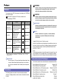
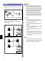
WARNING
Indicates a warning concerning operations that may lead to death or
injury to persons if not performed correctly. In order to use the
Manuals
printer safely, always pay attention to these warnings.
The electronic version (PDF) of the manuals is included on the CD-ROM that
comes with this printer.
CD-ROM
: Guides with this symbol are PDF manuals included on the
accompanying CD-ROM.
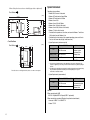
Instruction Manual
Name
Contents
Getting Started
Guide (this manual)
Describes the procedure for
installing this printer and the
preparations needed before
you can print with this
printer.
User's Guide
Describes the printing
procedures, routine
maintenance, and
troubleshooting.
Network Guide
Describes the procedures
for printing in a network
environment and managing
the printer.
Remote UI Guide
Describes the procedures
for operating the printer and
specifying the printer
settings from the web
browser.
*
Format
CD-ROM
File Name of the
PDF Manual
Manual_1.pdf*
CAUTION
Indicates a caution concerning operations that may lead to injury to
persons, or damage to property if not performed correctly. In order to
use the printer safely, always pay attention to these cautions.
IMPORTANT
Indicates operational requirements and restrictions. Be sure to read
these items carefully in order to operate the printer correctly, and to
avoid damage to the printer.
NOTE
Indicates a clarification of an operation, or contains additional
explanations for a procedure. Reading these notes is highly
recommended.
CD-ROM
Manual_2.pdf*
CD-ROM
Manual_3.pdf*
Copyright 2009 by Canon Inc. All rights reserved.
Manual_4.pdf*
No part of this publication may be reproduced or transmitted in any form or by
any means, electronic or mechanical, including photocopying and recording,
or by any information storage or retrieval system without the prior written
permission of Canon Inc.
CD-ROM
The PDF manuals are available from "CD-ROM Setup". (See "CD-ROM
Setup," on p. 54)
IMPORTANT
Notice
Canon makes no guarantees of any kind with regard to this manual. Canon shall
not be held liable for errors contained herein or for consequential or incidental
damages incurred as a result of acting on information contained in the manual.
Abbreviations Used in This Manual
To view the manual in PDF format, Adobe Reader/Adobe Acrobat Reader
is required. If Adobe Reader/Adobe Acrobat Reader is not installed on
In this manual, product names and model names are abbreviated as follows:
your system, please download it from the Adobe Systems Incorporated
Microsoft Windows 2000 operating system:
website.
Microsoft Windows XP operating system:
Microsoft Windows Server 2003 operating system:
Conventions
The following symbols are used in this manual to explain procedures,
restrictions, handling precautions, and instructions that should be observed
for safety.
2
Microsoft Windows Vista operating system:
Microsoft Windows Server 2008 operating system:
Microsoft Windows 7 operating system:
Windows 2000
Windows XP
Windows Server 2003
Windows Vista
Windows Server 2008
Windows 7
Microsoft Windows operating system:
Windows
LASER SHOT LBP3500:
LBP3500
Trademarks
Canon, the Canon Logo, LASER SHOT, LBP, and NetSpot are trademarks of
Canon Inc.
Adobe, Adobe Acrobat, and Adobe Reader are trademarks of Adobe
Systems Incorporated.
• When loading paper in portrait orientation: Width 210.0 to 297.0 mm; Length
210.0 to 431.8 mm*
* If the width of the paper in the 250-sheet universal cassette UC-67D is 279.5 to 297.0 mm,
the paper length should be 210.0 to 420.0 mm.
• When loading paper in landscape orientation: Width 210.0 to 297.0 mm;
Length 148.0 to 297.0 mm
IBM and AT are trademarks of International Business Machines Corporation.
Microsoft, Windows, and Windows Vista are trademarks or registered
trademarks of Microsoft Corporation in the U.S. and/or other countries.
Other product and company names herein may be the trademarks of their
respective owners.
Optional Accessories
The following optional accessories are available in order to use this printer to
its full extent. Purchase them to fulfill your needs. For the optional
accessories, contact your local authorized Canon dealer.
250-sheet Universal Cassette UC-67D
500-sheet Universal Cassette UC-67KD
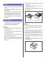
■ Paper Feeder
This printer is supplied with 2 paper sources: the paper cassette and multi-
■ Paper Cassette
purpose tray. By installing the optional paper feeder, up to 3 paper sources
A paper cassette is to be replaced with the one equipped with the printer unit
can be used.
or the optional paper feeder.
The paper feeder unit PF-67D consists of a paper feeder and paper cassette.
The 250-sheet universal cassette UC-67D is to be replaced with the paper
The paper cassette can be loaded with up to approximately 500 sheets of
cassette equipped with the printer unit.
plain paper (64 g/m2) at sizes of A3, B4, A4, B5, A5, Ledger (11 x 17), Legal,
The 500-sheet universal cassette UC-67KD is to be replaced with the paper
Letter, Executive, 16K and plain paper of the following custom paper sizes.
cassette equipped with the optional paper feeder.
• When loading paper in portrait orientation: Width 210.0 to 297.0 mm; Length
The paper cassette can be loaded with paper at sizes of A3, B4, A4, B5, A5,
Ledger (11 x 17), Legal, Letter, Executive, 16K and paper of the following
custom paper sizes.
210.0 to 431.8 mm
• When loading paper in landscape orientation: Width 210.0 to 297.0 mm;
Length 148.0 to 297.0 mm
Paper Feeder Unit PF-67D
3
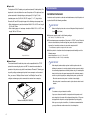
■ Duplex Unit
The duplex unit DU-67 enables you to perform automatic 2-sided printing. The
duplex unit is to be installed on the rear of the printer unit. The duplex unit can
perform automatic 2-sided printing on plain paper (60 - 90 g/m2) of the
standard paper sizes (A3, B4, A4, B5, A5, Ledger (11 x 17), Legal, Letter,
Executive, 8K, and 16K) and plain paper of the following custom paper sizes.
• When loading paper in portrait orientation: Width 210.0 to 297.0 mm; Length
210.0 to 431.8 mm
• When loading paper in landscape orientation: Width 210.0 to 297.0 mm;
Length 148.0 to 297.0 mm
Environments
Installation Environment
In order to use this printer in a safe and comfortable manner, install the printer in
a place that fulfills the following conditions.
IMPORTANT
Before installing the printer, be sure to read "Important Safety Instructions"
(See
CD-ROM
User's Guide).
● Use power supplies rated for the following voltages.
220 - 240 V (± 10 %) 50/60 Hz (± 2 Hz)
● The maximum power consumption of this printer is 1547 W* or less. Electrical
noise or a dramatic drop in mains voltage may cause the printer to operate
incorrectly or lose data, and can also cause the computer to fail.
* The instantaneous peak on startup shall not be counted.
● Use the printer in a location where the temperature and humidity are in the
following ranges.
Duplex Unit DU-67
Ambient temperature: 10 to 32.5°C (50 to 90.5°F)
Ambient humidity: 20 to 80 % RH (no condensation)
■ Network Board
The network board fits inside the printer and is compatible with the TCP/IP
protocol for connecting the printer to LAN. The network board enables the
operation of the printer using a built-in web browser "Remote UI" allowing you
IMPORTANT
Water droplets (condensation) may form inside the printer under the
following circumstances. Leave the printer for two hours or more to adjust
the surrounding temperature and humidity before using it. If water droplets
to specify settings and manage the printer from a computer on the network.
form inside the printer, the paper transport path will not function properly,
Also, you can use "NetSpot Device Installer" and "NetSpot Console" that
and this may result in paper jams, damage to the printer, or printer error.
configure and manage a printer connected to a network on a computer.
- When the room where the printer is installed is heated rapidly
- When the printer is moved from a cool or dry location to a hot or humid
location
NOTE
To customers using an ultrasonic humidifier
ERR
LNK
100
If you use an ultrasonic humidifier in conjunction with tap water or well
water, impurities in the water will be dispersed through the air. These can
Network board (NB-C1/NB-C2)
be trapped inside the printer, causing degradations in printing quality.
When you are using these humidifiers, it is therefore recommended that
you use purified water or other water that is free of impurities.
4
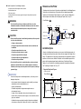
● Install the printer in the following locations.
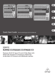
Dimensions of the Printer
- A location where sufficient space can be secured
- A well-ventilated room
- A flat, even surface
- A sturdy platform that can easily support the weight of the printer and optional
accessories
WARNING
The dimensions of each part of the printer are indicated in the following figures:
For details on the dimensions of the printer with the optional paper feeder
installed, see "Installing the Paper Feeder," on p. 39, and for the dimensions
with the duplex unit installed, see "Installing the Duplex Unit," on p. 47.
Front Surface
Do not install the printer near alcohol, paint thinner, or other
flammable substances. If flammable substances come into contact
93.8
with electrical parts inside the printer, it may result in a fire or
172.2
121.6
184
(mm)
40.6
88.6
Auxiliary Tray
electrical shock.
in a fire or electrical shock.
32.6
- A damp or dusty location
- A location exposed to smoke and steam such as cookeries and
humidifiers
438.7
277
344
Auxiliary Tray
Multi-purpose Tray
518
CAUTION
• Do not install the printer in the following locations, as this may result
286.6
272
Tray Extension
Tray Extension
Auxiliary Tray
Sub-output Tray
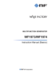
Installation Space
- A location exposed to rain or snow
- A location near water faucets or water
- A location exposed to direct sunlight
- A location subject to high temperatures
- A location near open flames
• Do not install the printer in unstable locations, such as unsteady
platforms or inclined floors, or in locations subject to excessive
Select an installation location where you can secure the following amounts of
free space around the printer, and a surface that can support the weight of the
printer. The dimensions of the space required around the components and the
positions of the feet are as follows. For details on the installation space of the
printer with the optional paper feeder installed, see "Installing the Paper
Feeder," on p. 39, and for the installation space with the duplex unit installed,
see "Installing the Duplex Unit," on p. 47.
vibrations, as this may cause the printer to fall or tip over, resulting in
personal injury.
• Required Peripheral Space
• Printer unit only
Front Surface
IMPORTANT
Do not install the printer in the following locations, as this may result in
1193.7
430
- In rooms such as laboratories where chemical reactions occur
- A place where salt content, corrosive gases such as ammonia, or toxic
gases are contained
544
100
- A location near products that generate magnetic waves or
electromagnetic waves
718
- A poorly ventilated room
200
- An environment where the temperature and/or humidity can change
dramatically, or where condensation occurs
(mm)
100
damage to the printer.
325
- A platform that may warp from the weight of the printer and optional
accessories, or the printer is liable to sink (such as a carpet or mat)
5
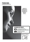
System Environment
• When all the optional accessories are installed (paper feeder + duplex unit)
Operating system software
Front Surface
(mm)
100
718
673.1
200
465
100
1228.7
325
• Foot Positions
(mm)
105.9
312.1
20.7
Windows 2000/XP/Server 2003
44.4
34.6
Front Surface
• Windows 2000 Server or Professional
• Windows XP Professional or Home Edition
• Windows XP Professional x64 Edition
• Windows Server 2003
• Windows Server 2003 x64 Editions
• Windows Vista (32-bit or 64-bit version)
• Windows Server 2008 (32-bit or 64-bit version)
• Windows 7 (32-bit or 64-bit version)
✝ For details on the procedures, instructions, and so on for Windows 7 and Server
2008, refer to those for Windows Vista.
✝ For details on the latest status of the supported operating systems and Service
Pack, see the Canon website (http://www.canon.com/).
• System Requirements (minimum required)
364.4
395
Windows Vista
Memory (RAM) *1
128 MB or more
Conforms to the
minimum system
requirements for
Windows Vista
Hard Disk *2
120 MB or more
120 MB or more
CPU
Pentium II
300 MHz or more
88.4
109.2
(PC/AT Compatibles)
104.4
313.6
20.7
The rubber feet are 1 mm high and their top surface is 12 mm x 12 mm square.
*1 As the amount of available memory varies depending on the system configuration of the
computer or application you are using, the above environment does not guarantee printing in
all cases.
*2 This indicates free hard disk space required for installing the printer driver and manuals using
Easy Installation. Required free hard disk space varies depending on the system
environment or installation method.
• System Requirements (recommended)
Windows 2000/XP/Server 2003
CPU
Pentium III
600 MHz or more
Memory (RAM)
256 MB or more
Windows Vista
Conforms to the
recommended system
requirements for
Windows Vista
Interface
When connecting with USB
USB 2.0 Hi-Speed/USB Full-Speed (USB1.1 equivalent)
When connecting to a network (Requires the optional network board.)
• Connector: 10BASE-T or 100BASE-TX
• Protocol: TCP/IP
6
NOTE
• When using Sound, a PC synthesizer (and the driver for PCM synthesizer)
must be installed in your computer. Do not use a PC Speaker driver
(speaker.drv etc.).
• This printer uses bi-directional communication. Operation of the printer
when connected via unidirectional communication equipment has not
been tested, and as a result, Canon cannot guarantee printer operation
when the printer is connected using unidirectional print servers, USB hubs
or switching devices.
7
NOTE
Step
1
Step1
Installing the Printer
and Removing the
Packing Materials on the
Outside of the Printer
• The life of the supplied toner cartridge is approximately 6,000 pages on
the basis of "ISO/IEC 19752"* when printing A4 size paper with the default
print density setting.
* "ISO/IEC 19752" is the global standard related to "Method for the determination of
toner cartridge yield for monochromatic electrophotographic printers and multifunction devices that may contain printer components" issued by ISO (International
Organization for Standardization).
• The toner cartridge supplied with the printer is different from the
replacement toner cartridge. For purchasing the replacement toner
cartridge, see "Chapter 5 Routine Maintenance" in
CD-ROM
User's Guide.
• When you connect this printer to your computer with a USB cable, use the
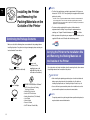
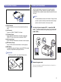
Confirming the Package Contents
supplied USB cable or a USB cable with the following symbol.
Make sure that all the following items are contained in the package before
installing the printer. If any item is missing or damaged, please contact your
local authorized Canon dealer.
Carrying the Printer to the Installation Site
and Removing the Packing Materials on
the Outside of the Printer
Printer
(The paper cassette is attached.)
Power cord
(The form of the
supplied power cord
may differ from the one
in the above illustration.)
Carry the printer unit to the installation site after securing the site, then remove
the packing materials on the outside of the printer.
IMPORTANT
• When installing the optional paper feeder, place it on the installation site
before carrying the printer unit to the installation site. For details on
Toner cartridge
USB cable
8
CD-ROM "LBP3500 User Software"
• CAPT (Canon Advanced Printing
Technology) Software
• NetSpot Device Installer
• Canon CAPT Print Monitor
• Getting Started Guide (This Manual)
• User's Guide
• Network Guide
• Remote UI Guide
• CAPT Windows Firewall Utility
installing the paper feeder, see "Installing the Paper Feeder," on p. 39.
• Secure sufficient space around the printer at the installation site so that
you can install the optional accessories and connect cables.
NOTE
The packing materials may be changed in form or position to be placed, or
may be added or removed without notice.
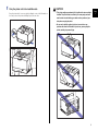
1
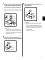
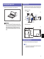
Carry the printer unit to the installation site.
Carry the printer with 2 or more people by holding the center of the lift handles on
the lower portion of the printer and lifting it up at the same time.
CAUTION
• This printer weighs approximately 19.4 kg without the toner cartridge
installed. The printer must be carried by 2 or more people, and care
must be taken to avoid hurting your back or other portions of your
body when carrying the printer.
• Be sure not to hold the printer by the front or rear side or any
portions other than the lift handles. If you do so, you may drop the
printer, resulting in personal injury.
9
Step
1
• The back portion (A) of the printer is relatively heavy. Be careful not
to get off-balanced when lifting the printer. If you do so, you may
Step
1
drop the printer, resulting in personal injury.
(A)
IMPORTANT
Carry the printer with the tape that secures the front cover, etc. attached.
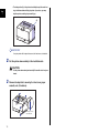
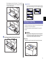
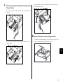
2
Put the printer down carefully at the installation site.
CAUTION
Put the printer down slowly and carefully. Be careful not to hurt your
hands.
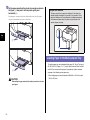
3
Remove the tape that is securing the front cover, paper
cassette, etc. (5 locations).
This tape is to be
removed later.
10
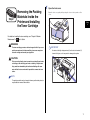
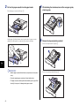
1
Step2
Removing the Packing
Materials Inside the
Printer and Installing
the Toner Cartridge
Open the front cover.
Open the front cover gently while pressing the lever on the top surface of the
cover.
Step
2
For details on handling the toner cartridge, see "Chapter 5 Routine
Maintenance" in
User's Guide.
CD-ROM
WARNING
The toner cartridge generates a low level magnetic field. If you use a
IMPORTANT
cardiac pacemaker and feel abnormalities, please move away from
Do not touch the high-voltage contact (A) or the electrical contact (B)
the toner cartridge and consult your physician.
shown in the figure, as this may result in damage to the printer.
CAUTION
(B)
Take care not to allow the toner to come into contact with your hands
or clothing, as this will dirty your hands or clothing. If they become
dirty, wash them immediately with cold water. Washing with warm
water will set the toner and make it impossible to remove the toner
stains.
(A)
NOTE
The packing materials may be changed in form or position to be placed, or
may be added or removed without notice.
11
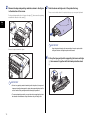
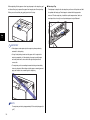
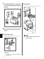
2
Remove the tape and packing materials shown in the figure
in the direction of the arrow.
3
Take the toner cartridge out of the protective bag.
There are cuts on both sides of the protective bag, so you can open it by hand.
For the packing material on the left, remove the tape a, then remove the packing
material in the direction of the arrow b.
Step
2
a
b
IMPORTANT
Keep the protective bag for the toner cartridge. It may be required after
Remove the tape shown in the figure.
taking out the toner cartridge for printer maintenance.
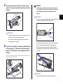
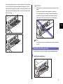
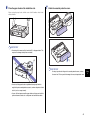
4
Pull up the tape gently while supporting the toner cartridge
a, then remove it together with the black protective sheet
b.
a
IMPORTANT
• If there is any packing material remaining inside the printer, this may result
in poor print quality or damage to the printer when operating the printer. Be
sure to remove all the packing materials following the procedure.
• The removed packing materials are required when transporting the printer
for relocation or maintenance. Keep them where they will not get lost.
12
b
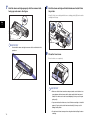
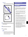
5
Hold the toner cartridge as shown in the figure, shake it
gently 5 or 6 times to evenly distribute the toner inside the
cartridge.
CAUTION
If the sealing tape is pulled out forcefully or stopped at midpoint,
toner may spill out. If the toner gets into your eyes or mouth, wash
them immediately with cold water and immediately consult a
physician.
Step
2
IMPORTANT
• Do not pull the sealing tape diagonally, upwards, or downwards. If the tape
is severed, it may become difficult to pull out completely.
IMPORTANT
• If toner is not distributed evenly, this may result in deterioration in print
quality. Be sure to carry out this procedure properly.
• Be sure to shake the toner cartridge gently. If you do not shake the
cartridge gently, toner may spill out.
• Pull out the sealing tape completely from the toner cartridge. If any tape
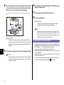
6
remains in the toner cartridge, this may result in poor print quality.
Place the toner cartridge on a flat surface, fold back the tab
of the sealing tape a, and then pull out the sealing tape
(approx. 72 cm long) gently b while supporting the toner
cartridge.
• When pulling out the sealing tape, be careful not to touch the toner
cartridge memory (A) or not to hold the drum protective shutter (B) with
your hands.
Remove the sealing tape by hooking your fingers into the tab and pulling it out
straight in the direction of the arrow.
(A)
a
(B)
IMPORTANT
b
Dispose of the packing materials according to local regulations.
13
7
Hold the toner cartridge properly with the arrowed side
facing up as shown in the figure.
8
Hold the toner cartridge with both hands and install it into
the printer.
Align (A) of the toner cartridge with the toner cartridge guides (B), then insert the
cartridge until it stops.
(A)
Step
2
(B)
(B)
(A)
IMPORTANT
Do not hold the toner cartridge in a manner that is not directed in this
procedure.
9
Close the front cover.
Close the front cover completely.
IMPORTANT
• Make sure that the front cover does not open (make sure that there is no
space between the front cover and the printer and that the front cover is
stable). If the front cover is not closed completely, this may result in poor
print quality.
• If you cannot close the front cover, check if the toner cartridge is installed
properly. If you try to close the front cover forcefully, this may result in
damage to the printer.
• Do not leave the front cover open for a long time after installing the toner
14
cartridge.
Step3
Removing the Packing
Materials in the Paper
Cassette and Loading
Paper
Loading Paper in the Paper Cassette
The paper cassette (Cassette 1) can be loaded with up to approximately 250
sheets of plain paper (60 - 90 g/m2) at sizes of A3, B4, A4, B5, A5, Ledger
(11 x 17), Legal, Letter, Executive, and 16K.
You can also load paper of the following custom paper sizes. When loading
paper at sizes of A3, B4, etc. in portrait orientation, adjust the length of the
paper cassette.
- When loading paper in portrait orientation: Width 210.0 to 297.0 mm;
Length 210.0 to 431.8 mm*
For details on handling the multi-purpose tray or paper cassette, see
"Chapter 2 Loading and Outputting Paper" in
User's Guide.
By default, this printer feeds paper from two paper sources: the paper
cassette (Cassette 1) and multi-purpose tray. Also, paper can be fed from
up to 3 paper sources by installing the optional paper feeder (Cassette 2).
This section only describes the procedure for loading plain paper of
standard size in the paper cassette and multi-purpose tray. When loading
paper other than plain paper, or when installing the optional paper feeder
on the printer, see the following directions.
*
If the paper width is 279.5 to 297.0 mm, the paper length should be 210.0 to
420.0 mm.
CD-ROM
- When loading paper in landscape orientation: Width 210.0 to 297.0 mm;
Length 148.0 to 297.0 mm
Portrait orientation
Landscape orientation
Ex. A3
● When loading heavy paper, transparencies, labels, envelopes, Index Card
size media, or custom size paper
See "Chapter 2 Loading and Outputting Paper" in
User's Guide
Ex. A4
CD-ROM
● When installing the optional paper feeder in the printer
See Installing the Paper Feeder: p. 39
● When loading paper in the paper cassette of the paper feeder
See "Chapter 2 Loading and Outputting Paper" in
User's Guide
CD-ROM
Paper that can be loaded in
portrait orientation:
A3, B4, Ledger (11 x 17), Legal
Paper that can be loaded in
landscape orientation:
A4, B5, A5, Letter, Executive, 16K
NOTE
For more details on the usable paper, see "Chapter 2 Loading and
Outputting Paper" in
CD-ROM
User's Guide.
IMPORTANT
Do not pull out the paper cassette while the printer is printing. This may
result in paper jams or damage to the printer.
NOTE
The packing materials may be changed in form or position to be placed, or
may be added or removed without notice.
15
Step
3
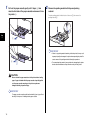
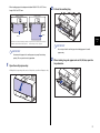
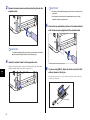
1
Pull out the paper cassette gently until it stops a, then
raise the front side of the paper cassette and remove it from
the printer b.
2
Remove the packing material with tape and packing
material.
Turn the packing material in the direction of the arrow a, then remove the
packing material b.
b
a
Step
3
a
IMPORTANT
• If there is any packing material remaining inside the printer, this may result
in poor print quality or damage to the printer when operating the printer. Be
sure to remove all the packing materials following the procedure.
b
• The removed packing materials are required when transporting the printer
for relocation or maintenance. Keep them where they will not get lost.
CAUTION
Be sure to take the paper cassette out of the printer before loading
paper. If paper is loaded while the paper cassette is partially pulled
out, the paper cassette may drop or the printer may become
damaged resulting in personal injury.
IMPORTANT
The paper cassette cannot be pulled out horizontally. If you try to pull it out
forcefully, this may result in damage to the paper cassette.
16
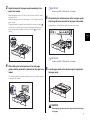
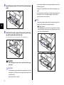
3
IMPORTANT
Adjust the length of the paper cassette according to the
paper to be loaded.
When loading paper at sizes of A4, B5, A5, Letter, Executive, and 16K, shorten
the paper cassette.
When loading paper at sizes of A3, B4, Ledger (11 x 17), and Legal, extend the
paper cassette.
To adjust the length of the paper cassette, align the lock release lever with "
"
to release the lock, slide the paper cassette by holding the rear portion of the
paper cassette, and then align the lock release lever with "
" to lock the
cassette.
Do not use the "A4R", "LTRR", and "8.5 x 13" position.
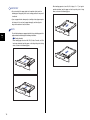
5
While holding the lock release lever of the rear paper guide,
slide the guide to the size mark for the paper to be loaded.
Align the position of (A) with the size mark for the paper to be loaded.
Step
3
(A)
IMPORTANT
Do not use the "A4R", "LTRR", and "8.5 x 13" position.
4
While holding the lock release lever of the side paper
guides, slide the guides to the size mark for the paper to be
loaded.
6
Load the paper stack so that the rear edge is aligned with
the paper guide.
The side paper guides move together. Align the position of (A) with the size mark
for the paper to be loaded.
(A)
CAUTION
When loading paper, take care not to cut your hands with the edges
of the paper.
17
IMPORTANT
• Be sure to check if the paper guide is at the position of the size of the
loaded paper. If the paper guide is set at a wrong position, this may result
in misfeeds.
• If you use paper that has been poorly cut, multiple sheets of paper may be
fed at once. In this case, fan the paper thoroughly, and then align the
edges of the stack on a hard, flat surface.
NOTE
To print letterhead paper or paper printed with a logo, load the paper in the
Step
3
proper orientation according to the following instructions:
(
: Feeding direction)
- When loading paper at a size of A4, B5, A5, Letter, Executive, or 16K in
landscape orientation, load the paper so that the printing side is facing
down, as shown in the following figures.
18
- When loading paper at a size of A3, B4, Ledger (11 x 17), or Legal in
portrait orientation, load the paper so that the printing side is facing
down, as shown in the following figures.
7
Hold down the paper as shown in the figure, make sure that
the paper stack does not exceed the load limit marks (A),
and then set it under the hooks (B) on the paper guides.
9
Adjust the paper size register dial (A) to set the dial to the
size of the loaded paper.
Make sure that there is sufficient space between the hooks of the paper guides
and the paper stack. If there is no sufficient space, slightly reduce the amount of
paper.
(B)
(A)
(B)
(A)
(A)
Step
3
(B)
IMPORTANT
• Make sure that the paper size the paper size register dial is indicating
corresponds with the size of the loaded paper before setting the paper
cassette in the printer. If the paper size that the paper size register dial is
indicating does not correspond with the size of the loaded paper, this may
IMPORTANT
The paper capacity of the paper cassette is approximately 250 sheets of
plain paper (64 g/m2). Be sure that the paper stack does not exceed the
result in printer malfunction.
• Do not use "A4R", "LTRR", and "8.5 x 13".
load limit marks on the paper guides. If the paper stack exceeds the load
limit marks, this may result in misfeeds.
8
Holding the tab of the paper size setting switch, set the
paper size setting switch (A) to the size of the loaded paper.
(A)
A3, B4, A4, B5, A5, 16K
Ledger (11 x 17), Legal,
Letter, Executive,
Custom Paper Size
19
10 Set the paper cassette in the printer at an angle as shown in
the figure a, then push it into the printer gently and
horizontally b.
Push the paper cassette into the printer firmly until the front side of the paper
cassette is flush with the front surface of the printer.
● Paper Level Indicator
The paper cassette has a paper level indicator (A) that shows the
amount of paper remaining in the cassette. If the cassette is full, the
paper level indicator is at the top. Because the indicator moves down
as the amount of paper drops, this gives a rough estimate of the
amount of paper remaining.
Step
3
a
(A)
Loading Paper in the Multi-purpose Tray
The multi-purpose tray can be loaded with plain paper (60 - 90 g/m2) at sizes of
A3, B4, A4, B5, A5, Ledger (11 x 17), Legal, Letter, Executive, Index Card, 8K,
b
and 16K. You can also load heavy paper, transparencies, labels, envelopes,
and paper of the following custom paper sizes.
- When loading paper in portrait orientation: Width 98.0 to 312.0 mm; Length
CAUTION
When setting the paper cassette in the printer, be careful not to catch
your fingers.
20
148.0 to 470.0 mm
- When loading paper in landscape orientation: Width 210.0 to 297.0 mm;
Length 148.0 to 297.0 mm
Landscape orientation
2
Pull out the auxiliary tray.
Portrait orientation
Ex. A4
Ex. A3
Step
3
Paper that can be loaded in landscape orientation: Paper that can be loaded in portrait orientation:
A4, B5, A5, Letter, Executive, Index Card, 16K
A3, B4, Ledger (11 x 17), Legal, 8K
IMPORTANT
Be sure to pull out the auxiliary tray when loading paper in the multi-
IMPORTANT
purpose tray.
Do not touch the paper in the multi-purpose tray or pull it out during
printing. This may result in a faulty operation.
1
Open the multi-purpose tray.
3
When loading long-size paper such as A3, B4, etc, open the
tray extension.
Holding the blue opening at the center of the printer, open the multi-purpose tray.
21
4
Spread the paper guides a little wider than the actual paper
width.
• If the rear edge of the paper stack is not properly aligned, this may result in
misfeeds or paper jams.
• If the paper is curled or folded at corners, flatten it before loading it in the
printer.
• If you use paper that has been poorly cut, multiple sheets of paper may be
fed at once. In this case, fan the paper thoroughly, and then align the
edges of the stack on a hard, flat surface.
NOTE
To print letterhead paper or paper printed with a logo, load the paper in the
proper orientation according to the following instructions:
Step
3
(
5
Gently load the stack of paper with the printing side facing
up until it touches the back of the tray.
Be sure that the paper stack is loaded under the load limit guides (A).
(A)
CAUTION
When loading paper, take care not to cut your hands with the edges
of the paper.
IMPORTANT
• The multi-purpose tray can be loaded with up to approximately 100 sheets
of plain paper (64 g/m2). Make sure that the paper stack does not exceed
the load limit guides.
• Load the paper so that it is straight.
22
: Feeding direction)
- When loading paper at a size of A4, B5, A5, Letter, Executive, or 16K in
landscape orientation, load the paper so that the printing side is facing
up, as shown in the following figures.
- When loading paper at a size of A3, B4, Ledger (11 x 17), Legal, or 8K in
portrait orientation, load the paper so that the printing side is facing up,
as shown in the following figures.
IMPORTANT
Be sure to align the paper guides with the width of the paper. If the paper
guides are too loose or too tight, this may result in misfeeds or paper jams.
Step
3
Selecting an Output Tray
This printer has two output trays: "output tray" on the top of the printer unit and
"sub-output tray" on the rear of the printer unit.
Do not switch one output tray to another during printing. This may result in
paper jams.
CAUTION
Keep your hands or clothing away from the roller in the output area.
Even if the printer is not printing, sudden rotation of the roller may
6
Align the paper guides with both sides of the stack.
catch your hands or clothing, resulting in personal injury.
■ Output Tray
Printed paper is output to the output tray with the printed side facing down.
23
When outputting A3 size paper or other long-size paper to the output tray, pull
■ Sub-output Tray
out the auxiliary tray to prevent the paper from hanging out of the output tray.
Printed paper is output to the sub-output tray on the rear of the printer unit with
When you use the auxiliary tray, gently open it until it stops.
the printed side facing up. Printed paper is stacked with the page order
reversed. The sub-output tray is suitable to print transparencies, labels, or
envelopes that curl easily, since the printed paper is output flattened.
Step
3
IMPORTANT
• Printed paper can be output only to the output tray when performing
automatic 2-sided printing.
• During 2-sided printing, do not touch the paper until it is output to the
output tray completely. In 2-sided printing, the paper is partially output
once after printed on its surface and is fed again to be printed on its
reverse side.
• The output tray and its surroundings become hot during or immediately
after using the printer. When taking out of the paper or removing jammed
paper, do not touch the surroundings of the output tray.
NOTE
The output tray can hold up to approximately 250 sheets of plain paper (64
g/m2).
24
When outputting A4 size paper or other large-size paper to the sub-output tray,
IMPORTANT
pull out the auxiliary tray to prevent the paper from hanging out of the sub-
• Be sure to close the sub-output tray before performing automatic 2-sided
output tray. When outputting A3 size paper or other long-size paper to the sub-
printing.
output tray, open the tray extension. When you use the tray extension, gently
• Do not open the sub-output tray during automatic 2-sided printing.
open it until it stops.
• The sub-output tray and its surroundings become hot during printing or
immediately after printing. When taking out of the paper or removing
jammed paper, do not touch the surroundings of the sub-output tray.
Step
3
NOTE
The sub-output tray can hold up to approximately 50 sheets of plain paper
(64 g/m2).
Switching to the Sub-output Tray
Switch an output tray to the sub-output tray using the following procedure.
1
Open the sub-output tray a.
a
25
When outputting A4 size paper or other large-size paper, pull out the auxiliary tray
b.
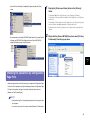
2
Select [Auto] or [Sub-output Tray] in [Paper Output] in the
[Finishing] sheet in the printer driver.
Make sure that the sub-output tray is opened before selecting [Auto]. If the suboutput tray is closed, printed paper is output to the output tray.
b
Step
3
When outputting A3 size paper or other long-size paper, open the tray extension
c.
c
IMPORTANT
Paper is output to the sub-output tray with the printed side facing up.
Therefore, when printing from the first page, the paper is stacked with the
page order reversed. If you want the printer to output paper with the pages
collated in the right order, select the [Reverse Output Order When Using
Sub-output Tray] check box in the [Finishing Details] dialog box in the
[Finishing] sheet, and you can output paper with the pages collated in the
right order because the printer prints from the last page (The [Reverse
Output Order When Using Sub-output Tray] check box is selected at the
default setting).
NOTE
When installing the printer driver, see "Connecting the Printer to a
Computer and Installing the CAPT Software," on p. 29 in Step 5.
26
2
Switching to the Output Tray
Select [Auto] or [Output Tray] in [Paper Output] in the
[Finishing] sheet in the printer driver.
Switch an output tray to the output tray using the following procedure.
1
Make sure that the sub-output tray is closed before selecting [Auto]. If the suboutput tray is opened, printed paper is output to the sub-output tray.
Close the tray extension and auxiliary tray a, then close the
sub-output tray b.
Step
3
a
b
NOTE
When installing the printer driver, see "Connecting the Printer to a
Computer and Installing the CAPT Software," on p. 29 in Step 5.
27
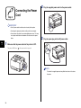
Step 4
2
Plug the supplied power cord into the power socket.
3
Plug the power plug into the AC power outlet.
Connecting the Power
Cord
IMPORTANT
• One AC power outlet should be used exclusively for the printer.
• Do not plug the power plug into the auxiliary outlet on a computer.
• Do not connect this printer to an uninterruptible power source. This may
cause printer malfunction or breakdown at the occurrence of a power
failure.
Step
4
1
Make sure that the power switch of the printer is OFF.
The printer is OFF when "
" of the power switch is pressed.
NOTE
The form of the supplied power cord may differ from the one in the above
illustration.
28
• When you connect this printer to your computer with a USB cable, use the
supplied USB cable or a USB cable with the following symbol.
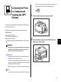
Step 5
Connecting the Printer
to a Computer and
Installing the CAPT
Software
1
Make sure that the printer and computer are OFF.
In this section, connect the printer to a computer with a USB cable, and
then install the printer driver.
For details on using this printer in a network environment, see the
following directions.
● Installing the Network Board
See Installing the Network Board: p. 49
● Installing the CAPT Software
See "Chapter 2 Setting Up the Network Environment for Printing" in Network
Guide
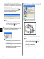
2
Connect the B-type (square) end of the USB cable to the
USB connector on the printer.
Step
5
WARNING
When plugging or unplugging the USB cable when the power plug is
plugged in an AC power outlet, do not touch the metal part of the
connector, as this may result in electrical shock.
IMPORTANT
• Do not plug or unplug the USB cable while the computer and printer are
ON, as this may result in damage to the printer.
• This printer uses bi-directional communications while printing. Connecting
to print servers, USB hubs or switching devices that require uni-directional
communication may result in printer error.
• When starting Windows, be sure to log on as a member of Administrators.
NOTE
• The screen shots used in this section are from Windows XP Professional.
29
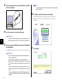
3
NOTE
Connect the A-type (flat) end of the USB cable to the USB
port on the computer.
If you are using Windows Vista and the [User Account Control] dialog box
appears, click [Allow].
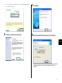
6
Click [Easy Installation] or [Custom Installation].
[Easy Installation] allows you to install the printer driver and the instruction
manuals simultaneously. If you do not install the manuals, select [Custom
Installation].
4
Turn the computer on and start up Windows.
IMPORTANT
If a Wizard or dialog box appears by the Plug and Play automatic setup,
click [Cancel], and then install the CAPT software using this procedure.
Step
5
5
Insert the supplied "LBP3500 User Software" CD-ROM into
the CD-ROM drive.
If the CD-ROM is already in the drive, eject the disk and re-insert it into the drive.
IMPORTANT
• If you are using Windows Vista and the [AutoPlay] dialog box appears,
click [Run AUTORUN.EXE].
• If CD-ROM Setup does not appear, display it using the following
procedures. (The CD-ROM drive name is indicated as "D:" in this manual.
The CD-ROM drive name may differ depending on the computer you are
using.)
- If you are using an operating system other than Windows Vista, select
[Run] from the [Start] menu, enter "D:\English\MInst.exe", and then click
[OK].
- If you are using Windows Vista, enter "D:\English\MInst.exe" in [Start
Search] under the [Start] menu, and then press the [ENTER] key on your
keyboard.
30
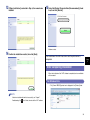
7
Click [Install].
8
If you selected [Custom Installation] in Step 6, clear the [Online Manuals] check
box, and then click [Install].
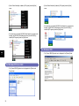
9
Confirm the contents, then click [Yes].
10 Select [Install with USB Connection], then click [Next].
Click [Next].
Step
5
Depending on the system environment, a message that prompts you to restart the
computer may appear. In this case, restart the computer and continue the
installation.
31
If you are using Windows XP Service Pack 2 or another operating system
equipped with Windows Firewall, the following screen is displayed. Specify whether
to configure Windows Firewall to unblock communication with the client computers
when sharing the printer on a network.
Click [Yes] when you share the printer on a network. After completing the
installation, see "Chapter 3 Setting Up the Printing Environment" in CD-ROM User's
Guide and specify the settings for sharing the printer on the network.
Click [No] when you do not share the printer on a network.
NOTE
12 When the following screen is displayed, turn the printer ON.
Press " " of the power switch to turn the printer ON.
Even after the installation, you can change the Firewall settings using
"CAPT Windows Firewall Utility" in the supplied CD-ROM. For more
details, see "Chapter 8 Appendix" in
CD-ROM
User's Guide.
11 The message <Installation cannot be stopped once it starts.
Step
5
Do you want to continue?> appears. Click [Yes].
Installation of the USB class driver and the printer driver starts automatically.
NOTE
• If you are using Windows 2000 and the [Digital Signature Not Found]
dialog box appears, click [Yes].
• If you are using Windows XP/Server 2003 and the [Hardware Installation]
dialog box appears, click [Continue Anyway].
• If you are using Windows Vista and the [Windows Security] dialog box
appears, click [Install this driver software anyway].
32
NOTE
• If the printer is not recognized automatically even after the USB cable is
connected, see "Chapter 7 Troubleshooting" in
CD-ROM
User's Guide.
• If you are using Windows XP/Server 2003 and the [Hardware Installation]
dialog box appears, click [Continue Anyway].
• If you are using Windows Vista and the [Windows Security] dialog box
appears, click [Install this driver software anyway].
13 If [Easy Installation] is selected in Step 6, the manuals are
installed.
15 Select the [Restart Computer Now (Recommended)] check
box, then click [Restart].
Windows restarts.
14 Confirm the installation results, then click [Next].
The installation of the USB class driver and the printer driver is
completed.
Step
5
After Completing Installation
When the installation of the CAPT software is completed, an icon and folder
will be created.
For Windows Vista
• The [Canon LBP3500] printer icon is displayed in the [Printers] folder.
NOTE
If the driver installation did not finish successfully, see "Chapter 7
Troubleshooting" in
CD-ROM
User's Guide, then reinstall the CAPT software.
33
• [Canon Printer Uninstaller] is added to [All Programs] under the [Start]
menu.
• [Canon Printer Uninstaller] is added to [All Programs] under the [Start]
menu.
• If the manuals are installed, [LBP3500 Online Manuals] is created on the
desktop, and [LBP3500 Online Manuals] under [Canon LBP3500] is
added to [All Programs] under the [Start] menu.
• If the manuals are installed, [LBP3500 Online Manuals] is created on the
desktop, and [LBP3500 Online Manuals] under [Canon LBP3500] is
added to [All Programs] under the [Start] menu.
For Windows 2000
Step
5
• The [Canon LBP3500] printer icon is displayed in the [Printers] folder.
For Windows XP/Server 2003
• The [Canon LBP3500] printer icon is displayed in the [Printers and
Faxes] folder.
34
• [Canon Printer Uninstaller] is added to [Programs] under the [Start]
menu.
1
Display the [Printers and Faxes] folder or the [Printers]
folder.
For Windows 2000: From the [Start] menu, select [Settings] ➞ [Printers].
For Windows XP Professional/Server 2003: From the [Start] menu, select [Printers
and Faxes].
For Windows XP Home Edition: From the [Start] menu, select [Control Panel], and
then click [Printers and Other Hardware] ➞ [Printers and Faxes].
For Windows Vista: From the [Start] menu, select [Control Panel], and then click
[Printer].
• If the manuals are installed, [LBP3500 Online Manuals] is created on the
desktop, and [LBP3500 Online Manuals] under [Canon LBP3500] is
added to [Programs] under the [Start] menu.
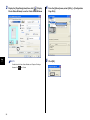
2
Right-click the [Canon LBP3500] icon, then select [Printing
Preferences] from the pop-up menu.
Step
5
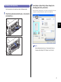
Checking the Operations by Configuration
Page Print
Before using the printer for the first time, be sure to perform Configuration Page
Print to check the operations using the following procedure. Configuration Page
Print prints the optional settings of the printer and printer status such as
[Number of Total Printed Pages].
NOTE
• Configuration Page Print is designed to be printed on A4 size paper. Load
A4 size paper.
• The screen shots used in this section are from Windows XP Professional.
35
3
Step
5
Display the [Page Setup] sheet, then click [
] (Display
Printer Status Window) to run the Printer Status Window.
5
NOTE
For details on the Printer Status Window, see "Chapter 4 Printing a
Document" in
36
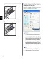
4
CD-ROM
User's Guide.
From the [Options] menu, select [Utility] ➞ [Configuration
Page Print].
Click [OK].
Configuration Page Print is printed.
Displaying the Manuals
This section describes the procedures for displaying the following manuals in
PDF format.
Instruction Manual Name
Contents
Getting Started Guide
(this manual)
Describes the procedure for installing this printer and
the preparations needed before you can print with
this printer.
User's Guide
Describes the printing procedures, routine
maintenance, and troubleshooting.
Network Guide
Describes the procedures for printing in a network
environment and managing the printer.
Remote UI Guide
Describes the procedures for operating the printer
and specifying the printer settings from the web
browser.
IMPORTANT
To display the manuals in PDF format, Adobe Reader/Adobe Acrobat
Reader is required. If Adobe Reader/Adobe Acrobat Reader is not
Step
5
installed on your system, please download it from the Adobe Systems
Incorporated website.
When Displaying a Manual Installed on a Computer
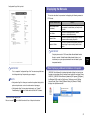
IMPORTANT
This is a sample of Configuration Page Print. The contents may differ from
the Configuration Page Print printed by your computer.
NOTE
• Configuration Page Print allows you to confirm the optional settings of the
printer and printer status such as the total number of print pages.
[LBP3500 Online Manuals] is displayed by double-clicking the shortcut icon
created on the desktop when the manuals were installed or selecting [Canon
LBP3500] - [LBP3500 Online Manuals] added to [All Programs] ([Programs]
for Windows 2000) under the [Start] menu. Clicking any one of [Getting
Started Guide], [User's Guide], [Network Guide], or [Remote UI Guide]
displays the respective manuals.
• If Configuration Page Print was not printed properly, see "Chapter 7
Troubleshooting" in
CD-ROM
User's Guide and reinstall the CAPT software.
The printer is now ready to print.
Be sure to read "
User's Guide" to make full use of the printer functions.
CD-ROM
37
Displaying the Manuals from CD-ROM Setup
Display the manuals from the CD-ROM supplied with the printer.
1
Insert the supplied "LBP3500 User Software" CD-ROM into
the CD-ROM drive.
NOTE
• If you are using Windows Vista and the [AutoPlay] dialog box appears,
click [Run AUTORUN.EXE].
• If CD-ROM Setup does not appear, display it using the following
procedures. (The CD-ROM drive name is indicated as "D:" in this manual.
The CD-ROM drive name may differ depending on the computer you are
using.)
- If you are using an operating system other than Windows Vista, select
[Run] from the [Start] menu, enter "D:\English\MInst.exe", and then click
[OK].
- If you are using Windows Vista, enter "D:\English\MInst.exe" in [Start
Search] under the [Start] menu, and then press the [ENTER] key on your
keyboard.
Step
5
• If you are using Windows Vista and the [User Account Control] dialog box
appears, click [Allow].
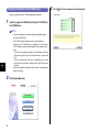
2
38
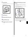
Click [Display Manuals].
3
Click [
] next to the name of the desired guide.
IMPORTANT
Step6
Installing the Optional
Accessories
Do not touch the connector (A) or feed roller (B) in the paper feeder. This
may result in damage to the printer or misfeeds.
(A)
(B)
Installing the Paper Feeder
The paper feeder is to be installed at the bottom of the printer unit.
Make sure that all the following items are contained in the package before
installing the paper feeder. If any item is missing or damaged, please contact
your local authorized Canon dealer.
Paper Feeder PF-67D
Cassette Protective Cover
Screws (4 pieces)*
* They are not to be used.
WARNING
Step
6
Be sure to turn the printer OFF, unplug the power plug, and then
disconnect all the interface cables and power cord from the printer
before installing the paper feeder. Otherwise, the power cord or
interface cables may be damaged, resulting in a fire or electrical
shock.
39
Installation Space
Moving the Printer
The dimensions of each part, foot positions, and the space required for using
the printer with the paper feeder installed are indicated in the following
figures:
When installing the paper feeder in the printer after installing the printer,
move the printer to an appropriate location temporarily using the following
procedure.
• Dimensions of the Printer
WARNING
Front Surface
93.8
Be sure to turn the printer and computer OFF, unplug the power plug,
184
172.2
121.6
40.6
and then disconnect all the interface cables from the printer before
(mm)
Auxiliary Tray
moving the printer. Otherwise, the power cord or interface cables
88.6
406.1
473.1
518
Auxiliary Tray
415.7
401.1
may be damaged, resulting in a fire or electrical shock.
Tray Extension
CAUTION
Do not carry the printer with the paper cassette attached. If you do
Multi-purpose Tray
so, the paper cassette may drop resulting in personal injury.
Tray Extension
32.6
Auxiliary Tray
438.7
Sub-output Tray
1
• Required Peripheral Space
Front Surface
(mm)
718
673.1
200
465
100
1228.7
Turn the printer and computer OFF a, remove the USB
cable b, and then disconnect the power plug from the AC
power outlet c.
Step
6
c
b
100
a
Front Surface
23.5
• Foot Positions of the Paper Feeder
57.9
332
211
23.5
325
(mm)
408.1
86.4
86.4
408.1
a
57.9
332
211
The rubber feet are 1 mm high and their top surface is 12 mm x 12 mm square.
40
2
Remove all the interface cables and the power cord from
the printer.
4
Move the printer unit from the installation site.
Carry the printer with 2 or more people by holding the center of the lift handles on
the lower portion of the printer and lifting it up at the same time.
NOTE
If the optional duplex unit is installed, remove it from the printer. For details
on the procedure for removing the optional duplex unit, see "Chapter 6
Optional Accessories" in
3
CD-ROM
User's Guide.
Pull out the paper cassette gently until it stops a, then
raise the front side of the paper cassette and remove it from
the printer b.
a
Step
6
CAUTION
• This printer weighs approximately 19.4 kg without the paper cassette
installed. The printer must be carried by 2 or more people, and care
must be taken to avoid hurting your back or other portions of your
body when carrying the printer.
b
IMPORTANT
The paper cassette cannot be pulled out horizontally. If you try to pull it out
forcefully, this may result in damage to the paper cassette.
41
• Be sure not to hold the printer by the front or rear side or any
• The back portion (A) of the printer is relatively heavy. Be careful not
portions other than the lift handles. If you do so, you may drop the
to get off-balanced when lifting the printer. If you do so, you may
printer, resulting in personal injury.
drop the printer, resulting in personal injury.
(A)
IMPORTANT
Make sure that the front cover and sub-output tray are closed before
carrying the printer.
Removing the Packing Materials and Installing the
Paper Feeder
The paper feeder is to be installed at the bottom of the printer unit.
Step
6
CAUTION
• Put the printer or paper feeder down slowly and carefully. Be careful
not to hurt your hands.
• Do not carry the printer with the paper cassette attached. If you do
so, the paper cassette may drop resulting in personal injury.
NOTE
The packing materials may be changed in form or position to be placed, or
may be added or removed without notice.
42
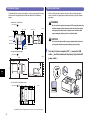
1
Remove the two pieces of tape as shown in the figure a, and then remove the
packing material with tape b.
Remove the packing material attached to the paper cassette
of the paper feeder.
Remove the tape as shown in the figure a, and then remove the packing material
with tape b.
a
a
b
b
a
2
Remove the two pieces of tape as shown in the figure a, and then remove the
packing material b.
Remove the tape that is securing the paper cassette.
To remove the packing material with tape, remove the two pieces of tape a, and
then remove the packing material together with the tape b.
b
Step
6
a
b
a
43
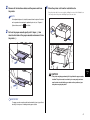
3
Pull out the paper cassette from the paper feeder.
4
Pull out the paper cassette until it stops a.
While holding the lock release lever of the rear paper guide,
slide the guide.
a
Hold the grips (A) with both hands, raise the front side of the paper cassette
slightly b, and then pull it out completely c as shown in the figure.
5
Remove the tape and packing material.
Remove the tape shown in the figure a.
c
b
Step
6
a
(A)
IMPORTANT
• Hold the paper cassette with both hands securely because the cassette is
Remove the packing material with tape b.
heavy.
• Place the removed paper cassette on a flat and stable surface.
• The paper cassette cannot be pulled out horizontally. If you try to pull it out
forcefully, this may result in damage to the paper cassette.
b
44
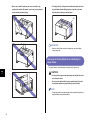
6
Place the paper feeder at the installation site.
7
Attach the cassette protective cover.
When carrying the paper feeder, hold the center of the lift handles on both sides
with both hands.
a
IMPORTANT
• Do not touch the connector (A) or feed roller (B) in the paper feeder. This
may result in damage to the printer or misfeeds.
b
(A)
(B)
IMPORTANT
Do not put your hand or things on the cassette protective cover, or shove
the cover hard. This may result in damage to the cassette protective cover.
• Do not install the paper feeder on a platform that may warp from the
weight of the printer and optional accessories, or where the printer is liable
to sink (such as a carpet or mat).
• Secure sufficient space around the paper feeder so that you can install the
printer and connect cords such as the power cord and interface cables.
45
Step
6
8
When installing the printer unit on the paper feeder, gently
set it down so that each surface of the printer unit is flush
with the front or side surfaces of the paper feeder.
Also, match the positioning pins (A) and connector (B) when setting the printer
unit.
10 Connect the interface cables except for the USB cable, and
connect the power cord.
11 Plug the power plug into the AC power outlet.
12 Connect the USB cable.
(B)
IMPORTANT
Be sure to turn the printer ON once when loading paper in the paper
cassette for the first time after installing the paper feeder.
NOTE
(A)
After installing the paper feeder, you have to specify the settings for the
(A)
optional accessories in the [Device Settings] sheet in the printer driver. You
can obtain the status of the optional accessories automatically by clicking
[Get Device Status] in the [Device Settings] sheet.
IMPORTANT
If the printer unit cannot be placed on the paper feeder properly, lift the
Loading Paper in the Paper Cassette
printer unit once, hold it horizontally, and place it again. If you try to set the
printer forcefully without lifting it, the connector and positioning pins may
be broken.
Step
6
9
Set the paper cassettes in the printer unit and paper feeder.
• When loading paper in portrait orientation: Width 210.0 to 297.0 mm; Length
210.0 to 431.8 mm
NOTE
If the optional duplex unit was previously installed, reinstall it on the printer.
For details on the procedure for installing the duplex unit, see "Installing
the Duplex Unit," on p. 47.
46
The paper cassette of the paper feeder (Cassette 2) can be loaded with up to
approximately 500 sheets of plain paper (60 - 90 g/m2) at sizes of A3, B4, A4,
B5, A5, Ledger (11 x 17), Legal, Letter, Executive, and 16K.
You can also load paper of the following custom paper sizes.
• When loading paper in landscape orientation: Width 210.0 to 297.0 mm;
Length 148.0 to 297.0 mm
For details on loading paper in the paper cassette of the paper feeder, see
"Chapter 2 Loading and Outputting Paper" in
User's Guide.
CD-ROM
Installing the Duplex Unit
The duplex unit is to be installed on the rear of the printer unit.
Installation Space
The dimensions of each part, foot positions, and the space required for using
the printer with the duplex unit installed are indicated in the following figures:
• Dimensions of the Printer
Front Surface
(mm)
93.8
184
172.2
121.6
40.6
88.6
Auxiliary Tray
Duplex Unit DU-67
32.6
438.7
WARNING
277
344
518
286.6
272
Tray
Extension
Auxiliary
Tray
Multi-purpose
Tray
Tray Extension
Auxiliary Tray
Sub-output Tray
• Required Peripheral Space
Be sure to turn the printer OFF, unplug the power plug, and then
disconnect all the interface cables and power cord from the printer
(mm)
before installing the duplex unit. Otherwise, the power cord or
interface cables may be damaged, resulting in a fire or electrical
430
100
544
718
200
shock.
100
1193.7
Step
6
325
Installing the Duplex Unit
The duplex unit is to be installed on the rear of the printer unit.
NOTE
The packing materials may be changed in form or position to be placed, or
may be added or removed without notice.
47
1
Turn the printer and computer OFF a, remove the USB
cable b, and then disconnect the power plug from the AC
power outlet c.
4
Install the duplex unit.
Push the duplex unit into the printer firmly and horizontally as shown in the figures.
c
b
a
a
2
Step
6
3
Remove all the interface cables and the power cord from
the printer.
Remove the duplex unit cover.
Hook your finger in the opening (A) of the duplex unit cover and remove it.
CAUTION
Push the duplex unit gently to avoid catching your hands, as this
may result in personal injury.
(A)
IMPORTANT
Keep the duplex unit cover. The duplex unit cover is required when the
duplex unit is removed.
48
IMPORTANT
If the duplex unit is not installed on the printer firmly (if there is any space
Installing the Network Board
between the rear of the printer and the duplex unit), this may result in misfeeds.
LICENCE AGREEMENT
Canon Software License Agreement
Read carefully the terms and conditions of use given below before using the
Software. By using the Software you agree to abide by the following terms
and conditions of use and enter into a legal agreement with Canon Inc.
("Canon"):
1. The title to and all rights of the Software and reproductions thereof are
reserved to Canon or Canon's licensors depending on the contents.
2. Canon hereby grants the Software's users ("the User") a non-exclusive
license to use the Software for use with certain Canon's Products
compatible with the Software.
3. The User shall not modify, alter, reverse engineer, decompile, disassemble
or otherwise change any part or all of the Software.
4. Canon, Canon's subsidiaries and Canon's licensors extend no warranties
of any kind as to the Software including but not limited to warranties of
fitness or usefulness for the User's particular purposes and lack of defects.
5. In no event shall Canon, Canon's subsidiaries or Canon's licensors be
liable for any direct, indirect or other losses or damages whatsoever arising
out of, incidental to or in connection with the use of the Software.
5
Connect the interface cables except for the USB cable, and
connect the power cord.
6
Plug the power plug into the AC power outlet.
7
Connect the USB cable.
6. The User shall not export, directly or indirectly, any part or all of the
Software without obtaining necessary approvals from the Japanese
government or the governments concerned.
The User shall not export or re-export any part of the Software to any
country the U.S. government prohibits exports to.
The User shall not export or re-export any part of the Software to any
person or organization the U.S. government prohibits any trade with.
The User shall not provide the Software for any person from the country
the U.S. government prohibits exports to.
NOTE
After installing the duplex unit, you have to specify the settings for the
optional accessories in the [Device Settings] sheet in the printer driver. You
can obtain the status of the optional accessories automatically by clicking
[Get Device Status] in the [Device Settings] sheet.
49
Step
6
CAUTION
Network Board
• Be sure to turn the printer OFF, unplug the power plug, and then
Install the network board in the expansion slot located on the rear of the
printer.
disconnect all the interface cables and power cord from the printer
before installing the network board. If a USB cable is connected, turn
the computer off, and then remove the USB cable. If you attempt to
install the network board when the printer is ON or any cable is
connected to the printer, this may result in an electrical shock.
ERR
LNK
100
sharp portion of the network board may result in personal injury.
Network board
*
• Be careful when handling the network board. Touching the edges or a
Guide booklet
Ferrite core
Screws
(2 pieces) (Only for NB-C1)
IMPORTANT
• The network board contains components that are sensitive to static
For NB-C2, a CD-ROM may be supplied with the network board.
electricity. Observe the following precautions when handling the network
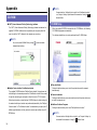
By installing the optional network board, you can use LBP3500 directly
connected to a network.
Connecting the network board on the printer directly to the computer
Client
LBP3500
(Network board installed)
board to prevent damage from static electricity.
- Touch a metal object to dissipate static electricity before handling the
network board.
- When handling the network board, do not touch anything that generates
static electricity such as the computer display.
- Do not touch the network board parts, printed wire, or connectors with
your hands.
Client
:TCP/IP
Step
6
NOTE
Connecting the printer to the computer via a print server
Client
- To prevent the network board from being affected by static electricity,
keep it in the protective bag until it is ready to be installed. The protective
bag is required after the network board is removed. Keep the protective
bag and do not discard of it.
Print server
This network board does not come with a LAN cable. A Category 5 twisted
pair cable is required for installing the network board and connecting the
printer to a network. Have cables or a hub ready as needed.
Client
LBP3500
(Network board installed)
:TCP/IP
:Usable Protocols
50
Parts and Their Functions
Installing the Network Board
Install the network board in the expansion slot of the printer using the
following procedure. A Phillips screwdriver is required for installing the
network board. Have a screwdriver ready in advance that matches the size of
the screws.
a
f
ERR
LNK
NOTE
100
This network board does not come with a LAN cable. A Category 5 twisted
pair cable is required for installing the network board and connecting the
e
d
c
b
a Printer Connector
Connects to the printer. Do not touch the connector directly with your
hands.
printer to a network. Have cables or a hub ready as needed.
1
b LAN Connector
Connects to a 10BASE-T/100BASE-TX LAN cable.
Turn the printer and computer OFF a, remove the USB
cable b, and then disconnect the power plug from the AC
power outlet c.
c 100 Indicator (Green)
Comes on when the network board is connected to the network by
100BASE-TX. Does not come on when connected by 10BASE-T.
c
d LNK Indicator (Green)
Comes on when the network board is connected to the network properly.
b
a
e ERR Indicator (Orange)
Comes on or blinks when the network board is not working properly.
f MAC Address
It is required when setting the IP address using the ARP/PING command.
It may be also required when installing the printer driver.
Step
6
IMPORTANT
a
The MAC address for NB-C1 can be found at the location of (A).
(A)
2
LN
ERR
K 10
0
Remove the power cord.
If there is not enough space to install the network board, move the printer to a
place where you can work easier.
51
ERR
LNK
100
3
IMPORTANT
Remove the screw and remove the protective plate for the
expansion slot.
• Do not touch the network board parts, printed wire, or connectors with
your hands.
• Insert the printer connector of the network board securely into the
connector inside the expansion slot.
5
Secure the top and bottom portions of the network board
with the two screws supplied with the network board.
IMPORTANT
The removed protective plate and screw are required when the network
board is removed. Keep them where they will not get lost.
4
Insert the network board into the expansion slot.
Hold the metal panel portions of the network board and insert the board while
aligning it with the guide rails inside the expansion slot.
Step
6
6
If you are using NB-C1, attach the ferrite core to the LAN
cable as shown in the figure.
Attach the ferrite core at 5 cm or less from the end of the connector which is
connected to the printer.
5 cm or less
52
7
Connect the LAN cable.
Connect a LAN cable that is compatible with the LAN connector of the network
board according to the network.
12 Make sure that the LNK indicator (green) on the network
board is on.
If the network board is connected by 10BASE-T, the board is working properly
when the LNK indicator is on.
If the network board is connected by 100BASE-TX, the board is working properly
when the LNK indicator and 100 indicator are on.
((A): 100 Indicator (B): LNK Indicator (C): ERR Indicator)
(A)
(B)
(C)
8
Connect the power cord.
9
Plug the power plug into the AC power outlet.
10 Connect the USB cable as needed.
If the network board is not working properly, turn the printer OFF, and then check
the LAN cable connection, hub performance, and network board installation. If
the network board does not operate properly even after turning the printer ON,
see "Chapter 4 Troubleshooting" in CD-ROM Network Guide.
11 Press " " of the power switch to turn the printer ON.
Step
6
53
Appendix
NOTE
For more details on "NetSpot Device Installer" and "Print Monitor Installer",
see "Chapter 2 Setting Up the Network Environment for Printing" in
CD-ROM
CD-ROM
Network Guide.
■ CAPT (Canon Advanced Printing Technology) software
The CAPT (Canon Advanced Printing Technology) software included on the
supplied CD-ROM is software that is required to print using this printer. Be
sure to install the CAPT software in the computer you are using.
CD-ROM Setup
When the supplied CD-ROM is inserted into the CD-ROM drive, the following
CD-ROM Setup appears automatically.
The software installation, etc. can be performed from CD-ROM Setup.
NOTE
Be sure to read the README file by clicking [
] on the installation
window before installing.
● Easy Installation
■ NetSpot Device Installer, Print Monitor Installer
The supplied CD-ROM includes "NetSpot Device Installer" that performs the
initial settings for the network protocol and "Print Monitor Installer" that creates
the port for connecting your computer to the printer on the TCP/IP network.
When the printer driver is installed from CD-ROM Setup, the initial settings for
the network and the port creation are performed automatically. Use "NetSpot
Device Installer" or "Print Monitor Installer" as needed when you specify the IP
address again manually or when you want to create a port without using CDROM Setup.
Clicking this button allows you to install the printer driver and the manuals
simultaneously.
● Custom Installation
Clicking this button allows you to select whether to install the printer driver only
or install the manuals only.
● Additional Software Programs
Clicking this button allows you to install "NetSpot Device Installer".
NOTE
For more details on "NetSpot Device Installer", see "Chapter 2 Setting Up
the Network Environment for Printing" in
54
CD-ROM
Network Guide.
● Display Manuals
Clicking this button displays the manuals for LBP3500 ([Getting Started
Guide], [User's Guide], [Network Guide], and [Remote UI Guide]).
Clicking [
] next to each guide displays the respective PDF manuals. To
display the manuals in PDF format, Adobe Reader/Adobe Acrobat Reader is
required. If Adobe Reader/Adobe Acrobat Reader is not installed on your
system, please download it from the Adobe Systems Incorporated website.
* The following PDF manuals are included in the "Manuals" folder in the
supplied CD-ROM.
Getting Started Guide: Manual_1.pdf
User's Guide: Manual_2.pdf
Network Guide: Manual_3.pdf
Remote UI Guide: Manual_4.pdf
● Exit
Clicking this button closes CD-ROM Setup.
NOTE
• If you are using Windows Vista and the [AutoPlay] dialog box appears,
click [Run AUTORUN.EXE].
• If CD-ROM Setup does not appear, display it using the following
procedures. (The CD-ROM drive name is indicated as "D:" in this manual.
The CD-ROM drive name may differ depending on the computer you are
using.)
- If you are using an operating system other than Windows Vista, select
[Run] from the [Start] menu, enter "D:\English\MInst.exe", and then click
[OK].
- If you are using Windows Vista, enter "D:\English\MInst.exe" in [Start
Search] under the [Start] menu, and then press the [ENTER] key on your
keyboard.
• If you are using Windows Vista and the [User Account Control] dialog box
appears, click [Allow].
55
CANON INC.
30-2, Shimomaruko 3-chome, Ohta-ku, Tokyo 146-8501, Japan
CANON MARKETING JAPAN INC.
16-6, Konan 2-chome, Minato-ku, Tokyo 108-8011, Japan
CANON U.S.A., INC.
One Canon Plaza, Lake Success, NY 11042, U.S.A.
CANON EUROPA N.V.
Bovenkerkerweg, 59-61, 1185 XB Amstelveen, The Netherlands
CANON CHINA CO. LTD.
15F Jinbao Building No.89, Jinbao Street, Dongcheng District, Beijing 100005, PRC
CANON SINGAPORE PTE LTD
1 HarbourFront Avenue, #04-01 Keppel Bay Tower, Singapore 098632
CANON AUSTRALIA PTY LTD
1 Thomas Holt Drive, North Ryde, Sydney NSW 2113, Australia
CANON GLOBAL WORLDWIDE SITES
http://www.canon.com/
FA7-9917 (050)
©2009 CANON INC.