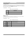
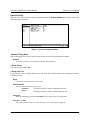
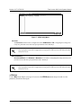
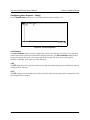
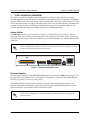
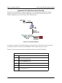
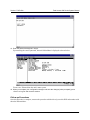
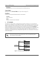
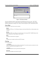
1
TOTAL ACCESS 600 SERIES
System Manual
4200641L1
Total Access 604,T1 TDM
4200641L2
Total Access 604, T1 ATM
4200644L1
Total Access 604, ADSL
4200642L1
Total Access 604, SDSL
4200643L1
Total Access 604, SHDSL
4200681L1
Total Access 608, T1 TDM
4200681L2
Total Access 608, T1 ATM
4200684L1
Total Access 608, ADSL
4200682L1
Total Access 608, SDSL
4200683L1
Total Access 608, SHDSL
4200612L1#TDM Total Access 612, T1 TDM
4200612L2#TDM Total Access 612, T1 TDM with Echo Cancellation, ADPCM Module
4200612L1#ATM
Total Access 612, T1 ATM
4200612L2
Total Access 612, SDSL
4200612L3
Total Access 612, SHDSL
4200616L1#TDM Total Access 616, T1 TDM
4200616L2#TDM Total Access 616, T1 TDM with Echo Cancellation, ADPCM Module
4200616L1#ATM
Total Access 616, T1 ATM
4200616L2
Total Access 616, SDSL
4200616L3
Total Access 616, SHDSL
4200624L1#TDM Total Access 624, T1 TDM
4200624L2#TDM Total Access 624, T1 TDM with Echo Cancellation, ADPCM Module
4200624L1#ATM
Total Access 624, T1 ATM
4200624L2
Total Access 624, SDSL
4200624L3
Total Access 624, SHDSL
61200624L1-1A
October 2002
Trademarks
Any brand names and product names included in this manual are trademarks, registered trademarks, or
trade names of their respective holders.
To the Holder of the Manual
The contents of this manual are current as of the date of publication. ADTRAN reserves the right to change
the contents without prior notice.
In no event will ADTRAN be liable for any special, incidental, or consequential damages or for
commercial losses even if ADTRAN has been advised thereof as a result of issue of this publication.
901 Explorer Boulevard
P.O. Box 140000
Huntsville, AL 35814-4000
Phone: (256) 963-8000
©2002 ADTRAN, Inc.
All Rights Reserved.
Printed in U.S.A.
About this Manual
This manual provides a complete description of the Total Access 600 Series system and system software.
The purpose of this manual is to provide the technician, system administrator, and manager with general
and specific information related to the planning, installation, operation, and maintenance of the Total
Access 600 Series. This manual is arranged so that needed information can be quickly and easily found.
The following is an overview of the contents.
Section 1
System Description . . . . . . . . . . . . . . . . . . . . . . . . . . . . . . . . . . . . . . . . 15
Provides managers with a system overview, features and benefits, and a list of resource
modules supported.
Section 2
Engineering Guidelines . . . . . . . . . . . . . . . . . . . . . . . . . . . . . . . . . . . . . 23
Provides equipment dimensions, power requirements, front panel design, rear panel
design, LEDs, and at-a-glance specifications.
Section 3
Network Turnup Procedure . . . . . . . . . . . . . . . . . . . . . . . . . . . . . . . . . . 39
Provides shipment contents list, grounding instructions, mounting options, and specifics
of supplying power to the unit.
Section 4
User Interface Guides (UIG) . . . . . . . . . . . . . . . . . . . . . . . . . . . . . . . . . 45
Provides detailed definitions, ranges, and default values for all ATM and TDM menu
options.
Section 5
Detail Level Procedures. . . . . . . . . . . . . . . . . . . . . . . . . . . . . . . . . . . . 355
Provides instructions on how to perform basic unit functions such as:
Connection
Log-in
Adding/removing telnet users and changing passwords
Setting IP parameters and verifying LAN communication
Telnet
Firmware upgrade
Saving and loading config files
Section 6
ADTRAN Utilities . . . . . . . . . . . . . . . . . . . . . . . . . . . . . . . . . . . . . . . . . 413
Provides instructions for configuring and using the ADTRAN Utilities software programs
including Telnet, VT100, and TFTP.
Section 7
MIB . . . . . . . . . . . . . . . . . . . . . . . . . . . . . . . . . . . . . . . . . . . . . . . . . . . . 423
Provides the MIB compilation order and the MIBs, Traps, and MIB Variables supported
by the unit.
61200624L1-1A
© 2002 ADTRAN, Inc.
3
Revision History
This is the first issue of this manual.
In this manual, unit refers to the Total Access 604, 608, 612, 616, and 624. If a statement
only applies to a particular unit, the unit will be specified by number.
4
© 2002 ADTRAN, Inc.
61200624L1-1A
Notes provide additional useful information.
Cautions signify information that could prevent service interruption.
Warnings provide information that could prevent damage to the equipment or
endangerment to human life.
Safety Instructions
When using your telephone equipment, please follow these basic safety precautions to reduce the risk of
fire, electrical shock, or personal injury:
1. Do not use this product near water, such as a bathtub, wash bowl, kitchen sink, laundry tub, in a
wet basement, or near a swimming pool.
2. Avoid using a telephone (other than a cordless-type) during an electrical storm. There is a remote
risk of shock from lightning.
3. Do not use the telephone to report a gas leak in the vicinity of the leak.
4. Use only the power cord, power supply, and/or batteries indicated in the manual. Do not dispose of
batteries in a fire. They may explode. Check with local codes for special disposal instructions.
Save These Important Safety Instructions
61200624L1-1A
© 2002 ADTRAN, Inc.
5
FCC regulations require that the following information be provided in this manual:
1. This equipment complies with Part 68 of FCC rules. On the back of the equipment housing is a
label showing the FCC registration number and ringer equivalence number (REN). If requested,
provide this information to the telephone company.
2. If this equipment causes harm to the telephone network, the telephone company may temporarily
discontinue service. If possible, advance notification is given; otherwise, notification is given as
soon as possible. The telephone company will advise the customer of the right to file a complaint
with the FCC.
3. The telephone company may make changes in its facilities, equipment, operations, or procedures
that could affect the proper operation of this equipment. Advance notification and the opportunity
to maintain uninterrupted service are given.
4. If experiencing difficulty with this equipment, please contact ADTRAN for repair and warranty
information. The telephone company may require this equipment to be disconnected from the
network until the problem is corrected or it is certain the equipment is not malfunctioning.
5. This unit contains no user-serviceable parts.
6. An FCC compliant telephone cord with a modular plug is provided with this equipment. This
equipment is designed to be connected to the telephone network or premises wiring using an FCC
compatible modular jack, which is Part 68 compliant.
7. The following information may be required when applying to the local telephone company for
leased line facilities.
Product
TA 600 Series T1
Products
Reg. Number
Service Type
REN/SOC
FIC
USOC
HDCUSA-44556-DE-N
1.544 Mbps - SF
1.544 Mbps - SF and B8ZS
1.544 Mbps - ESF
1.544 Mbps - ESF and B8ZS
6.0N
04DU9-BN
04DU9-DN
04DU9-1KN
04DU9-1SN
RJ-48
C
Analog Loop Start/
Ground Start Service
0.1B/9.0F
02LS2
02GS2
RJ-11C
TA 600 Series SDSL &
SHDSL Products
HDCUSA-44560-OT-N
Analog Loop Start/Ground
Start Service
0.1B/9.0F
02LS2
02GS2
RJ-11C
TA 600 Series ADSL
Products
US: HDCDL02B4200644L1
Analog Loop Start/Ground
Start Service
0.1B/9.0F
02LS2
02GS2
RJ-11C
ADSL Service
0.2B/9.0F
02LS2
8. The REN is useful in determining the quantity of devices you may connect to your telephone line
and still have all of those devices ring when your number is called. In most areas, the sum of the
RENs of all devices should not exceed five. To be certain of the number of devices you may
connect to your line as determined by the REN, call your telephone company to determine the
maximum REN for your calling area.
9. This equipment may not be used on coin service provided by the telephone company. Connection
to party lines is subject to state tariffs. Contact your state public utility commission or corporation
commission for information.
6
© 2002 ADTRAN, Inc.
61200624L1-1A
Affidavit Requirements for Connection to Digital Services
•
•
•
An affidavit is required to be given to the telephone company whenever digital terminal equipment
without encoded analog content and billing protection is used to transmit digital signals containing
encoded analog content which are intended for eventual conversion into voiceband analog signals and
transmitted on the network.
The affidavit shall affirm that either no encoded analog content or billing information is being
transmitted or that the output of the device meets Part 68 encoded analog content or billing protection
specifications.
End user/customer will be responsible for filing an affidavit with the local exchange carrier when
connecting unprotected customer premise equipment (CPE) to 1.544 Mbps or subrate digital services.
Until such time as subrate digital terminal equipment is registered for voice applications, the affidavit
requirement for subrate services is waived.
61200624L1-1A
© 2002 ADTRAN, Inc.
7
Affidavit for Connection of Customer Premises Equipment
to 1.544 Mbps and/or Subrate Digital Services
For the work to be performed in the certified territory of ___________________ (telco name)
State of ________________
County of ________________
I, _______________________ (name), ____________________________________ (business address),
____________________ (telephone number) being duly sworn, state:
I have responsibility for the operation and maintenance of the terminal equipment to be connected
to 1.544 Mbps and/or ________ subrate digital services. The terminal equipment to be connected
complies with Part 68 of the FCC rules except for the encoded analog content and billing protection
specifications. With respect to encoded analog content and billing protection:
( ) I attest that all operations associated with the establishment, maintenance, and adjustment of the digital
CPE with respect to analog content and encoded billing protection information continuously complies
with Part 68 of the FCC Rules and Regulations.
( ) The digital CPE does not transmit digital signals containing encoded analog content or billing
information which is intended to be decoded within the telecommunications network.
( ) The encoded analog content and billing protection is factory set and is not under the control of the
customer.
I attest that the operator(s)/maintainer(s) of the digital CPE responsible for the establishment,
maintenance, and adjustment of the encoded analog content and billing information has (have) been
trained to perform these functions by successfully having completed one of the following (check
appropriate blocks):
( ) A. A training course provided by the manufacturer/grantee of the equipment used to encode analog
signals; or
( ) B. A training course provided by the customer or authorized representative, using training materials
and instructions provided by the manufacturer/grantee of the equipment used to encode analog
signals; or
( ) C. An independent training course (e.g., trade school or technical institution) recognized by the
manufacturer/grantee of the equipment used to encode analog signals; or
( ) D. In lieu of the preceding training requirements, the operator(s)/maintainer(s) is (are) under the
control of a supervisor trained in accordance with _________ (circle one) above.
8
© 2002 ADTRAN, Inc.
61200624L1-1A
I agree to provide ______________________ (telco’s name) with proper documentation to
demonstrate compliance with the information as provided in the preceding paragraph, if so
requested.
_________________________________Signature
_________________________________Title
_________________________________ Date
Transcribed and sworn to before me
This ________ day of _______________, _______
_________________________________
Notary Public
My commission expires:
_________________________________
61200624L1-1A
© 2002 ADTRAN, Inc.
9
Federal Communications Commission Radio Frequency Interference Statement
This equipment has been tested and found to comply with the limits for a Class A digital device, pursuant
to Part 15 of the FCC Rules. These limits are designed to provide reasonable protection against harmful
interference when the equipment is operated in a commercial environment. This equipment generates,
uses, and can radiate radio frequency energy and, if not installed and used in accordance with the
instruction manual, may cause harmful interference to radio frequencies. Operation of this equipment in a
residential area is likely to cause harmful interference in which case the user will be required to correct the
interference at his own expense.
Shielded cables must be used with this unit to ensure compliance with Class A FCC limits.
Changes or modifications to this unit not expressly approved by the party responsible
for compliance could void the user’s authority to operate the equipment.
10
© 2002 ADTRAN, Inc.
61200624L1-1A
Industry Canada Compliance Information
Notice: The Industry Canada label applied to the product (identified by the Industry Canada logo or the
“IC:” in front of the certification/registration number) signifies that the Industry Canada technical
specifications were met.
Notice: The Ringer Equivalence Number (REN) for this terminal equipment is supplied in the
documentation or on the product labeling/markings. The REN assigned to each terminal device indicates
the maximum number of terminals that can be connected to a telephone interface. The termination on an
interface may consist of any combination of devices subject only to the requirement that the sum of the
RENs of all the devices should not exceed five (5).
Canadian Emissions Requirements
This digital apparatus does not exceed the Class A limits for radio noise emissions from digital apparatus
as set out in the interference-causing equipment standard entitled “Digital Apparatus,” ICES-003 of the
Department of Communications.
Cet appareil numérique respecte les limites de bruits radioelectriques applicables aux appareils numériques
de Class A prescrites dans la norme sur le materiel brouilleur: “Appareils Numériques,” NMB-003 edictee
par le ministre des Communications.
61200624L1-1A
© 2002 ADTRAN, Inc.
11
Warranty and Customer Service
ADTRAN will repair and return this product within ten years from the date of shipment if it does not meet
its published specifications or fails while in service. For detailed warranty, repair, and return information
refer to the ADTRAN Equipment Warranty and Repair and Return Policy Procedure.
Return Material Authorization (RMA) is required prior to returning equipment to ADTRAN.
For service, RMA requests, or further information, contact one of the numbers listed at the end of this
section.
LIMITED PRODUCT WARRANTY
ADTRAN warrants that for ten years from the date of shipment to Customer, all products manufactured by
ADTRAN will be free from defects in materials and workmanship. ADTRAN also warrants that products
will conform to the applicable specifications and drawings for such products, as contained in the Product
Manual or in ADTRAN's internal specifications and drawings for such products (which may or may not be
reflected in the Product Manual). This warranty only applies if Customer gives ADTRAN written notice of
defects during the warranty period. Upon such notice, ADTRAN will, at its option, either repair or replace
the defective item. If ADTRAN is unable, in a reasonable time, to repair or replace any equipment to a
condition as warranted, Customer is entitled to a full refund of the purchase price upon return of the
equipment to ADTRAN. This warranty applies only to the original purchaser and is not transferable
without ADTRAN's express written permission. This warranty becomes null and void if Customer
modifies or alters the equipment in any way, other than as specifically authorized by ADTRAN.
EXCEPT FOR THE LIMITED WARRANTY DESCRIBED ABOVE, THE FOREGOING
CONSTITUTES THE SOLE AND EXCLUSIVE REMEDY OF THE CUSTOMER AND THE
EXCLUSIVE LIABILITY OF ADTRAN AND IS IN LIEU OF ANY AND ALL OTHER WARRANTIES
(EXPRESSED OR IMPLIED). ADTRAN SPECIFICALLY DISCLAIMS ALL OTHER WARRANTIES,
INCLUDING (WITHOUT LIMITATION), ALL WARRANTIES OF MERCHANTABILITY AND
FITNESS FOR A PARTICULAR PURPOSE. SOME STATES DO NOT ALLOW THE EXCLUSION
OF IMPLIED WARRANTIES, SO THIS EXCLUSION MAY NOT APPLY TO CUSTOMER.
In no event will ADTRAN or its suppliers be liable to the Customer for any incidental, special, punitive,
exemplary or consequential damages experienced by either the Customer or a third party (including, but
not limited to, loss of data or information, loss of profits, or loss of use). ADTRAN is not liable for
damages for any cause whatsoever (whether based in contract, tort, or otherwise) in excess of the amount
paid for the item. Some states do not allow the limitation or exclusion of liability for incidental or
consequential damages, so the above limitation or exclusion may not apply to the Customer.
12
© 2002 ADTRAN, Inc.
61200624L1-1A
Customer Service, Product Support Information, and Training
ADTRAN will repair and return this product if within ten years from the date of shipment the product
does not meet its published specification or the product fails while in service.
A return material authorization (RMA) is required prior to returning equipment to ADTRAN. For service,
RMA requests, training, or more information, use the contact information given below.
Repair and Return
If you determine that a repair is needed, please contact our Customer and Product Service (CAPS)
department to have an RMA number issued. CAPS should also be contacted to obtain information
regarding equipment currently in house or possible fees associated with repair.
CAPS Department
(256) 963-8722
Identify the RMA number clearly on the package (below address), and return to the following address:
ADTRAN Customer and Product Service
901 Explorer Blvd. (East Tower)
Huntsville, Alabama 35806
RMA # _____________
Pre-Sales Inquiries and Applications Support
Your reseller should serve as the first point of contact for support. If additional pre-sales support is needed,
the ADTRAN Support web site provides a variety of support services such as a searchable knowledge
base, latest product documentation, application briefs, case studies, and a link to submit a question to an
Applications Engineer. All of this, and more, is available at:
http://support.adtran.com
When needed, further pre-sales assistance is available by calling our Applications Engineering
Department.
Applications Engineering (800) 615-1176
61200624L1-1A
© 2002 ADTRAN, Inc.
13
Post-Sale Support
Your reseller should serve as the first point of contact for support. If additional support is needed, the
ADTRAN Support web site provides a variety of support services such as a searchable knowledge base,
updated firmware releases, latest product documentation, service request ticket generation and
trouble-shooting tools. All of this, and more, is available at:
http://support.adtran.com
When needed, further post-sales assistance is available by calling our Technical Support Center. Please
have your unit serial number available when you call.
Technical Support
(888) 4ADTRAN
Installation and Maintenance Support
The ADTRAN Custom Extended Services (ACES) program offers multiple types and levels of installation
and maintenance services which allow you to choose the kind of assistance you need. This support is
available at:
http://www.adtran.com/aces
For questions, call the ACES Help Desk.
ACES Help Desk
(888) 874-ACES (2237)
Training
The Enterprise Network (EN) Technical Training Department offers training on our most popular products.
These courses include overviews on product features and functions while covering applications of
ADTRAN's product lines. ADTRAN provides a variety of training options, including customized training
and courses taught at our facilities or at your site. For more information about training, please contact your
Territory Manager or the Enterprise Training Coordinator.
14
Training Phone
(800) 615-1176, ext. 7500
Training Fax
(256) 963-6700
Training Email
[email protected]
© 2002 ADTRAN, Inc.
61200624L1-1A
SYSTEM DESCRIPTION
CONTENTS
System Overview. . . . . . . . . . . . . . . . . . . . . . . . . . . . . . . . . . . . . . . . . . . . . . . . . . . . . . . . . . . . . . . . . . . 17
Features and Benefits . . . . . . . . . . . . . . . . . . . . . . . . . . . . . . . . . . . . . . . . . . . . . . . . . . . . . . . . . . . . . . .
Configuration and Management . . . . . . . . . . . . . . . . . . . . . . . . . . . . . . . . . . . . . . . . . . . . . . . . . . . . .
Firmware Upgradeable . . . . . . . . . . . . . . . . . . . . . . . . . . . . . . . . . . . . . . . . . . . . . . . . . . . . . . . . . . . .
Network Interface . . . . . . . . . . . . . . . . . . . . . . . . . . . . . . . . . . . . . . . . . . . . . . . . . . . . . . . . . . . . . . . .
ATM Support . . . . . . . . . . . . . . . . . . . . . . . . . . . . . . . . . . . . . . . . . . . . . . . . . . . . . . . . . . . . . . . . . . . .
Frame Relay Support . . . . . . . . . . . . . . . . . . . . . . . . . . . . . . . . . . . . . . . . . . . . . . . . . . . . . . . . . . . . .
Analog Ports . . . . . . . . . . . . . . . . . . . . . . . . . . . . . . . . . . . . . . . . . . . . . . . . . . . . . . . . . . . . . . . . . . . .
Routing Capability . . . . . . . . . . . . . . . . . . . . . . . . . . . . . . . . . . . . . . . . . . . . . . . . . . . . . . . . . . . . . . . .
Security . . . . . . . . . . . . . . . . . . . . . . . . . . . . . . . . . . . . . . . . . . . . . . . . . . . . . . . . . . . . . . . . . . . . . . . .
V.35 DTE Interface . . . . . . . . . . . . . . . . . . . . . . . . . . . . . . . . . . . . . . . . . . . . . . . . . . . . . . . . . . . . . . .
Integrated Components. . . . . . . . . . . . . . . . . . . . . . . . . . . . . . . . . . . . . . . . . . . . . . . . . . . . . . . . . . . .
Testing . . . . . . . . . . . . . . . . . . . . . . . . . . . . . . . . . . . . . . . . . . . . . . . . . . . . . . . . . . . . . . . . . . . . . . . .
17
17
18
18
18
18
18
18
19
19
19
19
IAD Systems. . . . . . . . . . . . . . . . . . . . . . . . . . . . . . . . . . . . . . . . . . . . . . . . . . . . . . . . . . . . . . . . . . . . . . .
T1 . . . . . . . . . . . . . . . . . . . . . . . . . . . . . . . . . . . . . . . . . . . . . . . . . . . . . . . . . . . . . . . . . . . . . . . . . . . .
ADSL. . . . . . . . . . . . . . . . . . . . . . . . . . . . . . . . . . . . . . . . . . . . . . . . . . . . . . . . . . . . . . . . . . . . . . . . . .
SDSL. . . . . . . . . . . . . . . . . . . . . . . . . . . . . . . . . . . . . . . . . . . . . . . . . . . . . . . . . . . . . . . . . . . . . . . . . .
SHDSL . . . . . . . . . . . . . . . . . . . . . . . . . . . . . . . . . . . . . . . . . . . . . . . . . . . . . . . . . . . . . . . . . . . . . . . .
20
20
20
20
20
Resource Modules. . . . . . . . . . . . . . . . . . . . . . . . . . . . . . . . . . . . . . . . . . . . . . . . . . . . . . . . . . . . . . . . . . 21
61200624L1-1A
© 2002 ADTRAN, Inc.
15
Section 1 System Description
16
Total Access 600 Series System Manual
© 2002 ADTRAN, Inc.
61200624L1-1A
Total Access 600 Series System Manual
1.
Section 1 System Description
SYSTEM OVERVIEW
The products of the Total Access 600 Series are Integrated Access Devices (IAD) designed for
cost-effective deployment of voice and data services at the customer premises. The Total Access 600
Series benefits integrated communications providers (such as CLECs, ILECs, and ISPs) who require a
customer premises device with integrated voice and data functions, and provides a viable migration path
from TDM to packet-based technology. These IADs support applications such as VoDSL and VoATM.
The Total Access 600 Series features remote management, built-in IP router, and life-line voice backup.
An optional battery backup is also available for many of the models. The units include a Nx56/64 V.35
interface, 10/100BaseT interface, FXS ports, and network interfaces (T1, ADSL, SDSL, and SHDSL). The
last two digits of the product name indicate the number of on-board FXS ports. The Total Access 604
contains four FXS ports, the Total Access 608 contains eight FXS ports, etc. The units can provision, test,
and provide status for any of the voice and data interfaces. All connections are made via the rear panel.
This line of IADs includes both the ATM and TDM versions of the Total Access 604/608/612/616/624.
Until now, the Total Access TDM units have been running firmware version A.03.XX. Recently, A.04.XX
has been released to support the TDM Total Access IADs. The development of A.04.XX code is a
significant step in the evolution of the Total Access product line, as it allows all Total Access family
members to share the same base code. This means that features and fixes are more easily implemented and
are propagated across the product line. The TDM User Interface Guide section of this manual represents
the A.04 firmware. There are two possible upgrade paths: (1) Upgrading from A.03 to A.04 directly (2)
Upgrading from A.03 to A.03.90 (Transition Build) to A.04.
Upgrading from A.03 to A.03.90 (Transition Build) to A.04 will save the unit’s
configuration. Upgrading from A.03 to A.04 directly (or from A.04 to A.03 directly) will
erase the unit’s configuration. See DLP-016, A.03 to A.04 Firmware Upgrade for more
details.
Units manufactured after October 2002 will not be compatible with some older
versions of Total Access 612, 616, and 624 software. Refer to the following
information if an older version of software is to be loaded into the unit. For TDM
applications, please use software revision A.03.58 or later. For ATM applications,
software revision D.01.30 or later is required. Using incompatible software will
cause the unit to malfunction. For more information or technical assistance, please
call ADTRAN Technical Support at 888-4ADTRAN. Please have the unit serial
number available when contacting Technical Support.
2.
FEATURES AND BENEFITS
Below is a list of unit features and benefits. Some features are model-dependent.
Configuration and Management
•
•
•
•
VT100 Emulation via the Craft port
Telnet
SNMP
Support for VoDSL gateway management systems and firmware download
61200624L1-1A
© 2002 ADTRAN, Inc.
17
Section 1 System Description
Total Access 600 Series System Manual
Firmware Upgradeable
•
•
TFTP download
XMODEM via Craft port
Network Interface
•
•
•
•
T1
ADSL
SDSL
SHDSL
ATM Support
•
•
•
•
•
•
•
•
•
AAL2 (voice), AAL5 (data, voice)
6 PVCs (1 voice, 5 data)
RFC 1483 (multiprotocol over ATM)
PPPoA (RFC 2364)
QoS Support: VBR-rt (voice), UBR (data)
I.610 F5 OAM loopback
G.165/G.168 echo cancellation, 8 ms echo tail
Voice Codes: PCM (G.711), 32k ADPCM (G.726)
Idle channel suppression
Frame Relay Support
•
•
Copper Mountain CE fragmentation support
FRF.5 and FRF.8 support (V.35)
Analog Ports
•
Analog FXS ports per TR-57, 50-Pin Amp (number of ports is unit dependent)
•
•
Supports popular CLASSTM features
Modes: FXS Loop Start, FXS Ground Start, TR08 Single, TR08 UVG, DP0, Tandem (E&M)
•
•
•
•
•
•
Assured DialtoneTM Lifeline POTS port
Unbalanced ringing, 5 REN per port not to exceed 35 REN (Total Access 612/616/624)
Balanced ringing, 3.75 REN per port not to exceed 15 REN (Total Access 604/608)
Fixed 88 Vrms ringer (Total access 612/616/624)
Programmable ring voltage from 45 Vrms-62 Vrms (Total Access 604/608)
Distance up to 1000 feet
Routing Capability
•
18
Ethernet: 10/100BaseT (RJ-45)
© 2002 ADTRAN, Inc.
61200624L1-1A
Total Access 600 Series System Manual
•
•
•
•
•
Section 1 System Description
IEEE 802.3 and 802.1D (MAC Bridging)
IP Support: TCP, RIP V1, RIP V2, UDP, ICMP, ARP, UDP Relay, SYSLOG
PPP Support: LCP, IPCP, BCP
DHCP Server to LAN, DHCP from network (NAT)
Copper Mountain Compatible
Security
•
•
•
•
•
•
PAP, CHAP, EAP, and Radius
NAT with multi-point to single-point
Future support of NAT multi-point to multi-point
PAT with DHCP
Filtering (Pattern, IP, Bridge)
Password protection
V.35 DTE Interface
•
•
•
Data Rate: Nx56 or Nx64 kbps (N=1 to 24)
Electrical and Mechanical: CCITT V.35, 34-pin
Frame Relay (FRF.5, FRF.8 capable)
Integrated Components
•
•
•
•
•
•
IP router
Life-line voice backup
Network connection
10/100 BaseT connection
V.35 Nx56/64 DTE interface
Craft port
Testing
•
•
•
Local/Remote Loopbacks
Payloads
FXS Tests
61200624L1-1A
© 2002 ADTRAN, Inc.
19
Section 1 System Description
3.
Total Access 600 Series System Manual
IAD SYSTEMS
The units support a variety of WAN technologies. The units are listed below in categories based on these
technologies.
T1
•
•
•
•
•
•
•
•
•
•
•
•
•
P/N 4200641L1
P/N 4200641L2
P/N 4200681L1
P/N 4200681L2
P/N 4200612L1#TDM
P/N 4200612L1#ATM
P/N 4200612L2#TDM
P/N 4200616L1#TDM
P/N 4200616L1#ATM
P/N 4200616L2#TDM
P/N 4200624L1#TDM
P/N 4200624L1#ATM
P/N 4200624L2#TDM
Total Access 604 T1 TDM
Total Access 604 T1 ATM
Total Access 608 T1 TDM
Total Access 608 T1 ATM
Total Access 612 T1 TDM
Total Access 612 T1 ATM
Total Access 612 T1 TDM with Echo Cancellation, ADPCM Module
Total Access 616 T1 TDM
Total Access 616 T1 ATM
Total Access 616 T1 TDM with Echo Cancellation, ADPCM Module
Total Access 624 T1 TDM
Total Access 624 T1 ATM
Total Access 624 T1 TDM with Echo Cancellation, ADPCM Module
ADSL
•
•
P/N 4200644L1
P/N 4200684L1
Total Access 604 ADSL
Total Access 608 ADSL
SDSL
•
•
•
•
•
P/N 4200642L1
P/N 4200682L1
P/N 4200612L2
P/N 4200616L2
P/N 4200624L2
Total Access 604 SDSL
Total Access 608 SDSL
Total Access 612 SDSL
Total Access 616 SDSL
Total Access 624 SDSL
SHDSL
•
•
•
•
•
20
P/N 4200643L1
P/N 4200683L1
P/N 4200612L3
P/N 4200616L3
P/N 4200624L3
Total Access 604 SHDSL
Total Access 608 SHDSL
Total Access 612 SHDSL
Total Access 616 SHDSL
Total Access 624 SHDSL
© 2002 ADTRAN, Inc.
61200624L1-1A
Total Access 600 Series System Manual
4.
Section 1 System Description
RESOURCE MODULES
Echo Canceller with ADPCM
The Echo Canceller Module provides G.165/G.168 echo cancellation for voice over ATM applications and
is available with Adaptive Differential Pulse Code Modulation (ADPCM). ADPCM is a speech coding
method which uses fewer bits than traditional Pulse Code Modulation (PCM), allowing the user to get
more analog voice calls on less bandwidth. Echo cancellation and ADPCM resources are built into all
Total Access 604/608 units and the third generation Total Access 612/616/624 units (P/N 1203612L1,
1203616L1, and 1203624L1). The Total Access 612/616/624 T1 TDM units (P/N 4200612L1#TDM,
4200616L1#TDM, and 4200624L1#TDM) may be upgraded to include echo cancellation via three
methods:
1. The upgrade package may be purchased from ADTRAN. This package includes EC/ADPCM (P/N
1200613L1) and the ADTRAN installation and test. If this package is ordered, the customer must send
their TDM 612/616/624 unit back to ADTRAN. Once received the EC/ADPCM module is installed
along with the latest VoATM firmware. The upgraded unit is then tested and returned to the customer.
Please call ADTRAN CAPs department at 800-9-ADTRAN extension 7722 for this service.
2. An EC/ADPCM module may be purchased separately and installed by the customer. The latest VoATM
firmware may be obtained from the ADTRAN website (http://www.ADTRAN.com) and loaded into the
unit by the customer. For more detailed instructions, refer to DLP-015 TDM to ATM Upgrade.
3. For customers who plan to initially operate a TDM application, but eventually upgrade to an ATM
application, a Total Access 612/616/624 unit may be purchased with the EC/ADPCM card installed
(P/N 4200612L2#TDM, 4200616L2#TDM, 4200642L2#TDM). When the circuit is converted to ATM,
the ATM firmware must be obtained from the ADTRAN website (http://www.ADTRAN.com) and loaded
into the unit by the customer. For more detailed instructions, refer to DLP-015 TDM to ATM Upgrade.
61200624L1-1A
© 2002 ADTRAN, Inc.
21
Section 1 System Description
22
Total Access 600 Series System Manual
© 2002 ADTRAN, Inc.
61200624L1-1A
ENGINEERING GUIDELINES
CONTENTS
Equipment Dimensions . . . . . . . . . . . . . . . . . . . . . . . . . . . . . . . . . . . . . . . . . . . . . . . . . . . . . . . . . . . 25
Total Access 604/608 . . . . . . . . . . . . . . . . . . . . . . . . . . . . . . . . . . . . . . . . . . . . . . . . . . . . . . . . . 25
Total Access 612/616/624. . . . . . . . . . . . . . . . . . . . . . . . . . . . . . . . . . . . . . . . . . . . . . . . . . . . . . 25
Power Requirements . . . . . . . . . . . . . . . . . . . . . . . . . . . . . . . . . . . . . . . . . . . . . . . . . . . . . . . . . . . . 25
AC Power . . . . . . . . . . . . . . . . . . . . . . . . . . . . . . . . . . . . . . . . . . . . . . . . . . . . . . . . . . . . . . . . . . 25
Reviewing the Front Panel Design . . . . . . . . . . . . . . . . . . . . . . . . . . . . . . . . . . . . . . . . . . . . . . . . . 26
Total Access 604/608 . . . . . . . . . . . . . . . . . . . . . . . . . . . . . . . . . . . . . . . . . . . . . . . . . . . . . . . . . 26
Total Access 612/616/624. . . . . . . . . . . . . . . . . . . . . . . . . . . . . . . . . . . . . . . . . . . . . . . . . . . . . . 26
Front Panel LEDs . . . . . . . . . . . . . . . . . . . . . . . . . . . . . . . . . . . . . . . . . . . . . . . . . . . . . . . . . . . . 27
Reviewing the Rear Panel Design . . . . . . . . . . . . . . . . . . . . . . . . . . . . . . . . . . . . . . . . . . . . . . . . . . 30
Voice Connection . . . . . . . . . . . . . . . . . . . . . . . . . . . . . . . . . . . . . . . . . . . . . . . . . . . . . . . . . . . . 31
Life Line Connection . . . . . . . . . . . . . . . . . . . . . . . . . . . . . . . . . . . . . . . . . . . . . . . . . . . . . . . . . . 32
NTWK Connection . . . . . . . . . . . . . . . . . . . . . . . . . . . . . . . . . . . . . . . . . . . . . . . . . . . . . . . . . . . 32
Craft Port. . . . . . . . . . . . . . . . . . . . . . . . . . . . . . . . . . . . . . . . . . . . . . . . . . . . . . . . . . . . . . . . . . . 34
10/100BaseT Connection . . . . . . . . . . . . . . . . . . . . . . . . . . . . . . . . . . . . . . . . . . . . . . . . . . . . . . 35
V.35 Connection . . . . . . . . . . . . . . . . . . . . . . . . . . . . . . . . . . . . . . . . . . . . . . . . . . . . . . . . . . . . . 35
Battery Backup Connection. . . . . . . . . . . . . . . . . . . . . . . . . . . . . . . . . . . . . . . . . . . . . . . . . . . . . 36
AC Power Connection. . . . . . . . . . . . . . . . . . . . . . . . . . . . . . . . . . . . . . . . . . . . . . . . . . . . . . . . . 36
DB-9 to RJ Adapter . . . . . . . . . . . . . . . . . . . . . . . . . . . . . . . . . . . . . . . . . . . . . . . . . . . . . . . . . . . . . . 36
At-A-Glance Specifications . . . . . . . . . . . . . . . . . . . . . . . . . . . . . . . . . . . . . . . . . . . . . . . . . . . . . . . 37
FIGURES
Figure 1.
Figure 2.
Figure 3.
Figure 4.
Figure 5.
Total Access 604/608 Front Panel . . . . . . . . . . . . . . . . . . . . . . . . . . . . . . . . . . . . . . . . .
Total Access 612/616/624 Front Panel . . . . . . . . . . . . . . . . . . . . . . . . . . . . . . . . . . . . .
Total Access 604/608 Rear Panel . . . . . . . . . . . . . . . . . . . . . . . . . . . . . . . . . . . . . . . . .
Total Access 612/616/624 Rear Panel. . . . . . . . . . . . . . . . . . . . . . . . . . . . . . . . . . . . . .
Voice Connector Pin Assignments. . . . . . . . . . . . . . . . . . . . . . . . . . . . . . . . . . . . . . . . .
61200624L1-1A
© 2002 ADTRAN, Inc.
26
26
30
30
31
23
Section 2 Engineering Guidelines
Total Access 600 Series System Manual
TABLES
Table 1.
Table 2.
Table 3.
Table 4.
Table 5.
Table 6.
Table 7.
Table 8.
Table 9.
Table 10.
Table 11.
Table 12.
Table 13.
Table 14.
24
AC Power Requirements . . . . . . . . . . . . . . . . . . . . . . . . . . . . . . . . . . . . . . . . . . . . . . . . . 25
Total Access 604/608 TDM Front Panel LEDs . . . . . . . . . . . . . . . . . . . . . . . . . . . . . . . . 27
Total Access 612/616/624 TDM Front Panel LEDs . . . . . . . . . . . . . . . . . . . . . . . . . . . . 28
Total Access 604/608/612/616/624 ATM Front Panel LEDs . . . . . . . . . . . . . . . . . . . . . . 29
LIFE LINE Connection Pinout . . . . . . . . . . . . . . . . . . . . . . . . . . . . . . . . . . . . . . . . . . . . . . 32
T1 NTWK Connection Pinout . . . . . . . . . . . . . . . . . . . . . . . . . . . . . . . . . . . . . . . . . . . . . 32
ADSL Network Connection Pinout . . . . . . . . . . . . . . . . . . . . . . . . . . . . . . . . . . . . . . . . . 33
SDSL Network Connection Point . . . . . . . . . . . . . . . . . . . . . . . . . . . . . . . . . . . . . . . . . . 33
SHDSL Network Connection Pinout . . . . . . . . . . . . . . . . . . . . . . . . . . . . . . . . . . . . . . . . 33
CRAFT Pinout . . . . . . . . . . . . . . . . . . . . . . . . . . . . . . . . . . . . . . . . . . . . . . . . . . . . . . . . . 34
10/100BaseT Pinout . . . . . . . . . . . . . . . . . . . . . . . . . . . . . . . . . . . . . . . . . . . . . . . . . . . . 35
V.35 Interface Pinout . . . . . . . . . . . . . . . . . . . . . . . . . . . . . . . . . . . . . . . . . . . . . . . . . . . . 35
DB-9 to RJ Adapter Pinout . . . . . . . . . . . . . . . . . . . . . . . . . . . . . . . . . . . . . . . . . . . . . . . 36
Specifications . . . . . . . . . . . . . . . . . . . . . . . . . . . . . . . . . . . . . . . . . . . . . . . . . . . . . . . . . 37
© 2002 ADTRAN, Inc.
61200624L1-1A
Total Access 600 Series System Manual
1.
Section 2 Engineering Guidelines
EQUIPMENT DIMENSIONS
Total Access 604/608
The Total Access 604/608 units measure 11.25” W, 7.5” D, and 2” H and come equipped for table top or
wall mount use.
Total Access 612/616/624
The Total Access 612/616/624 units measure 17” W, 8.5” D, and 1.75” H and come equipped for table top
or wall mount use. They can also be mounted in a 19” or 23” rack with the purchase of mounting brackets
(P/N1200627L1 - 19” and P/N1200627 L2- 23”).
2.
POWER REQUIREMENTS
AC Power
The units vary in their maximum power consumption and current draw. See Table 1 for details.
Table 1. AC Power Requirements
Maximum Power
Consumption
Maximum Current
Draw
Total Access 604
90-125 VAC 60 Hz
300 mA
Total Access 608
90-125 VAC 60 Hz
300 mA
Total Access 612
90-120 VAC 60 Hz
1.3 A
Total Access 616
90-120 VAC 60 Hz
1.3 A
Total Access 624
90-120 VAC 60 Hz
1.3 A
Product
61200624L1-1A
© 2002 ADTRAN, Inc.
25
Section 2 Engineering Guidelines
3.
Total Access 600 Series System Manual
REVIEWING THE FRONT PANEL DESIGN
Total Access 604/608
The front panels of the Total Access 604/608 units are identical. Figure 1 shows the Total Access 608 as a
representative of both models. Table 2 on page 27 and Table 4 on page 29 describe the LEDs and their
functions.
Figure 1. Total Access 604/608 Front Panel
Total Access 612/616/624
The front panels of the Total Access 612/616/624 units are identical. Figure 2 shows the Total Access 612
as a representative of all three models. Table 3 on page 28 and Table 4 on page 29 describe the LEDs and
their functions.
Figure 2. Total Access 612/616/624 Front Panel
26
© 2002 ADTRAN, Inc.
61200624L1-1A
Total Access 600 Series System Manual
Section 2 Engineering Guidelines
Front Panel LEDs
The front panel provides eight status LEDs to monitor operation and activity. The LED functionality varies
based on product and software load (TDM vs ATM). The following tables provide LED activity
explanations for the various combinations.
Table 2. Total Access 604/608 TDM Front Panel LEDs
For these LEDs...
This color light...
Indicates that...
TX/RX
Off
There is no data traffic on the LAN.
Green (blinking)
There is data traffic on the LAN.
Off
The physical link is down, there is no Ethernet
connection.
Green (solid)
There is link integrity on the LAN (physical link is up).
Off
No data traffic is being received on the V.35.
Green (blinking)
Data is being received on the V.35.
Off
No data traffic is being transmitted on the V.35.
Green (blinking)
Data is being transmitted on the V.35.
Red (solid)
The T1 is in red alarm or T1 sync loss has occurred.
Yellow (solid)
The T1 is in test.
Green (solid)
Layer 2 is up.
Off
The T1 is down.
Green (blinking)
The phone is off hook.
Green (solid)
The T1 is up and the phone is on hook.
Off
AC has failed and no battery.
Green (solid)
AC is operational and battery is good.
Red/Green
(alternating)
AC is operational and battery is bad.
Amber (solid)
AC has failed and the battery is good.
Red/Amber
(alternating)
AC has failed and the battery is bad.
Green (solid)
Layer 1 is up.
Green (blinking)
Layer 1 is not up.
LINK
V.35 RX
V.35 TX
DATA
VOICE
BATT
PWR NET
61200624L1-1A
© 2002 ADTRAN, Inc.
27
Section 2 Engineering Guidelines
Total Access 600 Series System Manual
Table 3. Total Access 612/616/624 TDM Front Panel LEDs
For these LEDs...
This color light...
Indicates that...
TX/RX
Off
There is no data traffic on the LAN.
Green (blinking)
There is data traffic on the LAN.
Off
The physical link is down, there is no Ethernet
connection.
Green (solid)
There is link integrity on the LAN (physical link is up).
Off
No data traffic is being received on the V.35.
Green (blinking)
Data is being received on the V.35.
Off
No data traffic is being transmitted on the V.35.
Green (blinking)
Data is being transmitted on the V.35.
Red (solid)
The T1 is in red alarm or T1 sync loss has occurred.
Yellow (solid)
The T1 is in test.
Green (solid)
Layer 2 is up.
Red (solid)
The T1 is down.
Green (blinking)
The phone is off hook.
Green (solid)
The T1 is up and the phone is on hook.
Off
AC has failed and no battery.
Green (solid)
AC is operational and battery is good.
Red/Green
(alternating)
AC is operational and battery is bad.
Amber (solid)
AC has failed and the battery is good.
Red/Amber
(alternating)
AC has failed and the battery is bad.
Green (solid)
Layer 1 is up.
Green (blinking)
Layer 1 is not up.
LINK
V.35 RX
V.35 TX
DATA
VOICE
BATT
PWR NET
The only difference in the 604/608 TDM LEDs and the 612/616/624 TDM LEDs is in the
Voice LED. For the 604/608, the Voice LED is off if the T1 is down. For the 612/616/624,
the Voice LED is solid red if the T1 is down.
28
© 2002 ADTRAN, Inc.
61200624L1-1A
Total Access 600 Series System Manual
Section 2 Engineering Guidelines
Table 4. Total Access 604/608/612/616/624 ATM Front Panel LEDs
For these LEDs...
This color light...
Indicates that...
TX/RX
Off
There is no data traffic on the LAN.
Green (blinking)
There is data traffic on the LAN.
Off
The physical link is down, there is no Ethernet
connection.
Green (solid)
There is link integrity on the LAN (physical link is up).
Off
No data traffic is being received on the V.35.
Green (blinking)
Data is being received on the V.35.
Off
No data traffic is being transmitted on the V.35.
Green (blinking)
Data is being transmitted on the V.35.
Red (solid)
Layer 2 is not up.
Green (solid)
Layer 2 is up.
Red (solid)
The T1 is down.
Green (blinking)
The phone is off hook.
VOICE
Red (solid)
Gateway link is down.
(if Gateway is
Jetstream)
Green (solid)
Gateway link is up.
VOICE
Red (solid)
Layer 2 is down.
(if Gateway is
Coppercom or
LES-CAS)
Green (solid)
Layer 2 is up.
VOICE
Red (solid)
Gateway status is inactive.
(if Gateway is
Tollbridge)
Green (solid)
Gateway status is active.
VOICE
Yellow (blinking)
The phone is off hook.
(if no Gateway)
Off
The phone is on hook.
LINK
V.35 RX
V.35 TX
DATA
VOICE
61200624L1-1A
© 2002 ADTRAN, Inc.
29
Section 2 Engineering Guidelines
Total Access 600 Series System Manual
Table 4. Total Access 604/608/612/616/624 ATM Front Panel LEDs (Continued)
For these LEDs...
This color light...
Indicates that...
BATT
Off
AC has failed and no battery.
Green (solid)
AC is operational and battery is good.
Red/Green
(alternating)
AC is operational and battery is bad.
Amber (solid)
AC has failed and the battery is good.
Red/Amber
(alternating)
AC has failed and the battery is bad.
Green (solid)
Layer 1 is up.
Green (blinking
slowly)
Unit was unable to train -- Layer 1 is down.
Green (blinking
rapidly)
Layer 1 is training (SDSL and SHDSL only).
PWR NET
4.
REVIEWING THE REAR PANEL DESIGN
The Total Access 600 Series rear panel contains the same 8 ports regardless of the model. Figure 3 shows
the Total Access 604/608 rear panel and Figure 4 shows the Total Access 612/616/624 rear panel. The
sections following the figures provide detailed information about each port’s functionality and pinouts.
Figure 3. Total Access 604/608 Rear Panel
Figure 4. Total Access 612/616/624 Rear Panel
30
© 2002 ADTRAN, Inc.
61200624L1-1A
Total Access 600 Series System Manual
Section 2 Engineering Guidelines
Voice Connection
A single 50-pin female amphenol connector provides the interconnect wiring for the analog circuits.
Figure 5 on page 31 shows the pinouts for the Voice connector.
Connector type
50-pin female amphenol
25
24
50
49
23
48
22
47
21
46
20
45
19
44
18
43
17
42
16
41
15
40
14
39
13
38
12
37
11
36
10
35
9
34
8
33
7
32
6
31
5
30
4
29
3
28
2
1
27
26
P
P
P
Slot 6
P
P
P
P
Slot 5
P
P
P
P
Slot 4
P
P
P
P
Slot 3
P
P
P
P
Slot 2
P
P
P
P
Slot 1
P
NC
NC
T
R
T
R
T
R
T
R
T
R
T
R
T
R
T
R
T
R
T
R
T
R
T
R
T
R
T
R
T
R
T
R
T
R
T
R
T
R
T
R
T
R
T
R
T
R
T
R
Circuit 4
Circuit 3
Circuit 2
Circuit 1
Circuit 4
Circuit 3
Circuit 2
Circuit 1
Circuit 4
Circuit 3
Circuit 2
Circuit 1
Circuit 4
Circuit 3
Circuit 2
Circuit 1
Circuit 4
Circuit 3
Circuit 2
Circuit 1
Circuit 4
Circuit 3
Circuit 2
Circuit 1
50 PIN
AMP
RECEPTACLE
Figure 5. Voice Connector Pin Assignments
61200624L1-1A
© 2002 ADTRAN, Inc.
31
Section 2 Engineering Guidelines
Total Access 600 Series System Manual
Life Line Connection
The LIFE LINE connector provides assured voice for port 1. If the unit loses power or goes into alarm, the
network voice service is inhibited and the on-board relay opens. The first port of the voice connector is
provided with analog voice from the LIFE LINE connection. A regular POTS line needs to be plugged into
the Life Line port. Table 5 shows the LIFE LINE Connection pinout.
Connector type
8-pin modular
Table 5. LIFE LINE Connection Pinout
PIN
DESCRIPTION
1-2
Not used
3
Life Line ring
4
Life Line tip
5-6
Not used
NTWK Connection
The NTWK connection pinout is unit-dependent. The possibilities are T1, ADSL, SDSL, and SHDSL.
Table 6 through Table 9 show the pinouts for these network connections.
Connector type
RJ-48C
Table 6. T1 NTWK Connection Pinout
PIN
32
NAME
DESCRIPTION
1
R1
RXDATA-RING
Receive data from the network
2
T1
RXDATA-TIP
Receive data from the network
3
—
UNUSED
—
4
R
TXDATA-RING
Transmit data toward the network
5
T
TXDATA-TIP
Transmit data toward the network
6, 7, 8
—
UNUSED
—
© 2002 ADTRAN, Inc.
61200624L1-1A
Total Access 600 Series System Manual
Section 2 Engineering Guidelines
Table 7. ADSL Network Connection Pinout
PIN
NAME
DESCRIPTION
1
Network Rx Ring
Receive data from the network
2
Network Rx Tip
Receive data from the network
3
—
—
4
Network Tx Ring
Transmit data toward the network
5
Network Tx Tip
Transmit data toward the network
—
—
6-8
Table 8. SDSL Network Connection Point
PIN
NAME
DESCRIPTION
1
Network Rx Ring
Receive data from the network
2
Network Rx Tip
Receive data from the network
3
—
—
4
Network Tx Ring
Transmit data toward the network
5
Network Tx Tip
Transmit data toward the network
—
—
6-8
Table 9. SHDSL Network Connection Pinout
PIN
NAME
DESCRIPTION
1
Network Rx Ring
Receive data from the network
2
Network Rx Tip
Receive data from the network
3
—
—
4
Network Tx Ring
Transmit data toward the network
5
Network Tx Tip
Transmit data toward the network
—
—
6-8
61200624L1-1A
© 2002 ADTRAN, Inc.
33
Section 2 Engineering Guidelines
Total Access 600 Series System Manual
Craft Port
The CRAFT port connects to a computer or modem. The CRAFT port input provides the following
functions:
• Accepts input from a PC or a modem for controlling the unit.
• Operates at 300, 1200, 2400, 4800, 9600, 19200, 38400, 57600, and 115200 bps.
• Acts as input for either VT 100 or PC control.
• Acts as an interface for flash memory software downloads using XMODEM.
The CRAFT connection follows, and Table 10 shows the pinout.
Connector type
RJ-48C
Table 10. CRAFT Pinout
PIN
34
NAME
DESCRIPTION
1
GND
Ground - connected to unit chassis
2
RTS
Request to send - flow control
3
RXDATA
Data received by the unit.
4
DTR
Data terminal ready
5
TXDATA
Data transmitted by the unit.
6
CD
Carrier detect
7
UNUSED
—
8
CTS
Clear to send - flow control
© 2002 ADTRAN, Inc.
61200624L1-1A
Total Access 600 Series System Manual
Section 2 Engineering Guidelines
10/100BaseT Connection
The 10/100BaseT port (RJ-48C) provides a 10/100BaseT Ethernet LAN connection, which is used for IP
Routing, TFTP, SNMP, and Telnet connections. The 10/100BaseT connection follows, and Table 11 shows
the pinout.
Connector type
RJ-48C
Table 11. 10/100BaseT Pinout
PIN
NAME
DESCRIPTION
1
TX1
Transmit Positive
2
TX2
Transmit Negative
3
RX1
Receive Positive
4, 5
UNUSED
—
6
RX2
Receive Negative
7, 8
UNUSED
—
V.35 Connection
The DTE interface is compliant with ITU Recommendation V.35 through a standard 34-pin Winchester
connector. The V.35 connection follows, and Table 12 shows the pinout.
Connector type
34-pin Winchester
Table 12. V.35 Interface Pinout
PIN
CCITT
A
101
Protective ground (PG)
B
102
Signal ground (SG)
C
105
Request to send (RTS) from DTE
D
106
Clear to send (CTS) to DTE
E
107
Data set ready (DSR) to DTE
F
109
Received line signal detector (DCD) to DTE
H
—
Data terminal ready (DTR) from DTE
J
—
Ring indicator (RI)
R
104
Received data (RD-A) to DTE
T
104
Received data (RD-B) to DTE
V
115
RX clock (RC-A) to DTE
X
115
RX clock (RC-B) to DTE
61200624L1-1A
DESCRIPTION
© 2002 ADTRAN, Inc.
35
Section 2 Engineering Guidelines
Total Access 600 Series System Manual
Table 12. V.35 Interface Pinout (Continued)
PIN
CCITT
DESCRIPTION
P
103
Transmitted data (TD-A) from DTE
S
103
Transmitted data (TD-B) from DTE
Y
114
TX clock (TC-A) to DTE
AA
114
TX clock (TC-B) to DTE
U
113
External TX clock (ETC-A) from DTE
W
113
External TX clock (ETC-B) from DTE
NN
—
Test mode (TM) to DTE
Battery Backup Connection
An optional battery backup system is available for the Total Access 604/608 (P/N 1200641L1) and the
Total Access 612/616/624 (P/N 1175044L1, 1175044L2, or 1175044L4). Refer to the documentation
available for your specific battery backup unit.
AC Power Connection
Each unit includes an auto ranging 90-250 VAC, 50/60 Hz power supply with a 3-prong removable cable.
Connect the power supply to a standard 120 VAC, 60 Hz electrical outlet for proper operation.
5.
DB-9 TO RJ ADAPTER
The DB-9 to RJ adapter is used to connect a PC or VT100 terminal to the CRAFT port. This adapter does
not ship with the unit. A customer can obtain a free adapter (P/N 3196ADPT001) by contacting ADTRAN
Technical Support or can order the adapter with the unit. Customers can also build their own adapters by
purchasing unassembled adapter kits through companies like Black Box and Datacomm Warehouse. The
adapter pinout is shown in Table 13.
Table 13. DB-9 to RJ Adapter Pinout
DB-9
RJ-45
DESCRIPTION
2
5
TX Data
3
3
RX Data
5
1
GND
Note: All other pins are unused.
36
© 2002 ADTRAN, Inc.
61200624L1-1A
Total Access 600 Series System Manual
6.
Section 2 Engineering Guidelines
AT-A-GLANCE SPECIFICATIONS
Table 14 lists the unit specifications.
Table 14. Specifications
Application
Feature
Specification
T1 Network Interface
Physical Interface
RJ-48C
Line Rate
1.544 Mbps +/- 75 bps
Framing
D4 (SF)/ESF
AT&T 54016
ANSI T1.403
Line Code
AMI/B8ZS
ADSL Network Interface (ITU G.992.1)
Throughput
Up to 8 Mbps downstream/
Up to 1 Mbps upstream
Interoperability
Interoperate with G.992.1 compliant DSLAMs
G.SHDSL Network Interface (ITU G.991.2)
Line Rate
192 kbps to 2.3 Mbps
SDSL Network Interface (2B1Q Conexant-based)
Line Rate
160 kbps to 2.3 Mbps
Training
Conexant Autobaud capable
Voice Codes
PCM (G.711)
32K ADPCM (G.726)
PVC Capability
6 PVCs (1 voice, 5 data)
Echo Cancellation
G.165/G.168 Echo Cancellation, 8 ms echo tail
QoS Support
VBR-rt (voice)
UBR (data)
Specifications
AAL2 (voice)
AAL5 (data, voice)
RFC 1483 (multiprotocol over ATM)
RFC 2364 (PPPoA)
Specifications
FRF.5
FRF.8
ATM Support
Frame Relay Support
61200624L1-1A
© 2002 ADTRAN, Inc.
37
Section 2 Engineering Guidelines
Total Access 600 Series System Manual
Table 14. Specifications (Continued)
Application
Feature
Specification
Analog Ports
Number of FXS Ports
4 ports for Total Access 604
8 ports for Total Access 608
12 ports for Total Access 612
16 ports for Total Access 616
24 ports for Total Access 624
Modes
FXS Loop Start
FXS Ground Start
TR08 Single
TR08 UVG
DP0
Tandem (E&M)
Ringing
Unbalanced ringing, 5 REN per port not to
exceed 35 REN (Total Access 612/616/624)
Balanced ringing, 3.75 REN per port not to
exceed 15 REN (Total Access 604/608)
Ring Voltage
Fixed 88 Vrms ringer (Total Access
612/616/624)
Programmable ring voltage from 45 Vrms-62
Vrms (Total Access 604/608)
Specifications
IEEE 802.3
IP Support
TCP, RIP V1, RIP V2, UDP, ICMP, ARP, UDP
Relay, SYSLOG
PPP Support
LCP, IPCP, BCP
DHCP
DHCP Server to LAN
DHCP from network (NAT)
Craft Interface
EIA 232, Physical RJ-48C
Ethernet 10/100BaseT
Interface
SNMP V1 support
• 604/608 ATM units running D.01.36
firmware or previous
• 612/616/624 ATM units running D.01.30
firmware or previous
SNMP V2 support
• TDM units running A.04 firmware or later
Routing (Ethernet)
Management
Full menu-driven Telnet access
Software download via TFTP
Support for VoDSL gateway management
systems and firmware download
38
© 2002 ADTRAN, Inc.
61200624L1-1A
NETWORK TURNUP PROCEDURE
CONTENTS
Introduction . . . . . . . . . . . . . . . . . . . . . . . . . . . . . . . . . . . . . . . . . . . . . . . . . . . . . . . . . . . . . . . . . . . . 41
Tools Required . . . . . . . . . . . . . . . . . . . . . . . . . . . . . . . . . . . . . . . . . . . . . . . . . . . . . . . . . . . . . . . . . 41
Unpack and Inspect the System . . . . . . . . . . . . . . . . . . . . . . . . . . . . . . . . . . . . . . . . . . . . . . . . . . . 41
Contents of ADTRAN Shipment . . . . . . . . . . . . . . . . . . . . . . . . . . . . . . . . . . . . . . . . . . . . . . . . . 41
Grounding Instructions . . . . . . . . . . . . . . . . . . . . . . . . . . . . . . . . . . . . . . . . . . . . . . . . . . . . . . . . . . 42
AC Power . . . . . . . . . . . . . . . . . . . . . . . . . . . . . . . . . . . . . . . . . . . . . . . . . . . . . . . . . . . . . . . . . . 42
DC Power (Optional Battery Backup) . . . . . . . . . . . . . . . . . . . . . . . . . . . . . . . . . . . . . . . . . . . . . 42
Supplying Power to the Unit . . . . . . . . . . . . . . . . . . . . . . . . . . . . . . . . . . . . . . . . . . . . . . . . . . . . . . 42
AC Powered Systems . . . . . . . . . . . . . . . . . . . . . . . . . . . . . . . . . . . . . . . . . . . . . . . . . . . . . . . . . 42
DC Powered Systems . . . . . . . . . . . . . . . . . . . . . . . . . . . . . . . . . . . . . . . . . . . . . . . . . . . . . . . . . 43
Mounting Options . . . . . . . . . . . . . . . . . . . . . . . . . . . . . . . . . . . . . . . . . . . . . . . . . . . . . . . . . . . . . . . 44
Total Access 604/608 . . . . . . . . . . . . . . . . . . . . . . . . . . . . . . . . . . . . . . . . . . . . . . . . . . . . . . . . . 44
Total Access 612/616/624. . . . . . . . . . . . . . . . . . . . . . . . . . . . . . . . . . . . . . . . . . . . . . . . . . . . . . 44
61200624L1-1A
© 2002 ADTRAN, Inc
39
Section 3 Network Turnup Procedure
40
Total Access 600 Series System Manual
© 2002 ADTRAN, Inc
61200624L1-1A
Total Access 600 Series System Manual
1.
Section 3 Network Turnup Procedure
INTRODUCTION
This section discusses the unit installation process.
2.
TOOLS REQUIRED
The tools required for unit installation are:
•
•
Screws (customer-provided for wallmount installation)
Screwdriver (for wall or rackmount installation)
To prevent electrical shock, do not install equipment in a wet location or during a
lightning storm.
During installation, power should be the last connection made.
Electronic modules can be damaged by static electrical discharge. Before handling
modules, wear an antistatic discharge wrist strap to prevent damage to electrical
components. Place modules in antistatic packing material when transporting or storing.
When working on modules, always place them on an approved antistatic mat that is
electrically grounded.
3.
UNPACK AND INSPECT THE SYSTEM
Each unit is shipped in its own cardboard shipping carton. Open each carton carefully and avoid deep
penetration into the carton with sharp objects.
After unpacking the unit, inspect it for possible shipping damage. If the equipment has been damaged in
transit, immediately file a claim with the carrier, then contact ADTRAN Customer Service (see Customer
Service, Product Support Information, and Training in the front of this manual).
Contents of ADTRAN Shipment
Your ADTRAN shipment of the unit (regardless of product or software load -- ATM vs TDM) includes the
following items:
•
•
•
•
•
•
Mounting Instructions (P/N 61200680L1-19B)
CD (P/N 3253052@A)
Cable Tie (P/N 3292032)
Silver Satin Cable (P/N 3127004)
Four Rubber Feet (P/N 3270BF003)
Power Cord (P/N 3127009)
61200624L1-1A
© 2002 ADTRAN, Inc
41
Section 3 Network Turnup Procedure
•
4.
Total Access 600 Series System Manual
The Total Access 600 Series base unit (Total Access 604, Total Access 608, Total Access 612,
Total Access 616, Total Access 624). The units come with installed wallmount brackets.
GROUNDING INSTRUCTIONS
The following provides grounding instruction information from the Underwriters’ Laboratory UL 60950
Standard for Safety of Information Technology Equipment Including Electrical Business Equipment, with
revisions dated March 15, 2002.
AC Power
The attachment-plug receptacles in the vicinity of the product or system are all to be of a grounding type,
and the equipment grounding conductors serving these receptacles are to be connected to earth ground at
the service equipment.
DC Power (Optional Battery Backup)
The Total Access units are not DC powered. However, an optional DC battery backup system is available
for the Total Access 604/608 (P/N 1200641L1) and the Total Access 612/616/624 (P/N 1175044L1,
1175044L2, or 1175044L4).
A supplementary equipment grounding conductor shall be installed between the product or system and
ground that is in addition to the equipment grounding conductor in the power supply cord.
The supplementary equipment grounding conductor shall not be smaller in size than the ungrounded
branch-circuit supply conductors. The supplementary equipment grounding conductor shall be connected
to the product at the terminal provided, and shall be connected to ground in a manner that will retain the
ground connection when the product is unplugged from the receptacle. The connection to ground of the
supplementary equipment grounding conductor shall be in compliance with the rules for terminating
bonding jumpers at Part K or Article 250 of the National Electrical Code, ANSI/NFPA 70. Termination of
the supplementary equipment grounding conductor is permitted to be made to building steel, to a metal
electrical raceway system, or to any grounded item that is permanently and reliably connected to the
electrical service equipment ground.
The supplemental grounding conductor shall be connected to the equipment using a number 8 ring terminal
and should be fastened to the grounding lug provided on the rear panel of the equipment. The ring terminal
should be installed using the appropriate crimping tool (AMP P/N 59250 T-EAD Crimping Tool or
equivalent.)
5.
SUPPLYING POWER TO THE UNIT
AC Powered Systems
The AC powered unit comes equipped with a detachable power cord with a 3-prong plug for connecting to
a grounded power receptacle. As shipped, the unit is set to factory default conditions. After installing the
chassis, the unit is ready for power-up. To power-up the unit, ensure that the unit is properly connected to
an appropriate power source.
42
© 2002 ADTRAN, Inc
61200624L1-1A
Total Access 600 Series System Manual
•
•
•
•
Section 3 Network Turnup Procedure
This unit shall be installed in accordance with Article 400 and 364.8 of the NEC NFPA
70 when installed outside of a Restricted Access Location (i.e., central office, behind a
locked door, service personnel only area).
Power to the unit’s AC system must be from a grounded 90-130 VAC, 50/60 Hz source.
The power receptacle uses double-pole, neutral fusing.
Maximum recommended ambient operating temperature is 45 ºC.
DC Powered Systems
An optional battery backup system is available for the Total Access 604/608 (P/N 1200641L1) and the
Total Access 612/616/624 (P/N 1175044L1, 1175044L2, or 1175044L4). Refer to the documentation
available for your specific battery backup unit.
•
•
The backup system shall be installed in accordance with Article 400 and 364.8 of the
NEC NFPA 70 when installed outside of a Restricted Access Location (i.e., central
office, behind a locked door, service personnel only area).
Power to the backup system must be from a grounded 90-130 VAC, 50/60 Hz source
which is electrically isolated from the AC source.
The power receptacle for the backup system uses double-pole, neutral fusing.
•
Maximum recommended ambient operating temperature is 45 oC.
•
61200624L1-1A
© 2002 ADTRAN, Inc
43
Section 3 Network Turnup Procedure
6.
Total Access 600 Series System Manual
MOUNTING OPTIONS
Total Access 604/608
•
The Total Access 604/608 units come equipped for table top or wallmount use. The units come with
installed wallmount brackets.
If wallmounted, the Total Access 604/608 units must be mounted with the LEDs
pointing down or sideways as shown in the mounting instructions
(61200624L1-19A).
Total Access 612/616/624
•
The Total Access 612/616/624 units come equipped for table top or wallmount use. The units come with
installed wallmount brackets. The units can also be mounted in a 19” or 23” rack with the purchase of
mounting brackets (P/N 1200627L1 for the 19” rack and P/N 1200627L2 for the 23” rack).
If wallmounted, the Total Access 612/616/624 units must be mounted with the LEDs
pointing down or sideways as shown in the mounting instructions
(61200624L1-19A).
If rack mounted, the installed wallmount brackets must first be removed.
44
© 2002 ADTRAN, Inc
61200624L1-1A
SECTION 4.0 USER INTERFACE GUIDES (UIG)
The UIG section of this system manual provides detailed definitions, ranges, and default values for all
menu items. Due to the inherent differences associated with the various physical interfaces and software
loads, it was necessary to create separate UIGs for each combination of these parameters. The commons
UIG provides terminal navigation information and defines any parameter which appears regardless of
physical interface or software load. The UIGs contained in this section are shown below.
Section 4.1
Commons User Interface Guide. . . . . . . . . . . . . . . . . . . . . . . . . . . . . . . . . . . . . 47
Section 4.2
T1 TDM User Interface Guide . . . . . . . . . . . . . . . . . . . . . . . . . . . . . . . . . . . . . . 55
Section 4.3
T1 ATM User Interface Guide . . . . . . . . . . . . . . . . . . . . . . . . . . . . . . . . . . . . . 151
Section 4.4
ADSL ATM User Interface Guide . . . . . . . . . . . . . . . . . . . . . . . . . . . . . . . . . . . 199
Section 4.5
SDSL ATM User Interface Guide . . . . . . . . . . . . . . . . . . . . . . . . . . . . . . . . . . . 251
Section 4.6
SHDSL ATM User Interface Guide. . . . . . . . . . . . . . . . . . . . . . . . . . . . . . . . . . 299
Section 4.7
FXS User Interface Guide . . . . . . . . . . . . . . . . . . . . . . . . . . . . . . . . . . . . . . . . 345
61200624L1-1A
© 2002 ADTRAN, Inc.
45
Section 4.0 UIG Index
46
Total Access 600 Series System Manual
© 2002 ADTRAN, Inc.
61200624L1-1A
SECTION 4.1 COMMONS USER INTERFACE GUIDE
This section covers all the common features and attributes for all models in the Total Access 600 Series of
products (regardless of physical interface or software load). It contains information about VT100 control
and navigation, and system control. It is designed for use by network administrators and others who will
configure and provision the system.
SECTION INDEX
Navigating the Terminal Menu . . . . . . . . . . . . . . . . . . . . . . . . . . . . . . . . . . . . . . . . . . . . . . . . . . . . . . . 49
Terminal Menu Window . . . . . . . . . . . . . . . . . . . . . . . . . . . . . . . . . . . . . . . . . . . . . . . . . . . . . . . . . . . 49
Navigating using the Keyboard Keys . . . . . . . . . . . . . . . . . . . . . . . . . . . . . . . . . . . . . . . . . . . . . . . . . 51
Terminal Menu and System Control . . . . . . . . . . . . . . . . . . . . . . . . . . . . . . . . . . . . . . . . . . . . . . . . . . . 53
Selecting the Appropriate Menu . . . . . . . . . . . . . . . . . . . . . . . . . . . . . . . . . . . . . . . . . . . . . . . . . . . . . 53
Telnet Security Levels. . . . . . . . . . . . . . . . . . . . . . . . . . . . . . . . . . . . . . . . . . . . . . . . . . . . . . . . . . . . . 53
FIGURES
Figure 1. . . . . . . . . . . . . . . . . . . . . . . . . . . . . . . . . . . . . . . . . . . . . . . . Top-Level Terminal Menu Window49
Figure 2. . . . . . . . . . . . . . . . . . . . . . . . . . . . . . . . . . . . . . . . . . . . . . . . . . . . . . . . . Alternate Window View50
TABLES
Table 1.
Telnet Password Security Levels . . . . . . . . . . . . . . . . . . . . . . . . . . . . . . . . . . . . . . . . . . . . . . 50
61200624L1-1A
© 2002 ADTRAN, Inc.
47
Section 4.1 Commons User Interface Guide
48
Total Access 600 Series System Manual
© 2002 ADTRAN, Inc.
61200624L1-1A
Total Access 600 Series System Manual
1.
Section 4.1 Commons User Interface Guide
NAVIGATING THE TERMINAL MENU
Terminal Menu Window
The unit uses a multi-level menu structure that contains both menu items and data fields. All menu items
and data fields display in the terminal menu window (see Figure 1), through which you have complete
control of the unit.
All figures in this section will be representative of the Total Access 624 unit.
Menu Path
Left Pane
Right Pane
Network
Status
Extended Help
Tool Tip
Slot Status
Navigation Help
System Time
Figure 1. Top-Level Terminal Menu Window
Menu Path
The first line of the terminal menu window (the menu path) shows the session’s current position (path) in
the menu structure. For example, Figure 1 shows the top-level menu with the cursor on the System Info
submenu; therefore, the menu path reads TA 624 IAD/System Info.
Window Panes
When you first start a terminal menu session, the terminal menu window is divided into left and right
panes. The left pane shows the list of available submenus, while the right pane shows the contents of the
currently selected submenu.
61200624L1-1A
© 2002 ADTRAN, Inc.
49
Section 4.1 Commons User Interface Guide
Total Access 600 Series System Manual
You can view the terminal windows in two ways: with fields and submenus displaying horizontally across
the right pane, or with fields and submenus displaying vertically down the right pane. Viewing submenus
vertically rather than horizontally allows you to see information at a glance rather than scrolling
horizontally across the window. To change the view, move your cursor to an index number and press
<Enter>. Figure 2 shows this alternate view. Fields and submenu names may vary slightly in this view.
Figure 2. Alternate Window View
Window Pane Navigation
Use the following chart to assist you in moving between and within the two window panes.
To do this...
Press this key...
Move from left pane to right pane
Tab, Enter, or Right arrow
Move from right pane to left pane
Tab, Escape, Left arrow, or Backspace
Move within each pane
Up/Down or Left/Right arrows
Right Window Pane Notation
The right window pane shows the contents of the currently selected menu. These contents can include
both submenu items and data fields. Some submenus contain additional submenus and some data fields
contain additional data fields. The following chart explains the notation used to identify these
additional items.
50
This notation...
Means that...
[+]
More items are available when selected
<+>
An action is to be taken, such as activating a test
Highlighted menu item
You can enter data in this field
Underlined field
The field contains read-only information
© 2002 ADTRAN, Inc.
61200624L1-1A
Total Access 600 Series System Manual
Section 4.1 Commons User Interface Guide
Additional Terminal Menu Window Features
•
•
•
•
•
•
Tool Tip - provides a brief description of the currently selected mode
Network Status - displays network status information, Up or Down
Slot Status - displays type of module installed in each slot. No entry will appear for slots not containing
a module.
Extended Help - displays information about selected commands (CTRL+A)
Navigation Help - lists characters used for navigating the terminal menu and session management
(CTRL+Z)
System Time - displays current time
Navigating using the Keyboard Keys
You can use various keystrokes to move through the terminal menu, to manage a terminal menu session,
and to configure the system. Press <CTRL+Z> to activate a pop-up screen listing the navigation
keystrokes.
Moving Through the Menus
To do this...
Press this
key...
Return to the home screen
H
Jump between two menu items
Press <J> while the cursor is located on a menu item, and you jump back to the main
screen.
Go to another menu item, press <J>, and you jump back to the screen that was
displayed the first time you pressed <J>.
Press <J> anytime you want to jump between these items.
J
Select items
Arrows
Edit a selected menu item
Enter
Cancel an edit
Escape
Close pop-up help screen
Escape
Move between the left and right panes
Tab
Arrows
Move to the top of a screen
A
Move to the bottom of a screen
Z
Ascend one menu level
Backspace
Jump to terminal mode (only supported in T1 TDM code)
Ctrl + T
Jump to NAT menu (only supported in T1 TDM code)
Ctrl + N
Return to Login prompt (CRAFT Port connection only)
Ctrl + L
Return to Login prompt (CRAFT Port connection only)
Ctrl + S
61200624L1-1A
© 2002 ADTRAN, Inc.
51
Section 4.1 Commons User Interface Guide
Total Access 600 Series System Manual
Session Management Keystrokes
To do this...
Press this
key...
Log out of a session (Telnet Connection)
CTRL+L
Refresh the screen
CTRL+R
To save time, only the portion of the screen that has changed is refreshed. This option
should only be necessary if the display picks up incorrect characters.
Configuration Keystrokes
To do this...
Press this
key...
F
Restore factory default settings.
This setting restores the factory defaults based on the location of the cursor.
Copy selected items to the clipboard.
C
The amount of information you can copy depends on the cursor location when you
press <C>:
If the cursor is over an editable field, only that item is copied.
If the cursor is over the index number of a list, then all of the items in the row of the list
are copied. For example, if the cursor is over the DS0 field in the EDIT/VIEW MAP
screen, all of the information associated with the DS0 is copied.
Paste the item stored in the clipboard, if the information is compatible.
P
You must confirm all pastes - except those to a single editable field.
Increment the value of certain types of fields by one when you paste information into
those fields.
>
Decrement the value of certain types of fields by one when you paste information into
those fields.
<
Insert a new list item.
For example, add a new item to the TELNET USER LIST connection list by pressing <I>
while the cursor is over the index number.
I
Delete a list item.
For example, delete an item from the TELNET USER LIST connection list by pressing <D>
while the index number is active.
52
© 2002 ADTRAN, Inc.
D
61200624L1-1A
Total Access 600 Series System Manual
2.
Section 4.1 Commons User Interface Guide
TERMINAL MENU AND SYSTEM CONTROL
Selecting the Appropriate Menu
The terminal menu is the access point to all other operations. Each terminal menu item has several
functions and submenus that identify and provide access to specific operations and parameters. Use the
chart below to help select the appropriate terminal menu.
To do this...
Go to this menu...
Review and monitor general system information
SYSTEM INFO
Set up the management, syslog, and network time
SYSTEM CONFIG
Upgrade firmware, do config transfers, ping, traceroute, reset unit, and access
terminal mode
SYSTEM UTILITY
Configure and monitor the T1, ethernet, V.35, and FXS interfaces
INTERFACES
Configure and monitor the L2 protocol for the T1 and ethernet interfaces
L2 PROTOCOL
Configure and monitor bridging parameters
BRIDGE
Define, configure, and monitor all router functions
ROUTER
Configure the filter defines and Radius server
SECURITY
Configure and apply DS0 maps
DS0 MAPS
Telnet Security Levels
To edit terminal menu items via Telnet, you must have a password and the appropriate security level.
Table 1 describes the security levels.
Table 1. Telnet Password Security Levels
Security Level
Description
Full
The user has all access to view and configure all menus (same as logging in to the
Craft port)
Support
The user has access to view SYSTEM INFO. The user has privileges to view and
change everything under the SYSTEM CONFIG menu except for the Craft port
settings, telnet access lists, and the SNMP management communities. The user
has full access to the SYSTEM UTILITY menu, including the ability to upgrade
firmware and reset the unit. The user has full access to the INTERFACES, L2
PROTOCOL, BRIDGE, ROUTER, and DS0 menus. The user does not have the ability
to set RADIUS SERVER settings under the SECURITY menu.
Config
The same privileges as support, except that the user does not have privileges to
download firmware or configuration from the SYSTEM UTILITY menu. The user
additionally does not have the privilege to reset the unit remotely, or enter the
terminal menu.
61200624L1-1A
© 2002 ADTRAN, Inc.
53
Section 4.1 Commons User Interface Guide
Total Access 600 Series System Manual
Table 1. Telnet Password Security Levels (Continued)
Security Level
54
Description
Router
The user has view only privileges of SYSTEM INFO. There is no access to the
SYSTEM CONFIG menu. The user has PING and TRACEROUTE access from the
SYSTEM UTILITY menu. The user is limited to ethernet configuration and status
from the INTERFACES menu. The user has full access to the BRIDGE and ROUTER
menus. Access is limited to filters only from the SECURITY menu.
Voice
The user has read privileges of the SYSTEM INFO menu. The user has access to
the PING and TRACEROUTE utilities from the SYSTEM UTILITIES menu. The user has
full access to the FXS module from the INTERFACES menu.
Status
The user has read access of all menus except for the following: SYSTEM
CONFIG/CRAFT PORT, SYSTEM CONFIG/TELNET ACCESS, SYSTEM CONFIG/SNMP
MANAGEMENT, and SECURITY/ RADIUS SERVER. The user does not have access to
UPGRADE FIRMWARE, UPGRADE CONFIG, PING, or TRACEROUTE menus. The user
cannot reset the unit or enter terminal mode.
© 2002 ADTRAN, Inc.
61200624L1-1A
SECTION 4.2 T1 TDM USER INTERFACE GUIDE
The T1 TDM User Interface Guide is designed for use by network administrators and others who will
configure and provision the system. This section provides details unique to the T1 TDM IADs. It contains
an overview, application details, configuration information, and menu descriptions. It is recommended that
you review Section 4.1, Commons User Interface Guide in addition to this section.
SECTION INDEX
T1 TDM Overview . . . . . . . . . . . . . . . . . . . . . . . . . . . . . . . . . . . . . . . . . . . . . . . . . . . . . . . . . . . . . . . . . . 59
T1 TDM Application . . . . . . . . . . . . . . . . . . . . . . . . . . . . . . . . . . . . . . . . . . . . . . . . . . . . . . . . . . . . . . . . 59
Configuration . . . . . . . . . . . . . . . . . . . . . . . . . . . . . . . . . . . . . . . . . . . . . . . . . . . . . . . . . . . . . . . . . . . . . 60
System Info . . . . . . . . . . . . . . . . . . . . . . . . . . . . . . . . . . . . . . . . . . . . . . . . . . . . . . . . . . . . . . . . . . . .
System Info > System Name . . . . . . . . . . . . . . . . . . . . . . . . . . . . . . . . . . . . . . . . . . . . . . . . . . . .
System Info > System Location . . . . . . . . . . . . . . . . . . . . . . . . . . . . . . . . . . . . . . . . . . . . . . . . . .
System Info > System Contact . . . . . . . . . . . . . . . . . . . . . . . . . . . . . . . . . . . . . . . . . . . . . . . . . . .
System Info > Unit Name . . . . . . . . . . . . . . . . . . . . . . . . . . . . . . . . . . . . . . . . . . . . . . . . . . . . . . .
System Info > CLEI Code . . . . . . . . . . . . . . . . . . . . . . . . . . . . . . . . . . . . . . . . . . . . . . . . . . . . . . .
System Info > Part Number . . . . . . . . . . . . . . . . . . . . . . . . . . . . . . . . . . . . . . . . . . . . . . . . . . . . .
System Info > Serial Number . . . . . . . . . . . . . . . . . . . . . . . . . . . . . . . . . . . . . . . . . . . . . . . . . . . .
System Info > Firmware Revision. . . . . . . . . . . . . . . . . . . . . . . . . . . . . . . . . . . . . . . . . . . . . . . . .
System Info > Bootcode Revision. . . . . . . . . . . . . . . . . . . . . . . . . . . . . . . . . . . . . . . . . . . . . . . . .
System Info > System Uptime . . . . . . . . . . . . . . . . . . . . . . . . . . . . . . . . . . . . . . . . . . . . . . . . . . .
System Info > Date/Time . . . . . . . . . . . . . . . . . . . . . . . . . . . . . . . . . . . . . . . . . . . . . . . . . . . . . . .
60
60
60
61
61
61
61
61
61
61
61
61
System Config . . . . . . . . . . . . . . . . . . . . . . . . . . . . . . . . . . . . . . . . . . . . . . . . . . . . . . . . . . . . . . . . .
System Config > Management . . . . . . . . . . . . . . . . . . . . . . . . . . . . . . . . . . . . . . . . . . . . . . . . . . .
System Config > Syslog . . . . . . . . . . . . . . . . . . . . . . . . . . . . . . . . . . . . . . . . . . . . . . . . . . . . . . . .
System Config > Network Time . . . . . . . . . . . . . . . . . . . . . . . . . . . . . . . . . . . . . . . . . . . . . . . . . .
62
62
68
73
System Utility . . . . . . . . . . . . . . . . . . . . . . . . . . . . . . . . . . . . . . . . . . . . . . . . . . . . . . . . . . . . . . . . . .
System Utility > Upgrade Firmware . . . . . . . . . . . . . . . . . . . . . . . . . . . . . . . . . . . . . . . . . . . . . . .
System Utility > Config Transfer . . . . . . . . . . . . . . . . . . . . . . . . . . . . . . . . . . . . . . . . . . . . . . . . . .
System Utility > System Utilization . . . . . . . . . . . . . . . . . . . . . . . . . . . . . . . . . . . . . . . . . . . . . . . .
System Utility > Ping. . . . . . . . . . . . . . . . . . . . . . . . . . . . . . . . . . . . . . . . . . . . . . . . . . . . . . . . . . .
System Utility > Traceroute . . . . . . . . . . . . . . . . . . . . . . . . . . . . . . . . . . . . . . . . . . . . . . . . . . . . .
System Utility > Reset Unit . . . . . . . . . . . . . . . . . . . . . . . . . . . . . . . . . . . . . . . . . . . . . . . . . . . . . .
System Utility > Terminal Mode . . . . . . . . . . . . . . . . . . . . . . . . . . . . . . . . . . . . . . . . . . . . . . . . . .
75
75
76
77
78
79
79
79
Interfaces . . . . . . . . . . . . . . . . . . . . . . . . . . . . . . . . . . . . . . . . . . . . . . . . . . . . . . . . . . . . . . . . . . . . . 80
Interfaces (T1[0]) . . . . . . . . . . . . . . . . . . . . . . . . . . . . . . . . . . . . . . . . . . . . . . . . . . . . . . . . . . . . . . .
Interfaces (T1[0]) > Config . . . . . . . . . . . . . . . . . . . . . . . . . . . . . . . . . . . . . . . . . . . . . . . . . . . . . .
Interfaces (T1[0]) > Status . . . . . . . . . . . . . . . . . . . . . . . . . . . . . . . . . . . . . . . . . . . . . . . . . . . . . .
Interfaces (T1[0]) > Test . . . . . . . . . . . . . . . . . . . . . . . . . . . . . . . . . . . . . . . . . . . . . . . . . . . . . . . .
80
80
81
83
Interfaces (ETH[1]) . . . . . . . . . . . . . . . . . . . . . . . . . . . . . . . . . . . . . . . . . . . . . . . . . . . . . . . . . . . . . . 84
Interfaces (ETH[1]) > Config. . . . . . . . . . . . . . . . . . . . . . . . . . . . . . . . . . . . . . . . . . . . . . . . . . . . . 84
Interfaces (ETH[1]) > Status . . . . . . . . . . . . . . . . . . . . . . . . . . . . . . . . . . . . . . . . . . . . . . . . . . . . . 84
61200624L1-1A
© 2002 ADTRAN, Inc.
55
Section 4.2 T1 TDM UIG
Total Access 600 Series System Manual
Interfaces (V35[2]) . . . . . . . . . . . . . . . . . . . . . . . . . . . . . . . . . . . . . . . . . . . . . . . . . . . . . . . . . . . . . . 85
Interfaces (V35[2]) > Config . . . . . . . . . . . . . . . . . . . . . . . . . . . . . . . . . . . . . . . . . . . . . . . . . . . . . 85
Interfaces (V35[2]) > Status . . . . . . . . . . . . . . . . . . . . . . . . . . . . . . . . . . . . . . . . . . . . . . . . . . . . . 85
Interfaces (FXS) . . . . . . . . . . . . . . . . . . . . . . . . . . . . . . . . . . . . . . . . . . . . . . . . . . . . . . . . . . . . . . . .
Interfaces (FXS) > Config . . . . . . . . . . . . . . . . . . . . . . . . . . . . . . . . . . . . . . . . . . . . . . . . . . . . . . .
Interfaces (FXS) > Status . . . . . . . . . . . . . . . . . . . . . . . . . . . . . . . . . . . . . . . . . . . . . . . . . . . . . . .
Interfaces (FXS) > Test . . . . . . . . . . . . . . . . . . . . . . . . . . . . . . . . . . . . . . . . . . . . . . . . . . . . . . . .
86
86
88
89
L2 Protocol . . . . . . . . . . . . . . . . . . . . . . . . . . . . . . . . . . . . . . . . . . . . . . . . . . . . . . . . . . . . . . . . . . . . 90
L2 Protocol (T1[0]) . . . . . . . . . . . . . . . . . . . . . . . . . . . . . . . . . . . . . . . . . . . . . . . . . . . . . . . . . . . . . . 90
L2 Protocol (T1[0]) > Protocol. . . . . . . . . . . . . . . . . . . . . . . . . . . . . . . . . . . . . . . . . . . . . . . . . . . . 90
L2 Protocol (T1[0] - PPP) . . . . . . . . . . . . . . . . . . . . . . . . . . . . . . . . . . . . . . . . . . . . . . . . . . . . . . . . . 91
L2 Protocol (T1[0] - PPP) > Config . . . . . . . . . . . . . . . . . . . . . . . . . . . . . . . . . . . . . . . . . . . . . . . . 91
L2 Protocol (T1[0] - PPP) > Status . . . . . . . . . . . . . . . . . . . . . . . . . . . . . . . . . . . . . . . . . . . . . . . . 93
L2 Protocol (T1[0] - FRE) . . . . . . . . . . . . . . . . . . . . . . . . . . . . . . . . . . . . . . . . . . . . . . . . . . . . . . . . . 94
L2 Protocol (T1[0] - FRE) > Config . . . . . . . . . . . . . . . . . . . . . . . . . . . . . . . . . . . . . . . . . . . . . . . . 94
L2 Protocol (T1[0] - FRE) > Status . . . . . . . . . . . . . . . . . . . . . . . . . . . . . . . . . . . . . . . . . . . . . . . . 96
L2 Protocol (T1[0] - Auto) . . . . . . . . . . . . . . . . . . . . . . . . . . . . . . . . . . . . . . . . . . . . . . . . . . . . . . . . 99
L2 Protocol (T1[0] - Auto) > Status . . . . . . . . . . . . . . . . . . . . . . . . . . . . . . . . . . . . . . . . . . . . . . . . 99
L2 Protocol (ETH[1]) . . . . . . . . . . . . . . . . . . . . . . . . . . . . . . . . . . . . . . . . . . . . . . . . . . . . . . . . . . .
L2 Protocol (ETH[1]) > Protocol . . . . . . . . . . . . . . . . . . . . . . . . . . . . . . . . . . . . . . . . . . . . . . . . .
L2 Protocol (ETH[1]) > Config . . . . . . . . . . . . . . . . . . . . . . . . . . . . . . . . . . . . . . . . . . . . . . . . . .
L2 Protocol (ETH[1]) > Status. . . . . . . . . . . . . . . . . . . . . . . . . . . . . . . . . . . . . . . . . . . . . . . . . . .
100
100
100
100
Bridge . . . . . . . . . . . . . . . . . . . . . . . . . . . . . . . . . . . . . . . . . . . . . . . . . . . . . . . . . . . . . . . . . . . . . . . 102
Bridge > Config. . . . . . . . . . . . . . . . . . . . . . . . . . . . . . . . . . . . . . . . . . . . . . . . . . . . . . . . . . . . . . 102
Bridge > Status . . . . . . . . . . . . . . . . . . . . . . . . . . . . . . . . . . . . . . . . . . . . . . . . . . . . . . . . . . . . . . 103
Router . . . . . . . . . . . . . . . . . . . . . . . . . . . . . . . . . . . . . . . . . . . . . . . . . . . . . . . . . . . . . . . . . . . . . . . 104
Router > Config . . . . . . . . . . . . . . . . . . . . . . . . . . . . . . . . . . . . . . . . . . . . . . . . . . . . . . . . . . . . . 104
Router > Status. . . . . . . . . . . . . . . . . . . . . . . . . . . . . . . . . . . . . . . . . . . . . . . . . . . . . . . . . . . . . . 116
Security . . . . . . . . . . . . . . . . . . . . . . . . . . . . . . . . . . . . . . . . . . . . . . . . . . . . . . . . . . . . . . . . . . . . . . 126
Security > Filters. . . . . . . . . . . . . . . . . . . . . . . . . . . . . . . . . . . . . . . . . . . . . . . . . . . . . . . . . . . . . 126
Security > Radius Server . . . . . . . . . . . . . . . . . . . . . . . . . . . . . . . . . . . . . . . . . . . . . . . . . . . . . . 135
DS0 Maps . . . . . . . . . . . . . . . . . . . . . . . . . . . . . . . . . . . . . . . . . . . . . . . . . . . . . . . . . . . . . . . . . . . .
DS0 Maps > Active Map . . . . . . . . . . . . . . . . . . . . . . . . . . . . . . . . . . . . . . . . . . . . . . . . . . . . . . .
DS0 Maps > Apply Template to Map 1. . . . . . . . . . . . . . . . . . . . . . . . . . . . . . . . . . . . . . . . . . . .
DS0 Maps > Edit/View Map 1. . . . . . . . . . . . . . . . . . . . . . . . . . . . . . . . . . . . . . . . . . . . . . . . . . .
DS0 Maps > Apply Template to Map 2. . . . . . . . . . . . . . . . . . . . . . . . . . . . . . . . . . . . . . . . . . . .
Appendix A. Configuring the Unit for Routing . . . . . . . . . . . . . . . . . . . . . . . . . . . . . . . . . . . . . . . . . .
Appendix B. Configuring the Unit for Bridging . . . . . . . . . . . . . . . . . . . . . . . . . . . . . . . . . . . . . . . . .
Appendix C. Configuring the Unit for Voice Applications . . . . . . . . . . . . . . . . . . . . . . . . . . . . . . . . .
56
© 2002 ADTRAN, Inc.
137
137
137
137
138
140
146
148
61200624L1-1A
Total Access 600 Series System Manual
Section 4.2 T1 TDM UIG
FIGURES
Figure 1.
Figure 2.
Figure 3.
Figure 4.
Figure 5.
Figure 6.
Figure 7.
Figure 8.
Figure 9.
Figure 10.
Typical Total Access TDM Application . . . . . . . . . . . . . . . . . . . . . . . . . . . . . . . . . . . . . . . . . . 59
System Info Menu . . . . . . . . . . . . . . . . . . . . . . . . . . . . . . . . . . . . . . . . . . . . . . . . . . . . . . . . . . 60
System Config Menu . . . . . . . . . . . . . . . . . . . . . . . . . . . . . . . . . . . . . . . . . . . . . . . . . . . . . . . . 62
System Utility Menu. . . . . . . . . . . . . . . . . . . . . . . . . . . . . . . . . . . . . . . . . . . . . . . . . . . . . . . . . 75
Interfaces menus . . . . . . . . . . . . . . . . . . . . . . . . . . . . . . . . . . . . . . . . . . . . . . . . . . . . . . . . . . . 80
L2 Protocol Menu . . . . . . . . . . . . . . . . . . . . . . . . . . . . . . . . . . . . . . . . . . . . . . . . . . . . . . . . . . 90
Bridge Menu . . . . . . . . . . . . . . . . . . . . . . . . . . . . . . . . . . . . . . . . . . . . . . . . . . . . . . . . . . . . . 102
Router Menu . . . . . . . . . . . . . . . . . . . . . . . . . . . . . . . . . . . . . . . . . . . . . . . . . . . . . . . . . . . . . 104
Security Menu . . . . . . . . . . . . . . . . . . . . . . . . . . . . . . . . . . . . . . . . . . . . . . . . . . . . . . . . . . . . 126
DS0 Maps Menu.. . . . . . . . . . . . . . . . . . . . . . . . . . . . . . . . . . . . . . . . . . . . . . . . . . . . . . . . . . 137
TABLES
Table 1.
Table 2.
Instructions for Changing Passwords . . . . . . . . . . . . . . . . . . . . . . . . . . . . . . . . . . . . . . . . . . . 63
Telnet Security Levels . . . . . . . . . . . . . . . . . . . . . . . . . . . . . . . . . . . . . . . . . . . . . . . . . . . . . . 65
61200624L1-1A
© 2002 ADTRAN, Inc.
57
Section 4.2 T1 TDM UIG
58
Total Access 600 Series System Manual
© 2002 ADTRAN, Inc.
61200624L1-1A
Total Access 600 Series System Manual
1.
Section 4.2 T1 TDM UIG
T1 TDM OVERVIEW
Time Division Multiplexing (TDM) is the technology used to transmit several voice, data, and/or video
signals at the same time over one communications path. This path is shared by fixed timeslots that
transport multiple media. The Total Access 600 Series is a complete solution IAD for Voice and Data
applications. The unit includes a network interface, V.35 interface, 10/100BaseT interface, FXS ports,
life-line voice backup, built-in IP router, and an optional battery backup for added security. The unit can
provision, test, and provide status for any of the voice and data interfaces.
2.
T1 TDM APPLICATION
The unit connects to the network to provide both voice and high speed data from a single platform. The
most common T1 TDM application includes simultaneous support for the following:
•
•
•
•
•
•
•
Router connection via the V.35 or Network interface
LAN connection via a 10/100BaseT interface
4 POTS connections via FXS interfaces for the Total Access 604
8 POTS connections via FXS interfaces for the Total Access 608
12 POTS connections via FXS interfaces for the Total Access 612
16 POTS connections via FXS interfaces for the Total Access 616
24 POTS connections via FXS interfaces for the Total Access 624
Figure 1 shows a typical T1 TDM application.
Data Switch
Voice Switch
NSP
Network
Customer
Premise
T1
FXS
TX RX
LINK
V.35 RX
V.35 TX
DATA
VOICE
BATT
POTS
PWR/NET
10/100BaseT
Total Access 604/608/612/616/624
Ethernet LAN
Figure 1. Typical Total Access TDM Application
61200624L1-1A
© 2002 ADTRAN, Inc.
59
Section 4.2 T1 TDM UIG
3.
Total Access 600 Series System Manual
CONFIGURATION
SYSTEM INFO
The SYSTEM INFO menu provides basic information about the unit as well as data fields for editing
information. Figure 2 displays the submenus that are available when you select this menu item.
All figures in this section will be representative of the Total Access 624 unit. Firmware
revision will reflect A.04.01 for released revisions of software.
0
Figure 2. System Info Menu
SYSTEM INFO > SYSTEM NAME
Provides a user-configurable text string for the name of the unit. This name can help you distinguish
between different installations. You can enter up to 31 alpha-numeric characters in this field, including
spaces and special characters (such as an underscore). This name will appear on the top line of all screens.
The factory default is to have no entry in the system name field.
SYSTEM INFO > SYSTEM LOCATION
Provides a user-configurable text string for the location of the unit. This field is to help you keep track of
the actual physical location of the unit. You can enter up to 31 alphanumeric characters in this field,
including spaces and special characters (such as an underscore). The factory default is to have no entry in
the system location field.
60
© 2002 ADTRAN, Inc.
61200624L1-1A
Total Access 600 Series System Manual
Section 4.2 T1 TDM UIG
SYSTEM INFO > SYSTEM CONTACT
Provides a user-configurable text string for a contact name. You can use this field to enter the name, phone
number, or E-mail address of a person responsible for the unit. You can enter up to 31 alpha-numeric
characters in this field, including spaces and special characters (such as an underscore). The factory default
is to have no entry in the system contact field
SYSTEM INFO > UNIT NAME
Product-specific name for the unit.
SYSTEM INFO > CLEI CODE
The CLEI code for the unit.
SYSTEM INFO > PART NUMBER
ADTRAN part number for the unit.
SYSTEM INFO > SERIAL NUMBER
The serial number field will reflect serial number located on bottom of the unit’s chassis.
SYSTEM INFO > FIRMWARE REVISION
Displays the current firmware revision level of the unit.
SYSTEM INFO > BOOTCODE REVISION
Displays the bootcode revision.
SYSTEM INFO > SYSTEM UPTIME
Displays the length of time since the last reboot of the unit.
Each time you reset the system, this value resets to 0 days, 0 hours, 0 min. and 0 secs.
SYSTEM INFO > DATE/TIME
Displays the current date and time, including seconds. This field can be edited. Enter the time in 24-hour
format (such as 23:00:00 for 11:00 pm). Enter the date in mm-dd-yyyy format (for example, 10-30-1998).
61200624L1-1A
© 2002 ADTRAN, Inc.
61
Section 4.2 T1 TDM UIG
Total Access 600 Series System Manual
SYSTEM CONFIG
Set up the unit’s operational configuration from the SYSTEM CONFIG menu. Figure 3 shows the items
included in this menu.
Figure 3. System Config Menu
SYSTEM CONFIG > MANAGEMENT
Set up the CRAFT PORT, TELNET ACCESS, SNMP MANAGEMENT, and FDL MANAGEMENT from this menu.
SYSTEM CONFIG > MANAGEMENT > CRAFT PORT
Set up the CRAFT PORT parameters from this menu.
SYSTEM CONFIG > MANAGEMENT > CRAFT PORT > PASSWORD PROTECT
The unit’s VT 100 CRAFT port can be accessed via an RJ 48 connector located on the rear of the unit.
When PASSWORD PROTECT is set to NO, the CRAFT port is not password protected. When YES (def), the
unit will prompt for a password upon startup.
SYSTEM CONFIG > MANAGEMENT > CRAFT PORT > PASSWORD
This is the text string that is used for comparison when password protecting the CRAFT port. By default,
no password is entered. You can enter up to 30 characters in this field. Table 1 provides instructions for
changing the password.
62
© 2002 ADTRAN, Inc.
61200624L1-1A
Total Access 600 Series System Manual
Section 4.2 T1 TDM UIG
The security level for the CRAFT port is always set to FULL. This gives full access to all
menus.
Passwords are case-sensitive and can contain up to 30 alphanumeric characters
(including spaces and special characters).
Table 1. Instructions for Changing Passwords
Step
Action
1
Select the PASSWORD field—a new PASSWORD field displays.
2
Type the new password in the ENTER field.
3
Type the new password again in the CONFIRM field.
SYSTEM CONFIG > MANAGEMENT > CRAFT PORT > BAUD RATE
This is the asynchronous rate that the CRAFT port will run. The possible values are 300, 1200, 2400, 4800,
9600, 19200, 38400, 57600, and 115200. The default value is 9600.
SYSTEM CONFIG > MANAGEMENT > CRAFT PORT > DATA BITS
This is the asynchronous bit rate that the CRAFT port will run. The possible values are 7 or 8 (def) bits.
SYSTEM CONFIG > MANAGEMENT > CRAFT PORT > PARITY
This is the asynchronous parity that the CRAFT port will run. The possible values are NONE (def), ODD, or
EVEN.
SYSTEM CONFIG > MANAGEMENT > CRAFT PORT > STOP BITS
This is the number of stop bits used for the CRAFT port. The possible values are 1 (def), 1.5 or 2.
SYSTEM CONFIG > MANAGEMENT > TELNET ACCESS
Activate the Telnet access and set up the various telnet parameters from this menu.
The ATM D.01.XX firmware supports one telnet session active at a time. The TDM
A.03.XX firmware supports one telnet session active at a time. The TDM A.04 firmware
supports five simultaneous telnet sessions.
61200624L1-1A
© 2002 ADTRAN, Inc.
63
Section 4.2 T1 TDM UIG
Total Access 600 Series System Manual
SYSTEM CONFIG > MANAGEMENT > TELNET ACCESS > ACCESS
Sets ACCESS to ON or OFF. The factory default value for this parameter is ON.
SYSTEM CONFIG > MANAGEMENT > TELNET ACCESS > AUTHEN METHOD
Set up the telnet authentication method from this menu. The choices are PASSWORD, RADIUS,
PASSWORD/RADIUS, and RADIUS/PASSWORD. PASSWORD/RADIUS indicates that the unit will try Password
Authentication first and if that fails, it will try Radius Authentication. RADIUS/PASSWORD indicates that the
unit will try Radius authentication first and if that fails, it will try Password authentication. The default is
PASSWORD.
SYSTEM CONFIG > MANAGEMENT > TELNET ACCESS > USER LIST
Add telnet users and control the telnet access conditions through this menu.
#
Display the index number of the telnet users. Up to four users can be configured for access to the
unit. Each user can be assigned a security level and idle time.
NAME
The name is a text string of the user name for this session. You can enter up to 15 characters in this
field. The factory default is no entry in the NAME field.
PASSWORD
When the authenticating method is password, or password radius, this text string is used for the
password. You can enter up to 30 characters in this field. The factory default is no entry in this field.
IDLE TIME (MINS)
This sets the amount of time in minutes you can be idle before you are automatically logged off. The
factory default is 10 MINUTES. The range is 1-255 minutes.
LEVEL
This is the security level granted to the user. Table 2 gives a brief description of each level. The
factory default is FULL.
64
© 2002 ADTRAN, Inc.
61200624L1-1A
Total Access 600 Series System Manual
Section 4.2 T1 TDM UIG
Table 2. Telnet Security Levels
Security
Level
Description
Full
The user has all access to view and configure all menus (same as logging in to
the CRAFT port)
Support
The user has read only access to view the SYSTEM INFO menu. The user has
privileges to view and change everything under the SYSTEM CONFIG menu
except for the CRAFT port settings, telnet access lists, and the SNMP
management communities. The user has full access to the SYSTEM UTILITY
menu, including the ability to upgrade firmware and reset the unit. The user has
full access to the INTERFACES, L2 PROTOCOL, BRIDGE, ROUTER, and DS0 menus.
The user does not have the ability to set RADIUS SERVER settings under the
SECURITY menu.
Config
The same privileges as support, except that the user does not have privileges to
download firmware or configuration from the SYSTEM UTILITY menu. The user
additionally does not have the privilege to reset the unit remotely, or enter the
terminal menu.
Router
The user has read only privileges for the SYSTEM INFO menu. There is no access
to the SYSTEM CONFIG menu. The user has PING and TRACEROUTE access from
the SYSTEM UTILITY menu. The user is limited to ethernet configuration and
status from the INTERFACES menu. The user has full access to the BRIDGE and
ROUTER menus. Access is limited to filters only from the SECURITY menu.
Voice
The user has read only privileges for the SYSTEM INFO menu. The user has
access to the PING and TRACEROUTE utilities from the SYSTEM UTILITIES menu.
The user has full access to the FXS module from the INTERFACES menu.
Status
The user has read access of all menus except for the following: SYSTEM
CONFIG/CRAFT PORT, SYSTEM CONFIG/TELNET ACCESS, SYSTEM CONFIG/SNMP
MANAGEMENT, and SECURITY/ RADIUS SERVER. The user does not have access
to UPGRADE FIRMWARE, UPGRADE CONFIG, PING, or TRACEROUTE menus. The
user cannot reset the unit or enter terminal mode.
SYSTEM CONFIG > MANAGEMENT > TELNET ACCESS > IP ACCESS LIST
Set up the list of allowed telnet managers.
NETWORK ADDRESS AND MASK
Enter a network address and subnet mask from which telnet access to the unit is allowed. When a
remote unit requests telnet access to the unit, if the access list is empty or the remote’s IP address
matches a list entry, remote access is granted. A subnet mask of 0.0.0.0 will allow any host telnet
access, regardless of the network address. A network address of 0.0.0.0 with corresponding netmask
255.255.255.255 will not allow any host telnet access.
The factory default is 0.0.0.0. for both parameters, which will allow all users telnet IP access.
61200624L1-1A
© 2002 ADTRAN, Inc.
65
Section 4.2 T1 TDM UIG
Total Access 600 Series System Manual
SYSTEM CONFIG > MANAGEMENT > SNMP MANAGEMENT
Active the SNMP management and configure the SNMP communities and traps from this menu.
SYSTEM CONFIG > MANAGEMENT > SNMP MANAGEMENT > ACCESS
When set to OFF, SNMP access is denied. When set to ON, the unit will respond to SNMP managers based
on the configuration. The factory default is ON.
SYSTEM CONFIG > MANAGEMENT > SNMP MANAGEMENT > COMMUNITIES
Set up the SNMP communities parameters from this menu.
#
Displays the index number of the SNMP Communities.
This list is used to set up to 8 SNMP communities that the unit will allow.
NAME
This is the text string used to identify the SNMP community. The factory default is no entry in the
name parameter.
PRIVILEGE
The access for this manager can be assigned three levels. The factory default is NONE.
NONE
No access is allowed for this community or manager.
GET
Manager can only read items.
GET/SET
Manager can read and set items.
MANAGER IP
This may be used in conjunction with the Netmask field to define a range of manager IPs. A netmask
of 255.255.255.255 defines a single IP as the manager host IP. The default value is 0.0.0.0.
NETMASK
The mask is used to determine which bits of the MANAGER IP are significant. A "0" bit means "don't
care." A "1" bit means that the corresponding address bits in the incoming SNMP packet must match
the address bit in the defined MANAGER IP. The netmask of 255.255.255.255 defines a single IP as
the manager host IP. The default value is 0.0.0.0.
66
© 2002 ADTRAN, Inc.
61200624L1-1A
Total Access 600 Series System Manual
Section 4.2 T1 TDM UIG
SYSTEM CONFIG > MANAGEMENT > SNMP MANAGEMENT > TRAPS
Sets up the trap manager name and IP from this menu.
#
Displays the index number in the SNMP traps table.
This list allows up to 20 managers to be listed to receive traps.
MANAGER NAME is the text string describing the name of the entry. It is intended for easy reference
and has no bearing on the SNMP trap function. You can enter up to 31 characters in this field. The
factory default is no entry in the manager name field.
MANAGER IP
This is the IP address of the manager that is to receive the traps. The factory default is 0.0.0.0.
SYSTEM CONFIG > MANAGEMENT > FDL MANAGEMENT
Enables the FDL management and configures mode and IP addresses from this menu.
SYSTEM CONFIG > MANAGEMENT > FDL MANAGEMENT > MODE
This enables the FDL (only in ESF mode) to be used for management. Learning mode can also be enabled
so the unit can "learn" its IP configuration to be used for its FDL management. Once it learns this
information from, for example a Total Access 4303, the configuration items populate. The factory default
is ON.
SYSTEM CONFIG > MANAGEMENT > FDL MANAGEMENT > LINK IP ADDRESS
This is the local IP address used for FDL management. The FDL uses a separate IP network for
communication, distinct from the customer data that is configured under the ROUTER menus. The factory
default is 0.0.0.0.
SYSTEM CONFIG > MANAGEMENT > FDL MANAGEMENT > IP NETMASK
This is the subnet mask defining the IP network used for FDL management. The factory default is 0.0.0.0.
SYSTEM CONFIG > MANAGEMENT > FDL MANAGEMENT > FAR-END IP ADDRESS
This is the far-end IP address used for the FDL management. The FDL is a separate IP network from the
customer data that is configured under the ROUTER menus. The factory default is 0.0.0.0.
SYSTEM CONFIG > MANAGEMENT > FDL MANAGEMENT > LEARN ADDRESS
When set to ON, the destination address on each received packet is assumed to be the FDL interface
address. A 255.255.255.252 netmask is used, which determines the far-side address as well (since there can
be only two addresses on a subnet with that netmask). When set to OFF, the user must input the IP address
assigned to the FDL interface. Default is ON.
61200624L1-1A
© 2002 ADTRAN, Inc.
67
Section 4.2 T1 TDM UIG
Total Access 600 Series System Manual
SYSTEM CONFIG > MANAGEMENT > FDL MANAGEMENT > ACCEPT ALL SNMP
When set to ON, SNMP gets/sets received over the FDL link are always accepted regardless of the
community table. When set to OFF, the community table is searched for valid manager IP addresses and the
SNMP traffic is rejected if a match is not found. Default is ON.
SYSTEM CONFIG > SYSLOG
Configure the unit Syslog client for use with a Syslog server (supplied with ADTRAN Utilities or available
on most Unix platforms) from this menu.
For additional information, reference RFC3164: The BSD Syslog Protocol.
SYSTEM CONFIG > SYSLOG > SYSLOG IP
IP address of the syslog daemon to which log message should be sent. The values must be dotted decimal
notation.
SYSTEM CONFIG > SYSLOG > SYSLOG FORMAT
The SYSLOG FORMAT is the format of log messages. "ADTRAN" uses a format that is compatible with Adtran
Utilities and forces the Syslog Facility to LOCAL0. UNIX uses the traditional Unix format and reports at the
configured facility level.
Adtran Utilities may malfunction if messages are received in the Unix format.
SYSTEM CONFIG > SYSLOG > SYSLOG FACILITY
The choices are: LOCAL0, LOCAL1, LOCAL2, LOCAL3, LOCAL4, LOCAL5, LOCAL6, LOCAL7. SYSLOG FACILITY
is the facility level for all messages forwarded from the unit to the syslog server. This allows all messages
received from the IAD to be filtered by facility level. See RFC3164: The BSD Syslog Protocol..
This does not have to correspond to the facility level shown in the terminal mode option.
See SYSLOG Facility using Terminal Mode
68
© 2002 ADTRAN, Inc.
61200624L1-1A
Total Access 600 Series System Manual
Section 4.2 T1 TDM UIG
The remaining Syslog parameters have the following level choices:
FATAL (Highest priority)
ALERT
CRITICAL
ERROR
WARNING
NOTICE
INFO
DEBUG (Lowest priority)
Every log message generated by the IAD has a reporting level priority. If the message priority is lower than
the configured priority for the destination log, the message is not forwarded to the syslog daemon. See
RFC3164: The BSD Syslog Protocol. The lower the log level, the more messages that will be generated.
Setting reporting levels to DEBUG may negatively affect the performance of the IAD, including causing
the IAD to reset.
ADTRAN recommends using DEBUG for only short periods of time for debug purposes
only.
SYSLOG using Terminal Mode
Another option for configuring syslog is using the terminal mode command log dump <logname>. The
logname must be all CAPS and be one of the following names:
FATAL
ALERT
CRITICAL
ERROR
WARNING
NOTICE
INFO
DEBUG
The command will dump all messages for the indicated log (ALL LEVEL shows all log messages) stored in
the internal log buffer to the command line display.
SYSTEM CONFIG > SYSLOG > ALL LEVEL
This entry allows setting the default reporting level for all log entries. If ALL LEVEL is a lower priority than
the individual log entry level, ALL LEVEL overrides the individual log reporting level.
SYSTEM CONFIG > SYSLOG > KERNEL LEVEL
Minimum required level for sending KERNEL log messages.
61200624L1-1A
© 2002 ADTRAN, Inc.
69
Section 4.2 T1 TDM UIG
Total Access 600 Series System Manual
SYSTEM CONFIG > SYSLOG > DHCP LEVEL
Minimum required level for sending DHCP log messages.
SYSTEM CONFIG > SYSLOG > NTP LEVEL
Minimum required level for sending NTP log messages.
SYSTEM CONFIG > SYSLOG > TFTP LEVEL
Minimum required level for sending TFTP log messages.
SYSTEM CONFIG > SYSLOG > TELNET LEVEL
Minimum required level for sending TELNET log messages.
SYSTEM CONFIG > SYSLOG > IP LEVEL
Minimum required level for sending IP log messages.
SYSTEM CONFIG > SYSLOG > PPP LEVEL
Minimum required level for sending PPP log messages.
SYSTEM CONFIG > SYSLOG > NAT LEVEL
Minimum required level for sending NAT log messages.
SYSTEM CONFIG > SYSLOG > ARP LEVEL
Minimum required level for sending ARP log messages.
SYSTEM CONFIG > SYSLOG > UDP LEVEL
Minimum required level for sending UDP log messages.
SYSTEM CONFIG > SYSLOG > NETWRITE LEVEL
This parameter is for ADTRAN internal use only.
SYSTEM CONFIG > SYSLOG > TCP LEVEL
Minimum required level for sending TCP log messages.
SYSTEM CONFIG > SYSLOG > COMPSYS LEVEL
This parameter is for ADTRAN internal use only.
SYSTEM CONFIG > SYSLOG > CONSOLE LEVEL
This parameter is for ADTRAN internal use only.
70
© 2002 ADTRAN, Inc.
61200624L1-1A
Total Access 600 Series System Manual
Section 4.2 T1 TDM UIG
SYSTEM CONFIG > SYSLOG > CFGXFER LEVEL
Minimum required level for sending configuration transfer log messages.
SYSTEM CONFIG > SYSLOG > ROUTER LEVEL
Minimum required level for sending router log messages.
SYSTEM CONFIG > SYSLOG > NONVOL LEVEL
Minimum required level for sending nonvolatile memory log messages.
SYSTEM CONFIG > SYSLOG > NOKIA LEVEL
Minimum required level for sending log messages about communication with the Nokia DSLAM.
Messages are only generated for products with an SDSL WAN interface.
SYSTEM CONFIG > SYSLOG > AUTOBAUD LEVEL
Minimum required level for sending log messages about communication with the Lucent Stinger DSLAM.
Messages are only generated for products with an SDSL WAN interface.
SYSTEM CONFIG > SYSLOG > TOLLBRG LEVEL
Minimum required level for sending log messages about communication with the Tollbridge Voice
Gateway. Messages are only generated for ATM products.
SYSTEM CONFIG > SYSLOG > CMCP LEVEL
Minimum required level for sending log messages about communication with the CopperMountain
DSLAM. Messages are only generated for ATM products.
SYSTEM CONFIG > SYSLOG > SDSL LEVEL
This parameter is for ADTRAN internal use only.
SYSTEM CONFIG > SYSLOG > L1 LEVEL
Minimum required level for sending log messages about WAN physical or Layer 1 connection.
SYSTEM CONFIG > SYSLOG > ETH LEVEL
Minimum required level for sending log messages about Ethernet physical connection.
SYSTEM CONFIG > SYSLOG > ICMP LEVEL
Minimum required level for sending ICMP log messages.
SYSTEM CONFIG > SYSLOG > CONFIG LEVEL
This parameter is for ADTRAN internal use only.
61200624L1-1A
© 2002 ADTRAN, Inc.
71
Section 4.2 T1 TDM UIG
Total Access 600 Series System Manual
SYSTEM CONFIG > SYSLOG >DS0 LEVEL
Minimum required level for sending log messages about DSO mapping.
SYSTEM CONFIG > SYSLOG > SELFTEST LEVEL
Minimum required level for sending log messages about selftest.
SYSTEM CONFIG > SYSLOG > VOICE LEVEL
Minimum required level for sending log messages about AAL2 voices services.
Messages are only generated for ATM products.
SYSTEM CONFIG > SYSLOG > JETSTREAM LEVEL
Minimum required level for sending log messages about communication with the JetStream Voice
Gateway. Messages are only generated for ATM products.
SYSTEM CONFIG > SYSLOG > POTS LEVEL
Minimum required level for sending log messages about POTS line cards and services.
SYSTEM CONFIG > SYSLOG > LESCAS LEVEL
Minimum required level for sending messages about communication with LESCAS compatible Voice
Gateways. Messages are only generated for ATM products.
SYSTEM CONFIG > SYSLOG > ATM LEVEL
Minimum required level for sending ATM log messages. Messages are only generated for ATM products.
SYSTEM CONFIG > SYSLOG > COPPERCOM LEVEL
Minimum required level for sending log messages about communication with the CopperCom Voice
Gateway. Messages are only generated for ATM products.
SYSTEM CONFIG > SYSLOG > VOFR LEVEL
Minimum required level for sending voice-over-frame-relay log messages about communication with the
CopperMountain DSLAM. Messages are only generated for ATM products.
SYSTEM CONFIG > SYSLOG > XMODEM LEVEL
Minimum required level for sending XMODEM log messages for firmware and configuration transfers.
SYSTEM CONFIG > SYSLOG > EMWEB LEVEL
This parameter is for ADTRAN internal use only.
SYSTEM CONFIG > SYSLOG > FRELAY LEVEL
72
© 2002 ADTRAN, Inc.
61200624L1-1A
Total Access 600 Series System Manual
Section 4.2 T1 TDM UIG
Minimum required level for sending frame relay log messages.
SYSTEM CONFIG > SYSLOG > BRIDGE LEVEL
Minimum required level for sending bridge mode log messages.
SYSTEM CONFIG > SYSLOG > MAINT LEVEL
Minimum required level for sending CRAFT port log messages.
SYSTEM CONFIG > SYSLOG > HDLC LEVEL
Minimum required level for sending low level HDLC log messages.
SYSTEM CONFIG > SYSLOG > VOATM LEVEL
Minimum required level for sending Voice-over-ATM log messages.
SYSTEM CONFIG > SYSLOG > PPPOA LEVEL
Minimum required level for sending PPP-over-ATM log messages.
SYSTEM CONFIG > SYSLOG > FDL LEVEL
Minimum required level for sending FDL log messages.
SYSTEM CONFIG > NETWORK TIME
Activate the network time and configure the server type, time zone and various other network time
parameters from this menu.
SYSTEM CONFIG > NETWORK TIME > SERVER TYPE
The unit time can be entered manually from the SYSTEM INFO menu, or the unit can receive time from an
NTP/SNTP server. The NETWORK TIME menu includes all parameters relating to how the unit
communicates with the time server.
The server type defines the port on which the unit will listen to receive timing information from the time server.
The choices are NT TIME and SNTP. When set to NT TIME, the unit will receive time from an NT server running
SNTP software on its TIME port. When set to SNTP, the unit will receive time directly from an SNTP server.
The factory default is SNTP.
SYSTEM CONFIG > NETWORK TIME > ACTIVE
This network timing feature can be turned on and off. It determines whether the unit will request and
receive time from a time server. The factory default is NO.
61200624L1-1A
© 2002 ADTRAN, Inc.
73
Section 4.2 T1 TDM UIG
Total Access 600 Series System Manual
SYSTEM CONFIG > NETWORK TIME > TIME ZONE
All time zones are based off of Greenwich Mean Time (GMT). The choices are listed below
•
•
•
•
•
•
•
GMT
GMT -5 (EASTERN)
GMT -6 (CENTRAL)
GMT -7 (MOUNTAIN)
GMT -8 (PACIFIC)
GMT -9 (ALASKA)
GMT -10 (HAWAII)
The factory default is GMT-6 (CENTRAL).
SYSTEM CONFIG > NETWORK TIME > ADJUST FOR DAYLIGHT SAVING
Since some areas of the world use Daylight Savings Time, the unit is designed to adjust the time on the
first Sunday in April and the last Sunday in October accordingly if this option is turned on. The factory
default is YES.
SYSTEM CONFIG > NETWORK TIME > HOST ADDRESS
This is the IP address of the time server that the unit will request and receive time from. The factory default
is no entry in the host address field.
SYSTEM CONFIG > NETWORK TIME > REFRESH
This is the interval of time between each request the unit sends out to the time server. A smaller refresh
time guarantees that the unit receives the correct time from the server and corrects possible errors more
quickly. This may be more taxing on the machine. A range of refresh times is available for the user to
decide which is best for their unit. Choices include 5 MINS, 10 MINS, 15 MINS, 20 MINS, 25 MINS, 30 MINS, 35
MINS, 40 MINS, 45 MINS, 50 MINS, 55 MINS, and 60 MINS. The factory default is 60 MINS.
SYSTEM CONFIG > NETWORK TIME > STATUS
This displays the current status of the time negotiation process. If an error is displayed, check all
connections and configurations to try to resolve the problem.
74
© 2002 ADTRAN, Inc.
61200624L1-1A
Total Access 600 Series System Manual
Section 4.2 T1 TDM UIG
SYSTEM UTILITY
Use the SYSTEM UTILITY menu to view and set the system parameters shown in Figure 4.
Figure 4. System Utility Menu
SYSTEM UTILITY > UPGRADE FIRMWARE
Select the firmware upgrade method and perform upgrade from this menu.
SYSTEM UTILITY > UPGRADE FIRMWARE > TRANSFER METHOD
The customer can update firmware when unit enhancements are released.
The two methods for upgrading are XMODEM and TFTP. (See the DLP section of this manual for more
information.) TFTP requires a TFTP server running on the network. The unit starts a TFTP client function
which gets the upgrade code from the TFTP server. Selecting XMODEM will load the upgrade code
through the CRAFT port using any PC terminal emulator with XMODEM capability. The factory default is
TFTP.
SYSTEM UTILITY > UPGRADE FIRMWARE > TFTP SERVER ADDRESS
This is required when the transfer method is TFTP. It is the IP address or domain name (if DNS is
configured) of the TFTP server. The factory default is no entry in the TFTP server address field.
61200624L1-1A
© 2002 ADTRAN, Inc.
75
Section 4.2 T1 TDM UIG
Total Access 600 Series System Manual
SYSTEM UTILITY > UPGRADE FIRMWARE > TFTP SERVER FILENAME
This is required when the transfer method is TFTP. It is the case-sensitive file name which contains the
upgrade code. The factory default is no entry in the TFTP server filename field.
SYSTEM UTILITY > UPGRADE FIRMWARE > TRANSFER STATUS
This appears when TFTP is used. It displays the status of the transfer as it happens. Any error or success
message will be displayed here.
SYSTEM UTILITY > UPGRADE FIRMWARE > START TRANSFER
This activator is used when the configurable items in this menu are complete. This will initiate the transfer
for either TFTP or XMODEM upgrades.
Before using Start Transfer, the unit should have a valid IP address, subnet mask, and
default gateway (if required). See DLP-004, Setting Ethernet IP Parameters for more
information.
SYSTEM UTILITY > UPGRADE FIRMWARE > ABORT TRANSFER
Use this activator to cancel any TFTP transfer in progress.
SYSTEM UTILITY > CONFIG TRANSFER
Select the config transfer method and perform the transfer from this menu.
SYSTEM UTILITY > CONFIG TRANSFER > TRANSFER METHOD
Sends a file containing the unit configuration to a PC connected to the CRAFT port using XMODEM
protocol or to a file on a TFTP server using the TFTP protocol.
CONFIG TRANSFER also lets you save the unit configuration as a backup file, so you can use the same
configuration with multiple units. In addition, CONFIG TRANSFER can retrieve a configuration file from a
TFTP server.
To support these transfers, ADTRAN delivers a TFTP program with the unit called TFTP Server. You can
configure any PC running Microsoft Windows with this software, and store a configuration file.
Before using Start Transfer, the unit should have a valid IP address, subnet mask, and
default gateway (if required). See DLP-004, Setting Ethernet IP Parameters for more
information.
Only one configuration transfer session (upload or download) can be active at a time. XMODEM and TFTP
are supported.
76
© 2002 ADTRAN, Inc.
61200624L1-1A
Total Access 600 Series System Manual
Section 4.2 T1 TDM UIG
SYSTEM UTILITY > CONFIG TRANSFER > TFTP SERVER IP ADDRESS
Specifies the IP address of the TFTP server. Get this number from your system administrator. If using the
ADTRAN Utilities TFTP server, this number appears in the TFTP server status window. The factory
default value is 0.0.0.0.
SYSTEM UTILITY > CONFIG TRANSFER > TFTP SERVER FILENAME
Defines the name of the configuration file that you transfer to or retrieve from the TFTP server. The default
name is ta_iad.cfg, but you can edit this name.
SYSTEM UTILITY > CONFIG TRANSFER > CURRENT TRANSFER STATUS
Indicates the current status of the update.
SYSTEM UTILITY > CONFIG TRANSFER > PREVIOUS TRANSFER STATUS
Indicates the status of the previous update.
SYSTEM UTILITY > CONFIG TRANSFER > LOAD AND USE CONFIG
Retrieves the configuration file specified in the TFTP SERVER FILENAME field from the server. To start this
command, enter Y to begin or enter N to cancel.
If you execute this command, the unit retrieves the configuration file, reboots, then restarts
using the new configuration.
SYSTEM UTILITY > CONFIG TRANSFER > SAVE CONFIG REMOTELY
Saves the configuration file specified in TFTP SERVER FILENAME to the server identified in TFTP SERVER
IP ADDRESS. To start this command, enter Y to begin or enter N to cancel.
Before using this command, you must have identified a valid TFTP server in TFTP SERVER
IP ADDRESS.
SYSTEM UTILITY > SYSTEM UTILIZATION
View the CPU Utilization stats from this menu.
SYSTEM UTILITY > SYSTEM UTILIZATION > PERFORMANCE
Clear the System Utilization stats and view the total and current CPU utilization stats from this menu.
SYSTEM UTILITY > SYSTEM UTILIZATION > PERFORMANCE > TOTAL AVG CPU UTILIZATION
TOTAL AVG CPU UTILIZATION is a running total of CPU utilization since the last reset.
61200624L1-1A
© 2002 ADTRAN, Inc.
77
Section 4.2 T1 TDM UIG
Total Access 600 Series System Manual
SYSTEM UTILITY > SYSTEM UTILIZATION > PERFORMANCE > CURRENT AVG CPU UTILIZATION
CURRENT AVG CPU UTILIZATION is the running total of CPU utilization since the last clear.
SYSTEM UTILITY > SYSTEM UTILIZATION > PERFORMANCE > CLEAR STATS
This activator will clear all the system utilization performance stats.
SYSTEM UTILITY > PING
Activate the ping test and define the ping packet characteristics from this menu.
SYSTEM UTILITY > PING > START/STOP
Activator to start and cancel a ping test.
Only one ping session can be active at a time.
SYSTEM UTILITY > PING > HOST ADDRESS
IP address or domain name (if DNS is configured) of device to receive the ping. The factory default is no
entry in the host address field.
SYSTEM UTILITY > PING > SOURCE ADDRESS
Selects whether the ping packet should use the INTERFACE address or the NAPT (if that interface uses NAT)
as the source address of the ping packet. This is the address that is used for ICMP requests. INTERFACE
means it will use the IP address associated with the WAN for outgoing packets and the Ethernet IP address
for ICMP requests made on the LAN. NAPT ADDRESS will replace the WAN IP address with the NAPT
address for outgoing ICMP requests. Default is INTERFACE.
SYSTEM UTILITY > PING > SIZE (40-1500)
Total size of the ping to send. Range is 40 to 1500 bytes. The default is 64.
SYSTEM UTILITY > PING > # OF PACKETS
Total packets to send every 2 seconds. Setting this to 0 allows the client to ping continuously. The default is
5.
SYSTEM UTILITY > PING > # TRANSMITS
Total packets sent (read only).
SYSTEM UTILITY > PING > # RECEIVES
Total packets received (read only).
78
© 2002 ADTRAN, Inc.
61200624L1-1A
Total Access 600 Series System Manual
Section 4.2 T1 TDM UIG
SYSTEM UTILITY > PING > % LOSS
Percentage loss based on ping returned from host (read only).
SYSTEM UTILITY > TRACEROUTE
Utility program used to trace a data path to a final destination.
SYSTEM UTILITY > TRACEROUTE > TRACE TARGET
Specifies the IP address of the remote system to trace the routes to.
SYSTEM UTILITY > TRACEROUTE > MAXIMUM HOPS
Specifies the maximum number of router exchanges allowed when traveling to the final destination
(specified using the TRACE TARGET field) Range is 1 to 30. Default is 30.
SYSTEM UTILITY > TRACEROUTE > TIMEOUT (IN SECS)
Specifies the maximum delay (in milliseconds) given to a host (along a path to the final destination) to
respond to the probe datagram sent before considering the packet a failure.
SYSTEM UTILITY > TRACEROUTE > RETRIES
Specifies the number of times the probe datagram is sent to each host (along the path to the final
destination).
SYSTEM UTILITY > TRACEROUTE > BEGIN TRACEROUTE
Activator to begin the traceroute process by sending a probe datagram with a Time To Live (TTL) value of
1.
SYSTEM UTILITY > RESET UNIT
Selecting this activator will power reset the unit.
SYSTEM UTILITY > TERMINAL MODE
The terminal mode gives the user a command-line prompt. From this prompt, you can:
•
•
•
•
•
Perform a reset with the command "reset"
Perform a factory restore with the command "factory_reset"
Configure the unit. The unit has the ability to download a text file which contains the configuration of
the entire unit. This configuration may then be altered in a text editor, and then uploaded to a unit. (See
DLP-013, Saving and Loading Text Configuration Using the Terminal Command Line for further
assistance.)
Debug and troubleshoot. This function would be carried out with the assistance of ADTRAN Technical
Support.
Start and stop the fail-safe timer for the auto-config feature (See DLP-014, Unit Installation Using the
Auto-Config Feature for details.)
61200624L1-1A
© 2002 ADTRAN, Inc.
79
Section 4.2 T1 TDM UIG
Total Access 600 Series System Manual
INTERFACES
Use the INTERFACES menu to view and configure parameters for the T1, ETHERNET, V.35, and FXS
interfaces as shown in figure 5.
Figure 5. Interfaces menus
INTERFACES (T1[0])
View the T1 interface status and configure T1 parameters from this menu.
The 0 in T1[0] represents a physical port. The T1 physical port is always 0.
INTERFACES (T1[0]) > CONFIG
Configures the various T1 parameters and enable/disable loopbacks from this menu.
INTERFACES (T1[0]) > CONFIG > TIMING MODE
Choices are NETWORK and INTERNAL. Select NETWORK when the unit will receive timing from the network.
Select INTERNAL when the unit will generate the timing. Default is NETWORK.
80
© 2002 ADTRAN, Inc.
61200624L1-1A
Total Access 600 Series System Manual
Section 4.2 T1 TDM UIG
INTERFACES (T1[0]) > CONFIG > FORMAT
This sets the frame format for the T1 interface. The setting must match the frame format of the circuit to
which the interface is connected. Choices are ESF, SF, SLC96 ALARM-16, and SLC96 ALARM-13. Extended
Superframe (ESF) provides a non-disruptive means of full-time monitoring on the facility datalink (FDL).
Default is ESF.
SF is equivalent to the D4 frame format.
INTERFACES (T1[0]) > CONFIG > LINE CODE
This sets the line code for the T1 interface. The setting must match the line code of the circuit to which the
interface is connected. Choices are B8ZS (bipolar with 8-zero substitution) and AMI (alternate mark
inversion). Default is B8ZS.
INTERFACES (T1[0]) > CONFIG > EQUALIZATION
Select the line build out for the T1 interface. These are attenuation settings. 0 dB is the strongest signal and
the other settings make the T1 transmit signal weaker. The setting of this field depends on whether the
circuit is provisioned for DS1 by the telephone company. The choices are 0 dB, -7.5 dB, -15 dB, -22 dB.
Default is 0 dB.
INTERFACES (T1[0]) > CONFIG > CSU LPBK
Choices are ENABLE, DISABLE, and DISABLE ALL. Default is ENABLE. This allows the unit to either respond
or not respond to CSU loop up commands.
INTERFACES (T1[0]) > STATUS
Displays the T1 status including performance data and alarm histories.
INTERFACES (T1[0]) > STATUS > PERFORMANCE
Displays the T1 performance data.
INTERFACES (T1[0]) > STATUS > PERFORMANCE > TIME FRAME
Choices are CURRENT, 15 MIN, and 24 HR. Default is CURRENT. The performance fields -- either CURRENT,
15 MIN, or 24 HR. -- provide status on key performance measures as specified in ANSI T1.403 and AT&T
TR 54016 for each of the T1 ports. When CURRENT is chosen, the performance data for the current 15
minute window is shown.
INTERFACES (T1[0]) > STATUS > PERFORMANCE > CLEAR
Clears information for the selected port. Press <Enter> when the cursor is over this field to clear the data.
61200624L1-1A
© 2002 ADTRAN, Inc.
81
Section 4.2 T1 TDM UIG
Total Access 600 Series System Manual
INTERFACES (T1[0]) > STATUS > PERFORMANCE > ES
ES (Errored Second) - For ESF mode, an errored second is defined as a second with one or more Path
Code Violations (PCVs), or one or more Out of Frame (OOF) defects, or one or more Controlled Slip
events, or a detected AIS (blue alarm) defect. For D4 (SF) mode, the presence of Bipolar Violations
(BPVs) also triggers an errored second.
INTERFACES (T1[0]) > STATUS > PERFORMANCE > SES
SES (Severely Errored Second) - For ESF mode, an SES is a second with 320 or more PCVs, or one or
more OOF defects, or a detected AIS defect. For D4 (SF) mode, an SES is a second with one or more
Framing Error events, or an OOF defect, or at least 1544 Line Code Violations or more.
INTERFACES (T1[0]) > STATUS > PERFORMANCE > SEF
SEF (Severely Errored Frame) - An SEF condition occurs when 2 out of 6 consecutive frame bits are in
error.
INTERFACES (T1[0]) > STATUS > PERFORMANCE > FS
FS (Frame Slip) - A frame slip is defined as one or more frame bit errors in a one-second interval.
INTERFACES (T1[0]) > STATUS > PERFORMANCE > LCV
LCV (Line Code Violation) - A Line Code Violation is defined as a Bipolar Violation (BPV), not including
the B8ZS code word if B8ZS is employed. The number displayed is LCV events, which is defined as one
or more BPVs in a one-second interval.
INTERFACES (T1[0]) > STATUS > PERFORMANCE > SLP
SLP (Slip Error Event) - This occurs when a received frame is either repeated or deleted. A SLP error
indicates a timing problem.
INTERFACES (T1[0]) > STATUS > PERFORMANCE > UAS
UAS (Unavailable Seconds) - When 10 consecutive SES have been logged, the unit is declared in an
unavailable state, the 10 SES are cleared, and the Unavailable Seconds count begins to increment starting
with 10. The unavailable state is cleared when 10 consecutive non-SES seconds have occurred.
INTERFACES (T1[0]) > STATUS > ALARMS
Displays current alarms and alarm history for T1 interface.
82
© 2002 ADTRAN, Inc.
61200624L1-1A
Total Access 600 Series System Manual
Section 4.2 T1 TDM UIG
INTERFACES (T1[0]) > STATUS > ALARMS > CURRENT ALARMS
Displays the current alarms on the T1 interface. An asterisk in a field indicates that an alarm is active.
LOS
Loss of Signal. No signal detected on port interface.
RED
Not able to frame data received on the port.
Alternately referred to as Out of Frame (OOF).
YELLOW
Remote alarm indicator (RAI) being received on port.
BLUE
Receiving unframed all ones from the port alarm
indicator signal (AIS).
INTERFACES (T1[0]) > STATUS > ALARMS > ALARM HISTORY
Displays the alarm history for the T1 interface. An asterisk in a field indicates that an alarm has occurred
on the T1 interface since the last clear history.
LOS
Loss of Signal. No signal detected on port interface.
RED
Not able to frame data received on the port.
Alternately referred to as Out of Frame (OOF).
YELLOW
Remote alarm indicator (RAI) being received on port.
BLUE
Receiving unframed all ones from the port alarm
indicator signal (AIS).
INTERFACES (T1[0]) > STATUS > ALARMS > CLEAR HISTORY
Selecting this activator will clear the Alarm History for the T1 interface.
INTERFACES (T1[0]) > TEST
These options are used to initiate local and remote loopback tests and display the test status.
INTERFACES (T1[0]) > TEST > LOC LB
Loopback of the local unit. Choices are NONE, LINE, AND PAYLOAD. LINE Loopback loops all of the received
data back toward the network. The transmitted data is the identical line code that was received, including
any bipolar violations. PAYLOAD Loopback is similar to line loopback except that the framing is extracted
from the received data and then regenerated for the transmitted data. NONE disables the loopback test.
Default is NONE.
INTERFACES (T1[0]) > TEST > REM LB
Loopback of remote unit. Choices are NONE, LINE, and PAYLOAD. LINE Loopback loops all of the received
data back toward the network. The transmitted data is the identical line code that was received, including
any bipolar violations. PAYLOAD Loopback is similar to line loopback except that the framing is extracted
from the received data and then regenerated for the transmitted data. NONE disables the loopback test.
Default is NONE.
61200624L1-1A
© 2002 ADTRAN, Inc.
83
Section 4.2 T1 TDM UIG
Total Access 600 Series System Manual
INTERFACES (T1[0]) > TEST > TEST STATUS
Indicates whether a test is in progress.
INTERFACES (ETH[1])
View the Ethernet interface status and configure the Ethernet parameters from this menu.
The 1 in ETH[1] represents a physical port. The Ethernet physical port is always 1.
INTERFACES (ETH[1]) > CONFIG
Enable the AUTONEGOTIATION and configure the Ethernet rate from this menu.
INTERFACES (ETH[1]) > CONFIG > AUTONEGOTIATION
If set to ON, AUTONEGOTIATION automatically detects 10 or 100 Mb Ethernet and negotiates the duplex
setting. ON is the default setting.
INTERFACES (ETH[1]) > CONFIG > DATA RATE
(This option is only available if AUTONEGOTIATION is set to OFF.) Data rate sets the speed of the Ethernet
interface. Choices are 10BASET and 100BASET. The default value is 10BASET.
INTERFACES (ETH[1]) > CONFIG > DUPLEX TYPE
(This option is only available if AUTONEGOTIATION is set to OFF.) Duplex type configures the Ethernet
interface for FULL DUPLEX or HALF DUPLEX. FULL DUPLEX allows the Ethernet interface to send and receive
simultaneously. HALF DUPLEX allows the Ethernet interface to either send or receive at any given moment,
but not simultaneously. The default is HALF DUPLEX.
If the DATA RATE is set to 10BASET or 100BASET the DUPLEX TYPE must be configured as
FULL DUPLEX or HALF DUPLEX.
INTERFACES (ETH[1]) > STATUS
Displays the MAC ADDRESS, DATA LINK, DATA RATE and DUPLEX TYPE.
INTERFACES (ETH[1]) > STATUS > MAC ADDRESS
This is a read-only field which displays the unique MAC address programmed at ADTRAN.
INTERFACES (ETH[1]) > STATUS > DATA LINK
Displays the status of the data link as up or down. This is a read only field.
84
© 2002 ADTRAN, Inc.
61200624L1-1A
Total Access 600 Series System Manual
Section 4.2 T1 TDM UIG
INTERFACES (ETH[1]) > STATUS > DATA RATE
Displays the data rate present on the Ethernet interface. The possibilities are 10BASET, 100BASET, and
N/A. N/A indicates the AUTONEGOTIATION is set to ON and there is no Ethernet connection. This is read only
field.
INTERFACES (ETH[1]) > STATUS > DUPLEX TYPE
Displays the duplex type present on the Ethernet interface. The possibilities are FULL DUPLEX and HALF
DUPLEX. This is a read only field.
INTERFACES (V35[2])
View the V.35 interface status and configure the V.35 parameters from this menu.
The 2 in V35[2] represents a physical port. The V.35 physical port is always 2.
INTERFACES (V35[2]) > CONFIG
Configure the DTE leads from this menu.
INTERFACES (V35[2]) > CONFIG > CTS
Sets the control characteristic of the clear-to-send lead. Choices are NORMAL (follows RTS) or FORCE ON.
Default is NORMAL.
INTERFACES (V35[2]) > CONFIG > DCD
Sets the control characteristic of the carrier detect lead. Choices are NORMAL (follows valid signal on the
network interface) or FORCE ON. Default is NORMAL.
INTERFACES (V35[2]) > CONFIG > DSR
Sets the control characteristic of the data set ready lead. Choices are NORMAL (follows DTR) or FORCE ON.
Default is NORMAL.
INTERFACES (V35[2]) > STATUS
View the status of the DTE leads from this menu.
INTERFACES (V35[2]) > STATUS > RTS
View the status of Request to Send (RTS) lead. Possibilities are OFF or ON. This is a read only field.
61200624L1-1A
© 2002 ADTRAN, Inc.
85
Section 4.2 T1 TDM UIG
Total Access 600 Series System Manual
INTERFACES (V35[2]) > STATUS > DTR
View the status of the Data Terminal Read (DTR) lead. Possibilities are OFF and ON. This is a read only
field.
INTERFACES (FXS)
View the FXS interface status and configure the FXS parameters from this menu.
INTERFACES (FXS) > CONFIG
Configure the FXS mode, line impedance and Tandem parameters from this menu.
INTERFACES (FXS) > CONFIG > PORT
Indicates the port on which the FXS is installed.
INTERFACES (FXS) > CONFIG > MODE
Choices are given below. Default is LOOP START.
This mode needs to be set based on how the network is set up and how each port is being
used. Each port does not need to be set to the same mode.
86
LOOP START
Sets the port to use FXS loop start signaling on the T-span and loop start
supervision on the analog 2-wire interface.
GROUND START
Sets the port to use FXS ground start signaling on the T-span and ground
start supervision on the analog 2-wire interface.
TR08 SINGLE
Sets the port to use Single Party Channel Unit signaling on the T-span (as
defined by TR-TSY-000008) and loop start supervision on the analog 2-wire
interface.
TR08 UVG
Sets the port to use Universal Voice Grade signaling on the T-span (as
defined by TR-TSY-000008) and either loop start or ground start supervision
on the analog 2-wire interface.
DPO
Sets the port to use Dial Pulse signaling to originate dialed numbers.
TANDEM (E&M)
Sets the port to use E&M signaling on the T-span and either loop start or
ground start supervision on the analog 2-wire interface. See the Tandem
submenus for more information.
© 2002 ADTRAN, Inc.
61200624L1-1A
Total Access 600 Series System Manual
Section 4.2 T1 TDM UIG
INTERFACES (FXS) > CONFIG > TX (dB)
Sets the TX direction level points. This signal will change the volume of the voice. TX (dB) is the signal
that is transmitted out the T1, with 0 dB being the strongest. If the volume is too loud across the T1, this
number should be increased. A higher number indicates more attenuation which equals lower volume. The
value entered must be less than 10 dB. Default is 6.0 dB.
INTERFACES (FXS) > CONFIG > RX (dB)
Sets the RX direction level points. This signal will change the volume of the voice. A higher number
indicates more attenuation which equals lower volume. The value entered must be less than 10 dB. Default
is 3.0 dB. 0.0. dB is the maximum signal.
INTERFACES (FXS) > CONFIG > SVC MODE
Indicates whether the module is IN SERVICE or OUT OF SVC. This does not indicate whether the port has
been mapped. For proper operation, the port must be mapped using the DS0 MAPS menu. Default is IN
SERVICE.
INTERFACES (FXS) > CONFIG > LINE Z
Sets the line impedance. Choices are 600 OHMS, 900 OHMS, 600 OHMS + 2.16µF, 900 OHMS + 2.16µF, and
AUTO. The line impedance of each port is based on the size of the network. Default is 600 OHMS.
INTERFACES (FXS) > CONFIG > MSG IND
This is better referred to as On-Hook Message Waiting. When this is set to ENABLE, talk path is always
open, even in On-Hook conditions, in order for these FXS message tones to pass through. Default is
DISABLE. Enabling on-hook message waiting will allow message lamp usage but will cause a lower
on-hook voltage. Disabling this feature will allow higher on-hook voltage but will not allow on-hook
messaging other than caller ID.
INTERFACES (FXS) > CONFIG > TANDEM
Set the port to use E&M signaling on the T-Span and either loop start or ground start supervision on the
analog 2-wire interface. To access submenus for this item, use the arrow keys to scroll to the TANDEM
column for the corresponding module, and then press <Enter>.
INTERFACES (FXS) > CONFIG > TANDEM > CONVERSION MODE
Sets the port to either LOOP START or GROUND START mode. Default is LOOP START.
INTERFACES (FXS) > CONFIG > TANDEM > SUPERVISION
Sets the supervision method used to either IMMEDIATE or WINK. Default is IMMEDIATE.
INTERFACES (FXS) > CONFIG > TANDEM > DIAL TONE
(This option is only available for the Total Access 612/616/624.)
Used to enable or disable the on-board dial tone generation. Dial Tone is supplied for 5 sec, then it drops. It
cannot be broken when dialing digits. Default is DISABLE.
61200624L1-1A
© 2002 ADTRAN, Inc.
87
Section 4.2 T1 TDM UIG
Total Access 600 Series System Manual
INTERFACES (FXS) > CONFIG > TANDEM > RING BACK TONE
(This option is only available for the Total Access 612/616/624.)
Used to enable or disable the option of generating ring back tone towards the T-span. Default is DISABLE.
INTERFACES (FXS) > CONFIG > TANDEM > ANSWER SUPERVISION
Causes the polarity of tip and ring to be reversed when the far-end answers. Can be enabled or disabled.
Default is DISABLE.
INTERFACES (FXS) > CONFIG > TANDEM > DNIS OPTIONS
This parameter is used in conjunction with DNIS Delay. Choices are DISABLE, ENABLE, and ENABLE W/ NO
ANSWER WINK. Default is DISABLE.
INTERFACES (FXS) > CONFIG > TANDEM > DNIS DELAY
Sets the amount of time the voice module waits after it receives a wink before forwarding a DNIS digit if
the DNIS OPTION is set to Enable. Choices are 0.5 SEC, 1.0 SEC, 1.5 SEC, 2.0 SEC, 2.5 SEC, 3.0 SEC, and 5.0
SEC. Default is 3.0 SEC.
INTERFACES (FXS) > CONFIG > TANDEM > FWD DISC DELAY
In Tandem mode, FWD DISC DELAY defines the delay between the time the forward disconnect is received
and the actual battery removal/reversal. Choices are 250 MSEC, 500 MSEC, 750 MSEC, 1 SEC, and 2 SEC.
Default is 1 SEC.
INTERFACES (FXS) > CONFIG > TANDEM > FWD DISC BATTERY
In Tandem mode, selects whether battery is to be removed or reversed during forward disconnect. Choices
are REMOVE and REVERSE. Default is REMOVE.
INTERFACES (FXS) > STATUS
Displays the status of the FXS signal bits.
INTERFACES (FXS) > STATUS > PORT
Displays the port number.
INTERFACES (FXS) > STATUS > TA SIG
This parameter displays the status of the Transmit A signal bit. The high/low status is indicated by a 0 or 1.
INTERFACES (FXS) > STATUS > TB SIG
This parameter displays the status of the Transmit B signal bit. The high/low status is indicated by a 0 or 1.
INTERFACES (FXS) > STATUS > RA SIG
This parameter displays the status of the Receive A signal bit. The high/low status is indicated by a 0 or 1.
88
© 2002 ADTRAN, Inc.
61200624L1-1A
Total Access 600 Series System Manual
Section 4.2 T1 TDM UIG
INTERFACES (FXS) > STATUS > RB SIG
This parameter displays the status of the Receive B signal bit. The high/low status is indicated by a 0 or 1.
INTERFACES (FXS) > TEST
Activate tests and monitor test status on a per port basis from this menu.
INTERFACES (FXS) > TEST > PORT
Displays the port number.
INTERFACES (FXS) > TEST > TEST
Choices are given below. Default is NONE.
NONE
Indicates that no test is currently active.
DIGITAL NETWORK
LPBK
Used to loop back DS0 data coming from the network for each channel.
Received data is latched in on the appropriate receive time slot on the
receive bus. This data is then placed on the transmit bus in the unit’s transmit
time slot.
NETWORK ON HOOK
TEST
Used to test signaling sent to the network by the unit. On-hook signaling is
sent to the network. The customer loop is forced on-hook while this test is
active.
NETWORK OFF HOOK
TEST
Used to test signaling sent to the network by the unit. Off-hook signaling is
sent to the network. The customer loop is forced on-hook while this test is
active.
1 KHZ TONE-NEAR END For Near End, the 2-wire side sends out a 1 kHz tone to verify talk path.
1 KHZ TONE-FAR END
For Far End, the tone side is sent out across the Network and can be heard if
monitoring on the T1 as well as off of the Far End 2-wire side. This verifies
talk path.
CUSTOMER RING TEST
The customer ring test will activate the unit’s ring relay in a
2-on /4-off cadence, providing ringing to the customer loop.
INTERFACES (FXS) > TEST > TEST STATUS
This option indicates whether a test is in progress.
61200624L1-1A
© 2002 ADTRAN, Inc.
89
Section 4.2 T1 TDM UIG
Total Access 600 Series System Manual
L2 PROTOCOL
Use the L2 protocol menu to select the L2 protocol, configure the protocol specific parameters and view
the status as shown in Figure 6.
Figure 6. L2 Protocol Menu
L2 PROTOCOL (T1[0])
Configure the L2 protocol and view the status parameters from this menu.
The 0 in T1[0] represents a physical port. The T1 physical port is always 0.
L2 PROTOCOL (T1[0]) > PROTOCOL
Configure the L2 protocol mode. Choices are PPP, FRE, and AUTO. The default is AUTO. Selecting AUTO
enables the Auto-config feature. Reference DLP-014, Unit Installation Using the Auto-Config Feature, for
more information.
90
© 2002 ADTRAN, Inc.
61200624L1-1A
Total Access 600 Series System Manual
Section 4.2 T1 TDM UIG
L2 PROTOCOL (T1[0]) > PROTOCOL > PPP
Point-to-Point Protocol (PPP) is an 8-bit serial protocol which allows a PC to connect as a TCP/IP host to a
network through an asynchronous port. PPP is used for connection from a PC to an Internet Service
Provider (ISP) for Internet access. PPP works over synchronous and asynchronous circuits.
Router-to-router and host-to-network connections can be made via PPP. PPP includes error detection while
Serial Line Internet Protocol (SLIP) and other protocols do not.
L2 PROTOCOL (T1[0]) > PROTOCOL > FRE
Frame Relay is a switched data link layer protocol that handles multiple virtual circuits using High-Level
Data Link Control (HDLC) encapsulation. Frame Relay uses statistical multiplexing as opposed to
time-division-multiplexing to multiplex many logical connections over a single physical link. It contains a
cyclic redundancy check (CRC) for detecting bad data, but leaves the error correction algorithms to be
performed by the higher protocol layers. Similarly, Frame Relay uses simple congestion notification. This
notification in turn can alert higher-layer protocols to exercise flow control. These characteristics allow
Frame Relay to provide a more flexible and efficient use of bandwidth.
L2 PROTOCOL (T1[0]) > PROTOCOL > AUTO
Setting the L2 PROTOCOL to AUTO allows the unit to automatically detect the L2 PROTOCOL from the
network.
The L2 PROTOCOL must be set to AUTO in order to use the Auto-config feature. Reference
DLP-12 Unit Installation Using the Auto-Config Feature, for more information.
L2 PROTOCOL (T1[0] - PPP)
Configure the L2 PROTOCOL parameters and view the status of the T1 interface using PPP protocol from
this menu.
L2 PROTOCOL (T1[0] - PPP) > CONFIG
Configure the L2 PROTOCOL parameters for the T1 interface using PPP protocol.
L2 PROTOCOL (T1[0] - PPP) > CONFIG > MODE
Select the L2 PROTOCOL mode. Choices are ROUTE IP, BRIDGE ALL, and ROUTE IP/BRIDGE OTHER. The
Default is ROUTE IP.
L2 PROTOCOL (T1[0] - PPP) > CONFIG > AUTHENTICATION
The authentication menu contains the required parameters for the authentication of the PPP peer and for
being authenticated by the PPP peer. Authentication is applied between the unit and the PPP peer as
described in the AUTHENTICATION submenus.
61200624L1-1A
© 2002 ADTRAN, Inc.
91
Section 4.2 T1 TDM UIG
Total Access 600 Series System Manual
L2 PROTOCOL (T1[0] - PPP) > CONFIG > AUTHENTICATION > TX METHOD
This parameter specifies how the unit is to be authenticated by the PPP peer. There are four possible
selections. Default is NONE.
NONE
The connection will not allow the PPP peer to authenticate it.
PAP, CHAP, OR EAP
The unit will ask for EAP during the first PPP LCP negotiation and allow
the PPP peer to negotiate down to CHAP or PAP.
CHAP OR EAP
The unit will ask for EAP during the first PPP LCP negotiation and allow
the PPP peer to negotiate down to CHAP but not PAP.
EAP ONLY
The unit will only allow EAP to be negotiated. If the PPP peer is not
capable of doing EAP, then the connection will not succeed.
PAP ONLY
The unit will only allow PAP to be negotiated. If the PPP peer is not
capable of doing PAP, then the connection will not succeed.
L2 PROTOCOL (T1[0] - PPP) > CONFIG > AUTHENTICATION > TX USERNAME
(This option is not available when the TX METHOD is set to NONE.)
This is the username that is used when being authenticated by the PPP peer. You can enter up to 31
characters in this field. Default is no entry in the TX USERNAME field.
L2 PROTOCOL (T1[0] - PPP) > CONFIG > AUTHENTICATION > TX PASSWORD
(This option is not available when the TX METHOD is set to NONE.)
This is the password or secret that is used when being authenticated by the PPP peer. You can enter up to
30 characters in this field. Default is no password.
L2 PROTOCOL (T1[0] - PPP) > CONFIG > AUTHENTICATION > RX METHOD
This parameter specifies how the unit is to be authenticated by the PPP peer. There are four possible
selections. Default is NONE.
92
NONE
The connection will not allow the PPP peer to authenticate it.
PAP, CHAP, OR EAP
The unit will ask for EAP during the first PPP LCP negotiation and allow
the PPP peer to negotiate down to CHAP or PAP.
CHAP OR EAP
The unit will ask for EAP during the first PPP LCP negotiation and allow
the PPP peer to negotiate down to CHAP but not PAP.
EAP
The unit will only allow EAP to be negotiated. If the PPP peer is not
capable of doing EAP, then the connection will not succeed.
© 2002 ADTRAN, Inc.
61200624L1-1A
Total Access 600 Series System Manual
Section 4.2 T1 TDM UIG
L2 PROTOCOL (T1[0] - PPP) > CONFIG > AUTHENTICATION > RX USERNAME
(This option is not available when the RX METHOD is set to none.)
This is the username used to authenticate the PPP peer. You can enter up to 31 characters in this field.
Default is no entry in the RX USERNAME field.
L2 PROTOCOL (T1[0] - PPP) > CONFIG > AUTHENTICATION > RX PASSWORD
(This option is not available when the RX METHOD is set to none.)
This is the password or secret that is used to authenticate the PPP peer. You can enter up to 30 characters in
this field. Default is no password.
L2 PROTOCOL (T1[0] - PPP) > CONFIG > PPP
Configure the PPP specific parameters such as MAX CONFIG, MAX TIMER, MAX FAILURE, and FORCE PEER IP
ADDRESS from this menu.
L2 PROTOCOL (T1[0] - PPP) > CONFIG > PPP > MAX CONFIG
This value is the number of unanswered configuration-requests that should be transmitted before resetting
PPP negotiations. The possible values are 5, 10, 15 and 20 (default).
L2 PROTOCOL (T1[0] - PPP) > CONFIG > PPP > MAX TIMER (SEC)
This value is the number of seconds to wait between unanswered configuration-requests. The possible
values are 1 SEC, 2 SECS, 3 SECS (DEFAULT), 5 SECS and 10 SECS.
L2 PROTOCOL (T1[0] - PPP) > CONFIG > PPP > MAX FAILURE
Due to the nature of PPP, configuration options may not be agreed upon between two PPP peers. This
value is the number of configuration-naks that should occur before an option is configuration-rejected. The
possible values are 5 (DEFAULT), 10, 15 and 20.
L2 PROTOCOL (T1[0] - PPP) > CONFIG > PPP > FORCE PEER IP ADDRESS
This option forces the PPP to negotiate the IP address entered instead of allowing the other an address to be
assigned by the remote end.
L2 PROTOCOL (T1[0] - PPP) > STATUS
View the L2 PROTOCOL status for the T1 interface using the PPP protocol.
L2 PROTOCOL (T1[0] - PPP) > STATUS > LCP
Link Control Protocol. Reflects LCP layer active.
L2 PROTOCOL (T1[0] - PPP) > STATUS > BCP
Shows UP if PPP Bridge Control Protocol has negotiated successfully.
L2 PROTOCOL (T1[0] - PPP) > STATUS > IPCP
61200624L1-1A
© 2002 ADTRAN, Inc.
93
Section 4.2 T1 TDM UIG
Total Access 600 Series System Manual
Shows UP if PPP IP Control Protocol has negotiated successfully.
L2 PROTOCOL (T1[0] - PPP) > STATUS > UP TIME
Displays how long the PPP session has been connected.
L2 PROTOCOL (T1[0] - PPP) > STATUS > TX PKTS
Number of packets transmitted.
L2 PROTOCOL (T1[0] - PPP) > STATUS > RX PKTS
Number of packets received.
L2 PROTOCOL (T1[0] - PPP) > STATUS > TX BYTES
Number of bytes transmitted.
L2 PROTOCOL (T1[0] - PPP) > STATUS > RX BYTES
Number of bytes received.
L2 PROTOCOL (T1[0] - PPP) > STATUS > CLEAR STATS
Selecting this activator will clear the PPP stats.
L2 PROTOCOL (T1[0] - FRE)
Configure the L2 PROTOCOL parameters and view the status of the T1 interface using Frame Relay protocol
from this menu.
L2 PROTOCOL (T1[0] - FRE) > CONFIG
Configure the L2 PROTOCOL parameters for the T1 interface using the Frame Relay protocol.
L2 PROTOCOL (T1[0] - FRE) > CONFIG > MAINTENANCE PROTOCOL
The Frame Relay maintenance protocol is used on the WAN port. The maintenance protocol is used to send
link status and virtual circuit information between Frame Relay switches and other devices (such as
routers) that communicate with them. Possible choices are as follows:
ANNEX D (ANSI)
This is ANSI standard ANSI T1.617-D and is the most commonly used in the
United States.
ANNEX A (Q933A) This is the CCITT European standard, ITU-T Q.933-A.
LMI
94
This was developed by a vendor consortium and is also known as the
“Consortium” management interface specification. It is still used by some
carriers in the United States.
© 2002 ADTRAN, Inc.
61200624L1-1A
Total Access 600 Series System Manual
STATIC (NO SIG)
Section 4.2 T1 TDM UIG
This should be selected when there is no Frame Relay switch in the circuit. The
DLCIs are assigned in the DLCI Mapping and must be the same for the device it
will communicate with.
The default value is ANNEX D (ANSI).
L2 PROTOCOL (T1[0] - FRE) > CONFIG > POLLING FREQUENCY (5-30)
This parameter is the interval that the unit polls the Frame Relay switch using the maintenance protocol
selected. The unit is required to poll the Frame Relay switch periodically to determine whether the link is
active. The value is in seconds and ranges from 5 TO 30 seconds with a default of 10 SECONDS.
L2 PROTOCOL (T1[0] - FRE) > CONFIG > DLCI MAPPING
This menu allows each DLCI to be mapped to a particular Frame Relay maintenance protocol. Each
protocol parameter can be individually configured for each DLCI. By factory default, the DLCI map is
empty.
When empty and a maintenance protocol other than static is used, the unit will poll the switch to determine
which DLCIs are active. These active DLCIs will attempt to determine the IP addresses on the other end of
the virtual circuit using Inverse ARP (IARP). If there is a response, the network learned will be added to
the router tables and the virtual circuit will be treated as an unnumbered interface. Bridge connections are
made using bridge group 1. When more than one DLCI mapping is listed, the unit will try to match the
DLCIs learned from the Frame Relay switch with the DLCI values in the map. If there is a match, the
protocols specified in the map are used. However, if an active DLCI is not in the list, it looks for an entry
that has 0 in the DLCI field. This entry is considered the default entry to use when no match occurs. If this
default entry is not present, the unit falls back to using IARP to determine the protocols to use with that
particular virtual circuit. If a static maintenance protocol is used, at least one DLCI mapping must be
specified.
To insert a new profile, press the I key when over the Num column. A new inserted profile
will always be set up with the default parameters. To copy parameters from an old profile
to this newly inserted profile, use the copy (C) and paste (P) keys. Entire configuration
trees can be copied with this method.
To delete an unused profile, use the D key when the cursor is over the number in the Num
column. Once deleted, the profile is gone permanently.
L2 PROTOCOL (T1[0] - FRE) > CONFIG > DLCI MAPPING > NUM
Displays the index number in the DLCI mapping table.
L2 PROTOCOL (T1[0] - FRE) > CONFIG > DLCI MAPPING > ACTIVE
When this parameter is set to YES (def), the mapping is used to determine the protocols used. If set to NO,
the unit will ignore the virtual circuit with this DLCI.
61200624L1-1A
© 2002 ADTRAN, Inc.
95
Section 4.2 T1 TDM UIG
Total Access 600 Series System Manual
L2 PROTOCOL (T1[0] - FRE) > CONFIG > DLCI MAPPING > INTERFACE
Shows the user the physical and logical port associated with each DLCI. This is a read-only field.
L2 PROTOCOL (T1[0] - FRE) > CONFIG > DLCI MAPPING > DLCI
The Data Link Connection Identifier (DLCI) number identifies the virtual circuit being configured.
L2 PROTOCOL (T1[0] - FRE) > CONFIG > DLCI MAPPING > MODE
The mode identifies how the data will be forwarded. The choices are;
ROUTE IP
All IP data for this DLCI will be routed
BRIDGE ALL
All data for this DLCI will be bridged
ROUTE IP/BRIDGE OTHER All IP data will be routed. All other data will be bridged.
The default is ROUTE IP.
L2 PROTOCOL (T1[0] - FRE) > CONFIG > BECN TIMEOUT (MSEC)
This value is expressed in milliseconds and represents the amount of time the unit will stop transmitting
over a PVC which received a packet with the BECN bit set. Range is 50-5000 msec, the default is 50
SECONDS.
L2 PROTOCOL (T1[0] - FRE) > STATUS
View the L2 protocol status for the T1 interface using the Frame Relay protocol.
L2 PROTOCOL (T1[0] - FRE) > STATUS > PORT
View the Frame Relay statistics on the WAN port.
L2 PROTOCOL (T1[0] - FRE) > STATUS > PORT > PORT INDEX
Integer used for identifying DLCIs on an interface. A single DLCI will always be port index 0. Subsequent
DLCIs will have incrementing port indices.
L2 PROTOCOL (T1[0] - FRE) > STATUS > PORT > SIGNAL STATE
Displays “up” when the unit is communicating with the Frame Relay switch; otherwise displays “down”.
L2 PROTOCOL (T1[0] - FRE) > STATUS > PORT > TX FRAMES
Total frames transmitted out the WAN port.
L2 PROTOCOL (T1[0] - FRE) > STATUS > PORT > RX FRAMES
Total frames received on the WAN port.
96
© 2002 ADTRAN, Inc.
61200624L1-1A
Total Access 600 Series System Manual
Section 4.2 T1 TDM UIG
L2 PROTOCOL (T1[0] - FRE) > STATUS > PORT > TX BYTES
Total bytes transmitted out the WAN port
L2 PROTOCOL (T1[0] - FRE) > STATUS > PORT > RX BYTES
Total bytes received on the WAN port
L2 PROTOCOL (T1[0] - FRE) > STATUS > PORT > FULL STATUS TX FRAMES
Number of full status frames transmitted out the WAN port.
L2 PROTOCOL (T1[0] - FRE) > STATUS > PORT > FULL STATUS RX FRAMES
Number of full status frames received on the WAN port.
L2 PROTOCOL (T1[0] - FRE) > STATUS > PORT > LINK INTEGRITY STATUS TX FRAMES
Number of Link-Integrity (LI) only Frames transmitted out the WAN port.
L2 PROTOCOL (T1[0] - FRE) > STATUS > PORT > LINK INTEGRITY STATUS RX FRAMES
Number of LI only Frames received on the WAN port.
L2 PROTOCOL (T1[0] - FRE) > STATUS > PORT > DROP UNKNOWN DLCI
Number of frames received that were not associated with any known PVC.
L2 PROTOCOL (T1[0] - FRE) > STATUS > PORT > DROP INVALID DLCI
Number of frames received that had illegal DLCIs.
L2 PROTOCOL (T1[0] - FRE) > STATUS > PORT > CLEAR STATS
Selecting this activator will clear the port Frame Relay Statistics.
L2 PROTOCOL (T1[0] - FRE) > STATUS > PVC'S
View the Frame Relay status on a per PVC basis.
L2 PROTOCOL (T1[0] - FRE) > STATUS > PVC'S > DLCI
The DCLI number identifies the virtual circuit being monitored.
61200624L1-1A
© 2002 ADTRAN, Inc.
97
Section 4.2 T1 TDM UIG
Total Access 600 Series System Manual
L2 PROTOCOL (T1[0] - FRE) > STATUS > PVC'S > STATE
The state of the virtual circuit:
INACTIVE
The circuit exists but has been deactivated by the Frame Relay
switch.
EXISTS
The circuit exists at this point and should be activated soon.
ACTIVE
The circuit is fully active.
OFF
The circuit has been turned off by the DLCI mapping active
selection.
L2 PROTOCOL (T1[0] - FRE) > STATUS > PVC'S > TX FRAMES
Number of Frame Relay packets that have been transmitted via this DLCI.
L2 PROTOCOL (T1[0] - FRE) > STATUS > PVC'S > RX FRAMES
Number of Frame Relay packets that have been received via this DLCI.
L2 PROTOCOL (T1[0] - FRE) > STATUS > PVC'S > TX BYTES
Number of Frame Relay bytes that have been transmitted via this DLCI.
L2 PROTOCOL (T1[0] - FRE) > STATUS > PVC'S > RX BYTES
Number of Frame Relay bytes that have been received via this DLCI.
L2 PROTOCOL (T1[0] - FRE) > STATUS > PVC'S > DE COUNT
Number of packets received on this DLCI with the Discharge Eligible (DE) bit set.
L2 PROTOCOL (T1[0] - FRE) > STATUS > PVC'S > CR COUNT
Number of packets received on this DLCI with the command response (CR) bit set.
L2 PROTOCOL (T1[0] - FRE) > STATUS > PVC'S > BECN COUNT
Number of packets received on this DLCI with the Backward Explicit Congestion Notification (BECN) bit
set.
L2 PROTOCOL (T1[0] - FRE) > STATUS > PVC'S > FECN COUNT
Number of packets received on this DLCI with the Forward Explicit Congestion Notification (FECN) bit
set.
L2 PROTOCOL (T1[0] - FRE) > STATUS > PVC'S > UNKNOWN FRAME RX
Number of frames that have been received that the unit does not know where to route.
98
© 2002 ADTRAN, Inc.
61200624L1-1A
Total Access 600 Series System Manual
Section 4.2 T1 TDM UIG
L2 PROTOCOL (T1[0] - AUTO)
View the status of the T1 interface with the L2 PROTOCOL set to AUTO (using Auto-config feature).
Reference DLP-014, Unit Installation Using the Auto-Config Feature for further details.
L2 PROTOCOL (T1[0] - AUTO) > STATUS
View the status of the auto detect function and traffic flow for the T1 interface with a L2 protocol set to
auto.
L2 PROTOCOL (T1[0] - AUTO) > STATUS > STATE
This field represents the state of the auto detect/configuration function. The possible states are:
OFF
The T1 interface is down so the auto detect/configuration process is
currently idle.
DETECTING L2
PROTOCOL
The T1 interface is up and waiting for the first control/signaling packet.
CONFIRMING FR
The T1 interface is up and one FR signaling packet has been received.
CONFIRMED FR
The T1 interface is up and two FR signaling packets have been received. It
takes two consecutive control/signaling packets of the same type to confirm
the detected protocol.
CONFIRMING PPP
The T1 interface is up and one PPP control packet has been received.
CONFIRMED PPP
The T1 interface is up and two PPP control packets have been received. It
takes two consecutive control/signaling packets of the same type to confirm
the detected protocol.
L2 PROTOCOL (T1[0] - AUTO) > STATUS > TX PKTS
Number of packets transmitted out of the WAN port.
L2 PROTOCOL (T1[0] - AUTO) > STATUS > RX PKTS
Number of packets received on the WAN port.
L2 PROTOCOL (T1[0] - AUTO) > STATUS > TX BYTES
Number of bytes transmitted out of the WAN port.
L2 PROTOCOL (T1[0] - AUTO) > STATUS > RX BYTES
Number of bytes received out the WAN port.
L2 PROTOCOL (T1[0] - AUTO) > STATUS > CLEAR STATS
Selecting this activator will clear the statistics.
61200624L1-1A
© 2002 ADTRAN, Inc.
99
Section 4.2 T1 TDM UIG
Total Access 600 Series System Manual
L2 PROTOCOL (ETH[1])
Configure the L2 PROTOCOL parameters and view the status of the Ethernet interface from this menu.
The 1 in ETH[1] represents a physical port. The Ethernet physical port is always 1.
L2 PROTOCOL (ETH[1]) > PROTOCOL
Displays the L2 protocol for the 10/100BASET Ethernet port. Currently only 802.3 is supported.
L2 PROTOCOL (ETH[1]) > CONFIG
Configure the mode for this 10/100BASET Ethernet port from this menu.
L2 PROTOCOL (ETH[1]) > CONFIG > MODE
The mode identifies how the data will be forwarded. The choices are;
ROUTE IP
All IP data will be routed
BRIDGE ALL
All data will be bridged
ROUTE IP/BRIDGE OTHER All IP data will be routed. All other data will be bridged.
The default is ROUTE IP.
L2 PROTOCOL (ETH[1]) > STATUS
View the L2 protocol statistics for the 10/100BaseT Ethernet port from this menu.
L2 PROTOCOL (ETH[1]) > STATUS > TX PACKETS
Total number of packets transmitted out the Ethernet port.
L2 PROTOCOL (ETH[1]) > STATUS > RX PACKETS
Total number of packets received from the Ethernet port.
L2 PROTOCOL (ETH[1]) > STATUS > TX ERRORS
Total number of transmit errors encountered on Ethernet port.
L2 PROTOCOL (ETH[1]) > STATUS > SINGLE COLLISIONS
Total number of single collisions before successful transmission.
100
© 2002 ADTRAN, Inc.
61200624L1-1A
Total Access 600 Series System Manual
Section 4.2 T1 TDM UIG
L2 PROTOCOL (ETH[1]) > STATUS > MULTIPLE COLLISIONS
Total number of multiple collisions before successful transmission.
L2 PROTOCOL (ETH[1]) > STATUS > EXCESSIVE COLLISIONS
Total number of collisions that resulted in packet being dropped.
L2 PROTOCOL (ETH[1]) > STATUS > DEFERRED TRANSMISSIONS
Total number of packets deferred due to collisions.
L2 PROTOCOL (ETH[1]) > STATUS > CARRIER SENSE ERRORS
Total number of carrier sense errors encountered (no link integrity).
L2 PROTOCOL (ETH[1]) > STATUS > RX ERRORS
Number of packets received in error and dropped.
L2 PROTOCOL (ETH[1]) > STATUS > CRCS
Number of packets detected with CRC errors.
L2 PROTOCOL (ETH[1]) > STATUS > RX COLLISIONS
Number of collisions which occurred during reception.
L2 PROTOCOL (ETH[1]) > STATUS > NON-ALIGNED
The NON-ALIGNED parameter is set when the number of bits received is not divisible by 8.
L2 PROTOCOL (ETH[1]) > STATUS > CLEAR COUNTS
Selecting this activator clears all the Ethernet stats.
61200624L1-1A
© 2002 ADTRAN, Inc.
101
Section 4.2 T1 TDM UIG
Total Access 600 Series System Manual
BRIDGE
Configure the bridge parameters and view bridging statistics from this menu as shown in Figure 7.
Figure 7. Bridge Menu
BRIDGE > CONFIG
Configure the interfaces and bridge table parameters from this menu.
BRIDGE > CONFIG > INTERFACES (T1[0])
Configure the T1 interface bridging parameters from this menu.
The T1[0] interface will not appear as a bridge interface entry if the mode is set to route
IP.
BRIDGE > CONFIG > INTERFACES (T1[0]) > SUB-INTERFACE
The T1 sub-interface is PPP [0.0] if the L2 PROTOCOL is set for PPP. The [0.0] represents the T1 physical
and logical ports respectively. This is a read-only field. The T1 sub-interface is FRE [0.X] if the L2
PROTOCOL is set for FRAME RELAY. The [0.X] represents the T1 physical and logical ports respectively.
The T1 physical port is always 0. The X represents the Frame Relay logical port and will be a number
between 0-9 corresponding to the interface number under L2 PROTOCOL > CONFIG > DLCI MAPPING.
This is a read-only field.
102
© 2002 ADTRAN, Inc.
61200624L1-1A
Total Access 600 Series System Manual
Section 4.2 T1 TDM UIG
BRIDGE > CONFIG > INTERFACES (ETH[1])
Configure the Ethernet Bridging parameters from this menu.
The ETH[1] interface will not appear as a bridge interface entry if the mode is set to route
IP.
BRIDGE > CONFIG > INTERFACES (ETH[1]) > SUB-INTERFACE
The Ethernet sub-interface is 802.3[1.0]. The [1.0] represents the Ethernet physical and logical ports,
where 1 is the physical port and 0 is the logical port assigned to the Ethernet interface. This is a read-only
field.
BRIDGE > CONFIG > BRIDGE TABLE
Configure the bridge table parameters from this menu.
BRIDGE > CONFIG > BRIDGE TABLE > BRIDGE TABLE AGING (0-65535)
BRIDGE TABLE AGING is how soon an entry ages out of the Bridge table (in minutes). Default is 5.
BRIDGE > STATUS
View the bridging statistics from this menu.
BRIDGE > STATUS > BRIDGE TABLE
View the bridge table status from this menu.
BRIDGE > STATUS > BRIDGE TABLE > MAC ADDRESS
Ethernet address for device learned. This is a read only field.
BRIDGE > STATUS > BRIDGE TABLE > LOCATION
Location indicates if it is LAN or WAN. This is a read-only field.
BRIDGE > STATUS > BRIDGE TABLE > TTL
Time to Live (TTL) is the number of seconds until the address is removed from the table. This is a read
only field.
61200624L1-1A
© 2002 ADTRAN, Inc.
103
Section 4.2 T1 TDM UIG
Total Access 600 Series System Manual
ROUTER
Configure the router parameters and view routing statistics from this menu as shown in Figure 8.
Figure 8. Router Menu
ROUTER > CONFIG
Configure the interfaces, routes, DHCP Server, and UDP Relay options from this menu.
ROUTER > CONFIG > INTERFACES
Configure the layer 3 options for the Ethernet and T1 interfaces from this menu.
ROUTER > CONFIG > INTERFACES (ETH[1])
Configure the layer 3 options for the Ethernet parameters from this menu.
The 1 in ETH[1] represents a physical port. The Ethernet physical port will always be 1.
The Ethernet port will always appear in the Router > Config > Interfaces table regardless
of the L2 protocol mode setting.
104
© 2002 ADTRAN, Inc.
61200624L1-1A
Total Access 600 Series System Manual
Section 4.2 T1 TDM UIG
ROUTER > CONFIG > INTERFACES (ETH[1]) > SUB-INTERFACE
The Ethernet sub-interface is 802.3[1.0]. The [1.0] represents the Ethernet physical and logical ports,
where 1 is the physical port and 0 is the logical port assigned to the Ethernet interface. This is a read-only
field.
ROUTER > CONFIG > INTERFACES (ETH[1])> SETUP
Configure the Ethernet addressing, RIP, and Proxy ARP from this menu.
PRIMARY IP
This is used to setup the IP addresses for the LAN on the unit.
IP ADDRESS
The IP address assigned to the unit's Ethernet port is set here. This address must be unique within
the network. Default is 10.0.0.1.
SUBNET MASK
This is the IP network mask that is to be applied to the unit's Ethernet port. Default is
255.255.255.0.
RIP
Use this menu to enable RIP on the LAN interface.
VERSION
Enables or disables RIP and specifies the RIP protocol. Choices are; OFF (which disables
RIP), V1 (RIP Version 1) or V2 (RIP Version 2). The default is OFF.
METHOD
Specifies the way the RIP protocol sends out its advertisements. The following options are
available:
SPLIT HORIZON (DEF)
Only routes not learned from this circuit are advertised.
POISON REVERSE
All routes are advertised, but the routes learned from this port
are “poisoned” with an infinite metric.
DIRECTION
Allows the direction at which RIP advertisements are sent and received to be specified.
61200624L1-1A
© 2002 ADTRAN, Inc.
105
Section 4.2 T1 TDM UIG
Total Access 600 Series System Manual
TX AND RX (DEF)
RIP advertisements are periodically transmitted and are listened
to on this port.
TX ONLY
RIP advertisements are periodically transmitted but are not
listened to on this port.
RX ONLY
RIP advertisements are listened to on this port, but are not
transmitted on this port.
V2 SECRET
Enter the secret used by RIP version 2 here.
PROXY ARP
This feature allows the network portion of a group of addresses to be shared among several
physical network segments. The ARP protocol provides a way for devices to create a mapping
between physical addresses and logical IP addresses. Proxy ARP makes use of this mapping
feature by instructing a router to answer ARP requests as a "proxy" for the IP addresses behind
one of its ports. The device which sent the ARP request will then correctly assume that it can
reach the requested IP address by sending packets to the physical address that was returned. This
technique effectively hides the fact that a network has been (further) subnetted. If this option is
set to YES, when an ARP request is received on the Ethernet port the address is looked up in the
IP routing table. If the forwarding port is not on the Ethernet port and the route is not the default
route, the unit will answer the request with its own hardware address. Default is NO.
SECONDARY IP
This allows the unit to specify additional IP addresses and networks on its Ethernet. The maximum
number of entries is 5.
NUM
Displays the index number in the secondary IP list.
IP ADDRESS
This is the second IP address the unit will respond to on the Ethernet. Default is 0.0.0.0.
SUBNET MASK
This is the mask for the network. Default is 255.255.255.255.
106
© 2002 ADTRAN, Inc.
61200624L1-1A
Total Access 600 Series System Manual
Section 4.2 T1 TDM UIG
ROUTER > CONFIG > INTERFACES (T1[0])
Configure the T1 interface parameters from this menu.
The 0 in T1[0] represents a physical port. The T1 physical port will always be 0.
The T1 interface will not appear in the ROUTER > CONFIG > INTERFACES table if the L2
PROTOCOL MODE is set for BRIDGE ALL. The T1 interface will not appear if a DLCI is not
entered in the DLCI MAPPING table (L2 PROTOCOL (T1[0]-FRE) > CONFIG > DLCI MAPPING)
when the L2 PROTOCOL is set to Frame Relay (FRE).
ROUTER > CONFIG > INTERFACES (T1[0])> SUB-INTERFACE
The T1 sub-interface is PPP [0.0] if the L2 protocol is set for PPP. The [0.0] represents the T1 physical and
logical ports respectively. This is a read-only field.
The T1 sub-interface is FRE [0.X] if the L2 protocol is set for FRAME RELAY. The [0.X] represents the T1
physical and logical ports respectively. The T1 physical port is always 0. The X represents the Frame Relay
logical port and will be a number between 0-9 corresponding to the interface number under L2 PROTOCOL
> CONFIG > DLCI MAPPING. This is a read-only field.
ROUTER > CONFIG > INTERFACES (T1[0]) > SET-UP
Configure the addressing, address mode, MTU, NAT, and RIP parameters from this menu.
ACTIVE
This option allows this DLCI to be assumed as active (set to YES) and begin transmitting data
packets. If set to No, the interface will not be put in the route table and will not be seen by other
devices on the network. This can be set to NO if waiting on future turnup from Frame Relay provider.
Default is set to YES.
DLCI
(This option is only available when the L2 PROTOCOL is set to FRAME RELAY.) This DLCI is the
number associated with the virtual circuit on the T1 interface. This number corresponds to the DLCI
number in the L2 PROTOCOL > CONFIG > DLCI MAPPING Table.
61200624L1-1A
© 2002 ADTRAN, Inc.
107
Section 4.2 T1 TDM UIG
Total Access 600 Series System Manual
ADDRESS MODE
This option determines how the WAN interface receives its IP address. USER SPECIFIED is the normal
mode of operation.
•
•
•
•
•
The choices are USER SPECIFIED (default) and IPCP ASSIGNED if the L2 PROTOCOL is set to
PPP.
The choices are USER SPECIFIED (default), IARP, and DHCP CLIENT if the L2 PROTOCOL is set
to FRAME RELAY. IARP can be used to learn the far end IP address.
If using the Auto-config option and the L2 PROTOCOL is PPP, the default is IPCP ASSIGNED.
This means the unit will learn its IP address from a router on the WAN during IPCP
negotiation. It is the same mechanism used by the auto detection algorithm.
If using the Auto-config option and the L2 PROTOCOL is FRAME RELAY, the default is DHCP
CLIENT. This means a DHCP Server from the service provider will issue this unit an IP address
using DHCP.
If the Auto-config option is not used, the USER SPECIFIED option for both PPP and FRAME
RELAY allows the IP addresses to be statically programed into the unit.
LOCAL IP ADDRESS
(This option is only applicable in User Specified address mode.) For PPP, this IP address is the local
WAN IP address and can be statically assigned if using numbered interfaces. For FRAME RELAY, this
is the numbered IP associated with this DLCI interface. This address is used by the unit to respond to
Inverse ARP requests. If this IP address is left as 0.0.0.0, the link is treated as unnumbered and the
unit responds to the Inverse ARP with its Ethernet IP address. Default is 0.0.0.0.
IP NETMASK
(This option is not available for FRAME RELAY DHCP CLIENT ADDRESS MODE.) For Frame Relay, the
IP netmask which is applied to the FAR-END IP ADDRESS and LOCAL IP ADDRESS is specified here.
Default is 0.0.0.0. For the PPP protocol, this network mask is applied to the FAR-END IP ADDRESS for
determining the PPP peer’s network. If left as 0.0.0.0, a standard network mask is used. Default is
0.0.0.0.
FAR-END IP ADDRESS
(This option is not available for FRAME RELAY DHCP CLIENT ADDRESS MODE, FRAME RELAY IARP
ADDRESS MODE or PPP IPCP ASSIGNED ADDRESS MODE.) For Frame Relay, this is the IP address of
the device on the other end of the virtual circuit. When this DLCI becomes active, the unit will add a
route in the IP routing table. Default is 0.0.0.0. For the PPP protocol, the PPP peer’s IP address or
network can be set here, if known. Leaving this at 0.0.0.0 means that the unit will determine the PPP
peer’s IP and network (if unnumbered) using the PPP IPCP. Default is 0.0.0.0.
108
© 2002 ADTRAN, Inc.
61200624L1-1A
Total Access 600 Series System Manual
Section 4.2 T1 TDM UIG
MTU
(This option is not available if the L2 PROTOCOL is set to PPP.) The Maximum Transmission Unit
(MTU) is the largest possible data unit that can be transmitted. The range is 64 to 1500. The default is
1500.
NAT
The unit can perform Network Address Translation (NAT). This feature is most widely used when
connecting to the Internet. The Ethernet network can consist of private network numbers. When this
profile is enabled, all IP addresses on the Ethernet side are translated into the one real IP address.
Multiple stations on the Ethernet side can access the Internet simultaneously.
PORT TRANSLATION
By enabling port translation, IP packets are modified as they pass through this interface. During
transmission, private addresses are translated into a single public (NAPT) IP address. Incoming
packets are translated from the public to private address based on the protocol port numbers.
Default is DISABLED. When disabled, the unit will route across the connection normally.
PUBLIC IP ADDRESS MODE
(This option is only available when NAT PORT TRANSLATION is enabled.) The port translation
requires at least a single real IP address for translating. This value can use the IP assigned to the
interface (or assigned via layer 2 protocol like PPP), obtained using DHCP client, or statically
specified on this menu. If the address cannot be learned, then it must be specified in order for the
translation to work. Choices are INTERFACE, SPECIFIED, and DHCP CLIENT. Default is INTERFACE.
PUBLIC IP ADDRESS
(This option is only available when NAT PORT TRANSLATION is enabled and the PUBLIC IP
ADDRESS MODE is set to SPECIFIED.) This is the specified address used as the NAT address.
Default is 0.0.0.0.
TRANSLATE BODY OF UNMAPPED PORTS
If this option is set to DISABLED, the user must add an entry in the translation table for every port
which needs to be translated. If set to enabled, every port will be translated. The default is
DISABLED which is sufficient for most circuits.
TRANSLATION TABLE
(This option is only available when NAT PORT TRANSLATION is enabled.) Add translation
entries to specify port address translations or to setup 1:1 translations.
61200624L1-1A
© 2002 ADTRAN, Inc.
109
Section 4.2 T1 TDM UIG
Total Access 600 Series System Manual
PUBLIC ADDRESS MODE
(This option is only available when NAT PORT TRANSLATION is enabled.) The public IP
address used for this translation entry can be the NAPT IP address assigned to the link or can
be specified. You specify an address to direct packets with certain protocols to different
servers. Choices are NAPT ADDR and SPECIFIED. Default is NAPT ADDR.
PUBLIC ADDRESS
(This option is only available when NAT PORT TRANSLATION is enabled and the PUBLIC
ADDRESS MODE is set to SPECIFIED.) Default is 0.0.0.0.
PROTOCOL MODE
(This option is only available when NAT PORT TRANSLATION is enabled.) The upper layer
protocol that is to be monitored for translation. For TCP and UDP, a port number must also
be specified. Choices are TCP; UDP; ICMP; ANY (TCP, UDP, or ICMP); ALL; SPECIFIED; and
NONE. Default is NONE.
PROTOCOL
(This option is only available when NAT PORT TRANSLATION is enabled and PROTOCOL
MODE is set to SPECIFIED.) Default is 0 (decimal).
PROTOCOL TYPE
(This option is only available when NAT PORT TRANSLATION is enabled and PROTOCOL
MODE is set to SPECIFIED.) For well known protocols, this status will populate with the
protocol. This is a read-only field.
PUBLIC TYPE MODE
(This option is only available when NAT PORT TRANSLATION is enabled and PROTOCOL
MODE is set to either TCP or UDP.) The public destination port associated with this entry
can be specified to add more control over certain types of traffic. Choices are SPECIFIED and
ANY PORT. The default, ANY PORT, covers all port types.
PUBLIC PORT
(This option is only available when NAT PORT TRANSLATION is enabled and PUBLIC PORT
MODE is set to SPECIFIED.) However, it will not be available if PROTOCOL MODE is set to
ICMP; ANY (TCP, UDP, or ICMP); ALL; SPECIFIED; or NONE. Default is 0 (decimal).
PUBLIC PORT TYPE
(This option is only available when NAT PORT TRANSLATION is enabled and PUBLIC PORT
MODE is set to SPECIFIED.) However, it will not be available if PROTOCOL MODE is set to
ICMP; ANY (TCP, UDP, or ICMP); ALL; SPECIFIED; or NONE. Read-only.
110
© 2002 ADTRAN, Inc.
61200624L1-1A
Total Access 600 Series System Manual
Section 4.2 T1 TDM UIG
PRIVATE ADDRESS MODE
(This option is only available when NAT PORT TRANSLATION is enabled.) The private IP
address can be specified to steer certain protocols and ports to specific servers in the private
network. Likewise, internal hosts can be steered to certain servers on the public network. A
new request from the public network matching this entry’s public parameters will be
dropped if this mode is set to ANY INTERNAL. Choices are SPECIFIED and ANY INTERNAL.
Default is ANY INTERNAL.
PRIVATE ADDRESS
(This option is only available when NAT PORT TRANSLATION is enabled and PRIVATE
ADDRESS MODE is set to SPECIFIED.) Default is 0.0.0.0.
PRIVATE PORT MODE
(This option is only available when NAT PORT TRANSLATION is enabled. However, it will
not be available if PROTOCOL MODE is set to ICMP; ANY (TCP, UDP, or ICMP); ALL;
SPECIFIED; or NONE.) The private destination port associated with this entry can be specified
to add more control over certain types of traffic. Leave as Any Port to cover all port types.
Choices are ANY PORT and SPECIFIED. Default is ANY PORT.
PRIVATE PORT
(This option is only available when NAT PORT TRANSLATION is enabled and PRIVATE PORT
MODE is set to SPECIFIED. However, it will not be available if PROTOCOL MODE is set to
ICMP; ANY (TCP, UDP, or ICMP); ALL; SPECIFIED; or NONE. Default is 0 (decimal).)
TRANSLATE BODY
(This option is only available when NAT PORT TRANSLATION is enabled.) When set to YES,
the application payload in the packet is scanned for occurrences of the private/public IP
address in binary or ASCII form. Set this to NO (default) for applications where this will
cause problems.
NAT VIEW
Shows the protocols that are actively being translated.
ENTRY
Indicates the entry number in the NAT View Table.
PRIV ADDR
(This option is only available when NAT PORT TRANSLATION is enabled.) This shows the
private address of the host that the entry is used for.
PUB ADDR
(This option is only available when NAT PORT TRANSLATION is enabled.) This shows the
public address this entry is using for its NAPT.
61200624L1-1A
© 2002 ADTRAN, Inc.
111
Section 4.2 T1 TDM UIG
Total Access 600 Series System Manual
SERV ADDR
(This option is only available when NAT PORT TRANSLATION is enabled.) This is the
destination of the packet.
PROTO
(This option is only available when NAT PORT TRANSLATION is enabled.) This shows the
protocol used (TCP, UDP, ICMP, etc.).
PRIV PORT
(This option is only available when NAT PORT TRANSLATION is enabled.) This is the
private port used for the entry.
SPOOF PORT
(This option is only available when NAT PORT TRANSLATION is enabled.) If the same
private port is already used in the table, it will spoof a different port for the entry.
SERVER PORT
(This option is only available when NAT PORT TRANSLATION is enabled.) This port is used
on the public side.
TIME
(This option is only available when NAT PORT TRANSLATION is enabled.) This is the time
since the entry was last used.
IN CNT
(This option is only available when NAT PORT TRANSLATION is enabled.) This is the
number of packets that came in.
OUT CNT
(This option is only available when NAT PORT TRANSLATION is enabled.) This is the
number of packets sent out.
NAPT ADDRESS
(This option is only available when NAT PORT TRANSLATION is enabled.) Represents the public
address that is being used as the NAPT address. Read-only.
ENTRY COUNT
(This option is only available when NAT PORT TRANSLATION is enabled.) The number of
entries in the NAT table. Maximum is 1500.
ENTRY OVERFLOW COUNT
(This option is only available when NAT PORT TRANSLATION is enabled.) A count of the
dropped entries due to entry count being 1500 or greater; i.e., the NAT table is full.
112
© 2002 ADTRAN, Inc.
61200624L1-1A
Total Access 600 Series System Manual
Section 4.2 T1 TDM UIG
RIP
Routing Information Protocol (RIP) is based on the shortest path (hops) between two IP addresses on
a network. Each router maintains and broadcasts a routing table of known addresses/routes.
VERSION
The RIP protocol can be specified per DLCI. The possible selections are OFF (default) (meaning
no RIP packets are listened to or sent), V1 (RIP version 1) or V2 (which is RIP version 2).
METHOD
This specifies the way the RIP protocol sends out its advertisements.
NONE (DEF)
All routes in the router table are advertised out this virtual
circuit with no modification of the metrics.
SPLIT HORIZON
Only routes not learned from this particular virtual circuit are
advertised.
POISON REVERSE
All routes are advertised, but the routes learned from this port
are “poisoned” with an infinite metric.
DIRECTION
This parameter specifies the direction at which RIP advertisements are sent and listened.
TX AND RX (DEF)
RIP advertisements are periodically transmitted and are listened
to on this virtual circuit.
TX ONLY
RIP advertisements are periodically transmitted but are not
listened to on this virtual circuit.
RX ONLY
RIP is not transmitted on this virtual circuit but they are listened
to.
V2 SECRET
Enter the secret used by RIP version 2 here.
ROUTER > CONFIG > ROUTES
Configures the default gateway and static routes from this menu.
ROUTER > CONFIG > ROUTES > DEFAULT GATEWAY
The default gateway is used by the unit to send IP packets whose destination address is not found in the
route table. Default is 0.0.0.0. This is a default gateway for the entire unit, not just for the Ethernet port.
61200624L1-1A
© 2002 ADTRAN, Inc.
113
Section 4.2 T1 TDM UIG
Total Access 600 Series System Manual
ROUTER > CONFIG > ROUTES > STATIC ROUTES
Use this menu to enter static routes to other networks.
NUM
Displays the index number in the static route table.
ACTIVE
Adds this static route entry to the IP routing table when set to YES and removes it (if it was previously
added) if set to NO. Default is NO.
IP ADDRESS
The IP address of the host or network address of the device being routed to. Default is 0.0.0.0.
SUBNET MASK
Determines the bits in the previous IP address that are used. If this is to be a host route, it must be set
to all ones (255.255.255.255). Default is 0.0.0.0.
GATEWAY
The IP address of the router to receive the forwarded IP packet. Default is 0.0.0.0.
HOPS
The number of router hops required to get to the network or host. Maximum distance is 16 hops.
Default is 1.
PRIVATE
When set to NO, the unit will advertise this static route using RIP. Setting to YES means that the route
is kept private. Default is NO.
ROUTER > CONFIG > DHCP SERVER
Use this menu to set up the DHCP server.
ROUTER > CONFIG > DHCP SERVER > DHCP MODE
When set to ON, the unit acts as a DHCP server and will dynamically assign IP, network mask, default
gateway, and DNS addresses to any device which transmits a broadcast DHCP request. The addresses
assigned are based on the unit’s own IP address and will be within the same network. Default is OFF.
114
© 2002 ADTRAN, Inc.
61200624L1-1A
Total Access 600 Series System Manual
Section 4.2 T1 TDM UIG
ROUTER > CONFIG > DHCP SERVER > DHCP RENEWAL TIME (HOURS)
The number of hours that the DHCP server should allow the device to keep its previous IP assignment,
before it is required to send a new DHCP request. The default is 0 HOURS which represents an infinite
lease.
ROUTER > CONFIG > DHCP SERVER > DOMAIN NAME
Text string used to represent the domain name used by the unit.
ROUTER > CONFIG > DHCP SERVER > PRIMARY DNS
First server to which domain name requests are sent.
ROUTER > CONFIG > DHCP SERVER > SECONDARY DNS
Server used as a backup, in case the primary address does not respond to the request.
ROUTER > CONFIG > DHCP SERVER > PRIMARY NBNS/WINS
Primary address of the NBNS/WINS server.
ROUTER > CONFIG > DHCP SERVER > SECONDARY NBNS/WINS
Secondary address of the NBNS/WINS server.
ROUTER > CONFIG > UDP RELAY
This menu configures the unit to act as a UDP relay agent for applications requiring a response from UDP
hosts that are not on the same network segment as their clients.
ROUTER > CONFIG > UDP RELAY > MODE
When this option is set to ON, the unit will act as a relay agent. Default is OFF.
ROUTER > CONFIG > UDP RELAY > UDP RELAY LIST
Up to four relay destination servers can be specified in this list.
#
Indicates the entry number in the UDP Relay List table.
RELAY ADDRESS
This is the IP address of the server that will receive the relay packet. Default is 0.0.0.0.
61200624L1-1A
© 2002 ADTRAN, Inc.
115
Section 4.2 T1 TDM UIG
Total Access 600 Series System Manual
UDP PORT TYPE
The choices are STANDARD (def) and SPECIFIED. The following standard UDP protocols are relayed
when set: DHCP, TFTP, DNS, NTP (Network Time Protocol, port 123), NBNS (NetBios Name
Server, port 137), NBDG (NetBIOS Datagram, port 138), and BootP. When SPECIFIED is set, the
UDP port (1 to 65535) can be specified in the UDP Port columns (up to three per server).
UDP PORT 1, 2, 3
Used for specifying UDP ports to be relayed. These fields only apply when UDP PORT TYPE is set to
SPECIFIED. Default is 0.
ROUTER > STATUS
View the IP ROUTES, IP STATS, and ARP CACHE statistics from this menu.
ROUTER > STATUS > IP ROUTES
This lists the contents of the unit’s IP route table.
ROUTER > STATUS > IP ROUTES > IP ADDRESS
Network or host destination address.
ROUTER > STATUS > IP ROUTES > NETMASK
Network mask applied to the destination address.
ROUTER > STATUS > IP ROUTES > GATEWAY
Host or router to receive this packet.
ROUTER > STATUS > IP ROUTES > PORT
Port gateway is located on:
LOCAL
sent directly to the unit’s router
ETH0
The unit’s ethernet port
WAN0
The unit’s first PPP bundle
FR
0 . . . FR 9
The unit is connected up to 10 DLCIs
ROUTER > STATUS > IP ROUTES > USE
Number of times the unit has referenced the route.
116
© 2002 ADTRAN, Inc.
61200624L1-1A
Total Access 600 Series System Manual
Section 4.2 T1 TDM UIG
ROUTER > STATUS > IP ROUTES > FLAGS
Important tags associated with this route entry
H
route is a host route
G
route is a gateway route
S
Static route, or learned via IPCP, IARP, DHCP
R1
learned from RIP Version 1
R2
learned from RIP Version 2
I
route learned from an ICMP redirect
C
directly connected interface
P
route is private and is not advertised with RIP
T
route is to a triggered port (updates only when table changes)
U
learned by unknown method
ROUTER > STATUS > IP ROUTES > HOPS
Number of routers that must go through to get to destination. Ranges from 0-15 or 16 for infinite (can’t get
there from here).
ROUTER > STATUS > IP ROUTES > TTL
Seconds until address is removed from table. Value of 999 means route is static.
ROUTER > STATUS > IP STATS
This section describes the following STATISTICS submenus (and see the tables on the pages following):
• IP
• ICMP
• TCP
• UDP
All of these statistics are taken from the MIB-II variables in RFC 1156. To clear the accumulated statistics,
press the Enter key on CLEAR COUNTS.
ROUTER > STATUS > IP STATS > IP
View the IP statistics from this menu.
61200624L1-1A
© 2002 ADTRAN, Inc.
117
Section 4.2 T1 TDM UIG
Total Access 600 Series System Manual
DEFAULT TTL
The default value inserted into the Time-To-Live field of the IP header of datagrams originated at this
unit, whenever a TTL value is not supplied by the transport layer protocol.
IP DATAGRAMS RECEIVED
The total number of input datagrams received from interfaces, including those received in error.
BAD HEADER PACKETS
The number of input datagrams discarded due to errors in their IP headers, including bad check sums,
version number mismatch, other format errors, time-to-live exceeded, errors discovered in
processing their IP options, etc.
BAD IP ADDRESSES
The number of input datagrams discarded because the IP address in their IP header's destination field
was not a valid address to be received at this unit. This count includes invalid addresses (e.g., 0.0.0.0)
and addresses of unsupported Classes (e.g., Class E). For entities which are not IP Gateways and
therefore do not forward datagrams, this counter includes datagrams discarded because the
destination address was not a local address.
TOTAL FORWARDED DATAGRAMS
The number of input datagrams for which this unit was not their final IP destination, as a result of
which an attempt was made to find a route to forward them to that final destination. In entities which
do not act as IP Gateways, this counter will include only those packets which were Source-Routed
via this unit, and the Source-Route option processing was successful.
BAD PROTOCOL DISCARDS
The number of locally-addressed datagrams received successfully but discarded because of an
unknown or unsupported protocol.
DATAGRAMS DISCARDED
The number of input IP datagrams for which no problems were encountered to prevent their
continued processing, but which were discarded (e.g., for lack of buffer space). Note that this counter
does not include any datagrams discarded while awaiting re-assembly.
SENT DATAGRAMS TO UPPER LAYERS
The total number of input datagrams successfully delivered to IP user-protocols (including ICMP).
IP DATAGRAMS SENT
IP packets from the unit's IP stack.
118
© 2002 ADTRAN, Inc.
61200624L1-1A
Total Access 600 Series System Manual
Section 4.2 T1 TDM UIG
ERRORFREE DISCARDS
The number of output IP datagrams for which no problem was encountered to prevent their
transmission to their destination, but which were discarded (e.g., for lack of buffer space). Note that
this counter would include datagrams counted in TOTAL FORWARDED DATAGRAMS if any such packets
met this (discretionary) discard criterion.
ROUTELESS DISCARDS
The number of IP datagrams discarded because no route could be found to transmit them to their
destination. Note that this counter includes any packets counted in TOTAL FORWARDED DATAGRAMS
which meet this “no-route” criterion. Note also that this includes any datagrams which a host cannot
route because all of its default gateways are down.
IP REASSEMBLY TIMEOUT
The maximum number of seconds which received fragments are held while they are awaiting
reassembly at this unit.
DISASSEMBLED FRAGMENTS
The number of IP fragments received which needed to be reassembled at this unit.
IP DATAGRAMS REASSEMBLED
The number of IP datagrams successfully reassembled.
IP REASSEMBLY FAILURES
The number of failures detected by the IP reassembly algorithm (for whatever reason: timed out,
errors, etc.). Note that this is not necessarily a count of discarded IP fragments since some algorithms
(notably RFC 815s) can lose track of the number of fragments by combining them as they are
received.
SUCCESSFUL FRAGMENTS
The number of IP datagrams that have been successfully fragmented at this unit.
FAILED FRAGMENTS
The number of IP datagrams that have been discarded because they needed to be fragmented at this
unit but could not be, e.g., because their “Don't Fragment” flag was set.
TOTAL IP FRAGMENTS
The number of IP datagram fragments that have been generated as a result of fragmentation at this
unit.
61200624L1-1A
© 2002 ADTRAN, Inc.
119
Section 4.2 T1 TDM UIG
Total Access 600 Series System Manual
DISCARDED ROUTING ENTRIES
A packet the unit couldn't route.
CLEAR COUNTS
Setting this activator will clear the IP Statistics.
ROUTER > STATUS > IP STATS > ICMP
ICMP MESSAGES RECEIVED
The total number of ICMP messages which the unit received. Note that this counter includes all those
counted by ICMP SPECIFIC ERRORS.
ICMP SPECIFIC ERRORS
The number of ICMP messages which the unit received but determined as having errors (bad ICMP
checksums, bad length, etc.)
ICMP DEST. UNREACHABLE MSGS RCVD
The number of ICMP Destination Unreachable messages received.
ICMP TIMEOUTS RECEIVED
The number of ICMP Time Exceeded messages received.
ICMP PARAMETER PROBLEM MSGS RCVD
The number of ICMP Parameter Problem messages received.
ICMP SOURCE QUENCH MSGS RCVD
The number of ICMP Source Quench messages received.
ICMP REDIRECTED MESSAGES RCVD
The number of ICMP Redirect messages received.
ICMP ECHO REQUEST MSGS RCVD
The number of ICMP Echo (request) messages received.
ICMP ECHO REPLY MSGS RCVD
The number of ICMP Echo Reply messages received.
120
© 2002 ADTRAN, Inc.
61200624L1-1A
Total Access 600 Series System Manual
Section 4.2 T1 TDM UIG
ICMP TIMESTAMP REQUEST MSGS RCVD
The number of ICMP Timestamp (request) messages received.
ICMP TIMESTAMP REPLY MSGS RCVD
The number of ICMP Timestamp Reply messages received.
ICMP ADDRESS MASK REQUEST MSGS RCVD
The number of ICMP Address Mask Request messages received.
ICMP ADDRESS MASK REPLY MSGS RCVD
The number of ICMP Address Mask Reply messages received.
ICMP MESSAGES SENT
The total number of ICMP messages which this unit attempted to send. Note that this counter
includes all those counted by ICMP PACKET ERRORS.
ICMP PACKET ERRORS
The number of ICMP messages which this unit did not send due to problems discovered within
ICMP such as a lack of buffers. This value should not include errors discovered outside the ICMP
layer such as the inability of IP to route the resultant datagram. In some implementations there may
be no types of error which contribute to this counter's value.
ICMP DEST. UNREACHABLE MSGS SENT
The number of ICMP Destination Unreachable messages sent.
ICMP TIME EXCEEDED MSGS SENT
The number of ICMP Time Exceeded messages sent.
ICMP PARAMETER PROBLEM MSGS SENT
The number of ICMP Parameter Problem messages sent.
ICMP SOURCE QUENCH MSGS SENT
The number of ICMP Source Quench messages sent.
ICMP REDIRECT MSGS SENT
The number of ICMP Redirect messages sent.
61200624L1-1A
© 2002 ADTRAN, Inc.
121
Section 4.2 T1 TDM UIG
Total Access 600 Series System Manual
ICMP ECHO REQUEST MSGS SENT
The number of ICMP Echo (request) messages sent.
ICMP ECHO REPLY MSGS SENT
The number of ICMP Echo Reply messages sent.
ICMP TIMESTAMP REQUEST MSGS SENT
The number of ICMP Timestamp (request) messages sent.
ICMP TIMESTAMP REPLY MSGS SENT
The number of ICMP Timestamp Reply messages sent.
ICMP ADDR MASK REQUEST MSGS SENT
The number of ICMP Address Mask Request messages sent.
ICMP ADDR MASK REPLY MSGS SENT
The number of ICMP Address Mask Reply messages sent.
CLEAR COUNTS
Selecting this activator will clear the ICMP statistics.
ROUTER > STATUS > IP STATS > UDP
View the UDP statistics from this menu
UDP DATAGRAMS RECEIVED
The total number of UDP datagrams delivered to UDP users.
NO APPLICATION AT DEST. PORT
The total number of received UDP datagrams for which there was no application at the destination
port.
UDP BAD PACKETS
The number of received UDP datagrams that could not be delivered for reasons other than the lack of
an application at the destination port.
122
© 2002 ADTRAN, Inc.
61200624L1-1A
Total Access 600 Series System Manual
Section 4.2 T1 TDM UIG
UDP DATAGRAMS SENT
The total number of UDP datagrams sent from this unit.
CLEAR COUNTS
Selecting this activator will clear the UDP statistics.
ROUTER > STATUS > IP STATS > UDP TABLE
View the UDP table statistics from this menu.
LOCAL IP ADDRESS
The destination IP address of the packet
PORT
The destination UDP port of the packet.
ROUTER > STATUS > IP STATS > TCP
View the TCP statistics from this menu.
RETRANSMISSION TIMEOUT ALGORITHM
The algorithm used to determine the timeout value used for retransmitting unacknowledged octets.
MIN RETRANSMISSION TIMEOUT (MS)
The minimum value permitted by a TCP implementation for the retransmission timeout, measured in
milliseconds. More refined semantics for objects of this type depend upon the algorithm used to
determine the retransmission timeout. In particular, when the timeout algorithm is rsre(3), an object
of this type has the semantics of the LBOUND quantity described in RFC 793.
MAX RETRANSMISSION TIMEOUT (MS)
The maximum value permitted by a TCP implementation for the retransmission timeout, measured in
milliseconds. More refined semantics for objects of this type depend upon the algorithm used to
determine the retransmission timeout. In particular, when the timeout algorithm is rsre(3), an object
of this type has the semantics of the UBOUND quantity described in RFC 793.
MAX TCP CONNECTIONS
The limit on the total number of TCP connections the unit can support. In entities where the
maximum number of connections is dynamic, this object should contain the value -1.
61200624L1-1A
© 2002 ADTRAN, Inc.
123
Section 4.2 T1 TDM UIG
Total Access 600 Series System Manual
ACTIVE TCP CONNECTIONS
The number of times TCP connections have made a direct transition to the SYN-SENT state from the
CLOSED state.
TCP PASSIVE CONNECTIONS
The number of times TCP connections have made a direct transition to the SYN-RCVD state from
the LISTEN state.
TCP FAILED ATTEMPTS
The number of times TCP connections have made a direct transition to the CLOSED state from
either the SYN-SENT state or the SYN-RCVD state, plus the number of times TCP connections have
made a direct transition to the LISTEN state from the SYN-RCVD state.
TOTAL TCP RESETS
The number of times TCP connections have made a direct transition to the CLOSED state from
either the ESTABLISHED state or the CLOSE-WAIT state.
TCP CURRENT CONNECTIONS
The number of TCP connections for which the current state is either ESTABLISHED or
CLOSE-WAIT.
TCP SEGMENTS RECEIVED
The total number of segments received, including those received in error. This count includes
segments received on currently established connections.
TCP SEGMENTS SENT
The total number of segments sent, including those on current connections but excluding those
containing only retransmitted octets.
TOTAL TCP RETRANSMITS
The total number of segments retransmitted - that is, the number of TCP segments transmitted
containing one or more previously transmitted octets.
CLEAR COUNTS
Selecting this activator will clear the TCP statistics.
124
© 2002 ADTRAN, Inc.
61200624L1-1A
Total Access 600 Series System Manual
Section 4.2 T1 TDM UIG
ROUTER > STATUS > IP STATS > TCP CONNS
View the TCP Conns Statistics from this menu. This table shows the different states of each TCP
connection.
STATE
The possible states are FREE, CLOSED, LISTEN, SYNC SENT, SYNC RECEIVED, ESTABLISHED, FINWAIT1,
FINWAIT2, CLOSEWAIT, LASTACK, CLOSING, and TIMEWAIT.
LOCAL IP ADDRESS
Local IP address of the TCP connection.
LOCAL PORT
Local port of the TCP connection.
REMOTE IP ADDRESS
Remote IP address of the TCP connection.
REMOTE PORT
Remote port of the TPC connection.
ROUTER > STATUS > IP STATS > ARP CACHE
This lists the contents of the units’s ARP table. All resolved cache entries time out after 20 minutes.
Unresolved entries time out in 3 minutes. The ARP cache can be cleared by pressing “f” while on the menu
or by pressing “d” on the individual number for that entry.
IP ADDRESS
IP address used for resolving MAC address.
MAC ADDRESS
Ethernet address resolved (0=no resolution).
TIME
Minutes since entry was first entered.
61200624L1-1A
© 2002 ADTRAN, Inc.
125
Section 4.2 T1 TDM UIG
Total Access 600 Series System Manual
SECURITY
Configure the SECURITY FILTERS and RADIUS SERVER parameters from this menu as shown in Figure 9.
Figure 9. Security Menu
SECURITY > FILTERS
Configure the filter characteristics from this menu.
SECURITY > FILTERS > FILTER DEFINES
The unit can filter packets based on certain parameters within the packet. The method used by the unit
allows the highest flexibility for defining filters and assigning them to a PVC or PPP link. The filters are
set up in two steps: (1) defining the filter types, and (2) applying them to a list under the PVC or PPP
configuration. This menu is used to define the individual filter defines based on packet type.
The Filter Defines option works for Frame Relay and PPP.
SECURITY > FILTERS > FILTER DEFINES > MAC FILTER DEFINES
The MAC filter is applied to bridge packets only. Bridge packets which are forwarded by the bridge
functionality of the unit are defined here. Up to 32 MAC defines can be specified.
126
© 2002 ADTRAN, Inc.
61200624L1-1A
Total Access 600 Series System Manual
Section 4.2 T1 TDM UIG
NUM
Indicates the entry number in the MAC Filter Defines table.
NAME
Identifies the filter entry. Default is no entry in name field.
SRC ADDR
48-bit MAC source address used for comparison. Values are in hexadecimal format. Default is
00:00:00:00:00:00.
SRC MASK
Bits in the MAC source address which are compared. Values are in hexadecimal format. Default is
00:00:00:00:00:00.
DEST ADDR
48-bit MAC destination address used for comparison. Values are in hexadecimal format. Default is
00:00:00:00:00:00.
DEST MASK
Bits in the MAC destination address used for comparison. Values are in hexadecimal format. Default
is 00:00:00:00:00:00.
TYPE
16-bit type field used for comparison. Values are in hexadecimal format. Default is 00:00.
TYPE MASK
Bits in the type field used for comparison. Values are in hexadecimal format. Default is 00:00.
SECURITY > FILTERS > FILTER DEFINES > PATTERN FILTER DEFINES
The pattern filter is applied to bridge packets only. That is any packet which is forwarded by the bridge
functionality of the unit. Up to 32 pattern defines can be specified.
NUM
Indicates the entry number in the Pattern Filter Defines table.
NAME
Identifies the filter entry. Default is no entry in name field.
61200624L1-1A
© 2002 ADTRAN, Inc.
127
Section 4.2 T1 TDM UIG
Total Access 600 Series System Manual
OFFSET
Offset from beginning of packet of where to start the pattern comparison. Default is 0.
PATTERN
64 bits used for comparison. Values are in hexadecimal format. Default is 00:00:00:00:00:00:00:00.
MASK
Bits in the pattern to be compared. Values are in hexadecimal format. Default is
00:00:00:00:00:00:00:00.
SECURITY > FILTERS > FILTER DEFINES > IP FILTER DEFINES
The IP filter defines apply to any IP packet, whether it is routed or bridged. Up to 32 IP defines can be
specified.
NUM
Indicates the entry number in the IP Filter Defines table.
NAME
Identifies the filter entry. Default is no entry in name field.
SRC ADDR
IP address compared to the source address. Value is in dotted decimal format. Default is 0.0.0.0.
SRC MASK
Bits which are used in the source comparison. Value is in dotted decimal format. Default is 0.0.0.0.
DEST ADDR
IP address compared to the destination address. Value is in dotted decimal format. Default is 0.0.0.0.
DEST MASK
Bits which are used in the destination comparison. Value is in dotted decimal format. Default is
0.0.0.0.
SRC PORT
IP source port number used for comparison. Value is in decimal format. Range: 0 TO 65535. Default
is 0.
128
© 2002 ADTRAN, Inc.
61200624L1-1A
Total Access 600 Series System Manual
Section 4.2 T1 TDM UIG
SRC PORT COMP
Type of comparison that is performed. Default is NONE.
= means ports equal to
not = means port not equal to
> means port greater than
< means port less than
None - means the source port is not compared
DEST PORT
IP destination port number used for comparison. Value is in decimal format. Range: 0 TO 65535.
Default is 0.
DEST PORT COMP
Type of comparison that is performed. Default is NONE.
= means ports equal to
not = means port not equal to
> means port greater than
< means port less than
None - means the source port is not compared
PROTO PORT
Protocol used for comparison. Value is in decimal format. Range: 0 TO 255. Default is 0.
PROTO PORT COMP
Type of comparison that is performed. Default is NONE.
= means ports equal to
not = means port not equal to
> means port greater than
< means port less than
None - means the source port is not compared
61200624L1-1A
© 2002 ADTRAN, Inc.
129
Section 4.2 T1 TDM UIG
Total Access 600 Series System Manual
TCP ESTAB
Yes - only when TCP established
No - only when TCP not established
Ignore - ignore TCP flags (default)
SECURITY > FILTERS > INTERFACES
The unit can block packets in and out of an interface by use of the filters. They are set up in two steps: 1)
define the types of packets that would be of interest in the SECURITY > FILTERS > FILTER DEFINES menu, and
2) set up the filter type and combination of defines that will cause a packet block.
SECURITY > FILTERS > INTERFACES (T1[0])
Define the filters for the T1 interfaces from this menu.
The T1 interface will only appear in the SECURITY > FILTERS > INTERFACE list if the L2
PROTOCOL is set to FRAME RELAY or PPP.
SECURITY > FILTERS > INTERFACES (T1[0]) > SUB-INTERFACE
If the L2 PROTOCOL is FRAME RELAY, the SUB-INTERFACE will be FRE [0.X], where the [0.X] represents the
T1 physical and logical ports respectively. The T1 physical port is always zero. The X represents the Frame
Relay logical port and will always be a number 0-9 corresponding to the interface number under L2
PROTOCOL > CONFIG > DLCI MAPPING. This is a read-only field.
If the L2 PROTOCOL is PPP, the SUB-INTERFACE is PPP [0.0]. The [0.0] represents the T1 physical and
logical ports respectively. This is a read-only field.
SECURITY > FILTERS > INTERFACES (T1[0]) > SET-UP
Enable the T1 interface filtering and define filters from this menu.
IN FROM VC
The packets which come into the unit can be filtered in three ways:
130
© 2002 ADTRAN, Inc.
61200624L1-1A
Total Access 600 Series System Manual
Section 4.2 T1 TDM UIG
DISABLE (DEF)
Turns off packet input filtering. No incoming packets are blocked.
BLOCK ALL
All incoming packets from the WAN are blocked except as defined
in the SECURITY > FILTERS > INTERFACES > SETUP > IN EXCEPTIONS
list.
FORWARD ALL
All incoming packets from the WAN are not blocked except as
defined in the SECURITY > FILTERS > INTERFACES > SETUP > IN
EXCEPTIONS list.
IN EXCEPTIONS
This is a list of up to 32 filter entries which can be combined using the operations field. The
operations are performed in the order they appear on the list.
#
Indicates the entry number in the In Exceptions table.
ACTIVE
Turns this entry active when set to YES. Default is NO.
TYPE
Selects the filter define list to reference (default is MAC):
MAC
from the SECURITY/FILTERS/FILTER DEFINES/MAC FILTER
DEFINES list.
PATTERN
from the SECURITY/FILTERS/FILTER DEFINES/PATTERN FILTER
DEFINES list.
IP
from the SECURITY/FILTERS/FILTER DEFINES/IP FILTER DEFINES
list.
FILTER LIST NAME
Selects between filters defined in the list. Default is no entry in filter list name.
NEXT OPER
The next operation to use to combine with the next filter in the list (default is END):
61200624L1-1A
© 2002 ADTRAN, Inc.
131
Section 4.2 T1 TDM UIG
Total Access 600 Series System Manual
END
the last filter to combination.
AND
logically AND this filter with the next filter in the list.
OR
logically OR this filter with the next filter in the list.
OUT TO VC
The packets which come from the unit to the WAN can be filtered in three ways:
DISABLE (DEF)
Turns off packet output filtering. No outgoing packets are
blocked.
BLOCK ALL
All outgoing packets to the WAN are blocked except as defined
in the SECURITY > FILTERS > INTERFACES > SETUP > OUT
EXCEPTIONS list.
FORWARD ALL
All outgoing packets to the WAN are not blocked except as
defined in the SECURITY > FILTERS > INTERFACES > SETUP >
OUT EXCEPTIONS list.
OUT EXCEPTIONS
This is a list of up to 32 filter entries which can be combined using the operations field. The
operations are performed in the order they appear on the list.
#
Indicates the entry number in the In Exceptions table.
ACTIVE
Turns this entry active when set to YES. Default is NO.
TYPE
Selects the filter define list to reference (default is MAC):
132
MAC
from the SECURITY > FILTERS > FILTER DEFINES > MAC FILTER
DEFINES list.
PATTERN
from the SECURITY > FILTERS > FILTER DEFINES > PATTERN
FILTER DEFINES list.
IP
from the SECURITY > FILTERS > FILTER DEFINES > IP FILTER
DEFINES list.
© 2002 ADTRAN, Inc.
61200624L1-1A
Total Access 600 Series System Manual
Section 4.2 T1 TDM UIG
FILTER LIST NAME
Selects between filters defined in the list. Default is no entry in filter list name.
NEXT OPER
The next operation to use to combine with the next filter in the list (default is END):
END
The last filter to combination.
AND
logically AND this filter with the next filter in the list.
OR
logically OR this filter with the next filter in the list.
SECURITY > FILTERS > INTERFACES (ETH[1])
Define the filters for the Ethernet interface from this menu.
SECURITY > FILTERS > INTERFACES (ETH[1]) > SUB-INTERFACE
The Ethernet sub-interface is 802.3[1.0]. This is a read-only field.
SECURITY > FILTERS > INTERFACES (ETH[1]) > SET-UP
Enable the Ethernet interface filtering and define filters from this menu.
IN FROM VC
The packets which come into the unit can be filtered in three ways:
DISABLE (DEF)
Turns off packet input filtering. No incoming packets are blocked.
BLOCK ALL
All incoming packets from the WAN are blocked except as defined
in the SECURITY > FILTERS > INTERFACES > SETUP > IN EXCEPTIONS
list.
FORWARD ALL
All incoming packets from the WAN are not blocked except as
defined in the SECURITY > FILTERS > INTERFACES > SETUP > IN
EXCEPTIONS list.
IN EXCEPTIONS
This is a list of up to 32 filter entries which can be combined using the operations field. The
operations are performed in the order they appear on the list.
#
Indicates the entry number in the In Exceptions table.
61200624L1-1A
© 2002 ADTRAN, Inc.
133
Section 4.2 T1 TDM UIG
Total Access 600 Series System Manual
ACTIVE
Turns this entry active when set to YES. Default is NO.
TYPE
Selects the filter define list to reference (default is MAC):
MAC
from the SECURITY > FILTERS > FILTER DEFINES > MAC FILTER
DEFINES list.
PATTERN
from the SECURITY > FILTERS > FILTER DEFINES > PATTERN
FILTER DEFINES list.
IP
from the SECURITY > FILTERS > FILTER DEFINES > IP FILTER
DEFINES list.
FILTER LIST NAME
Selects between filters defined in the list. Default is no entry in filter list name.
NEXT OPER
The next operation to use to combine with the next filter in the list (default is END):
END
the last filter to combination.
AND
logically AND this filter with the next filter in the list.
OR
logically OR this filter with the next filter in the list.
OUT TO VC
The packets which come from the unit to the WAN can be filtered in three ways:
134
DISABLE (DEF)
Turns off packet output filtering. No outgoing packets are
blocked.
BLOCK ALL
All outgoing packets to the WAN are blocked except as defined
in the SECURITY > FILTERS > INTERFACES > SETUP > OUT
EXCEPTIONS list.
FORWARD ALL
All outgoing packets to the WAN are not blocked except as
defined in the SECURITY > FILTERS > INTERFACES > SETUP >
OUT EXCEPTIONS list.
© 2002 ADTRAN, Inc.
61200624L1-1A
Total Access 600 Series System Manual
Section 4.2 T1 TDM UIG
OUT EXCEPTIONS
This is a list of up to 32 filter entries which can be combined using the operations field. The
operations are performed in the order they appear on the list.
#
Indicates the entry number in the In Exceptions table.
ACTIVE
Turns this entry active when set to YES. Default is NO.
TYPE
Selects the filter define list to reference (default is MAC):
MAC
from the SECURITY > FILTERS > FILTER DEFINES > MAC FILTER
DEFINES list.
PATTERN
from the SECURITY > FILTERS > FILTER DEFINES > PATTERN
FILTER DEFINES list.
IP
from the SECURITY > FILTERS > FILTER DEFINES > IP FILTER
DEFINES list.
FILTER LIST NAME
Selects between filters defined in the list. Default is no entry in filter list name.
NEXT OPER
The next operation to use to combine with the next filter in the list (default is END):
END
the last filter to combination.
AND
logically AND this filter with the next filter in the list.
OR
logically OR this filter with the next filter in the list.
SECURITY > RADIUS SERVER
The parameters for the RADIUS SERVER are configured in this menu.
Telnet radius is only available in A.04 firmware or later.
61200624L1-1A
© 2002 ADTRAN, Inc.
135
Section 4.2 T1 TDM UIG
Total Access 600 Series System Manual
SECURITY > RADIUS SERVER > SERVER 1
This is the IP address of the first RADIUS SERVER that the unit should attempt to communicate with when
authenticating a telnet session. Default is 0.0.0.0.
SECURITY > RADIUS SERVER > SERVER 2
This is the IP address of the second RADIUS SERVER that the unit should attempt to communicate with
when the primary server does not respond. Default is 0.0.0.0.
SECURITY > RADIUS SERVER > SERVER 3
This is the IP address of the third RADIUS SERVER that the unit should attempt to communicate with when
authenticating a telnet session. Default is 0.0.0.0.
SECURITY > RADIUS SERVER > UDP PORT
This is the UDP port that the unit should use when communicating with the RADIUS SERVER. The default
is 1812, which is the commonly used port.
SECURITY > RADIUS SERVER > SECRET
The RADIUS SERVER and unit share this text string. It is used by the RADIUS SERVER to authenticate the
unit, the RADIUS client. The factory default is not to use a secret.
SECURITY > RADIUS SERVER > RETRY COUNT (1-10)
This is the number of times the unit should send a request packet to the RADIUS SERVER without a
response before giving up. If the number of attempts to communicate with the primary server is equal to
the retry count, the second server (if defined) is tried. If the second server does not respond within the retry
count the third server (if defined) is tried. If the third server does not respond within the retry count, the
Telnet session is not authenticated and is dropped. The default is 5.
136
© 2002 ADTRAN, Inc.
61200624L1-1A
Total Access 600 Series System Manual
Section 4.2 T1 TDM UIG
DS0 MAPS
The DS0 MAPS menu allows you to map data and voice ports to the network T1 time slots. You may edit
either of the two maps at any time. If you make changes to the current map, only those DS0s that have
changed will be updated (unchanged DS0s will not be affected). The DS0 menu is shown in Figure 10.
Figure 10. DS0 Maps Menu.
DS0 MAPS > ACTIVE MAP
Activates one of the two dedicated maps (MAP 1 or MAP 2). Default is MAP 1.
DS0 MAPS > APPLY TEMPLATE TO MAP 1
Choices are CURRENT MAP 1, CURRENT MAP 2, D4 MAP, D1D MAP, and CLEAR MAP. Default is CURRENT
MAP 1. D4 MAP automaps the voice port in a 1-to-1 configuration. D1D MAP maps voice ports in an
SLC-96 configuration. CLEAR MAP clears the entire map.
DS0 MAPS > EDIT/VIEW MAP 1
Define map 1. The map allows the user to assign services and ports to individual DS0s 1-24.
In the default configuration for TDM A.04.XX firmware, DS0 24 is mapped to the router at
64K on MAP 1.
61200624L1-1A
© 2002 ADTRAN, Inc.
137
Section 4.2 T1 TDM UIG
Total Access 600 Series System Manual
DS0 MAPS > EDIT/VIEW MAP 1 > DS0
Displays the network T1 time slot to be assigned.
DS0 MAPS > EDIT/VIEW MAP 1 > SERVICE
When you select this option, a list of all of the slots and the modules will display. The first option is OPEN,
which unassigns the slot if selected. For modules, the slot number and name are shown. For example,
FXS indicates that an FXS card is installed. Use TA IAD to map network timeslots to the V.35 port or to the
router. Pick the appropriate SERVICE and press <Enter>. Default is OPEN.
DS0 MAPS > EDIT/VIEW MAP 1 > PORT
When you select this option, a list of ports appears. Pick the appropriate port, and press <Enter>. The
selection list shows only the remaining ports available to be assigned. It may be necessary to unassign a
port in order to reassign it elsewhere.
Once a SERVICE is assigned, the choices are module-dependent. For the FXS, the port choices are
UNASSIGNED, and PORTS 1-24. For the TA IAD, the port choices are UNASSIGNED, ROUTER 64K, ROUTER
56K, V.35 64K, and V.35 56K. Default is N/A.
DS0 MAPS > EDIT/VIEW MAP 1 > RBS
Robbed Bit Signaling. Default is N/A. Once a service and port are assigned, this will automatically change
to ON or OFF. The unit will automatically assign OFF where RBS is not an option. ON preserves the
signaling bits between the connections. OFF ignores the signaling bits. For the FXS, RBS defaults to ON.
The RBS parameter remains at N/A for the TA IAD, because RBS is not applicable to data connections.
DS0 MAPS > APPLY TEMPLATE TO MAP 2
Choices are CURRENT MAP 1, CURRENT MAP 2, D4 MAP, D1D MAP, and CLEAR MAP. Default is CURRENT
MAP 2. D4 MAP automaps the voice port in a 1-to-1 configuration. D1D MAP maps voice ports in an
SLC-96 configuration. CLEAR MAP clears the entire map.
DS0 MAPS > EDIT/VIEW MAP 2
Define map 2. The map allows the user to assign services and ports to individual DS0s 1-24.
DS0 MAPS > EDIT/VIEW MAP 2 > DS0
Displays the network T1 time slot to be assigned.
DS0 MAPS > EDIT/VIEW MAP 2 > SERVICE
When you select this option, a list of all of the slots and the modules will display. The first option is OPEN,
which unassigns the slot if selected. For modules, the slot number and name are shown. For example,
FXS indicates that an FXS card is installed. Use TA IAD to map network timeslots to the V.35 port or to the
router. Pick the appropriate SERVICE and press <Enter>. Default is OPEN.
138
© 2002 ADTRAN, Inc.
61200624L1-1A
Total Access 600 Series System Manual
Section 4.2 T1 TDM UIG
DS0 MAPS > EDIT/VIEW MAP 2 > PORT
When you select this option, a list of ports appears. Pick the appropriate port and press <Enter>. The
selection list shows only the remaining ports available to be assigned. It may be necessary to unassign a
port in order to reassign it elsewhere.
Once a SERVICE is assigned, the choices are module-dependent. For the FXS, the port choices are
UNASSIGNED, and PORTS 1-24. For the TA IAD, the port choices are UNASSIGNED, ROUTER 64K, ROUTER
56K, V.35 64K, and V.35 56K. Default is N/A.
DS0 MAPS > EDIT/VIEW MAP 2 > RBS
Robbed Bit Signaling. Default is N/A. Once a service and port are assigned, this will automatically change
to ON or OFF. The unit will automatically assign OFF where RBS is not an option. ON preserves the
signaling bits between the connections. OFF ignores the signaling bits. For the FXS, RBS defaults to ON.
The RBS parameter remains at N/A for the TA IAD because RBS is not applicable to data
communications.
61200624L1-1A
© 2002 ADTRAN, Inc.
139
Section 4.2 T1 TDM UIG
Total Access 600 Series System Manual
Appendix A. Configuring the Unit for Routing
Initial Setup
Before the unit can be configured for routing, the DS0s must be mapped.
DS0 Mapping
DS0 Mapping Instructions
Step
1.
Action
From the Main menu, select DS0 MAPS.
Verify that the ACTIVE MAP is set to either MAP 1 or MAP 2. This is the map that
is actively running on the unit. The unit has the ability to store two maps.
2.
•
To edit the current map, press ENTER on EDIT/VIEW MAP 1 to view the map.
(If Map 1 is the Active Map)
•
To edit the standby map, press ENTER on EDIT/VIEW MAP 2 to view the map.
(If Map 2 is the Active Map)
The T1 line entering the unit is broken up into 24 DS0s or channels. At least
one DS0 needs to be mapped to the router in order to use the unit for routing
purposes.
3.
Scroll down to the DS0 that will be mapped. (Any DS0 can be mapped to the
router.)
4.
Set the SERVICE for the DS0 that you are mapping to TA IAD.
5.
Set the PORT of the DS0 that you are mapping to ROUTER 64K or ROUTER 56K.
6.
Map all the DS0s as desired, and exit this menu by pressing the left arrow
button. Your changes will automatically save when exiting the map.
7.
Make sure the ACTIVE MAP is set to the correct map (the map you want
running) before exiting the DS0 MAPS menu.
Setting up Routing Options
The unit can support IP routing and bridging. These procedures are described on the pages that follow.
140
© 2002 ADTRAN, Inc.
61200624L1-1A
Total Access 600 Series System Manual
Section 4.2 T1 TDM UIG
IP Routing
After completing the DS0 mapping, there are three remaining steps required for the unit to be used for IP
Routing: (1) Ethernet Interface Configuration, (2) T1 Interface Configuration, and (3) Default Gateway
Configuration. All of these procedures are described in the pages that follow.
Router Ethernet Interface Setup
Router Ethernet Interface Setup Instructions
Step
Action
1
From the Main Menu, select ROUTER, select CONFIG, select INTERFACES and
then select ETH [1] SETUP and press ENTER.
2
Press Enter on the PRIMARY IP [+] option to enter primary ethernet
configuration.
3
Set the IP ADDRESS of the Ethernet port.
4
Set the SUBNET MASK of the Ethernet port.
5
RIP on the Ethernet is disabled by default. If RIP needs to be enabled, press
Enter on RIP [+].
6
Press ENTER on VERSION and select V1 or V2 to activate RIP.
7
Press the down arrow and select the appropriate RIP METHOD, DIRECTION, and
V2 SECRET (where applicable).
8
Press the left arrow key to return to the Ethernet menu showing PRIMARY IP and
SECONDARY IPS.
9
If the unit needs additional secondary IP addresses, press Enter on
SECONDARY IPS [+].The unit supports up to 5 additional LAN segments.
Enter each additional secondary IP address and subnet mask. Press "I" to
insert additional entries.
61200624L1-1A
© 2002 ADTRAN, Inc.
141
Section 4.2 T1 TDM UIG
Total Access 600 Series System Manual
Router T1 Interface Setup
Before configuring the Router T1 Interface, choose L2 PROTOCOL and select PPP, FRE, or AUTO. Setup
instructions for the PPP and FRE are described on the following pages. For information on setting the L2
PROTOCOL to AUTO, reference DLP-014, Unit Installation Using the Auto-Config Feature.
Router T1 Interface Setup Instructions when L2 Protocol = PPP
Step
Action
1
From the Main Menu, select L2 PROTOCOL and press ENTER.
2
Set the T1 [0] interface protocol to PPP.
3
Press Enter on the CONFIG [+] option. Verify mode is Route IP.
4
Press Enter on the AUTHENTICATION [+] option if you wish to change options
related to how the link is established. Default is TX METHOD = NONE and RX
METHOD = NONE. If TX METHOD and RX METHOD are set to any option other
than NONE, TX/RX USERNAME and PASSWORD options will appear.
5
Left arrow back to the main menu.
Select router, select CONFIG, select INTERFACES, and select T1 [0] SETUP. Enter
WAN information:
6
•
Far-End IP Address
The far-end WAN IP address from the unit.
•
IP Netmask
The subnet mask for this WAN link
•
Local IP Address
The local WAN IP address for the unit.
The other config items can be left at the defaults.
7
142
For NAT configuration, please see the IP Routing with NAT section of this
appendix.
© 2002 ADTRAN, Inc.
61200624L1-1A
Total Access 600 Series System Manual
Section 4.2 T1 TDM UIG
Router T1 Interface Setup Instruction when L2 Protocol = Frame Relay (FRE)
(required if the unit is to be used for Frame Relay IP Routing on the WAN interface)
Step
Action
1
From the Main Menu, select L2 PROTOCOL and press ENTER.
2
Set the T1 [0] interface protocol to FRE.
3
Press Enter on the CONFIG [+] option.
4
Set the MAINTENANCE PROTOCOL to ANNEX D (ANSI), ANNEX A (q 933a), LMI,
OR STATIC (no sig).
The MAINTENANCE PROTOCOL should be set based on the Frame Relay
switch.
5
Down arrow and press Enter on DLCI MAPPING [+]. Right arrow one time to
create an entry.
6
Set ACTIVE to YES.
7
Set DLCI to the DLCI number.
8
Set mode to ROUTE IP.
9
Left arrow back to the main menu. Select ROUTER, select CONFIG, select
INTERFACES, and select T1 [0] SETUP. Set ACTIVE to YES.
10
Set ADDRESS MODE to USER SPECIFIED and enter a FAR-END IP ADDRESS. This
will force the unit to not use IARP.
11
Enter the IP Netmask.
12
Enter the local IP address for the unit. The other config items can be left at the
default values.
13
For NAT configuration, please see the IP Routing with NAT section of this
appendix.
61200624L1-1A
© 2002 ADTRAN, Inc.
143
Section 4.2 T1 TDM UIG
Total Access 600 Series System Manual
Router T1 Interface Setup Instructions - IP Routing with NAT
Step
1
Action
The NAT menu is found under Router >Config >Interfaces (T1 [0]) > Setup. The
NAT menu can be easily accessed by pressing <Ctrl><N>.
The T1 interface will not appear if a DLCI is not entered in the DLCI mapping table (L2
Protocol T1[0]-FRE > Config > DLCI mapping) when the L2 protocol is set to Frame Relay
(FRE).
2
From the NAT menu, set PORT TRANSLATION to ENABLED. (This will enable translation
and populate the corresponding NAT menu options.)
Set PUBLIC IP ADDRESS MODE to either INTERFACE or SPECIFIED.
3
•
INTERFACE is the default and will use the WAN IP address for the NAPT address.
•
SPECIFIED allows you to enter another public address for private addresses to be
translated into.
For basic NAT, this is all of the configuration that needs to be done.
For specific port translations or 1:1 mapping, you can enter TRANSLATION TABLE [+].
4
From the TRANSLATION TABLE menu, create a new entry by using the right arrow to
enter the table.
Create specific NAT translations based on your application.
5
144
PUBLIC ADDRESS MODE
NAPT ADDR (Address) or SPECIFIED. Choice of using
the NAPT address or specifying a different public
address to be used for this translation.
PUBLIC ADDRESS MODE
NAPT ADDR (Address) or SPECIFIED. Choice of using
the NAPT address or specifying a different public
address to be used for this translation.
PROTOCOL
Protocol for this translation.
PUBLIC PORT MODE
SPECIFIED or ANY PORT. Choosing SPECIFIED brings up
the PUBLIC PORT and PUBLIC PORT TYPE (read-only)
settings.
PUBLIC PORT
Numeric Public Port number to be translated (i.e., 23,
80).
PUBLIC PORT TYPE
Read-only port type chosen by the user setting of the
PUBLIC PORT option.
PRIVATE ADDRESS MODE
SPECIFIED or ANY INTERNAL. Choosing SPECIFIED brings
up the PRIVATE ADDRESS option.
PRIVATE PORT MODE
SPECIFIED or ANY PORT. Choosing SPECIFIED brings up
the PRIVATE PORT option.
PRIVATE PORT
Numeric Private Port number to be translated to (i.e. 23,
80).
TRANSLATE BODY
YES or NO. If set to YES, this will translate the body of the
data packet and replace the private address with the
NAPT address. Default is NO, which is used for most
applications.
© 2002 ADTRAN, Inc.
61200624L1-1A
Total Access 600 Series System Manual
Section 4.2 T1 TDM UIG
Default Gateway Setup
In A.04 TDM code, the default gateway is for the entire unit, not just for the Ethernet Port.
Default Gateway Setup Instructions
61200624L1-1A
1
From the Main Menu, select ROUTER, select CONFIG, and select ROUTES.
2
Press Enter on the DEFAULT GATEWAY and set the corresponding IP address
for the DEFAULT GATEWAY.
© 2002 ADTRAN, Inc.
145
Section 4.2 T1 TDM UIG
Total Access 600 Series System Manual
Appendix B. Configuring the Unit for Bridging
Initial Setup
Before the unit can be configured for bridging, DS0s must be mapped. Reference the DS0 Mapping section
in Section 4.2 Appendix A.
Setting up Bridging Options
If the unit will be used for bridging, continue with the steps below.
Bridging
Bridging is supported by the PPP and Frame Relay protocols. The following procedures described the
bridging configuration for those two protocols.
PPP Bridging Setup Instructions
1
From the Main Menu, select L2 PROTOCOL (T1[0])>PROTOCOL and select
PPP.
2
Select CONFIG and press enter. Then select MODE and select BRIDGE ALL.
3
Use the left arrow to return to the Main Menu and select BRIDGE.
4
The user may confirm that Bridging is activated by selecting CONFIG and
pressing enter. If the T1[0] interface appears in the list, the Bridging is active
on the WAN link.
5
The time (in minutes) it takes an entry to age out of the Bridge table may be
set by down arrowing to BRIDGE TABLE and then using the right arrow to select
BRIDGE TABLE AGING.
Frame Relay Bridging Setup Instructions
1
From the Main Menu, select L2 PROTOCOL (T1[0])>PROTOCOL and select FRE.
2
Select CONFIG and press enter.
3
Set the MAINTENANCE PROTOCOL TO ANNEX D (ANSI), ANNEX A (q933a), LMI,
or STATIC (NO SIG).
The MAINTENANCE PROTOCOL should be set based on the Frame Relay switch.
146
4
Select DLCI MAPPING and press enter. Then select MODE and select BRIDGE
ALL for all DLCIs which will use bridging.
5
Use the left arrow to return to the Main Menu and select BRIDGE.
© 2002 ADTRAN, Inc.
61200624L1-1A
Total Access 600 Series System Manual
Section 4.2 T1 TDM UIG
Frame Relay Bridging Setup Instructions (Continued)
6
The user may confirm that Bridging is activated by selecting CONFIG and
pressing enter. If the T1[0] interface appears in the list, the Bridging is active
on the WAN link.
7
The time (in minutes) it takes an entry to age out of the Bridge table may be set
by down arrowing to BRIDGE TABLE and then using the right arrow to select
BRIDGE TABLE AGING.
61200624L1-1A
© 2002 ADTRAN, Inc.
147
Section 4.2 T1 TDM UIG
Total Access 600 Series System Manual
Appendix C. Configuring the Unit for Voice Applications
To set the unit up for voice applications, follow the steps below.
Mapping the DS0s
DS0 Mapping Instructions
Step
1
Action
From the MAIN menu, select DS0 MAPS.
Verify that the ACTIVE MAP is set to either MAP 1 or MAP 2. This is the map
that is actively running on the unit. The unit has the ability to store two maps.
2
•
To edit the current map, press Enter on EDIT/VIEW MAP 1 [+] to view the
map. (If Map 1 is the Active Map)
•
To edit the standby map, press Enter on EDIT/VIEW MAP 2 [+] to view the
map. (If Map 2 is the Active Map)
The T1 line entering the unit is broken up into 24 DS0s or channels. You must
map each voice port you want to use.
3
Scroll down to the DS0 that will be mapped.
4
Set the SERVICE for the DS0 that you are mapping to FXS.
5
Set the PORT of the DS0 that you are mapping. The port number entered
must match the voice port the DS0 is being mapped to. RBS (robbed bit
signaling) will automatically turn on when a port number has been selected.
6
Map all the DS0s as desired, and exit this menu by pressing the left arrow
key. Your changes will save automatically upon exiting the map.
7
Make sure the ACTIVE MAP is set to the map definition you want implemented
before exiting the DS0 MAPS menu.
Setting up the T1 Interface
T1 Interface Setup Instructions
Step
Action
1
From the Main Menu, select INTERFACES.
2
Select T1[0] CONFIG [+] and press ENTER.
3
Right arrow to select FORMAT and choose ESF, SF, or SLC96.
This format must match the format used by the other units in the network.
4
148
Set the LINE CODE to B8ZS or AMI.
© 2002 ADTRAN, Inc.
61200624L1-1A
Total Access 600 Series System Manual
Section 4.2 T1 TDM UIG
T1 Interface Setup Instructions (Continued)
This line code must match the line code used by the other units in the network.
5
Set the EQUALIZATION or line build out in the lines based on the size of the
network.
6
Set the CSU LPBK option to ENABLE, DISABLE or DISABLE ALL based on
whether looping to this unit from another unit will be allowed.
Setting up the FXS Voice Ports
FXS Voice Ports Setup Instructions
Step
Action
1
From the Main Menu, select INTERFACES.
2
Select FXS CONFIG [+] and press ENTER.
3
Set the MODE of each port to LOOP START, GROUND START, TANDEM (E&M),
TR08 SINGLE, TR08 UVG, or DP0.
This mode needs to be set based on how the network is set up and how each
port is being used. Each port does not need to be set to the same mode.
If the mode is set to TANDEM (E&M), be sure to set the TANDEM options as
described in Steps 9 and following.
4
Set the TX (dB) or transmit direction level points of each port. Default is
recommended.
5
Set the RX (dB) or receive direction level points of each port. Default is
recommended.
6
Set the SVC MODE of each port to either IN SERVICE or OUT OF SVC.
7
Set the LINE Z, or line impedance, of each port based on the size of the
network. Default is recommended.
8
Set the MSG IND to disable or enable. When set to enable, talk path is always
open, even in on-hook conditions, in order for FXS message tones to pass
through. Disabling this feature will allow higher on-hook voltage but will not
allow on-hook messaging other than caller ID.
9
Press Enter on the TANDEM [+] option to view the TANDEM options if the port
mode is set to TANDEM (E&M).
10
Set the CONVERSION MODE of the port to either LOOP START or GROUND
START.
11
Set the SUPERVISION of the port to either IMMEDIATE or WINK.
Be sure to set the TANDEM options for each port set to TANDEM E&M.
61200624L1-1A
© 2002 ADTRAN, Inc.
149
Section 4.2 T1 TDM UIG
150
Total Access 600 Series System Manual
© 2002 ADTRAN, Inc.
61200624L1-1A
SECTION 4.3 T1 ATM USER INTERFACE GUIDE
The T1 ATM User Interface Guide is designed for use by network administrators and others who will
configure and provision the system. This section provides details unique to the T1 ATM IADs. It contains an
overview, application details, configuration information, and menu descriptions. It is recommended that you
review Section 1, Commons User Interface Guide in addition to this section.
CONTENTS
Total Access 600 Overview . . . . . . . . . . . . . . . . . . . . . . . . . . . . . . . . . . . . . . . . . . . . . . . . . . . . . . 153
Analog Lifeline. . . . . . . . . . . . . . . . . . . . . . . . . . . . . . . . . . . . . . . . . . . . . . . . . . . . . . . . . . . . . . 153
Firmware Updates. . . . . . . . . . . . . . . . . . . . . . . . . . . . . . . . . . . . . . . . . . . . . . . . . . . . . . . . . . . 153
Voice Over ATM Overview . . . . . . . . . . . . . . . . . . . . . . . . . . . . . . . . . . . . . . . . . . . . . . . . . . . . . . . 154
Voice Over ATM Application . . . . . . . . . . . . . . . . . . . . . . . . . . . . . . . . . . . . . . . . . . . . . . . . . . . . . 154
Configuring the Total Access 600 . . . . . . . . . . . . . . . . . . . . . . . . . . . . . . . . . . . . . . . . . . . . . . . . . 155
System Info . . . . . . . . . . . . . . . . . . . . . . . . . . . . . . . . . . . . . . . . . . . . . . . . . . . . . . . . . . . . . . . . 155
System Config. . . . . . . . . . . . . . . . . . . . . . . . . . . . . . . . . . . . . . . . . . . . . . . . . . . . . . . . . . . . . . 157
System Utility . . . . . . . . . . . . . . . . . . . . . . . . . . . . . . . . . . . . . . . . . . . . . . . . . . . . . . . . . . . . . . 160
Configuring WAN Settings . . . . . . . . . . . . . . . . . . . . . . . . . . . . . . . . . . . . . . . . . . . . . . . . . . . . 163
Configuring the Router – Configuration. . . . . . . . . . . . . . . . . . . . . . . . . . . . . . . . . . . . . . . . . . . 167
Configuring the Router – Status . . . . . . . . . . . . . . . . . . . . . . . . . . . . . . . . . . . . . . . . . . . . . . . . 180
Configuring the Router – Logs . . . . . . . . . . . . . . . . . . . . . . . . . . . . . . . . . . . . . . . . . . . . . . . . . 181
Configuring Voice Support – Config . . . . . . . . . . . . . . . . . . . . . . . . . . . . . . . . . . . . . . . . . . . . . 183
Configuring Voice Support – Status . . . . . . . . . . . . . . . . . . . . . . . . . . . . . . . . . . . . . . . . . . . . . 184
Managing the Modules – Modules . . . . . . . . . . . . . . . . . . . . . . . . . . . . . . . . . . . . . . . . . . . . . . 185
Managing the Modules – V.35 Setup . . . . . . . . . . . . . . . . . . . . . . . . . . . . . . . . . . . . . . . . . . . . 188
Appendix A. Voice Gateway Quick Start Procedure (Voice Turn up) . . . . . . . . . . . . . . . . . . . . 191
Appendix B. RFC1483 Quick Start (IP Routing) . . . . . . . . . . . . . . . . . . . . . . . . . . . . . . . . . . . . . . 193
Appendix C. RFC1483 Quick Start (IP Routing with NAT) . . . . . . . . . . . . . . . . . . . . . . . . . . . . . 195
Appendix D. RFC1483 Quick Start (Bridging) . . . . . . . . . . . . . . . . . . . . . . . . . . . . . . . . . . . . . . . 196
Appendix E. Routing in HDIA Mode . . . . . . . . . . . . . . . . . . . . . . . . . . . . . . . . . . . . . . . . . . . . . . . 197
FIGURES
Figure 1.
Figure 2.
Figure 3.
Figure 4.
Figure 5.
Figure 6.
Figure 7.
Figure 8.
Figure 9.
Figure 10.
Figure 11.
Figure 12.
Total Access 600 Rear Panel. . . . . . . . . . . . . . . . . . . . . . . . . . . . . . . . . . . . . . . . . . . .
Voice over ATM . . . . . . . . . . . . . . . . . . . . . . . . . . . . . . . . . . . . . . . . . . . . . . . . . . . . . .
System Information Menu . . . . . . . . . . . . . . . . . . . . . . . . . . . . . . . . . . . . . . . . . . . . . .
System Configuration Menu. . . . . . . . . . . . . . . . . . . . . . . . . . . . . . . . . . . . . . . . . . . . .
System Utility Menu . . . . . . . . . . . . . . . . . . . . . . . . . . . . . . . . . . . . . . . . . . . . . . . . . . .
WAN Menu. . . . . . . . . . . . . . . . . . . . . . . . . . . . . . . . . . . . . . . . . . . . . . . . . . . . . . . . . .
ATM Config Menu . . . . . . . . . . . . . . . . . . . . . . . . . . . . . . . . . . . . . . . . . . . . . . . . . . . .
ATM Stats Menu . . . . . . . . . . . . . . . . . . . . . . . . . . . . . . . . . . . . . . . . . . . . . . . . . . . . .
Router/Configuration Menu . . . . . . . . . . . . . . . . . . . . . . . . . . . . . . . . . . . . . . . . . . . . .
Global Menu. . . . . . . . . . . . . . . . . . . . . . . . . . . . . . . . . . . . . . . . . . . . . . . . . . . . . . . . .
Ethernet Menu . . . . . . . . . . . . . . . . . . . . . . . . . . . . . . . . . . . . . . . . . . . . . . . . . . . . . . .
WAN Menu. . . . . . . . . . . . . . . . . . . . . . . . . . . . . . . . . . . . . . . . . . . . . . . . . . . . . . . . . .
61200624L1-1A
© 2002 ADTRAN, Inc.
153
154
155
157
160
163
164
165
167
167
172
174
151
Section 4.3 T1 ATM UIG
Figure 13.
Figure 14.
Figure 15.
Figure 16.
Figure 17.
Figure 18.
Figure 19.
Figure 20.
Figure 21.
152
Total Access 600 Series System Manual
Router/Status Menu . . . . . . . . . . . . . . . . . . . . . . . . . . . . . . . . . . . . . . . . . . . . . . . . . . .
Router/Logs Menu . . . . . . . . . . . . . . . . . . . . . . . . . . . . . . . . . . . . . . . . . . . . . . . . . . . .
Voice/Config Menu. . . . . . . . . . . . . . . . . . . . . . . . . . . . . . . . . . . . . . . . . . . . . . . . . . . .
Voice/Status Menu . . . . . . . . . . . . . . . . . . . . . . . . . . . . . . . . . . . . . . . . . . . . . . . . . . . .
Modules Menu . . . . . . . . . . . . . . . . . . . . . . . . . . . . . . . . . . . . . . . . . . . . . . . . . . . . . . .
V.35 Setup Menu . . . . . . . . . . . . . . . . . . . . . . . . . . . . . . . . . . . . . . . . . . . . . . . . . . . . .
Application Diagram . . . . . . . . . . . . . . . . . . . . . . . . . . . . . . . . . . . . . . . . . . . . . . . . . . .
Application Diagram . . . . . . . . . . . . . . . . . . . . . . . . . . . . . . . . . . . . . . . . . . . . . . . . . . .
Routing with Copper Mountain. . . . . . . . . . . . . . . . . . . . . . . . . . . . . . . . . . . . . . . . . . .
© 2002 ADTRAN, Inc.
180
181
183
184
185
188
191
193
198
61200624L1-1A
Total Access 600 Series System Manual
1.
Section 4.3 T1 ATM UIG
TOTAL ACCESS 600 OVERVIEW
The Total Access 600 is a complete solution Integrated Access Device (IAD) for Voice over ATM
(VoATM) applications. The unit includes a modular network interface, Nx64 V.35 interface, 10/100BaseT
interface, FXS ports, life-line voice backup, and an optional battery back-up for added security. The Total
Access 600 can provision, test, and provide status for any of the voice and data interfaces. All connections
are made via the rear panel. In addition to a built-in IP router, the Total Access 600 contains an echo
canceller and ADPCM compression modules necessary for VoATM applications.
Analog Lifeline
The LIFE LINE connector on the rear panel (see Figure 1) provides assured voice for port 1. When a
connection to the Voice Gateway is not possible due to loss of power or some other reason, an on-board
relay opens and the first port of the voice connector is provided with analog voice from the analog lifeline
connection.
For the analog lifeline feature to work, the user must subscribe to an analog voice line and
it must be connected via the lifeline connector.
Figure 1. Total Access 600 Rear Panel
Firmware Updates
Firmware can be updated by using XMODEM transfer protocol via the unit’s CRAFT port (see Figure 1) or
by using TFTP from a network server. (See DLP-007, Upgrading the Firmware Using XMODEM and
DLP-008, Upgrading the Firmware Using TFTP.)
The terminal menu is the access point to all other operations. Each terminal menu item has several
functions and submenus that identify and provide access to specific operations and parameters. These
menu selections are described later in this User Interface Guide.
See See Section 1, Commons User Interface Guide for instructions about navigating the
terminal menus..
See Section 2, Engineering Guidelines, for the CRAFT port connection pin-out.
61200624L1-1A
© 2002 ADTRAN, Inc.
153
Section 4.3 T1 ATM UIG
2.
Total Access 600 Series System Manual
VOICE OVER ATM OVERVIEW
Voice over ATM (VoATM) is the technology used to transmit voice conversations over a data network
using Asynchronous Transfer Mode (ATM). There are several potential benefits to moving voice over a
data network using ATM. First, the small, fixed-length cells require lower processing overhead. Second,
these small, fixed-length cells allow higher transmission speeds than traditional packet switching methods.
ATM allocates bandwidth on demand, making it suitable for high-speed connection of voice, data, and
video services. Conventional networks carry data in a synchronous manner. Because empty slots are
circulating even when the link is not needed, network capacity is wasted. ATM automatically adjusts the
network capacity to meet the system needs.
3.
VOICE OVER ATM APPLICATION
The echo canceller is used in ATM voice applications that require G.165 echo cancellation. The Total
Access 600 also contains an integrated ADPCM encoder/decoder for voice compression.
Figure 2 shows a typical VoATM application. The Total Access 600 connects to the ATM Network to
provide both voice and high speed data from a single platform.
TX RX
LINK
V.35 RX
V.35 TX
DATA
VOICE
BATT
PWR/NET
Figure 2. Voice over ATM
Refer to the next section, Configuring the Total Access 600, for general configuration
instructions. Refer to the appendices at the end of this section for information on using the
Total Access 600 in specific applications:
•
•
•
•
154
Appendix A. Voice Gateway Quick Start Procedure (Voice Turn up) on page 191.
Appendix B. RFC1483 Quick Start (IP Routing) on page 193.
Appendix C. RFC1483 Quick Start (IP Routing with NAT) on page 195.
Appendix D. RFC1483 Quick Start (Bridging) on page 196.
© 2002 ADTRAN, Inc.
61200624L1-1A
Total Access 600 Series System Manual
4.
Section 4.3 T1 ATM UIG
CONFIGURING THE TOTAL ACCESS 600
System Info
The SYSTEM INFO menu provides basic information about the unit and contains data fields for editing
information. Figure 3 displays the submenus available when you select this menu item.
Figure 3. System Information Menu
>System Name
Provides a user-configurable text string for the name of the Total Access 600. This name can help you
distinguish between different installations. You can enter up to 31 characters in this field, including spaces
and special characters (such as an underbar). This name will appear on the top line of all screens.
>System Location
Provides a user-configurable text string for the location of the Total Access 600. This field is to help you
keep track of the actual physical location of the unit. You can enter up to 31 characters in this field,
including spaces and special characters (such as an underbar).
>System Contact
Provides a user-configurable text string for a contact name. You can use this field to enter the name, phone
number, or email address of a person responsible for the Total Access 600 system. You can enter up to 31
characters in this field, including spaces and special characters (such as an underbar).
>Unit Name
Product-specific name for the product assembly.
>CLEI Code
CLEI code for the product assembly.
> Part Number
ADTRAN part number for the product assembly.
61200624L1-1A
© 2002 ADTRAN, Inc.
155
Section 4.3 T1 ATM UIG
Total Access 600 Series System Manual
>Serial Number
Serial number of the product assembly.
>Firmware Revision
Displays the current firmware revision level of the controller.
>Bootcode Revision
Displays the bootcode revision.
>System Uptime
Displays the length of time since the Total Access 600 system reboot.
>Date/Time
Displays the current date and time, including seconds. This field can be edited. Enter the time in 24-hour
format (such as 23:00:00 for 11:00 pm). Enter the date in mm-dd-yyyy format (for example, 10-30-1998).
Each time you reset the system, this value resets to 0 days, 0 hours, 0 min and 0 secs.
156
© 2002 ADTRAN, Inc.
61200624L1-1A
Total Access 600 Series System Manual
Section 4.3 T1 ATM UIG
System Config
Set up the Total Access 600 operational configuration from the SYSTEM CONFIG menu. Figure 4 shows the
items included in this menu.
Figure 4. System Configuration Menu
>Network Timing Mode
Selects the timing source for the entire system. Network is the only timing option available.
Network
The system’s clock is recovered from the network (WAN interface).
>Telnet Access
Sets Telnet access to ON or OFF.
>Telnet User List
Up to four users can be configured for access to the Total Access 600. Each user can be assigned a security
level and time out.
Name
A text string of the user name for this session.
Authen Method
The user can be authenticated in two ways:
PASSWORD
RADIUS
The Password field is used to authenticate the user.
The Radius client is used for authenticating the user.
Password
When the authenticating method is PASSWORD, this text string is used for the password.
Idle Time (1-255)
This sets the amount of time you can be idle before you are automatically logged off.
61200624L1-1A
© 2002 ADTRAN, Inc.
157
Section 4.3 T1 ATM UIG
Total Access 600 Series System Manual
Level
This is the security level granted to the user.
>Maint Port Menu
The Total Access 600’s VT 100 CRAFT port can be accessed via an RJ-48 located on the rear panel. The
setup for these ports is under this menu.
Password Protect
When set to NO, the maintenance port is not password protected. When YES (def), the Total Access 600 will
prompt for a password upon startup.
Password
This is the text string that is used for comparison when password protecting the maintenance port. By
default, no password is entered.
If you forget your password, type CHALLENGE in all capital letters. Call technical
support and have the displayed CHALLENGE code ready.
The security level for the maintenance port is always set to 0. This gives full access to all
menus.
Passwords are case-sensitive.
Instructions for Changing Passwords
Step
Action
1.
Select the PASSWORD field—a new PASSWORD field displays.
2.
Type the new password in the ENTER field.
3.
Type the new password again in the CONFIRM field.
The password can contain up to 12 alphanumeric characters.
You can also use spaces and special characters in the
password.
158
© 2002 ADTRAN, Inc.
61200624L1-1A
Total Access 600 Series System Manual
Section 4.3 T1 ATM UIG
Baud Rate
This is the asynchronous rate that the maintenance port will run. The possible values are 300, 1200, 2400,
4800, 9600 (def), 19200, 38400, 57600, and 115200.
Data Bits
This is the asynchronous bit rate that the maintenance port will run. The possible values are 7 or 8 (def) bits.
Parity
This is the asynchronous parity that the maintenance port will run. The possible values are NONE (def), ODD,
or EVEN.
Stop Bits
This is the stop bit used for the maintenance port. The possible values are 1 (def), 1.5 or 2.
>Network Time
The Total Access 600 unit time can be entered manually from the SYSTEM INFO menu, or the unit can
receive time from an NTP/SNTP server. The NETWORK TIME menu includes all parameters relating to how
the unit communicates with the time server.
Server Type
The server type defines which port the Total Access 600 will listen on to receive timing information from the
time server.
NT Time
The Total Access 600 will receive time from an NT server running SNTP software on its TIME port.
SNTP
The Total Access 600 will receive time directly from an SNTP server.
Active
This network timing feature can be turned on and off. It determines whether the unit will request and receive
time from a time server.
Time Zone
There are several time zones available for the time to be displayed in. All time zones are based off of Greenwich Mean Time (GMT).
Adjust for Daylight Saving
Since some areas of the world use Daylight Savings Time, the Total Access 600 is designed to adjust the
time on the first Sunday in April and the last Sunday in October accordingly if this option is turned on.
Host Address
This is the IP address of the time server that the Total Access 600 will request and receive time from.
Refresh
This is the interval of time between each request the Total Access 600 sends out to the time server. A smaller
refresh time guarantees that the unit receives the correct time from the server and corrects possible errors
more quickly, but it is more taxing on the machine. A range of refresh times is available for the user to
decide which is best for their unit.
61200624L1-1A
© 2002 ADTRAN, Inc.
159
Section 4.3 T1 ATM UIG
Total Access 600 Series System Manual
Status
This displays the current status of the time negotiation process. If an error is displayed, check all connections
and configurations to try to resolve the problem.
System Utility
Use the SYSTEM UTILITY menu to view and set the system parameters shown in Figure 5.
Figure 5. System Utility Menu
>Upgrade Firmware
Updates firmware when Total Access 600 enhancements are released. Two transfer methods are available
for use in updating the Total Access 600 system controller.
Transfer Method
The two methods for upgrading are XMODEM and TFTP. (See DLP-007, Upgrading the Firmware Using
XMODEM and DLP-008, Upgrading the Firmware Using TFTP for more information.) TFTP requires a
TFTP server running somewhere on the network. The Total Access 600 starts a TFTP client function which
gets the upgrade code from the TFTP server. Selecting XMODEM will load the upgrade code through the
CRAFT port using any PC terminal emulator with xmodem capability.
TFTP Server Address
This is required when the transfer method is TFTP. It is the IP address or domain name (if DNS is configured) of the TFTP server.
TFTP Server Filename
This is required when the transfer method is TFTP. It is the case-sensitive file name which contains the
upgrade code.
Transfer Status
This appears when TFTP is used. It displays the status of the transfer as it happens. Any error or success
message will be displayed here.
160
© 2002 ADTRAN, Inc.
61200624L1-1A
Total Access 600 Series System Manual
Section 4.3 T1 ATM UIG
Start Transfer
This activator is used when the configurable items in this menu are complete.
Before using START TRANSFER, the Total Access 600 should have a valid IP address,
subnet mask, and default gateway (if required).
Abort Transfer
Use this activator to cancel any TFTP transfer in progress.
>Config Transfer
Used only with TFTP transfers. Sends a file containing the Total Access 600 configuration to a file on a
TFTP server using the TFTP protocol. CONFIG TRANSFER also lets you save the Total Access 600
configuration as a backup file, so you can use the same configuration with multiple Total Access 600 units.
In addition, CONFIG TRANSFER can retrieve a configuration file from a TFTP server.
To support these transfers, ADTRAN delivers a TFTP program with the Total Access 600 called
TFTP Server. You can configure any PC running Microsoft Windows with this software, and store a
configuration file. See DLP-008, Upgrading the Firmware Using TFTP for details on how to use TFTP
Server.
Before using CONFIG TRANSFER, the Total Access 600 should have a valid IP address,
subnet mask, and default gateway (if required).
Only one configuration transfer session (upload or download) can be active at a time.
Transfer Method
Displays the method used to transfer the configuration file to or from a server. Currently, you must use
TFTP.
Transfer Type
Only BINARY transfers are currently supported.
TFTP Server IP Address
Specifies the IP address of the TFTP server. Get this number from your system administrator.
TFTP Server Filename
Defines the name of the configuration file that you transfer to or retrieve from the TFTP server. The default
name is Total Access 600.cfg, but you can edit this name.
Current Transfer Status
Indicates the current status of the update.
61200624L1-1A
© 2002 ADTRAN, Inc.
161
Section 4.3 T1 ATM UIG
Total Access 600 Series System Manual
Previous Transfer Status
Indicates the status of the previous update.
Load and Use Config
Retrieves the configuration file specified in the TFTP SERVER FILENAME field from the server. To start this
command, enter Y to begin or enter N to cancel.
If you execute this command, the Total Access 600 retrieves the configuration file, reboots,
then restarts using the new configuration.
Save Config Remotely
Saves the configuration file specified in TFTP SERVER FILENAME to the server identified in TFTP
SERVER IP ADDRESS. To start this command, enter Y to begin or enter N to cancel.
Before using this command, you must have identified a valid TFTP server in TFTP SERVER
IP ADDRESS.
>Ping
Allows you to send pings (ICMP requests) to hosts. The following items are under this menu:
Only one ping session can be active at a time.
Start/Stop
Activator to start and cancel a ping test.
Host Address
IP address or domain name (if DNS is configured) of device to receive the ping.
Size (40-1500)
Total size of the ping to send. Range is 40 (64 is def) to 1500 bytes.
# of Packets
Total packets to send every 2 seconds. Setting this to 0 allows the client to ping continuously.
# Transmits
Total packets sent (read only).
# Receives
Total packets received (read only).
%Loss
Percentage loss based on ping returned from host (read only).
162
© 2002 ADTRAN, Inc.
61200624L1-1A
Total Access 600 Series System Manual
Section 4.3 T1 ATM UIG
Configuring WAN Settings
>DSLAM Type
Set this to the type of DSLAM the Total Access 600 will be connecting to.
>Layer One Interface
This is the physical layer protocol used to connect the DSLAM to the Total Access 600.
>Layer Two Protocol
This is the data link layer protocol used to connect the DSLAM to the Total Access 600.
If the DSLAM Type is CopperMountain, refer to Appendix E. Routing in HDIA Mode on
page 197 for information.
>ATM Config
Use the WAN menu (Figure 6) to access the ATM CONFIG menu.
Figure 6. WAN Menu
Use the ATM CONFIG menu (Figure 7) to set the parameters listed below the figure.
61200624L1-1A
© 2002 ADTRAN, Inc.
163
Section 4.3 T1 ATM UIG
Total Access 600 Series System Manual
Figure 7. ATM Config Menu
Idle Cells
The IDLE CELLS format must be configured for either ATM FORUM or ITU. Configuring this setting incorrectly for a particular circuit will cause poor performance at the ATM layer.
This setting must match the configuration setting of the ATM switch or DSLAM at the other
end of the circuit.
Data Scrambling
DATA SCRAMBLING can be ENABLED or DISABLED for cell traffic. Configuring this setting incorrectly for a
particular circuit will cause poor performance at the ATM layer.
This setting must match the configuration setting of the ATM switch or DSLAM at the other
end of the circuit.
>ATM Stats
Use the WAN menu (Figure 6 on page 163) to access the ATM STATS menu (Figure 8) and view the
parameters listed below the figure.
164
© 2002 ADTRAN, Inc.
61200624L1-1A
Total Access 600 Series System Manual
Section 4.3 T1 ATM UIG
Figure 8. ATM Stats Menu
AP: Tx Cells
This is the number of cells transmitted.
AP: Rx Cells
This is the number of cells received.
AP: Rx OAM Cells
This is the number of OAM cells received
AP: Receive Cells Discarded
This is the number of cells received and discarded. An incrementing count in this field could indicate a configuration problem with the ATM layer.
AP: Receive Cell Errors
This is the number of cells received with an HEC error.
AP: Sync
This indicates cell delineation at the ATM layer.
AP: Out Of Cell Delineation
This indicates loss of cell delineation at the ATM layer.
AAL5: Transmit Frames
This is the number of AAL5 frames transmitted.
AAL5: Receive Frames
This is the number of AAL5 frames received.
AAL5: Transmit Discarded Frames
This is the number of AAL5 frames discarded.
AAL5: Receive Errors
This is the number of AAL5 errors received.
61200624L1-1A
© 2002 ADTRAN, Inc.
165
Section 4.3 T1 ATM UIG
Total Access 600 Series System Manual
AAL5: Receive Discarded Frames
This is the number of AAL5 frames discarded.
AAL5: No ATM Frames
This is for internal use only.
AAL5: No Data Packets
This is for internal use only.
DBG: DEBUG
This is for internal use only.
Clear Stats
This is used to clear the counters on this menu screen.
166
© 2002 ADTRAN, Inc.
61200624L1-1A
Total Access 600 Series System Manual
Section 4.3 T1 ATM UIG
Configuring the Router – Configuration
Use the ROUTER/CONFIGURATION menu (Figure 9) to access the GLOBAL, ETHERNET, and WAN menus.
Figure 9. Router/Configuration Menu
>Global
Use the GLOBAL menu (Figure 10) to set up general router functions.
Figure 10. Global Menu
IP
This is used for general IP configuration.
Mode
This item controls how the 600 handles IP routes. When this option is set to ON (def), the 600 will
advertise and listen to routes from other IP routers. If OFF, the route table is still used, but only static
routes are used for routing IP packets and only the Ethernet port is used. IP packets can be sent over the
WAN, but only when bridged.
Static Routes
Use this menu to enter static routes to other networks.
61200624L1-1A
© 2002 ADTRAN, Inc.
167
Section 4.3 T1 ATM UIG
ACTIVE
IP ADDRESS
SUBNET MASK
GATEWAY
HOPS
PRIVATE
Total Access 600 Series System Manual
Adds this static route entry to the IP routing
table when set to YES (def) and removes it (if it
was previously added) if set to NO.
The IP address of the host or network address
of the device being routed to.
Determines the bits in the previous IP address
that are used. If this is to be a host route, it
must be set to all ones (255.255.255.255).
The IP address of the router to receive the
forwarded IP packet.
The number of router hops required to get to
the network or host. Maximum distance is 15
hops.
When set to NO, the Total Access 600 will
advertise this static route using RIP. Setting to
YES means that the route is kept private.
DHCP Server
DHCP MODE
DHCP RENEWAL TIME
When set to ON, the Total Access 600 acts as a
DHCP server and will dynamically assign IP,
network mask, default gateway, and DNS
addresses to any device which transmits a
broadcast DHCP request. The addresses
assigned are based on the Total Access 600’s
own IP address and will be within the same
network.
The number of hours that the DHCP server
should allow the device before it is required to
send a new DHCP request. The default is 15
hours, and 0 represents an infinite lease.
Domain Names
Enter the 600's domain name and the primary and secondary DNS servers in this menu.
DOMAIN NAME
PRIMARY DNS
SECONDARY DNS
PRIMARY NBNS/WINS
SECONDARY NBNS/WINS
168
Text string used to represent the domain
name used by the Total Access 600.
First server to which domain name requests
are sent.
Server used as a backup, in case the
primary address does not respond to the
request.
Server to which NT domain name requests
are sent.
Server used when there is no response from
the primary server.
© 2002 ADTRAN, Inc.
61200624L1-1A
Total Access 600 Series System Manual
Section 4.3 T1 ATM UIG
UDP Relay
This menu configures the 600 to act as a UDP relay agent for applications requiring a response from
UDP hosts that are not on the same network segment as their clients.
Mode
When this option is set to ON (def), the Total Access 600 will act as a relay agent.
UDP Relay List
Up to four relay destination servers can be specified in this list.
RELAY ADDRESS
This is the IP address of the server that will
receive the relay packet.
UDP PORT TYPE
STANDARD (def)
The following standard UDP protocols are
relayed when set: DHCP, TFTP, DNS, NTP
(Network Time Protocol, port 123, NBNS
(NetBios Name Server, port 137), NBDG
(NetBIOS Datagram, port 138), and BootP.
SPECIFIED
When set, the UDP port (1 to 65535) can be
specified in the UDP Port columns (up to
three per server).
UDP PORT 1, 2, 3
Used for specifying UDP ports to be
relayed. These fields only apply when UDP
PORT TYPE is set to SPECIFIED.
Bridge
The BRIDGE menu is used to set up the bridge parameters for the 600. The bridging function runs at the
Media Access Control (MAC) level which allows any protocol packets that run over Ethernet to be forwarded. Bridging can run concurrently with IP. However, when IP routing is active, IP packets (which
include ARP packets) are not bridged.
Mode
This is used to enable the bridge function.
Address Table
The 600 automatically maintains a table of MAC addresses detected and associates those addresses with
the LAN or WAN port from which they were received.
AGING
FORWARD POLICY
61200624L1-1A
The maximum time an idle MAC address
remains in the table before being removed. The
value is in minutes.
When this parameter is set to UNKNOWN (def),
any bridge packet with a destination MAC
address that is not in the bridge table is
forwarded to all other ports. When set to
KNOWN, the packet with the unknown
destination MAC address is dropped and is not
forwarded.
© 2002 ADTRAN, Inc.
169
Section 4.3 T1 ATM UIG
Total Access 600 Series System Manual
Security
Filter Defines
The Total Access 600 can filter packets based on certain parameters within the packet. The method used
by the Total Access 600 allows the highest flexibility for defining filters and assigning them to a PVC.
The filters are set up in two steps: (1) defining the packet types, and (2) adding them to a list under the
PVC. This menu is used to define the individual filter defines based on packet type.
Filter Defines /MAC Filter Defines
The MAC filter is applied to bridge packets only. Bridge packets which are forwarded by the bridge
functionality of the Total Access 600 are defined here. Up to 32 MAC defines can be specified.
NAME
SRC ADDR
SRC MASK
DEST ADDR
DEST MASK
MAC TYPE
TYPE MSK
Identifies the filter entry.
48-bit MAC source address used for
comparison. (hexadecimal format)
Bits in the MAC source address which are
compared. (hexadecimal format)
48-bit MAC destination address used for
comparison. (hexadecimal format)
Bits in the MAC destination address used for
comparison. (hexadecimal format)
16-bit MAC type field used for comparison.
(hexadecimal format)
Bits in the MAC type field used for comparison.
(hexadecimal format)
Filter Defines /Pattern Filter Defines
The pattern filter is applied to bridge packets only. That is any packet which is forwarded by the bridge
functionality of the Total Access 600. Up to 32 pattern defines can be specified.
NAME
Identifies the filter entry.
OFFSET
Offset from beginning of packet of where to
start the pattern comparison.
PATTERN
64 bits used for comparison. (hexadecimal
format)
MASK
Bits in the pattern to be compared.
(hexadecimal format)
Filter Defines /IP Filter Defines
The IP filter defines apply to any IP packet, whether it is routed or bridged. Up to 32 IP defines can be
specified.
170
NAME
Identifies the filter entry.
IP SRC
IP address compared to the source address.
(dotted decimal format)
© 2002 ADTRAN, Inc.
61200624L1-1A
Total Access 600 Series System Manual
Section 4.3 T1 ATM UIG
SRC MASK
Bits which are used in the source comparison.
(dotted decimal format)
IP DEST
IP address compared to the destination address.
(dotted decimal format)
DEST MASK
Bits which are used in the destination
comparison. (dotted decimal format)
SRC PORT
IP source port number used for comparison
Range: 0 to 65535. (decimal format)
SRC PORT
CMPR
Type of comparison that is performed.
= means ports equal to
not = means port not equal to
> means port greater than
< means port less than
None - means the source port is not compared
DST PORT
IP destination port number used for comparison
Range: 0 to 65535. (decimal format)
DST PORT
CMPR
Type of comparison that is performed
= means ports equal to
not = means port not equal to
> means port greater than
< means port less than
None - means the destination port is not
compared
PROTO
Protocol used for comparison. Range: 0 to 255.
(decimal format)
PROTO CMPR
Type of comparison that is performed
= means protocols equal to
not = means protocols not equal to
> means protocols greater than
< means protocols less than
None means the protocol is not compared
TCP EST
61200624L1-1A
Yes - only when TCP established
© 2002 ADTRAN, Inc.
171
Section 4.3 T1 ATM UIG
Total Access 600 Series System Manual
No - only when TCP not established
Ignore - ignore TCP flags
>Ethernet
Use the ETHERNET menu (Figure 11) to configure the Ethernet port on the 600.
Figure 11. Ethernet Menu
IP
This is used to set up the IP addresses for the LAN on the 600
IP Address
The IP address assigned to the 600's Ethernet port is set here. This address must be unique within the
network.
Subnet Mask
This is the IP network mask that is to be applied to the 600's Ethernet port.
Default Gateway
The default gateway is used by the 600 to send IP packets whose destination address is not found in the
route table.
172
© 2002 ADTRAN, Inc.
61200624L1-1A
Total Access 600 Series System Manual
Section 4.3 T1 ATM UIG
RIP
Use this menu to enable RIP on the LAN interface.
MODE
PROTOCOL
METHOD
Enables or disables RIP.
Specifies the RIP protocol. Choices are V1
(def) (which is RIP version 1) or V2 (RIP
version 2).
Specifies the way the RIP protocol sends
out its advertisements. Choices are given
below.
NONE
All routes in the router table are advertised
with no modification of the metrics.
SPLIT HORIZON (def)
Only routes not learned from this circuit are
advertised.
POISON REVERSE
All routes are advertised, but the routes
learned from this port are “poisoned” with an
infinite metric.
DIRECTION
Allows the direction at which RIP
advertisements are sent and listened to be
specified.
TX AND RX (def)
RIP advertisements are periodically
transmitted and are listened to on this port.
TX ONLY
RIP advertisements are periodically
transmitted but are not listened to on this
port.
RX ONLY
RIP advertisements are not transmitted on
this port, but are listened.
V2 SECRET
Enter the secret used by RIP version 2 here.
Proxy ARP
This feature allows the network portion of a group of addresses to be shared among several physical
network segments. The ARP protocol provides a way for devices to create a mapping between physical
addresses and logical IP addresses. Proxy ARP makes use of this mapping feature by instructing a
router to answer ARP requests as a "proxy" for the IP addresses behind one of its ports. The device
which sent the ARP request will then correctly assume that it can reach the requested IP address by
sending packets to the physical address that was returned. This technique effectively hides the fact that
a network has been (further) subnetted. If this option is set to YES, when an ARP request is received on
the Ethernet port the address is looked up in the IP routing table. If the forwarding port is not on the
Ethernet port and the route is not the default route, the 600 will answer the request with its own hardware address.
MAC Address
This is a read-only MAC address programmed at ADTRAN.
61200624L1-1A
© 2002 ADTRAN, Inc.
173
Section 4.3 T1 ATM UIG
Total Access 600 Series System Manual
>WAN
Use the WAN menu (Figure 12) to configure WAN settings on the 600.
Figure 12. WAN Menu
L2 Protocol
Displays the current L2 protocol - ATM (Read Only).
ATM
Use the ATM menu to setup Data PVCs for the router.
Description
This is the text description for the PVC.
VPI
ATM virtual port identifier.
VCI
This is the ATM virtual channel identifier.
PCR
Peak Cell Rate. Limits transmitted cells.
QOS
Quality of Service. Indicates this PVC’s traffic class.
Protocol
This is the protocol supported on the PVC.
RFC1483 IP
Use this selection to support IP on this PVC. (These settings only take effect when RFC1483 is the
selected protocol.)
Active
This selection enables IP on this PVC.
Far - End IP Address
This is the address of the NEXT hop router on this interface.
174
© 2002 ADTRAN, Inc.
61200624L1-1A
Total Access 600 Series System Manual
Section 4.3 T1 ATM UIG
IP netmask
This is the network mask used for this interface.
Local IP Address
This is the IP address for this PVC.
NAT
Use this menu to set up and use Network Address Translation on this interface.
NETWORK ADDRESS
PORT TRANSLATION
PUBLIC IP ADDRESS
MODE
TRANSLATION TABLE
PUBLIC ADDRESS
MODE
PROTOCOL
PUBLIC PORT MODE
PRIVATE ADDRESS
MODE
61200624L1-1A
By enabling port translation, IP packets are
modified as they pass through this interface.
During transmission, private addresses are
translated into a single public (NAPT) IP
address. Incoming packets are translated from
the public to private address based on the
protocol port numbers. Once enabled, you must
set up NAT for use.
The port translation requires at least a single real
IP address for translating. This value can use the
IP assigned to the interface (or assigned via
layer 2 protocol like PPP), obtained using
DHCP client, or statically specified on this
menu. If the address cannot be learned, then it
must be specified in order for the translation to
work.
Add translation entries to "fine tune" special
protocols or specify private addresses.
The public IP address used for this translation
entry can be the NAPT IP address assigned to the
link or can be specified. You specify an address to
direct packets with certain protocols to different
servers.
The upper layer protocol that is to be monitored
for translation. For TCP and UDP, a port number
must also be specified.
The public destination port associated with this
entry can be specified to add more control over
certain types of traffic. The default, ANY PORT,
covers all port types.
The private IP address can be specified to steer
certain protocols and ports to specific servers in
the private network. Likewise, internal hosts can
be steered to certain servers on the public
network. A new request from the public network
matching this entry’s public parameters will be
dropped if this mode is set to ANY INTERNAL.
© 2002 ADTRAN, Inc.
175
Section 4.3 T1 ATM UIG
PRIVATE PORT
MODE
TRANSLATE BODY
NAT VIEW
NAPT ADDRESS
ENTRY COUNT
ENTRY OVERFLOW
COUNT
Total Access 600 Series System Manual
The private destination port associated with this
entry can be specified to add more control over
certain types of traffic. Leave as ANY PORT to
cover all port types.
By default, the application payload in the packet
is scanned for occurrences of the private/public IP
address in binary or ASCII form. Set this to No for
applications where this will cause problems.
Shows the protocols that are actively being
translated.
Represents the public address that is being used
as the NAPT address.
The number of entries in the NAT table.
A count of the dropped entries due to low
memory.
RIP
Use this menu to enable RIP on the WAN interface. (See RIP on page 173 for description of options.)
RFC 1484 Bridge
This is used to enable bridge mode on this PVC. (These settings only take effect when RFC1483 is the
selected protocol.)
PPPoATM
The Total Access 600 uses the PPPoATM profile to specify the profile used when connected using PPP.
Authentication
The authentication menu contains the required parameters for the authentication of the PPP peer and for
being authenticated by the PPP peer. Authentication is applied between the Total Access 600 and the
PPP peer as follows:
TX Method
This parameter specifies how the Total Access 600 is to be authenticated by the PPP peer. There are four
possible selections.
NONE (def)
The connection will not allow the PPP peer to
PAP, CHAP, OR EAP
CHAP OR EAP
EAP
authenticate it.
The connection can be authenticated using PAP,
CHAP or EAP.
The connection can be authenticated using
CHAP or EAP only.
The connection will only allow authentication
by the peer using EAP.
TX Username
This is the username that is used when being authenticated by the PPP peer.
TX Password
This is the password or secret that is used when being authenticated by the PPP peer.
176
© 2002 ADTRAN, Inc.
61200624L1-1A
Total Access 600 Series System Manual
Section 4.3 T1 ATM UIG
RX Username
This is the username used to authenticate the PPP peer.
RX Password
This is the password or secret that is used to authenticate the PPP peer.
IP
The IP menu contains the parameters for exchanging IP data with the PPP peer.
Mode
Setting to ON (def) will permit this connection profile to negotiate PPP IPCP with the PPP peer for
exchanging of IP packets.
Local IP
This is the IP address that is assigned to the PPP link when using numbered links. Leaving this as
0.0.0.0 means the Total Access 600 will determine its IP address using PPP IPCP. If the far end router
does not assign an IP address, the PPP link is left unnumbered.
Netmask
This network mask is applied to the IP/Local IP address for determining the PPP peer's network. If left
as 0.0.0.0, a standard network mask is used.
Remote IP
The PPP peer's IP address or network can be set here, if known. Leaving this at 0.0.0.0 means that the
Total Access 600 will determine the PPP peer's IP and network using the PPP IPCP.
NAT
The Total Access 600 can perform Network Address Translation. This feature is most widely used when
connecting to the Internet. The Ethernet network can consist of private network numbers. When this
profile is connected, all IP addresses on the Ethernet side are translated into the one real IP address
negotiated with the PPP peer (ISP). Multiple stations on the Ethernet side can access the Internet simultaneously. Setting this option to ON will cause the Total Access 600 to perform NAT. In the OFF (def)
position, the unit will route across the connection normally.
Route
The IP parameters are configured in this menu. Usually the Total Access 600 will automatically discover the PPP peer's networks using PPP IPCP and/or RIP.
• Route/Static Route
Selecting yes will add a static route to the remote peer to the route table.
• Route/Private
Selecting yes will prevent this route from being advertised.
• Route/Hops (1-16)
This value is the metric or number of hops that RIP will use in advertising the static route. The range is
1 to 16, where 1 is the default. The value 16 is considered an infinite distance (poisoned route).
• Route/Force IP
When set to YES, the Total Access 600 will force the PPP peer to use the IP address in the LOCAL IP for
this profile as its WAN IP address. Normally this is set in the NO (def) position.
RIP
The RIP parameters can be adjusted from their defaults under this menu.
61200624L1-1A
© 2002 ADTRAN, Inc.
177
Section 4.3 T1 ATM UIG
Total Access 600 Series System Manual
• Mode
The Total Access 600 performs RIP over the WAN connection when this is set to ON (def).
• Protocol
The Total Access 600 performs version 1, V1 (def), or version 2, V2, of RIP on this WAN connection.
• Method
SPLIT HORIZON
POISON REVERSE
(def)
NONE
Only routes not learned on the WAN
connection are advertised.
All routes are advertised, including routes
learned from the WAN connection. These
routes are poisoned.
All routes are advertised, including routes
learned from the WAN connection. No
attempt is made to poison these routes.
• Direction
TX AND RX (def)
TX ONLY
RX ONLY
RIP advertisements are transmitted and
listened to on the WAN connection.
RIP advertisements are transmitted and not
listened to.
RIP advertisements are listened to but not
transmitted.
• Triggered
When set to YES, only IP RIP updates are sent when the routing table has changed and learned routes are
not "aged." When set to NO (def), updates are sent periodically.
• Retain
When this Connection List entry is disconnected and this parameter is set to YES, all routes learned from
this WAN connection are retained and their routing interface is set to idle.
PPP
The Total Access 600 supports the IETF standards for the Point-to-Point Protocol. The PPP state
machine running in the Total Access 600 can be fine-tuned to support many applications that can be
employed. The configurable items under this menu can be changed from their default values for special
cases.
VJ Compression
When this item is set to ON, the Total Access 600 will perform TCP/IP header compression known as
Van Jacobson compression to the PPP peer.
Max Config
This value is the number of unanswered configuration-requests that should be transmitted before giving
up on a call. The possible values are 5, 10 (def), 15 and 20.
Max Timer
This value is the number of seconds to wait between unanswered configuration requests. The possible
values are 1 sec, 2 secs (def), 3 secs, 5 secs and 10 secs.
178
© 2002 ADTRAN, Inc.
61200624L1-1A
Total Access 600 Series System Manual
Section 4.3 T1 ATM UIG
Max Failure
Due to the nature of PPP, configuration options may not be agreed upon between two PPP peers. This
value is the number of configuration-naks that should occur before an option is configuration-rejected.
This allows a connection to succeed that might otherwise fail. The possible values are 5 (def), 10, 15
and 20.
Encapsulation
This is the PPP encapsulation. (LLC or VC-Mux)
Filters
The Total Access 600 can block packets in and out of a WAN port by use of the filters. They are set up
in two steps: 1) define the types of packets that would be of interest in the CONFIGURATION/GLOBAL/SECURITY/FILTER DEFINES menu, and 2) set up the filter type and combination of defines that will
cause a packet block.
WAN-TO-LAN (In)
The packets which come into the Total Access 600 can be filtered in three ways:
DISABLED (def)
BLOCK ALL
FORWARD ALL
Turns off packet input filtering. No incoming
packets are blocked.
All incoming packets from the WAN are
blocked except as defined in the FILTERS/IN
EXCEPTIONS list.
All incoming packets from the WAN are not
blocked except as defined in the FILTERS/IN
EXCEPTIONS list.
In Exceptions
This is a list of up to 32 filter entries which can be combined using the operations field. The operations
are performed in the order they appear on the list.
ACTIVE
TYPE
MAC
PATTERN
IP
IPX
FILTER LIST NAME
NEXT OPER
END
61200624L1-1A
Turns this entry active when set to ON.
Selects the filter define list to reference:
from the CONFIGURATION/GLOBAL/SECURITY/FILTER
DEFINES/MAC FILTER DEFINES list.
from the CONFIGURATION/GLOBAL/SECURITY/FILTER
DEFINES/PATTERN FILTER DEFINES list.
from the CONFIGURATION/GLOBAL/SECURITY/FILTER
DEFINES/IP FILTER DEFINES list.
from the CONFIGURATION/GLOBAL/SECURITY/FILTER
DEFINES/IPX FILTER DEFINES list.
Selects between filters defined in the list.
The next operation to use to combine with the
next filter in the list:
the last filter to combination.
© 2002 ADTRAN, Inc.
179
Section 4.3 T1 ATM UIG
AND
OR
Total Access 600 Series System Manual
logically AND this filter with the next filter in
the list.
logically OR this filter with the next filter in the
list.
LAN-TO-WAN (Out)
The packets which come out toward the WAN from the TA600 can be filtered in three ways:
DISABLED (def)
BLOCK ALL
FORWARD ALL
Turns off packet input filtering. No outgoing
packets are blocked.
All outgoing packets to the WAN are blocked
except as defined in the FILTERS/OUT EXCEPTIONS
list.
All outgoing packets to the WAN are not blocked
except as defined in the FILTERS/OUT EXCEPTIONS
list.
Out Exceptions
This is a list of up to 32 filter entries. The setup is exactly the same as the FILTERS/IN EXCEPTIONS list.
Configuring the Router – Status
Use the ROUTER/STATUS menu to view and set the parameters shown in Figure 13. The ROUTER/STATUS
screens give the user useful information for debugging the current routes in the 600.
Figure 13. Router/Status Menu
>Session
This menu maintains statistics about the active ATM PVCs.
>ARP cache
This is a listing of the currently connected Ethernet port on the LAN.
>Bridge Table
This shows the detected MAC addresses and the interface to which they are associated.
180
© 2002 ADTRAN, Inc.
61200624L1-1A
Total Access 600 Series System Manual
Section 4.3 T1 ATM UIG
>IP Routes
This shows the current routes in the 600 and their use.
>LAN Stats
This shows traffic over the LAN interface.
>IP Stats
This shows IP traffic through the 600.
Configuring the Router – Logs
The Logs menu (Figure 14) contains logs displaying important information about the running condition of
the Total Access 600. The logs can be set to capture diagnostics of error conditions only by way of a log
level. The levels are divided up as follows:
level 0 - Fatal event (causes reset)
level 1 - Critical event
level 2 - Error event
level 3 - Warning event
level 4 - Notify event
level 5 - Informational event
level 6 - Debugging event
Figure 14. Router/Logs Menu
Sys log Host
Set this to the IP address or domain name (if DNS configured) of the sys log host device. All log events are
sent to this device.
PPP Log
Information pertaining to the PPP negotiation and authentication is logged in the PPP log.
Connection Log
Information pertaining to the call placement and answering is logged in the Connection log.
61200624L1-1A
© 2002 ADTRAN, Inc.
181
Section 4.3 T1 ATM UIG
Total Access 600 Series System Manual
Network Log
Information pertaining to routing protocols is placed in this log.
Each log (PPP log, Connection log, and Network log) contains the following elements.
Active
When set to YES (def), PPP events below or equal the log level are logged into the log.
Wrap
When set to YES (def), new PPP events will overwrite old PPP events when the log is full. All logging
will stop when the log is full and set to NO.
Level
In order to log events, they must be at or below this level. Range is 0 to 6. The default is 3.
View
This menu displays the log list. The fields are as follows:
DATE/TIME
Date and time event occurred.
LEVEL
Level associated with this event (0-6).
MESSAGE
Text message for this event. If message is too
long to fit on the line, another event appears
below it continuing the message.
Clear
This clears the log when activated.
182
© 2002 ADTRAN, Inc.
61200624L1-1A
Total Access 600 Series System Manual
Section 4.3 T1 ATM UIG
Configuring Voice Support – Config
Use the VOICE/CONFIG menu to view and set the parameters shown in Figure 15.
Figure 15. Voice/Config Menu
>Call Control
The CALL CONTROL setting is used to configure the correct Voice Gateway protocol for voice signaling
control between the Total Access 600 and the configured Gateway. The CALL CONTROL setting must be
configured correctly before the voice circuits will work correctly. The Total Access 600 supports
Jetstream, Tollbridge, and CopperCom Voice Gateways.
>VPI
The VPI setting is used to configure the Total Access 600 virtual path setting used to communicate with the
configured Voice Gateway.
>VCI
The VCI setting is used to configure the Total Access 600 virtual circuit setting used to communicate with
the configured Voice Gateway.
61200624L1-1A
© 2002 ADTRAN, Inc.
183
Section 4.3 T1 ATM UIG
Total Access 600 Series System Manual
Configuring Voice Support – Status
Use the VOICE/STATUS menu to view and set the parameters shown in Figure 16.
Figure 16. Voice/Status Menu
>Gateway Stats
The GATEWAY STATS menu shows the current state of the communication link between the Total Access
600 and the Voice Gateway. The Gateway Link is indicated as UP or DOWN. A count of management
messages is indicated along with the number of active calls in progress.
>PVC Stats
The PVC STATS menu shows the current state of the virtual circuit used between the Voice Gateway and
the Total Access 600 IAD for voice signaling and voice payload delivery.
>POTS Stats
The POTS STATS menu shows real-time indication status of each voice port on the Total Access 600.
From this menu, on a per port basis, the user can determine which ports are active/inactive. Several
statistics at this menu are used only for internal ADTRAN development. Task, Inserts, and Drops
indicators are for internal use only.
>Clear Stats
The CLEAR STATS menu can be used to clear the counters used for Voice Status menus.
184
© 2002 ADTRAN, Inc.
61200624L1-1A
Total Access 600 Series System Manual
Section 4.3 T1 ATM UIG
Managing the Modules – Modules
Use the MODULES menu to view and set the parameters shown in Figure 17. The Total Access 600
contains four fixed modules: The WAN/Network interface, FXS, Echo Canceller/ADPCM module, and the
V.35 interface. The MODULES table allows management of the on-board modules in the Total Access 600.
The table contains MENU, ALARM, TEST, and STATUS indicators/menus customized for each module.
Figure 17. Modules Menu
>NET (T1)
Menu
Format
Sets the frame format for the T1 interface. The setting must match the frame format of the circuit to
which the interface is connected. Choices are ESF (extended superframe), SF (superframe), or SLC96.
SF is equivalent to the D4 frame format.
Line Code
Sets the line code for the T1 interface. The setting must match the line code of the circuit to which the
interface is connected. Choices are B8ZS (bipolar with 8-zero substitution) or AMI (alternate mark
inversion).
Equalization
Sets the line build-out for the T1 interface. The setting of this field depends on whether the circuit is
provisioned for DS1 by the telephone company. Choices are
0dB,-7.5dB,-15dB,-22dB,266FT,399FT,533FT,and 655 FT.
61200624L1-1A
© 2002 ADTRAN, Inc.
185
Section 4.3 T1 ATM UIG
Total Access 600 Series System Manual
CSU Lpbk
Enables or disables far-end commanded loopbacks via the FDL channel.
Test
These options are used to initiate local and remote loopback tests and display the test status.
Loc LB
(Local Loopback) Causes loopback on near-end port.
None
No test/stop test.
Line
Metallic loopback
Payload
Payload loopback framing and clocking are regenerated.
Remote LB
(Remote Loopback) Sends a loopback code to a remote CSU.
None
No test/stop test.
Line
Metallic loopback
Payload
Payload loopback framing and clocking are regenerated.
Test Status
Indicates whether a test is underway.
Alarm
Loss of Signal (LOS)
No signal detected on port interface.
Red Alarm (RED)
Not able to frame data received on the port. Alternately referred to as Out of Frame (OOF).
Yellow Alarm (YELLOW)
Remote alarm indicator (RAI) being received on port.
Blue Alarm (BLUE)
Receiving unframed all ones from the port alarm indicator signal (AIS).
Status
Displays T1 performance data.
186
© 2002 ADTRAN, Inc.
61200624L1-1A
Total Access 600 Series System Manual
Section 4.3 T1 ATM UIG
Time Frame
In the Time Frame menu, three options are available: CURRENT , 15 MIN and 24 HR. The performance
data for the given window is stored.
CLR
Clears information for the selected port. Press ENTER when the cursor is over this field to clear the
data.
ES
Errored Seconds. An ES is a second with one or more error events or one or more Out Of Frame events
or one or more Controlled Slips.
SES
Severely Errored Seconds. An SES is a second with 320 or more error events or one or more
OutOfFrame events.
SEF
Severely Errored Frames.
FS
Frame Sync Errors.
LCV
Line Code Violations.
SLP
Slip Error Events.
UAS
Unavailable Seconds
>FXS
Refer to the Section 4.7, FXS User Interface Guide.
>EC/ADPCM
Refer to the Section 4.7, FXS User Interface Guide.
61200624L1-1A
© 2002 ADTRAN, Inc.
187
Section 4.3 T1 ATM UIG
Total Access 600 Series System Manual
Managing the Modules – V.35 Setup
Use the V.35 SETUP menu to view and set the parameters shown in Figure 18.
Figure 18. V.35 Setup Menu
CHANNEL RATE and EIA settings are supported via this menu option. For all typical applications, these
settings are left in their default states.
>ATM/FR IWF
This menu contains the setup and status for the ATM/Frame Relay interworking functions.
Mode
The MODE setting configures the V.35 port for FRF5 or FRF8 operation, depending upon the application
being supported.
FRF5
This is also known as Network Interworking. Use this mode for Frame Relay over ATM.
FRF8
This is also known as Service Interworking. In this mode, the Total Access 600 performs a translation
between Frame Relay and ATM protocols.
Configuration
The CONFIGURATION menu is used to support the configuration of Frame-to-ATM interworking, signaling
formats, timeout values, and PVC settings.
188
© 2002 ADTRAN, Inc.
61200624L1-1A
Total Access 600 Series System Manual
Section 4.3 T1 ATM UIG
The following settings are used for FRF5.
LAN FR MAINT PROTOCOL
LAN FR POLL TIMEOUT
T392 (5-30)
FRN PORT CONFIG
61200624L1-1A
Frame Relay maintenance or signaling
protocol between local V.35 port and the
attached DTE port, support ANSI Annex A,
CCITT Q933 Annex D, CISCO LMI or
Static (no signaling).
T392 for signaling protocol, typical value
15. No meaning if Maint Protocol is Static.
Logical Frame Relay ports over ATM. Up
to 4 ports are supported with each port
supporting up to 4 DLCI mappings. Go to
NUM field. Typing "i" or "I" will insert
another entry, and typing "d" or "D" will
delete one entry.
NAME
To identify your port.
ATM VPI
Specifies the virtual path over which this
logical port is running.
ATM VCI
Specifies the virtual circuit over which this
logical port is running.
DE MAP
Frame Relay to ATM DE mapping; default
value (Frn Only, ATM 0) suggested.
CLPI MAP
ATM to Frame Relay CLPI map; default
value (Frn Only) suggested.
D/C
Set D/C field in the header to 0 or 1.
HEADER
Header format; only 2 bytes supported now.
MAINT PROTOCOL
Maintenance or signaling protocol over this
logical Frame Relay port. Support Annex A,
Annex D, CISCO LMI or Static.
MUX MODE
Many DLCIs or one DLCI mapping over this
port.
DLCI MAP
Actual DLCI mappings.
LAN DLCI
The DLCI configured over local V.35
Frame Relay port.
NET DLCI
The DLCI configured over the WAN
side logical Frame Relay port.
ACTIVE
Always active, not configurable.
© 2002 ADTRAN, Inc.
189
Section 4.3 T1 ATM UIG
Total Access 600 Series System Manual
The following settings are used for FRF8.
LAN FR MAINT PROTOCOL
LAN FR POLL TIMEOUT
T392 (5-30)
FR/ATM PVC MAPPING
190
Frame Relay maintenance or signaling
protocol between local V.35 port and the
attached DTE port, support ANSI Annex A,
CCITT Q933 Annex D, CISCO LMI or
Static (no signaling).
T392 for signaling protocol, typical value
15. No meaning if Maint Protocol is Static.
Up to 4 mappings are supported.
FR DLCI
Frame Relay DLCI on V.35 port.
ATM VPI
Specifies the virtual path to which DLCI is
mapped.
ATM VCI
Specifies the virtual circuit to which DLCI is
mapped.
TRANSLATE
Translate or transparent mode between
Frame Relay frames and ATM cells.
DE MAP
Map Frame Relay DE bit to ATM CLPI bit,
Always 0, Always 1 or Convert each other.
FECN MAP
Map Frame Relay FECN bit to ATM EFCI
bit, Always 0, Always 1 or Convert each
other.
© 2002 ADTRAN, Inc.
61200624L1-1A
Total Access 600 Series System Manual
Section 4.3 T1 ATM UIG
Appendix A. Voice Gateway Quick Start Procedure (Voice Turn up)
A typical VoATM application (see Figure 19) uses a Total Access 600 connected to an ATM network. For
voice applications, a Voice Gateway is needed to interface with the PSTN. Jetstream, Tollbridge, and
CopperCom are popular Gateway types.
V.35 TX
DATA
VOICE
BATT
PWR/NET
Figure 19. Application Diagram
To configure a Total Access 600 for use with the Voice Gateway, you need to know the VPI and VCI to be
used on the ATM network to access the Gateway from this Total Access 600. You also need to know the
format for Idle Cells and whether Data Scrambling is used on this ATM network. The following procedure
will help you navigate the Total Access 600 menus for configuring the necessary elements for VoATM
with the Voice Gateway.
61200624L1-1A
© 2002 ADTRAN, Inc.
191
Section 4.3 T1 ATM UIG
Total Access 600 Series System Manual
Voice Turn Up
Step
Action
1.
From the Total Access 600 main menu, select the WAN menu. (Here
you set up the ATM network.)
2.
Select the ATM CONFIG menu.
3.
Enter the IDLE CELLS format for your network.
4.
Set DATA SCRAMBLING appropriately for your network.
5.
Back all the way out to the top level Total Access 600 menu, and then
select the VOICE menu. (From this menu, the appropriate Voice
information for working with the Voice Gateway is entered.)
6.
Select CONFIG, and from the CONFIG menu, enter the Gateway type
under CALL CONTROL and enter the VPI and VCI values for
communicating with that Gateway.
CALL CONTROL should be set to the Gateway type and the VPI and VCI
values should be set appropriately for your network.
7.
To verify correct setup, use the STATUS menu (under the VOICE menu)
to look at the current status of the voice connection.
Under STATUS, you can view the GATEWAY STATS and information
about the voice PVC along with information about the POTs ports
available on the Gateway.
The GATEWAY STATS menu should show the Gateway Link is up (if
everything is configured correctly).
A visual inspection of the VOICE LED on the front panel will also yield
the status. Green = up. Red = Down.
192
© 2002 ADTRAN, Inc.
61200624L1-1A
Total Access 600 Series System Manual
Section 4.3 T1 ATM UIG
Appendix B. RFC1483 Quick Start (IP Routing)
The Total Access 600 allows for complete integration of voice and data delivery from one compact
platform (see Figure 20). Once you have completed the voice turn up procedure from the previous
example, adding data to the circuit requires some additional setup.
TX RX
LINK
V.35 RX
V.35 TX
DATA
VOICE
BATT
PWR/NET
Figure 20. Application Diagram
To configure a Total Access 600 for IP routing, you need to know the VPI and VCI values for the data
circuit on your network. You also need the IP address of the next hop router in the circuit.
The table on the next page shows how to configure the Total Access 600 for IP Routing.
.
IP Routing
Step
61200624L1-1A
Action
1.
From the Total Access 600 main menu, select the WAN menu. (Here
you set up the ATM network.)
2.
Select the ATM CONFIG menu.
3.
Enter the IDLE CELLS format for your network.
4.
Set DATA SCRAMBLING appropriately for your network.
5.
Back all the way out to the top level Total Access 600 menu, and then
select the ROUTER menu.
© 2002 ADTRAN, Inc.
193
Section 4.3 T1 ATM UIG
Total Access 600 Series System Manual
IP Routing
6.
Select CONFIGURATION.
From the CONFIGURATION menu, you will set up addresses for your LAN
and WAN.
For basic IP routing, use all the default values from the GLOBAL menu.
7.
From the ETHERNET menu, enter the IP menu to enter your LAN
configuration.
8.
Enter your LAN IP ADDRESS, SUBNET MASK, and DEFAULT GATEWAY
information.
For this example, the IP ADDRESS is 192.168.1.2, the SUBNET MASK is
255.255.255.0, and the DEFAULT GATEWAY is 10.25.4.10.
9.
Arrow back to the main ROUTER CONFIGURATION menu, and select the
WAN menu and then the ATM menu. (Here you will enter your data
PVC information.)
10.
Create a new PVC by entering the menu. Enter your VPI and VCI
values.
11.
From the RFC1483 IP menu, enter your LAN information.
For this example, the FAR END IP ADDRESS is 10.25.4.9, the IP
NETMASK is 255.255.255.252, and the LOCAL IP ADDRESS is 10.25.4.10.
12.
194
Arrow back to the top level Total Access 600 menu to activate your
changes.
© 2002 ADTRAN, Inc.
61200624L1-1A
Total Access 600 Series System Manual
Section 4.3 T1 ATM UIG
Appendix C. RFC1483 Quick Start (IP Routing with NAT)
To illustrate the use of NAT, consider the example from Appendix B. RFC1483 Quick Start (IP Routing) on
page 193. To set up a single public address that will be used to access the public network, you will use the
NAT menu on the WAN/ATM/RFC1483 IP menu.
IP Routing with NAT
Step
61200624L1-1A
Action
1.
From the NAT menu, set NETWORK ADDRESS PORT TRANSLATION to
ENABLED. (This will enable translation and allow you to enter the NAT
options.)
2.
Set PUBLIC IP ADDRESS MODE to SPECIFIED so you can enter your public
address. During transmission, private addresses are translated into this
public (NAPT) address.
3.
You will also need to set up the Translation Table to do translation on
the body of the packets for certain protocols, such as FTP, to work
correctly.
4.
From the TRANSLATION TABLE menu, create a new entry by arrowing
into the table.
5.
For PUBLIC ADDRESS MODE, select NAPT ADDRESS to use the
previously specified public address.
6.
For PROTOCOL, select TCP.
7.
Make sure that TRANSLATE BODY is set to YES.
© 2002 ADTRAN, Inc.
195
Section 4.3 T1 ATM UIG
Total Access 600 Series System Manual
Appendix D. RFC1483 Quick Start (Bridging)
The Total Access 600 allows for complete integration of voice and data delivery from one compact
platform. Once you have completed the voice turn up procedure from the previous example, adding data to
the circuit requires some additional setup.
To configure a Total Access 600 for Bridging, you need to know the VPI and VCI values for the data
circuit on your network.
Bridging
Step
Action
1.
From the Total Access 600 main menu, select the WAN menu. (Here
you set up the ATM network.)
2.
Select the ATM CONFIG menu.
3.
Enter the IDLE CELLS format for your network.
4.
Set DATA SCRAMBLING appropriately for your network.
5.
Back all the way out to the top level Total Access 600 menu, and then
select the ROUTER menu.
6.
Enter the CONFIGURATION menu.
From this menu, you will set up addresses for your LAN and WAN.
For basic IP routing, use all the default values from the GLOBAL menu.
7.
From the ETHERNET menu, enter the IP menu to enter your LAN
configuration.
8.
Enter your LAN IP ADDRESS and SUBNET MASK.
For this example, the IP ADDRESS is 192.168.1.2 and the SUBNET MASK
is 255.255.255.0. This is not required, but will allow Telnet configuration
and TFTP upgrades from the LAN.
9.
Arrow back to the main ROUTER CONFIGURATION menu, and select the
WAN menu and then the ATM menu. (Here you will enter your data
PVC information.)
10.
Create a new PVC by entering the menu. Enter your VPI and VCI
values.
11.
Disable IP on the RFC1483 IP menu and enable Bridging on the
RFC1483 BRIDGE menu. (This enables the Total Access 600 as a
bridge.)
12.
Arrow back to the top level Total Access 600 menu to activate your
changes.
All packets that come in on the Ethernet will be forwarded on the WAN.
196
© 2002 ADTRAN, Inc.
61200624L1-1A
Total Access 600 Series System Manual
Section 4.3 T1 ATM UIG
Appendix E. Routing in HDIA Mode
The Total Access 600 allows for complete integration of voice and data delivery from one compact
platform. The CopperMountain DSLAM uses Frame Relay instead of ATM as their Layer 2 protocol. Once
you have completed the Layer 1 configuration from the previous examples, you must configure the Layer 2
protocol. Refer to Figure 21 on page 198 as you complete the steps below.
Frame Relay Setup
Step
Action
1.
From the IAD/WAN/FRAME RELAY CONFIG menu, select MAINTENANCE
PROTOCOL. Set MAINTENANCE PROTOCOL to STATIC.
2.
From the IAD/WAN/FRAME RELAY CONFIG menu, select DLCI MAPPING.
3.
On the DLCI MAPPING menu, DLCI 528 should be selected. Right arrow
to the IP MAP menu.
4.
On the IP MAP menu, set up the following:
Set ACTIVE to YES W/BRIDGE ENCAPSULATION.
Set ADDRESS MODE to either USER SPECIFIED or DHCP CLIENT. If
DHCP CLIENT is selected, the link addresses will be learned
through DHCP (skip to Step 5).
Set FAR-END IP ADDRESS to the next hop router on the ATM
interface connected to the Copper Mountain for this DSL line
(10.100.2.145 in Figure 21).
Set IP NETMASK appropriately for this interface.
Set LOCAL IP ADDRESS to the Copper Mountain IP address for this
line (10.100.2.148 in Figure 21).
5.
On the NAT menu, set up the following:
Set NETWORK ADDRESS PORTTRANSLATION to ENABLED.
Set PUBLIC IP ADDRESS MODE to SPECIFIED.
Set PUBLIC IP ADDRESS the same as LOCAL IP ADDRESS above.
From the TRANSLATION TABLE, set up the following (create entries
so that the appropriate protocols are translated):
Right arrow to create an entry.
Keep the defaults to enable TCP translation.
Press I over the 1 in the first entry to create entry 2.
Change the Protocol to ICMP for this entry.
Continue creating entries as appropriate for each application.
61200624L1-1A
6.
Arrow back (left arrow) to the IAD/WAN/FRAME RELAY CONFIG/DLCI
MAPPING menu.
7.
From the BRIDGE MAP menu, set ACTIVE to NO.
© 2002 ADTRAN, Inc.
197
Section 4.3 T1 ATM UIG
Total Access 600 Series System Manual
Frame Relay Setup
8.
Arrow back to the IAD/ROUTER menu. Select CONFIGURATION.
9.
On the GLOBAL menu, set up the following:
Select IP.
Set MODE to ON.
Select DHCP SERVER.
Set DHCP MODE to ON.
From DOMAIN NAMES, set up the following:
Set PRIMARY DNS appropriately (172.22.48.47 in Figure 21).
Set SECONDARY DNS appropriately (172.22.48.1 in Figure 21).
Select BRIDGE.
Set MODE to OFF.
10.
Arrow back to the ETHERNET menu, and set up the following:
Select IP.
Set IP ADDRESS appropriately for your LAN (10.0.0.1 in Figure 21).
Set SUBNET MASK appropriately.
Set DEFAULT GATEWAY to the ATM router connected to the Copper
Mountain (10.100.2.145 in Figure 21).
Private LAN
10.100.2.148
NAT
10.100.2.148
DHCP
10.0.0.1
10.0.0.2
Host#1
CopperMtn
DSLAM
TA608 IAD
10.0.0.3
Host#2
ATM
DNS Server
Router
10.100.2.145
172.22.48.47
172.22.48.1
10.0.0.4
Host#3
Figure 21. Routing with Copper Mountain
198
© 2002 ADTRAN, Inc.
61200624L1-1A
SECTION 4.4 ADSL ATM USER INTERFACE GUIDE
The ADSL ATM User Interface Guide is designed for use by network administrators and others who will
configure and provision the system. This section provides details unique to the ADSL ATM IADs. It
contains an overview, application details, configuration information, and menu descriptions. It is
recommended that you review Section 4.1, Commons User Interface Guide in addition to this section.
CONTENTS
Total Access 600 Overview . . . . . . . . . . . . . . . . . . . . . . . . . . . . . . . . . . . . . . . . . . . . . . . . . . . . . . 205
Analog Lifeline. . . . . . . . . . . . . . . . . . . . . . . . . . . . . . . . . . . . . . . . . . . . . . . . . . . . . . . . . . . . . . 205
Firmware Updates. . . . . . . . . . . . . . . . . . . . . . . . . . . . . . . . . . . . . . . . . . . . . . . . . . . . . . . . . . . 205
Voice Over DSL Overview . . . . . . . . . . . . . . . . . . . . . . . . . . . . . . . . . . . . . . . . . . . . . . . . . . . . . . . 206
Voice Over ATM Overview . . . . . . . . . . . . . . . . . . . . . . . . . . . . . . . . . . . . . . . . . . . . . . . . . . . . . . . 206
Voice Over DSL Application . . . . . . . . . . . . . . . . . . . . . . . . . . . . . . . . . . . . . . . . . . . . . . . . . . . . . 206
Configuring the Total Access 600 . . . . . . . . . . . . . . . . . . . . . . . . . . . . . . . . . . . . . . . . . . . . . . . . . 208
System Info . . . . . . . . . . . . . . . . . . . . . . . . . . . . . . . . . . . . . . . . . . . . . . . . . . . . . . . . . . . . . . . . 208
System Name . . . . . . . . . . . . . . . . . . . . . . . . . . . . . . . . . . . . . . . . . . . . . . . . . . . . . . . . . . . 208
System Location . . . . . . . . . . . . . . . . . . . . . . . . . . . . . . . . . . . . . . . . . . . . . . . . . . . . . . . . . 208
System Contact . . . . . . . . . . . . . . . . . . . . . . . . . . . . . . . . . . . . . . . . . . . . . . . . . . . . . . . . . . 208
Unit Name . . . . . . . . . . . . . . . . . . . . . . . . . . . . . . . . . . . . . . . . . . . . . . . . . . . . . . . . . . . . . . 208
CLEI Code . . . . . . . . . . . . . . . . . . . . . . . . . . . . . . . . . . . . . . . . . . . . . . . . . . . . . . . . . . . . . . 208
Part Number . . . . . . . . . . . . . . . . . . . . . . . . . . . . . . . . . . . . . . . . . . . . . . . . . . . . . . . . . . . . 208
Serial Number . . . . . . . . . . . . . . . . . . . . . . . . . . . . . . . . . . . . . . . . . . . . . . . . . . . . . . . . . . . 209
Firmware Revision . . . . . . . . . . . . . . . . . . . . . . . . . . . . . . . . . . . . . . . . . . . . . . . . . . . . . . . . 209
Bootcode Revision . . . . . . . . . . . . . . . . . . . . . . . . . . . . . . . . . . . . . . . . . . . . . . . . . . . . . . . . 209
System Uptime . . . . . . . . . . . . . . . . . . . . . . . . . . . . . . . . . . . . . . . . . . . . . . . . . . . . . . . . . . 209
Date/Time . . . . . . . . . . . . . . . . . . . . . . . . . . . . . . . . . . . . . . . . . . . . . . . . . . . . . . . . . . . . . . 209
System Config. . . . . . . . . . . . . . . . . . . . . . . . . . . . . . . . . . . . . . . . . . . . . . . . . . . . . . . . . . . . . . 210
Network Timing Mode . . . . . . . . . . . . . . . . . . . . . . . . . . . . . . . . . . . . . . . . . . . . . . . . . . . . . 210
Network . . . . . . . . . . . . . . . . . . . . . . . . . . . . . . . . . . . . . . . . . . . . . . . . . . . . . . . . . . . . . 210
Telnet Access . . . . . . . . . . . . . . . . . . . . . . . . . . . . . . . . . . . . . . . . . . . . . . . . . . . . . . . . . . . 210
Telnet User List . . . . . . . . . . . . . . . . . . . . . . . . . . . . . . . . . . . . . . . . . . . . . . . . . . . . . . . . . . 210
Name . . . . . . . . . . . . . . . . . . . . . . . . . . . . . . . . . . . . . . . . . . . . . . . . . . . . . . . . . . . . . . . 210
Authen Method . . . . . . . . . . . . . . . . . . . . . . . . . . . . . . . . . . . . . . . . . . . . . . . . . . . . . . . 210
Password. . . . . . . . . . . . . . . . . . . . . . . . . . . . . . . . . . . . . . . . . . . . . . . . . . . . . . . . . . . . 210
Idle Time (1-255) . . . . . . . . . . . . . . . . . . . . . . . . . . . . . . . . . . . . . . . . . . . . . . . . . . . . 210
Level . . . . . . . . . . . . . . . . . . . . . . . . . . . . . . . . . . . . . . . . . . . . . . . . . . . . . . . . . . . . . . . 211
Maint Port Menu . . . . . . . . . . . . . . . . . . . . . . . . . . . . . . . . . . . . . . . . . . . . . . . . . . . . . . . . . 211
Password Protect . . . . . . . . . . . . . . . . . . . . . . . . . . . . . . . . . . . . . . . . . . . . . . . . . . . . . 211
Password. . . . . . . . . . . . . . . . . . . . . . . . . . . . . . . . . . . . . . . . . . . . . . . . . . . . . . . . . . . . 211
Baud Rate . . . . . . . . . . . . . . . . . . . . . . . . . . . . . . . . . . . . . . . . . . . . . . . . . . . . . . . . . . . 212
Data Bits . . . . . . . . . . . . . . . . . . . . . . . . . . . . . . . . . . . . . . . . . . . . . . . . . . . . . . . . . . . . 212
Parity . . . . . . . . . . . . . . . . . . . . . . . . . . . . . . . . . . . . . . . . . . . . . . . . . . . . . . . . . . . . . . . 212
Stop Bits . . . . . . . . . . . . . . . . . . . . . . . . . . . . . . . . . . . . . . . . . . . . . . . . . . . . . . . . . . . . 212
Network Time . . . . . . . . . . . . . . . . . . . . . . . . . . . . . . . . . . . . . . . . . . . . . . . . . . . . . . . . . . . 212
Server Type . . . . . . . . . . . . . . . . . . . . . . . . . . . . . . . . . . . . . . . . . . . . . . . . . . . . . . . . . . 212
NT Time . . . . . . . . . . . . . . . . . . . . . . . . . . . . . . . . . . . . . . . . . . . . . . . . . . . . . . . . . . 212
61200624L1-1A
© 2002 ADTRAN, Inc.
199
Section 4.4 ADSL ATM UIG
Total Access 600 Series System Manual
SNTP . . . . . . . . . . . . . . . . . . . . . . . . . . . . . . . . . . . . . . . . . . . . . . . . . . . . . . . . . . . . 212
Active. . . . . . . . . . . . . . . . . . . . . . . . . . . . . . . . . . . . . . . . . . . . . . . . . . . . . . . . . . . . . . . 212
Time Zone . . . . . . . . . . . . . . . . . . . . . . . . . . . . . . . . . . . . . . . . . . . . . . . . . . . . . . . . . . . 212
Adjust for Daylight Saving . . . . . . . . . . . . . . . . . . . . . . . . . . . . . . . . . . . . . . . . . . . . . . . 212
Host Address . . . . . . . . . . . . . . . . . . . . . . . . . . . . . . . . . . . . . . . . . . . . . . . . . . . . . . . . . 212
Refresh . . . . . . . . . . . . . . . . . . . . . . . . . . . . . . . . . . . . . . . . . . . . . . . . . . . . . . . . . . . . . 212
Status . . . . . . . . . . . . . . . . . . . . . . . . . . . . . . . . . . . . . . . . . . . . . . . . . . . . . . . . . . . . . . 213
System Utility . . . . . . . . . . . . . . . . . . . . . . . . . . . . . . . . . . . . . . . . . . . . . . . . . . . . . . . . . . . . . . 213
Upgrade Firmware . . . . . . . . . . . . . . . . . . . . . . . . . . . . . . . . . . . . . . . . . . . . . . . . . . . . . . . . 213
Transfer Method . . . . . . . . . . . . . . . . . . . . . . . . . . . . . . . . . . . . . . . . . . . . . . . . . . . . . . 213
TFTP Server Address . . . . . . . . . . . . . . . . . . . . . . . . . . . . . . . . . . . . . . . . . . . . . . . . . . 213
TFTP Server Filename . . . . . . . . . . . . . . . . . . . . . . . . . . . . . . . . . . . . . . . . . . . . . . . . . 213
Transfer Status . . . . . . . . . . . . . . . . . . . . . . . . . . . . . . . . . . . . . . . . . . . . . . . . . . . . . . . 213
Start Transfer . . . . . . . . . . . . . . . . . . . . . . . . . . . . . . . . . . . . . . . . . . . . . . . . . . . . . . . . 214
Abort Transfer . . . . . . . . . . . . . . . . . . . . . . . . . . . . . . . . . . . . . . . . . . . . . . . . . . . . . . . . 214
Config Transfer . . . . . . . . . . . . . . . . . . . . . . . . . . . . . . . . . . . . . . . . . . . . . . . . . . . . . . . . . . 214
Transfer Method . . . . . . . . . . . . . . . . . . . . . . . . . . . . . . . . . . . . . . . . . . . . . . . . . . . . . . 214
Transfer Type . . . . . . . . . . . . . . . . . . . . . . . . . . . . . . . . . . . . . . . . . . . . . . . . . . . . . . . . 214
TFTP Server IP Address . . . . . . . . . . . . . . . . . . . . . . . . . . . . . . . . . . . . . . . . . . . . . . . . 214
TFTP Server Filename . . . . . . . . . . . . . . . . . . . . . . . . . . . . . . . . . . . . . . . . . . . . . . . . . 214
Current Transfer Status . . . . . . . . . . . . . . . . . . . . . . . . . . . . . . . . . . . . . . . . . . . . . . . . . 215
Previous Transfer Status . . . . . . . . . . . . . . . . . . . . . . . . . . . . . . . . . . . . . . . . . . . . . . . . 215
Load and Use Config. . . . . . . . . . . . . . . . . . . . . . . . . . . . . . . . . . . . . . . . . . . . . . . . . . . 215
Save Config Remotely. . . . . . . . . . . . . . . . . . . . . . . . . . . . . . . . . . . . . . . . . . . . . . . . . . 215
Ping . . . . . . . . . . . . . . . . . . . . . . . . . . . . . . . . . . . . . . . . . . . . . . . . . . . . . . . . . . . . . . . . . . . 215
Start/Stop . . . . . . . . . . . . . . . . . . . . . . . . . . . . . . . . . . . . . . . . . . . . . . . . . . . . . . . . . . . 215
Host Address . . . . . . . . . . . . . . . . . . . . . . . . . . . . . . . . . . . . . . . . . . . . . . . . . . . . . . . . . 215
Size (40-1500) . . . . . . . . . . . . . . . . . . . . . . . . . . . . . . . . . . . . . . . . . . . . . . . . . . . . . . . . 215
# of Packets. . . . . . . . . . . . . . . . . . . . . . . . . . . . . . . . . . . . . . . . . . . . . . . . . . . . . . . . . . 215
# Transmits . . . . . . . . . . . . . . . . . . . . . . . . . . . . . . . . . . . . . . . . . . . . . . . . . . . . . . . . . . 215
# Receives. . . . . . . . . . . . . . . . . . . . . . . . . . . . . . . . . . . . . . . . . . . . . . . . . . . . . . . . . . . 215
%Loss . . . . . . . . . . . . . . . . . . . . . . . . . . . . . . . . . . . . . . . . . . . . . . . . . . . . . . . . . . . . . . 216
Configuring WAN Settings . . . . . . . . . . . . . . . . . . . . . . . . . . . . . . . . . . . . . . . . . . . . . . . . . . . . 216
DSLAM Type . . . . . . . . . . . . . . . . . . . . . . . . . . . . . . . . . . . . . . . . . . . . . . . . . . . . . . . . . . . . 216
Layer One Interface . . . . . . . . . . . . . . . . . . . . . . . . . . . . . . . . . . . . . . . . . . . . . . . . . . . . . . . 216
Layer Two Protocol . . . . . . . . . . . . . . . . . . . . . . . . . . . . . . . . . . . . . . . . . . . . . . . . . . . . . . . 216
ATM Config . . . . . . . . . . . . . . . . . . . . . . . . . . . . . . . . . . . . . . . . . . . . . . . . . . . . . . . . . . . . . 216
Idle Cells . . . . . . . . . . . . . . . . . . . . . . . . . . . . . . . . . . . . . . . . . . . . . . . . . . . . . . . . . . . . 217
Data Scrambling . . . . . . . . . . . . . . . . . . . . . . . . . . . . . . . . . . . . . . . . . . . . . . . . . . . . . . 217
ATM Stats . . . . . . . . . . . . . . . . . . . . . . . . . . . . . . . . . . . . . . . . . . . . . . . . . . . . . . . . . . . . . . 217
AP: Tx Cells. . . . . . . . . . . . . . . . . . . . . . . . . . . . . . . . . . . . . . . . . . . . . . . . . . . . . . . . . . 218
AP: Rx Cells . . . . . . . . . . . . . . . . . . . . . . . . . . . . . . . . . . . . . . . . . . . . . . . . . . . . . . . . . 218
AP: Rx OAM Cells . . . . . . . . . . . . . . . . . . . . . . . . . . . . . . . . . . . . . . . . . . . . . . . . . . . . . 218
AP: Receive Cells Discarded . . . . . . . . . . . . . . . . . . . . . . . . . . . . . . . . . . . . . . . . . . . . 218
AP: Receive Cell Errors. . . . . . . . . . . . . . . . . . . . . . . . . . . . . . . . . . . . . . . . . . . . . . . . . 218
AP: Sync . . . . . . . . . . . . . . . . . . . . . . . . . . . . . . . . . . . . . . . . . . . . . . . . . . . . . . . . . . . . 218
AP: Out Of Cell Delineation . . . . . . . . . . . . . . . . . . . . . . . . . . . . . . . . . . . . . . . . . . . . . . 218
AAL5: Transmit Frames . . . . . . . . . . . . . . . . . . . . . . . . . . . . . . . . . . . . . . . . . . . . . . . . 218
AAL5: Receive Frames . . . . . . . . . . . . . . . . . . . . . . . . . . . . . . . . . . . . . . . . . . . . . . . . . 218
AAL5: Transmit Discarded Frames . . . . . . . . . . . . . . . . . . . . . . . . . . . . . . . . . . . . . . . . 218
AAL5: Receive Errors . . . . . . . . . . . . . . . . . . . . . . . . . . . . . . . . . . . . . . . . . . . . . . . . . . 218
200
© 2002 ADTRAN, Inc.
61200624L1-1A
Total Access 600 Series System Manual
Section 4.4 ADSL ATM UIG
AAL5: Receive Discarded Frames . . . . . . . . . . . . . . . . . . . . . . . . . . . . . . . . . . . . . . . . 219
AAL5: No ATM Frames . . . . . . . . . . . . . . . . . . . . . . . . . . . . . . . . . . . . . . . . . . . . . . . . . 219
AAL5: No Data Packets. . . . . . . . . . . . . . . . . . . . . . . . . . . . . . . . . . . . . . . . . . . . . . . . . 219
Clear Stats. . . . . . . . . . . . . . . . . . . . . . . . . . . . . . . . . . . . . . . . . . . . . . . . . . . . . . . . . . . 219
Configuring the Router – Configuration. . . . . . . . . . . . . . . . . . . . . . . . . . . . . . . . . . . . . . . . . . . 220
Global . . . . . . . . . . . . . . . . . . . . . . . . . . . . . . . . . . . . . . . . . . . . . . . . . . . . . . . . . . . . . . . . . 220
IP . . . . . . . . . . . . . . . . . . . . . . . . . . . . . . . . . . . . . . . . . . . . . . . . . . . . . . . . . . . . . . . . . . 220
Mode . . . . . . . . . . . . . . . . . . . . . . . . . . . . . . . . . . . . . . . . . . . . . . . . . . . . . . . . . . . . 220
Static Routes . . . . . . . . . . . . . . . . . . . . . . . . . . . . . . . . . . . . . . . . . . . . . . . . . . . . . . 220
DHCP Server . . . . . . . . . . . . . . . . . . . . . . . . . . . . . . . . . . . . . . . . . . . . . . . . . . . . . . 221
Domain Names . . . . . . . . . . . . . . . . . . . . . . . . . . . . . . . . . . . . . . . . . . . . . . . . . . . . 221
UDP Relay . . . . . . . . . . . . . . . . . . . . . . . . . . . . . . . . . . . . . . . . . . . . . . . . . . . . . . . . 222
Mode . . . . . . . . . . . . . . . . . . . . . . . . . . . . . . . . . . . . . . . . . . . . . . . . . . . . . . . . . . 222
UDP Relay List . . . . . . . . . . . . . . . . . . . . . . . . . . . . . . . . . . . . . . . . . . . . . . . . . . 222
Bridge . . . . . . . . . . . . . . . . . . . . . . . . . . . . . . . . . . . . . . . . . . . . . . . . . . . . . . . . . . . . . . 222
Mode . . . . . . . . . . . . . . . . . . . . . . . . . . . . . . . . . . . . . . . . . . . . . . . . . . . . . . . . . . . . 222
Address Table . . . . . . . . . . . . . . . . . . . . . . . . . . . . . . . . . . . . . . . . . . . . . . . . . . . . . 222
Security . . . . . . . . . . . . . . . . . . . . . . . . . . . . . . . . . . . . . . . . . . . . . . . . . . . . . . . . . . . . . 223
Filter Defines . . . . . . . . . . . . . . . . . . . . . . . . . . . . . . . . . . . . . . . . . . . . . . . . . . . . . . 223
Filter Defines /MAC Filter Defines. . . . . . . . . . . . . . . . . . . . . . . . . . . . . . . . . . . . 223
Filter Defines /Pattern Filter Defines . . . . . . . . . . . . . . . . . . . . . . . . . . . . . . . . . . 223
Filter Defines /IP Filter Defines . . . . . . . . . . . . . . . . . . . . . . . . . . . . . . . . . . . . . . 223
Ethernet . . . . . . . . . . . . . . . . . . . . . . . . . . . . . . . . . . . . . . . . . . . . . . . . . . . . . . . . . . . . . . . . 225
IP . . . . . . . . . . . . . . . . . . . . . . . . . . . . . . . . . . . . . . . . . . . . . . . . . . . . . . . . . . . . . . . . . . 225
IP Address . . . . . . . . . . . . . . . . . . . . . . . . . . . . . . . . . . . . . . . . . . . . . . . . . . . . . . . . 225
Subnet Mask . . . . . . . . . . . . . . . . . . . . . . . . . . . . . . . . . . . . . . . . . . . . . . . . . . . . . . 225
Default Gateway. . . . . . . . . . . . . . . . . . . . . . . . . . . . . . . . . . . . . . . . . . . . . . . . . . . . 225
RIP . . . . . . . . . . . . . . . . . . . . . . . . . . . . . . . . . . . . . . . . . . . . . . . . . . . . . . . . . . . . . . 226
Proxy ARP . . . . . . . . . . . . . . . . . . . . . . . . . . . . . . . . . . . . . . . . . . . . . . . . . . . . . . . . 226
MAC Address . . . . . . . . . . . . . . . . . . . . . . . . . . . . . . . . . . . . . . . . . . . . . . . . . . . . . . . . 226
WAN . . . . . . . . . . . . . . . . . . . . . . . . . . . . . . . . . . . . . . . . . . . . . . . . . . . . . . . . . . . . . . . . . . 227
L2 Protocol . . . . . . . . . . . . . . . . . . . . . . . . . . . . . . . . . . . . . . . . . . . . . . . . . . . . . . . . . . 227
ATM . . . . . . . . . . . . . . . . . . . . . . . . . . . . . . . . . . . . . . . . . . . . . . . . . . . . . . . . . . . . . . . . 227
Description . . . . . . . . . . . . . . . . . . . . . . . . . . . . . . . . . . . . . . . . . . . . . . . . . . . . . . . . 227
VPI . . . . . . . . . . . . . . . . . . . . . . . . . . . . . . . . . . . . . . . . . . . . . . . . . . . . . . . . . . . . . . 227
VCI . . . . . . . . . . . . . . . . . . . . . . . . . . . . . . . . . . . . . . . . . . . . . . . . . . . . . . . . . . . . . . 227
PCR (Peak Cell Rate) . . . . . . . . . . . . . . . . . . . . . . . . . . . . . . . . . . . . . . . . . . . . . . . 227
QOS (Quality of Service) . . . . . . . . . . . . . . . . . . . . . . . . . . . . . . . . . . . . . . . . . . . . . 227
Protocol . . . . . . . . . . . . . . . . . . . . . . . . . . . . . . . . . . . . . . . . . . . . . . . . . . . . . . . . . . 227
RFC1483 IP . . . . . . . . . . . . . . . . . . . . . . . . . . . . . . . . . . . . . . . . . . . . . . . . . . . . . . . 228
Active . . . . . . . . . . . . . . . . . . . . . . . . . . . . . . . . . . . . . . . . . . . . . . . . . . . . . . . . . 228
Far - End IP Address . . . . . . . . . . . . . . . . . . . . . . . . . . . . . . . . . . . . . . . . . . . . . 228
IP netmask . . . . . . . . . . . . . . . . . . . . . . . . . . . . . . . . . . . . . . . . . . . . . . . . . . . . . 228
Local IP Address . . . . . . . . . . . . . . . . . . . . . . . . . . . . . . . . . . . . . . . . . . . . . . . . . 228
NAT . . . . . . . . . . . . . . . . . . . . . . . . . . . . . . . . . . . . . . . . . . . . . . . . . . . . . . . . . . . 228
RIP . . . . . . . . . . . . . . . . . . . . . . . . . . . . . . . . . . . . . . . . . . . . . . . . . . . . . . . . . . . 229
RFC 1483 Bridge. . . . . . . . . . . . . . . . . . . . . . . . . . . . . . . . . . . . . . . . . . . . . . . . . . . . . . 229
PPPoATM . . . . . . . . . . . . . . . . . . . . . . . . . . . . . . . . . . . . . . . . . . . . . . . . . . . . . . . . . . . 229
Authentication . . . . . . . . . . . . . . . . . . . . . . . . . . . . . . . . . . . . . . . . . . . . . . . . . . . . . 229
TX Method . . . . . . . . . . . . . . . . . . . . . . . . . . . . . . . . . . . . . . . . . . . . . . . . . . . . . 229
TX Username . . . . . . . . . . . . . . . . . . . . . . . . . . . . . . . . . . . . . . . . . . . . . . . . . . . 230
61200624L1-1A
© 2002 ADTRAN, Inc.
201
Section 4.4 ADSL ATM UIG
Total Access 600 Series System Manual
TX Password. . . . . . . . . . . . . . . . . . . . . . . . . . . . . . . . . . . . . . . . . . . . . . . . . . . . 230
RX Username . . . . . . . . . . . . . . . . . . . . . . . . . . . . . . . . . . . . . . . . . . . . . . . . . . . 230
RX Password . . . . . . . . . . . . . . . . . . . . . . . . . . . . . . . . . . . . . . . . . . . . . . . . . . . 230
IP . . . . . . . . . . . . . . . . . . . . . . . . . . . . . . . . . . . . . . . . . . . . . . . . . . . . . . . . . . . . . . . 230
Mode . . . . . . . . . . . . . . . . . . . . . . . . . . . . . . . . . . . . . . . . . . . . . . . . . . . . . . . . . . 230
Local IP . . . . . . . . . . . . . . . . . . . . . . . . . . . . . . . . . . . . . . . . . . . . . . . . . . . . . . . . 230
Netmask . . . . . . . . . . . . . . . . . . . . . . . . . . . . . . . . . . . . . . . . . . . . . . . . . . . . . . . 230
Remote IP . . . . . . . . . . . . . . . . . . . . . . . . . . . . . . . . . . . . . . . . . . . . . . . . . . . . . . 230
NAT . . . . . . . . . . . . . . . . . . . . . . . . . . . . . . . . . . . . . . . . . . . . . . . . . . . . . . . . . . . 230
Route . . . . . . . . . . . . . . . . . . . . . . . . . . . . . . . . . . . . . . . . . . . . . . . . . . . . . . . . . 230
RIP . . . . . . . . . . . . . . . . . . . . . . . . . . . . . . . . . . . . . . . . . . . . . . . . . . . . . . . . . . . 231
PPP . . . . . . . . . . . . . . . . . . . . . . . . . . . . . . . . . . . . . . . . . . . . . . . . . . . . . . . . . . . . . 231
VJ Compression . . . . . . . . . . . . . . . . . . . . . . . . . . . . . . . . . . . . . . . . . . . . . . . . . 231
Max Config . . . . . . . . . . . . . . . . . . . . . . . . . . . . . . . . . . . . . . . . . . . . . . . . . . . . . 232
Max Timer . . . . . . . . . . . . . . . . . . . . . . . . . . . . . . . . . . . . . . . . . . . . . . . . . . . . . . 232
Max Failure . . . . . . . . . . . . . . . . . . . . . . . . . . . . . . . . . . . . . . . . . . . . . . . . . . . . . 232
Encapsulation . . . . . . . . . . . . . . . . . . . . . . . . . . . . . . . . . . . . . . . . . . . . . . . . . . . 232
Filters . . . . . . . . . . . . . . . . . . . . . . . . . . . . . . . . . . . . . . . . . . . . . . . . . . . . . . . . . . . . 232
WAN-TO-LAN (In) . . . . . . . . . . . . . . . . . . . . . . . . . . . . . . . . . . . . . . . . . . . . . . . . 232
In Exceptions . . . . . . . . . . . . . . . . . . . . . . . . . . . . . . . . . . . . . . . . . . . . . . . . . . . 232
LAN-TO-WAN (Out) . . . . . . . . . . . . . . . . . . . . . . . . . . . . . . . . . . . . . . . . . . . . . . 233
Out Exceptions . . . . . . . . . . . . . . . . . . . . . . . . . . . . . . . . . . . . . . . . . . . . . . . . . . 233
Configuring the Router – Status . . . . . . . . . . . . . . . . . . . . . . . . . . . . . . . . . . . . . . . . . . . . . . . . 233
Session . . . . . . . . . . . . . . . . . . . . . . . . . . . . . . . . . . . . . . . . . . . . . . . . . . . . . . . . . . . . . . . . 234
ARP cache . . . . . . . . . . . . . . . . . . . . . . . . . . . . . . . . . . . . . . . . . . . . . . . . . . . . . . . . . . . . . . 234
Bridge Table . . . . . . . . . . . . . . . . . . . . . . . . . . . . . . . . . . . . . . . . . . . . . . . . . . . . . . . . . . . . 234
IP Routes . . . . . . . . . . . . . . . . . . . . . . . . . . . . . . . . . . . . . . . . . . . . . . . . . . . . . . . . . . . . . . . 234
LAN Stats . . . . . . . . . . . . . . . . . . . . . . . . . . . . . . . . . . . . . . . . . . . . . . . . . . . . . . . . . . . . . . 234
IP Stats . . . . . . . . . . . . . . . . . . . . . . . . . . . . . . . . . . . . . . . . . . . . . . . . . . . . . . . . . . . . . . . . 234
Configuring the Router – Logs . . . . . . . . . . . . . . . . . . . . . . . . . . . . . . . . . . . . . . . . . . . . . . . . . 234
Sys log Host . . . . . . . . . . . . . . . . . . . . . . . . . . . . . . . . . . . . . . . . . . . . . . . . . . . . . . . . . . . . 235
PPP Log . . . . . . . . . . . . . . . . . . . . . . . . . . . . . . . . . . . . . . . . . . . . . . . . . . . . . . . . . . . . 235
Connection Log . . . . . . . . . . . . . . . . . . . . . . . . . . . . . . . . . . . . . . . . . . . . . . . . . . . . . . . 235
Network Log . . . . . . . . . . . . . . . . . . . . . . . . . . . . . . . . . . . . . . . . . . . . . . . . . . . . . . . . . 235
Active . . . . . . . . . . . . . . . . . . . . . . . . . . . . . . . . . . . . . . . . . . . . . . . . . . . . . . . . . . . . 236
Wrap. . . . . . . . . . . . . . . . . . . . . . . . . . . . . . . . . . . . . . . . . . . . . . . . . . . . . . . . . . . . . 236
Level. . . . . . . . . . . . . . . . . . . . . . . . . . . . . . . . . . . . . . . . . . . . . . . . . . . . . . . . . . . . . 236
View . . . . . . . . . . . . . . . . . . . . . . . . . . . . . . . . . . . . . . . . . . . . . . . . . . . . . . . . . . . . . 236
Clear. . . . . . . . . . . . . . . . . . . . . . . . . . . . . . . . . . . . . . . . . . . . . . . . . . . . . . . . . . . . . 236
Configuring Voice Support – Config . . . . . . . . . . . . . . . . . . . . . . . . . . . . . . . . . . . . . . . . . . . . . 237
Call Control . . . . . . . . . . . . . . . . . . . . . . . . . . . . . . . . . . . . . . . . . . . . . . . . . . . . . . . . . . . . . 237
VPI . . . . . . . . . . . . . . . . . . . . . . . . . . . . . . . . . . . . . . . . . . . . . . . . . . . . . . . . . . . . . . . . . . . . 237
VCI . . . . . . . . . . . . . . . . . . . . . . . . . . . . . . . . . . . . . . . . . . . . . . . . . . . . . . . . . . . . . . . . . . . . 237
Configuring Voice Support – Status . . . . . . . . . . . . . . . . . . . . . . . . . . . . . . . . . . . . . . . . . . . . . 238
Gateway Stats . . . . . . . . . . . . . . . . . . . . . . . . . . . . . . . . . . . . . . . . . . . . . . . . . . . . . . . . . . . 238
PVC Stats . . . . . . . . . . . . . . . . . . . . . . . . . . . . . . . . . . . . . . . . . . . . . . . . . . . . . . . . . . . . . . 238
POTS Stats . . . . . . . . . . . . . . . . . . . . . . . . . . . . . . . . . . . . . . . . . . . . . . . . . . . . . . . . . . . . . 238
Clear Stats . . . . . . . . . . . . . . . . . . . . . . . . . . . . . . . . . . . . . . . . . . . . . . . . . . . . . . . . . . . . . . 238
Managing the Modules – Modules . . . . . . . . . . . . . . . . . . . . . . . . . . . . . . . . . . . . . . . . . . . . . . 239
NET (ADSL) . . . . . . . . . . . . . . . . . . . . . . . . . . . . . . . . . . . . . . . . . . . . . . . . . . . . . . . . . . . . . 239
Menu . . . . . . . . . . . . . . . . . . . . . . . . . . . . . . . . . . . . . . . . . . . . . . . . . . . . . . . . . . . . . . . 239
202
© 2002 ADTRAN, Inc.
61200624L1-1A
Total Access 600 Series System Manual
Section 4.4 ADSL ATM UIG
Tx Atten . . . . . . . . . . . . . . . . . . . . . . . . . . . . . . . . . . . . . . . . . . . . . . . . . . . . . . . . . . 239
Retrain . . . . . . . . . . . . . . . . . . . . . . . . . . . . . . . . . . . . . . . . . . . . . . . . . . . . . . . . . . . 239
Status . . . . . . . . . . . . . . . . . . . . . . . . . . . . . . . . . . . . . . . . . . . . . . . . . . . . . . . . . . . . . . 239
Rx Rate . . . . . . . . . . . . . . . . . . . . . . . . . . . . . . . . . . . . . . . . . . . . . . . . . . . . . . . . . . 239
Tx Rate. . . . . . . . . . . . . . . . . . . . . . . . . . . . . . . . . . . . . . . . . . . . . . . . . . . . . . . . . . . 239
Rx Latency . . . . . . . . . . . . . . . . . . . . . . . . . . . . . . . . . . . . . . . . . . . . . . . . . . . . . . . . 239
Tx Latency . . . . . . . . . . . . . . . . . . . . . . . . . . . . . . . . . . . . . . . . . . . . . . . . . . . . . . . . 239
Standard. . . . . . . . . . . . . . . . . . . . . . . . . . . . . . . . . . . . . . . . . . . . . . . . . . . . . . . . . . 239
SNR (dB) . . . . . . . . . . . . . . . . . . . . . . . . . . . . . . . . . . . . . . . . . . . . . . . . . . . . . . . . . 240
FXS . . . . . . . . . . . . . . . . . . . . . . . . . . . . . . . . . . . . . . . . . . . . . . . . . . . . . . . . . . . . . . . . . . . 240
EC/ADPCM . . . . . . . . . . . . . . . . . . . . . . . . . . . . . . . . . . . . . . . . . . . . . . . . . . . . . . . . . . . . . 240
Managing the Modules – V.35 Setup . . . . . . . . . . . . . . . . . . . . . . . . . . . . . . . . . . . . . . . . . . . . 241
ATM/FR IWF . . . . . . . . . . . . . . . . . . . . . . . . . . . . . . . . . . . . . . . . . . . . . . . . . . . . . . . . . . . . 241
Mode . . . . . . . . . . . . . . . . . . . . . . . . . . . . . . . . . . . . . . . . . . . . . . . . . . . . . . . . . . . . . . . 241
FRF5 . . . . . . . . . . . . . . . . . . . . . . . . . . . . . . . . . . . . . . . . . . . . . . . . . . . . . . . . . . . . 241
FRF8 . . . . . . . . . . . . . . . . . . . . . . . . . . . . . . . . . . . . . . . . . . . . . . . . . . . . . . . . . . . . 241
Configuration . . . . . . . . . . . . . . . . . . . . . . . . . . . . . . . . . . . . . . . . . . . . . . . . . . . . . . . . . 241
Appendix A. Voice Gateway Quick Start Procedure (Voice Turn up) . . . . . . . . . . . . . . . . . . . . 244
Voice Turn Up. . . . . . . . . . . . . . . . . . . . . . . . . . . . . . . . . . . . . . . . . . . . . . . . . . . . . . . . . . . 245
Appendix B. RFC1483 Quick Start (IP Routing) . . . . . . . . . . . . . . . . . . . . . . . . . . . . . . . . . . . . . . 246
IP Routing. . . . . . . . . . . . . . . . . . . . . . . . . . . . . . . . . . . . . . . . . . . . . . . . . . . . . . . . . . . . . . 246
Appendix C. RFC1483 Quick Start (IP Routing with NAT) . . . . . . . . . . . . . . . . . . . . . . . . . . . . . 248
IP Routing with NAT . . . . . . . . . . . . . . . . . . . . . . . . . . . . . . . . . . . . . . . . . . . . . . . . . . . . . . 248
Appendix D. RFC1483 Quick Start (Bridging) . . . . . . . . . . . . . . . . . . . . . . . . . . . . . . . . . . . . . . . 249
Bridging . . . . . . . . . . . . . . . . . . . . . . . . . . . . . . . . . . . . . . . . . . . . . . . . . . . . . . . . . . . . . . . 249
FIGURES
Figure 1.
Figure 2.
Figure 3.
Figure 4.
Figure 5.
Figure 6.
Figure 7.
Figure 8.
Figure 9.
Figure 10.
Figure 11.
Figure 12.
Figure 13.
Figure 14.
Figure 15.
Figure 16.
Figure 17.
Figure 18.
Figure 19.
Total Access 600 Rear Panel. . . . . . . . . . . . . . . . . . . . . . . . . . . . . . . . . . . . . . . . . . . .
Voice over DSL . . . . . . . . . . . . . . . . . . . . . . . . . . . . . . . . . . . . . . . . . . . . . . . . . . . . . .
System Information Menu . . . . . . . . . . . . . . . . . . . . . . . . . . . . . . . . . . . . . . . . . . . . . .
System Configuration Menu. . . . . . . . . . . . . . . . . . . . . . . . . . . . . . . . . . . . . . . . . . . . .
System Utility Menu . . . . . . . . . . . . . . . . . . . . . . . . . . . . . . . . . . . . . . . . . . . . . . . . . . .
WAN Menu. . . . . . . . . . . . . . . . . . . . . . . . . . . . . . . . . . . . . . . . . . . . . . . . . . . . . . . . . .
ATM Config Menu . . . . . . . . . . . . . . . . . . . . . . . . . . . . . . . . . . . . . . . . . . . . . . . . . . . .
ATM Stats Menu . . . . . . . . . . . . . . . . . . . . . . . . . . . . . . . . . . . . . . . . . . . . . . . . . . . . .
Router/Configuration Menu . . . . . . . . . . . . . . . . . . . . . . . . . . . . . . . . . . . . . . . . . . . . .
Global Menu. . . . . . . . . . . . . . . . . . . . . . . . . . . . . . . . . . . . . . . . . . . . . . . . . . . . . . . . .
Ethernet Menu . . . . . . . . . . . . . . . . . . . . . . . . . . . . . . . . . . . . . . . . . . . . . . . . . . . . . . .
WAN Menu. . . . . . . . . . . . . . . . . . . . . . . . . . . . . . . . . . . . . . . . . . . . . . . . . . . . . . . . . .
Router/Status Menu . . . . . . . . . . . . . . . . . . . . . . . . . . . . . . . . . . . . . . . . . . . . . . . . . . .
Router/Logs Menu . . . . . . . . . . . . . . . . . . . . . . . . . . . . . . . . . . . . . . . . . . . . . . . . . . . .
Voice/Config Menu. . . . . . . . . . . . . . . . . . . . . . . . . . . . . . . . . . . . . . . . . . . . . . . . . . . .
Voice/Status Menu . . . . . . . . . . . . . . . . . . . . . . . . . . . . . . . . . . . . . . . . . . . . . . . . . . . .
Modules Menu . . . . . . . . . . . . . . . . . . . . . . . . . . . . . . . . . . . . . . . . . . . . . . . . . . . . . . .
V.35 Setup Menu . . . . . . . . . . . . . . . . . . . . . . . . . . . . . . . . . . . . . . . . . . . . . . . . . . . . .
Application Diagram . . . . . . . . . . . . . . . . . . . . . . . . . . . . . . . . . . . . . . . . . . . . . . . . . . .
61200624L1-1A
© 2002 ADTRAN, Inc.
205
207
208
210
213
216
217
218
220
220
225
227
233
234
237
238
239
241
244
203
Section 4.4 ADSL ATM UIG
Total Access 600 Series System Manual
Figure 20. Application Diagram . . . . . . . . . . . . . . . . . . . . . . . . . . . . . . . . . . . . . . . . . . . . . . . . . . . 246
204
© 2002 ADTRAN, Inc.
61200624L1-1A
Total Access 600 Series System Manual
5.
Section 4.4 ADSL ATM UIG
TOTAL ACCESS 600 OVERVIEW
The Total Access® 600 is a complete solution Integrated Access Device (IAD) for Voice over ATM
(VoATM) applications. The unit includes a modular network interface, Nx64 V.35 interface, 10/100BaseT
interface, FXS ports, life-line voice backup, and an optional battery back-up for added security. The Total
Access 600 can provision, test, and provide status for any of the voice and data interfaces. All connections
are made via the rear panel. In addition to a built-in IP router, the Total Access 600 contains an echo
canceller and ADPCM compression modules necessary for VoATM applications.
Analog Lifeline
The LIFE LINE connector on the rear panel (see Figure 1) provides assured voice for port 1. When a
connection to the Voice Gateway is not possible due to loss of power or some other reason, an on-board
relay opens and the first port of the voice connector is provided with analog voice from the analog lifeline
connection.
For the analog lifeline feature to work, the user must subscribe to an analog voice line and
it must be connected via the lifeline connector.
Figure 22. Total Access 600 Rear Panel
Firmware Updates
Firmware can be updated by using XMODEM transfer protocol via the unit’s CRAFT port (see Figure 1) or
by using TFTP from a network server. (See DLP-007 Upgrading the Firmware Using XMODEM and
DLP-008 Upgrading the Firmware Using TFTP.)
The terminal menu is the access point to all other operations. Each terminal menu item has several
functions and submenus that identify and provide access to specific operations and parameters. These
menu selections are described later in this User Interface Guide.
See Section 4.1, Commons User Interface Guide for instructions about using the terminal
menus.
See the Engineering Guidelines section for the CRAFT port connection pin-out..
61200624L1-1A
© 2002 ADTRAN, Inc.
205
Section 4.4 ADSL ATM UIG
6.
Total Access 600 Series System Manual
VOICE OVER DSL OVERVIEW
Voice over DSL (VoDSL) refers to providing toll quality voice access to the Public Switched Telephone
Network (PSTN) over twisted copper pair using DSL. Data can be combined with multiple voice lines over
a single medium via DSL, thus yielding many advantages over traditional TDM technologies.
Traditional TDM technologies are limited by statically allocating bandwidth. DSL overcomes this by
providing a large bandwidth and utilizing other technologies, such as ATM, to dynamically assign
bandwidth as it is needed. Because of this, the user is able to add voice and data connections over a DSL
line with flexibility and ease.
7.
VOICE OVER ATM OVERVIEW
Voice over ATM is the technology used to transmit voice conversations over a data network using
Asynchronous Transfer Mode (ATM). There are several potential benefits to moving voice over a data
network using ATM. First, the small, fixed-length cells require lower processing overhead. Second, these
small, fixed-length cells allow higher transmission speeds than traditional packet switching methods.
ATM allocates bandwidth on demand, making it suitable for high-speed connection of voice, data, and
video services. Conventional networks carry data in a synchronous manner. Because empty slots are
circulating even when the link is not needed, network capacity is wasted. ATM automatically adjusts the
network capacity to meet the system needs.
8.
VOICE OVER DSL APPLICATION
The Total Access 600 connects to a DSLAM via DSL and ATM. The Total Access 600 has a built in echo
canceller that provides G.165 echo cancellation. The module can automatically detect ADPCM and enable
it as needed.
Figure 23 shows a typical VoDSL application. The Total Access 600 connects to the ATM network, via a
DSLAM, to provide both voice and high speed data from a single platform.
206
© 2002 ADTRAN, Inc.
61200624L1-1A
Total Access 600 Series System Manual
Section 4.4 ADSL ATM UIG
SCU
1181015L1
DS3MX
1181020L1
DS3MX
1181020L1
POWER
POWER
STATUS
STATUS
TEST
TEST
LOCKOUT
LOCKOUT
ON LINE
ON LINE
MODE
HD-10 BRI Mux
HD-10 BRI Mux
HD-10 BRI Mux
HD-10 BRI Mux
QFC-C QFC-C QFC-C QFC-C T1-OR T1-OR T1-OR T1-OR HTU-C
HTU-C HTU-C HTU-C HTU-C HTU-C HTU-C HTU-C HTU-C HTU-C
POWER
POWER
POWER
HTU-C HTU-C HTU-C HTU-C
POWER
PWR
PWR
PWR
PWR
1181200L1
1181200L1
1181200L1
1181200L1
DSX
DSX
DSX
DSX
LBK
LBK
LBK
LBK
1
1
1
1
2
2
2
2
3
3
3
3
4
4
4
4
DSX
#1
DSX
#1
DSX
#1
DSX
#1
5
5
5
5
DSX
#2
DSX
#2
DSX
#2
DSX
#2
6
6
6
6
DSX
#3
DSX
#3
DSX
#3
DSX
#3
7
7
7
7
DSX
#4
DSX
#4
DSX
#4
DSX
#4
SELECT
HST
ACO
FSE
ALM
ACO
C
R
A
APS
APS
TEST/
TEST/
ENABLE
ENABLE
F
T
8
9
8
9
8
9
1181300L1
10
10
DSL
DSL
1181310L1
1181300L1
1181310L1
1181310L1
1181310L1
1181101L1
PWR
DSX
LBK
TST
ALM
TX RX
+
TST
ALM
A
ACT
P
GRN = NORM
YEL = MAN
S
LINK
S
ACT
ALM
A
ACT
P
GRN = NORM
YEL = MAN
S
V.35 RX
GRN = NORM
YEL = MAN
–
R
X
6V
–
R
X
6V
–
X
6V
–
T
R
X
X
M
O
N
RX
M
O
N
RX
TX
A ACT
A ACT
P
P
P
S
V.35 TX
DATA
S
GRN = NORM
YEL = MAN
S
VOICE
GRN = NORM
YEL = MAN
BATT
TX
M
O
N
RX
A ACT
P
S
GRN = NORM
YEL = MAN
TX
M
O
N
RX
A ACT
P
S
DSX
TST
TST
LP1
LP1
LP2
LP2
ALM
TX
ALM
TX
E
Q
TX
E
Q
RX
1181101L1
PWR
DSX
LP1
LP2
E
Q
RX
1181101L1
PWR
TST
ALM
TX
E
Q
RX
1181101L1
DSX
LP1
LP2
ALM
TX
E
Q
PWR
TST
LP2
ALM
TX
RX
1181101L1
DSX
LP1
LP2
E
Q
PWR
TST
LP1
ALM
TX
RX
1181101L1
DSX
TST
LP2
E
Q
PWR
DSX
LP1
ALM
TX
RX
E
Q
RX
RX
TX
M
O
N
RX
A
GRN = NORM
YEL = MAN
1181101L1
PWR
TST
LP2
E
Q
RX
1181101L1
DSX
LP1
ALM
TX
E
Q
PWR
TST
LP1
LP2
ALM
TX
RX
1181101L1
DSX
TST
LP1
LP2
E
Q
PWR
DSX
TST
ALM
TX
RX
1181101L1
PWR
DSX
LP1
LP2
E
Q
RX
1181101L1
PWR
TST
ALM
TX
E
Q
RX
1181101L1
DSX
LP2
ALM
TX
E
Q
PWR
LP1
LP2
ALM
TX
RX
1181101L1
TST
LP1
LP2
ALM
+
R
DSX
TST
LP1
ALM
T
X
TX
PWR
DSX
TST
LP
+
T
X
TX
1181101L1
PWR
DSX
LBK
ALM
+
T
X
TX
M
O
N
TST
ALM
A
P
GRN = NORM
YEL = MAN
DSX
LP
ALM
PWR
6V
TST
ACT
PWR
LBK
LP
ALM
PWR
DSX
LBK
LP
9
10
DSL
1181300L1
DSX
8
10
DSL
1181300L1
PWR
TX
M
O
N
RX
TX
M
O
N
RX
TX
M
O
N
RX
TX
M
O
N
RX
TX
M
O
N
RX
TX
M
O
N
RX
TX
M
O
N
RX
TX
M
O
N
RX
TX
M
O
N
RX
TX
M
O
N
RX
TX
M
O
N
RX
M
O
N
RX
RX
ACT
ACT
ACT
ACT
ACT
ACT
ACT
ACT
ACT
ACT
ACT
ACT
ACT
ACT
GRN=NORM
YEL=MAN
GRN=NORM
YEL=MAN
GRN=NORM
YEL=MAN
GRN=NORM
YEL=MAN
GRN=NORM
YEL=MAN
GRN=NORM
YEL=MAN
GRN=NORM
YEL=MAN
GRN=NORM
YEL=MAN
GRN=NORM
YEL=MAN
GRN=NORM
YEL=MAN
GRN=NORM
YEL=MAN
GRN=NORM
YEL=MAN
GRN=NORM
YEL=MAN
GRN=NORM
YEL=MAN
PWR/NET
Figure 23. Voice over DSL
61200624L1-1A
© 2002 ADTRAN, Inc.
207
Section 4.4 ADSL ATM UIG
9.
Total Access 600 Series System Manual
CONFIGURING THE TOTAL ACCESS 600
System Info
The SYSTEM INFO menu provides basic information about the unit and contains data fields for editing
information. Figure 24 displays the submenus available when you select this menu item.
Figure 24. System Information Menu
>System Name
Provides a user-configurable text string for the name of the Total Access 600. This name can help you
distinguish between different installations. You can enter up to 31 characters in this field, including spaces
and special characters (such as an underbar). This name will appear on the top line of all screens.
>System Location
Provides a user-configurable text string for the location of the Total Access 600. This field is to help you
keep track of the actual physical location of the unit. You can enter up to 31 characters in this field,
including spaces and special characters (such as an underbar).
>System Contact
Provides a user-configurable text string for a contact name. You can use this field to enter the name, phone
number, or E-mail address of a person responsible for the Total Access 600 system. You can enter up to 31
characters in this field, including spaces and special characters (such as an underbar).
>Unit Name
Product-specific name for the product assembly.
>CLEI Code
CLEI code for the product assembly.
> Part Number
ADTRAN part number for the product assembly.
208
© 2002 ADTRAN, Inc.
61200624L1-1A
Total Access 600 Series System Manual
Section 4.4 ADSL ATM UIG
>Serial Number
Serial number of the product assembly.
>Firmware Revision
Displays the current firmware revision level of the controller.
>Bootcode Revision
Displays the bootcode revision.
>System Uptime
Displays the length of time since the Total Access 600 system reboot.
>Date/Time
Displays the current date and time, including seconds. This field can be edited. Enter the time in 24-hour
format (such as 23:00:00 for 11:00 pm). Enter the date in mm-dd-yyyy format (for example, 10-30-2001).
Each time you reset the system, this value resets to 0 days, 0 hours, 0 min and 0 secs.
61200624L1-1A
© 2002 ADTRAN, Inc.
209
Section 4.4 ADSL ATM UIG
Total Access 600 Series System Manual
System Config
Set up the Total Access 600 operational configuration from the SYSTEM CONFIG menu. Figure 25 shows
the items included in this menu.
Figure 25. System Configuration Menu
>Network Timing Mode
Selects the timing source for the entire system. Network is the only timing option available.
Network
The system’s clock is recovered from the network (WAN interface).
>Telnet Access
Sets Telnet access to ON or OFF.
>Telnet User List
Up to four users can be configured for access to the Total Access 600. Each user can be assigned a security
level and time out.
Name
A text string of the user name for this session.
Authen Method
The user can be authenticated in two ways:
PASSWORD
RADIUS
The Password field is used to authenticate the user.
The Radius client is used for authenticating the user.
Password
When the authenticating method is PASSWORD, this text string is used for the password.
Idle Time (1-255)
This sets the amount of time you can be idle before you are automatically logged off.
210
© 2002 ADTRAN, Inc.
61200624L1-1A
Total Access 600 Series System Manual
Section 4.4 ADSL ATM UIG
Level
This is the security level granted to the user.
>Maint Port Menu
The Total Access 600’s VT 100 CRAFT port can be accessed via an RJ-48 located on the rear panel. The
setup for these ports is under this menu.
Password Protect
When set to NO, the maintenance port is not password protected. When YES (def), the Total Access 600 will
prompt for a password upon startup.
Password
This is the text string that is used for comparison when password protecting the maintenance port. By
default, no password is entered.
If you forget your password, type CHALLENGE in all capital letters. Call technical
support and have the displayed CHALLENGE code ready.
The security level for the maintenance port is always set to 0. This gives full access to all
menus.
Passwords are case-sensitive.
Instructions for Changing Passwords
Step
Action
1.
Select the PASSWORD field—a new PASSWORD field displays.
2.
Type the new password in the ENTER field.
3.
Type the new password again in the CONFIRM field.
The password can contain up to 12 alphanumeric characters.
You can also use spaces and special characters in the
password.
61200624L1-1A
© 2002 ADTRAN, Inc.
211
Section 4.4 ADSL ATM UIG
Total Access 600 Series System Manual
Baud Rate
This is the asynchronous rate that the maintenance port will run. The possible values are 300, 1200, 2400,
4800, 9600 (def), 19200, 38400, 57600, and 115200.
Data Bits
This is the asynchronous bit rate that the maintenance port will run. The possible values are 7 or 8 (def) bits.
Parity
This is the asynchronous parity that the maintenance port will run. The possible values are NONE (def), ODD,
or EVEN.
Stop Bits
This is the stop bit used for the maintenance port. The possible values are 1 (def), 1.5 or 2.
>Network Time
The Total Access 600 unit time can be entered manually from the SYSTEM INFO menu, or the unit can
receive time from an NTP/SNTP server. The NETWORK TIME menu includes all parameters relating to how
the unit communicates with the time server.
Server Type
The server type defines which port the Total Access 600 will listen on to receive timing information from the
time server.
NT Time
The Total Access 600 will receive time from an NT server running SNTP software on its TIME port.
SNTP
The Total Access 600 will receive time directly from an SNTP server.
Active
This network timing feature can be turned on and off. It determines whether the unit will request and receive
time from a time server.
Time Zone
There are several time zones available for the time to be displayed in. All time zones are based off of Greenwich Mean Time (GMT).
Adjust for Daylight Saving
Since some areas of the world use Daylight Savings Time, the Total Access 600 is designed to adjust the
time on the first Sunday in April and the last Sunday in October accordingly if this option is turned on.
Host Address
This is the IP address of the time server that the Total Access 600 will request and receive time from.
Refresh
This is the interval of time between each request the Total Access 600 sends out to the time server. A smaller
refresh time guarantees that the unit receives the correct time from the server and corrects possible errors
more quickly, but it is more taxing on the machine. A range of refresh times is available (user configurable).
212
© 2002 ADTRAN, Inc.
61200624L1-1A
Total Access 600 Series System Manual
Section 4.4 ADSL ATM UIG
Status
This displays the current status of the time negotiation process. If an error is displayed, check all connections
and configurations to try to resolve the problem.
System Utility
Use the SYSTEM UTILITY menu to view and set the system parameters shown in Figure 26.
Figure 26. System Utility Menu
>Upgrade Firmware
Updates firmware when Total Access 600 enhancements are released. Two transfer methods are available
for use in updating the Total Access 600 system controller.
Transfer Method
The two methods for upgrading are XMODEM and TFTP. (See DLP-007, Upgrading the Firmware
Using XMODEM and DLP-008, Upgrading the Firmware Using TFTP.) TFTP requires a TFTP
server running somewhere on the network. The Total Access 600 starts a TFTP client function which gets
the upgrade code from the TFTP server. Selecting XMODEM will load the upgrade code through the
CRAFT port using any PC terminal emulator with xmodem capability.
TFTP Server Address
This is required when the transfer method is TFTP. It is the IP address or domain name (if DNS is configured) of the TFTP server.
TFTP Server Filename
This is required when the transfer method is TFTP. It is the case-sensitive file name which contains the
upgrade code.
Transfer Status
This appears when TFTP is used. It displays the status of the transfer as it happens. Any error or success
message will be displayed here.
61200624L1-1A
© 2002 ADTRAN, Inc.
213
Section 4.4 ADSL ATM UIG
Total Access 600 Series System Manual
Start Transfer
This activator is used when the configurable items in this menu are complete.
Before using START TRANSFER, the Total Access 600 should have a valid IP address,
subnet mask, and default gateway (if required).
Abort Transfer
Use this activator to cancel any TFTP transfer in progress.
>Config Transfer
Sends a file containing the Total Access 600 configuration to a PC connected to the CRAFT port using
XMODEM protocol or to a file on a TFTP server using the TFTP protocol. See DLP-007, Upgrading the
Firmware Using XMODEM and DLP-008, Upgrading the Firmware Using TFTP for details.
CONFIG TRANSFER also lets you save the Total Access 600 configuration as a backup file, so you can use
the same configuration with multiple Total Access 600 units. In addition, CONFIG TRANSFER can retrieve
a configuration file from a TFTP server.
To support these transfers, ADTRAN delivers a TFTP program with the Total Access 600 called
TFTP Server. You can configure any PC running Microsoft Windows with this software, and store a
configuration file.
Before using CONFIG TRANSFER, the Total Access 600 should have a valid IP address,
subnet mask, and default gateway (if required).
Only one configuration transfer session (upload or download) can be active at a time.
Transfer Method
Displays the method used to transfer the configuration file to or from a server. XMODEM and TFTP are
supported.
Transfer Type
Only BINARY transfers are currently supported.
TFTP Server IP Address
Specifies the IP address of the TFTP server. Get this number from your system administrator.
TFTP Server Filename
Defines the name of the configuration file that you transfer to or retrieve from the TFTP server. The default
name is ta600.cfg, but you can edit this name.
214
© 2002 ADTRAN, Inc.
61200624L1-1A
Total Access 600 Series System Manual
Section 4.4 ADSL ATM UIG
Current Transfer Status
Indicates the current status of the update.
Previous Transfer Status
Indicates the status of the previous update.
Load and Use Config
Retrieves the configuration file specified in the TFTP SERVER FILENAME field from the server. To start this
command, enter Y to begin or enter N to cancel.
If you execute this command, the Total Access 600 retrieves the configuration file, reboots,
then restarts using the new configuration.
Save Config Remotely
Saves the configuration file specified in TFTP SERVER FILENAME to the server identified in TFTP
SERVER IP ADDRESS. To start this command, enter Y to begin or enter N to cancel.
Before using this command, you must have identified a valid TFTP server in TFTP SERVER
IP ADDRESS.
>Ping
Allows you to send pings (ICMP requests) to hosts. The following items are under this menu:
Only one ping session can be active at a time.
Start/Stop
Activator to start and cancel a ping test.
Host Address
IP address or domain name (if DNS is configured) of device to receive the ping.
Size (40-1500)
Total size of the ping to send. Range is 40 to 1500 bytes. 64 is default.
# of Packets
Total packets to send every 2 seconds. Setting this to 0 allows the client to ping continuously.
# Transmits
Total packets sent (read only).
# Receives
Total packets received (read only).
61200624L1-1A
© 2002 ADTRAN, Inc.
215
Section 4.4 ADSL ATM UIG
Total Access 600 Series System Manual
%Loss
Percentage loss based on ping returned from host (read only).
Configuring WAN Settings
>DSLAM Type
Set this to the type of DSLAM the Total Access 600 will be connecting to.
>Layer One Interface
This is the physical layer protocol used to connect the DSLAM to the Total Access 600.
>Layer Two Protocol
This is the data link layer protocol used to connect the DSLAM to the Total Access 600.
>ATM Config
Use the WAN menu (Figure 27) to access the ATM CONFIG menu.
Figure 27. WAN Menu
216
© 2002 ADTRAN, Inc.
61200624L1-1A
Total Access 600 Series System Manual
Section 4.4 ADSL ATM UIG
Use the ATM CONFIG menu (Figure 28) to set the parameters listed below the figure.
Figure 28. ATM Config Menu
Idle Cells
The IDLE CELLS format must be configured for either ATM FORUM or ITU. Configuring this setting incorrectly for a particular circuit will cause poor performance at the ATM layer.
This setting must match the configuration setting of the ATM switch or DSLAM at the other
end of the circuit.
Data Scrambling
DATA SCRAMBLING can be ENABLED or DISABLED for cell traffic. Configuring this setting incorrectly for a
particular circuit will cause poor performance.
This setting must match the configuration setting of the ATM switch or DSLAM at the other
end of the circuit.
>ATM Stats
Use the WAN menu (Figure 27 on page 216) to access the ATM STATS menu (Figure 29 on page 218) and
view the parameters listed below the figure.
61200624L1-1A
© 2002 ADTRAN, Inc.
217
Section 4.4 ADSL ATM UIG
Total Access 600 Series System Manual
Figure 29. ATM Stats Menu
AP: Tx Cells
This is the number of cells transmitted.
AP: Rx Cells
This is the number of cells received.
AP: Rx OAM Cells
This is the number of OAM cells received
AP: Receive Cells Discarded
This is the number of cells received and discarded. An incrementing count in this field could indicate a configuration problem with the ATM layer.
AP: Receive Cell Errors
This is the number of cells received with an HEC error.
AP: Sync
This indicates cell delineation at the ATM layer.
AP: Out Of Cell Delineation
This indicates loss of cell delineation at the ATM layer.
AAL5: Transmit Frames
This is the number of AAL5 frames transmitted.
AAL5: Receive Frames
This is the number of AAL5 frames received.
AAL5: Transmit Discarded Frames
This is the number of AAL5 frames discarded.
AAL5: Receive Errors
This is the number of AAL5 errors received.
218
© 2002 ADTRAN, Inc.
61200624L1-1A
Total Access 600 Series System Manual
Section 4.4 ADSL ATM UIG
AAL5: Receive Discarded Frames
This is the number of AAL5 frames discarded.
AAL5: No ATM Frames
This is for internal use only.
AAL5: No Data Packets
This is for internal use only.
Clear Stats
This is used to clear the counters on this menu screen.
61200624L1-1A
© 2002 ADTRAN, Inc.
219
Section 4.4 ADSL ATM UIG
Total Access 600 Series System Manual
Configuring the Router – Configuration
Use the ROUTER/CONFIGURATION menu (Figure 30) to access the GLOBAL, ETHERNET, and WAN menus.
Figure 30. Router/Configuration Menu
>Global
Use the GLOBAL menu (Figure 31) to set up general router functions.
Figure 31. Global Menu
IP
This is used for general IP configuration.
Mode
This item controls how the Total Access 600 handles IP routes. When this option is set to ON (def), the
Total Access 600 will advertise and listen to routes from other IP routers. If OFF, the route table is still
used, but only static routes are used for routing IP packets and only the Ethernet port is used. IP packets
can be sent over the WAN, but only when bridged.
Static Routes
Use this menu to enter static routes to other networks.
220
© 2002 ADTRAN, Inc.
61200624L1-1A
Total Access 600 Series System Manual
ACTIVE
IP ADDRESS
SUBNET MASK
GATEWAY
HOPS
PRIVATE
Section 4.4 ADSL ATM UIG
Adds this static route entry to the IP routing
table when set to YES and removes it (if it was
previously added) if set to NO (def).
The IP address of the host or network address
of the device being routed to.
Determines the bits in the previous IP address
that are used. If this is to be a host route, it
must be set to all ones (255.255.255.255).
The IP address of the router to receive the
forwarded IP packet.
The number of router hops required to get to
the network or host. Maximum distance is 15
hops.
When set to NO, the Total Access 600 will
advertise this static route using RIP. Setting to
YES means that the route is kept private.
DHCP Server
DHCP MODE
DHCP RENEWAL TIME
When set to ON, the Total Access 600 acts as a
DHCP server and will dynamically assign IP,
network mask, default gateway, and DNS
addresses to any device which transmits a
broadcast DHCP request. The addresses
assigned are based on the Total Access 600’s
own IP address and will be within the same
network.
The number of hours that the DHCP server
should allow the device before it is required to
send a new DHCP request. The default is 15
hours, and 0 represents an infinite lease.
Domain Names
Enter the Total Access 600's domain name and the primary and secondary DNS servers in this menu.
DOMAIN NAME
PRIMARY DNS
SECONDARY DNS
PRIMARY NBNS/WINS
SECONDARY NBNS/WINS
61200624L1-1A
Text string used to represent the domain
name used by the Total Access 600.
First server to which domain name requests
are sent.
Server used as a backup, in case the
primary address does not respond to the
request.
Server to which NT domain name requests
are sent.
Server used when there is no response from
the primary server.
© 2002 ADTRAN, Inc.
221
Section 4.4 ADSL ATM UIG
Total Access 600 Series System Manual
UDP Relay
This menu configures the Total Access 600 to act as a UDP relay agent for applications requiring a
response from UDP hosts that are not on the same network segment as their clients.
Mode
When this option is set to ON, the Total Access 600 will act as a relay agent.
UDP Relay List
Up to four relay destination servers can be specified in this list.
RELAY ADDRESS
This is the IP address of the server that will
receive the relay packet.
UDP PORT TYPE
STANDARD (def)
The following standard UDP protocols are
relayed when set: DHCP, TFTP, DNS, NTP
(Network Time Protocol, port 123, NBNS
(NetBios Name Server, port 137), NBDG
(NetBIOS Datagram, port 138), and BootP.
SPECIFIED
When set, the UDP port (1 to 65535) can be
specified in the UDP Port columns (up to
three per server).
UDP PORT 1, 2, 3
Used for specifying UDP ports to be
relayed. These fields only apply when UDP
PORT TYPE is set to SPECIFIED.
Bridge
The BRIDGE menu is used to set up the bridge parameters for the Total Access 600. The bridging function
runs at the Media Access Control (MAC) level which allows any protocol packets that run over Ethernet to
be forwarded. Bridging can run concurrently with IP. However, when IP routing is active, IP packets (which
include ARP packets) are not bridged.
Mode
This is used to enable the bridge function.
Address Table
The Total Access 600 automatically maintains a table of MAC addresses detected and associates those
addresses with the LAN or WAN port from which they were received.
AGING
FORWARD POLICY
222
The maximum time an idle MAC address
remains in the table before being removed. The
value is in minutes.
When this parameter is set to UNKNOWN (def),
any bridge packet with a destination MAC
address that is not in the bridge table is
forwarded to all other ports. When set to
KNOWN, the packet with the unknown
destination MAC address is dropped and is not
forwarded.
© 2002 ADTRAN, Inc.
61200624L1-1A
Total Access 600 Series System Manual
Section 4.4 ADSL ATM UIG
Security
Filter Defines
The Total Access 600 can filter packets based on certain parameters within the packet. The method used
by the Total Access 600 allows the highest flexibility for defining filters and assigning them to a PVC.
The filters are set up in two steps: (1) defining the packet types, and (2) adding them to a list under the
PVC. This menu is used to define the individual filter defines based on packet type.
Filter Defines /MAC Filter Defines
The MAC filter is applied to bridge packets only. Bridge packets which are forwarded by the bridge
functionality of the Total Access 600 are defined here. Up to 32 MAC defines can be specified.
NAME
SRC ADDR
SRC MASK
DEST ADDR
DEST MASK
MAC TYPE
TYPE MSK
Identifies the filter entry.
48-bit MAC source address used for
comparison. (hexadecimal format)
Bits in the MAC source address which are
compared. (hexadecimal format)
48-bit MAC destination address used for
comparison. (hexadecimal format)
Bits in the MAC destination address used for
comparison. (hexadecimal format)
16-bit MAC type field used for comparison.
(hexadecimal format)
Bits in the MAC type field used for comparison.
(hexadecimal format)
Filter Defines /Pattern Filter Defines
The pattern filter is applied to bridge packets only. That is any packet which is forwarded by the bridge
functionality of the Total Access 600. Up to 32 pattern defines can be specified.
NAME
Identifies the filter entry.
OFFSET
Offset from beginning of packet of where to
start the pattern comparison.
PATTERN
64 bits used for comparison. (hexadecimal
format)
MASK
Bits in the pattern to be compared.
(hexadecimal format)
Filter Defines /IP Filter Defines
The IP filter defines apply to any IP packet, whether it is routed or bridged. Up to 32 IP defines can be
specified.
61200624L1-1A
NAME
Identifies the filter entry.
IP SRC
IP address compared to the source address.
(dotted decimal format)
© 2002 ADTRAN, Inc.
223
Section 4.4 ADSL ATM UIG
Total Access 600 Series System Manual
SRC MASK
Bits which are used in the source comparison.
(dotted decimal format)
IP DEST
IP address compared to the destination address.
(dotted decimal format)
DEST MASK
Bits which are used in the destination
comparison. (dotted decimal format)
SRC PORT
IP source port number used for comparison
Range: 0 to 65535. (decimal format)
SRC PORT
CMPR
Type of comparison that is performed.
= means ports equal to
not = means port not equal to
> means port greater than
< means port less than
None - means the source port is not compared
DST PORT
IP destination port number used for comparison
Range: 0 to 65535. (decimal format)
DST PORT
CMPR
Type of comparison that is performed
= means ports equal to
not = means port not equal to
> means port greater than
< means port less than
None - means the destination port is not
compared
PROTO
Protocol used for comparison. Range: 0 to 255.
(decimal format)
PROTO CMPR
Type of comparison that is performed
= means protocols equal to
not = means protocols not equal to
> means protocols greater than
< means protocols less than
None means the protocol is not compared
TCP EST
224
Yes - only when TCP established
© 2002 ADTRAN, Inc.
61200624L1-1A
Total Access 600 Series System Manual
Section 4.4 ADSL ATM UIG
No - only when TCP not established
Ignore - ignore TCP flags
>Ethernet
Use the ETHERNET menu (Figure 32) to configure the Ethernet port on the Total Access 600.
Figure 32. Ethernet Menu
IP
This is used to set up the IP addresses for the LAN on the Total Access 600.
IP Address
The IP address assigned to the Total Access 600's Ethernet port is set here. This address must be unique
within the network.
Subnet Mask
This is the IP network mask that is to be applied to the Total Access 600's Ethernet port.
Default Gateway
The default gateway is used by the Total Access 600 to send IP packets whose destination address is not
found in the route table.
61200624L1-1A
© 2002 ADTRAN, Inc.
225
Section 4.4 ADSL ATM UIG
Total Access 600 Series System Manual
RIP
Use this menu to enable RIP on the LAN interface.
MODE
PROTOCOL
METHOD
Enables or disables RIP.
Specifies the RIP protocol. Choices are V1
(def) (which is RIP version 1) or V2 (RIP
version 2).
Specifies the way the RIP protocol sends
out its advertisements. Choices are given
below.
NONE
All routes in the router table are advertised
with no modification of the metrics.
SPLIT HORIZON
Only routes not learned from this circuit are
advertised.
POISON REVERSE (def)
All routes are advertised, but the routes
learned from this port are “poisoned” with an
infinite metric.
DIRECTION
Allows the direction at which RIP
advertisements are sent and listened to be
specified.
TX AND RX (def)
RIP advertisements are periodically
transmitted and are listened to on this port.
TX ONLY
RIP advertisements are periodically
transmitted but are not listened to on this
port.
RX ONLY
RIP advertisements are not transmitted on
this port, but are listened.
V2 SECRET
Enter the secret used by RIP version 2 here.
Proxy ARP
This feature allows the network portion of a group of addresses to be shared among several physical
network segments. The ARP protocol provides a way for devices to create a mapping between physical
addresses and logical IP addresses. Proxy ARP makes use of this mapping feature by instructing a
router to answer ARP requests as a "proxy" for the IP addresses behind one of its ports. The device
which sent the ARP request will then correctly assume that it can reach the requested IP address by
sending packets to the physical address that was returned. This technique effectively hides the fact that
a network has been (further) subnetted. If this option is set to YES, when an ARP request is received on
the Ethernet port the address is looked up in the IP routing table. If the forwarding port is not on the
Ethernet port and the route is not the default route, the Total Access 600 will answer the request with its
own hardware address.
MAC Address
This is a read-only MAC address programmed at ADTRAN.
226
© 2002 ADTRAN, Inc.
61200624L1-1A
Total Access 600 Series System Manual
Section 4.4 ADSL ATM UIG
>WAN
Use the WAN menu (Figure 33) to configure WAN settings on the Total Access 600.
Figure 33. WAN Menu
L2 Protocol
Displays the current L2 protocol - ATM (Read Only).
ATM
Use the ATM menu to setup Data PVCs for the router.
Description
This is the text description for the PVC.
VPI
ATM virtual port identifier.
VCI
This is the ATM virtual channel identifier.
PCR (Peak Cell Rate)
Limits transmitted cells.
QOS (Quality of Service)
Indicates this PVC’s traffic class.
Protocol
This is the protocol supported on the PVC.
61200624L1-1A
© 2002 ADTRAN, Inc.
227
Section 4.4 ADSL ATM UIG
Total Access 600 Series System Manual
RFC1483 IP
Use this selection to support IP on this PVC. (These settings only take effect when RFC 1483 is the
selected protocol.)
Active
This selection enables IP on this PVC.
Far - End IP Address
This is the address of the NEXT hop router on this interface.
IP netmask
This is the network mask used for this interface.
Local IP Address
This is the IP address for this PVC.
NAT
Use this menu to set up and use Network Address Translation on this interface.
NETWORK ADDRESS
PORT TRANSLATION
PUBLIC IP ADDRESS
MODE
TRANSLATION TABLE
PUBLIC ADDRESS
MODE
PROTOCOL
PUBLIC PORT MODE
228
By enabling port translation, IP packets are
modified as they pass through this interface.
During transmission, private addresses are
translated into a single public (NAPT) IP
address. Incoming packets are translated from
the public to private address based on the
protocol port numbers. Once enabled, you must
set up NAT for use.
The port translation requires at least a single real
IP address for translating. This value can use the
IP assigned to the interface (or assigned via
layer 2 protocol like PPP), obtained using
DHCP client, or statically specified on this
menu. If the address cannot be learned, then it
must be specified in order for the translation to
work.
Add translation entries to "fine tune" special
protocols or specify private addresses.
The public IP address used for this translation
entry can be the NAPT IP address assigned to the
link or can be specified. You specify an address to
direct packets with certain protocols to different
servers.
The upper layer protocol that is to be monitored
for translation. For TCP and UDP, a port number
must also be specified.
The public destination port associated with this
entry can be specified to add more control over
certain types of traffic. The default, ANY PORT,
covers all port types.
© 2002 ADTRAN, Inc.
61200624L1-1A
Total Access 600 Series System Manual
PRIVATE ADDRESS
MODE
PRIVATE PORT
MODE
TRANSLATE BODY
NAT VIEW
NAPT ADDRESS
ENTRY COUNT
ENTRY OVERFLOW
COUNT
Section 4.4 ADSL ATM UIG
The private IP address can be specified to steer
certain protocols and ports to specific servers in
the private network. Likewise, internal hosts can
be steered to certain servers on the public
network. A new request from the public network
matching this entry’s public parameters will be
dropped if this mode is set to ANY INTERNAL.
The private destination port associated with this
entry can be specified to add more control over
certain types of traffic. Leave as ANY PORT to
cover all port types.
By default, the application payload in the packet
is scanned for occurrences of the private/public IP
address in binary or ASCII form. Set this to No for
applications where this will cause problems.
Shows the protocols that are actively being
translated.
Represents the public address that is being used
as the NAPT address.
The number of entries in the NAT table.
A count of the dropped entries due to low
memory.
RIP
Use this menu to enable RIP on the WAN interface. (See RIP on page 226 for description of options.)
RFC 1483 Bridge
This is used to enable bridge mode on this PVC.
PPPoATM
The Total Access 600 uses the PPPoATM profile to specify the profile used when connected using PPP.
Authentication
The authentication menu contains the required parameters for the authentication of the PPP peer and for
being authenticated by the PPP peer. Authentication is applied between the Total Access 600 and the
PPP peer as follows:
TX Method
This parameter specifies how the Total Access 600 is to be authenticated by the PPP peer. There are four
possible selections.
NONE (def)
The connection will not allow the PPP peer to
PAP, CHAP, OR EAP
CHAP OR EAP
EAP
61200624L1-1A
authenticate it.
The connection can be authenticated using PAP,
CHAP or EAP.
The connection can be authenticated using
CHAP or EAP only.
The connection will only allow authentication
by the peer using EAP.
© 2002 ADTRAN, Inc.
229
Section 4.4 ADSL ATM UIG
Total Access 600 Series System Manual
TX Username
This is the username that is used when being authenticated by the PPP peer.
TX Password
This is the password or secret that is used when being authenticated by the PPP peer.
RX Username
This is the username used to authenticate the PPP peer.
RX Password
This is the password or secret that is used to authenticate the PPP peer.
IP
The IP menu contains the parameters for exchanging IP data with the PPP peer.
Mode
Setting to ON (def) will permit this connection profile to negotiate PPP IPCP with the PPP peer for
exchanging of IP packets.
Local IP
This is the IP address that is assigned to the PPP link when using numbered links. Leaving this as
0.0.0.0 means the Total Access 600 will determine its IP address using PPP IPCP. If the far end router
does not assign an IP address, the PPP link is left unnumbered.
Netmask
This network mask is applied to the IP/Local IP address for determining the PPP peer's network. If left
as 0.0.0.0, a standard network mask is used.
Remote IP
The PPP peer's IP address or network can be set here, if known. Leaving this at 0.0.0.0 means that the
Total Access 600 will determine the PPP peer's IP and network using the PPP IPCP.
NAT
The Total Access 600 can perform Network Address Translation. This feature is most widely used when
connecting to the Internet. The Ethernet network can consist of private network numbers. When this
profile is connected, all IP addresses on the Ethernet side are translated into the one real IP address
negotiated with the PPP peer (ISP). Multiple stations on the Ethernet side can access the Internet simultaneously. Setting this option to ON will cause the Total Access 600 to perform NAT. In the OFF (def)
position, the unit will route across the connection normally.
Route
The IP parameters are configured in this menu. Usually the Total Access 600 will automatically discover the PPP peer's networks using PPP IPCP and/or RIP.
• Route/Static Route
Selecting yes will add a static route to the remote peer to the route table.
• Route/Private
Selecting yes will prevent this route from being advertised.
230
© 2002 ADTRAN, Inc.
61200624L1-1A
Total Access 600 Series System Manual
Section 4.4 ADSL ATM UIG
• Route/Hops (1-16)
This value is the metric or number of hops that RIP will use in advertising the static route. The range is
1 to 16, where 1 is the default. The value 16 is considered an infinite distance (poisoned route).
• Route/Force IP
When set to YES, the Total Access 600 will force the PPP peer to use the IP address in the LOCAL IP for
this profile as its WAN IP address. Normally this is set in the NO (def) position.
RIP
The RIP parameters can be adjusted from their defaults under this menu.
• Mode
The Total Access 600 performs RIP over the WAN connection when this is set to ON (def).
• Protocol
The Total Access 600 performs version 1, V1 (def), or version 2, V2, of RIP on this WAN connection.
• Method
SPLIT HORIZON
POISON REVERSE
(def)
NONE
Only routes not learned on the WAN
connection are advertised.
All routes are advertised, including routes
learned from the WAN connection. These
routes are poisoned.
All routes are advertised, including routes
learned from the WAN connection. No
attempt is made to poison these routes.
• Direction
TX AND RX (def)
TX ONLY
RX ONLY
RIP advertisements are transmitted and
listened to on the WAN connection.
RIP advertisements are transmitted and not
listened to.
RIP advertisements are listened to but not
transmitted.
• Triggered
When set to YES, only IP RIP updates are sent when the routing table has changed and learned routes are
not "aged." When set to NO (def), updates are sent periodically.
• Retain
When this Connection List entry is disconnected and this parameter is set to YES, all routes learned from
this WAN connection are retained and their routing interface is set to idle.
PPP
The Total Access 600 supports the IETF standards for the Point-to-Point Protocol. The PPP state
machine running in the Total Access 600 can be fine-tuned to support many applications that can be
employed. The configurable items under this menu can be changed from their default values for special
cases.
VJ Compression
When this item is set to ON, the Total Access 600 will perform TCP/IP header compression known as
Van Jacobson compression to the PPP peer.
61200624L1-1A
© 2002 ADTRAN, Inc.
231
Section 4.4 ADSL ATM UIG
Total Access 600 Series System Manual
Max Config
This value is the number of unanswered configuration requests that should be transmitted before giving
up on a call. The possible values are 5, 10 (def), 15 and 20.
Max Timer
This value is the number of seconds to wait between unanswered configuration requests. The possible
values are 1 sec, 2 secs (def), 3 secs, 5 secs and 10 secs.
Max Failure
Due to the nature of PPP, configuration options may not be agreed upon between two PPP peers. This
value is the number of configuration-naks that should occur before an option is configuration-rejected.
This allows a connection to succeed that might otherwise fail. The possible values are 5 (def), 10, 15
and 20.
Encapsulation
This is the PPP encapsulation. (LLC or VC-Mux)
Filters
The Total Access 600 can block packets in and out of a WAN port by use of the filters. They are set up
in two steps: 1) define the types of packets that would be of interest in the CONFIGURATION/GLOBAL/SECURITY/FILTER DEFINES menu, and 2) set up the filter type and combination of defines that will
cause a packet block.
WAN-TO-LAN (In)
The packets which come into the Total Access 600 can be filtered in three ways:
DISABLED (def)
BLOCK ALL
FORWARD ALL
Turns off packet input filtering. No incoming
packets are blocked.
All incoming packets from the WAN are
blocked except as defined in the FILTERS/IN
EXCEPTIONS list.
All incoming packets from the WAN are not
blocked except as defined in the FILTERS/IN
EXCEPTIONS list.
In Exceptions
This is a list of up to 32 filter entries which can be combined using the operations field. The operations
are performed in the order they appear on the list.
ACTIVE
TYPE
MAC
PATTERN
IP
232
Turns this entry active when set to ON.
Selects the filter define list to reference:
from the CONFIGURATION/GLOBAL/SECURITY/FILTER
DEFINES/MAC FILTER DEFINES list.
from the CONFIGURATION/GLOBAL/SECURITY/FILTER
DEFINES/PATTERN FILTER DEFINES list.
from the CONFIGURATION/GLOBAL/SECURITY/FILTER
DEFINES/IP FILTER DEFINES list.
© 2002 ADTRAN, Inc.
61200624L1-1A
Total Access 600 Series System Manual
IPX
FILTER LIST NAME
NEXT OPER
END
AND
OR
Section 4.4 ADSL ATM UIG
from the CONFIGURATION/GLOBAL/SECURITY/FILTER
DEFINES/IPX FILTER DEFINES list.
Selects between filters defined in the list.
The next operation to use to combine with the
next filter in the list:
the last filter to combination.
logically AND this filter with the next filter in
the list.
logically OR this filter with the next filter in the
list.
LAN-TO-WAN (Out)
The packets which come out toward the WAN from the TA600 can be filtered in three ways:
DISABLED (def)
BLOCK ALL
FORWARD ALL
Turns off packet input filtering. No outgoing
packets are blocked.
All outgoing packets to the WAN are blocked
except as defined in the FILTERS/OUT EXCEPTIONS
list.
All outgoing packets to the WAN are not blocked
except as defined in the FILTERS/OUT EXCEPTIONS
list.
Out Exceptions
This is a list of up to 32 filter entries. The setup is exactly the same as the FILTERS/IN EXCEPTIONS list.
Configuring the Router – Status
Use the ROUTER/STATUS menu to view and set the parameters shown in Figure 34. The ROUTER/STATUS
screens give the user useful information for debugging the current routes in the Total Access 600.
Figure 34. Router/Status Menu
61200624L1-1A
© 2002 ADTRAN, Inc.
233
Section 4.4 ADSL ATM UIG
Total Access 600 Series System Manual
>Session
This menu maintains statistics about the active ATM PVCs.
>ARP cache
This is a listing of the currently connected Ethernet port on the LAN.
>Bridge Table
This shows the detected MAC addresses and the interface to which they are associated.
>IP Routes
This shows the current routes in the Total Access 600 and their use.
>LAN Stats
This shows traffic over the LAN interface.
>IP Stats
This shows IP traffic through the Total Access 600.
Configuring the Router – Logs
The Logs menu (Figure 35) contains logs displaying important information about the running condition of
the Total Access 600. The logs can be set to capture diagnostics of error conditions only by way of a log
level. The levels are divided up as follows:
level 0 - Fatal event (causes reset)
level 1 - Critical event
level 2 - Error event
level 3 - Warning event
level 4 - Notify event
level 5 - Informational event
level 6 - Debugging event
Figure 35. Router/Logs Menu
234
© 2002 ADTRAN, Inc.
61200624L1-1A
Total Access 600 Series System Manual
Section 4.4 ADSL ATM UIG
Sys log Host
Set this to the IP address or domain name (if DNS configured) of the sys log host device. All log events are
sent to this device.
PPP Log
Information pertaining to the PPP negotiation and authentication is logged in the PPP log.
Connection Log
Information pertaining to the call placement and answering is logged in the Connection log.
Network Log
Information pertaining to routing protocols is placed in this log.
61200624L1-1A
© 2002 ADTRAN, Inc.
235
Section 4.4 ADSL ATM UIG
Total Access 600 Series System Manual
Each log (PPP log, Connection log, and Network log) contains the following elements.
Active
When set to YES (def), PPP events below or equal the log level are logged into the log.
Wrap
When set to YES (def), new PPP events will overwrite old PPP events when the log is full. All logging
will stop when the log is full and set to NO.
Level
In order to log events, they must be at or below this level. Range is 0 to 6. The default is 3.
View
This menu displays the log list. The fields are as follows:
DATE/TIME
Date and time event occurred.
LEVEL
Level associated with this event (0-6).
MESSAGE
Text message for this event. If message is too
long to fit on the line, another event appears
below it continuing the message.
Clear
This clears the log when activated.
236
© 2002 ADTRAN, Inc.
61200624L1-1A
Total Access 600 Series System Manual
Section 4.4 ADSL ATM UIG
Configuring Voice Support – Config
Use the VOICE/CONFIG menu to view and set the parameters shown in Figure 36.
Figure 36. Voice/Config Menu
>Call Control
The CALL CONTROL setting is used to configure the correct Voice Gateway protocol for voice signaling
control between the Total Access 600 and the configured Gateway. The CALL CONTROL setting must be
configured correctly before the voice circuits will work correctly. The Total Access 600 supports
Jetstream, Tollbridge, and CopperCom Voice Gateways.
>VPI
The VPI setting is used to configure the Total Access 600 virtual path setting used to communicate with the
configured Voice Gateway.
>VCI
The VCI setting is used to configure the Total Access 600 virtual circuit setting used to communicate with
the configured Voice Gateway.
61200624L1-1A
© 2002 ADTRAN, Inc.
237
Section 4.4 ADSL ATM UIG
Total Access 600 Series System Manual
Configuring Voice Support – Status
Use the VOICE/STATUS menu to view and set the parameters shown in Figure 37.
Figure 37. Voice/Status Menu
>Gateway Stats
The GATEWAY STATS menu shows the current state of the communication link between the Total Access
600 and the Voice Gateway. The Gateway Link is indicated as UP or DOWN. A count of management
messages is indicated along with the number of active calls in progress.
>PVC Stats
The PVC STATS menu shows the current state of the virtual circuit used between the Voice Gateway and
the Total Access 600 IAD for voice signaling and voice payload delivery.
>POTS Stats
The POTS STATS menu shows real-time indication status of each voice port on the Total Access 600.
From this menu, on a per port basis, the user can determine which ports are active/inactive. Several
statistics at this menu are used only for internal ADTRAN development. Task, Inserts, and Drops
indicators are for internal use only.
>Clear Stats
The CLEAR STATS menu can be used to clear the counters used for Voice Status menus.
238
© 2002 ADTRAN, Inc.
61200624L1-1A
Total Access 600 Series System Manual
Section 4.4 ADSL ATM UIG
Managing the Modules – Modules
Use the MODULES menu to view and set the parameters shown in Figure 38. The Total Access 600
contains four fixed modules: The WAN/Network interface, FXS, Echo Canceller/ADPCM module, and the
V.35 interface. The MODULES table allows management of the on-board modules in the Total Access 600.
The table contains MENU, ALARM, TEST, and STATUS indicators/menus customized for each module.
Figure 38. Modules Menu
>NET (ADSL)
Menu
Tx Atten
Used to select transmit attenuation level.
Retrain
Causes the unit to retrain.
Status
Rx Rate
Downstream data rate.
Tx Rate
Upstream data rate.
Rx Latency
Fast or interleaved.
Tx Latency
Fast or interleaved.
Standard
ITU G.922.1 (G.DMT), ANSI T1.413, or ITU G.922.2 (G.lite).
61200624L1-1A
© 2002 ADTRAN, Inc.
239
Section 4.4 ADSL ATM UIG
Total Access 600 Series System Manual
SNR (dB)
Signal-to-noise ratio.
>FXS
Refer to Section 4.7, FXS User Interface Guide.
>EC/ADPCM
Refer to Section 4.7, FXS User Interface Guide.
240
© 2002 ADTRAN, Inc.
61200624L1-1A
Total Access 600 Series System Manual
Section 4.4 ADSL ATM UIG
Managing the Modules – V.35 Setup
Use the V.35 SETUP menu to view and set the parameters shown in Figure 39.
Figure 39. V.35 Setup Menu
CHANNEL RATE and EIA settings are supported via this menu option. For all typical applications, these
settings are left in their default states.
>ATM/FR IWF
This menu contains the setup and status for the ATM/Frame Relay interworking functions.
Mode
The MODE setting configures the V.35 port for FRF5 or FRF8 operation, depending upon the application
being supported.
FRF5
This is also known as Network Interworking. Use this mode for Frame Relay over ATM.
FRF8
This is also known as Service Interworking. In this mode, the Total Access 600 performs a translation
between Frame Relay and ATM protocols.
Configuration
The CONFIGURATION menu is used to support the configuration of Frame-to-ATM interworking, signaling
formats, timeout values, and PVC settings.
61200624L1-1A
© 2002 ADTRAN, Inc.
241
Section 4.4 ADSL ATM UIG
Total Access 600 Series System Manual
The following settings are used for FRF5.
LAN FR MAINT PROTOCOL
LAN FR POLL TIMEOUT
T392 (5-30)
FRN PORT CONFIG
242
Frame Relay maintenance or signaling
protocol between local V.35 port and the
attached DTE port, support ANSI Annex A,
CCITT Q933 Annex D, CISCO LMI or
Static (no signaling).
T392 for signaling protocol, typical value
15. No meaning if Maint Protocol is Static.
Logical Frame Relay ports over ATM. Up
to 4 ports are supported with each port
supporting up to 4 DLCI mappings. Go to
NUM field. Typing "i" or "I" will insert
another entry, and typing "d" or "D" will
delete one entry.
NAME
To identify your port.
ATM VPI
Specifies the virtual path over which this
logical port is running.
ATM VCI
Specifies the virtual circuit over which this
logical port is running.
DE MAP
Frame Relay to ATM DE mapping; default
value (Frn Only, ATM 0) suggested.
CLPI MAP
ATM to Frame Relay CLPI map; default
value (Frn Only) suggested.
D/C
Set D/C field in the header to 0 or 1.
HEADER
Header format; only 2 bytes supported now.
MAINT PROTOCOL
Maintenance or signaling protocol over this
logical Frame Relay port. Support Annex A,
Annex D, CISCO LMI or Static.
MUX MODE
Many DLCIs or one DLCI mapping over this
port.
DLCI MAP
Actual DLCI mappings.
LAN DLCI
The DLCI configured over local V.35
Frame Relay port.
NET DLCI
The DLCI configured over the WAN
side logical Frame Relay port.
ACTIVE
Always active, not configurable.
© 2002 ADTRAN, Inc.
61200624L1-1A
Total Access 600 Series System Manual
Section 4.4 ADSL ATM UIG
The following settings are used for FRF8.
LAN FR MAINT PROTOCOL
LAN FR POLL TIMEOUT
T392 (5-30)
FR/ATM PVC MAPPING
61200624L1-1A
Frame Relay maintenance or signaling
protocol between local V.35 port and the
attached DTE port, support ANSI Annex A,
CCITT Q933 Annex D, CISCO LMI or
Static (no signaling).
T392 for signaling protocol, typical value
15. No meaning if Maint Protocol is Static.
Up to 4 mappings are supported.
FR DLCI
Frame Relay DLCI on V.35 port.
ATM VPI
Specifies the virtual path to which DLCI is
mapped.
ATM VCI
Specifies the virtual circuit to which DLCI is
mapped.
TRANSLATE
Translate or transparent mode between
Frame Relay frames and ATM cells.
DE MAP
Map Frame Relay DE bit to ATM CLPI bit,
Always 0, Always 1 or Convert each other.
FECN MAP
Map Frame Relay FECN bit to ATM EFCI
bit, Always 0, Always 1 or Convert each
other.
© 2002 ADTRAN, Inc.
243
Section 4.4 ADSL ATM UIG
Total Access 600 Series System Manual
Appendix A. Voice Gateway Quick Start Procedure (Voice Turn up)
A typical VoATM application (see Figure 40) uses a Total Access 600 connected to an ATM network. For
voice applications, a Voice Gateway is needed to interface with the PSTN. Jetstream, Tollbridge, and
CopperCom are popular Gateway types.
SCU
1181015L1
DS3MX
1181020L1
DS3MX
1181020L1
POWER
POWER
STATUS
STATUS
TEST
TEST
LOCKOUT
LOCKOUT
ON LINE
ON LINE
MODE
HD-10 BRI Mux
HD-10 BRI Mux
HD-10 BRI Mux
HD-10 BRI Mux
QFC-C QFC-C QFC-C QFC-C T1-OR T1-OR T1-OR T1-OR HTU-C
HTU-C HTU-C HTU-C HTU-C HTU-C HTU-C HTU-C HTU-C HTU-C
POWER
POWER
POWER
HTU-C HTU-C HTU-C HTU-C
POWER
PWR
PWR
PWR
PWR
1181200L1
1181200L1
DSX
DSX
LBK
LBK
1
1
2
2
3
3
4
4
5
5
6
6
7
7
8
8
SELECT
HST
ACO
FSE
ALM
ACO
C
R
A
APS
APS
TEST/
TEST/
ENABLE
ENABLE
F
T
9
9
1181200L1
DSX
LBK
1
2
3
4
5
6
7
8
9
1181200L1
1181300L1
1181300L1
1181300L1
1181310L1
1181300L1
DSX
LBK
PWR
DSX
#1
5
6
PWR
+
#1
DSX
#1
DSX
#1
#2
DSX
#2
DSX
#2
DSX
#2
#3
DSX
#3
DSX
#3
DSX
#3
DSX
#4
DSX
#4
DSX
#4
DSX
#4
8
TST
6V
TST
ALM
9
ACT
ACT
P
GRN = NORM
YEL = MAN
TX RX
TST
ALM
A
S
ACT
P
GRN = NORM
YEL = MAN
LINK
S
ACT
P
GRN = NORM
YEL = MAN
S
V.35 RX
GRN = NORM
YEL = MAN
–
1181310L1
DSX
1181310L1
DSX
LBK
1181101L1
R
X
6V
–
R
X
6V
–
R
X
6V
–
T
R
X
X
M
O
N
M
O
N
RX
RX
A ACT
A ACT
A ACT
P
P
S
S
V.35 TX
S
TX
TX
M
O
N
DATA
S
TX
M
O
N
RX
S
VOICE
GRN = NORM
YEL = MAN
GRN=NORM
YEL=MAN
BATT
GRN=NORM
YEL=MAN
TX
M
O
N
RX
ACT
P
GRN = NORM
YEL = MAN
TX
M
O
N
RX
ACT
GRN = NORM
YEL = MAN
TST
LP1
LP1
LP2
LP2
ALM
TX
TX
E
Q
E
Q
RX
RX
TX
M
O
N
RX
P
GRN = NORM
YEL = MAN
DSX
TST
E
Q
RX
1181101L1
PWR
DSX
ALM
TX
E
Q
RX
1181101L1
PWR
LP1
LP2
ALM
TX
E
Q
RX
1181101L1
TST
LP1
LP2
ALM
TX
E
Q
DSX
TST
LP2
ALM
TX
RX
PWR
DSX
LP1
LP2
1181101L1
PWR
TST
LP1
E
Q
RX
1181101L1
DSX
TST
ALM
TX
E
Q
PWR
DSX
LP2
ALM
TX
RX
1181101L1
PWR
LP1
LP2
E
Q
RX
1181101L1
TST
LP1
ALM
TX
E
Q
DSX
TST
LP2
ALM
TX
RX
PWR
DSX
LP1
LP2
1181101L1
PWR
TST
LP1
E
Q
RX
1181101L1
DSX
TST
ALM
TX
E
Q
RX
PWR
DSX
LP1
LP2
ALM
TX
1181101L1
PWR
TST
LP2
E
Q
RX
1181101L1
DSX
LP1
ALM
TX
E
Q
PWR
TST
LP2
ALM
TX
RX
1181101L1
DSX
LP1
LP2
ALM
+
T
X
TX
PWR
TST
LP1
ALM
+
T
X
TX
1181101L1
DSX
TST
LP
ALM
PWR
DSX
LBK
LP
+
T
X
M
O
N
A ACT
P
ALM
A
TX
RX
A
TST
ALM
A
ALM
PWR
DSX
DSX
DSX
7
4
10
LP
ALM
PWR
3
DSL
LBK
LP
2
10
DSL
DSX
LBK
1
10
DSL
1181310L1
PWR
DSX
10
DSL
TX
M
O
N
RX
TX
M
O
N
RX
TX
M
O
N
RX
TX
M
O
N
RX
TX
M
O
N
RX
TX
M
O
N
RX
TX
M
O
N
RX
TX
M
O
N
RX
TX
M
O
N
RX
M
O
N
RX
RX
ACT
ACT
ACT
ACT
ACT
ACT
ACT
ACT
ACT
ACT
ACT
ACT
GRN=NORM
YEL=MAN
GRN=NORM
YEL=MAN
GRN=NORM
YEL=MAN
GRN=NORM
YEL=MAN
GRN=NORM
YEL=MAN
GRN=NORM
YEL=MAN
GRN=NORM
YEL=MAN
GRN=NORM
YEL=MAN
GRN=NORM
YEL=MAN
GRN=NORM
YEL=MAN
GRN=NORM
YEL=MAN
GRN=NORM
YEL=MAN
PWR/NET
Figure 40. Application Diagram
To configure a Total Access 600 for use with the Voice Gateway, you need to know the VPI and VCI to be
used on the ATM network. You also need to know the format for Idle Cells and whether Data Scrambling is
used on this ATM network. The following procedure will help you navigate the Total Access 600 menus
for configuring the necessary elements for VoATM with the Voice Gateway.
244
© 2002 ADTRAN, Inc.
61200624L1-1A
Total Access 600 Series System Manual
Section 4.4 ADSL ATM UIG
Voice Turn Up
Step
Action
1.
From the Total Access 600 main menu, select the WAN menu. Select
DSLAM TYPE and select the name of the DSLAM type you are using.
(At this point you need to back out of the menu to save the changes.
The unit will need to reboot if it was not previously configured for this
DSLAM type.)
2.
Select DSL RATE CONFIG (BIT RATE) and change the setting to match
that in your DSLAM. (If this field is read-only, allow a few seconds for
autobaud to expire and the field will change to writeable.)
3.
Select WAN, and then select the ATM CONFIG menu.
4.
Enter the IDLE CELLS format for your network.
5.
Set DATA SCRAMBLING appropriately for your network.
6.
Back all the way out to the top level Total Access 600 menu, and then
select the VOICE menu. (From this menu, the appropriate Voice
information for working with the Voice Gateway is entered.)
7.
Select CONFIG, and from the CONFIG menu, enter the Gateway type
under CALL CONTROL and enter the VPI and VCI values for
communicating with that Gateway.
CALL CONTROL should be set to the Gateway type, and the VPI and VCI
values should be set appropriately for your network.
8.
To verify correct setup, use the STATUS menu (under the VOICE menu)
to look at the current status of the voice connection.
Under STATUS, you can view the GATEWAY STATS and information
about the voice PVC along with information about the POTs ports
available on the Gateway.
The GATEWAY STATS menu should show the Gateway Link is up (if
everything is configured correctly).
A visual inspection of the VOICE LED on the front panel will also yield
the status. Green = Up. Red = Down.
61200624L1-1A
© 2002 ADTRAN, Inc.
245
Section 4.4 ADSL ATM UIG
Total Access 600 Series System Manual
Appendix B. RFC1483 Quick Start (IP Routing)
The Total Access 600 allows for complete integration of voice and data delivery from one compact
platform (see Figure 41). Once you have completed the voice turn up procedure from the previous
example, adding data to the circuit requires some additional setup.
TX RX
LINK
V.35 RX
V.35 TX
DATA
VOICE
BATT
PWR/NET
Figure 41. Application Diagram
To configure a Total Access 600 for IP routing, you need to know the VPI and VCI values for the data
circuit on your network. You also need the IP address of the next hop router in the circuit.
The table on the next page shows how to configure the Total Access 600 for IP Routing.
..
IP Routing
Step
246
Action
1.
From the Total Access 600 main menu, select the WAN menu. (Here
you set up the ATM network.)
2.
Select the ATM CONFIG menu.
3.
Enter the IDLE CELLS format for your network.
4.
Set DATA SCRAMBLING appropriately for your network.
5.
Back all the way out to the top level Total Access 600 menu, and then
select the ROUTER menu.
© 2002 ADTRAN, Inc.
61200624L1-1A
Total Access 600 Series System Manual
Section 4.4 ADSL ATM UIG
IP Routing
6.
Select CONFIGURATION.
From the CONFIGURATION menu, you will set up addresses for your LAN
and WAN.
For basic IP routing, use all the default values from the GLOBAL menu.
7.
From the ETHERNET menu, enter the IP menu to enter your LAN
configuration.
8.
Enter your LAN IP ADDRESS, SUBNET MASK, and DEFAULT GATEWAY
information.
For this example, the IP ADDRESS is 192.168.1.2, the SUBNET MASK is
255.255.255.0, and the DEFAULT GATEWAY is 10.25.4.10.
9.
Arrow back to the main ROUTER CONFIGURATION menu, and select the
WAN menu and then the ATM menu. (Here you will enter your data
PVC information.)
10.
Create a new PVC by entering the menu. Enter your VPI and VCI
values.
11.
From the RFC1483 IP menu, enter your LAN information.
For this example, the FAR END IP ADDRESS is 10.25.4.9, the IP
NETMASK is 255.255.255.252, and the LOCAL IP ADDRESS is 10.25.4.10.
12.
61200624L1-1A
Arrow back to the top level Total Access 600 menu to activate your
changes.
© 2002 ADTRAN, Inc.
247
Section 4.4 ADSL ATM UIG
Total Access 600 Series System Manual
Appendix C. RFC1483 Quick Start (IP Routing with NAT)
To illustrate the use of NAT, consider the example from Appendix B. To set up a single public address that
will be used to access the public network, you will use the NAT menu on the WAN/ATM/RFC1483 IP menu.
IP Routing with NAT
Step
248
Action
1.
From the NAT menu, set NETWORK ADDRESS PORT TRANSLATION to
ENABLED. (This will enable translation and allow you to enter the NAT
options.)
2.
Set PUBLIC IP ADDRESS MODE to SPECIFIED so you can enter your public
address. During transmission, private addresses are translated into this
public (NAPT) address.
3.
You will also need to set up the Translation Table to do translation on
the body of the packets for certain protocols, such as FTP, to work
correctly.
4.
From the TRANSLATION TABLE menu, create a new entry by arrowing
into the table.
5.
For PUBLIC ADDRESS MODE, select NAPT ADDRESS to use the
previously specified public address.
6.
For PROTOCOL, select TCP.
7.
Make sure that TRANSLATE BODY is set to YES.
© 2002 ADTRAN, Inc.
61200624L1-1A
Total Access 600 Series System Manual
Section 4.4 ADSL ATM UIG
Appendix D. RFC1483 Quick Start (Bridging)
The Total Access 600 allows for complete integration of voice and data delivery from one compact
platform. Once you have completed the voice turn up procedure from the previous example, adding data to
the circuit requires some additional setup.
To configure a Total Access 600 for Bridging, you need to know the VPI and VCI values for the data
circuit on your network.
Bridging
Step
Action
1.
From the Total Access 600 main menu, select the WAN menu. (Here
you set up the ATM network.)
2.
Select the ATM CONFIG menu.
3.
Enter the IDLE CELLS format for your network.
4.
Set DATA SCRAMBLING appropriately for your network.
5.
Back all the way out to the top level Total Access 600 menu, and then
select the ROUTER menu.
6.
Enter the CONFIGURATION menu.
From this menu, you will set up addresses for your LAN and WAN.
For basic IP routing, use all the default values from the GLOBAL menu.
7.
From the ETHERNET menu, enter the IP menu to enter your LAN
configuration.
8.
Enter your LAN IP ADDRESS and SUBNET MASK.
For this example, the IP ADDRESS is 192.168.1.2 and the SUBNET MASK
is 255.255.255.0. This is not required, but will allow Telnet configuration
and TFTP upgrades from the LAN.
9.
Arrow back to the main ROUTER CONFIGURATION menu, and select the
WAN menu and then the ATM menu. (Here you will enter your data
PVC information.)
10.
Create a new PVC by entering the menu. Enter your VPI and VCI
values.
11.
Disable IP on the RFC1483 IP menu and enable Bridging on the
RFC1483 BRIDGE menu. (This enables the Total Access 600 as a
bridge.)
12.
Arrow back to the top level Total Access 600 menu to activate your
changes.
All packets that come in on the Ethernet will be forwarded on the WAN.
61200624L1-1A
© 2002 ADTRAN, Inc.
249
Section 4.4 ADSL ATM UIG
250
Total Access 600 Series System Manual
© 2002 ADTRAN, Inc.
61200624L1-1A
SECTION 4.5 SDSL ATM USER INTERFACE GUIDE
The SDSL ATM User Interface Guide is designed for use by network administrators and others who will
configure and provision the system. This section provides details unique to the SDSL ATM IADs. It
contains an overview, application details, configuration information, and menu descriptions. It is
recommended that you review Section 4.1, Commons User Interface Guide in addition to this section.
CONTENTS
Total Access 600 Overview . . . . . . . . . . . . . . . . . . . . . . . . . . . . . . . . . . . . . . . . . . . . . . . . . . . . . . 253
Analog Lifeline. . . . . . . . . . . . . . . . . . . . . . . . . . . . . . . . . . . . . . . . . . . . . . . . . . . . . . . . . . . . . . 253
Firmware Updates. . . . . . . . . . . . . . . . . . . . . . . . . . . . . . . . . . . . . . . . . . . . . . . . . . . . . . . . . . . 253
Voice Over DSL Overview . . . . . . . . . . . . . . . . . . . . . . . . . . . . . . . . . . . . . . . . . . . . . . . . . . . . . . . 254
Voice Over ATM Overview . . . . . . . . . . . . . . . . . . . . . . . . . . . . . . . . . . . . . . . . . . . . . . . . . . . . . . . 254
Voice Over DSL Application . . . . . . . . . . . . . . . . . . . . . . . . . . . . . . . . . . . . . . . . . . . . . . . . . . . . . 254
Configuring the Total Access 600 . . . . . . . . . . . . . . . . . . . . . . . . . . . . . . . . . . . . . . . . . . . . . . . . . 256
System Info . . . . . . . . . . . . . . . . . . . . . . . . . . . . . . . . . . . . . . . . . . . . . . . . . . . . . . . . . . . . . . . . 256
System Config. . . . . . . . . . . . . . . . . . . . . . . . . . . . . . . . . . . . . . . . . . . . . . . . . . . . . . . . . . . . . . 258
System Utility . . . . . . . . . . . . . . . . . . . . . . . . . . . . . . . . . . . . . . . . . . . . . . . . . . . . . . . . . . . . . . 261
Configuring WAN Settings . . . . . . . . . . . . . . . . . . . . . . . . . . . . . . . . . . . . . . . . . . . . . . . . . . . . 264
Configuring the Router – Configuration. . . . . . . . . . . . . . . . . . . . . . . . . . . . . . . . . . . . . . . . . . . 268
Configuring the Router – Status . . . . . . . . . . . . . . . . . . . . . . . . . . . . . . . . . . . . . . . . . . . . . . . . 281
Configuring the Router – Logs . . . . . . . . . . . . . . . . . . . . . . . . . . . . . . . . . . . . . . . . . . . . . . . . . 282
Configuring Voice Support – Config . . . . . . . . . . . . . . . . . . . . . . . . . . . . . . . . . . . . . . . . . . . . . 284
Configuring Voice Support – Status . . . . . . . . . . . . . . . . . . . . . . . . . . . . . . . . . . . . . . . . . . . . . 285
Managing the Modules – Modules . . . . . . . . . . . . . . . . . . . . . . . . . . . . . . . . . . . . . . . . . . . . . . 286
Managing the Modules – V.35 Setup . . . . . . . . . . . . . . . . . . . . . . . . . . . . . . . . . . . . . . . . . . . . 287
Appendix A. Voice Gateway Quick Start Procedure (Voice Turn up) . . . . . . . . . . . . . . . . . . . . 290
Appendix B. RFC1483 Quick Start (IP Routing) . . . . . . . . . . . . . . . . . . . . . . . . . . . . . . . . . . . . . . 292
Appendix C. RFC1483 Quick Start (IP Routing with NAT) . . . . . . . . . . . . . . . . . . . . . . . . . . . . . 294
Appendix D. RFC1483 Quick Start (Bridging) . . . . . . . . . . . . . . . . . . . . . . . . . . . . . . . . . . . . . . . 295
Appendix E. Routing in HDIA Mode . . . . . . . . . . . . . . . . . . . . . . . . . . . . . . . . . . . . . . . . . . . . . . . 296
FIGURES
Figure 1.
Figure 2.
Figure 3.
Figure 4.
Figure 5.
Figure 6.
Figure 7.
Figure 8.
Figure 9.
Total Access 600 Rear Panel. . . . . . . . . . . . . . . . . . . . . . . . . . . . . . . . . . . . . . . . . . . .
Voice over DSL . . . . . . . . . . . . . . . . . . . . . . . . . . . . . . . . . . . . . . . . . . . . . . . . . . . . . .
System Information Menu . . . . . . . . . . . . . . . . . . . . . . . . . . . . . . . . . . . . . . . . . . . . . .
System Configuration Menu. . . . . . . . . . . . . . . . . . . . . . . . . . . . . . . . . . . . . . . . . . . . .
System Utility Menu . . . . . . . . . . . . . . . . . . . . . . . . . . . . . . . . . . . . . . . . . . . . . . . . . . .
WAN Menu. . . . . . . . . . . . . . . . . . . . . . . . . . . . . . . . . . . . . . . . . . . . . . . . . . . . . . . . . .
ATM Config Menu . . . . . . . . . . . . . . . . . . . . . . . . . . . . . . . . . . . . . . . . . . . . . . . . . . . .
ATM Stats Menu . . . . . . . . . . . . . . . . . . . . . . . . . . . . . . . . . . . . . . . . . . . . . . . . . . . . .
Router/Configuration Menu . . . . . . . . . . . . . . . . . . . . . . . . . . . . . . . . . . . . . . . . . . . . .
61200624L1-1A
© 2002 ADTRAN, Inc.
253
255
256
258
261
264
265
266
268
251
Section 4.5 SDSL ATM UIG
Figure 10.
Figure 11.
Figure 12.
Figure 13.
Figure 14.
Figure 15.
Figure 16.
Figure 17.
Figure 18.
Figure 19.
Figure 20.
Figure 21.
252
Total Access 600 Series System Manual
Global Menu. . . . . . . . . . . . . . . . . . . . . . . . . . . . . . . . . . . . . . . . . . . . . . . . . . . . . . . . .
Ethernet Menu . . . . . . . . . . . . . . . . . . . . . . . . . . . . . . . . . . . . . . . . . . . . . . . . . . . . . . .
WAN Menu. . . . . . . . . . . . . . . . . . . . . . . . . . . . . . . . . . . . . . . . . . . . . . . . . . . . . . . . . .
Router/Status Menu . . . . . . . . . . . . . . . . . . . . . . . . . . . . . . . . . . . . . . . . . . . . . . . . . . .
Router/Logs Menu . . . . . . . . . . . . . . . . . . . . . . . . . . . . . . . . . . . . . . . . . . . . . . . . . . . .
Voice/Config Menu. . . . . . . . . . . . . . . . . . . . . . . . . . . . . . . . . . . . . . . . . . . . . . . . . . . .
Voice/Status Menu . . . . . . . . . . . . . . . . . . . . . . . . . . . . . . . . . . . . . . . . . . . . . . . . . . . .
Modules Menu . . . . . . . . . . . . . . . . . . . . . . . . . . . . . . . . . . . . . . . . . . . . . . . . . . . . . . .
V.35 Setup Menu . . . . . . . . . . . . . . . . . . . . . . . . . . . . . . . . . . . . . . . . . . . . . . . . . . . . .
Application Diagram . . . . . . . . . . . . . . . . . . . . . . . . . . . . . . . . . . . . . . . . . . . . . . . . . . .
Application Diagram . . . . . . . . . . . . . . . . . . . . . . . . . . . . . . . . . . . . . . . . . . . . . . . . . . .
Routing with Copper Mountain. . . . . . . . . . . . . . . . . . . . . . . . . . . . . . . . . . . . . . . . . . .
© 2002 ADTRAN, Inc.
268
273
275
281
282
284
285
286
287
290
292
297
61200624L1-1A
Total Access 600 Series System Manual
1.
Section 4.5 SDSL ATM UIG
TOTAL ACCESS 600 OVERVIEW
The Total Access 600 is a complete solution Integrated Access Device (IAD) for Voice over ATM
(VoATM) applications. The unit includes a modular network interface, Nx64 V.35 interface, 10/100BaseT
interface, FXS ports, life-line voice backup, and an optional battery back-up for added security. The Total
Access 600 can provision, test, and provide status for any of the voice and data interfaces. All connections
are made via the rear panel. In addition to a built-in IP router, the Total Access 600 contains an echo
canceller and ADPCM compression modules necessary for VoATM applications.
Analog Lifeline
The LIFE LINE connector on the rear panel (see Figure 1) provides assured voice for port 1. When a
connection to the Voice Gateway is not possible due to loss of power or some other reason, an on-board
relay opens and the first port of the voice connector is provided with analog voice from the analog lifeline
connection.
For the analog lifeline feature to work, the user must subscribe to an analog voice line and
it must be connected via the lifeline connector.
Figure 1. Total Access 600 Rear Panel
Firmware Updates
Firmware can be updated by using XMODEM transfer protocol via the unit’s CRAFT port (see Figure 1) or
by using TFTP from a network server. (See DLP-007, Upgrading the Firmware Using XMODEM and
DLP-008, Upgrading the Firmware Using TFTP.)
The terminal menu is the access point to all other operations. Each terminal menu item has several
functions and submenus that identify and provide access to specific operations and parameters. These
menu selections are described later in this User Interface Guide.
See Section 1, Commons User Interface Guide for instructions about navigating the
terminal menus.
61200624L1-1A
© 2002 ADTRAN, Inc.
253
Section 4.5 SDSL ATM UIG
Total Access 600 Series System Manual
See Section 2, Engineering Guidelines for the CRAFT port connection pin-out.
2.
VOICE OVER DSL OVERVIEW
Voice over DSL (VoDSL) refers to providing toll quality voice access to the Public Switched Telephone
Network (PSTN) over twisted copper pair using DSL. Data can be combined with multiple voice lines over
a single medium via DSL, thus yielding many advantages over traditional TDM technologies.
Traditional TDM technologies are limited by statically allocating bandwidth. DSL overcomes this by
providing a large bandwidth and utilizing other technologies, such as ATM, to dynamically assign
bandwidth as it is needed. Because of this, the user is able to add voice and data connections over a DSL
line with flexibility and ease.
3.
VOICE OVER ATM OVERVIEW
Voice over ATM is the technology used to transmit voice conversations over a data network using
Asynchronous Transfer Mode (ATM). There are several potential benefits to moving voice over a data
network using ATM. First, the small, fixed-length cells require lower processing overhead. Second, these
small, fixed-length cells allow higher transmission speeds than traditional packet switching methods.
ATM allocates bandwidth on demand, making it suitable for high-speed connection of voice, data, and
video services. Conventional networks carry data in a synchronous manner. Because empty slots are
circulating even when the link is not needed, network capacity is wasted. ATM automatically adjusts the
network capacity to meet the system needs.
4.
VOICE OVER DSL APPLICATION
The Total Access 600 connects to a DSLAM via DSL and ATM. The Total Access 600 has a built in echo
canceller that provides G.165 echo cancellation. The module can automatically detect ADPCM and enable
it as needed.
Figure 2 shows a typical VoDSL application. The Total Access 600 connects to the ATM network, via a
DSLAM, to provide both voice and high speed data from a single platform.
254
© 2002 ADTRAN, Inc.
61200624L1-1A
Total Access 600 Series System Manual
Section 4.5 SDSL ATM UIG
SCU
1181015L1
DS3MX
1181020L1
DS3MX
1181020L1
POWER
POWER
STATUS
STATUS
TEST
TEST
LOCKOUT
LOCKOUT
ON LINE
ON LINE
MODE
HD-10 BRI Mux
HD-10 BRI Mux
HD-10 BRI Mux
HD-10 BRI Mux
QFC-C QFC-C QFC-C QFC-C T1-OR T1-OR T1-OR T1-OR HTU-C
HTU-C HTU-C HTU-C HTU-C HTU-C HTU-C HTU-C HTU-C HTU-C
POWER
POWER
POWER
HTU-C HTU-C HTU-C HTU-C
POWER
PWR
PWR
PWR
PWR
1181200L1
1181200L1
1181200L1
1181200L1
DSX
DSX
DSX
DSX
LBK
LBK
LBK
LBK
1
1
1
1
2
2
2
2
3
3
3
3
4
4
4
4
DSX
#1
DSX
#1
DSX
#1
DSX
#1
5
5
5
5
DSX
#2
DSX
#2
DSX
#2
DSX
#2
6
6
6
6
DSX
#3
DSX
#3
DSX
#3
DSX
#3
7
7
7
7
DSX
#4
DSX
#4
DSX
#4
DSX
#4
SELECT
HST
ACO
FSE
ALM
ACO
C
R
A
APS
APS
TEST/
TEST/
ENABLE
ENABLE
F
T
8
9
8
9
8
9
1181300L1
10
10
DSL
DSL
1181310L1
1181300L1
1181310L1
1181310L1
1181310L1
1181101L1
PWR
DSX
LBK
TST
ALM
TX RX
+
TST
ALM
A
ACT
P
GRN = NORM
YEL = MAN
S
LINK
S
ACT
ALM
A
ACT
P
GRN = NORM
YEL = MAN
S
V.35 RX
GRN = NORM
YEL = MAN
–
R
X
6V
–
R
X
6V
–
X
6V
–
T
R
X
X
M
O
N
RX
M
O
N
RX
TX
A ACT
A ACT
P
P
P
S
V.35 TX
DATA
S
GRN = NORM
YEL = MAN
S
VOICE
GRN = NORM
YEL = MAN
BATT
TX
M
O
N
RX
A ACT
P
S
GRN = NORM
YEL = MAN
TX
M
O
N
RX
A ACT
P
S
TST
LP1
LP1
LP2
LP2
ALM
TX
E
Q
TX
E
Q
E
Q
RX
RX
TX
M
O
N
RX
A
GRN = NORM
YEL = MAN
DSX
TST
ALM
TX
RX
1181101L1
PWR
DSX
LP1
LP2
E
Q
RX
1181101L1
PWR
TST
ALM
TX
E
Q
RX
1181101L1
DSX
LP1
LP2
ALM
TX
E
Q
PWR
TST
LP2
ALM
TX
RX
1181101L1
DSX
LP1
LP2
E
Q
PWR
TST
LP1
ALM
TX
RX
1181101L1
DSX
TST
LP2
E
Q
PWR
DSX
LP1
ALM
TX
RX
1181101L1
PWR
TST
LP2
E
Q
RX
1181101L1
DSX
LP1
ALM
TX
E
Q
PWR
TST
LP1
LP2
ALM
TX
RX
1181101L1
DSX
TST
LP1
LP2
E
Q
PWR
DSX
TST
ALM
TX
RX
1181101L1
PWR
DSX
LP1
LP2
E
Q
RX
1181101L1
PWR
TST
ALM
TX
E
Q
RX
1181101L1
DSX
LP2
ALM
TX
E
Q
PWR
LP1
LP2
ALM
TX
RX
1181101L1
TST
LP1
LP2
ALM
+
R
DSX
TST
LP1
ALM
T
X
TX
PWR
DSX
TST
LP
+
T
X
TX
1181101L1
PWR
DSX
LBK
ALM
+
T
X
TX
M
O
N
TST
ALM
A
P
GRN = NORM
YEL = MAN
DSX
LP
ALM
PWR
6V
TST
ACT
PWR
LBK
LP
ALM
PWR
DSX
LBK
LP
9
10
DSL
1181300L1
DSX
8
10
DSL
1181300L1
PWR
TX
M
O
N
RX
TX
M
O
N
RX
TX
M
O
N
RX
TX
M
O
N
RX
TX
M
O
N
RX
TX
M
O
N
RX
TX
M
O
N
RX
TX
M
O
N
RX
TX
M
O
N
RX
TX
M
O
N
RX
TX
M
O
N
RX
M
O
N
RX
RX
ACT
ACT
ACT
ACT
ACT
ACT
ACT
ACT
ACT
ACT
ACT
ACT
ACT
ACT
GRN=NORM
YEL=MAN
GRN=NORM
YEL=MAN
GRN=NORM
YEL=MAN
GRN=NORM
YEL=MAN
GRN=NORM
YEL=MAN
GRN=NORM
YEL=MAN
GRN=NORM
YEL=MAN
GRN=NORM
YEL=MAN
GRN=NORM
YEL=MAN
GRN=NORM
YEL=MAN
GRN=NORM
YEL=MAN
GRN=NORM
YEL=MAN
GRN=NORM
YEL=MAN
GRN=NORM
YEL=MAN
PWR/NET
Figure 2. Voice over DSL
61200624L1-1A
© 2002 ADTRAN, Inc.
255
Section 4.5 SDSL ATM UIG
5.
Total Access 600 Series System Manual
CONFIGURING THE TOTAL ACCESS 600
System Info
The SYSTEM INFO menu provides basic information about the unit and contains data fields for editing
information. Figure 3 displays the submenus available when you select this menu item.
Figure 3. System Information Menu
>System Name
Provides a user-configurable text string for the name of the Total Access 600. This name can help you
distinguish between different installations. You can enter up to 31 characters in this field, including spaces
and special characters (such as an underbar). This name will appear on the top line of all screens.
>System Location
Provides a user-configurable text string for the location of the Total Access 600. This field is to help you
keep track of the actual physical location of the unit. You can enter up to 31 characters in this field,
including spaces and special characters (such as an underbar).
>System Contact
Provides a user-configurable text string for a contact name. You can use this field to enter the name, phone
number, or email address of a person responsible for the Total Access 600 system. You can enter up to 31
characters in this field, including spaces and special characters (such as an underbar).
>Unit Name
Product-specific name for the product assembly.
>CLEI Code
CLEI code for the product assembly.
> Part Number
ADTRAN part number for the product assembly.
256
© 2002 ADTRAN, Inc.
61200624L1-1A
Total Access 600 Series System Manual
Section 4.5 SDSL ATM UIG
>Serial Number
Serial number of the product assembly.
>Firmware Revision
Displays the current firmware revision level of the controller.
>Bootcode Revision
Displays the bootcode revision.
>System Uptime
Displays the length of time since the Total Access 600 system reboot.
>Date/Time
Displays the current date and time, including seconds. This field can be edited. Enter the time in 24-hour
format (such as 23:00:00 for 11:00 pm). Enter the date in mm-dd-yyyy format (for example, 10-30-1998).
Each time you reset the system, this value resets to 0 days, 0 hours, 0 min and 0 secs.
61200624L1-1A
© 2002 ADTRAN, Inc.
257
Section 4.5 SDSL ATM UIG
Total Access 600 Series System Manual
System Config
Set up the Total Access 600 operational configuration from the SYSTEM CONFIG menu. Figure 4 shows the
items included in this menu.
Figure 4. System Configuration Menu
>Network Timing Mode
Selects the timing source for the entire system. Network is the only timing option available.
Network
The system’s clock is recovered from the network (WAN interface).
>Telnet Access
Sets Telnet access to ON or OFF.
>Telnet User List
Up to four users can be configured for access to the Total Access 600. Each user can be assigned a security
level and time out.
Name
A text string of the user name for this session.
Authen Method
The user can be authenticated in two ways:
PASSWORD
RADIUS
The Password field is used to authenticate the user.
The Radius client is used for authenticating the user.
Password
When the authenticating method is PASSWORD, this text string is used for the password.
Idle Time (1-255)
This sets the amount of time you can be idle before you are automatically logged off.
258
© 2002 ADTRAN, Inc.
61200624L1-1A
Total Access 600 Series System Manual
Section 4.5 SDSL ATM UIG
Level
This is the security level granted to the user.
>Maint Port Menu
The Total Access 600’s VT 100 CRAFT port can be accessed via an RJ-48 located on the rear panel. The
setup for these ports is under this menu.
Password Protect
When set to NO, the maintenance port is not password protected. When YES (def), the Total Access 600 will
prompt for a password upon startup.
Password
This is the text string that is used for comparison when password protecting the maintenance port. By
default, no password is entered.
If you forget your password, type CHALLENGE in all capital letters. Call technical
support and have the displayed CHALLENGE code ready.
The security level for the maintenance port is always set to 0. This gives full access to all
menus.
Passwords are case-sensitive.
Instructions for Changing Passwords
Step
Action
1.
Select the PASSWORD field—a new PASSWORD field displays.
2.
Type the new password in the ENTER field.
3.
Type the new password again in the CONFIRM field.
The password can contain up to 12 alphanumeric characters.
You can also use spaces and special characters in the
password.
61200624L1-1A
© 2002 ADTRAN, Inc.
259
Section 4.5 SDSL ATM UIG
Total Access 600 Series System Manual
Baud Rate
This is the asynchronous rate that the maintenance port will run. The possible values are 300, 1200, 2400,
4800, 9600 (def), 19200, 38400, 57600, and 115200.
Data Bits
This is the asynchronous bit rate that the maintenance port will run. The possible values are 7 or 8 (def) bits.
Parity
This is the asynchronous parity that the maintenance port will run. The possible values are NONE (def), ODD,
or EVEN.
Stop Bits
This is the stop bit used for the maintenance port. The possible values are 1 (def), 1.5 or 2.
>Network Time
The Total Access 600 unit time can be entered manually from the SYSTEM INFO menu, or the unit can
receive time from an NTP/SNTP server. The NETWORK TIME menu includes all parameters relating to how
the unit communicates with the time server.
Server Type
The server type defines which port the Total Access 600 will listen on to receive timing information from the
time server.
NT Time
The Total Access 600 will receive time from an NT server running SNTP software on its TIME port.
SNTP
The Total Access 600 will receive time directly from an SNTP server.
Active
This network timing feature can be turned on and off. It determines whether the unit will request and receive
time from a time server.
Time Zone
There are several time zones available for the time to be displayed in. All time zones are based off of Greenwich Mean Time (GMT).
Adjust for Daylight Saving
Since some areas of the world use Daylight Savings Time, the Total Access 600 is designed to adjust the
time on the first Sunday in April and the last Sunday in October accordingly if this option is turned on.
Host Address
This is the IP address of the time server that the Total Access 600 will request and receive time from.
Refresh
This is the interval of time between each request the Total Access 600 sends out to the time server. A smaller
refresh time guarantees that the unit receives the correct time from the server and corrects possible errors
more quickly, but it is more taxing on the machine. A range of refresh times is available for the user to
decide which is best for their unit.
260
© 2002 ADTRAN, Inc.
61200624L1-1A
Total Access 600 Series System Manual
Section 4.5 SDSL ATM UIG
Status
This displays the current status of the time negotiation process. If an error is displayed, check all connections
and configurations to try to resolve the problem.
System Utility
Use the SYSTEM UTILITY menu to view and set the system parameters shown in Figure 5.
Figure 5. System Utility Menu
>Upgrade Firmware
Updates firmware when Total Access 600 enhancements are released. Two transfer methods are available
for use in updating the Total Access 600 system controller.
Transfer Method
The two methods for upgrading are XMODEM and TFTP. (See DLP-007, Upgrading the Firmware
Using XMODEM and DLP-008, Upgrading the Firmware Using TFTP for more information.) TFTP
requires a TFTP server running somewhere on the network. The Total Access 600 starts a TFTP client function which gets the upgrade code from the TFTP server. Selecting XMODEM will load the upgrade code
through the CRAFT port using any PC terminal emulator with xmodem capability.
TFTP Server Address
This is required when the transfer method is TFTP. It is the IP address or domain name (if DNS is configured) of the TFTP server.
TFTP Server Filename
This is required when the transfer method is TFTP. It is the case-sensitive file name which contains the
upgrade code.
Transfer Status
This appears when TFTP is used. It displays the status of the transfer as it happens. Any error or success
message will be displayed here.
61200624L1-1A
© 2002 ADTRAN, Inc.
261
Section 4.5 SDSL ATM UIG
Total Access 600 Series System Manual
Start Transfer
This activator is used when the configurable items in this menu are complete.
Before using START TRANSFER, the Total Access 600 should have a valid IP address,
subnet mask, and default gateway (if required).
Abort Transfer
Use this activator to cancel any TFTP transfer in progress.
>Config Transfer
Sends a file containing the Total Access 600 configuration to a PC connected to the CRAFT port using
XMODEM protocol or to a file on a TFTP server using the TFTP protocol. See DLP-007, Upgrading the
Firmware Using XMODEM and DLP-008, Upgrading the Firmware Using TFTP for details.
CONFIG TRANSFER also lets you save the Total Access 600 configuration as a backup file, so you can use
the same configuration with multiple Total Access 600 units. In addition, CONFIG TRANSFER can retrieve
a configuration file from a TFTP server.
To support these transfers, ADTRAN delivers a TFTP program with the Total Access 600 called
TFTP Server. You can configure any PC running Microsoft Windows with this software, and store a
configuration file.
Before using CONFIG TRANSFER, the Total Access 600 should have a valid IP address,
subnet mask, and default gateway (if required).
Only one configuration transfer session (upload or download) can be active at a time.
Transfer Method
Displays the method used to transfer the configuration file to or from a server. XMODEM and TFTP are
supported.
Transfer Type
Only BINARY transfers are currently supported.
TFTP Server IP Address
Specifies the IP address of the TFTP server. Get this number from your system administrator.
TFTP Server Filename
Defines the name of the configuration file that you transfer to or retrieve from the TFTP server. The default
name is ta600.cfg, but you can edit this name.
262
© 2002 ADTRAN, Inc.
61200624L1-1A
Total Access 600 Series System Manual
Section 4.5 SDSL ATM UIG
Current Transfer Status
Indicates the current status of the update.
Previous Transfer Status
Indicates the status of the previous update.
Load and Use Config
Retrieves the configuration file specified in the TFTP SERVER FILENAME field from the server. To start this
command, enter Y to begin or enter N to cancel.
If you execute this command, the Total Access 600 retrieves the configuration file, reboots,
then restarts using the new configuration.
Save Config Remotely
Saves the configuration file specified in TFTP SERVER FILENAME to the server identified in TFTP
SERVER IP ADDRESS. To start this command, enter Y to begin or enter N to cancel.
Before using this command, you must have identified a valid TFTP server in TFTP SERVER
IP ADDRESS.
>Ping
Allows you to send pings (ICMP requests) to hosts. The following items are under this menu:
Only one ping session can be active at a time.
Start/Stop
Activator to start and cancel a ping test.
Host Address
IP address or domain name (if DNS is configured) of device to receive the ping.
Size (40-1500)
Total size of the ping to send. Range is 40 (64 is def) to 1500 bytes.
# of Packets
Total packets to send every 2 seconds. Setting this to 0 allows the client to ping continuously.
# Transmits
Total packets sent (read only).
# Receives
Total packets received (read only).
61200624L1-1A
© 2002 ADTRAN, Inc.
263
Section 4.5 SDSL ATM UIG
Total Access 600 Series System Manual
%Loss
Percentage loss based on ping returned from host (read only).
Configuring WAN Settings
>DSLAM Type
Set this to the type of DSLAM the Total Access 600 will be connecting to.
>Layer One Interface
This is the physical layer protocol used to connect the DSLAM to the Total Access 600.
>Layer Two Protocol
This is the data link layer protocol used to connect the DSLAM to the Total Access 600.
If the DSLAM Type is CopperMountain, refer to Appendix E. Routing in HDIA Mode for
further information.
>ATM Config
Use the WAN menu (Figure 6) to access the ATM CONFIG menu.
Figure 6. WAN Menu
Use the ATM CONFIG menu (Figure 7) to set the parameters listed below the figure.
264
© 2002 ADTRAN, Inc.
61200624L1-1A
Total Access 600 Series System Manual
Section 4.5 SDSL ATM UIG
Figure 7. ATM Config Menu
Idle Cells
The IDLE CELLS format must be configured for either ATM FORUM or ITU. Configuring this setting incorrectly for a particular circuit will cause poor performance at the ATM layer.
This setting must match the configuration setting of the ATM switch or DSLAM at the other
end of the circuit.
Data Scrambling
DATA SCRAMBLING can be ENABLED or DISABLED for cell traffic. Configuring this setting incorrectly for a
particular circuit will cause poor performance.
This setting must match the configuration setting of the ATM switch or DSLAM at the other
end of the circuit.
>ATM Stats
Use the WAN menu (Figure 6 on page 264) to access the ATM STATS menu (Figure 8) and view the
parameters listed below the figure.
61200624L1-1A
© 2002 ADTRAN, Inc.
265
Section 4.5 SDSL ATM UIG
Total Access 600 Series System Manual
Figure 8. ATM Stats Menu
AP: Tx Cells
This is the number of cells transmitted.
AP: Rx Cells
This is the number of cells received.
AP: Rx OAM Cells
This is the number of OAM cells received
AP: Receive Cells Discarded
This is the number of cells received and discarded. An incrementing count in this field could indicate a configuration problem with the ATM layer.
AP: Receive Cell Errors
This is the number of cells received with an HEC error.
AP: Sync
This indicates cell delineation at the ATM layer.
AP: Out Of Cell Delineation
This indicates loss of cell delineation at the ATM layer.
AAL5: Transmit Frames
This is the number of AAL5 frames transmitted.
AAL5: Receive Frames
This is the number of AAL5 frames received.
AAL5: Transmit Discarded Frames
This is the number of AAL5 frames discarded.
AAL5: Receive Errors
This is the number of AAL5 errors received.
266
© 2002 ADTRAN, Inc.
61200624L1-1A
Total Access 600 Series System Manual
Section 4.5 SDSL ATM UIG
AAL5: Receive Discarded Frames
This is the number of AAL5 frames discarded.
AAL5: No ATM Frames
This is for internal use only.
AAL5: No Data Packets
This is for internal use only.
Clear Stats
This is used to clear the counters on this menu screen.
>DSL Rate Config
This is the bit rate the SDSL link has trained to.
61200624L1-1A
© 2002 ADTRAN, Inc.
267
Section 4.5 SDSL ATM UIG
Total Access 600 Series System Manual
Configuring the Router – Configuration
Use the ROUTER/CONFIGURATION menu (Figure 9) to access the GLOBAL, ETHERNET, and WAN menus.
Figure 9. Router/Configuration Menu
>Global
Use the GLOBAL menu (Figure 10) to set up general router functions.
Figure 10. Global Menu
IP
This is used for general IP configuration.
Mode
This item controls how the Total Access 600 handles IP routes. When this option is set to ON (def), the
Total Access 600 will advertise and listen to routes from other IP routers. If OFF, the route table is still
used, but only static routes are used for routing IP packets and only the Ethernet port is used. IP packets
can be sent over the WAN, but only when bridged.
Static Routes
Use this menu to enter static routes to other networks.
268
© 2002 ADTRAN, Inc.
61200624L1-1A
Total Access 600 Series System Manual
ACTIVE
IP ADDRESS
SUBNET MASK
GATEWAY
HOPS
PRIVATE
Section 4.5 SDSL ATM UIG
Adds this static route entry to the IP routing
table when set to YES and removes it (if it was
previously added) if set to NO (def).
The IP address of the host or network address
of the device being routed to.
Determines the bits in the previous IP address
that are used. If this is to be a host route, it
must be set to all ones (255.255.255.255).
The IP address of the router to receive the
forwarded IP packet.
The number of router hops required to get to
the network or host. Maximum distance is 15
hops.
When set to NO, the Total Access 600 will
advertise this static route using RIP. Setting to
YES means that the route is kept private.
DHCP Server
DHCP MODE
DHCP RENEWAL TIME
When set to ON, the Total Access 600 acts as a
DHCP server and will dynamically assign IP,
network mask, default gateway, and DNS
addresses to any device which transmits a
broadcast DHCP request. The addresses
assigned are based on the Total Access 600’s
own IP address and will be within the same
network.
The number of hours that the DHCP server
should allow the device before it is required to
send a new DHCP request. The default is 15
hours, and 0 represents an infinite lease.
Domain Names
Enter the Total Access 600's domain name and the primary and secondary DNS servers in this menu.
DOMAIN NAME
PRIMARY DNS
SECONDARY DNS
PRIMARY NBNS/WINS
SECONDARY NBNS/WINS
61200624L1-1A
Text string used to represent the domain
name used by the Total Access 600.
First server to which domain name requests
are sent.
Server used as a backup, in case the
primary address does not respond to the
request.
Server to which NT domain name requests
are sent.
Server used when there is no response from
the primary server.
© 2002 ADTRAN, Inc.
269
Section 4.5 SDSL ATM UIG
Total Access 600 Series System Manual
UDP Relay
This menu configures the Total Access 600 to act as a UDP relay agent for applications requiring a
response from UDP hosts that are not on the same network segment as their clients.
Mode
When this option is set to ON, the Total Access 600 will act as a relay agent.
UDP Relay List
Up to four relay destination servers can be specified in this list.
RELAY ADDRESS
This is the IP address of the server that will
receive the relay packet.
UDP PORT TYPE
STANDARD (def)
The following standard UDP protocols are
relayed when set: DHCP, TFTP, DNS, NTP
(Network Time Protocol, port 123, NBNS
(NetBios Name Server, port 137), NBDG
(NetBIOS Datagram, port 138), and BootP.
SPECIFIED
When set, the UDP port (1 to 65535) can be
specified in the UDP Port columns (up to
three per server).
UDP PORT 1, 2, 3
Used for specifying UDP ports to be
relayed. These fields only apply when UDP
PORT TYPE is set to SPECIFIED.
Bridge
The BRIDGE menu is used to set up the bridge parameters for the Total Access 600. The bridging function
runs at the Media Access Control (MAC) level which allows any protocol packets that run over Ethernet to
be forwarded. Bridging can run concurrently with IP. However, when IP routing is active, IP packets (which
include ARP packets) are not bridged.
Mode
This is used to enable the bridge function.
Address Table
The Total Access 600 automatically maintains a table of MAC addresses detected and associates those
addresses with the LAN or WAN port from which they were received.
AGING
FORWARD POLICY
270
The maximum time an idle MAC address
remains in the table before being removed. The
value is in minutes.
When this parameter is set to UNKNOWN (def),
any bridge packet with a destination MAC
address that is not in the bridge table is
forwarded to all other ports. When set to
KNOWN, the packet with the unknown
destination MAC address is dropped and is not
forwarded.
© 2002 ADTRAN, Inc.
61200624L1-1A
Total Access 600 Series System Manual
Section 4.5 SDSL ATM UIG
Security
Filter Defines
The Total Access 600 can filter packets based on certain parameters within the packet. The method used
by the Total Access 600 allows the highest flexibility for defining filters and assigning them to a PVC.
The filters are set up in two steps: (1) defining the packet types, and (2) adding them to a list under the
PVC. This menu is used to define the individual filter defines based on packet type.
Filter Defines /MAC Filter Defines
The MAC filter is applied to bridge packets only. Bridge packets which are forwarded by the bridge
functionality of the Total Access 600 are defined here. Up to 32 MAC defines can be specified.
NAME
SRC ADDR
SRC MASK
DEST ADDR
DEST MASK
MAC TYPE
TYPE MSK
Identifies the filter entry.
48-bit MAC source address used for
comparison. (hexadecimal format)
Bits in the MAC source address which are
compared. (hexadecimal format)
48-bit MAC destination address used for
comparison. (hexadecimal format)
Bits in the MAC destination address used for
comparison. (hexadecimal format)
16-bit MAC type field used for comparison.
(hexadecimal format)
Bits in the MAC type field used for comparison.
(hexadecimal format)
Filter Defines /Pattern Filter Defines
The pattern filter is applied to bridge packets only. That is any packet which is forwarded by the bridge
functionality of the Total Access 600. Up to 32 pattern defines can be specified.
NAME
Identifies the filter entry.
OFFSET
Offset from beginning of packet of where to
start the pattern comparison.
PATTERN
64 bits used for comparison. (hexadecimal
format)
MASK
Bits in the pattern to be compared.
(hexadecimal format)
Filter Defines /IP Filter Defines
The IP filter defines apply to any IP packet, whether it is routed or bridged. Up to 32 IP defines can be
specified.
61200624L1-1A
NAME
Identifies the filter entry.
IP SRC
IP address compared to the source address.
(dotted decimal format)
© 2002 ADTRAN, Inc.
271
Section 4.5 SDSL ATM UIG
Total Access 600 Series System Manual
SRC MASK
Bits which are used in the source comparison.
(dotted decimal format)
IP DEST
IP address compared to the destination address.
(dotted decimal format)
DEST MASK
Bits which are used in the destination
comparison. (dotted decimal format)
SRC PORT
IP source port number used for comparison
Range: 0 to 65535. (decimal format)
SRC PORT
CMPR
Type of comparison that is performed.
= means ports equal to
not = means port not equal to
> means port greater than
< means port less than
None - means the source port is not compared
DST PORT
IP destination port number used for comparison
Range: 0 to 65535. (decimal format)
DST PORT
CMPR
Type of comparison that is performed
= means ports equal to
not = means port not equal to
> means port greater than
< means port less than
None - means the destination port is not
compared
PROTO
Protocol used for comparison. Range: 0 to 255.
(decimal format)
PROTO CMPR
Type of comparison that is performed
= means protocols equal to
not = means protocols not equal to
> means protocols greater than
< means protocols less than
None means the protocol is not compared
TCP EST
272
Yes - only when TCP established
© 2002 ADTRAN, Inc.
61200624L1-1A
Total Access 600 Series System Manual
Section 4.5 SDSL ATM UIG
No - only when TCP not established
Ignore - ignore TCP flags
>Ethernet
Use the ETHERNET menu (Figure 11) to configure the Ethernet port on the Total Access 600.
Figure 11. Ethernet Menu
IP
This is used to set up the IP addresses for the LAN on the Total Access 600.
IP Address
The IP address assigned to the Total Access 600's Ethernet port is set here. This address must be unique
within the network.
Subnet Mask
This is the IP network mask that is to be applied to the Total Access 600's Ethernet port.
Default Gateway
The default gateway is used by the Total Access 600 to send IP packets whose destination address is not
found in the route table.
61200624L1-1A
© 2002 ADTRAN, Inc.
273
Section 4.5 SDSL ATM UIG
Total Access 600 Series System Manual
RIP
Use this menu to enable RIP on the LAN interface.
MODE
PROTOCOL
METHOD
Enables or disables RIP.
Specifies the RIP protocol. Choices are V1
(def) (which is RIP version 1) or V2 (RIP
version 2).
Specifies the way the RIP protocol sends
out its advertisements. Choices are given
below.
NONE
All routes in the router table are advertised
with no modification of the metrics.
SPLIT HORIZON
Only routes not learned from this circuit are
advertised.
POISON REVERSE (def)
All routes are advertised, but the routes
learned from this port are “poisoned” with an
infinite metric.
DIRECTION
Allows the direction at which RIP
advertisements are sent and listened to be
specified.
TX AND RX (def)
RIP advertisements are periodically
transmitted and are listened to on this port.
TX ONLY
RIP advertisements are periodically
transmitted but are not listened to on this
port.
RX ONLY
RIP advertisements are not transmitted on
this port, but are listened.
V2 SECRET
Enter the secret used by RIP version 2 here.
Proxy ARP
This feature allows the network portion of a group of addresses to be shared among several physical
network segments. The ARP protocol provides a way for devices to create a mapping between physical
addresses and logical IP addresses. Proxy ARP makes use of this mapping feature by instructing a
router to answer ARP requests as a "proxy" for the IP addresses behind one of its ports. The device
which sent the ARP request will then correctly assume that it can reach the requested IP address by
sending packets to the physical address that was returned. This technique effectively hides the fact that
a network has been (further) subnetted. If this option is set to YES, when an ARP request is received on
the Ethernet port the address is looked up in the IP routing table. If the forwarding port is not on the
Ethernet port and the route is not the default route, the Total Access 600 will answer the request with its
own hardware address.
MAC Address
This is a read-only MAC address programmed at ADTRAN.
274
© 2002 ADTRAN, Inc.
61200624L1-1A
Total Access 600 Series System Manual
Section 4.5 SDSL ATM UIG
>WAN
Use the WAN menu (Figure 12) to configure WAN settings on the Total Access 600.
Figure 12. WAN Menu
L2 Protocol
Displays the current L2 protocol - ATM (Read Only).
ATM
Use the ATM menu to setup Data PVCs for the router.
Description
This is the text description for the PVC.
VPI
ATM virtual port identifier.
VCI
This is the ATM virtual channel identifier.
PCR
Peak Cell Rate. Limits transmitted cells.
QOS
Quality of Service. Indicates this PVC’s traffic class.
Protocol
This is the protocol supported on the PVC.
RFC1483 IP
Use this selection to support IP on this PVC. (These settings only take effect when RFC1483 is the
selected protocol.)
Active
This selection enables IP on this PVC.
Far - End IP Address
This is the address of the NEXT hop router on this interface.
61200624L1-1A
© 2002 ADTRAN, Inc.
275
Section 4.5 SDSL ATM UIG
Total Access 600 Series System Manual
IP netmask
This is the network mask used for this interface.
Local IP Address
This is the IP address for this PVC.
NAT
Use this menu to set up and use Network Address Translation on this interface.
NETWORK ADDRESS
PORT TRANSLATION
PUBLIC IP ADDRESS
MODE
TRANSLATION TABLE
PUBLIC ADDRESS
MODE
PROTOCOL
PUBLIC PORT MODE
PRIVATE ADDRESS
MODE
276
By enabling port translation, IP packets are
modified as they pass through this interface.
During transmission, private addresses are
translated into a single public (NAPT) IP
address. Incoming packets are translated from
the public to private address based on the
protocol port numbers. Once enabled, you must
set up NAT for use.
The port translation requires at least a single real
IP address for translating. This value can use the
IP assigned to the interface (or assigned via
layer 2 protocol like PPP), obtained using
DHCP client, or statically specified on this
menu. If the address cannot be learned, then it
must be specified in order for the translation to
work.
Add translation entries to "fine tune" special
protocols or specify private addresses.
The public IP address used for this translation
entry can be the NAPT IP address assigned to the
link or can be specified. You specify an address to
direct packets with certain protocols to different
servers.
The upper layer protocol that is to be monitored
for translation. For TCP and UDP, a port number
must also be specified.
The public destination port associated with this
entry can be specified to add more control over
certain types of traffic. The default, ANY PORT,
covers all port types.
The private IP address can be specified to steer
certain protocols and ports to specific servers in
the private network. Likewise, internal hosts can
be steered to certain servers on the public
network. A new request from the public network
matching this entry’s public parameters will be
dropped if this mode is set to ANY INTERNAL.
© 2002 ADTRAN, Inc.
61200624L1-1A
Total Access 600 Series System Manual
PRIVATE PORT
MODE
TRANSLATE BODY
NAT VIEW
NAPT ADDRESS
ENTRY COUNT
ENTRY OVERFLOW
COUNT
Section 4.5 SDSL ATM UIG
The private destination port associated with this
entry can be specified to add more control over
certain types of traffic. Leave as ANY PORT to
cover all port types.
By default, the application payload in the packet
is scanned for occurrences of the private/public IP
address in binary or ASCII form. Set this to No for
applications where this will cause problems.
Shows the protocols that are actively being
translated.
Represents the public address that is being used
as the NAPT address.
The number of entries in the NAT table.
A count of the dropped entries due to low
memory.
RIP
Use this menu to enable RIP on the WAN interface. (See RIP on page 274 for description of options.)
RFC 1483 Bridge
This is used to enable bridge mode on this PVC. (These settings only take effect when RFC1483 is the
selected protocol.)
PPPoATM
The Total Access 600 uses the PPPoATM profile to specify the profile used when connected using PPP.
Authentication
The authentication menu contains the required parameters for the authentication of the PPP peer and for
being authenticated by the PPP peer. Authentication is applied between the Total Access 600 and the
PPP peer as follows:
TX Method
This parameter specifies how the Total Access 600 is to be authenticated by the PPP peer. There are four
possible selections.
NONE (def)
The connection will not allow the PPP peer to
PAP, CHAP, OR EAP
CHAP OR EAP
EAP
authenticate it.
The connection can be authenticated using PAP,
CHAP or EAP.
The connection can be authenticated using
CHAP or EAP only.
The connection will only allow authentication
by the peer using EAP.
TX Username
This is the username that is used when being authenticated by the PPP peer.
TX Password
This is the password or secret that is used when being authenticated by the PPP peer.
61200624L1-1A
© 2002 ADTRAN, Inc.
277
Section 4.5 SDSL ATM UIG
Total Access 600 Series System Manual
RX Username
This is the username used to authenticate the PPP peer.
RX Password
This is the password or secret that is used to authenticate the PPP peer.
IP
The IP menu contains the parameters for exchanging IP data with the PPP peer.
Mode
Setting to ON (def) will permit this connection profile to negotiate PPP IPCP with the PPP peer for
exchanging of IP packets.
Local IP
This is the IP address that is assigned to the PPP link when using numbered links. Leaving this as
0.0.0.0 means the Total Access 600 will determine its IP address using PPP IPCP. If the far end router
does not assign an IP address, the PPP link is left unnumbered.
Netmask
This network mask is applied to the IP/Local IP address for determining the PPP peer's network. If left
as 0.0.0.0, a standard network mask is used.
Remote IP
The PPP peer's IP address or network can be set here, if known. Leaving this at 0.0.0.0 means that the
Total Access 600 will determine the PPP peer's IP and network using the PPP IPCP.
NAT
The Total Access 600 can perform Network Address Translation. This feature is most widely used when
connecting to the Internet. The Ethernet network can consist of private network numbers. When this
profile is connected, all IP addresses on the Ethernet side are translated into the one real IP address
negotiated with the PPP peer (ISP). Multiple stations on the Ethernet side can access the Internet simultaneously. Setting this option to ON will cause the Total Access 600 to perform NAT. In the OFF (def)
position, the unit will route across the connection normally.
Route
The IP parameters are configured in this menu. Usually the Total Access 600 will automatically discover the PPP peer's networks using PPP IPCP and/or RIP.
• Route/Static Route
Selecting yes will add a static route to the remote peer to the route table.
• Route/Private
Selecting yes will prevent this route from being advertised.
• Route/Hops (1-16)
This value is the metric or number of hops that RIP will use in advertising the static route. The range is
1 to 16, where 1 is the default. The value 16 is considered an infinite distance (poisoned route).
• Route/Force IP
When set to YES, the Total Access 600 will force the PPP peer to use the IP address in the LOCAL IP for
this profile as its WAN IP address. Normally this is set in the NO (def) position.
RIP
The RIP parameters can be adjusted from their defaults under this menu.
278
© 2002 ADTRAN, Inc.
61200624L1-1A
Total Access 600 Series System Manual
Section 4.5 SDSL ATM UIG
• Mode
The Total Access 600 performs RIP over the WAN connection when this is set to ON (def).
• Protocol
The Total Access 600 performs version 1, V1 (def), or version 2, V2, of RIP on this WAN connection.
• Method
SPLIT HORIZON
POISON REVERSE
(def)
NONE
Only routes not learned on the WAN
connection are advertised.
All routes are advertised, including
routes learned from the WAN connection.
These routes are poisoned.
All routes are advertised, including
routes learned from the WAN connection.
No attempt is made to poison these
routes.
• Direction
TX AND RX (def)
TX ONLY
RX ONLY
RIP advertisements are transmitted and
listened to on the WAN connection.
RIP advertisements are transmitted and
not listened to.
RIP advertisements are listened to but
not transmitted.
• Triggered
When set to YES, only IP RIP updates are sent when the routing table has changed and learned routes are
not "aged." When set to NO (def), updates are sent periodically.
• Retain
When this Connection List entry is disconnected and this parameter is set to YES, all routes learned from
this WAN connection are retained and their routing interface is set to idle.
PPP
The Total Access 600 supports the IETF standards for the Point-to-Point Protocol. The PPP state
machine running in the Total Access 600 can be fine-tuned to support many applications that can be
employed. The configurable items under this menu can be changed from their default values for special
cases.
VJ Compression
When this item is set to ON, the Total Access 600 will perform TCP/IP header compression known as
Van Jacobson compression to the PPP peer.
Max Config
This value is the number of unanswered configuration-requests that should be transmitted before giving
up on a call. The possible values are 5, 10 (def), 15 and 20.
Max Timer
This value is the number of seconds to wait between unanswered configuration requests. The possible
values are 1 sec, 2 secs (def), 3 secs, 5 secs and 10 secs.
61200624L1-1A
© 2002 ADTRAN, Inc.
279
Section 4.5 SDSL ATM UIG
Total Access 600 Series System Manual
Max Failure
Due to the nature of PPP, configuration options may not be agreed upon between two PPP peers. This
value is the number of configuration-naks that should occur before an option is configuration-rejected.
This allows a connection to succeed that might otherwise fail. The possible values are 5 (def), 10, 15
and 20.
Encapsulation
This is the PPP encapsulation. (LLC or VC-Mux)
Filters
The Total Access 600 can block packets in and out of a WAN port by use of the filters. They are set up
in two steps: 1) define the types of packets that would be of interest in the CONFIGURATION/GLOBAL/SECURITY/FILTER DEFINES menu, and 2) set up the filter type and combination of defines that will
cause a packet block.
WAN-TO-LAN (In)
The packets which come into the Total Access 600 can be filtered in three ways:
DISABLED (def)
BLOCK ALL
FORWARD ALL
Turns off packet input filtering. No
incoming packets are blocked.
All incoming packets from the WAN are
blocked except as defined in the FILTERS/IN
EXCEPTIONS list.
All incoming packets from the WAN are
not blocked except as defined in the
FILTERS/IN EXCEPTIONS list.
In Exceptions
This is a list of up to 32 filter entries which can be combined using the operations field. The operations
are performed in the order they appear on the list.
ACTIVE
TYPE
280
Turns this entry active when set to ON.
Selects the filter define list to reference:
MAC
from the CONFIGURATION/GLOBAL/SECURITY/FILTER DEFINES/MAC FILTER DEFINES list.
PATTERN
from the CONFIGURATION/GLOBAL/SECURITY/FILTER DEFINES/PATTERN FILTER DEFINES list.
IP
from the CONFIGURATION/GLOBAL/SECURITY/FILTER DEFINES/IP FILTER DEFINES list.
IPX
from the CONFIGURATION/GLOBAL/SECURITY/FILTER
DEFINES/IPX FILTER DEFINES list.
FILTER LIST NAME
Selects between filters defined in the list.
NEXT OPER
The next operation to use to combine with
the next filter in the list:
© 2002 ADTRAN, Inc.
61200624L1-1A
Total Access 600 Series System Manual
Section 4.5 SDSL ATM UIG
END
the last filter to combination.
AND
logically AND this filter with the next filter in
the list.
OR
logically OR this filter with the next filter in the
list.
LAN-TO-WAN (Out)
The packets which come out toward the WAN from the TA600 can be filtered in three ways:
DISABLED (def)
BLOCK ALL
FORWARD ALL
Turns off packet input filtering. No outgoing
packets are blocked.
All outgoing packets to the WAN are blocked
except as defined in the FILTERS/OUT EXCEPTIONS
list.
All outgoing packets to the WAN are not
blocked except as defined in the FILTERS/OUT
EXCEPTIONS list.
Out Exceptions
This is a list of up to 32 filter entries. The setup is exactly the same as the FILTERS/IN EXCEPTIONS list.
Configuring the Router – Status
Use the ROUTER/STATUS menu to view and set the parameters shown in Figure 13. The ROUTER/STATUS
screens give the user useful information for debugging the current routes in the Total Access 600.
Figure 13. Router/Status Menu
>Session
This menu maintains statistics about the active ATM PVCs.
>ARP cache
This is a listing of the currently connected Ethernet port on the LAN.
61200624L1-1A
© 2002 ADTRAN, Inc.
281
Section 4.5 SDSL ATM UIG
Total Access 600 Series System Manual
>Bridge Table
This shows the detected MAC addresses and the interface to which they are associated.
>IP Routes
This shows the current routes in the Total Access 600 and their use.
>LAN Stats
This shows traffic over the LAN interface.
>IP Stats
This shows IP traffic through the Total Access 600.
Configuring the Router – Logs
The Logs menu (Figure 14) contains logs displaying important information about the running condition of
the Total Access 600. The logs can be set to capture diagnostics of error conditions only by way of a log
level. The levels are divided up as follows:
level 0 - Fatal event (causes reset)
level 1 - Critical event
level 2 - Error event
level 3 - Warning event
level 4 - Notify event
level 5 - Informational event
level 6 - Debugging event
Figure 14. Router/Logs Menu
Sys log Host
Set this to the IP address or domain name (if DNS configured) of the sys log host device. All log events are
sent to this device.
PPP Log
Information pertaining to the PPP negotiation and authentication is logged in the PPP log.
282
© 2002 ADTRAN, Inc.
61200624L1-1A
Total Access 600 Series System Manual
Section 4.5 SDSL ATM UIG
Connection Log
Information pertaining to the call placement and answering is logged in the Connection log.
Network Log
Information pertaining to routing protocols is placed in this log.
Each log (PPP log, Connection log, and Network log) contains the following elements.
Active
When set to YES (def), PPP events below or equal the log level are logged into the log.
Wrap
When set to YES (def), new PPP events will overwrite old PPP events when the log is full. All logging
will stop when the log is full and set to NO.
Level
In order to log events, they must be at or below this level. Range is 0 to 6. The default is 3.
View
This menu displays the log list. The fields are as follows:
DATE/TIME
Date and time event occurred.
LEVEL
Level associated with this event (0-6).
MESSAGE
Text message for this event. If message is too
long to fit on the line, another event appears
below it continuing the message.
Clear
This clears the log when activated.
61200624L1-1A
© 2002 ADTRAN, Inc.
283
Section 4.5 SDSL ATM UIG
Total Access 600 Series System Manual
Configuring Voice Support – Config
Use the VOICE/CONFIG menu to view and set the parameters shown in Figure 15.
Figure 15. Voice/Config Menu
>Call Control
The CALL CONTROL setting is used to configure the correct Voice Gateway protocol for voice signaling
control between the Total Access 600 and the configured Gateway. The CALL CONTROL setting must be
configured correctly before the voice circuits will work correctly. The Total Access 600 supports
Jetstream, Tollbridge, and CopperCom Voice Gateways.
>VPI
The VPI setting is used to configure the Total Access 600 virtual path setting used to communicate with the
configured Voice Gateway.
>VCI
The VCI setting is used to configure the Total Access 600 virtual circuit setting used to communicate with
the configured Voice Gateway.
284
© 2002 ADTRAN, Inc.
61200624L1-1A
Total Access 600 Series System Manual
Section 4.5 SDSL ATM UIG
Configuring Voice Support – Status
Use the VOICE/STATUS menu to view and set the parameters shown in Figure 16.
Figure 16. Voice/Status Menu
>Gateway Stats
The GATEWAY STATS menu shows the current state of the communication link between the Total Access
600 and the Voice Gateway. The Gateway Link is indicated as UP or DOWN. A count of management
messages is indicated along with the number of active calls in progress.
>PVC Stats
The PVC STATS menu shows the current state of the virtual circuit used between the Voice Gateway and
the Total Access 600 IAD for voice signaling and voice payload delivery.
>POTS Stats
The POTS STATS menu shows real-time indication status of each voice port on the Total Access 600.
From this menu, on a per port basis, the user can determine which ports are active/inactive. Several
statistics at this menu are used only for internal ADTRAN development. Task, Inserts, and Drops
indicators are for internal use only.
>Clear Stats
The CLEAR STATS menu can be used to clear the counters used for Voice Status menus.
61200624L1-1A
© 2002 ADTRAN, Inc.
285
Section 4.5 SDSL ATM UIG
Total Access 600 Series System Manual
Managing the Modules – Modules
Use the MODULES menu to view and set the parameters shown in Figure 17. The Total Access 600
contains four fixed modules: The WAN/Network interface, FXS, Echo Canceller/ADPCM module, and the
V.35 interface. The MODULES table allows management of the on-board modules in the Total Access 600.
The table contains MENU, ALARM, TEST, and STATUS indicators/menus customized for each module.
Figure 17. Modules Menu
>NET (SDSL)
Test
These tests are meant for debug purposes only. A reboot may be required to return the Total Access 600 to
normal operation.
Network Loopback
Sets the network interface in loopback mode.
Send/Check 2047
Sends and checks a 2047 BERT pattern over the network interface (assuming LTU in loopback). Results
of the test can be found in Test Results.
Send/Check ALT
Sends and checks an alternating pattern over the network interface (assuming LTU in loopback). Results
of the test can be found in Test Results.
>FXS
Refer to Section 7, FXS User Interface Guide.
>EC/ADPCM
Refer to Section 7, FXS User Interface Guide.
286
© 2002 ADTRAN, Inc.
61200624L1-1A
Total Access 600 Series System Manual
Section 4.5 SDSL ATM UIG
Managing the Modules – V.35 Setup
Use the V.35 SETUP menu to view and set the parameters shown in Figure 18.
Figure 18. V.35 Setup Menu
CHANNEL RATE and EIA settings are supported via this menu option. For all typical applications, these
settings are left in their default states.
>ATM/FR IWF
This menu contains the setup and status for the ATM/Frame Relay interworking functions.
Mode
The MODE setting configures the V.35 port for FRF5 or FRF8 operation, depending upon the application
being supported.
FRF5
This is also known as Network Interworking. Use this mode for Frame Relay over ATM.
FRF8
This is also known as Service Interworking. In this mode, the Total Access 600 performs a translation
between Frame Relay and ATM protocols.
Configuration
The CONFIGURATION menu is used to support the configuration of Frame-to-ATM interworking, signaling
formats, timeout values, and PVC settings.
61200624L1-1A
© 2002 ADTRAN, Inc.
287
Section 4.5 SDSL ATM UIG
Total Access 600 Series System Manual
The following settings are used for FRF5.
LAN FR MAINT PROTOCOL
LAN FR POLL TIMEOUT
T392 (5-30)
FRN PORT CONFIG
288
Frame Relay maintenance or signaling
protocol between local V.35 port and the
attached DTE port, support ANSI Annex A,
CCITT Q933 Annex D, CISCO LMI or
Static (no signaling).
T392 for signaling protocol, typical value
15. No meaning if Maint Protocol is Static.
Logical Frame Relay ports over ATM. Up
to 4 ports are supported with each port
supporting up to 4 DLCI mappings. Go to
NUM field. Typing "i" or "I" will insert
another entry, and typing "d" or "D" will
delete one entry.
NAME
To identify your port.
ATM VPI
Specifies the virtual path over which this
logical port is running.
ATM VCI
Specifies the virtual circuit over which this
logical port is running.
DE MAP
Frame Relay to ATM DE mapping; default
value (Frn Only, ATM 0) suggested.
CLPI MAP
ATM to Frame Relay CLPI map; default
value (Frn Only) suggested.
D/C
Set D/C field in the header to 0 or 1.
HEADER
Header format; only 2 bytes supported now.
MAINT PROTOCOL
Maintenance or signaling protocol over this
logical Frame Relay port. Support Annex A,
Annex D, CISCO LMI or Static.
MUX MODE
Many DLCIs or one DLCI mapping over this
port.
DLCI MAP
Actual DLCI mappings.
LAN DLCI
The DLCI configured over local V.35
Frame Relay port.
NET DLCI
The DLCI configured over the WAN
side logical Frame Relay port.
ACTIVE
Always active, not configurable.
© 2002 ADTRAN, Inc.
61200624L1-1A
Total Access 600 Series System Manual
Section 4.5 SDSL ATM UIG
The following settings are used for FRF8.
LAN FR MAINT PROTOCOL
LAN FR POLL TIMEOUT
T392 (5-30)
FR/ATM PVC MAPPING
61200624L1-1A
Frame Relay maintenance or signaling
protocol between local V.35 port and the
attached DTE port, support ANSI Annex A,
CCITT Q933 Annex D, CISCO LMI or
Static (no signaling).
T392 for signaling protocol, typical value
15. No meaning if Maint Protocol is Static.
Up to 4 mappings are supported.
FR DLCI
Frame Relay DLCI on V.35 port.
ATM VPI
Specifies the virtual path to which DLCI is
mapped.
ATM VCI
Specifies the virtual circuit to which DLCI is
mapped.
TRANSLATE
Translate or transparent mode between
Frame Relay frames and ATM cells.
DE MAP
Map Frame Relay DE bit to ATM CLPI bit,
Always 0, Always 1 or Convert each other.
FECN MAP
Map Frame Relay FECN bit to ATM EFCI
bit, Always 0, Always 1 or Convert each
other.
© 2002 ADTRAN, Inc.
289
Section 4.5 SDSL ATM UIG
Total Access 600 Series System Manual
Appendix A. Voice Gateway Quick Start Procedure (Voice Turn up)
A typical VoATM application (see Figure 19) uses a Total Access 600 connected to an ATM network. For
voice applications, a Voice Gateway is needed to interface with the PSTN. Jetstream, Tollbridge, and
CopperCom are popular Gateway types.
SCU
1181015L1
DS3MX
1181020L1
POWER
STATUS
TEST
DS3MX
1181020L1
POWER
STATUS
TEST
MODE
HD-10 BRI Mux
HD-10 BRI Mux
HD-10 BRI Mux
HD-10 BRI Mux
QFC-C QFC-C QFC-C QFC-C T1-OR T1-OR T1-OR T1-OR HTU-C
HTU-C HTU-C HTU-C HTU-C HTU-C HTU-C HTU-C HTU-C HTU-C
POWER
POWER
POWER
HTU-C HTU-C HTU-C HTU-C
POWER
PWR
PWR
PWR
PWR
1181200L1
1181200L1
1181200L1
1181200L1
DSX
DSX
DSX
DSX
LBK
LBK
LBK
LBK
1
1
1
1
2
2
2
2
3
3
3
3
4
4
4
4
DSX
#1
DSX
#1
DSX
#1
DSX
#1
5
5
5
5
DSX
#2
DSX
#2
DSX
#2
DSX
#2
6
6
6
6
DSX
#3
DSX
#3
DSX
#3
DSX
#3
7
7
7
7
DSX
#4
DSX
#4
DSX
#4
DSX
#4
8
8
8
8
TST
TST
TST
TST
9
9
9
ALM
ALM
ALM
ALM
SELECT
HST
ACO
FSE
ALM
ACO
LOCKOUT
C
ON LINE
LOCKOUT
ON LINE
R
A
APS
APS
TEST/
TEST/
ENABLE
ENABLE
F
T
1181300L1
10
10
10
DSL
DSL
DSL
1181300L1
1181310L1
1181300L1
1181310L1
1181310L1
1181310L1
1181101L1
PWR
DSX
DSX
LBK
ACT
A
TX RX
S
ACT
A
ACT
P
GRN = NORM
YEL = MAN
LINK
S
+
A
ACT
P
GRN = NORM
YEL = MAN
DSX
S
V.35 RX
GRN = NORM
YEL = MAN
–
+
T
R
X
X
6V
–
R
X
6V
–
R
X
6V
–
TX
TX
M
O
N
M
O
N
M
O
N
RX
RX
RX
T
R
X
X
RX
A ACT
A ACT
A ACT
P
P
P
P
S
S
GRN = NORM
YEL = MAN
V.35 TX
S
GRN = NORM
YEL = MAN
DATA
S
GRN = NORM
YEL = MAN
S
VOICE
RX
RX
TX
TX
TX
GRN = NORM
YEL = MAN
BATT
RX
RX
RX
RX
ACT
ACT
ACT
ACT
GRN=NORM
YEL=MAN
GRN=NORM
YEL=MAN
GRN=NORM
YEL=MAN
GRN=NORM
YEL=MAN
M
O
N
RX
ACT
GRN=NORM
YEL=MAN
M
O
N
RX
DSX
TST
LP1
TST
LP1
LP2
LP1
LP2
LP2
ALM
TX
ALM
TX
E
Q
TX
E
Q
RX
E
Q
RX
TX
RX
TX
M
O
N
TX
M
O
N
RX
1181101L1
PWR
DSX
TST
M
O
N
RX
1181101L1
PWR
DSX
ALM
E
Q
TX
M
O
N
RX
1181101L1
PWR
TX
RX
TX
RX
1181101L1
LP2
RX
M
O
N
RX
ALM
TX
E
Q
RX
TX
M
O
N
LP1
LP2
RX
TX
M
O
N
TST
LP1
E
Q
RX
TX
M
O
N
DSX
TST
ALM
TX
RX
TX
M
O
N
PWR
DSX
LP2
RX
TX
M
O
N
1181101L1
PWR
LP1
E
Q
RX
TX
RX
A ACT
P
TST
ALM
TX
E
Q
RX
M
O
N
A
DSX
LP2
ALM
TX
1181101L1
PWR
LP1
LP2
E
Q
1181101L1
TST
LP1
ALM
TX
E
Q
DSX
TST
LP2
ALM
TX
PWR
DSX
LP1
LP2
1181101L1
PWR
TST
LP1
E
Q
1181101L1
DSX
TST
ALM
TX
E
Q
PWR
DSX
LP1
LP2
ALM
TX
1181101L1
PWR
TST
LP2
E
Q
1181101L1
DSX
LP1
ALM
TX
E
Q
PWR
TST
LP2
ALM
TX
1181101L1
DSX
LP1
LP2
ALM
+
T
X
TX
M
O
N
PWR
TST
LP1
ALM
+
T
X
TX
1181101L1
DSX
TST
LP
ALM
PWR
DSX
LBK
LP
ALM
PWR
6V
P
GRN = NORM
YEL = MAN
PWR
LBK
LP
ALM
PWR
DSX
LBK
LP
9
10
DSL
1181300L1
PWR
M
O
N
RX
RX
ACT
ACT
ACT
ACT
ACT
ACT
ACT
ACT
ACT
GRN=NORM
YEL=MAN
GRN=NORM
YEL=MAN
GRN=NORM
YEL=MAN
GRN=NORM
YEL=MAN
GRN=NORM
YEL=MAN
GRN=NORM
YEL=MAN
GRN=NORM
YEL=MAN
GRN=NORM
YEL=MAN
GRN=NORM
YEL=MAN
PWR/NET
Figure 19. Application Diagram
To configure a Total Access 600 for use with the Voice Gateway, you need to know the VPI and VCI to be
used on the ATM network. You also need to know the format for Idle Cells and whether Data Scrambling is
used on this ATM network. The following procedure will help you navigate the Total Access 600 menus
for configuring the necessary elements for VoATM with the Voice Gateway.
290
© 2002 ADTRAN, Inc.
61200624L1-1A
Total Access 600 Series System Manual
Section 4.5 SDSL ATM UIG
Voice Turn Up
Step
Action
1.
From the Total Access 600 main menu, select the WAN menu. Select
DSLAM TYPE and select the name of the DSLAM type you are using.
(At this point you need to back out of the menu to save the changes.
The unit will need to reboot if it was not previously configured for this
DSLAM type.)
2.
Select DSL RATE CONFIG (BIT RATE) and change the setting to match
that in your DSLAM. (If this field is read-only, allow a few seconds for
autobaud to expire and the field will change to writeable.)
3.
Select WAN, and then select the ATM CONFIG menu.
4.
Enter the IDLE CELLS format for your network.
5.
Set DATA SCRAMBLING appropriately for your network.
6.
Back all the way out to the top level Total Access 600 menu, and then
select the VOICE menu. (From this menu, the appropriate Voice
information for working with the Voice Gateway is entered.)
7.
Select CONFIG, and from the CONFIG menu, enter the Gateway type
under CALL CONTROL and enter the VPI and VCI values for
communicating with that Gateway.
CALL CONTROL should be set to the Gateway type, and the VPI and VCI
values should be set appropriately for your network.
8.
To verify correct setup, use the STATUS menu (under the VOICE menu)
to look at the current status of the voice connection.
Under STATUS, you can view the GATEWAY STATS and information
about the voice PVC along with information about the POTs ports
available on the Gateway.
The GATEWAY STATS menu should show the Gateway Link is up (if
everything is configured correctly).
A visual inspection of the VOICE LED on the front panel will also yield
the status. Green = Up. Red = Down.
61200624L1-1A
© 2002 ADTRAN, Inc.
291
Section 4.5 SDSL ATM UIG
Total Access 600 Series System Manual
Appendix B. RFC1483 Quick Start (IP Routing)
The Total Access 600 allows for complete integration of voice and data delivery from one compact
platform (see Figure 20). Once you have completed the voice turn up procedure from the previous
example, adding data to the circuit requires some additional setup.
TX RX
LINK
V.35 RX
V.35 TX
DATA
VOICE
BATT
PWR/NET
Figure 20. Application Diagram
To configure a Total Access 600 for IP routing, you need to know the VPI and VCI values for the data
circuit on your network. You also need the IP address of the next hop router in the circuit.
The table on the next page shows how to configure the Total Access 600 for IP Routing.
..
IP Routing
Step
292
Action
1.
From the Total Access 600 main menu, select the WAN menu. (Here
you set up the ATM network.)
2.
Select the ATM CONFIG menu.
3.
Enter the IDLE CELLS format for your network.
4.
Set DATA SCRAMBLING appropriately for your network.
5.
Back all the way out to the top level Total Access 600 menu, and then
select the ROUTER menu.
© 2002 ADTRAN, Inc.
61200624L1-1A
Total Access 600 Series System Manual
Section 4.5 SDSL ATM UIG
IP Routing
6.
Select CONFIGURATION.
From the CONFIGURATION menu, you will set up addresses for your LAN
and WAN.
For basic IP routing, use all the default values from the GLOBAL menu.
7.
From the ETHERNET menu, enter the IP menu to enter your LAN
configuration.
8.
Enter your LAN IP ADDRESS, SUBNET MASK, and DEFAULT GATEWAY
information.
For this example, the IP ADDRESS is 192.168.1.2, the SUBNET MASK is
255.255.255.0, and the DEFAULT GATEWAY is 10.25.4.10.
9.
Arrow back to the main ROUTER CONFIGURATION menu, and select the
WAN menu and then the ATM menu. (Here you will enter your data
PVC information.)
10.
Create a new PVC by entering the menu. Enter your VPI and VCI
values.
11.
From the RFC1483 IP menu, enter your LAN information.
For this example, the FAR END IP ADDRESS is 10.25.4.9, the IP
NETMASK is 255.255.255.252, and the LOCAL IP ADDRESS is 10.25.4.10.
12.
61200624L1-1A
Arrow back to the top level Total Access 600 menu to activate your
changes.
© 2002 ADTRAN, Inc.
293
Section 4.5 SDSL ATM UIG
Total Access 600 Series System Manual
Appendix C. RFC1483 Quick Start (IP Routing with NAT)
To illustrate the use of NAT, consider the example from Appendix B. To set up a single public address that
will be used to access the public network, you will use the NAT menu on the WAN/ATM/RFC1483 IP menu.
IP Routing with NAT
Step
294
Action
1.
From the NAT menu, set NETWORK ADDRESS PORT TRANSLATION to
ENABLED. (This will enable translation and allow you to enter the NAT
options.)
2.
Set PUBLIC IP ADDRESS MODE to SPECIFIED so you can enter your public
address. During transmission, private addresses are translated into this
public (NAPT) address.
3.
You will also need to set up the Translation Table to do translation on
the body of the packets for certain protocols, such as FTP, to work
correctly.
4.
From the TRANSLATION TABLE menu, create a new entry by arrowing
into the table.
5.
For PUBLIC ADDRESS MODE, select NAPT ADDRESS to use the
previously specified public address.
6.
For PROTOCOL, select TCP.
7.
Make sure that TRANSLATE BODY is set to YES.
© 2002 ADTRAN, Inc.
61200624L1-1A
Total Access 600 Series System Manual
Section 4.5 SDSL ATM UIG
Appendix D. RFC1483 Quick Start (Bridging)
The Total Access 600 allows for complete integration of voice and data delivery from one compact
platform. Once you have completed the voice turn up procedure from the previous example, adding data to
the circuit requires some additional setup.
To configure a Total Access 600 for Bridging, you need to know the VPI and VCI values for the data
circuit on your network.
Bridging
Step
Action
1.
From the Total Access 600 main menu, select the WAN menu. (Here
you set up the ATM network.)
2.
Select the ATM CONFIG menu.
3.
Enter the IDLE CELLS format for your network.
4.
Set DATA SCRAMBLING appropriately for your network.
5.
Back all the way out to the top level Total Access 600 menu, and then
select the ROUTER menu.
6.
Enter the CONFIGURATION menu.
From this menu, you will set up addresses for your LAN and WAN.
For basic IP routing, use all the default values from the GLOBAL menu.
7.
From the ETHERNET menu, enter the IP menu to enter your LAN
configuration.
8.
Enter your LAN IP ADDRESS and SUBNET MASK.
For this example, the IP ADDRESS is 192.168.1.2 and the SUBNET MASK
is 255.255.255.0. This is not required, but will allow Telnet configuration
and TFTP upgrades from the LAN.
9.
Arrow back to the main ROUTER CONFIGURATION menu, and select the
WAN menu and then the ATM menu. (Here you will enter your data
PVC information.)
10.
Create a new PVC by entering the menu. Enter your VPI and VCI
values.
11.
Disable IP on the RFC1483 IP menu and enable Bridging on the
RFC1483 BRIDGE menu. (This enables the Total Access 600 as a
bridge.)
12.
Arrow back to the top level Total Access 600 menu to activate your
changes.
All packets that come in on the Ethernet will be forwarded on the WAN.
61200624L1-1A
© 2002 ADTRAN, Inc.
295
Section 4.5 SDSL ATM UIG
Total Access 600 Series System Manual
Appendix E. Routing in HDIA Mode
The Total Access 600 allows for complete integration of voice and data delivery from one compact
platform. The CopperMountain DSLAM uses Frame Relay instead of ATM as their Layer 2 protocol. Once
you have completed the Layer 1 configuration from the previous examples, you must configure the Layer 2
protocol. Refer to Figure 21 on page 297 as you complete the steps below.
Frame Relay Setup
Step
Action
1.
From the IAD/WAN/FRAME RELAY CONFIG menu, select MAINTENANCE
PROTOCOL. Set MAINTENANCE PROTOCOL to STATIC.
2.
From the IAD/WAN/FRAME RELAY CONFIG menu, select DLCI MAPPING.
3.
On the DLCI MAPPING menu, DLCI 528 should be selected. Right arrow
to the IP MAP menu.
4.
On the IP MAP menu, set up the following:
Set ACTIVE to YES W/BRIDGE ENCAPSULATION.
Set ADDRESS MODE to either USER SPECIFIED or DHCP CLIENT. If
DHCP CLIENT is selected, the link addresses will be learned
through DHCP (skip to Step 5).
Set FAR-END IP ADDRESS to the next hop router on the ATM
interface connected to the Copper Mountain for this DSL line
(10.100.2.145 in Figure 21).
Set IP NETMASK appropriately for this interface.
Set LOCAL IP ADDRESS to the Copper Mountain IP address for this
line (10.100.2.148 in Figure 21).
5.
On the NAT menu, set up the following:
Set NETWORK ADDRESS PORTTRANSLATION to ENABLED.
Set PUBLIC IP ADDRESS MODE to SPECIFIED.
Set PUBLIC IP ADDRESS the same as LOCAL IP ADDRESS above.
From the TRANSLATION TABLE, set up the following (create entries
so that the appropriate protocols are translated):
Right arrow to create an entry.
Keep the defaults to enable TCP translation.
Press I over the 1 in the first entry to create entry 2.
Change the Protocol to ICMP for this entry.
Continue creating entries as appropriate for each application.
296
6.
Arrow back (left arrow) to the IAD/WAN/FRAME RELAY CONFIG/DLCI
MAPPING menu.
7.
From the BRIDGE MAP menu, set ACTIVE to NO.
© 2002 ADTRAN, Inc.
61200624L1-1A
Total Access 600 Series System Manual
Section 4.5 SDSL ATM UIG
Frame Relay Setup
8.
Arrow back to the IAD/ROUTER menu. Select CONFIGURATION.
9.
On the GLOBAL menu, set up the following:
Select IP.
Set MODE to ON.
Select DHCP SERVER.
Set DHCP MODE to ON.
From DOMAIN NAMES, set up the following:
Set PRIMARY DNS appropriately (172.22.48.47 in Figure 21).
Set SECONDARY DNS appropriately (172.22.48.1 in Figure 21).
Select BRIDGE.
Set MODE to OFF.
10.
Arrow back to the ETHERNET menu, and set up the following:
Select IP.
Set IP ADDRESS appropriately for your LAN (10.0.0.1 in Figure 21).
Set SUBNET MASK appropriately.
Set DEFAULT GATEWAY to the ATM router connected to the Copper
Mountain (10.100.2.145 in Figure 21).
Private LAN
10.100.2.148
NAT
10.100.2.148
DHCP
10.0.0.1
10.0.0.2
Host#1
CopperMtn
DSLAM
TA608 IAD
10.0.0.3
Host#2
ATM
DNS Server
Router
10.100.2.145
172.22.48.47
172.22.48.1
10.0.0.4
Host#3
Figure 21. Routing with Copper Mountain
61200624L1-1A
© 2002 ADTRAN, Inc.
297
Section 4.5 SDSL ATM UIG
298
Total Access 600 Series System Manual
© 2002 ADTRAN, Inc.
61200624L1-1A
SECTION 4.6 SHDSL ATM USER INTERFACE GUIDE
The SHDSL ATM User Interface Guide is designed for use by network administrators and others who will
configure and provision the system. This section provides details unique to the SHDSL ATM IADs. It
contains an overview, application details, configuration information, and menu descriptions. It is
recommended that you review Section 4.1, Commons User Interface Guide in addition to this section.
CONTENTS
Total Access 600 Overview . . . . . . . . . . . . . . . . . . . . . . . . . . . . . . . . . . . . . . . . . . . . . . . . . . . . . . 301
Analog Lifeline. . . . . . . . . . . . . . . . . . . . . . . . . . . . . . . . . . . . . . . . . . . . . . . . . . . . . . . . . . . . . . 301
Firmware Updates. . . . . . . . . . . . . . . . . . . . . . . . . . . . . . . . . . . . . . . . . . . . . . . . . . . . . . . . . . . 301
Voice Over DSL Overview . . . . . . . . . . . . . . . . . . . . . . . . . . . . . . . . . . . . . . . . . . . . . . . . . . . . . . . 302
Voice Over ATM Overview . . . . . . . . . . . . . . . . . . . . . . . . . . . . . . . . . . . . . . . . . . . . . . . . . . . . . . . 302
Voice Over DSL Application . . . . . . . . . . . . . . . . . . . . . . . . . . . . . . . . . . . . . . . . . . . . . . . . . . . . . 302
Configuring the Total Access 600 . . . . . . . . . . . . . . . . . . . . . . . . . . . . . . . . . . . . . . . . . . . . . . . . . 304
System Info . . . . . . . . . . . . . . . . . . . . . . . . . . . . . . . . . . . . . . . . . . . . . . . . . . . . . . . . . . . . . . . . 304
System Config. . . . . . . . . . . . . . . . . . . . . . . . . . . . . . . . . . . . . . . . . . . . . . . . . . . . . . . . . . . . . . 306
System Utility . . . . . . . . . . . . . . . . . . . . . . . . . . . . . . . . . . . . . . . . . . . . . . . . . . . . . . . . . . . . . . 309
Configuring WAN Settings . . . . . . . . . . . . . . . . . . . . . . . . . . . . . . . . . . . . . . . . . . . . . . . . . . . . 312
Configuring the Router – Configuration. . . . . . . . . . . . . . . . . . . . . . . . . . . . . . . . . . . . . . . . . . . 316
Configuring the Router – Status . . . . . . . . . . . . . . . . . . . . . . . . . . . . . . . . . . . . . . . . . . . . . . . . 329
Configuring the Router – Logs . . . . . . . . . . . . . . . . . . . . . . . . . . . . . . . . . . . . . . . . . . . . . . . . . 330
Configuring Voice Support – Config . . . . . . . . . . . . . . . . . . . . . . . . . . . . . . . . . . . . . . . . . . . . . 332
Configuring Voice Support – Status . . . . . . . . . . . . . . . . . . . . . . . . . . . . . . . . . . . . . . . . . . . . . 333
Managing the Modules – Modules . . . . . . . . . . . . . . . . . . . . . . . . . . . . . . . . . . . . . . . . . . . . . . 334
Managing the Modules – V.35 Setup . . . . . . . . . . . . . . . . . . . . . . . . . . . . . . . . . . . . . . . . . . . . 336
Appendix A. Voice Gateway Quick Start Procedure (Voice Turn up) . . . . . . . . . . . . . . . . . . . . 339
Appendix B. RFC1483 Quick Start (IP Routing) . . . . . . . . . . . . . . . . . . . . . . . . . . . . . . . . . . . . . . 341
Appendix C. RFC1483 Quick Start (IP Routing with NAT) . . . . . . . . . . . . . . . . . . . . . . . . . . . . . 343
Appendix D. RFC1483 Quick Start (Bridging) . . . . . . . . . . . . . . . . . . . . . . . . . . . . . . . . . . . . . . . 344
FIGURES
Figure 1.
Figure 2.
Figure 3.
Figure 4.
Figure 5.
Figure 6.
Figure 7.
Figure 8.
Figure 9.
Figure 10.
Figure 11.
Total Access 600 Rear Panel. . . . . . . . . . . . . . . . . . . . . . . . . . . . . . . . . . . . . . . . . . . .
Voice over DSL . . . . . . . . . . . . . . . . . . . . . . . . . . . . . . . . . . . . . . . . . . . . . . . . . . . . . .
System Information Menu . . . . . . . . . . . . . . . . . . . . . . . . . . . . . . . . . . . . . . . . . . . . . .
System Configuration Menu. . . . . . . . . . . . . . . . . . . . . . . . . . . . . . . . . . . . . . . . . . . . .
System Utility Menu . . . . . . . . . . . . . . . . . . . . . . . . . . . . . . . . . . . . . . . . . . . . . . . . . . .
WAN Menu. . . . . . . . . . . . . . . . . . . . . . . . . . . . . . . . . . . . . . . . . . . . . . . . . . . . . . . . . .
ATM Config Menu . . . . . . . . . . . . . . . . . . . . . . . . . . . . . . . . . . . . . . . . . . . . . . . . . . . .
ATM Stats Menu . . . . . . . . . . . . . . . . . . . . . . . . . . . . . . . . . . . . . . . . . . . . . . . . . . . . .
Router/Configuration Menu . . . . . . . . . . . . . . . . . . . . . . . . . . . . . . . . . . . . . . . . . . . . .
Global Menu. . . . . . . . . . . . . . . . . . . . . . . . . . . . . . . . . . . . . . . . . . . . . . . . . . . . . . . . .
Ethernet Menu . . . . . . . . . . . . . . . . . . . . . . . . . . . . . . . . . . . . . . . . . . . . . . . . . . . . . . .
61200624L1-1A
© 2002 ADTRAN, Inc.
301
303
304
306
309
312
313
314
316
316
321
299
Section 4.6 SHDSL ATM UIG
Figure 12.
Figure 13.
Figure 14.
Figure 15.
Figure 16.
Figure 17.
Figure 18.
Figure 19.
Figure 20.
300
Total Access 600 Series System Manual
WAN Menu. . . . . . . . . . . . . . . . . . . . . . . . . . . . . . . . . . . . . . . . . . . . . . . . . . . . . . . . . .
Router/Status Menu . . . . . . . . . . . . . . . . . . . . . . . . . . . . . . . . . . . . . . . . . . . . . . . . . . .
Router/Logs Menu . . . . . . . . . . . . . . . . . . . . . . . . . . . . . . . . . . . . . . . . . . . . . . . . . . . .
Voice/Config Menu. . . . . . . . . . . . . . . . . . . . . . . . . . . . . . . . . . . . . . . . . . . . . . . . . . . .
Voice/Status Menu . . . . . . . . . . . . . . . . . . . . . . . . . . . . . . . . . . . . . . . . . . . . . . . . . . . .
Modules Menu . . . . . . . . . . . . . . . . . . . . . . . . . . . . . . . . . . . . . . . . . . . . . . . . . . . . . . .
V.35 Setup Menu . . . . . . . . . . . . . . . . . . . . . . . . . . . . . . . . . . . . . . . . . . . . . . . . . . . . .
Application Diagram . . . . . . . . . . . . . . . . . . . . . . . . . . . . . . . . . . . . . . . . . . . . . . . . . . .
Application Diagram . . . . . . . . . . . . . . . . . . . . . . . . . . . . . . . . . . . . . . . . . . . . . . . . . . .
© 2002 ADTRAN, Inc.
323
329
330
332
333
334
336
339
341
61200624L1-1A
Total Access 600 Series System Manual
1.
Section 4.6 SHDSL ATM UIG
TOTAL ACCESS 600 OVERVIEW
The Total Access® 600 is a complete solution Integrated Access Device (IAD) for Voice over ATM
(VoATM) applications. The unit includes a modular network interface, Nx64 V.35 interface, 10/100BaseT
interface, FXS ports, life-line voice backup, and an optional battery back-up for added security. The Total
Access 600 can provision, test, and provide status for any of the voice and data interfaces. All connections
are made via the rear panel. In addition to a built-in IP router, the Total Access 600 contains an echo
canceller and ADPCM compression modules necessary for VoATM applications.
Analog Lifeline
The LIFE LINE connector on the rear panel (see Figure 1) provides assured voice for port 1. When a
connection to the Voice Gateway is not possible due to loss of power or some other reason, an on-board
relay opens and the first port of the voice connector is provided with analog voice from the analog lifeline
connection.
For the analog lifeline feature to work, the user must subscribe to an analog voice line and
it must be connected via the lifeline connector.
Figure 1. Total Access 600 Rear Panel
Firmware Updates
Firmware can be updated by using XMODEM transfer protocol via the unit’s CRAFT port (see Figure 1) or
by using TFTP from a network server. (See DLP-007, Upgrading the Firmware Using XMODEM and
DLP-008, Upgrading the Firmware Using TFTP.)
The terminal menu is the access point to all other operations. Each terminal menu item has several
functions and submenus that identify and provide access to specific operations and parameters. These
menu selections are described later in this User Interface Guide.
See Section 4.1, Commons User Interface Guide for instructions about navigating the
terminal menus.
See Section 2.2, Engineering Guidelines for the CRAFT port connection pin-out.
61200624L1-1A
© 2002 ADTRAN, Inc.
301
Section 4.6 SHDSL ATM UIG
2.
Total Access 600 Series System Manual
VOICE OVER DSL OVERVIEW
Voice over DSL (VoDSL) refers to providing toll quality voice access to the Public Switched Telephone
Network (PSTN) over twisted copper pair using DSL. Data can be combined with multiple voice lines over
a single medium via DSL, thus yielding many advantages over traditional TDM technologies.
Traditional TDM technologies are limited by statically allocating bandwidth. DSL overcomes this by
providing a large bandwidth and utilizing other technologies, such as ATM, to dynamically assign
bandwidth as it is needed. Because of this, the user is able to add voice and data connections over a DSL
line with flexibility and ease.
3.
VOICE OVER ATM OVERVIEW
Voice over ATM is the technology used to transmit voice conversations over a data network using
Asynchronous Transfer Mode (ATM). There are several potential benefits to moving voice over a data
network using ATM. First, the small, fixed-length cells require lower processing overhead. Second, these
small, fixed-length cells allow higher transmission speeds than traditional packet switching methods.
ATM allocates bandwidth on demand, making it suitable for high-speed connection of voice, data, and
video services. Conventional networks carry data in a synchronous manner. Because empty slots are
circulating even when the link is not needed, network capacity is wasted. ATM automatically adjusts the
network capacity to meet the system needs.
4.
VOICE OVER DSL APPLICATION
The Total Access 600 connects to a DSLAM via DSL and ATM. The Total Access 600 has a built in echo
canceller that provides G.165 echo cancellation. The module can automatically detect ADPCM and enable
it as needed.
Figure 2 shows a typical VoDSL application. The Total Access 600 connects to the ATM network, via a
DSLAM, to provide both voice and high speed data from a single platform.
302
© 2002 ADTRAN, Inc.
61200624L1-1A
Total Access 600 Series System Manual
Section 4.6 SHDSL ATM UIG
SCU
1181015L1
DS3MX
1181020L1
DS3MX
1181020L1
POWER
POWER
STATUS
STATUS
TEST
TEST
LOCKOUT
LOCKOUT
ON LINE
ON LINE
MODE
HD-10 BRI Mux
HD-10 BRI Mux
HD-10 BRI Mux
HD-10 BRI Mux
QFC-C QFC-C QFC-C QFC-C T1-OR T1-OR T1-OR T1-OR HTU-C
HTU-C HTU-C HTU-C HTU-C HTU-C HTU-C HTU-C HTU-C HTU-C
POWER
POWER
POWER
HTU-C HTU-C HTU-C HTU-C
POWER
PWR
PWR
PWR
PWR
1181200L1
1181200L1
1181200L1
1181200L1
DSX
DSX
DSX
DSX
LBK
LBK
LBK
LBK
1
1
1
1
2
2
2
2
3
3
3
3
4
4
4
4
DSX
#1
DSX
#1
DSX
#1
DSX
#1
5
5
5
5
DSX
#2
DSX
#2
DSX
#2
DSX
#2
6
6
6
6
DSX
#3
DSX
#3
DSX
#3
DSX
#3
7
7
7
7
DSX
#4
DSX
#4
DSX
#4
DSX
#4
SELECT
HST
ACO
FSE
ALM
ACO
C
R
A
APS
APS
TEST/
TEST/
ENABLE
ENABLE
F
T
8
9
8
9
8
9
1181300L1
10
10
DSL
DSL
1181310L1
1181300L1
1181310L1
1181310L1
1181310L1
1181101L1
PWR
DSX
LBK
TST
ALM
TX RX
+
TST
ALM
A
ACT
P
GRN = NORM
YEL = MAN
S
LINK
S
ACT
ALM
A
ACT
P
GRN = NORM
YEL = MAN
S
V.35 RX
GRN = NORM
YEL = MAN
–
R
X
6V
–
R
X
6V
–
X
6V
–
T
R
X
X
M
O
N
RX
M
O
N
RX
TX
A ACT
A ACT
P
P
P
S
V.35 TX
DATA
S
GRN = NORM
YEL = MAN
S
VOICE
GRN = NORM
YEL = MAN
BATT
TX
M
O
N
RX
A ACT
P
S
GRN = NORM
YEL = MAN
TX
M
O
N
RX
A ACT
P
S
TST
LP1
LP1
LP2
LP2
ALM
TX
E
Q
TX
E
Q
E
Q
RX
RX
TX
M
O
N
RX
A
GRN = NORM
YEL = MAN
DSX
TST
ALM
TX
RX
1181101L1
PWR
DSX
LP1
LP2
E
Q
RX
1181101L1
PWR
TST
ALM
TX
E
Q
RX
1181101L1
DSX
LP1
LP2
ALM
TX
E
Q
PWR
TST
LP2
ALM
TX
RX
1181101L1
DSX
LP1
LP2
E
Q
PWR
TST
LP1
ALM
TX
RX
1181101L1
DSX
TST
LP2
E
Q
PWR
DSX
LP1
ALM
TX
RX
1181101L1
PWR
TST
LP2
E
Q
RX
1181101L1
DSX
LP1
ALM
TX
E
Q
PWR
TST
LP1
LP2
ALM
TX
RX
1181101L1
DSX
TST
LP1
LP2
E
Q
PWR
DSX
TST
ALM
TX
RX
1181101L1
PWR
DSX
LP1
LP2
E
Q
RX
1181101L1
PWR
TST
ALM
TX
E
Q
RX
1181101L1
DSX
LP2
ALM
TX
E
Q
PWR
LP1
LP2
ALM
TX
RX
1181101L1
TST
LP1
LP2
ALM
+
R
DSX
TST
LP1
ALM
T
X
TX
PWR
DSX
TST
LP
+
T
X
TX
1181101L1
PWR
DSX
LBK
ALM
+
T
X
TX
M
O
N
TST
ALM
A
P
GRN = NORM
YEL = MAN
DSX
LP
ALM
PWR
6V
TST
ACT
PWR
LBK
LP
ALM
PWR
DSX
LBK
LP
9
10
DSL
1181300L1
DSX
8
10
DSL
1181300L1
PWR
TX
M
O
N
RX
TX
M
O
N
RX
TX
M
O
N
RX
TX
M
O
N
RX
TX
M
O
N
RX
TX
M
O
N
RX
TX
M
O
N
RX
TX
M
O
N
RX
TX
M
O
N
RX
TX
M
O
N
RX
TX
M
O
N
RX
M
O
N
RX
RX
ACT
ACT
ACT
ACT
ACT
ACT
ACT
ACT
ACT
ACT
ACT
ACT
ACT
ACT
GRN=NORM
YEL=MAN
GRN=NORM
YEL=MAN
GRN=NORM
YEL=MAN
GRN=NORM
YEL=MAN
GRN=NORM
YEL=MAN
GRN=NORM
YEL=MAN
GRN=NORM
YEL=MAN
GRN=NORM
YEL=MAN
GRN=NORM
YEL=MAN
GRN=NORM
YEL=MAN
GRN=NORM
YEL=MAN
GRN=NORM
YEL=MAN
GRN=NORM
YEL=MAN
GRN=NORM
YEL=MAN
PWR/NET
Figure 2. Voice over DSL
61200624L1-1A
© 2002 ADTRAN, Inc.
303
Section 4.6 SHDSL ATM UIG
5.
Total Access 600 Series System Manual
CONFIGURING THE TOTAL ACCESS 600
System Info
The SYSTEM INFO menu provides basic information about the unit and contains data fields for editing
information. Figure 3 displays the submenus available when you select this menu item.
Figure 3. System Information Menu
>System Name
Provides a user-configurable text string for the name of the Total Access 600. This name can help you
distinguish between different installations. You can enter up to 31 characters in this field, including spaces
and special characters (such as an underbar). This name will appear on the top line of all screens.
>System Location
Provides a user-configurable text string for the location of the Total Access 600. This field is to help you
keep track of the actual physical location of the unit. You can enter up to 31 characters in this field,
including spaces and special characters (such as an underbar).
>System Contact
Provides a user-configurable text string for a contact name. You can use this field to enter the name, phone
number, or E-mail address of a person responsible for the Total Access 600 system. You can enter up to 31
characters in this field, including spaces and special characters (such as an underbar).
>Unit Name
Product-specific name for the product assembly.
>CLEI Code
CLEI code for the product assembly.
>Part Number
ADTRAN part number for the product assembly.
304
© 2002 ADTRAN, Inc.
61200624L1-1A
Total Access 600 Series System Manual
Section 4.6 SHDSL ATM UIG
>Serial Number
Serial number of the product assembly.
>Firmware Revision
Displays the current firmware revision level of the controller.
>Bootcode Revision
Displays the bootcode revision.
>System Uptime
Displays the length of time since the Total Access 600 system reboot.
>Date/Time
Displays the current date and time, including seconds. This field can be edited. Enter the time in 24-hour
format (such as 23:00:00 for 11:00 pm). Enter the date in mm-dd-yyyy format (for example, 10-30-1998).
Each time you reset the system, this value resets to 0 days, 0 hours, 0 min and 0 secs.
61200624L1-1A
© 2002 ADTRAN, Inc.
305
Section 4.6 SHDSL ATM UIG
Total Access 600 Series System Manual
System Config
Set up the Total Access 600 operational configuration from the SYSTEM CONFIG menu. Figure 4 shows the
items included in this menu.
Figure 4. System Configuration Menu
>Network Timing Mode
Selects the timing source for the entire system. Network is the only timing option available.
Network
The system’s clock is recovered from the network (WAN interface).
>Telnet Access
Sets Telnet access to ON or OFF.
>Telnet User List
Up to four users can be configured for access to the Total Access 600. Each user can be assigned a security
level and time out.
Name
A text string of the user name for this session.
Authen Method
The user can be authenticated in two ways:
PASSWORD
RADIUS
The Password field is used to authenticate the user.
The Radius client is used for authenticating the user.
Password
When the authenticating method is PASSWORD, this text string is used for the password.
Idle Time (1-255)
This sets the amount of time you can be idle before you are automatically logged off.
306
© 2002 ADTRAN, Inc.
61200624L1-1A
Total Access 600 Series System Manual
Section 4.6 SHDSL ATM UIG
Level
This is the security level granted to the user.
>Maint Port Menu
The Total Access 600’s VT 100 CRAFT port can be accessed via an RJ-48 located on the rear panel. The
setup for these ports is under this menu.
Password Protect
When set to NO, the maintenance port is not password protected. When YES (def), the Total Access 600 will
prompt for a password upon startup.
Password
This is the text string that is used for comparison when password protecting the maintenance port. By
default, no password is entered.
If you forget your password, type CHALLENGE in all capital letters. Call technical
support and have the displayed CHALLENGE code ready.
The security level for the maintenance port is always set to 0. This gives full access to all
menus.
Passwords are case-sensitive.
Instructions for Changing Passwords
Step
Action
1.
Select the PASSWORD field—a new PASSWORD field displays.
2.
Type the new password in the ENTER field.
3.
Type the new password again in the CONFIRM field.
The password can contain up to 12 alphanumeric characters.
You can also use spaces and special characters in the
password.
61200624L1-1A
© 2002 ADTRAN, Inc.
307
Section 4.6 SHDSL ATM UIG
Total Access 600 Series System Manual
Baud Rate
This is the asynchronous rate that the maintenance port will run. The possible values are 300, 1200, 2400,
4800, 9600 (def), 19200, 38400, 57600, and 115200.
Data Bits
This is the asynchronous bit rate that the maintenance port will run. The possible values are 7 or 8 (def) bits.
Parity
This is the asynchronous parity that the maintenance port will run. The possible values are NONE (def), ODD,
or EVEN.
Stop Bits
This is the stop bit used for the maintenance port. The possible values are 1 (def), 1.5 or 2.
>Network Time
The Total Access 600 unit time can be entered manually from the SYSTEM INFO menu, or the unit can
receive time from an NTP/SNTP server. The NETWORK TIME menu includes all parameters relating to how
the unit communicates with the time server.
Server Type
The server type defines which port the Total Access 600 will listen on to receive timing information from the
time server.
NT Time
The Total Access 600 will receive time from an NT server running SNTP software on its TIME port.
SNTP
The Total Access 600 will receive time directly from an SNTP server.
Active
This network timing feature can be turned on and off. It determines whether the unit will request and receive
time from a time server.
Time Zone
There are several time zones available for the time to be displayed in. All time zones are based off of Greenwich Mean Time (GMT).
Adjust for Daylight Saving
Since some areas of the world use Daylight Savings Time, the Total Access 600 is designed to adjust the
time on the first Sunday in April and the last Sunday in October accordingly if this option is turned on.
Host Address
This is the IP address of the time server that the Total Access 600 will request and receive time from.
Refresh
This is the interval of time between each request the Total Access 600 sends out to the time server. A smaller
refresh time guarantees that the unit receives the correct time from the server and corrects possible errors
more quickly, but it is more taxing on the machine. A range of refresh times is available for the user to
decide which is best for their unit.
308
© 2002 ADTRAN, Inc.
61200624L1-1A
Total Access 600 Series System Manual
Section 4.6 SHDSL ATM UIG
Status
This displays the current status of the time negotiation process. If an error is displayed, check all connections
and configurations to try to resolve the problem.
System Utility
Use the SYSTEM UTILITY menu to view and set the system parameters shown in Figure 5.
Figure 5. System Utility Menu
>Upgrade Firmware
Updates firmware when Total Access 600 enhancements are released. Two transfer methods are available
for use in updating the Total Access 600 system controller.
Transfer Method
The two methods for upgrading are XMODEM and TFTP. (See DLP-007, Upgrading the Firmware Using
XMODEM and DLP-008, Upgrading the Firmware Using TFTP for more information.) TFTP requires a
TFTP server running somewhere on the network. The Total Access 600 starts a TFTP client function which
gets the upgrade code from the TFTP server. Selecting XMODEM will load the upgrade code through the
CRAFT port using any PC terminal emulator with xmodem capability.
TFTP Server Address
This is required when the transfer method is TFTP. It is the IP address or domain name (if DNS is configured) of the TFTP server.
TFTP Server Filename
This is required when the transfer method is TFTP. It is the case-sensitive file name which contains the
upgrade code.
Transfer Status
This appears when TFTP is used. It displays the status of the transfer as it happens. Any error or success
message will be displayed here.
61200624L1-1A
© 2002 ADTRAN, Inc.
309
Section 4.6 SHDSL ATM UIG
Total Access 600 Series System Manual
Start Transfer
This activator is used when the configurable items in this menu are complete.
Before using START TRANSFER, the Total Access 600 should have a valid IP address,
subnet mask, and default gateway (if required).
Abort Transfer
Use this activator to cancel any TFTP transfer in progress.
>Config Transfer
Sends a file containing the Total Access 600 configuration to a PC connected to the CRAFT port using
XMODEM protocol or to a file on a TFTP server using the TFTP protocol. See DLP-007, Upgrading the
Firmware Using XMODEM and DLP-008, Upgrading the Firmware Using TFTP for details.
CONFIG TRANSFER also lets you save the Total Access 600 configuration as a backup file, so you can use
the same configuration with multiple Total Access 600 units. In addition, CONFIG TRANSFER can retrieve
a configuration file from a TFTP server.
To support these transfers, ADTRAN delivers a TFTP program with the Total Access 600 called
TFTP Server. You can configure any PC running Microsoft Windows with this software, and store a
configuration file.
Before using CONFIG TRANSFER, the Total Access 600 should have a valid IP address,
subnet mask, and default gateway (if required).
Only one configuration transfer session (upload or download) can be active at a time.
Transfer Method
Displays the method used to transfer the configuration file to or from a server. XMODEM and TFTP are
supported.
Transfer Type
Only BINARY transfers are currently supported.
TFTP Server IP Address
Specifies the IP address of the TFTP server. Get this number from your system administrator.
TFTP Server Filename
Defines the name of the configuration file that you transfer to or retrieve from the TFTP server. The default
name is ta600.cfg, but you can edit this name.
310
© 2002 ADTRAN, Inc.
61200624L1-1A
Total Access 600 Series System Manual
Section 4.6 SHDSL ATM UIG
Current Transfer Status
Indicates the current status of the update.
Previous Transfer Status
Indicates the status of the previous update.
Load and Use Config
Retrieves the configuration file specified in the TFTP SERVER FILENAME field from the server. To start this
command, enter Y to begin or enter N to cancel.
If you execute this command, the Total Access 600 retrieves the configuration file, reboots,
then restarts using the new configuration.
Save Config Remotely
Saves the configuration file specified in TFTP SERVER FILENAME to the server identified in TFTP
SERVER IP ADDRESS. To start this command, enter Y to begin or enter N to cancel.
Before using this command, you must have identified a valid TFTP server in TFTP SERVER
IP ADDRESS.
>Ping
Allows you to send pings (ICMP requests) to hosts. The following items are under this menu:
Only one ping session can be active at a time.
Start/Stop
Activator to start and cancel a ping test.
Host Address
IP address or domain name (if DNS is configured) of device to receive the ping.
Size (40-1500)
Total size of the ping to send. Range is 40 to 1500 bytes. 64 is default.
# of Packets
Total packets to send every 2 seconds. Setting this to 0 allows the client to ping continuously.
# Transmits
Total packets sent (read only).
# Receives
Total packets received (read only).
61200624L1-1A
© 2002 ADTRAN, Inc.
311
Section 4.6 SHDSL ATM UIG
Total Access 600 Series System Manual
%Loss
Percentage loss based on ping returned from host (read only).
Configuring WAN Settings
>DSLAM Type
Set this to the type of DSLAM the Total Access 600 will be connecting to.
>Layer One Interface
This is the physical layer protocol used to connect the DSLAM to the Total Access 600.
>Layer Two Protocol
This is the data link layer protocol used to connect the DSLAM to the Total Access 600.
>ATM Config
Use the WAN menu (Figure 6) to access the ATM CONFIG menu.
Figure 6. WAN Menu
312
© 2002 ADTRAN, Inc.
61200624L1-1A
Total Access 600 Series System Manual
Section 4.6 SHDSL ATM UIG
Use the ATM CONFIG menu (Figure 7) to set the parameters listed below the figure.
Figure 7. ATM Config Menu
Idle Cells
The IDLE CELLS format must be configured for either ATM FORUM or ITU. Configuring this setting incorrectly for a particular circuit will cause poor performance at the ATM layer.
This setting must match the configuration setting of the ATM switch or DSLAM at the other
end of the circuit.
Data Scrambling
DATA SCRAMBLING can be ENABLED or DISABLED for cell traffic. Configuring this setting incorrectly for a
particular circuit will cause poor performance.
This setting must match the configuration setting of the ATM switch or DSLAM at the other
end of the circuit.
>ATM Stats
Use the WAN menu (Figure 6 on page 312) to access the ATM STATS menu (Figure 8) and view the
parameters listed below the figure.
61200624L1-1A
© 2002 ADTRAN, Inc.
313
Section 4.6 SHDSL ATM UIG
Total Access 600 Series System Manual
Figure 8. ATM Stats Menu
AP: Tx Cells
This is the number of cells transmitted.
AP: Rx Cells
This is the number of cells received.
AP: Rx OAM Cells
This is the number of OAM cells received
AP: Receive Cells Discarded
This is the number of cells received and discarded. An incrementing count in this field could indicate a configuration problem with the ATM layer.
AP: Receive Cell Errors
This is the number of cells received with an HEC error.
AP: Sync
This indicates cell delineation at the ATM layer.
AP: Out Of Cell Delineation
This indicates loss of cell delineation at the ATM layer.
AAL5: Transmit Frames
This is the number of AAL5 frames transmitted.
AAL5: Receive Frames
This is the number of AAL5 frames received.
AAL5: Transmit Discarded Frames
This is the number of AAL5 frames discarded.
AAL5: Receive Errors
This is the number of AAL5 errors received.
314
© 2002 ADTRAN, Inc.
61200624L1-1A
Total Access 600 Series System Manual
Section 4.6 SHDSL ATM UIG
AAL5: Receive Discarded Frames
This is the number of AAL5 frames discarded.
AAL5: No ATM Frames
This is for internal use only.
AAL5: No Data Packets
This is for internal use only.
Clear Stats
This is used to clear the counters on this menu screen.
61200624L1-1A
© 2002 ADTRAN, Inc.
315
Section 4.6 SHDSL ATM UIG
Total Access 600 Series System Manual
Configuring the Router – Configuration
Use the ROUTER/CONFIGURATION menu (Figure 9) to access the GLOBAL, ETHERNET, and WAN menus.
Figure 9. Router/Configuration Menu
>Global
Use the GLOBAL menu (Figure 10) to set up general router functions.
Figure 10. Global Menu
IP
This is used for general IP configuration.
Mode
This item controls how the Total Access 600 handles IP routes. When this option is set to ON (def), the
Total Access 600 will advertise and listen to routes from other IP routers. If OFF, the route table is still
used, but only static routes are used for routing IP packets and only the Ethernet port is used. IP packets
can be sent over the WAN, but only when bridged.
Static Routes
Use this menu to enter static routes to other networks.
316
© 2002 ADTRAN, Inc.
61200624L1-1A
Total Access 600 Series System Manual
ACTIVE
IP ADDRESS
SUBNET MASK
GATEWAY
HOPS
PRIVATE
Section 4.6 SHDSL ATM UIG
Adds this static route entry to the IP routing
table when set to YES and removes it (if it was
previously added) if set to NO (def).
The IP address of the host or network address
of the device being routed to.
Determines the bits in the previous IP address
that are used. If this is to be a host route, it
must be set to all ones (255.255.255.255).
The IP address of the router to receive the
forwarded IP packet.
The number of router hops required to get to
the network or host. Maximum distance is 15
hops.
When set to NO, the Total Access 600 will
advertise this static route using RIP. Setting to
YES means that the route is kept private.
DHCP Server
DHCP MODE
DHCP RENEWAL TIME
When set to ON, the Total Access 600 acts as a
DHCP server and will dynamically assign IP,
network mask, default gateway, and DNS
addresses to any device which transmits a
broadcast DHCP request. The addresses
assigned are based on the Total Access 600’s
own IP address and will be within the same
network.
The number of hours that the DHCP server
should allow the device before it is required to
send a new DHCP request. The default is 15
hours, and 0 represents an infinite lease.
Domain Names
Enter the Total Access 600's domain name and the primary and secondary DNS servers in this menu.
DOMAIN NAME
PRIMARY DNS
SECONDARY DNS
PRIMARY NBNS/WINS
SECONDARY NBNS/WINS
61200624L1-1A
Text string used to represent the domain
name used by the Total Access 600.
First server to which domain name requests
are sent.
Server used as a backup, in case the
primary address does not respond to the
request.
Server to which NT domain name requests
are sent.
Server used when there is no response from
the primary server.
© 2002 ADTRAN, Inc.
317
Section 4.6 SHDSL ATM UIG
Total Access 600 Series System Manual
UDP Relay
This menu configures the Total Access 600 to act as a UDP relay agent for applications requiring a
response from UDP hosts that are not on the same network segment as their clients.
Mode
When this option is set to ON, the Total Access 600 will act as a relay agent.
UDP Relay List
Up to four relay destination servers can be specified in this list.
RELAY ADDRESS
This is the IP address of the server that will
receive the relay packet.
UDP PORT TYPE
STANDARD (def)
The following standard UDP protocols are
relayed when set: DHCP, TFTP, DNS, NTP
(Network Time Protocol, port 123, NBNS
(NetBios Name Server, port 137), NBDG
(NetBIOS Datagram, port 138), and BootP.
SPECIFIED
When set, the UDP port (1 to 65535) can be
specified in the UDP Port columns (up to
three per server).
UDP PORT 1, 2, 3
Used for specifying UDP ports to be
relayed. These fields only apply when UDP
PORT TYPE is set to SPECIFIED.
Bridge
The BRIDGE menu is used to set up the bridge parameters for the Total Access 600. The bridging function
runs at the Media Access Control (MAC) level which allows any protocol packets that run over Ethernet to
be forwarded. Bridging can run concurrently with IP. However, when IP routing is active, IP packets (which
include ARP packets) are not bridged.
Mode
This is used to enable the bridge function.
Address Table
The Total Access 600 automatically maintains a table of MAC addresses detected and associates those
addresses with the LAN or WAN port from which they were received.
AGING
FORWARD POLICY
318
The maximum time an idle MAC address
remains in the table before being removed. The
value is in minutes.
When this parameter is set to UNKNOWN (def),
any bridge packet with a destination MAC
address that is not in the bridge table is
forwarded to all other ports. When set to
KNOWN, the packet with the unknown
destination MAC address is dropped and is not
forwarded.
© 2002 ADTRAN, Inc.
61200624L1-1A
Total Access 600 Series System Manual
Section 4.6 SHDSL ATM UIG
Security
Filter Defines
The Total Access 600 can filter packets based on certain parameters within the packet. The method used
by the Total Access 600 allows the highest flexibility for defining filters and assigning them to a PVC.
The filters are set up in two steps: (1) defining the packet types, and (2) adding them to a list under the
PVC. This menu is used to define the individual filter defines based on packet type.
Filter Defines /MAC Filter Defines
The MAC filter is applied to bridge packets only. Bridge packets which are forwarded by the bridge
functionality of the Total Access 600 are defined here. Up to 32 MAC defines can be specified.
NAME
SRC ADDR
SRC MASK
DEST ADDR
DEST MASK
MAC TYPE
TYPE MSK
Identifies the filter entry.
48-bit MAC source address used for
comparison. (hexadecimal format)
Bits in the MAC source address which are
compared. (hexadecimal format)
48-bit MAC destination address used for
comparison. (hexadecimal format)
Bits in the MAC destination address used for
comparison. (hexadecimal format)
16-bit MAC type field used for comparison.
(hexadecimal format)
Bits in the MAC type field used for comparison.
(hexadecimal format)
Filter Defines /Pattern Filter Defines
The pattern filter is applied to bridge packets only. That is any packet which is forwarded by the bridge
functionality of the Total Access 600. Up to 32 pattern defines can be specified.
NAME
Identifies the filter entry.
OFFSET
Offset from beginning of packet of where to
start the pattern comparison.
PATTERN
64 bits used for comparison. (hexadecimal
format)
MASK
Bits in the pattern to be compared.
(hexadecimal format)
Filter Defines /IP Filter Defines
The IP filter defines apply to any IP packet, whether it is routed or bridged. Up to 32 IP defines can be
specified.
61200624L1-1A
NAME
Identifies the filter entry.
IP SRC
IP address compared to the source address.
(dotted decimal format)
© 2002 ADTRAN, Inc.
319
Section 4.6 SHDSL ATM UIG
Total Access 600 Series System Manual
SRC MASK
Bits which are used in the source comparison.
(dotted decimal format)
IP DEST
IP address compared to the destination address.
(dotted decimal format)
DEST MASK
Bits which are used in the destination
comparison. (dotted decimal format)
SRC PORT
IP source port number used for comparison
Range: 0 to 65535. (decimal format)
SRC PORT
CMPR
Type of comparison that is performed.
= means ports equal to
not = means port not equal to
> means port greater than
< means port less than
None - means the source port is not compared
DST PORT
IP destination port number used for comparison
Range: 0 to 65535. (decimal format)
DST PORT
CMPR
Type of comparison that is performed
= means ports equal to
not = means port not equal to
> means port greater than
< means port less than
None - means the destination port is not
compared
PROTO
Protocol used for comparison. Range: 0 to 255.
(decimal format)
PROTO CMPR
Type of comparison that is performed
= means protocols equal to
not = means protocols not equal to
> means protocols greater than
< means protocols less than
None means the protocol is not compared
TCP EST
320
Yes - only when TCP established
© 2002 ADTRAN, Inc.
61200624L1-1A
Total Access 600 Series System Manual
Section 4.6 SHDSL ATM UIG
No - only when TCP not established
Ignore - ignore TCP flags
>Ethernet
Use the ETHERNET menu (Figure 11) to configure the Ethernet port on the Total Access 600.
Figure 11. Ethernet Menu
IP
This is used to set up the IP addresses for the LAN on the Total Access 600.
IP Address
The IP address assigned to the Total Access 600's Ethernet port is set here. This address must be unique
within the network.
Subnet Mask
This is the IP network mask that is to be applied to the Total Access 600's Ethernet port.
Default Gateway
The default gateway is used by the Total Access 600 to send IP packets whose destination address is not
found in the route table.
61200624L1-1A
© 2002 ADTRAN, Inc.
321
Section 4.6 SHDSL ATM UIG
Total Access 600 Series System Manual
RIP
Use this menu to enable RIP on the LAN interface.
MODE
PROTOCOL
METHOD
Enables or disables RIP.
Specifies the RIP protocol. Choices are V1
(def) (which is RIP version 1) or V2 (RIP
version 2).
Specifies the way the RIP protocol sends
out its advertisements. Choices are given
below.
NONE
All routes in the router table are advertised
with no modification of the metrics.
SPLIT HORIZON
Only routes not learned from this circuit are
advertised.
POISON REVERSE (def)
All routes are advertised, but the routes
learned from this port are “poisoned” with an
infinite metric.
DIRECTION
Allows the direction at which RIP
advertisements are sent and listened to be
specified.
TX AND RX (def)
RIP advertisements are periodically
transmitted and are listened to on this port.
TX ONLY
RIP advertisements are periodically
transmitted but are not listened to on this
port.
RX ONLY
RIP advertisements are not transmitted on
this port, but are listened.
V2 SECRET
Enter the secret used by RIP version 2 here.
Proxy ARP
This feature allows the network portion of a group of addresses to be shared among several physical
network segments. The ARP protocol provides a way for devices to create a mapping between physical
addresses and logical IP addresses. Proxy ARP makes use of this mapping feature by instructing a
router to answer ARP requests as a "proxy" for the IP addresses behind one of its ports. The device
which sent the ARP request will then correctly assume that it can reach the requested IP address by
sending packets to the physical address that was returned. This technique effectively hides the fact that
a network has been (further) subnetted. If this option is set to YES, when an ARP request is received on
the Ethernet port the address is looked up in the IP routing table. If the forwarding port is not on the
Ethernet port and the route is not the default route, the Total Access 600 will answer the request with its
own hardware address.
MAC Address
This is a read-only MAC address programmed at ADTRAN.
322
© 2002 ADTRAN, Inc.
61200624L1-1A
Total Access 600 Series System Manual
Section 4.6 SHDSL ATM UIG
>WAN
Use the WAN menu (Figure 12) to configure WAN settings on the Total Access 600.
Figure 12. WAN Menu
L2 Protocol
Displays the current L2 protocol - ATM (Read Only).
ATM
Use the ATM menu to setup Data PVCs for the router.
Description
This is the text description for the PVC.
VPI
ATM virtual port identifier.
VCI
This is the ATM virtual channel identifier.
PCR (Peak Cell Rate)
Limits transmitted cells.
QOS (Quality of Service)
Indicates this PVC’s traffic class.
Protocol
This is the protocol supported on the PVC.
61200624L1-1A
© 2002 ADTRAN, Inc.
323
Section 4.6 SHDSL ATM UIG
Total Access 600 Series System Manual
RFC1483 IP
Use this selection to support IP on this PVC. (These settings only take effect when RFC1483 is the
selected protocol.)
Active
This selection enables IP on this PVC.
Far - End IP Address
This is the address of the NEXT hop router on this interface.
IP netmask
This is the network mask used for this interface.
Local IP Address
This is the IP address for this PVC.
NAT
Use this menu to set up and use Network Address Translation on this interface.
NETWORK ADDRESS
PORT TRANSLATION
PUBLIC IP ADDRESS
MODE
TRANSLATION TABLE
PUBLIC ADDRESS
MODE
PROTOCOL
PUBLIC PORT MODE
324
By enabling port translation, IP packets are
modified as they pass through this interface.
During transmission, private addresses are
translated into a single public (NAPT) IP
address. Incoming packets are translated from
the public to private address based on the
protocol port numbers. Once enabled, you must
set up NAT for use.
The port translation requires at least a single real
IP address for translating. This value can use the
IP assigned to the interface (or assigned via
layer 2 protocol like PPP), obtained using
DHCP client, or statically specified on this
menu. If the address cannot be learned, then it
must be specified in order for the translation to
work.
Add translation entries to "fine tune" special
protocols or specify private addresses.
The public IP address used for this translation
entry can be the NAPT IP address assigned to the
link or can be specified. You specify an address to
direct packets with certain protocols to different
servers.
The upper layer protocol that is to be monitored
for translation. For TCP and UDP, a port number
must also be specified.
The public destination port associated with this
entry can be specified to add more control over
certain types of traffic. The default, ANY PORT,
covers all port types.
© 2002 ADTRAN, Inc.
61200624L1-1A
Total Access 600 Series System Manual
PRIVATE ADDRESS
MODE
PRIVATE PORT
MODE
TRANSLATE BODY
NAT VIEW
NAPT ADDRESS
ENTRY COUNT
ENTRY OVERFLOW
COUNT
Section 4.6 SHDSL ATM UIG
The private IP address can be specified to steer
certain protocols and ports to specific servers in
the private network. Likewise, internal hosts can
be steered to certain servers on the public
network. A new request from the public network
matching this entry’s public parameters will be
dropped if this mode is set to ANY INTERNAL.
The private destination port associated with this
entry can be specified to add more control over
certain types of traffic. Leave as ANY PORT to
cover all port types.
By default, the application payload in the packet
is scanned for occurrences of the private/public IP
address in binary or ASCII form. Set this to No for
applications where this will cause problems.
Shows the protocols that are actively being
translated.
Represents the public address that is being used
as the NAPT address.
The number of entries in the NAT table.
A count of the dropped entries due to low
memory.
RIP
Use this menu to enable RIP on the WAN interface. (See RIP on page 322 for description of options.)
RFC 1483 Bridge
This is used to enable bridge mode on this PVC. (These settings only take effect when RFC 1483 is the
selected protocol.)
PPPoATM
The Total Access 600 uses the PPPoATM profile to specify the profile used when connected using PPP.
Authentication
The authentication menu contains the required parameters for the authentication of the PPP peer and for
being authenticated by the PPP peer. Authentication is applied between the Total Access 600 and the
PPP peer as follows:
TX Method
This parameter specifies how the Total Access 600 is to be authenticated by the PPP peer. There are four
possible selections.
NONE (def)
The connection will not allow the PPP peer to
PAP, CHAP, OR EAP
CHAP OR EAP
EAP
61200624L1-1A
authenticate it.
The connection can be authenticated using PAP,
CHAP or EAP.
The connection can be authenticated using
CHAP or EAP only.
The connection will only allow authentication
by the peer using EAP.
© 2002 ADTRAN, Inc.
325
Section 4.6 SHDSL ATM UIG
Total Access 600 Series System Manual
TX Username
This is the username that is used when being authenticated by the PPP peer.
TX Password
This is the password or secret that is used when being authenticated by the PPP peer.
RX Username
This is the username used to authenticate the PPP peer.
RX Password
This is the password or secret that is used to authenticate the PPP peer.
IP
The IP menu contains the parameters for exchanging IP data with the PPP peer.
Mode
Setting to ON (def) will permit this connection profile to negotiate PPP IPCP with the PPP peer for
exchanging of IP packets.
Local IP
This is the IP address that is assigned to the PPP link when using numbered links. Leaving this as
0.0.0.0 means the Total Access 600 will determine its IP address using PPP IPCP. If the far end router
does not assign an IP address, the PPP link is left unnumbered.
Netmask
This network mask is applied to the IP/Local IP address for determining the PPP peer's network. If left
as 0.0.0.0, a standard network mask is used.
Remote IP
The PPP peer's IP address or network can be set here, if known. Leaving this at 0.0.0.0 means that the
Total Access 600 will determine the PPP peer's IP and network using the PPP IPCP.
NAT
The Total Access 600 can perform Network Address Translation. This feature is most widely used when
connecting to the Internet. The Ethernet network can consist of private network numbers. When this
profile is connected, all IP addresses on the Ethernet side are translated into the one real IP address
negotiated with the PPP peer (ISP). Multiple stations on the Ethernet side can access the Internet simultaneously. Setting this option to ON will cause the Total Access 600 to perform NAT. In the OFF (def)
position, the unit will route across the connection normally.
Route
The IP parameters are configured in this menu. Usually the Total Access 600 will automatically discover the PPP peer's networks using PPP IPCP and/or RIP.
• Route/Static Route
Selecting yes will add a static route to the remote peer to the route table.
• Route/Private
Selecting yes will prevent this route from being advertised.
• Route/Hops (1-16)
This value is the metric or number of hops that RIP will use in advertising the static route. The range is
1 to 16, where 1 is the default. The value 16 is considered an infinite distance (poisoned route).
326
© 2002 ADTRAN, Inc.
61200624L1-1A
Total Access 600 Series System Manual
Section 4.6 SHDSL ATM UIG
• Route/Force IP
When set to YES, the Total Access 600 will force the PPP peer to use the IP address in the LOCAL IP for
this profile as its WAN IP address. Normally this is set in the NO (def) position.
RIP
The RIP parameters can be adjusted from their defaults under this menu.
• Mode
The Total Access 600 performs RIP over the WAN connection when this is set to ON (def).
• Protocol
The Total Access 600 performs version 1, V1 (def), or version 2, V2, of RIP on this WAN connection.
• Method
SPLIT HORIZON
POISON REVERSE
(def)
NONE
Only routes not learned on the WAN
connection are advertised.
All routes are advertised, including routes
learned from the WAN connection. These
routes are poisoned.
All routes are advertised, including routes
learned from the WAN connection. No
attempt is made to poison these routes.
• Direction
TX AND RX (def)
TX ONLY
RX ONLY
RIP advertisements are transmitted and
listened to on the WAN connection.
RIP advertisements are transmitted and not
listened to.
RIP advertisements are listened to but not
transmitted.
• Triggered
When set to YES, only IP RIP updates are sent when the routing table has changed and learned routes are
not "aged." When set to NO (def), updates are sent periodically.
• Retain
When this Connection List entry is disconnected and this parameter is set to YES, all routes learned from
this WAN connection are retained and their routing interface is set to idle.
PPP
The Total Access 600 supports the IETF standards for the Point-to-Point Protocol. The PPP state
machine running in the Total Access 600 can be fine-tuned to support many applications that can be
employed. The configurable items under this menu can be changed from their default values for special
cases.
VJ Compression
When this item is set to ON, the Total Access 600 will perform TCP/IP header compression known as
Van Jacobson compression to the PPP peer.
Max Config
This value is the number of unanswered configuration-requests that should be transmitted before giving
up on a call. The possible values are 5, 10 (def), 15 and 20.
61200624L1-1A
© 2002 ADTRAN, Inc.
327
Section 4.6 SHDSL ATM UIG
Total Access 600 Series System Manual
Max Timer
This value is the number of seconds to wait between unanswered configuration requests. The possible
values are 1 sec, 2 secs (def), 3 secs, 5 secs and 10 secs.
Max Failure
Due to the nature of PPP, configuration options may not be agreed upon between two PPP peers. This
value is the number of configuration-naks that should occur before an option is configuration-rejected.
This allows a connection to succeed that might otherwise fail. The possible values are 5 (def), 10, 15
and 20.
Encapsulation
This is the PPP encapsulation. (LLC or VC-Mux)
Filters
The Total Access 600 can block packets in and out of a WAN port by use of the filters. They are set up
in two steps: 1) define the types of packets that would be of interest in the CONFIGURATION/GLOBAL/SECURITY/FILTER DEFINES menu, and 2) set up the filter type and combination of defines that will
cause a packet block.
WAN-TO-LAN (In)
The packets which come into the Total Access 600 can be filtered in three ways:
DISABLED (def)
BLOCK ALL
FORWARD ALL
Turns off packet input filtering. No incoming
packets are blocked.
All incoming packets from the WAN are
blocked except as defined in the FILTERS/IN
EXCEPTIONS list.
All incoming packets from the WAN are not
blocked except as defined in the FILTERS/IN
EXCEPTIONS list.
In Exceptions
This is a list of up to 32 filter entries which can be combined using the operations field. The operations
are performed in the order they appear on the list.
ACTIVE
TYPE
MAC
PATTERN
IP
IPX
FILTER LIST NAME
328
Turns this entry active when set to ON.
Selects the filter define list to reference:
from the CONFIGURATION/GLOBAL/SECURITY/FILTER
DEFINES/MAC FILTER DEFINES list.
from the CONFIGURATION/GLOBAL/SECURITY/FILTER
DEFINES/PATTERN FILTER DEFINES list.
from the CONFIGURATION/GLOBAL/SECURITY/FILTER
DEFINES/IP FILTER DEFINES list.
from the CONFIGURATION/GLOBAL/SECURITY/FILTER
DEFINES/IPX FILTER DEFINES list.
Selects between filters defined in the list.
© 2002 ADTRAN, Inc.
61200624L1-1A
Total Access 600 Series System Manual
NEXT OPER
END
AND
OR
Section 4.6 SHDSL ATM UIG
The next operation to use to combine with the
next filter in the list:
the last filter to combination.
logically AND this filter with the next filter in
the list.
logically OR this filter with the next filter in the
list.
LAN-TO-WAN (Out)
The packets which come out toward the WAN from the TA600 can be filtered in three ways:
DISABLED (def)
BLOCK ALL
FORWARD ALL
Turns off packet input filtering. No outgoing
packets are blocked.
All outgoing packets to the WAN are blocked
except as defined in the FILTERS/OUT EXCEPTIONS
list.
All outgoing packets to the WAN are not blocked
except as defined in the FILTERS/OUT EXCEPTIONS
list.
Out Exceptions
This is a list of up to 32 filter entries. The setup is exactly the same as the FILTERS/IN EXCEPTIONS list.
Configuring the Router – Status
Use the ROUTER/STATUS menu to view and set the parameters shown in Figure 13. The ROUTER/STATUS
screens give the user useful information for debugging the current routes in the Total Access 600.
Figure 13. Router/Status Menu
61200624L1-1A
© 2002 ADTRAN, Inc.
329
Section 4.6 SHDSL ATM UIG
Total Access 600 Series System Manual
>Session
This menu maintains statistics about the active ATM PVCs.
>ARP cache
This is a listing of the currently connected Ethernet port on the LAN.
>Bridge Table
This shows the detected MAC addresses and the interface to which they are associated.
>IP Routes
This shows the current routes in the Total Access 600 and their use.
>LAN Stats
This shows traffic over the LAN interface.
>IP Stats
This shows IP traffic through the Total Access 600.
Configuring the Router – Logs
The Logs menu (Figure 14) contains logs displaying important information about the running condition of
the Total Access 600. The logs can be set to capture diagnostics of error conditions only by way of a log
level. The levels are divided up as follows:
level 0 - Fatal event (causes reset)
level 1 - Critical event
level 2 - Error event
level 3 - Warning event
level 4 - Notify event
level 5 - Informational event
level 6 - Debugging event
Figure 14. Router/Logs Menu
330
© 2002 ADTRAN, Inc.
61200624L1-1A
Total Access 600 Series System Manual
Section 4.6 SHDSL ATM UIG
Sys log Host
Set this to the IP address or domain name (if DNS configured) of the sys log host device. All log events are
sent to this device.
PPP Log
Information pertaining to the PPP negotiation and authentication is logged in the PPP log.
Connection Log
Information pertaining to the call placement and answering is logged in the Connection log.
Network Log
Information pertaining to routing protocols is placed in this log.
Each log (PPP log, Connection log, and Network log) contains the following elements.
Active
When set to YES (def), PPP events below or equal the log level are logged into the log.
Wrap
When set to YES (def), new PPP events will overwrite old PPP events when the log is full. All logging
will stop when the log is full and set to NO.
Level
In order to log events, they must be at or below this level. Range is 0 to 6. The default is 3.
View
This menu displays the log list. The fields are as follows:
DATE/TIME
Date and time event occurred.
LEVEL
Level associated with this event (0-6).
MESSAGE
Text message for this event. If message is too
long to fit on the line, another event appears
below it continuing the message.
Clear
This clears the log when activated.
61200624L1-1A
© 2002 ADTRAN, Inc.
331
Section 4.6 SHDSL ATM UIG
Total Access 600 Series System Manual
Configuring Voice Support – Config
Use the VOICE/CONFIG menu to view and set the parameters shown in Figure 15.
Figure 15. Voice/Config Menu
>Call Control
The CALL CONTROL setting is used to configure the correct Voice Gateway protocol for voice signaling
control between the Total Access 600 and the configured Gateway. The CALL CONTROL setting must be
configured correctly before the voice circuits will work correctly. The Total Access 600 supports
Jetstream, Tollbridge, and CopperCom Voice Gateways.
>VPI
The VPI setting is used to configure the Total Access 600 virtual path setting used to communicate with the
configured Voice Gateway.
>VCI
The VCI setting is used to configure the Total Access 600 virtual circuit setting used to communicate with
the configured Voice Gateway.
332
© 2002 ADTRAN, Inc.
61200624L1-1A
Total Access 600 Series System Manual
Section 4.6 SHDSL ATM UIG
Configuring Voice Support – Status
Use the VOICE/STATUS menu to view and set the parameters shown in Figure 16.
Figure 16. Voice/Status Menu
>Gateway Stats
The GATEWAY STATS menu shows the current state of the communication link between the Total Access
600 and the Voice Gateway. The Gateway Link is indicated as UP or DOWN. A count of management
messages is indicated along with the number of active calls in progress.
>PVC Stats
The PVC STATS menu shows the current state of the virtual circuit used between the Voice Gateway and
the Total Access 600 IAD for voice signaling and voice payload delivery.
>POTS Stats
The POTS STATS menu shows real-time indication status of each voice port on the Total Access 600.
From this menu, on a per port basis, the user can determine which ports are active/inactive. Several
statistics at this menu are used only for internal ADTRAN development. Task, Inserts, and Drops
indicators are for internal use only.
>Clear Stats
The CLEAR STATS menu can be used to clear the counters used for Voice Status menus.
61200624L1-1A
© 2002 ADTRAN, Inc.
333
Section 4.6 SHDSL ATM UIG
Total Access 600 Series System Manual
Managing the Modules – Modules
Use the MODULES menu to view and set the parameters shown in Figure 17. The Total Access 600
contains four fixed modules: The WAN/Network interface, FXS, Echo Canceller/ADPCM module, and the
V.35 interface. The MODULES table allows management of the on-board modules in the Total Access 600.
This menu contains MENU, ALARM, TEST, and STATUS indicators/menus customized for each module.
Figure 17. Modules Menu
>NET (SHDSL)
Menu
Data Rate
Used to select data rate of the network connection. (This should match the DSLAM settings.)
Frame Mode
Used to select either SDSL Framed (def) or SDSL Framed Plesiosynchronous with bit stuffing. (This
should match the DSLAM settings.)
Annex A/B
Used to select ANNEX A, ANNEX B, or both.
ITU-991.2/Gspan
Chooses between ITU-T 991.2 or GLOBESPAN V1.2.
Test
These tests are meant for debug purposes only. A reboot may be required to return the Total Access 600 to
normal operation.
Network Loopback
Sets the network interface in loopback mode.
334
© 2002 ADTRAN, Inc.
61200624L1-1A
Total Access 600 Series System Manual
Section 4.6 SHDSL ATM UIG
Send/Check 2047
Sends and checks a 2047 BERT pattern over the network interface (assuming LTU in loopback). Results
of the test can be found in Test Results.
Send/Check ALT
Sends and checks an alternating pattern over the network interface (assuming LTU in loopback). Results
of the test can be found in Test Results.
Status
Signal State
Internal ADTRAN use.
Data Rate
Rate at which the WAN has connected.
Frame Mode
Framing mode.
G.hs State
Internal ADTRAN use.
G.hs Event
Internal ADTRAN use.
>FXS
Refer to Section 4.7, FXS User Interface Guide.
>EC/ADPCM
Refer to Section 4.7, FXS User Interface Guide.
61200624L1-1A
© 2002 ADTRAN, Inc.
335
Section 4.6 SHDSL ATM UIG
Total Access 600 Series System Manual
Managing the Modules – V.35 Setup
Use the V.35 SETUP menu to view and set the parameters shown in Figure 18.
Figure 18. V.35 Setup Menu
CHANNEL RATE and EIA settings are supported via this menu option. For all typical applications, these
settings are left in their default states.
>ATM/FR IWF
This menu contains the setup and status for the ATM/Frame Relay interworking functions.
Mode
The MODE setting configures the V.35 port for FRF5 or FRF8 operation, depending upon the application
being supported.
FRF5
This is also known as Network Interworking. Use this mode for Frame Relay over ATM.
FRF8
This is also known as Service Interworking. In this mode, the Total Access 600 performs a translation
between Frame Relay and ATM protocols.
Configuration
The CONFIGURATION menu is used to support the configuration of Frame-to-ATM interworking, signaling
formats, timeout values, and PVC settings.
336
© 2002 ADTRAN, Inc.
61200624L1-1A
Total Access 600 Series System Manual
Section 4.6 SHDSL ATM UIG
The following settings are used for FRF5.
LAN FR MAINT PROTOCOL
LAN FR POLL TIMEOUT
T392 (5-30)
FRN PORT CONFIG
61200624L1-1A
Frame Relay maintenance or signaling
protocol between local V.35 port and the
attached DTE port, support ANSI Annex A,
CCITT Q933 Annex D, CISCO LMI or
Static (no signaling).
T392 for signaling protocol, typical value
15. No meaning if Maint Protocol is Static.
Logical Frame Relay ports over ATM. Up
to 4 ports are supported with each port
supporting up to 4 DLCI mappings. Go to
NUM field. Typing "i" or "I" will insert
another entry, and typing "d" or "D" will
delete one entry.
NAME
To identify your port.
ATM VPI
Specifies the virtual path over which this
logical port is running.
ATM VCI
Specifies the virtual circuit over which this
logical port is running.
DE MAP
Frame Relay to ATM DE mapping; default
value (Frn Only, ATM 0) suggested.
CLPI MAP
ATM to Frame Relay CLPI map; default
value (Frn Only) suggested.
D/C
Set D/C field in the header to 0 or 1.
HEADER
Header format; only 2 bytes supported now.
MAINT PROTOCOL
Maintenance or signaling protocol over this
logical Frame Relay port. Support Annex A,
Annex D, CISCO LMI or Static.
MUX MODE
Many DLCIs or one DLCI mapping over this
port.
DLCI MAP
Actual DLCI mappings.
LAN DLCI
The DLCI configured over local V.35
Frame Relay port.
NET DLCI
The DLCI configured over the WAN
side logical Frame Relay port.
ACTIVE
Always active, not configurable.
© 2002 ADTRAN, Inc.
337
Section 4.6 SHDSL ATM UIG
Total Access 600 Series System Manual
The following settings are used for FRF8.
LAN FR MAINT PROTOCOL
LAN FR POLL TIMEOUT
T392 (5-30)
FR/ATM PVC MAPPING
338
Frame Relay maintenance or signaling
protocol between local V.35 port and the
attached DTE port, support ANSI Annex A,
CCITT Q933 Annex D, CISCO LMI or
Static (no signaling).
T392 for signaling protocol, typical value
15. No meaning if Maint Protocol is Static.
Up to 4 mappings are supported.
FR DLCI
Frame Relay DLCI on V.35 port.
ATM VPI
Specifies the virtual path to which DLCI is
mapped.
ATM VCI
Specifies the virtual circuit to which DLCI is
mapped.
TRANSLATE
Translate or transparent mode between
Frame Relay frames and ATM cells.
DE MAP
Map Frame Relay DE bit to ATM CLPI bit,
Always 0, Always 1 or Convert each other.
FECN MAP
Map Frame Relay FECN bit to ATM EFCI
bit, Always 0, Always 1 or Convert each
other.
© 2002 ADTRAN, Inc.
61200624L1-1A
Total Access 600 Series System Manual
Section 4.6 SHDSL ATM UIG
Appendix A. Voice Gateway Quick Start Procedure (Voice Turn up)
A typical VoATM application (see Figure 19) uses a Total Access 600 connected to an ATM network. For
voice applications, a Voice Gateway is needed to interface with the PSTN. Jetstream, Tollbridge, and
CopperCom are popular Gateway types.
SCU
1181015L1
DS3MX
1181020L1
POWER
STATUS
TEST
DS3MX
1181020L1
POWER
STATUS
TEST
MODE
HD-10 BRI Mux
HD-10 BRI Mux
HD-10 BRI Mux
HD-10 BRI Mux
QFC-C QFC-C QFC-C QFC-C T1-OR T1-OR T1-OR T1-OR HTU-C
HTU-C HTU-C HTU-C HTU-C HTU-C HTU-C HTU-C HTU-C HTU-C
POWER
POWER
POWER
HTU-C HTU-C HTU-C HTU-C
POWER
PWR
PWR
PWR
PWR
1181200L1
1181200L1
1181200L1
1181200L1
DSX
DSX
DSX
DSX
LBK
LBK
LBK
LBK
1
1
1
1
2
2
2
2
3
3
3
3
4
4
4
4
DSX
#1
DSX
#1
DSX
#1
DSX
#1
5
5
5
5
DSX
#2
DSX
#2
DSX
#2
DSX
#2
6
6
6
6
DSX
#3
DSX
#3
DSX
#3
DSX
#3
7
7
7
7
DSX
#4
DSX
#4
DSX
#4
DSX
#4
8
8
8
8
TST
TST
TST
9
9
ALM
ALM
ALM
SELECT
HST
ACO
FSE
ALM
ACO
LOCKOUT
C
ON LINE
LOCKOUT
ON LINE
R
A
APS
APS
TEST/
TEST/
ENABLE
ENABLE
F
T
9
1181300L1
10
10
10
DSL
DSL
DSL
1181300L1
1181310L1
1181300L1
1181310L1
1181310L1
1181310L1
1181101L1
PWR
DSX
DSX
LBK
ACT
A
TX RX
S
ACT
A
ACT
P
GRN = NORM
YEL = MAN
LINK
S
+
TST
ALM
A
ACT
P
GRN = NORM
YEL = MAN
DSX
S
V.35 RX
GRN = NORM
YEL = MAN
–
+
T
R
X
X
6V
–
R
X
6V
–
R
X
6V
–
TX
TX
M
O
N
M
O
N
M
O
N
RX
RX
RX
T
R
X
X
RX
A ACT
A ACT
A ACT
P
P
P
P
S
S
GRN = NORM
YEL = MAN
V.35 TX
S
GRN = NORM
YEL = MAN
DATA
S
GRN = NORM
YEL = MAN
S
VOICE
RX
TX
TX
GRN = NORM
YEL = MAN
BATT
RX
RX
RX
ACT
ACT
ACT
GRN=NORM
YEL=MAN
GRN=NORM
YEL=MAN
GRN=NORM
YEL=MAN
RX
ACT
GRN=NORM
YEL=MAN
M
O
N
RX
ACT
GRN=NORM
YEL=MAN
LP2
ALM
TX
TX
E
Q
E
Q
RX
TX
RX
TX
M
O
N
TX
M
O
N
RX
1181101L1
LP1
LP2
E
Q
RX
M
O
N
TST
LP1
ALM
TX
E
Q
TX
RX
DSX
TST
LP1
LP2
ALM
TX
RX
PWR
DSX
TST
LP1
LP2
1181101L1
PWR
DSX
TST
M
O
N
RX
1181101L1
PWR
DSX
ALM
E
Q
TX
M
O
N
RX
1181101L1
PWR
TX
RX
TX
RX
1181101L1
LP2
RX
M
O
N
RX
ALM
TX
E
Q
RX
TX
M
O
N
LP1
LP2
RX
TX
M
O
N
TST
LP1
RX
TX
M
O
N
DSX
TST
RX
TX
M
O
N
PWR
DSX
ALM
E
Q
RX
TX
M
O
N
1181101L1
PWR
TX
E
Q
RX
TX
RX
A ACT
P
LP2
ALM
TX
RX
M
O
N
A
LP1
LP2
E
Q
1181101L1
TST
LP1
ALM
TX
E
Q
DSX
TST
LP2
ALM
TX
PWR
DSX
LP1
LP2
1181101L1
PWR
TST
LP1
E
Q
1181101L1
DSX
TST
ALM
TX
E
Q
PWR
DSX
LP1
LP2
ALM
TX
1181101L1
PWR
TST
LP2
E
Q
1181101L1
DSX
LP1
ALM
TX
E
Q
PWR
TST
LP2
ALM
TX
1181101L1
DSX
LP1
LP2
ALM
+
T
X
TX
M
O
N
PWR
TST
LP1
ALM
+
T
X
TX
1181101L1
DSX
TST
LP
ALM
PWR
DSX
LBK
LP
ALM
PWR
6V
P
GRN = NORM
YEL = MAN
PWR
LBK
LP
ALM
PWR
DSX
LBK
LP
9
10
DSL
1181300L1
PWR
M
O
N
RX
RX
ACT
ACT
ACT
ACT
ACT
ACT
ACT
ACT
ACT
GRN=NORM
YEL=MAN
GRN=NORM
YEL=MAN
GRN=NORM
YEL=MAN
GRN=NORM
YEL=MAN
GRN=NORM
YEL=MAN
GRN=NORM
YEL=MAN
GRN=NORM
YEL=MAN
GRN=NORM
YEL=MAN
GRN=NORM
YEL=MAN
PWR/NET
Figure 19. Application Diagram
To configure a Total Access 600 for use with the Voice Gateway, you need to know the VPI and VCI to be
used on the ATM network. You also need to know the format for Idle Cells and whether Data Scrambling is
used on this ATM network. The following procedure will help you navigate the Total Access 600 menus
for configuring the necessary elements for VoATM with the Voice Gateway.
61200624L1-1A
© 2002 ADTRAN, Inc.
339
Section 4.6 SHDSL ATM UIG
Total Access 600 Series System Manual
Voice Turn Up
Step
Action
1.
From the Total Access 600 main menu, select the WAN menu. Select
DSLAM TYPE and select the name of the DSLAM type you are using.
(At this point you need to back out of the menu to save the changes.
The unit will need to reboot if it was not previously configured for this
DSLAM type.)
2.
Select DSL RATE CONFIG (BIT RATE) and change the setting to match
that in your DSLAM. (If this field is read-only, allow a few seconds for
autobaud to expire and the field will change to writeable.)
3.
Select WAN, and then select the ATM CONFIG menu.
4.
Enter the IDLE CELLS format for your network.
5.
Set DATA SCRAMBLING appropriately for your network.
6.
Back all the way out to the top level Total Access 600 menu, and then
select the VOICE menu. (From this menu, the appropriate Voice
information for working with the Voice Gateway is entered.)
7.
Select CONFIG, and from the CONFIG menu, enter the Gateway type
under CALL CONTROL and enter the VPI and VCI values for
communicating with that Gateway.
CALL CONTROL should be set to the Gateway type, and the VPI and VCI
values should be set appropriately for your network.
8.
To verify correct setup, use the STATUS menu (under the VOICE menu)
to look at the current status of the voice connection.
Under STATUS, you can view the GATEWAY STATS and information
about the voice PVC along with information about the POTs ports
available on the Gateway.
The GATEWAY STATS menu should show the Gateway Link is up (if
everything is configured correctly).
A visual inspection of the VOICE LED on the front panel will also yield
the status. Green = Up. Red = Down.
340
© 2002 ADTRAN, Inc.
61200624L1-1A
Total Access 600 Series System Manual
Section 4.6 SHDSL ATM UIG
Appendix B. RFC1483 Quick Start (IP Routing)
The Total Access 600 allows for complete integration of voice and data delivery from one compact
platform (see Figure 20). Once you have completed the voice turn up procedure from the previous
example, adding data to the circuit requires some additional setup.
TX RX
LINK
V.35 RX
V.35 TX
DATA
VOICE
BATT
PWR/NET
Figure 20. Application Diagram
To configure a Total Access 600 for IP routing, you need to know the VPI and VCI values for the data
circuit on your network. You also need the IP address of the next hop router in the circuit.
The table on the next page shows how to configure the Total Access 600 for IP Routing.
..
IP Routing
Step
61200624L1-1A
Action
1.
From the Total Access 600 main menu, select the WAN menu. (Here
you set up the ATM network.)
2.
Select the ATM CONFIG menu.
3.
Enter the IDLE CELLS format for your network.
4.
Set DATA SCRAMBLING appropriately for your network.
5.
Back all the way out to the top level Total Access 600 menu, and then
select the ROUTER menu.
© 2002 ADTRAN, Inc.
341
Section 4.6 SHDSL ATM UIG
Total Access 600 Series System Manual
IP Routing
6.
Select CONFIGURATION.
From the CONFIGURATION menu, you will set up addresses for your LAN
and WAN.
For basic IP routing, use all the default values from the GLOBAL menu.
7.
From the ETHERNET menu, enter the IP menu to enter your LAN
configuration.
8.
Enter your LAN IP ADDRESS, SUBNET MASK, and DEFAULT GATEWAY
information.
For this example, the IP ADDRESS is 192.168.1.2, the SUBNET MASK is
255.255.255.0, and the DEFAULT GATEWAY is 10.25.4.10.
9.
Arrow back to the main ROUTER CONFIGURATION menu, and select the
WAN menu and then the ATM menu. (Here you will enter your data
PVC information.)
10.
Create a new PVC by entering the menu. Enter your VPI and VCI
values.
11.
From the RFC1483 IP menu, enter your LAN information.
For this example, the FAR END IP ADDRESS is 10.25.4.9, the IP
NETMASK is 255.255.255.252, and the LOCAL IP ADDRESS is 10.25.4.10.
12.
342
Arrow back to the top level Total Access 600 menu to activate your
changes.
© 2002 ADTRAN, Inc.
61200624L1-1A
Total Access 600 Series System Manual
Section 4.6 SHDSL ATM UIG
Appendix C. RFC1483 Quick Start (IP Routing with NAT)
To illustrate the use of NAT, consider the example from Appendix B. To set up a single public address that
will be used to access the public network, you will use the NAT menu on the WAN/ATM/RFC1483 IP menu.
IP Routing with NAT
Step
61200624L1-1A
Action
1.
From the NAT menu, set NETWORK ADDRESS PORT TRANSLATION to
ENABLED. (This will enable translation and allow you to enter the NAT
options.)
2.
Set PUBLIC IP ADDRESS MODE to SPECIFIED so you can enter your public
address. During transmission, private addresses are translated into this
public (NAPT) address.
3.
You will also need to set up the Translation Table to do translation on
the body of the packets for certain protocols, such as FTP, to work
correctly.
4.
From the TRANSLATION TABLE menu, create a new entry by arrowing
into the table.
5.
For PUBLIC ADDRESS MODE, select NAPT ADDRESS to use the
previously specified public address.
6.
For PROTOCOL, select TCP.
7.
Make sure that TRANSLATE BODY is set to YES.
© 2002 ADTRAN, Inc.
343
Section 4.6 SHDSL ATM UIG
Total Access 600 Series System Manual
Appendix D. RFC1483 Quick Start (Bridging)
The Total Access 600 allows for complete integration of voice and data delivery from one compact
platform. Once you have completed the voice turn up procedure from the previous example, adding data to
the circuit requires some additional setup.
To configure a Total Access 600 for Bridging, you need to know the VPI and VCI values for the data
circuit on your network.
Bridging
Step
Action
1.
From the Total Access 600 main menu, select the WAN menu. (Here
you set up the ATM network.)
2.
Select the ATM CONFIG menu.
3.
Enter the IDLE CELLS format for your network.
4.
Set DATA SCRAMBLING appropriately for your network.
5.
Back all the way out to the top level Total Access 600 menu, and then
select the ROUTER menu.
6.
Enter the CONFIGURATION menu.
From this menu, you will set up addresses for your LAN and WAN.
For basic IP routing, use all the default values from the GLOBAL menu.
7.
From the ETHERNET menu, enter the IP menu to enter your LAN
configuration.
8.
Enter your LAN IP ADDRESS and SUBNET MASK.
For this example, the IP ADDRESS is 192.168.1.2 and the SUBNET MASK
is 255.255.255.0. This is not required, but will allow Telnet configuration
and TFTP upgrades from the LAN.
9.
Arrow back to the main ROUTER CONFIGURATION menu, and select the
WAN menu and then the ATM menu. (Here you will enter your data
PVC information.)
10.
Create a new PVC by entering the menu. Enter your VPI and VCI
values.
11.
Disable IP on the RFC1483 IP menu and enable Bridging on the
RFC1483 BRIDGE menu. (This enables the Total Access 600 as a
bridge.)
12.
Arrow back to the top level Total Access 600 menu to activate your
changes.
All packets that come in on the Ethernet will be forwarded on the WAN.
344
© 2002 ADTRAN, Inc.
61200624L1-1A
SECTION 4.7 FXS USER INTERFACE GUIDE
The FXS User Interface Guide is designed for use by network administrators and others who will configure
and provision the system. It gives a general description, specifications, and a menu description for the
Total Access 600 FXS Voice Ports. It is recommended that you review Section 4.1, Commons User
Interface Guide in addition to this section.
CONTENTS
Total Access 600 FXS Voice Ports Overview . . . . . . . . . . . . . . . . . . . . . . . . . . . . . . . . . . . . . . . . 347
Functional Description. . . . . . . . . . . . . . . . . . . . . . . . . . . . . . . . . . . . . . . . . . . . . . . . . . . . . . . . 347
Features . . . . . . . . . . . . . . . . . . . . . . . . . . . . . . . . . . . . . . . . . . . . . . . . . . . . . . . . . . . . . . . . . . 347
FXS Voice Ports Specifications . . . . . . . . . . . . . . . . . . . . . . . . . . . . . . . . . . . . . . . . . . . . . . . . . . 348
Wiring . . . . . . . . . . . . . . . . . . . . . . . . . . . . . . . . . . . . . . . . . . . . . . . . . . . . . . . . . . . . . . . . . . . . . . . 348
Operation . . . . . . . . . . . . . . . . . . . . . . . . . . . . . . . . . . . . . . . . . . . . . . . . . . . . . . . . . . . . . . . . . . . . . 349
LED Status . . . . . . . . . . . . . . . . . . . . . . . . . . . . . . . . . . . . . . . . . . . . . . . . . . . . . . . . . . . . . . . . 349
Methods of Operation . . . . . . . . . . . . . . . . . . . . . . . . . . . . . . . . . . . . . . . . . . . . . . . . . . . . . . . . 349
Terminal Menu Structure. . . . . . . . . . . . . . . . . . . . . . . . . . . . . . . . . . . . . . . . . . . . . . . . . . . . . . 349
FXS Menu Options . . . . . . . . . . . . . . . . . . . . . . . . . . . . . . . . . . . . . . . . . . . . . . . . . . . . . . . . . . 350
Port . . . . . . . . . . . . . . . . . . . . . . . . . . . . . . . . . . . . . . . . . . . . . . . . . . . . . . . . . . . . . . . . . . . 351
Mode. . . . . . . . . . . . . . . . . . . . . . . . . . . . . . . . . . . . . . . . . . . . . . . . . . . . . . . . . . . . . . . . . . 351
TX (dB) . . . . . . . . . . . . . . . . . . . . . . . . . . . . . . . . . . . . . . . . . . . . . . . . . . . . . . . . . . . . . . . . 351
RX (dB). . . . . . . . . . . . . . . . . . . . . . . . . . . . . . . . . . . . . . . . . . . . . . . . . . . . . . . . . . . . . . . . 351
Svc Mode . . . . . . . . . . . . . . . . . . . . . . . . . . . . . . . . . . . . . . . . . . . . . . . . . . . . . . . . . . . . . . 351
Coding Type . . . . . . . . . . . . . . . . . . . . . . . . . . . . . . . . . . . . . . . . . . . . . . . . . . . . . . . . . . . . 351
Line Z . . . . . . . . . . . . . . . . . . . . . . . . . . . . . . . . . . . . . . . . . . . . . . . . . . . . . . . . . . . . . . . . . 351
Ring V-rms . . . . . . . . . . . . . . . . . . . . . . . . . . . . . . . . . . . . . . . . . . . . . . . . . . . . . . . . . . . . . 351
FXS Voice Ports Test Options . . . . . . . . . . . . . . . . . . . . . . . . . . . . . . . . . . . . . . . . . . . . . . . . . 352
Port . . . . . . . . . . . . . . . . . . . . . . . . . . . . . . . . . . . . . . . . . . . . . . . . . . . . . . . . . . . . . . . . . . . 352
Test. . . . . . . . . . . . . . . . . . . . . . . . . . . . . . . . . . . . . . . . . . . . . . . . . . . . . . . . . . . . . . . . . . . 352
Test Status . . . . . . . . . . . . . . . . . . . . . . . . . . . . . . . . . . . . . . . . . . . . . . . . . . . . . . . . . . . . . 352
FXS Voice Ports Status Options . . . . . . . . . . . . . . . . . . . . . . . . . . . . . . . . . . . . . . . . . . . . . . . . 352
Total Access 600 Features Used with FXS Options . . . . . . . . . . . . . . . . . . . . . . . . . . . . . . . . . 352
Factory Restore . . . . . . . . . . . . . . . . . . . . . . . . . . . . . . . . . . . . . . . . . . . . . . . . . . . . . . . . . 352
Echo Canceller . . . . . . . . . . . . . . . . . . . . . . . . . . . . . . . . . . . . . . . . . . . . . . . . . . . . . . . . . . 352
61200624L1-1A
© 2002 ADTRAN, Inc.
345
Section 4.7 FXS UIG
346
Total Access 600 Series System Manual
© 2002 ADTRAN, Inc.
61200624L1-1A
Total Access 600 Series System Manual
1.
Section 4.7 FXS UIG
TOTAL ACCESS 600 FXS VOICE PORTS OVERVIEW
The Total Access 600 comes complete with integrated FXS Voice ports. Each port provides an analog
voice connection via any standard analog telephone. The last two digits of the product name indicate the
number of on-board ports. The Total Access 604 contains four ports, the Total Access 608 contains eight
ports, etc.
Functional Description
Because the FXS ports are located on-board, no installation is required. The VOICE indicator on the Total
Access 600 front panel indicates off-hook status on any port by a flashing lamp. When all ports are
on-hook, the lamp remains solid. Additional status information is available via the terminal menus,
accessible through either a VT 100 terminal connected to the Total Access 600 CRAFT port or via a Telnet
session established through the Ethernet port.
See Section 2, Engineering Guidelines for the CRAFT port connection pin-out.
Features
Features of the FXS include:
•
•
•
•
•
•
•
4,8,12,16 and 24 fixed port configurations
µ-law encoding and decoding
Loop start signaling
Up to 1000 foot
V.90 modem compliant
Support for CLASS™ features such as Caller ID
UL 60950 third edition compliant
61200624L1-1A
© 2002 ADTRAN, Inc.
347
Section 4.7 FXS UIG
2.
Total Access 600 Series System Manual
FXS VOICE PORTS SPECIFICATIONS
The FXS conforms to the following specifications:
ELECTRICAL SPECIFICATIONS
Loop Current
24 mA
nominal
20 mA minimum
600 ohm
Return Loss
600 ohm + 2.16 µF,
ERL > 28 dB,
SRL > 20 dB
Trans Hybrid Loss
600 ohm + 2.16 µF,
ERL > 28 dB,
SRL > 20 dB
Longitudinal Balance
200, 500, and 1000 Hz: > 58 dB min., > 63 dB
avg.
3000 Hz: > 53 dB min., > 58 dB avg.
Frequency Response
300 to 3400 Hz: -0.5 and 1.0 dB
Idle Channel Noise
< 20 dBrnC
Signal-to-Distortion Ratio 0 to -30 dBm0: > 33 dB
-30 to -40 dBm0: > 27 dB
Terminating Impedance
3.
WIRING
A single 50-pin female amphenol connector on the rear of the Total Access 600 chassis provides the
interconnect wiring for the four analog circuits on each access module. Figure 1 shows the pinout
connection.
25
50
24
49
23
48
22
47
21
20
46
45
19
44
18
43
17
16
42
41
15
40
14
39
13
12
38
37
11
36
10
35
9
34
8
33
7
32
6
31
5
30
4
29
3
28
2
27
1
26
P
P
P
Slot 6
P
P
P
P
Slot 5
P
P
P
P
Slot 4
P
P
P
P
Slot 3
P
P
P
P
Slot 2
P
P
P
P
P
Slot 1
NC
NC
T
R
T
R
T
R
T
R
T
R
T
R
T
R
T
R
T
R
T
R
T
R
T
R
T
R
T
R
T
R
T
R
T
R
T
R
T
R
T
R
T
R
T
R
T
R
T
R
Circuit 4
Circuit 3
Circuit 2
Circuit 1
Circuit 4
Circuit 3
Circuit 2
Circuit 1
Circuit 4
Circuit 3
Circuit 2
Circuit 1
Circuit 4
Circuit 3
Circuit 2
Circuit 1
Circuit 4
Circuit 3
Circuit 2
Circuit 1
Circuit 4
Circuit 3
Circuit 2
Circuit 1
50 PIN
AMP
RECEPTACLE
Figure 1. Connector Pin Assignments
348
© 2002 ADTRAN, Inc.
61200624L1-1A
Total Access 600 Series System Manual
4.
Section 4.7 FXS UIG
OPERATION
Provisioning, status, and testing of the FXS ports are performed via the MODULES screen menus and a VT
100 terminal. The VOICE LED on the front panel provides quick status.
LED Status
After the initialization sequence, the VOICE LED provides collective status of the analog service.
Red
Voice Gateway or Network connection prevents
analog service.
Green
Analog service is available.
Flashing
Off Hook (Busy)
Methods of Operation
You can control and configure the FXS from the terminal menus, allowing detailed configuration, status,
and diagnostic. The remainder of this section describes the menu items presented when managing the Total
Access 600 via the terminal menu.
Access the terminal menu using either a VT 100 terminal attached to the Total Access 600’s CRAFT port
or a Telnet session established through the unit’s Ethernet port.
The factory default is no password.
Terminal Menu Structure
The Total Access 600 uses a hierarchical menu structure to provide access to all of its features. The
top-most menu level leads to submenus which are grouped by functionality. All menu items display in the
terminal window. To access the FXS, activate the MODULES menu.
From the MODULES menu, select the FXS menu, and then press Enter to access the features of the FXS
ports.
61200624L1-1A
© 2002 ADTRAN, Inc.
349
Section 4.7 FXS UIG
Total Access 600 Series System Manual
FXS Menu Options
Some provisioning options are read-only fields. The Total Access 600 does not allow
configuration of all FXS line variables.
Figures 2 and 3 show the menu options available for the FXS. (Figure 3 shows the menu options available
when you scroll over by arrowing right.)
The pages following the figures describe these options.
Figure 2. FXS Menu Options
Figure 3. Additional FXS Menu Options
350
© 2002 ADTRAN, Inc.
61200624L1-1A
Total Access 600 Series System Manual
Section 4.7 FXS UIG
Port
Identifies the port involved.
Mode
Options are given below.
Loop Start
Sets the port to use FXS loop start signalling on the T-span and loop start supervision on the analog 2-wire
interface.
TX (dB)
Indicates the Tx direction transmit level points. The transmission level is indicated in dBm.
RX (dB)
Indicates the Rx direction transmit level points. The transmission level is indicated in dBm.
Svc Mode
Indicates whether the ports are IN SERVICE or OUT OF SVC. This does not indicate whether the port has been
mapped.
Coding Type
Indicates voice encoding type. PCM (G.711) indicates standard 8-bit sampling. ADPCM (G.721) indicates
that 32 kbps compression is being used.
This option only appears in ATM code.
Line Z
Indicates the line impedance.
Ring V-rms
Controls the DC offset and voltage settings during the ring cycle. The following options are available:
45V-RMS (20V DC OFFSET), 55V-RMS (10V DC OFFSET), and 62V-RMS (NO DC OFFSET). Many analog phones work
better with a DC offset. 45V-RMS is the recommended and default setting for most scenarios.
This option is only available in the 604/608. The 612/616/624’s have a ring voltage of 94
VAC.
61200624L1-1A
© 2002 ADTRAN, Inc.
351
Section 4.7 FXS UIG
Total Access 600 Series System Manual
FXS Voice Ports Test Options
Tests are conducted on the FXS ports via the MODULES screen menus and a VT 100 terminal.
Port
Identifies the port involved.
Test
To initiate a module test, scroll to the TEST column and press Enter. Options are detailed below.
Customer Ring Test
The Customer Ring Test will activate the unit’s ring relay in a 2-on/4-off ring cadence, providing ringing to
the customer loop.
Test Status
Tells whether a test is in progress.
FXS Voice Ports Status Options
The transmit and receive signalling bits are shown in the STATUS menu of the FXS ports.
Total Access 600 Features Used with FXS Options
Factory Restore
You can restore the factory default settings for an FXS by pressing F while the cursor is over the SLT
number (this action restores the factory settings for all of the module options), while the cursor is over the
PRT number (this action restores the factory settings for the port), or while the cursor is over an individual
field (this action restores factory settings for the particular field only).
Echo Canceller
By using an integrated echo canceller and Adaptive Differential Pulse Code Modulation (ADPCM)
encoder/decoder, the Total Access 600 can support a variety of voice applications. Voice over packet/cell
applications require that echo cancellation techniques be applied to the voice traffic to achieve high quality
voice. By using ADPCM compression schemes outlined in ITU-T G.721, the Total Access 600 can
minimize bandwidth requirements and more efficiently utilize the physical link.
352
© 2002 ADTRAN, Inc.
61200624L1-1A
Total Access 600 Series System Manual
Section 4.7 FXS UIG
Echo Canceller Menus
Figure 4 shows the MODULES menu, from which you access echo canceller options.
Figure 4. Modules Menu
Arrow to EC/DPCM and over to the MENU column. Press Enter. The PROVISIONING menu appears.
Figure 5. Provisioning Menu
Arrow to ECHO CANCELLER and press Enter to view choices for this menu (ENABLE or DISABLE). Arrow
to ADPCM and press Enter to access the PROVISIONING/ADPCM menu (Figure 6).
61200624L1-1A
© 2002 ADTRAN, Inc.
353
Section 4.7 FXS UIG
Total Access 600 Series System Manual
Figure 6. Provisioning/ADPCM Menu
354
© 2002 ADTRAN, Inc.
61200624L1-1A
DETAIL LEVEL PROCEDURES
DLP-001
Connecting the Terminal or PC to the CRAFT Port .............................................................357
DLP-002
Logging in to the System ......................................................................................................359
DLP-003
Adding/Removing Telnet Users and Changing Password Security Levels ..........................363
DLP-004
Setting Ethernet IP Parameters ...........................................................................................367
DLP-005
Verifying Communications Over an IP LAN .........................................................................369
DLP-006
Telnetting to the Unit ............................................................................................................373
DLP-007
Upgrading the Firmware Using XMODEM ...........................................................................377
DLP-008
Upgrading the Firmware Using TFTP ..................................................................................381
DLP-009
Saving the Current Configuration Using TFTP .....................................................................385
DLP-010
Loading the Current Configuration Using TFTP ...................................................................389
DLP-011
Saving the Current Configuration Using XMODEM .............................................................393
DLP-012
Loading the Current Configuration Using XMODEM ............................................................395
DLP-013
Saving and Loading Text Configuration Using the Terminal Command Line ......................397
DLP-014
Unit Installation Using the Auto-Config Feature ...................................................................401
DLP-015
TDM to ATM Upgrade ..........................................................................................................405
DLP-016
A.03 to A.04 Firmware Upgrade ...........................................................................................409
61200624L1-1A
© 2002 ADTRAN, Inc.
355
Section 5 DLP-Index
356
Total Access 600 Series System Manual
© 2002 ADTRAN, Inc.
61200624L1-1A
CONNECTING THE TERMINAL OR PC TO THE CRAFT PORT
Introduction
Provisioning is facilitated by a series of intuitive menus that are accessible on a computer screen.
Connecting either a VT100 terminal or a PC emulating a VT100 terminal to the CRAFT port on the rear of
the unit allows access to the menus and management features of the unit. This section specifies how to
connect the VT100 terminal or PC to the unit.
Access to the unit is through the port labeled CRAFT. It is an RJ-45 connector on the back of the unit. A
special ADTRAN adapter is required for access to this port.
Prerequisite Procedures
The unit must be powered for terminal communication to function.
Tools and Materials Required
•
•
•
VT100 compatible terminal or computer with terminal emulation software
Appropriate cable to connect terminal to the unit (customer-provided)
DB-9 female to RJ-45 female adapter (customer-provided) for connecting to the CRAFT port on the rear
of the unit. This adapter is ADTRAN-proprietary.
To prevent electrical shock, do not install equipment in a wet location or during a
lightning storm.
In this DLP, unit refers to the Total Access 604, 608, 612, 616, and 624.
61200624L1-1A
© 2002 ADTRAN, Inc.
357
Section 5 DLP-001
Total Access 600 Series System Manual
DLP-001
Perform Steps Below in the Order Listed
1. Connect a VT100 terminal to the unit.
•
•
•
Set the parameters of the VT100 terminal to:
– 9600 baud rate
– 8 data bits
– No parity
– 1 stop bit
– No flow control
If the terminal has a parallel setting, disable it and use serial port.
Plug the RJ-45 male end of the data cable into the CRAFT port on the rear of the unit by
using the ADTRAN-proprietary DB-9 to RJ-45 adapter. Make the connection to the VT100
terminal as appropriate for your equipment.
2. Connect a PC emulating a VT100 terminal to the unit.
3. Most personal computers or laptops can run communications software that will emulate a VT100
terminal. Windows programs such as Terminal© or Hyperterminal© are two such examples in the
Windows format. However, there are many other adequate, commercially available software packages
which will allow your PC or laptop to emulate a VT100 terminal. Certain configuration items must be
set on a PC or laptop for it to act as a VT100 terminal for the unit.
•
•
•
Set the PC for direct connect on the appropriate com port (instead of dial-up connection).
Set the parameters of the communications software to:
– 9600 baud rate
– 8 data bits
– No parity
– 1 stop bit
– No flow control
Plug the RJ-45 male end of the data cable into the CRAFT port on the rear of the unit. Make
connection to the PC or laptop as appropriate for your equipment.
4. Press <Enter> or <Ctrl> <R> until Login menu appears on screen.
You are now ready to log in to the unit, as described in DLP-002, Logging in to the System.
A VT100 terminal program is provided with the ADTRAN Utilities.
Follow-up Procedures
Once this procedure is complete, return to the procedure which referred you to this DLP and continue with
the tasks indicated there.
358
© 2002 ADTRAN, Inc.
61200624L1-1A
LOGGING IN TO THE SYSTEM
Introduction
Once connected to the unit via either a VT100 terminal or PC configured as a VT100 terminal, it is
necessary to log in to the system to gain access to the management and provisioning functions. This DLP
provides specific steps for logging in to the system and accessing the various management and
provisioning functions.
Prerequisite Procedures
Complete DLP-001, Connecting the Terminal or PC to the CRAFT Port, before logging in to a unit.
Tools and Materials Required
•
•
•
VT100 compatible terminal or computer with terminal emulation software
Appropriate cable to connect terminal to the unit (customer-provided)
DB-9 female to RJ-45 female adapter (customer-provided) for connecting to the CRAFT port on the rear
of the unit. This adapter is ADTRAN-proprietary.
To prevent electrical shock, do not install equipment in a wet location or during a
lightning storm.
In this DLP, unit refers to the Total Access 604, 608, 612, 616, and 624.
61200624L1-1A
© 2002 ADTRAN, Inc.
359
Section 5 DLP-002
Total Access 600 Series System Manual
DLP-002
Perform Steps Below in the Order Listed
1. After connecting to the system, a blank screen will appear.
Pressing any key will display the login screen shown below.
The cursor will blink at the LOGIN field, waiting for a password to be entered.
2. At the LOGIN field, enter the password for the unit.
Passwords are case sensitive. There is not a manufacturer’s password by default. Press <Enter> to
enter the menu.
If a customer forgets the password, they can contact ADTRAN Technical Support at
888-4ADTRAN for instructions on how to access the unit.
360
© 2002 ADTRAN, Inc.
61200624L1-1A
Total Access 600 Series System Manual
Section 5 DLP-002
3. Upon entering the correct password, the MAIN MENU is displayed as shown below.
4. You are now logged in to the menu system.
CONTROL L or CONTROL S will return to the login prompt shown in step 1.
Follow-up Procedures
Once this procedure is complete, return to the procedure which referred you to this DLP and continue with
the tasks indicated there.
61200624L1-1A
© 2002 ADTRAN, Inc.
361
Section 5 DLP-002
362
Total Access 600 Series System Manual
© 2002 ADTRAN, Inc.
61200624L1-1A
ADDING/REMOVING TELNET USERS AND CHANGING PASSWORD
SECURITY LEVELS
Introduction
All menu items in the unit are protected by passwords of varying security levels. By assigning different
passwords to different security levels, the System Administrator can control which users can view or
change various menu items. You can assign multiple passwords at the same access level. This way,
different users with the same access privileges can have different passwords. This procedure details the
steps which must be performed to add/remove user profiles and assign password security levels in the unit.
Tools and Materials Required
•
•
•
•
•
VT100 compatible terminal or computer with terminal emulation software
Appropriate cable to connect terminal to the unit (customer-provided)
DB-9 female to RJ-45 female adapter (customer-provided) for connecting to the CRAFT port on the rear
of the unit. This adapter is ADTRAN-proprietary.
Ethernet cable from the 10/100BASET port on the unit to a hub (customer-provided)
Use Ethernet crossover if going from the unit to a PC (customer-provided).
To prevent electrical shock, do not install equipment in a wet location or during a
lightning storm.
In this DLP, unit refers to the Total Access 604, 608, 612, 616, and 624.
61200624L1-1A
© 2002 ADTRAN, Inc.
363
Section 5 DLP-003
Total Access 600 Series System Manual
DLP-003
Perform Steps Below in the Order Listed
1. Connect to the unit using either the 10/100BASET or CRAFT interfaces.
If you are not already connected to the unit’s CRAFT interface (either with a
VT100 compatible terminal or with a PC running VT100 emulation software), follow the procedure in
DLP-001.
Alternately, if the unit is part of a management cluster connected to the local network, you may use a
PC connected to the network to Telnet into the unit. Use the procedures in DLP-004 and DLP-006
to connect to the 10/100BASET interface.
2. Log in to the unit.
Log in to the unit (see DLP-002, Logging in to the System for details).
3. Go to the SYSTEM CONFIG menu and select the MANAGEMENT menu and press <Enter>.
4. Go to the TELNET ACCESS menu and press <Enter>.
5. Go to the AUTHEN METHOD menu and press <Enter>. Select the appropriate authentication method.
The choices are PASSWORD, RADIUS, PASSWORD/RADIUS, and RADIUS/PASSWORD.
6. Go to the USER LIST menu and press <Enter>.
7. To add a new user profile and password, right arrow over to the right pane.
8. Give the new user profile a name by selecting the NAME field, pressing <Enter>, and typing the user
defined name.
9. Personalize the password for the appropriate level by selecting the PASSWORD field, pressing <Enter>,
then typing the desired password. You will have to type the new password again to confirm it.
Passwords for the unit are case sensitive. There is no default password for a new user (i.e., you can
configure a user as blank with no password). The current password displays as a series of asterisks
(********).
10. Select the IDLE TIME (MINS) field and press <Enter>. This field defines the amount of time in minutes
the session may be idle before the user is logged off. The range is 1-255. The default value is 10.
11. Assign the password level by selecting the LEVEL field and choosing from the following level
descriptions.
364
© 2002 ADTRAN, Inc.
61200624L1-1A
Total Access 600 Series System Manual
Section 5 DLP-003
The unit contains six different password levels. The table below gives a brief description of each level.
Security Level
Description
Full
The user has all access to view and configure all menus (same as logging in to
the CRAFT port)
Support
The user has access to view SYSTEM INFO. The user has privileges to view and
change everything under the SYSTEM CONFIG menu except for the CRAFT port
settings, TELNET ACCESS lists, and the SNMP MANAGEMENT COMMUNITIES. The
user has full access to the SYSTEM UTILITY menu, including the ability to upgrade
firmware and reset the unit. The user has full access to the INTERFACES, L2
PROTOCOL, BRIDGE, ROUTER, and DS0 menus. The user does not have the
ability to set RADIUS SERVER settings under the SECURITY menu.
Config
The same privileges as support, except that the user does not have privileges to
download firmware or configuration from the SYSTEM UTILITY menu. The user
additionally does not have the privilege to reset the unit remotely, or enter the
terminal menu.
Router
The user has view only privileges of SYSTEM INFO. There is no access to the
SYSTEM CONFIG menu. The user has PING and TRACEROUTE access from the
SYSTEM UTILITY menu. The user is limited to Ethernet configuration and status
from the INTERFACES menu. The user has full access to the BRIDGE and ROUTER
menus. Access is limited to filters only from the SECURITY menu.
Voice
The user has read privileges of the SYSTEM INFO menu. The user has access to
the PING and TRACEROUTE utilities from the SYSTEM UTILITIES menu. The user
has full access to the FXS module from the INTERFACES menu.
Status
The user has read access of all menus except for the following: SYSTEM CONFIG/
CRAFT PORT, SYSTEM CONFIG/TELNET ACCESS, SYSTEM CONFIG/SNMP
MANAGEMENT, and SECURITY/ RADIUS SERVER. The user does not have access
to UPGRADE FIRMWARE, UPGRADE CONFIG, PING, or TRACEROUTE menus. The
user cannot reset the unit or enter terminal mode.
In the A.03 firmware, only one telnet session can be active at a time. The A.04 firmware
will support five simultaneous telnet sessions.
In the A.03 firmware, the default conditions for the username and password fields are to
have no entries in these fields.
In the A.04 firmware, the default username and password are guest and password,
respectively.
Follow-up Procedures
Once this procedure is complete, return to the procedure which referred you to this DLP and continue with
the tasks indicated there.
61200624L1-1A
© 2002 ADTRAN, Inc.
365
Section 5 DLP-003
366
Total Access 600 Series System Manual
© 2002 ADTRAN, Inc.
61200624L1-1A
SETTING ETHERNET IP PARAMETERS
Introduction
If the unit is connected to an IP network for Telnet, TFTP, or SNMP management, several IP parameters
must be set for the unit to communicate with the network. These parameters are described in this DLP
along with the procedures for setting them.
Please see your Network Administrator for the proper assignment of the following
parameters: IP ADDRESS, SUBNET MASK, and DEFAULT GATEWAY.
Prerequisite Procedures
This procedure assumes that the unit is connected to an IP network and is powered up.
Tools and Materials Required
•
•
•
•
•
VT100 compatible terminal or computer with terminal emulation software
Appropriate cable to connect terminal to the unit (customer-provided)
DB-9 female to RJ-45 female adapter (customer-provided) for connecting to the CRAFT port on the rear
of the unit. This adapter is ADTRAN-proprietary.
Ethernet cable from the 10/100BASET port on the unit to a hub (customer-provided)
Use Ethernet crossover if going from the unit to a PC (customer-provided).
To prevent electrical shock, do not install equipment in a wet location or during a
lightning storm.
In this DLP, unit refers to the Total Access 604, 608, 612, 616, and 624.
61200624L1-1A
© 2002 ADTRAN, Inc.
367
Section 5 DLP-004
Total Access 600 Series System Manual
DLP-004
Perform Steps Below in the Order Listed
1. Connect the unit to your VT100 system (details found in DLP-001, Connecting the Terminal or PC to
the CRAFT Port).
2. Log in to the system with maximum rights (details for logging in are in DLP-002 and
DLP-003).
3. From the ROUTER/CONFIG/INTERFACES (ETH[1]) menu, select the SETUP option and press <Enter>.
4. Select the PRIMARY IP option and press <Enter>. Select IP ADDRESS and press <Enter>.
Enter the appropriate IP address.
5. From the ROUTER/CONFIG/INTERFACES (ETH[1])/SETUP/PRIMARY IP menu, select the SUBNET MASK
option and press <Enter>.
Enter the appropriate Subnet Mask.
6. From the ROUTER/CONFIG/ROUTES menu, select the DEFAULT GATEWAY option and press <Enter>.
Enter the appropriate Default Gateway.
7. Escape out to the ROUTER menu and logoff by pressing <Ctrl + L>.
Follow-up Procedures
Once this procedure is complete, return to the procedure which referred you to this DLP and continue with
the tasks indicated there.
368
© 2002 ADTRAN, Inc.
61200624L1-1A
VERIFYING COMMUNICATIONS OVER AN IP LAN
Introduction
When an ETHERNET port is connected to a local area network (LAN), test steps must be performed on the
unit to ensure that it is communicating properly over the network. This procedure outlines those steps.
Prerequisite Procedures
Before beginning this procedure, the unit should be physically connected to the LAN and the provisioning
tasks detailed in DLP-004, Setting Ethernet IP Parameters should be complete.
Tools and Materials Required
•
•
•
•
•
VT100 compatible terminal or computer with terminal emulation software
Appropriate cable to connect the terminal to the unit (customer-provided)
DB-9 female to RJ-45 female adapter (customer-provided) for connecting to the CRAFT port on the rear
of the unit. This adapter is ADTRAN-proprietary.
Ethernet cable from the 10/100BASET port on the unit to a hub (customer-provided)
Use Ethernet crossover if going from the unit to a PC (customer-provided).
To prevent electrical shock, do not install equipment in a wet location or during a
lightning storm.
In this DLP, unit refers to the Total Access 604, 608, 612, 616, and 624.
61200624L1-1A
© 2002 ADTRAN, Inc.
369
Section 5 DLP-005
Total Access 600 Series System Manual
DLP-005
Perform Steps Below in the Order Listed
1. Ascertain the unit IP address.
If you do not already have the IP Address for the unit, either obtain it from the Network Administrator or manually check for the address in the ROUTER/CONFIG/INTERFACES (ETH[1])/SETUP/
PRIMARY IP/IP ADDRESS menu.
You must log in with a security level of CONFIG, SUPPORT, or FULL to modify the IP
parameters on the unit.
2. Ping the unit from a remote computer on the network.
Using a remote computer system connected to the LAN, perform an ICMP Ping on the IP Address of
the unit. Verify that the unit responds properly.
If the unit fails to respond, try the following:
•
•
•
•
•
•
Verify that the proper IP Address, Subnet Mask, and Default Gateway are provisioned in the
unit (see DLP-004, Setting Ethernet IP Parameters for details).
Verify that the unit is properly cabled into the LAN and that the Ethernet cable is properly seated in the RJ-45 10/100BASET port on the rear of the unit.
Verify the link light on the front of the unit is lit. If not lit, check the cabling between the hub
and the unit.
If the unit is connected to a hub or other network device that provides a carrier sense light for
each port, verify that the carrier sense light for the port to which the unit is connected is lit. If
this light is not lit, check the cabling between the hub and the unit.
Verify the IP Address, Subnet Mask, and Default Gateway on the remote computer system.
Use Ethernet straight-through cable for connection to hub or switch. Use Ethernet crossover if
connecting to a PC.
If none of these steps are successful, contact the LAN Administrator for assistance.
Refer to the documentation of the computer system if you are unsure how to perform a Ping
command. Most computers running a networked version of Microsoft Windows™ or UNIX
allow a Ping to be performed by simply typing ping <IP Address> at a command line
prompt. Typically, the Ping program will respond by indicating that the remote IP Address
has responded in a certain amount of time or that no response was received.
370
© 2002 ADTRAN, Inc.
61200624L1-1A
Total Access 600 Series System Manual
Section 5 DLP-005
Some versions of Ping will continue running until you explicitly tell them to stop. If the
program does not terminate on its own, type <Ctrl+C> to get the program to stop.
3. Telnet to the unit.
From the same computer used in the previous step, Telnet to the unit and verify that the Telnet session
is properly opened (see DLP-006, Telnetting to the Unit). Once the Telnet session is established, press
<Ctrl+L> to log out and close the session.
Refer to the documentation of the computer system if you are unsure how to perform a
Telnet. Most computers running a networked version of Microsoft Windows™ or UNIX
allow a Telnet to be performed by simply typing Telnet <IP Address> at a command line
prompt. Telnet is a utility common on many local area networks that allows remote access
to another computer or piece of equipment.
Follow-up Procedures
Once this procedure is complete, return to the procedure which referred you to this DLP and continue with
the tasks indicated there.
61200624L1-1A
© 2002 ADTRAN, Inc.
371
Section 5 DLP-005
372
Total Access 600 Series System Manual
© 2002 ADTRAN, Inc.
61200624L1-1A
TELNETTING TO THE UNIT
Introduction
If the unit is part of a management cluster connected to the local network, you may use a PC connected to
the network to Telnet into the unit. This procedure details the steps which must be performed to Telnet into
the unit.
Prerequisite Procedures
Complete DLP-004 and DLP-005 (steps 1 and 2 only).
Tools and Materials Required
•
•
•
•
•
•
Access to a PC or other computer connected to the LAN.
VT100 compatible terminal or computer with terminal emulation software
Appropriate cable to connect terminal to the unit (customer-provided)
DB-9 female to RJ-45 female adapter (customer-provided) for connecting to the CRAFT port on the rear
of the unit. This adapter is ADTRAN-proprietary.
Ethernet cable from 10/100BASET port on the unit to a hub (customer-provided)
Use Ethernet crossover if going from the unit to a PC (customer-provided).
In this DLP, unit refers to the Total Access 604, 608, 612, 616, and 624.
The ATM D.01.XX firmware supports one telnet session active at a time. The TDM
A.03.XX firmware supports on telnet session active at a time. The TDM A.04 firmware
supports five simultaneous telnet sessions.
61200624L1-1A
© 2002 ADTRAN, Inc.
373
Section 5 DLP-006
Total Access 600 Series System Manual
DLP-006
Perform Steps Below in the Order Listed
1. Connect the computer to the unit’s CRAFT port as shown in DLP-001, Connecting the Terminal or PC
to the CRAFT Port.
2. Log in to the unit as shown in DLP-002, Logging in to the System.
3. Down arrow to AUTHEN METHOD and press <Enter>. Select PASSWORD, RADIUS, PASSWORD/RADIUS, or
RADIUS/PASSWORD and press <Enter>.
4. Under the SYSTEM CONFIG menu, right arrow and select MANAGEMENT; press <Enter>. Right arrow and
select the TELNET ACCESS LIST; press <Enter>. Set the TELNET ACCESS to ON. Select USER LIST and
press <Enter>.
The following screen will appear.
5. Use the right arrow key to select the NAME field; press <Enter>. Enter a username to be used for
Telnet logins.
6. If PASSWORD was selected for the AUTHEN METHOD in step 3, right arrow over to PASSWORD; press
<Enter>. Enter a password to be used for Telnet logins.
7. Use the right arrow key to select IDLE TIME (MINS); press <Enter>. This field defines the amount of time
in minutes the Telnet session may be idle before the user is logged off. The range is 1-255. The
default value is 10 minutes. Enter the appropriate Idle Time.
8. Use the right arrow key to select LEVEL. Select the appropriate security level. For security level
definitions, reference DLP-003 Adding/Removing Telnet Users and Changing Password Security
Levels.
9. This completes the addition of one Telnet user. Repeat steps 1-8 for each user needing Telnet access.
374
© 2002 ADTRAN, Inc.
61200624L1-1A
Total Access 600 Series System Manual
Section 5 DLP-006
10. Press <Control L> to log out of the unit.
11. From a remote computer system connected to the LAN, Telnet to the unit.
Refer to the documentation of the computer system if you are unsure how to perform a
Telnet. Most computers running a networked version of Microsoft Windows™ or UNIX
allow a Telnet to be performed by simply typing Telnet <IP Address> at a command line
prompt. Telnet is a utility common on many local area networks that allows remote access
to another computer or piece of equipment.
The following screen will appear.
12. Enter the user name assigned in step five and press <Enter>.
The following screen will appear.
61200624L1-1A
© 2002 ADTRAN, Inc.
375
Section 5 DLP-006
Total Access 600 Series System Manual
13. Enter the password assigned in step 6.
Upon entering the correct password, the unit’s Main Menu is displayed as shown below:
You are now Telnetted into the unit’s menu system.
14. When you complete your configuration changes and save the changes (when prompted), press
<Ctrl+L> to log out and close the session.
Follow-up Procedures
Once this procedure is complete, return to the procedure which referred you to this DLP and continue with
the tasks indicated there.
376
© 2002 ADTRAN, Inc.
61200624L1-1A
UPGRADING THE FIRMWARE USING XMODEM
Introduction
The unit supports firmware updates via the 10/100BASET port using either TFTP from a network server or
the CRAFT interface using XMODEM. XMODEM is found in the VT100 terminal application in the
ADTRAN Utilities package and in most PC VT100 communications software packages. This procedure
outlines the steps for a successful firmware upgrade using the CRAFT interface and XMODEM software.
Firmware may be obtained from the ADTRAN website at www.adtran.com. Select Support and then
Post-Sales Technical Support.
Tools and Materials Required
•
•
•
•
VT100 compatible terminal or computer with terminal emulation software
Appropriate cable to connect terminal to the unit (customer-provided)
DB-9 female to RJ-45 female adapter (customer-provided) for connecting to the CRAFT port on the rear
of the unit. This adapter is ADTRAN-proprietary.
ADTRAN-provided file containing upgraded code
•
XMODEM software
To prevent electrical shock, do not install equipment in a wet location or during a
lightning storm.
In this DLP, unit refers to the Total Access 604, 608, 612, 616, and 624.
61200624L1-1A
© 2002 ADTRAN, Inc.
377
Section 5 DLP-007
Total Access 600 Series System Manual
DLP-007
Perform the Steps Below in the Order Listed
1. Connect to the unit using the CRAFT interface.
If you are not already connected to the unit’s CRAFT interface (either with a
VT100 compatible terminal or with a PC running VT100 emulation software), follow the procedure in DLP-001, Connecting the Terminal or PC to the CRAFT Port. Connecting to the CRAFT
interface limits the upgrade procedure to XMODEM Only.
2. Log in to the unit.
Log in to the unit (see DLP-002, Logging in to the System for details).
3. Go to the SYSTEM UTILITY menu and select the UPGRADE FIRMWARE menu; press <Enter>.
4. Go to the TRANSFER METHOD menu and select XMODEM.
5. Select START TRANSFER to start the update. Enter Y to confirm the upgrade.
6. From the terminal emulation software, begin the XMODEM upload by using the appropriate command
sequence. If necessary, refer to the terminal emulation software documentation for help.
Also, when specifying the filename, ensure that the file transferred is the one provided by ADTRAN.
Otherwise, the update will not complete successfully. This may take several minutes.
Because XMODEM data is being transferred in-band through the menu interface, the VT100 menus of
the unit will be inoperable from the CRAFT interface. You can cancel the update at any time within the
terminal emulation software. (Please consult the documentation provided by the terminal emulation
software to determine how to do this.)
7. When the update has successfully completed, the following messages will display:
Verifying downloaded FLASH image...
Erasing FLASH...
Programming FLASH...
FLASH programmed successfully.
The unit will restart immediately and the user may then log back into the system.
Alternately, if the unit is part of a management cluster connected to the local network, you may use a
PC connected to the network to Telnet into the unit. By utilizing the 10/100BASET port, the unit may
be quickly upgraded using TFTP, provided there is a TFTP server on the local network. The unit can
also be upgraded across the WAN using TFTP provided there is a TFTP server accessible to the unit.
The unit ships with ADTRAN Utilities software, which includes a TFTP server. See DLP-008,
Upgrading the Firmware Using TFTP, for more details.
378
© 2002 ADTRAN, Inc.
61200624L1-1A
Total Access 600 Series System Manual
Section 5 DLP-007
Follow-up Procedures
Once this procedure is complete, return to the procedure which referred you to this DLP and continue with
the tasks indicated there.
61200624L1-1A
© 2002 ADTRAN, Inc.
379
Section 5 DLP-007
380
Total Access 600 Series System Manual
© 2002 ADTRAN, Inc.
61200624L1-1A
UPGRADING THE FIRMWARE USING TFTP
Introduction
The unit supports firmware updates via the 10/100BASET Ethernet port using either TFTP from a network
server or the CRAFT interfaces using XMODEM. The unit also supports TFTP updates across the WAN
using the data/router channels. This DLP provides the steps to follow for a successful firmware upgrade
using the 10/100BASET Ethernet port and a TFTP Server.
Tools and Materials Required
•
•
•
•
•
•
A TFTP Server accessible on the local network (a TFTP server is provided with the unit as part of the
ADTRAN Utilities software) or a TFTP server accessible across the WAN
VT100 compatible terminal or computer with terminal emulation software
Appropriate cable to connect terminal to the unit (customer-provided)
DB-9 female to RJ-45 female adapter (customer-provided) for connecting to the CRAFT port on the rear
of the unit. This adapter is ADTRAN-proprietary.
Ethernet cable from 10/100BASET port on the unit to a hub (customer-provided)
Use Ethernet crossover if going from the unit to a PC (customer-provided).
To prevent electrical shock, do not install equipment in a wet location or during a
lightning storm.
In this DLP, unit refers to the Total Access 604, 608, 612, 616, and 624.
61200624L1-1A
© 2002 ADTRAN, Inc.
381
Section 5 DLP-008
Total Access 600 Series System Manual
DLP-008
Perform Steps Below in the Order Listed
For LAN Upgrades
1. Connect to the unit using the 10/100BASET interface.
If you are not already connected to the unit’s 10/100BASET port using Telnet client software, use the
procedure in DLP-006, Telnetting to the Unit to connect to the unit.
2. Verify the TFTP server is running on the network. The user may ping the TFTP server from the unit to
verify communication.
A TFTP server ships as part of the ADTRAN utilities. If using ADTRAN utilities, choose
START>PROGRAMS>ADTRAN UTILITIES>TFTP SERVER to start the server.
3. Download the firmware upgrade file to your computer.
If using ADTRAN utilities, save the upgrade file to the “ADTNUTIL” directory on your
hard drive.
4. Go to the SYSTEM UTILITY menu and select the UPDATE FIRMWARE menu; press <Enter>.
5. Go to the TRANSFER METHOD menu and select TFTP.
6. Set the TFTP SERVER ADDRESS to the IP address of the machine running the TFTP server program.
If using ADTRAN utilities, this will be the IP address that appears in the TFTP SERVER
STATUS window.
7. Enter the filename of the update file into the TFTP SERVER FILENAME field.
8. Select START TRANSFER to start the update. Enter Y to confirm the upgrade.
382
© 2002 ADTRAN, Inc.
61200624L1-1A
Total Access 600 Series System Manual
Section 5 DLP-008
Prior to the start of the upgrade, the transfer status will display IDLE. During the TFTP upload, various
status messages display in TRANSFER STATUS to indicate progress. The following table describes
these messages.
Message
Meaning
Transferring... [X KB] Indicates communication with the TFTP network server has been
established and the update file is being transferred between the unit and
the TFTP network server.
Flash Programmed
Successfully
The unit has been upgraded successfully.
Loaded code
ver x.x.x
chksum = xxxx
Unit displays the version and checksum of the upgraded code.
Resetting....
Unit is power cycling.
RECV Error
Unit will display this message if server filename is incorrect.
Host Timeout
Unit will display this message if TFTP server address is incorrect.
idle
The upgrade has not yet been initiated.
9. When the update has successfully completed, FLASH PROGRAMMED SUCCESSFULLY will display briefly
in the TRANSFER STATUS field. This will be followed by a LOADED CODE VER X.X.X CHKSUM = XXXX
message. Finally the TRANSFER STATUS field will display RESETTING...
The unit will restart immediately and resume operation. After giving the unit sufficient time to reboot,
the user may telnet back into the unit and log in.
For WAN Upgrades
1. Telnet into the unit using FULL or SUPPORT levels (refer to DLP-003, Adding/Removing Telnet Users
and Changing Password Security Levels).
2. Verify the TFTP server is running on the network. Verify that the unit can ping the TFTP server.
3. Go to the SYSTEM UTILITY menu and select the UPDATE FIRMWARE menu; press <Enter>.
4. Go to the TRANSFER METHOD menu and select TFTP.
5. Set the TFTP SERVER ADDRESS to the IP address of the machine running the TFTP server program.
If using ADTRAN utilities, this will be the IP address that appears in the TFTP SERVER
STATUS window.
6. Enter the filename of the update file into the TFTP SERVER FILENAME field.
7. Select START TRANSFER to start the update. Enter Y to confirm the upgrade.
61200624L1-1A
© 2002 ADTRAN, Inc.
383
Section 5 DLP-008
Total Access 600 Series System Manual
Prior to the start of the upgrade, the transfer status will display IDLE. During the TFTP upload, various
status messages display in TRANSFER STATUS to indicate progress. The following table describes
these messages.
Message
Meaning
Transferring... [X KB] Indicates communication with the TFTP network server has been
established and the update file is being transferred between the unit and
the TFTP network server.
Flash Programmed
Successfully
The unit has been upgraded successfully.
Loaded code
ver x.x.x
chksum = xxxx
Unit displays the version and checksum of the upgraded code.
Resetting....
Unit is power cycling.
RECV Error
Unit will display this message if server filename is incorrect.
Host Timeout
Unit will display this message if TFTP server address is incorrect.
idle
The upgrade has not yet been initiated.
8. When the update has successfully completed, FLASH PROGRAMMED SUCCESSFULLY will display briefly
in the TRANSFER STATUS field. This will be followed by a LOADED CODE VER X.X.X CHKSUM = XXXX
message. Finally the TRANSFER STATUS field will display RESETTING...
The unit will restart immediately and resume operation. After giving the unit sufficient time to reboot,
the user may telnet back into the unit and log in.
Follow-up Procedures
Once this procedure is complete, return to the procedure which referred you to this DLP and continue with
the tasks indicated there.
384
© 2002 ADTRAN, Inc.
61200624L1-1A
SAVING THE CURRENT CONFIGURATION USING TFTP
Introduction
The unit supports configuration transfers from the unit (via the 10/100BASET Ethernet port) to a TFTP
server located on the network or a TFTP server accessible across the WAN. This DLP provides the steps to
follow for a successful configuration transfer using the 10/100BASET Ethernet port and a TFTP Server.
Tools and Materials Required
•
•
•
•
•
•
•
A PC with a Telnet client software
A TFTP Server accessible on the local network (a TFTP server is provided with the unit as part of the
ADTRAN Utilities software) or a TFTP server accessible across the WAN.
VT100 compatible terminal or computer with terminal emulation software
Appropriate cable to connect terminal to the unit (customer-provided)
DB-9 female to RJ-45 female adapter (customer-provided) for connecting to the CRAFT port on the rear
of the unit. This adapter is ADTRAN-proprietary.
Ethernet cable from the 10/100BASET port on the unit to a hub (customer-provided)
Use Ethernet crossover if going from the unit to a PC (customer-provided).
To prevent electrical shock, do not install equipment in a wet location or during a
lightning storm.
In this DLP, unit refers to the Total Access 604, 608, 612, 616, and 624.
61200624L1-1A
© 2002 ADTRAN, Inc.
385
Section 5 DLP-009
Total Access 600 Series System Manual
DLP-009
Perform Steps Below in the Order Listed
Saving Configuration using TFTP Server on Local Network
1. Connect to the unit using the 10/100BASET interface.
If you are not already connected to the unit’s 10/100BASET port using Telnet client software, use the
procedure in DLP-006, Telnetting to the Unit to connect to the unit.
2. Verify the TFTP server is running on the network.
A TFTP server ships as part of the ADTRAN utilities. If using ADTRAN utilities, choose
START>PROGRAMS>ADTRAN UTILITIES>TFTP SERVER to start the server.
3. Go to the SYSTEM UTILITY menu and select the CONFIGURATION TRANSFER menu; press <Enter>.
4. Verify the TRANSFER METHOD is set to TFTP.
5. Set the TFTP SERVER IP ADDRESS to the IP address of the machine running the TFTP Server
Program.
If you are using the ADTRAN TFTP server, the IP address displays in the STATUS field.
For other TFTP servers, please refer to the appropriate documentation.
6. Change TFTP SERVER FILENAME to a unique filename. This will be the name of the configuration file
saved to the remote server. An example filename would be ta_iad.cfg.
Some TFTP servers constrain the format of the filename depending on the operating system of the
server. For example, a TFTP server running on a PC under Windows 3.1 may only permit 8.3 format
filenames (8 characters, period and three extension characters).
7. Select the SAVE CONFIG REMOTELY menu field and press <Enter>.
Enter Y to confirm the request.
386
© 2002 ADTRAN, Inc.
61200624L1-1A
Total Access 600 Series System Manual
Section 5 DLP-009
8. View CURRENT TRANSFER STATUS to verify the progress of the current transfer. During a successful
transfer, you will first see DOWNLOAD: COPYING INTERNAL CONFIG, and then DOWNLOAD IN PROGRESS....
9. When the transfer has successfully completed, IDLE displays in the CURRENT TRANSFER STATUS field.
TFTP is not secure. No passwords are required for client access. Anyone can access files
through the IP port on the server machine if they know the target file’s name.
Saving Configuration using TFTP Server Accessible Across the WAN
1. Telnet into the unit using FULL or SUPPORT levels (refer to DLP-003, Adding/Removing Telnet Users
and Changing Password Security Levels).
2. Verify the TFTP server is running on the network. Verify that the unit can ping the TFTP server.
3. Go to the SYSTEM UTILITY menu and select the CONFIGURATION TRANSFER menu; press <Enter>.
4. Verify the TRANSFER METHOD is set to TFTP.
5. Set the TFTP SERVER IP ADDRESS to the IP address of the machine running the TFTP Server
Program.
If you are using the ADTRAN TFTP server, the IP address displays in the STATUS field.
For other TFTP servers, please refer to the appropriate documentation.
6. Change TFTP SERVER FILENAME to a unique filename. This will be the name of the configuration file
saved to the remote server. An example filename would be ta_iad.cfg.
Some TFTP servers constrain the format of the filename depending on the operating system of the
server. For example, a TFTP server running on a PC under Windows 3.1 may only permit 8.3 format
filenames (8 characters, period and three extension characters).
7. Select the SAVE CONFIG REMOTELY menu field and press <Enter>.
Enter Y to confirm the request.
8. View CURRENT TRANSFER STATUS to verify the progress of the current transfer. During a successful
transfer, you will first see DOWNLOAD: COPYING INTERNAL CONFIG, and then DOWNLOAD IN PROGRESS....
9. When the transfer has successfully completed, IDLE displays in the CURRENT TRANSFER STATUS field.
TFTP is not secure. No passwords are required for client access. Anyone can access
files through the IP port on the server machine if they know the target file’s name.
Follow-up Procedures
Once this procedure is complete, return to the procedure which referred you to this DLP and continue with
the tasks indicated there.
61200624L1-1A
© 2002 ADTRAN, Inc.
387
Section 5 DLP-009
388
Total Access 600 Series System Manual
© 2002 ADTRAN, Inc.
61200624L1-1A
LOADING THE CURRENT CONFIGURATION USING TFTP
Introduction
The unit supports configuration uploads from a unit (via the 10/100BASET Ethernet port) to a TFTP server
located on the network or a TFTP server accessible across the WAN. This DLP provides the steps for a
successful configuration upload using the 10/100BASET Ethernet port and a TFTP server.
Tools and Materials Required
•
•
•
•
•
•
•
A PC with a Telnet client software
A TFTP server accessible on the local network (a TFTP server is provided with the unit as part of the
ADTRAN Utilities software) or a TFTP server accessible across the WAN
VT100 compatible terminal or computer with terminal emulation software
Appropriate cable to connect terminal to the unit (customer-provided)
DB-9 female to RJ-45 female adapter (customer-provided) for connecting to the CRAFT port on the rear
of the unit. This adapter is ADTRAN-proprietary.
Ethernet cable from 10/100BASET port on the unit to a hub (customer-provided)
Use Ethernet crossover if going from the unit to a PC (customer-provided).
To prevent electrical shock, do not install equipment in a wet location or during a
lightning storm.
In this DLP, unit refers to the Total Access 604, 608, 612, 616, and 624.
61200624L1-1A
© 2002 ADTRAN, Inc.
389
Section 5 DLP-010
Total Access 600 Series System Manual
DLP-010
Perform Steps Below in the Order Listed
Loading Configuration using TFTP Server on Local Network
1. Connect to the unit using the 10/100BASET interface.
If you are not already connected to the unit’s 10/100BASET port using Telnet client software, use the
procedure in DLP-006, Telnetting to the Unit to connect to the unit.
2. Log in to the unit using a FULL or SUPPORT level password (see DLP-003, Adding/Removing Telnet
Users and Changing Password Security Levels for details).
3. Verify the TFTP server is running on the network.
A TFTP server ships as part of the ADTRAN utilities. If using ADTRAN utilities, choose
START>PROGRAMS>ADTRAN UTILITIES>TFTP SERVER to start the server.
4. Go to the SYSTEM UTILITY menu and select the CONFIGURATION TRANSFER menu, then press <Enter>.
5. Verify the TRANSFER METHOD is set to TFTP.
6. Set the TFTP SERVER IP ADDRESS to the IP address of the machine running the TFTP Server
Program.
If you are using the ADTRAN TFTP server, the IP address displays in the STATUS field.
For other TFTP servers, please refer to the appropriate documentation.
7. Change TFTP SERVER FILENAME to a unique filename including path. This will be the name of the
configuration file retrieved from the remote server. An example filename would be ta_iad.cfg.
Some TFTP servers constrain the format of the filename depending on the operating system of the
server. For example, a TFTP server running on a PC under Windows 3.1 may only permit 8.3 format
filenames (8 characters, period and three extension characters).
8. Select the LOAD AND USE CONFIG menu field and press <Enter>.
Enter Y to confirm the request.
9. View CURRENT TRANSFER STATUS to verify the progress of the current upload.
10. When the upload has successfully completed, IDLE displays in the CURRENT TRANSFER STATUS field.
The unit is rebooted immediately after a configuration is successfully loaded. Any online
sessions will be terminated.
390
© 2002 ADTRAN, Inc.
61200624L1-1A
Total Access 600 Series System Manual
Section 5 DLP-010
11. After an appropriate length of time, the user may telnet back into the unit.
TFTP is not secure. No passwords are required for client access. Anyone can access files
through the IP port on the server machine if they know the target file’s name.
Loading Configuration using TFTP Server Accessible Across the WAN
1. Telnet into the unit using FULL or SUPPORT levels (refer to DLP-003, Adding/Removing Telnet Users
and Changing Password Security Levels).
2. Verify the TFTP server is running on the network. Verify that the unit can ping the TFTP server.
3. Go to the SYSTEM UTILITY menu and select the CONFIGURATION TRANSFER menu; then press <Enter>.
4. Verify the TRANSFER METHOD is set to TFTP.
5. Set the TFTP SERVER IP ADDRESS to the IP address of the machine running the TFTP Server
Program.
If you are using the ADTRAN TFTP server, the IP address displays in the STATUS field.
For other TFTP servers, please refer to the appropriate documentation.
6. Change TFTP SERVER FILENAME to a unique filename including path. This will be the name of the
configuration file retrieved from the remote server. An example filename would be ta_iad.cfg.
Some TFTP servers constrain the format of the filename depending on the operating system of the
server. For example, a TFTP server running on a PC under Windows 3.1 may only permit 8.3 format
filenames (8 characters, period and three extension characters).
7. Select the LOAD AND USE CONFIG menu field and press <Enter>.
Enter Y to confirm the request.
8. View CURRENT TRANSFER STATUS to verify the progress of the current upload.
9. When the upload has successfully completed, IDLE displays in the CURRENT TRANSFER STATUS field.
The unit is rebooted immediately after a configuration is successfully loaded. Any online
sessions will be terminated.
61200624L1-1A
© 2002 ADTRAN, Inc.
391
Section 5 DLP-010
Total Access 600 Series System Manual
10. After an appropriate length of time, the user may telnet back into the unit.
TFTP is not secure. No passwords are required for client access. Anyone can access files
through the IP port on the server machine if they know the target file’s name.
Follow-up Procedures
Once this procedure is complete, return to the procedure which referred you to this DLP and continue with
the tasks indicated there.
392
© 2002 ADTRAN, Inc.
61200624L1-1A
SAVING THE CURRENT CONFIGURATION USING XMODEM
Introduction
The unit supports configuration transfers from the unit using a VT100 terminal or terminal emulator (with
XMODEM) and the CRAFT interface. This DLP provides the steps to follow for a successful configuration
transfer using the CRAFT port and XMODEM.
Tools and Materials Required
•
•
VT100 terminal or PC with VT100 terminal emulation software
XMODEM software
To prevent electrical shock, do not install equipment in a wet location or during a
lightning storm.
In this DLP, unit refers to the Total Access 604, 608, 612, 616, and 624.
61200624L1-1A
© 2002 ADTRAN, Inc.
393
Section 5 DLP-011
Total Access 600 Series System Manual
DLP-011
Perform Steps Below in the Order Listed
1. Connect to the unit using the RJ-45 CRAFT interface.
If you are not already connected to the unit’s CRAFT interface (either with a VT100 compatible
terminal or with a PC running VT100 emulation software), follow the procedure in DLP-001
Connecting the Terminal or PC to the CRAFT Port. Connecting to the CRAFT port interface limits the
config transfer procedure to XMODEM only.
2. Login to the unit. (See DLP-002 Logging in to the System for details.)
3. Go to the SYSTEM UTILITY menu and select CONFIG TRANSFER menu; press <Enter>.
4. Set the TRANSFER METHOD menu to XMODEM.
5. Select SAVE CONFIG REMOTELY to start the transfers. Enter Y to confirm the transfer and prepare the
unit for the transfer download. The following message is displayed: “This will begin sending a copy
of the current system configuration.”
When the unit is ready to send the configuration file “XMODEM/CRC: Receive CONFIG file
now...” is displayed in the bottom left corner of the terminal window. While this message is visible the
menus are not available.
6. Configure the VT 100 terminal or terminal emulation software to Receive (you are prompted for
filename).
7. From the terminal evaluation software, begin the XMODEM transfer by using the appropriate
command sequence. For Windows Hyper Terminal, select Transfer>Receive File. Enter the filename
(including path) and select XMODEM as the transfer method.
If necessary, refer to the terminal emulation software documentation for help. Also, when specifying
the filename, ensure that the filed save a .cfg extension. Otherwise, the file may not be available for
uploading into the other units.
Because XMODEM data is being transferred in-band through the menu interface, the VT100 menus of
the unit will be inoperable from the CRAFT interface. You can cancel the update at any time within the
terminal emulation software. (Please consult the documentation provided by the terminal emulation
software to determine how to do this).
8. When the transfer has successfully completed, IDLE displays in the CURRENT TRANSFER STATUS field
and UPLOAD COMPLETE displays THE PREVIOUS TRANSFER STATUS field.
Follow-up Procedure
Once this procedure is complete, return to the procedure which referred you to this DLP and continue with
the tasks indicated there.
394
© 2002 ADTRAN, Inc.
61200624L1-1A
LOADING THE CURRENT CONFIGURATION USING XMODEM
Introduction
The unit supports configuration uploads from a unit using a VT100 terminal or terminal emulator (with
XMODEM) and the CRAFT interface. This DLP provides the steps for a successful configuration upload
using the CRAFT port and XMODEM.
Prerequisite Procedures
Obtain the configuration file (see for DLP-011Saving the Current Configuration Using XMODEM details).
Tools and Materials Required
•
•
VT100 terminal or PC with VT100 terminal emulation software
XMODEM software
To prevent electrical shock, do not install equipment in a wet location or during a
lightning storm.
In this DLP, unit refers to the Total Access 604, 608, 612, 616, and 624.
61200624L1-1A
© 2002 ADTRAN, Inc.
395
Section 5 DLP-012
Total Access 600 Series System Manual
DLP-012
Perform Steps Below in the Order Listed
1. Connect to the unit using the RJ-45 CRAFT interface.
If you are not already connected to the unit’s CRAFT interface (either with a
VT100 compatible terminal or with a PC running VT100 emulation software), follow the procedure in
DLP-001 Connecting the Terminal or PC to the CRAFT Port. Connecting to the CRAFT interface
limits the config transfer procedure to XMODEM Only.
2. Login to the unit. (See DLP-002 Logging in to the System for details.)
3. Go to the SYSTEM UTILITY menu and select CONFIGURATION TRANSFER menu; press <Enter>
4. Set the TRANSFER METHOD menu to XMODEM.
5. Select LOAD AND USE CONFIG to start the transfer. Enter Y to confirm the transfer and prepare the unit
for the transfer download.
The following message is displayed: “Warning: WAN link may be reset after transfer
complete!”
When the unit is ready to receive the XMODEM configuration file, the menu screen will clear and
display XMODEM/CRC: Transmit CONFIG file now... If this does not appear, please review the
steps above for possible configuration errors.
6. From the terminal emulation software, begin the XMODEM transfer by using the appropriate command
sequence. For Windows HyperTerminal, select Transfer>Send File. Enter the filename (including path)
and select XMODEM as the transfer method. Configuration files should have a .cfg extension.
If necessary, refer to the terminal emulation software documentation for help.
Because XMODEM data is being transferred in-band through the menu interface, the VT100 menus of
the unit will be inoperable from the CRAFT interface. You can cancel the update at any time within the
terminal emulation software. (Please consult the documentation provided by the terminal emulation
software to determine how to do this.)
7. After the config transfer is complete, the Config Transfer menu will be displayed.
Follow-up Procedures
Once this procedure is complete, return to the procedure which referred you to this DLP and continue with
the tasks indicated there.
396
© 2002 ADTRAN, Inc.
61200624L1-1A
SAVING AND LOADING TEXT CONFIGURATION USING THE TERMINAL
COMMAND LINE
Introduction
The unit has the ability to download a text file, which contains the configuration of the entire unit. This
configuration may then be altered in a text editor, and then uploaded to the unit.
This DLP will explain how to save and load the configuration.
Prerequisite Procedures
You must connect to the unit with a VT100 terminal session (reference DLP-001 and DLP-002) or via a
Telnet session (reference DLP-006, Telnetting to the Unit).
Tools and Materials Required
•
•
•
•
•
•
Access to a PC or other computer connected to the LAN (Telnet access only)
VT100 compatible terminal or computer with terminal emulation software
Appropriate cable to connect terminal to the unit (customer-provided)
DB-9 female to RJ-45 female adapter (customer-provided) for connecting to the CRAFT port on the rear
of the unit. This adapter is ADTRAN-proprietary.
Ethernet cable from the 10/100BASET port on the unit to a hub (customer-provided)
Use Ethernet crossover if going from the unit to a PC (customer-provided).
To prevent electrical shock, do not install equipment in a wet location or during a
lightning storm.
In this DLP, unit refers to the Total Access 604, 608, 612, 616, and 624.
61200624L1-1A
© 2002 ADTRAN, Inc.
397
Section 5 DLP-013
Total Access 600 Series System Manual
DLP-013
Perform Steps Below in the Order Listed
Saving the Router's Configuration
1. Establish a connection to the router with the terminal software either through the CRAFT port or via a
Telnet session.
2. From the Main Menu, select SYSTEM UTILITY, then TERMINAL MODE, and then press <Enter>.
3. The following screen will appear.
4. At the terminal prompt, type download and then press <Enter>. The following screen will appear.
398
© 2002 ADTRAN, Inc.
61200624L1-1A
Total Access 600 Series System Manual
Section 5 DLP-013
*
5. Don’t press another key yet!
6. Enable "capture" or "logging" in the terminal software, saving it to a file on your computer.
7. Press the SPACE BAR to continue. The router will then print its configuration to the terminal screen.
(With capture enabled, the terminal software will capture the configuration and write it to the file that
you designated.)
8. When the configuration stops printing, end the capture. The router's configuration is now saved to the
file that you designated.
9. At the terminal prompt, type exit to go back into the configuration menu of the router.
10. Always use Ctrl+L to exit the configuration menu before closing the Telnet or terminal software.
Loading a Configuration into the Router
The following steps walk through uploading the text file back into the unit. These text files can be the
entire configuration, or just partial commands that affect specific configuration changes. The uploading
steps are the same, no matter the size of the file.
1. Establish a connection to the router with the terminal software either through the CRAFT port or via a
Telnet session.
2. From the Main Menu, select SYSTEM UTILITY, then TERMINAL MODE, and then press <Enter>.
3. In the terminal software, initiate a SEND TEXT FILE or SEND CFG FILE using the saved configuration
file.
4. Once the file transfer is complete, type save to save the configuration in the unit. Then type exit to go
back into the configuration menu of the router.
5. Always use Ctrl+L to exit the configuration menu before closing the Telnet or terminal software.
61200624L1-1A
© 2002 ADTRAN, Inc.
399
Section 5 DLP-013
Total Access 600 Series System Manual
Entering Commands at the Command Prompt
To do this manually from the prompt, precede each instruction with a ">". After uploading, to apply and
save changes, you must issue the command "save" from the prompt. The command will apply ALL
changes to the unit (the same as escaping all the way out of the terminal menu). To do a save to flash only,
but not apply the changes, you can go back to the menu system and press Ctrl-W. A !exit command
executes a do not save and a do not ask function (i.e. changes will not be saved and the user will not be
prompted to save the changes).
The commands are based on string comparisons with the menu system (with spaces replaced with
underscores). This means that the config command will appear exactly as it appears in the terminal menus.
To change a configuration, type in the option desired exactly as it appears on the menu. For example, to
change the T1 timing mode, the command line would read
>sysconfig t1_timing_mode network or
>sysconfig t1_timing_mode internal
or
>sysconfig t1_timing_mode dsx-1.
Follow-up Procedures
Once this procedure is complete, return to the procedure which referred you to this DLP and continue with
the tasks indicated there.
400
© 2002 ADTRAN, Inc.
61200624L1-1A
UNIT INSTALLATION USING THE AUTO-CONFIG FEATURE
Introduction
AUTO-CONFIG allows the service provider to gain initial access to a newly installed IAD while in its factory
default state. This eliminates the need for a skilled technician on-site during installation, as it only requires
someone to make the network interface and power connections to the IAD. After accessing the unit, the
service provider remotely loads a configuration script. A fail-safe timer is then set and the configuration is
saved. Next, the service provider reprovisions the network to match the IAD's configuration and accesses
the unit. If the service provider can access the unit, the AUTO-CONFIG was successful, the unit is
operational, and the fail-safe timer should be cancelled. If access is not gained prior to the fail-safe timer
expiration, the fail-safe mechanism is invoked and the IAD returns to the default configuration.
This DLP details the steps involved in an IAD installation using the AUTO-CONFIG feature.
Prerequisite Procedures
The unit must be at factory default. If the unit is not a new unit, factory default the unit by one of the
following methods:
•
•
Select SYSTEM UTILITY>TERMINAL MODE. At the > prompt, type fac. You will then see “Restore Factory
Defaults and Reset Unit? (press 'y').” Press the y key to confirm default. The unit then resets.
If connected to the CRAFT port, power reset the unit and then restore power to the unit while holding
down the F key. You will then be prompted to confirm the factory default.
Obtain the desired configuration file. The config file may be one of the following two formats:
•
A .cfg file which is loaded via TFTP. See DLP-009, Saving the Current Configuration Using TFTP.
•
A script obtained via the terminal mode. See DLP-013 (Saving the Router's Configuration section only).
The service provider's access network Layer 1 must be provisioned to map a single 64 K
DS0 from the provider's network to DS0 24 on the customer's T1 circuit with matching
circuit parameters (ESF, B8ZS).
61200624L1-1A
© 2002 ADTRAN, Inc.
401
Section 5 DLP-014
Total Access 600 Series System Manual
Tools and Materials Required
•
•
•
•
VT100 compatible terminal or computer with terminal emulation software (only required if unit has to
be factory defaulted)
Appropriate cable to connect terminal to the unit (customer-provided, only required if unit has to be
factory defaulted)
DB-9 female to RJ-45 female adapter (customer provided) for connecting to the CRAFT port on the rear
of the unit (only required if unit has to be factory defaulted)
Silver Satin Cable for CRAFT access (P/N 3127004 provided with unit, only required if unit has to be
factory defaulted)
To prevent electrical shock, do not install equipment in a wet location or during a
lightning storm.
In this DLP, unit refers to the Total Access 604, 608, 612, 616, and 624.
402
© 2002 ADTRAN, Inc.
61200624L1-1A
Total Access 600 Series System Manual
Section 5 DLP-014
DLP-014
Perform Steps Below in the Order Listed
1. Verify the unit is at factory default.
2. Connect the network interface cable to the NTWK port on the rear of the unit.
3. Power up the unit.
4. The unit begins the process of auto-detecting whether the packets received on the WAN interface are
PPP LCP packets or Frame Relay signaling packets. When the second consecutive control packet of
the same type is received, the unit configures itself for the detected L2 protocol. When the next control
packet of the same type is received, the L2 protocol is confirmed, and the auto-detection of the L2
protocol is complete.
If PPP is detected:
•
•
The unit's PPP interface is set to accept its IP address from the service provider's peer router via
the PPP IPCP config-NAK mechanism as described in RFC 1332.
The unit automatically sets its default route to the service provider's edge router address as identified by PPP IPCP.
If Frame Relay is detected:
•
•
•
•
The frame relay network signaling is further analyzed to automatically detect the signaling protocol being used (Annex D, Annex A, or LMI).
Next, the unit automatically adds the first indicated Frame Relay PVC as an interface to the IAD
router.
When the PVC becomes active, the unit broadcasts a DHCP request toward the provider edge
router over the active PVC.
When a DHCP response is received, the unit assigns the address indicated by the DHCP server
as its WAN IP address. The address indicated as the gateway address is set as the default gateway. Additional information provided may also be used such as DNS server addresses, WINS
addresses, Domain name, Host name, etc.
5. Once the L2 protocol detection is complete, the service provider can telnet into the unit using the IP
address assigned by the router/DHCP server.
The service provider's access network Layer 1 must be provisioned to map a single 64 K
DS0 from the provider's network to DS0 24 on the customer's T1 circuit with matching
circuit parameters (ESF, B8ZS).
6. Load the desired configuration file. The config file may be one of the following two formats:
•
•
A .cfg file which is loaded via TFTP. See DLP-009, Saving the Current Configuration Using
TFTP.
A script obtained via the terminal mode. See DLP-013 (Saving the Router's Configuration section only).
61200624L1-1A
© 2002 ADTRAN, Inc.
403
Section 5 DLP-014
Total Access 600 Series System Manual
7. Set the failsafe timer by selecting SYSTEM UTILITY>TERMINAL MODE and typing fstimer start x, (where
x is in seconds) at the > prompt. Select a value for x which will allow enough time for the service
provider to reconfigure the network to match the unit's new configuration and which will allow an extra
3 to 5 minutes for the unit to sync up with the network.
Set the failsafe timer prior to doing the save. Typing save will apply the configuration
changes, and the unit will not be accessible until the network is reconfigured.
8. Type Save at the > prompt. This applies all configuration changes and the current connection is lost.
9. At this point, the service provider reconfigures the network to match the unit's new configuration.
10. After the network configuration is complete, the service provider attempts to connect to the unit. If the
connection is successful, deactivate the failsafe timer by selecting SYSTEM UTILITY>TERMINAL MODE
and typing fstimer stop at the > prompt.
11. If the connection is not successful, wait until the timer expires and the unit will factory default back to
the AUTO-CONFIG mode. Repeat steps 4-10 of this DLP.
Follow-up Procedures
Once this procedure is complete, return to the procedure which referred you to this DLP and continue with
the tasks indicated there.
404
© 2002 ADTRAN, Inc.
61200624L1-1A
TDM TO ATM UPGRADE
Introduction
The Echo Canceller Module provides G.165/G.168 echo cancellation for voice over ATM applications and
is available with Adaptive Differential Pulse Code Modulation (ADPCM). ADPCM is a speech coding
method which uses fewer bits than traditional Pulse Code Modulation (PCM), allowing the user to get
more analog voice calls on less bandwidth. Echo cancellation and ADPCM resources are built into all
600 Series units except the Total Access 612/616/624 T1 TDM units (P/N 4200612L1#TDM,
4200616L1#TDM, and 4200624L1#TDM). These units may be upgraded to include echo cancellation via
three methods. This DLP discusses those three methods.
Prerequisite Procedures
Purchase the EC/ADPCM (P/N 1200613L1).
Tools and Materials Required
•
•
•
VT100 compatible terminal or computer with terminal emulation software
Appropriate cable to connect terminal to the unit (customer-provided)
DB-9 female to RJ-45 female adapter (customer provided) for connecting to the CRAFT port on the rear
of the unit
To prevent electrical shock, do not install equipment in a wet location or during a
lightning storm.
Electronic modules can be damaged by static electrical discharge. Before handling
modules, wear an antistatic discharge wrist strap to prevent damage to electronic
components. Place modules in antistatic packing material when transporting or storing.
When working on modules, always place them on an approved antistatic mat that is
electrically grounded.
The Total Access 604/608 units and the third generation Total Access 612/616/624 units
(P/N 1203612L1, 1203616L1, and 1203624L1) come with the Echo Canceller function
built in, so there is no need for these units to be upgraded.
61200624L1-1A
© 2002 ADTRAN, Inc.
405
Section 5 DLP-015
Total Access 600 Series System Manual
DLP-015
Perform Steps Below in the Order Listed
Purchase of Upgrade Package from ADTRAN
The upgrade package may be purchased from ADTRAN. This package includes the EC/ADPCM
(P/N 1200613L1) and the ADTRAN installation and test. If this package is ordered, the customer must
send the Total Access TDM 612/616/624 unit back to ADTRAN. Once received, the EC/ADPCM module
is installed along with the latest VoATM firmware. The upgraded unit is then tested and returned to the
customer. Please call ADTRAN CAPs department at 800-9-ADTRAN extension 7722 for this service.
Purchase and Installation of the EC/ADPCM Module by the Customer
An EC/ADPCM module may be purchased separately and installed in the Total Access 612/616/624 T1
TDM unit by the customer.
1. Remove power from the Total Access 612/616/624.
2. Remove the screws from the back of the Total Access 612/616/624, and then remove the cover.
3. Install the EC/ADPCM Module in the Total Access 612/616/624 as shown in the following figure.
FX
S
C
ar
d
N
et
w
or
k
C
ar
d
*
EC/ADPCM Card
(Installed and secured)
4. Remove the two screws from the motherboard, install the two standoffs, and insert the screws through
the top the EC/ADPCM board into the standoffs.
5. Replace the cover on the Total Access 612/616/624 and tighten the screws.
6. Restore power to the Total Access 612/616/624.
7. Obtain the latest VoATM firmware from the ADTRAN website (http://www.ADTRAN.com). Select
SUPPORT>POST-SALES TECHNICAL SUPPORT>FIRMWARE UPDATES>612/616/624 ATM or contact PostSales Technical Support at 888-4ADTRAN.
406
© 2002 ADTRAN, Inc.
61200624L1-1A
Total Access 600 Series System Manual
Section 5 DLP-015
8. Upgrade the Total Access 612/616/624 with the latest VoATM firmware. Instructions for upgrading the
unit can be found in DLP-007 and DLP-008.
9. Factory default the Total Access 612/616/624 by one of the following methods:
•
•
Select SYSTEM UTILITY>TERMINAL MODE. At the > prompt, type fac. You will then see “Restore
Factory Defaults and Reset Unit? (press 'y').” Press the y key to confirm default. The unit then
resets.
If connected to the CRAFT port, power reset the unit and then restore power to the unit while
holding down the F key. You will then be prompted to confirm the factory default.
10. In the ATM code, the upgrade was successful if the following two things occur:
•
•
The SYSTEM INFO>FIRMWARE REVISION field does not display Error.
When you select the MODULES>MODULES menu, the EC/ADPCM appears in Slot 7 as shown in
the following screen.
11. Reconfigure the unit for the specific application.
61200624L1-1A
© 2002 ADTRAN, Inc.
407
Section 5 DLP-015
Total Access 600 Series System Manual
Purchase of a T1 TDM 612/616/624 Unit with the EC/ADPCM Card Installed for Later
Upgrade to ATM
For customers who plan to operate a TDM application initially, but eventually upgrade to an ATM
application, a Total Access 612/616/624 unit may be purchased with the EC/ADPCM card installed
(P/N 4200612L2#TDM, 4200616L2#TDM, 4200642L2#TDM).
1. When the circuit is converted to ATM, the customer may obtain the latest VoATM firmware from the
ADTRAN website (http://www.ADTRAN.com). Select SUPPORT>POST-SALES TECHNICAL
SUPPORT>FIRMWARE UPDATES>612/616/624 ATM or contact Post-Sales Technical Support at 8884ADTRAN.
2. Upgrade the Total Access 612/616/624 with the latest VoATM firmware. Instructions for upgrading the
unit can be found in DLP-007 and DLP-008.
3. Factory default the Total Access 612/616/624 by one of the following methods:
•
•
Select SYSTEM UTILITY>TERMINAL MODE. At the > prompt, type fac. You will then see “Restore
Factory Defaults and Reset Unit? (press 'y').” Press the y key to confirm default. The unit then
resets.
If connected to the CRAFT port, power reset the unit and then restore power to the unit while
holding down the F key. You will then be prompted to confirm the factory default.
4. In the ATM code, the upgrade was successful if the following two things occur:
•
•
The SYSTEM INFO>FIRMWARE REVISION field does not display Error.
When you select the MODULES>MODULES menu, the EC/ADPCM appears in Slot 7 as shown in
the following screen.
5. Reconfigure the unit for the specific application.
Follow-up Procedures
Once this procedure is complete, return to the procedure which referred you to this DLP and continue with
the tasks indicated there.
408
© 2002 ADTRAN, Inc.
61200624L1-1A
A.03 TO A.04 FIRMWARE UPGRADE
Introduction
The Total Access line of Integrated Access Devices includes both the ATM and TDM versions of the Total
Access 604/608/612/616/624. Until now, the Total Access TDM units have been running firmware version
A.03.xx. Recently, A.04.xx has been released to support the TDM Total Access IADs. The development of
A.04.xx code is a significant step in the evolution of the Total Access product line, as it allows all Total
Access family members to share the same base code. This means that features and fixes are more easily
implemented and are propagated across the product line.
The two possible A.03 to A.04 upgrade paths are described in this DLP.
The choice of upgrade path will determine whether the unit's configuration is saved.
Since the A.03 and A.04 firmware loads are significantly different, the text configuration
files for the two revisions are also different. It is recommended that the customer save a
text configuration file for both the A.03 revision (prior to the upgrade) and for the A.04
revision (after completion of the upgrade). Refer to DLP-009 and DLP-011 for further
instructions on how to save the configuration.
To prevent electrical shock, do not install equipment in a wet location or during a
lightning storm.
In this DLP, unit refers to the Total Access 604, 608, 612, 616, and 624.
Prerequisite Procedures
Obtain the A.04 firmware and the A.03.90 (Transition Build) firmware from the ADTRAN website
(http://www.ADTRAN.com).
61200624L1-1A
© 2002 ADTRAN, Inc.
409
Section 5 DLP-016
Total Access 600 Series System Manual
For the Total Access 604/608 units, select SUPPORT>POST-SALES TECHNICAL
SUPPORT>FIRMWARE UPDATES>604/608 TDM.
For the Total Access 612/616/624 units, select SUPPORT>POST-SALES TECHNICAL
SUPPORT>FIRMWARE UPDATES>612/616/624 TDM.
Do not install Total Access 604/608 firmware into the Total Access 612/616/624 units
or vice versa. This could result in a non-functional unit.
If further assistance is required, contact ADTRAN Technical Support at 1-888-4ADTRAN.
Tools and Materials Required
•
•
•
410
VT100 compatible terminal or computer with terminal emulation software
Appropriate cable to connect terminal to the unit (customer-provided)
DB-9 female to RJ-45 female adapter (customer provided) for connecting to the CRAFT port on the rear
of the unit
© 2002 ADTRAN, Inc.
61200624L1-1A
Total Access 600 Series System Manual
Section 5 DLP-016
DLP-016
Perform Steps Below in the Order Listed
Upgrade From A.03 to A.03.90 (Transition Build) to A.04
1. Upgrade the firmware from A.03 to A.03.90 (Transition Build) firmware. See DLP-007 or DLP-008 for
instructions on how to perform this upgrade.
2. Once the upgrade to A.03.90 is complete, immediately upgrade the unit to A.04. See
DLP-007 or DLP-008 for instructions on how to perform this upgrade.
Upgrading from A.03 to A.03.90 (Transition Build) to A.04 will save the unit's
configuration.
Upgrade From A.03 to A.04 Directly
1. Upgrade the firmware from A.03 to A.04 firmware. See DLP-007 or DLP-008 for instructions on how to
perform this upgrade.
2. The unit must then be factory defaulted by one of the following methods:
•
Select SYSTEM UTILITY>TERMINAL MODE. At the > prompt, type fac. You will then see “Restore
Factory Defaults and Reset Unit? (press 'y').” Press the y key to confirm default. The unit will
then automatically reset.
3. If connected to the CRAFT port, power reset the unit and then restore power to the unit while holding
down the F key. You will then be prompted to confirm the factory default.
4. Reconfigure the unit for the specific application.
Upgrading from A.03 to A.04 directly (or from A.04 to A.03 directly) will erase the unit's
configuration.
Follow-up Procedures
Once this procedure is complete, return to the procedure which referred you to this DLP and continue with
the tasks indicated there.
61200624L1-1A
© 2002 ADTRAN, Inc.
411
Section 5 DLP-016
412
Total Access 600 Series System Manual
© 2002 ADTRAN, Inc.
61200624L1-1A
ADTRAN UTILITIES
ADTRAN delivers several PC software utilities along with the unit. These utilities are located on the
CD-ROM that came with your shipment. They also include MIB files (located in the MIB directory).
Review the readme file (Readme.txt) for the latest information about the utilities.
The utilities make it easier to interface with the terminal menu and transfer configuration files to and from
TFTP servers. The utilities all run on Microsoft Windows 3.1 or higher. The following sections describe
the Telnet, VT100, and TFTP Server utilities.
CONTENTS
Telnet Utility . . . . . . . . . . . . . . . . . . . . . . . . . . . . . . . . . . . . . . . . . . . . . . . . . . . . . . . . . . . . . . . . . . 415
Session Menu. . . . . . . . . . . . . . . . . . . . . . . . . . . . . . . . . . . . . . . . . . . . . . . . . . . . . . . . . . . 415
Edit Menu . . . . . . . . . . . . . . . . . . . . . . . . . . . . . . . . . . . . . . . . . . . . . . . . . . . . . . . . . . . . . . 417
Options Menu . . . . . . . . . . . . . . . . . . . . . . . . . . . . . . . . . . . . . . . . . . . . . . . . . . . . . . . . . . . 417
Capture Menu. . . . . . . . . . . . . . . . . . . . . . . . . . . . . . . . . . . . . . . . . . . . . . . . . . . . . . . . . . . 417
Help Menu . . . . . . . . . . . . . . . . . . . . . . . . . . . . . . . . . . . . . . . . . . . . . . . . . . . . . . . . . . . . . 418
VT100 Utility . . . . . . . . . . . . . . . . . . . . . . . . . . . . . . . . . . . . . . . . . . . . . . . . . . . . . . . . . . . . . . . . . . 418
Session Menu. . . . . . . . . . . . . . . . . . . . . . . . . . . . . . . . . . . . . . . . . . . . . . . . . . . . . . . . . . . 419
Edit Menu . . . . . . . . . . . . . . . . . . . . . . . . . . . . . . . . . . . . . . . . . . . . . . . . . . . . . . . . . . . . . . 419
Port Menu . . . . . . . . . . . . . . . . . . . . . . . . . . . . . . . . . . . . . . . . . . . . . . . . . . . . . . . . . . . . . . 419
Options Menu . . . . . . . . . . . . . . . . . . . . . . . . . . . . . . . . . . . . . . . . . . . . . . . . . . . . . . . . . . . 419
Capture Menu. . . . . . . . . . . . . . . . . . . . . . . . . . . . . . . . . . . . . . . . . . . . . . . . . . . . . . . . . . . 420
Help Menu . . . . . . . . . . . . . . . . . . . . . . . . . . . . . . . . . . . . . . . . . . . . . . . . . . . . . . . . . . . . . 420
TFTP Server . . . . . . . . . . . . . . . . . . . . . . . . . . . . . . . . . . . . . . . . . . . . . . . . . . . . . . . . . . . . . . . . . . 420
Server Menu . . . . . . . . . . . . . . . . . . . . . . . . . . . . . . . . . . . . . . . . . . . . . . . . . . . . . . . . . . . . 421
Print Log . . . . . . . . . . . . . . . . . . . . . . . . . . . . . . . . . . . . . . . . . . . . . . . . . . . . . . . . . . . . . . . 421
Help . . . . . . . . . . . . . . . . . . . . . . . . . . . . . . . . . . . . . . . . . . . . . . . . . . . . . . . . . . . . . . . . . . 422
Status Field . . . . . . . . . . . . . . . . . . . . . . . . . . . . . . . . . . . . . . . . . . . . . . . . . . . . . . . . . . . . . . . . . . . 422
Meter Field . . . . . . . . . . . . . . . . . . . . . . . . . . . . . . . . . . . . . . . . . . . . . . . . . . . . . . . . . . . . . . . . . . . . 422
Log Field . . . . . . . . . . . . . . . . . . . . . . . . . . . . . . . . . . . . . . . . . . . . . . . . . . . . . . . . . . . . . . . . . . . . . 422
FIGURES
Figure 1.
Figure 2.
Figure 3.
Figure 4.
Telnet Menu Tree. . . . . . . . . . . . . . . . . . . . . . . . . . . . . . . . . . . . . . . . . . . . . . . . . . . . .
VT100 Menu Tree . . . . . . . . . . . . . . . . . . . . . . . . . . . . . . . . . . . . . . . . . . . . . . . . . . . .
TFTP Server Interface Menu Tree . . . . . . . . . . . . . . . . . . . . . . . . . . . . . . . . . . . . . . . .
TFTP Server Interface . . . . . . . . . . . . . . . . . . . . . . . . . . . . . . . . . . . . . . . . . . . . . . . . .
61200624L1-1A
© 2002 ADTRAN, Inc.
415
418
420
421
413
Section 6 ADTRAN Utilities
414
Total Access 600 Series System Manual
© 2002 ADTRAN, Inc.
61200624L1-1A
Total Access 600 Series System Manual
Section 6 ADTRAN Utilities
In this section, unit refers to the Total Access 604, 608, 612, 616, and 624.
1.
TELNET UTILITY
The Telnet utility delivered with the unit provides enhancements to standard Telnet programs that make it
easier to work with unit options.
Access the Telnet program remotely through the 10/100BASET Ethernet port. For a detailed description of
how to work with the Telnet program, refer to Navigating the Terminal Menus in the Commons User
Interface Guide section of this manual. If you need help setting up the unit for a Telnet session, refer to the
Detailed Level Procedures section of this manual.
The Telnet menus include SESSION, EDIT, OPTIONS, CAPTURE, and HELP (see the menu tree in Figure 1).
Session
Telnet
Connect
Disconnect
Transfer Cfg
Exit
Edit
Copy
Paste
Options
Colors
Local Echo
Auto Repeat
File
Capture
Buffer Size
Save Buffer As
Screen Capture
Help
Contents
IP Status
About
Host Name
Port
Edit Entry
Add New
Delete
Connect
Background
Bold
Text
Start Cfg Capture
Stop Cfg Capture
Figure 1. Telnet Menu Tree
Session Menu
Click on SESSION to open the Telnet session.
61200624L1-1A
© 2002 ADTRAN, Inc.
415
Section 6 ADTRAN Utilities
Total Access 600 Series System Manual
Connect
Opens dialog box for setting HOST NAME and
PORT parameters for a Telnet session. Also lets
you EDIT ENTRY, ADD NEW entry, and DELETE
stored entries. When the parameters are set, click
CONNECT to make the connection. Click CANCEL
to end the session.
Host Name
Accepts and stores host names. You may either enter a name, an IP address, or a domain name
directly from this field. Click on the drop-down arrow to display a complete list of previously stored
host names.
Port
Provides several port options. You may enter port numbers directly into this field to connect to
non-standard ports or select the drop-down combo-box to display the following options:
TELNET
establishes a Telnet session
ECHO
provides a loopback for troubleshooting
DISCARD
bit bucket; discards data
DAYTIME
returns the time
CHARGEN
displays as a unique character stream; used for self-tests
Edit Entry
Changes either the unit name or the IP address of each
host. Press either Tab, Return, or a period (.) after each
number in the IP address to move to the next field. If you
press Return or (.) while the cursor is located in each IP
field, that field entry is deleted.
Add New
Prompts you for the same information as the EDIT ENTRY
dialog box for new host. When enabled, the USE DNS (Domain Name Server) feature allows users
to request DOMAIN LOOK UP via a DNS server on the network, rather than specifying an IP address.
The name then appears in the HOST NAME field.
Delete
Removes a host name from the list; simply select the host name you want to remove, and, at the
prompt, click DELETE.
Connect
Establishes the Telnet session.
Disconnect
Terminates the Telnet session.
To re-establish the session, select CONNECT from SESSION MENU or press ENTER three times. This
action restores the previous connection.
416
© 2002 ADTRAN, Inc.
61200624L1-1A
Total Access 600 Series System Manual
Section 6 ADTRAN Utilities
Transfer Cfg
This feature is used with ADTRAN products primarily for sending configuration files to the unit.
Exit
Ends the Telnet session and closes the Telnet screen.
Edit Menu
Provides COPY and PASTE commands.
Options Menu
Provides viewing alternatives for the terminal screen.
Colors
Three options change the color of the background window (BACKGROUND), bold highlights (BOLD),
and text (TEXT).
Local Echo
Echoes each character that you enter.
AutoRepeat
Repeats characters you select from the keyboard, if you hold down the key.
Capture Menu
Provides options for capturing screen images.
File
Sends screen options data to a file in the format options listed below:
Start Cfg Capture
Used with the ADTRAN product line to start sending the scrolling screen capture to a file storage
location.
Stop Cfg Capture
Used with the ADTRAN product line to stop sending the scrolling screen capture to a file storage
location.
Buffer Size
Disables terminal window scroll bars when set to zero. This is the normal setting. This number
represents the number of lines to capture in the memory buffer.
Save Buffer As
Save screen capture to a file.
Screen Capture
Copies the text on the current Telnet screen to the clipboard. You can open any word processor and
paste the clipboard contents into the program. This option is helpful when debugging.
61200624L1-1A
© 2002 ADTRAN, Inc.
417
Section 6 ADTRAN Utilities
Total Access 600 Series System Manual
Help Menu
Provides on-line help for using the ADTRAN Utilities.
Contents
Opens the on-line help.
IP Status
Displays the local port address and the status of the connection.
About
Displays version and owner information.
2.
VT100 UTILITY
Use the VT100 to configure a unit which is directly connected to a PC. The VT100 display is almost
identical to the Telnet display.
For a detailed description of how to work within the terminal menu, refer to Navigating the Terminal
Menus in the User Interface Guide section of this manual. If you need help setting up the unit for a VT100
session, refer to the Detailed Level Procedures section of this manual.
VT100 menus include SESSION, EDIT, PORT, OPTIONS, CAPTURE, and HELP (see the menu tree in Figure 2).
Session
VT100
Connect
Disconnect
File Transfer
Exit
Edit
Copy
Paste
Port
Settings
Options
Refresh Screen
Connect
Colors
Local Echo
Auto Repeat
Capture
Help
File
Buffer Size
Save Buffer As
Screen Capture
XMODEM CRC
ASCII Cfg Files
Send Cfg File
Transmit Wakeup
Transmit Refresh
BackGround
Bold
Text
Start Cfg Capture
Stop Cfg Capture
Contents
About
Figure 2. VT100 Menu Tree
418
© 2002 ADTRAN, Inc.
61200624L1-1A
Total Access 600 Series System Manual
Section 6 ADTRAN Utilities
Session Menu
Opens VT100 terminal emulation session.
Connect
Opens a specified serial port for a VT100 session.
Disconnect
Closes a specified serial port at the end of a VT100 session.
File Transfer
Uploads and downloads files to and from the unit.
XMODEM CRC
Selects the XMODEM file transfer protocol.
ASCII Cfg Files
Selects ASCII transfer mode. Primarily useful for configuration transfers for the ADTRAN products.
Edit Menu
Identical to the Telnet EDIT MENU (see Edit Menu on page 417).
Port Menu
Changes serial COM port SETTINGS. Provides data rate settings from 300—57600
bps.
Options Menu
Provides terminal screen commands.
Refresh Screen
Redraws the screen.
Connect
Provides the options TRANSMIT WAKEUP and TRANSMIT REFRESH.
Transmit Wakeup
Provides a control sequence that puts the unit CRAFT port online in terminal mode.
Transmit Refresh
Provides a control sequence to refresh the screen automatically when connecting. This is the default
setting.
Colors
Identical to Telnet COLORS MENU (see Colors on page 417).
Local Echo
Echoes each character that you enter.
61200624L1-1A
© 2002 ADTRAN, Inc.
419
Section 6 ADTRAN Utilities
Total Access 600 Series System Manual
AutoRepeat
Repeats characters you select from the keyboard if you hold down the key.
Capture Menu
Identical to the Telnet CAPTURE MENU (see Capture Menu on page 417).
Help Menu
Provides on-line help and information about the version number.
Contents
Opens on-line help.
About
Displays version and owner information.
3.
TFTP SERVER
The TFTP Server utility transfers configuration files to and from a TFTP server. You can install this
program on a PC running any version of Microsoft Windows. The configuration of the unit can be saved
offline as a backup file. The saved file may also be used to send the same configuration to multiple units.
Transfer configuration files using the TFTP protocol (a TCP/IP user protocol) via the 10/100BASET
Ethernet port. The unit must have a valid IP address, subnet mask, and default gateway (if required), and be
connected to an Ethernet network before proceeding. Figure 4 shows the TFTP server interface. For
information on transferring and saving configurations using TFTP, refer to the Detailed Level Procedures
section of this manual.
Files must be placed in the Application directory where you installed the product.
Received files are also placed here.
Server
TFTP Server
Print Log
Help
Enable
Disable
Abort
Exit
...to Clipboard
...to Printer
Clear Log
Contents
About
Figure 3. TFTP Server Interface Menu Tree
420
© 2002 ADTRAN, Inc.
61200624L1-1A
Total Access 600 Series System Manual
Section 6 ADTRAN Utilities
Figure 4. TFTP Server Interface
Only one configuration transfer session (upload or download) may be active at a time. The TCP/IP
parameters are not saved or overwritten as part of the unit’s transferred configuration to allow sending
identical configurations to multiple units. When you start this program, a port is automatically opened.
Server Menu
Provides enable, disable, abort, and exit options.
Enable
Enables the TFTP server. The IP address displays in the Status field and Server Ready displays in the
Log field.
Disable
Disables the TFTP server. When you select this option, the message PORT CLOSED displays in the
Status field and Port Closed displays in the Log field.
Abort
Terminates a transfer that is in progress.
Exit
Terminates active transfers and closes the TFTP window.
Print Log
Provides print options.
...to Clipboard
Copies the information in the Log field to the clipboard. You can then open any word processor and
paste the information into the program for review.
...to Printer
Sends the information in the Log field to the default printer.
Clear Log
Deletes the information stored in the Log field.
61200624L1-1A
© 2002 ADTRAN, Inc.
421
Section 6 ADTRAN Utilities
Total Access 600 Series System Manual
Help
Provides on-line help and version information.
Contents
Opens on-line help.
About
Displays version and owner information.
4.
STATUS FIELD
This field displays general information about port and transfer status. This field is read-only. The unlabeled
field in the center of the screen displays prompts about the status of active transfers, such as bytes
transferred and received.
5.
METER FIELD
The XMIT meter provides a visual record of the transfer process.
6.
LOG FIELD
This field displays a record of all of the events that occur during the time the TFTP Server is enabled. Use
the scroll bar to move up and down the list. To clear the information in this field, select CLEAR LOG from
the PRINT LOG menu. Save this information to a file before deleting it with the ...TO CLIPBOARD
command.
422
© 2002 ADTRAN, Inc.
61200624L1-1A
MIB
This section is divided into two parts: (1) SNMP information for TDM units and (2) SNMP information for
ATM units. Each section details the Management Information Bases (MIBs) supported, MIB Compilation
Order, Traps Supported, and MIB Variables supported.
CONTENTS
MIBs SUPPORTED BY TDM UNITS . . . . . . . . . . . . . . . . . . . . . . . . . . . . . . . . . . . . . . . . . . . . . . . . . . . 425
MIB Compilation Order For TDM Units . . . . . . . . . . . . . . . . . . . . . . . . . . . . . . . . . . . . . . . . . . . . . . . . . . 426
Traps Supported by TDM Units . . . . . . . . . . . . . . . . . . . . . . . . . . . . . . . . . . . . . . . . . . . . . . . . . . . . . . . 426
MIB Variables Supported by TDM Units . . . . . . . . . . . . . . . . . . . . . . . . . . . . . . . . . . . . . . . . . . . . . . . . . 428
MIBs SUPPORTED BY ATM UNITS . . . . . . . . . . . . . . . . . . . . . . . . . . . . . . . . . . . . . . . . . . . . . . . . . . . 428
MIB Compilation order for ATM Units . . . . . . . . . . . . . . . . . . . . . . . . . . . . . . . . . . . . . . . . . . . . . . . . . . . 428
Traps Supported by ATM Units . . . . . . . . . . . . . . . . . . . . . . . . . . . . . . . . . . . . . . . . . . . . . . . . . . . . . . . 429
MIB Variables Supported by ATM Units . . . . . . . . . . . . . . . . . . . . . . . . . . . . . . . . . . . . . . . . . . . . . . . . . 429
For this section, TDM units refers to Total Access 604/608/612/616/624 units running A.04
firmware or later. ATM units refers to Total Access 604/608 units running D.01.36
firmware or previous and Total Access 612/616/624 units running D.01.30 firmware or
previous.
The TDM units support SNMP Version 2.
The ATM units support SNMP Version 1.
61200624L1-1A
© 2002 ADTRAN, Inc.
423
Section 7 MIB
424
Total Access 600 Series System Manual
© 2002 ADTRAN, Inc.
61200624L1-1A
Total Access 600 Series System Manual
1.
Section 7 MIB
MIBs SUPPORTED BY TDM UNITS
Standard RFC MIBs:
RFC1573.mi2
IANAifType-MIB
RFC1907.mi2
SNMPv2-MIB
RFC2011.mi2
IP-MIB
RFC2096.mi2
IP-FORWARD-MIB
RFC2115.mi2
FRAME-RELAY-DTE-MIB
RFC2493.mi2
PerfHist-TC-MIB
RFC2494.mi2
DS0-MIB and DS0BUNDLE-MIB
RFC2495.mi2
DS1-MIB
RFC2665.mi2
EtherLike-MIB
RFC2863.mi2
IF-MIB
RFC3201.mi2
CIRCUIT-IF-MIB
Enterprise MIBs:
adtran.mi2
ADTRAN-MIB
adIadSys.mi2
ADTRAN-ADIADSYS-MIB
adIadRtr.mi2
ADTRAN-ADIADROUTER-MIB
adIadVoi.mi2
ADTRAN-ADIADVOICE-MIB
SNMPv2-SMI, SNMPv2-TC, SNMPv2-TM, SNMPv2-CONF should be included with the
SNMP manager.
All TDM MIBs are SNMPv2
61200624L1-1A
© 2002 ADTRAN, Inc.
425
Section 7 MIB
2.
Total Access 600 Series System Manual
MIB COMPILATION ORDER FOR TDM UNITS
IANAifType-MIB
PerfHist-TC-MIB
SNMPv2-MIB (if not included with SNMP manager)
IF-MIB
IP-MIB
IP-FORWARD-MIB
FRAME-RELAY-DTE-MIB
DS1-MIB
DS0-MIB
DS0BUNDLE-MIB
EtherLike-MIB
CIRCUIT-IF-MIB
ADTRAN-MIB
ADTRAN-IADSYS-MIB
ADTRAN-IADROUTER-MIB
3.
TRAPS SUPPORTED BY TDM UNITS
From RFC1215-MIB:
coldStart
linkDown
linkUp
authenticationFailure
426
© 2002 ADTRAN, Inc.
61200624L1-1A
Total Access 600 Series System Manual
From ADTRAN-IADSYS-MIB:
Section 7 MIB
adIadWanDown - 1003203
adIadWanUp - 1003204
adIadBatteryAlarmAct - 1003207
adIadBatteryAlarmDeact - 1003208
(T1 WAN interface only):
adIadDs1RedAlarmON - 1003209
adIadDs1YellowAlarmON - 1003210
adIadDs1BlueAlarmON - 1003211
adIadDs1RedAlarmOFF - 1003212
adIadDs1YellowAlarmOFF - 1003213
adIadDs1BlueAlarmOFF - 1003214
adIadDs1SEF - 1003215
adIadDs1FS - 1003216
adIadDs1CRC - 1003217
adIadDs1LCV - 1003218
adIadDs1SLP - 1003219
From
ADTRAN-IADVOICE-MIB:
adIadVoiceTestStatusActive - 1003401
adIadVoiceTestStatusClear - 1003402
adIadVoiceAlarmBitActive - 1003403
adIadVoiceAlarmBitInactive - 1003404
adIadVoiceGatewayDown - 1003405
adIadVoiceGatewayUp - 1003406
adIadVoiceaLifeLineActivated - 1003407
adIadVoiceaLifeLineDeactivated - 1003408
61200624L1-1A
© 2002 ADTRAN, Inc.
427
Section 7 MIB
4.
Total Access 600 Series System Manual
MIB VARIABLES SUPPORTED BY TDM UNITS
SNMPv2 states the supported MIB variables by the following method:
The unit will have a MIB called TA 6XX.mi2 that will describe what SNMP variables are supported. This
MIB will contain an AGENT-CAPABILITIES MODULE that will describe the SNMP variables
supported.
5.
MIBs SUPPORTED BY ATM UNITS
Standard RFC MIBs:
RFC1213.mib
RFC1213-MIB
RFC1406.mib
DS1-MIB (T1 interface only)
RFC1695.mib
ATM-MIB
Enterprise MIBs:
Adtran.mib
ADTRAN-MIB
adtartr_trap.mib
ADTRAN-ADTARTR_TRAP-MIB
RFC1155-SMI, RFC1212-MIB, and RFC1215-MIB are also needed and should come
standard with any SNMP Management software.
All ATM MIBs are SNMPv1.
6.
MIB COMPILATION ORDER FOR ATM UNITS
RFC1213-MIB
RFC1406-MIB
RFC1695-MIB
ADTRAN-MIB
ADTRAN-ADTARTR-TRAP-MIB
428
© 2002 ADTRAN, Inc.
61200624L1-1A
Total Access 600 Series System Manual
7.
Section 7 MIB
TRAPS SUPPORTED BY ATM UNITS
From ADTARTR_TRAP MIB:
coldStart
linkUp
linkDown
authenticationFailure
adTARouterWanDown - 6645503
adTARouterWanUp - 6645504
adTARouterBatteryAlarmAct - 6645507
adTARouterBatteryAlarmDeact - 6645508
adTARouterVoiceGatewayDown - 6645509
adTARouterVoiceGatewayUp - 6645510
adTARouterLifeLineActivated - 6645511
adTARouterLifeLineDeactivated - 6645512
8.
MIB VARIABLES SUPPORTED BY ATM UNITS
ATM units do not support write access for SNMP (except for sysName, sysLocation, and
sysContact.
system:
sysDescr
RO
sysObjectID
RO
sysUpTime
RO
sysContact
RW
sysName
RW
sysLocation
RW
sysServices
RO
61200624L1-1A
© 2002 ADTRAN, Inc.
429
Section 7 MIB
Total Access 600 Series System Manual
interfaces:
ifIndex
RO
ifDescr
RO
ifType
RO
ifMtu
RO
ifSpeed
RO
ifPhysAddress
RO
ifOperStatus
RO
ifInOctets
RO
ifInUcastPkts
RO
ifInNUcastPkts
RO
ifInDiscards
RO
ifInErrors
RO
ifInUnknownProtos
RO
ifOutOctets
RO
ifOutUcastPkts
RO
ifOutNUcastPkts
RO
ifOutDiscards
RO
ifOutErrors
RO
ifSpecific
RO
430
© 2002 ADTRAN, Inc.
61200624L1-1A
Total Access 600 Series System Manual
Section 7 MIB
ip:
ipForwarding
RO
ipDefaultTTL
RO
ipInReceives
RO
ipInHdrErrors
RO
ipInAddrErrors
RO
ipForwDatagrams
RO
ipInUnknownProtos
RO
ipInDiscards
RO
ipInDelivers
RO
ipOutRequests
RO
ipOutDiscards
RO
ipOutNoRoutes
RO
ipReasmOKs
RO
ipReasmFails
RO
ipFragOKs
RO
ipFragFails
RO
ipFragCreates
RO
ipAddrTable:
ipAddrEntry
61200624L1-1A
ipAdEntAddr
RO
ipAdEntIfIndex
RO
ipAdEntNetMask
RO
ipAdEntBcastAddr
RO
ipAdEntReasmMaxSize
RO
© 2002 ADTRAN, Inc.
431
Section 7 MIB
Total Access 600 Series System Manual
ipRouteTable:
ipRouteEntry
ipRouteDest
RO
ipRouteIfIndex
RO
ipRouteMetric1
RO
ipRouteMetric2
RO
ipRouteMetric3
RO
ipRouteMetric4
RO
ipRouteNextHop
RO
ipRouteType
RO
ipRouteProto
RO
ipRouteAge
RO
ipRouteMask
RO
ipRouteMetric5
RO
ipRouteMetricInfo
RO
ipNetToMediaTable:
ipNetToMediaEntry
ipNetToMediaIfIndex
RO
ipNetToMediaPhysAddress
RO
ipNetToMediaNetAddress
RO
ipNetToMediaType
RO
ipRoutingDiscards
RO
icmp:
icmpInMsgs
RO
icmpInErrors
RO
icmpInDestUnreachs
RO
icmpInTimeExcds
RO
icmpInParmProbs
RO
icmpInSrcQuenchs
RO
432
© 2002 ADTRAN, Inc.
61200624L1-1A
Total Access 600 Series System Manual
icmpInRedirects
RO
icmpInEchos
RO
icmpInEchoReps
RO
icmpInTimestamps
RO
icmpInTimestampReps
RO
icmpInAddrMasks
RO
icmpInAddrMaskReps
RO
icmpOutMsgs
RO
icmpOutErrors
RO
icmpOutDestUnreachs
RO
icmpOutTimeExcds
RO
icmpOutParmProbs
RO
icmpOutSrcQuenchs
RO
icmpOutRedirects
RO
icmpOutEchos
RO
icmpOutEchoReps
RO
icmpOutTimestamps
RO
icmpOutTimestampReps
RO
icmpOutAddrMasks
RO
icmpOutAddrMaskReps
RO
Section 7 MIB
tcp:
tcpRtoAlgorithm
RO
tcpRtoMin
RO
tcpRtoMax
RO
tcpMaxConns
RO
tcpActiveOpens
RO
tcpPassiveOpens
RO
tcpAttemptFails
RO
tcpEstabResets
RO
61200624L1-1A
© 2002 ADTRAN, Inc.
433
Section 7 MIB
Total Access 600 Series System Manual
tcpCurrEstab
RO
tcpInSegs
RO
tcpOutSegs
RO
tcpRetransSegs
RO
tcpConnTable
tcpConnEntry
tcpConnState
RO
tcpConnLocalAddress
RO
tcpConnLocalPort
RO
tcpConnRemAddress
RO
tcpConnRemPort
RO
tcpInErrs
RO
tcpOutRsts
RO
udp:
udpInDatagrams
RO
udpNoPorts
RO
udpInErrors
RO
udpOutDatagrams
RO
udpLocalAddress
RO
udpLocalPort
RO
udpTable
udpEntry
434
udpEntryLocalAddress
RO
udpLocalPort
RO
© 2002 ADTRAN, Inc.
61200624L1-1A
Total Access 600 Series System Manual
Section 7 MIB
egp:
egpInMsgs
RO
egpInErrs
RO
egpOutMsgs
RO
egpOutErrors
RO
egpNeighState
RO
egpNeighAddr
RO
egpNeighAs
RO
egpNeighInMsgs
RO
egpNeighInErrs
RO
egpNeighOutMsgs
RO
egpNeighOutErrs
RO
egpNeighInErrMsgs
RO
egpNeighOutErrMsgs
RO
egpNeighStateUps
RO
egpNeighStateDowns
RO
egpNeighIntervalHello
RO
egpNeighIntervalPoll
RO
egpNeighMode
RO
dsx1:
dsx1ConfigTable
dsx1ConfigEntry
61200624L1-1A
dsx1LineIndex
RO
dsx1IfIndex
RO
dsx1TimeElapsed
RO
dsx1ValidIntervals
RO
dsx1LineType
RO
dsx1LineCoding
RO
dsx1SendCode
RO
© 2002 ADTRAN, Inc.
435
Section 7 MIB
Total Access 600 Series System Manual
dsx1CircuitIdentifier
RO
dsx1LoopbackConfig
RO
dsx1LineStatus
RO
dsx1SignalMode
RO
dsx1TransmitClockSource
RO
dsx1Fdl
RO
dsx1CurrentTable
dsx1CurrentEntry
dsx1CurrentIndex
RO
dsx1CurrentESs
RO
dsx1CurrentSESs
RO
dsx1CurrentSEFs
RO
dsx1CurrentUASs
RO
dsx1CurrentCSSs
RO
dsx1CurrentPCVs
RO
dsx1CurrentLESs
RO
dsx1CurrentBESs
RO
dsx1CurrentLCVs
RO
dsx1IntervalTable
dsx1IntervalEntry
436
dsx1IntervalIndex
RO
dsx1IntervalNumber
RO
dsx1IntervalESs
RO
dsx1IntervalSESs
RO
dsx1IntervalSEFs
RO
dsx1IntervalUASs
RO
dsx1IntervalCSSs
RO
dsx1IntervalPCVs
RO
© 2002 ADTRAN, Inc.
61200624L1-1A
Total Access 600 Series System Manual
Section 7 MIB
dsx1IntervalLESs
RO
dsx1IntervalBESs
RO
dsx1IntervalLCVs
RO
dsx1TotalTable
dsx1TotalEntry
dsx1TotalIndex
RO
dsx1TotalESs
RO
dsx1TotalSESs
RO
dsx1TotalSEFs
RO
dsx1TotalUASs
RO
dsx1TotalCSSs
RO
dsx1TotalPCVs
RO
dsx1TotalLESs
RO
dsx1TotalBESs
RO
dsx1TotalLCVs
RO
dsx1FracTable
dsx1FracEntry
61200624L1-1A
dsx1FracIndex
RO
dsx1FracNumber
RO
dsx1FractIfIndex
RO
© 2002 ADTRAN, Inc.
437
Section 7 MIB
Total Access 600 Series System Manual
snmp:
snmpInPkts
RO
snmpOutPkts
RO
snmpInBadVersions
RO
snmpInBadCommunityNames
RO
snmpInBadCommunityUses
RO
snmpInASNParseErrs
RO
snmpInTooBigs
RO
snmpInNoSuchNames
RO
snmpInBadValues
RO
snmpInReadOnlys
RO
snmpInGenErrs
RO
snmpInTotalReqVars
RO
snmpInTotalSetVars
RO
snmpInGetRequests
RO
snmpInSetRequests
RO
snmpInGetRequests
RO
snmpInTraps
RO
snmpOutTooBigs
RO
snmpOutNoSuchNames
RO
snmpOutBadValues
RO
snmpOutGenErrs
RO
snmpOutGetRequests
RO
snmpOutGetNexts
RO
snmpOutSetRequests
RO
snmpOutGetRepsonses
RO
snmpOutTraps
RO
snmpEnableAuthenTraps
RO
438
© 2002 ADTRAN, Inc.
61200624L1-1A
Total Access 600 Series System Manual
Section 7 MIB
atm:
atmInterfaceTable
atmInterfaceEntry
atmInterfaceMaxVpcs
RO
atmInterfaceMaxVccs
RO
atmInterfaceConfVpcs
RO
atmInterfaceConfVccs
RO
atmInterfaceMaxActiveVpiBits
RO
atmInterfaceMaxActiveVciBits
RO
atmInterfaceIlmiVpi
RO
atmInterfaceIlmiVci
RO
atmInterfaceAddressType
RO
atmInterfaceAdminAddress
RO
atmInterfaceMyNeighborIpAddress
RO
atmInterfaceMyNeigherIfName
RO
atmInterfaceTCTable
atmInterfaceTCEntry
atmInterfaceOCDEvents
RO
atmInterfaceTCAlarmState
RO
atmTrafficDescrParamTable
atmTrafficDescrParamEntry
61200624L1-1A
atmTrafficDescrParamIndex
RO
atmTrafficDescrType
RO
atmTrafficDescrParam1
RO
atmTrafficDescrParam2
RO
atmTrafficDescrParam3
RO
atmTrafficDescrParam4
RO
atmTrafficDescrParam5
RO
© 2002 ADTRAN, Inc.
439
Section 7 MIB
Total Access 600 Series System Manual
atmTrafficDescrQosClass
RO
atmTrafficDescrRowStatus
RO
atmVclVpi
RO
atmVclVci
RO
atmVclAdminStatus
RO
atmVclOperStatus
RO
atmVclLastChange
RO
atmVclReceiveTrafficDescrIndex
RO
atmVclTransmitTrafficDescrIndex
RO
atmVccAalType
RO
atmVccAal5CpcsTransmitSduSize
RO
atmVccAal5CpcsReceiveSduSize
RO
atmVccAal5EncapsType
RO
atmVclCrossConnectIdentifier
RO
atmVclRowStatus
RO
aal5VccVpi
RO
aal5VccVci
RO
aal5VccCrcErrors
RO
aal5VccSarTimeOuts
RO
aal5VccOverSizedSDUs
RO
atmVclTable
atmVclEntry
aal5VccTable
aal5VccEntry
440
© 2002 ADTRAN, Inc.
61200624L1-1A
Total Access 600 Series System Manual
61200624L1-1A
Section 7 MIB
© 2002 ADTRAN, Inc.
441
Section 7 MIB
442
Total Access 600 Series System Manual
© 2002 ADTRAN, Inc.
61200624L1-1A