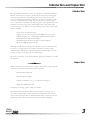
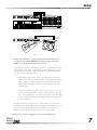
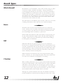
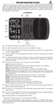
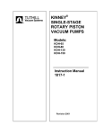
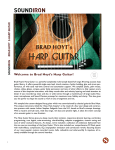
1
Stereo
Reverb
290
RO
OM
HA
LL
CH
AM
BE
R
PL
AT
E
CA
TH
ED
RA
L
GA
TY
PE
TE
D
SM
AL
L
ME
DI
UM
LA
RG
E
SIZ
E/
DA
RK
GA
TE
SH
AP
E
ME
D
BR
IG
HT
CO
LO
R
Operation
Manual
sh
ort
DE
0
CA
l
Y ong
-6
LE
FT
-12
-18
RI
GH
T
dry
MI
X
we
t
IN
PU
T
OU
¨
dbx Professional Products
8760 South Sandy Parkway
Sandy, Utah 84070 USA
Tel: (801) 566-8800
Fax: (801) 566-7005
dbx International Sales
3 Overlook Drive Unit 4
Amherst, New Hampshire
03031 USA
Tel: (603) 672-4244
Fax: (603) 672-4246
Table of Contents
Safety and Warranty . . . . . . . . . . . . . . . . . . . . . . . . . . . . . . . . . . 2
Introduction and Inspection . . . . . . . . . . . . . . . . . . . . . . . . . . . . 3
Setup
Front Panel . . . . . . . . . . . . . . . . . . . . . . . . . . . . . . . . . . . . 4
Back Panel . . . . . . . . . . . . . . . . . . . . . . . . . . . . . . . . . . . . 5
Connections . . . . . . . . . . . . . . . . . . . . . . . . . . . . . . . . . . . 6
Operation
Selecting Reverbs . . . . . . . . . . . . . . . . . . . . . . . . . . . . . . . . 8
Bypass Mode . . . . . . . . . . . . . . . . . . . . . . . . . . . . . . . . . . 9
Noise Gate . . . . . . . . . . . . . . . . . . . . . . . . . . . . . . . . . . . . 9
MIDI . . . . . . . . . . . . . . . . . . . . . . . . . . . . . . . . . . . . . . . 10
Reverb Types
What is Reverb? . . . . . . . . . . . . . . . . . . . . . . . . . . . . . . . . 12
Room . . . . . . . . . . . . . . . . . . . . . . . . . . . . . . . . . . . . . . . 12
Hall . . . . . . . . . . . . . . . . . . . . . . . . . . . . . . . . . . . . . . . . 12
Chamber . . . . . . . . . . . . . . . . . . . . . . . . . . . . . . . . . . . . . 12
Plate . . . . . . . . . . . . . . . . . . . . . . . . . . . . . . . . . . . . . . . . 13
Cathedral . . . . . . . . . . . . . . . . . . . . . . . . . . . . . . . . . . . . 13
Gated . . . . . . . . . . . . . . . . . . . . . . . . . . . . . . . . . . . . . . . 13
Specifications . . . . . . . . . . . . . . . . . . . . . . . . . . . . . . . . . . . . . . 14
Stereo
Reverb
290
1
Safety and Warranty
Safety
The symbols shown at left are
internationally accepted symbols
RISK OF ELECTRIC SHOCK
that warn of potential hazards
DO NOT OPEN
A T T E N T I O N : RISQUE DE CHOC ELECTRIQUE - NE PAS OUVRIR
with electrical products. The
W A R N I N G : TO REDUCE THE RISK OF FIRE OR ELECTRIC
lightning flash with arrowpoint in
SHOCK DO NOT EXPOSE THIS EQUIPMENT TO RAIN OR MOISTURE
an equilateral triangle means that
there are dangerous voltages present within the unit. The exclamation
point in an equilateral triangle indicates that it is necessary for the user
to refer to the owner's manual.
CAUTION
These symbols warn that there are no user serviceable parts inside
the unit. Do not open the unit. Do not attempt to service the unit
yourself. Refer all servicing to qualified personnel. Opening the
chassis for any reason will void the manufacturer's warranty. Do
not get the 290 wet. If liquid is spilled on the unit, unplug it
immediately and take it to a dealer for service. Disconnect the
equipment during storms to prevent damage.
Warranty
1. The warranty registration card must be mailed within 30 days after
purchase date to validate this warranty and proof-of-purchase is considered to be the burden of the consumer.
2. dbx warrants this product, when bought and used solely within the
U.S., to be free from defects in materials and workmanship under normal use and service.
3. dbx liability under this warranty is limited to repairing or replacing
defective materials that show evidence of defect, provided the product
is returned to dbx WITH RETURN AUTHORIZATION from the factory,
where all parts and labor will be covered up to a period of two years.
A Return Authorization number may be obtained from dbx by telephone. The company shall not be liable for any consequential damage
as a result of the product's use in any circuit or assembly.
4. dbx reserves the right to make changes in design or make additions to
or improvements upon this product without incurring any obligation to
install the same on products previously manufactured.
5. The foregoing is in lieu of all other warranties, expressed or implied,
and dbx neither assumes nor authorizes any person to assume for it
any obligation or liability in connection with the sale of this product.
In no event shall dbx or its dealers be liable for special or consequential damages or from any delay in the performance of this warranty
due to causes beyond their control.
2
Introduction and Inspection
Introduction
We congratulate and thank you for your purchase of the dbx 290 Stereo
Reverb. The 290 is a true stereo, dedicated reverb processor designed
for the professional who needs high quality results without the challenges of complex programming. Whether used in the recording studio
or in live sound situations, world class reverbs are just a button press
away. The 290 also includes unheard of signal to noise specifications for
products in its price range along with a digital noise gate that pushes
unwanted noise even further out of the audio picture. Some of the 290's
features include:
•
•
•
•
•
•
True stereo reverb processing
Signal to noise ratio of greater than 90dB (w/o noise gate)
40kHz sampling rate, 18 bit DACs, full bandwidth response
Balanced Stereo Inputs and Outputs
Hundreds of professional quality reverb possibilities
Receives MIDI program changes
Although the dbx 290 was designed to be the easiest reverb on the market to use, we suggest that you read this operation manual to fully
understand the 290's power. We have kept the manual simple and easy
to read so that you can get back to work quickly.
We know you'll enjoy your 290 and thanks again for purchasing a quality
dbx product.
Inspection
Before continuing any further, please inspect the contents of the dbx 290
box to be sure that the following items are included:
• dbx 290 Stereo Reverb
• External power supply
• Operation Manual (yes, you are already reading it)
• Registration/Warranty card
If anything is missing, please notify your dealer.
The information contained in this manual is subject to change at any
time without notification. Some information contained in this manual
may also be inaccurate due to undocumented changes in the product or
operating system since this version of the manual was completed.
Stereo
Reverb
290
3
Setup
Front Panel
ROOM
HALL
CHAMBER
PLATE
CATHEDRAL
GATED
SMALL
MEDIUM
LARGE
DARK
MED
BRIGHT
0
Stereo
Reverb
-6
290
-12
-18
short
TYPE
SIZE / GATE SHAPE
COLOR
1
2
3
dry
long
wet
DECAY
LEFT RIGHT
MIX
INPUT
OUTPUT
4
5
6
7
8
1) Type Buttons - Used to select one of six different reverb Types. The
LED inside the selected button lights to indicate the current reverb
Type being used.
2) Size/Gate Shape Buttons - Used to select one of three different
reverb Sizes or Gated Shapes if the Gated reverb Type is selected.
The LED inside the selected button lights to indicate the current
reverb Size or Shape being used.
3) Color Buttons - Used to select one of three different reverb Colors.
The LED inside the selected button lights to indicate the current
reverb Color being used.
4) Decay Control - Sets the length of the reverb's decay. Turning this
control clockwise increases the decay time while turning the control
counter-clockwise decreases the decay time. There are 12 different
times available (times are dependent on reverb Type and Size currently selected).
5) Input Level Meters - These LEDs monitor the levels of the incoming
signals which can be adjusted using the Input control.
6) Mix Control - Controls the wet/dry signal ratio. Turning the control
clockwise increases the amount of reverb sent to the outputs while
decreasing the original dry signal heard. Turning the control counterclockwise decreases the amount of reverb sent to the outputs while
increasing the original dry signal heard.
7) Input Level Control - Adjusts the level of the sound source being
fed into the 290's stereo inputs. For best signal performance, set
these controls so that -0- LED on the input meter lights occasionally.
If this control is set too high, unwanted distortion may be heard in the
output signals.
8) Output Level Control - Sets the stereo output level of the 290. This
control can be placed in a mirror setting for near unity signal gain
through the processor (e.g. Input Level control set at a 2 o'clock position and the Output Level control set at a 10 o'clock position).
4
Setup
Back Panel
INPUT
LEFT/MONO
OUTPUT
RIGHT
LEFT/MONO
FOOTSWITCH
MIDI IN
RIGHT
WARNING
¨
PROFESSIONAL PRODUCTS
A HARMAN INTERNATIONAL COMPANY
SALT LAKE CITY, UTAH
MADE IN USA
MODEL 290
STEREO REVERB
1
2
3
4
5
6
READ INSTRUCTIONS
BEFORE INSTALLATION
POWER
9VAC
USE ONLY
SPECIFIED
POWER
SUPPLY
SERIAL 290-xxxxxx
7
8
1) Left/Mono Input - This is the audio input for the left channel of the
290. It can be used in either balanced (TRS) or unbalanced (TS)
applications. For mono input configurations, use the Left Input jack
only and leave the Right Input jack disconnected.
2) Right Input - This is the audio input for the right channel of the 290.
It can be used in either balanced (TRS) or unbalanced (TS) applications. For mono input configurations, the Right Input jack must be
disconnected.
3) Left/Mono Output - This is the audio output for the left channel of
the 290. It can be used in either balanced (TRS) or unbalanced (TS)
applications. For mono output configurations, use the Left Output
jack only and leave the Right Output jack disconnected.
4) Right Output Jack - This is the audio output for the right channel of
the 290. It can be used for either balanced (TRS) or unbalanced (TS)
applications. The Right Output jack is used for both stereo in/stereo
out and mono in/stereo out configurations. For mono output configurations, the Right output jack must be disconnected.
5) Remote Footswitch - Allows the connection of an external momentary footswitch (Tip-Sleeve plug) for remotely placing the 290 into
bypass mode (indicated by flashing the selected Type/Size/Color
LEDs). A three switch type pedal (Tip-Ring-Sleeve plug) may also be
used to add Program up and Program down capabilities.
6) MIDI Input - The MIDI In port allows the 290 to respond to incoming MIDI program changes.
7) 290 Serial Number - This is the 290's unique registration serial number.
8) AC Power Adapter Input - This is where the AC power adapter is
connected. Warning: Use only the Power Adapter supplied with the
290 from the factory. Using any other Power Supply may permanently damage the 290.
Stereo
Reverb
290
5
Setup
Connections
Correctly connecting audio and power to any signal processor is the
most important step towards successful audio processing. Please follow
these steps carefully for best results:
1. Turn off all equipment before making any connections
2. Mount the 290 in a rack (optional)
The 290 requires only one standard rack space. It can be mounted
above or below anything that doesn't generate excessive heat, since it
requires no special ventilation. Ambient temperatures should not
exceed 113˚F (45˚C) when equipment is powered.
3. Make audio connections via 1/4" phone jacks according to your
requirements.
Although the 290 is a true stereo reverb processor, it can also be used
in a mono in/stereo out or mono in/mono out configuration. The
290 configures itself by sensing whether or not plugs are inserted into
the Right Input and Right Output jacks.
For mono input applications, use the Left Input jack only. For stereo
input applications, use both Left and Right Input jacks.
Likewise, for mono output applications, use the Left Output jack only.
For stereo output applications, use both Left and Right Output jacks.
Typically, the 290's inputs are connected to the auxiliary sends (sometimes called effect sends) of a mixing console. The 290's outputs are
then connected to the effect returns on the console. For best results,
a stereo effect return should be used. See figure 1-1.
L/R Outputs
ROOM
HALL
CHAMBER
PLATE
CATHEDRAL
GATED
SMALL
MEDIUM
LARGE
DARK
MED
L/R Inputs
Aux Sends 1/2
Stereo
FX Return
BRIGHT
0
Stereo
Reverb
-6
290
-12
-18
short
SIZE / GATE SHAPE
dry
long
DECAY
TYPE
LEFT RIGHT
wet
MIX
INPUT
OUTPUT
COLOR
Figure 1-1
The 290 can also be used in a keyboard setup as in figure 1-2 or in a
guitar rig as in figure 1-3.
6
Setup
L/R Outputs
ROOM
HALL
CHAMBER
PLATE
CATHEDRAL
GATED
SMALL
MEDIUM
LARGE
DARK
MED
L/R Ins
Channel Inputs
BRIGHT
0
Stereo
Reverb
-6
290
-12
-18
short
dry
long
DECAY
TYPE
LEFT RIGHT
wet
MIX
INPUT
OUTPUT
COLOR
SIZE / GATE SHAPE
Synth Outs L/R
Figure 1-2
L/R Outputs
ROOM
HALL
CHAMBER
PLATE
CATHEDRAL
GATED
SMALL
MEDIUM
LARGE
DARK
MED
Left Input
BRIGHT
0
Stereo
Reverb
-6
-18
short
SIZE / GATE SHAPE
dry
long
DECAY
TYPE
LEFT RIGHT
Effect Loop Send
Effect Loop
Stereo Return
290
-12
wet
MIX
INPUT
OUTPUT
COLOR
Figure 1-3
4. Connect the AC power supply (shipped with the unit) to the
rear panel jack labeled POWER and then plug the AC power
supply to an appropriate AC power source.
The 290, like any piece of computer hardware, is sensitive to voltage
drops, spikes, and surges. Interference such as lightning or power
"brownouts" can seriously, and in extreme cases, permanently damage the circuitry inside the unit.
• Spike/Surge Suppressors - This is an inexpensive solution to
all but the severest of AC line dangers. Surge protected power
strips usually cost only slightly more than unprotected strips,
making them a worthy investment for protection of all your
valuable gear.
• AC Line Conditioners - This is the best way to go for total protection from improper line voltages, albeit the more expensive
way. Line conditioners constantly monitor for excessively high
or low voltages and adjust accordingly, thus delivering consistent power levels.
To help keep things quiet, be sure to keep audio lines as far away
from power lines as possible. If it is necessary to cross audio and AC
lines, cross them perpendicular to one another. As a rule, never
allow parallel audio and AC lines to lie close to each other.
5. Power may now be re-applied to your other equipment.
Stereo
Reverb
290
7
Operation
Selecting Reverbs
The 290 has been designed to make reverb selection as quick and easy
as possible. Reverbs are divided into four parts:
• Type - Six standard reverbs are available in the 290: Room, Hall,
Chamber, Plate, Cathedral, and Gated. These are described further
in the Reverb Types Section (page 12).
• Size/Shape - There are three possibilities available: Small, Medium,
and Large. This parameter changes the overall size or volume
(width x length x height) of the room. It also affects the reverb
decay setting since smaller enviroments produce shorter decay
times. Larger spaces typically produce longer decays.
If the Gated Reverb is selected, these buttons choose one of three
different Linear reverb Types:
1)
- Reverse linear reverb. Gives the illusion that the signal
is being played in reverse since the reverb energy builds up
instead of decays.
1)
- Gated linear reverb. Emulates the sound of a high
energy reverb being cut off by a gate before it has a chance to
decay completely.
1)
- Normal linear reverb. Contains lots of energy but
decays quickly, making it ideal for small live room emulation.
• Reverb Color - There are three ambience colors to choose from:
Dark, Medium and Bright. This control does more than just make
simple equalization changes to the reverb; it also changes room
damping and high frequency reverb decay roll-offs. Each reverb
Type uses its own set of colorations, while the Medium setting is
usually considered the least colored.
• Reverb Decay - Sets the decay time of the reverb and is dependent
on the the reverb Size selection. Let your ears be the judge as to
how much reverb decay you need for your application.
Simply press the buttons associated with the desired reverb Type,
Color/Shape and Size. The reverb decay Time can be adjusted using the
Decay control at any time. The 290 also remembers the last used settings even after the unit is powered down.
8
Operation
Bypass Mode
To place the 290's reverb into Bypass mode, press and hold the [ROOM]
and [CHAMBER] reverb Type buttons simultaneously. Bypass mode is
indicated by the flashing LEDs of the currently selected Type/Size/Color
buttons. Pressing any button will exit the Bypass mode (along with
changing the setting if a new Type/Size/Color is selected). An external
footswitch can also be used to enter or exit the Bypass mode.
NOTE: Bypass mode affects only the wet portion of the Wet/Dry signal
(this means that Bypass acts as a reverb mute).
Noise Gate
The dbx 290 includes a digital noise gate to push the noise floor down,
ensuring that the 290 is at its quietest when sitting idle (the most important time to be quiet). The noise gate is located just before the 290's
reverb, which the means reverb's decay never gets prematurely cut off.
Threshold is the one parameter that may need adjustment in your particular application. This is the level at which the gate will open. Threshold
ROOM
HALL
CHAMBER
PLATE
CATHEDRAL
GATED
SMALL
TYPE
MEDIUM
LARGE
SIZE / GATE SHAPE
Level 3 (highest threshold)
Level 2
Level 1
Level 0 (off)
is set by doing the following:
• Simultaneously press and hold the [SMALL] and [LARGE] Size buttons until their respective LEDs light.
• The current threshold setting is displayed using the reverb Type
LEDs in the following manner:
• To choose a new Threshold setting, simply select one of the first
four Type buttons for the desired level.
The 290 pauses briefly to show your selection and then returns to
normal operation mode.
The purpose of the noise gate is to eliminate unwanted noise in the
absence of program material at the 290's inputs. This unwanted noise
usually comes from other not-so-quiet pieces of equipment. By using
Stereo
Reverb
290
9
Operation
the gate, the noise can be eliminated when it is most offensive (when
there is no program material to cover up the problem).
The noise gate can be disabled by choosing level 0 (off).
MIDI
MIDI program changes can be received on any MIDI channel to select
different reverb settings on the 290. The 290's MIDI channel is set by
doing the following:
• Simultaneously press and hold the [DARK] and [BRIGHT] Color buttons until their respective LEDs light.
• The current MIDI channel setting is displayed using the reverb
Type and Size LEDs in the following manner:
ROOM
HALL
CHAMBER
PLATE
CATHEDRAL
GATED
Ch 1
Ch 2
Ch 3
Ch 4
Ch 5
Ch 6
Ch 7
Ch 8
Ch 9
Ch 10
Ch 11
Ch 12
Ch 13
Ch 14
Ch 15
Ch 16
Omni
Off
SMALL
TYPE
MEDIUM
LARGE
SIZE / GATE SHAPE
DARK
MED
BRIGHT
COLOR
To change the currently selected MIDI channel:
• Select one of the three Size buttons.
• Select one of the six Type buttons for the new desired channel.
The 290 pauses briefly to show your selection and then returns to
normal operation mode.
Once the MIDI channel is correctly set, the 290 will respond to
Continuous Controller and Program Change commands. To allow different reverb decay times using MIDI, the 290 responds to MIDI Continuous
Controller #1 on the selected MIDI channel. The 290 has 12 different
decay times (actual decay times depend on the reverb Type and Size
selected) that can be selected using these specific Continuous Controller
values:
CC1 Value
0-9
10-19
20-29
30-39
~ 111-119
120-127
10
Selection
Use current reverb Decay control position
Select knob position 1
Select knob position 2
Select knob position 3, etc...
Select knob position 11
Select knob position 12
Operation
The list below shows how different reverb settings can be recalled using
Program Changes. Program Change command -0- toggles the 290's
Bypass mode status. Program changes -1- to -54- can also be used to exit
the Bypass mode and select a new reverb setting (if so desired). After
responding to a valid Program Change request, the 290 will reset the
decay time to the 12 o'clock position (decay setting number 5) regardless
of where the reverb decay control is set. Any Program Change higher
than -54- will be ignored by the 290.
Prg #
0
1
2
3
4
5
6
7
8
9
10
11
12
13
14
15
16
17
18
19
20
21
22
23
24
25
26
27
Type
Bypass
Room
Room
Room
Room
Room
Room
Room
Room
Room
Hall
Hall
Hall
Hall
Hall
Hall
Hall
Hall
Hall
Chmbr
Chmbr
Chmbr
Chmbr
Chmbr
Chmbr
Chmbr
Chmbr
Chmbr
Size
(Toggle
Small
Small
Small
Med
Med
Med
Large
Large
Large
Small
Small
Small
Med
Med
Med
Large
Large
Large
Small
Small
Small
Med
Med
Med
Large
Large
Large
Color
On/Off)
Dark
Med
Bright
Dark
Med
Bright
Dark
Med
Bright
Dark
Med
Bright
Dark
Med
Bright
Dark
Med
Bright
Dark
Med
Bright
Dark
Med
Bright
Dark
Med
Bright
Prg #
Type
Size
Color
28
29
30
31
32
33
34
35
36
37
38
39
40
41
42
43
44
45
46
47
48
49
50
51
52
53
54
Plate
Plate
Plate
Plate
Plate
Plate
Plate
Plate
Plate
Cathdrl
Cathdrl
Cathdrl
Cathdrl
Cathdrl
Cathdrl
Cathdrl
Cathdrl
Cathdrl
Gated
Gated
Gated
Gated
Gated
Gated
Gated
Gated
Gated
Small
Small
Small
Med
Med
Med
Large
Large
Large
Small
Small
Small
Med
Med
Med
Large
Large
Large
Rise
Rise
Rise
Flat
Flat
Flat
Decay
Decay
Decay
Dark
Med
Bright
Dark
Med
Bright
Dark
Med
Bright
Dark
Med
Bright
Dark
Med
Bright
Dark
Med
Bright
Dark
Med
Bright
Dark
Med
Bright
Dark
Med
Bright
Note: Program changes 1 through 54 will also exit Bypass mode.
Stereo
Reverb
290
11
Reverb Types
What is Reverb?
Reverberation, or room ambience, occurs when acoustic energy is reflected off room surfaces, materials and objects. Using reverberation in
recorded program material gives the listener a sense that the material is
being performed in an actual room or hall. It is this similarity to actual
acoustic spaces that makes reverberation a useful tool in recorded music.
The 290 also uses early reflections to get a better emulation of the natural sound of a room. Early reflections are short clusters of direct reflections from the closest walls in the room.
The 290 includes several different types of reverb. Some are very natural
sounding environments, while others are not-so-natural sounding.
Room
The Room is the most basic environment because we actually hear
rooms. Usually rooms are smaller environments and because their walls
are closer together, early reflections are heard more prominently while
the overall length of the reverb decay is quite short.
Natural small room ambiences will work wonders in trying to bring sterile, dry musical instrument samples back to life (like drum samples for
example). Small rooms also help thicken up sounds without adding a
lot of long decay reverberations.
Hall
Halls almost fall into the special category of unnatural ambiences
because they are designed and treated with certain sound reflection characteristics. Performance halls are built with the goal of getting the sound
off the performance stage as cleanly and loudly as possible. Early reflections are practically non-existent while the reverb decay of the environment is extremely smooth and transparent.
Halls are ideal for the instruments they were designed for like strings,
pianos, orchestras, etc. The transparent quality of the decay makes halls
one of the most commonly used ambiences in recording.
Chamber
Many recording studios have tried to emulate hall environments by building special sound chambers. These small rooms have unique wall angles
and surfaces. Sound is fed into the room through a speaker and the
reflections are retrieved with one or more microphones. Early reflections
in these rooms are quite strong and even but because the room is small,
the reverberation decays more quickly than in a real hall.
Although not a perfect emulation of the hall, the chamber has become a
preferred ambience for multi-tracked recordings that need reverb. Since
12
Reverb Types
the chamber's decay tends to get out of the way more quickly than the
hall's, the chamber is ideal for vocals and/or instrumental parts that tend
to get stacked during recording. Chambers are also very useful for more
percussive, upbeat styles of music.
Plate
Plates are another attempt to artificially emulate natural ambiences that
have instead become accepted for their own unique sound. Plate
reverbs are made with large sheet of metal suspended in a box. Sound
is induced at one end of the metal sheet with transducers that cause the
metal to vibrate. Pickups at the other end of the metal receive the multiple reverberations.
The results are quite unique. The Plate reverb has a slight metallic quality that makes instruments and voices sound a little brighter and thus
more present. Reverb plates have a very thin, smooth high end while
the low end is more dense. These characteristics work well for percussion instruments.
Cathedral
The most natural and familiar environment is probably that of the cathedral or church. Often large churches are built for the purpose of housing visual ornamentation and seating large groups of people for worship.
By the sheer size of these rooms and the amount of people in them (or
sometimes how empty they were), cathedrals and churches all over the
world have become famous for their unique sound qualities.
These large rooms usually have a great deal of early reflection energy
(because of smaller pulpit areas) while the reverb itself is very rich in the
lower frequencies (because of the large room's ability to sustain low frequency energy). The cathedral reverbs make anything sound big,
whether it's an organ with a choir or a thunder clap.
Gated
Linear reverberation, or gated reverbs as they are more commonly refered to, are the most unnatural ambiences used on a regular basis.
Originally, large dense reverbs were cut off using a noise gate.
Eventually, it was discovered that using very linear reverbs with no
regeneration produce the same type of sound with even more flexibility.
Since the decay is linear, the shape of the reverb can be changed. Using
the flat setting gives you the familiar gated reverb sound. The reverse
setting ramps the energy from its lowest point up, making things sound
almost backwards. The normal ramp down setting can be used as standalone early reflections to emulate very small, intense rooms.
Stereo
Reverb
290
13
Specifications
dbx 290 Stereo Reverb
A/D Converter: 16 bit PCM
D/A Converter: 18 bit PCM
Sampling Frequency: 40 kHz
DSP Section:
Architecture: ..........................Static-Dynamic Instruction Set Computer
(S-DISC™)
Digital Signal Path Width: ....24 bits (144.5 dB)
Internal Data Path Width: ....48 bits (289 dB)
Dynamic Delay Memory: .....64k x 20 bits (1.68 seconds)
Static Delay Memory: ...........256 24-bit registers (6.55 milliseconds)
Data ALU Processing: ............10.0 MIPS
Address ALU Processing:.......15.0 MIPS
Multiplier Size: .......................24 bits x 24 bits
Input Section:
Connector: 1/4” Balanced TRS
Nominal Level: +4 dBu
Maximum Level: +18 dBu
Impedance: 20 kohms
Output Section:
Connector: 1/4” TRS
Nominal Level: +4 dBu
Maximum Level: +18 dBu
Impedance: 470 ohms
General:
Frequency Response: 20 Hz. - 20 kHz. +0, -3 dB
S/N ratio: Greater than 87 dB; ref = max signal, 22 kHz measurement
bandwidth
Total Harmonic Distortion: Less than 0.02% (1 kHz.)
Power Requirements:
US and Canada:... ...........120 V ac, 60 Hz
Japan:...............................100 V ac, 50/60 Hz
Europe:.... ........................230 V ac, 50 Hz
UK:...................................240 V ac, 50 Hz
For other countries, check with local distributors
Power Consumption: .............15 watts
Dimensions: ..........................19” W x 1.75” H x 4.25” D
(482mm x 44mm x 107mm)
14
Specifications
Function...
Basic
Channel
Default
Channel
Mode
Default
Messages
Altered
Note
Number
Velocity
After
Touch
Pitch Bender
True Voice
Note ON
Note OFF
Key's
Ch's
Transmitted
Recognized
1-16
1-16
1-16
1-16
Mode 3
X
X
Mode 3
X
X
X
X
X
X
X
X
X
X
X
X
X
X
O
O
0-127
0-54
0-54
X
X
X
X
X
X
X
X
X
X
X
X
X
X
X
X
X
X
X
X
Control
Change
Prog
Change
True #
System Exclusive
:Song Pos
:Song Sel
:Tune
Common
System
:Clock
Real Time :Commands
:Local ON/OFF
Aux
:All Notes Off
Mes:Active Sense
sages
:Reset
System
Remarks
Memorized
Same as Basic Channel
CC#1 only
Notes
Mode 1 : OMNI ON, POLY
Mode 3 : OMNI OFF, POLY
Stereo
Reverb
290
Mode 2 : OMNI ON, MONO
Mode 4 : OMNI OFF, MONO
O : Yes
X : No
15
Manual Version: 2.04
Part Number: 18-1630-B