1
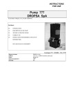
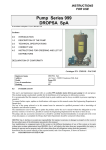
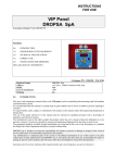
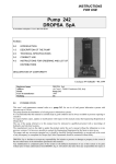
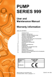
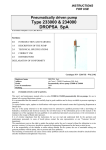
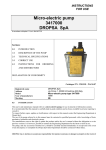
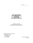
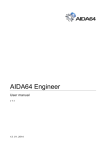
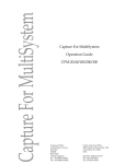
INSTRUCTIONS
FOR USE
Pump 777
DROPSA SpA
In accordance with para. 1.7.4, of I, Dir CEE 89/392
Sections:
0.0
INTRODUCTION
1.0
DESCRIPTION OF THE PUMP
2.0
TECHNICAL SPECIFICATIONS
3.0
CORRECT USE
4.0
INSTRUCTIONS FOR ORDERING AND LIST OF
DISTRIBUTORS.
DECLARATION OF CONFORMITY
Catalogue P/N C2018IE - Wk 17/99
Registered name
Address
Model
Year of manufacture
Marking
DROPSA SpA
via Croce 1, 20090 Vimodrone (MI), Italy
Pump 777
1999
CE
0.0
INTRODUCTION
This user’s and maintenance manual refers to pump 777, for use in lubrication systems for oil and grease, including
high pressure systems (up to 500 bar).
The use of this pump permits the distribution of oil and grease in lubrication systems at pressures up to 500 bar.
It is recommended that this manual is carefully kept in good condition and is always available to persons requiring to
consult it.
To request further copies, updates or clarifications with respect to this manual contact the Engineering Department at
Dropsa SpA.
The use of the pump referred to in this manual must be entrusted to qualified personnel with a knowledge of
hydraulics and electrical systems.
The manufacturer reserves the right to update the product and/or the user’s manual without the obligation to revise
previous versions. It is however, possible to contact the Engineering Department for the latest revision in use.
The pump, and any accessories mounted on it, should be carefully checked immediately on receipt and in the event
of any discrepancy or complaint the Dropsa SpA Sales department should be contacted without delay.
DROPSA S.p.A. declines to accept any responsibility for injuries to persons or damage to property in the event of
the non-observance of the information presented in this manual.
Any modification to component parts of the system or the different destination of use of this system or its parts
without prior written authorisation from DROPSA S.p.A. will absolve the latter from any responsibility for injury or
damage to persons and/or property and will release them from all obligations arising from the guarantee.
Instructions for the correct ordering of the required model, and a list of importers, is shown in Section 4.
1.0
DESCRIPTION OF THE PUMP
The 777 series lubrication pumps can be adapted to meet many requirements without mechanical modifications, even
where the pump is already installed. By choosing from among a range of perfectly compatible and easily assembled
components, variations can be made to the pressure, the quantities of lubricant delivered, the type of lubricant or the
type of distribution.
This construction technique is based essentially on the following modules:
• Motor and reduction unit
• Dual element pump
• Tank
• Valves and output assembly (reverser, etc.)
The supporting structure is common to all versions, with the dual pumping element constituting the essential module.
From one pump assembly there are provided two separate outlets for the lubricant, protected by double non-return
valves. The two ways can be connected together to double the quantity of lubricant on one line only or they can be
employed separately on two independently controlled single line circuits.
On the same support structure it is possible to mount types of tank with different volumes suitable for oil or grease
with paddle units and level indicators.
The control of the motor is obtained by use of normal electrical equipment which provides for the reversing of the
direction of rotation and the execution of the programmed cycles.
The motor-driven pump 777 is totally protected from the external environment and can operate without difficulties
in the severest environmental conditions.
The pump is composed of a series of components with the following characteristics:
CHARACTERISTICS
PUMP 777
Pump capacity
cc/min
Maximum pressure in bars
Tank capacity in litres
max. 130
C2018IE - Pump 777 - Rev. 0
500 (7350 psi)
10 - 30 - 100
Jan. 1999
Page 2
By-pass rating
(with internal regulating screw)
Minimum operating time
(sec)
Mineral lubricant characteristics at
working temperature
Working temperature
Motor
Absorbed
Power
Grade of protection
Insulation
300 bar (4410 psi)
24
(minimum pause time 96 sec)
CSt 15 - 1500 (oil)
max NLGI 2 (grease)
- 5 °C ÷ + 40 °C (+23°F ÷ +104°F)
Three phase 220 – 380 V
50 Hz – 4 pole
1500 rpm
370 W
On request 750 W
IP55
Class F
It is also possible to supply the pump with a mechanical or hydraulic reverser.
1.1
Pump assembly (Code 291415)
The assembly is made up of two identical pump units, each one having two identically sized pistons. The pistons are
in ground and lapped hardened steel; one of these acts as the pump and the other as the control valve. The pump
housing is in steel; the ports are bored and lapped; the drive shaft is in hardened and ground steel.
1.2
Reduction unit
The reduction unit casing is in aluminium. The drive shaft with worm screw is hardened and ground. The worm
wheel is in hardened steel.
Both the drive shaft and the worm wheel shaft are fitted with ball bearings.
The free wheels used on this pump are among the best brands on the market.
Attention: lubrication of the reduction unit in dual line grease systems is ensured by the return of grease into the
pump via port (F). Where the pump is utilised for grease on a single line system (where there is no return to the
pump) it would be advisable to provide a point for lubrication of the reduction unit through port (F).
Obviously, in an oil system this precaution is not necessary as all parts of the reduction gears are effectively in an oil
bath.
1.3
Reverser
1.3.1
Electro-mechanical reverser
When the pump is installed in a dual line system it is necessary to utilise this reverser.
The mounting is already prepared with fixing holes to accept this device, whose functioning is tied to the
use of the reverser and lubrication cycle electrical control equipment.
The main parts of the device are:
• the reverser in steel with a hardened, ground and lapped piston;
• cam assembly and freewheel in hardened steel;
• two watertight micro-switches which control the reversing and the exact positioning of the piston.
The front of the reverser is prepared with a hole for connecting a manometer.
OPERATION AND ADJUSTMENT OF THE CONTACTS
One of the original features of this motor-driven pump is that of utilising the motor both for the movement
of the pistons of the pump unit and for the reversing of the line.
The motor, after the required pause between one lubrication and the next, is started by turning the worm
screw, the worm wheel and the pump assembly.
The worm wheel has an external appendix on which is mounted a cam for the reversing of the line.
When the motor drives the pump, the worm wheel shaft rotates anticlockwise for as long as the cam, for
C2018IE - Pump 777 - Rev. 0
Jan. 1999
Page 3
the effect of the free wheel, remains stationary.
The pump feeds line 1 and, after having filled the tubing and the valves, will act on the contact of the end
of line pressure switch which, through the electrical equipment, provokes the inversion of the motor
direction. This reversing will result in the reversing of the rotation of the cam shaft, while the pump will
stop instantaneously; also the pump drive shaft is attached with the free wheel.
The line reversing cam will rotate rapidly to the closure of the microswitch (32) contact, the motor will
reverse direction returning to drive the pump to feed line 2.
The closing of the line 2 pressure switch contact will provoke a further inversion of the initial rotation by
actuating the second microswitch closing contact. (32).
The closing of this contact will reverse the rotation of the motor for a period of approx. one second; this
will conclude the lubrication cycle.
1.3.2
Hydraulic reverser
The lubricant which comes from the pump through the central part of piston A (Fig.1) is distributed into
chamber C, entering into line 1 and tending to position piston B toward the left.
When the set pressure of spring M1 is reached, the small piston S1 of the sequence valve lifts and permits
the lubricant to enter into chamber D.
Piston A is moved toward the left; lubricant is sent into chamber E, the small piston B is moved to the
right (Fig.2) and the lubricant enters into line 2 while line 1 discharges (return).
When the set pressure of spring M2 is reached, lubricant is sent into chambers C and F; pistons A and B
invert their positions and the delivery is again directed to line 1.
The necessary reversing pressures are attained by regulating the loading of springs M1 – M2.
1.4
Pressure Control Valve
Code
291162
Pressure 50 ÷ 500 bar (735 ÷ 7350 psi)
Description
291391
Pressure 20 ÷ 250 bar (294 ÷ 3675 psi)
Also these valves can be easily disassembled for inspections.
They are adjustable and have the function of regulating the pressure.
It is important to keep in mind that the inversion of the lines is controlled by the closing of the pressure switch
contacts.
The regulation of the pressure switch must involve an operating pressure which is always less than the maximum
pressure controlled by this valve.
1.5
Flow regulator (Code 3293060)
The flow regulator serves to regulate the quantity of lubricant delivered at each pump cycle.
It can easily be set between * 14.5 - 65 cc./1 by turning the rear nuts code 3235097 clockwise or anticlockwise.
It is also applicable to a single pump element.
C2018IE - Pump 777 - Rev. 0
Jan. 1999
Page 4
1.6
Minimum and maximum level indicators
1.6.1
Indicator for grease
Minimum level
Code
291244
For 10 kg tank. (22 lb)
Description
291220
For 30 kg tank. (66.1 lb)
291210
For 100 kg tank. (220.4 lb)
This device is used when it is wished to control the minimum level of the tank where the use of a paddle
unit is provided for grease.
The operation of the minimum level contact occurs through the reaction of the blade with the shaft (7)
opposing the grease moved by the arm of the moving paddle.
The minimum level contact serves to illuminate the warning lamp on the electrical panel and additionally
for any command signal to an automatic tank refilling pump.
Maximum level
This indicator must always be provided when it is wished to incorporate automatic tank refilling.
The refilling pump is automatically set in operation when the grease in the tank falls below the minimum
level actuating the respective electrical contact.
To avoid the refilling pump continuing to deliver lubricant beyond the capacity limit of the tank it is
essential to incorporate a maximum level microswitch with which to stop the pump.
1.6.2
Minimum and maximum level indicators for oil
Code
Description
291155
Maximum level indicator
291275
Minimum level indicator for 30 l tanks.
291276
Minimum level indicator for 10 l tanks.
291291
Minimum level indicator for 100 l tanks.
Two magnetic contact indicators are incorporated for the control of the minimum and maximum oil levels.
The cover is suitably prepared for receiving these devices; the output cables can be run through a single
sheathing for connecting to the electrical control equipment.
1.7
Paddle unit for grease
Tanks are provided in three different capacities: 10, 30 and 100 kg. (22, 66.1 , 220.4 lb).
There is a “paddle unit for grease” assembly for each capacity.
The pump mounting, which also supports the tank, is prepared for receiving this assembly.
To install the paddle unit when the pump is already mounted, it is sufficient to remove the tank.
In addition to the perforated disk, which supports the paddle unit assembly, there is also provided, on the upper part,
a steel mesh filter disk with 0.5 mm holes. In this way the pump is protected from any foreign bodies that could be
encountered even in grease from sealed drums or which may inadvertently fall into the tank during refilling from
above.
Where the blade is not able to push very thick (above grade 3) grease through the holes in the filter mesh, or when
working at very low temperatures, the filter disk can be removed. However, care must then be taken to ensure that
refilling is carried out using a suitable manual or pneumatic pump and a filter, code 3130009.
Refilling of the tank by hand is not recommended.
C2018IE - Pump 777 - Rev. 0
Jan. 1999
Page 5
1.8
Manometer
Code
20550
1000 bar (14700 psi)
1.9
Description
Only one version is provided
Operating control
The pump 777 can be supplied with an electrical control panel with indicators for on/off, minimum and maximum
lubricant levels, pressurisation of the two lines, alarms, lubrication cycle not respected and power on.
In addition there is a selector for continuous operation or timed by the system, and two timers for regulating the
pause and lubrication times.
1.10
Electrical equipment
“DROPSA” electrical equipment has been designed with the aim of supplying a system complete with all the
controls necessary for automatic operation and controlled by centralised lubrication system safety signalling.
1.10.1
Equipment for dual line systems
This equipment is enclosed in a robust metal cabinet with IP 55 grade protection, and is available in
different versions for the command and control of the 777 Series pumps with electromechanical or
hydraulic reversers.
It is equipped with two yellow warning lamps (B and G) for signalling minimum and maximum lubricant
levels, two white lamps (C and D) which signal the pressurisation of respectively lines 1 and 2 and a red
alarm warning lamp (F) which illuminates when the lubrication cycle is not effected in the time set on the
cycle control timer.
A green lamp (A) indicates power on, while a blue lamp (E) indicates the functioning of the pump.
A reset button (H) resets the system after an alarm and a selector (I) permits the selecting of either
continuous operation or timed by the system.
Two multi-scale electromechanical timers facilitate the simple and rapid setting of the pause and lubrication
times (working time of the pump).
The minimum and maximum work and pause times and the variations depend on the type of scale set.
The pause timer is equipped with a mechanical lock device which, in the event of a power off during the
pause, locks the timer in the position reached.
Code
1641295
1638489
1638488
1638540
1.10.2
Description
For 777 pumps with electromechanical reverser
For 777 pumps with hydraulic reverser
As the 1638489 but c/w acoustic alarm signal
As the 1638489 but in a flameproof version
Equipment for progressive systems
This equipment is enclosed in a robust metal cabinet with IP 55 grade protection, and is equipped with an
electronic timer for the setting of the pause time and an electromechanical timer for setting the lubrication
time (working time).
The maximum standard pause time is 1 hour with variations of 2.5 min. By specifying when placing the
order or by acting on the electrical jumper situated in the timer it is possible to obtain a maximum pause
time of 8 hours (20 min. variations) or 24 hours (1 hour variations).
The working time can be regulated from 0 to 12 minutes with variations of 12 seconds.
It is equipped with alarm warning lights for lack of lubricant and minimum level in the tank.
A reset button resets the system after an alarm and a further button is used as a lubrication cycle manual
control.
C2018IE - Pump 777 - Rev. 0
Jan. 1999
Page 6
2.0
TECHNICAL CHARACTERISTICS
2.1
Fixing and overall dimensions
2.2
Electrical system – Technical Data
Electrical power supply:
Absorbed power:
C2018IE - Pump 777 - Rev. 0
380 - 220 V 50/60 Hz
Approx. 370 W
Jan. 1999
Page 7
2.3
Hydraulic system – Technical Data
Connections from the gear pump to the valve body by means of nylon tubing with external ∅ 4 mm (see attachment
7);
2.4
Other data
Class of protection
Grade of mechanical protection
Operating temperature
Operating humidity
Conservation temperature
Level of continuous sound pressure
3.0
CORRECT USE
3.1
Putting into service
F
IP55
-5 ÷ +40°C (+23°F ÷ +104°F)
90% relative humidity
-20 ÷ +50°C (-4°F ÷ +122°F)
< 70 dB(A)
Damage to the power supply cable and housing could result in contact with high voltage live parts and hence be a
danger to life:
♦ carefully check the integrity of the power supply cable and the unit before use;
♦ In the event of there being damage to the power supply cable or the unit, DO NOT put the system into service!;
♦ Replace the damaged power supply cable with a new one;
♦ The unit can be opened and repaired ONLY by qualified personnel;
♦ In order to prevent dangers of electric shock due to direct or indirect contact with live parts it is necessary that
the electrical power supply line is adequately protected by a suitable differential magnetothermal circuit breaker
with an intervention threshold of 0.03 Ampere and a max. operating time of 1 second.
The breaking capacity of the circuit breaker must be ≤ 10 kA and the nominal current In = 6 A.
♦ The submersed pump MUST NOT be utilised in fluids or environments which are particularly aggressive or
explosive/inflammable if not prepared for this purpose beforehand by the supplier.
♦ For correct fixing verify the distance between centres shown in the diagram in Section 2.
♦ Use gloves and safety glasses as required in the lubrication oil safety chart;
♦ DO NOT use aggressive lubricants with NBR gaskets and seals; if in doubt consult the Engineering Department
of Dropsa SpA, who will provide a chart with the details of recommended oils;
♦ DO NOT ignore dangers to health and observe all hygiene standards;
♦ WARNING! All electrical components must be grounded. This refers to both electrical components and control
devices. In this regard ensure that the ground cable is correctly connected. For reasons of safety the ground cable
must be approx. 100 mm longer than the phase cables. In the event of accidental detachment of the cable, the
ground terminal must be the last to be removed.
C2018IE - Pump 777 - Rev. 0
Jan. 1999
Page 8
action to be taken prior to start up
♦ Verify the integrity of the pump;
♦ Fill the tank with suitable lubricant;
♦ Verify that the pump is at operating temperature and the tubing free from air bubbles;
♦ Check that the electrical connections have been effected correctly (UNI 64/8, IEC …);
The pump is supplied with a maximum and minimum level switch
3.2
Use
1.
2.
3.
4.
3.3
verify the settings made;
press the start button of the machine to which the 777 pump is connected;
verify the starting up of the pump;
verify the adequate lubrication of the machine (if doubt exists as to the correct functioning consult the
Engineering Department of Dropsa SpA to request test procedures).
Transport and storage
Transport and storage is effected in a wooden package.
No particular precautions are required except as noted on the package itself.
Handling must be effected utilising suitable lifting devices.
!
After having removed the packaging, lift the pump utilising the appropriate brackets provided on the sides
of the base.
!
The machine components can withstand temperatures, during storage, from -20 to +50°C (-4°F ÷ +122°F);
however, in order to avoid damage, starting of the machine should occur at a minimum temperature of -5°C
(23°F).
3.4
Assembly/Disassembly
No pump assembly operations are envisaged.
For the fixing of the unit the holes provided in the inside of the base must be used. Adequate space is provided (as
shown in the installation diagram) to avoid abnormal postures and the possibility of impacts (see Section 2)
Subsequently it will be necessary, as previously described, to connect the pump to the machine hydraulically and
then to connect the control panel.
Remove the countersunk screws (9) and the locating pins (17) from both plates.
Remove the retaining rings (6 and 7) and the key (2).
Using screws in the M8 threaded holes, withdraw the plate (15) with the ball bearing (4) from the central shaft (11).
Remove the shim (12) and remove the lateral blocks (19) with the pistons (21).
Remove the springs and the cams withdrawing them from the shaft (11). Unhook the springs (18).
!
before withdrawing the pistons from the blocks (19) mark them (they must be reassembled in the same
seating).
Remove the washer (12) and the shaft (11), utilising a press or an extractor.
The bearings (4 and 5) must be removed with care from their seatings.
It is now possible to proceed with disassembling the parts of the pumping element blocks (22) after having
withdrawn the pistons, removing the dowel (1), the ball (8), the plug (10) and the taper plug (20).
!
the plugs (20) are slightly tapered; therefore it is advisable to replace them on reassembly.
During the disassembly the tank emptied.
Disconnect the electrical and hydraulic parts.
Where the machine is to be scrapped, do not dispose of potentially polluting parts in the environment, following
local regulations for their correct disposal.
At the time of the machine being scrapped it is necessary to remove and destroy the identification plate and all other
relative documents.
C2018IE - Pump 777 - Rev. 0
Jan. 1999
Page 9
3.5
Regulation
pressure
The working pressure can be regulated by rotating the by-pass screw clockwise to increase the pressure and
anticlockwise to decrease it. During this operation pay attention to the rotary joint.
Flow rate regulation
Serves to regulate the quantity of lubricant delivered during each cycle of the pump.
This accessory is installed on one or both pump elements.
3.6
Maintenance
Locate the machine in conditions which facilitate easy access.
Utilise individual protection to avoid contact with mineral oil or grease.
Periodic inspection
Periodically it is necessary to check:
!
VERIFICATION
The state of lubrication
Cleanliness of the filling filter and the suction filter
WORK CYCLE
1000
4000
The machine does not require any special tools to carry out checks or maintenance tasks, However, it is
recommended that only tools suitable for the tasks and in good condition should be utilised (DPR 547/55) to avoid
injury to persons or damage to machine parts.
Take due care when effecting cleaning of the tank (machine stopped and unable to be accidentally restarted).
Remember to reseal the tank at the end of the operation.
C2018IE - Pump 777 - Rev. 0
Jan. 1999
Page 10
3.7
Repairs
INDICATION
CAUSE
The motor driven pump does not The electric motor does not function
deliver lubricant
REMEDY
Check the electrical connections
between the motor and the power
supply line.
Check the motor windings.
Check that the connection links of the
motor terminal block are positioned
in accordance with the supply current
The tank is empty
Refill the tank.
Attention: If the tank were to empty
without a minimum level warning
signal being given, the minimum
level contact must be checked
Take off the tank cover and check
The motor is rotating in the reverse that the paddle unit rotates and is
direction
moving the lubricant; if this is not the
case invert two of the three motor
phases
See above
The pump is not actioned due to:
- the motor rotating in the reverse
direction
- the motor rotating in the correct
direction but the paddle unit is
not turning
- presence of air bubbles in the
lubricant
Check the paddle unit control cams
Detach the pump delivery tube to
bleed the lubricant until free of air
bubbles.
Adjust the valve (see Technical
The pressure regulating valve (by- Manual 777000)
pass) has been set at a very low value
Clean or replace the valve (see
Presence of foreign bodies in the Technical Manual 777000)
non-return valve
Disassemble the pump and carry out
Mechanical defect in the pump
the checks described in Technical
Manual 777000
C2018IE - Pump 777 - Rev. 0
Jan. 1999
Page 11
INDICATION
On start up (first lubrication cycle) of
the system the pump delivers
lubricant, but on reaching pressure in
line 1 the reversing does not occur
and the line remains with pressure
CAUSE
REMEDY
Incorrect connection of the motor Invert the connections of two of the
phases: the motor rotates in the three motor phases
correct direction for pumping but in
the control panel the remote control
switch T1 (Reversing command) is
excited instead of switch TL
(Delivery command)
Incorrect
electrical
connections
between
the
electromechanical
reverser microswitches and the
control and command panel
Invert the connections of the
microswitches and check that the
pump delivers lubricant. Where it
does not, invert two of the three
motor phases
Incorrect connections of the control Invert the electrical connections to
pressure switch
the control and command panel
No minimum level warning signal Incorrect minimum level adjustment
when there is no lubricant in the tank
Remove the tank cover, move
horizontally, in both directions, shaft
8, which actuates the microswitch.
This can present the following 2
cases:
- the command panel warning light
illuminates: adjust the contact by
turning screw 9 clockwise
- the command panel warning light
does not illuminate: check the
electrical connections and, if
necessary, replace the microswitch
Minimum level warning signal given Incorrect adjustment of the minimum Remove the tank cover, move
with lubricant above the minimum level
horizontally, in both directions, shaft
and the pump functioning
8, which actuates the microswitch
(see Technical Manual 777000). This
can present the following 2 cases:
- the command panel warning
light goes out: adjust the contact
by turning screw 9 anticlockwise
(see Technical Manual 777000)
- the command panel warning
light remains on: check the
electrical connections and, if
necessary,
replace
the
microswitch
C2018IE - Pump 777 - Rev. 0
Jan. 1999
Page 12
INDICATION
CAUSE
REMEDY
No maximum level warning signal Incorrect connection of the float with Remove the tank cover and lift the
when tank is full
the microswitch
float up until the microswitch is
actuated (see Technical manual
777000). This can present the
following 2 cases:
- the command panel warning
light illuminates: check that the
float rod is able to move freely.
If not, eliminate the cause to
permit the free movement of the
float
- the command panel warning
light does not illuminate: check
that, when the float is lifted up
the microswitch is actuated. If it
is not, move the microswitch
using the securing screws. Check
the electrical connections and, if
necessary,
replace
the
microswitch.
The maximum level warning light Incorrect connection of the float with Remove the tank cover and push the
illuminates when the tank is not full the microswitch
float down (see Technical manual
777000). This can present the
following 2 cases:
- the command panel warning
lights goes out: check that the
float rod is able to move freely.
If not, eliminate the cause to
permit the free movement of the
float.
- the command panel warning
light does not go out: check that
when
moving
the
float
downwards the microswitch is
actuated.. If it is not, move the
microswitch using the securing
screws. Check the electrical
connections and, if necessary,
replace the microswitch..
C2018IE - Pump 777 - Rev. 0
Jan. 1999
Page 13
INDICATION
AG6 DOSING UNITS
CAUSE
Alarm signalled for lack of lubricant The dosing unit piston is seized.
delivery. The rods visible inside the
dosing unit turret must move
sequentially up and down and actuate
the control microswitches when the
pump is operating. Where this is not
the case the two outlets or the single
outlet of that dosing unit will not
deliver lubricant.
REMEDY
Replace the dosing unit with another
having the same characteristics.
Anyway ensure that the unit is
correctly assembled, particularly as
regards the fixing. Overtightening of
the securing screws could damage the
dosing unit and cause a seizing of the
piston.
Tubing between the dosing unit Detach the tubing and ensure free
outlet and the lubrication point is passage for the lubricant.
obstructed.
Pressure in the line is too low Adjust the pressure regulating valve
(lubricant is not delivered to some (by-pass) or the control pressure
points)
switch (end of line).
Dosing unit is prepared for two Check that, when only one outlet is
outlets but only one is utilised.
used, the correct pad is assembled
and that the other outlet is plugged.
See the AG6 Dosing Unit Instruction
Leaflet.
INDICATION
END OF LINE PRESSURE
SWITCH
CAUSE
The pressure switch does not send a Incorrect electrical connections
signal to the electrical command and
Incorrect adjustment of the control
control panel
pressure switch. The pressure value
set is too high and the pressure
regulating valve (by-pass) intervenes
before the pressure switch can be
actuated
REMEDY
Check the electrical connections
Reduce the pressure set on the
pressure switch until an electrical
contact is obtained
The pressure switch sends a signal Incorrect setting of the control Increase the set value of the pressure
before the end of the lubrication pressure switch. The pressure value switch. The optimum set value is that
set is too low
which permits a pressure of 50-70
cycle
bar at the end of the lubrication line.
C2018IE - Pump 777 - Rev. 0
Jan. 1999
Page 14
INDICATION
CAUSE
REMEDY
RIGID AND FLEXIBLE TUBING
Loss of lubricant
Fracture of the tubing due to Replace the damaged section and
excessive pressure or material wear. ensure correct assembly.
Insufficient lubricant delivery.
Loosening of connections due to Reassemble, using Teflon tape on the
incorrect assembly or vibration.
threads if necessary, and adequately
tighten the connections.
Replace the damaged section,
correctly reassemble and install
external protection if necessary.
Tubing flattened.
Dimensions of the tubing reduced by Replace the damaged section and
correctly reassemble.
excessive bending.
3.8
Dangers present in use
The verification of conformity with the essential safety requirements and regulations of the Machine Directive is
effected by means of the compilation of a check list which has been pre-prepared and is contained in the technical
file.
the lists which are utilised are of three types:
•
list of dangers (as in EN 414 referring to EN 292)
•
application of essential safety requirements (Machine Dir. - att. 1, part 1)
•
electrical safety requirements (EN 60204-1)
the following is a list of dangers which have not been fully eliminated but which are considered acceptable:
♦
during assembly/maintenance phases it is possible that there could be oil squirts or splashes (for this
reason appropriate protective clothing must be worn and appropriate protective measures must be taken
during these operations)
♦
difficulty in handling: installation of suitable side brackets
♦
exceptionally contact with split rings in rotation
♦
contact with oil -> see the requirements for the use of suitable individual protective measures
♦
use of unsuitable lubricant -> the characteristics of the fluid are shown on the pump and in the manual
(in case of doubt contact the Eng. Dept of Dropsa Spa )
♦
protection against direct and indirect contact must be provided by the user
♦
every time the tank cover is opened the catch must be correctly resealed immediately afterwards
♦
given the purpose of the lubrication system, the pump must always be functioning; for this reason it is
necessary to pay attention to the electrical connections which, in the case of a power failure, the
customer’s machine is restarted only by means of a reset, while the lubrication pump is able to restart
automatically
INADMISSIBLE FLUIDS
Fluid
Lubricants with abrasive additives
Lubricants with silicon based additives
Petrol – solvents – inflammable liquids
Corrosive products
Water
Food substances
C2018IE - Pump 777 - Rev. 0
Danger
High wear rate of contacted parts
Seizure of the pump
Fire – explosion – damage to seals
Corrosion of the pump– injury to persons
Oxidation of the pump
Contamination of the substances themselves
Jan. 1999
Page 15
4.0
INSTRUCTIONS FOR ORDERING
VERSIONS
Motor driven pump complete with mechanical line reverser with 0.37 kW – 4 pole electric motor
Tank
Description
10
30
100
777005
777010
777020
With paddle unit for grease – min. and max. levels
777393
-
-
With follower plate for soft grease
777510
777521
777535
For oil with min. and max. levels
Motor driven pump complete with hydraulic line reverser with 0.37 kW – 4 pole electric motor
Tank
Description
10
30
100
777060
777040
777083
With paddle unit for grease – min. level
777311
-
-
With follower plate for soft grease
777560
777572
777584
For oil with min. and max. levels
Motor driven pump for single line progressive system with 0.37 kW – 4 pole electric motor
Tank
Description
10
30
100
777110
777030
777131
With paddle unit for grease
777312
-
-
With follower plate for soft grease
777613
777624
777635
For oil with min. and max. levels
REPLACEMENT PARTS
Pump assembly
Reduction unit
Electric Motor 0.37 kW gr71
Electric Motor 0.75 kW gr8
Electromechanical reverser
Unidirectional valve
Non-return valve
By-pass valve 50 - 500 bar (735 ÷ 7350 psi)
By-pass valve 20 - 250 bar (294 ÷ 3675 psi)
Flow regulator
Minimum level indicator
Tank 10 kg (22 lb)
Tank 30 kg (66.1 lb)
Tank 100 kg (220.4 lb)
Maximum level indicator
Paddle unit for grease
Tank 10 kg (22 lb)
Tank 30 kg (66.1 lb)
Tank 100 kg (220.4 lb)
Filling filter
C2018IE - Pump 777 - Rev. 0
Jan. 1999
291415
291410
3301110
3301053
291380
291355
291413
291162
291391
3293060
291244
291220
291210
291145
291245
291247
291246
3130009
Page 16
CE Declaration Of Conformity
Manufacturer :
DROPSA SpA
Company
Via Croce 1, - 20090 Vimodrone (MI), Italy
Address
+39 02 250 791
Telephone
the machine:
Pump 777
It is certified that:
Ver. 01-06
∗ is manufactured in conformity with the DIRECTIVE OF THE COUNCIL OF THE EUROPEAN COMMUNITY
concerning the harmonisation of member states legislation relative to machines (89/392/CEE + 91/368/CEE),
EMC (89/336/CEE) and BT (73/23/CEE) and relative amendments.
∗ is manufactured in accordance with the following standards and harmonised technical specifications:
EN 292/1, EN 292/2, EN 50081-2, EN 50082-2, CEI EN 60204-1, EN 1050.
Technical Manager
Product Manager
DROPSA SpA
Company
Ing. Walter Divisi
Name
- Vimodrone (MI) - Italy
January 1999
Date
Signature
DROPSA
ITALY
Dropsa SpA
t.(+39) 02-250791
f.(+39) 02-25079767
U.S.A.
Dropsa Corporation
t.(+1) 586-566-1540
f.(+1) 586-566-1541
BRAZIL
Dropsa
t.(+55) 011-563-10007
f.(+55) 011-563-19408
AUSTRALIA
Dropsa Australia Ltd.
t.(+61) 02-9938-6644
f.(+61) 02-9938-6611
SPAIN
Polydrop, S.A.
t.(+34) 93-260-22-50
f.(+34) 93-260-22-51
U.K.
Dropsa (UK) Ltd
t.(+44) 01784-431177
f.(+44) 01784-438598
GERMANY
Dropsa Gmbh
t.(+49) 0211-394-011
f.(+49) 0211-394-013
FRANCE
Dropsa Ame
t.(+33) 01-3993-0033
f.(+33) 01-3986-2636
C2018IE - Pump 777 - Rev. 0
Jan. 1999
Page 17