1
Chapter 2
Installation and Wiring
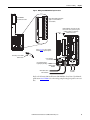
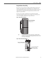
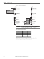
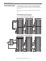
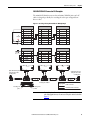
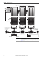
Figure 1 - Making 2090-K6CK-D44M Safety Connections
Use tie wraps (4x)
for stress relief.
Use shield clamps (3x) for
high-frequency bonding.
S1 ONLY
S1 ONLY
INPUTS
0 39 41 40 39 42 40 39 43 40 39 44 40
0 38 37 36 35 34 33 32 31 30 29 28 27 28 27 28 27 28 27
Turn clamps over for smaller
diameter cables.
AUX FEEDBACK
2 1
4 3
7 6 5
Refer to page 18 for safety, auxiliary
feedback, and I/O signal descriptions.
0 11 10 9 8
S1 ONLY
S1 ONLY
INPUTS
0 38 37 36 35 34 33 32 31 30 29 28 27 28 27 28 27 28 27
0 39 41 40 39 42 40 39 43 40 39 44 40
2 1
4 3
7 6 5
AUX FEEDBACK
Kit pin numbering corresponds to the IOD
connector. Pins 27, 28, 39, and 40 are given
multiple terminals to accommodate
additional connections.
28 27 26 25 24 23 22 21 20 19 18 17 15 14 0
0 11 10 9 8
Motion-allowed Jumper Installation
(applies to 2094-xx02x-M0x-S0
control modules)
S0&S1 W/S0 DISABLED
S0&S1 W/S0 DISABLED
28 27 26 25 24 23 22 21 20 19 18 17 15 14 0
28 27 26 25 24 23 22 21 20 19 18 17 15 14 0
2090-K6CK-D44M
Low-profile Connector Kit
Clamp
Shrink-wrapped
Insulation
Aux Feedback and I/O
Wires and Cables
Safety Wires
and Cables
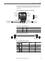
Refer to the Kinetix 6200 and Kinetix 6500 Modular Servo Drive User Manual,
publication 2094-UM002, for other wiring examples using low-profile connector
kits.
Rockwell Automation Publication 2094-RM002B-EN-P - May 2012
15