1
MICROMATIC
MicroMaticPowerPack
Service& SpecificationManual
Manufactured
by BVLControlsLtd.
Nor'heast Region
747 NorthFenwickStreet
Allentown,
PA 18103
(800)
1
345-3020
CentralRegion
213NorthThirdStreet
Rockford,
lL 61107
1 (800)435-6950
SoufheaslRegion
321Marianne
Street
Brooksville,
FL 34601
(888)
1
233-7827
Westen Region
'19761BahamaStreet
Northridge,
CA 91324
(800)
1
367-8852
Uh:iE
MICROMATIC
MICROMATICPOWERPACK
Manufacturedby BVL Controls Ltd.
AIR COOLED
PP4301(cwA-3)
1/3HP
FR22
1 1 5V o l t s
PP4302(cwA-2)
'U2HP
FR22
115Volts
PP4303(cwA-34)
314HP
FR22
208/230Volts
R134a
115 Volts
(MM-033) 1 1 3H P
K-PP-4301-EP
WATERCOOLED
PP4301-WC(cww-3)
314HP
1 1 5V o l t s
PP4302-WC(c\M^/-2)
'|2 HP
1'15Volts
PP4303-WC(c\ ^/V-34)
314HP
208/230Volls
MICRO
MATIC
GROUP
MICROMATIC
PRODUCTWARRANTY
partsandlaborwhenunit
BVLwarrants
thisproductfor one(1)fullyearincluding
is returned
to ourfactory(freightis notpartof the warranty)
or partsonlywhen
Partswillbe chargedto youraccount
repairhasto be doneat anotherlocation.
part.
andwillbe crediteduponreceiptof thedefective
ln Canadar
B.V.L.Controls
Ltd.
940Michelin
Laval,
H7L5Cl
Quebec
In U.S.A.:
Reslaurant
Selice of America
37Shuman
Avenue
Stoughton,
MA O2O272
Ub:iE
MICROMATIC
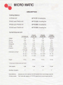
DESCRIPTION
Coolingdistance:
K-PP4301-EP
UP TO 75' of coolingline
PP4301and PP4301-WC
UP TO 125'of coolingline
PP4302and PP4302-WC
UP TO 250' of coolingline
PP4303and PP4303-WC
UP TO 350' of coolingline
Currontdrawperunit:
Voltage
K.PP43OI.EP
115
PP/130'l/
PP4301-WC
'115
PP13O2J
PP4302.WC
'|15
Startup
9.54
9.8A
10.6A
75A
7.14
7.94
5.34
R-22
R-22
Running
PP4303/
PP4303-WC
204t230
Reftigerant
R134a
Charge
l0 oz.
16oz.
21 oz.
36 oz.
18(low)
43 (low)
43 (low)
43 (low)
150(hish)
220(hish)
220(high)
220(high)
H: 13.0
Hr 28.5
H: 28.5
H: 29.5
W: 23.5
W: 16.75
W: 16.75
W: 18
O:22.0
Dr 26.5
D:26.5
Ot 26.5
70 lbs.
106lbs.
't13tbs.
134lbs.
4 gal.
12 gal.
12 gal.
'12qal
1"
1"
1"
1"
Pressurc
(inches)*
Dimensions
Weight
' DimensionsincludeDumDand motol
Tankcapacity
StyrofoamInsulation
ModelMl\4-033
Procor pumpwithcapacityof 50 GPHgravityfedto insurelongerpumplife.
All othermodelsi Gearpumpwithcapacityof 100GPHgravityfedto insurelonge.pumplite.
U}:iEMICROMATIC
OPERATION
PP43O1,PP4302,PP4303,PP4301-WC,
PP4302-WC
and pp43O3-WC
'L
2.
Connection:
a)
Connectone linefrom isolatedtrunklineto the DumDouflet.
b)
Connectsecondcirculationlineto the inletof the tub.
Fillingunitwithglycol
a)
Removetop deckfromthe unit.
b)
Fill the bath with Micro Matic Polar Fto glycol solution(mixed 2 %
parts water to 1 part grycol) solutionup to 2' from the return
tubang.
c)
Replacetop deckunitintothe bath.
d)
Make sure all re-circulation
lines are properlyconnectedand turn
the pumpmotoron by plugging
intothetopdeck.
Liquidlevelwill dropuntilcirculationlineis full
e)
Remove orange refillingcap, fill with water up to return line
(approximately
1"fromthecover).
D
Temperature
will dropto 30"Fon thermostat.
Note: Temperatureis set at 3eF from the factory.
To changetemperature,press menu until the temperatureis blinking.Set the
desiredtemperatureand pressmenuto set.
ub::?
MrcRoMATtc
OPERATION
K.PP43OI-EP
1.
2.
Connection:
a)
Connectone linefrom isolatedtrunklineto the pumpoutlet
b)
Connectsecondcirculation
lineto the inletofthetub.
Fillingunitwithglycol
a)
Removetop coverfromthe unit.
b)
Fill the bath with Micro Matic Polar Flo glycol solulion (mixed 2 %
parls water to 1 patTglycotl solutionup to overflowoutlet..
c)
Makesureall re-circulation
linesare properlyconnected
andlurn
thepumpmotoron.
Liquidlevelwill
dropuntilcirculation
lineis full
d)
Refillwith waterup to overflowoullet(approximately
1" fromthe
rop).
gauge.
Temperature
willdropslowly
to 30'Fonoutlettemperature
Note: Temperature
is setat 3eF fromthe factory.
0
gauge.
Temperature
willdropslowlyto 34'Fon inlettemperature
s)
Temperature
in returnline(inletgauge)shouldbe no morethan3'
or 4' morethanoutletgauge,if installation
wasdoneproperlyand
quality
trunklineis used.lf a trunkhousing
is insidea PVCchase
where there is water present,it will cause large temperature
differentials
between
thegauges.
h)
ReDlace
toocover.
U}:iEMICROMATIC
MAINTENANCE
Keepliquidlevelconstant
in glycolreservoir.
,..
1.
{
2.
Checkliquidmonthly
a)
lf levelis low.lill withwater.
b)
lf ice buildup, removeonegallonof waterand replacewith pure
Micro MaAcPolar Flo glycol.
Keep condensing
unit free of foreignmatterand cleaneverysix (6)
months.
M CFO
MAT C
MICROMATIC
TROUBLESHOOTING
Trouble
L
Excessivefoam
Cause
Warmwalk-incooler
Solution
A. Adjustcoolertempercturc
to 34" to
36€, (usequalitytheftnometer)
B. Check applied pressureto B. Adjust seftr,g on regulator fol
prcperpressurc
oarrel
Checkequipment
lines
D. Warmproduct
C. Checkthe physicalequipnent from
keg to faucet
D. Referto 5
Replacecompressorrelay,relay
relay or capacitor
2. Compressordoes A. Compressor
(no
notstart hum),
capactbr.
malfunction
butthefan motor
B. Measurevoltageacrosscommon
tuns,
voltage
B. Inadequate
and run tetminalon comqrcssor.
Voltagemust not drcp below90ok
of nted voltage.
failure
C. Compressor
3.
Compressorstarts
and continuesto
run untillreezeup
and will not cut off.
control
failure
A. Thermostat
B. Freonleak
Compressor doe6 A. Inadequate
voltage
not run but hums.
B . Slartingrelaymalfunction
C. Replacecompressot.
Replacethetmostat
B. Repairleak and recharge
A. Measurcvoltageacrcss common
and run teminal on compressor.
Voltagenust not drop below90%
of ratedvoltage
B, Replacestaftingrelay
Be surcto useconectrelay.Failure
to use corect rclay will cause
comprcssorfailuro.
C. compressormalfunction
C, Replacecompressor
M C BO
MAT C
MICROMATIC
Cause
Trouble
5.
Solution
Defective Pump (checkmotor
arso,l
Warmb.er
Check retum line in reseNoir for
liquidflow.Replacepump
B . Defectivemotor(checkpump B. Replace
motor
arsoJ
c.
Reftigeration
unit not running
D . Conduit
lines
overheatedarea
located
Removelron any hot water pipes
or kitchenarea silh saoveor g/ass
washer.
In
E. Conduitlinesfloodedin PVC
chase.
Removelinesfrcm PVC,thoroughly
dry PVC and rcpai or rcplace
conduitas needod.
F. Uninsulated
or poorlyinsulated
lines
A lines should bo fully insulated
trcmcoolerinlo dispenser.lncludes
glycol lines from power pack into
cooler.
G. Thermostat
G. Adjust tenpenture
setfing.
H. Condenser fan motor not
woaKrng
to
colder
Replacecondenserfan motor.
l.
Freonleak
L
Repairleak and recharge.
J.
Dirtycondenser
J.
Cleanlhe condenser
K. Condensationinside conduit K
(maybe causedfrom
insulatjon
cleaninglines)
Check trunk housing in areas lor
drcoping or /ow spots, sprl
insulation approximately 5" and
sepa/?te.Allow any waterto dmin,
thenairdry, the sea/c/osed.
L. Warmwalkin cooler
Check temperclure of walk-in
coolerJiquid temperaturc, set
coolarat 34'to 360.
L.
Uh::E
MICROMATIC
ElectronicTemperature
Controlwith Display
ChangingTemperature
Units
Pressthe Up and Downbuttonssimultaneously
to togglebetweeno F ando C.
Note: The Keypad Lockjumper must be in the unlockedposition(instaled)
before adjustingthe control.If the keypadis locked,pressing buttonshas no
effecton the control.
Setting the Setpoint
beforesettingthe setpoint,be surethe controlis set to the temperatureunitsyou
wantto use,Celsiusor Fahrenheit.
To viewandadjustthe setpoint,
usethefollowing
method:
1. Pressand holdthe Meru buttonfor abouttwo (2) secondsuntilthe display
changesto flashingSP.
Note: lf no enties are madefor thitty(30) seconds,the controlreveftsto
the temperaturedisplay.
2. Pressthe Menubuttonagain.Thecurrentsetpoant
is displayed.
3. Pressthe Up or Down buttonto adjustthe setpointtemperature.
4. Press the ,ltenu button to save. The displavthen returnsto the sensor
temoerature.
Note: lf the Menu bufton/:snof pressedafterchangingthe setpoint,the
controlrevedsto the setpointvaluepreviouslyprogrammedintothe A419.
FunctionRangesand Settings
Function
S P Setpoint
Range
-3Oto 212' F
C34to 100"C)
d t F Differential
1 to 30o(F or C)
ASd Anti-short
CycleDelav
0 to 12 minutes
oFs TemperatureOffset
0 to 50o(F or C)
S F SensorFailureOperation 0 = outputoff
1 = outputon
FactorySettinq
30
5
1
0
'l
IIb:iEMICROMATIC
Note: Operationat Extremes: lf the combination
of setpointplusor minusthe
differentialfallsoutsidethe temperature
range(30o F to 2120F [-34. C to 100a
Cl), the 4419 operafesas fol/ows.'
Cooling/Cut-in: lf the contrclis operatingin Cooling/Cut-in
mode and setpoint
minusdifferentialis lessthan -30" F, the controlswitcheson at setpointand off
whenthe temperature
dropsbelow-30oF (-34oC).
Heating/Cut-in: lf the controlis operatingin Heating/Culinmode and setpoint
plus differentialis greaterthan 212oF (00'C), the controlswitcheson at
setpointand offwhen the temperature
exceeds2120F (100oC).
Cooling/Cut-out: lf the control is operatingin Cooling/Culoutmode and
setpointplusdifferentialis greaterthan 212' F (100"C), the controlswitcheson
whenthe temperature
exceeds212oF (100' C) and off at setpoint.
Heating/Cut-out: lf the control is operatingin Heating/Cut-out
mode and
setpointminus differentialis iess lhan -30' F (-34' C), the controlswifcheson
whenthe temperature
dropsbelow-30"F C34"C) and off at setpoint.
SettingOtherFunctions
To set the Differential(dlF),Anti-ShortCycle Delay(ASd),TemperatureOffset
(OFS),or SensorFailure(SF)operation,
usethefollowing
method:
Orderof the Functions
1. Pressand holdthe Menu buttonuntilthe displaychangesto flashingSP.
Thiswilltakeabouttwo (2)seconds.
NOTE: lf no enties are made for thitty (30) seconds while
programming /s /n progress, the controlrevefts to the temDerature
display.
2. Press the Up ot Down button repeatedlyuntil the desired function is
displayed.
3. Pressthe Menubuttonto displaythefunction's
currentvalue.
4. Pressthe Up or Downbuttonuntilthedesiredvalueis displayed.
5. Pressthe Menubutlonto savethe newvalue.The disolavthen returnsto the
sensortemDerature.
MICRO
MAIIC
MICROMATIC
NOTE: lf you do not pressthe Menu bufton after settingthe new
value, the control revefts to the previouslyprogrammedvalue for that
function.
Checkout
Beforeapplyingpower,make sure installation
and wiring connectionsare
job
accordingto
specifications.After necessaryadjustmentsand electrical
connections
have been made,put the systemin operationand observethe
controlfor at leastthree(3) completecyclesbeforeleavingthe installation.
Troubleshooting
lf the controlsystemdoes not functionproperly,verifythat the unit is wired,
configured
and set properly.
lf the problempersists,
procedures
usethefollowing
to determine
the causeof the problem;
1. Checkfor propersupplyvoltageto the,A419control.
WARNING: Riskof ElectricalShock.
Highvoltagemaybe presenlat electrical
terminals
and otherexposedinternalmetalsurfaces.
Avoid
contactwith all metalsurfaceson controlwhen
coverts removeo.
Removethecoverby loosening
thefourcaptivecoverscrews.
o)
Usea reliable
AC voltmeter
to checkthe voltagebetweenthe COM
and 120Vor 240Vterminalson line voltagemodelsand the two
24Vterminals
on low-voltage
models
The voltage must be between 20 and 30 VAC for 24 volt
applications,
102 and 132VAC for 120 volt applications,
177 and
'fot
264 VAC 2081240volt aDDlications.
lf the voltagereadingis withinthe requiredrange,proceedto Step
2.
lf the voltagereadingis not withinthe requiredrange,checkthe
powersourceandinputpowerwiresfor problems
vpneb.
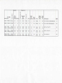
e
99pac'tI
PIMP
Gallds
PsHour
IGPHI
Punp
ilotor
HP
EC033
5"Hx i91/2',Wx1S1/2 D{incrude
MM,033
PP4301-EP E@nomY
CWA3
PP4301
1l3
P€mlum
RrsA
PesE
lz
lso r2
s!/W? @!!?rryers..i!t1
2300
250
32
12
4A
1/3
Gear
a0
1,3
Gear
a0
t3
3 H r 2 3 1 / 2W r 2 2 D ( i n c u d dp u m p )
2 a1 t 2 H x 1 7 W x 2 7 O