1
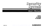
4120EC
SECURITY SYSTEM
USER’S MANUAL
N4861V4 9/92
TABLE OF CONTENTS
lNTRoDucTloN
..... ........ . ....... ........ ........ ........ ........ ........ ............... ......3
FIRE AND BURGLARY PROTECTION
ENTRY/EXITDELAYS
.. .. .. .. ... .. .. .. ..... .. .. .... .. . .. .. ...... . .. .. .....4
. .. .. .. ... . .. ... .. .. .... .. .. ... .. .. .. .... ... .. ...... .. .. .. ..... .. .. .. .. ... .
SECURllY
CODES .... .. .. .... .. . .... ... . .. .. ... .. ..... . .. .. ... .. .. .. .... .. .. . ...... .. .. .. .. ...5
DURESS
CODE ..... ... ..................... ......................................................5
FUNCTIONSOFTHECONSOLE
DlsmMING
mEsYswM
cHIMEmE
.. .... .. .. .. . .. .. .. .. .. .. . .. ...... .. . .. .... .. .. .. ... .. .. .. .. . 6
ANDslLENclNG
AMRMs
. .. .. .. ... .. ... .. .. .. ..... .. . ...8
.. .. .. .... .. .... ... .. .. .. .. .... .. . .... .... .. .... . .. .. .. .. .. .. .... ... .. ........ .. . ....8
CHECKING FOROPEN ZONES . ... . .. .... .. ..... .. .. ... .. .. .. .. .... . .. ...... .. .. . .... .. .... . 9
Bypassing
PRoEcTloN
zoNEs
. .... .. .. ... .. .. .. ......<.. .... .. . ...... .. .. .. ..... .. ...9
ARMINGPERIMEIERONLY(STAY/lNSTANT)
ARMINGALLPROTECTION
. .. .. .. ... .... .. ... .. .. .. ... .. .. .. .......10
(AWAYMIMXIMUM) . .. .. .. ... .. .. ... .. .. .. ... .... .. .......11
PANlc KEYs . ...... .... ... . .. ... .. .... .. .. .. ... .. .. .... .... .. ... .. .. .... .. .. ..... .. .. .. .. .. ... ...l2
TESTINGTHESYSTEM
. .. .... .. .. ... .. .. .... .. .. ... .. .. .. ...... . .. .... .. .. .. .. ... .. .. .. ......13
mouBLEmNDmloNs
FIRE
ALARM
.. .... .. .. .... ... .. .... .. .. ..... .. .. .... .. . ...... .. .. .. ... .. .. .. ......l4
SYSTEM ............................... ..........................................l5
NATIONAL FIRE PROTECTION
Emergency
Evacuation
SUMMARY
OF AUDIBLE
PRoEcTDN
zoNEs
ASSN. RECOMMENDATIONS
.. .. .. .. .... . .. .. .. .. .. .. . .. .. .. .... .. . .... .. .. .. ... .. .. .. .. ....l7
NOTIFICATIONS
Functions
EMERGENCYPHONENUMBERS
GLOSS~Y
...............................................l8
LlsT .. .. .. .. .. .. ... .. ...... .. .. ... .. .. .. .... . .. .... .. .. .. ... .. .. .. .. ..l9
QUICK GUIDE TO SYSTEM
OWNER’SINSURANCE
.....................16
.................................................l9
.. .. .... .. ... .... .. .. ..... .. .. .... .. . ...... .. .. ..... .. .. ..2O
PREMIUMCREDIT
REQUESTFORM .. .. . .. ... .. .. ... .. ...21
.. .. .... .. .. ... . . .... .. .. .. .. .. .. ... .. .. .... .. .. . .... .. .. .. .... ... .. .. .. .. .. .... .. . ...23
FCCSTATEMENT . .. .. .... .. .... . .. .... .. .. .. ... .. .. .... .. .. .. ... .. .. .... .. .. ... .. .. .. .. .... . ...25w
~ELIMITATONS
-2-
OF WISAMRM
SYSEM
.. .... .. . .... .. .. ... .. .. .. ... .. .. .. .......26
INTRODUCTION
Congratulations on your ownership of a VISTA Security System. You’ve made a
wise decision in choosing it, for it represents the latest in security protection
~chnology today.
Basically,
this system offers you
three forms of protection: burglary,
fire and emergency. To realize the
system’s full potential, it is important
that you feel comfortable in operating
it. Your system consists of at least
one Console
which provides
full
control of system operation, various
sensors which provide perimeter and
interior burglary protection,
plus a
selected
number
of strategically
placed
smoke
or
combustion
detectors designed to provide early
warning in case of fire.
The system
uses microcomputer
technology to monitor all protection
zones
and system
status
and
provides appropriate
information for
display on the Console(s) used with
the system, and initiates appropriate
alarms. When programmed to do so,
the
system
can
also
transmit
appropriate alarm or status messages
over the phone lines to a central alarm
monitoring station.
P.
ItiEr=T
r
@aEiibiEq
EI1313
m,,
W,..s
9,?.ss
Eimm
.,..
Immm
m
Cc.x
Eimm
L..
J
v
4127
4137
THE DISPLAY CONSOLES feature a multifunction,
12-key digital keypad,
and uses a fixed-word English language/zone
numeric LCD display which
displays the nature and location of all occurrences.
The consoles also have a
built-in sounder. There are two fixed word consoles available. The 4137 features
backlit keys, while the 4127 features a compact design (its keys are not backlit).
–3-
FIRE & BURGLARY
PROTECTiON
One or more sensing devices will have
been assigned by the installer of your
alarm system to each of the various
protection
zones
in your system
(although not every zone may have
been used). For example, the sensing
device on your Entry/Exit door may
have been assigned
to zone 01,
sensing devices on windows in the
master bedroom to zone 02, and so on.
These numbers will appear on the
display when the respective zone is
faulted.
The fire protection
portion of your
security system (if used) is always on
and will sound an alarm if a fire
condition
is detected.
Refer to the
FIRE ALARM SYSTEM section for
important information concerning fire
protection,
smoke
detectors
and
planning emergency exit routes from
your house.
ENTRY/EXIT
DELAYS
Your system was programmed by the
installer with a preset entry delay time,
during which the system must be
disarmed upon entering or an alarm will
occur. This feature
allows you to
reenter through the entry delay door
without setting off the alarm. A slow
beeping will sound at the console to
remind you to disarm the system. The
entry delay feature can also be turned
off for greater security when sleeping
or while away for extended periods of
time (INSTANT & MAXIMUM modes).
A preset
exit
delay
was
also
programmed to allow you time to leave
the premises without setting off the
alarm after arming the system. See
your installer for your delay times.
-4–
The burglary protection portion of your
system must be armed before it will
sense burglary
alarm condition
When an alarm occurs, both th~
console and external sounders will
sound, and a message in the Display
Window
will identify
the zone(s)
causing the alarm. In addition, if your
system is connected
to a central
monitoring station, an alarm report will
be sent. Disarming the system will
stop alarm sounding. Your system
provides
four modes of burglary
protection:
STAY, AWAY INSTANT
and MAXIMUM, and even allows you
to BYPASS
selected
zones
of
protection while leaving the rest of the
system armed. The system also
provides a CHIME mode, for alerting
users to the opening and closing of
doors and windows while the system
is disarmed.
Refer to the other
of
this
sections
manual
for
procedures for using these features.
Exit
Entry
Delay:
Delay:
o
seconds
o
seconds
Delays may be from 15 to 225
seconds in non-UL installations, but
no more than 60 seconds for Ex
delay or 45 seconds for Entry delayfor a UL Listed Household burglary
application.
SECURITY
CODES
At the time of installation,
your
installer programs a personal fourdigit code, known only to you and
yours. This code must be entered
when
performing
most
system
functions,
including
arming
and
disarming
of the system.
As an
additional
safety feature,
up to 6
temporary codes can be assigned for
use by those not having a need to
know the master code. Temporary
codes are assigned single-digit “User
numbers”
from 3 to 8.
Before
assigning a temporary code though,
be sure it does not conflict with the
DURESS code (see DURESS CODE
section). Note that the master code
remains
in effect even when a
temporary code is assigned.
QUICK ARMING: Note that if “Quick
Arming” was programmed
by the
installer, the [#] key can be pressed in
place of the security
code when
arming the system. The security code
is always required when disarming the
Assign
or
deiete
To
TemDorarv
Codes:
E;ter Ma;ter code.
i Press CODE [8] key.
3. Enter User Number to be assigned
or deleted (3-8).
4. To assign a code, enter temporary
code for that User Number.
To delete a code, enter Master
Code for that User Number.
5. The Console will beep once when
procedure
has been completed
successfully.
NOTE:
Users to whom temporary
codes have been assigned should not
be shown how to bypass protection
points unless they have a need to
know. It is also recommended
that
obvious codes such as 1111 or 1234
not be assigned.
/
/
}
/
/
coosik
DURESS
(WHEN
I
il
I
1
I
QLicx
AJIM
XEY
(lF PROGR#MME~
CODE
FORCED
TO DLSARM/ARM
Enter the first three digits of the
security code. Increase the final digit
by one and then press OFF (or
AWAY, etc. if arming the system).
The system will disarm (or arm), but
can silently notify the central station
of your situation, if that service has
been provided.
For example, if the Normal security
code is”1 23 4“, the Duress security
code is”1 23 5“.
UNDER
THREAT)
IMPORTANT
●
●
●
This code is useful only when
connected to a central station.
Duress code capability
is not
present for codes ending in 9.
Users of tempxaty
codes must be
instructed
to enter their codes
carefully to avoid the possibility of
accidentally
entering the Duress
code.
-5-
u
FUNCTIONS
OF THE CONSOLE
1. DISPLAY WINDOW:
Refer to the
FIXED WORD DISPLAY CONSOLE
System Status Display table on the
next page for a list of messages that
might
appear
along
with
their
meanings.
2. OFF KEY:
Disarms the burglary
portion of the system, silences alarms
and audible trouble indicators,
and
clears visual alarm trouble after the
problem has been corrected.
3. AWAY KEY:
Completely
arms
both perimeter and interior burglary
protection for backup protection
by
sensing
an intruder’s
movements
through protected interior areas as well
as guarding doors, windows, etc. Late
arrivals can enter through an entry
delay zone without causing an alarm if
the system is disarmed
before the
entry delay time expires.
4. STAY KEY:
Arms the perimeter
burglary protection,
guarding doors,
windows and other perimeter protection
points, and sounds an alarm if one is
opened.
Interior
protection
is not
armed, which allows movement within
your house without causing an alarm.
Late arrivals can enter through an
entry delay zone without causing an
alarm if the system is disarmed before
the entry delay time expires.
5. TEST
KEY:
Tests
the
a!arm
sounder
if disarmed.
Refer to the
TESTING THE SYSTEM section for
test procedures.
6. BYPASS
KEY:
Re m eves
individual protection zones from being
monitored
by the system. Displays
previously bypassed protection zones.
7. CHIME KEY: Turns on & off the
CHIME mode. When on, any entry
through a delay or perimeter zone
while the system is disarmed
will
cause
a tone to sound
at the
Console.
-6-
8. [#] KEY: Permits ARMING of the
system without use of a security code
(“Quick Arm”, if programmed to do sc
Used to enter y~
9. KEYS O-9:
individual security access code(s).
10. CODE KEY: Allows the entry of
additional
user codes that can be
given to other users of the system.
When
11. [*] READY
KEY:
depressed prior to arming the system,
the console will display all open
protection zones.
Arms in
12. INSTANT
KEY:
manner similar to STAY mode, but
turns off the entry delay period,
offering greater security while inside
and not expecting any late arrivals,
An alarm will occur immediately upon
opening
any perimeter
protection
point, including entry delay zones.
13. MAXIMUM
KEY:
Arms in
manner similar to AWAY mode, but
eliminates the entry delay period, thus
providing
maximum protection.
An
alarm will occur immediately
upon
opening
any
protection
point,
including entry delay zones.
14. POWER
INDICATOR:
(GREEN) Lit when primary power is
on. If off, system is operating on its
backuD batterv oower. CALL YOUR
INSTALLER IMMEDIATELY.
(RED~
15. ARMED
INDICATOR:
Lit when the system has been armed
(STAY,
AWAY,
INSTANT
or
MAXIMUM).
16. INTERNAL
SOUNDER:
Source of audible internal warning and
confirmation
sounds,
as well as
alarms (see “Summary
of Audible
Notifications”).
\
I
\
\
IIIm
-.
\
....
/
/
/
.... /
p“”‘--”-‘ ‘= ‘
FIXED
AWAY
STAY
INSTANT
BYPASS
NOT READY
READY
NO AC
‘ AC
CHIME
El-ARM
CHECK
FIRE
WORD
DISPLAY
CONSOLE
System
Status
Displays
All burglary zones, interior & perimeter, are armed.
Perimeter burglaty zones, such as windows & doors, are armed.
Perimeter burglary zones armed and entry delay is turned off.
One or more burglary protection zones have been bypassed.
Appears when burglary portion of the system is not ready for
arming (due to open protection zones).
The burglary POrtion of the system is ready to be armed.
Appears when AC power has been cut off.
Appears when AC power is present.
Aooears when the CHIME_ feature is activated.
Appears when an intrusion has been detected and the system is
armed (also appears during a Fire alarm). Accompanied by the
protection zone ID in alarm.
Appears when a malfunction is discovered in the system at any
time or if a fault is detected in a FIRE zone at any time or in a
DAY~lGHT burglaty zone during a disarmed period.
Accompanied by a display of zone number in trouble.
Appears when a fire alarm is present. Accompanied by a display
of the zone in alarm.
IMPORTANT!:
When using the keypad to enter
codes and commands, sequential key depressions
must be made within 3 seconds of one another If 3
seconds elapses without a key depression, the entry
~is abortad and must be re eated from its b innin .
-7-
DISARMING THE SYSTEM
AND SILENCING ALARMS
(FOFi
AWAY,
STAY,
INSTANT,
AND
PROCEDURE
1. Enter security code and press
OFF [1]. The READY
message
will be displayed and the console
will beep once to confirm that the
system is disarmed,
unless an
alarm has occurred.
2. If an alarm has occurred, note the
zone number displayed and repeat
step 1 to restore the READY
message display. If the message
will not display, go tot he displayed
protection zone and remedy the
fault (close windows, etc.). If the
fault cannot be remedied, notify
the alarm agency. ~~
MAXIMUM
ARMING)
RESULT
Any alarm sounders will be silence
ALARM
and
zone
number
(~
displayed) will clear only when the
open sensor is closed.
A fire alarm is indicated by
both FIRE and the zone
the Console. These will
when the fire zone is again
a display of
number on
clear only
intact.
-
See “SUMMARY
OF AUDIBLE
for
section
NOTIFICATION”
information which will enable you to
distinguish
between
FIRE
and
BURGIARY alarm sounds.
ENTER
PRESS
OFF
CHIME
MODE
ONLY WHEN THE SYSTEM IS DISARMED)
To turn
Chime
Mode on, enter
the security
code and press the
CHIME
[9] key. The CHIM
L
message will appear.
(THIS FEATURE IS FUNCTIONAL
Your system can be set to alert you to
the opening of a door or window while
it is disarmed by using CHIME mode.
When activated,
three tones will
sound at the Console whenever a door
or window is opened, and the Not
Ready message will be displayed.
Pressing the READY
[*] key will
display the open zone number. Note
that Chime mode can be activated
only when the system is Disarmed.
To turn
Chime
Mode off, enter
the security
code and press the
CHIME [9] key again. The CHIME
message will disappear.
h
,
L
la&lei
fiiaixl
rala~
cd
m
0-”
a
●
’--
qm>
-- ‘
-81
ENTER
CODE &
PRESS
CHIME
CHECKING
BEFORE
WINDOWS
FOR OPEN ZONES
ARMING
YOUR
SYSTEM,
AND OTHER PROTECTION
ALL
PROTECTED
DOORS,
ZONES MUST BE CLOSED.
PROCEDURE
lftheNOT
READY messageis
displayed priorto arming, check
for open zones by depressing
and releasing the READY [*]
key (do not enter code first).
All open protection points will be
displayed.
These” pints
must
be either closed or bypassed
before
the system
can be
armed. The READY message
will be displayed
when all
protection
zones have been
either closed or bypassed.
BYPASSING
PROTECTION
ZONES
(FOR ARMING WITH ONE OR MORE ZONES SELECTIVELY
PROCEDURE
1. System must be disarmed
Enter security code.
first.
2. Press BYPASS [6] and enter zone
number(s) of zones to be bypassed
(e.g.,
01,
02,
03,
etc.).
Important!
All single-digit
zone
numbers must be preceded by a
zero (example, enter 01 for zone 1).
3. When finished entering all zone
numbers to be bypassed, wait for
bypassed zones to be sequentially
displayed before arming.
message will be
4. The BYPASS
displayed indicating the presence
of one or more bypassed zones.
the
system
as usual.
5. Arm
Bypassed zones are unprotected
and will not cause an alarm when
violated while system is armed.
UNPROTECTED)
NOTES:
1. All bypasses are removed when an
OFF sequence (security code plus
OFF) is performed.
2. Temporary
users should not be
shown how to bypass protection
points unless they have a need to
know.
DISPLAYING BYPASSED ZONES
(For determining
what zones have
been previously bypassed)
1. Enter security
BYPASS [6].
code
and
press
2. Wait for all bypassed zones to be
sequentially displayed.
LIMITATIONS
Fire or emergency zones cannot
be bypassed.
●
Arming
the
system
before
bypassed
zones are displayed
nullifies all bypasses.
●
/A
\
Eli cata
U
●
-
●
-.
–-@
qi_rmg
-9-
ARMING
PERIMETER
ONLY
STAY:
STAYING
HOME, EXPECTING
LATE ARRIVALS
INSTANT:
STAYING
HOME, NO LATE ARRIVALS
EXPECTED
PROCEDURE
1. Enter the security code when the
READY message is displayed.
2. Press the STAY [3] or INSTANT
[71 key, depending on arming mode
desired.
STAY KEY RESULT
Arms sensors guarding doors and
windows, with entry delay on. Late
arrivals can enter through the entry
delay zone door and disarm the
system within the entry delay period
without causing an alarm. See your
installer for actual delay times set for
your system.
Alarms
will occur
instantly when any exterior protection
point is violated,
except the entry
delay zone door, which will activate an
alarm if the system is not disarmed
within the entry delay period. Interior
protection
points are disarmed
to
permit
freedom
of
movement
throughout the interior.
–lo-
3. The armed state message will ~
displayed, accompanied by three
beeps from the Console. Exit delay
begins. Perimeter protection is in
effect immediately,
except entry
delay zone if STAY
key is
pressed.
INSTANT
KEY RESULT
Arms sensors guarding
doors awindows, with entry delay off. Alarms
will occur instantly when any exterior
protection point is violated, including
the entry delay zone door.
Interior
protection
points are disarmed
to
permit
freedom
of
movement
throughout the interior.
ARMING
ALL
PROTECTION
AWAY: NO ONE STAYING
HOME
MAXIMUM:
NO ONE STAYING
HOME,
=ROCEDURE
,. Enter the security code when the
READY message is displayed.
2. Press
the
A W A Y [2]
MAXIMUM [4] key, depending
arming mode desired.
or
on
MAXIMUM
3. The armed state message will be
displayed,
accompanied
by two
beeps from the Console.
Exit
delay begins [if programmed,
a
slow beeping will sound throughout
the exit delay period].
Complete
system protection
is in effect
immediately,
except entry delay
zone if AWAY key is pressed.
/
\
\
SECURITY
●
✎ ✎
-mm
-
.
mlam
D
AnMCO
● POWm
&WAY KEY RESULT
Arms all perimeter
and interior
sensors, with entry delay on. You may
exit during the exit delay period and
reenter through the entry delay zone
door (and disarm the system within
the entry delay
period)
without
causing an alarm. See your installer
for actual delay times set for your
system. Alarms will occur instantly
when any protection point, interior or
exterior, is violated, except the entry
delay zone door if AWAY
key
pressed, which will activate an alarm if
the system is not disarmed within the
entry delay period.
qmq
MAXIMUM
KEY RESULT
Arms all perimeter
and interior
sensors, with entry delay off. You
may exit during the exit delay period,
BUT alarms will trigger instantly upon
reentering, or when any protection
point, interior or exterior, is violated.
This mode is suggested when the
premises will be vacant for extended
periods of time such as vacations,
etc., or when retiring for the night and
no one will be moving
through
protected interior areas.
-11-
PANIC
(FOR
KEYS
MANUALLY
ACTIVATING
SILENT
There are two possible combinations of
paired
keys
that
are
installer
programmable
emergency functions.
See your installer for the functions that
have been programmed
for these
emergency
key
pairs.
Typical
functions that might be programmed
are Silent Police,
Audible
Police,
Personal Emergency, and Fire.
To
use
a
Panic
function,
simpiy
press
both keys of the
assigned
pair at the same time
and hold down for at /east two
seconds.
Active Panic Functions:
KEY[*]+[q:
(displayed
KPf[q
+
es zone W)
[3]:
(displayedaszone%)
A
-12–
AND/oR
AUDIBLE
ALARMS)
RESULT
If programmed for silent emergency b
your installer,
and the system ~
connected
to
a central
alarm
monitoring station, the control will send
a silent alarm signal to the central
station, but there will be no audible
alarms
or visual
displays.
If
programmed for audible emergency by
your installer, a loud, steady alarm will
sound at your console and at any
external
sounders
that
may be
connected.
A personal emergency alarm will notify
the central station (if connected) and
will sound at consoles,
but not at
external belis or sirens.
A fire alarm will send a fire alarm
message to the centrai station and will
uniquely sound external bells and
sirens.
TESTING
(TO
BE
THE SYSTE M
CONDUCTED
WEEKL .Y)
1. Disarm the system.
Enter security code and press the
TEST [5] key.
3. The external
sounder
should
sound for3 seconds and then turn
If the sounder
does not
off .
sound, it may be due to dialer
communication
activity.
Wait a
few minutes and try again. If the
sounder still does not sound, CALL
FOR SERVICE IMMEDIATELY.
4. Turn the Test mode off by entering
the security code and preesing
OFF.
ARMED SYSTEM TEST
Important!
A message will be sent
to the central alarm monitoring station
(if the system is so connected) during
the following tests. Notify them that a
test will be in progress.
Note:
A display of FC on your
console indicates
a failure of the
system to communicate with the alarm
monitoring station .
1. Arm the system and fault each
zone
(open
and close
each
protected
doors
or window).
Silence the alarm sounder(s) each
time by entering
your ~ecurity
code and pressing OFF. Check
that
Entry/Exit
delay
zones
provide the assigned delay times
(see page 4).
panic
2. Check the keypad-initiated
alarms, as indicated on page 12,
by pressing keys [*]& [#], and [#]
& [3]. If the system has been
for
programmed
audible
emergency, the console will emit a
loud, steady alarm sound.
When [*] and [#] are pressed,
flLtl RM*
and “99” will
be
displayed.
When [#] and [3] are pressed,
RLfl RM*
and “96’
will be
displayed.
●tlLRRM
and/or FIRE
may be
displayed on the consoles.
If a certain set of keys has been
programmed
for silent
panic,
there
will
be no alarms
or
displays;
however,
a silent
message
will be sent to the
alarm monitoring
station if the
system has been so connected.
3. Disarm the system (security code
plus OFF).
4. Notify the alarm monitoring station
(if connected to one) that all tests
are finished and verify results with
them.
13 -
TROUBLE
CONDITIONS
The word CHECK on the Console’s display, accompanied by a rapid “beeping” at the
console, indicates that there is a trouble condition in the system. The audible warning
sound for CHECK conditions may be silenced by pressing-any key.
TYPICAL
“CHECK”
DISPLAYS
1. A disolay of CHECK accompanied bv a
display hf one or more zone num6ers
indicates that a problem exists with those
zone(s), First, determine if the zone(s)
displayed are intact and make them so if
they are not. If the problem has been
corrected, the display of the zone
number(s)
and
CH EC K
should
disappear. If not, key an OFF sequence
(Code plus OFF) to clear the display. If
the display persists, CALL FOR SERVICE
IMMEDIATELY.
2. A display of FC at the Console indicates
that a failure has occurred
in the
telephone communication portion of your
system.
CALL
FOR
SERVICE
IMMEDIATELY.
3.
A display of OC indicates an open
connection from the console to the
control.
CALL
FOR
SERVICE
IMMEDIATELY.
SERVICING
4. A disolav of CC indicates the control is
in cor’nm’unicationwith a remote station.
Effectively, the control is disabled
during this time. Note that all alarms and
troubles
will
be
restored
and
annunciated
when the system is
returned to normal.
5.
POWER FAILURE:
If the POWER
indicator is off, operating power for the
system has stopped and is inoperative.
CALL FOR SERVICE IMMEDIATELY. If
the POWER indicator is on, but the
message NO AC is displayed, the
Console is operating on battery power
only. If only some Ights are out on the
premises, check circuit breakers and
fuses
and reset
or replace
as
necessary.
CALL FOR SERVICE
IMMEDIATELY if AC power cannot be
restored.
INFORMATION:
Your local authorized service representative
is the person best qualified to
service your alarm system. Arranging some kind of regular program with him is
advisable. Your local service representative is:
-14-
FIRE ALARM
SYSTEM
(IF INSTALLED)
Your fire alarm system (if installed) is on 24 hours a day, for continuous
protection.
In the event of an emergency, the strategically located smoke and
heat detectors will automatically send sgnals to your Control/Communicator,
“ - ~ering a loud, interrupted sound from the Console. An interrupted sound will
be produced by optional exterior sounders. A FIRE message will appear at
your tinsole and remain on until you silence the alarm.
IN CASE OF FIRE ALARM:
1. Should you become aware of a fire
emergency before your detectors
sense the problem, go to your
nearest Console and manually
initiate an alarm by pressing the
panic key pair assigned as FIRE
emergency (if programmed by the
installer) and hold down for at least
2 seconds.
2. Evacuate all occupants from the
premises.
and/or
smoke
are
3. If flames
present, leave the premises and
notify your local Fire Department
immediately.
or smoke
are
4. If no flames
apparent, investigate the cause of
the alarm. The zone descriptor of
the zone(s) in an alarm condition
will be displayed at the Console.
Note:
“Approval
of the panel’s
burglar alarm functions does not fall
within the (California)
State Fire
Marshal’s area of jurisdiction.”
h
SILENCING
A FIRE ALARM:
1. Silence the alarm by entering your
code and pressing the OFF key.
To clear the display, enter your
code and press the O F F key
again.
2. If the Console does not indicate a
READY condition after the second
OFF sequence, press the READY
[*] key to display the zone(s) that
are faulted. Be sure to check that
smoke
detectors
are
not
responding
to smoke or heat
producing objects in their vicinity.
Should this be the case, eliminate
the source of heat or smoke.
not remedy
the
3. If this does
problem, there may still be smoke
in the detector.
Clear it by fanning
the detector for about 30 seconds.
has been
4. When the problem
corrected,
clear the display by
entering your code and pressing
the OFF key.
I
.,..,”,,-,
m_l_m I
Illln=n..”,0
●
-15-
NATIONAL FIRE PROTECTION
ASSN.
RECOMMENDATIONS
ON SMOKE
DETECTORS
With regard to the number and placement of smoke/heat detectors, we subscri~
to the recommendations contained in the National Fire Protection Association’s
Standard #74 noted below.
Early warning fire detection is best achieved by the installation of fire detection
equipment in all rooms and areas of the household as follows: A smoke detector
installed outside of each separate sleeping area, in the immediate vicinity of the
bedrooms and on each additional story of the family living unit, including
basements and excluding crawl spaces and unfinished attics.
In addition, it is recommended that the householder consider the use of heat or
smoke detectors in the living room, dining room, bedroom(s), kitchen, hallway(s),
attic, furnace room, utility and storage rooms, basements and attached garages.
I
CONSOLE ~
F03M
WREN
d
m
DIN(NG
d>
m
Y
KITCHEN
I
mm
A
f--d
o
CCNTFOL
LIVING
RCC+l
‘i—
a
II
PLACE
DETECTOR
NEAR ALL
SLEEPING
AREAS
o
~R w.
I
fJ = %%,
PLACEMENT
SIREN
BEST RESIDENTIAL DETECTOR PLACEMENT
BETWEEN BEDROOMS AND REST OF HOUSE
I!!ii!2
BEDRGOM
BEDRcOM
A
-16-
,R
,0
MAXIMUM FLOOR
COVERAGE –
DETECTORS AT
TOP OF
STAIRWELLS
o
“E””m”
“o”-
o
EMERGENCY
EVACUATION
Establish and regularly practice a plan of escape in the event of fire. The
following steps are recommended by the National Fire Protection Association:
—
4. Assure that all bedroom doors are
Plan on your detector or your
shut while you are asleep. This will
interior and/or exterior sounders
prevent
deadly
smoke
from
warning all occupants.
entering while you escape.
2. Determine two means of escape
5. Try the door. If the door is hot,
from each room. One path of
check
your
alternate
escape
escape should lead to the door
route. If the door is cool, open it
that permits normal exit from the
cautiously. Be prepared to slam
building.
The other may be a
the door if smoke or heat rushes
window,
should your path be
in.
unpassable.
Station an escape
ladder at such windows if there is a
6. Crawl in the smoke and hold your
long drop to the ground.
breath.
3. Sketch a floor plan of the building.
7. Escape quickly; don’t panic.
Show windows, doors, stairs and
8. Establish a common meeting place
rooftops
that can be used to
outdoors, away from your h~use,
escape. Indicate escape routes
where everyone can meet and then
for each room. Keep these routes
take
steps
to
contact
the
free from obstruction
and post
authorities and account for those
copies of the escape routes in
missing.
Choose
someone
to
every room.
assure that nobody returns to the
house — many die going back,
EXAMPLES
m
.
ROOM
BATH
ROOM
I
‘m
@FLOOR
Ld
❑
❑
ID
0
FRONT
I
-
T
FLOOR
I
L
m
“\
0.
SUMMARY
OF
SOUND
CAUSE
LOUD, INTERRUPTED
FIRE ALARM
AUDIBLE
NOTIFICATION
DISPLAY
FlllE and RLflRM is displayed;
protection zone in alarm”is displayed.
Console & External
LOUD, CONTINUOUS
BURGURY/AUDIBLE
Console K External
EMERGENCY ALARM
R LFIRM is displayed; protection zone~
in alarm is also dkdaved.
. .
ONE SHORT BEEP
a. SYSTEM DISARM
a. Only REFiDVis displayed.
(not repeated)
b. SYSTEM ARMING
AlTEMPT WITHAN
OPEN ZONE.
b. NOT RE13DYis displayed, open
protection zone number is displayed.
c. BYPASS VERIFY
c. The bypassed protection zone
numbers are displayed. (One beep for
each number displayed.) BYPFISS
displayed.
TWO SHORT BEEPS
ARM AWAY OR
MAXIMUM
RUJRY and possibly lNSTFiNT are
dis.riaved.
THREE SHORT
BEEPS
a. ARM STAY OR
INSTANT
a. STfl Y and possibly INST13NT are
displayed
Console only
b. ZONE OPENED
WHILE SYSTEM IS
IN CHIME MODE.
b. CHIME displayed, open protection
zone number is displayed.
c. ENTRY WARNING**
c. No display.
a, TROUBLE
a. CHECK displayed. Troubled
protection zone is displayed.
b. AC POWER LOSS
ALER~’
b. NO RC displayed (may alternate with
other displays that may be present).
c. MEMORY OF
AIARM
c. F IRE and/or FILRRM is displayed;
zone in alarm is displayed.
a. ENTRY DEIJIY
WARNING
a. None during delay; Exceeding the
delay time without disarming causes
alarm.
Console only
RAPID BEEPING
Console only
SLOW BEEPING
Console only
‘If bell is used as external sounder, fire alarm is pulsed ring; burglary /audib’
emergency is steady ring,
●*Loss of system battery power is not indicated or annunciated by the console
(warnings are for loss of AC power only).
-18-
I
-
PROTECTION
ZONES
LIST
One or more sensing devices will have been assigned by the installer of your
alarm system to each of the various protection zones in your system (although
. not every zone may have been used). For example, the sensing device on your
ntry/Exit door may have been assigned to zone 01, sensing devices on
~indows in the master bedroom to zone 02, and so on.
ID numbers 01-08 represent sensor/detector protection points. ID number 96
and/or 99 represent “Panic” alarm codes assigned by the installer.
For your convenience, a chart has been provided which may be used to record
the specific protection points that have been assigned to each zone in your
system. Your installer will assist you in recording this information.
PROTECTION
POINT
DESCRIPTIONS
DESCRIPTION
ID
1
2
3
4
5
6
7
8
96
99
QUICK
GUIDE
TO ALARM
SYSTEM
FUNCTIONS
PROCEDURE
COMMENTS
Press [*]
To view faulted zones when
svstem not readv.
.
Arm System
Enter code
Press arming key desired
(AWAY.STAY.INSTANT,MAXIMUMl
Arms system in mode
selected.
Disarm System
Enter code
Press OFF [11
Disarms system and
silences alarms.
Bypass zones
Enter code,
Press BYPASS [6]
Enter zone numbers to be
bypassed (use 2digit entries)
Bypassed zones are
unprotected and will not
cause an alarm if violated.
Chime Mcde
Enter code
Press CHIME [9]
Console will sound if doors
or windows are violated
while system disarmed.
Test Mode
Enter code & press TEST [5]
Sounds alarm sounder.
IFUNCTION
kheck
Zones
k
-19-
Emergency
Alarm Monitoring
Phone
Numbers
Station:
Fire Department:
Gas/Electric
Company:
Neighbor:
Doctor:
Hospital:
Ambulance:
Emergency:
SERVICING
INFORMATION:
Your local authorized service representative
is the person best qualifi
to service your alarm system. Arranging some kind of regular program wl!u
him is advisable. Your local service representative is:
-20-
CREDIT
REQUEST
This form should be completed and forwarded
‘=wrier for possible premium credit.
to your homeowner’s
insurance
.. GENERAL
INFORMATION:
Insured’s Name and Address:
InsuranceCompany
I%lic.yNo.:
ADEMCO’S VISTA4120EC
❑
Type of Alarm:
❑
Burglary
Instanadby
B.
name
address
addresa
(Insert
Central Station U
C. POWERED
E.
SMOKE
B= Burglary,
BY:
❑
A.C. With Rechargeable
Quarterly
DETECTOR
BURGLARY
Monthly
Fire Dept. D
Power Supply
❑
Weekly
❑
Other
LOCATIONS
Kitchen
Living Room
1st Floor Windows
~
All Accessible Openings,
❑ Bedrooms ❑
❑ Dining Room ❑
DEVICE
Basement Door
~
3igrraura
❑
DETECTING
❑ Front Door ❑
G. ADDITIONAL
F= Fire)
Police Dept. D
Name and Address
❑ Furnace Room ❑
❑ Basement
❑
F.
Both
Setvicd by
NOTIFIES
TESTING:
❑
name
Local Sounding Device D
D.
Fire
Hall
LOCATIONS:
❑ Rear Door ❑ All Exterior Doors
❑ All windows ❑ Interior Locations
Including Skylights, Air Conditioners
PERTINENT
Attic
INFORMATION:
Date
and Vents
Complete
the reverse side of this form, detach from
manual and forward to your homeowner’s
insurance
earner for possible premium credit.
-22-
w
GLOSSARY
The following glossary of terms are used throughout the manual.
simply
RM/DISARM:
“Armed”
means that the burglary portion of
your system is turned ON and is in a
state of readiness. “Disarmed” means
that the burglary system is turned
OFF, and must be rearmed to become
operational.
However,
even in a
“disarmed”
state, “emergency”
and
“fire” portions of your system are still
operat”mrral.
KEYPAD:
This is the area on your
Console
containing
numbered
pushbuttons similar to those on
telephones
or calculators.
These
keys control the arming or disarming
of the system, and perform other
functions
which
were previously
described in this manual.
ZONE: A specific area of protection.
BYPASS: To disarm a specific area
of burglary protection while leaving
other areaa armed.
An area
of
DELAY
ZONE:
protection containing doors most
frequently
used to enter or exit
(typically, a front door, back door, or
door from the garage
into the
building). The delay zone allows
sufficient time for authorized entry or
exit without causing an alarm. Consult
your installer for the entry and exit
delay times that have been set for
your system during installation.
DAY/NIGHT
ZONE:
An area of
protection whose violation causes a
trouble indication during the disarmed
(DAY) mode and an alarm during the
armed (NIGHT) mode.
-23-
CANADIAN
DEPARTMENT
COMMUNICATIONS
(DOC)
OF
I
STATEMENT
NOTICE
The
Canadian
means
that
safety
Department
of Communications
the equipment
meets
certain
label
identifies
certified
telecommunications
The Departmentdoesnot guaranteethe
requirements.
equipment.
network
This certifice
protective,
equipment
operational
a
operateto the user’s
will
satisfaction.
Before installing this equipmen[,usersshouldensuredtat it is permissibleto be mnnectedto the
facilitiesof the localtelecommunications
company.The equipment must also be installed using en
acceptableMSthodof conrwakm.In somecases,the company’s inside wiring aasoaated with a single
Iirw
individual
extension
prevent
The
degradation
Repairs
may be
service
cord).
to certified
extended
should
be awere
of service
in mme
situations.
equipment
should
designatedby the supplier. Any
equipment
malfunctions,
disconnea
the equipment.
Users
should
ensure
by means
wstomer
may
be
made
repairs
give
lines
precaudon
may be particularly
and
internal
Caution:
User
should
made
the telecommunications
metallic
not attempt
pipe
system,
assembly
the a!mve
(telephone
conditions
may
not
Canadianmaintenancefacility
by the
company
that the electrical
water
important
connector
with
by an authorized
or alterations
for their own protecdon
telephone
of certified
that compliance
user
to this
cause
ground
connecdons
if present,
are
equipment,
to request
of the power
connected
or
the user
to
utility,
together.
This
in rural areas.
to make
such
connections
themselves,
contact the
but should
appropriate eiectrk inspecdon authority, or electriaerr, es appropriate.
The
Nu mber
Loed
be connected
(LN)
assigned
to a te!qhcme
on a loop may mnsist
the Loed Numbers
to each
loop which
terminal
of any combination
of all the devices
of devices
does
denotes
the percentage
to prevent
subject
not exceed
I
of the total Ioed’to
overloading.
Tlms termination
onfy to the requirement
that the total of
lcO.
AVIS
L%tiquette
du ministrbre
Mquette cede
s6curit6
des
fmdonnere
Avent
device
is used by the device,
que
acceptde
un service
possible
service
pefdculiers
normes
de protecticm,
n’assure
certeins
toutefois
d’exploitation
pas
K@honique
aux jacks
au moyen
que
et de
Ie matt%iel
a-dessus
aux installations
instal16 en suivartt
de I’entrepriee
dln
L’abonne
dispositif
ne do it pas
n’empbchent
Ies enterprises
dabonn6s,
&re
Ies fits int&ieurs
interne),
6nonc6es
Actuellement,
Ieur mat6riel
cas,
de Ie racmrder
doit 6galement
i%re prolongt%
eux conditions
situations.
qu’il est permis
Le mak$riel
peuvent
prolongateur
la conformit6
pas qua I’on raccorde
doit s’assurer
Dens
a Iigne unique
(cordon
qua
I’utiiisateur
de raczmrdemenl.
par certeirtes
A certeines
Le ministbre
de t&%ommunication.
individual
raccordement
est conforme
I
de I’utilisateur.
ca mat6riil,
locale
Canada identifieIe mat6riel homologu~. Cette
du
de t616cmmmunications.
~ la satisfaction
de I’entreprise
Communications
Ie mak%iel
n%eaux
d’insteller
m6thod
des
utilis6s
oublier
qu’il
de
est
pas la dc$gradatior
de t614communication
sauf dens
une
pour
homobgud
Ies cea preds
ne permet
pr6vus
par Ies tam
de oes entrepriaes.
Les m$perations de mat4rk4 homologu6 doivent &re effectkes pas un centre dentretierr Canadian
authoris6 d&.ign4 par Ie fournisseur. La mmpagnie de t.4irkammunicetions peut demander ~
Miliseteur de d6brancher un eppareil ~ la suite de reparations ou de modifications effecnkes per
hMisateur ou ~ cause de meuveis fonctionnement.
Pour se prnpre protection, I’utilisateur doit s“essurer que tous Ies fils de
mise
d’energie
m6telliques,
t$lectrique,
des Iignes
t616phoniques
reccod$s ensemble. Cette pkeution
Averiiasament:
racours
LUtilisateur
A un service
,.
~lC)
pourcentage
dispoeitif.
disfmeitifs,
lCK).
-24-
assign6
de la charge
La termineison
pourvu
tenter
des installations
~ dtaque
totate qui peut &re
du circuit
que la somme
deau
&la
terre
bouc16
des indices
de faire
dispositif
raccorde6
peut
ces
4ectriques,
&re
de tkarge
raccordements
pour
A un circuit
constitw$e
twiter
toute
16Mphonique
de n’importe
de I’ensemble
selon
ii doit avoir
Ie cas.
surcharge
boud6
quelle
des dispositifs
a, sent
rurales.
lui-m6me;
ou ~ un t$bctriuan,
terminal
de la source
s“il y en
est particulibrement importente clansIes r~tons
ne dcdt pas
dinspecdon
et des canalisations
indique
!e
utilis6 per m
combinaison
ne d6pease
de
pas
1
“FEDERAL
1
COMMUNICATIONS
COMMISSION
(FCC) STATEMENT”
is equipment has been test-ed to FCC requirements and has been found
~cceptable for use.
The FCC requires the following statement for your
information:
I
This equipment generates and uses radio frequency energy and if not installed
and used properly, that is, in strict accordance
with the manufacturer’s
instructions, may cause interference to radio and television reception. It has
been type tested and found to comply with the limits for a Class B computing
device in accordance with the specifications in Part 15 of FCC Rules, which are
designed to provide reasonable
protection against such interference
in a
residential installation. However, there is no guarantee that interference will not
occur in a particular installation. If this equipment does cause interference to
radio or television reception, which can be determined by turning the equipment
off and on, the user is encouraged to try to correct the interference by one or
1more of the following measures:
●
If using an indoor antenna, have a qualky outdoor antenna installed.
●
Reorient the receiving antenna until interference
●
Move the receiver away from the controlkommunicator.
●
Move the antenna leads away from any wire runs to the controlkommunicator.
●
is reduced or eliminated.
Plug the controlkommunicator
into a different outlet so that it and the receiver
are on different branch circuits.
If necessary,
radio/television
the user should consult
the dealer
technician for additional suggestions.
or
The user or installer may find the following booklet prepared
Communications Commission helpful: “Interference Handbook”
This booklet is available from the U.S. Government
DC 20402.
an
experienced
by the Federal
Printing Office, Washington,
L
The user shall not make any changes or modifications to the equipment unless
IIthorized by the Installation Instructions or User’s Manual.
Unauthorized
anges or modifications
could void the user’s authority to operate the
equipment.
I
IN THE EVENT OF TELEPHONE
OPERATIONAL
PROBLEMS
In the event of telephone operational
problems, disconnect the control by
removing the plug from the RJ31 X (CA38A in Canada) wall jack. We recommend
that your certified installer demonstrate disconnecting the phones on installation
of the system.
Do not disconnect
the phone connection
inside the
controlkommunicator.
Doing so will result in the loss of your phone lines. tf the
regular phone works correctly
after the control/corn municator has been
disconnected from the phone lines, the control/mmmunicator
has a problem and
should be returned for repair. If upon disconnection of the controkommunicator,
there is still a problem on the line, notify the telephone company that they have a
problem and request prompt repair service. The user may not under any
circumstances
(in or out of warranty) attempt any service or repairs to the
system. It must be returned to the factory or an authorized service agency for all
repairs.
-25-
‘w’””’”~
THE --LIMITATIONS OF THIS ALARM SYSTEM
While this system is an advanced design security system, it does not of’
~uaranteed protection against burglary or fire or other emergency. Any alasystem, whether commercial or residential, is subject to compromise or failure to
~arn for a variety of reasons. For example:
I Intruders may gain access through unprotected
openings or have the
technical sophistication to bypass an alarm sensor or disconnect an alarm
warning device.
I Intrusion detectors (e.g. passive infrared detectors), smoke detectors, and
many other sensing devices will not work without power. Battety operated
devices will not work without batteries, with dead batteries, or if the batteries
are not put in properly. Devices powered solely by AC will not work if their AC
power supply is cut off for any reason, however briefly.
Signals sent by wireless transmitters may be blocked or reflected by metal
before they reach the alarm receiver. Even if the signal path has been recently
checked during a weekly test, blockage can occur if a metal object is moved
into the path.
A user may not be able to reach a panic or emergency button quickly enough.
While smoke detectors have played a key role in reducing residential fire
deaths in the United States, they may not activate or provide early warning for
a variety of reasons in as many as 357. of all fires, according to data published
by the Federal Emergency Management Agency. Some of the reasons smoke
detectors used in conjunction with this System may not work are as follows.
Smoke detectors may have been improperly installed and positioned. Smoke
detectors may not sense fires that start where smoke cannot reach the
detectors, such as in chimneys, in walls, or roofs, or on the other side of
closed dmxs. Smoke detectors also may not sense a fire on another level of a
residence or building. A second floor detector, for example, may not sense a
first floor or basement
fire. Moreover,
smoke detectors
have sensing
limitations. No smoke detector can sense every kind of fire every time. In
general, detectors may not always warn about fires caused by carelessness
and safety hazards like smokirm in bed, violent extiosions.
esca~ina aas,
improper ‘storage of flammabl;
materials, overloaded
electrical ci~c~; “‘
children playing with matches, or arson. Depending upon the nature of the h v
and/or the locations of the smoke detectors, the detector, even if it operates
as anticipated, may not provide sufficient warning to allow all occupants to
escape in time to prevent injury or death.
Passive Infrared Motion Detectors can only detect intrusion within the
desgned ranges as diagramed
in their installation manual. Passive Infrared
Detectors do not provide volumetric area protection. They do create multiple
beams of protection, and intrusion can only be detected in unobstructed areas
covered by those beams. They cannot detect motion or intrusion that takes
place behind walls, ceilings, floors, closed doors, glass partitions, glass
doors, or windows. Mechanical tampering, masking, painting or spraying of any
material on the mirrors, windows or any part of the optical system can reduce
their detection ability. Passive Infrared Detectors sense changes in
temperature; however, as the ambient temperature of protected area
approaches the temperature range of 90° to 150°F, the detection performance
can decrease.
26
–
I
J_
WARNING!
THE LIMITATIONS OF THIS ALARM SYSTEM
(continued)
Alarm warning devices such as sirens, bells or horns may not alert people or
wake up sleepers if they are located on the other side of closed or partly open
doore. If warning devices sound on a different level of the residence from the
bedrooms, then they are less likely to waken or alert people inside the
bedrooms. Even persons who are awake may not hear the warning if the alarm
is muffled from a stereo, radio, air conditioner or other appliance, or by passing
traffic. Finally, alarm warning devices, however loud, may not warn hearingimpaired people or waken deep sleepers.
c Telephone lines needed to transmit alarm signals from a premises to a central
monitoring station may be out of service or temporarily
out of service.
Telephone lines are also subject to compromise by sophisticated intruders.
●
Even if the system responds to the emergency as intended, however,
occupants
may have insufficient
time to protect themselves
from the
emergency situation. In the case of a monitored alarm system, authorities may
not respond appropriately.
c This equipment, like other electrical devices, is subject to component failure.
Even though this equipment is designed to last as long as 10 years, the
electronic components could fail at any time.
The most common cause of an alarm system not functioning when an intrusion or
fire occurs is inadequate maintenance. This alarm system should be tested
weekly to make sure all sensors and transmitters are working properly.
Installing an alarm system may make one eligible for lower insurance rates, but
an alarm system is not a substitute for insurance. Homeowners, property owners
and renters should continue to act prudently in protecting themselves and
continue to insure their lives and property.
We continue to develop new and improved protection devices. Users of alarm
systems owe it to themselves
and their loved ones to learn about these
developments.
-27-
ADEMCO
ONE
YEAR
LIMITED
WARRANTY
Alarm Device Manufacturing Company, a Division of Pittway Corporation, and ks
divisions, subsidiaries and affiliates (“Seller”), 165 Eileen Way, Syosset, New
York 11791, warrants its security equipment (the “product”) to be free from
defects in materials and workmanship
for one year from date of original
purchase, under normal use and service. Seller’s obligation is limited to repairi~m
or replacing, at its option, free of charge for parts, labor, or transportation, z
product proven to be defective in materials or workmanship under normal use a~
service. Seller shall have no obligation under this warranty or otherwise if the
product is altered or improperly repaired or serviced by anyone other than the
Seller. In case of defect, contact the security professional who installed and
maintains your security equipment or the Seller for product repair.
This one year Limited Warranty is in lieu of all other express warranties,
oblations
or liabilities. THERE ARE NO EXPRESS WARRANTIES, WHICH
EXTEND BEYOND THE FACE HEREOF. ANY IMPLIED WARRANTIES,
OBLIGATIONS OR LIABILITIES MADE BY SELLER IN CONNECTION WITH THIS
PRODUCT, INCLUDING ANY IMPLIED WARRAN~
OF MERCHANTABILITY, OR
FITNESS FOR A PARTICULAR PURPOSE OR OTHERWISE, ARE LIMITED IN
DURATION TO A PERIOD OF ONE YEAR FROM THE DATE OF ORIGINAL
PURCHASE. ANY ACTION FOR BREACH OF ANY WARRANIY, INCLUDING BUT
NOT LIMITED TO ANY IMPLIED WARRANTY OF MERCHANTABILITY, MUST BE
BROUGHT WITHIN 12 MONTHS FROM DATE OF ORIGINAL PURCHASE. IN NO
CASE SHALL SELLER BE LIABLE TO ANYONE FOR ANY CONSEQUENTIAL OR
INCIDENTAL DAMAGES FOR BREACH OF THIS OR ANY OTHER WARRANTY,
EXPRESS OR IMPLIED, OR UPON ANY OTHER BASIS OF LIABILITY
WHATSOEVER,
EVEN IF THE LOSS OR DAMAGE IS CAUSED BY THE
SELLER’S OWN NEGLIGENCE OR FAULT. Some states do not allow limitation on
how long an implied warranty lasts or the exclusion or limitation of incidental or
consequential damages, so the above limitation or exclusion may not apply to
you.
Seller does not represent that the product may not be compromised
or
circumvented; that the product will prevent any personal injury or property loss
by burglary, robbery, fire or otherwise; or that the product will in all cases provide
adequate warning or protection. Buyer understands that a properly installed and
maintained alarm may only reduce the risk of a burglary, robbery, fire or other
events occurring without providing an alarm, but it is not insurance or a guarantee that such will not occur or that there will be no personal injury or property k
as a result. CONSEQUENTLY, SELLER SHALL HAVE NO LIABILITY FOR A
PERSONAL INJURY, PROPERTY DAMAGE OR OTHER LOSS BASED ON A
CLAIM THE PRODUCT FAILED TO (WE WARNING. HOWEVER, IF SELLER IS
HELD LIABLE, WHETHER DIRECTLY OR INDIRECTLY, FOR ANY LOSS OR
DAMAGE ARISING UNDER THIS LIMITED WARRANTY OR OTHERWISE,
REGARDLESS OF CAUSE OR ORIGIN, SELLER’S MAXIMUM LIABILIW SHALL
NOT IN ANY CASE EXCEED THE PURCHASE PRICE OF THE PRODUCT, WHICH
SHALL BE lHE COMPLETE AND EXCLUSIVE REMEDY AGAINST SELLER. This
warranty gives you specific legal rights, and you may also have other rights
which vary from state to state. No increase or alteration, written or verbal, to this
warranty is authorized.
1
(hDEMCOJ
N4861V4 9/92
ALARM
DEVICE MANUFACTURING
CO.
A DWBiUN W PMWAV CCFWOfWTON
166 Eileen Way, Syosset, New York 11791
CopyrlghW
1990 PMWAY
CORPORATION