1
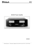
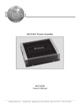
Power Amplifier MCC406M Owner’s Manual McIntosh Laboratory, Inc. 2 Chambers Street Binghamton, New York 13903-2699 Phone: 607-723-3512 FAX: 607-724-0549 The lightning flash with arrowhead, within an equilateral triangle, is intended to alert the user to the presence of uninsulated “dangerous voltage” within the product’s enclosure that may be of sufficient magnitude to constitute a risk of electric shock to persons. WARNING - TO REDUCE RISK OF FIRE OR ELECTRICAL SHOCK, DO NOT EXPOSE THIS EQUIPMENT TO RAIN OR MOISTURE. The exclamation point within an equilateral triangle is intended to alert the user to the presence of important operating and maintenance (servicing) instructions in the literature accompanying the appliance. NO USER-SERVICEABLE PARTS INSIDE. REFER SERVICING TO QUALIFIED PERSONNEL. To prevent the risk of electric shock, do not remove cover or back. No user serviceable parts inside. IMPORTANT SAFETY INSTRUCTIONS! PLEASE READ THEM BEFORE OPERATING THIS EQUIPMENT. 1. Read these instructions. 2. Keep these instructions. 3. Heed all warnings. 4. Follow all instructions. 5. Do not use this apparatus near water. 6. Clean only with a dry cloth. 7. Do not block any ventilation openings. Install in accordance with the manufacturer’s instructions. 8. Do not install near any heat sources such as radiators, heat ducts, or other apparatus (including amplifiers) that produce heat. 9. Warning: This unit is capable of producing high sound pressure levels. Continued exposure to high sound pressure levels can cause permanent hearing impairment or loss. User caution is advised and ear protection is recommended when playing at high volumes. 10. Route DC power cords so that they are not likely to be pinched by items placed upon or against them, paying particular attention to the point where they enter the apparatus. 2 11. Only use attachments/accessories specified by the manufacturer. 12. Do not mount this product with an unstable bracket as the apparatus may fall, causing serious injury to a person, and serious damage to the product. 13. Unplug this apparatus when unused for long periods of time. 14. Refer all servicing to qualified service personnel. Servicing is required when the apparatus has been damaged in any way, such as power-supply cable is damaged, liquid has been spilled or objects have fallen into the apparatus, the apparatus has been exposed to rain or moisture, does not operate normally, or has been dropped. 15. Do not expose this equipment to dripping or splashing and ensure that no objects filled with liquids, such as vases, are placed on the apparatus. Thank You Table of Contents Your decision to own this McIntosh MCC406M Six Channel Power Amplifier ranks you at the very top among discriminating music listeners. You now have “The Best.” The McIntosh dedication to “Quality,” is assurance that you will receive many years of musical enjoyment from this unit. Please take a short time to read the information in this manual. We want you to be as familiar as possible with all the features and functions of your new McIntosh. Safety Instructions ............................................................. 2 Thank You .......................................................................... 3 Please Take a Moment ....................................................... 3 Customer Service ............................................................... 3 Table of Contents ............................................................... 3 Important Information ....................................................... 4 Introduction ....................................................................... 4 Performance Features ........................................................ 4 Dimensions ....................................................................... 5 Installation ........................................................................ 6 Side Panel Cooling and Connections ................................ 7 How to Connect for Six Channels ..................................... 8 How to Connect for Five Channels ................................. 10 How to Connect for Four Channels ................................. 11 How to Connect for Three Channels ............................... 12 Top Panel Controls, Displays and Switches .................... 14 How to Operate the MCC406M ...................................... 15 How to Operate in Six or Five Channel Mode ................ 16 How to Operate in Four or Three Channel Mode ............ 17 How to Replace the Fuses ............................................... 18 Block Diagram ................................................................. 19 Specifications .................................................................. 22 Packing Instructions ........................................................ 23 Please Take A Moment The serial number, purchase date and McIntosh Dealer name are important to you for possible insurance claim or future service. The spaces below have been provided for you to record that information: Serial Number: Purchase Date: Dealer Name: Technical Assistance If at any time you have questions about your McIntosh product, contact your McIntosh Dealer who is familiar with your McIntosh equipment and any other brands that may be part of your system. If you or your Dealer wish additional help concerning a suspected problem, you can receive technical assistance for all McIntosh products at: McIntosh Laboratory, Inc. 2 Chambers Street Binghamton, New York 13903 Phone: 607-723-1545 Fax: 607-723-3636 Customer Service If it is determined that your McIntosh product is in need of repair, you can return it to your Dealer. You can also return it to the McIntosh Laboratory Service Department. For assistance on factory repair return procedure, contact the McIntosh Service Department at: McIntosh Laboratory, Inc. 2 Chambers Street Binghamton, New York 13903 Phone: 607-723-3515 Fax: 607-723-1917 Copyright 2003 by McIntosh Laboratory, Inc. 3 Important Information 1. An optional McIntosh External Subwoofer Rotary Control, Model Number R1163, is available from your McIntosh Dealer. 2. Do not connect the Amplifier Speaker Negative Terminal Connection directly to the Vehicle Chassis. Failure to observe this could result in damage to your Amplifier. 3. For additional connection information, refer to the owner’s manual(s) for any component(s) connected to the MCC406M Amplifier. 4. There is a built-in turn on delay which will mute the speaker outputs for approximately two seconds when the amplifier is turned on. 5. It is very important that loudspeaker cables of adequate size be used in your music system, to ensure that there will be no power loss or heating. If your loudspeaker cables are 25 feet (7.62m) or less, use at least 16 Gauge wire size or larger. 6. It is advisable to place an in(-) NEGATIVE SPEAKER OUTPUT line fuse as close as possible to the battery. 7. The MCC406M can accept speaker level inputs at its Input Jacks. Refer to the (+) POSITIVE SPEAKER OUTPUT diagram for connection. Introduction Now you can take advantage of traditional McIntosh standards of excellence in the MCC406M Power Amplifier. The MCC406M has 400 watts of combined power output with high current capability from six, five, four or three channels and will drive any high quality Loudspeaker System to its ultimate performance. The MCC406M reproduction is sonically transparent and absolutely accurate. The McIntosh Sound is “The Sound of the Music Itself.” Performance Features • Power Output The MCC406M consists of six separate power amplifier channels, with four channels each capable of 50 watts and two channels each capable of 100 watts with less than 0.005% distortion. • Six Bridgeable Channels The MCC406M includes four 50 watt amplifier channels. Each pair of channels can be set in bridged configuration for 200 watts output into a 4 ohm Loudspeaker. The two 100 watt channels may also be bridged for 400 watts output into a 4 ohm Loudspeaker. 4 • High Current Output A peak output current of 20 amperes ensures that the MCC406M will successfully drive high quality Loudspeakers, such as McIntosh, for a truly exciting sound experience. • Variable Crossover Filters The 12dB per octave high pass filters have variable corner frequencies from 5Hz to 5,000Hz and 12dB per octave low pass filters with variable corner frequencies from 50Hz to 5,000Hz. • Illuminated Watt Meters The MCC406M has Output Watt Meters that display the combined output in watts for all six channels. The meters respond 95% full scale to a single cycle tone burst at 2kHz. It is almost ten times faster than a professional VU meter. • Power Guard and Sentry Monitor All channels include the patented McIntosh Power Guard circuit that prevents the amplifier from being overdriven into clipping with its harsh distorted sound that can also damage your valuable Loudspeakers. McIntosh Sentry Monitor power output stage protection circuits are present on all channels to ensure the MCC406M will have a long and trouble free operating life. • Speaker Protection If for any reason, a DC (Direct Current) voltage appears at the speaker output terminals, a built-in circuit turns off the amplifier power supplies to prevent damage to your valuable Loudspeakers. • Thermal Protection with Multi-Speed Cooling Fans Built-in thermal protection circuits guard against overheating which could shorten the normal long life expectancy of your McIntosh Power Amplifier. Cooling fan speed is controlled by temperature sensors attached to the interior of the extruded aluminum cooling tunnel. The fans normally run at a quiet low speed, when needed the fans will automatically switch to a higher speed for increased cooling. • Subwoofer Output Remote Control An optional Subwoofer Remote Control Accessory may be connected to the MCC406M and allows varying the Subwooofer output level. Dimensions Dimensions The following dimensions can assist in determining the best location for your MCC406M. There is additional information on the next page pertaining to installing the MCC406M into your vehicle. Top View of the MCC406M 18-3/8" 46.66cm 15-3/16" 38.57cm 9-3/16" 3-3/16" 23.33cm 8.09cm 12-1/4" 31.12cm 11-13/16" 29.97cm Side View of the MCC406M 11" 27.93cm 11/32" 10.93cm 2-15/16" 7.49cm 5 Installation Installation It is recommended that a professional who is skilled in all aspects of installation and operation install the MCC406M and any associated mobile audio equipment. Amplifier Ventilation Always provide adequate ventilation for the MCC406M. The amplifier requires an adequate airflow into the cooling fans, which are located on the left side of the amplifier. The warm air exits the amplifier through vents on the heatsinks. See figure 1. Be sure to provide at least 1-1/2 inches clearance in front of the cooling fans and 1 inch clearance at the sides of the heatsinks. The cooling fans are controlled by temperature sensors, attached to the interior of the tunnel. The fans are normally off. If the program material contains sustained loud passages demanding high power, the fans will turn-on to increase cooling. If cooling is still not sufficient, additional heating will shut down the amplifier internal power supply completely and the Power Guard LEDs will light. The fans will continue to run and once normal temperatures are restored, operation will resume. The amplifier can be mounted vertically or horizontally and may be located under a seat if adequate clearance is available. The preferred installation method is to mount the amplifier directly to the vehicle main frame using the hardware supplied with the amplifier. It is not recommended that the amplifier be mounted under the hood or in a location where it will be directly exposed to the elements. The openings in the fan housings and heat tunnel vents can allow internal components to be damaged by exposure to water, chemicals or any form of road dust or debris. Warm Air Cool Air Figure 1 Cool Air Warm Air Remove Top Cover Screws Figure 2 Remove Top Cover Screws Remove End Cap Screws Removing the Glass Panel To access the MCC406M Controls, remove the glass panel by removing the four hex bolts with the supplied 3/32” hex key. See figure 2. Attach the supplied suction cup to the top center of the glass panel and carefully raise it high enough to put your hand under. Temporarily place the removed glass panel in a safe place, remove the suction cup and save it for future use. Removing the End Caps To access the MCC406M Connecting Terminal Blocks, remove the Glass Panel first (the above step) and then remove the Phillips Screws holding the End Caps on both sides of the amplifier and lift the end caps off. See figure 3. 6 Figure 3 Remove End Cap Screws Side Panel Cooling and Connections Connect to the Negative (-) vehicle battery terminal Connect to the positve (+) vehicle battery terminal with an inline fuse Cooling Fan Air Intake INPUTs for audio cables from a signal source Cooling Fan Air Intake Receives the Amplifier Turn-ON signal from a McIntosh Control Center OUTPUT Connections for 2, 4 or 8 ohm loudspeakers Connector for optional Subwoofer Remote Volume Control OUTPUT Connections for 2, 4 or 8 ohm loudspeakers Controls the Power Guard Circuit when connected to certain McIntosh Control Centers 7 How to Connect for Six Channels 1. Connect a cable from the Control Center Amp On to the MCC406M ON Connector on the right side of the amplifier. Note: All cables should be connected to the amplifier before connecting the DC power cables to the battery. 2. Connect a cable from a McIntosh Control Center with Power Guard to the MCC406M PG Connector on the right side of the amplifier. 3. Connect cables (up to 12 AWG) from six separate Loudspeaker Drivers to the MCC406M Power Amplifier Channels 1, 2, 3, 4, 5 and 6 Terminals, being careful to observe the correct polarities. 4. Connect a cable (up to 12 AWG) from the Subwoofer Loudspeaker Driver to the McIntosh Mono Power Amplifier Output Terminals, being careful to observe the correct polarities. 5. Connect audio cables from the Control Center Front Outputs to the McIntosh Electronic Crossover Inputs 1 and 2. 6. Connect audio cables from the McIntosh Electronic Crossover Low, Mid and High Outputs 1 and 2 to the MCC406M Power Amplifier Inputs 1, 2, 3, 4, 5 and 6. 7. Connect an audio cable from the McIntosh Electronic Crossover Sub Output to the McIntosh Mono Power Amplifier Input. 8. Connect the MCC406M to the vehicle battery terminals using size 4 AWG (Maximum) cables. Note: It is advisable to place an in-line fuse of a suitable size as close as possible to the battery. McIntosh Electronic Crossover Left Front Output Power Guard Amp ON Right Front Output - Vehicle + Battery 8 Fuse How to Connect for Six Channels McIntosh Mono Power Amplifier (+) Subwoofer (-) (-) (+) (-) (+) (+) (-) (+) Right Front Tweeter Right Front Midrange (-) Right Front Woofer (-) (+) (+) Left Front Tweeter Left Front Midrange (-) Left Front Woofer 9 How to Connect for Five Channels How to Connect for Five Channels 1. Connect a cable from the Control Center Amp On to the MCC406M ON Connector on the right side of the amplifier. Note: All cables should be connected to the amplifier before connecting the DC power cables to the battery. 2. Connect a cable from a McIntosh Control Center with Power Guard to the MCC406M PG Connector on the right side of the amplifier. 3. Connect cables (up to 12 AWG) from four separate Loudspeaker Systems to the MCC406M Power Amplifier Channels 1, 2, 3, and 4 being careful to observe the correct polarities. 4. Connect cables (up to 12 AWG) from the Subwoofer Loudspeaker Drivers to the MCC406M Power Ampli- fier Channels 5 and 6 BRIDGED connection being careful to observe the correct polarities. 5. Connect audio cables from the McIntosh Control Center Front and Rear Outputs to the MCC406M Power Amplifier Inputs 1, 2, 3, and 4. 6. Connect the optional McIntosh external Subwoofer Remote Volume Control to the SUB REMOTE CONTROL Jack on the right side of the MCC406M Power Amplifier. 7. Connect the MCC406M to the vehicle battery terminals using size 4 AWG (Maximum) cables. Note: It is advisable to place an in-line fuse of a suitable size as close as possible to the battery. Left Rear Output Right Rear Output Power Guard Amp ON Left Front Output Right Front Output McIntosh External Subwoofer Rotary Control Left Front Loudspeaker System Right Front Loudspeaker System Left Rear Loudspeaker System (+) Right Rear Loudspeaker System - Vehicle + Battery Fuse (-) Subwoofer 10 How to Connect for Four Channels How to Connect for Four Channels 1. Connect a cable from the Control Center Amp On to the MCC406M ON Connector on the right side of the amplifier. fier Channels 5 and 6 Outputs being careful to observe the correct polarities. 5. Connect audio cables from the McIntosh Control Center Front and Rear Outputs to the MCC406M Power Amplifier Inputs 1, 2, 3 and 4. Note: All cables should be connected to the amplifier before connecting the DC power cables to the battery. Note: The Subwoofer Output Level can be remotely controlled by the optional McIntosh External Subwoofer Rotary Control connected to the SUB REMOTE CONTROL jack on the MCC406M. 2. Connect a cable from a McIntosh Control Center with Power Guard to the MCC406M PG Connector on the right side of the amplifier. 3. Connect cables (up to 12 AWG) from two separate Loudspeaker Systems to the MCC406M Power Amplifier Channels 1 and 2 BRIDGED; 3, and 4 BRIDGED connections being careful to observe the correct polarities. 4. Connect cables (up to 12 AWG) from the Subwoofer Loudspeaker Drivers to the MCC406M Power Ampli- 6. Connect the MCC406M to the vehicle battery terminals using size 4 AWG (Maximum) cables. Note: It is advisable to place an in-line fuse of a suitable size as close as possible to the battery. Optional connections for controlling the Subwoofer Level by using the Front to Rear Fader Control on the Control Center Left Rear Output (Subwoofer Level) Right Rear Output Subwoofer (+) Power Guard Amp ON Optional McIntosh External Subwoofer Rotary Control Left Front Output Right Loudspeaker System Right Front Output (-) Left Loudspeaker System (+) - Vehicle + Battery Fuse (-) Subwoofer 11 How to Connect for Three Channels 1. Connect a cable from the Control Center Amp On to the MCC406M ON Connector on the right side of the amplifier. Note: All cables should be connected to the amplifier before connecting the DC power cables to the battery. 2. Connect a cable from a McIntosh Control Center with Power Guard to the MCC406M PG Connector on the right side of the amplifier. 3. Connect cables (up to 12 AWG) from a Loudspeaker System to the MCC406M Power Amplifier Channels 1 and 2 BRIDGED connections. In a similar manner connect another Loudspeaker system to the 3 and 4 BRIDGED connections, being careful to observe the correct polarities for all connections. 4. Connect cables (up to 12 AWG) from the Subwoofer Loudspeaker Drivers to the MCC406M Power Amplifier Channels 5 and 6 BRIDGED connection being careful to observe the correct polarities. 5. Connect audio cables from the McIntosh Control Center Front Outputs to the McIntosh Custom Environmental Equalizer Inputs 1 and 2. 6. Connect audio cables from the McIntosh Custom Environmental Equalizer Outputs 1 and 2 to the MCC406M Power Amplifier Inputs 1 and 3. 7. Connect the optional McIntosh external Subwoofer Remote Volume Control to the SUB REMOTE CONTROL Jack on the MCC406M Power Amplifier. 8. Connect the MCC406M to the vehicle battery terminals using size 4 AWG (Maximum) cables. Note: It is advisable to place an in-line fuse of a suitable size as close as possible to the battery. (+) Power Guard McIntosh External Subwoofer Rotary Control Amp ON Right Front Output Left Front Output McIntosh Custom Environmental Equalizer - Vehicle + Battery Fuse (-) 12 How to Connect for Three Channels Right Loudspeaker System Left Loudspeaker System Subwoofer 13 Top Panel Controls, Display and Switches CH 5-6 SENSITIVITY Individual Input Sensitivity Controls for Channels 5 and 6 CH 5-6 LOW PASS Filter Switch and Control select the high frequency roll-off or flat frequency response CH 5-6 MODE Switch selects STEREO or BRIDGED mode of operation CH 5-6 HIGH PASS Filter Switch and Control select the low frequency roll-off or flat frequency response POWER GUARD LED lights when the Power Guard Circuit activates for Amplifier Channels 5 or 6 INPUT SOURCE Switch for Channels 5-6 selects either CHs 5 and 6, 1 and 2 or Subwoofer (Sum of CHs 1, 2, 3, and 4) POWER GUARD LED lights when the Power Guard Circuit activates for Amplifier Channels 1 thru 4 METER indicates Channels 1 thru 4 Power Output CH 1-2 MODE Switch selects STEREO or BRIDGED mode of operation CH 1-2 HIGH PASS Filter Switch and Control select the low frequency roll-off or flat frequency response 14 METER indicates Channels 5 and 6 Power Output CH 3-4 MODE Switch selects STEREO or BRIDGED mode of operation CH 3-4 LOW PASS Filter Switch and Control select the high frequency roll-off or flat frequency response CH 3-4 HIGH PASS Filter Switch and Control select the low frequency roll-off or flat frequency response INPUT SOURCE Switch for Channels 3-4 selects either CHs 3 and 4 or 1 and 2 CH 1-4 SENSITIVITY Individual Input Sensitivity Controls for Channels 1, 2, 3 and 4 How to Operate the MCC406M Introduction The McIntosh MCC406M is a highly versatile amplifier that can be configured in many ways. This manual gives examples of some of the most common configurations. The best way to set the filter controls is through the use of a real-time spectrum analyzer and the expertise of a professional installer. This manual will guide you through the basic operation, however we suggest you refer to your Dealer for further information on the use of this unit. To access the Amplifier Controls and Switches refer to “Removing the Glass Panel” located on page 6 of this Owner’s Manual. Low Pass Filter The LOW PASS Filter Controls select the frequencies at which the filters operate. Any given frequency number is selected through the combined settings of the FREQUENCY and MULTIPLIER controls. The low-pass filters multiplier switches have settings of X1 (frequency times one), X10 (frequency times ten). Refer to figure 4. owner’s manual. The Level controls can be set for any sensitivity from .5 volts to 8 volts. Refer to figure 6. Note: When used in conjunction with a McIntosh control center, you may find setting the Sensitivity controls to the center detent (1.5V) works best. Figure 6 Power Output Meters There are two illuminated watt meters on the glass panel, the left meter displaying combined power output for channels 1, 2, 3 and 4 and the right meter displaying combined power output for channels 5 and 6. The upper scale shows power in watts during normal operation, the lower scale displays power in watts for bridged operation. All displays show power into a 4 ohm load. The meters respond to all the musical information being produced by the amplifier. Figure 4 Example: A frequency 1,500 Hz would be attained by setting the FREQUENCY Control to 150 and setting the MULTIPLIER Switch to X10 (150 times 10 equals 1,500). High Pass Filter The HIGH PASS Filter Controls select the center frequencies at which the filters operate. Any given frequency number is selected through the combined settings of the FREQUENCY and MULTIPLIER controls. The high-pass filter multiplier switches have settings of X.1 (frequency times one-tenth), X1 (frequency times one), X10 (frequency times ten). Refer to figFigure 5 ure 5. Example: A frequency of 15 Hz would be selected by setting the FREQUENCY Control to 150 and the MULTIPLIER Switch to X.1 (150 times .1 equals 15). Figure 7 They indicate to an accuracy of at least 95% of the power output with only a single cycle of a 2000Hz tone burst. Refer to figure 7. Power The MCC406M will turn on or off when the Control Center turns On or Off. Note: There must be an Amp ON connection between the MCC406M and the signal source unit in order for the amplifier power turn On and Off to function. Input Sensitivity Controls The SENSITIVITY controls allow independent setting of the input sensitivity of all amplifier channels, to provide an ideal match for the signal source being used. The most desirable setting allows the control center to have a useful volume range as wide as possible from loud to soft. A good place to start is to set the amplifier’s SENSITIVITY Control to the output voltage called out in your control center 15 How to Operate in Six or Five Channel Mode How to Operate in Six Channel Mode How to Operate in Five Channel Mode In the 6 Channel Operating Mode, channels 1 thru 4 operate as independent 50 watt amplifiers; channels 5 and 6 each provide 100 watts of power output. A typical six channel application is to use an Electronic Crossover Network ahead of the MCC406M Power Amplifier and each amplifier channel powers Loudspeaker Drivers directly. A second power amplifier is used to drive the Subwoofer. Refer to figures 8 and 9, along with pages 8 and 9 of this Owner’s Manual. In the 5 Channel Operating Mode, channels 1 thru 4 operate as independent 50 watt amplifiers for the front and rear Loudspeakers; channels 5 and 6 are Bridged for 400 watts of power output. Refer to figures 8 and 9, along with page 10 of this Owner’s Manual. Input Source Set the Channel 3-4 INPUT SOURCE Switch to 3, 4 and the Channel 5-6 INPUT SOURCE Switch to the 5-6 position for 6 Channel Mode. Sensitivity Controls The Sensitivity Controls allow setting of the input level of all six amplifier channels to provide an ideal match for the signal source being used. Output Mode Set all three OUTPUT MODE Switches to the STEREO position to configure the amplifier for six channel operation. High Pass Filter Set each of the High Pass Filter Frequency Controls to 50 and the MULTIPLIER Switches to X.1. This will pass the full audible spectrum, yet filter out power-robbing subsonics below 5 Hz. Low Pass Filter Set each of the Low Pass Filter Switches to the OUT position. Input Source Set the Channel 3-4 INPUT SOURCE Switch to 3, 4 and the Channel 5-6 INPUT SOURCE Switch to the 1-4 (SUB) position for 5 Channel Mode. Sensitivity Controls The Sensitivity Controls allow setting of the input level of all five amplifier channels to provide an ideal match for the signal source being used. Note: Set CH6 SENSITIVITY Control to the maximum counterclockwise position. Output Mode Set CHANNELS 1-2 and 3-4 OUTPUT MODE Switches to the STEREO position. Set the CHANNELS 5-6 OUTPUT MODE Switch to the BRIDGED position. This will configure the amplifier for five channel operation. High Pass Filter Set the Channels 1-2 and 3-4 High Pass Filters’ FREQUENCY Control to 100 and the MULTIPLIER Switch to X1. Set the channel 5-6 High Pass Filter Frequency Control to 50 and the MULTIPLIER Switch to X.1. This will send frequencies above 100Hz to the upper range speakers for channels 1 thru 4 and roll-off frequencies below 5Hz for channels 5-6. Low Pass Filter Set the Channel 3-4 low pass filter to OUT. Set the Channel 5-6 Low Pass Filter FREQUENCY Control to 100 and the MULTIPLIER Switch to X1. This will roll-off frequencies above 100Hz for channels 5-6. Figure 8 16 How to Operate in Four or Three Channel Mode How to Operate in Four Channel Mode How to Operate in Three Channel Mode In the 4 Channel Operating Mode channel pairs of (1 and 2) and (3 and 4) are bridged to provide 200 watts each. Channels 5 and 6 are driven independently for 100 watts output for each channel. Refer to figures 8 and 9, along with page 11 of this Owner’s Manual. In the 3 Channel Operating Mode channel pairs of (1 and 2), (3 and 4) and (5-6) are bridged. This configuration provides two 200 watt channel amplifiers and one 400 watt amplifier. Refer to figures 8 and 9, along with pages 12 and 13 of this Owner’s Manual. Input Source Set the Channel 3-4 INPUT SOURCE Switch to the 3, 4 and the Channel 5-6 INPUT SOURCE Switch to the 5, 6 position for 4 Channel Mode. Input Source Set the Channel 3-4 INPUT SOURCE Switch to the 3, 4 and the Channel 5-6 INPUT SOURCE Switch to the 1-4 (SUB) position. Sensitivity Controls The Sensitivity Controls (1, 3, 5 and 6) allow setting the input level of the amplifier channels to provide an ideal match for the signal source being used. Sensitivity Controls The Sensitivity Controls allow setting the input level of amplifier channels 1 and 3 to provide an ideal match for the signal source being used. Sensitivity Control 5 adjusts the woofer level balance. Note: Set CH2 and CH4 SENSITIVITY Controls to the maximum counterclockwise position. Note: Set CH2, CH4 and CH6 SENSITIVITY Controls to the maximum counterclockwise position. Output Mode Set CHANNELS 1-2 and 3-4 OUTPUT MODE Switches to the BRIDGED position. Set CHANNELS 5-6 OUTPUT MODE Switch to the STEREO position. This will configure the amplifier for four channel operation. High Pass Filter Set the Channels 1-2 and 3-4 High Pass Filters’ FREQUENCY Control to 100 and the MULTIPLIER Switch to X1. Set the channel 5-6 High Pass Filter Frequency Control to 50 and the MULTIPLIER Switch to X.1. This will send frequencies above 100Hz to the upper range speakers for channels 1 thru 4 and roll-off frequencies below 5Hz for channels 5-6. Low Pass Filter Set the Channel 3-4 low pass filter to OUT. Set the Channel 5-6 Low Pass Filter FREQUENCY Control to 100 and the MULTIPLIER Switch to X1. This will roll-off frequencies above 100Hz for channels 5-6. Output Mode Set all three OUTPUT MODE Switches to the BRIDGED position. High Pass Filter Set the Channels 1-2 and 3-4 High Pass Filters’ FREQUENCY Control to 100 and the MULTIPLIER Switch to X1. Set the channel 5-6 High Pass Filter Frequency Control to 50 and the MULTIPLIER Switch to X.1. This will send frequencies above 100Hz to the upper range speakers for channels 1 thru 4 and roll-off frequencies below 5Hz for channels 5-6. Low Pass Filter Set the Channel 3-4 low pass filter to OUT. Set the Channel 5-6 Low Pass Filter FREQUENCY Control to 100 and the MULTIPLIER Switch to X1. This will roll-off frequencies above 100Hz for channels 5-6. Figure 9 17 How to Replace the Fuses How to Replace the Fuses If the MCC406M produces no sound, there is no Illumination of the Nomenclature on the Top Glass Panel, and the power connections seem secure, one or more of the Amplifier Fuse(s) may have failed. Under normal operating conditions your amplifier’s fuses should not fail. Failure of a fuse is usually an indication of a problem. Replacing the fuse, if there is problem in the amplifier, may incur a risk of further damage. Refer to figures 10, 11 and 12. Remove Top Cover Screws Figure 10 Caution: Disconnect the Amplifier from the Vehicle Battery ( or DC Power Supply) as Potentially Dangerous Currents exist inside the amplifier. 1. Before accessing fuses, disconnect both the positive and negative power cables from the DC input terminals on the left side of the amplifier using a 5/32” hex key. 2. Remove the Top Glass Panel by first removing the four hex bolts with the supplied 3/32” hex key. 3. To remove the Top Glass Panel, attach the supplied suction cup to the top center of the glass panel and carefully raise it high enough to put your hand under. Temporarily place the removed glass panel in a safe place, remove the suction cup and save it for future use. 4. Remove the Phillips Screws holding the End Caps on both sides of the amplifier and lift the end caps off. 5. Remove the two Phillips screws located between the low and high pass filter controls. 6. Remove all 12 crossover, equalizer and sensitivity knobs. 7. Remove the Gold Faceplate Control Panel. 8. Remove the fuses with needle nose pliers, taking care to avoid hitting the wattmeter during removal. Do not lever the pliers against the wattmeter. Remove Top Cover Screws Remove Three Screws Figure 11 Remove Three Screws Location of the four fuses Note: To determine if the fuse has failed, examine the link between the two fuse legs to see if it has a break in it. 9. Replace the fuse with one of the same type and rating as unauthorized substitutions may prove hazardous to you and the amplifier. 10. When reinserting the fuse, set it in place with the pliers, then push it the rest of the way in with your finger to avoid having the pliers slip and hit the circuit board. 11. Re-install the Gold Faceplate Control Panel and all 12 crossover, equalizer and sensitivity knobs. 12. Re-connect the power cables to the vehicle battery. If the replacement fuse(s) fails again, have the amplifier repaired at a McIntosh Service Center. 18 Figure 12 MCC406M Block Diagram MCC406M Block Diagram 19 20 Notes 21 Specifications Specifications Power Output Per Channel Channels 1 thru 4: 50 watts into 4 ohm loads or 100 watts into 2 ohm loads, is the minimum sine wave continuous average power output per channel all channels operating. Channels 5 and 6: 100 watts into 4 ohm loads or 200 watts into 2 ohm loads, is the minimum sine wave continuous average power output per channel all channels operating. Power Output Bridged Channels (1 and 2) or (3 and 4): 200 watts into 4 ohm loads, is the minimum sine wave continuous average power output with all channels operating. Channels (5 and 6): 400 watts into 4 ohm loads is the minimum sine wave continuous average power output with all channels operating. Rated Power Band 20Hz to 20,000Hz Total Harmonic Distortion Maximum Total Harmonic Distortion at any power level from 250 milliwatts to rated power output is: 0.005% for 4 ohm loads 0.01% for 2 ohm loads 0.01% for Bridged Mode with 4 ohm loads Dynamic Headroom 1dB Frequency Response +0, -0.25dB from 20Hz to 20,000Hz +0, -3dB from 10Hz to 50,000Hz Sensitivity 0.5Volts A-Weighted Signal To Noise Ratio 105dB (1.5V) High Pass Filter Variable from 5Hz to 5,000Hz, 12 dB per octave Low Pass Filter Variable from 50Hz to 5,000Hz, 12 dB per octave (24 dB per octave in Bridged Mode for Channels 5 and 6) 22 Subwoofer Filter Low Pass filtered at 200 Hz with a 6dB per octave slope (level variable ±12dB when using optional McIntosh External Subwoofer Rotary Control). Intermodulation Distortion Maximum Intermodulation Distortion if instantaneous peak output per channel does not exceed twice the rated output, for any combination of frequencies from 20Hz to 20,000Hz, with all channels operating is: 0.005% for 4 ohm loads 0.01% for 2 ohm loads 0.01% for Bridged Mode with 4 ohm loads Input Impedance 12,000 ohms Power Requirements 12 Volts DC, 4.5 amps (idle) - 75 amps (4 ohm loads) Dimensions 12-1/2 inches (31.1 cm) wide, 3 inches (7.6 cm) high, 18-2/5 inches (46.7cm) depth Weight 20.5 pounds (9.3 Kg) net, 23.5 pounds (10.6 Kg) in shipping carton Packing Instructions Packing Instructions In the event it is necessary to repack the equipment for shipment, the equipment must be packed exactly as shown below, failure to do so will result in shipping damage. Make sure that the Top Glass Panel is firmly secured to the chassis using the supplied hex head screws. Use the original shipping carton and interior parts only if they are all in good serviceable condition. If a shipping carton or any of the interior part(s) are needed, please call or write Customer Service Department of McIntosh Laboratory. Please see the Part List for the correct part numbers. Quantity 1 2 Part Number 033775 034132 Description Shipping carton only End cap (Foam pad) 23 McIntosh Laboratory, Inc. 2 Chambers Street Binghamton, NY 13903 The continuous improvement of its products is the policy of McIntosh Laboratory Incorporated who reserve the right to improve design without notice. Printed in the U.S.A. McIntosh Part No. 040842