1
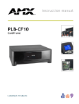
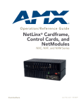
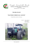
instruction manual
PLB-CF2
Two-Slot Mini Cardframe
L a n d m a r k P r o d u c ts
AMX Limited Warranty and Disclaimer
AMX Corporation warrants its products to be free of defects in material and workmanship under normal use for
three (3) years from the date of purchase from AMX Corporation, with the following exceptions:
•
Electroluminescent and LCD Control Panels are warranted for three (3) years, except for the display and touch
overlay components that are warranted for a period of one (1) year.
•
Disk drive mechanisms, pan/tilt heads, power supplies, MX Series products, and KC Series products are
warranted for a period of one (1) year.
•
Unless otherwise specified, OEM and custom products are warranted for a period of one (1) year.
•
Software is warranted for a period of ninety (90) days.
•
Batteries and incandescent lamps are not covered under the warranty.
This warranty extends only to products purchased directly from AMX Corporation or an Authorized AMX Dealer.
AMX Corporation is not liable for any damages caused by its products or for the failure of its products to perform.
This includes any lost profits, lost savings, incidental damages, or consequential damages. AMX Corporation is not
liable for any claim made by a third party or by an AMX Dealer for a third party.
This limitation of liability applies whether damages are sought, or a claim is made, under this warranty or as a tort
claim (including negligence and strict product liability), a contract claim, or any other claim. This limitation of
liability cannot be waived or amended by any person. This limitation of liability will be effective even if AMX
Corporation or an authorized representative of AMX Corporation has been advised of the possibility of any such
damages. This limitation of liability, however, will not apply to claims for personal injury.
Some states do not allow a limitation of how long an implied warranty last. Some states do not allow the limitation or
exclusion of incidental or consequential damages for consumer products. In such states, the limitation or exclusion of
the Limited Warranty may not apply. This Limited Warranty gives the owner specific legal rights. The owner may
also have other rights that vary from state to state. The owner is advised to consult applicable state laws for full
determination of rights.
EXCEPT AS EXPRESSLY SET FORTH IN THIS WARRANTY, AMX CORPORATION MAKES NO
OTHER WARRANTIES, EXPRESSED OR IMPLIED, INCLUDING ANY IMPLIED WARRANTIES OF
MERCHANTABILITY OR FITNESS FOR A PARTICULAR PURPOSE. AMX CORPORATION
EXPRESSLY DISCLAIMS ALL WARRANTIES NOT STATED IN THIS LIMITED WARRANTY. ANY
IMPLIED WARRANTIES THAT MAY BE IMPOSED BY LAW ARE LIMITED TO THE TERMS OF THIS
LIMITED WARRANTY.
Table of Contents
Product Information...............................................................1
Overview
1
Safety Instructions
3
Operation Instructions ...........................................................5
Power-Up Procedure
5
PhastLink Ports
5
MCU-to-PC Connection
5
Device Address
5
PhastLink Cable Information
6
Connecting to a Cardframe or Hub
7
Building a double 120-ohm terminator:
8
Troubleshooting...................................................................11
PLB-CF2 Two-Slot Mini Cardframe
Table of Contents
i
ii
Table of Contents
PLB-CF2 Two-Slot Mini Cardframe
Product Information
Overview
The PLB-CF2 Mini Cardframe can accommodate either one or two PHAST control
cards. Any PHAST control card can be installed in the PLB-CF2.
If a PHAST PLC-MCU board is installed in a PLB-CF2, it can control a small
Landmark system without the need for a PHAST PLB-CF10 Cardframe or a PHAST
Hub Box.
More typically, the PLB-CF2 will be used in addition to an existing PLB-CF10
Cardframe to allow one or two PHAST control cards to be placed at any remote
location on a PhastLink network.
A maximum of 20 devices can be attached. The 12 VDC power supply for the PLBCF2 can also power up to two PLK-IMS or PLK-DMS keypads.
The PLB-CF2 is housed in an elegant black enclosure that is in harmony with the
design of other Landmark products. Its small size allows it to be placed in
convenient, unobtrusive locations.
Figure 1 and Figure 2 show the PLB-CF2.
Figure 1
PLB-CF2 (front view)
PLB-CF2 Two-Slot Mini Cardframe
Product Information
1
Figure 2
PLB-CF2 (rear view)
Figure 3 gives product specifications for the PLB-CF2.
Figure 3
PLB-CF2 Specifications
PLB-CF2 Specifications
Card Slots
2 rear-access slots on rear panel
PhastLink Ports
2 RJ-45 ports on rear panel
Cardframe ID
Set via DIP switch on rear panel
Data Indicator
Green LED on rear panel
Diagnostic Indicator
Red LED on rear panel and red LED on front panel
Power Indicator
Red LED on front panel
Power
External 12 VDC, 1-amp power supply
HWD
TBD
Weight
TBD
2
Product Information
PLB-CF2 Two-Slot Mini Cardframe
Safety Instructions
ATTENTION!
Read and follow all safety and operating instructions before installing or operating
this device. Adhere to all warnings listed on the device and in the operating
instructions.
CAUTION
RISK OF ELECTRIC SHOCK
DO NOT OPEN
CAUTION: TO REDUCE THE RISK OF ELECTRIC SHOCK,
DO NOT REMOVE COVER (OR BACK).
NO USER-SERVICEABLE PARTS INSIDE.
REFER SERVICING TO QUALIFIED SERVICE PERSONNEL.
The lightning flash with
arrowhead symbol within an
equilateral triangle is intended
to alert the user to the
presence of uninsulated
"dangerous voltage" within the
product's enclosure that may
be of sufficient magnitude to
constitute a risk of electric
shock to persons.
The exclamation point within
an equilateral triangle is
intended to alert the user to
the presence of important
operating and maintenance
(servicing) instructions in the
literature accompanying the
appliance.
WARNING!
TO REDUCE THE RISK OF FIRE OR ELECTRIC SHOCK, DO NOT EXPOSE
THIS APPLIANCE TO RAIN OR MOISTURE.
1. Slots and openings in the cabinet are provided for ventilation and to ensure
reliable operation of the device. These openings must not be blocked or
covered.
2. Operate this device only from the type of power source indicated by the
product documentation or by a label on the device.
3. To avoid creating a hazardous situation, do not use attachments or accessories
unless approved by the manufacturer. Use only in accordance with the
manufacturer’s instructions.
4. Disconnect this device from the power source before cleaning. Do not use
liquid or aerosol cleaners. Use only a clean, soft, damp cloth for cleaning.
PLB-CF2 Two-Slot Mini Cardframe
Product Information
3
4
Product Information
PLB-CF2 Two-Slot Mini Cardframe
Operation Instructions
Power-Up Procedure
1. Plug the power cord into a properly grounded 110-120VAC outlet.
2. Plug the 12 VDC power supply connector into the 12 VDC receptacle on the
rear panel of the PLB-CF2.
3. The Power LED should be illuminated on the front panel. If there is a problem,
contact your PHAST dealer or PHAST Technical Support.
PhastLink Ports
There are two PhastLink ports on the lower part of the rear panel. These are used to
connect PhastLink devices to the cardframe. If more ports are required, an
additional cardframe or hub box will be necessary. It does not matter which
PhastLink port you use; they are all functionally identical. See the section on
PhastLink Wiring for general information about connecting PhastLink devices.
MCU-to-PC Connection
If a PHAST MCU card is installed, a 10Base-T Ethernet port on the MCU card is
used to connect the to an ethernet board in the PC. See the PHAST PLC-MCU
documentation for more information on connecting and using the MCU card.
Device Address
A DIP switch on the rear panel allows you to set the cardframe address to match its
address in the Landmark software. The following illustration shows the address
settings (factory default is 0):
Figure 4
DIP Switch settings
PLB-CF2 Two-Slot Mini Cardframe
Operation Instructions
5
Warning! Dangerous Voltage!
TO AVOID SERIOUS INJURY OR DEATH, DO NOT OPEN UP THE
CARDFRAME.
PhastLink Cable Information
This section contains information that you will need to make PhastLink cables,
plus general information on connecting PhastLink devices.
PhastLink cables are used to connect all PhastLink-compatible devices, including
keypads, dimmers, amplifiers, audio switches, etc. PhastLink uses a standard
10Base-T connection (i.e. Category 5 wire and RJ-45 connectors). The wire should
be connected in the standard manner, as shown in the following figure. If a
consistent color code is used, wiring problems will be minimized.
Figure 5 shows the RJ-45 Socket and Connector, and Figure 6 gives pinout
information.
Figure 5
RJ-45 Socket
RJ-45 Plug
RJ-45 Socket and Connector
1 2 3 4 5 6 7 8
1 2 3 4 5 6 7 8
6
Operation Instructions
PLB-CF2 Two-Slot Mini Cardframe
Figure 6
RJ-45 Pinout Information
RJ-45 Pinout Information
Pin #
Wire Color
Polarity
Function
1
White/Green
+
Transmit
2
Green
–
Transmit
3
White/Orange
–
Mic
4
Blue
–
Ground
5
White/Blue
+
12VDC
6
Orange
+
Mic
7
White/Brown
+
Receive
8
Brown
–
Receive
PhastLink uses a standard 10Base-T connection (i.e. Category 5 wire and RJ-45
connectors). The wire should be connected in the standard manner, as shown in
the following figure. If a consistent color code is used, wiring problems will be
minimized.
It is important that the correct pairing is observed. Transmit, Receive, and Mic need
to be on twisted pairs. Splitting pairs (e.g., using a white/green wire with a
blue/white wire for transmit) will result in increased crosstalk, and may result in
bus failure or noise on the intercom.
Connecting to a Cardframe or Hub
If a PLB-CF10 cardframe is used, a 15-port hub is built into the cardframe. The
maximum length of wire per port is 1,000 feet. Each PhastLink device has two RJ45 connectors to allow multiple devices to be daisy-chained on one PhastLink port.
Refer to the PLB-CF10 documentation for more detailed connection information.
The limit for each home run is 10 PhastLink devices. Extra hubs can be added to
provide additional ports.
PLB-CF2 Two-Slot Mini Cardframe
Operation Instructions
7
Figure 7
Connecting to a PLB-CLF
cardframe.
Note
Only one PHAST keypad can
be used per port, so homerun each keypad.
For optimum performance, PHAST recommends the installation of a double 120ohm terminator in one of the RJ-45 jacks of the last device (or the only device) in a
chain of PhastLink devices.
Building a double 120-ohm terminator:
1. Install a 120-ohm resistor (1/4-watt or larger) between pins 1 and 2 of an RJ-45
connector.
2. Install a 120-ohm resistor (1/4-watt or larger) between pins 7 and 8 of the same
RJ-45 connector.
PHAST LCD keypads must connect directly to a PHAST Hub (or PHAST
Microphone Hub). Due to power requirements and/or the need for a separate
microphone line for each keypad, they cannot be daisy-chained to other LCD
keypads; they can, however be daisy chained with other PhastLink devices.
8
Operation Instructions
PLB-CF2 Two-Slot Mini Cardframe
When connecting PHAST keypads that will be used as intercoms, the Microphone
Hub taps off the intercom audio signal carried on the PhastLink cable from that
keypad.
PhastLink devices cannot be wired in a star configuration.
PLB-CF2 Two-Slot Mini Cardframe
Operation Instructions
9
10
Operation Instructions
PLB-CF2 Two-Slot Mini Cardframe
Troubleshooting
•
Power LED – If the power LED is not on, check the power cord and power
switch (PLB-CF10) or check the external power supply (PLB-CF2).
•
Diag LED – This LED indicates the state of all cards in the PLB-CF2 or
PLB-CF10. The Diag light will flash on briefly when a card is first plugged
in or powered up. If a card causes an error, the Diag LED will either flash
on and off continually or it will remain on continually. Remove the cards
one by one until you locate the faulty card.
•
Data LED – This LED is a 'window' into the network, flashing on briefly
whenever a packet is sent over the network by the MCU card or by any
device on the PhastLink network.
In normal operation, the Data LED should be off for a larger percentage of
time than it is on.
If the Data LED is on continually, there may be a problem with a hub-tohub connection (e.g., Hub In connected to Hub In, or a bad cable). A looped
cable connecting two PhastLink ports or a faulty cable can also cause the
Data LED to remain on continually. Remove each cable one by one, then
each card one by one until the faulty cable or card is located. If all
PhastLink cables, hub-to-hub cables, and cards are removed and the Data
LED remains on, the PLB-CF2 or PLB-CF10 may be at fault – contact
PHAST Tech Support.
If the Data LED is not on continually but is on for a larger percentage of
time than it is off, it may indicate a faulty device or card, and the condition
may slow down network response.
•
PLB-CF2 Two-Slot Mini Cardframe
Link LED – The Link LED on each card indicates when it sends a message
over the network. If a card's Link LED is on continually, that card may be
causing the problem. For example, this could be caused by a contact card
with an intermittent short or by a faulty contact sensor. If no cards are at
fault, unplug each PhastLink cable run until the suspect cable is located.
Troubleshooting
11
brussels • dallas • los angeles • mexico city • philadelphia • shanghai • singapore • tampa • toronto • york
3000 research drive, richardson, TX 75082 USA • 469.624.8000 • 800.222.0193 • fax 469.624.7153 • technical support 800.932.6993
051-004-2415 8/01 ©2001 AMX Corporation. All rights reserved. AMX, the AMX logo, the building icon, the home icon, and the light bulb icon are all trademarks of AMX Corporation.
AMX reserves the right to alter specifications without notice at any time. *In Canada doing business as Panja Inc.
AMX reserves the right to alter specifications without notice at any time.