1
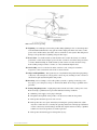
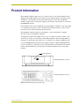
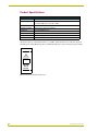
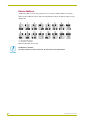
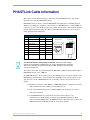
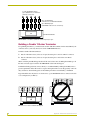
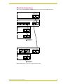
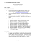
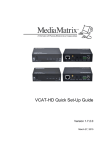
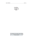
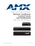
instruction manual
PLB-CF10
CardFrame
Landmark Products
AMX Limited Warranty and Disclaimer
AMX Corporation warrants its products to be free of defects in material and workmanship under normal use for
three (3) years from the date of purchase from AMX Corporation, with the following exceptions:
•
Electroluminescent and LCD Control Panels are warranted for three (3) years, except for the display and touch
overlay components that are warranted for a period of one (1) year.
•
Disk drive mechanisms, pan/tilt heads, power supplies, MX Series products, and KC Series products are
warranted for a period of one (1) year.
•
Unless otherwise specified, OEM and custom products are warranted for a period of one (1) year.
•
Software is warranted for a period of ninety (90) days.
•
Batteries and incandescent lamps are not covered under the warranty.
This warranty extends only to products purchased directly from AMX Corporation or an Authorized AMX Dealer.
AMX Corporation is not liable for any damages caused by its products or for the failure of its products to perform.
This includes any lost profits, lost savings, incidental damages, or consequential damages. AMX Corporation is not
liable for any claim made by a third party or by an AMX Dealer for a third party.
This limitation of liability applies whether damages are sought, or a claim is made, under this warranty or as a tort
claim (including negligence and strict product liability), a contract claim, or any other claim. This limitation of
liability cannot be waived or amended by any person. This limitation of liability will be effective even if AMX
Corporation or an authorized representative of AMX Corporation has been advised of the possibility of any such
damages. This limitation of liability, however, will not apply to claims for personal injury.
Some states do not allow a limitation of how long an implied warranty last. Some states do not allow the limitation or
exclusion of incidental or consequential damages for consumer products. In such states, the limitation or exclusion of
the Limited Warranty may not apply. This Limited Warranty gives the owner specific legal rights. The owner may
also have other rights that vary from state to state. The owner is advised to consult applicable state laws for full
determination of rights.
EXCEPT AS EXPRESSLY SET FORTH IN THIS WARRANTY, AMX CORPORATION MAKES NO
OTHER WARRANTIES, EXPRESSED OR IMPLIED, INCLUDING ANY IMPLIED WARRANTIES OF
MERCHANTABILITY OR FITNESS FOR A PARTICULAR PURPOSE. AMX CORPORATION
EXPRESSLY DISCLAIMS ALL WARRANTIES NOT STATED IN THIS LIMITED WARRANTY. ANY
IMPLIED WARRANTIES THAT MAY BE IMPOSED BY LAW ARE LIMITED TO THE TERMS OF THIS
LIMITED WARRANTY.
Safety Instructions
Safety Instructions
1. Read Instructions - Read all of the safety and operating instructions before operating the
product.
2. Retain Instructions - Retain the safety and operating instructions for future reference.
3. Heed Warnings - Adhere to all warnings on the product and in the operating instructions.
4. Follow Instructions - Follow all operating and use instructions.
5. Cleaning - Unplug this product from the wall outlet or other power source before cleaning. Do
not use liquid or aerosol cleaners. Use only a clean, damp cloth for cleaning.
6. Attachments - Do not use attachments or accessories that are not recommended by the
manufacturer, as they may cause hazards.
7. Water and Moisture - Do not use this product near water, such as a bath tub, wash basin,
kitchen sink, wet basement, swimming pool, or any other water or wet area.
8. Accessories - Do not place this product on an unstable cart, stand, tripod, bracket, table, or
other surface or object. The product may fall, causing serious bodily injury to a child or adult.
It may also cause equipment damage. Use this product only with a cart, stand, tripod, bracket,
table, or other device that is recommended by the manufacturer or sold with the product.
Mount this device only in accordance with the manufacturer's instructions, using only
mounting accessories recommended by the manufacturer.
9. Moving the Product - A product and cart combination must be moved with care. Quick stops,
excessive force, and uneven surfaces may cause the product and cart combination to tip or
overturn.
10. Ventilation - Slots and openings in the cabinet are provided for ventilation and to ensure
reliable operation of the product and to protect if from overheating. These openings must not
PLB-CF10 CardFrame
a
Safety Instructions
be blocked or covered. Never block these openings by placing the product on a bed, sofa, rug,
or similar surface that may cover the openings. Do not install this product in a rack, built-in
installation, such as a bookcase or other enclosure, unless adequate ventilation is provided or
the manufacturer's instructions are adhered to.
11. Power Sources - Operate this product only from the type of power source indicated by the
product documentation or by a marking label on the product. If you are not sure if the power
source in your home or building is correct for the product, consult your product dealer or local
power company. For products intended for operation from battery power or other sources, refer
to the operating instructions.
12. Grounding or Polarization - This product is shipped with a three-wire grounding-type plug, a
plug having a third (grounding) pin. This plug will only fit into a grounding-type power outlet
that is designed for use with this plug. This is a safety feature. If you are unable to insert the
plug into the outlet, contact an electrician to replace the obsolete or incorrect outlet. Do not
defeat the safety purpose of the grounding-type plug.
13. Power Cord Protection - Power supply cords should be routed so that they are not likely to be
walked on or pinched by items placed on or against them. Pay particular attention to cords at
plugs, convenience receptacles, and the point where they exit from the product.
14. Protective Attachment Plug - If the product is equipped with an attachment plug with
overload protection, refer to the manufacturer's instructions for replacement or resetting of this
protective device. If replacement of the plug is required, make sure the service technician has
used a replacement plug specified by the manufacturer that has the same overload protection as
the original plug.
Use the same bonded-ground as the house. Refer to the FIG. 1 on page c for more
information.
15. Outdoor Antenna Grounding - If an outside antenna or cable system is connected to the
product, make sure the antenna or cable system is grounded to provide some protection against
voltage surges and built-up static charges (FIG. 1). Article 810 of the National Electrical Code,
ANSI/NFPA 70, provides information regarding proper grounding of the mast and supporting
structure, grounding of the lead-in wire to the antenna discharge unit, size of grounding
conductors, location of antenna-discharge unit, connection to grounding electrodes, and
requirements for the grounding electrode.
b
PLB-CF10 CardFrame
Safety Instructions
FIG. 1 Outdoor antenna grounding
16. Lightning - For added protection for this product during lightning storms, or when the product
is left unattended and unused for long periods of time, unplug it from the wall outlet or other
power source and disconnect other wires, such as an antenna or cable system. This will prevent
damage to the product due to lightning and power line surges.
17. Power Lines - An outside antenna system should not be located in the vicinity of overhead
power lines or other electrical light or power circuits, or where it can fall into such power lines
or circuits. When installing an outside antenna system, extreme care must be taken to keep
from touching such power lines or circuits, as contact with them might be fatal.
18. Overloading - Do not overload wall outlets, extension cords, or integral convenience
receptacles, as this can result in a risk of fire or electrical shock.
19. Object and Liquid Entry - Never push objects of any kind into this product through openings,
as they may contact dangerous voltage points or short out parts, resulting in a fire or electrical
shock. Never spill any kind of liquid on this product.
20. Servicing - Do not attempt to service this product yourself, as opening or removing covers
may expose you to dangerous voltage or other hazards. Refer all servicing to qualified service
personnel.
21. Damage Requiring Service - Unplug this product from the wall outlet or other power source.
Refer servicing to qualified service personnel under the following conditions:
a. When the power supply cord or plug is damaged.
b. If liquid has been spilled on the product or if objects have fallen into the product.
c. If the product has been exposed to rain or water.
d. If the product does not operate normally by following the operating instructions, adjust
only those controls that are covered by the operating instructions. An improper adjustment
of other controls may result in damage and will often require extensive work by a qualified
technician to restore the product to its normal operation.
e. If the product has been dropped or damaged in any way.
PLB-CF10 CardFrame
c
Safety Instructions
f. When the product exhibits a distinct change in performance. This indicates a need for
service.
22. Replacement Parts - When replacement parts are required, make sure the service technician
has used replacement parts that are specified by the manufacturer or have the same
characteristics as the original parts. Unauthorized substitutions may result in fire, electrical
shock, or other hazard.
23. Safety Check - Upon completion of any service or repairs to this product, ask the service
technician to perform safety checks to determine that the product is in proper operating
condition.
24. Wall or Ceiling Mounting - The product should be mounted to a wall or ceiling only as
recommended by the manufacturer.
25. Heat - The product should be situated away from heat sources, such as radiators, heat registers,
stoves, or other products (including amplifiers) that produce heat.
d
PLB-CF10 CardFrame
Table of Contents
Table of Contents
Safety Instructions ...................................................................................................a
Product Information .................................................................................................1
Product Specifications....................................................................................................... 2
Product Information .................................................................................................3
Voltage Selection Switch................................................................................................... 3
Power-Up Procedure......................................................................................................... 3
PHASTHub Ports .............................................................................................................. 3
PHASTLink Ports .............................................................................................................. 3
MCU-to-PC Connection..................................................................................................... 3
Device Address ................................................................................................................. 4
PHASTLink Cable Information ................................................................................5
Building a Double 120-ohm Terminator............................................................................. 6
PhastLink Connections...................................................................................................... 7
Troubleshooting .......................................................................................................9
Front Device Features....................................................................................................... 9
Rear Device Features ....................................................................................................... 9
PLB-CF10 CardFrame
i
Table of Contents
ii
PLB-CF10 CardFrame
Product Information
Product Information
The Landmark Cardframe (FIG. 1) serves as "mission control" for the entire Landmark system.
Equipped with an MCU (Master Control Unit) card, the Cardframe supplies onboard processing
and memory, controlling interactions between internal plug-in control cards and additional
cardframes, hubs, keypads, touch panels, lighting, audio switches, and other devices connected to
the PHASTLink network.
Only one MCU card is used in a Landmark system, but additional cardframes can be easily added
to accommodate more plug-in control cards. This allows Landmark systems to control any size
project and to grow with your changing automation needs.
Each Landmark Cardframe holds ten cards (1 MCU + 9 other cards in the first cardframe,
10 control cards in each additional cardframe).
A Landmark Cardframe with an MCU card can serve as a stand-alone system controller, or the
system may be set up to be controlled by a PC running Landmark software, using the MCU as a
backup in case of PC failure. The connection to a system PC is via a high-speed Ethernet cable.
A 15-port PHASTLink hub is built into the Landmark Cardframe. Additional PHASTLink hub
boxes can be added to accommodate any size system. Housed in an elegant black enclosure that
matches other Landmark large-chassis products, Landmark Cardframes can be rack or shelf
mounted.
Power LED (green)
POWER
PLB-CF10 CardFrame (front view)
PLB-CF10 CardFrame (rear view)
FIG. 1 PLB-CF10 CardFrame (front and rear views)
PLB-CF10 CardFrame
1
Product Information
Product Specifications
PLB-CF10 Specifications
Dimensions
5.56" x 17.13" x 15.25" (14.12 cm x 43.51 cm x 38.74 cm)
Power
• 115/230 VAC, 50/60 Hz, selectable via switch on rear chassis
Card Slots
10 rear-access slots
• 13 A @12 VDC (max) or 24 A @ +5 VDC
PHASTHub IN/OUT
2 RJ-45 ports to hubs and cardframes
PHASTLink
15 RJ-45 PHASTLink ports
Device Address
Set via DIP switch
Weight
18.2 lbs (8.26 kg) without cards
Accessories:
PM-RAC Rack-Mount Kit, requires 3 rack spaces (5.25" / 133.3 mm).
Attached to the rear of the universal unit is a tag (FIG. 2) that alerts the user of the factory preset
230 VAC power rating. Removing the tag confirms that the user is aware of the preset power rating.
ATTENTION
FACTORY
SET TO
230 VAC
FIG. 2 Factory power default notification tag
2
PLB-CF10 CardFrame
Product Information
Product Information
Voltage Selection Switch
The switch is located on the right side of the rear panel.
Make sure that the voltage selection switch is set to the correct line voltage
(115 VAC or 230 VAC).
Power-Up Procedure
1. Plug the power cord into a properly matching and grounded 115 VAC or 230 VAC outlet.
2. Turn the power On. The power switch is located at the right side of the rear panel.
3. An LED should be illuminated on the front panel. If there is a problem, contact your Landmark
dealer or Landmark/AMX Technical Support.
PHASTHub Ports
There are two RJ-45 PHASTHub ports on the rear panel. These allow you to daisy-chain the
cardframe to other cardframes or hubs to expand the system size and capabilities. Always connect
the OUT port on this device to the IN port on the next PHASTHub device down the chain. Do not
reverse this connection.
The OUT connector cable must feed into an IN connector on another device.
The IN connector cable must feed into an OUT connector on another device.
PHASTLink Ports
There are 15 PHASTLink ports on the lower part of the rear panel. These are used to connect
PHASTLink devices to the cardframe. If more ports are required, an additional cardframe or hub
box will be necessary. It does not matter which PHASTLink port you use; they are all functionally
identical.
MCU-to-PC Connection
If a PHAST MCU card is installed, a 10Base-T Ethernet port on the MCU card is used to connect
the to an ethernet board in the PC. Refer to the PLC-MCU Master Control Unit Card Reference
Guide for more information on connecting and using the MCU card.
PLB-CF10 CardFrame
3
Product Information
Device Address
A DIP switch (FIG. 3) on the rear panel allows you to set the cardframe address to match its
address in the Landmark software. The following illustration shows the address settings (factory
default is 0):
FIG. 3 PLB-CF10 DIP switch settings
DANGEROUS VOLTAGE!
TO AVOID SERIOUS INJURY OR DEATH, DO NOT OPEN THE CARDFRAME.
4
PLB-CF10 CardFrame
PHASTLink Cable Information
PHASTLink Cable Information
This section contains information that you will need to make PHASTLink cables, plus general
information on connecting PHASTLink devices.
PHASTLink cables are used to connect all PHASTLink-compatible devices, including keypads,
dimmers, J-box IR devices, amplifiers, audio switches, etc. PHASTLink uses a standard 10BaseT
connection (i.e. Cat 5 wire and RJ-45 connectors), and the wire should be connected in the standard
manner illustrated in the following table. If the standard EIA/TIA 568A color code is followed,
wiring problems will be minimized.
PHASTLink Cable Information
Pin #
Wire Color
Polarity
Function
1
White/Green
+
Transmit
2
Green
-
Transmit
3
White/Orange
-
Mic
4
Blue
-
Ground
5
White/Blue
+
12VDC
6
Orange
+
Mic
7
White/Brown
+
Receive
8
Brown
-
Receive
RJ-45 Socket
RJ-45 Plug
1 2 3 4 5 6 7 8
1 2 3 4 5 6 7 8
It is important that the correct pairing is observed. Transmit, Receive, and Mic
need to be on twisted pairs. Splitting pairs (e.g., using a white/green wire with a blue/
white wire for transmit) will result in increased crosstalk, and may result in bus failure
or noise on the intercom.
The system comes with a 15-port hub built into the PLB-CF10 cardframe. The maximum length of
PHASTLink wire per port is 1,000 feet.
Each PHASTLink device has two RJ-45 jacks to allow multiple devices to be daisy-chained on one
PHASTLink port. Remember to always terminate the unused RJ-45 jack of the last device (or the
only device) in a chain of PHASTLink devices (see Building a Double 120-ohm Terminator for
details).
!
The limit for each home run is 500 mA or 10 PHASTLink devices, whichever comes first
(FIG. 4). Extra hubs can be added to provide additional ports.
!
Only one Landmark LCD keypad (i.e. DMS or IMS) can be used per port, so always
home-run each keypad.
!
Some PHASTLink devices (particularly those devices that require two-way
communication to the Master) have relatively high bandwidth requirements. These
devices (including SAM modules, the PMB-TCC Remote Television Control Center, and
ITI Printer/Automation Module) should also not be daisy-chained.
Appendix: PHASTLink Cable Information
5
PHASTLink Cable Information
To other PHASTLink devices
(up to 500 mA total, or 10 devices whichever comes first)
Up to 15 PHASTLink
connections to a PLB-CF10 Cardframe up to 500 mA per port
(add PHAST hubs for more connections).
PLB-CF10 Cardframe
FIG. 4 500 mA or 10 devices (whichever comes first) max per port.
Building a Double 120-ohm Terminator
For optimum performance, you must install a double 120-ohm terminator in the unused RJ-45 jack
of the last device (or the only device) in a chain of PHASTLink devices.
To build a double 120-ohm terminator:
1. Install a 120-ohm resistor (1/4-watt or larger) between pins 1 and 2 of an RJ-45 connector.
2. Install a 120-ohm resistor (1/4-watt or larger) between pins 7 and 8 of the same RJ-45
connector.
When connecting Landmark keypads that will be used as intercoms, the Microphone Hub taps off
the intercom audio signal carried on the PHASTLink cable from that keypad.
Landmark LCD keypads must connect directly to a Landmark Hub (or Microphone Hub). Due to
power requirements and/or the need for a separate microphone line for each keypad, they cannot be
daisy-chained to other LCD keypads. For maximum performance and reliability, a Landmark
keypad should be the only device on a home run to a port. PHASTLink devices cannot be wired in
a star configuration (see FIG. 5).
PHAST Cardframe or Hub
PHAST Cardframe or Hub
FIG. 5 Home-run each Landmark LCD keypad.
6
Appendix: PHASTLink Cable Information
PHASTLink Cable Information
PhastLink Connections
FIG. 6 shows how PHASTLink and HubLink ports are connected in a Landmark system.
PLB-CF10 CardFrame
HubLink
OUT
IN
PLH-RPT Hub
12
HubLink
OUT
IN
13
14
15
PHASTLink
Device
PHASTLink
Device
Terminate the
unused port
PLH-MIC Hub
7
PHASTLink
HubLink
OUT
IN
8
MIC
PHASTLink
MIC
DMS
Terminate the
unused port
FIG. 6 PHASTLink ports connected in a typical Landmark system
Appendix: PHASTLink Cable Information
7
PHASTLink Cable Information
8
Appendix: PHASTLink Cable Information
Troubleshooting
Troubleshooting
Front Device Features
!
Power LED - If the power LED is not on, check the power cord and power switch
(PLB-CF10) or check the external power supply (PLB-CF2).
!
Diag LED - This LED indicates the state of all cards in the PLB-CF2 or PLB-CF10. The
Diag light will flash on briefly when a card is first plugged in or powered up. If a card
causes an error, the Diag LED will either flash on and off continually or it will remain on
continually. Remove the cards one by one until you locate the faulty card.
Rear Device Features
PLB-CF10 CardFrame
!
Data LED - This LED is a 'window' into the network, flashing on briefly whenever a
packet is sent over the network by the MCU card or by any device on the PHASTLink
network.
In normal operation, the Data LED should be off for a larger percentage of time than it is
On.
If the Data LED is on continually, there may be a problem with a hub-to-hub connection
(e.g., Hub In connected to Hub In, or a bad cable). A looped cable connecting two
PHASTLink ports or a faulty cable can also cause the Data LED to remain on
continually. Remove each cable one by one, then each card one by one until the faulty
cable or card is located. If all PHASTLink cables, hub-to-hub cables, and cards are
removed and the Data LED remains on, the PLB-CF2 or PLB-CF10 may be at fault contact PHAST Tech Support.
If the Data LED is not on continually but is on for a larger percentage of time than it is
off, it may indicate a faulty device or card, and the condition may slow down network
response.
!
Link LED - The Link LED on each card indicates when it sends a message over the
network. If a card's Link LED is on continually, that card may be causing the problem.
For example, this could be caused by a contact card with an intermittent short or by a
faulty contact sensor. If no cards are at fault, unplug each PHASTLink cable run until the
suspect cable is located
9
brussels • dallas • los angeles • mexico city • philadelphia • shanghai • singapore • tampa • toronto* • york
3000 research drive, richardson, TX 75082 USA • 469.624.8000 • 800.222.0193 • fax 469.624.7153 • technical support 800.932.6993
051-004-2414 7/02 ©2002 AMX Corporation. All rights reserved. AMX, the AMX logo, the building icon, the home icon, and the light bulb icon are all trademarks of AMX Corporation.
AMX reserves the right to alter specifications without notice at any time. *In Canada doing business as Panja Inc.
AMX reserves the right to alter specifications without notice at any time.