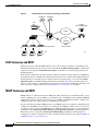
1
Cisco IOS Survivable Remote Site
Telephony Version 3.4 System
Administrator Guide
Cisco IOS Release
12.4(4)T
October 2005
Corporate Headquarters
Cisco Systems, Inc.
170 West Tasman Drive
San Jose, CA 95134-1706
USA
http://www.cisco.com
Tel: 408 526-4000
800 553-NETS (6387)
Fax: 408 526-4100
THE SPECIFICATIONS AND INFORMATION REGARDING THE PRODUCTS IN THIS MANUAL ARE SUBJECT TO CHANGE WITHOUT NOTICE. ALL
STATEMENTS, INFORMATION, AND RECOMMENDATIONS IN THIS MANUAL ARE BELIEVED TO BE ACCURATE BUT ARE PRESENTED WITHOUT
WARRANTY OF ANY KIND, EXPRESS OR IMPLIED. USERS MUST TAKE FULL RESPONSIBILITY FOR THEIR APPLICATION OF ANY PRODUCTS.
THE SOFTWARE LICENSE AND LIMITED WARRANTY FOR THE ACCOMPANYING PRODUCT ARE SET FORTH IN THE INFORMATION PACKET THAT
SHIPPED WITH THE PRODUCT AND ARE INCORPORATED HEREIN BY THIS REFERENCE. IF YOU ARE UNABLE TO LOCATE THE SOFTWARE LICENSE
OR LIMITED WARRANTY, CONTACT YOUR CISCO REPRESENTATIVE FOR A COPY.
The Cisco implementation of TCP header compression is an adaptation of a program developed by the University of California, Berkeley (UCB) as part of UCB’s public
domain version of the UNIX operating system. All rights reserved. Copyright © 1981, Regents of the University of California.
NOTWITHSTANDING ANY OTHER WARRANTY HEREIN, ALL DOCUMENT FILES AND SOFTWARE OF THESE SUPPLIERS ARE PROVIDED “AS IS” WITH
ALL FAULTS. CISCO AND THE ABOVE-NAMED SUPPLIERS DISCLAIM ALL WARRANTIES, EXPRESSED OR IMPLIED, INCLUDING, WITHOUT
LIMITATION, THOSE OF MERCHANTABILITY, FITNESS FOR A PARTICULAR PURPOSE AND NONINFRINGEMENT OR ARISING FROM A COURSE OF
DEALING, USAGE, OR TRADE PRACTICE.
IN NO EVENT SHALL CISCO OR ITS SUPPLIERS BE LIABLE FOR ANY INDIRECT, SPECIAL, CONSEQUENTIAL, OR INCIDENTAL DAMAGES, INCLUDING,
WITHOUT LIMITATION, LOST PROFITS OR LOSS OR DAMAGE TO DATA ARISING OUT OF THE USE OR INABILITY TO USE THIS MANUAL, EVEN IF CISCO
OR ITS SUPPLIERS HAVE BEEN ADVISED OF THE POSSIBILITY OF SUCH DAMAGES.
CCSP, CCVP, the Cisco Square Bridge logo, Follow Me Browsing, and StackWise are trademarks of Cisco Systems, Inc.; Changing the Way We Work, Live, Play, and Learn,
and iQuick Study are service marks of Cisco Systems, Inc.; and Access Registrar, Aironet, ASIST, BPX, Catalyst, CCDA, CCDP, CCIE, CCIP, CCNA, CCNP, Cisco, the
Cisco Certified Internetwork Expert logo, Cisco IOS, Cisco Press, Cisco Systems, Cisco Systems Capital, the Cisco Systems logo, Cisco Unity, Empowering the Internet
Generation, Enterprise/Solver, EtherChannel, EtherFast, EtherSwitch, Fast Step, FormShare, GigaDrive, GigaStack, HomeLink, Internet Quotient, IOS, IP/TV, iQ Expertise,
the iQ logo, iQ Net Readiness Scorecard, LightStream, Linksys, MeetingPlace, MGX, the Networkers logo, Networking Academy, Network Registrar, Packet, PIX,
Post-Routing, Pre-Routing, ProConnect, RateMUX, ScriptShare, SlideCast, SMARTnet, StrataView Plus, TeleRouter, The Fastest Way to Increase Your Internet Quotient,
and TransPath are registered trademarks of Cisco Systems, Inc. and/or its affiliates in the United States and certain other countries.
All other trademarks mentioned in this document or Website are the property of their respective owners. The use of the word partner does not imply a partnership relationship
between Cisco and any other company. (0502R)
Cisco IOS Survivable Remote Site Telephony Version 3.4 System Administrator Guide
Copyright © 2005 Cisco Systems, Inc. All rights reserved.
CONTENTS
Cisco IOS Survivable Remote Site Telephony Feature Roadmap
Contents
1
1
Documentation Organization
1
Feature Roadmap 3
Information About New Features in Cisco SRST V3.4 6
Information About New Features in Cisco SRST V3.3 7
Information About New Features in Cisco SRST V3.2 8
Information About New Features in Cisco SRST V3.1 10
Information About New Features in Cisco SRST V3.0 10
Information About Features That Were New in Cisco SRST V2.1 15
Information About Features That Were New in Cisco SRST V2.02 17
Overview of Cisco IOS SRST
Contents
19
19
Cisco SRST Description 19
H.323 Gateways and SRST 22
MGCP Gateways and SRST 22
Support for Cisco IP Phones, Platforms, Cisco CallManager, Signals, Languages, and Switches
Finding Cisco IOS Software Releases That Support Cisco SRST 23
Cisco IP Phone Support 24
Platform and Memory Support 24
Cisco CallManager Compatibility 25
Signal Support 25
Language Support 25
Switch Support 26
Prerequisites for Configuring Cisco SRST 26
Installing Cisco CallManager 27
Installing Cisco SRST 27
Integrating Cisco SRST with Cisco CallManager
Restrictions for Configuring Cisco SRST
Where to Go Next
23
27
28
30
Additional References 30
Related Documents 31
Standards 31
Cisco IOS Survivable Remote Site Telephony Version 3.4 System Administrator Guide
iii
Contents
MIBs 31
RFCs 32
Technical Assistance
Setting Up the Network
Contents
32
33
33
Information About Setting Up the Network
33
How to Set Up the Network 34
Enabling IP Routing 34
Enabling SRST on an MGCP Gateway 34
Configuring DHCP for Cisco SRST Phones 36
Specifying Keepalive Intervals 39
Configuring Cisco SRST to Support Phone Functions
Verifying That Cisco SRST Is Enabled 42
Where to Go Next
43
Setting Up Cisco IP Phones
Contents
40
45
45
Information About Setting Up Cisco IP Phones
45
How to Set Up Cisco IP Phones 45
Configuring IP Phone Clock, Date, and Time Formats 46
Configuring IP Phone Language Display 47
Configuring Customized System Messages for Cisco IP Phones
Configuring a Secondary Dial Tone 50
Configuring Dual-Line Phones 51
Where to Go Next
53
Setting Up Call Handling
Contents
55
55
Information About Setting Up Call Handling
55
How to Set Up Call Handling 55
Configuring Incoming Calls 56
Configuring Outgoing Calls 73
Where to Go Next
89
Configuring Additional Call Features
Contents
91
91
Information About Configuring Additional Call Features
How to Configure Additional Call Features 91
Enabling Three-Party G.711 Ad Hoc Conferencing
Cisco IOS Survivable Remote Site Telephony Version 3.4 System Administrator Guide
iv
91
92
48
Contents
Configuring MOH for G.711 VoIP and PSTN Calls
Configuring MOH from Flash Files 94
Defining XML API Schema 94
Where to Go Next
95
Setting Up Secure SRST
Contents
93
97
97
Prerequisites for Setting Up Secure SRST
Restrictions for Setting Up Secure SRST
97
98
Information About Setting Up Secure SRST 99
Benefits of Secure SRST 99
Cisco IP Phones Clear-Text Fallback During SRST 100
SRST Routers and the TLS Protocol 100
SRST Routers and PKI 101
Secure SRST Authentication and Encryption 102
Cisco IOS Credentials Server on Secure SRST Routers 103
Establishment of Secure SRST to the Cisco IP Phone 103
How to Configure Secure SRST 105
Preparing the SRST Router for Secure Communication 105
Importing Phone Certificate Files in PEM Format to the Secure SRST Router
Configuring Cisco CallManager to the Secure SRST Router 118
Enabling SRST Mode on the Secure SRST Router 121
Verifying Phone Status and Registrations 123
114
Configuration Examples for Secure SRST 127
Secure SRST: Example 127
Control Plane Policing: Example 132
Where to Go Next
133
Additional References 133
Related Documents 133
Standards 134
MIBs 134
RFCs 134
Technical Assistance 134
Integrating Voice Mail with Cisco SRST
Contents
135
135
Information About Integrating Voice Mail with Cisco SRST
135
How to Integrate Voice Mail with Cisco SRST 137
Configuring Direct Access to Voice Mail 137
Cisco IOS Survivable Remote Site Telephony Version 3.4 System Administrator Guide
v
Contents
Configuring Message Buttons 140
Redirecting to Cisco CallManager Gateway 142
Configuring Call Forwarding to Voice Mail 142
Configuring Message Waiting Indication 147
Configuration Examples 149
Configuring Local Voice-Mail System (FXO and FXS): Example 149
Configuring Central Location Voice-Mail System (FXO and FXS): Example
Configuring Voice-Mail Access over FXO and FXS: Example 150
Configuring Voice-Mail Access over BRI and PRI: Example 151
Where to Go Next
151
Monitoring and Maintaining Cisco SRST
153
Appendix A: Preparing Cisco SRST Support for SIP
Contents
155
155
DTMF Relay for SIP Applications and Voice Mail
DTMF Relay Using SIP RFC 2833 155
DTMF Relay Using SIP Notify (Nonstandard)
155
157
INDEX
Cisco IOS Survivable Remote Site Telephony Version 3.4 System Administrator Guide
vi
150
Cisco IOS Survivable Remote Site Telephony Fea
ture Roadmap
This chapter contains a list of Cisco IOS SRST features and the location of feature documentation.
Use Cisco Feature Navigator to find information about platform support and Cisco IOS software image
support. Access Cisco Feature Navigator at http://www.cisco.com/go/fn. You must have an account on
Cisco.com. If you do not have an account or have forgotten your username or password, click Cancel at
the login dialog box and follow the instructions that appear.
Note
The Cisco IOS Voice Configuration Library includes a standard library preface, a glossary, and feature
and troubleshooting documents and is located at
http://www.cisco.com/univercd/cc/td/doc/product/software/ios123/123cgcr/vcl.htm.
Contents
•
Documentation Organization, page 1
•
Feature Roadmap, page 3
Documentation Organization
This document consists of the following chapters or appendixes as shown in Table 1.
Cisco IOS Survivable Remote Site Telephony Version 3.4 System Administrator Guide
1
Cisco IOS Survivable Remote Site Telephony Fea ture Roadmap
Documentation Organization
Table 1
Cisco SRST Configuration Sequence
Chapter or Appendix
Description
Overview of Cisco IOS SRST
Provides a summary of SRST. This chapter includes the following
sections:
Setting Up the Network
Setting Up Cisco IP Phones
Setting Up Call Handling
Configuring Additional Call Features
•
Cisco SRST Description, page 19
•
Support for Cisco IP Phones, Platforms, Cisco CallManager,
Signals, Languages, and Switches, page 23
•
Prerequisites for Configuring Cisco SRST, page 26
•
Restrictions for Configuring Cisco SRST, page 28
•
Additional References, page 30
Describes how to set up a Cisco SRST system to communicate with
your network. This chapter includes the following tasks:
•
Enabling IP Routing, page 34
•
Configuring DHCP for Cisco SRST Phones, page 36
•
Specifying Keepalive Intervals, page 39
•
Configuring Cisco SRST to Support Phone Functions, page 40
•
Verifying That Cisco SRST Is Enabled, page 42
Describes how to set up the basic Cisco SRST phone configuration.
This chapter includes the following tasks:
•
Configuring IP Phone Clock, Date, and Time Formats, page 46
•
Configuring IP Phone Language Display, page 47
•
Configuring Customized System Messages for Cisco IP Phones,
page 48
•
Configuring a Secondary Dial Tone, page 50
•
Configuring Dual-Line Phones, page 51
Describes how to configure incoming and outgoing calls. This
chapter includes the following tasks:
•
Configuring Incoming Calls, page 56
•
Configuring Outgoing Calls, page 73
Describes how to configure optional system and phone parameters.
This chapter includes the following tasks:
•
Enabling Three-Party G.711 Ad Hoc Conferencing, page 92
•
Configuring MOH for G.711 VoIP and PSTN Calls, page 93
•
Configuring MOH from Flash Files, page 94
Cisco IOS Survivable Remote Site Telephony Version 3.4 System Administrator Guide
2
Cisco IOS Survivable Remote Site Telephony Fea ture Roadmap
Feature Roadmap
Table 1
Cisco SRST Configuration Sequence (continued)
Chapter or Appendix
Description
Setting Up Secure SRST
Describes the Media and Signaling Authentication and Encryption
feature for Cisco IOS MGCP gateways in SRST mode. This chapter
includes the following tasks:
Integrating Voice Mail with Cisco SRST
•
Preparing the SRST Router for Secure Communication,
page 105
•
Importing Phone Certificate Files in PEM Format to the Secure
SRST Router, page 114
•
Configuring Cisco CallManager to the Secure SRST Router,
page 118
•
Enabling SRST Mode on the Secure SRST Router, page 121
•
Verifying Phone Status and Registrations, page 123
Describes how to set up voice mail. This chapter includes the
following tasks:
•
Configuring Direct Access to Voice Mail, page 137
•
Configuring Message Buttons, page 140
•
Redirecting to Cisco CallManager Gateway, page 142
•
Configuring Call Forwarding to Voice Mail, page 142
Monitoring and Maintaining Cisco SRST
Provides a list of useful show commands for monitoring and
maintaining SRST.
Appendix A: Preparing Cisco SRST Support for SIP
Describes special configurations to support SIP calls.
Feature Roadmap
Table 2 provides a feature history summary of Cisco IOS SRST features.
Table 2
Cisco IOS SRST Features by Cisco IOS Release
Cisco SRST Version Cisco IOS Release
Modifications
Version 3.4
12.4(4)T
•
SIP SRST, Version 3.4, page 6
Version 3.3
12.3(14)T
•
Secure SRST, page 7.
•
Cisco IP Phone 7970G and Cisco 7971G-GE Support, page 7
•
Enhancement to the show ephone Command, page 8
Cisco IOS Survivable Remote Site Telephony Version 3.4 System Administrator Guide
3
Cisco IOS Survivable Remote Site Telephony Fea ture Roadmap
Feature Roadmap
Table 2
Cisco IOS SRST Features by Cisco IOS Release (continued)
Cisco SRST Version Cisco IOS Release
Version 3.2
Version 3.1
Version 3.0
12.3(11)T
12.3(7)T
12.3(4)T
12.2(15)ZJ
Modifications
•
Enhancement to the alias Command, page 8
•
Enhancement to the pickup Command, page 8
•
Enhancement to the user-locale Command, page 9
•
Enhancement to the user-locale Command, page 9
•
Increased the Number of Cisco IP Phones Supported on the Cisco 3845,
page 9
•
MOH Live-Feed Support, page 9
•
No Timeout for Call Preservation, page 9
•
RFC 2833 DTMF Relay Support, page 9
•
Translation Profile Support, page 9
•
Cisco IP Phone 7920 Support, page 10
•
Cisco IP Phone 7936 Support, page 10
—
•
Additional Language Options for IP Phone Display, page 11
•
Consultative Call Transfer and Forward Using H.450.2 and H.450.3, page 11
•
Customized System Message for Cisco IP Phones, page 12
•
Dual-Line Mode, page 12
•
E1 R2 Signaling Support, page 12
•
European Date Formats, page 13
•
Huntstop for Dual-Line Mode, page 13
•
Music on Hold for Multicast from Flash Files, page 13
•
Ringing Timeout Default, page 14
•
Secondary Dial Tone, page 14
•
Enhancement to the show ephone Command, page 14
•
System Log Messages for Phone Registrations, page 14
•
Three-Party G.711 Ad Hoc Conferencing, page 14
•
Support for Cisco VG248 Analog Phone Gateway Version 1.2(1) and Higher,
page 14
Cisco IOS Survivable Remote Site Telephony Version 3.4 System Administrator Guide
4
Cisco IOS Survivable Remote Site Telephony Fea ture Roadmap
Feature Roadmap
Table 2
Cisco IOS SRST Features by Cisco IOS Release (continued)
Cisco SRST Version Cisco IOS Release
Version 2.1
12.2(15)T1
12.2(15)T
12.2(11)YT
Version 2.02
Version 2.01
Version 2.0
12.2(13)T
12.2(11)T
Modifications
•
Cisco IP Phone 7902G Support, page 16
•
Cisco IP Phone 7912G Support, page 16
—
•
Additional Language Options for IP Phone Display, page 15
•
Cisco SRST Aggregation, page 15
•
Cisco ATA 186 and ATA 188 Support, page 16
•
Cisco IP Phone 7905G Support, page 16
•
Cisco IP Phone Expansion Module 7914 Support, page 17
•
Enhancement to the dialplan-pattern Command, page 17
•
Cisco IP Phone Conference Station 7935 Support, page 17.
•
Increase in Directory Numbers, page 17.
•
Unity Voice Mail Integration Using In-Band DTMF Signaling Across the
PSTN and BRI/PRI, page 18.
•
Cisco SRST was implemented on the Cisco Catalyst 4500 access gateway
module and Cisco 7200 routers (NPE-225, NPE-300, and NPE400).
•
Support was removed for the Cisco MC3810-V3 concentrator.
•
Cisco SRST was implemented on the Cisco 1760 routers, and support for the
Cisco 1750 was removed.
•
Support was added for additional connected Cisco IP phones.
•
Support was added for additional directory numbers or virtual voice ports on
Cisco IP phones.
12.2(8)T1
Cisco SRST was implemented on the Cisco 2600XM and Cisco 2691 routers.
12.2(8)T
Cisco SRST was integrated into Cisco IOS Release 12.2(8)T and implemented on
the Cisco 3725 and Cisco 3745 routers and the Cisco MC3810-V3 concentrators.
12.2(2)XT
•
Cisco SRST was implemented on the Cisco 1750 and Cisco 1751 routers.
•
Huntstop support.
•
Class of restriction (COR).
•
Translation rule support.
•
Music on hold and tone on hold.
•
Distinctive ringing.
•
Forward to a central voice mail or auto-attendant (AA) through PSTN during
Cisco CallManager fallback.
•
Phone number alias support during Cisco CallManager fallback: enhanced
default destination support.
•
List-based call restrictions for Cisco CallManager fallback.
Cisco IOS Survivable Remote Site Telephony Version 3.4 System Administrator Guide
5
Cisco IOS Survivable Remote Site Telephony Fea ture Roadmap
Feature Roadmap
Table 2
Cisco IOS SRST Features by Cisco IOS Release (continued)
Cisco SRST Version Cisco IOS Release
Modifications
Version 1.0
Support was added for 144 Cisco IP phones on the Cisco 3660 multiservice
routers.
12.1(5)YD1
12.1(5)YD
•
Cisco SRST introduced on the Cisco 2600 series and Cisco 3600 series
multiservice routers and the Cisco IAD2420 series integrated access devices.
•
Cisco IP phones able to establish a connection with an SRST router in the
event of a WAN link to Cisco CallManager failure.
•
Dimming of all Cisco IP phone function keys that are not supported during
Cisco SRST operation.
•
Extension-to-extension dialing.
•
Direct Inward Dialing (DID).
•
Direct Outward Dialing (DOD).
•
Calling party ID (Caller ID/ANI) display.
•
Last number redial.
•
Preservation of local extension-to-extension calls when WAN link fails.
•
Preservation of local extension to PSTN calls when WAN link fails.
•
Preservation of calls in progress when failed WAN link is reestablished.
•
Blind transfer of calls within IP network.
•
Multiple lines per Cisco IP phone.
•
Multiple-line appearance across telephones.
•
Call hold (shared lines).
•
Analog Foreign Exchange Station (FXS) and Foreign Exchange Office
(FXO) ports.
•
BRI support for EuroISDN.
•
PRI support for NET5 switch type.
Information About New Features in Cisco SRST V3.4
Cisco SRST V3.4 introduced the new features described in the following section:
•
SIP SRST, Version 3.4
SIP SRST, Version 3.4
Cisco SIP SRST Version 3.4 describes SRST functionality for Session Initiation Protocol (SIP)
networks. Cisco SIP SRST Version 3.4 provides backup to an external SIP proxy server by providing
basic registrar and back-to-back user agent (B2BUA) services. These services are used by a SIP IP phone
in the event of a WAN connection outage when the SIP phone is unable to communicate with its primary
SIP proxy.
Cisco IOS Survivable Remote Site Telephony Version 3.4 System Administrator Guide
6
Cisco IOS Survivable Remote Site Telephony Fea ture Roadmap
Feature Roadmap
Cisco SIP SRST Version 3.4 can support SIP phones with standard RFC 3261 feature support locally
and across SIP WAN networks. With Cisco SIP SRST Version 3.4, SIP phones can place calls across
SIP networks in the same way as Skinny Client Control Protocol (SCCP) phones. For full information
about SIP SRST, Version 3.4 see the Cisco IOS SIP SRST Version 3.4 System Administrator Guide.
Information About New Features in Cisco SRST V3.3
Cisco SRST V3.3 introduced the new features described in the following sections:
•
Secure SRST
•
Cisco IP Phone 7970G and Cisco 7971G-GE Support
•
Enhancement to the show ephone Command
Secure SRST
Secure Cisco IP phones that are located at remote sites and that are attached to gateway routers can
communicate securely with Cisco CallManager using the WAN. But if the WAN link or Cisco
CallManager goes down, all communication through the remote phones becomes nonsecure. To
overcome this situation, gateway routers can now function in secure SRST mode, which activates when
the WAN link or Cisco CallManager goes down. When the WAN link or Cisco CallManager is restored,
Cisco CallManager resumes secure call-handling capabilities.
Secure SRST provides new SRST security features such as authentication, integrity, and media
encryption. Authentication provides assurance to one party that another party is whom it claims to be.
Integrity provides assurance that the given data has not been altered between the entities. Encryption
implies confidentiality; that is, that no one can read the data except the intended recipient. These security
features allow privacy for SRST voice calls and protect against voice security violations and identity
theft. For more information see the chapter “Setting Up Secure SRST” section on page 97.
Cisco IP Phone 7970G and Cisco 7971G-GE Support
The Cisco IP Phones 7970G and Cisco 7971G-GE are full-featured telephones that provide voice
communication over an IP network. They function much like a traditional analog telephones, allowing
you to place and receive phone calls and to access features such as mute, hold, transfer, speed dial, call
forward, and more. In addition, because the phones are connected to your data network, they offer
enhanced IP telephony features, including access to network information and services, and
customizeable features and services. The phones also support security features that include file
authentication, device authentication, signaling encryption, and media encryption.
The Cisco IP Phones 7970G and Cisco 7971G-GE also provide a color touchscreen, support for up to
eight line or speed-dial numbers, context-sensitive online help for buttons and feature, and a variety of
other sophisticated functions. No configurations specific to SRST are necessary.
For more information, see the following URL:
http://www.cisco.com/univercd/cc/td/doc/product/voice/c_ipphon/english/ipp7970/index.htm
Note
The Cisco IP Phone 7914 Expansion Module can attach to your Cisco IP phones 7970G and Cisco
7971G-GE. See Cisco IP Phone Expansion Module 7914 Support, page 17 for more information.
Cisco IOS Survivable Remote Site Telephony Version 3.4 System Administrator Guide
7
Cisco IOS Survivable Remote Site Telephony Fea ture Roadmap
Feature Roadmap
Enhancement to the show ephone Command
The show ephone command has been enhanced to display the configuration and status of the
Cisco 7970G and Cisco 7971G-GE phones. For more information, see the show ephone command in the
Cisco IOS Survivable Remote Site Telephony (SRST) Command Reference (All Versions).
Information About New Features in Cisco SRST V3.2
Cisco SRST V3.2 introduced the new features described in the following sections:
•
Enhancement to the alias Command
•
Enhancement to the cor Command
•
Enhancement to the pickup Command
•
Enhancement to the user-locale Command
•
Increased the Number of Cisco IP Phones Supported on the Cisco 3845
•
MOH Live-Feed Support
•
No Timeout for Call Preservation
•
RFC 2833 DTMF Relay Support
•
Translation Profile Support
Enhancement to the alias Command
The alias command has been enhanced as follows:
•
The cfw keyword was added, providing call forward no-answer/busy capabilities.
•
The maximum number of alias commands used for creating calls to telephone numbers that are
unavailable during Cisco CallManager fallback was increased to 50.
•
The alternate-number argument can be used in multiple alias commands.
For more information, see the alias command in the Cisco IOS Survivable Remote Site Telephony (SRST)
Command Reference (All Versions).
Enhancement to the cor Command
The maximum number of cor lists has been increased to 20.
For more information, see the cor command in the Cisco IOS Survivable Remote Site Telephony (SRST)
Command Reference (All Versions).
Enhancement to the pickup Command
The pickup command has been introduced to enable the PickUp soft key on all Cisco IP phones,
allowing an external Direct Inward Dialing (DID) call coming into one extension to be picked up from
another extension during SRST.
For more information, see the pickup command in the Cisco IOS Survivable Remote Site Telephony
(SRST) Command Reference (All Versions).
Cisco IOS Survivable Remote Site Telephony Version 3.4 System Administrator Guide
8
Cisco IOS Survivable Remote Site Telephony Fea ture Roadmap
Feature Roadmap
Enhancement to the user-locale Command
Theuser-locale command has been enhanced to display the Japanese Katakana country code. Japanese
Katakana is available under Cisco CallManager V4.0 or later.
For more information, see the user-locale command in the Cisco IOS Survivable Remote Site Telephony
(SRST) Command Reference (All Versions).
Increased the Number of Cisco IP Phones Supported on the Cisco 3845
The Cisco 3845 now supports 720 phones and up to 960 ephone-dns or virtual voice ports. For more
information, see Cisco IOS Survivable Remote Site Telephony (SRST) 3.2 Specifications for Cisco IOS
Software Release 12.3(11)T.
MOH Live-Feed Support
Cisco SRST has been enhanced with the new moh-live command. The moh-live command provides
live-feed MOH streams from an audio device connected to an E&M or FXO port to Cisco IP phones in
SRST mode. If an FXO port is used for a live feed, the port must be supplied with an external third-party
adapter to provide a battery feed. Music from a live feed is obtained from a fixed source and is
continuously fed into the MOH playout buffer instead of being read from a flash file. Live-feed MOH
can also be multicast to Cisco IP phones. See Configuring SRST MOH Live-Feed Support for
configuration instructions.
No Timeout for Call Preservation
To preserve existing H.323 calls on the branch in the event of an outage, disable the H.225 keepalive
timer by entering the no h225 timeout keepalive command. This feature is supported in Cisco IOS
Releases 12.3(7)T1 and higher. See the “Cisco SRST Description” section on page 19 for more
information.
RFC 2833 DTMF Relay Support
Cisco Skinny Client Control Protocol (SCCP) phones, such as those used with Cisco SRST systems,
provide only out-of-band DTMF digit indications. To enable SCCP phones to send digit information to
remote SIP-based IVR and voice-mail applications, Cisco SRST 3.2 and later versions provide
conversion from the out-of-band SCCP digit indication to the SIP standard for DTMF relay, which is
RFC 2833. You select this method in the SIP VoIP dial peer using the dtmf-relay rtp-nte command.
See Appendix A: Preparing Cisco SRST Support for SIP, page 155 for configuration instructions.
To use voice mail on a SIP network that connects to a Cisco Unity Express (CUE) system, use a
nonstandard SIP Notify format. To configure the Notify format, use the sip-notify keyword with the
dtmf-relay command. Using the sip-notify keyword may be required for backward compatibility with
Cisco SRST Versions 3.0 and 3.1.
Translation Profile Support
Cisco SRST 3.2 and later versions support translation profiles. Translation profiles allow you to group
translation rules together and to associate translation rules with the following:
•
Called numbers
•
Calling numbers
Cisco IOS Survivable Remote Site Telephony Version 3.4 System Administrator Guide
9
Cisco IOS Survivable Remote Site Telephony Fea ture Roadmap
Feature Roadmap
•
Redirected called numbers
See the “Enabling Translation Profiles” section on page 66 for more configuration information. For
more information on thetranslation-profile, command see the Cisco IOS Survivable Remote Site
Telephony (SRST) Command Reference (All Versions).
Information About New Features in Cisco SRST V3.1
Cisco SRST V3.1 introduced the new features described in the following sections:
•
Cisco IP Phone 7920 Support
•
Cisco IP Phone 7936 Support
Cisco IP Phone 7920 Support
The Cisco Wireless IP Phone 7920 is an easy-to-use IEEE 802.11b wireless IP phone that provides
comprehensive voice communications in conjunction with Cisco CallManager and Cisco Aironet 1200,
1100, 350, and 340 Series of Wi-Fi (IEEE 802.11b) access points. As a key part of the Cisco AVVID
Wireless Solution, the Cisco Wireless IP Phone 7920 delivers seamless intelligent services, such as
security, mobility, quality of service (QoS), and management, across an end-to-end Cisco network.
No configuration is necessary.
For more information, see the following URL:
http://www.cisco.com/univercd/cc/td/doc/product/voice/c_ipphon/english/wip7920/
Cisco IP Phone 7936 Support
The Cisco IP Conference Station 7936 is an IP-based, hands-free conference room station that uses VoIP
technology. The IP Conference Station replaces a traditional analog conferencing unit by providing
business conferencing features—such as call hold, call resume, call transfer, call release, redial, mute,
and conference—over an IP network.
No configuration is necessary.
For more information, see the following URL:
http://www.cisco.com/univercd/cc/td/doc/product/voice/c_ipphon/english/ipp7936/
Information About New Features in Cisco SRST V3.0
Cisco SRST V3.0 introduced the new features described in the following sections:
•
Additional Language Options for IP Phone Display
•
Consultative Call Transfer and Forward Using H.450.2 and H.450.3
•
Customized System Message for Cisco IP Phones
•
Dual-Line Mode
•
E1 R2 Signaling Support
•
European Date Formats
•
Huntstop for Dual-Line Mode
Cisco IOS Survivable Remote Site Telephony Version 3.4 System Administrator Guide
10
Cisco IOS Survivable Remote Site Telephony Fea ture Roadmap
Feature Roadmap
•
Music on Hold for Multicast from Flash Files
•
Ringing Timeout Default
•
Secondary Dial Tone
•
Enhancement to the show ephone Command
•
System Log Messages for Phone Registrations
•
Three-Party G.711 Ad Hoc Conferencing
•
Support for Cisco VG248 Analog Phone Gateway Version 1.2(1) and Higher
Additional Language Options for IP Phone Display
Displays for the Cisco IP Phone 7940G and Cisco IP Phone 7960G can be configured with additional
ISO-3166 codes for Denmark, The Netherlands, Norway, and Sweden.
Note
This feature is available only for Cisco SRST running under Cisco CallManager V3.2.
Consultative Call Transfer and Forward Using H.450.2 and H.450.3
Cisco SRST V1.0, Cisco SRST V2.0, and Cisco SRST V2.1 allow blind call transfers and blind call
forwarding. Blind calls do not give transferring and forwarding parties the ability to announce or consult
with destination parties. These three versions of Cisco SRST use a Cisco SRST proprietary mechanism
to perform blind transfers. Cisco SRST V3.0 adds the ability to perform call transfers with consultation
using the ITU-T H.450.2 (H.450.2) standard and call forwarding using the ITU-T H.450.3 (H.450.3)
standard for H.323 calls.
Cisco SRST V3.0 provides support for IP phones to initiate call transfer and forwarding with H.450.2
and H.450.3 by using the default session application. The built-in H.450.2 and H.450.3 support that is
provided by the default session application applies to call transfers and call forwarding initiated by IP
phones, regardless of PSTN interface type.
For consultative transfer to be available, the Cisco SRST router must be configured with the dual-line
mode. See the “Configuring Dual-Line Phones” section on page 51.
Note
All voice gateway routers in the VoIP network must support H.450. For H.450 support, routers with
Cisco SRST must run either Cisco SRST V3.0 and higher versions or Cisco IOS Release 12.2(15)ZJ and
later releases. Routers without Cisco SRST must run either Cisco SRST V2.1 and higher versions or
Cisco IOS Release 12.2(11)YT and later releases.
For more information about the default session application, see the Default Session Application
Enhancements document.
For configuration information, see the “Enabling Consultative Call Transfer and Forward Using H.450.2
and H.450.3 with Cisco SRST V3.0” section on page 74.
Cisco IOS Survivable Remote Site Telephony Version 3.4 System Administrator Guide
11
Cisco IOS Survivable Remote Site Telephony Fea ture Roadmap
Feature Roadmap
Customized System Message for Cisco IP Phones
The display message that appears on Cisco IP Phone 7905G, Cisco IP Phone 7940G, Cisco IP Phone
7960G, and Cisco IP Phone 7910 units when they are in fallback mode can be customized. The new
system message command allows you to edit these display messages on a per-router basis. The custom
system message feature supports English only.
For further information, see the “Configuring Customized System Messages for Cisco IP Phones”
section on page 48.
Dual-Line Mode
A new keyword that has been added to the max-dn command allows you to set IP phones to dual-line
mode. Each dual-line IP phone must have one voice port and two channels to handle two independent
calls. This mode enables call waiting, call transfer, and conference functions on a single ephone-dn
(ephone directory number). There is a maximum number of DNs available during Cisco SRST fallback.
The max-dn command affects all IP phones on a Cisco SRST router.
For configuration information, see the “Configuring Dual-Line Phones” section on page 51.
E1 R2 Signaling Support
Cisco SRST V3.0 supports E1 R2 signaling. R2 signaling is an international signaling standard that is
common to channelized E1 networks; however, there is no single signaling standard for R2. The ITU-T
Q.400-Q.490 recommendation defines R2, but a number of countries and geographic regions implement
R2 in entirely different ways. Cisco Systems addresses this challenge by supporting many localized
implementations of R2 signaling in its Cisco IOS software.
The Cisco Systems E1 R2 signaling default is ITU, which supports the following countries: Denmark,
Finland, Germany, Russia (ITU variant), Hong Kong (ITU variant), and South Africa (ITU variant). The
expression “ITU variant” means there are multiple R2 signaling types in the specified country, but Cisco
supports the ITU variant.
Cisco Systems also supports specific local variants of E1 R2 signaling in the following regions,
countries, and corporations:
•
Argentina
•
Australia
•
Bolivia
•
Brazil
•
Bulgaria
•
China
•
Colombia
•
Costa Rica
•
East Europe (includes Croatia, Russia, and Slovak Republic)
•
Ecuador (ITU)
•
Ecuador (LME)
•
Greece
•
Guatemala
Cisco IOS Survivable Remote Site Telephony Version 3.4 System Administrator Guide
12
Cisco IOS Survivable Remote Site Telephony Fea ture Roadmap
Feature Roadmap
•
Hong Kong (uses the China variant)
•
Indonesia
•
Israel
•
Korea
•
Laos
•
Malaysia
•
Malta
•
New Zealand
•
Paraguay
•
Peru
•
Philippines
•
Saudi Arabia
•
Singapore
•
South Africa (Panaftel variant)
•
Telmex corporation (Mexico)
•
Telnor corporation (Mexico)
•
Thailand
•
Uruguay
•
Venezuela
•
Vietnam
European Date Formats
The date format on Cisco IP phone displays can be configured with the following two additional
formats:
•
yy-mm-dd (year-month-day)
•
yy-dd-mm (year-day-month)
For configuration information, see the “Configuring IP Phone Clock, Date, and Time Formats” section
on page 46.
Huntstop for Dual-Line Mode
A new keyword has been added to the huntstop command. The channel keyword causes hunting to skip
the secondary channel in dual-line configuration if the primary line is busy or does not answer.
For configuration information, see the “Configuring Dial-Peer and Channel Hunting” section on
page 70.
Music on Hold for Multicast from Flash Files
Cisco SRST can be configured to support continuous multicast output of music on hold (MOH) from a
flash MOH file in flash memory.
Cisco IOS Survivable Remote Site Telephony Version 3.4 System Administrator Guide
13
Cisco IOS Survivable Remote Site Telephony Fea ture Roadmap
Feature Roadmap
For more information, see the “Configuring MOH from Flash Files” section on page 94.
Ringing Timeout Default
A ringing timeout default can be configured for extensions on which no-answer call forwarding has not
been enabled. Expiration of the timeout causes incoming calls to return a disconnect code to the caller.
This mechanism provides protection against hung calls for inbound calls received over interfaces such
as Foreign Exchange Office (FXO) that do not have forward-disconnect supervision. For more
information, see the “Configuring the Ringing Timeout Default” section on page 72.
Secondary Dial Tone
A secondary dial tone is available for Cisco IP phones running Cisco SRST. The secondary dial tone is
generated when a user dials a predefined PSTN access prefix. An example would be the different dial
tone heard when a designated number is pressed to reach an outside line.
The secondary dial tone is created through the secondary dialtone command. For more information, see
the “Configuring a Secondary Dial Tone” section on page 50.
Enhancement to the show ephone Command
The show ephone command has been enhanced to display the following:
•
The configuration and status of additional phones (new keywords: 7905, 7914, 7935, ATA)
•
The status of all phones with the call-forwarding all (CFA) feature enabled on at least one of their
DNs (new keyword: cfa)
For more information, see the show ephone command in the Cisco IOS Survivable Remote Site
Telephony (SRST) Command Reference (All Versions).
System Log Messages for Phone Registrations
Diagnostic messages are added to the system log whenever a phone registers or unregisters from
Cisco SRST.
Three-Party G.711 Ad Hoc Conferencing
Cisco SRST supports three-party ad hoc conferencing using the G.711 coding technique. For
conferencing to be available, an IP phone must have a minimum of two lines connected to one or more
buttons.
For more information, see the “Enabling Three-Party G.711 Ad Hoc Conferencing” section on page 92.
Support for Cisco VG248 Analog Phone Gateway Version 1.2(1) and Higher
The Cisco VG248 Analog Phone Gateway is a mixed-environment solution, enabled by Cisco AVVID
(Architecture for Voice, Video and Integrated Data), that allows organizations to support their legacy
analog devices while taking advantage of the new opportunities afforded through the use of IP
telephony. The Cisco VG248 is a high-density gateway for using analog phones, fax machines, modems,
voice-mail systems, and speakerphones within an enterprise voice system based on Cisco CallManager.
Cisco IOS Survivable Remote Site Telephony Version 3.4 System Administrator Guide
14
Cisco IOS Survivable Remote Site Telephony Fea ture Roadmap
Feature Roadmap
During Cisco CallManager fallback, Cisco SRST considers the Cisco VG248 to be a group of Cisco IP
phones. Cisco SRST counts each of the 48 ports on the Cisco VG248 as a separate Cisco IP phone.
Support for Cisco VG248 Version 1.2(1) and higher is also available in Cisco SRST Version 2.1.
For more information, see the Cisco VG248 Analog Phone Gateway Data Sheet and the Cisco VG248
Analog Phone Gateway Version 1.2(1) Release Notes.
Information About Features That Were New in Cisco SRST V2.1
Cisco SRST V2.1 introduced the new features described in the following sections:
•
Additional Language Options for IP Phone Display
•
Cisco SRST Aggregation
•
Cisco ATA 186 and ATA 188 Support
•
Cisco IP Phone 7902G Support
•
Cisco IP Phone 7905G Support
•
Cisco IP Phone 7912G Support
•
Cisco IP Phone Expansion Module 7914 Support
•
Enhancement to the dialplan-pattern Command
Additional Language Options for IP Phone Display
Displays for the Cisco IP Phone 7940G and Cisco IP Phone 7960G can be configured with ISO-3166
codes for the following countries:
Note
•
France
•
Germany
•
Italy
•
Portugal
•
Spain
•
United States
This feature is available only in Cisco SRST running under Cisco CallManager V3.2.
For configuration information, see the “Configuring IP Phone Language Display” section on page 47.
Cisco SRST Aggregation
For systems running Cisco CallManager 3.3(2) and later, the restriction of running Cisco SRST on a
default gateway was removed. Multiple SRST routers can be used to support additional phones. Note
that dial peers and dial plans need to be carefully planned and configured in order for call transfer and
forwarding to work properly.
Cisco IOS Survivable Remote Site Telephony Version 3.4 System Administrator Guide
15
Cisco IOS Survivable Remote Site Telephony Fea ture Roadmap
Feature Roadmap
Cisco ATA 186 and ATA 188 Support
The Cisco ATA analog telephone adaptors are handset-to-Ethernet adaptors that allow regular analog
telephones to operate on IP-based telephony networks. Cisco ATAs support two voice ports, each with
an independent telephone number. The Cisco ATA 188 also has an RJ-45 10/100BASE-T data port.
Cisco SRST supports Cisco ATA 186 and Cisco ATA 188 using Skinny Client Control Protocol (SCCP)
for voice calls only.
Cisco IP Phone 7902G Support
The Cisco IP Phone 7902G is an entry-level IP phone that addresses the voice communications needs of
a lobby, laboratory, manufacturing floor, hallway, or other area where only basic calling capability is
required.
The Cisco IP Phone 7902G is a single-line IP phone with fixed feature keys that provide one-touch
access to the redial, transfer, conference, and voice-mail access features. Consistent with other
Cisco IP phones, the Cisco IP Phone 7902G supports inline power, which allows the phone to receive
power over the LAN. This capability gives the network administrator centralized power control and thus
greater network availability.
For further information, go to Cisco.com and click Products & Solutions > Voice & IP
Communications > 7900 Series IP Phones > Product Literature > Data Sheets or go to
http://www.cisco.com/univercd/cc/td/doc/product/voice/c_ipphon/english/ipp7902/index.htm.
Cisco IP Phone 7905G Support
The Cisco IP Phone 7905G is a basic IP phone that provides a core set of business features. It provides
single-line access and four interactive soft keys that guide a user through call features and functions via
the pixel-based liquid crystal display (LCD). The graphic capability of the display presents calling
information, intuitive access to features, and language localization in future firmware releases. The
Cisco IP Phone 7905G supports inline power, which allows the phone to receive power over the LAN.
No configuration is necessary.
For more information, see the following URL:
http://www.cisco.com/univercd/cc/td/doc/product/voice/c_ipphon/7905_g/index.htm
Cisco IP Phone 7912G Support
The Cisco IP Phone 7912G provides core business features and addresses the communication needs of
a cubicle worker who conducts low to medium telephone traffic. Four dynamic soft keys provide access
to call features and functions. The graphic display shows calling information and allows access to
features.
The Cisco IP Phone 7912G supports an integrated Ethernet switch, providing LAN connectivity to a
local PC. In addition, the Cisco IP Phone 7912G supports inline power, which allows the phone to
receive power over the LAN. This capability gives the network administrator centralized power control
and thus greater network availability. The combination of inline power and Ethernet switch support
reduces cabling needs to a single wire to the desktop.
For further information, go to Cisco.com and click Products & Solutions > Voice & IP
Communications > 7900 Series IP Phones > Product Literature > Data Sheets.
Cisco IOS Survivable Remote Site Telephony Version 3.4 System Administrator Guide
16
Cisco IOS Survivable Remote Site Telephony Fea ture Roadmap
Feature Roadmap
Cisco IP Phone Expansion Module 7914 Support
The Cisco IP Phone 7914 Expansion Module attaches to your Cisco IP Phone 7960G, adding 14 line
appearances or speed-dial numbers to your phone. You can attach one or two expansion modules to your
IP phone. When you use two expansion modules, you have 28 additional line appearances or speed-dial
numbers, or a total of 34 line appearances or speed-dial numbers.
No configuration is necessary.
For more information, see the Cisco IP Phone 7914 Expansion Module Quick Start Guide.
Enhancement to the dialplan-pattern Command
A new keyword has been added to the dialplan-pattern command. The extension-pattern keyword sets
an extension number’s leading digit pattern when it is different from the E.164 telephone number’s
leading digits defined in the pattern variable. This enhancement allows manipulation of IP phone
abbreviated extension number prefix digits. See the dialplan-pattern command in the
Cisco IOS Survivable Remote Site Telephony (SRST) Command Reference (All Versions).
Information About Features That Were New in Cisco SRST V2.02
Cisco SRST Version 2.02 introduced the new features described in the following sections:
•
Cisco IP Phone Conference Station 7935 Support
•
Increase in Directory Numbers
•
Unity Voice Mail Integration Using In-Band DTMF Signaling Across the PSTN and BRI/PRI
Cisco IP Phone Conference Station 7935 Support
The Cisco IP Conference Station 7935 is an IP-based, full-duplex hands-free conference station for use
on desktops and offices and in small-to-medium-sized conference rooms. This device attaches a Cisco
Catalyst 10/100 Ethernet switch port with a simple RJ-45 connection and dynamically configures itself
to the IP network via the DHCP. Other than connecting the Cisco 7935 to an Ethernet switch port, no
further administration is necessary. The Cisco 7935 dynamically registers to Cisco CallManager for
connection services and receives the appropriate endpoint phone number and any software
enhancements or personalized settings, which are preloaded within Cisco CallManager.
The Cisco 7935 provides three soft keys and menu navigation keys that guide a user through call features
and functions. The Cisco 7935 also features a pixel-based LCD display. The display provides features
such as date and time, calling party name, calling party number, digits dialed, and feature and line status.
No configuration is necessary.
Increase in Directory Numbers
Directory numbers were increased for the platforms shown in Table 3.
Cisco IOS Survivable Remote Site Telephony Version 3.4 System Administrator Guide
17
Cisco IOS Survivable Remote Site Telephony Fea ture Roadmap
Feature Roadmap
Table 3
Increases in Directory Numbers in Cisco IOS Release 12.2(11)T
Increase in Maximum Directory Number
Cisco Platform
Maximum Cisco IP
Phones
From
To
Cisco 1751 routers
24
96
120
Cisco 1760 routers
24
96
120
Cisco 2600XM
24
96
120
Cisco 2691 router
72
216
288
Cisco 3640 routers
72
216
288
Cisco 3660 routers
240
720
960
Cisco 3725 routers
144
432
576
Cisco 3745 routers
240
720
960
Unity Voice Mail Integration Using In-Band DTMF Signaling Across the PSTN and BRI/PRI
Unity Voice Mail and other voice-mail systems can be integrated with Cisco SRST. Voice-mail
integration introduces six new commands:
•
pattern direct
•
pattern ext-to-ext busy
•
pattern ext-to-ext no-answer
•
pattern trunk-to-ext busy
•
pattern trunk-to-ext no-answer
•
vm-integration
For further information, see the Cisco IOS Survivable Remote Site Telephony (SRST) Command
Reference (All Versions) and the “Integrating Voice Mail with Cisco SRST” section on page 135.
Cisco IOS Survivable Remote Site Telephony Version 3.4 System Administrator Guide
18
Overview of Cisco IOS SRST
This chapter describes Cisco Survivable Remote Site Telephony (SRST) and what it does. It also
includes information about Cisco IP phone, platform, and Cisco CallManager version support;
specifications; features; restrictions; and where to find additional reference documents.
Note
For the most up-to-date information about Cisco IP phone support, the maximum number of Cisco IP
phones, maximum DNs or virtual voice ports, and memory requirements for Cisco SRST, see the Cisco
Survivable Remote Site Telephony (SRST) 3.4 Specifications for Cisco IOS Release 12.4(4)T at the
following URL:
http://www.cisco.com/univercd/cc/td/doc/product/voice/srst/srst34/srs34spc.htm
Contents
•
Cisco SRST Description, page 19
•
Support for Cisco IP Phones, Platforms, Cisco CallManager, Signals, Languages, and Switches,
page 23
•
Prerequisites for Configuring Cisco SRST, page 26
•
Restrictions for Configuring Cisco SRST, page 29
•
Where to Go Next, page 30
•
Additional References, page 30
Cisco SRST Description
Cisco SRST provides Cisco CallManager with fallback support for Cisco IP phones that are attached to
a Cisco router on your local network. Cisco SRST enables routers to provide call-handling support for
Cisco IP phones when they lose connection to remote primary, secondary, or tertiary Cisco CallManager
installations or when the WAN connection is down.
Cisco CallManager supports Cisco IP phones at remote sites attached to Cisco multiservice routers
across the WAN. Prior to Cisco SRST, when the WAN connection between a router and the
Cisco CallManager failed or when connectivity with Cisco CallManager was lost for some reason,
Cisco IP phones on the network became unusable for the duration of the failure. Cisco SRST overcomes
this problem and ensures that the Cisco IP phones offer continuous (although minimal) service by
Cisco IOS Survivable Remote Site Telephony Version 3.4 System Administrator Guide
19
Overview of Cisco IOS SRST
Cisco SRST Description
providing call-handling support for Cisco IP phones directly from the Cisco SRST router. The system
automatically detects a failure and uses Simple Network Auto Provisioning (SNAP) technology to
autoconfigure the branch office router to provide call processing for Cisco IP phones that are registered
with the router. When the WAN link or connection to the primary Cisco CallManager is restored,
call handling reverts back to the primary Cisco CallManager.
When Cisco IP phones lose contact with primary, secondary, and tertiary Cisco CallManagers, they must
establish a connection to a local Cisco SRST router to sustain the call-processing capability necessary
to place and receive calls. The Cisco IP phone retains the IP address of the local Cisco SRST router as
a default router in the Network Configuration area of the Settings menu. The Settings menu supports a
maximum of five default router entries; however, Cisco CallManager accommodates a maximum of three
entries. When a secondary Cisco CallManager is not available on the network, the local Cisco SRST
router’s IP address is retained as the standby connection for Cisco CallManager during normal operation.
Note
Cisco CallManager fallback mode telephone service is available only to those Cisco IP phones that are
supported by a Cisco SRST router. Other Cisco IP phones on the network remain out of service until they
reestablish a connection with their primary, secondary, or tertiary Cisco CallManager.
Typically, it takes three times the keepalive period for a phone to discover that its connection to Cisco
CallManager has failed. The default keepalive period is 30 seconds. If the phone has an active standby
connection established with a Cisco SRST router, the fallback process takes 10 to 20 seconds after
connection with Cisco CallManager is lost. An active standby connection to a Cisco SRST router exists
only if the phone has the location of a single Cisco CallManager in its CallManager list. Otherwise, the
phone activates a standby connection to its secondary Cisco CallManager.
Note
The time it takes for an IP phone to fallback to the SRST router can vary depending on the phone type.
Phones such as the Cisco 7902, Cisco 7905, and Cisco 7912 can take approximately 2.5 minutes to
fallback to SRST mode.
If a Cisco IP phone has multiple Cisco CallManagers in its CallManager list, it progresses through its
list of secondary and tertiary Cisco CallManagers before attempting to connect with its local Cisco SRST
router. Therefore, the time that passes before the Cisco IP phone eventually establishes a connection
with the Cisco SRST router increases with each attempt to contact to a Cisco CallManager. Assuming
that each attempt to connect to a Cisco CallManager takes about one minute, the Cisco IP phone in
question could remain offline for three minutes or more following a WAN link failure.
Note
During a WAN connection failure, when Cisco SRST is enabled, Cisco IP phones display a message
informing you that they are operating in Cisco CallManager fallback mode. The Cisco IP Phone 7960G
and Cisco IP Phone 7940G display a “CM Fallback Service Operating” message, and the
Cisco IP Phone 7910 displays a “CM Fallback Service” message when operating in Cisco CallManager
fallback mode. When the Cisco CallManager is restored, the message goes away and full Cisco IP phone
functionality is restored.
While in Cisco CallManager fallback mode, Cisco IP phones periodically attempt to reestablish a
connection with Cisco CallManager at the central office. Generally the default time that Cisco IP phones
wait before attempting to reestablish a connection to a remote Cisco CallManager is 120 seconds. The
time can be changed in Cisco CallManager; see the “Device Pool Configuration Settings” chapter in the
Cisco CallManager Administration Guide. A manual reboot can immediately reconnect Cisco IP phones
to Cisco CallManager.
Cisco IOS Survivable Remote Site Telephony Version 3.4 System Administrator Guide
20
Overview of Cisco IOS SRST
Cisco SRST Description
Once a connection is reestablished with Cisco CallManager, Cisco IP phones automatically cancel their
registration with the Cisco SRST router. However, if a WAN link is unstable, Cisco IP phones can bounce
between Cisco CallManager and Cisco SRST. A Cisco IP phone cannot reestablish a connection with the
primary Cisco CallManager at the central office if it is currently engaged in an active call.
Figure 1 shows a branch office with several Cisco IP phones connected to a Cisco SRST router. The
router provides connections to both a WAN link and the PSTN. The Cisco IP phones connect to their
primary Cisco CallManager at the central office via this WAN link.
Figure 1
Branch Office Cisco IP Phones Connected to a Remote Central Cisco CallManager
Telephone
Telephone
Fax
PSTN
V
IP
IP
IP
Cisco IP Phones
V
IP
network
Central
Cisco CallManager
PCs
62141
Cisco SRST
router
Figure 2 shows the same branch office telephone network with the WAN connection down. In this
situation, the Cisco IP phones use the Cisco SRST router as a fallback for their primary Cisco
CallManager. The branch office Cisco IP phones are connected to the PSTN through the Cisco SRST
router and are able to make and receive off-net calls.
Cisco IOS Survivable Remote Site Telephony Version 3.4 System Administrator Guide
21
Overview of Cisco IOS SRST
Cisco SRST Description
Figure 2
Branch Office Cisco IP Phones Operating in SRST Mode
Telephone
Telephone
Fax
Central
Cisco CallManager
PSTN
IP
IP
IP
IP
network
Cisco IP phones
WAN
disconnected
PCs
62140
V
Cisco SRST
router
H.323 Gateways and SRST
On H.323 gateways, when the WAN link fails, active calls from Cisco IP phones to the PSTN are not
maintained by default. Call preservation may work with the no h225 timeout keepalive command, but
call preservation using the no h225 timeout keepalive command is not officially supported by Cisco
Technical Support.
Under default configuration, the H.323 gateway maintains a keepalive signal with Cisco CallManager
and terminates H.323-to-PSTN calls if the keepalive signal fails, for example if the WAN link fails. To
disable this behavior and help preserve existing calls from local IP phones, you can use the no h225
timeout keepalive command. Disabling the keepalive mechanism only affects calls that will be torn
down as a result of the loss of the H.225 keepalive signal. For information regarding disconnecting a call
when an inactive condition is detected. see the Media Inactive Call Detection document.
MGCP Gateways and SRST
MGCP fallback is a different feature than SRST and, when configured as an individual feature, can be
used by a PSTN gateway. To use SRST as your fallback mode on an MGCP gateway, SRST and MGCP
fallback must both be configured on the same gateway. MGCP and SRST have had the capability to be
configured on the same gateway since Cisco IOS Release 12.2(11)T.
To make outbound calls while in SRST mode on your MGCP gateway, two fallback commands must be
configured on the MGCP gateway. These two commands allow SRST to assume control over the voice
port and over call processing on the MGCP gateway. With Cisco IOS releases prior to 12.3(14)T, the two
commands are the ccm-manager fallback-mgcp and call application alternate commands. With Cisco
IOS releases after 12.3(14)T, the ccm-manager fallback-mgcp and service commands must be
configured. A complete configuration for these commands is shown in the section “Enabling SRST on
an MGCP Gateway” section on page 34.
Cisco IOS Survivable Remote Site Telephony Version 3.4 System Administrator Guide
22
Overview of Cisco IOS SRST
Support for Cisco IP Phones, Platforms, Cisco CallManager, Signals, Languages, and Switches
Note
The commands listed above are ineffective unless both commands are configured. For instance, your
configuration will not work if you only configure the ccm-manager fallback-mgcp command.
For more information on the fallback methods for MGCP gateways, see the Configuring MGCP Gateway
Support for Cisco CallManager document or the MGCP Gateway Fallback Transition to Default H.323
Session Application document.
Support for Cisco IP Phones, Platforms, Cisco CallManager,
Signals, Languages, and Switches
The following sections provide information about Cisco Feature Navigator and the histories of Cisco IP
phone, platform, and Cisco CallManager support from Cisco SRST Version 1.0 to the present version.
•
Finding Cisco IOS Software Releases That Support Cisco SRST, page 23
•
Cisco IP Phone Support, page 24
•
Platform and Memory Support, page 24
•
Cisco CallManager Compatibility, page 25
•
Signal Support, page 25
•
Language Support, page 25
•
Switch Support, page 26
Finding Cisco IOS Software Releases That Support Cisco SRST
The tables in this chapter list only the Cisco IOS software releases that first introduce new features to
Cisco SRST. Other Cisco IOS software releases may subsequently inherit versions of Cisco SRST. To
get a list of Cisco IOS software releases that support a particular version of Cisco SRST, use
Cisco Feature Navigator.
Cisco Feature Navigator is a web-based tool that enables you to determine which Cisco IOS software
images support a specific set of features and which features are supported in a specific Cisco IOS image.
You can search by feature or release. Under the release section, you can compare releases side by side
to display both the features unique to each software release and the features in common.
To access Cisco Feature Navigator, you must have an account on Cisco.com. If you have forgotten or
lost your account information, send a blank e-mail to [email protected]. An automatic check
will verify that your e-mail address is registered with Cisco.com. If the check is successful, account
details with a new random password will be e-mailed to you. Qualified users can establish an account
on Cisco.com by following the directions found at this URL:
http://tools.cisco.com/RPF/register/register.do
Cisco Feature Navigator is updated regularly when major Cisco IOS software releases and technology
releases occur. For the most current information, go to the Cisco Feature Navigator home page at the
following URL:
http://www.cisco.com/go/fn
Cisco IOS Survivable Remote Site Telephony Version 3.4 System Administrator Guide
23
Overview of Cisco IOS SRST
Support for Cisco IP Phones, Platforms, Cisco CallManager, Signals, Languages, and Switches
Cisco IP Phone Support
For the most up-to-date information about Cisco IP phone support, see the Cisco IOS Survivable Remote
Site Telephony (SRST) 3.4 Specifications for Cisco IOS Software Release 12.4(4)T at the following URL:
http://www.cisco.com/univercd/cc/td/doc/product/voice/srst/srst34/srs34spc.htm
The following IP phones are supported by Cisco SRST 3.4:
•
Cisco Analog Telephone Adaptor (ATA) 186 and Cisco ATA 188 Version 2.16 and higher with Cisco
CallManager 3.3 and higher
Cisco SRST supports Cisco ATA 186 and Cisco ATA 188 using Skinny Client Control Protocol
(SCCP) for voice calls only
Note
•
Cisco IP Phone 7902G
•
Cisco IP Phone 7905G
•
Cisco IP Phone 7910
•
Cisco IP Phone 7912G
•
Cisco IP Phone Expansion Module 7914
•
Cisco Wireless IP Phone 7920
•
Cisco IP Conference Station 7935
•
Cisco IP Conference Station 7936
•
Cisco IP Phone 7940 and Cisco IP Phone 7940G
•
Cisco IP Phone 7960 and Cisco IP Phone 7960G
•
Cisco IP Phone 7970G
•
Cisco IP Phone 7971G-GE
•
Cisco VG224 Analog Phone Gateway, IOS Version 12.4(2)T with Cisco SRST 3.4 running
Cisco IOS Software Releases 12.3(14)T, 12.4 mainline, and later. For configuration information see,
the “Enabling Fallback to Cisco Unified SRST” section in SCCP Controlled Analog (FXS) Ports
with Supplementary Features in Cisco IOS Gateways at
http://www.cisco.com/en/US/products/ps6441/products_feature_guide09186a0080483a76.html.
•
Cisco VG248 Analog Phone Gateway Version 1.2(1) and higher
During Cisco CallManager fallback, Cisco SRST considers the Cisco VG248 to be a group of Cisco IP
phones. Cisco SRST counts each of the 48 ports on the Cisco VG248 as a separate Cisco IP phone.
Support for Cisco VG248 Version 1.2(1) and higher is available as of Cisco SRST Version 2.1. For more
information, see the Cisco VG248 Analog Phone Gateway Data Sheet and the Cisco VG248 Analog
Phone Gateway Version 1.2(1) Release Notes.
Platform and Memory Support
For the most up-to-date information about the maximum number of Cisco IP phones, maximum DNs or
virtual voice ports, and memory requirements for Cisco SRST, see the Cisco IOS Survivable Remote Site
Telephony (SRST) 3.4 Specifications for Cisco IOS Software Release 12.4(4)T at the following URL:
http://www.cisco.com/univercd/cc/td/doc/product/voice/srst/srst34/srs34spc.htm
Cisco IOS Survivable Remote Site Telephony Version 3.4 System Administrator Guide
24
Overview of Cisco IOS SRST
Support for Cisco IP Phones, Platforms, Cisco CallManager, Signals, Languages, and Switches
Determining Platform Support Through Cisco Feature Navigator
Cisco IOS software is packaged in feature sets that are supported on specific platforms. To get updated
information regarding platform support for this feature, access Cisco Feature Navigator. Cisco Feature
Navigator dynamically updates the list of supported platforms as new platform support is added for the
feature.
Availability of Cisco IOS Software Images
Platform support for particular Cisco IOS software releases is dependent on the availability of the
software images for those platforms. Software images for some platforms may be deferred, delayed, or
changed without prior notice. For updated information about platform support and availability of
software images for each Cisco IOS software release, see the online release notes or, if supported,
Cisco Feature Navigator.
Note
For the most up-to-date information about Cisco IOS software images, see the Cisco IOS Survivable
Remote Site Telephony (SRST) 3.4 Specifications for Cisco IOS Software Release 12.4(4)T at the
following URL:
http://www.cisco.com/univercd/cc/td/doc/product/voice/srst/srst34/srs34spc.htm
Cisco CallManager Compatibility
See the Cisco Call Manager Compatibility Matrix.
Signal Support
Cisco SRST supports FXS, FXO, T1, E1, and E1 R2 signals.
Language Support
Cisco SRST version 3.2 supports the following languages:
•
Danish
•
Dutch
•
English
•
French
•
German
•
Italian
•
Japanese Katakana (available under Cisco CallManager V4.0 or later).
•
Norwegian
•
Portuguese
•
Russian
Cisco IOS Survivable Remote Site Telephony Version 3.4 System Administrator Guide
25
Overview of Cisco IOS SRST
Prerequisites for Configuring Cisco SRST
Note
•
Spanish
•
Sweden
The Cisco IP Phone 7970G and Cisco IP Phone 7971G-GE support English only.
Switch Support
Cisco SRST version 3.2 supports all PRI and BRI switches, including the following:
•
basic-1tr6
•
basic-5ess
•
basic-dms100
•
basic-net3
•
basic-ni
•
basic-ntt NTT switch type for Japan
•
basic-ts013
•
primary-4ess Lucent 4ESS switch type for the United States
•
primary-5ess Lucent 5ESS switch type for the United States
•
primary-dms100 Northern Telecom DMS-100 switch type for the United States
•
primary-net5 NET5 switch type for the United Kingdom, Europe, Asia, and Australia
•
primary-ni National ISDN switch type for the United States
•
primary-ntt NTT switch type for Japan
•
primary-qsig QSIG switch type
•
primary-ts014 TS014 switch type for Australia (obsolete)
Prerequisites for Configuring Cisco SRST
Before configuring Cisco SRST you must do the following:
•
You have an account on Cisco.com to download software.
To obtain an account on Cisco.com, go to www.cisco.com and click Register at the top of the screen.
•
You have purchased a Cisco SRST license.
To purchase a license, go to http://www.cisco.com/cgi-bin/tablebuild.pl/ip-key.
•
Choose an appropriate Cisco SRST version. Each SRST version supports a specific set of IP phones,
memory requirements, features, and directory numbers (DNs). See the “Platform and Memory
Support” section on page 24 and the “Restrictions for Configuring Cisco SRST” section on page 29.
•
Choose an appropriate phoneload. SRST only supports certain phoneloads that have been tested with
the various Cisco CallManager versions. For the most up-to-date phoneloads, see the Cisco IOS
Survivable Remote Site Telephony (SRST) 3.4 Specifications for Cisco IOS Software
Release 12.4(4)T at the following URL:
http://www.cisco.com/univercd/cc/td/doc/product/voice/srst/srst34/srs34spc.htm
Cisco IOS Survivable Remote Site Telephony Version 3.4 System Administrator Guide
26
Overview of Cisco IOS SRST
Prerequisites for Configuring Cisco SRST
•
If you have Cisco CallManager already installed, verify that your version of Cisco CallManager is
compatible with your Cisco SRST release. See the “Cisco CallManager Compatibility” section on
page 25.
Installing Cisco CallManager
When installing Cisco CallManager consider the following:
•
Follow the installation instructions under the appropriate Cisco CallManager version listed at
http://www.cisco.com/univercd/cc/td/doc/product/voice/c_callmg/index.htm.
•
Integrate Cisco SRST with Cisco CallManager. Integration is performed from Cisco CallManager.
See “Integrating Cisco SRST with Cisco CallManager” section on page 28
Installing Cisco SRST
Cisco SRST versions have different installation instructions:
•
Installing Cisco SRST V3.0 or Higher, page 27
•
Installing Cisco SRST V2.0 and V2.1, page 27
•
Installing Cisco SRST V1.0, page 27
To update Cisco SRST, follow the installation instructions described in this section.
Installing Cisco SRST V3.0 or Higher
Install the Cisco IOS software release image containing the Cisco SRST version that is compatible with
your Cisco CallManager version. See the “Cisco CallManager Compatibility” section on page 25.
Cisco IOS software can be downloaded from the Cisco Software Center at
http://www.cisco.com/public/sw-center/.
Cisco SRST can be configured to support continuous multicast output of music on hold (MOH) from a
flash MOH file in flash memory. For more information, see the “Configuring MOH from Flash Files”
section on page 94. If you plan use music on hold, go to the Technical Support Software Download site
at http://www.cisco.com/cgi-bin/tablebuild.pl/ip-iostsp and copy the music-on-hold.au file to the flash
memory on your Cisco SRST router.
Installing Cisco SRST V2.0 and V2.1
Download and install Cisco SRST V2.0 or Cisco SRST V2.1 from the Cisco Software Center at
http://www.cisco.com/public/sw-center/.
Installing Cisco SRST V1.0
Cisco SRST V1.0 runs with Cisco CallManager V3.0.5 only. It is recommended that you upgrade to the
latest Cisco CallManager and Cisco SRST versions.
Cisco IOS Survivable Remote Site Telephony Version 3.4 System Administrator Guide
27
Overview of Cisco IOS SRST
Prerequisites for Configuring Cisco SRST
Integrating Cisco SRST with Cisco CallManager
There are two procedures for integrating Cisco SRST with Cisco CallManager. Procedure selection
depends on the Cisco CallManager version that you have.
If You Have Cisco CallManager V3.3 or Later
If you have Cisco CallManager V3.3 or later, you must create an SRST reference and apply it to a device
pool. An SRST reference is the IP address of the Cisco SRST router.
Step 1
Step 2
Create an SRST reference.
a.
From any page in Cisco CallManager, click System and SRST.
b.
On the Find and List SRST References page, click Add a New SRST Reference.
c.
On the SRST Reference Configuration page, enter a name in the SRST Reference Name field and
the IP address of the Cisco SRST router in the IP Address field.
d.
Click Insert.
Apply the SRST reference or the default gateway to one or more device pools.
a.
From any page in Cisco CallManager, click System and Device Pool.
b.
On the Device Pool Configuration page, click on the desired device pool icon.
c.
On the Device Pool Configuration page, choose an SRST reference or “Use Default Gateway” from
the SRST Reference field’s menu.
If You Have Cisco CallManager Prior to V3.3
If you have firmware versions that enable Cisco SRST by default, no additional configuration is required
on CallManager to support Cisco SRST. If your firmware versions disable Cisco SRST by default, you
must enable Cisco SRST for each phone configuration.
Step 1
Go to the Cisco CallManager Phone Configuration page.
a.
From any page in Cisco CallManager, click Device and Phone.
b.
In the Find and List Phones page, click Find.
c.
After a list of phones appears, click on the desired device name.
d.
The Phone Configuration appears.
Step 2
In the Phone Configuration page, go to the Product Specific Configuration section at the end of the page,
choose Enabled from the Cisco SRST field’s menu, and click Update.
Step 3
Go to the Phone Configuration page for the next phone and choose Enabled from the Cisco SRST field’s
menu by repeating Step 1 and Step 2.
Cisco IOS Survivable Remote Site Telephony Version 3.4 System Administrator Guide
28
Overview of Cisco IOS SRST
Restrictions for Configuring Cisco SRST
Restrictions for Configuring Cisco SRST
Table 4 provides a history of restrictions from Cisco SRST Version 1.0 to the present version.
Table 4
History of Restrictions from Cisco SRST V1.0 to the Present Version
Cisco SRST
Version
Cisco IOS
Release
Version 3.4
12.4(4)T
•
All of the restrictions in Cisco SRST Version 1.0.
Version 3.3
12.3(14)T
•
Call transfer is supported only on the following:
Version 3.2
12.3(11)T
Version 3.1
12.3(7)T
Version 3.0
12.2(15)ZJ
– FXO and FXS loop-start (analog)
Version 2.1
12.2(15)T
– FXO and FXS ground-start (analog)
Version 2.02
12.2(13)T
– Ear and mouth (E&M) (analog) and DID (analog)
Version 2.01
12.2(11)T
– T1 channel-associated signaling (CAS) with FXO and FXS ground-start signaling
Version 2.0
12.2(8)T1
– T1 CAS with E&M signaling
Version 2.0
12.2(8)T
– All PRI and BRI switch types
Version 2.0
12.2(2)XT
Restrictions
– VoIP H.323, VoFR, and VoATM between Cisco gateways running Cisco IOS Release
12.2(11)T and using the H.323 nonstandard information element
•
The following Cisco IP phone function keys are dimmed because they are not supported
during SRST operation:
– MeetMe
– GPickUp (group pickup)
– Park
– Confrn (conference)
Version 1.0
12.2(2)XB
•
Although the Cisco IAD2420 series integrated access devices (IADs) support the
Cisco SRST feature, this feature is not recommended as a solution for enterprise branch
offices.
•
Does not support first generation Cisco IP phones, such as Cisco IP Phone 30 VIP and
Cisco IP Phone 12 SP+.
•
Does not support other Cisco CallManager applications or services: Cisco IP SoftPhone,
Cisco uOne—Voice and Unified Messaging Application, or Cisco IP Contact Center.
•
Does not support Centralized Automatic Message Accounting (CAMA) trunks on the
Cisco 3660 routers.
12.2(2)XG
12.1(5)YD
Note
If you are in one of the states in the United States of America where there is a
regulatory requirement for CAMA trunks to interface to 911 emergency services, and
you would like to connect more than 48 Cisco IP phones to the Cisco 3660
multiservice routers in your network, contact your local Cisco account team for help
in understanding and meeting the CAMA regulatory requirements.
Cisco IOS Survivable Remote Site Telephony Version 3.4 System Administrator Guide
29
Overview of Cisco IOS SRST
Where to Go Next
Where to Go Next
The next chapters of this guide describe how to configure Cisco SRST. As shown in Table 5, each chapter
takes you through these tasks in the order in which they need to be performed. The first task for
configuring Cisco SRST is to ensure that the basic software and hardware in your system is configured
correctly for Cisco SRST. For instructions, see the “Prerequisites for Configuring Cisco SRST” section
on page 26.
Table 5
Cisco SRST Configuration Sequence
Task
Where Task Is Described
1.
Setting up a Cisco SRST system to
communicate with your network
“Setting Up the Network” chapter
2.
Setting up the basic Cisco SRST phone
configuration
“Setting Up Cisco IP Phones” chapter
3.
Configuring incoming and outgoing calls “Setting Up Call Handling” chapter
4.
Configuring optional system and phone
parameters
“Configuring Additional Call Features” chapter
5.
Configuring optional security for SRST
“Setting Up Secure SRST” chapter
6.
Setting up voice mail
“Integrating Voice Mail with Cisco SRST” chapter
Additional References
The following sections provide additional references related to Cisco SRST:
•
Related Documents, page 31
•
Standards, page 31
•
MIBs, page 31
•
RFCs, page 32
•
Technical Assistance, page 32
Cisco IOS Survivable Remote Site Telephony Version 3.4 System Administrator Guide
30
Overview of Cisco IOS SRST
Additional References
Related Documents
Related Topic
Documents
SRST Commands
•
Cisco IOS Survivable Remote Site Telephony (SRST) Command
Reference (All Versions)
Cisco IP phones
•
Cisco IP Phone 7902 Quick Start Guide
•
Cisco IP Phone 7902G Quick Start Guide
•
Getting Started with the Cisco IP Phone 7910
•
At a Glance Cisco IP Phone 7912G
•
Cisco IP Phone 7914 Expansion Module Quick Start Guide
•
Cisco IP Conference Station 7935 Documents
•
Phone Guide Cisco IP Phone 7960 and 7940 Series
•
Cisco IP Phone 7960 and 7940 Series User Guide
Command reference and configuration information for
voice and telephony commands
•
Cisco IOS Voice Command Reference
•
Cisco IOS Debug Command Reference
Configuring SRS Telephony and MGCP Fallback
•
Configuring MGCP Gateway Support for Cisco CallManager
•
MGCP Gateway Fallback Transition to Default H.323 Session
Application
•
Configuring SRS Telephony and MGCP Fallback
Cisco CallManager user documentation
•
Cisco CallManager
DHCP
•
Cisco IOS DHCP Server
Media Inactive Call Detection
•
Media Inactive Call Detection
Standard Preface
•
Cisco IOS Voice Configuration Library Preface
Standard Glossary
•
Cisco IOS Voice Configuration Library Glossary
Standards
Standard
Title
No new or modified standards are supported by this
—
feature, and support for existing standards has not been
modified by this feature.
MIBs
MIB
MIBs Link
No new or modified MIBs are supported by this
feature, and support for existing MIBs has not been
modified by this feature.
To locate and download MIBs for selected platforms, Cisco IOS
releases, and feature sets, use Cisco MIB Locator found at the
following URL:
http://www.cisco.com/go/mibs
Cisco IOS Survivable Remote Site Telephony Version 3.4 System Administrator Guide
31
Overview of Cisco IOS SRST
Additional References
RFCs
RFC
Title
No new or modified RFCs are supported by this
feature, and support for existing RFCs has not been
modified by this feature.
—
Technical Assistance
Description
Link
http://www.cisco.com/techsupport
The Cisco Technical Support website contains
thousands of pages of searchable technical content,
including links to products, technologies, solutions,
technical tips, and tools. Registered Cisco.com users
can log in from this page to access even more content.
Cisco IOS Survivable Remote Site Telephony Version 3.4 System Administrator Guide
32
Setting Up the Network
This chapter describes how to configure your Cisco Survivable Remote Site Telephony (SRST) router
to run DHCP and to communicate with the IP phones during Cisco CallManager fallback.
Note
The Cisco IOS Voice Configuration Library includes a standard library preface, glossary, and feature
and troubleshooting documents and is located at
http://www.cisco.com/univercd/cc/td/doc/product/software/ios123/123cgcr/vcl.htm.
Contents
•
Information About Setting Up the Network, page 33
•
How to Set Up the Network, page 34
•
Where to Go Next, page 43
Information About Setting Up the Network
When the WAN link fails, the Cisco IP phones detect that they are no longer receiving keepalive packets
from Cisco CallManager. The Cisco IP phones then register with the router. The Cisco SRST software
is automatically activated and builds a local database of all Cisco IP phones attached to it (up to its
configured maximum). The IP phones are configured to query the router as a backup call-processing
source when the central Cisco CallManager does not acknowledge keepalive packets. The Cisco SRST
router now performs call setup and processing, call maintenance, and call termination.
Cisco CallManager uses DHCP to provide Cisco IP phones with the IP address of Cisco CallManager.
In a remote branch office, DHCP service is typically provided either by the SRST router itself or through
the Cisco SRST router using DHCP relay. Configuring DHCP is one of two main tasks in setting up
network communication. The other task is configuring the Cisco SRST router to receive messages from
the Cisco IP phones through the specified IP addresses. Keepalive intervals are also set at this time.
Cisco IOS Survivable Remote Site Telephony Version 3.4 System Administrator Guide
33
Setting Up the Network
How to Set Up the Network
How to Set Up the Network
This section contains the following tasks:
•
Enabling IP Routing, page 34 (Required)
•
Enabling SRST on an MGCP Gateway (Required)
•
Configuring DHCP for Cisco SRST Phones, page 36 (Required)
•
Specifying Keepalive Intervals, page 39 (Optional)
•
Configuring Cisco SRST to Support Phone Functions, page 40 (Required)
•
Verifying That Cisco SRST Is Enabled, page 42 (Optional)
Enabling IP Routing
For information about enabling IP routing, see the “Enabling IP Routing” section in the “IP Addressing
and Services” chapter of the Cisco IOS IP Configuration Guide, Release 12.2.
Enabling SRST on an MGCP Gateway
To use SRST as your fallback mode with an MGCP gateway, SRST and MGCP fallback must both be
configured on the same gateway. The configuration below allows SRST to assume control over the voice
port and over call processing on the MGCP gateway.
Note
The commands described in the configuration below are ineffective unless both commands are
configured. For instance, your configuration will not work if you only configure the ccm-manager
fallback-mgcp command.
Restrictions
Effective with Cisco IOS Release 12.3(14)T, the call application alternate command is replaced by the
service command. The service command can be used in all releases after Cisco IOS Release 12.3(14)T.
Both commands are reflected in Step 4.
SUMMARY STEPS
1.
enable
2.
configure terminal
3.
ccm-manager fallback-mgcp
4.
call application alternate [application-name]
or
service [alternate | default] service-name location
5.
exit
Cisco IOS Survivable Remote Site Telephony Version 3.4 System Administrator Guide
34
Setting Up the Network
How to Set Up the Network
DETAILED STEPS
Step 1
Command or Action
Purpose
enable
Enables privileged EXEC mode.
•
Enter your password when prompted.
Example:
Router> enable
Step 2
Enters global configuration mode.
configure terminal
Example:
Router# configure terminal
Step 3
ccm-manager fallback-mgcp
Example:
Router(config)# ccm-manager fallback-mgcp
Step 4
call application alternate [application-name]
or
service [alternate | default] service-name
location
Example:
Router(config)# call application alternate
or
Router(config)# service default
Enables the gateway fallback feature and allows an MGCP
voice gateway to provide call processing services through
SRST or other configured applications when Cisco
CallManager is unavailable.
The call application alternate command specifies that
the default voice application takes over if the MGCP
application is not available. The application-name
argument is optional and indicates the name of the specific
voice application to use if the application in the dial peer
fails. If a specific application name is not entered, the
gateway uses the DEFAULT application.
Or
The service command loads and configures a specific,
standalone application on a dial peer. The keywords and
arguments are as follows:
Step 5
exit
•
alternate—Optional. Alternate service to use if the
service that is configured on the dial peer fails.
•
default—Optional. Specifies that the default service
(“DEFAULT”) on the dial peer is used if the alternate
service fails.
•
service-name—Name that identifies the voice
application.
•
location—Directory and filename of the Tcl script or
VoiceXML document in URL format. For example,
flash memory (flash:filename), a TFTP
(tftp://../filename) or an HTTP server
(http://../filename) are valid locations
Exits global configuration mode and returns to privileged
EXEC mode.
Example:
Router(config)# exit
Cisco IOS Survivable Remote Site Telephony Version 3.4 System Administrator Guide
35
Setting Up the Network
How to Set Up the Network
Configuring DHCP for Cisco SRST Phones
To perform this task, you must have your network configured with DHCP. For further details about
DHCP configuration, see the Cisco IOS DHCP Server document and refer to your Cisco CallManager
documentation.
When a Cisco IP phone is connected to the Cisco SRST system, it automatically queries for a DHCP
server. The DHCP server responds by assigning an IP address to the Cisco IP phone and providing the
IP address of the TFTP server through DHCP option 150. Then the phone registers with the
Cisco CallManager system server and attempts to get configuration and phone firmware files from the
Cisco CallManager TFTP server address provided by the DHCP server.
When setting up your network, configure your DHCP server local to your site. You may use your SRST
router to provide DHCP service (recommended). If your DHCP server is across the WAN and there is
an extended WAN outage, the DHCP lease times on your Cisco IP phones may expire. This may cause
your phones to lose their IP addresses, resulting in a loss of service. Rebooting your phones when there
is no DHCP server available after the DHCP lease has expired will not reactivate the phones, because
they will be unable to obtain an IP address or other configuration information. Having your DHCP server
local to your remote site ensures that the phones can continue to renew their IP address leases in the
event of an extended WAN failure.
Choose one of the following tasks to set up DHCP service for your IP phones:
•
Defining a Single DHCP IP Address Pool, page 36—Use this method if the Cisco SRST router is a
DHCP server and if you can use a single shared address pool for all your DHCP clients.
•
Defining a Separate DHCP IP Address Pool for Each Cisco IP Phone, page 37—Use this method if
the Cisco SRST router is a DHCP server and you need separate pools for non-IP-phone DHCP
clients.
•
Defining the DHCP Relay Server, page 38—Use this method if the Cisco SRST router is not a
DHCP server and you want to relay DHCP requests from IP phones to a DHCP server on a different
router.
Defining a Single DHCP IP Address Pool
This task creates a large shared pool of IP addresses in which all DHCP clients receive the same
information, including the option 150 TFTP server IP address. The benefit of selecting this method is
that you set up only one DHCP pool. However, defining a single DHCP IP address pool can be a problem
if some (non-IP phone) clients need to use a different TFTP server address.
SUMMARY STEPS
1.
ip dhcp pool pool-name
2.
network ip-address [mask | prefix-length]
3.
option 150 ip ip-address
4.
default-router ip-address
5.
exit
Cisco IOS Survivable Remote Site Telephony Version 3.4 System Administrator Guide
36
Setting Up the Network
How to Set Up the Network
DETAILED STEPS
Step 6
Command or Action
Purpose
ip dhcp pool pool-name
Creates a name for the DHCP server address pool
and enters DHCP pool configuration mode.
Example:
Router(config)# ip dhcp pool mypool
Step 7
network ip-address [mask | prefix-length]
Example:
Specifies the IP address of the DHCP address pool
and the optional mask or number of bits in the
address prefix, preceded by a forward slash.
Router(config-dhcp)# network 10.0.0.0 255.255.0.0
Step 8
Specifies the TFTP server address from which the
Cisco IP phone downloads the image configuration
file. This needs to be the IP address of CallManager.
option 150 ip ip-address
Example:
Router(config-dhcp)# option 150 ip 10.0.22.1
Step 9
Specifies the router to which the Cisco IP phones
are connected directly.
default-router ip-address
•
Example:
Router(config-dhcp)# default-router 10.0.0.1
Step 10
This router should be the Cisco SRST router
because this is the default address that is used to
obtain SRST service in the event of a WAN
outage. As long as the Cisco IP phones have a
connection to the Cisco SRST router, the
phones are able to get the required network
details.
Exits DHCP pool configuration mode.
exit
Example:
Router(config-dhcp)# exit
Defining a Separate DHCP IP Address Pool for Each Cisco IP Phone
This task creates a name for the DHCP server address pool and specifies IP addresses. This method
requires you to make an entry for every IP phone.
SUMMARY STEPS
1.
ip dhcp pool pool-name
2.
host ip-address subnet-mask
3.
option 150 ip ip-address
4.
default-router ip-address
5.
exit
Cisco IOS Survivable Remote Site Telephony Version 3.4 System Administrator Guide
37
Setting Up the Network
How to Set Up the Network
DETAILED STEPS
Step 1
Command or Action
Purpose
ip dhcp pool pool-name
Creates a name for the DHCP server address pool
and enters DHCP pool configuration mode.
Example:
Router(config)# ip dhcp pool pool2
Step 2
host ip-address subnet-mask
Specifies the IP address that you want the phone to
use.
Example:
Router(config-dhcp)# host 10.0.0.0 255.255.0.0
Step 3
option 150 ip ip-address
Example:
Router(config-dhcp)# option 150 ip 10.0.22.1
Step 4
default-router ip-address
Specifies the router to which the Cisco IP phones
are connected directly.
•
Example:
Router(config-dhcp)# default-router 10.0.0.1
Step 5
Specifies the TFTP server address from which the
Cisco IP phone downloads the image
configuration file. This needs to be the IP address
of CallManager.
This router should be the Cisco SRST router
because this is the default address that is used
to obtain SRST service in the event of a WAN
outage. As long as the Cisco IP phones have a
connection to the Cisco SRST router, the
phones are able to get the required network
details.
Exits DHCP pool configuration mode.
exit
Example:
Router(config-dhcp)# exit
Defining the DHCP Relay Server
This task sets up DHCP relay on the LAN interface where the Cisco IP phones are connected and enables
the Cisco IOS DHCP server feature to relay requests from DHCP clients (phones) to a DHCP server. For
further details about DHCP configuration, see the Cisco IOS DHCP Server document.
The Cisco IOS DHCP server feature is enabled on routers by default. If the DHCP server is not enabled
on your Cisco SRST router, use the following steps to enable it.
SUMMARY STEPS
1.
service dhcp
2.
interface type number
3.
ip helper-address ip-address
4.
exit
Cisco IOS Survivable Remote Site Telephony Version 3.4 System Administrator Guide
38
Setting Up the Network
How to Set Up the Network
DETAILED STEPS
Step 1
Command or Action
Purpose
service dhcp
Enables the Cisco IOS DHCP Server feature on
the router.
Example:
Router(config)# service dhcp
Step 2
interface type number
Example:
Router(config)# interface serial 0
Step 3
Router(config-if)# ip helper-address 10.0.22.1
Specifies the helper address for any unrecognized
broadcast for TFTP server and Domain Name
System (DNS) requests. For each server, a
separate ip helper-address command is required
if the servers are on different hosts. You can also
configure multiple TFTP server targets by using
the ip helper-address commands for multiple
servers.
exit
Exits interface configuration mode.
ip helper-address ip-address
Example:
Step 4
Enters interface configuration mode for the
specified interface. See the Cisco IOS Interface
and Hardware Component Command Reference,
Release 12.3T for more information.
Example:
Router(config-if)# exit
Specifying Keepalive Intervals
The keepalive interval is the period of time between keepalive messages sent by a network device. A
keepalive message is a message sent by one network device to inform another network device that the
virtual circuit between the two is still active.
Note
If you plan to use the default time interval between messages, which is 30 seconds, you do not have to
perform this task.
SUMMARY STEPS
1.
call-manager-fallback
2.
keepalive seconds
3.
exit
Cisco IOS Survivable Remote Site Telephony Version 3.4 System Administrator Guide
39
Setting Up the Network
How to Set Up the Network
DETAILED STEPS
Step 1
Command or Action
Purpose
call-manager-fallback
Enters call-manager-fallback configuration mode.
Example:
Router(config)# call-manager-fallback
Step 2
keepalive seconds
Sets the time interval, in seconds, between keepalive
messages that are sent to the router by Cisco IP phones.
•
Example:
seconds—Range is 10 to 65535. Default is 30.
Router(config-cm-fallback)# keepalive 60
Step 3
Exits call-manager-fallback configuration mode.
exit
Example:
Router(config-cm-fallback)# exit
Example
The following example sets a keepalive interval of 45 seconds:
call-manager-fallback
keepalive 45
Configuring Cisco SRST to Support Phone Functions
Tip
When the Cisco SRST is enabled, Cisco IP phones do not have to be reconfigured while in
Cisco CallManager fallback mode because phones retain the same configuration that was used with
Cisco CallManager.
To configure Cisco SRST on the router to support the Cisco IP phone functions, use the following
commands beginning in global configuration mode.
SUMMARY STEPS
1.
call-manager-fallback
2.
ip source-address ip-address [port port] [any-match | strict-match]
3.
max-dn max-directory-numbers [dual-line] [preference preference-order]
4.
max-ephones max-phones
5.
limit-dn {7910 | 7935 | 7940 | 7960} max-lines
6.
exit
Cisco IOS Survivable Remote Site Telephony Version 3.4 System Administrator Guide
40
Setting Up the Network
How to Set Up the Network
DETAILED STEPS
Step 1
Command or Action
Purpose
call-manager-fallback
Enters call-manager-fallback configuration mode.
Example:
Router(config)# call-manager-fallback
Step 2
ip source-address ip-address [port port]
[any-match | strict-match]
Example:
Enables the router to receive messages from the Cisco IP
phones through the specified IP addresses and provides
for strict IP address verification. The default port number
is 2000.
Router(config-cm-fallback)# ip source-address
10.6.21.4 port 2002 strict-match
Step 3
max-dn max-directory-numbers [dual-line]
[preference preference-order]
Example:
Sets the maximum number of directory numbers (DNs)
or virtual voice ports that can be supported by the router
and activates the dual-line mode.
•
max-directory-numbers—Maximum number of
directory numbers or virtual voice ports supported
by the router. The maximum number is
platform-dependent. The default is 0. See the
“Platform and Memory Support” section on page 24
for further details.
•
dual-line—(Optional) Allows IP phones in Cisco
CallManager fallback mode to have a virtual voice
port with two channels.
•
preference preference-order (Optional)—Sets the
global preference for creating the VoIP dial peers for
all directory numbers that are associated with the
primary number. Range is from 0 to 10. Default is 0,
which is the highest preference.
Router(config-cm-fallback)# max-dn 15 dual-line
preference 1
The alias command also has a preference keyword
that sets alias command preference values. Setting
the alias command preference keyword allows the
default preference set with the max-dn command to
be overriden. See Configuring Call Rerouting,
page 58 for more information on using the max-dn
command with the alias command.
Note
You must reboot the router in order to reduce the
limit of the directory numbers or virtual voice
ports after the maximum allowable number is
configured.
Cisco IOS Survivable Remote Site Telephony Version 3.4 System Administrator Guide
41
Setting Up the Network
How to Set Up the Network
Step 4
Command or Action
Purpose
max-ephones max-phones
Configures the maximum number of Cisco IP phones
that can be supported by the router. The default is 0. The
maximum number is platform dependent. See the
“Platform and Memory Support” section on page 24 for
further details.
Example:
Router(config-cm-fallback)# max-ephones 24
Note
Step 5
You must reboot the router in order to reduce the
limit of Cisco IP phones after the maximum
allowable number is configured.
limit-dn {7910 | 7935 | 7940 | 7960} max-lines
Limits the directory number lines on Cisco IP phones
during Cisco CallManager fallback.
Example:
Note
Router(config-cm-fallback)# limit-dn 7910 2
You must configure this command during initial
Cisco SRST router configuration, before any
phone actually registers with the Cisco SRST
router. However, you can modify the number of
lines at a later time.
The setting for maximum lines is from 1 to 6. The default
number of maximum directory lines is set to 6. If there is
any active phone with the last line number greater than
this limit, warning information is displayed for phone
reset.
Step 6
Exits call-manager-fallback configuration mode.
exit
Example:
Router(config-cm-fallback)# exit
Verifying That Cisco SRST Is Enabled
To verify that the Cisco SRST feature is enabled, perform the following steps:
Step 1
Enter the show running-config command to verify the configuration.
Step 2
Enter the show call-manager-fallback all command to verify that the Cisco SRST feature is enabled.
Step 3
Use the Settings display on the Cisco IP phones in your network to verify that the default router IP
address on the phones matches the IP address of the Cisco SRST router.
Step 4
To temporarily block the TCP port 2000 Skinny Client Control Protocol (SCCP) connection for one of
the Cisco IP phones in order to force the Cisco IP phone to lose its connection to the Cisco CallManager
and register with the Cisco SRST router, perform the following steps:
a.
Use the appropriate IP access-list command to temporarily disconnect a Cisco IP phone from the
Cisco CallManager.
During a WAN connection failure, when Cisco SRST is enabled, Cisco IP phones display a message
informing you that they are operating in Cisco CallManager fallback mode. The Cisco IP
Phone 7960 and Cisco IP Phone 7940 display a “CM Fallback Service Operating” message, and the
Cisco IP Phone 7910 displays a “CM Fallback Service” message when operating in
Cisco CallManager fallback mode. When the Cisco CallManager is restored, the message goes away
and full Cisco IP phone functionality is restored.
Cisco IOS Survivable Remote Site Telephony Version 3.4 System Administrator Guide
42
Setting Up the Network
Where to Go Next
b.
Enter the no form of the appropriate access-list command to restore normal service for the phone.
c.
Use the debug ephone register command to observe the registration process of the Cisco IP phone
on the Cisco SRST router.
d.
Use the show ephone command to display the Cisco IP phones that have registered to the
Cisco SRST router.
Troubleshooting
To troubleshoot your Cisco SRST configuration, use the following commands:
•
To set keepalive debugging for Cisco IP phones, use the debug ephone keepalive command.
•
To set registration debugging for Cisco IP phones, use the debug ephone register command.
•
To set state debugging for Cisco IP phones, use the debug ephone state command.
•
To set detail debugging for Cisco IP phones, use the debug ephone detail command.
•
To set error debugging for Cisco IP phones, use the debug ephone error command.
•
To set call statistics debugging for Cisco IP phones, use the debug ephone statistics command.
•
To provide voice-packet-level debugging and to display the contents of one voice packet in every
1024 voice packets, use the debug ephone pak command.
•
To provide raw low-level protocol debugging display for all SCCP messages, use the debug ephone
raw command.
For further debugging, you can use the debug commands in the Cisco IOS Debug Command Reference.
Where to Go Next
The next step is setting up the phone and getting a dial tone. For instructions, see the “Setting Up Cisco
IP Phones” chapter.
Cisco IOS Survivable Remote Site Telephony Version 3.4 System Administrator Guide
43
Setting Up the Network
Where to Go Next
Cisco IOS Survivable Remote Site Telephony Version 3.4 System Administrator Guide
44
Setting Up Cisco IP Phones
This chapter describes how to set up the displays and features that callers will see and use on Cisco IP
phones during Cisco CallManager fallback.
Note
The Cisco IOS Voice Configuration Library includes a standard library preface, glossary, and feature
and troubleshooting documents and is located at
http://www.cisco.com/univercd/cc/td/doc/product/software/ios123/123cgcr/vcl.htm.
Contents
•
Information About Setting Up Cisco IP Phones, page 45
•
How to Set Up Cisco IP Phones, page 45
•
Where to Go Next, page 53
Information About Setting Up Cisco IP Phones
Cisco IP phone configuration is limited for Cisco Survivable Remote Site Telephony (SRST) because
IP phones retain nearly all Cisco CallManager settings during Cisco CallManager fallback. You can
configure the date format, time format, language, and system messages that appear on Cisco IP phones
during Cisco CallManager fallback. All four of these settings have defaults, and the available language
options depend on the IP phones and Cisco CallManager version in use. Also available for configuration
is a secondary dial tone, which can be generated when a phone user dials a predefined PSTN access
prefix and can be terminated when additional digits are dialed. Dual-line phone configuration is required
for dual-line phone operation during Cisco CallManager fallback.
How to Set Up Cisco IP Phones
This section contains the following tasks:
•
Configuring IP Phone Clock, Date, and Time Formats, page 46 (Optional)
•
Configuring IP Phone Language Display, page 47 (Optional)
•
Configuring Customized System Messages for Cisco IP Phones, page 48 (Optional)
Cisco IOS Survivable Remote Site Telephony Version 3.4 System Administrator Guide
45
Setting Up Cisco IP Phones
How to Set Up Cisco IP Phones
•
Configuring a Secondary Dial Tone, page 50 (Optional)
•
Configuring Dual-Line Phones, page 51 (Required Under Certain Conditions)
Configuring IP Phone Clock, Date, and Time Formats
The Cisco 7970G and Cisco 7971G-GE IP phones obtain the correct timezone from Cisco CallManager.
They also receive the Coordinated Universal Time (UTC) time from the SRST router during SRST
registration. When in SRST mode, the phones take the timezone and the UTC time, and apply a timezone
offset to produce the correct time display.
Cisco 7960 IP phones and other similar SCCP phones such as the Cisco 7940, get their display clock
information from the local time of the SRST router during SRST registration. If the SRST router is
configured to use the Network Time Protocol (NTP) to automatically sync the SRST router time from
an NTP time server, only UTC time is delivered to the router. This is because the NTP server could be
physically located anywhere in the world, in any timezone. As it is important to display the correct local
time, use the clock time-zone command to adjust or offset the SRST router time.
The date and time formats that appear on the displays of all Cisco IP phones in Cisco CallManager
fallback mode are selected using the date-format and time-format commands as configured below:
SUMMARY STEPS
1.
clock timezone zone hours-offset [minutes-offset]
2.
call-manager-fallback
3.
date-format {mm-dd-yy | dd-mm-yy | yy-dd-mm | yy-mm-dd}
4.
time-format {12 | 24}
5.
exit
DETAILED STEPS
Step 1
Command or Action
Purpose
clock timezone zone hours-offset
[minutes-offset]
Sets the time zone for display purposes.
•
zone—Name of the time zone to be displayed when
standard time is in effect. The length of the zone
argument is limited to 7 characters.
•
hours-offset—The number of hour difference from
Coordinated Universal Time (UTC).
•
minutes-offset—(Optional) Minutes difference from
UTC.
Example:
Router(config)# clock timezone PST -8
Step 2
call-manager-fallback
Enters call-manager-fallback configuration mode.
Example:
Router(config)# call-manager-fallback
Cisco IOS Survivable Remote Site Telephony Version 3.4 System Administrator Guide
46
Setting Up Cisco IP Phones
How to Set Up Cisco IP Phones
Step 3
Command or Action
Purpose
date-format {mm-dd-yy | dd-mm-yy | yy-dd-mm |
yy-mm-dd}
Sets the date format for IP phone display. The choices are
mm-dd-yy, dd-mm-yy, yy-dd-mm, and yy-mm-dd, where
Example:
Router(config-cm-fallback)# date-format
yy-dd-mm
•
dd—day
•
mm—month
•
yy—year
The default is set to mm-dd-yy.
Step 4
Sets the time display format on all Cisco IP phones
registered with the router. The default is set to a 12-hour
clock.
time-format {12 | 24}
Example:
Router(config-cm-fallback)# time-format 24
Step 5
Exits call-manager-fallback configuration mode.
exit
Example:
Router(config-cm-fallback)# exit
Example
The following example sets the time zone to Pacific Standard Time (PST), which is 8 hours behind UTC
and sets the time display format to a 24 hour clock:
Router(config)# clock timezone PST -8
Rounter(config)# call-manager-fallback
Rounter(config-cm-fallback)# time-format 24
Configuring IP Phone Language Display
During Cisco CallManager fallback, the language displays shown on Cisco IP phones default to the
ISO-3166 country code of US (United States). The Cisco IP Phone 7940 and Cisco IP Phone 7960 can
be configured for different languages (character sets and spelling conventions) using the user-locale
command.
Note
This configuration option is available in Cisco SRST V2.1 and later running under Cisco CallManager
V3.2 and later. Systems with software prior to Cisco SRST V2.1 and Cisco CallManager V3.2 can use
the default country, United States (US), only.
SUMMARY STEPS
1.
call-manager-fallback
2.
user-locale country-code
3.
exit
Cisco IOS Survivable Remote Site Telephony Version 3.4 System Administrator Guide
47
Setting Up Cisco IP Phones
How to Set Up Cisco IP Phones
DETAILED STEPS
Step 1
Command or Action
Purpose
call-manager-fallback
Enters call-manager-fallback configuration mode.
Example:
Router(config)# call-manager-fallback
Step 2
user-locale country-code
Selects a language by country for displays on the Cisco IP
Phone 7940 and Cisco IP Phone 7960.
Example:
The following ISO-3166 codes are available to Cisco SRST
systems running under Cisco CallManager V3.2 or later:
Router(config-cm-fallback)# user-locale ES
Step 3
•
DE—German.
•
DK—Danish.
•
ES—Spanish.
•
FR—French.
•
IT—Italian.
•
JP—Japanese Katakana (available under
Cisco CallManager V4.0 or later).
•
NL—Dutch.
•
NO—Norwegian.
•
PT—Portuguese.
•
RU—Russian.
•
SE—Swedish.
•
US—United States English (default).
Exits call-manager-fallback configuration mode.
exit
Example:
Router(config-cm-fallback)# exit
Examples
The following example offers a configuration for the Portugal user locale.
call-manager-fallback
user-locale PT
Configuring Customized System Messages for Cisco IP Phones
The system message command is used to customize the system message displayed on all Cisco IP
Phone 7910, Cisco IP Phone 7940G, and Cisco IP Phone 7960G units during Cisco CallManager
fallback.
Cisco IOS Survivable Remote Site Telephony Version 3.4 System Administrator Guide
48
Setting Up Cisco IP Phones
How to Set Up Cisco IP Phones
One of two keywords, primary and secondary, must be included in the command. The primary
keyword is for IP phones that can support static text messages during fallback, such as the Cisco IP
Phone 7940 and Cisco IP Phone 7960 units. The default display message for primary IP phones in
fallback mode is “CM Fallback Service Operating.”
The secondary keyword is for Cisco IP phones that do not support static text messages and have a
limited display space, such as the Cisco IP Phone 7910. Secondary IP phones flash messages during
fallback. The default display message for secondary IP phones in fallback mode is “CM Fallback
Service.”
Changes to the display message will occur immediately after configuration or at the end of each call.
Note
The normal in-service static text message is controlled by Cisco CallManager.
SUMMARY STEPS
1.
call-manager-fallback
2.
system message {primary primary-string | secondary secondary-string}
3.
exit
DETAILED STEPS
Step 1
Command or Action
Purpose
call-manager-fallback
Enters call-manager-fallback configuration mode.
Example:
Router(config)# call-manager-fallback
Step 2
system message {primary primary-string |
secondary secondary-string}
Declares the text for the system display message on IP
phones in fallback mode.
•
primary primary-string—For Cisco IP phones that can
support static text messages during fallback, such as the
Cisco IP Phone 7940 and Cisco IP Phone 7960 units. A
string of approximately 27 to 30 characters is allowed.
•
secondary secondary-string—For Cisco IP phones that
do not support static text messages, such as the
Cisco IP Phone 7910. A string of approximately
20 characters is allowed.
Example:
Router(config-cm-fallback)# system message
primary Custom Message
Step 3
Exits call-manager-fallback configuration mode.
exit
Example:
Router(config-cm-fallback)# exit
Cisco IOS Survivable Remote Site Telephony Version 3.4 System Administrator Guide
49
Setting Up Cisco IP Phones
How to Set Up Cisco IP Phones
Examples
The following example sets “SRST V3.0” as the system display message for all Cisco IP phones on a
router:
call-manager-fallback
system message primary SRST V3.0
system message secondary SRST V3.0
exit
Configuring a Secondary Dial Tone
A secondary dial tone can be generated when a phone user dials a predefined PSTN access prefix and
can be terminated when additional digits are dialed. An example is when a secondary dial tone is heard
after the number 9 is dialed to reach an outside line.
SUMMARY STEPS
1.
call-manager-fallback
2.
secondary-dialtone digit-string
3.
exit
DETAILED STEPS
Step 1
Command or Action
Purpose
call-manager-fallback
Enters call-manager-fallback configuration mode.
Example:
Router(config)# call-manager-fallback
Step 2
secondary-dialtone digit-string
Activates a secondary dial tone when a digit string is dialed.
Example:
Router(config-cm-fallback)# secondary-dialtone
9
Step 3
Exits call-manager-fallback configuration mode.
exit
Example:
Router(config-cm-fallback)# exit
Examples
The following example sets the number 8 to trigger a secondary dial tone:
call-manager-fallback
secondary-dialtone 8
Cisco IOS Survivable Remote Site Telephony Version 3.4 System Administrator Guide
50
Setting Up Cisco IP Phones
How to Set Up Cisco IP Phones
Configuring Dual-Line Phones
Dual-line phone configuration is required for dual-line phone operation during Cisco CallManager
fallback. Consultative transfer is also required (see the “Enabling Consultative Call Transfer and
Forward Using H.450.2 and H.450.3 with Cisco SRST V3.0” section on page 74).
Dual-line IP phones are supported during Cisco CallManager fallback using the max-dn command.
Dual-line IP phones have one voice port with two channels to handle two independent calls. This
capability enables call waiting, call transfer, and conference functions on a phone-line button.
In dual-line mode, each IP phone and its associated line button can support one or two calls. Selection
of one of two calls on the same line is made using the blue Navigation button located below the phone
display. When one of the dual-line channels is used on a specific phone, other phones that share the
ephone-dn will be unable to use the secondary channel. The secondary channel will be reserved for use
with the primary dual-line channel.
It is recommended that hunting be disabled to the second channel. For more information, see the
“Configuring Dial-Peer and Channel Hunting” section on page 70.
SUMMARY STEPS
1.
call-manager-fallback
2.
max-dn max-directory-numbers [dual-line] [preference preference-order]
3.
exit
Cisco IOS Survivable Remote Site Telephony Version 3.4 System Administrator Guide
51
Setting Up Cisco IP Phones
How to Set Up Cisco IP Phones
DETAILED STEPS
Step 1
Command or Action
Purpose
call-manager-fallback
Enters call-manager-fallback configuration mode.
Example:
Router(config)# call-manager-fallback
Step 2
max-dn max-directory-numbers [dual-line]
[preference preference-order]
Example:
Sets the maximum number of directory numbers (DNs) or
virtual voice ports that can be supported by the router and
activates the dual-line mode.
•
max-directory-numbers—Maximum number of
directory numbers or virtual voice ports supported by
the router. The maximum number is
platform-dependent. The default is 0. See the “Platform
and Memory Support” section on page 24 for further
details.
•
dual-line—(Optional) Allows IP phones in Cisco
CallManager fallback mode to have a virtual voice port
with two channels.
•
preference preference-order (Optional)—Sets the
global preference for creating the VoIP dial peers for
all directory numbers that are associated with the
primary number. Range is from 0 to 10. Default is 0,
which is the highest preference.
Router(config-cm-fallback)# max-dn 15 dual-line
preference 1
The alias command also has a preference keyword that
sets alias command preference values. Setting the alias
command preference keyword allows the default
preference set with the max-dn command to be
overriden. See Configuring Call Rerouting, page 58 for
more information on using the max-dn command with
the alias command.
Step 3
Exits call-manager-fallback configuration mode.
exit
Example:
Router(config-cm-fallback)# exit
Examples
The following example sets the maximum number of DNs or virtual voice ports that can be supported
by a router to 10 and activates the dual-line mode for all IP phones in Cisco CallManager fallback mode.
call-manager-fallback
max-dn 10 dual-line
exit
Cisco IOS Survivable Remote Site Telephony Version 3.4 System Administrator Guide
52
Setting Up Cisco IP Phones
Where to Go Next
Where to Go Next
The next step is setting up call handling. For instructions, see the “Setting Up Call Handling” chapter.
Cisco IOS Survivable Remote Site Telephony Version 3.4 System Administrator Guide
53
Setting Up Cisco IP Phones
Where to Go Next
Cisco IOS Survivable Remote Site Telephony Version 3.4 System Administrator Guide
54
Setting Up Call Handling
This chapter describes how to configure Cisco Survivable Remote Site Telephony (SRST) for incoming
calls and outgoing calls.
Note
The Cisco IOS Voice Configuration Library includes a standard library preface, glossary, and feature
and troubleshooting documents and is located at
http://www.cisco.com/univercd/cc/td/doc/product/software/ios123/123cgcr/vcl.htm.
Contents
•
Information About Setting Up Call Handling, page 55
•
How to Set Up Call Handling, page 55
•
Where to Go Next, page 89
Information About Setting Up Call Handling
Cisco SRST offers a smaller set of call handling capabilities than Cisco CallManager, and much of the
configuration for these feature involves enabling existing Cisco CallManager or IP phone settings.
How to Set Up Call Handling
Setting up call handling involves the following set of tasks:
•
Configuring Incoming Calls, page 56
•
Configuring Outgoing Calls, page 73
Cisco IOS Survivable Remote Site Telephony Version 3.4 System Administrator Guide
55
Setting Up Call Handling
How to Set Up Call Handling
Configuring Incoming Calls
Incoming call configuration can include the following tasks:
•
Call Forwarding and Rerouting
– Configuring Call Forwarding During a Busy Signal or No Answer, page 56 (Optional)
– Configuring Call Rerouting, page 58 (Optional)
– Configuring Call Pickup, page 61 (Optional)
•
Phone Number Conversion and Translation
– Configuring Global Prefixes, page 63 (Optional)
– Enabling Digit Translation Rules, page 65 (Optional)
– Enabling Translation Profiles, page 66 (Optional)
– Verifying Translation Profiles, page 69 (Optional)
•
Hunting and Ringing Timeout Behavior
– Configuring Dial-Peer and Channel Hunting, page 70 (Optional)
– Configuring Busy Timeout, page 71 (Optional)
– Configuring the Ringing Timeout Default, page 72 (Optional)
Configuring Call Forwarding During a Busy Signal or No Answer
Incoming calls that reach a busy signal or go unanswered during Cisco CallManager fallback can be
configured to be forwarded to one or more E.164 numbers.
SUMMARY STEPS
1.
call-manager-fallback
2.
call-forward busy directory-number
3.
call-forward noan directory-number timeout seconds
4.
exit
Cisco IOS Survivable Remote Site Telephony Version 3.4 System Administrator Guide
56
Setting Up Call Handling
How to Set Up Call Handling
DETAILED STEPS
Step 1
Command or Action
Purpose
call-manager-fallback
Enters call-manager-fallback configuration mode.
Example:
Router(config)# call-manager-fallback
Step 2
call-forward busy directory-number
Configures call forwarding to another number when the
Cisco IP phone is busy.
•
Example:
Router(config-cm-fallback)# call-forward busy
50..
Step 3
call-forward noan directory-number timeout
seconds
Configures call forwarding to another number when no
answer is received from the Cisco IP phone.
•
directory-number—Selected directory number
representing a fully qualified E.164 number or a local
extension number. This number can contain “.”
wildcard characters that correspond to the
right-justified digits in the directory number extension.
•
timeout seconds—Sets the waiting time, in seconds,
before the call is forwarded to another phone. The
seconds range is from 3 to 60000.
Example:
Router(config-cm-fallback)# call-forward noan
5005 timeout 10
Step 4
directory-number—Selected directory number
representing a fully qualified E.164 number. This
number can contain “.” wildcard characters that
correspond to the right-justified digits in the directory
number extension.
Exits call-manager-fallback configuration mode.
exit
Example:
Router(config-cm-fallback)# exit
Examples
The following example forwards calls to extension number 5005 when an incoming call reaches a busy
or unattended IP phone extension number. Incoming calls will ring for 15 seconds before being
forwarded to extension 5005.
call-manager-fallback
call-forward busy 5005
call-forward noan 5005 timeout seconds 15
The following example transforms an extension number for call forwarding when the extension number
is busy or unattended. The call-forward busy command has an argument of 50.., which prepends the
digits 50 to the last two digits of the called extension. The resulting extension is the number to which
incoming calls are forwarded when the original extension number is busy or unattended. For instance,
an incoming call to the busy extension 6002 will be forwarded to extension 5002, and an incoming call
to the busy extension 3442 will be forwarded to extension 5042. Incoming calls will ring for 15 seconds
before being forwarded.
call-manager-fallback
call-forward busy 50..
call-forward noan 50.. timeout seconds 15
Cisco IOS Survivable Remote Site Telephony Version 3.4 System Administrator Guide
57
Setting Up Call Handling
How to Set Up Call Handling
Configuring Call Rerouting
Note
The alias command obsoletes the default-destination command and is recommended over the
default-destination command.
The alias command provides a mechanism for rerouting calls to telephone numbers that are unavailable
during fallback. Up to 50 sets of rerouting alias rules can be created for calls to telephone numbers that
are unavailable during Cisco CallManager fallback. Sets of alias rules are created using the alias
command. An alias is activated when a telephone registers that has a phone number matching a
configured alternate-number alias. Under that condition, an incoming call is rerouted to the alternate
number. The alternate-number argument can be used in multiple alias commands, allowing you to
reroute multiple different numbers to the same target number.
The configured alternate-number must be a specific E.164 phone number or extension that belongs to
an IP phone registered on the Cisco SRST router. When an IP phone registers with a number that matches
an alternate-number, an additional POTS dial peer is created. The destination pattern is set to the initial
configured number-pattern, and the POTS dial peer voice port is set to match the voice port associated
with the alternate-number.
If other IP phones register with specific phone numbers within the range of the initial number-pattern,
the call is routed back to the IP phone rather than to the alternate-number (according to normal dial-peer
longest-match, preference, and huntstop rules).
Call Forward Destination
The cfw keyword allows you to configure a call forward destination for calls that are busy or not
answered. Call forward no answer is defined as when the phone rings for a user configurable amount of
time, the call is not answered, and is forwarded to the configured destination. Call forward busy and call
forward no answer can be configured to a set string and override globally configured call forward
settings.
Note
Globally configured settings are selected under call-manager-fallback and apply to all phones that
register for SRST service.
You can also create a specific call forwarding path for a particular number. The benefit of using the cfw
keyword is that during SRST, you can reroute calls from otherwise unreachable numbers onto phones
that are available. Basic hunt groups can be established with call-forwarding rules so that if the first
SRST phone is busy, you can forward the call to a second SRST phone.
The cfw keyword also allows you to alias a phone number to itself, permitting setting of per-phone
number forwarding. An example of aliasing a number to itself follows. If a phone registers with
extension 1001, a dial peer that routes calls to the phone is automatically created for 1001. If the
call-manager-fallback dial-peer preference (set with the max-dn command) for this initial dial peer is
set to 2, the dial peer uses 2 as its preference setting.
Then, use the alias command to alias the phone number to itself:
alias 1 1001 to 1001 preference 1 cfw 2001 timeout 20
Cisco IOS Survivable Remote Site Telephony Version 3.4 System Administrator Guide
58
Setting Up Call Handling
How to Set Up Call Handling
In this example, you have created a second dial peer for 1001 to route calls to 1001, but that has
preference 1 and call forwarding to 2001. Because the preference on the dial peer created by the alias
command is now a lower numeric value than the preference that the dial peer first created, all calls come
initially to the dial peer created by the alias command. In that way they are subject to the forward as set
by the alias command, instead of any call forwarding that may have been set globally.
Huntstop on an Individual Alias
The alias huntstop keyword is relevant only if you have also set the global no huntstop command under
call-manager-fallback. Also, you may need to set the global no huntstop if you have multiple alias
commands with the same number-pattern, and you want to enable hunting on busy between the aliases.
That is, one alias for number-pattern is tried, and then if that phone is busy, the second alias for
number-pattern is tried.
The alias huntstop keyword allows you to turn huntstop behavior back on for an individual alias, if
huntstop is turned off globally by the no huntstop command. Setting the huntstop keyword on an
individual alias stops hunting at the alias, making the alias the final member of the hunt sequence.
SUMMARY STEPS
1.
call-manager-fallback
2.
alias tag number-pattern to alternate-number [preference preference-value] [cfw number timeout
timeout-value] [huntstop]
3.
max-dn max-directory-numbers [dual-line] [preference preference-order]
4.
end
5.
show dial-peer voice summary
Cisco IOS Survivable Remote Site Telephony Version 3.4 System Administrator Guide
59
Setting Up Call Handling
How to Set Up Call Handling
DETAILED STEPS
Step 1
Command or Action
Purpose
call-manager-fallback
Enters call-manager-fallback configuration mode.
Example:
Router(config)# call-manager-fallback
Step 2
alias tag number-pattern to alternate-number
[preference preference-value] [cfw number
timeout timeout-value] [huntstop]
Example:
Router(config-cm-fallback)# alias 1 60.. to
5001 preference 1 cfw 2000 timeout 10
Step 3
max-dn max-directory-numbers [dual-line]
[preference preference-order]
Example:
Router(config-cm-fallback)# max-dn 10
preference 2
Creates a set rules for rerouting calls to sets of phones that
are unavailable during Cisco CallManager fallback.
•
tag—Identifier for alias rule range. The range is from
1 to 50.
•
number-pattern—Pattern to match the incoming
telephone number. This pattern may include wildcards.
•
to—Connects the tag number pattern to the alternate
number.
•
alternate-number—Alternate telephone number to
route incoming calls to match the number pattern. The
alternate number has to be a specific extension that
belongs to an IP phone that is actively registered on the
Cisco SRST router. The alternate telephone number
can be used in multiple alias commands.
•
preference preference-value—(Optional) Assigns a
dial-peer preference value to the alias. The preference
value of the associated dial peer is from 0 to 10. Use
with the max-dn command.
•
cfw number—(Optional) The cfw keyword allows
users to set call forward busy and call forward no
answer to a set string and override globally configured
call forward settings.
•
timeout timeout-value—(Optional) Sets the ring
no-answer timeout duration for call forwarding, in
seconds. Range is from 3 to 60000.
•
huntstop—(Optional) Stops call hunting after trying
the alternate number.
Sets the maximum possible number of directory numbers
or virtual voice ports that can be supported by a router and
sets the global preference for creating the VoIP dial peers
for all directory numbers that are associated with the
primary number.
•
Using the max-dn command sets the preference for the
default dial peers created with the alias command.
•
When configuring call rerouting, set the max-dn
preference to a higher numeric preference than the
preference that was set with the alias command.
Cisco IOS Survivable Remote Site Telephony Version 3.4 System Administrator Guide
60
Setting Up Call Handling
How to Set Up Call Handling
Step 4
Command or Action
Purpose
end
Returns to privileged EXEC mode.
Example:
Router(config-cm-fallback)# end
Step 5
Displays information for voice dial peers.
show dial-peer voice summary
•
Example:
Router# show dial-peer voice summary
If you suspect a problem with the dial peers, use this
command to display the dial peers created by the alias
command.
Example
The following example sets the preference keyword in the alias command to a lower preference value
that the preference value created by the max-dn command. Setting the value lower allows the cfw
keyword to take effect. The incoming call to extension 1000 hunts to alias because it has a lower
preference, and no-answer/busy calls to 1000 are forwarded to 2000. All incoming calls to other
extensions in SRST mode are forwarded to 3000 after 10 seconds.
call-manager-fallback
alias 1 1000 to 1000 preference 1 cfw 2000 timeout 10
max-dn 10 preference 2
call-forward busy 3000
call-forward noan 3000 timeout 10
Configuring Call Pickup
Configuring the pickup command enables the PickUp soft key on all SRST phones. You can then press
the PickUp key and answer any currently ringing IP phone that has a DID called number that matches
the configured telephone-number. This command does not enable the Group PickUp (GPickUp) soft key.
When a user presses the PickUp soft key, SRST searches through all the SRST phones to find a ringing
call that has a called number that matches the configured telephone-number. When a match is found, the
call is automatically forwarded to the extension number of the phone that requested the call pickup.
The SRST pickup command is designed to operate in a manner compatible with Cisco CallManager.
Note
The default phone load on Cisco CallManager, Release 4.0(1), for the Cisco 7905 and Cisco 7912 IP
phones does not enable the PickUp soft key during fallback. To enable the PickUp soft key on
Cisco 7905 and Cisco 7912 IP phones, upgrade your default phone load to Cisco CallManager,
Release 4.0(1) Sr2. Alternatively, you can upgrade the phone load to cmterm-7905g-sccp.3-3-8.exe or
cmterm-7912g-sccp.3-3-8.exe, respectively.
SUMMARY STEPS
1.
call-manager-fallback
2.
no huntstop
3.
alias tag number-pattern to alternate-number
4.
pickup telephone-number
5.
end
Cisco IOS Survivable Remote Site Telephony Version 3.4 System Administrator Guide
61
Setting Up Call Handling
How to Set Up Call Handling
DETAILED STEPS
Step 1
Command or Action
Purpose
call-manager-fallback
Enters call-manager-fallback configuration mode.
Example:
Router(config)# call-manager-fallback
Step 2
Disables huntstop.
no huntstop
Example:
Router(config-cm-fallback)# no huntstop
Step 3
alias tag number-pattern to alternate-number
Example:
Creates a set rules for rerouting calls to sets of phones that
are unavailable during Cisco CallManager fallback.
•
tag—Identifier for alias rule range. The range is from
1 to 50.
•
number-pattern—Pattern to match the incoming
telephone number. This pattern may include wildcards.
•
to—Connects the tag number pattern to the alternate
number.
•
alternate-number—Alternate telephone number to
route incoming calls to match the number pattern. The
alternate number has to be a specific extension that
belongs to an IP phone that is actively registered on the
Cisco SRST router. The alternate telephone number
can be used in multiple alias commands.
Router(config-cm-fallback)# alias 1 8005550100
to 5001
Step 4
pickup telephone-number
Example:
Router(config-cm-fallback)# pickup 8005550100
Step 5
Enables the PickUp soft key on all Cisco IP phones,
allowing an external Direct Inward Dialing (DID) call
coming into one extension to be picked up from another
extension during SRST. The telephone-number argument
is the telephone number to match an incoming called
number.
Returns to privileged EXEC mode.
end
Example:
Router(config-cm-fallback)# end
Example
The pickup command is best used with the alias command. The following partial output from the show
running-config command shows the pickup command and the alias command configured to provide
call routing for a pilot number of a hunt group.
call-manager-fallback
no huntstop
alias 1 8005550100 to
alias 2 8005550100 to
alias 3 8005550100 to
alias 4 8005550100 to
pickup 8005550100
5001
5002
5003
5004
Cisco IOS Survivable Remote Site Telephony Version 3.4 System Administrator Guide
62
Setting Up Call Handling
How to Set Up Call Handling
When a DID incoming call to 800 555-0100 is received, the alias command routes the call at random to
one of the four extensions (5001 to 5004). Because the pickup command is configured, if the DID call
rings on extension 5002, the call can be answered from any of the other extensions (5001, 5003, 5004)
by pressing the PickUp soft key.
The pickup command works by finding a match based on the incoming DID called number. In this
example, a call from extension 5004 to extension 5001 (an internal call) does not activate the pickup
command because the called number (5001) does not match the configured pickup number (800
555-0100). Thus, the pickup command distinguishes between internal and external calls if multiple calls
are ringing simultaneously.
Configuring Global Prefixes
The dialplan-pattern command creates a dial-plan pattern that specifies a global prefix for the
expansion of abbreviated extension numbers into fully qualified E.164 numbers.
The extension-pattern keyword allows additional manipulation of abbreviated extension-number prefix
digits. When this keyword and its argument are used, the leading digits of an extension pattern are
stripped and replaced by the corresponding leading digits of the dial-plan pattern. This command can be
used to avoid Direct Inward Dialing (DID) numbers like 408 555-0101 resulting in 4-digit extensions
such as 0101.
Global prefixes are set with the dialplan-pattern command. Up to five dial-plan patterns can be created.
The no-reg keyword provides dialing flexibility and prevents the E.164 numbers in the dial peer from
registering to the gatekeeper. You have the option not to register numbers to the gatekeeper so that those
numbers can be used for other telephony services.
SUMMARY STEPS
1.
call-manager-fallback
2.
dialplan-pattern tag pattern extension-length length [extension-pattern extension-pattern]
[no-reg]
3.
exit
Cisco IOS Survivable Remote Site Telephony Version 3.4 System Administrator Guide
63
Setting Up Call Handling
How to Set Up Call Handling
DETAILED STEPS
Step 1
Command or Action
Purpose
call-manager-fallback
Enters call-manager-fallback configuration mode.
Example:
Router(config)# call-manager-fallback
Step 2
dialplan-pattern tag pattern extension-length
length [extension-pattern extension-pattern]
[no-reg]
Example:
Router(config-cm-fallback)# dialplan-pattern 1
4085550100 extension-length 3 extension-pattern
4..
Note
Step 3
This example maps all extension numbers 4xx
to the PSTN number 40855501xx, so that
extension 412 corresponds to 4085550112.
Creates a global prefix that can be used to expand the
abbreviated extension numbers into fully qualified E.164
numbers
•
tag—Dial-plan string tag used before a 10-digit
telephone number. The tag number is from 1 to 5.
•
pattern—Dial-plan pattern, such as the area code, the
prefix, and the first one or two digits of the extension
number, plus wildcard markers or dots (.) for the
remainder of the extension number digits.
•
extension-length—Sets the number of extension
digits.
•
length—The number of extension digits. The range is
from 1 to 32.
•
extension-pattern—(Optional) Sets an extension
number’s leading digit pattern when it is different from
the E.164 telephone number’s leading digits defined in
the pattern argument.
•
extension-pattern—(Optional) The extension
number’s leading digit pattern. Consists of one or more
digits and wildcard markers or dots (.). For example,
5.. would include extension 500 to 599; 5... would
include 5000 to 5999.
•
no-reg—(Optional) Prevents the E.164 numbers in the
dial peer from registering with the gatekeeper.
Exits call-manager-fallback configuration mode.
exit
Example:
Router(config-cm-fallback)# exit
Examples
The following example shows how to create dial-plan pattern 1 for extension numbers 101 to 199 with
the telephone prefix starting with 4085550. If the following example is set, the router will recognize that
4085550144 matches dial-plan pattern 1. It will use the extension-length keyword to extract the last
three digits of the number 144 and present this as the caller ID for the incoming call.
call-manager-fallback
dialplan-pattern 1 40855501.. extension-length 3 no-reg
Cisco IOS Survivable Remote Site Telephony Version 3.4 System Administrator Guide
64
Setting Up Call Handling
How to Set Up Call Handling
In the following example, the leading prefix digit for the 3-digit extension numbers is transformed from
0 to 4, so that the extension-number range becomes 400 to 499.
call-manager-fallback
dialplan-pattern 1 40855500.. extension-length 3 extension-pattern 4..
In the following example, the dialplan-pattern command creates dial-plan pattern 2 for extensions 801
to 899 with the telephone prefix starting with 4085559. As each number in the extension pattern is
declared with the number command, two POTS dial peers are created. In the example, they are 801 (an
internal office number) and 4085559001 (an external number).
call-manager-fallback
dialplan-pattern 2 40855590.. extension-length 3 extension-pattern 8..
Enabling Digit Translation Rules
Digit translation rules can be enabled during Cisco CallManger fallback. Translation rules are a
number-manipulation mechanism that performs operations such as automatically adding telephone area
codes and prefix codes to dialed numbers. Translation rules can be used as follows:
•
To manipulate the answer number indication (ANI) (calling number) or dialed number identification
service (DNIS) (called number) digits for a voice call.
•
To convert a telephone number into a different number before the call is matched to an inbound dial
peer or before the call is forwarded by the outbound dial peer.
To view the translation rules configured for your system, use the show translation-rule command.
Note
Digit translation rules have many applications and variations. For further information about them, see
the “Configuration Dial Plans, Dial Peers, and Digit Manipulation” chapter of the Cisco IOS Voice,
Video, and Fax Configuration Guide, Release 12.2.
If you are running Cisco SRST 3.2 or a later version, use the configuration described in the “Enabling
Translation Profiles” section on page 66 instead of using the translate command as described below.
Translation Profiles are new to Cisco SRST 3.2 and provide added capabilities.
SUMMARY STEPS
1.
call-manager-fallback
2.
translate {called | calling} translation-rule-tag
3.
exit
Cisco IOS Survivable Remote Site Telephony Version 3.4 System Administrator Guide
65
Setting Up Call Handling
How to Set Up Call Handling
DETAILED STEPS
Step 1
Command or Action
Purpose
call-manager-fallback
Enters call-manager-fallback configuration mode.
Example:
Router(config)# call-manager-fallback
Step 2
translate {called | calling}
translation-rule-tag
Example:
Applies a translation rule to modify the phone number
dialed or received by any Cisco IP phone user while
CallManager fallback is active.
•
called—Applies the translation rule to an outbound
call number.
•
calling—Applies the translation rule to an inbound
call number.
•
translation-rule-tag—The reference number of the
translation rule from 1 to 2147483647.
Router(config-cm-fallback)# translate called 20
Step 3
Exits call-manager-fallback configuration mode.
exit
Example:
Router(config-cm-fallback)# exit
Examples
The following example applies translation rule 10 to the calls coming into extension 1111. All inbound
calls to 1111 will go to 2222 during Cisco CallManager fallback.
translation-rule 10
rule 1 1111 2222 abbreviated
exit
call-manager-fallback
translate calling 10
The following is a sample configuration of digit translation rule 20, where the priority of the translation
rule is 1 (the range is from 1 to 15) and the abbreviated representation of a complete number (1234) is
replaced with the number 2345:
translation-rule 20
rule 1 1234 2345 abbreviated
exit
Enabling Translation Profiles
Cisco SRST version 3.2 and later versions support translation profiles. Translation profiles are the
suggested way to allow you to group translation rules and provide instructions on how to apply the
translation rules to the following:
•
Called numbers
•
Calling numbers
•
Redirected called numbers
Cisco IOS Survivable Remote Site Telephony Version 3.4 System Administrator Guide
66
Setting Up Call Handling
How to Set Up Call Handling
In the configuration below, the voice translation-rule and the rule command allow you to set and define
how a number is to be manipulated. The translate command in voice translation-profile mode defines
the type of number you are going to manipulate; such as a called, calling, or a redirecting number. Once
you have defined your translation profiles, you can then apply the translation profiles in various places,
such as dial peers and voice ports. For SRST, you apply your profiles in call-manager fallback mode.
Cisco IP phones support one incoming and one outgoing translation profile when in SRST mode.
Note
For Cisco SRST Version 3.2 and later versions use the voice translation-rule and translation-profile
commands shown below instead of the translation rule configuration described in “Enabling Digit
Translation Rules” section on page 65. Voice translation rules are a separate feature from translation
rules. See the voice translation-rule command in the Cisco IOS Voice Command Reference, Release
12.3 T for more information, and the VoIP Gateway Trunk and Carrier Based Routing Enhancements
documentation for more general information on translation rules and profiles.
SUMMARY STEPS
1.
voice translation-rule number
2.
rule precedence/match-pattern/ /replace-pattern/
3.
exit
4.
voice translation-profile name
5.
translate {called | calling | redirect-called} voice-translation-rule-tag
6.
exit
7.
call-manager-fallback
8.
translation-profile {incoming | outgoing} name
9.
exit
Cisco IOS Survivable Remote Site Telephony Version 3.4 System Administrator Guide
67
Setting Up Call Handling
How to Set Up Call Handling
DETAILED STEPS
Step 1
Command or Action
Purpose
voice translation-rule number
Defines a translation rule for voice calls and enters voice
translation-rule configuration mode.
Example:
•
Router(config)# voice translation-rule 1
Step 2
rule precedence/match-pattern/
/replace-pattern/
Example:
Router(cfg-translation-rule)# rule 1/^9/ //
Step 3
number—Number that identifies the translation rule.
Range is from 1 to 2147483647.
Defines a translation rule.
•
precedence—Priority of the translation rule. Range is
from 1 to 15.
•
match-pattern—Stream editor (SED) expression used
to match incoming call information. The slash (/) is a
delimiter in the pattern.
•
replace-pattern—SED expression used to replace the
match pattern in the call information. The slash (/) is a
delimiter in the pattern.
Exits voice translation-rule configuration mode.
exit
Example:
Router(cfg-translation-rule)# exit
Step 4
voice translation-profile name
Defines a translation profile for voice calls.
•
Example:
Router(config)# voice translation-profile name1
Step 5
translate {called | calling | redirect-called}
translation-rule-number
Associates a voice translation rule with a voice translation
profile.
•
called—Associates the translation rule with called
numbers.
•
calling—Associates the translation rule with calling
numbers.
•
redirect-called—Associates the translation rule with
redirected called numbers.
•
translation-rule-number—The reference number of
the translation rule from 1 to 2147483647.
Example:
Router(cfg-translation-profile)# translate
called 1
Step 6
name—Name of the translation profile. Maximum
length of the voice translation profile name is 31
alphanumeric characters.
Exits translation-profile configuration mode.
exit
Example:
Router(cfg-translation-profile)# exit
Step 7
call-manager-fallback
Enters call-manager-fallback configuration mode.
Example:
Router(config)# call-manager-fallback
Cisco IOS Survivable Remote Site Telephony Version 3.4 System Administrator Guide
68
Setting Up Call Handling
How to Set Up Call Handling
Step 8
Command or Action
Purpose
translation-profile {incoming | outgoing} name
Assigns a translation profile for incoming or outgoing call
legs on a Cisco IP phone.
Example:
•
incoming—Applies the translation profile to incoming
calls.
•
outgoing—Applies the translation profile to outgoing
calls.
•
name—The name of the translation profile.
Router(config-cm-fallback)# translation-profile
outgoing name1
Step 9
Exits call-manager-fallback configuration mode.
exit
Example:
Router(config-cm-fallback)# exit
Example
The following example shows the configuration where a translation profile called name1 is created with
two voice translation rules. Rule1 consists of associated calling numbers, and rule2 consists of redirected
called numbers. The Cisco IP phones in SRST mode are configured with name1.
voice translation-profile name1
translate calling 1
translate called redirect-called 2
call-manager-fallback
translation-profile incoming name1
Verifying Translation Profiles
To verify translation profiles, perform the following steps.
SUMMARY STEPS
1.
show voice translation-rule number
2.
test voice translation-rule number input-test-string [type match-type [plan match-type]]
DETAILED STEPS
Step 1
show voice translation-rule number
Use this command to verify the translation rules that you have defined for your translation profiles.
Router# show voice translation-rule 6
Translation-rule tag: 6
Rule 1:
Match pattern: 65088801..
Replace pattern: 6508880101
Match type: none
Replace type: none
Match plan: none
Replace plan: none
Step 2
test voice translation-rule number input-test-string [type match-type [plan match-type]]
Cisco IOS Survivable Remote Site Telephony Version 3.4 System Administrator Guide
69
Setting Up Call Handling
How to Set Up Call Handling
Use this command to test your translation profiles. See the test voice translation-rule command in the
Cisco IOS Voice Command Reference, Release 12.3 T for more information.
Router(config)# voice translation-rule 5
Router(cfg-translation-rule)# rule 1 /201/ /102/
Router(cfg-translation-rule)# end
Router# test voice translation-rule 5 2015550101
Matched with rule 5
Original number:2015550101 Translated number:1025550101
Original number type: none
Translated number type: none
Original number plan: none
Translated number plan: none
Configuring Dial-Peer and Channel Hunting
Dial-peer hunting, the search through a group of dial peers for an available phone line, is disabled during
Cisco CallManager fallback by default. To enable dial-peer hunting, use the no huntstop command. For
more information about dial-peer hunting, see the “Configuring Dial Peer Hunting” section in the
Cisco IOS Voice, Video, and Fax Configuration Guide, Release 12.2.
If you have a dual-line phone configuration (see the “Configuring Dual-Line Phones” section on
page 56), you may want to keep incoming calls from hunting to the second channel if the first channel
is busy or does not answer by using the channel keyword in the huntstop command. As show in
Figure 3, this keeps the second channel free for call transfer, call waiting, or three-way conferencing.
Figure 3
Hunt Pattern for Dual-Line Configurations With and Without Huntstop
Ephone-dn 10 dual-line
Channel 1
155583
Channel 2
Ephone-dn 11 dual-line
With
huntstop
channel
Channel 1
Channel 2
Without
huntstop
channel
Channel huntstop also prevents situations in which a call can ring for 30 seconds on the first channel of
a line with no person available to answer and then ring for another 30 seconds on the second channel
before rolling over to another line.
SUMMARY STEPS
1.
call-manager-fallback
2.
huntstop [channel]
3.
exit
Cisco IOS Survivable Remote Site Telephony Version 3.4 System Administrator Guide
70
Setting Up Call Handling
How to Set Up Call Handling
DETAILED STEPS
Step 1
Command or Action
Purpose
call-manager-fallback
Enters call-manager-fallback configuration mode.
Example:
Router(config)# call-manager-fallback
Step 2
Sets the huntstop attribute for the dial peers associated with
the Cisco IP phone dial peers created during CallManager
fallback.
huntstop [channel]
Example:
Router(config-cm-fallback)# huntstop channel
Step 3
•
For dual-line configurations, the channel keyword
keeps incoming calls from hunting to the second
channel if the first channel is busy or does not answer.
Exits call-manager-fallback configuration mode.
exit
Example:
Router(config-cm-fallback)# exit
Example
The following example disables dial-peer hunting during Cisco CallManager fallback and hunting to the
secondary channels in dual-line phone configurations:
call-manager-fallback
no huntstop channel
Configuring Busy Timeout
This task sets the timeout value for call transfers to busy destinations. The busy timeout value is the
amount of time that can elapse after a transferred call reaches a busy signal before the call is
disconnected.
SUMMARY STEPS
1.
call-manager-fallback
2.
timeouts busy seconds
3.
exit
Cisco IOS Survivable Remote Site Telephony Version 3.4 System Administrator Guide
71
Setting Up Call Handling
How to Set Up Call Handling
DETAILED STEPS
Step 1
Command or Action
Purpose
call-manager-fallback
Enters call-manager-fallback configuration mode.
Example:
Router(config)# call-manager-fallback
Step 2
timeouts busy seconds
Sets the amount of time after which calls are disconnected
when they are transferred to busy destinations.
•
Example:
Router(config-cm-fallback)# timeouts busy 20
Note
Step 3
seconds—Number of seconds. Range is from 0 to 30.
Default is 10.
This command sets the busy timeout only for calls
that are transferred to busy destinations and does
not affect the timeout for calls that directly dial
busy destinations.
Exits call-manager-fallback configuration mode.
exit
Example:
Router(config-cm-fallback)# exit
Example
The following example sets a timeout of 20 seconds for calls that are transferred to busy destinations:
call-manager-fallback
timeouts busy 20
Configuring the Ringing Timeout Default
The ringing timeout default is the length of time for which a phone can ring with no answer before
returning a disconnect code to the caller. This timeout prevents hung calls received over interfaces such
as Foreign Exchange Office (FXO) that do not have forward-disconnect supervision. It is used only for
extensions that do not have no-answer call forwarding enabled.
SUMMARY STEPS
1.
call-manager-fallback
2.
timeouts ringing seconds
3.
exit
Cisco IOS Survivable Remote Site Telephony Version 3.4 System Administrator Guide
72
Setting Up Call Handling
How to Set Up Call Handling
DETAILED STEPS
Step 1
Command or Action
Purpose
call-manager-fallback
Enters call-manager-fallback configuration mode.
Example:
Router(config)# call-manager-fallback
Step 2
Sets the ringing timeout default, in seconds. The range is
from 5 to 60000. There is no default value.
timeouts ringing seconds
Example:
Router(config-cm-fallback)# timeouts ringing 30
Step 3
Exits call-manager-fallback configuration mode.
exit
Example:
Router(config-cm-fallback)# exit
Example
The following example sets the ringing timeout default to 30 seconds:
call-manager-fallback
timeouts ringing 30
Configuring Outgoing Calls
Outgoing call configuration can include the following tasks:
•
Configuring Call Transfer
– Configuring Local and Remote Call Transfer, page 73 (Optional)
– Enabling Consultative Call Transfer and Forward Using H.450.2 and H.450.3 with Cisco SRST
V3.0, page 74 (Optional)
– Enabling Analog Transfer Using Hookflash and the H.450.2 Standard with Cisco SRST V3.0 or
Lower, page 78 (Optional)
•
Configuring Trunk Access Codes, page 81 (Required Under Certain Conditions)
•
Configuring Interdigit Timeout Values, page 82 (Optional)
•
Configuring Class of Restriction, page 83 (Optional)
•
Call Blocking (Toll Bar) Based on Time of Day and Day of Week or Date, page 87 (Optional)
Configuring Local and Remote Call Transfer
You must configure Cisco SRST to allow Cisco IP phones to transfer telephone calls from outside the
local IP network to another Cisco IP phone. By default, all Cisco IP phone directory numbers or virtual
voice ports are allowed as transfer targets. A maximum of 32 transfer patterns can be entered.
Call transfer configuration is performed using the transfer-pattern command.
Cisco IOS Survivable Remote Site Telephony Version 3.4 System Administrator Guide
73
Setting Up Call Handling
How to Set Up Call Handling
SUMMARY STEPS
1.
call-manager-fallback
2.
transfer-pattern transfer-pattern
3.
exit
DETAILED STEPS
Step 1
Command or Action
Purpose
call-manager-fallback
Enters call-manager-fallback configuration mode.
Example:
Router(config)# call-manager-fallback
Step 2
transfer-pattern transfer-pattern
Example:
Router(config-cm-fallback)# transfer-pattern
52540..
Step 3
Enables the transfer of a call from a non-IP phone number
to another Cisco IP phone on the same IP network using the
specified transfer pattern.
•
transfer-pattern—String of digits for permitted call
transfers. Wildcards are permitted.
Exits call-manager-fallback configuration mode.
exit
Example:
Router(config-cm-fallback)# exit
Example
In the following example, the transfer-pattern command permits transfers from a non-IP phone number
to any Cisco IP phone on the same IP network with a number in the range from 5550100 to 5550199:
call-manager-fallback
transfer-pattern 55501..
Enabling Consultative Call Transfer and Forward Using H.450.2 and H.450.3 with Cisco SRST V3.0
Consultative call transfer using H.450.2 adds support for initiating call transfers and call forwarding on
a call leg using the ITU-T H.450.2 and ITU-T H.450.3 standards. Call transfers and call forwarding
using H.450.2 and H.450.3 can be blind or consultative. A blind call transfer or blind call forward is one
in which the transferring or forwarding phone connects the caller to a destination line before a ringing
tone begins. A consultative transfer is one in which the transferring or forwarding party either connects
the caller to a ringing phone (ringback heard) or speaks with the third party before connecting the caller
to the third party.
Note
For Cisco SRST Versions 3.1 and higher, call transfer and call forward using H.450.2 is supported
automatically with the default session application.
Cisco IOS Survivable Remote Site Telephony Version 3.4 System Administrator Guide
74
Setting Up Call Handling
How to Set Up Call Handling
Prerequisites
•
Call transfer with consultation is available only when a second line or call instance is supported by
the IP phone. Please see the dual-line keyword in the max-dn command.
•
All voice gateway routers in the VoIP network must support the H.450 standard.
•
All voice gateway routers in the VoIP network must be running the following software:
– Cisco IOS Release 12.3(2)T or a later release
– Cisco SRST V3.0
Restrictions
H.450.12 Supplementary Services Capabilities exchange among routers is not implemented.
SUMMARY STEPS
1.
call-manager-fallback
2.
call-forward pattern pattern (call forward only)
3.
transfer-system {blind | full-blind | full-consult | local-consult} (call transfer only)
4.
transfer-pattern transfer-pattern (call transfer only)
5.
exit
6.
voice service voip
7.
h323
8.
h450 h450-2 timeout {T1 | T2 | T3 | T4} milliseconds
9.
end
DETAILED STEPS
Step 1
Command or Action
Purpose
call-manager-fallback
Enters call-manager-fallback configuration mode.
Example:
Router(config)# call-manager-fallback
Step 2
Specifies the H.450.3 standard for call forwarding.
call-forward pattern pattern
•
Example:
Router(config-cm-fallback)# call-forward
pattern 4...
pattern—Digits to match for call forwarding using the
H.450.3 standard. If an incoming calling-party number
matches the pattern, it can be forwarded using the
H.450.3 standard. A pattern of .T forwards all calling
parties using the H.450.3 standard.
Cisco IOS Survivable Remote Site Telephony Version 3.4 System Administrator Guide
75
Setting Up Call Handling
How to Set Up Call Handling
Step 3
Command or Action
Purpose
transfer-system {blind | full-blind |
full-consult | local-consult}
Defines the call-transfer method for all lines served by the
Cisco SRST router.
•
Example:
Router(config-cm-fallback)# transfer-system
full-consult
Step 4
transfer-pattern transfer-pattern
Example:
Router(config-cm-fallback)# transfer-pattern
52540..
Step 5
blind—Calls are transferred without consultation with
a single phone line using the Cisco proprietary method.
Note: The keyword blind is not recommended. Use
either the full-blind or full-consult keyword instead.
•
full-blind—Calls are transferred without consultation
using H.450.2 standard methods.
•
full-consult—Calls are transferred with consultation
using a second phone line if available. The calls fall
back to full-blind if the second line is unavailable.
•
local-consult—Calls are transferred with local
consultation using a second phone line if available. The
calls fall back to blind for nonlocal consultation or
nonlocal transfer target.
Allows transfer of telephone calls by Cisco IP phones to
specified phone number patterns.
•
transfer-pattern—String of digits for permitted call
transfers. Wildcards are allowed.
Exits call-manager-fallback configuration mode.
exit
Timesaver
Example:
Router(config-cm-fallback)# exit
Step 6
voice service voip
Before exiting call-manager-fallback
configuration mode, configure any other
parameters that you need to set for the entire
Cisco SRST phone network.
(Optional) Enters voice service configuration mode.
Example:
Router(config)# voice service voip
Step 7
(Optional) Enters H.323 voice service configuration mode.
h323
Example:
Router(conf-voi-serv)# h323
Cisco IOS Survivable Remote Site Telephony Version 3.4 System Administrator Guide
76
Setting Up Call Handling
How to Set Up Call Handling
Step 8
Command or Action
Purpose
h450 h450-2 timeout {T1 | T2 | T3 | T4}
milliseconds
(Optional) Sets timeouts for supplementary service timers,
in milliseconds. This command is used primarily when the
default settings for these timers do not match your network
delay parameters. See the ITU-T H.450.2 specification for
more information on these timers.
Example:
Router(conf-serv-h323)# h450 h450-2 timeout T1
750
Step 9
•
T1—Timeout value to wait to identify a response.
Default is 2000.
•
T2—Timeout value to wait for call setup. Default is
5000.
•
T3—Timeout value to wait to initiate a response.
Default is 5000.
•
T4—Timeout value to wait for setup of a response.
Default is 5000.
•
milliseconds—Number of milliseconds. Range is from
500 to 60000.
(Optional) Returns to privileged EXEC mode.
end
Example:
Router(conf-serv-h323)# end
Examples
The following example specifies transfer with consultation using the H.450.2 standard for all IP phones
serviced by the Cisco SRST router:
dial-peer voice 100 pots
destination-pattern 9.T
port 1/0/0
dial-peer voice 4000 voip
destination-pattern 4…
session-target ipv4:10.1.1.1
call-manager-fallback
transfer-pattern 4…
transfer-system full-consult
The following example enables call forwarding using the H.450.3 standard:
dial-peer voice 100 pots
destination-pattern 9.T
port 1/0/0
!
dial-peer voice 4000 voip
destination-pattern 4
session-target ipv4:10.1.1.1
!
call-manager-fallback
call-forward pattern 4
Cisco IOS Survivable Remote Site Telephony Version 3.4 System Administrator Guide
77
Setting Up Call Handling
How to Set Up Call Handling
Enabling Analog Transfer Using Hookflash and the H.450.2 Standard with Cisco SRST V3.0 or Lower
Analog call transfer using hookflash and the H.450.2 standard allows analog phones to transfer calls with
consultation by using the hookflash to initiate the transfer. Hookflash refers to the short on-hook period
usually generated by a telephone-like device during a call to indicate that the telephone is attempting to
perform a dial-tone recall from a PBX. Hookflash is often used to perform call transfer. For example, a
hookflash occurs when a caller quickly taps once on the button in the cradle of an analog phone’s
handset.
This feature requires installation of a Tool Command Language (Tcl) script. The script
app-h450-transfer.tcl must be downloaded from the Cisco Software Center at
http://www.cisco.com/cgi-bin/tablebuild.pl/ip-iostsp and copied to a TFTP server that is available to the
Cisco SRST router or copied to the flash memory on the Cisco SRST router. To apply this script globally
to all dial peers, use the call application global command in global configuration mode. The Tcl script
has parameters to which you can pass values using attribute-value (AV) pairs in the call application
voice command. The parameter that applies to this feature is as follows:
•
delay-time—Speeds up or delays the setting up of the consultation call during a call transfer from
an analog phone using a delay timer. When all digits have been collected, the delay timer is started.
The call setup to the receiving party does not begin until the delay timer expires. If the transferring
party goes on-hook before the delay timer expires, the transfer is considered a blind transfer rather
than a consultative transfer. If the transferring party goes on-hook after the delay timer expires,
either while the destination phone is ringing or after the destination party answers, the transfer is
considered a consultative transfer.
In addition to the Tcl script, a ReadMe file describes the script and the configurable AV pairs. Read this
file whenever you download a new version of the script because it may contain additional script-specific
information, such as configuration parameters and user interface descriptions.
Note
For Cisco SRST Versions 3.1 and higher, call transfer using H.450.2 is supported automatically with the
default session application.
Prerequisites
•
The H.450 Tcl script named app-h450-transfer.tcl must be downloaded from the Cisco Software
Center. The following versions of the script are available:
– app-h450-transfer.2.0.0.2.tcl for Cisco IOS Release 12.2(11)YT1 and later releases
– app-h450-transfer.2.0.0.1.tcl for Cisco IOS Release 12.2(11)YT
•
All voice gateway routers in the VoIP network must support H.450 and be running the following
software:
– Cisco IOS 12.2(11)YT or a later release
– Cisco SRST V3.0 or a lower version
– Tcl IVR 2.0
– H.450 Tcl script (app-h450-transfer.tcl)
Note
You can continue to use the app-h450-transfer.2.0.0.1.tcl script if you install Cisco IOS
Release 12.2(11)YT1 or later, but you cannot use the app-h450-transfer.2.0.0.2.tcl script with a release
of Cisco IOS software that is earlier than Cisco IOS Release 12.2(11)YT1.
Cisco IOS Survivable Remote Site Telephony Version 3.4 System Administrator Guide
78
Setting Up Call Handling
How to Set Up Call Handling
Restrictions
•
When a consultative transfer is made by an analog FXS phone using hookflash, the consultation call
itself cannot be further transferred (that is, it cannot become a recursive or chained transfer) until
after the initial transfer operation has been completed and the transferee and transfer-to parties are
connected. Once the initial call transfer operation has been completed and the transferee and
transfer-to parties are now the only parties in the call, the transfer-to party may further transfer the
call.
•
Call transfer with consultation is not supported for Cisco ATA-186, Cisco ATA-188, and Cisco IP
Conference Station 7935. Transfer attempts from these devices are executed as blind transfers.
1.
call application voice application-name location
2.
call application voice application-name language number language
3.
call application voice application-name set-location language category location
4.
call application voice application-name delay-time seconds
5.
dial-peer voice number pots
6.
application application-name
7.
exit
8.
dial-peer voice number voip
9.
application application-name
SUMMARY STEPS
10. exit
DETAILED STEPS
Step 1
Command or Action
Purpose
call application voice application-name
location
Loads the Tcl script and specifies its application name.
•
application-name—User-defined name for the IVR
application. This name does not have to match the
script filename.
•
location—Script directory and filename in URL
format. For example, flash memory (flash:filename), a
TFTP (tftp://../filename) or an HTTP server
(http://../filename) are valid locations.
Example:
Router(config)# call application voice
transfer_app flash:app-h450-transfer.tcl
Step 2
call application voice application-name
language number language
(Optional) Sets the language for dynamic prompts used by
the application.
•
application-name—IVR application name that was
assigned in Step 1.
•
number—Number that identifies the language used by
the audio files for the IVR application.
•
language—Two-character code that specifies the
language of the prompts. Valid entries are en
(English—default), sp (Spanish), ch (Chinese), or aa
(all).
Example:
Router(config)# call application voice
transfer_app language 1 en
Cisco IOS Survivable Remote Site Telephony Version 3.4 System Administrator Guide
79
Setting Up Call Handling
How to Set Up Call Handling
Step 3
Command or Action
Purpose
call application voice application-name
set-location language category location
Defines the location and category of the audio files that are
used by the application for dynamic prompts.
Example:
Router(config)# call application voice
transfer_app set-location en 0 flash:/prompts
•
application-name—Name of the Tcl IVR application.
•
language—Two-character code to specify the language
of the prompts. Valid entries are en (English—default),
sp (Spanish), ch (Chinese), or aa (all).
•
category—Category group (0 to 4) for the audio files
from this location. The value 0 means all categories.
•
location—URL of the directory that contains the
language audio files used by the application, without
filenames. Flash memory (flash) or a directory on a
server (TFTP, HTTP, or RTSP) are all valid.
Prompts are required for call transfer from analog FXS
phones. No prompts are needed for call transfer from IP
phones.
Step 4
call application voice application-name
delay-time seconds
Example:
Router(config)# call application voice
transfer_app delay-time 1
(Optional) Sets the delay time for consultation call setup for
an analog phone that is making a call transfer using the
H.450 application. This command passes a value to the Tcl
script by using an attribute-value (AV) pair.
•
seconds—Number of seconds to delay call setup.
Range is from 1 to 10. Default is 2.
A delay of more than 2 seconds is generally noticeable to
users.
For more information about AV pairs and the Tcl script for
H.450 call transfer and forwarding, see the ReadMe file that
accompanies the script.
Step 5
dial-peer voice number pots
Enters dial-peer configuration mode to configure a POTS
dial peer.
Example:
Router(config)# dial-peer voice 25 pots
Step 6
application application-name
Loads the application named in Step 1 onto the dial peer.
Example:
Router(config-dial-peer)# application
transfer_app
Step 7
Exits dial-peer configuration mode.
exit
Timesaver
Example:
Router(config-dial-peer)# exit
Step 8
dial-peer voice number voip
Before exiting dial-peer configuration mode,
configure any other dial-peer parameters that
you need to set for this dial peer.
Enters dial-peer configuration mode to configure a VoIP
dial peer.
Example:
Router(config)# dial-peer voice 29 voip
Cisco IOS Survivable Remote Site Telephony Version 3.4 System Administrator Guide
80
Setting Up Call Handling
How to Set Up Call Handling
Step 9
Command or Action
Purpose
application application-name
Loads the application named in Step 1 onto the dial peer.
Example:
Router(config-dial-peer)# application
transfer_app
Step 10
Exits dial-peer configuration mode.
exit
Timesaver
Example:
Router(config-dial-peer)# exit
Before exiting dial-peer configuration mode,
configure any other dial-peer parameters that
you need to set for this dial peer.
Example
The following example enables the H.450 Tcl script for analog transfer using hookflash and sets a delay
time of 1 second:
call application voice transfer_app
call application voice transfer_app
call application voice transfer_app
call application voice transfer_app
!
dial-peer voice 25 pots
destination-pattern 9.T
port 1/0/0
application transfer_app
!
dial-peer voice 29 voip
destination-pattern 4…
session-target ipv4:10.1.10.1
application transfer_app
flash:app-h450-transfer.tcl
language 1 en
set-location en 0 flash:/prompts
delay-time 1
Configuring Trunk Access Codes
Note
Configure trunk access codes only if your normal network dial-plan configuration prevents you from
configuring permanent POTS voice dial peers to provide trunk access for use during fallback. If you
already have local PSTN ports configured with the appropriate access codes provided by dial peers (for
example, dial 9 to select an FXO PSTN line), this configuration is not needed.
Trunk access codes provide IP phones with access to the PSTN during Cisco CallManger fallback by
creating POTS voice dial peers that are active during Cisco CallManager fallback only. These temporary
dial peers, which can be matched to voice ports (BRI, E&M, FXO, and PRI), allow Cisco IP phones
access to trunk lines during Cisco CallManager mode. When Cisco SRST is active, all PSTN interfaces
of the same type are treated as equivalent, and any port may be selected to place the outgoing PSTN call.
Trunk access codes are created using the access-code command.
SUMMARY STEPS
1.
call-manager-fallback
2.
access-code {{fxo | e&m} dial-string | {bri | pri} dial-string [direct-inward-dial]}
3.
exit
Cisco IOS Survivable Remote Site Telephony Version 3.4 System Administrator Guide
81
Setting Up Call Handling
How to Set Up Call Handling
DETAILED STEPS
Step 1
Command or Action
Purpose
call-manager-fallback
Enters call-manager-fallback configuration mode.
Example:
Router(config)# call-manager-fallback
Step 2
access-code {{fxo | e&m} dial-string | {bri |
pri} dial-string [direct-inward-dial]}
Example:
Router(config-cm-fallback)# access-code e&m 8
Step 3
Configures trunk access codes for each type of line so that
the Cisco IP phones can access the trunk lines only in Cisco
CallManager fallback mode when the Cisco SRST is
enabled.
•
fxo—Enables a Foreign Exchange Office (FXO)
interface.
•
e&m—Enables an analog Ear and Mouth (E&M)
interface.
•
dial-string—String of characters that sets up dial
access codes for each specified line type by creating
dial peers. The dial-string argument is used to set up
temporary dial peers for each specified line type.
•
bri—Enables a BRI interface.
•
pri—Enables a PRI interface.
•
direct-inward-dial—(Optional) Enables Direct
Inward Dialing (DID) on the POTS dial peer.
Exits call-manager-fallback configuration mode.
exit
Example:
Router(config-cm-fallback)# exit
Example
The following example creates access code number 8 for BRI and enables DID on the POTS dial peer:
call-manager-fallback
access-code bri 8 direct-inward-dial
Configuring Interdigit Timeout Values
Configuring interdigit timeout values involves specifying how long, in seconds, all Cisco IP phones
attached to a Cisco SRST router are to wait after an initial digit or a subsequent digit is dialed. The
timeouts interdigit timer is enabled when a caller enters a digit and is restarted each time the caller
enters subsequent digits until the destination address is identified. If the configured timeout value is
exceeded before the destination address is identified, a tone sounds and the call is terminated.
Note
This value setting is important when using variable-length dial-peer destination patterns (dial plans). For
more information on setting dial plans, see the “Configuration Dial Plans, Dial Peers, and Digit
Manipulation” chapter of the Cisco IOS Voice, Video, and Fax Configuration Guide, Release 12.2.
Cisco IOS Survivable Remote Site Telephony Version 3.4 System Administrator Guide
82
Setting Up Call Handling
How to Set Up Call Handling
SUMMARY STEPS
1.
call-manager-fallback
2.
timeouts interdigit seconds
3.
exit
DETAILED STEPS
Step 1
Command or Action
Purpose
call-manager-fallback
Enters call-manager-fallback configuration mode.
Example:
Router(config)# call-manager-fallback
Step 2
(Optional) Configures the interdigit timeout value for all
Cisco IP phones that are attached to the router.
timeouts interdigit seconds
•
Example:
Router(config-cm-fallback)# timeouts interdigit
5
Step 3
seconds—Interdigit timeout duration, in seconds, for
all Cisco IP phones. Valid entries are integers from 2
to 120.
Exits call-manager-fallback configuration mode.
exit
Example:
Router(config-cm-fallback)# exit
Example
The following example sets the interdigit timeout value to 5 seconds for all Cisco IP phones. In this
example, 5 seconds are the elapsed time after which an incompletely dialed number times out. For
example, a caller who dials nine digits (408555010) instead of the required ten digits (4085550100) will
hear a busy tone after the 5 timeout seconds have elapsed.
call-manager-fallback
timeouts interdigit 5
Configuring Class of Restriction
The class of restriction (COR) functionality provides the ability to deny certain call attempts on the basis
of the incoming and outgoing class of restrictions provisioned on the dial peers. This functionality
provides flexibility in network design, allows users to block calls (for example, calls to 900 numbers),
and applies different restrictions to call attempts from different originators. The cor command sets the
dial-peer COR parameter for dial peers associated with the directory numbers created during
CallManager fallback.
You can have up to 20 COR lists for each incoming and outgoing call. A default COR is assigned to
directory numbers that do not match any COR list numbers or number ranges. An assigned COR is
invoked for the dial peers and created for each directory number automatically during CallManager
fallback registration.
Cisco IOS Survivable Remote Site Telephony Version 3.4 System Administrator Guide
83
Setting Up Call Handling
How to Set Up Call Handling
If a COR is applied on an incoming dial peer (for incoming calls) and it is a superset of or is equal to the
COR applied to the outgoing dial peer (for outgoing calls), the call will go through. Voice ports
determine whether a call is considered incoming or outgoing. If you hook up a phone to an FXS port on
a Cisco SRST router and try to make a call from that phone, the call will be considered an incoming call
to the router and voice port. If you make a call to the FXS phone, the call will be considered outgoing.
By default, an incoming call leg has the highest COR priority; the outgoing call leg has the lowest
priority. If there is no COR configuration for incoming calls on a dial peer, you can make a call from a
phone attached to the dial peer, so that the call will go out of any dial peer regardless of the COR
configuration on that dial peer. Table 6 describes call functionality based on how your COR lists are
configured.
Table 6
Combinations of COR List and Results
COR List on Incoming
Dial Peer
COR List on Outgoing
Dial Peer
Result
No COR
No COR
Call will succeed.
No COR
COR list applied for
outgoing calls
Call will succeed. By default, the incoming dial peer
has the highest COR priority when no COR is applied.
If you apply no COR for an incoming call leg to a dial
peer, the dial peer can make a call out of any other dial
peer regardless of the COR configuration on the
outgoing dial peer.
COR list applied for
incoming calls
No COR
Call will succeed. By default, the outgoing dial peer
has the lowest priority. Because there are some COR
configurations for incoming calls on the incoming or
originating dial peer, it is a superset of the outgoing
call’s COR configuration for the outgoing or
terminating dial peer.
COR list applied for
incoming calls
(superset of COR list
applied for outgoing
calls on the outgoing
dial peer)
COR list applied for Call will succeed. The COR list for incoming calls on
the incoming dial peer is a superset of the COR list for
outgoing calls
(subsets of COR list outgoing calls on the outgoing dial peer.
applied for incoming
calls on the incoming
dial peer)
COR list applied for
incoming calls
(subset of COR list
applied for outgoing
calls on the outgoing
dial peer)
COR list applied for Call will not succeed. The COR list for incoming calls
on the incoming dial peer is not a superset of the COR
outgoing calls
(supersets of COR list list for outgoing calls on the outgoing dial peer.
applied for incoming
calls on the incoming
dial peer)
SUMMARY STEPS
1.
call-manager-fallback
2.
cor {incoming | outgoing} cor-list-name {cor-list-number starting-number - ending-number |
default}
3.
exit
Cisco IOS Survivable Remote Site Telephony Version 3.4 System Administrator Guide
84
Setting Up Call Handling
How to Set Up Call Handling
DETAILED STEPS
Step 1
Command or Action
Purpose
call-manager-fallback
Enters call-manager-fallback configuration mode.
Example:
Router(config)# call-manager-fallback
Step 2
cor {incoming | outgoing} cor-list-name
[cor-list-number starting-number ending-number | default]
Example:
Router(config-cm-fallback)# cor outgoing
LockforPhoneC 1 5010 – 5020
Step 3
Configures a COR on dial peers associated with directory
numbers.
•
incoming—COR list to be used by incoming dial
peers.
•
outgoing—COR list to be used by outgoing dial peers.
•
cor-list-name—COR list name.
•
cor-list-number—COR list identifier. The maximum
number of COR lists that can be created is 20,
comprised of incoming or outgoing dial peers. The
first six COR lists are applied to a range of directory
numbers. The directory numbers that do not have a
COR configuration are assigned to the default COR
list, providing a default COR list has been defined.
•
starting-number - ending-number—Directory number
range; for example, 2000 - 2025.
•
default—Instructs the router to use an existing default
COR list.
Exits call-manager-fallback configuration mode.
exit
Example:
Router(config-cm-fallback)# exit
Examples
The following example shows how to set a dial-peer COR parameter for outgoing calls to the Cisco IP
phone dial peers and directory numbers created during fallback:
call-manager-fallback
cor outgoing LockforPhoneC 1 5010 - 5020
The following example shows how to set the dial-peer COR parameter for incoming calls to the Cisco
IP phone dial peers and directory numbers in the default COR list:
call-manager-fallback
cor incoming LockforPhoneC default
The following example shows how sub- and super-COR sets are created. First, a custom dial-peer COR
is created with names declared under it:
dial-peer cor custom
name 911
name 1800
name 1900
name local_call
Cisco IOS Survivable Remote Site Telephony Version 3.4 System Administrator Guide
85
Setting Up Call Handling
How to Set Up Call Handling
In the following configuration example, COR lists are created and applied to the dial peer.
dial-peer cor list call911
member 911
dial-peer cor list call1800
member 1800
dial-peer cor list call1900
member 1900
dial-peer cor list calllocal
member local_call
dial-peer cor list engineering
member 911
member local_call
dial-peer cor list manager
member 911
member 1800
member 1900
member local_call
dial-peer cor list hr
member 911
member 1800
member local_call
In the example below, five dial peers are configured for destination numbers 734…., 1800…….,
1900……., 316…., and 911. A COR list is applied to each of the dial peers.
dial-peer voice 1 voip
destination pattern 734....
session target ipv4:10.1.1.1
cor outgoing calllocal
dial-peer voice 2 voip
destination pattern 1800.......
session target ipv4:10.1.1.1
cor outgoing call1800
dial-peer voice 3 pots
destination pattern 1900.......
port 1/0/0
cor outgoing call1900
dial-peer voice 5 pots
destination pattern 316....
port 1/1/0
! No COR is applied.
dial-peer voice 4 pots
destination pattern 911
port 1/0/1
cor outgoing call911
Cisco IOS Survivable Remote Site Telephony Version 3.4 System Administrator Guide
86
Setting Up Call Handling
How to Set Up Call Handling
Finally, the COR list is applied to the individual phone numbers.
call-manager-fallback
max-conferences 8
cor incoming engineering 1 1001 - 1001
cor incoming hr 2 1002 - 1002
cor incoming manager 3 1003 - 1008
The sample configuration allows for the following:
•
Extension 1001 to call 734... numbers, 911, and 316....
•
Extension 1002 to call 734..., 1800 numbers, 911, and 316....
•
Extension 1003 through 1008 to call all of the possible Cisco SRST router numbers
•
All extensions to call 316....
Call Blocking (Toll Bar) Based on Time of Day and Day of Week or Date
Call blocking to prevent unauthorized use of phones is implemented by matching a pattern of specified
digits during a specified time of day and day of week or date. Up to 32 patterns of digits can be specified.
Call blocking is supported on IP phones only and not on analog foreign exchange station (FXS) phones.
When a user attempts to place a call to digits that match a pattern that has been specified for call blocking
during a time period that has been defined for call blocking, a fast busy signal is played for
approximately 10 seconds. The call is then terminated, and the line is placed back in on-hook status.
In SRST (call-manager-fallback configuration) mode, there is no phone- or pin-based exemption to
after-hours call blocking.
SUMMARY STEPS
1.
call-manager-fallback
2.
after-hours block pattern tag pattern [7-24]
3.
after-hours day day start-time stop-time
4.
after-hours date month date start-time stop-time
5.
exit
Cisco IOS Survivable Remote Site Telephony Version 3.4 System Administrator Guide
87
Setting Up Call Handling
How to Set Up Call Handling
DETAILED STEPS
Step 1
Command or Action
Purpose
call-manager-fallback
Enters call-manager-fallback configuration mode.
Example:
Router(config)# call-manager-fallback
Step 2
after-hours block pattern tag pattern [7-24]
Example:
Defines a pattern of outgoing digits to be blocked. Up to 32
patterns can be defined, using individual commands.
•
If the 7-24 keyword is specified, the pattern is always
blocked, 7 days a week, 24 hours a day.
•
If the 7-24 keyword is not specified, the pattern is
blocked during the days and dates that are defined using
the after-hours day and after-hours date commands.
Router(config-cm-fallback)# after-hours block
pattern 1 91900
Step 3
after-hours day day start-time stop-time
Example:
Router(config-cm-fallback)# after-hours day mon
19:00 7:00
Step 4
after-hours date month date start-time
stop-time
Example:
Defines a recurring time period based on the day of the
week during which calls are blocked to outgoing dial
patterns that are defined using the after-hours block
pattern command.
•
day—Day of the week abbreviation. The following are
valid day abbreviations: sun, mon, tue, wed, thu, fri,
sat.
•
start-time stop-time—Beginning and ending times for
call blocking, in an HH:MM format using a 24-hour
clock. If the stop time is a smaller value than the start
time, the stop time occurs on the day following the start
time. For example, “mon 19:00 07:00” means “from
Monday at 7 p.m. until Tuesday at 7 a.m.”
Defines a recurring time period based on month and date
during which calls are blocked to outgoing dial patterns that
are defined using the after-hours block pattern command.
•
month—Month abbreviation. The following are valid
month abbreviations: jan, feb, mar, apr, may, jun, jul,
aug, sep, oct, nov, dec.
•
date—Date of the month. Range is from 1 to 31.
•
start-time stop-time—Beginning and ending times for
call blocking, in an HH:MM format using a 24-hour
clock. The stop time must be larger than the start time.
The value 24:00 is not valid. If 00:00 is entered as an
stop time, it is changed to 23:59. If 00:00 is entered for
both start time and stop time, calls are blocked for the
entire 24-hour period on the specified date.
Router(config-cm-fallback)# after-hours date
jan 1 0:00 0:00
Step 5
Exits call-manager-fallback configuration mode.
exit
Example:
Router(config-cm-fallback)# exit
Cisco IOS Survivable Remote Site Telephony Version 3.4 System Administrator Guide
88
Setting Up Call Handling
Where to Go Next
Example
The following example defines several patterns of digits for which outgoing calls are blocked. Patterns 1
and 2, which block calls to external numbers that begin with “1” and “011,” are blocked on Monday
through Friday before 7 a.m. and after 7 p.m., on Saturday before 7 a.m. and after 1 p.m., and all day
Sunday. Pattern 3 blocks calls to 900 numbers 7 days a week, 24 hours a day.
call-manager-fallback
after-hours block pattern
after-hours block pattern
after-hours block pattern
after-hours block day mon
after-hours block day tue
after-hours block day wed
after-hours block day thu
after-hours block day fri
after-hours block day sat
after-hours block day sun
!
1 91
2 9011
3 91900 7-24
19:00 07:00
19:00 07:00
19:00 07:00
19:00 07:00
19:00 07:00
13:00 12:00
12:00 07:00
Where to Go Next
The next step is verifying whether you need to configure additional features available on Cisco SRST.
For a description and configuration instructions, see the “Configuring Additional Call Features” chapter.
If you need to configure security, see the “Setting Up Secure SRST” chapter, or if you need to configure
voicemail, see the “Integrating Voice Mail with Cisco Unified SRST” chapter. If you do not need any of
those features, go to the “Monitoring and Maintaining Cisco Unified SRST” chapter.
Cisco IOS Survivable Remote Site Telephony Version 3.4 System Administrator Guide
89
Setting Up Call Handling
Where to Go Next
Cisco IOS Survivable Remote Site Telephony Version 3.4 System Administrator Guide
90
Configuring Additional Call Features
This chapter describe how to configure three-party G.711 ad hoc conferencing and music on hold (MOH)
for Cisco Survivable Remote Site Telephony (SRST).
Note
The Cisco IOS Voice Configuration Library includes a standard library preface, glossary, and feature
and troubleshooting documents and is located at
http://www.cisco.com/univercd/cc/td/doc/product/software/ios123/123cgcr/vcl.htm.
Contents
•
Information About Configuring Additional Call Features, page 91
•
How to Configure Additional Call Features, page 91
•
Where to Go Next, page 95
Information About Configuring Additional Call Features
Optional features available for configuration include three-party G.711 ad hoc conferencing and MOH.
MOH is available from flash files on the Cisco SRST router and for G.711, on-net VoIP, and PSTN calls.
For information on configuring MOH from a live feed, see the Configuring SRST MOH Live-Feed
Support section at
http://www.cisco.com/univercd/cc/td/doc/product/access/ip_ph/srs/srsinter/moh.htm.
Also available is an eXtensible Markup Language (XML) application program interface (API). This
interface supplies data from Cisco SRST to management software.
How to Configure Additional Call Features
This section contains the following tasks:
•
Enabling Three-Party G.711 Ad Hoc Conferencing, page 92 (Optional)
•
Configuring MOH for G.711 VoIP and PSTN Calls, page 93 (Optional)
•
Configuring MOH from Flash Files, page 94 (Optional)
•
Defining XML API Schema (Optional)
Cisco IOS Survivable Remote Site Telephony Version 3.4 System Administrator Guide
91
Configuring Additional Call Features
How to Configure Additional Call Features
Enabling Three-Party G.711 Ad Hoc Conferencing
Enabling three-party G.711 ad hoc conferencing involves configuring the maximum number of
simultaneous three-party conferences supported by the Cisco SRST router. For conferencing to be
available, an IP phone must have a minimum of two lines connected to one or more buttons. See the
“Configuring a Secondary Dial Tone” section on page 50.
SUMMARY STEPS
1.
call-manager-fallback
2.
max-conferences max-conference-numbers
3.
exit
DETAILED STEPS
Step 1
Command or Action
Purpose
call-manager-fallback
Enters call-manager-fallback configuration mode.
Example:
Router(config)# call-manager-fallback
Step 2
max-conferences max-conference-numbers
Example:
Router(config-cm-fallback)# max-conferences 16
Step 3
Sets the maximum number of simultaneous three-party
conferences supported by the router. The maximum number
possible is platform dependent:
•
Cisco 1751 router—8
•
Cisco 1760 router—8
•
Cisco 2600 series routers—8
•
Cisco 2600-XM series routers—8
•
Cisco 2801 router—8
•
Cisco 2811, Cisco 2821, and Cisco 2851 routers—16
•
Cisco 3640 and Cisco 3640A routers—8
•
Cisco 3660 router—16
•
Cisco 3725 router—16
•
Cisco 3745 router—16
•
Cisco 3800 series router—24
Exits call-manager-fallback configuration mode.
exit
Example:
Router(config-cm-fallback)# exit
Cisco IOS Survivable Remote Site Telephony Version 3.4 System Administrator Guide
92
Configuring Additional Call Features
How to Configure Additional Call Features
Examples
The following example configures up to eight simultaneous three-way conferences on a router.
call-manager-fallback
max-conferences 8
Configuring MOH for G.711 VoIP and PSTN Calls
MOH configuration works with G.711 VoIP and PSTN calls only. For all other calls, such as internal
calls between Cisco IP phones, a tone is heard. The MOH file can be in .wav or .au file format. However,
the file format must contain 8-bit 8-kHz data, such as a-law or u-law data format.
The moh command allows you to specify the .au and .wav format music files that are played to callers
who have been put on hold.
Prerequisites
You can obtain .au files from the Technical Support Software Download site at
http://www.cisco.com/cgi-bin/tablebuild.pl/ip-iostsp. Copy the music-on-hold.au file to the flash
memory on your Cisco SRST router.
SUMMARY STEPS
1.
call-manager-fallback
2.
moh filename
3.
exit
DETAILED STEPS
Step 1
Command or Action
Purpose
call-manager-fallback
Enters call-manager-fallback configuration mode.
Example:
Router(config)# call-manager-fallback
Step 2
Enables MOH during G.711, on-net VoIP, and PSTN calls.
moh filename
•
filename—Filename of the music file.
Example:
Router(config-cm-fallback)# moh jazz.wav
Step 3
Exits call-manager-fallback configuration mode.
exit
Example:
Router(config-cm-fallback)# exit
Cisco IOS Survivable Remote Site Telephony Version 3.4 System Administrator Guide
93
Configuring Additional Call Features
How to Configure Additional Call Features
Example
The following example enables the playing of an audio file called classical.au on G.711, on-net VoIP,
and PSTN calls:
call-manager-fallback
moh classical.au
Configuring MOH from Flash Files
The MOH Multicast from Flash Files feature facilitates the continuous multicast of MOH audio feed
from files in the flash memories of Cisco SRST branch office routers during Cisco CallManager fallback
and normal Cisco CallManager service. Multicasting MOH from individual branch routers saves WAN
bandwidth by eliminating the need to stream MOH audio from central offices to remote branches.
Configuration for this feature involves configuring Cisco SRST and Cisco CallManager to work
together, which is described in Integrating Cisco CallManager and Cisco SRST to Use Cisco SRST As a
Multicast MOH Resource at
http://www.cisco.com/univercd/cc/td/doc/product/access/ip_ph/srs/srsinter/moh.htm.
The MOH Multicast from Flash Files feature can act as a backup mechanism to the MOH live feed
feature. MOH live feed provides live feed MOH streams from an audio device connected to an E&M or
FXO port to Cisco IP phones in SRST mode. Music from a live feed is from a fixed source and is
continuously fed into the MOH playout buffer instead of being read from a flash file. See the
Configuring SRST MOH Live-Feed Support section at
http://www.cisco.com/univercd/cc/td/doc/product/access/ip_ph/srs/srsinter/moh.htm.
Defining XML API Schema
The Cisco IOS commands in this section allow you to specify parameters associated with the XML API.
For more information, refer to the XML Developer Guide for Cisco CME/SRST.
SUMMARY STEPS
1.
call-manager-fallback
2.
xmlschema schema-url
3.
exit
Cisco IOS Survivable Remote Site Telephony Version 3.4 System Administrator Guide
94
Configuring Additional Call Features
Where to Go Next
DETAILED STEPS
Step 1
Command or Action
Purpose
call-manager-fallback
Enters call-manager-fallback configuration mode.
Example:
Router(config)# call-manager-fallback
Step 2
Specifies the URL for an XML API schema to be used with
this Cisco SRST system.
xmlschema schema-url
•
Example:
Router(config-cm-fallback)# xmlschema
http://server2.example.com/
schema/schema1.xsd
Step 3
schema-url—Local or remote URL as defined in
RFC 2396.
Exits call-manager-fallback configuration mode.
exit
Example:
Router(config-cm-fallback)# exit
Where to Go Next
If you need to configure security, see the “Setting Up Secure SRST” chapter, or if you need to configure
voicemail, see the “Integrating Voice Mail with Cisco SRST” chapter. If you do not need any of those
features, go to the “Monitoring and Maintaining Cisco SRST” chapter.
Cisco IOS Survivable Remote Site Telephony Version 3.4 System Administrator Guide
95
Configuring Additional Call Features
Where to Go Next
Cisco IOS Survivable Remote Site Telephony Version 3.4 System Administrator Guide
96
Setting Up Secure SRST
This chapter describes new SRST security features such as authentication, integrity, and media
encryption.
Contents
•
Prerequisites for Setting Up Secure SRST, page 97
•
Restrictions for Setting Up Secure SRST, page 98
•
Information About Setting Up Secure SRST, page 99
•
How to Configure Secure SRST, page 105
•
Configuration Examples for Secure SRST, page 127
•
Where to Go Next, page 133
•
Additional References, page 133
Prerequisites for Setting Up Secure SRST
General
•
Secure Cisco IP phones supported in secure SRST must have certificates installed and encryption
enabled.
•
The SRST router must have a certificate; a certificate can be generated by a third party or by the
Cisco IOS certificate authority (CA). The Cisco IOS CA can run on the same gateway as SRST.
•
Cisco CallManager 4.1(2) or later must be installed and must support security mode (authenticate
and encryption mode).
•
Certificate trust lists (CTLs) on Cisco CallManager must be enabled. For complete instructions, see
the “Configuring Secure IP Telephony Calls” procedure in the Media and Signaling Authentication
and Encryption Feature for Cisco IOS MGCP Gateways feature.
•
Gateway routers that run secure SRST must support voice- and security-enabled Cisco IOS images
(a “k9” cryptographic software image). The following two images are supported:
– Advanced IP Services. This image includes a number of advanced security features.
– Advanced Enterprise Services. This image includes full Cisco IOS software.
Cisco IOS Survivable Remote Site Telephony Version 3.4 System Administrator Guide
97
Setting Up Secure SRST
Restrictions for Setting Up Secure SRST
Public Key Infrastructure
•
Set the clock, either manually or by using Network Time Protocol (NTP). Setting the clock ensures
synchronicity with Cisco CallManager.
•
Enable the IP HTTP server (Cisco IOS processor) with the ip http server command, if not already
enabled. For more information on public key infrastructure (PKI) deployment, see the Cisco IOS
Certificate Server feature.
•
If the certificate server is part of your startup configuration, you may see the following messages
during the boot procedure:
% Failed to find Certificate Server's trustpoint at startup
% Failed to find Certificate Server's cert.
These messages are informational messages and indicate a temporary inability to configure the
certificate server, because the startup configuration has not been fully parsed yet. The messages are
useful for debugging, in case the startup configuration has been corrupted.
You can verify the status of the certificate server after the boot procedure using the show crypto
pki server command.
SRST
•
Secure SRST services cannot be enrolled while SRST is active. Therefore disable SRST with the no
call-manager-fallback command.
Supported Cisco IP Phones, Platforms, and Memory Requirements
•
For a list of supported Cisco IP phones, routers, network modules, and codecs for secure SRST, see
the Media and Signaling Authentication and Encryption Feature for Cisco IOS MGCP Gateways
feature.
•
For the most up-to-date information about the maximum number of Cisco IP phones, the maximum
number of directory numbers (DNs) or virtual voice ports, and the memory requirements for Cisco
SRST, see the Cisco Survivable Remote Site Telephony (SRST) 3.4 Specifications for Cisco IOS
Release 12.4(4)T at the following URL:
http://www.cisco.com/univercd/cc/td/doc/product/voice/srst/srst34/srs34spc.htm
Restrictions for Setting Up Secure SRST
General
•
Cryptographic software features (“k9”) are under export controls. This product contains
cryptographic features and is subject to United States and local country laws governing import,
export, transfer, and use. Delivery of Cisco cryptographic products does not imply third-party
authority to import, export, distribute or use encryption. Importers, exporters, distributors and, users
are responsible for compliance with U.S. and local country laws. By using this product you agree to
comply with applicable laws and regulations. If you are unable to comply with U.S. and local laws,
return this product immediately.
A summary of U.S. laws governing Cisco cryptographic products may be found at:
http://www.cisco.com/wwl/export/crypto/tool/
If you require further assistance, please contact us by sending e-mail to [email protected].
Cisco IOS Survivable Remote Site Telephony Version 3.4 System Administrator Guide
98
Setting Up Secure SRST
Information About Setting Up Secure SRST
•
When a Secure Real-Time Transport Protocol (SRTP) encrypted call is made between Cisco IP
phone endpoints or from a Cisco IP phone to a gateway endpoint, a lock icon is displayed on the IP
phones. The lock indicates security only for the IP leg of the call. Security of the PSTN leg is not
implied.
•
Secure SRST is supported only within the scope of a single router.
Not Supported in Secure SRST Mode
•
Cisco CallManager versions prior to 4.1(2)
•
Secure music on hold (MoH); MoH stays active, but reverts to non-secure.
•
Secure transcoding or conferencing
•
Secure H.323 or SIP
•
Hot Standby Routing Protocol (HSRP)
Supported Calls in Secure SRST Mode
Only voice calls are supported in secure SRST mode. Specifically, the following voice calls are
supported:
•
Basic call
•
Call transfer (consult and blind)
•
Call forward (busy, no-answer, all)
•
Shared line (IP phones)
•
Hold and resume
Information About Setting Up Secure SRST
To configure secure SRST, you should understand the following concepts:
•
Benefits of Secure SRST, page 99
•
Cisco IP Phones Clear-Text Fallback During SRST, page 100
•
SRST Routers and the TLS Protocol, page 100
•
SRST Routers and PKI, page 101
•
Secure SRST Authentication and Encryption, page 102
•
Cisco IOS Credentials Server on Secure SRST Routers, page 103
•
Establishment of Secure SRST to the Cisco IP Phone, page 103
Benefits of Secure SRST
Secure Cisco IP phones that are located at remote sites and that are attached to gateway routers can
communicate securely with Cisco CallManager using the WAN. But if the WAN link or
Cisco CallManager goes down, all communication through the remote phones becomes nonsecure. To
overcome this situation, gateway routers can now function in secure SRST mode, which activates when
the WAN link or Cisco CallManager goes down. When the WAN link or Cisco CallManager is restored,
Cisco CallManager resumes secure call-handling capabilities.
Cisco IOS Survivable Remote Site Telephony Version 3.4 System Administrator Guide
99
Setting Up Secure SRST
Information About Setting Up Secure SRST
Secure SRST provides new SRST security features such as authentication, integrity, and media
encryption. Authentication provides assurance to one party that another party is whom it claims to be.
Integrity provides assurance that the given data has not been altered between the entities. Encryption
implies confidentiality; that is, that no one can read the data except the intended recipient. These security
features allow privacy for SRST voice calls and protect against voice security violations and identity
theft.
SRST security is achieved when:
•
End devices are authenticated using certificates.
•
Signaling is authenticated and encrypted using Transport Layer Security (TLS) for TCP.
•
A secure media path is encrypted using Secure Real-Time Transport Protocol (SRTP).
•
Certificates are generated and distributed by a CA.
Cisco IP Phones Clear-Text Fallback During SRST
Cisco SRST versions prior to 12.3(14)T are not capable of supporting secure connections or have
security enabled. If an SRST router is not capable of secure SRST as a fallback mode—that is, it is not
capable of completing a TLS handshake with Cisco CallManager—its certificate is not added to the
configuration file of the Cisco IP phone. The absence of an SRST router certificate causes the Cisco IP
phone to use nonsecure (clear-text) communication when in SRST fallback mode. The capability to
detect and fallback in clear-text mode is built into Cisco IP phone firmware. See the Media and
Signaling Authentication and Encryption Feature for Cisco IOS MGCP Gateways for more information
on clear-text mode.
SRST Routers and the TLS Protocol
Transport Layer Security (TLS) Version 1.0 provides secure TCP channels between Cisco IP phones,
secure SRST routers, and Cisco CallManager. The TLS process begins with the Cisco IP phone
establishing a TLS connection when registering with Cisco CallManager. Assuming that
Cisco CallManager is configured to fallback to SRST, the TLS connection between the Cisco IP phones
and the secure SRST router is also established. If the WAN link or Cisco CallManager fails, call control
reverts to the SRST router.
Cisco IOS Survivable Remote Site Telephony Version 3.4 System Administrator Guide
100
Setting Up Secure SRST
Information About Setting Up Secure SRST
SRST Routers and PKI
The transfer of certificates between an SRST router and Cisco CallManager is mandatory for secure
SRST functionality. Public key infrastructure (PKI) commands are used to generate, import, and export
the certificates for secure SRST. Table 7 shows the secure SRST supported Cisco IP phones and the
appropriate certificate for each phone. The “Importing Phone Certificate Files in PEM Format to the
Secure SRST Router” section on page 114 contains information and configurations about generating,
importing, and exporting certificates that use PKI commands.
Table 7
Supported Cisco IP Phones and Certificates
Cisco IP Phone 7940
Cisco IP Phone 7960
Cisco IP Phone 7970
The phone receives locally significant
certificate (LSC) from Certificate
Authority Proxy Function (CAPF) in
Distinguished Encoding Rules (DER)
format.
The phone receives locally significant
certificate (LSC) from Certificate
Authority Proxy Function (CAPF) in
Distinguished Encoding Rules (DER)
format.
The phone contains a manufacturing
installed certificate (MIC) used for
device authentication. If the Cisco 7970
implements MIC, two public certificate
files are needed:
•
59fe77ccd.0
59fe77ccd.0
•
The filename may change based on
the CAPF certificate subject name
and the CAPF certificate issuer.
The filename may change based on
the CAPF certificate subject name
and the CAPF certificate issuer.
CiscoCA.pem (Cisco Root CA, used
to authenticate the certificate)
•
a69d2e04.0, in Privacy Enhanced
Mail (PEM) format
If Cisco CallManager is using a
third-party certificate provider,
there can be multiple .0 files (from
two to ten). Each .0 certificate file
must be imported individually
during the configuration.
If Cisco CallManager is using a
third-party certificate provider,
there can be multiple .0 files (from
two to ten). Each .0 certificate file
must be imported individually
during the configuration.
Manual enrollment supported only.
•
Manual enrollment supported only.
If Cisco CallManager is using a
third-party certificate provider, there
can be multiple .0 files (from two to
ten). Each .0 certificate file must be
imported individually during the
configuration.
Manual enrollment supported only.
Cisco IOS Survivable Remote Site Telephony Version 3.4 System Administrator Guide
101
Setting Up Secure SRST
Information About Setting Up Secure SRST
Secure SRST Authentication and Encryption
Figure 4 illustrates the process of secure SRST authentication and encryption, and Table 8 describes the
process.
Figure 4
Secure SRST Authentication and Encryption
CAPF
Cisco IOS router CA
or third-party CA
TFTP
4
Cisco CallManager
SRST cert
2
4
5
3
1
SRST cert
7940/7960
LSC
SEPMACxxxx.cnf.xml
6
IP
IP phone
Table 8
Credentials
service
TLS handshake
6b
6a
LSC/MIC
SRST cert
V
SRST
127439
7970
MIC
Overview of the Process of Secure SRST Authentication and Encryption
Process Steps Description or Detail
1.
The CA server, whether it is a Cisco IOS router CA or a third-party CA, issues a
device certificate to the SRST gateway, enabling credentials service. Optionally, the
certificate can be self-generated by the SRST router using a Cisco IOS CA server.
The CA router is the ultimate trustpoint for the Certificate Authority Proxy Function
(CAPF). For more information on CAPF, see the Cisco CallManager Security Guide.
2.
The CAPF is a process where supported devices can request a locally significant
certificate (LSC). The CAPF utility generates a key pair and certificate that is specific
for CAPF, copies this certificate to all Cisco CallManager servers in the cluster, and
provides the LSC to the Cisco IP phone.
An LSC is required for Cisco IP phones that do not have a manufacturing installed
certificate (MIC). The Cisco 7970 is equipped with a MIC and therefore does not need
to go through the CAPF process.
3.
Cisco CallManager requests the SRST certificate from credentials server, and the
credentials server responds with the certificate.
4.
For each device, Cisco CallManager uses the TFTP process and inserts the certificate
into the SEPMACxxxx.cnf.xml configuration file of the Cisco IP phone.
5.
Cisco CallManager provides the PEM format files that contain phone certificate
information to the SRST router. Providing the PEM files to the SRST router is done
manually; see SRST Routers and PKI, page 101 for more information.
When the SRST router has the PEM files, the SRST router can authenticate the IP
phone and validate the issuer of the IP phones certificate during the TLS handshake.
Cisco IOS Survivable Remote Site Telephony Version 3.4 System Administrator Guide
102
Setting Up Secure SRST
Information About Setting Up Secure SRST
Table 8
Overview of the Process of Secure SRST Authentication and Encryption (continued)
Process Steps Description or Detail
The TLS handshake occurs, certificates are exchanged, and mutual authentication and
registration occurs between the Cisco IP phone and the SRST router.
6.
Note
a.
The SRST router sends its certificate, and the phone validates the certificate to the
certificate that it received from Cisco CallManager in Step 4.
b.
The Cisco IP phone provides the SRST router the LSC or MIC, and the router
validates the LSC or MIC using the PEM format files that it was provided in Step 5.
The media is encrypted automatically once the phone and router certificates are exchanged and the TLS
connection is established with the SRST router.
Cisco IOS Credentials Server on Secure SRST Routers
Secure SRST introduces a credentials server that runs on a secure SRST router. When the client,
Cisco CallManager, requests a certificate through the TLS channel, the credentials server provides the
SRST router certificate to Cisco CallManager. Cisco CallManager inserts the SRST router certificate in
the Cisco IP phone configuration file and downloads the configuration files to the phones. The secure
Cisco IP phone uses the certificate to authenticate the SRST router during fallback operations. The
credentials service runs on default TCP port 2445.
Three Cisco IOS commands configure the credentials server in call-manager-fallback mode:
•
credentials
•
ip source-address (credentials)
•
trustpoint (credentials)
Two Cisco IOS commands provide credential server debugging and verification capabilities:
•
debug credentials
•
show credentials
Establishment of Secure SRST to the Cisco IP Phone
Figure 5 and Table 9 show the interworking of the credentials server on the SRST router, Cisco
CallManager, and the Cisco IP phone, and describe the establishment of secure SRST to the Cisco IP
phone.
Cisco IOS Survivable Remote Site Telephony Version 3.4 System Administrator Guide
103
Setting Up Secure SRST
Information About Setting Up Secure SRST
Figure 5
Interworking of Credentials Server on SRST Router, Cisco CallManager, and Cisco IP Phone
Cisco CallManager/
client
1. Cisco CallManager requests the SRST
certificate from the credentials server.
Credentials server
running on secure
SRST router
127440
WAN
2. The credentials server responds
with the certificate.
3. Cisco CallManager inserts the certificate
in the phone configuration file.
IP
Cisco IP phone
Table 9
Establishing Secure SRST
Mode
Process
Description or Detail
Regular Mode The Cisco IP phone configures DHCP and gets the —
TFTP server address.
The Cisco IP phone retrieves a CTL file from the
TFTP server.
The CTL file contains the certificates that the phone
should trust.
The Cisco IP phone opens a Transport Layer
Security (TLS) protocol channel and registers to
Cisco CallManager.
Cisco CallManager exports secure SRST router
information and the SRST router certificate to the
Cisco IP phone. The phone places the certificate into
its configuration. Once the phone has the SRST
certificate, the SRST router is considered secure. See
Figure 5.
If the Cisco IP phone is configured as
“authenticated” or “encrypted” and
Cisco CallManager is configured in mixed mode,
the phone looks for an SRST certificate in its
configuration file. If it finds an SRST certificate,
it opens a standby TLS connection to the default
port. The default port is the Cisco IP phone TCP
port plus 443; that is, port 2443 on an SRST
router.
The connection to the SRST router happens
automatically, assuming there is not a secondary
Cisco CallManager and SRST is configured as the
backup device. See Figure 5.
Cisco CallManager should be configured in mixed
mode, which is its secure mode.
In case of WAN failure, the Cisco IP phone starts SRST registration.
SRST Mode
The Cisco IP phone registers with the SRST
router at the default port for secure
communications.
—
Cisco IOS Survivable Remote Site Telephony Version 3.4 System Administrator Guide
104
Setting Up Secure SRST
How to Configure Secure SRST
How to Configure Secure SRST
The following configuration sections ensure that the secure SRST router and the Cisco IP phones can
request mutual authentication during the TLS handshake. The TLS handshake occurs when the phone
registers with the SRST router, either before or after the WAN link fails.
This section contains the following procedures:
•
Preparing the SRST Router for Secure Communication, page 105 (required)
•
Importing Phone Certificate Files in PEM Format to the Secure SRST Router, page 114 (required)
•
Configuring Cisco CallManager to the Secure SRST Router, page 118 (required)
•
Enabling SRST Mode on the Secure SRST Router, page 121 (required)
•
Verifying Phone Status and Registrations, page 123 (required)
Preparing the SRST Router for Secure Communication
The following tasks prepare the SRST router to process secure communications.
•
Configuring a Certificate Authority Server on a Cisco IOS Certificate Server, page 105 (optional)
•
Autoenrolling and Authenticating the Secure SRST Router to the CA Server, page 107 (required)
•
Disabling Automatic Certificate Enrollment, page 110 (required)
•
Verifying Certificate Enrollment, page 111 (optional)
•
Enabling Credentials Service on the Secure SRST Router, page 112 (required)
•
Troubleshooting Credential Settings, page 113 (optional)
Configuring a Certificate Authority Server on a Cisco IOS Certificate Server
For SRST routers to provide secure communications, there must be a CA server that issues the device
certificate in the network. The CA server can be a third-party CA or one generated from a Cisco IOS
certificate server.
The Cisco IOS certificate server provides a certificate generation option to users who do not have a
third-party CA in their network. The Cisco IOS certificate server can run on the SRST router or on a
different Cisco IOS router.
If you do not have a third-party CA, full instructions on enabling and configuring a CA server can be
found in the Cisco IOS Certificate Server documentation. A sample configuration is provided below.
SUMMARY STEPS
1.
crypto pki server cs-label
2.
database level {minimal | names | complete}
3.
database url root-url
4.
issuer-name DN-string
5.
grant auto
6.
no shutdown
Cisco IOS Survivable Remote Site Telephony Version 3.4 System Administrator Guide
105
Setting Up Secure SRST
How to Configure Secure SRST
DETAILED STEPS
Step 1
Command or Action
Purpose
crypto pki server cs-label
Enables the certificate server and enters certificate server
configuration mode.
Example:
Note
Router (config)# crypto pki server srstcaserver
If you manually generated an RSA key pair, the
cs-label argument must match the name of the key
pair.
For more information on the certificate server, see the
Cisco IOS Certificate Server documentation.
Step 2
database level {minimal | names | complete}
Example:
Controls what type of data is stored in the certificate
enrollment database.
•
minimal—Enough information is stored only to
continue issuing new certificates without conflict; this
is the default.
•
names—In addition to the information given in the
minimal level, the serial number and subject name of
each certificate are stored.
•
complete—In addition to the information given in the
minimal and names levels, each issued certificate is
written to the database.
Router (cs-server)# database level complete
Note
Step 3
database url root-url
Example:
Router (cs-server)# database url nvram
Specifies the location where all database entries for the
certificate server will be written. After you create a
certificate server via the crypto pki server command, use
this command to specify a combined list of all the
certificates that have been issued. The root-url argument
specifies the location where database entries are written.
•
Step 4
The complete keyword produces a large amount of
information; if it is issued, you should also specify
an external TFTP server on which to store the data
via the database url command.
The default location for the database entries to be
written is flash; however, NVRAM is recommended for
this task.
issuer-name DN-string
Sets the CA issuer name to the specified distinguished name
(DN-string). The default value is as follows:
Example:
issuer-name CN=cs-label.
Router (cs-server)# issuer-name CN=srstcaserver
Cisco IOS Survivable Remote Site Telephony Version 3.4 System Administrator Guide
106
Setting Up Secure SRST
How to Configure Secure SRST
Step 5
Command or Action
Purpose
grant auto
Allows an automatic certificate to be issued to any
requestor.
•
Example:
Router (cs-server)# grant auto
Step 6
This command is used only during enrollment and will
be removed in the “Disabling Automatic Certificate
Enrollment” section on page 110.
Enables the Cisco IOS certificate server.
no shutdown
•
Example:
You should issue this command only after you have
completely configured your certificate server.
Router (cs-server)# no shutdown
Examples
The following example reflects one way of generating a CA.
Router(config)# crypto pki server srstcaserver
Router(cs-server)# database level complete
Router(cs-server)# database url nvram
Router(cs-server)# issuer-name CN=srstcaserver
Router(cs-server)# grant auto
% This will cause all certificate requests to be automatically granted.
Are you sure you want to do this? [yes/no]: y
Router(cs-server)# no shutdown
% Once you start the server, you can no longer change some of
% the configuration.
Are you sure you want to do this? [yes/no]: y
% Generating 1024 bit RSA keys ...[OK]
% Certificate Server enabled.
Autoenrolling and Authenticating the Secure SRST Router to the CA Server
The secure SRST router needs to define a trustpoint; that is, it must obtain a device certificate from the
CA server. The procedure is called certificate enrollment. Once enrolled, the secure SRST router can be
recognized by Cisco CallManager as a secure SRST router.
There are three options to enroll the secure SRST router to a CA server: autoenrollment, cut and paste,
and TFTP. When the CA server is a Cisco IOS certificate server, autoenrollment can be used. Otherwise,
manual enrollment is required. Manual enrollment refers to cut and paste or TFTP.
Use the enrollment url command for autoenrollment and the crypto pki authenticate command to
authenticate the SRST router. Full instructions for the commands can be found in the Certification
Authority Interoperability Commands documentation. An example of autoenrollment is available in the
Certificate Enrollment Enhancements feature. A sample configuration is provided below.
Cisco IOS Survivable Remote Site Telephony Version 3.4 System Administrator Guide
107
Setting Up Secure SRST
How to Configure Secure SRST
SUMMARY STEPS
1.
crypto pki trustpoint name
2.
enrollment url url
3.
revocation-check method1
4.
exit
5.
crypto pki authenticate name
6.
crypto pki enroll name
DETAILED STEPS
Step 1
Command or Action
Purpose
crypto pki trustpoint name
Declares the CA that your router should use and enters
ca-trustpoint configuration mode.
Example:
•
Router(config)# crypto pki trustpoint srstca
Step 2
enrollment url url
Specifies the enrollment parameters of your CA.
•
url url—Specifies the URL of the CA to which your
router should send certificate requests.
•
If you are using Cisco proprietary SCEP for enrollment,
url must be in the form http://CA_name, where
CA_name is the host Domain Name System (DNS)
name or IP address of the Cisco IOS CA.
•
If you used the procedure documented in the
“Configuring a Certificate Authority Server on a Cisco
IOS Certificate Server” section on page 105, the URL
is the IP address of the certificate server router
configured in Step 1. If a third-party CA was used, the
IP address is to an external CA.
Example:
Router(ca-trustpoint)# enrollment url
http://10.1.1.22
Step 3
revocation-check method1
Example:
Router(ca-trustpoint)# revocation-check none
Checks the revocation status of a certificate. The argument
method1 is the method used by the router to check the
revocation status of the certificate. For this task, the only
available method is none. The keyword none means that a
revocation check will not be performed and the certificate
will always be accepted.
•
Step 4
The name provided will be the same as the trustpoint
name that will be declared in the “Enabling Credentials
Service on the Secure SRST Router” section on
page 112.
Using the none keyword is mandatory for this task.
Exits ca-trustpoint configuration mode and returns to global
configuration mode.
exit
Example:
Router(ca-trustpoint)# exit
Cisco IOS Survivable Remote Site Telephony Version 3.4 System Administrator Guide
108
Setting Up Secure SRST
How to Configure Secure SRST
Step 5
Command or Action
Purpose
crypto pki authenticate name
Authenticates the CA (by getting the certificate from the
CA).
•
Example:
Takes the name of the CA as the argument.
Router(config)# crypto pki authenticate srstca
Step 6
Obtains the SRST router certificate from the CA.
crypto pki enroll name
•
Takes the name of the CA as the argument.
Example:
Router(config)# crypto pki enroll srstca
Examples
The following example autoenrolls and authenticates the SRST router.
Router(config)# crypto
Router(ca-trustpoint)#
Router(ca-trustpoint)#
Router(ca-trustpoint)#
Router(config)# crypto
pki trustpoint srstca
enrollment url http://10.1.1.22
revocation-check none
exit
pki authenticate srstca
Certificate has the following attributes:
Fingerprint MD5: 4C894B7D 71DBA53F 50C65FD7 75DDBFCA
Fingerprint SHA1: 5C3B6B9E EFA40927 9DF6A826 58DA618A BF39F291
% Do you accept this certificate? [yes/no]: y
Trustpoint CA certificate accepted.
Router(config)# crypto pki enroll srstca
%
% Start certificate enrollment ..
% Create a challenge password. You will need to verbally provide this
password to the CA Administrator in order to revoke your certificate.
For security reasons your password will not be saved in the configuration.
Please make a note of it.
Password:
Re-enter password:
% The fully-qualified domain name in the certificate will be: router.cisco.com
% The subject name in the certificate will be: router.cisco.com
% Include the router serial number in the subject name? [yes/no]: y
% The serial number in the certificate will be: D0B9E79C
% Include an IP address in the subject name? [no]: n
Request certificate from CA? [yes/no]: y
% Certificate request sent to Certificate Authority
% The certificate request fingerprint will be displayed.
% The 'show crypto pki certificate' command will also show the fingerprint.
Sep 29 00:41:55.427: CRYPTO_PKI: Certificate Request Fingerprint MD5: D154FB75
2524A24D 3D1F5C2B 46A7B9E4
Sep 29 00:41:55.427: CRYPTO_PKI: Certificate Request Fingerprint SHA1: 0573FBB2
98CD1AD0 F37D591A C595252D A17523C1
Sep 29 00:41:57.339: %PKI-6-CERTRET: Certificate received from Certificate Authority
Cisco IOS Survivable Remote Site Telephony Version 3.4 System Administrator Guide
109
Setting Up Secure SRST
How to Configure Secure SRST
Disabling Automatic Certificate Enrollment
The command grant auto allows certificates to be issued and was activated in the optional task
documented in the “Configuring a Certificate Authority Server on a Cisco IOS Certificate Server”
section on page 105.
Note
A security best practice is to disable the grant auto command so that certificates cannot be continually
granted.
SUMMARY STEPS
1.
crypto pki server cs-label
2.
shutdown
3.
no grant auto
4.
no shutdown
DETAILED STEPS
Step 1
Command or Action
Purpose
crypto pki server cs-label
Enables the certificate server and enters certificate server
configuration mode.
Example:
Note
Router (config)# crypto pki server srstcaserver
Step 2
If you manually generated an RSA key pair, the
cs-label argument must match the name of the key
pair.
Disables the Cisco IOS certificate server.
shutdown
Example:
Router (cs-server)# shutdown
Step 3
no grant auto
Disables automatic certificates to be issued to any
requestor.
•
Example:
Router (cs-server)# no grant auto
Step 4
This command was for use during enrollment only and
thus needs to be removed in this task.
Enables the Cisco IOS certificate server.
no shutdown
•
Example:
You should issue this command only after you have
completely configured your certificate server.
Router (cs-server)# no shutdown
What to Do Next
For manual enrollment instructions, see the Manual Certificate Enrollment (TFTP and Cut-and-Paste)
feature.
Cisco IOS Survivable Remote Site Telephony Version 3.4 System Administrator Guide
110
Setting Up Secure SRST
How to Configure Secure SRST
Verifying Certificate Enrollment
If you used the Cisco IOS certificate server as your CA, use the show running-config command to
verify certificate enrollment or the show crypto pki server command to verify the status of the CA
server.
SUMMARY STEPS
1.
show running-config
2.
show crypto pki server
DETAILED STEPS
Step 1
show running-config
Use the show running-config command to verify the creation of the CA server (01) and device (02)
certificates. This example shows the enrolled certificates.
Router# show running-config
.
.
.
! SRST router device certificate.
crypto pki certificate chain srstca
certificate 02
308201AD 30820116 A0030201 02020102
17311530 13060355 0403130C 73727374
31323139 35323233 5A170D30 35303431
55040513 08443042 39453739 43301F06
32363931 2E636973 636F2E63 6F6D305C
4B003048 024100D7 0CC354FB 5F7C1AE7
C98F9BAE AE9D1F9B D4BB7A67 F3251174
FA2ED743 3FB8B902 03010001 A330302E
03551D23 04183016 8014F829 CE97AD60
06092A86 4886F70D 01010405 00038181
CB84B17B 1151BD78 B3E39763 59EC650E
FB2B18A0 34AF6564 11239473 41478AFC
B586FE67 00C358D4 EFDD8D44 3F423141
C3AF4A66 BD007348 D013000A EA3C206D
quit
certificate ca 01
30820207 30820170 A0030201 02020101
17311530 13060355 0403130C 73727374
31323139 34353136 5A170D30 37303431
55040313 0C737273 74636173 65727665
01050003 818D0030 81890281 8100C3AF
1051C9FE 32A971B3 3C336635 74691954
9619993F CC72C525 7357EBAC E6335A32
9D8FC222 EE8AC831 71ACD3A7 4E918A8F
DD866902 21E5DD03 C37D4B28 0FAB0203
FF040530 030101FF 300E0603 551D0F01
160414F8 29CE97AD 6018D054 67FC2939
30168014 F829CE97 AD6018D0 5467FC29
F70D0101 04050003 8181007A F71B25F9
47A81019 795B5AAE 035400BB F859DABF
C98565A6 C09CA641 88661402 ACC424FD
5EE85FF8 C1B1A540 E818CE6D 58131726
DEDBAAD7 3780136E B112A6
quit
300D0609
63617365
32313935
092A8648
300D0609
7A25C3F2
193BB1A3
300B0603
18D05467
007EB48E
49371F6D
A86E6DA1
C2D331D3
CF
2A864886
72766572
3232335A
86F70D01
2A864886
056E0485
12946123
551D0F04
FC293963
CAE9E1B3
99CBD267
AC518E0B
1EE43B6E
F70D0101
301E170D
30343132
09021612
F70D0101
22896D36
E5C1CCD7
04030205
C2470691
D1E7A185
EB8ADF9D
8657CEBB
6CB29EE7
04050030
30343034
300F0603
6A61736F
01050003
6CA70C19
A23E6155
A0301F06
F9BD300D
D7F0D565
9E43A5F2
ED2BDE8E
0B8C2752
300D0609
63617365
32313934
7230819F
EE1E4BB1
98E765B1
2AAF9391
D5775159
010001A3
01FF0404
63C24706
3963C247
73D74552
21892B5B
36F23360
BB060974
2A864886
72766572
3531365A
300D0609
9922A8DA
059E24B6
99325BFD
76FBF499
63306130
03020186
91F9BD30
0691F9BD
25DFD03A
E71A8283
ABFF4C55
4E1A2F4B
F70D0101
301E170D
30173115
2A864886
2BB9DC8E
32154E99
9B8355EB
5AD0849D
0F060355
301D0603
1F060355
300D0609
D8D1338F
08950414
BB23C66A
E6195522
04050030
30343034
30130603
F70D0101
5B1BD332
105CA989
C10F8963
CAA41417
1D130101
551D0E04
1D230418
2A864886
6792C805
8633A8B2
C80A3A57
122457F3
Cisco IOS Survivable Remote Site Telephony Version 3.4 System Administrator Guide
111
Setting Up Secure SRST
How to Configure Secure SRST
Step 2
show crypto pki server
Use the show crypto pki server command to verify the status of the CA server after a boot procedure.
Router# show crypto pki server
Certificate Server srstcaserver:
Status: enabled
Server's configuration is locked (enter "shut" to unlock it)
Issuer name: CN=srstcaserver
CA cert fingerprint: AC9919F5 CAFE0560 92B3478A CFF5EC00
Granting mode is: auto
Last certificate issued serial number: 0x2
CA certificate expiration timer: 13:46:57 PST Dec 1 2007
CRL NextUpdate timer: 14:54:57 PST Jan 19 2005
Current storage dir: nvram
Database Level: Complete - all issued certs written as <serialnum>.cer
Enabling Credentials Service on the Secure SRST Router
Once the SRST router has its own certificate, you need to provide Cisco CallManager the certificate.
Enabling credentials service allows Cisco CallManager to retrieve the secure SRST device certificate
and place it in the configuration file of the Cisco IP phone.
Activate credentials service on all SRST routers.
Note
A security best practice is to protect the credentials service port using Control Plane Policing. Control
Plane Policing protects the gateway and maintains packet forwarding and protocol states despite a heavy
traffic load. For more information on control planes, see the Control Plane Policing documentation. In
addition, a sample configuration is given in the “Control Plane Policing: Example” section on page 132.
SUMMARY STEPS
1.
credentials
2.
ip source-address ip-address [port port]
3.
trustpoint trustpoint-name
4.
exit
Cisco IOS Survivable Remote Site Telephony Version 3.4 System Administrator Guide
112
Setting Up Secure SRST
How to Configure Secure SRST
DETAILED STEPS
Step 1
Command or Action
Purpose
credentials
Provides the SRST router certificate to Cisco CallManager
and enters credentials configuration mode.
Example:
Router(config)# credentials
Step 2
ip source-address ip-address [port port]
Example:
Router(config-credentials)# ip source-address
10.1.1.22 port 2445
Step 3
trustpoint trustpoint-name
Example:
Router(config-credentials)# trustpoint srstca
Enables the SRST router to receive messages from
Cisco CallManager through the specified IP address and
port.
•
ip-address—The IP address is the preexisting router IP
address, typically one of the addresses of the Ethernet
port of the router.
•
port port—(Optional) The port to which the gateway
router connects to receive messages from
Cisco CallManager. The port number is from 2000 to
9999. The default port number is 2445.
Specifies the name of the trustpoint that is to be associated
with the SRST router certificate. The trustpoint-name
argument is the name of the trustpoint and corresponds to
the SRST device certificate.
•
Step 4
The trustpoint name should be the same as the one
declared in the “Autoenrolling and Authenticating the
Secure SRST Router to the CA Server” section on
page 107.
Exits credentials configuration mode.
exit
Example:
Router(config-credentials)# exit
Examples
Router(config)# credentials
Router(config-credentials)# ip source-address 10.1.1.22 port 2445
Router(config-credentials)# trustpoint srstca
Router(config-credentials)# exit
Troubleshooting Credential Settings
The following steps display credential settings or set debugging on the credential settings of the SRST
router.
SUMMARY STEPS
1.
show credentials
2.
debug credentials
Cisco IOS Survivable Remote Site Telephony Version 3.4 System Administrator Guide
113
Setting Up Secure SRST
How to Configure Secure SRST
DETAILED STEPS
Step 1
show credentials
Use the show credentials command to display the credential settings on the SRST router that are
supplied to Cisco CallManager for use during secure SRST fallback.
Router# show credentials
Credentials IP: 10.1.1.22
Credentials PORT: 2445
Trustpoint: srstca
Step 2
debug credentials
Use the debug credentials command to set debugging on the credential settings of the SRST router.
Router# debug credentials
Credentials server debugging is enabled
Router#
Sep 29 01:01:50.903: Credentials service:
Sep 29 01:01:50.903: Credentials service:
Sep 29 01:01:51.903: Credentials service:
Sep 29 01:01:52.907: Credentials service:
Sep 29 01:01:53.927: Credentials service:
Start TLS Handshake 1 10.1.1.13 2187
TLS Handshake returns OPSSLReadWouldBlockErr
TLS Handshake returns OPSSLReadWouldBlockErr
TLS Handshake returns OPSSLReadWouldBlockErr
TLS Handshake completes.
Importing Phone Certificate Files in PEM Format to the Secure SRST Router
This task completes the provisioning tasks required of Cisco IP phones to authenticate secure SRST. The
secure SRST router must retrieve phone certificates so that it can authenticate Cisco IP phones during
the TLS handshake. Different certificates are used for different IP phones. Table 7 on page 101 lists the
certificates needed for each type of phone.
You must manually import certificates from Cisco CallManager to the SRST router. The number of
certificates depends on the Cisco CallManager configuration. Manual enrollment refers to cut and paste
or TFTP. For manual enrollment instructions, see the Manual Certificate Enrollment (TFTP and
Cut-and-Paste) feature. Repeat the enrollment procedure for each phone or PEM file.
Note
To complete this task, copy and paste the Cisco CallManager certificates to the SRST router as directed.
That is, after using the crypto pki authenticate command, you will receive a prompt. Open the .0 files
with Windows Wordpad or Notepad, and copy and paste the contents to the SRST router console. Then,
repeat the procedure with the .pem file. Copy all of the contents that appear between “-----BEGIN
CERTIFICATE-----" and "-----END CERTIFICATE-----".
Certificates are located in Cisco CallManager in the following location: In the menu bar in
Cisco CallManager, choose Program Files > Cisco > Certificates.
Note
HTTP automatic enrollment from Cisco CallManager through a virtual web server is not yet supported.
Cisco IOS Survivable Remote Site Telephony Version 3.4 System Administrator Guide
114
Setting Up Secure SRST
How to Configure Secure SRST
SUMMARY STEPS
1.
crypto pki trustpoint name
2.
revocation-check method1
3.
enrollment terminal
4.
exit
5.
crypto pki authenticate name
DETAILED STEPS
Step 1
Command or Action
Purpose
crypto pki trustpoint name
Declares the CA that your router should use and enters
ca-trustpoint configuration mode.
Example:
Router (config)# crypto pki trustpoint 7970
Step 2
revocation-check method1
Example:
Router(ca-trustpoint)# revocation-check none
Checks the revocation status of a certificate. The argument
method1 is the method used by the router to check the
revocation status of the certificate. For this task, the only
available method is none. The keyword none means that a
revocation check will not be performed and the certificate
will always be accepted.
•
Step 3
Using the none keyword is mandatory for this task.
Specifies manual cut-and-paste certificate enrollment.
enrollment terminal
Example:
Router(ca-trustpoint)# enrollment terminal
Step 4
Exits ca-trustpoint configuration mode and returns to global
configuration.
exit
Example:
Router(ca-trustpoint)# exit
Step 5
Authenticates the CA (by getting the certificate from the
CA).
crypto pki authenticate name
•
Example:
Takes the name of the CA as the argument.
Router(config)# crypto pki authenticate 7970
Examples
The following example shows three certificates imported to the SRST router (7970, 7960, PEM).
Router(config)# crypto
Router(ca-trustpoint)#
Router(ca-trustpoint)#
Router(ca-trustpoint)#
Router(config)# crypto
pki trustpoint 7970
revocation-check none
enrollment terminal
exit
pki authenticate 7970
Enter the base 64 encoded CA certificate.
End with a blank line or the word "quit" on a line by itself
MIIDqDCCApCgAwIBAgIQNT+yS9cPFKNGwfOprHJWdTANBgkqhkiG9w0BAQUFADAu
Cisco IOS Survivable Remote Site Telephony Version 3.4 System Administrator Guide
115
Setting Up Secure SRST
How to Configure Secure SRST
MRYwFAYDVQQKEw1DaXNjbyBTeXN0ZW1zMRQwEgYDVQQDEwtDQVAtUlRQLTAwMjAe
Fw0wMzEwMTAyMDE4NDlaFw0yMzEwMTAyMDI3MzdaMC4xFjAUBgNVBAoTDUNpc2Nv
IFN5c3RlbXMxFDASBgNVBAMTC0NBUC1SVFAtMDAyMIIBIDANBgkqhkiG9w0BAQEF
AAOCAQ0AMIIBCAKCAQEAxCZlBK19w/2NZVVvpjCPrpW1cCY7V1q9lhzI85RZZdnQ
2M4CufgIzNa3zYxGJIAYeFfcRECnMB3f5A+x7xNiEuzE87UPvK+7S80uWCY0Uhtl
AVVf5NQgZ3YDNoNXg5MmONb8lT86F55EZyVac0XGne77TSIbIdejrTgYQXGP2MJx
Qhg+ZQlGFDRzbHfM84Duv2Msez+l+SqmqO80kIckqE9Nr3/XCSj1hXZNNVg8D+mv
Hth2P6KZqAKXAAStGRLSZX3jNbS8tveJ3Gi5+sj9+F6KKK2PD0iDwHcRKkcUHb7g
lI++U/5nswjUDIAph715Ds2rn9ehkMGipGLF8kpuCwIBA6OBwzCBwDALBgNVHQ8E
BAMCAYYwDwYDVR0TAQH/BAUwAwEB/zAdBgNVHQ4EFgQUUpIr4ojuLgmKTn5wLFal
mrTUm5YwbwYDVR0fBGgwZjBkoGKgYIYtaHR0cDovL2NhcC1ydHAtMDAyL0NlcnRF
bnJvbGwvQ0FQLVJUUC0wMDIuY3Jshi9maWxlOi8vXFxjYXAtcnRwLTAwMlxDZXJ0
RW5yb2xsXENBUC1SVFAtMDAyLmNybDAQBgkrBgEEAYI3FQEEAwIBADANBgkqhkiG
9w0BAQUFAAOCAQEAVoOM78TaOtHqj7sVL/5u5VChlyvU168f0piJLNWip2vDRihm
E+DlXdwMS5JaqUtuaSd/m/xzxpcRJm4ZRRwPq6VeaiiQGkjFuZEe5jSKiSAK7eHg
tup4HP/ZfKSwPA40DlsGSYsKNMm3OmVOCQUMH02lPkS/eEQ9sIw6QS7uuHN4y4CJ
NPnRbpFRLw06hnStCZHtGpKEHnY213QOy3h/EWhbnp0MZ+hdr20FujSI6G1+L39l
aRjeD708f2fYoz9wnEpZbtn2Kzse3uhU1Ygq1D1x9yuPq388C18HWdmCj4OVTXux
V6Y47H1yv/GJM8FvdgvKlExbGTFnlHpPiaG9tQ==
quit
Certificate has the following attributes:
Fingerprint MD5: F7E150EA 5E6E3AC5 615FC696 66415C9F
Fingerprint SHA1: 1BE2B503 DC72EE28 0C0F6B18 798236D8 D3B18BE6
% Do you accept this certificate? [yes/no]: y
Trustpoint CA certificate accepted.
% Certificate successfully imported
Router(config)# crypto
Router(ca-trustpoint)#
Router(ca-trustpoint)#
Router(ca-trustpoint)#
Router(config)# crypto
pki trustpoint 7960
revocation-check none
enrollment terminal
exit
pki authenticate 7960
Enter the base 64 encoded CA certificate.
End with a blank line or the word "quit" on a line by itself
MIICKDCCAZGgAwIBAgIC8wEwDQYJKoZIhvcNAQEFBQAwQDELMAkGA1UEBhMCVVMx
GjAYBgNVBAoTEUNpc2NvIFN5c3RlbXMgSW5jMRUwEwYDVQQDEwxDQVBGLTdEN0Qw
QzAwHhcNMDQwNzE1MjIzODMyWhcNMTkwNzEyMjIzODMxWjBAMQswCQYDVQQGEwJV
UzEaMBgGA1UEChMRQ2lzY28gU3lzdGVtcyBJbmMxFTATBgNVBAMTDENBUEYtN0Q3
RDBDMDCBnzANBgkqhkiG9w0BAQEFAAOBjQAwgYkCgYEA0hvMOZZ9ENYWme11YGY1
it2rvE3Nk/eqhnv8P9eqB1iqt+fFBeAG0WZ5bO5FetdU+BCmPnddvAeSpsfr3Z+h
x+r58fOEIBRHQLgnDZ+nwYH39uwXcRWWqWwlW147YHjV7M5c/R8T6daCx4B5NBo6
kdQdQNOrV3IP7kQaCShdM/kCAwEAAaMxMC8wDgYDVR0PAQH/BAQDAgKEMB0GA1Ud
JQQWMBQGCCsGAQUFBwMBBggrBgEFBQcDBTANBgkqhkiG9w0BAQUFAAOBgQCaNi6x
sL6M5NlDezpSBO3QmUVyXMfrONV2ysrSwcXzHu0gJ9MSJ8TwiQmVaJ47hSTlF5a8
YVYJ0IdifXbXRo+/EEO7kkmFE8MZta5rM7UWj8bAeR42iqA3RzQaDwuJgNWT9Fhh
GgfuNAlo5h1AikxsvxivmDlLdZyCMoqJJd7B2Q==
quit
Certificate has the following attributes:
Fingerprint MD5: 4B9636DF 0F3BA6B7 5F54BE72 24762DBC
Fingerprint SHA1: A9917775 F86BB37A 5C130ED2 3E528BB8 286E8C2D
% Do you accept this certificate? [yes/no]: y
Trustpoint CA certificate accepted.
% Certificate successfully imported
Router(config)# crypto
Router(ca-trustpoint)#
Router(ca-trustpoint)#
Router(ca-trustpoint)#
Router(config)# crypto
pki trustpoint PEM
revocation-check none
enrollment terminal
exit
pki authenticate PEM
Enter the base 64 encoded CA certificate.
End with a blank line or the word "quit" on a line by itself
MIIDqDCCApCgAwIBAgIQdhL5YBU9b59OQiAgMrcjVjANBgkqhkiG9w0BAQUFADAu
Cisco IOS Survivable Remote Site Telephony Version 3.4 System Administrator Guide
116
Setting Up Secure SRST
How to Configure Secure SRST
MRYwFAYDVQQKEw1DaXNjbyBTeXN0ZW1zMRQwEgYDVQQDEwtDQVAtUlRQLTAwMTAe
Fw0wMzAyMDYyMzI3MTNaFw0yMzAyMDYyMzM2MzRaMC4xFjAUBgNVBAoTDUNpc2Nv
IFN5c3RlbXMxFDASBgNVBAMTC0NBUC1SVFAtMDAxMIIBIDANBgkqhkiG9w0BAQEF
AAOCAQ0AMIIBCAKCAQEArFW77Rjem4cJ/7yPLVCauDohwZZ/3qf0sJaWlLeAzBlq
Rj2lFlSij0ddkDtfEEo9VKmBOJsvx6xJlWJiuBwUMDhTRbsuJz+npkaGBXPOXJmN
Vd54qlpc/hQDfWlbrIFkCcYhHws7vwnPsLuy1Kw2L2cP0UXxYghSsx8H4vGqdPFQ
NnYy7aKJ43SvDFt4zn37n8jrvlRuz0x3mdbcBEdHbA825Yo7a8sk12tshMJ/YdMm
vny0pmDNZXmeHjqEgVO3UFUn6GVCO+K1y1dUU1qpYJNYtqLkqj7wgccGjsHdHr3a
U+bw1uLgSGsQnxMWeMaWo8+6hMxwlANPweufgZMaywIBA6OBwzCBwDALBgNVHQ8E
BAMCAYYwDwYDVR0TAQH/BAUwAwEB/zAdBgNVHQ4EFgQU6Rexgscfz6ypG270qSac
cK4FoJowbwYDVR0fBGgwZjBkoGKgYIYtaHR0cDovL2NhcC1ydHAtMDAxL0NlcnRF
bnJvbGwvQ0FQLVJUUC0wMDEuY3Jshi9maWxlOi8vXFxjYXAtcnRwLTAwMVxDZXJ0
RW5yb2xsXENBUC1SVFAtMDAxLmNybDAQBgkrBgEEAYI3FQEEAwIBADANBgkqhkiG
9w0BAQUFAAOCAQEAq2T96/YMMtw2Dw4QX+F1+g1XSrUCrNyjx7vtFaRDHyB+kobw
dwkpohfkzfTyYpJELzV1r+kMRoyuZ7oIqqccEroMDnnmeApc+BRGbDJqS1Zzk4OA
c6Ea7fm53nQRlcSPmUVLjDBzKYDNbnEjizptaIC5fgB/S9S6C1q0YpTZFn5tjUjy
WXzeYSXPrcxb0UH7IQJ1ogpONAAUKLoPaZU7tVDSH3hD4+VjmLyysaLUhksGFrrN
phzZrsVVilK17qpqCPllKLGAS4fSbkruq3r/6S/SpXS6/gAoljBKixP7ZW2PxgCU
1aU9cURLPO95NDOFN3jBk3Sips7cVidcogowPQ==
quit
Certificate has the following attributes:
Fingerprint MD5: 233C8E33 8632EA4E 76D79FEB FFB061C6
Fingerprint SHA1: F7B40B94 5831D2AB 447AB8F2 25990732 227631BE
% Do you accept this certificate? [yes/no]: y
Trustpoint CA certificate accepted.
% Certificate successfully imported
Use the show crypto pki trustpoint status command to show that enrollment has succeeded and that
five CA certificates were granted. The five certificates include the three certificates just entered and the
CA server certificate and the SRST router certificate.
Router# show crypto pki trustpoint status
Trustpoint 7970:
Issuing CA certificate configured:
Subject Name:
cn=CAP-RTP-002,o=Cisco Systems
Fingerprint MD5: F7E150EA 5E6E3AC5 615FC696 66415C9F
Fingerprint SHA1: 1BE2B503 DC72EE28 0C0F6B18 798236D8 D3B18BE6
State:
Keys generated ............. Yes (General Purpose)
Issuing CA authenticated ....... Yes
Certificate request(s) ..... None
Trustpoint 7960:
Issuing CA certificate configured:
Subject Name:
cn=CAPF-508A3754,o=Cisco Systems Inc,c=US
Fingerprint MD5: 6BAE18C2 0BCE391E DAE2FE4C 5810F576
Fingerprint SHA1: B7735A2E 3A5C274F C311D7F1 3BE89942 355102DE
State:
Keys generated ............. Yes (General Purpose)
Issuing CA authenticated ....... Yes
Certificate request(s) ..... None
Trustpoint PEM:
Issuing CA certificate configured:
Subject Name:
cn=CAP-RTP-001,o=Cisco Systems
Fingerprint MD5: 233C8E33 8632EA4E 76D79FEB FFB061C6
Fingerprint SHA1: F7B40B94 5831D2AB 447AB8F2 25990732 227631BE
State:
Keys generated ............. Yes (General Purpose)
Cisco IOS Survivable Remote Site Telephony Version 3.4 System Administrator Guide
117
Setting Up Secure SRST
How to Configure Secure SRST
Issuing CA authenticated ....... Yes
Certificate request(s) ..... None
Trustpoint srstcaserver:
Issuing CA certificate configured:
Subject Name:
cn=srstcaserver
Fingerprint MD5: 6AF5B084 79C93F2B 76CC8FE6 8781AF5E
Fingerprint SHA1: 47D30503 38FF1524 711448B4 9763FAF6 3A8E7DCF
State:
Keys generated ............. Yes (General Purpose)
Issuing CA authenticated ....... Yes
Certificate request(s) ..... None
Trustpoint srstca:
Issuing CA certificate configured:
Subject Name:
cn=srstcaserver
Fingerprint MD5: 6AF5B084 79C93F2B 76CC8FE6 8781AF5E
Fingerprint SHA1: 47D30503 38FF1524 711448B4 9763FAF6 3A8E7DCF
Router General Purpose certificate configured:
Subject Name:
serialNumber=F3246544+hostname=c2611XM-sSRST.cisco.com
Fingerprint: 35471295 1C907EC1 45B347BC 7A9C4B86
State:
Keys generated ............. Yes (General Purpose)
Issuing CA authenticated ....... Yes
Certificate request(s) ..... Yes
Configuring Cisco CallManager to the Secure SRST Router
The following tasks are performed in Cisco CallManager.
•
Adding an SRST Reference to Cisco CallManager, page 118 (required)
•
Configuring SRST Fallback on Cisco CallManager, page 119 (required)
•
Configuring CAPF on Cisco CallManager, page 121 (required)
Adding an SRST Reference to Cisco CallManager
The following procedure describes how to add an SRST reference to Cisco CallManager.
Before following this procedure, verify that credentials service is running in the SRST router.
Cisco CallManager connects to the SRST router for its device certificate. To enable credentials service,
see the “Enabling Credentials Service on the Secure SRST Router” section on page 112.
For complete information on adding SRST to Cisco CallManager, see the “Survivable Remote Site
Telephony Configuration” section of the Cisco CallManager Administration Guide, Release 4.1(2).
SUMMARY STEPS
1.
Choose SRST in the Cisco CallManager menu bar.
2.
Add a new SRST reference.
3.
Enter the appropriate settings in the SRST fields.
4.
Click Insert.
5.
Repeat Steps 2 through 4 for additional SRST references.
Cisco IOS Survivable Remote Site Telephony Version 3.4 System Administrator Guide
118
Setting Up Secure SRST
How to Configure Secure SRST
DETAILED STEPS
Step 1
In the menu bar in Cisco CallManager, choose CCMAdmin > System > SRST.
Step 2
Click Add New SRST Reference.
Step 3
Enter the appropriate settings. Figure 6 shows the available fields in the SRST Reference Configuration
window.
a.
Enter the name of the SRST gateway, the IP address, and the port.
b.
Check the box asking if the SRST gateway is secure.
c.
Enter the certificate provider (credentials service) port number. Credentials service runs on default
port 2445.
Figure 6
SRST Reference Configuration Window
Step 4
To add the new SRST reference, click Insert. The message “Status: Insert completed” displays.
Step 5
To add more SRST references, repeat Steps 2 through 4.
Configuring SRST Fallback on Cisco CallManager
The following procedure describes how to configure SRST fallback on Cisco CallManager by assigning
the device pool to SRST.
For complete information on adding a device pool to Cisco CallManager, see the “Device Pool
Configuration” section of the Cisco CallManager Administration Guide, Release 4.1(2).
Cisco IOS Survivable Remote Site Telephony Version 3.4 System Administrator Guide
119
Setting Up Secure SRST
How to Configure Secure SRST
SUMMARY STEPS
1.
Choose Device Pool in the Cisco CallManager menu bar.
2.
Add a device pool.
3.
Click Add New Device Pool.
4.
Enter the SRST reference.
5.
Click Update.
DETAILED STEPS
Step 1
In the menu bar in Cisco CallManager, choose CCMAdmin > System > Device Pool.
Step 2
Use one of the following methods to add a device pool:
Step 3
•
If a device pool already exists with settings that are similar to the one that you want to add, choose
the existing device pool to display its settings, click Copy, and modify the settings as needed.
Continue with Step 4.
•
To add a device pool without copying an existing one, continue with Step 3.
In the upper, right corner of the window, click the Add New Device Pool link. The Device Pool
Configuration window displays (see Figure 7).
Figure 7
Device Pool Configuration Window
Cisco IOS Survivable Remote Site Telephony Version 3.4 System Administrator Guide
120
Setting Up Secure SRST
How to Configure Secure SRST
Step 4
Enter the SRST reference.
Step 5
Click Update to save the device pool information in the database.
Configuring CAPF on Cisco CallManager
The Certificate Authority Proxy Function (CAPF) process allows supported devices, such as Cisco
CallManager, to request LSC certificates from Cisco IP phones. The CAPF utility generates a key pair
and certificate that are specific for CAPF, and the utility copies this certificate to all Cisco CallManager
servers in the cluster.
For complete instructions on configuring CAPF in Cisco CallManager, see the Cisco IP Phone
Authentication and Encryption for Cisco CallManager documentation.
Enabling SRST Mode on the Secure SRST Router
To configure secure SRST on the router to support the Cisco IP phone functions, use the following
commands beginning in global configuration mode.
SUMMARY STEPS
1.
call-manager-fallback
2.
secondary-dialtone digit-string
3.
transfer-system {blind | full-blind | full-consult | local-consult}
4.
ip source-address ip-address [port port]
5.
max-ephones max-phones
6.
max-dn max-directory-numbers
7.
transfer-pattern transfer-pattern
8.
exit
DETAILED STEPS
Step 1
Command or Action
Purpose
call-manager-fallback
Enters call-manager-fallback configuration mode.
Example:
Router(config)# call-manager-fallback
Step 2
secondary-dialtone digit-string
Activates a secondary dial tone when a digit string is
dialed.
Example:
Router(config-cm-fallback)# secondary-dialtone 9
Cisco IOS Survivable Remote Site Telephony Version 3.4 System Administrator Guide
121
Setting Up Secure SRST
How to Configure Secure SRST
Step 3
Command or Action
Purpose
transfer-system {blind | full-blind |
full-consult | local-consult}
Defines the call-transfer method for all lines served by
the Cisco SRST router.
•
blind—Calls are transferred without consultation
with a single phone line using the Cisco proprietary
method.
•
full-blind—Calls are transferred without
consultation using H.450.2 standard methods.
•
full-consult—Calls are transferred with
consultation using a second phone line if available.
The calls fallback to full-blind if the second line is
unavailable.
•
local-consult—Calls are transferred with local
consultation using a second phone line if available.
The calls fallback to blind for nonlocal consultation
or nonlocal transfer target.
Example:
Router(config-cm-fallback)# transfer-system
full-consult
Step 4
ip source-address ip-address [port port]
Example:
Router(config-cm-fallback)# ip source-address
10.1.1.22 port 2000
Step 5
max-ephones max-phones
Example:
Router(config-cm-fallback)# max-ephones 15
Step 6
max-dn max-directory-numbers
Example:
Enables the router to receive messages from the Cisco IP
phones through the specified IP addresses and provides
for strict IP address verification. The default port number
is 2000.
Configures the maximum number of Cisco IP phones
that can be supported by the router. The maximum
number is platform dependent. The default is 0. See the
“Platform and Memory Support” section on page 24 for
further details.
Sets the maximum number of directory numbers (DNs)
or virtual voice ports that can be supported by the router.
•
Router(config-cm-fallback)# max-dn 30
Step 7
transfer-pattern transfer-pattern
Example:
Router(config-cm-fallback)# transfer-pattern
.....
Step 8
max-directory-numbers—Maximum number of
directory numbers or virtual voice ports supported
by the router. The maximum number is platform
dependent. The default is 0. See the “Platform and
Memory Support” section on page 24 for further
details.
Allows transfer of telephone calls by Cisco IP phones to
specified phone number patterns.
•
transfer-pattern—String of digits for permitted call
transfers. Wildcards are allowed.
Exits call-manager-fallback configuration mode.
exit
Example:
Router(config-cm-fallback)# exit
Cisco IOS Survivable Remote Site Telephony Version 3.4 System Administrator Guide
122
Setting Up Secure SRST
How to Configure Secure SRST
Examples
The following example enables SRST mode on your router.
Router(config)# call-manager-fallback
Router(config-cm-fallback)# secondary-dialtone 9
Router(config-cm-fallback)# transfer-system full-consult
Router(config-cm-fallback)# ip source-address 10.1.1.22 port 2000
Router(config-cm-fallback)# max-ephones 15
Router(config-cm-fallback)# max-dn 30
Router(config-cm-fallback)# transfer-pattern .....
Router(config-cm-fallback)# exit
Verifying Phone Status and Registrations
To verify or troubleshoot IP phone status and registration, complete the following steps beginning in
privileged EXEC mode.
SUMMARY STEPS
1.
show ephone
2.
show ephone offhook
3.
show voice call status
4.
debug ephone register
5.
debug ephone state
DETAILED STEPS
Step 1
show ephone
Use this command to display registered Cisco IP phones and their capabilities. The show ephone
command also displays authentication and encryption status when used for secure SRST. In this
example, authentication and encryption status is active with a TLS connection.
Router# show ephone
ephone-1 Mac:1000.1111.0002 TCP socket:[5] activeLine:0 REGISTERED in SCCP ver 5
+ Authentication + Encryption with TLS connection
mediaActive:0 offhook:0 ringing:0 reset:0 reset_sent:0 paging 0 debug:0
IP:10.1.1.40 32626 7970 keepalive 390 max_line 8
button 1: dn 14 number 2002 CM Fallback CH1 IDLE
ephone-2 Mac:1000.1111.000B TCP socket:[12] activeLine:0 REGISTERED in SCCP ver
5 + Authentication + Encryption with TLS connection
mediaActive:0 offhook:0 ringing:0 reset:0 reset_sent:0 paging 0 debug:0
IP:10.1.1.40 32718 7970 keepalive 390 max_line 8
button 1: dn 21 number 2011 CM Fallback CH1 IDLE
ephone-3 Mac:1000.1111.000A TCP socket:[16] activeLine:0 REGISTERED in SCCP ver
5 + Authentication + Encryption with TLS connection
mediaActive:0 offhook:0 ringing:0 reset:0 reset_sent:0 paging 0 debug:0
IP:10.1.1.40 32862 7970 keepalive 390 max_line 8
button 1: dn 2 number 2010 CM Fallback CH1 IDLE
Cisco IOS Survivable Remote Site Telephony Version 3.4 System Administrator Guide
123
Setting Up Secure SRST
How to Configure Secure SRST
Step 2
show ephone offhook
Use this command to display Cisco IP phone status and quality for all phones that are off hook. In this
example, authentication and encryption status is active with a TLS connection, and there is an active
secure call.
Router# show ephone offhook
ephone-1 Mac:1000.1111.0002 TCP socket:[5] activeLine:1 REGISTERED in SCCP ver 5
+ Authentication + Encryption with TLS connection
mediaActive:1 offhook:1 ringing:0 reset:0 reset_sent:0 paging 0
:0
IP:10.1.1.40 32626 7970 keepalive 391 max_line 8
button 1: dn 14 number 2002 CM Fallback CH1 CONNECTED
Active Secure Call on DN 14 chan 1 :2002 10.1.1.40 29632 to 10.1.1.40 25616 via 10.1.1.40
G711Ulaw64k 160 bytes no vad
Tx Pkts 295 bytes 49468 Rx Pkts 277 bytes 46531 Lost 0
Jitter 0 Latency 0 callingDn 22 calledDn -1
ephone-2 Mac:1000.1111.000B TCP socket:[12] activeLine:1 REGISTERED in SCCP ver
5 + Authentication + Encryption with TLS connection
mediaActive:1 offhook:1 ringing:0 reset:0 reset_sent:0 paging 0 debug:0
IP:10.1.1.40 32718 7970 keepalive 391 max_line 8
button 1: dn 21 number 2011 CM Fallback CH1 CONNECTED
Active Secure Call on DN 21 chan 1 :2011 10.1.1.40 16382 to 10.1.1.40 16382 via 10.1.1.40
G711Ulaw64k 160 bytes no vad
Tx Pkts 295 bytes 49468 Rx Pkts 277 bytes 46531 Lost 0
Jitter 0 Latency 0 callingDn -1 calledDn 11
Step 3
show voice call status
Use this command to show the call status for all voice ports on the Cisco SRST router. This command
is not applicable for calls between two POTS dial peers.
Router# show voice call status
CallID
0x1164
0x1165
0x1166
0x1168
0x1167
0x1169
0x116A
0x116B
0x116C
0x116D
0x116E
0x116F
0x1170
0x1171
0x1172
0x1173
0x1174
0x1175
0x1176
0x1177
0x1178
0x1179
0x117A
0x117B
0x117C
0x117D
0x117E
CID ccVdb Port DSP/Ch Called # Codec Dial-peers
2BFE 0x8619A460 50/0/35.0 2014 g711ulaw 20035/20027
2BFE 0x86144B78 50/0/27.0 *2014 g711ulaw 20027/20035
2C01 0x861043D8 50/0/21.0 2012 g711ulaw 20021/20011
2C01 0x860984C4 50/0/11.0 *2012 g711ulaw 20011/20021
2C04 0x8610EC7C 50/0/22.0 2002 g711ulaw 20022/20014
2C04 0x860B8894 50/0/14.0 *2002 g711ulaw 20014/20022
2C07 0x860A374C 50/0/12.0 2010 g711ulaw 20012/20002
2C07 0x86039700 50/0/2.0 *2010 g711ulaw 20002/20012
2C0A 0x86119520 50/0/23.0 2034 g711ulaw 20023/20020
2C0A 0x860F9150 50/0/20.0 *2034 g711ulaw 20020/20023
2C0D 0x8608DC20 50/0/10.0 2022 g711ulaw 20010/20008
2C0D 0x86078AD8 50/0/8.0 *2022 g711ulaw 20008/20010
2C10 0x861398F0 50/0/26.0 2016 g711ulaw 20026/20028
2C10 0x8614F41C 50/0/28.0 *2016 g711ulaw 20028/20026
2C13 0x86159CC0 50/0/29.0 2018 g711ulaw 20029/20004
2C13 0x8604E848 50/0/4.0 *2018 g711ulaw 20004/20029
2C16 0x8612F04C 50/0/25.0 2026 g711ulaw 20025/20030
2C16 0x86164F48 50/0/30.0 *2026 g711ulaw 20030/20025
2C19 0x860D8C64 50/0/17.0 2032 g711ulaw 20017/20018
2C19 0x860E4008 50/0/18.0 *2032 g711ulaw 20018/20017
2C1C 0x860CE3C0 50/0/16.0 2004 g711ulaw 20016/20019
2C1C 0x860EE8AC 50/0/19.0 *2004 g711ulaw 20019/20016
2C1F 0x86043FA4 50/0/3.0 2008 g711ulaw 20003/20024
2C1F 0x861247A8 50/0/24.0 *2008 g711ulaw 20024/20003
2C22 0x8608337C 50/0/9.0 2020 g711ulaw 20009/20031
2C22 0x8616F7EC 50/0/31.0 *2020 g711ulaw 20031/20009
2C25 0x86063990 50/0/6.0 2006 g711ulaw 20006/20001
Cisco IOS Survivable Remote Site Telephony Version 3.4 System Administrator Guide
124
Setting Up Secure SRST
How to Configure Secure SRST
0x117F 2C25 0x85C6BE6C
0x1180 2C28 0x860ADFF0
0x1181 2C28 0x8618FBBC
0x1182 2C2B 0x860C3B1C
0x1183 2C2B 0x860590EC
0x1184 2C2E 0x8617A090
0x1185 2C2E 0x8606E234
0x1186 2C31 0x861A56E8
0x1187 2C31 0x86185318
18 active calls found
Step 4
50/0/1.0 *2006 g711ulaw 20001/20006
50/0/13.0 2029 g711ulaw 20013/20034
50/0/34.0 *2029 g711ulaw 20034/20013
50/0/15.0 2036 g711ulaw 20015/20005
50/0/5.0 *2036 g711ulaw 20005/20015
50/0/32.0 2024 g711ulaw 20032/20007
50/0/7.0 *2024 g711ulaw 20007/20032
50/0/36.0 2030 g711ulaw 20036/20033
50/0/33.0 *2030 g711ulaw 20033/20036
debug ephone register
Use this command to debug the process of Cisco IP phone registration.
Router# debug ephone register
EPHONE registration debugging is enabled
*Jun 29 09:16:02.180: New Skinny socket accepted [2] (0 active)
*Jun 29 09:16:02.180: sin_family 2, sin_port 51617, in_addr 10.5.43.177
*Jun 29 09:16:02.180: skinny_socket_process: secure skinny sessions = 1
*Jun 29 09:16:02.180: add_skinny_secure_socket: pid =155, new_sock=0, ip address =
10.5.43.177
*Jun 29 09:16:02.180: skinny_secure_handshake: pid =155, sock=0, args->pid=155, ip address
= 10.5.43.177
*Jun 29 09:16:02.184: Start TLS Handshake 0 10.5.43.177 51617
*Jun 29 09:16:02.184: TLS Handshake retcode OPSSLReadWouldBlockErr
*Jun 29 09:16:03.188: TLS Handshake retcode OPSSLReadWouldBlockErr
*Jun 29 09:16:04.188: TLS Handshake retcode OPSSLReadWouldBlockErr
*Jun 29 09:16:05.188: TLS Handshake retcode OPSSLReadWouldBlockErr
*Jun 29 09:16:06.188: TLS Handshake retcode OPSSLReadWouldBlockErr
*Jun 29 09:16:07.188: TLS Handshake retcode OPSSLReadWouldBlockErr
*Jun 29 09:16:08.188: CRYPTO_PKI_OPSSL - Verifying 1 Certs
*Jun 29 09:16:08.212: TLS Handshake completes
Step 5
debug ephone state
Use this command to review call setup between two secure Cisco IP phones. The debug ephone state
trace shows the generation and distribution of encryption and decryption keys between the two phones.
Router# debug ephone state
*Jan 11
*Jan 11
*Jan 11
*Jan 11
*Jan 11
*Jan 11
*Jan 11
*Jan 11
pid=232
*Jan 11
*Jan 11
1
*Jan 11
*Jan 11
*Jan 11
18:33:09.231:%SYS-5-CONFIG_I:Configured from console by console
18:33:11.747:ephone-2[2]:OFFHOOK
18:33:11.747:ephone-2[2]:---SkinnySyncPhoneDnOverlays is onhook
18:33:11.747:ephone-2[2]:SIEZE on activeLine 0 activeChan 1
18:33:11.747:ephone-2[2]:SetCallState line 1 DN 2(-1) chan 1 ref 6 TsOffHook
18:33:11.747:ephone-2[2]:Check Plar Number
18:33:11.751:DN 2 chan 1 Voice_Mode
18:33:11.751:dn_tone_control DN=2 chan 1 tonetype=33:DtInsideDialTone onoff=1
18:33:15.031:dn_tone_control DN=2 chan 1 tonetype=0:DtSilence onoff=0 pid=232
18:33:16.039:ephone-2[2]:Skinny-to-Skinny call DN 2 chan 1 to DN 4 chan 1 instance
18:33:16.039:ephone-2[2]:SetCallState line 1 DN 2(-1) chan 1 ref 6 TsProceed
18:33:16.039:ephone-2[2]:SetCallState line 1 DN 2(-1) chan 1 ref 6 TsRingOut
18:33:16.039:ephone-2[2]::callingNumber 6000
*Jan 11 18:33:16.039:ephone-2[2]::callingParty 6000
*Jan 11 18:33:16.039:ephone-2[2]:Call Info DN 2 line 1 ref 6 call state 1 called 6001
calling 6000 origcalled
Cisco IOS Survivable Remote Site Telephony Version 3.4 System Administrator Guide
125
Setting Up Secure SRST
How to Configure Secure SRST
*Jan 11 18:33:16.039:ephone-2[2]:Call Info DN 2 line 1 ref 6 called 6001 calling 6000
origcalled 6001 calltype 2
*Jan 11 18:33:16.039:ephone-2[2]:Call Info for chan 1
*Jan 11 18:33:16.039:ephone-2[2]:Original Called Name 6001
*Jan 11 18:33:16.039:ephone-2[2]:6000 calling
*Jan 11 18:33:16.039:ephone-2[2]:6001
*Jan 11 18:33:16.047:ephone-3[3]:SetCallState line 1 DN 4(4) chan 1 ref 7 TsRingIn
*Jan 11 18:33:16.047:ephone-3[3]::callingNumber 6000
*Jan 11 18:33:16.047:ephone-3[3]::callingParty 6000
*Jan 11 18:33:16.047:ephone-3[3]:Call Info DN 4 line 1 ref 7 call state 7 called 6001
calling 6000 origcalled
*Jan 11 18:33:16.047:ephone-3[3]:Call Info DN 4 line 1 ref 7 called 6001 calling 6000
origcalled 6001 calltype 1
*Jan 11 18:33:16.047:ephone-3[3]:Call Info for chan 1
*Jan 11 18:33:16.047:ephone-3[3]:Original Called Name 6001
*Jan 11 18:33:16.047:ephone-3[3]:6000 calling
*Jan 11 18:33:16.047:ephone-3[3]:6001
*Jan 11 18:33:16.047:ephone-3[3]:Ringer Inside Ring On
*Jan 11 18:33:16.051:dn_tone_control DN=2 chan 1 tonetype=36:DtAlertingTone onoff=1
pid=232
*Jan 11 18:33:20.831:ephone-3[3]:OFFHOOK
*Jan 11 18:33:20.831:ephone-3[3]:---SkinnySyncPhoneDnOverlays is onhook
*Jan 11 18:33:20.831:ephone-3[3]:Ringer Off
*Jan 11 18:33:20.831:ephone-3[3]:ANSWER call
*Jan 11 18:33:20.831:ephone-3[3]:SetCallState line 1 DN 4(-1) chan 1 ref 7 TsOffHook
*Jan 11 18:33:20.831:ephone-3[3][SEP000DEDAB3EBF]:Answer Incoming call from ephone-(2) DN
2 chan 1
*Jan 11 18:33:20.831:ephone-3[3]:SetCallState line 1 DN 4(-1) chan 1 ref 7 TsConnected
*Jan 11 18:33:20.831:defer_start for DN 2 chan 1 at CONNECTED
*Jan 11 18:33:20.831:ephone-2[2]:SetCallState line 1 DN 2(-1) chan 1 ref 6 TsConnected
*Jan 11 18:33:20.835:ephone-3[3]::callingNumber 6000
*Jan 11 18:33:20.835:ephone-3[3]::callingParty 6000
*Jan 11 18:33:20.835:ephone-3[3]:Call Info DN 4 line 1 ref 7 call state 4 called 6001
calling 6000 origcalled
*Jan 11 18:33:20.835:ephone-3[3]:Call Info DN 4 line 1 ref 7 called 6001 calling 6000
origcalled 6001 calltype 1
*Jan 11 18:33:20.835:ephone-3[3]:Call Info for chan 1
*Jan 11 18:33:20.835:ephone-3[3]:Original Called Name 6001
*Jan 11 18:33:20.835:ephone-3[3]:6000 calling
*Jan 11 18:33:20.835:ephone-3[3]:6001
*Jan 11 18:33:20.835:ephone-2[2]:Security Key Generation
! Ephone 2 generates a security key.
*Jan 11 18:33:20.835:ephone-2[2]:OpenReceive DN 2 chan 1 codec 4:G711Ulaw64k
ms bytes 160
*Jan 11 18:33:20.835:ephone-2[2]:Send Decryption Key
! Ephone 2 sends the decryption key.
duration 20
*Jan 11 18:33:20.835:ephone-3[3]:Security Key Generation
!Ephone 3 generates its security key.
*Jan 11 18:33:20.835:ephone-3[3]:OpenReceive DN 4 chan 1 codec 4:G711Ulaw64k
ms bytes 160
*Jan 11 18:33:20.835:ephone-3[3]:Send Decryption Key
! Ephone 3 sends its decryption key.
*Jan
*Jan
*Jan
*Jan
11
11
11
11
18:33:21.087:dn_tone_control DN=2 chan 1 tonetype=0:DtSilence onoff=0 pid=232
18:33:21.087:DN 4 chan 1 Voice_Mode
18:33:21.091:DN 2 chan 1 End Voice_Mode
18:33:21.091:DN 2 chan 1 Voice_Mode
Cisco IOS Survivable Remote Site Telephony Version 3.4 System Administrator Guide
126
duration 20
Setting Up Secure SRST
Configuration Examples for Secure SRST
*Jan 11 18:33:21.095:ephone-2[2]:OpenReceiveChannelAck:IP 1.1.1.8, port=25552,
dn_index=2, dn=2, chan=1
*Jan 11 18:33:21.095:ephone-3[3]:StartMedia 1.1.1.8 port=25552
*Jan 11 18:33:21.095:DN 2 chan 1 codec 4:G711Ulaw64k duration 20 ms bytes 160
*Jan 11 18:33:21.095:ephone-3[3]:Send Encryption Key
! Ephone 3 sends its encryption key.
*Jan 11 18:33:21.347:ephone-3[3]:OpenReceiveChannelAck:IP 1.1.1.9, port=17520,
dn_index=4, dn=4, chan=1
*Jan 11 18:33:21.347:ephone-2[2]:StartMedia 1.1.1.9 port=17520
*Jan 11 18:33:21.347:DN 2 chan 1 codec 4:G711Ulaw64k duration 20 ms bytes 160
*Jan 11 18:33:21.347:ephone-2[2]:Send Encryption Key
!Ephone 2 sends its encryption key.*Jan 11 18:33:21.851:ephone-2[2]::callingNumber 6000
*Jan 11 18:33:21.851:ephone-2[2]::callingParty 6000
*Jan 11 18:33:21.851:ephone-2[2]:Call Info DN 2 line 1 ref 6 call state 4 called 6001
calling 6000 origcalled
*Jan 11 18:33:21.851:ephone-2[2]:Call Info DN 2 line 1 ref 6 called 6001 calling 6000
origcalled 6001 calltype 2
*Jan 11 18:33:21.851:ephone-2[2]:Call Info for chan 1
*Jan 11 18:33:21.851:ephone-2[2]:Original Called Name 6001
*Jan 11 18:33:21.851:ephone-2[2]:6000 calling
*Jan 11 18:33:21.851:ephone-2[2]:6001
Configuration Examples for Secure SRST
This section provides the following configuration examples.
Note
•
Secure SRST: Example, page 127
•
Control Plane Policing: Example, page 132
IP addresses and hostnames in examples are fictitious.
Secure SRST: Example
This section provides a configuration example to match the identified configuration tasks in the previous
sections. This example does not include using a third-party CA; it assumes the use of the Cisco IOS
certificate server to generate your certificates.
Router# show running-config
.
.
.
! Define CallManager.
ccm-manager fallback-mgcp
ccm-manager mgcp
ccm-manager music-on-hold
ccm-manager config server 10.1.1.13
ccm-manager config
!
! Define root CA.
crypto pki server srstcaserver
Cisco IOS Survivable Remote Site Telephony Version 3.4 System Administrator Guide
127
Setting Up Secure SRST
Configuration Examples for Secure SRST
database level complete
database url nvram
issuer-name CN=srstcaserver
!
crypto pki trustpoint srstca
enrollment url http://10.1.1.22:80
revocation-check none
!
crypto pki trustpoint srstcaserver
revocation-check none
rsakeypair srstcaserver
!
! Define CTL/7970 trustpoint.
crypto pki trustpoint 7970
enrollment terminal
revocation-check none
!
crypto pki trustpoint PEM
enrollment terminal
revocation-check none
!
! Define CAPF/7960 trustpoint.
crypto pki trustpoint 7960
enrollment terminal
revocation-check none
!
! SRST router device certificate.
crypto pki certificate chain srstca
certificate 02
308201AD 30820116 A0030201 02020102
17311530 13060355 0403130C 73727374
31323139 35323233 5A170D30 35303431
55040513 08443042 39453739 43301F06
32363931 2E636973 636F2E63 6F6D305C
4B003048 024100D7 0CC354FB 5F7C1AE7
C98F9BAE AE9D1F9B D4BB7A67 F3251174
FA2ED743 3FB8B902 03010001 A330302E
03551D23 04183016 8014F829 CE97AD60
06092A86 4886F70D 01010405 00038181
CB84B17B 1151BD78 B3E39763 59EC650E
FB2B18A0 34AF6564 11239473 41478AFC
B586FE67 00C358D4 EFDD8D44 3F423141
C3AF4A66 BD007348 D013000A EA3C206D
quit
certificate ca 01
30820207 30820170 A0030201 02020101
17311530 13060355 0403130C 73727374
31323139 34353136 5A170D30 37303431
55040313 0C737273 74636173 65727665
01050003 818D0030 81890281 8100C3AF
1051C9FE 32A971B3 3C336635 74691954
9619993F CC72C525 7357EBAC E6335A32
9D8FC222 EE8AC831 71ACD3A7 4E918A8F
DD866902 21E5DD03 C37D4B28 0FAB0203
FF040530 030101FF 300E0603 551D0F01
160414F8 29CE97AD 6018D054 67FC2939
30168014 F829CE97 AD6018D0 5467FC29
F70D0101 04050003 8181007A F71B25F9
47A81019 795B5AAE 035400BB F859DABF
C98565A6 C09CA641 88661402 ACC424FD
5EE85FF8 C1B1A540 E818CE6D 58131726
DEDBAAD7 3780136E B112A6
quit
300D0609
63617365
32313935
092A8648
300D0609
7A25C3F2
193BB1A3
300B0603
18D05467
007EB48E
49371F6D
A86E6DA1
C2D331D3
CF
2A864886
72766572
3232335A
86F70D01
2A864886
056E0485
12946123
551D0F04
FC293963
CAE9E1B3
99CBD267
AC518E0B
1EE43B6E
F70D0101
301E170D
30343132
09021612
F70D0101
22896D36
E5C1CCD7
04030205
C2470691
D1E7A185
EB8ADF9D
8657CEBB
6CB29EE7
04050030
30343034
300F0603
6A61736F
01050003
6CA70C19
A23E6155
A0301F06
F9BD300D
D7F0D565
9E43A5F2
ED2BDE8E
0B8C2752
300D0609
63617365
32313934
7230819F
EE1E4BB1
98E765B1
2AAF9391
D5775159
010001A3
01FF0404
63C24706
3963C247
73D74552
21892B5B
36F23360
BB060974
2A864886
72766572
3531365A
300D0609
9922A8DA
059E24B6
99325BFD
76FBF499
63306130
03020186
91F9BD30
0691F9BD
25DFD03A
E71A8283
ABFF4C55
4E1A2F4B
F70D0101
301E170D
30173115
2A864886
2BB9DC8E
32154E99
9B8355EB
5AD0849D
0F060355
301D0603
1F060355
300D0609
D8D1338F
08950414
BB23C66A
E6195522
04050030
30343034
30130603
F70D0101
5B1BD332
105CA989
C10F8963
CAA41417
1D130101
551D0E04
1D230418
2A864886
6792C805
8633A8B2
C80A3A57
122457F3
Cisco IOS Survivable Remote Site Telephony Version 3.4 System Administrator Guide
128
Setting Up Secure SRST
Configuration Examples for Secure SRST
crypto pki certificate chain srstcaserver
certificate ca 01
30820207 30820170 A0030201 02020101 300D0609 2A864886
17311530 13060355 0403130C 73727374 63617365 72766572
31323139 34353136 5A170D30 37303431 32313934 3531365A
55040313 0C737273 74636173 65727665 7230819F 300D0609
01050003 818D0030 81890281 8100C3AF EE1E4BB1 9922A8DA
1051C9FE 32A971B3 3C336635 74691954 98E765B1 059E24B6
9619993F CC72C525 7357EBAC E6335A32 2AAF9391 99325BFD
9D8FC222 EE8AC831 71ACD3A7 4E918A8F D5775159 76FBF499
DD866902 21E5DD03 C37D4B28 0FAB0203 010001A3 63306130
FF040530 030101FF 300E0603 551D0F01 01FF0404 03020186
160414F8 29CE97AD 6018D054 67FC2939 63C24706 91F9BD30
30168014 F829CE97 AD6018D0 5467FC29 3963C247 0691F9BD
F70D0101 04050003 8181007A F71B25F9 73D74552 25DFD03A
47A81019 795B5AAE 035400BB F859DABF 21892B5B E71A8283
C98565A6 C09CA641 88661402 ACC424FD 36F23360 ABFF4C55
5EE85FF8 C1B1A540 E818CE6D 58131726 BB060974 4E1A2F4B
DEDBAAD7 3780136E B112A6
quit
crypto pki certificate chain 7970
certificate ca 353FB24BD70F14A346C1F3A9AC725675
308203A8 30820290 A0030201 02021035 3FB24BD7 0F14A346
0D06092A 864886F7 0D010105 0500302E 31163014 06035504
20537973 74656D73 31143012 06035504 03130B43 41502D52
170D3033 31303130 32303138 34395A17 0D323331 30313032
31163014 06035504 0A130D43 6973636F 20537973 74656D73
03130B43 41502D52 54502D30 30323082 0120300D 06092A86
00038201 0D003082 01080282 010100C4 266504AD 7DC3FD8D
B570263B 575ABD96 1CC8F394 5965D9D0 D8CE02B9 F808CCD6
57DC4440 A7301DDF E40FB1EF 136212EC C4F3B50F BCAFBB4B
01555FE4 D4206776 03368357 83932638 D6FC953F 3A179E44
FB4D221B 21D7A3AD 38184171 8FD8C271 42183E65 09461434
632C7B3F A5F92AA6 A8EF3490 8724A84F 4DAF7FD7 0928F585
1ED8763F A299A802 970004AD 1912D265 7DE335B4 BCB6F789
8A28AD8F 0F4883C0 77112A47 141DBEE0 948FBE53 FE67B308
CDAB9FD7 A190C1A2 A462C5F2 4A6E0B02 0103A381 C33081C0
04030201 86300F06 03551D13 0101FF04 05300301 01FF301D
1452922B E288EE2E 098A4E7E 702C56A5 9AB4D49B 96306F06
3064A062 A060862D 68747470 3A2F2F63 61702D72 74702D30
6E726F6C 6C2F4341 502D5254 502D3030 322E6372 6C862F66
6361702D 7274702D 3030325C 43657274 456E726F 6C6C5C43
30322E63 726C3010 06092B06 01040182 37150104 03020100
F70D0101 05050003 82010100 56838CEF C4DA3AD1 EA8FBB15
D4D7AF1F D298892C D5A2A76B C3462866 13E0E55D DC0C4B92
FC73C697 11266E19 451C0FAB A55E6A28 901A48C5 B9911EE6
B6EA781C FFD97CA4 B03C0E34 0E5B0649 8B0A34C9 B73A654E
BF78443D B08C3A41 2EEEB873 78CB8089 34F9D16E 91512F0D
92841E76 36D7740E CB787F11 685B9E9D 0C67E85D AF6D05BA
6918DE0F BD3C7F67 D8A33F70 9C4A596E D9F62B3B 1EDEE854
8FAB7F3C 0B5F0759 D9828F83 954D7BB1 57A638EC 7D72BFF1
4C5B1931 67947A4F 89A1BDB5
quit
crypto pki certificate chain PEM
certificate ca 7612F960153D6F9F4E42202032B72356
308203A8 30820290 A0030201 02021076 12F96015 3D6F9F4E
0D06092A 864886F7 0D010105 0500302E 31163014 06035504
20537973 74656D73 31143012 06035504 03130B43 41502D52
170D3033 30323036 32333237 31335A17 0D323330 32303632
31163014 06035504 0A130D43 6973636F 20537973 74656D73
03130B43 41502D52 54502D30 30313082 0120300D 06092A86
00038201 0D003082 01080282 010100AC 55BBED18 DE9B8709
21C1967F DEA7F4B0 969694B7 80CC196A 463DA516 54A28F47
A981389B 2FC7AC49 956262B8 1C143038 5345BB2E 273FA7A6
F70D0101
301E170D
30173115
2A864886
2BB9DC8E
32154E99
9B8355EB
5AD0849D
0F060355
301D0603
1F060355
300D0609
D8D1338F
08950414
BB23C66A
E6195522
04050030
30343034
30130603
F70D0101
5B1BD332
105CA989
C10F8963
CAA41417
1D130101
551D0E04
1D230418
2A864886
6792C805
8633A8B2
C80A3A57
122457F3
C1F3A9AC
0A130D43
54502D30
30323733
31143012
4886F70D
65556FA6
B7CD8C46
CD2E5826
67255A73
736C77CC
764D3558
DC68B9FA
D40C8029
300B0603
0603551D
03551D1F
30322F43
696C653A
41502D52
300D0609
2FFE6EE5
5AA94B6E
348A8920
09050C1F
3A8674AD
3488E86D
D5882AD4
8933C16F
72567530
6973636F
3032301E
375A302E
06035504
01010105
308FAE95
24801878
34521B65
45C69DEE
F380EEBF
3C0FE9AF
C8FDF85E
87BD790E
551D0F04
0E041604
04683066
65727445
2F2F5C5C
54502D30
2A864886
50A1972B
69277F9B
0AEDE1E0
4DA53E44
0991ED1A
7E2F7F65
3D71F72B
760BCA94
42202032
0A130D43
54502D30
33333633
31143012
4886F70D
FFBC8F2D
5D903B5F
46860573
B7235630
6973636F
3031301E
345A302E
06035504
01010105
509AB83A
104A3D54
CE5C998D
Cisco IOS Survivable Remote Site Telephony Version 3.4 System Administrator Guide
129
Setting Up Secure SRST
Configuration Examples for Secure SRST
55DE78AA 5A5CFE14 037D695B AC816409 C6211F0B 3BBF09CF B0BBB2D4 AC362F67
0FD145F1 620852B3 1F07E2F1 AA74F150 367632ED A289E374 AF0C5B78 CE7DFB9F
C8EBBE54 6ECF4C77 99D6DC04 47476C0F 36E58A3B 6BCB24D7 6B6C84C2 7F61D326
BE7CB4A6 60CD6579 9E1E3A84 8153B750 5527E865 423BE2B5 CB575453 5AA96093
58B6A2E4 AA3EF081 C7068EC1 DD1EBDDA 53E6F0D6 E2E0486B 109F1316 78C696A3
CFBA84CC 7094034F C1EB9F81 931ACB02 0103A381 C33081C0 300B0603 551D0F04
04030201 86300F06 03551D13 0101FF04 05300301 01FF301D 0603551D 0E041604
14E917B1 82C71FCF ACA91B6E F4A9269C 70AE05A0 9A306F06 03551D1F 04683066
3064A062 A060862D 68747470 3A2F2F63 61702D72 74702D30 30312F43 65727445
6E726F6C 6C2F4341 502D5254 502D3030 312E6372 6C862F66 696C653A 2F2F5C5C
6361702D 7274702D 3030315C 43657274 456E726F 6C6C5C43 41502D52 54502D30
30312E63 726C3010 06092B06 01040182 37150104 03020100 300D0609 2A864886
F70D0101 05050003 82010100 AB64FDEB F60C32DC 360F0E10 5FE175FA 0D574AB5
02ACDCA3 C7BBED15 A4431F20 7E9286F0 770929A2 17E4CDF4 F2629244 2F3575AF
E90C468C AE67BA08 AAA71C12 BA0C0E79 E6780A5C F814466C 326A4B56 73938380
73A11AED F9B9DE74 1195C48F 99454B8C 30732980 CD6E7123 8B3A6D68 80B97E00
7F4BD4BA 0B5AB462 94D9167E 6D8D48F2 597CDE61 25CFADCC 5BD141FB 210275A2
0A4E3400 1428BA0F 69953BB5 50D21F78 43E3E563 98BCB2B1 A2D4864B 0616BACD
A61CD9AE C5558A52 B5EEAA6A 08F96528 B1804B87 D26E4AEE AB7AFFE9 2FD2A574
BAFE0028 96304A8B 13FB656D 8FC60094 D5A53D71 444B3CEF 79343385 3778C193
74A2A6CE DC56275C A20A303D
quit
crypto pki certificate chain 7960
certificate ca F301
308201F7 30820160 A0030201 020202F3 01300D06 092A8648 86F70D01 01050500
3041310B 30090603 55040613 02555331 1A301806 0355040A 13114369 73636F20
53797374 656D7320 496E6331 16301406 03550403 130D4341 50462D33 35453038
33333230 1E170D30 34303430 39323035 3530325A 170D3139 30343036 32303535
30315A30 41310B30 09060355 04061302 5553311A 30180603 55040A13 11436973
636F2053 79737465 6D732049 6E633116 30140603 55040313 0D434150 462D3335
45303833 33323081 9F300D06 092A8648 86F70D01 01010500 03818D00 30818902
818100C8 BD9B6035 366B44E8 0F693A47 250FF865 D76C35F7 89B1C4FD 1D122CE0
F5E5CDFF A4A87EFF 41AD936F E5C93163 3E55D11A AF82A5F6 D563E21C EB89EBFA
F5271423 C3E875DC E0E07967 6E1AAB4F D3823E12 53547480 23BA1A09 295179B6
85A0E83A 77DD0633 B9710A88 0890CD4D DB55ADD0 964369BA 489043BB B667E60F
93954B02 03010001 300D0609 2A864886 F70D0101 05050003 81810056 60FD3AB3
6F98D2AD 40C309E2 C05B841C 5189271F 01D864E8 98BCE665 2AFBCC8C 54007A84
8F772C67 E3047A6C C62F6508 B36A6174 B68C1D78 C2228FEA A89ECEFB CC8BA9FC
0F30E151 431670F9 918514D9 868D1235 18137F1E 50DFD32E 1DC29CB7 95EF4096
421AF22F 5C1D5804 B83F8E8E 95B04F45 86563BFE DF976C5B FB490A
quit
!
!
no crypto isakmp enable
!
! Enable IPSec.
crypto isakmp policy 1
authentication pre-share
lifetime 28800
crypto isakmp key cisco123 address 10.1.1.13
! The crypto key should match the key configured on Cisco CallManager.
!
! The crypto IPSec configuration should match your Cisco CallManager configuration.
crypto ipsec transform-set rtpset esp-des esp-md5-hmac
!
!
crypto map rtp 1 ipsec-isakmp
set peer 10.1.1.13
set transform-set rtpset
match address 116
!
!
interface FastEthernet0/0
Cisco IOS Survivable Remote Site Telephony Version 3.4 System Administrator Guide
130
Setting Up Secure SRST
Configuration Examples for Secure SRST
ip address 10.1.1.22 255.255.255.0
duplex auto
speed auto
crypto map rtp
!
interface FastEthernet0/1
no ip address
shutdown
duplex auto
speed auto
!
ip classless
!
ip http server
no ip http secure-server
!
!
! Define traffic to be encrypted by IPSec.
access-list 116 permit ip host 10.1.1.22 host 10.1.1.13
!
!
control-plane
!
!
call application alternate DEFAULT
!
!
voice-port 1/0/0
!
voice-port 1/0/1
!
voice-port 1/0/2
!
voice-port 1/0/3
!
voice-port 1/1/0
timing hookflash-out 50
!
voice-port 1/1/1
!
voice-port 1/1/2
!
voice-port 1/1/3
!
! Enable MGCP voice protocol.
mgcp
mgcp call-agent 10.1.1.13 2427 service-type mgcp version 0.1
mgcp dtmf-relay voip codec all mode out-of-band
mgcp rtp unreachable timeout 1000 action notify
mgcp package-capability rtp-package
mgcp package-capability sst-package
no mgcp package-capability fxr-package
no mgcp timer receive-rtcp
mgcp sdp simple
mgcp fax t38 inhibit
mgcp rtp payload-type g726r16 static
!
mgcp profile default
!
!
dial-peer voice 81235 pots
application mgcpapp
destination-pattern 81235
port 1/1/0
Cisco IOS Survivable Remote Site Telephony Version 3.4 System Administrator Guide
131
Setting Up Secure SRST
Configuration Examples for Secure SRST
forward-digits all
!
dial-peer voice 81234 pots
application mgcpapp
destination-pattern 81234
port 1/0/0
!
dial-peer voice 999100 pots
application mgcpapp
port 1/0/0
!
dial-peer voice 999110 pots
application mgcpapp
port 1/1/0
!
!
! Enable credentials service on the gateway.
credentials
ip source-address 10.1.1.22 port 2445
trustpoint srstca
!
!
! Enable SRST mode.
call-manager-fallback
secondary-dialtone 9
transfer-system full-consult
ip source-address 10.1.1.22 port 2000
max-ephones 15
max-dn 30
transfer-pattern .....
.
.
.
Control Plane Policing: Example
This section provides a configuration example for the security best practice of protecting the credentials
service port using control plane policing. Control plane policing protects the gateway and maintains
packet forwarding and protocol states despite a heavy traffic load. For more information on control
planes, see the Control Plane Policing documentation.
Router# show running-config
.
.
.
! Allow trusted host traffic.
access-list 140 deny tcp host 10.1.1.11 any eq 2445
! Rate-limit all other traffic.
access-list 140 permit tcp any any eq 2445
access-list 140 deny ip any any
! Define class-map "sccp-class."
class-map match-all sccp-class
match access-group 140
policy-map control-plane-policy
class sccp-class
police 8000 1500 1500 conform-action drop exceed-action drop
Cisco IOS Survivable Remote Site Telephony Version 3.4 System Administrator Guide
132
Setting Up Secure SRST
Where to Go Next
! Define aggregate control plane service for the active Route Processor.
control-plane
service-policy input control-plane-policy
.
.
.
Where to Go Next
If you require voice mail, see the voice-mail configuration instructions in the “Integrating Voice Mail
with Cisco SRST” chapter. You may also want to read the “Monitoring and Maintaining Cisco SRST”
chapter.
Additional References
The following sections provide additional references related to Cisco secure SRST:
•
Related Documents, page 133
•
Standards, page 134
•
MIBs, page 134
•
RFCs, page 134
•
Technical Assistance, page 134
Related Documents
Related Topic
SRST commands and specifications
Cisco security documentation
Cisco IP phones
Documents
•
Cisco IOS Survivable Remote Site Telephony (SRST) Command
Reference (All Versions)
•
Cisco Survivable Remote Site Telephony (SRST) 3.4
Specifications for Cisco IOS Release 12.4(4)T
•
Media and Signaling Authentication and Encryption Feature
for Cisco IOS MGCP Gateways
•
Cisco IOS Certificate Server
•
Manual Certificate Enrollment (TFTP and Cut-and-Paste)
•
Certification Authority Interoperability Commands
•
Certificate Enrollment Enhancements
•
Cisco IP Phone Authentication and Encryption for
Cisco CallManager
•
Phone Guide Cisco IP Phone 7960 and 7940 Series
•
Cisco IP Phone 7960 and 7940 Series User Guide
•
Cisco IP Phone 7970 Guide
•
Cisco IP Phone 7970 Administration Guide for Cisco
CallManager, Release 4.x and later, “Understanding Security
Features for Cisco IP Phones” section.
Cisco IOS Survivable Remote Site Telephony Version 3.4 System Administrator Guide
133
Setting Up Secure SRST
Additional References
Related Topic
Documents
Command reference and configuration information for
voice and telephony commands
•
Cisco IOS Voice Command Reference
•
Cisco IOS Debug Command Reference
Cisco CallManager user documentation
•
Cisco CallManager
•
Cisco CallManager Security Guide
•
Cisco CallManager Administration Guide, Release 4.1(2)
Standards
Standard
Title
ITU X. 509 Version 3
Public-Key and Attribute Certificate Frameworks
MIBs
MIB
MIBs Link
No new or modified MIBs are supported by this
feature, and support for existing MIBs has not been
modified by this feature.
To locate and download MIBs for selected platforms, Cisco IOS
releases, and feature sets, use Cisco MIB Locator found at the
following URL:
http://www.cisco.com/go/mibs
RFCs
RFC
Title
RFC 2246
The Transport Layer Security (TLS) Protocol Version 1.0
RFC 3711
The Secure Real-Time Transport Protocol (SRTP)
Technical Assistance
Description
Link
http://www.cisco.com/techsupport
The Cisco Technical Support website contains
thousands of pages of searchable technical content,
including links to products, technologies, solutions,
technical tips, and tools. Registered Cisco.com users
can log in from this page to access even more content.
Cisco IOS Survivable Remote Site Telephony Version 3.4 System Administrator Guide
134
Integrating Voice Mail with Cisco SRST
This chapter describes how to make your existing voice-mail system run on phones connected to a Cisco
Survivable Remote Site Telephony (SRST) router during Cisco CallManager fallback.
Note
The Cisco IOS Voice Configuration Library includes a standard library preface, a glossary, and feature
and troubleshooting documents and is located at
http://www.cisco.com/univercd/cc/td/doc/product/software/ios123/123cgcr/vcl.htm.
Contents
•
Information About Integrating Voice Mail with Cisco SRST, page 135
•
How to Integrate Voice Mail with Cisco SRST, page 137
•
Configuration Examples, page 149
•
Where to Go Next, page 151
Information About Integrating Voice Mail with Cisco SRST
Cisco SRST can send and receive voice-mail messages from Cisco Unity and other voice-mail systems
during Cisco CallManager fallback. When the WAN is down, a voice-mail system with BRI or PRI
access to the Cisco SRST system uses ISDN signaling (see Figure 8). Systems with Foreign Exchange
Office (FXO) or Foreign Exchange Station (FXS) access connect to a PSTN and use in-band dual tone
multifrequency (DTMF) signaling (see Figure 9).
Cisco IOS Survivable Remote Site Telephony Version 3.4 System Administrator Guide
135
Integrating Voice Mail with Cisco SRST
Information About Integrating Voice Mail with Cisco SRST
Figure 8
IP
Cisco CallManager Fallback with BRI or PRI
SRST Gateway
CM Gateway
BRI/PRI
IP
Cisco CallManager
WAN Failure
Voice-Mail Server
WAN
Figure 9
IP
88981
IP
Cisco CallManager Fallback with PSTN
CM Gateway
FXO
FXS
PSTN
IP
Cisco CallManager
WAN Failure
IP
Voice-Mail Server
88980
WAN
Both configurations allow phone message buttons to remain active and calls to busy or unanswered
numbers to be forwarded to the dialed numbers’ mailboxes.
Calls that reach a busy signal, calls that are unanswered, and calls made by pressing the message button
are forwarded to the voice-mail system. To make this happen, you must configure access from the dial
peers to the voice-mail system and establish routing to the voice-mail system for busy and unanswered
calls and for message buttons.
If the voice-mail system is accessed over FXO or FXS, you must configure instructions (DTMF patterns)
for the voice-mail system so that it can access the correct voice-mail system mailbox. If your voice-mail
system is accessed over BRI or PRI, no instructions are necessary because the voice-mail system can
log in to the calling phone’s mailbox directly.
Cisco IOS Survivable Remote Site Telephony Version 3.4 System Administrator Guide
136
Integrating Voice Mail with Cisco SRST
How to Integrate Voice Mail with Cisco SRST
How to Integrate Voice Mail with Cisco SRST
This section contains the following tasks:
•
Configuring Direct Access to Voice Mail, page 137 (Required)
•
Configuring Message Buttons, page 140 (Required)
•
Redirecting to Cisco CallManager Gateway, page 142 (Required for BRI or PRI))
•
Configuring Call Forwarding to Voice Mail, page 142 (Required FXO or FXS)
•
Configuring Message Waiting Indication, page 147 (Optional)
Configuring Direct Access to Voice Mail
To access voice-mail messages with FXO or FXS access, you must have POTS dial peers configured
with a destination pattern that matches the voice-mail system’s number. Also, you must associate the
dial peer with the port to which the voice-mail system is accessed.
Both sets of configurations are done in global configuration mode and in dial-peer configuration mode.
The summary and detailed steps below include only the basic commands necessary to perform this task.
You may require additional commands for your particular dial-peer configuration.
For additional information about the commands in the steps below, see the Cisco IOS Voice, Video, and
Fax Command Reference, Release 12.2T.
SUMMARY STEPS
1.
dial-peer voice tag {pots | voatm | vofr | voip}
2.
destination-pattern [+] string [T]
3.
port {slot-number/subunit-number/port | slot/port:ds0-group-no}
4.
forward-digits {num-digit | all | extra}
5.
exit
Cisco IOS Survivable Remote Site Telephony Version 3.4 System Administrator Guide
137
Integrating Voice Mail with Cisco SRST
How to Integrate Voice Mail with Cisco SRST
DETAILED STEPS
Step 1
Command or Action
Purpose
dial-peer voice tag {pots | voatm | vofr |
voip}
(FXO or FXS and BRI or PRI) Defines a particular dial peer,
specifies the method of voice encapsulation, and enters
dial-peer configuration mode. The dial-peer command
provides different syntax for individual routers. This example
is syntax for Cisco 3600 series routers.
Example:
Router(config)# dial-peer voice 1002 pots
Step 2
destination-pattern [+] string [T]
Example:
Router(config-dial-peer)# destination-pattern
1100T
Step 3
port {slot-number/subunit-number/port |
slot/port:ds0-group-no}
•
tag—Digits that define a particular dial peer. Range is from
1 to 2147483647.
•
pots—Indicates that this is a POTS dial peer that uses VoIP
encapsulation on the IP backbone.
•
voatm—Specifies that this is a VoATM dial peer that uses
real-time AAL5 voice encapsulation on the ATM backbone
network.
•
vofr—Specifies that this is a VoFR dial peer that uses
FRF.11 encapsulation on the Frame Relay backbone
network.
•
voip—Indicates that this is a VoIP dial peer that uses voice
encapsulation on the POTS network.
(FXO or FXS and BRI or PRI) Specifies either the prefix or the
full E.164 telephone number (depending on your dial plan) to
be used for a dial peer.
•
+—(Optional) Character that indicates an E.164 standard
number.
•
string—See Table 10.
•
T—(Optional) Control character that indicates that the
destination-pattern value is a variable-length dial string.
(FXO or FXS and BRI or PRI) Associates a dial peer with a
specific voice port on Cisco 3600 series routers.
•
slot-number—Number of the slot in the router in which the
voice interface card (VIC) is installed. Valid entries are
from 0 to 3, depending on the slot in which it has been
installed.
•
subunit-number—Subunit on the VIC in which the voice
port is located. Valid entries are 0 or 1.
•
port—Voice port number. Valid entries are 0 and 1.
•
ds0-group-no—Specifies the DS0 group number. Each
defined DS0 group number is represented on a separate
voice port. This allows you to define individual DS0s on
the digital T1/E1 card.
Example:
Router(config-dial-peer)# port 1/1/1
Cisco IOS Survivable Remote Site Telephony Version 3.4 System Administrator Guide
138
Integrating Voice Mail with Cisco SRST
How to Integrate Voice Mail with Cisco SRST
Step 4
Command or Action
Purpose
forward-digits {num-digit | all | extra}
(Optional for FXO or FXS) Specifies which digits to forward
for voice calls.
Example:
•
num-digit—The number of digits to be forwarded. If the
number of digits is greater than the length of a destination
phone number, the length of the destination number is
used. Range is 0 to 32. Setting the value to 0 is equivalent
to entering the no forward-digits command.
•
all—Forwards all digits. If all is entered, the full length of
the destination pattern is used.
•
extra—If the length of the dialed digit string is greater than
the length of the dial-peer destination pattern, the extra
right-justified digits are forwarded. However, if the
dial-peer destination pattern is variable length and ends
with the character “T” (for example: T, 123T, 123...T),
extra digits are not forwarded.
Router(config-dial-peer)# forward-digits all
Step 5
(FXO or FXS and BRI or PRI) Exits dial-peer configuration
mode.
exit
Example:
Router(config-dial-peer)# exit
Table 10
Valid Entries for the string Argument in the destination-pattern Command
Entry
Description
Digits 0 through 9
—
Letters A through D
—
Asterisk (*) and pound sign (#)
These appear on standard touch-tone dial pads.
Comma (,)
Inserts a pause between digits.
Period (.)
Matches any entered digit (this character is used as a wildcard).
Percent sign (%)
Indicates that the preceding digit occurred zero or more times; similar to the wildcard
usage.
Plus sign (+)
Indicates that the preceding digit occurred one or more times.
Note
Circumflex (^)
The plus sign used as part of a digit string is different from the plus sign that
can be used in front of a digit string to indicate that the string is an E.164
standard number.
Indicates a match to the beginning of the string.
Parentheses ( ( ) ), which indicate a pattern and are the same as the regular expression
rule.
Dollar sign ($)
Matches the null string at the end of the input string.
Backslash symbol (\)
Is followed by a single character and matches that character. Can be used with a single
character with no other significance (matching that character).
Question mark (?)
Indicates that the preceding digit occurred zero or one time.
Brackets ( [ ] )
Indicates a range. A range is a sequence of characters enclosed in the brackets; only
numeric characters from 0 to 9 are allowed in the range.
Cisco IOS Survivable Remote Site Telephony Version 3.4 System Administrator Guide
139
Integrating Voice Mail with Cisco SRST
How to Integrate Voice Mail with Cisco SRST
Examples
The following FXO and FXS example sets up a POTS dial peer named 1102, matches dial-peer 1102 to
voice-mail extension 1101, and assigns dial-peer 1102 to voice-port 1/1/1 where the voice-mail system
is connected. Other dial peers are configured for direct access to voice mail.
voice-port 1/1/1
timing digit 250
timing inter-digit 250
dial-peer voice 1102 pots
destination-pattern 1101
port 1/1/1
forward-digits all
dial-peer voice 1103 pots
destination-pattern 1101
port 1/1/1
forward-digits all
dial-peer voice 1104 pots
destination-pattern 1101
port 1/1/1
forward-digits all
The following example sets up a POTS dial peer named 1102 to go directly to 1101 through port 2/0:23.
controller T1 2/0
framing esf
clock source line primary
linecode b8zs
cablelength short 133
pri-group timeslots 21-24
interface Serial2/0:23
no ip address
no logging event link-status
isdn switch-type primary-net5
isdn incoming-voice voice
isdn T309-enable
no cdp enable
voice-port 2/0:23
dial-peer voice 1102 pots
destination-pattern 1101T
port 2/0:23
Configuring Message Buttons
To activate the message buttons on Cisco IP phones connected to the Cisco SRST router during
Cisco CallManager fallback, you must program a speed-dial number to the voice-mail system. The
speed-dial number is dialed when message buttons on phones connected to the Cisco SRST router are
pressed during Cisco CallManager fallback. In addition, call forwarding must be configured so that calls
to busy and unanswered numbers are sent to the voice-mail number.
This configuration is required for FXO or FXS and BRI or PRI.
Cisco IOS Survivable Remote Site Telephony Version 3.4 System Administrator Guide
140
Integrating Voice Mail with Cisco SRST
How to Integrate Voice Mail with Cisco SRST
SUMMARY STEPS
1.
call-manager-fallback
2.
voicemail phone-number
3.
call-forward busy directory-number
4.
call-forward noan directory-number timeout seconds
5.
exit
DETAILED STEPS
Step 1
Command or Action
Purpose
call-manager-fallback
Enters call-manager-fallback configuration mode.
Example:
Router(config)# call-manager-fallback
Step 2
Configures the telephone number that is dialed when the
message button on a Cisco IP phone is pressed.
voicemail phone-number
•
Example:
Router(config-cm-fallback)# voicemail 5550100
Step 3
call-forward busy directory-number
Configures call forwarding to another number when the
Cisco IP phone is busy.
•
Example:
Router(config-cm-fallback)# call-forward busy
2000
Step 4
call-forward noan directory-number timeout
seconds
directory-number—Selected directory number
representing a fully qualified E.164 number. This
number can contain “.” wildcard characters that
correspond to the right-justified digits in the directory
number extension.
Configures call forwarding to another number when no
answer is received from the Cisco IP phone.
•
directory-number—Selected directory number
representing a fully qualified E.164 number. This
number can contain “.” wildcard characters that
correspond to the right-justified digits in the directory
number extension.
•
timeout seconds—Sets the waiting time, in seconds,
before the call is forwarded to another phone. The
seconds range is from 3 to 60000.
Example:
Router(config-cm-fallback)# call-forward noan
2000 timeout 10
Step 5
phone-number—Phone number configured as a
speed-dial number for retrieving messages.
Exits call-manager-fallback configuration mode.
exit
Example:
Router(config-cm-fallback)# exit
Cisco IOS Survivable Remote Site Telephony Version 3.4 System Administrator Guide
141
Integrating Voice Mail with Cisco SRST
How to Integrate Voice Mail with Cisco SRST
Examples
The following example specifies 1101 as the speed-dial number that is issued when message buttons are
pressed on Cisco IP phones connected to the Cisco SRST router. All busy and unanswered calls are
configured to be forwarded to the voice-mail number (1101).
call-manager-fallback
voicemail 1101
call-forward busy 1101
call-forward noan 1101 timeout 3
Redirecting to Cisco CallManager Gateway
Note
The following task is required for voice-mail systems with BRI or PRI access.
In addition to supporting message buttons for retrieving personal messages, Cisco SRST allows the
automatic forwarding of calls to busy and unanswered numbers to voice-mail systems. Voice-mail
systems with BRI or PRI access can log in to the calling phone’s mailbox directly. For this to happen,
some Cisco CallManager configuration is recommended. If your voice-mail system supports Redirected
Dialed Number Identification Service (RDNIS), RDNIS must be included in the outgoing SETUP
message to Cisco CallManager to declare the last redirected number and the originally dialed number to
and from configured devices and applications.
Step 1
From any page in Cisco CallManager, click Device and Gateway.
Step 2
From the Find and List Gateways page, click Find.
Step 3
From the Find and List Gateways page, choose a device name.
Step 4
From the Gateway Configuration page, check Redirecting Number IE Delivery - Outgoing.
Configuring Call Forwarding to Voice Mail
Note
The following task is required for voice-mail systems with FXO or FXS access.
In addition to supporting message buttons for retrieving personal messages, Cisco SRST allows the
automatic forwarding of calls to busy or unanswered numbers to voice-mail systems. The forwarded
calls can be routed to almost any location in the voice-mail system. Typically, calls are forwarded to a
location in the called number’s mailbox where the caller can leave messages.
Cisco IOS Survivable Remote Site Telephony Version 3.4 System Administrator Guide
142
Integrating Voice Mail with Cisco SRST
How to Integrate Voice Mail with Cisco SRST
Call Routing Instructions Using DTMF Digit Patterns
Cisco SRST call-routing instructions are required so that forwarded calls can be sent to the correct voice
mailboxes. These instructions consist of DTMF digits configured in patterns that match the dial
sequences required by the voice-mail system to get to a particular voice-mail location. For example, a
voice-mail system may be designed so that callers must do the following to leave a message:
1.
Dial the central voice-mail number (1101) and press #.
2.
Dial an extension number (6000) and press #.
3.
Dial 2 to select the menu option for leaving messages in the extension number’s mailbox.
For Cisco SRST to forward a call to a busy or unanswered number to extension 6000’s mailbox, it must
be programmed to issue a sequence of 1101#6000#2. As shown in Figure 10, this is accomplished
through the voicemail and pattern commands.
Figure 10
How Voice-Mail Dial Sequence 1101#6000#2 Is Configured in Cisco SRST
call-manager-fallback
voicemail 1101
#6000#2
call-manager-fallback
pattern ext-to-ext busy # cgn #2
pattern ext-to-ext busy # cdn #2
pattern ext-to-ext busy # fdn #2
pattern ext-to-ext no-answer # cgn #2
pattern ext-to-ext no-answer # cdn #2
pattern ext-to-ext no-answer # fdn #2
pattern trunk-to-ext busy # cgn #2
pattern trunk-to-ext busy # cdn #2
pattern trunk-to-ext busy # fdn #2
pattern trunk-to-ext no-answer # cgn #2
pattern trunk-to-ext no-answer # cdn #2
pattern trunk-to-ext no-answer # fdn #2
88978
1101
The # cgn #2, # cdn #2, and # fdn #2 portions of the pattern commands shown in Figure 10 are DTMF
digit patterns. These patterns are composed of tags and tokens. Tags are sets of characters representing
DTMF tones. Tokens consist of three command keywords (cgn, cdn, and fdn) that declare the state of
an incoming call transferred to voice mail.
A tag can be up to three character from the DTMF tone set (A to D, 0 to 9, # and *). Voice-mail systems
can use limited sets of DTMF tones. For example, Cisco Unity uses all DTMF tones but A to D. Tones
can be defined in multiple ways. For example, when the star (*) is placed in front of a token by itself, it
can mean “dial the following token number,” or, if it is at the end of a token, it can mark the end of a
token number. If the asterisk is between other tag characters, it can mean dial *. The use of tags depends
on how DTMF tones are defined by your voice-mail system.
Tokens tell Cisco SRST what telephone number in the call forwarding chain to use in the pattern. As
shown in Figure 11, there are three kinds of tokens that correspond to three possible call states during
voice-mail forwarding.
Cisco IOS Survivable Remote Site Telephony Version 3.4 System Administrator Guide
143
Integrating Voice Mail with Cisco SRST
How to Integrate Voice Mail with Cisco SRST
How Numbers Are Extracted from Tokens
(cgn=calling number)
IP
(fdn=forwarding number)
1000 calls 2000
ext. 1000
IP
(cdn=called number)
Cisco
CallManager
1000 is forwarded
ext. 2000
ext. 3000
pattern ext-to-ext busy # cdn # 2 = pattern ext-to-ext busy # 3000 # 2
pattern ext-to-ext busy # fdn # 2 = pattern ext-to-ext busy # 2000 # 2
pattern ext-to-ext busy # cgn # 2 = pattern ext-to-ext busy # 1000 # 2
88979
Figure 11
Sets of tags and tokens or patterns activate a voice-mail system when
•
A user presses the message button on a phone (pattern direct command).
•
An internal extension attempts to connect to a busy extension and the call is forwarded to voice mail
(pattern ext-to-ext busy command).
•
An internal extension fails to connect to an extension and the call is forwarded to voice mail
(pattern ext-to-ext no-answer command).
•
An external trunk call reaches a busy extension and the call is forwarded to voice mail (pattern
trunk-to-ext busy command).
•
An external trunk call reaches an unanswered extension and the call is forwarded to voice mail
(pattern trunk-to-ext no-answer command).
•
FXO hairpin-forwarded calls to voice-mail systems must have disconnect supervision from the
central office. For further information, see the FXO Answer and Disconnect Supervision document.
•
To configure patterns that your voice-mail system will interpret correctly, you must know how the
system routes voice-mail calls and interprets DTMF tones (see the “Call Routing Instructions Using
DTMF Digit Patterns” section on page 143).
Prerequisites
You can find information about how Cisco Unity handles voice-mail calls in the How to Transfer a
Caller Directly into a Cisco Unity Mailbox document. Additional call-handling information can be
found in the “Subscriber and Operator Orientation” chapters of any Cisco Unity system
administration guide book.
For other voice-mail systems, see the analog voice mail integration configuration guide or
information about the system’s call handling.
SUMMARY STEPS
1.
vm-integration
2.
pattern direct tag1 {CGN | CDN | FDN} [tag2 {CGN | CDN | FDN}]
[tag3 {CGN | CDN | FDN}] [last-tag]
3.
pattern ext-to-ext busy tag1 {CGN | CDN | FDN} [tag2 {CGN | CDN | FDN}]
[tag3 {CGN | CDN | FDN}] [last-tag]
4.
pattern ext-to-ext no-answer tag1 {CGN | CDN | FDN} [tag2 {CGN | CDN | FDN}]
[tag3 {CGN | CDN | FDN}] [last-tag]
Cisco IOS Survivable Remote Site Telephony Version 3.4 System Administrator Guide
144
Integrating Voice Mail with Cisco SRST
How to Integrate Voice Mail with Cisco SRST
5.
pattern trunk-to-ext busy tag1 {CGN | CDN | FDN} [tag2 {CGN | CDN | FDN}]
[tag3 {CGN | CDN | FDN}] [last-tag]
6.
pattern trunk-to-ext no-answer tag1 {CGN | CDN | FDN} [tag2 {CGN | CDN | FDN}]
[tag3 {CGN | CDN | FDN}] [last-tag]
DETAILED STEPS
Step 1
Command or Action
Purpose
vm-integration
Enters voice-mail integration mode and enables voice-mail
integration with DTMF and analog voice-mail systems.
Example:
Router(config)# vm-integration
Step 2
pattern direct tag1 {CGN | CDN | FDN} [tag2
{CGN | CDN | FDN}] [tag3 {CGN | CDN | FDN}]
[last-tag]
Example:
Configures the DTMF digit pattern forwarding necessary to
activate the voice-mail system when the user presses the
messages button on the phone.
•
tag1—Alphanumeric string fewer than four DTMF digits
in length. The alphanumeric string consists of a
combination of four letters (A, B, C, and D), two
symbols (* and #), and ten digits (0 to 9). The tag
numbers match the numbers defined in the voice-mail
system’s integration file, immediately preceding either
the number of the calling party, the number of the called
party, or a forwarding number.
•
tag2 and tag3—(Optional) See tag1.
•
last-tag—See tag1. This tag indicates the end of the
pattern.
•
CGN—Calling number (CGN) information is sent to the
voice-mail system.
•
CDN—Called number (CDN) information is sent to the
voice-mail system.
•
FDN—Forwarding number (FDN) information is sent to
the voice-mail system.
Router(config-vm-int)# pattern direct 2 CGN *
Step 3
pattern ext-to-ext busy tag1 {CGN | CDN |
FDN} [tag2 {CGN | CDN | FDN}] [tag3 {CGN |
CDN | FDN}] [last-tag]
Example:
Configures the DTMF digit pattern forwarding necessary to
activate the voice-mail system once an internal extension
attempts to connect to a busy extension and the call is
forwarded to voice mail. For argument and keyword
information, see Step 2.
Router(config-vm-int)# pattern ext-to-ext
busy 7 FDN * CGN *
Step 4
pattern ext-to-ext no-answer tag1 {CGN | CDN
| FDN} [tag2 {CGN | CDN | FDN}] [tag3 {CGN |
CDN | FDN}] [last-tag]
Example:
Configures the DTMF digit pattern forwarding necessary to
activate the voice-mail system once an internal extension
fails to connect to an extension and the call is forwarded to
voice mail. For argument and keyword information, see
Step 2.
Router(config-vm-int)# pattern ext-to-ext
no-answer 5 FDN * CGN *
Cisco IOS Survivable Remote Site Telephony Version 3.4 System Administrator Guide
145
Integrating Voice Mail with Cisco SRST
How to Integrate Voice Mail with Cisco SRST
Step 5
Command or Action
Purpose
pattern trunk-to-ext busy tag1 {CGN | CDN |
FDN} [tag2 {CGN | CDN | FDN}] [tag3 {CGN |
CDN | FDN}] [last-tag]
Configures the DTMF digit pattern forwarding necessary to
activate the voice-mail system once an external trunk call
reaches a busy extension and the call is forwarded to voice
mail. For argument and keyword information, see Step 2.
Example:
Router(config-vm-int)# pattern trunk-to-ext
busy 6 FDN * CGN *
Step 6
pattern trunk-to-ext no-answer tag1 {CGN |
CDN | FDN} [tag2 {CGN | CDN | FDN}] [tag3
{CGN | CDN | FDN}] [last-tag]
Example:
Configures the DTMF digit pattern forwarding necessary to
activate the voice-mail system when an external trunk call
reaches an unanswered extension and the call is forwarded to
voice mail. For argument and keyword information, see
Step 2.
Router(config-vm-int)# pattern trunk-to-ext
no-answer 4 FDN * CGN *
Examples
For the following configuration, if the voice-mail number is 1101, and 3001 is a phone with a message
button, 1101*3001 would be dialed automatically when the 3001 message button is pressed. Under these
circumstances, 3001 is considered to be a calling number or inbound call number.
vm-integration
pattern direct * CGN
For the following configuration, if 3001 calls 3006 and 3006 does not answer, the SRST router will
forward 3001 to the voice-mail system (1101) and send to the voice-mail system the DTMF pattern #
3006 #2. This pattern is intended to select voice mailbox number 3006 (3006’s voice mailbox). For this
pattern to be sent, 3001 must be a forwarding number.
vm-integration
pattern ext-to-ext no-answer # FDN #2
For the following configuration, if 3006 is busy and 3001 calls 3006, the SRST router will forward 3001
to the voice-mail system (1101) and send to the voice-mail system the DTMF pattern # 3006 #2. This
pattern is intended to select voice mailbox number 3006 (3006’s voice mailbox). For this pattern to be
sent, 3001 must be a forwarding number.
vm-integration
pattern ext-to-ext busy # FDN #2
Cisco IOS Survivable Remote Site Telephony Version 3.4 System Administrator Guide
146
Integrating Voice Mail with Cisco SRST
How to Integrate Voice Mail with Cisco SRST
Configuring Message Waiting Indication
The MWI relay mechanism is initiated after someone leaves a voice-mail message on the remote
voice-mail message system. MWI relay is required when one Cisco Unity Voice Mail system is shared
by multiple Cisco SRST routers. SRST routers use the SIP Subscribe and Notify methods for MWI. See
the Configuring Cisco IOS SIP Configuration Guide for more information on SIP MWI and the
Subscribe and Notify methods. The SRST router that is the SIP MWI relay server acts as the SIP notifier.
The other remote routers act as the SIP subscribers.
SUMMARY STEPS
1.
call-manager-fallback
2.
mwi relay
3.
mwi reg-e164
4.
exit
5.
sip-ua
6.
mwi-server {ipv4:destination-address | dns:host-name} [expires seconds] [port port]
[transport {tcp | udp}] [unsolicited]
7.
exit
DETAILED STEPS
Step 1
Command
Purpose
call-manager-fallback
Enters call-manager-fallback configuration mode.
Example:
Router(config)# call-manager-fallback
Step 2
Enables the SRST router to relay MWI information to
remote Cisco IP phones.
mwi relay
Example:
Router(config-cm-fallback)# mwi relay
Step 3
Registers E.164 numbers rather than extension
numbers with a SIP proxy or registrar.
mwi reg-e164
Example:
Router(config-cm-fallback)# mwi reg-e164
Step 4
Exits call-manager-fallback configuration mode.
exit
Example:
Router(config-cm-fallback)# exit
Step 5
sip-ua
Enters SIP user-agent configuration mode.
Example:
Router(config)# sip-ua
Cisco IOS Survivable Remote Site Telephony Version 3.4 System Administrator Guide
147
Integrating Voice Mail with Cisco SRST
How to Integrate Voice Mail with Cisco SRST
Step 6
Command
Purpose
mwi-server {ipv4:destination-address |
dns:host-name} [expires seconds] [port port]
[transport {tcp | udp}] [unsolicited]
Configures voice-mail server settings on a voice
gateway or user agent. The IP address and port for the
SIP-based MWI server should be in the same LAN as
the voice-mail server. The MWI server is a Cisco
SRST router. Keywords and arguments are as
follows:
Example:
Router(config-sip-ua)# mwi-server ipv4:10.0.2.254
Step 7
•
ipv4:destination-address—IP address of the
voice-mail server.
•
dns:host-name—Host device housing the
domain name server that resolves the name of the
voice-mail server. The argument should contain
the complete hostname to be associated with the
target address; for example, dns:test.cisco.com.
•
expires seconds—Subscription expiration time,
in seconds. Range is from 1 to 999999. Default
is 3600.
•
port port—Port number on the voice-mail
server. Default is 5060.
•
transport—Transport protocol to the voice-mail
server. Valid values are tcp and udp. Default is
UDP.
•
unsolicited—Requires the voice-mail server to
send a SIP notification message to the voice
gateway or UA if the mailbox status changes.
Removes the requirement that the voice gateway
subscribe for MWI service.
Exits SIP user-agent configuration mode.
exit
Example:
Router(config-sip-ua)# exit
Cisco IOS Survivable Remote Site Telephony Version 3.4 System Administrator Guide
148
Integrating Voice Mail with Cisco SRST
Configuration Examples
Configuration Examples
This section provides the following configuration examples:
•
Configuring Local Voice-Mail System (FXO and FXS): Example, page 149
•
Configuring Central Location Voice-Mail System (FXO and FXS): Example, page 150
•
Configuring Voice-Mail Access over FXO and FXS: Example, page 150
•
Configuring Voice-Mail Access over BRI and PRI: Example, page 151
Configuring Local Voice-Mail System (FXO and FXS): Example
The “Dial-Peer Configuration for Integration of Voice-Mail with Cisco SRST” section of the example
below shows a legacy dial-peer configuration for a local voice-mail system. The “Cisco SRST
Voice-Mail Integration Pattern Configuration” section must be compatible with your voice-mail system
configuration.
! Dial-Peer Configuration for Integration of Voice-Mail with Cisco SRST
!
dial-peer voice 101 pots
destination-pattern 14011
port 3/0/0
!
dial-peer voice 102 pots
preference 1
destination-pattern 14011
port 3/0/1
!
dial-peer voice 103 pots
preference 2
destination-pattern 14011
port 3/1/0
!
dial-peer voice 104 pots
destination-pattern 14011
port 3/1/1
!
! Cisco SRST configuration
!
call-manager-fallback
max-ephones 24
max-dn 144
ip source-address 1.4.214.104 port 2000
voicemail 14011
call-forward busy 14011
call-forward noan 14011 timeout 3
! Cisco SRST Voice-Mail Integration Pattern Configuration
!
vm-integration
pattern direct 2 CGN *
pattern ext-to-ext no-answer 5 FDN * CGN *
pattern ext-to-ext busy 7 FDN * CGN *
pattern trunk-to-ext no-answer 4 FDN * CGN *
pattern trunk-to-ext busy 6 FDN * CGN *
Cisco IOS Survivable Remote Site Telephony Version 3.4 System Administrator Guide
149
Integrating Voice Mail with Cisco SRST
Configuration Examples
Configuring Central Location Voice-Mail System (FXO and FXS): Example
The “Dial-Peer Configuration for Integration of Voice-Mail with Cisco SRST in Central Location”
section of the example shows a legacy dial-peer configuration for a central voice-mail system. The
“Cisco SRST Voice-Mail Integration Pattern Configuration” section must be compatible with your
voice-mail system configuration.
Note
Message waiting indicator (MWI) integration is not supported for PSTN access to voice-mail systems at
central locations.
! Dial-Peer Configuration for Integration of Voice-Mail with Cisco SRST in Central
! Location
!
dial-peer voice 101 pots
destination-pattern 14011
port 3/0/0
!
! Cisco SRST configuration
!
call-manager-fallback
max-ephones 24
max-dn 144
ip source-address 1.4.214.104 port 2000
voicemail 14011
call-forward busy 14011
call-forward noan 14011 timeout 3
!
! Cisco SRST Voice-Mail Integration Pattern Configuration
!
vm-integration
pattern direct 2 CGN *
pattern ext-to-ext no-answer 5 FDN * CGN *
pattern ext-to-ext busy 7 FDN * CGN *
pattern trunk-to-ext no-answer 4 FDN * CGN *
pattern trunk-to-ext busy 6 FDN * CGN *
Configuring Voice-Mail Access over FXO and FXS: Example
The following example shows how to configure the Cisco SRST router to forward unanswered calls to
voice mail. In this example, the voice-mail number is 1101, the voice-mail system is connected to FXS
voice port 1/1/1, and the voice mailbox numbers are 3001, 3002, and 3006.
voice-port 1/1/1
timing digit 250
timing inter-digit 250
dial-peer voice 1102 pots
destination-pattern 1101T
port 1/1/1
call-manager-fallback
timeouts interdigit 5
ip source-address 1.6.0.199 port 2000
max-ephones 24
max-dn 24
transfer-pattern 3...
voicemail 1101
Cisco IOS Survivable Remote Site Telephony Version 3.4 System Administrator Guide
150
Integrating Voice Mail with Cisco SRST
Where to Go Next
call-forward busy 1101
call-forward noan 1101 timeout 3
moh minuet.au
vm-integration
pattern direct * CGN
pattern ext-to-ext no-answer # FDN #2
pattern ext-to-ext busy # FDN #2
pattern trunk-to-ext no-answer # FDN #2
pattern trunk-to-ext busy # FDN #2
Configuring Voice-Mail Access over BRI and PRI: Example
The following example shows how to configure the Cisco SRST router to forward unanswered calls to
voice mail. In this example, the voice-mail number is 1101, the voice-mail system is connected to a BRI
or PRI voice port, and the voice mailbox numbers are 3001, 3002, and 3006.
controller T1 2/0
framing esf
clock source line primary
linecode b8zs
cablelength short 133
pri-group timeslots 21-24
interface Serial2/0:23
no ip address
no logging event link-status
isdn switch-type primary-net5
isdn incoming-voice voice
isdn T309-enable
no cdp enable
voice-port 2/0:23
dial-peer voice 1102 pots
destination-pattern 1101T
direct-inward-dial
port 2/0:23
call-manager-fallback
timeouts interdigit 5
ip source-address 1.6.0.199 port 2000
max-ephones 24
max-dn 24
transfer-pattern 3...
voicemail 1101
call-forward busy 1101
call-forward noan 1101 timeout 3
moh minuet.au
Where to Go Next
For information about monitoring and maintaining Cisco SRST, go to the “Monitoring and Maintaining
Cisco SRST” chapter.
Cisco IOS Survivable Remote Site Telephony Version 3.4 System Administrator Guide
151
Integrating Voice Mail with Cisco SRST
Where to Go Next
Cisco IOS Survivable Remote Site Telephony Version 3.4 System Administrator Guide
152
Monitoring and Maintaining Cisco SRST
To monitor and maintain Cisco Survivable Remote Site Telephony (SRST), use the following
commands in the privileged EXEC and mode.
Command
Purpose
Router# show running-config
Displays the configuration.
Router# show call-manager-fallback all
Displays the detailed configuration of all the Cisco IP phones,
voice ports, and dial peers of the Cisco SRST router.
Router# show call-manager-fallback dial-peer
Displays the output of the dial peers of the Cisco SRST router.
Router# show call-manager-fallback ephone-dn
Displays Cisco IP phone destination numbers when in call
manager fallback mode.
Router# show call-manager-fallback voice-port
Displays output for the voice ports.
Router# show ephone phone
Displays Cisco IP phone status.
Router# show ephone offhook
Displays Cisco IP phone status for all phones that are off hook.
Router# show ephone registered
Displays Cisco IP phone status for all phones that are currently
registered.
Router# show ephone remote
Displays Cisco IP phone status for all nonlocal phones (phones
that have no Address Resolution Protocol [ARP] entry).
Router# show ephone ringing
Displays Cisco IP phone status for all phones that are ringing.
Router# show ephone summary
Displays a summary of all Cisco IP phones.
Router# show ephone telephone-number phone-number
Displays Cisco IP phone status for a specific phone number.
Router# show ephone unregistered
Displays Cisco IP phone status for all unregistered phones.
Router# show ephone-dn tag
Displays Cisco IP phone destination numbers.
Router# show ephone-dn summary
Displays a summary of all Cisco IP phone destination numbers.
Router# show ephone-dn loopback
Displays Cisco IP phone destination numbers in loopback mode.
Router# show voice port summary
Displays a summary of all voice ports.
Router# show dial-peer voice summary
Displays a summary of all voice dial peers.
Cisco IOS Survivable Remote Site Telephony Version 3.4 System Administrator Guide
153
Monitoring and Maintaining Cisco SRST
Cisco IOS Survivable Remote Site Telephony Version 3.4 System Administrator Guide
154
Appendix A: Preparing Cisco SRST Support for
SIP
Cisco Survivable Remote Site Telephony (SRST) supports incoming and outgoing Session Initiation
Protocol (SIP) calls to and from IP phones and router voice gateway voice ports, but does not support
direct attachment of SIP phones to Cisco SRST. SIP may be used in situations where the SRST router is
separate from the PSTN gateway and the SRST and PSTN gateways are linked together using SIP
(instead of H.323).
Special configurations to support SIP calls are described in this appendix. For more information about
SIP, see the Cisco IOS SIP Configuration Guide.
Note
The Cisco IOS Voice Configuration Library includes a standard library preface, glossary, and feature
and troubleshooting documents and is located at
http://www.cisco.com/univercd/cc/td/doc/product/software/ios123/123cgcr/vcl.htm.
Contents
•
DTMF Relay for SIP Applications and Voice Mail, page 155
DTMF Relay for SIP Applications and Voice Mail
DTMF relay for SIP applications can be used in two voice-mail situations:
•
DTMF Relay Using SIP RFC 2833, page 155
•
DTMF Relay Using SIP Notify (Nonstandard), page 157
DTMF Relay Using SIP RFC 2833
Cisco Skinny Client Control Protocol (SCCP) phones, such as those used with Cisco SRST systems,
provide only out-of-band DTMF digit indications. To enable SCCP phones to send digit information to
remote SIP-based IVR and voice-mail applications, Cisco SRST 3.2 and later versions provide
conversion from the out-of-band SCCP digit indication to the SIP standard for DTMF relay, which is
RFC 2833. You select this method in the SIP VoIP dial peer using the dtmf-relay rtp-nte command.
Cisco IOS Survivable Remote Site Telephony Version 3.4 System Administrator Guide
155
Appendix A: Preparing Cisco SRST Support for SIP
DTMF Relay for SIP Applications and Voice Mail
The SIP DTMF relay method is needed in the following situations:
Note
•
When SIP is used to connect a Cisco SRST system to a remote SIP-based IVR or voice-mail
application, such as Cisco Unity.
•
When SIP is used to connect a Cisco SRST system to a remote SIP-PSTN voice gateway that goes
through the PSTN to a voice-mail or IVR application.
The need to use out-of-band DTMF relay conversion is limited to SCCP phones. SIP phones natively
support in-band DTMF relay as specified in RFC 2833.
To enable SIP DTMF relay using RFC 2833, the commands in this section must be used on both
originating and terminating gateways.
SUMMARY STEPS
1.
dial-peer voice tag voip
2.
dtmf-relay rtp-nte
3.
exit
4.
sip-ua
5.
notify telephone-event max-duration time
6.
exit
DETAILED STEPS
Step 1
Command or Action
Purpose
dial-peer voice tag voip
Enters dial-peer configuration mode.
Example:
Router(config)# dial-peer voice 2 voip
Step 2
dtmf-relay rtp-nte
Example:
Forwards DTMF tones by using Real-Time Transport
Protocol (RTP) with the Named Telephone Event
(NTE) payload type.
Router(config-dial-peer)# dtmf-relay rtp-nte
Step 3
Exits dial-peer configuration mode.
exit
Example:
Router(config-dial-peer)# exit
Step 4
sip-ua
Enables SIP user-agent configuration mode.
Example:
Router(config)# sip-ua
Cisco IOS Survivable Remote Site Telephony Version 3.4 System Administrator Guide
156
Appendix A: Preparing Cisco SRST Support for SIP
DTMF Relay for SIP Applications and Voice Mail
Step 5
Command or Action
Purpose
notify telephone-event max-duration time
Configures the maximum time interval allowed
between two consecutive NOTIFY messages for a
single DTMF event.
Example:
Router(config-sip-ua)# notify telephone-event
max-duration 2000
Step 6
•
max-duration time—Time interval between
consecutive NOTIFY messages for a single
DTMF event, in milliseconds. Range is from
500 to 3000. Default is 2000.
Exits SIP user-agent configuration mode.
exit
Example:
Router(config-sip-ua)# exit
Troubleshooting Tips
The dial-peer section of the show running-config command output displays DTMF relay status when it
is configured, as shown in this excerpt:
dial-peer voice 123 voip
destination-pattern [12]...
monitor probe icmp-ping
session protocol sipv2
session target ipv4:10.8.17.42
dtmf-relay rtp-nte
DTMF Relay Using SIP Notify (Nonstandard)
To use voice mail on a SIP network that connects to a Cisco Unity Express (CUE) system, use a
nonstandard SIP Notify format. To configure the Notify format, use the sip-notify keyword with the
dtmf-relay command. Using the sip-notify keyword may be required for backward compatibility with
Cisco SRST Versions 3.0 and 3.1.
SUMMARY STEPS
1.
dial-peer voice tag voip
2.
dtmf-relay sip-notify
3.
exit
4.
sip-ua
5.
notify telephone-event max-duration time
6.
exit
Cisco IOS Survivable Remote Site Telephony Version 3.4 System Administrator Guide
157
Appendix A: Preparing Cisco SRST Support for SIP
DTMF Relay for SIP Applications and Voice Mail
DETAILED STEPS
Step 1
Command or Action
Purpose
dial-peer voice tag voip
Enters dial-peer configuration mode.
Example:
Router(config)# dial-peer voice 2 voip
Step 2
dtmf-relay sip-notify
Forwards DTMF tones using SIP NOTIFY messages.
Example:
Router(config-dial-peer)# dtmf-relay sip-notify
Step 3
Exits dial-peer configuration mode.
exit
Example:
Router(config-dial-peer)# exit
Step 4
Enables SIP user-agent configuration mode.
sip-ua
Example:
Router(config)# sip-ua
Step 5
notify telephone-event max-duration time
Example:
Router(config-sip-ua)# notify telephone-event
max-duration 2000
Step 6
Configures the maximum time interval allowed
between two consecutive NOTIFY messages for a
single DTMF event.
•
max-duration time—Time interval between
consecutive NOTIFY messages for a single
DTMF event, in milliseconds. Range is from 500
to 3000. Default is 2000.
Exits SIP user-agent configuration mode.
exit
Example:
Router(config-sip-ua)# exit
Troubleshooting Tips
The show sip-ua status command output displays the time interval between consecutive NOTIFY
messages for a telephone event. In the following example, the time interval is 2000 ms.
Router# show sip-ua status
SIP User Agent Status
SIP User Agent for UDP :ENABLED
SIP User Agent for TCP :ENABLED
SIP User Agent bind status(signaling):DISABLED
SIP User Agent bind status(media):DISABLED
SIP early-media for 180 responses with SDP:ENABLED
SIP max-forwards :6
SIP DNS SRV version:2 (rfc 2782)
NAT Settings for the SIP-UA
Role in SDP:NONE
Check media source packets:DISABLED
Maximum duration for a telephone-event in NOTIFYs:2000 ms
Cisco IOS Survivable Remote Site Telephony Version 3.4 System Administrator Guide
158
Appendix A: Preparing Cisco SRST Support for SIP
DTMF Relay for SIP Applications and Voice Mail
SIP support for ISDN SUSPEND/RESUME:ENABLED
Redirection (3xx) message handling:ENABLED
SDP application configuration:
Version line (v=) required
Owner line (o=) required
Timespec line (t=) required
Media supported:audio image
Network types supported:IN
Address types supported:IP4
Transport types supported:RTP/AVP udptl
Cisco IOS Survivable Remote Site Telephony Version 3.4 System Administrator Guide
159
Appendix A: Preparing Cisco SRST Support for SIP
DTMF Relay for SIP Applications and Voice Mail
Cisco IOS Survivable Remote Site Telephony Version 3.4 System Administrator Guide
160
INDEX
to voice mail
A
142
call-forward noan command
access codes
trunk
56, 141
call-forward pattern command
81
75
calling number
after-hours block pattern command
After Hours Call Blocking
87
after-hours date command
88
after-hours day command
88
88
digit translation rules
CallManager gateway
redirecting to voice mail
analog phones
93
blind
alias command
58
74
consultative using H.450.2 standard
ANI (answer number indication)
digit translation rules for
application command
78
76
consultative
for call rerouting
142
call transfer
a-law
MOH (music on hold)
65
enabling on dual-line phone
65
full blind
79
65
76
local consult
remote
76
73
using hookflash
B
51
76
full consult
area codes and prefix codes
11
78
call waiting
blind call transfer
enabling on dual-line phone
74, 76
ccm-manager fallback-mgcp command
BRI (Basic Rate Interface)
voice-mail configuration
35
cdn (called number)
135
about
144
in pattern direct command
C
145
cgn (calling number)
call application alternate command
call application voice command
Call Blocking by Time and Date
35
78, 79
87
about
144
in pattern direct command
145
Cisco CallManager
behavior when WAN is down
called number
digit translation rules
installing
65
call-forward busy command
call forwarding
51
27
versions supported by Cisco SRST
56, 141
25
Cisco IOS credentials server on secure SRST routers
74
during busy signal or no answer
20
56
103
Cisco IOS software images
Cisco IOS Survivable Remote Site Telephony Version 3.4 System Administrator Guide
1
Index
supported by Cisco SRST
local voice-mail system FXO/FXS
25
Cisco IP Phone 7902G
about
global prefixes
63
16
local and remote call transfer
Cisco IP Phone 7905G
message button for voice mail
about
outgoing calls
16
Cisco IP Phone 7910
system message
trunk access codes
Cisco IP Phone 7912G
about
configuring secure SRST
47
20
105
COR (class or restriction)
Cisco IP Phone 7960
47
Cisco IP Phone 7960G
system message
137
consultative call transfer and call forward using
H.450.2 74
Cisco IP Phone 7940G
language display
81
configuring a certificate authority server on a Cisco IOS
certificate server 105
Cisco IP Phone 7940
system message
140
72
voice mail, direct access to
16
language display
73
73
ringing timeout default
20
149
configuring
83
cor command
83
country code
20
default
47
Cisco IP Phone Conference Station 7935
about
17
restrictions
D
79
Cisco IP Phone Expansion Module 7914
about
date format
17
setting up on Cisco IP phone display
Cisco IP phones
setting up to work with Cisco SRST
supported by each SRST version
system messages
Cisco Unity
default-router command
45
configuring
135, 144
enabling on dual-line phone
51
defining a single DHCP IP address pool
92
defining the DHCP relay server
configuration
option 150
56
Cisco SRST, order of tasks
COR (class or restriction)
customized system message
30
COR (class of restriction)
48
hunting
36
51
83
70
longest match rules
58
POTS (plain old telephone service)
examples
voice mail
150
Cisco IOS Survivable Remote Site Telephony Version 3.4 System Administrator Guide
2
65
dial peer
83
central location voice-mail system FXO/FXS
38
36
dialed numbers, adding to
DHCP (Dynamic Host Configuration Protocol)
dual-line phone
36
defining a separate DHCP IP address pool for each Cisco
IP phone 37
conferencing
call forwarding
137
DHCP (Dynamic Host Configuration Protocol)
12
three-party G.711 ad hoc
36, 37
destination-pattern command
24
46
136
137
36
Index
dial-peer voice command
full-blind
79, 137
call transfer
dialplan-pattern command
enhancements in Cisco SRST V2.1
full-consult
17
for converting abbreviated extension numbers to E.164
numbers 63
digit translation rules
65
call transfer
76
FXO
hairpin-forwarded calls
directory numbers
as transfer targets
76
144
FXO (Foreign Exchange Office)
73
voice mail
in call-forward busy command
57
FXS (Foreign Exchange Station)
DNIS (dialed number identification service)
digit translation rules for
135
voice mail
135
65
documentation
references
G
30, 133
DTMF (dual tone multifrequency)
voice mail
G.711
135, 143, 144
MOH (music on hold)
dtmf-relay command
SIP networks
93
three-party ad hoc conferencing
156, 158
92
global prefixes
DTMF relay using SIP RFC 2833
155
configuring
63
dual-line mode
about
12
H
dual-line phone
configuring
51
three-party G.711 ad hoc conferencing
H.450.12
92
75
H.450.2
analog transfer using
78
consultative call transfer and forward using
E
h323 command
E.164
56, 58
75
h450 h450-2 timeout command
in destination-pattern command
138
hairpin-forwarded calls, FXO
enabling credentials service on the secure SRST
router 112
establishing secure SRST to the Cisco IP phone
74
75
144
hookflash
103
analog transfer using
host command
78
37
hunting
F
dial peer
huntstop
fdn (forwarding number)
about
command
144
in pattern direct command
forward-digits command
70
rules
145
70
58
137
forward-disconnect supervision
72
Cisco IOS Survivable Remote Site Telephony Version 3.4 System Administrator Guide
3
Index
max-ephones command
I
40
message button
in-service static text message on Cisco IP phone
displays 49
configuring for voice mail
MIBs (Management Information Bases)
installation
supported by Cisco SRST
Cisco CallManager
Cisco SRST
27
for G.711, on-net VoIP, and PSTN calls
integration
from flash files
Cisco SRST with Cisco CallManager
voice mail with Cisco SRST
27
135
moh command
93
94
93
monitoring Cisco SRST
153
38
ip dhcp pool command
36, 37
ip helper-address command
N
38
IP routing
enabling
31, 134
MOH (music on hold)
27
interface command
140
network
34
ip source-address command
40
ISDN (Integrated Services Digital Network)
voice mail
about setting up
33
network command
36
notify telephone-event command
157, 158
135
O
K
on-net VoIP
keepalive
setting keepalive interval
MOH (music on hold)
39
option 150 ip command
93
36, 37
outgoing calls
configuring
L
73
language
setting up for Cisco IP phone display
limit-dn command
40
143
pattern direct command
73
144
pattern ext-to-ext busy command
local consultation
configuring
P
pattern command
local call transfer
configuring
47
144
pattern ext-to-ext no-answer command
76
pattern trunk-to-ext busy command
144, 145
pattern trunk-to-ext no-answer command
PBX (private branch exchange)
M
78
platforms
maintaining Cisco SRST
153
max-conferences command
max-dn command
92
supported by each SRST version
port command
12, 40, 51
Cisco IOS Survivable Remote Site Telephony Version 3.4 System Administrator Guide
4
137
144
24
144, 145
Index
POTS (plain old telephone service)
configuring direct access to voice mail
preference rules
SETUP message to Cisco CallManager
137
show call-manager-fallback all command
65
PRI (Primary Rate Interface)
voice mail configuration
MOH (music on hold)
153
show call-manager-fallback voice-port command
153
show ephone command
135
153
show ephone-dn loopback command
153
show ephone-dn summary command
153
show ephone offhook command
R
153
show ephone registered command
153
RDNIS (Redirected Dialed Number Identification Service)
voice-mail support 142
show ephone remote command
153
show ephone ringing command
153
redirecting to CallManager gateway for voice mail with
BRI/PRI access 142
show ephone summary command
remote call transfer
73
for each Cisco SRST version
RFC 2833, SIP and SRST
show sip-ua status command
28
supported by Cisco SRST
SIP support
supported by Cisco SRST
enabling IP routing
34
of voice-mail calls
136
100
31, 134
static text messages on Cisco IP phone displays
supervision, forward-disconnect
system log messages
rules
rerouting
101
standards
72
routing
preference
153
SRTP (Secure Real-Time Transport Protocol)
14
digit translation
65
155
SRST routers and PKI
ringing timeout default
153
158
show voice port summary command
32, 134
153
153
show translation-rule command
155
RFCs
configuring
show ephone telephone-number command
show running-config command
restrictions
about
153
show ephone unregistered command
58
153
153
show ephone-dn command
93
153
show call-manager-fallback ephone-dn command
show dial-peer voice summary command
135
PSTN (public switched telephone network)
rerouting rules
153
show call-manager-fallback dial-peer command
58
prefix codes and area codes
voice mail
142
49
72
14
system message command
65
for configuring customized system messages on Cisco IP
phone displays 48
58
58
T
S
tag
secure SRST
97
time format
secure SRST authentication and encryption
service dhcp command
143
38
102
setting up on Cisco IP phone display
timeouts busy command
46
72
Cisco IOS Survivable Remote Site Telephony Version 3.4 System Administrator Guide
5
Index
timeouts-ringing command
72
W
timezone
setting up for Cisco IP phone display
token
toll bar
46
WAN
when WAN connection is down
143
87
transfer-pattern command
transfer patterns
73, 75
X
73
transfer-system command
translate command
xmlschema command
75
65
translation-profile command
translation profiles
67
66
translation rules, digit
65
Transport Layer Security (TLS)
trunk access codes
100
81
U
u-law
MOH (music on hold)
Unity, Cisco
93
135
user-local command
47
V
verification
that Cisco SRST is enabled
vm-integration command
42
144
voice mail
call forwarding
142
configuring direct access to
how Cisco SRST handles
routing of calls
137
135
136
voicemail command
141, 143
voice service voip command
75
VoIP, on-net
MOH (music on hold)
93
Cisco IOS Survivable Remote Site Telephony Version 3.4 System Administrator Guide
6
95
19, 33