1
CH A P T E R
4
Configuring Controller Settings
This chapter describes how to configure settings on the controller. It contains these sections:
•
Installing and Configuring Licenses, page 4-2
•
Configuring 802.11 Bands, page 4-26
•
Configuring 802.11n Parameters, page 4-30
•
Configuring 802.11h Parameters, page 4-35
•
Configuring DHCP Proxy, page 4-36
•
Configuring Administrator Usernames and Passwords, page 4-38
•
Configuring SNMP, page 4-39
•
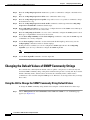
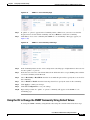
Changing the Default Values of SNMP Community Strings, page 4-40
•
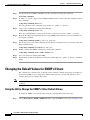
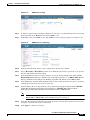
Changing the Default Values for SNMP v3 Users, page 4-42
•
Configuring Aggressive Load Balancing, page 4-44
•
Configuring Band Selection, page 4-48
•
Configuring Fast SSID Changing, page 4-51
•
Enabling 802.3X Flow Control, page 4-51
•
Configuring 802.3 Bridging, page 4-52
•
Configuring Multicast Mode, page 4-54
•
Configuring Client Roaming, page 4-59
•
Configuring IP-MAC Address Binding, page 4-64
•
Configuring Quality of Service, page 4-65
•
Configuring Voice and Video Parameters, page 4-72
•
Configuring Voice Prioritization Using Preferred Call Numbers, page 4-90
•
Configuring EDCA Parameters, page 4-91
•
Configuring the Cisco Discovery Protocol, page 4-94
•
Configuring Authentication for the Controller and NTP Server, page 4-105
•
Configuring RFID Tag Tracking, page 4-106
•
Configuring and Viewing Location Settings, page 4-110
•
Configuring the Supervisor 720 to Support the WiSM, page 4-118
•
Using the Wireless LAN Controller Network Module, page 4-119
Cisco Wireless LAN Controller Configuration Guide
OL-21524-02
4-1
Chapter 4
Configuring Controller Settings
Installing and Configuring Licenses
•
Resetting the Controller to Default Settings, page 4-120
Installing and Configuring Licenses
You can order Cisco 5500 Series Controllers with support for 12, 25, 50, 100, 250 or 500 access points
as the controller’s base capacity. You can add additional access point capacity through capacity adder
licenses available at 25, 50, 100 and 250 access point capacities. You can add the capacity adder licenses
to any base license in any combination to arrive at the maximum capacity of 500 access points. The base
and adder licenses are supported through both rehosting and RMAs.
Note
These controller platforms do not require licenses: Cisco 2100 and Cisco 4400 Series Controllers, Cisco
WiSMs, Controller Network Modules, and Catalyst 3750G Integrated Wireless LAN Controller
Switches.
Note
All features included in a Wireless LAN Controller Wplus license are now included in the base license;
this change is introduced in release 6.0.196.0. There are no changes to WCS BASE and PLUS licensing.
The base license supports the standard base software set and, for releases 6.0196.0 and later, the
premium software set is included as part of the base feature set, which includes this functionality:
•
Note
Datagram Transport Layer Security (DTLS) data encryption for added security across remote WAN
and LAN links. See the “Configuring Data Encryption” section on page 8-2 for more information
on data encryption.
The Availability of data DTLS for the 7.0.116.0 release is as follows:
Cisco 5500 Series Controller—The Cisco 5500 Series Controller will be available with two licensing
options: One with data DTLS capabilities and another image without data DTLS.
2500, WiSM2, WLC2—These platforms by default will not contain DTLS. To turn on data DTLS, you
must install a license. These platforms will have a single image with data DTLS turned off. To use data
DTLS you will need to have a license.
•
Support for OfficeExtend access points, which are used for secure mobile teleworking. See the
“OfficeExtend Access Points” section on page 8-69 for more information on OfficeExtend access
points.
•
Support for the 1130AG and 1240AG series indoor mesh access points, which dynamically establish
wireless connections in locations where it might be difficult to connect to the wired network. See
Chapter 9, “Controlling Mesh Access Points,” for more information on mesh access points.
All features included in a Wireless LAN Controller WPLUS license are now included in the base license;
this change is introduced in release 6.0.196.0. There are no changes to WCS BASE and PLUS licensing.
These WPlus license features are included in the base license:
•
OfficeExtend AP
•
Enterprise Mesh
•
CAPWAP Data Encryption
Cisco Wireless LAN Controller Configuration Guide
4-2
OL-21524-02
Chapter 4
Configuring Controller Settings
Installing and Configuring Licenses
The licensing change can affect features on your wireless LAN when you upgrade or downgrade
software releases, so you should be aware of these guidelines:
•
If you have a WPlus license and you upgrade from 6.0.x.x to 7.0.98.0, your license file contains both
Basic and WPlus license features. You won’t see any disruption in feature availability and operation.
•
If you have a WPlus license and you downgrade from 7.0.98.0 to 6.0.196.0 or 6.0.188 or 6.0.182,
your license file contains only base license, and you will lose all WPlus features.
•
If you have a base license and you downgrade from 6.0.196.0 to 6.0.188 or 6.0.182, when you
downgrade, you lose all WPlus features.
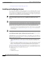
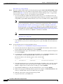
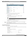
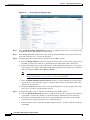
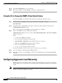
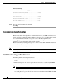
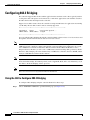
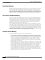
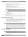
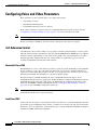
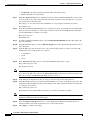
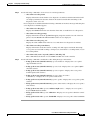
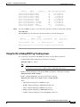
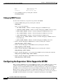
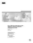
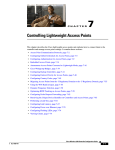
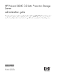
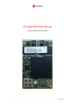
To view the controller trap log, choose Monitor and click View All under “Most Recent Traps” on the
controller GUI (see Figure 4-1).
Note
You can also view traps by using SNMP-based management tools.
Figure 4-1
Trap Logs Page
The ap-count licenses and their corresponding image-based licenses are installed together. The
controller keeps track of the licensed access point count and does not allow more than the number of
access points to associate to it.
The Cisco 5500 Series Controller is shipped with both permanent and evaluation base and base-ap-count
licenses. If desired, you can activate the evaluation licenses, which are designed for temporary use and
set to expire after 60 days.
Note
See the “Activating an AP-Count Evaluation License” section on page 4-14 for instructions on activating
an image-based evaluation license and the “Activating an AP-Count Evaluation License” section on
page 4-14 for instructions on activating an ap-count evaluation license.
No licensing steps are required after you receive your Cisco 5500 Series Controller because the licenses
you ordered are installed at the factory. In addition, licenses and product authorization keys (PAKs) are
preregistered to serial numbers. However, as your wireless network evolves, you might want to add
support for additional access points or upgrade from the standard software set to the base software set.
To do so, you need to obtain and install an upgrade license.
Obtaining an Upgrade or Capacity Adder License
A certificate with a product authorization key (PAK) is required before you can obtain an upgrade
license.
Cisco Wireless LAN Controller Configuration Guide
OL-21524-02
4-3
Chapter 4
Configuring Controller Settings
Installing and Configuring Licenses
You can use the capacity adder licenses to increase the number of access points supported by the
controller up to a maximum of 500 access points. The capacity adder licenses are available in access
point capacities of 10, 25, 50, 100 and 250 access points. You can add these licenses to any of the base
capacity licenses of 12, 25, 50, 100 and 250 access points.
For example, if your controller was initially ordered with support for 100 access points (base license
AIR-CT5508-100-K9), you could increase the capacity to 500 access points by purchasing a 250 access
point, 100 access point, and a 50 access point additive capacity license (LIC-CT5508-250A,
LIC-CT5508-100A, and LIC-CT5508-50A).
You can find more information on ordering capacity adder licenses at this URL:
http://www.cisco.com/en/US/products/ps10315/products_data_sheets_list.html
Note
If you skip any tiers when upgrading (for example, if you do not install the -25U and -50U licenses along
with the -100U), the license registration for the upgraded capacity fails.
FFor a single controller, you can order different upgrade licenses in one transaction (for example, -25U,
-50U, -100U, and -250U), for which you receive one PAK with one license. Then you have only one
license (instead of four) to install on your controller.
If you have multiple controllers and want to upgrade all of them, you can order multiple quantities of
each upgrade license in one transaction (for example, you can order 10 each of the -25U, -50U, -100U,
and -250 upgrade licenses), for which you receive one PAK with one license. You can continue to register
the PAK for multiple controllers until it is exhausted.
Base license SKUs for the Cisco 5500 Series Controllers are as follows:
•
AIR-CT5508-12-K9
•
AIR-CT5508-25-K9
•
AIR-CT5508-50-K9
•
AIR-CT5508-100-K9
•
AIR-CT5508-250-K9
•
AIR-CT5508-500-K9
Base license SKUs for the Cisco 2500 Series Controllers are as follows:
•
AIR-CT2504-5-K9
•
AIR-CT2504-15-K9
•
AIR-CT2504-25-K9
•
AIR-CT2504-50-K9
Base license SKUs for the Cisco WiSM2 Controllers are as follows:
•
WS-SVC-WISM2-1-K9—WiSM2 with 100 AP support.
•
WS-SVC-WISM2-3-K9—WiSM2 with 300 AP support
•
WS-SVC-WISM2-5-K9—WiSM2 with 500 AP support
Cisco Wireless LAN Controller Configuration Guide
4-4
OL-21524-02
Chapter 4
Configuring Controller Settings
Installing and Configuring Licenses
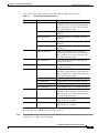
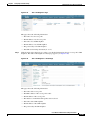
Table 4-1 lists the available adder licenses for the 5500 and 2500 Series Controllers:
Table 4-1
Available Capacity Adder Licenses
Type
Part Number
Description
e-mail
L-LIC-CT5508-UPG
Primary upgrade SKU: Pick any number or
combination of the following options under this
SKU to upgrade one or many controllers under
one product authorization key
L-LIC-CT5508-25A
25 AP Adder License for the 5508 Controller
(eDelivery)
L-LIC-CT5508-50A
50 AP Adder License for the 5508 Controller
(eDelivery)
L-LIC-CT5508-100A
100 AP Adder License for the 5508 Controller
(eDelivery)
L-LIC-CT5508-250A
250 AP Adder License for the 5508 Controller
(eDelivery)
L-LIC-CT2504-UPG
Primary upgrade SKU: Pick any number or
combination of the following options under this
SKU to upgrade one or many controllers under
one product authorization key
L-LIC-CT2504-5A
5 AP Adder License for Cisco 2504 Wireless
Controller (e-Delivery)
L-LIC-CT2504-25A
25 AP Adder License for Cisco 2504 Wireless
Controller (e-Delivery)
LIC-CT5508-UPG
Primary upgrade SKU: Pick any number or
combination of the following options under this
SKU, to upgrade one or many controllers under
one product authorization key
LIC-CT5508-25A
25 AP Adder License for the 5508 Controller
LIC-CT5508-50A
50 AP Adder License for the 5508 Controller
LIC-CT5508-100A
100 AP Adder License for the 5508 Controller
LIC-CT5508-250A
250 AP Adder License for the 5508 Controller
LIC-CT2504-UPG
Primary upgrade SKU: Pick any number or
combination of the following options under this
SKU to upgrade one or many controllers under
one product authorization key
LIC-CT2504-5A
5 AP Adder License for Cisco 2504 Controller
(Paper Certificate - US Mail)
LIC-CT2504-25A
25 AP Adder License for Cisco 2504 Controller
(Paper Certificate - US Mail)
paper
To obtain and register a PAK certificate, follow these steps:
Step 1
Order the PAK certificate for an upgrade license through your Cisco channel partner or your Cisco sales
representative, or order it online at this URL:
Cisco Wireless LAN Controller Configuration Guide
OL-21524-02
4-5
Chapter 4
Configuring Controller Settings
Installing and Configuring Licenses
http://www.cisco.com/go/ordering
Step 2
If you are ordering online, begin by choosing the primary upgrade SKU L-LIC-CT5508-UPG or LIC
CT5508-UPG. Then, choose any number of the following options to upgrade one or more controllers
under one PAK. Table 4-1 lists the capacity adder licenses available through e-mail or on paper:After
you receive the certificate, use one of two methods to register the PAK:
•
Cisco License Manager (CLM)—This method automates the process of obtaining licenses and
deploying them on Cisco devices. For deployments with more than five controllers, we recommend
using CLM to register PAKs and install licenses. You can also use CLM to rehost or RMA a license.
Note
You cannot use CLM to change the licensed feature set or activate an ap-count evaluation
license. To perform these operations, you must follow the instructions in the “Activating an
AP-Count Evaluation License” section on page 4-14 and the “Activating an AP-Count
Evaluation License” section on page 4-14. Because you can use CLM to perform all other
license operations, you can disregard the remaining licensing information in this chapter
except these two sections and the “Configuring the License Agent” section on page 4-23 if
you want your controller to use HTTP to communicate with CLM.
Note
You can download the CLM software and access user documentation at this URL:
http://www.cisco.com/go/clm
•
Step 3
Licensing portal—This alternative method enables you to manually obtain and install licenses on
your controller. If you want to use the licensing portal to register the PAK, follow the instructions
in Step 3.
Use the licensing portal to register the PAK as follows:
a.
Go to http://tools.cisco.com/SWIFT/Licensing/PrivateRegistrationServlet
b.
On the main Product License Registration page, enter the PAK mailed with the certificate in the
Product Authorization Key (PAK) text box and click Submit.
c.
On the Validate Features page, enter the number of licenses that you want to register in the Qty text
box and click Update.
d.
To determine the controller’s product ID and serial number, choose Controller > Inventory on the
controller GUI or enter the show license udi command on the controller CLI.
Information similar to the following appears on the controller CLI:
Device# PID
SN
UDI
------- -------------------- ----------------------- --------------------------------*0
AIR-CT5508-K9
FCW1308L030
AIR-CT5508-K9:FCW1308L030
e.
On the Designate Licensee page, enter the product ID and serial number of the controller on which
you plan to install the license, read and accept the conditions of the end-user license agreement
(EULA), complete the rest of the text boxes on this page, and click Submit.
f.
On the Finish and Submit page, verify that all information is correct and click Submit.
g.
When a message appears indicating that the registration is complete, click Download License. The
license is e-mailed within 1 hour to the address that you specified.
h.
When the e-mail arrives, follow the instructions provided.
i.
Copy the license file to your TFTP server.
Cisco Wireless LAN Controller Configuration Guide
4-6
OL-21524-02
Chapter 4
Configuring Controller Settings
Installing and Configuring Licenses
j.
Follow the instructions in the “Installing a License” section below to install the license on your
controller.
Installing a License
You can use the controller GUI or CLI to install a license on a Cisco 5500 Series Controller.
Using the GUI to Install a License
To install a license on the controller using the controller GUI, follow these steps:
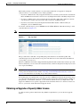
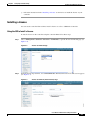
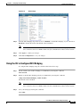
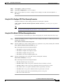
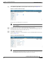
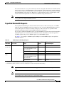
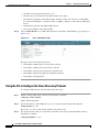
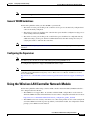
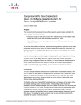
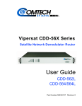
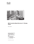
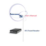
Step 1
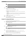
Choose Management > Software Activation > Commands to open the License Commands page (see
Figure 4-2).
Figure 4-2
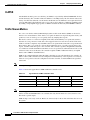
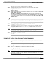
Step 2
License Commands Page
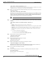
From the Action drop-down list, choose Install License. The Install License from a File section appears
(see Figure 4-3).
Figure 4-3
License Commands (Install License) Page
Cisco Wireless LAN Controller Configuration Guide
OL-21524-02
4-7
Chapter 4
Configuring Controller Settings
Installing and Configuring Licenses
Step 3
In the File Name to Install text box, enter the path to the license (*.lic) on the TFTP server.
Step 4
Click Install License. A message appears to show whether the license was installed successfully. If the
installation fails, the message provides the reason for the failure, such as the license is an existing
license, the path was not found, the license does not belong to this device, you do not have correct
permissions for the license, and so on.
Step 5
If the end-user license agreement (EULA) acceptance dialog box appears, read the agreement and click
Accept to accept the terms of the agreement.
Note
Step 6
Typically, you are prompted to accept the EULA for evaluation, extension, and rehost licenses.
The EULA is also required for permanent licenses, but it is accepted during license generation.
Save a backup copy of all installed licenses as follows:
a.
From the Action drop-down list, choose Save License.
b.
In the File Name to Save text box, enter the path on the TFTP server where you want the licenses to
be saved.
Note
c.
You cannot save evaluation licenses.
Click Save Licenses.
Step 7
Reboot the controller.
Step 8
Follow the instructions in the “Viewing Licenses” section on page 4-9 to see the status of the license that
you installed.
Step 9
If the desired license is not being used by the controller, follow the instructions in the “Activating an
AP-Count Evaluation License” section on page 4-14 or the “Activating an AP-Count Evaluation
License” section on page 4-14 to change the license that is used by the controller.
Using the CLI to Install a License
To install a license on the controller using the controller CLI, follow these steps:
Step 1
Install a license on the controller by entering this command:
license install url
where url is tftp://server_ip/path/filename.
Note
Step 2
To remove a license from the controller, enter the license clear license_name command. For
example, you might want to delete an expired evaluation license or any unused license. You
cannot delete unexpired evaluation licenses, the permanent base image license, or licenses that
are in use by the controller.
If you are prompted to accept the end-user license agreement (EULA), read and accept the terms of the
agreement.
Cisco Wireless LAN Controller Configuration Guide
4-8
OL-21524-02
Chapter 4
Configuring Controller Settings
Installing and Configuring Licenses
Note
Step 3
Typically, you are prompted to accept the EULA for evaluation, extension, and rehost licenses.
The EULA is also required for permanent licenses, but it is accepted during license generation.
Add comments to a license or delete comments from a license by entering this command:
license comment {add | delete} license_name comment_string
Step 4
Save a backup copy of all installed licenses by entering this command:
license save url
where url is tftp://server_ip/path/filename.
Step 5
Reboot the controller by entering this command:
reset system
Step 6
Follow the instructions in the “Viewing Licenses” section on page 4-9 to see the status of the license you
installed.
Step 7
If the desired license is not being used by the controller, follow the instructions in the “Activating an
AP-Count Evaluation License” section on page 4-14 or the “Activating an AP-Count Evaluation
License” section on page 4-14 to change the license that is used by the controller.
Viewing Licenses
This section describes how to view the licenses on the controller.
Using the GUI to View Licenses
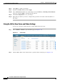
To view licenses on the controller using the controller GUI, follow these steps:
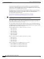
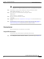
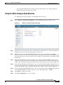
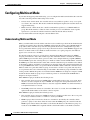
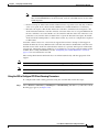
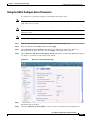
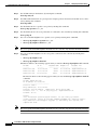
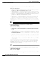
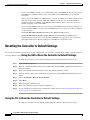
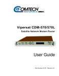
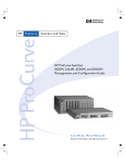
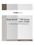
Step 1
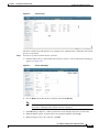
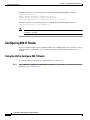
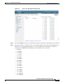
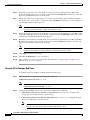
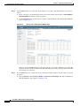
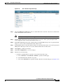
Choose Management > Software Activation > Licenses to open the Licenses page (see Figure 4-4).
Cisco Wireless LAN Controller Configuration Guide
OL-21524-02
4-9
Chapter 4
Configuring Controller Settings
Installing and Configuring Licenses
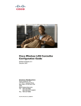
Figure 4-4
Licenses Page
This page lists all of the licenses installed on the controller. For each license, it shows the license type,
expiration, count (the maximum number of access points allowed for this license), priority (low,
medium, or high), and status (in use, not in use, inactive, or EULA not accepted).
Step 2
Note
Controller platforms do not support the status of “grace period” or “extension” as a license type.
The license status will always show “evaluation” even if a grace period or an extension
evaluation license is installed.
Note
If you ever want to remove a license from the controller, hover your cursor over the blue
drop-down arrow for the license and click Remove. For example, you might want to delete an
expired evaluation license or any unused license. You cannot delete unexpired evaluation
licenses, the permanent base image license, or licenses that are in use by the controller.
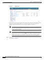
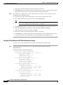
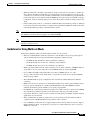
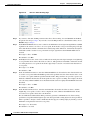
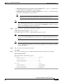
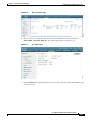
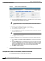
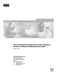
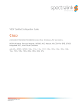
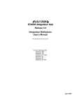
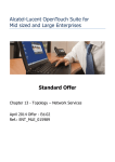
Click the link for the desired license to view more details for a particular license. The License Detail
page appears (see Figure 4-5).
Cisco Wireless LAN Controller Configuration Guide
4-10
OL-21524-02
Chapter 4
Configuring Controller Settings
Installing and Configuring Licenses
Figure 4-5
License Detail Page
This page shows the following additional information for the license:
•
The license type (permanent, evaluation, or extension)
•
The license version
•
The status of the license (in use, not in use, inactive, or EULA not accepted)
•
The length of time before the license expires
Note
Permanent licenses never expire.
•
Whether the license is a built-in license
•
The maximum number of access points allowed for this license
•
The number of access points currently using this license
Step 3
If you want to enter a comment for this license, type it in the Comment text box and click Apply.
Step 4
Click Save Configuration to save your changes.
Using the CLI to View Licenses
To view licenses on the controller, use these commands:
•
See the license level, license type, and number of access points licensed on the controller by entering
this command:
show sysinfo
Information similar to the following appears:
Manufacturer's Name..............................
Product Name.....................................
Product Version..................................
RTOS Version.....................................
Bootloader Version...............................
Emergency Image Version..........................
Build Type.......................................
System Name......................................
Cisco Systems Inc.
Cisco Controller
7.0
7.0
5.2
N/A
DATA + WPS
Cisco 69
Cisco Wireless LAN Controller Configuration Guide
OL-21524-02
4-11
Chapter 4
Configuring Controller Settings
Installing and Configuring Licenses
System Location.................................. na
System Contact................................... [email protected]
System ObjectID.................................. 1.3.6.1.4.1.14179.1.1.4.3
IP Address....................................... 10.10.10.10
System Up Time................................... 3 days 1 hrs 12 mins 42 secs
System Timezone Location.........................
CurrentBoot License Level..........................base
CurrentBoot License Type...........................Permanent
NextBoot License Level............................base
NextBoot License Type.............................Permanent
Operating Environment............................ Commercial (0 to 40 C)
Internal Temp Alarm Limits....................... 0 to 65 C
Internal Temperature............................. +40 C
State of 802.11b Network......................... Enabled
State of 802.11a Network......................... Enabled
Number of WLANs.................................. 4
Number of Active Clients......................... 0
Burned-in MAC Address............................ 00:1A:6D:DD:1E:40
Crypto Accelerator 1............................. Absent
Crypto Accelerator 2............................. Absent
Power Supply 1................................... Absent
Power Supply 2................................... Present, OK
Maximum number of APs supported.................. 12
Note
•
The Operating Environment and Internal temp Alarm Limits data are not displayed for Cisco
Flex 7500 Series Controllers.
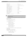
See a brief summary of all active licenses installed on the controller by entering this command:
show license summary
Information similar to the following appears:
Index 1 Feature: wplus
Period left: 0 minute 0 second
Index 2 Feature: wplus-ap-count
Period left: 0 minute 0 second
Index3 Feature: base
Period left: Life time
License Type: Permanent
License State: Active, In Use
License Count: Non-Counted
License Priority: Medium
Index 4 Feature: base-ap-count
Period left: 6 weeks, 4 days
License Type: Evaluation
License State: Active, In Use
License Count: 250/250/0
License Priority: High
•
See all of the licenses installed on the controller by entering this command:
show license all
Information similar to the following appears:
License Store: Primary License Storage
StoreIndex: 1 Feature: base
Version: 1.0
License Type: Permanent
License State: Active, Not in Use
License Count: Non-Counted
License Priority: Medium
Cisco Wireless LAN Controller Configuration Guide
4-12
OL-21524-02
Chapter 4
Configuring Controller Settings
Installing and Configuring Licenses
StoreIndex: 3 Feature: base-ap-count
Version: 1.0
License Type: Evaluation
License State: Active, In Use
Evaluation total period: 8 weeks 4 days
Evaluation period left: 8 weeks 3 days
License Count: 250/0/0
License Priority: High
•
See the details for a particular license by entering this command:
show license detail license_name
Information similar to the following appears:
•
Index:
1
Feature: base-ap-count
Version: 1.0
License Type: Permanent
License State: Active, Not in Use
License Count: 12/0/0
License Priority: Medium
Store Index: 0
Store Name: Primary License Storage
Index:
2
Feature: base-ap-count
Version: 1.0
License Type: Evaluation
License State: Inactive
Evaluation total period: 8 weeks 4 days
Evaluation period left: 8 weeks 4 days
License Count: 250/0/0
License Priority: Low
Store Index: 3
Store Name: Evaluation License Storage
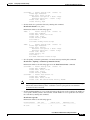
See all expiring, evaluation, permanent, or in-use licenses by entering this command:
show license {expiring | evaluation | permanent | in-use}
Information similar to the following appears for the show license in-use command:
StoreIndex: 2
License
License
License
License
StoreIndex: 3
License
License
License
Note
•
Feature: base-ap-count
Version: 1.0
Type: Permanent
State: Active, In Use
Count: 12/12/0
Priority: Medium
Feature: base Version: 1.0
Type: Permanent
State: Active, In Use
Count: Non-Counted License Priority: Medium
Controller platforms do not support the status of “grace period” or “extension” as a license type.
The license status will always show “evaluation” even if a grace period or an extension
evaluation license is installed.
See the maximum number of access points allowed for this license on the controller, the number of
access points currently joined to the controller, and the number of access points that can still join
the controller by entering this command:
show license capacity
Information similar to the following appears:
Licensed Feature
Max Count
Current Count
Remaining Count
----------------- --------------- ------------------- -------------------AP Count
250
4
246
Cisco Wireless LAN Controller Configuration Guide
OL-21524-02
4-13
Chapter 4
Configuring Controller Settings
Installing and Configuring Licenses
•
See statistics for all licenses on the controller by entering this command:
show license statistics
Information similar to the following appears:
Administrative statistics
Install success count:
Install failure count:
Install duplicate count:
Comment add count:
Comment delete count:
Clear count:
Save count:
Save cred count:
Client status
Request success count
Request failure count
Release count
Global Notify count
•
2
0
0
0
0
0
2
0
2
0
0
6
See a summary of license-enabled features by entering this command:
show license feature
Information similar to the following appears:
Feature name
base
base-ap-count
Enforcement
yes
yes
Evaluation
yes
yes
Clear Allowed
yes
yes
Enabled
yes
no
Activating an AP-Count Evaluation License
If you are considering upgrading to a license with a higher access point count, you can try an evaluation
license before upgrading to a permanent version of the license. For example, if you are using a permanent
license with a 50-access-point count and want to try an evaluation license with a 100-access-point count,
you can try out the evaluation license for 60 days.
AP-count evaluation licenses are set to low priority by default so that the controller uses the ap-count
permanent license. If you want to try an evaluation license with an increased access point count, you
must change its priority to high. If you no longer want to have this higher capacity, you can lower the
priority of the ap-count evaluation license, which forces the controller to use the permanent license.
Note
To prevent disruptions in operation, the controller does not switch licenses when an evaluation license
expires. You must reboot the controller in order to return to a permanent license. Following a reboot, the
controller defaults to the same feature set level as the expired evaluation license. If no permanent license
at the same feature set level is installed, the controller uses a permanent license at another level or an
unexpired evaluation license.
You can activate ap-count evaluation licenses using the controller GUI or CLI.
Using the GUI to Activate an AP-Count Evaluation License
To activate an ap-count evaluation license using the controller GUI, follow these steps:
Step 1
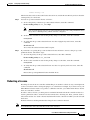
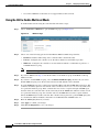
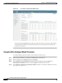
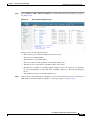
Choose Management > Software Activation > Licenses to open the Licenses page (see Figure 4-6).
Cisco Wireless LAN Controller Configuration Guide
4-14
OL-21524-02
Chapter 4
Configuring Controller Settings
Installing and Configuring Licenses
Figure 4-6
Licenses Page
The Status column shows which licenses are currently in use, and the Priority column shows the current
priority of each license.
Step 2
Activate an ap-count evaluation license as follows:
a.
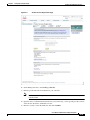
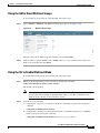
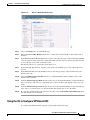
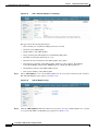
Click the link for the ap-count evaluation license that you want to activate. The License Detail page
appears (see Figure 4-7).
Figure 4-7
b.
License Detail Page
Choose High from the Priority drop-down list and click Set Priority.
Note
You can set the priority only for ap-count evaluation licenses. AP-count permanent licenses
always have a medium priority, which cannot be configured.
c.
Click OK when prompted to confirm your decision about changing the priority of the license.
d.
When the EULA appears, read the terms of the agreement and then click Accept.
e.
When prompted to reboot the controller, click OK.
Cisco Wireless LAN Controller Configuration Guide
OL-21524-02
4-15
Chapter 4
Configuring Controller Settings
Installing and Configuring Licenses
Step 3
f.
Reboot the controller in order for the priority change to take effect.
g.
Click Licenses to open the Licenses page and verify that the ap-count evaluation license now has a
high priority and is in use. You can use the evaluation license until it expires.
If you decide to stop using the ap-count evaluation license and want to revert to using an ap-count
permanent license, follow these steps:
a.
On the Licenses page, click the link for the ap-count evaluation license that is in use.
b.
Choose Low from the Priority drop-down list and click Set Priority.
Note
You can set the priority only for ap-count evaluation licenses. AP-count permanent licenses
always have a medium priority, which cannot be configured.
c.
Click OK when prompted to confirm your decision about changing the priority of the license.
d.
When the EULA appears, read the terms of the agreement and then click Accept.
e.
When prompted to reboot the controller, click OK.
f.
Reboot the controller in order for the priority change to take effect.
g.
Click Licenses to open the Licenses page and verify that the ap-count evaluation license now has a
low priority and is not in use. Instead, the ap-count permanent license should be in use.
Using the CLI to Activate an AP-Count Evaluation License
To activate an ap-count evaluation license using the controller CLI, follow these steps:
Step 1
See the current status of all the licenses on your controller by entering this command:
show license all
Information similar to the following appears:
License Store: Primary License Storage
StoreIndex: 0 Feature: base-ap-count
Version: 1.0
License Type: Permanent
License State: Active, In Use
License Count: 12/0/0
License Priority: Medium
StoreIndex: 1 Feature: base
Version: 1.0
License Type: Permanent
License State: Active, In Use
License Count: Non-Counted
License Priority: Medium
StoreIndex: 2 Feature: base
Version: 1.0
License Type: Evaluation
License State: Inactive
Evaluation total period: 8 weeks 4 days
Evaluation period left: 8 weeks 4 days
License Count: Non-Counted
License Priority: Low
StoreIndex: 3 Feature: base-ap-count
Version: 1.0
License Type: Evaluation
License State: Inactive
Evaluation total period: 8 weeks 4 days
Evaluation period left: 8 weeks 4 days
License Count: 250/0/0
Cisco Wireless LAN Controller Configuration Guide
4-16
OL-21524-02
Chapter 4
Configuring Controller Settings
Installing and Configuring Licenses
License Priority: Low
The License State text box shows the licenses that are in use, and the License Priority text box shows the
current priority of each license.
Step 2
Activate an ap-count evaluation license as follows:
a.
To raise the priority of the base-ap-count evaluation license, enter this command:
license modify priority license_name high
Note
b.
You can set the priority only for ap-count evaluation licenses. AP-count permanent licenses
always have a medium priority, which cannot be configured.
To reboot the controller in order for the priority change to take effect, enter this command:
reset system
c.
To verify that the ap-count evaluation license now has a high priority and is in use, enter this
command:
show license all
You can use the evaluation license until it expires.
Step 3
If you decide to stop using the ap-count evaluation license and want to revert to using an ap-count
permanent license, follow these steps:
a.
To lower the priority of the ap-count evaluation license, enter this command:
license modify priority license_name low
b.
To reboot the controller in order for the priority change to take effect, enter this command:
reset system
c.
To verify that the ap-count evaluation license now has a low priority and is not in use, enter this
command:
show license all
Instead, the ap-count permanent license should be in use.
Rehosting a License
Revoking a license from one controller and installing it on another is called rehosting. You might want
to rehost a license in order to change the purpose of a controller. For example, if you want to move your
OfficeExtend or indoor mesh access points to a different controller, you could transfer the base license
from one controller to another.
In order to rehost a license, you must generate credential information from the controller and use it to
obtain a permission ticket to revoke the license from the Cisco licensing site. Next, you must obtain a
rehost ticket and use it to obtain a license installation file for the controller on which you want to install
the license.
Evaluation licenses and the permanent base image license cannot be rehosted.
Note
A revoked license cannot be reinstalled on the same controller.
Cisco Wireless LAN Controller Configuration Guide
OL-21524-02
4-17
Chapter 4
Configuring Controller Settings
Installing and Configuring Licenses
Using the GUI to Rehost a License
To rehost a license using the controller GUI, follow these steps:
Step 1
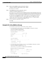
Choose Management > Software Activation > Commands to open the License Commands page.
Step 2
From the Action drop-down list, choose Rehost. The Revoke a License from the Device and Generate
Rehost Ticket area appears (see Figure 4-8).
Figure 4-8
License Commands (Rehost) Page
Step 3
In the File Name to Save Credentials text box, enter the path on the TFTP server where you want the
device credentials to be saved and click Save Credentials.
Step 4
To obtain a permission ticket to revoke the license, follow these steps:
a.
Click Cisco Licensing (https://tools.cisco.com/SWIFT/Licensing/PrivateRegistrationServlet). The
Product License Registration page appears (see Figure 4-9).
Cisco Wireless LAN Controller Configuration Guide
4-18
OL-21524-02
Chapter 4
Configuring Controller Settings
Installing and Configuring Licenses
Figure 4-9
Product License Registration Page
b.
Under Manage Licenses, click Look Up a License.
c.
Enter the product ID and serial number for your controller.
Note
To find the controller’s product ID and serial number, choose Controller > Inventory on the
controller GUI.
d.
Open the device credential information file that you saved in Step 3 and copy and paste the contents
of the file into the Device Credentials text box.
e.
Enter the security code in the blank box and click Continue.
Cisco Wireless LAN Controller Configuration Guide
OL-21524-02
4-19
Chapter 4
Configuring Controller Settings
Installing and Configuring Licenses
Step 5
Step 6
f.
Choose the licenses that you want to revoke from this controller and click Start License Transfer.
g.
On the Rehost Quantities page, enter the number of licenses that you want to revoke in the To Rehost
text box and click Continue.
h.
On the Designate Licensee page, enter the product ID and serial number of the controller for which
you plan to revoke the license, read and accept the conditions of the end-user license agreement
(EULA), complete the rest of the text boxes on this page, and click Continue.
i.
On the Review and Submit page, verify that all information is correct and click Submit.
j.
When a message appears indicating that the registration is complete, click Download Permission
Ticket. The rehost permission ticket is e-mailed within 1 hour to the address that you specified.
k.
After the e-mail arrives, copy the rehost permission ticket to your TFTP server.
Use the rehost permission ticket to revoke the license from this controller and generate a rehost ticket as
follows:
a.
In the Enter Saved Permission Ticket File Name text box, enter the TFTP path and filename (*.lic)
for the rehost permission ticket that you generated in Step 4.
b.
In the Rehost Ticket File Name text box, enter the TFTP path and filename (*.lic) for the ticket that
will be used to rehost this license on another controller.
c.
Click Generate Rehost Ticket.
d.
When the end-user license agreement (EULA) acceptance dialog box appears, read the agreement
and click Accept to accept the terms of the agreement.
Use the rehost ticket generated in Step 5 to obtain a license installation file, which can then be installed
on another controller as follows:
a.
Click Cisco Licensing.
b.
On the Product License Registration page, click Upload Rehost Ticket under Manage Licenses.
c.
On the Upload Ticket page, enter the rehost ticket that you generated in Step 5 in the Enter Rehost
Ticket text box and click Continue.
d.
On the Validate Features page, verify that the license information for your controller is correct, enter
the rehost quantity, and click Continue.
e.
On the Designate Licensee page, enter the product ID and serial number of the controller on which
you plan to use the license, read and accept the conditions of the end-user license agreement
(EULA), complete the rest of the text boxes on this page, and click Continue.
f.
On the Review and Submit page, verify that all information is correct and click Submit.
g.
When a message appears indicating that the registration is complete, click Download License. The
rehost license key is e-mailed within 1 hour to the address that you specified.
h.
After the e-mail arrives, copy the rehost license key to your TFTP server.
i.
Follow the instructions in the “Installing a License” section on page 4-7 to install this license on
another controller.
Using the CLI to Rehost a License
To rehost a license using the controller CLI, follow these steps:
Step 1
Save device credential information to a file by entering this command:
Cisco Wireless LAN Controller Configuration Guide
4-20
OL-21524-02
Chapter 4
Configuring Controller Settings
Installing and Configuring Licenses
license save credential url
where url is tftp://server_ip/path/filename.
Step 2
Obtain a permission ticket to revoke the license as follows:
a.
Go to https://tools.cisco.com/SWIFT/Licensing/PrivateRegistrationServlet. The Product License
Registration page appears (see Figure 4-9).
b.
Under Manage Licenses, click Look Up a License.
c.
Enter the product ID and serial number for your controller.
Note
Step 3
To find the controller’s product ID and serial number, enter the show license udi command
on the controller CLI.
d.
Open the device credential information file that you saved in Step 1 and copy and paste the contents
of the file into the Device Credentials text box.
e.
Enter the security code in the blank box and click Continue.
f.
Choose the licenses that you want to revoke from this controller and click Start License Transfer.
g.
On the Rehost Quantities page, enter the number of licenses that you want to revoke in the To Rehost
text box and click Continue.
h.
On the Designate Licensee page, enter the product ID and serial number of the controller for which
you plan to revoke the license, read and accept the conditions of the end-user license agreement
(EULA), complete the rest of the text boxes on this page, and click Continue.
i.
On the Review and Submit page, verify that all information is correct and click Submit.
j.
When a message appears indicating that the registration is complete, click Download Permission
Ticket. The rehost permission ticket is e-mailed within 1 hour to the address that you specified.
k.
After the e-mail arrives, copy the rehost permission ticket to your TFTP server.
Use the rehost permission ticket to revoke the license from this controller and generate a rehost ticket as
follows:
a.
To revoke the license from the controller, enter this command:
license revoke permission_ticket_url
where permission_ticket_url is tftp://server_ip/path/filename.
b.
To generate the rehost ticket, enter this command:
license revoke rehost rehost_ticket_url
where rehost_ticket_url is tftp://server_ip/path/filename.
c.
Step 4
If prompted, read and accept the terms of the end-user license agreement (EULA).
Use the rehost ticket generated in Step 3 to obtain a license installation file, which can then be installed
on another controller as follows:
a.
Go to https://tools.cisco.com/SWIFT/Licensing/PrivateRegistrationServlet.
b.
On the Product License Registration page, click Upload Rehost Ticket under Manage Licenses.
c.
On the Upload Ticket page, enter the rehost ticket that you generated in Step 3 in the Enter Rehost
Ticket text box and click Continue.
d.
On the Validate Features page, verify that the license information for your controller is correct, enter
the rehost quantity, and click Continue.
Cisco Wireless LAN Controller Configuration Guide
OL-21524-02
4-21
Chapter 4
Configuring Controller Settings
Installing and Configuring Licenses
e.
On the Designate Licensee page, enter the product ID and serial number of the controller on which
you plan to use the license, read and accept the conditions of the end-user license agreement
(EULA), complete the rest of the text boxes on this page, and click Continue.
f.
On the Review and Submit page, verify that all information is correct and click Submit.
g.
When a message appears indicating that the registration is complete, click Download License. The
rehost license key is e-mailed within 1 hour to the address that you specified.
h.
After the e-mail arrives, copy the rehost license key to your TFTP server.
i.
Follow the instructions in the “Installing a License” section on page 4-7 to install this license on
another controller.
Transferring Licenses to a Replacement Controller after an RMA
If you return a Cisco 5500 Series Controller to Cisco as part of the Return Material Authorization (RMA)
process, you must transfer that controller’s licenses within 60 days to a replacement controller that you
receive from Cisco.
Replacement controllers come preinstalled with the following licenses: permanent base and evaluation
base, base-ap-count. No other permanent licenses are installed. The SKU for replacement controllers is
AIR-CT5508-CA-K9.
Because licenses are registered to the serial number of a controller, you can use the licensing portal on
Cisco.com to request that the license from your returned controller be revoked and authorized for use on
the replacement controller. After your request is approved, you can install the old license on the
replacement controller. Before you begin, you need the product ID and serial number of both the returned
controller and the replacement controller. This information is included in your purchase records.
Note
The evaluation licenses on the replacement controller are designed for temporary use and expire after 60
days. To prevent disruptions in operation, the controller does not switch licenses when an evaluation
license expires. You must reboot the controller in order to return to a permanent license. If the evaluation
licenses expire before you transfer the permanent licenses from your defective controller to your
replacement controller, the replacement controller remains up and running using the permanent base
license, but access points are no longer able to join the controller.
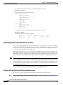
To transfer a license to a replacement controller after an RMA, follow these steps:
Step 1
Go to https://tools.cisco.com/SWIFT/Licensing/PrivateRegistrationServlet.
Step 2
On the main Product License Registration page, click Register for an RMA License under RMA
License Transfer.
Step 3
In the Select a Product drop-down list, choose Cisco 5500 Series Wireless Controllers.
Step 4
Enter the security code in the blank box and click Go to RMA Portal.
Step 5
On the RMA License Transfer page, enter the product ID and serial number of the controller that you
returned and your RMA service contract number, and click Continue.
Step 6
On the Validate Features page, verify that the license information for your controller is correct, and click
Continue.
Step 7
On the Designate Licensee page, enter the product ID and serial number of the replacement controller.
Cisco Wireless LAN Controller Configuration Guide
4-22
OL-21524-02
Chapter 4
Configuring Controller Settings
Installing and Configuring Licenses
Step 8
Read and accept the conditions of the end-user license agreement (EULA), complete the rest of the text
boxes on this page, and click Submit.
Step 9
On the Review and Submit page, verify that all information is correct and click Submit. A message
appears indicating that your registration request has been submitted, and you will receive an e-mail that
contains your RMA request ID.
Step 10
Select the status of your RMA registration request by following the instructions in the e-mail.
Step 11
After you receive another e-mail notifying you that your RMA registration request is approved (usually
within 1 hour), follow the instructions in the “Installing a License” section on page 4-7 to install the
license on the replacement controller.
Configuring the License Agent
If your network contains various Cisco-licensed devices, you might want to consider using the Cisco
License Manager (CLM) to manage all of the licenses using a single application. CLM is a secure
client/server application that manages Cisco software licenses network wide.
The license agent is an interface module that runs on the controller and mediates between CLM and the
controller’s licensing infrastructure. CLM can communicate with the controller using various channels,
such as HTTP, Telnet, and so on. If you want to use HTTP as the communication method, you must
enable the license agent on the controller.
The license agent receives requests from CLM and translates them into license commands. It also sends
notifications to CLM. It uses XML messages over HTTP or HTTPS to receive the requests and send the
notifications. For example, CLM sends a license install command, and the agent notifies CLM after the
license expires.
Note
You can download the CLM software and access user documentation at this URL:
http://www.cisco.com/go/clm
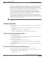
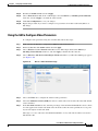
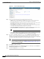
Using the GUI to Configure the License Agent
To configure the license agent on the controller using the controller GUI, follow these steps:
Step 1
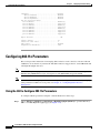
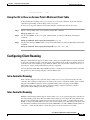
Choose Management > Software Activation > License Agent to open the License Agent Configuration
page (see Figure 4-10).
Cisco Wireless LAN Controller Configuration Guide
OL-21524-02
4-23
Chapter 4
Configuring Controller Settings
Installing and Configuring Licenses
Figure 4-10
License Agent Configuration Page
Step 2
Select the Enable Default Authentication check box to enable the license agent, or leave it unselected
to disable this feature. The default value is unselected.
Step 3
In the Maximum Number of Sessions text box, enter the maximum number of sessions for the license
agent. The valid range is 1 to 25 sessions (inclusive).
Step 4
Configure the license agent to listen for requests from the CLM as follows:
a.
Select the Enable Listener check box to enable the license agent to receive license requests from
the CLM, or unselect this check box to disable this feature. The default value is unselected.
b.
In the Listener Message Processing URL text box, enter the URL where the license agent receives
license requests (for example, http://209.165.201.30/licenseAgent/custom). The Protocol parameter
indicates whether the URL requires HTTP or HTTPS.
Note
Step 5
You can specify the protocol to use on the HTTP Configuration page. See the “Enabling Web
and Secure Web Modes” section on page 2-18 for more information.
c.
Select the Enable Authentication for Listener check box to enable authentication for the license
agent when it is receiving license requests, or unselect this check box to disable this feature. The
default value is unselected.
d.
In the Max HTTP Message Size text box, enter the maximum size for license requests. The valid
range is 0 to 9999 bytes, and the default value is 0.
Configure the license agent to send license notifications to the CLM as follows:
a.
Select the Enable Notification check box to enable the license agent to send license notifications
to the CLM, or unselect this check box to disable this feature. The default value is unselected.
b.
In the URL to Send the Notifications text box, enter the URL where the license agent sends the
notifications (for example, http://www.cisco.com/license/notify).
c.
In the User Name text box, enter the username required in order to view the notification messages
at this URL.
Cisco Wireless LAN Controller Configuration Guide
4-24
OL-21524-02
Chapter 4
Configuring Controller Settings
Installing and Configuring Licenses
d.
In the Password and Confirm Password text boxes, enter the password required in order to view the
notification messages at this URL.
Step 6
Click Apply to commit your changes.
Step 7
Click Save Configuration to save your changes.
Using the CLI to Configure the License Agent
To configure the license agent on the controller using the controller CLI, follow these steps:
Step 1
Step 2
Enable the license agent by entering one of these commands:
•
config license agent default authenticate—Enables the license agent default listener with
authentication.
•
config license agent default authenticate none—Enables the license agent default listener without
authentication.
Note
To disable the license agent default listener, enter the config license agent default disable
command. The default value is disabled.
Specify the maximum number of sessions for the license agent by entering this command:
config license agent max-sessions sessions
The valid range for the sessions parameter is 1 to 25 (inclusive), and the default value is 9.
Step 3
Enable the license agent to receive license requests from the CLM and to specify the URL where the
license agent receives the requests by entering this command:
config license agent listener http {plaintext | encrypt} url authenticate [none] [max-message size]
[acl acl]
The valid range for the size parameter is 0 to 65535 bytes, and the default value is 0.
Note
Step 4
To prevent the license agent from receiving license requests from the CLM, enter the config
license agent listener http disable command. The default value is disabled.
Configure the license agent to send license notifications to the CLM and to specify the URL where the
license agent sends the notifications by entering this command:
config license agent notify url username password
Note
Step 5
To prevent the license agent from sending license notifications to the CLM, enter the config
license agent notify disable username password command. The default value is disabled.
Save your changes by entering this command:
save config
Step 6
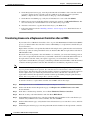
See statistics for the license agent’s counters or sessions by entering this command:
show license agent {counters | sessions}
Cisco Wireless LAN Controller Configuration Guide
OL-21524-02
4-25
Chapter 4
Configuring Controller Settings
Configuring 802.11 Bands
Information similar to the following appears for the show license agent counters command:
License Agent Counters
Request Messages Received:10: Messages with Errors:1
Request Operations Received:9: Operations with Errors:0
Notification Messages Sent:12: Transmission Errors:0: Soap Errors:0
Information similar to the following appears for the show license agent sessions command:
License Agent Sessions: 1 open, maximum is 9
Note
To clear the license agent’s counter or session statistics, enter the clear license agent {counters
| sessions} command.
Configuring 802.11 Bands
You can configure the 802.11b/g/n (2.4-GHz) and 802.11a/n (5-GHz) bands for the controller to comply
with the regulatory requirements in your country. By default, both 802.11b/g/n and 802.11a/n are
enabled.
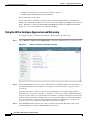
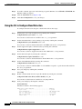
Using the GUI to Configure 802.11 Bands
To configure 802.11 bands using the controller GUI, follow these steps:
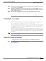
Step 1
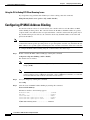
Choose Wireless > 802.11a/n or 802.11b/g/n > Network to open the 802.11a (or 802.11b/g) Global
Parameters page (see Figure 4-11).
Cisco Wireless LAN Controller Configuration Guide
4-26
OL-21524-02
Chapter 4
Configuring Controller Settings
Configuring 802.11 Bands
Figure 4-11
802.11a Global Parameters Page
Step 2
Select the 802.11a (or 802.11b/g) Network Status check box to enable the 802.11a or 802.11b/g band.
To disable the band, unselect the check box. The default value is enabled. You can enable both the
802.11a and 802.11b/g bands.
Step 3
If you enabled the 802.11b/g band in Step 2, select the 802.11g Support check box if you want to enable
802.11g network support. The default value is enabled. If you disable this feature, the 802.11b band is
enabled without 802.11g support.
Step 4
Specify the rate at which the SSID is broadcast by the access point by entering a value between 100 and
600 milliseconds (inclusive) in the Beacon Period text box. The default value is 100 milliseconds.
Note
The beacon period in controllers is listed in terms of milliseconds. The beacon period can also be
measured in time units, where one time unit equals 1024 microseconds or 102.4 milliseconds. If a beacon
interval is listed as 100 milliseconds in a controller, it is only a rounded off value for 102.4 milliseconds.
Due to hardware limitation in certain radios, even though the beacon interval is, say 100 time units, it is
adjusted to 102 time units, which roughly equals 1044.48 milliseconds. When the beacon period is to be
represented in terms of time units, the value is adjusted to the nearest multiple of 17.
Step 5
Specify the size at which packets are fragmented by entering a value between 256 and 2346 bytes
(inclusive) in the Fragmentation Threshold text box. Enter a low number for areas where communication
is poor or where there is a great deal of radio interference.
Step 6
Make access points advertise their channel and transmit power level in beacons and probe responses.
Select the DTPC Support check box. Otherwise, unselect this check box. The default value is enabled.
Client devices using dynamic transmit power control (DTPC) receive the channel and power level
information from the access points and adjust their settings automatically. For example, a client device
used primarily in Japan could rely on DTPC to adjust its channel and power settings automatically when
it travels to Italy and joins a network there.
Cisco Wireless LAN Controller Configuration Guide
OL-21524-02
4-27
Chapter 4
Configuring Controller Settings
Configuring 802.11 Bands
Step 7
Note
On access points that run Cisco IOS software, this feature is called world mode.
Note
DTPC and 801.11h power constraint cannot be enabled simultaneously.
Use the Data Rates options to specify the rates at which data can be transmitted between the access point
and the client. These data rates are available:
•
802.11a—6, 9, 12, 18, 24, 36, 48, and 54 Mbps
•
802.11b/g—1, 2, 5.5, 6, 9, 11, 12, 18, 24, 36, 48, or 54 Mbps
For each data rate, choose one of these options:
•
Mandatory—Clients must support this data rate in order to associate to an access point on the
controller.
•
Supported—Any associated clients that support this data rate may communicate with the access
point using that rate. However, the clients are not required to be able to use this rate in order to
associate.
•
Disabled—The clients specify the data rates used for communication.
Step 8
Click Apply to commit your changes.
Step 9
Click Save Configuration to save your changes.
Using the CLI to Configure 802.11 Bands
To configure 802.11 bands using the controller CLI, follow these steps:
Step 1
Disable the 802.11a band by entering this command:
config 802.11a disable network
Note
Step 2
The 802.11a band must be disabled before you can configure the 802.11a network parameters in
this section.
Disable the 802.11b/g band by entering this command:
config 802.11b disable network
Note
Step 3
The 802.11b band must be disabled before you can configure the 802.11b network parameters
in this section.
Specify the rate at which the SSID is broadcast by the access point by entering this command:
config {802.11a | 802.11b} beaconperiod time_unit
where time_unit is the beacon interval in time units (TUs). One TU is 1024 microseconds. You can
configure the access point to send a beacon every 20 to 1000 milliseconds.
Step 4
Specify the size at which packets are fragmented by entering this command:
Cisco Wireless LAN Controller Configuration Guide
4-28
OL-21524-02
Chapter 4
Configuring Controller Settings
Configuring 802.11 Bands
config {802.11a | 802.11b} fragmentation threshold
where threshold is a value between 256 and 2346 bytes (inclusive). Specify a low number for areas where
communication is poor or where there is a great deal of radio interference.
Step 5
Make access points advertise their channel and transmit power level in beacons and probe responses by
entering this command:
config {802.11a | 802.11b} dtpc {enable | disable}
The default value is enabled. Client devices using dynamic transmit power control (DTPC) receive the
channel and power level information from the access points and adjust their settings automatically. For
example, a client device used primarily in Japan could rely on DTPC to adjust its channel and power
settings automatically when it travels to Italy and joins a network there.
On access points that run Cisco IOS software, this feature is called world mode.
Note
Step 6
Specify the rates at which data can be transmitted between the controller and the client by entering this
command:
config {802.11a | 802.11b} rate {disabled | mandatory | supported} rate
where
•
disabled—Clients specify the data rates used for communication.
•
mandatory—Clients support this data rate in order to associate to an access point on the controller.
•
supported—Any associated clients that support this data rate may communicate with the access
point using that rate. However, the clients are not required to be able to use this rate in order to
associate.
•
rate—The rate at which data is transmitted:
– 6, 9, 12, 18, 24, 36, 48, and 54 Mbps (802.11a)
– 1, 2, 5.5, 6, 9, 11, 12, 18, 24, 36, 48, or 54 Mbps (802.11b/g)
Step 7
Enable the 802.11a band by entering this command:
config 802.11a enable network
The default value is enabled.
Step 8
Enable the 802.11b band by entering this command:
config 802.11b enable network
The default value is enabled.
Step 9
Enable or disable 802.11g network support by entering this command:
config 802.11b 11gSupport {enable | disable}
The default value is enabled. You can use this command only if the 802.11b band is enabled. If you
disable this feature, the 802.11b band is enabled without 802.11g support.
Step 10
Save your changes by entering this command:
save config
Step 11
View the configuration settings for the 802.11a or 802.11b/g band by entering this command:
show {802.11a | 802.11b}
Information similar to the following appears:
802.11a Network............................... Enabled
Cisco Wireless LAN Controller Configuration Guide
OL-21524-02
4-29
Chapter 4
Configuring Controller Settings
Configuring 802.11n Parameters
11nSupport.................................... Enabled
802.11a Low Band........................... Enabled
802.11a Mid Band........................... Enabled
802.11a High Band.......................... Enabled
802.11a Operational Rates
802.11a 6M Rate.............................. Mandatory
802.11a 9M Rate.............................. Supported
802.11a 12M Rate............................. Mandatory
802.11a 18M Rate............................. Supported
802.11a 24M Rate............................. Mandatory
802.11a 36M Rate............................. Supported
802.11a 48M Rate............................. Supported
802.11a 54M Rate............................. Supported
...
Beacon Interval.................................. 100
...
Default Channel............................... 36
Default Tx Power Level........................ 1
DTPC Status................................... Enabled
Fragmentation Threshold....................... 2346
...
Configuring 802.11n Parameters
This section provides instructions for managing 802.11n devices such as the Cisco Aironet 1140 and
1250 Series Access Points on your network. The 802.11n devices support the 2.4- and 5-GHz bands and
offer high-throughput data rates.
Note
The 802.11n high-throughput rates are available on 1140, 1250, 1260, and 3500 series access points for
WLANs using WMM with no Layer 2 encryption or with WPA2/AES encryption enabled.
Note
For information on configuring radio resource management (RRM) parameters or statically assigning
radio parameters for 802.11n access points, see Chapter 13, “Configuring Radio Resource
Management.”
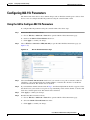
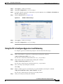
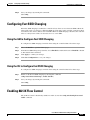
Using the GUI to Configure 802.11n Parameters
To configure 802.11n parameters using the controller GUI, follow these steps:
Step 1
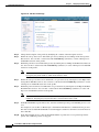
Choose Wireless > 802.11a/n or 802.11b/g/n > High Throughput (802.11n) to open the 802.11n (5
GHz or 2.4 GHz) High Throughput page (see Figure 4-12).
Cisco Wireless LAN Controller Configuration Guide
4-30
OL-21524-02
Chapter 4
Configuring Controller Settings
Configuring 802.11n Parameters
Figure 4-12
802.11n (2.4 GHz) High Throughput Page
Step 2
Select the 11n Mode check box to enable 802.11n support on the network. The default value is enabled.
Step 3
Select the check boxes of the desired rates to specify the modulation and coding scheme (MCS) rates at
which data can be transmitted between the access point and the client. These data rates, which are
calculated for a 20-MHz channel width using a short guard interval, are available:
•
0 (7 Mbps)
•
1 (14 Mbps)
•
2 (21 Mbps)
•
3 (29 Mbps)
•
4 (43 Mbps)
•
5 (58 Mbps)
•
6 (65 Mbps)
•
7 (72 Mbps)
•
8 (14 Mbps)
•
9 (29 Mbps)
•
10 (43 Mbps)
•
11 (58 Mbps)
•
12 (87 Mbps)
•
13 (116 Mbps)
•
14 (130 Mbps)
Cisco Wireless LAN Controller Configuration Guide
OL-21524-02
4-31
Chapter 4
Configuring Controller Settings
Configuring 802.11n Parameters
•
15 (144 Mbps)
Any associated clients that support the selected rates may communicate with the access point using those
rates. However, the clients are not required to be able to use this rate in order to associate. The MCS
settings determine the number of spatial streams, the modulation, the coding rate, and the data rate values
that are used.
Step 4
Click Apply to commit your changes.
Step 5
Use the 802.11n data rates that you configured by enabling WMM on the WLAN as follows:
Step 6
a.
Choose WLANs to open the WLANs page.
b.
Click the ID number of the WLAN for which you want to configure WMM mode.
c.
When the WLANs > Edit page appears, choose the QoS tab to open the WLANs > Edit (Qos) page.
d.
From the WMM Policy drop-down list, choose Required or Allowed to require or allow client
devices to use WMM. Devices that do not support WMM cannot join the WLAN.
e.
Click Apply to commit your changes.
Click Save Configuration to save your changes.
Note
To determine if an access point supports 802.11n, look at the 11n Supported text box on either
the 802.11a/n (or 802.11b/g/n) Cisco APs > Configure page or the 802.11a/n (or 802.11b/g/n)
AP Interfaces > Details page.
Using the CLI to Configure 802.11n Parameters
To configure 802.11n parameters using the controller CLI, follow these steps:
Step 1
Enable 802.11n support on the network by entering this command:
config {802.11a | 802.11b} 11nsupport {enable | disable}
Step 2
Specify the modulation and coding scheme (MCS) rates at which data can be transmitted between the
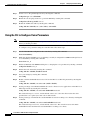
access point and the client by entering this command:
config {802.11a | 802.11b} 11nsupport mcs tx {0-15} {enable | disable}
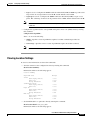
See the descriptions of the 0 through 15 MCS data rates in the “Using the GUI to Configure 802.11n
Parameters” section on page 4-30.
Step 3
Use the 802.11n data rates that you configured by enabling WMM on the WLAN as follows:
config wlan wmm required wlan_id
The required parameter requires client devices to use WMM. Devices that do not support WMM cannot
join the WLAN.
Step 4
Specify the aggregation method used for 802.11n packets as follows:
a.
Disable the network by entering this command:
config {802.11a | 802.11b} disable network
b.
Specify the aggregation method entering this command:
config {802.11a | 802.11b} 11nsupport a-mpdu tx priority {0-7 | all} {enable | disable}
Cisco Wireless LAN Controller Configuration Guide
4-32
OL-21524-02
Chapter 4
Configuring Controller Settings
Configuring 802.11n Parameters
Aggregation is the process of grouping packet data frames together rather than transmitting them
separately. Two aggregation methods are available: Aggregated MAC Protocol Data Unit
(A-MPDU) and Aggregated MAC Service Data Unit (A-MSDU). Both A-MPDU and A-MSDU are
performed in the software.
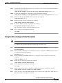
You can specify the aggregation method for various types of traffic from the access point to the
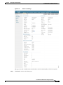
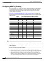
clients. Table 4-2 defines the priority levels (0-7) assigned per traffic type.
Table 4-2
Traffic Type Priority Levels
User Priority
Traffic Type
0
Best effort
1
Background
2
Spare
3
Excellent effort
4
Controlled load
5
Video, less than 100-ms latency and jitter
6
Voice, less than 10-ms latency and jitter
7
Network control
You can configure each priority level independently, or you can use the all parameter to configure
all of the priority levels at once. When you use the enable command, the traffic associated with that
priority level uses A-MPDU transmission. When you use the disable command, the traffic
associated with that priority level uses A-MSDU transmission. Configure the priority levels to match
the aggregation method used by the clients. By default, A-MPDU is enabled for priority level 0, 4
and 5 and the rest are disabled. By default, A-MPDU is enabled for all priorities except 6 and 7.
c.
Reenable the network by entering this command:
config {802.11a | 802.11b} enable network
Step 5
Save your changes by entering this command:
save config
Step 6
View the configuration settings for the 802.11a/n or 802.11b/g/n band by entering this command:
show {802.11a | 802.11b}
Information similar to the following appears:
802.11a Network............................... Enabled
11nSupport.................................... Enabled
802.11a Low Band........................... Enabled
802.11a Mid Band........................... Enabled
802.11a High Band.......................... Enabled
802.11a Operational Rates
802.11a 6M Rate.............................. Mandatory
802.11a 9M Rate.............................. Supported
802.11a 12M Rate............................. Mandatory
802.11a 18M Rate............................. Supported
802.11a 24M Rate............................. Mandatory
802.11a 36M Rate............................. Supported
802.11a 48M Rate............................. Supported
802.11a 54M Rate............................. Supported
802.11n MCS Settings:
MCS 0........................................ Supported
MCS 1...................................... Supported
Cisco Wireless LAN Controller Configuration Guide
OL-21524-02
4-33
Chapter 4
Configuring Controller Settings
Configuring 802.11n Parameters
MCS 2...................................... Supported
MCS 3...................................... Supported
MCS 4...................................... Supported
MCS 5...................................... Supported
MCS 6...................................... Supported
MCS 7...................................... Supported
MCS 8...................................... Supported
MCS 9...................................... Supported
MCS 10..................................... Supported
MCS 11..................................... Supported
MCS 12..................................... Supported
MCS 13..................................... Supported
MCS 14..................................... Supported
MCS 15........................................ Supported
802.11n Status:
A-MPDU Tx .................................. Enabled
Priority 0............................... Enabled
Priority 1............................... Enabled
Priority 2............................... Enabled
Priority 3............................... Enabled
Priority 4............................... Enabled
Priority 5............................... Disabled
Priority 6............................... Disabled
Priority 7............................... Enabled
A-MSDU Tx .................................. Enabled
Rifs Tx ..................................... Enabled
Guard Interval ............................. Short
Beacon Interval................................ 100
CF Pollable mandatory.......................... Disabled
CF Poll Request mandatory...................... Disabled
CFP Period......................................... 4
CFP Maximum Duration............................. 60
Default Channel.................................. 36
Default Tx Power Level........................... 1
DTPC Status...................................Enabled
Fragmentation Threshold....................... 2346
Long Retry Limit.................................. 4
Maximum Rx Life Time........................... 512
Max Tx MSDU Life Time............................ 512
Medium Occupancy Limit........................... 100
RTS Threshold.................................... 2347
Short Retry Limit................................ 7
TI Threshold..................................... -50
Traffic Stream Metrics Status.................... Enabled
Expedited BW Request Status...................... Disabled
EDCA profile type................................ default-wmm
Voice MAC optimization status.................... Disabled
Call Admission Control (CAC) configuration
Voice AC - Admission control (ACM)............ Enabled
Voice max RF bandwidth........................ 75
Voice reserved roaming bandwidth.............. 6
Voice load-based CAC mode..................... Disabled
Voice tspec inactivity timeout................ Disabled
Video AC - Admission control (ACM)............ Enabled
Voice Stream-Size............................. 84000
Voice Max-Streams............................. 2
Video max RF bandwidth........................ Infinite
Video reserved roaming bandwidth........... 0
Cisco Wireless LAN Controller Configuration Guide
4-34
OL-21524-02
Chapter 4
Configuring Controller Settings
Configuring 802.11h Parameters
Configuring 802.11h Parameters
802.11h informs client devices about channel changes and can limit the transmit power of those client
devices. You can configure the 802.11h parameters using the controller GUI or CLI.
Using the GUI to Configure 802.11h Parameters
To configure 802.11h parameters using the controller GUI, follow these steps:
Step 1
Step 2
Disable the 802.11a band as follows:
a.
Choose Wireless > 802.11a/n > Network to open the 802.11a Global Parameters page.
b.
Unselect the 802.11a Network Status check box.
c.
Click Apply to commit your change.
Choose Wireless > 802.11a/n > DFS (802.11h) to open the 802.11h Global Parameters page (see
Figure 4-13).
Figure 4-13
802.11h Global Parameters Page
Step 3
Select the Channel Announcement check box if you want the access point to announce when it is
switching to a new channel and the new channel number, or unselect this check box to disable the
channel announcement. The default value is disabled.
Step 4
If you enabled the channel announcement in Step 3, the Channel Quiet Mode check box appears. Select
this check box if you want the access point to stop transmitting on the current channel, or unselect this
check box to disable quiet mode. The default value is disabled.
Step 5
Click Apply to commit your changes.
Step 6
Reenable the 802.11a band as follows:
a.
Choose Wireless > 802.11a/n > Network to open the 802.11a Global Parameters page.
b.
Select the 802.11a Network Status check box.
c.
Click Apply to commit your change.
Cisco Wireless LAN Controller Configuration Guide
OL-21524-02
4-35
Chapter 4
Configuring Controller Settings
Configuring DHCP Proxy
Step 7
Click Save Configuration to save your changes.
Using the CLI to Configure 802.11h Parameters
To configure 802.11h parameters using the controller CLI, follow these steps:
Step 1
Disable the 802.11a network by entering this command:
config 802.11a disable network
Step 2
Enable or disable the access point to announce when it is switching to a new channel and the new channel
number by entering this command:
config 802.11h channelswitch {enable | disable} switch_mode
You can enter a 0 or 1 for the switch_mode parameter to specify whether transmissions are restricted until
the actual channel switch (0) or are not restricted (1). The default value is disabled.
Step 3
Configure a new channel using the 802.11h channel announcement by entering this command:
config 802.11h setchannel channel channel
Step 4
Configure the 802.11h power constraint value by entering this command:
config 802.11h powerconstraint value
The default value for the value parameter is 3 dB.
Step 5
Reenable the 802.11a network by entering this command:
config 802.11a enable network
Step 6
See the status of 802.11h parameters by entering this command:
show 802.11h
Information similar to the following appears:
Power Constraint................................. 0
Channel Switch................................... Disabled
Channel Switch Mode.............................. 0
Configuring DHCP Proxy
When DHCP proxy is enabled on the controller, the controller unicasts DHCP requests from the client
to the configured servers. Consequently, at least one DHCP server must be configured on either the
interface associated with the WLAN or the WLAN itself.
When DHCP proxy is disabled on the controller, those DHCP packets transmitted to and from the clients
are bridged by the controller without any modification to the IP portion of the packet. Packets received
from the client are removed from the CAPWAP tunnel and transmitted on the upstream VLAN. DHCP
packets directed to the client are received on the upstream VLAN, converted to 802.11, and transmitted
through a CAPWAP tunnel toward the client. As a result, the internal DHCP server cannot be used when
DHCP proxy is disabled. The ability to disable DHCP proxy allows organizations to use DHCP servers
that do not support Cisco’s native proxy mode of operation. It should be disabled only when required by
the existing infrastructure.
Cisco Wireless LAN Controller Configuration Guide
4-36
OL-21524-02
Chapter 4
Configuring Controller Settings
Configuring DHCP Proxy
You can use the controller GUI or CLI to enable or disable DHCP proxy on a global basis, rather than
on a WLAN basis. DHCP proxy is enabled by default.
Note
DHCP proxy must be enabled in order for DHCP option 82 to operate correctly. See the “Configuring
DHCP” section on page 7-10 for information on DHCP option 82.
Note
All controllers that will communicate must have the same DHCP proxy setting.
Note
See Chapter 7, “Configuring WLANs,” for information on configuring DHCP servers.
Using the GUI to Configure DHCP Proxy
To configure DHCP proxy using the controller GUI, follow these steps:
Step 1
Choose Controller > Advanced > DHCP to open the DHCP Parameters page (see Figure 4-14).
Figure 4-14
DHCP Parameters Page
Step 2
Select the Enable DHCP Proxy check box to enable DHCP proxy on a global basis. Otherwise, unselect
the check box. The default value is selected.
Step 3
Click Apply to commit your changes.
Step 4
Click Save Configuration to save your changes.
Using the CLI to Configure DHCP Proxy
To configure DHCP proxy using the controller CLI, follow these steps:
Step 1
Enable or disable DHCP proxy by entering this command:
config dhcp proxy {enable | disable}
Step 2
View the DHCP proxy configuration by entering this command:
show dhcp proxy
Information similar to the following appears:
Cisco Wireless LAN Controller Configuration Guide
OL-21524-02
4-37
Chapter 4
Configuring Controller Settings
Configuring Administrator Usernames and Passwords
DHCP Proxy Behavior: enabled
Using the GUI to Configure a DHCP Timeout
To configure a DHCP timeout using the controller GUI, follow these steps:
Step 1
Choose Controller > Advanced > DHCP to open the DHCP Parameters page.
Step 2
Select the DHCP Timeout (5 - 120 seconds) check box to enable a DHCP timeout on a global basis.
Otherwise, unselect the check box. The valid range is 5 through 120 seconds.
Step 3
Click Apply to commit your changes.
Step 4
Click Save Configuration to save your changes.
Using the CLI to Configure DHCP Timeout
To configure a DHCP timeout using the controller CLI, use the following command:
config dhcp timeout seconds
Configuring Administrator Usernames and Passwords
You can configure administrator usernames and passwords to prevent unauthorized users from
reconfiguring the controller and viewing configuration information. This section provides instructions
for initial configuration and for password recovery.
Configuring Usernames and Passwords
To configure administrator usernames and passwords using the controller CLI, follow these steps:
Step 1
Configure a username and password by entering one of these commands:
•
config mgmtuser add username password read-write—Creates a username-password pair with
read-write privileges.
•
config mgmtuser add username password read-only—Creates a username-password pair with
read-only privileges.
Usernames and passwords are case-sensitive and can contain up to 24 ASCII characters. Usernames and
passwords cannot contain spaces.
Note
Step 2
If you ever need to change the password for an existing username, enter the
config mgmtuser password username new_password command.
List the configured users by entering this command:
Cisco Wireless LAN Controller Configuration Guide
4-38
OL-21524-02
Chapter 4
Configuring Controller Settings
Configuring SNMP
show mgmtuser
Restoring Passwords
To configure a new username and password at boot-up using the controller CLI, follow these steps:
Step 1
After the controller boots up, enter Restore-Password at the User prompt.
Note
For security reasons, the text that you enter does not appear on the controller console.
Step 2
At the Enter User Name prompt, enter a new username.
Step 3
At the Enter Password prompt, enter a new password.
Step 4
At the Re-enter Password prompt, reenter the new password. The controller validates and stores your
entries in the database.
Step 5
When the User prompt reappears, enter your new username.
Step 6
When the Password prompt appears, enter your new password. The controller logs you in with your new
username and password.
Configuring SNMP
To configure SNMP using the controller CLI, follow these steps:
Step 1
Enter the config snmp community create name command to create an SNMP community name.
Step 2
Enter the config snmp community delete name command to delete an SNMP community name.
Step 3
Enter the config snmp community accessmode ro name command to configure an SNMP community
name with read-only privileges. Enter config snmp community accessmode rw name to configure an
SNMP community name with read-write privileges.
Step 4
Enter the config snmp community ipaddr ip-address ip-mask name command to configure an IP
address and subnet mask for an SNMP community.
Step 5
Note
This command behaves like an SNMP access list. It specifies the IP address from which the
device accepts SNMP packets with the associated community. The requesting entity’s IP address
is ANDed with the subnet mask before being compared to the IP address. If the subnet mask is
set to 0.0.0.0, an IP address of 0.0.0.0 matches to all IP addresses. The default value is 0.0.0.0.
Note
The controller can use only one IP address range to manage an SNMP community.
Enter the config snmp community mode enable command to enable a community name. Enter the
config snmp community mode disable command to disable a community name.
Cisco Wireless LAN Controller Configuration Guide
OL-21524-02
4-39
Chapter 4
Configuring Controller Settings
Changing the Default Values of SNMP Community Strings
Step 6
Enter the config snmp trapreceiver create name ip-address command to configure a destination for a
trap.
Step 7
Enter the config snmp trapreceiver delete name command to delete a trap.
Step 8
Enter the config snmp trapreceiver ipaddr old-ip-address name new-ip-address command to change
the destination for a trap.
Step 9
Enter the config snmp trapreceiver mode enable command to enable traps. Enter the config snmp
trapreceiver mode disable command to disable traps.
Step 10
Enter config snmp syscontact syscontact-name to configure the name of the SNMP contact. Enter up to
31 alphanumeric characters for the contact name.
Step 11
Enter the config snmp syslocation syslocation-name command to configure the SNMP system location.
Enter up to 31 alphanumeric characters for the location.
Step 12
Use the show snmpcommunity and the show snmptrap commands to verify that the SNMP traps and
communities are correctly configured.
Step 13
Use the show trapflags command to see the enabled and disabled trapflags. If necessary, use the
config trapflags command to enable or disable trapflags.
Step 14
Starting in release 7.0.116.0, you can also configure the SNMP engine ID. Use the config snmp
engineID engine-id-string command to configure the SNMP engine ID.
Note
Step 15
The engine ID string can be a maximum of 24 characters.
Use the show engineID command to view the engine ID.
Changing the Default Values of SNMP Community Strings
The controller has commonly known default values of “public” and “private” for the read-only and
read-write SNMP community strings. Using these standard values presents a security risk. If you use the
default community names, and since these are known, the community names could be used to
communicate to the controller using the SNMP protocol. Therefore, we strongly advise that you change
these values.
Using the GUI to Change the SNMP Community String Default Values
To change the SNMP community string default values using the controller GUI, follow these steps:
Step 1
Choose Management and then Communities under SNMP. The SNMP v1 / v2c Community page
appears (see Figure 4-15).
Cisco Wireless LAN Controller Configuration Guide
4-40
OL-21524-02
Chapter 4
Configuring Controller Settings
Changing the Default Values of SNMP Community Strings
Figure 4-15
SNMP v1 / v2c Community Page
Step 2
If “public” or “private” appears in the Community Name column, hover your cursor over the blue
drop-down arrow for the desired community and choose Remove to delete this community.
Step 3
Click New to create a new community. The SNMP v1 / v2c Community > New page appears (see
Figure 4-16).
Figure 4-16
SNMP v1 / v2c Community > New Page
Step 4
In the Community Name text box, enter a unique name containing up to 16 alphanumeric characters. Do
not enter “public” or “private.”
Step 5
In the next two text boxes, enter the IP address from which this device accepts SNMP packets with the
associated community and the IP mask.
Step 6
Choose Read Only or Read/Write from the Access Mode drop-down list to specify the access level for
this community.
Step 7
Choose Enable or Disable from the Status drop-down list to specify the status of this community.
Step 8
Click Apply to commit your changes.
Step 9
Click Save Configuration to save your settings.
Step 10
Repeat this procedure if a “public” or “private” community still appears on the SNMP v1 / v2c
Community page.
Using the CLI to Change the SNMP Community String Default Values
To change the SNMP community string default values using the controller CLI, follow these steps:
Cisco Wireless LAN Controller Configuration Guide
OL-21524-02
4-41
Chapter 4
Configuring Controller Settings
Changing the Default Values for SNMP v3 Users
Step 1
See the current list of SNMP communities for this controller by entering this command:
show snmp community
Step 2
If “public” or “private” appears in the SNMP Community Name column, enter this command to delete
this community:
config snmp community delete name
The name parameter is the community name (in this case, “public” or “private”).
Step 3
Create a new community by entering this command:
config snmp community create name
Enter up to 16 alphanumeric characters for the name parameter. Do not enter “public” or “private.”
Step 4
Enter the IP address from which this device accepts SNMP packets with the associated community by
entering this command:
config snmp community ipaddr ip_address ip_mask name
Step 5
Specify the access level for this community by entering this command, where ro is read-only mode and
rw is read/write mode:
config snmp community accessmode {ro | rw} name
Step 6
Enable or disable this SNMP community by entering this command:
config snmp community mode {enable | disable} name
Step 7
Save your changes by entering save config.
Step 8
Repeat this procedure if you still need to change the default values for a “public” or “private” community
string.
Changing the Default Values for SNMP v3 Users
The controller uses a default value of “default” for the username, authentication password, and privacy
password for SNMP v3 users. Using these standard values presents a security risk. Therefore, Cisco
strongly advises that you change these values.
Note
SNMP v3 is time sensitive. Make sure that you have configured the correct time and time zone on your
controller.
Using the GUI to Change the SNMP v3 User Default Values
To change the SNMP v3 user default values using the controller GUI, follow these steps:
Step 1
Choose Management > SNMP > SNMP V3 Users to open the SNMP V3 Users page (see Figure 4-17).
Cisco Wireless LAN Controller Configuration Guide
4-42
OL-21524-02
Chapter 4
Configuring Controller Settings
Changing the Default Values for SNMP v3 Users
Figure 4-17
SNMP V3 Users Page
Step 2
If “default” appears in the User Name column, hover your cursor over the blue drop-down arrow for the
desired user and choose Remove to delete this SNMP v3 user.
Step 3
Click New to add a new SNMP v3 user. The SNMP V3 Users > New page appears (see Figure 4-18).
Figure 4-18
SNMP V3 Users > New Page
Step 4
In the User Profile Name text box, enter a unique name. Do not enter “default.”
Step 5
Choose Read Only or Read Write from the Access Mode drop-down list to specify the access level for
this user. The default value is Read Only.
Step 6
From the Authentication Protocol drop-down list, choose the desired authentication method: None,
HMAC-MD5 (Hashed Message Authentication Coding-Message Digest 5), or HMAC-SHA (Hashed
Message Authentication Coding-Secure Hashing Algorithm). The default value is HMAC-SHA.
Step 7
In the Auth Password and Confirm Auth Password text boxes, enter the shared secret key to be used for
authentication. You must enter at least 12 characters.
Step 8
From the Privacy Protocol drop-down list, choose the desired encryption method: None, CBC-DES
(Cipher Block Chaining-Digital Encryption Standard), or CFB-AES-128 (Cipher Feedback
Mode-Advanced Encryption Standard-128). The default value is CFB-AES-128.
Note
In order to configure CBC-DES or CFB-AES-128 encryption, you must have selected either
HMAC-MD5 or HMAC-SHA as the authentication protocol in Step 6.
Step 9
In the Priv Password and Confirm Priv Password text boxes, enter the shared secret key to be used for
encryption. You must enter at least 12 characters.
Step 10
Click Apply to commit your changes.
Cisco Wireless LAN Controller Configuration Guide
OL-21524-02
4-43
Chapter 4
Configuring Controller Settings
Configuring Aggressive Load Balancing
Step 11
Click Save Configuration to save your settings.
Step 12
Reboot the controller so that the SNMP v3 user that you added takes effect.
Using the CLI to Change the SNMP v3 User Default Values
To change the SNMP v3 user default values using the controller CLI, follow these steps:
Step 1
See the current list of SNMP v3 users for this controller by entering this command:
show snmpv3user
Step 2
If “default” appears in the SNMP v3 User Name column, enter this command to delete this user:
config snmp v3user delete username
The username parameter is the SNMP v3 username (in this case, “default”).
Step 3
Create a new SNMP v3 user by entering this command:
config snmp v3user create username {ro | rw} {none | hmacmd5 | hmacsha} {none | des | aescfb128}
auth_key encrypt_key
where
•
username is the SNMP v3 username.
•
ro is read-only mode and rw is read-write mode.
•
none, hmacmd5, and hmacsha are the authentication protocol options.
•
none, des, and aescfb128 are the privacy protocol options.
•
auth_key is the authentication shared secret key.
•
encrypt_key is the encryption shared secret key.
Do not enter “default” for the username, auth_key, and encrypt_key parameters.
Step 4
Save your changes by entering the save config command.
Step 5
Reboot the controller so that the SNMP v3 user that you added takes effect by entering reset system
command.
Configuring Aggressive Load Balancing
Enabling aggressive load balancing on the controller allows lightweight access points to load balance
wireless clients across access points. You can enable aggressive load balancing using the controller GUI
or CLI.
Note
Clients are load balanced between access points on the same controller. Load balancing does not occur
between access points on different controllers.
Cisco Wireless LAN Controller Configuration Guide
4-44
OL-21524-02
Chapter 4
Configuring Controller Settings
Configuring Aggressive Load Balancing
When a wireless client attempts to associate to a lightweight access point, association response packets
are sent to the client with an 802.11 response packet including status code 17. This code indicates
whether the access point can accept any more associations. If the access point is too busy, the client
attempts to associate to a different access point in the area. The system determines if an access point is
relatively more busy than its neighbor access points that are also accessible to the client.
For example, if the number of clients on AP1 is more than the number of clients on AP2 plus the
load-balancing window, then AP1 is considered to be busier than AP2. When a client attempts to
associate to AP1, it receives an 802.11 response packet with status code 17, indicating that the access
point is busy, and the client attempts to associate to a different access point.
You can configure the controller to deny client associations up to 10 times (if a client attempted to
associate 11 times, it would be allowed to associate on the 11th try). You can also enable or disable load
balancing on a particular WLAN, which is useful if you want to disable load balancing for a select group
of clients (such as time-sensitive voice clients).
Note
Cisco Aironet 600 Series OfficeExtend and Hybrid-REAP access points do not support client load
balancing.
Client Association Limits
The maximum number of client associations that the access points can support is dependent upon the
following factors:
•
The maximum number of client associations differs for lightweight and autonomous Cisco IOS
access points.
•
There may be a limit per radio and an overall limit per AP.
•
AP hardware (the 16-MB APs have a lower limit than the 32-MB and higher APs).
Client Association Limits for Lightweight Access Points
The Per-AP limits are as follows:
•
For 16-MB APs, the limit is 128 clients per AP. This limit is applicable to 1100 and 1200 series APs.
•
For 32-MB and higher APs, there is no per-AP limit.
The per-radio limits are as follows:
•
For all Cisco IOS APs, the limit is 200 associations per radio.
•
For all 1000 and 1500 series APs, which are not supported beyond release 4.2, the limit is 250
associations per radio.
With 32-MB and higher lightweight Cisco IOS APs, with two radios, up to 200 + 200 = 400 associations
are supported.
Client Association Limits for Autonomous Cisco IOS Access Points
The client association limits for autonomous Cisco IOS access points are as follows:
The limit is around 80 to 127 clients per AP. This number varies depending on the following factors:
•
AP model (whether it is 16 MB or 32 MB or higher).
•
Cisco IOS version.
Cisco Wireless LAN Controller Configuration Guide
OL-21524-02
4-45
Chapter 4
Configuring Controller Settings
Configuring Aggressive Load Balancing
•
Hardware configuration (two radios use more memory than one).
•
Enabled features (WDS functionality in particular).
The per-radio limits are as follows:
The per-radio limit is about 200 associations. One association will likely hit the per-AP limit first.
Unlike Cisco Unified Wireless Network, autonomous Cisco IOS supports per-SSID/per-AP association
limits. This limit is configured using the max-associations CLI, under dot11 SSID. The maximum
number is 255 associations (which is also the default number).
Using the GUI to Configure Aggressive Load Balancing
To configure aggressive load balancing using the controller GUI, follow these steps:
Step 1
Choose Wireless > Advanced > Load Balancing to open the Load Balancing page (see Figure 4-19).
Figure 4-19
Step 2
Wireless > Advanced > Load Balancing Page
In the Client Window Size text box, enter a value between 1 and 20. The window size becomes part of
the algorithm that determines whether an access point is too heavily loaded to accept more client
associations:
load-balancing window + client associations on AP with highest load = load-balancing threshold
In the group of access points accessible to a client device, each access point has a different number of
client associations. The access point with the lowest number of clients has the lightest load. The client
window size plus the number of clients on the access point with the lightest load forms the threshold.
Access points with more client associations than this threshold is considered busy, and clients can
associate only to access points with client counts lower than the threshold.
Step 3
In the Maximum Denial Count text box, enter a value between 0 and 10. The denial count sets the
maximum number of association denials during load balancing.
Cisco Wireless LAN Controller Configuration Guide
4-46
OL-21524-02
Chapter 4
Configuring Controller Settings
Configuring Aggressive Load Balancing
Step 4
Click Apply to commit your changes.
Step 5
Click Save Configuration to save your changes.
Step 6
To enable or disable aggressive load balancing on specific WLANs, choose WLANs > WLAN ID. The
WLANs > Edit page appears.
Step 7
Click the Advanced tab (see Figure 4-20).
Figure 4-20
WLANs > Advanced Page
Step 8
Click Apply to commit your changes.
Step 9
Click Save Configuration to save your settings
Using the CLI to Configure Aggressive Load Balancing
To configure aggressive load balancing using the controller CLI, follow these steps:
Step 1
Set the client window for aggressive load balancing by entering this command:
config load-balancing window client_count
You can enter a value between 0 and 20 for the client_count parameter.
Step 2
Set the denial count for load balancing by entering this command:
config load-balancing denial denial_count
You can enter a value between 1 and 10 for the denial_count parameter.
Step 3
Save your changes by entering this command:
save config
Step 4
Enable or disable aggressive load balancing on specific WLANs by entering this command:
config wlan load-balance allow {enable | disable} wlan_ID
You can enter a value between 1 and 512 for wlan_ID parameter.
Step 5
Verify your settings by entering this command:
Cisco Wireless LAN Controller Configuration Guide
OL-21524-02
4-47
Chapter 4
Configuring Controller Settings
Configuring Band Selection
show load-balancing
Information similar to the following appears:
Aggressive Load Balancing........................ Enabled
Aggressive Load Balancing Window................. 1 clients
Aggressive Load Balancing Denial Count........... 3
Total Denied Count...............................
Total Denial Sent................................
Exceeded Denial Max Limit Count..................
None 5G Candidate Count..........................
None 2.4G Candidate Count........................
Step 6
Statistics
5 clients
10 messages
0 times
0 times
0 times
Save your changes by entering this command:
save config
Configuring Band Selection
Band selection enables client radios that are capable of dual-band (2.4- and 5-GHz) operation to move
to a less congested 5-GHz access point. The 2.4-GHz band is often congested. Clients on this band
typically experience interference from Bluetooth devices, microwave ovens, and cordless phones as well
as co-channel interference from other access points because of the 802.11b/g limit of three
nonoverlapping channels. To combat these sources of interference and improve overall network
performance, you can configure band selection on the controller.
Band selection works by regulating probe responses to clients. It makes 5-GHz channels more attractive
to clients by delaying probe responses to clients on 2.4-GHz channels.
Band selection is enabled globally by default.
Note
Band-selection enabled WLANs do not support time-sensitive applications like voice and video because
of roaming delays.
Guidelines for Using the Band Selection
Follow these guidelines when using band selection:
•
Band selection can be used only with Cisco Aironet 1140 and 1250 Series and the 3500 series access
points.
•
Band selection operates only on access points that are connected to a controller. A hybrid-REAP
access point without a controller connection does not perform band selection after a reboot.
Note
•
OEAP 600 Series access points do not support band select.
The band-selection algorithm directs dual-band clients only from the 2.4-GHz radio to the 5-GHz
radio of the same access point, and it only runs on an access point when both the 2.4-GHz and 5-GHz
radios are up and running.
Cisco Wireless LAN Controller Configuration Guide
4-48
OL-21524-02
Chapter 4
Configuring Controller Settings
Configuring Band Selection
•
You can enable both band selection and aggressive load balancing on the controller. They run
independently and do not impact one another.
Using the GUI to Configure Band Selection
To configure band selection using the controller GUI, follow these steps:
Step 1
Choose Wireless > Advanced > Band Select to open the Band Select page (see Figure 4-21).
Figure 4-21
Wireless > Advanced > Band Select Page
Step 2
In the Probe Cycle Count text box, enter a value between 1 and 10. The cycle count sets the number of
suppression cycles for a new client. The default cycle count is 2.
Step 3
In the Scan Cycle Period Threshold (milliseconds) text box, enter a value between 1 and 1000
milliseconds for the scan cycle period threshold. This setting determines the time threshold during which
new probe requests from a client come from a new scanning cycle. The default cycle threshold is 200
milliseconds.
Step 4
In the Age Out Suppression (seconds) text box, enter a value between 10 and 200 seconds. Age-out
suppression sets the expiration time for pruning previously known 802.11b/g clients. The default value
is 20 seconds. After this time elapses, clients become new and are subject to probe response suppression.
Step 5
In the Age Out Dual Band (seconds) text box, enter a value between 10 and 300 seconds. The age-out
period sets the expiration time for pruning previously known dual-band clients. The default value is 60
seconds. After this time elapses, clients become new and are subject to probe response suppression.
Step 6
In the Acceptable Client RSSI (dBm) text box, enter a value between –20 and –90 dBm. This parameter
sets the minimum RSSI for a client to respond to a probe. The default value is –80 dBm.
Step 7
Click Apply to commit your changes.
Step 8
Click Save Configuration to save your changes.
Cisco Wireless LAN Controller Configuration Guide
OL-21524-02
4-49
Chapter 4
Configuring Controller Settings
Configuring Band Selection
Step 9
To enable or disable aggressive load balancing on specific WLANs, choose WLANs > WLAN ID. The
WLANs > Edit page appears.
Step 10
Click the Advanced tab (see Figure 4-20).
Step 11
Click Save Configuration to save your changes.
Using the CLI to Configure Band Selection
To configure band selection using the controller CLI, follow these steps:
Step 1
Set the probe cycle count for band select by entering this command:
config band-select cycle-count cycle_count
You can enter a value between 1 and 10 for the cycle_count parameter.
Step 2
Set the time threshold for a new scanning cycle period by entering this command:
config band-select cycle-threshold milliseconds
You can enter a value for threshold between 1 and 1000 for the milliseconds parameter.
Step 3
Set the suppression expire to the band select by entering this command:
config band-select expire suppression seconds
You can enter a value for suppression between 10 to 200 for the seconds parameter.
Step 4
Set the dual band expire by entering this command:
config band-select expire dual-band seconds
You can enter a value for dual band between 10 and 300 for the seconds parameter.
Step 5
Set the client RSSI threshold by entering this command:
config band-select client-rssi client_rssi
You can enter a value for minimum dBm of a client RSSI to respond to a probe between 20 and 90 for
the client_rssi parameter.
Step 6
Save your changes by entering this command:
save config
Step 7
Enable or disable band selection on specific WLANs by entering this command:
config wlan band-select allow {enable | disable} wlan_ID
You can enter a value between 1 and 512 for wlan_ID parameter.
Step 8
Verify your settings by entering this command:
show band-select
Information similar to the following appears:
Band Select Probe Response.......................
Cycle Count...................................
Cycle Threshold...............................
Age Out Suppression...........................
Age Out Dual Band.............................
Client RSSI...................................
Enabled
3 cycles
300 milliseconds
20 seconds
20 seconds
-30 dBm
Cisco Wireless LAN Controller Configuration Guide
4-50
OL-21524-02
Chapter 4
Configuring Controller Settings
Configuring Fast SSID Changing
Step 9
Save your changes by entering this command:
save config
Configuring Fast SSID Changing
When fast SSID changing is enabled, the controller allows clients to move between SSIDs. When the
client sends a new association for a different SSID, the client entry in the controller connection table is
cleared before the client is added to the new SSID. When fast SSID changing is disabled, the controller
enforces a delay before clients are allowed to move to a new SSID.
Using the GUI to Configure Fast SSID Changing
To configure fast SSID changing for mobile clients using the controller GUI, follow these steps:
Step 1
Choose Controller to open the General page.
Step 2
From the Fast SSID Change drop-down list, choose Enabled to enable this feature or Disabled to disable
it. The default value is disabled.
Step 3
Click Apply to commit your changes.
Step 4
Click Save Configuration to save your changes.
Using the CLI to Configure Fast SSID Changing
To configure fast SSID changing for mobile clients using the controller CLI, follow these steps:
Step 1
Enable or disable fast SSID changing by entering this command:
config network fast-ssid-change {enable | disable}
Step 2
Save your changes by entering this command:
save config
Enabling 802.3X Flow Control
802.3X Flow Control is disabled by default. To enable it, enter the config switchconfig flowcontrol
enable command.
Cisco Wireless LAN Controller Configuration Guide
OL-21524-02
4-51
Chapter 4
Configuring Controller Settings
Configuring 802.3 Bridging
Configuring 802.3 Bridging
The controller supports 802.3 frames and the applications that use them, such as those typically used for
cash registers and cash register servers. However, to make these applications work with the controller,
the 802.3 frames must be bridged on the controller.
Support for raw 802.3 frames allows the controller to bridge non-IP frames for applications not running
over IP. Only this raw 802.3 frame format is currently supported:
+-------------------+---------------------+-----------------+------------------------+
| Destination
| Source
| Total packet | Payload .....
| MAC address | MAC address | length
|
+-------------------+----------------------+-----------------+-----------------------You can configure 802.3 bridging through the controller GUI in software release 4.1 or later releases and
through the controller CLI in software release 4.0 or later releases.
Note
In controller software release 5.2 or later releases, the software-based forwarding architecture for
2100-series-based controllers is being replaced with a new forwarding plane architecture. As a result,
Cisco 2100 Series Controller and the Cisco Wireless LAN Controller Network Module for Cisco
Integrated Services Routers (as well as Cisco 5500 Series Controllers) bridge 802.3 packets by default.
Therefore, 802.3 bridging can now be disabled only on 4400 series controllers, the Cisco WiSM, and the
Catalyst 3750G Wireless LAN Controller Switch.
Note
By default, Cisco 2100 Series Controllers that run software release 5.2 or later releases and Cisco 5500
Series Controllers bridge all non-IPv4 packets (such as AppleTalk, IPv6, and so on). If desired, you can
use ACLs to block the bridging of these protocols.
Note
You can also configure 802.3 bridging using the Cisco Wireless Control System (WCS). See the Cisco
Wireless Control System Configuration Guide for instructions.
Using the GUI to Configure 802.3 Bridging
To configure 802.3 bridging using the controller GUI, follow these steps:
Step 1
Choose Controller > General to open the General page (see Figure 4-22).
Cisco Wireless LAN Controller Configuration Guide
4-52
OL-21524-02
Chapter 4
Configuring Controller Settings
Configuring 802.3 Bridging
Figure 4-22
Step 2
General Page
From the 802.3 Bridging drop-down list, choose Enabled to enable 802.3 bridging on your controller or
Disabled to disable this feature. The default value is Disabled.
Note
In controller software release 5.2 or later releases, you can disable 802.3 bridging only for 4400
series controllers, the Cisco WiSM, and the Catalyst 3750G Wireless LAN Controller Switch.
Step 3
Click Apply to commit your changes.
Step 4
Click Save Configuration to save your changes.
Using the CLI to Configure 802.3 Bridging
To configure 802.3 bridging using the controller CLI, follow these steps:
Step 1
See the current status of 802.3 bridging for all WLANs by entering this command:
show network
Step 2
Enable or disable 802.3 bridging globally on all WLANs by entering this command:
config network 802.3-bridging {enable | disable}
The default value is disabled.
Note
Step 3
In controller software release 5.2 or later releases, you can disable 802.3 bridging only for 4400
series controllers, the Cisco WiSM, and the Catalyst 3750G Wireless LAN Controller Switch.
Save your settings by entering this command:
save config
Cisco Wireless LAN Controller Configuration Guide
OL-21524-02
4-53
Chapter 4
Configuring Controller Settings
Configuring Multicast Mode
Configuring Multicast Mode
If your network supports packet multicasting, you can configure the multicast method that the controller
uses. The controller performs multicasting in two modes:
•
Unicast mode—In this mode, the controller unicasts every multicast packet to every access point
associated to the controller. This mode is inefficient but might be required on networks that do not
support multicasting.
•
Multicast mode—In this mode, the controller sends multicast packets to a CAPWAP multicast
group. This method reduces overhead on the controller processor and shifts the work of packet
replication to your network, which is much more efficient than the unicast method.
You can enable multicast mode using the controller GUI or CLI.
Understanding Multicast Mode
When you enable multicast mode and the controller receives a multicast packet from the wired LAN, the
controller encapsulates the packet using CAPWAP and forwards the packet to the CAPWAP multicast
group address. The controller always uses the management interface for sending multicast packets.
Access points in the multicast group receive the packet and forward it to all the BSSIDs mapped to the
interface on which clients receive multicast traffic. From the access point perspective, the multicast
appears to be a broadcast to all SSIDs.
In controller software release 4.2 or later releases, Internet Group Management Protocol (IGMP)
snooping is introduced to better direct multicast packets. When this feature is enabled, the controller
gathers IGMP reports from the clients, processes them, creates unique multicast group IDs (MGIDs)
from the IGMP reports after selecting the Layer 3 multicast address and the VLAN number, and sends
the IGMP reports to the infrastructure switch. The controller sends these reports with the source address
as the interface address on which it received the reports from the clients. The controller then updates the
access point MGID table on the access point with the client MAC address. When the controller receives
multicast traffic for a particular multicast group, it forwards it to all the access points, but only those
access points that have active clients listening or subscribed to that multicast group send multicast traffic
on that particular WLAN. IP packets are forwarded with an MGID that is unique for an ingress VLAN
and the destination multicast group. Layer 2 multicast packets are forwarded with an MGID that is
unique for the ingress interface.
When IGMP snooping is disabled, the following is true:
•
The controller always uses Layer 2 MGID when it sends multicast data to the access point. Every
interface created is assigned one Layer 2 MGID. For example, the management interface has an
MGID of 0, and the first dynamic interface created is assigned an MGID of 8, which increments as
each dynamic interface is created.
•
The IGMP packets from clients are forwarded to the router. As a result, the router IGMP table is
updated with the IP address of the clients as the last reporter.
When IGMP snooping is enabled, the following is true:
•
The controller always uses Layer 3 MGID for all Layer 3 multicast traffic sent to the access point.
For all Layer 2 multicast traffic, it continues to use Layer 2 MGID.
•
IGMP report packets from wireless clients are consumed or absorbed by the controller, which
generates a query for the clients. After the router sends the IGMP query, the controller sends the
IGMP reports with its interface IP address as the listener IP address for the multicast group. As a
result, the router IGMP table is updated with the controller IP address as the multicast listener.
Cisco Wireless LAN Controller Configuration Guide
4-54
OL-21524-02
Chapter 4
Configuring Controller Settings
Configuring Multicast Mode
•
When the client that is listening to the multicast groups roams from one controller to another, the
first controller transmits all the multicast group information for the listening client to the second
controller. As a result, the second controller can immediately create the multicast group information
for the client. The second controller sends the IGMP reports to the network for all multicast groups
to which the client was listening. This process aids in the seamless transfer of multicast data to the
client.
•
If the listening client roams to a controller in a different subnet, the multicast packets are tunneled
to the anchor controller of the client to avoid the reverse path filtering (RPF) check. The anchor then
forwards the multicast packets to the infrastructure switch.
Note
The MGIDs are controller specific. The same multicast group packets coming from the same VLAN in
two different controllers may be mapped to two different MGIDs.
Note
If Layer 2 multicast is enabled, a single MGID is assigned to all the multicast addresses coming from an
interface (see Figure 4-24).
Guidelines for Using Multicast Mode
Follow these guidelines when you enable multicast mode on your network:
•
The Cisco Unified Wireless Network solution uses some IP address ranges for specific purposes,
and you should keep these ranges in mind when configuring a multicast group:
– 224.0.0.0 through 224.0.0.255—Reserved link local addresses
– 224.0.1.0 through 238.255.255.255—Globally scoped addresses
– 239.0.0.0 through 239.255.x.y /16—Limited scope addresses
•
When you enable multicast mode on the controller, you also must configure a CAPWAP multicast
group address. Access points subscribe to the CAPWAP multicast group using IGMP.
•
Cisco 1100, 1130, 1200, 1230, and 1240 access points use IGMP versions 1, 2, and 3.
•
Access points in monitor mode, sniffer mode, or rogue detector mode do not join the CAPWAP
multicast group address.
•
The CAPWAP multicast group configured on the controllers should be different for different
controllers.
•
Multicast mode does not operate across intersubnet mobility events such as guest tunneling. It does,
however, operate with interface overrides using RADIUS (but only when IGMP snooping is
enabled) and with site-specific VLANs (access point group VLANs).
•
For LWAPP, the controller drops multicast packets sent to UDP control port 12223. For CAPWAP,
the controller drops multicast packets sent to UDP control and data ports 5246 and 5247,
respectively. Therefore, you may want to consider not using these port numbers with the multicast
applications on your network.
•
We recommend that any multicast applications on your network not use the multicast address
configured as the CAPWAP multicast group address on the controller.
•
Cisco 2100 Series Controllers do not support multicast-unicast mode. They do, however, support
multicast-multicast mode, except when access points are connected directly to the local port of a
2100 series controller.
Cisco Wireless LAN Controller Configuration Guide
OL-21524-02
4-55
Chapter 4
Configuring Controller Settings
Configuring Multicast Mode
•
Cisco Flex 7500 Series Controllers do not support multicast-unicast mode.
Using the GUI to Enable Multicast Mode
To enable multicast mode using the controller GUI, follow these steps:
Step 1
Choose Controller > Multicast to open the Multicast page (see Figure 4-23).
Figure 4-23
Step 2
Multicast Page
Choose one of the following options from the Ethernet Multicast Mode drop-down list:
•
Disabled—Disables multicasting on the controller. This is the default value.
•
Unicast—Configures the controller to use the unicast method to send multicast packets.
•
Multicast—Configures the controller to use the multicast method to send multicast packets to a
CAPWAP multicast group.
Note
Hybrid REAP supports unicast mode only.
Step 3
If you chose Multicast in Step 2, enter the IP address of the multicast group in the Multicast Group
Address text box.
Step 4
If you want to enable IGMP snooping, select the Enable IGMP Snooping check box. If you want to
disable IGMP snooping, leave the check box unselected. The default value is disabled.
Step 5
To set the IGMP timeout, enter a value between 30 and 7200 seconds in the IGMP Timeout text box. The
controller sends three queries in one timeout value at an interval of timeout/ 3 to see if any clients exist
for a particular multicast group. If the controller does not receive a response through an IGMP report
from the client, the controller times out the client entry from the MGID table. When no clients are left
for a particular multicast group, the controller waits for the IGMP timeout value to expire and then
deletes the MGID entry from the controller. The controller always generates a general IGMP query (that
is, to destination address 224.0.0.1) and sends it on all WLANs with an MGID value of 1.
Step 6
Enter the IGMP Query Interval (seconds).
Step 7
Click Apply to commit your changes.
Step 8
Click Save Configuration to save your changes.
Cisco Wireless LAN Controller Configuration Guide
4-56
OL-21524-02
Chapter 4
Configuring Controller Settings
Configuring Multicast Mode
Using the GUI to View Multicast Groups
To view multicast groups using the controller GUI, follow these steps:
Step 1
Choose Monitor > Multicast. The Multicast Groups page appears (see Figure 4-24).
Figure 4-24
Multicast Groups Page
This page shows all the multicast groups and their corresponding MGIDs.
Step 2
Click the link for a specific MGID (such as MGID 550) to see a list of all the clients joined to the
multicast group in that particular MGID.
Using the CLI to Enable Multicast Mode
To enable multicast mode using the controller CLI, follow these steps:
Step 1
Enable or disable multicasting on the controller by entering this command:
config network multicast global {enable | disable}
The default value is disabled.
Note
Step 2
The config network broadcast {enable | disable} command allows you to enable or disable
broadcasting without enabling or disabling multicasting as well. This command uses the
multicast mode currently on the controller to operate.
Perform one of the following:
a.
Configure the controller to use the unicast method to send multicast packets by entering this
command:
config network multicast mode unicast
b.
Configure the controller to use the multicast method to send multicast packets to a CAPWAP
multicast group by entering this command:
config network multicast mode multicast multicast_group_ip_address
Cisco Wireless LAN Controller Configuration Guide
OL-21524-02
4-57
Chapter 4
Configuring Controller Settings
Configuring Multicast Mode
Step 3
Enable or disable IGMP snooping by entering this command:
config network multicast igmp snooping {enable | disable}
The default value is disabled.
Step 4
Set the IGMP timeout value by entering this command:
config network multicast igmp timeout timeout
You can enter a timeout value between 30 and 7200 seconds. The controller sends three queries in one
timeout value at an interval of timeout/3 to see if any clients exist for a particular multicast group. If the
controller does not receive a response through an IGMP report from the client, the controller times out
the client entry from the MGID table. When no clients are left for a particular multicast group, the
controller waits for the IGMP timeout value to expire and then deletes the MGID entry from the
controller. The controller always generates a general IGMP query (that is, to destination address
224.0.0.1) and sends it on all WLANs with an MGID value of 1.
Step 5
Save your changes by entering this command:
save config
Using the CLI to View Multicast Groups
To view multicast groups using the controller CLI, use these commands:
•
See all the multicast groups and their corresponding MGIDs by entering this command:
show network multicast mgid summary
Information similar to the following appears:
Layer2 MGID Mapping:
------------------InterfaceName
-------------------------------management
test
wired
vlanId
-----0
0
20
MGID
---0
9
8
Layer3 MGID Mapping:
------------------Number of Layer3 MGIDs........................... 1
Group address
--------------239.255.255.250
•
Vlan
---0
MGID
---550
See all the clients joined to the multicast group in a specific MGID by entering this command:
show network multicast mgid detail mgid_value
where the mgid_value parameter is a number between 550 and 4095.
Information similar to the following appears:
Mgid........................................ 550
Multicast Group Address..................... 239.255.255.250
Vlan........................................ 0
Rx Packet Count............................. 807399588
No of clients............................... 1
Client List.................................
Client MAC
Expire Time (mm:ss)
Cisco Wireless LAN Controller Configuration Guide
4-58
OL-21524-02
Chapter 4
Configuring Controller Settings
Configuring Client Roaming
00:13:02:23:82:ad
0:20
Using the CLI to View an Access Point’s Multicast Client Table
To help troubleshoot roaming events, you can view an access point’s multicast client table from the
controller by performing a remote debug of the access point.
To view an access point’s multicast client table using the controller CLI, follow these steps:
Step 1
Initiate a remote debug of the access point by entering this command:
debug ap enable Cisco_AP
Step 2
See all of the MGIDs on the access point and the number of clients per WLAN by entering this
command:
debug ap command “show capwap mcast mgid all” Cisco_AP
Step 3
See all of the clients per MGID on the access point and the number of clients per WLAN by entering this
command:
debug ap command “show capwap mcast mgid id mgid_value” Cisco_AP
Configuring Client Roaming
The Cisco UWN Solution supports seamless client roaming across lightweight access points managed
by the same controller, between controllers in the same mobility group on the same subnet, and across
controllers in the same mobility group on different subnets. Also, in controller software release 4.1 or
later releases, client roaming with multicast packets is supported.
You can adjust the default RF settings (RSSI, hysteresis, scan threshold, and transition time) to fine-tune
the operation of client roaming using the controller GUI or CLI.
Intra-Controller Roaming
Each controller supports same-controller client roaming across access points managed by the same
controller. This roaming is transparent to the client as the session is sustained, and the client continues
using the same DHCP-assigned or client-assigned IP address. The controller provides DHCP
functionality with a relay function. Same-controller roaming is supported in single-controller
deployments and in multiple-controller deployments.
Inter-Controller Roaming
Multiple-controller deployments support client roaming across access points managed by controllers in
the same mobility group and on the same subnet. This roaming is also transparent to the client because
the session is sustained and a tunnel between controllers allows the client to continue using the same
DHCP- or client-assigned IP address as long as the session remains active. The tunnel is torn down, and
the client must reauthenticate when the client sends a DHCP Discover with a 0.0.0.0 client IP address or
a 169.254.*.* client auto-IP address or when the operator-set session timeout is exceeded.
Cisco Wireless LAN Controller Configuration Guide
OL-21524-02
4-59
Chapter 4
Configuring Controller Settings
Configuring Client Roaming
Inter-Subnet Roaming
Multiple-controller deployments support client roaming across access points managed by controllers in
the same mobility group on different subnets. This roaming is transparent to the client because the
session is sustained and a tunnel between the controllers allows the client to continue using the same
DHCP-assigned or client-assigned IP address as long as the session remains active. The tunnel is torn
down, and the client must reauthenticate when the client sends a DHCP Discover with a 0.0.0.0 client IP
address or a 169.254.*.* client auto-IP address or when the operator-set user timeout is exceeded.
Voice-over-IP Telephone Roaming
802.11 voice-over-IP (VoIP) telephones actively seek out associations with the strongest RF signal to
ensure the best quality of service (QoS) and the maximum throughput. The minimum VoIP telephone
requirement of 20-millisecond or shorter latency time for the roaming handover is easily met by the
Cisco UWN Solution, which has an average handover latency of 5 or fewer milliseconds when open
authentication is used. This short latency period is controlled by controllers rather than allowing
independent access points to negotiate roaming handovers.
The Cisco UWN Solution supports 802.11 VoIP telephone roaming across lightweight access points
managed by controllers on different subnets, as long as the controllers are in the same mobility group.
This roaming is transparent to the VoIP telephone because the session is sustained and a tunnel between
controllers allows the VoIP telephone to continue using the same DHCP-assigned IP address as long as
the session remains active. The tunnel is torn down, and the VoIP client must reauthenticate when the
VoIP telephone sends a DHCP Discover with a 0.0.0.0 VoIP telephone IP address or a 169.254.*.* VoIP
telephone auto-IP address or when the operator-set user timeout is exceeded.
CCX Layer 2 Client Roaming
The controller supports five CCX Layer 2 client roaming enhancements:
•
Access point assisted roaming—This feature helps clients save scanning time. When a CCXv2 client
associates to an access point, it sends an information packet to the new access point listing the
characteristics of its previous access point. Roaming time decreases when the client recognizes and
uses an access point list built by compiling all previous access points to which each client was
associated and sent (unicast) to the client immediately after association. The access point list
contains the channels, BSSIDs of neighbor access points that support the client’s current SSID(s),
and time elapsed since disassociation.
•
Enhanced neighbor list—This feature focuses on improving a CCXv4 client’s roam experience and
network edge performance, especially when servicing voice applications. The access point provides
its associated client information about its neighbors using a neighbor-list update unicast message.
•
Enhanced neighbor list request (E2E)—The End-2-End specification is a Cisco and Intel joint
program that defines new protocols and interfaces to improve the overall voice and roaming
experience. It applies only to Intel clients in a CCX environment. Specifically, it enables Intel clients
to request a neighbor list at will. When this occurs, the access point forwards the request to the
controller. The controller receives the request and replies with the current CCX roaming sublist of
neighbors for the access point to which the client is associated.
Cisco Wireless LAN Controller Configuration Guide
4-60
OL-21524-02
Chapter 4
Configuring Controller Settings
Configuring Client Roaming
Note
To see whether a particular client supports E2E, choose Wireless > Clients on the controller
GUI, click the Detail link for the desired client, and look at the E2E Version text box under
Client Properties.
•
Roam reason report—This feature enables CCXv4 clients to report the reason why they roamed to
a new access point. It also allows network administrators to build and monitor a roam history.
•
Directed roam request—This feature enables the controller to send directed roam requests to the
client in situations when the controller can better service the client on an access point different from
the one to which it is associated. In this case, the controller sends the client a list of the best access
points that it can join. The client can either honor or ignore the directed roam request. Non-CCX
clients and clients running CCXv3 or below must not take any action. No configuration is required
for this feature.
Controller software release 4.2 or later releases support CCX versions 1 through 5. CCX support is
enabled automatically for every WLAN on the controller and cannot be disabled. The controller stores
the CCX version of the client in its client database and uses it to generate and respond to CCX frames
appropriately. Clients must support CCXv4 or v5 (or CCXv2 for access point assisted roaming) in order
to utilize these roaming enhancements. See the “Configuring Cisco Client Extensions” section on
page 7-52 for more information on CCX.
The roaming enhancements mentioned above are enabled automatically, with the appropriate CCX
support.
Note
Hybrid-REAP access points in standalone mode do not support CCX Layer 2 roaming.
Note
Client roaming between 600 Series Access points is not supported.
Using the GUI to Configure CCX Client Roaming Parameters
To configure CCX client roaming parameters using the controller GUI, follow these steps:
Step 1
Choose Wireless > 802.11a/n (or 802.11b/g/n) > Client Roaming. The 802.11a (or 802.11b) > Client
Roaming page appears (see Figure 4-25).
Cisco Wireless LAN Controller Configuration Guide
OL-21524-02
4-61
Chapter 4
Configuring Controller Settings
Configuring Client Roaming
Figure 4-25
802.11a > Client Roaming Page
Step 2
If you want to fine-tune the RF parameters that affect client roaming, choose Custom from the Mode
drop-down list and go to Step 3. If you want to leave the RF parameters at their default values, choose
Default and go to Step 8.
Step 3
In the Minimum RSSI text box, enter a value for the minimum received signal strength indicator (RSSI)
required for the client to associate to an access point. If the client’s average received signal power dips
below this threshold, reliable communication is usually impossible. Therefore, clients must already have
found and roamed to another access point with a stronger signal before the minimum RSSI value is
reached.
The range is –80 to –90 dBm.
The default is –85 dBm.
Step 4
In the Hysteresis text box, enter a value to indicate how much greater the signal strength of a neighboring
access point must be in order for the client to roam to it. This parameter is intended to reduce the amount
of roaming between access points if the client is physically located on or near the border between two
access points.
The range is 3 to 20 dB.
The default is 3 dB.
Step 5
In the Scan Threshold text box, enter the minimum RSSI that is allowed before the client should roam
to a better access point. When the RSSI drops below the specified value, the client must be able to roam
to a better access point within the specified transition time. This parameter also provides a power-save
method to minimize the time that the client spends in active or passive scanning. For example, the client
can scan slowly when the RSSI is above the threshold and scan more rapidly when the RSSI is below the
threshold.
The range is –70 to –77 dBm.
The default is –72 dBm.
Step 6
In the Transition Time text box, enter the maximum time allowed for the client to detect a suitable
neighboring access point to roam to and to complete the roam, whenever the RSSI from the client’s
associated access point is below the scan threshold.
The Scan Threshold and Transition Time parameters guarantee a minimum level of client roaming
performance. Together with the highest expected client speed and roaming hysteresis, these parameters
make it possible to design a wireless LAN network that supports roaming simply by ensuring a certain
minimum overlap distance between access points.
The range is 1 to 10 seconds.
The default is 5 seconds.
Cisco Wireless LAN Controller Configuration Guide
4-62
OL-21524-02
Chapter 4
Configuring Controller Settings
Configuring Client Roaming
Step 7
Click Apply to commit your changes.
Step 8
Click Save Configuration to save your changes.
Step 9
Repeat this procedure if you want to configure client roaming for another radio band (802.11a or
802.11b/g).
Using the CLI to Configure CCX Client Roaming Parameters
Configure CCX Layer 2 client roaming parameters by entering this command:
config {802.11a | 802.11b} l2roam rf-params {default | custom min_rssi roam_hyst scan_thresh
trans_time}
Note
See the description, range, and default value of each RF parameter in the “Using the GUI to
Configure CCX Client Roaming Parameters” section on page 4-61.
Using the CLI to Obtain CCX Client Roaming Information
To view information about CCX Layer 2 client roaming using the controller CLI, follow these steps:
Step 1
View the current RF parameters configured for client roaming for the 802.11a or 802.11b/g network by
entering this command:
show {802.11a | 802.11b} l2roam rf-param
Step 2
View the CCX Layer 2 client roaming statistics for a particular access point by entering this command:
show {802.11a | 802.11b} l2roam statistics ap_mac
This command provides the following information:
Step 3
•
The number of roam reason reports received
•
The number of neighbor list requests received
•
The number of neighbor list reports sent
•
The number of broadcast neighbor updates sent
View the roaming history for a particular client by entering this command:
show client roam-history client_mac
This command provides the following information:
•
The time when the report was received
•
The MAC address of the access point to which the client is currently associated
•
The MAC address of the access point to which the client was previously associated
•
The channel of the access point to which the client was previously associated
•
The SSID of the access point to which the client was previously associated
•
The time when the client disassociated from the previous access point
•
The reason for the client roam
Cisco Wireless LAN Controller Configuration Guide
OL-21524-02
4-63
Chapter 4
Configuring Controller Settings
Configuring IP-MAC Address Binding
Using the CLI to Debug CCX Client Roaming Issues
If you experience any problems with CCX Layer 2 client roaming, enter this command:
debug l2roam [detail | error | packet | all] {enable | disable}
Configuring IP-MAC Address Binding
In controller software release 5.2 or later releases, the controller enforces strict IP address-to-MAC
address binding in client packets. The controller checks the IP address and MAC address in a packet,
compares them to the addresses that are registered with the controller, and forwards the packet only if
they both match. In previous releases, the controller checks only the MAC address of the client and
ignores the IP address.
Note
If the IP address or MAC address of the packet has been spoofed, the check does not pass, and the
controller discards the packet. Spoofed packets can pass through the controller only if both the IP and
MAC addresses are spoofed together and changed to that of another valid client on the same controller.
To configure IP-MAC address binding using the controller CLI, follow these steps:
Step 1
Enable or disable IP-MAC address binding by entering this command:
config network ip-mac-binding {enable | disable}
The default value is enabled.
Step 2
Note
You might want to disable this binding check if you have a routed network behind a workgroup
bridge (WGB).
Note
You must disable this binding check in order to use an access point in sniffer mode if the access
point is joined to a Cisco 5500 Series Controller, a Cisco 2100 Series Controller, or a controller
network module that runs software release 6.0 or later releases.
Save your changes by entering this command:
save config
Step 3
View the status of IP-MAC address binding by entering this command:
show network summary
Information similar to the following appears:
RF-Network Name............................. ctrl4404
Web Mode.................................... Disable
Secure Web Mode............................. Enable
Secure Web Mode Cipher-Option High.......... Disable
Secure Web Mode Cipher-Option SSLv2......... Enable
...
IP/MAC Addr Binding Check ............... Enabled
...
Cisco Wireless LAN Controller Configuration Guide
4-64
OL-21524-02
Chapter 4
Configuring Controller Settings
Configuring Quality of Service
Configuring Quality of Service
Quality of service (QoS) refers to the capability of a network to provide better service to selected
network traffic over various technologies. The primary goal of QoS is to provide priority including
dedicated bandwidth, controlled jitter and latency (required by some real-time and interactive traffic),
and improved loss characteristics.
The controller supports four QoS levels:
Note
•
Platinum/Voice—Ensures a high quality of service for voice over wireless.
•
Gold/Video—Supports high-quality video applications.
•
Silver/Best Effort—Supports normal bandwidth for clients. This is the default setting.
•
Bronze/Background—Provides the lowest bandwidth for guest services.
VoIP clients should be set to Platinum.
You can configure the bandwidth of each QoS level using QoS profiles and then apply the profiles to
WLANs. The profile settings are pushed to the clients associated to that WLAN. In addition, you can
create QoS roles to specify different bandwidth levels for regular and guest users. Follow the instructions
in this section to configure QoS profiles and QoS roles.
Configuring Quality of Service Profiles
You can use the controller GUI or CLI to configure the Platinum, Gold, Silver, and Bronze QoS profiles.
Using the GUI to Configure QoS Profiles
To configure QoS profiles using the controller GUI, follow these steps:
Step 1
Disable the 802.11a and 802.11b/g networks so that you can configure the QoS profiles.
To disable the radio networks, choose Wireless > 802.11a/n or 802.11b/g/n > Network, unselect the
802.11a (or 802.11b/g) Network Status check box, and click Apply.
Step 2
Choose Wireless > QoS > Profiles to open the QoS Profiles page.
Step 3
Click the name of the profile that you want to configure to open the Edit QoS Profile page (see
Figure 4-26).
Cisco Wireless LAN Controller Configuration Guide
OL-21524-02
4-65
Chapter 4
Configuring Controller Settings
Configuring Quality of Service
Figure 4-26 Edit QoS Profile Page
Step 4
Change the description of the profile by modifying the contents of the Description text box.
Step 5
Define the average data rate for TCP traffic per user by entering the rate in Kbps in the Average Data
Rate text box. You can enter a value between 0 and 60,000 Kbps (inclusive). A value of 0 imposes no
bandwidth restriction on the profile.
Step 6
Define the peak data rate for TCP traffic per user by entering the rate in Kbps in the Burst Data Rate text
box. You can enter a value between 0 and 60,000 Kbps (inclusive). A value of 0 imposes no bandwidth
restriction on the profile.
Note
The Burst Data Rate should be greater than or equal to the Average Data Rate. Otherwise, the
QoS policy may block traffic to and from the wireless client.
Step 7
Define the average real-time rate for UDP traffic on a per-user basis by entering the rate in Kbps in the
Average Real-Time Rate text box. You can enter a value between 0 and 60,000 Kbps (inclusive). A value
of 0 imposes no bandwidth restriction on the profile.
Step 8
Define the peak real-time rate for UDP traffic on a per-user basis by entering the rate in Kbps in the Burst
Real-Time Rate text box. You can enter a value between 0 and 60,000 Kbps (inclusive). A value of 0
imposes no bandwidth restriction on the profile.
Note
Step 9
The Burst Real-Time Rate should be greater than or equal to the Average Real-Time Rate.
Otherwise, the QoS policy may block traffic to and from the wireless client.
In the Maximum RF Usage Per AP text box, enter the maximum percentage of bandwidth given to a user
class.
For example, if you set 50% for Bronze QoS, all the Bronze WLAN users combined will not get more
than 50% of the available RF bandwidth. Actual throughput could be less than 50%, but it will never be
more than 50%.
Step 10
In the Queue Depth text box, enter the maximum number of packets that access points keep in their
queues. Any additional packets are dropped.
Cisco Wireless LAN Controller Configuration Guide
4-66
OL-21524-02
Chapter 4
Configuring Controller Settings
Configuring Quality of Service
Step 11
Choose 802.1p from the Protocol Type drop-down list and enter the maximum priority value in the
802.1p Tag text box to define the maximum value (0–7) for the priority tag associated with packets that
fall within the profile.
The tagged packets include CAPWAP data packets (between access points and the controller) and
packets sent toward the core network.
Note
If a QoS profile has 802.1p tagging configured and if this QoS profile is assigned to a WLAN
that uses an untagged interface on the controller, the client traffic will be blocked.
Step 12
Click Apply to commit your changes.
Step 13
Click Save Configuration to save your changes.
Step 14
Reenable the 802.11a and 802.11b/g networks.
To enable the radio networks, choose Wireless > 802.11a/n or 802.11b/g/n > Network, select the
802.11a (or 802.11b/g) Network Status check box, and click Apply.
Step 15
Follow the instructions in the “Assigning a QoS Profile to a WLAN” section on page 7-37 to assign a
QoS profile to a WLAN.
Using the CLI to Configure QoS Profiles
To configure the Platinum, Gold, Silver, and Bronze QoS profiles using the controller CLI, follow these
steps:
Step 1
Disable the 802.11a and 802.11b/g networks so that you can configure the QoS profiles by entering these
commands:
config 802.11a disable network
config 802.11b disable network
Step 2
Change the profile description by entering this command:
config qos description {bronze | silver | gold | platinum} description
Step 3
Define the average data rate in Kbps for TCP traffic per user by entering this command:
config qos average-data-rate {bronze | silver | gold | platinum} rate
Note
Step 4
For the rate parameter, you can enter a value between 0 and 60,000 Kbps (inclusive). A value of
0 imposes no bandwidth restriction on the QoS profile.
Define the peak data rate in Kbps for TCP traffic per user by entering this command:
config qos burst-data-rate {bronze | silver | gold | platinum} rate
Step 5
Define the average real-time rate in Kbps for UDP traffic per user by entering this command:
config qos average-realtime-rate {bronze | silver | gold | platinum} rate
Step 6
Define the peak real-time rate in Kbps for UDP traffic per user by entering this command:
config qos burst-realtime-rate {bronze | silver | gold | platinum} rate
Step 7
Specify the maximum percentage of RF usage per access point by entering this command:
Cisco Wireless LAN Controller Configuration Guide
OL-21524-02
4-67
Chapter 4
Configuring Controller Settings
Configuring Quality of Service
config qos max-rf-usage {bronze | silver | gold | platinum} usage_percentage
Step 8
Define the maximum value (0–7) for the priority tag associated with packets that fall within the profile,
by entering these commands:
config qos protocol-type {bronze | silver | gold | platinum} dot1p
config qos dot1p-tag {bronze | silver | gold | platinum} tag
The tagged packets include CAPWAP data packets (between access points and the controller) and
packets sent toward the core network.
Note
Step 9
If a QoS profile has 802.1p tagging configured and if this QoS profile is assigned to a WLAN
that uses an untagged interface on the controller, the client traffic will be blocked.
Reenable the 802.11a and 802.11b/g networks so that you can configure the QoS profiles by entering
these commands:
config 802.11a enable network
config 802.11b enable network
Step 10
Follow the instructions in the “Assigning a QoS Profile to a WLAN” section on page 7-37 to assign a
QoS profile to a WLAN.
Configuring Quality of Service Roles
After you configure a QoS profile and apply it to a WLAN, it limits the bandwidth level of clients
associated to that WLAN. Multiple WLANs can be mapped to the same QoS profile, which can result in
bandwidth contention between regular users (such as employees) and guest users. In order to prevent
guest users from using the same level of bandwidth as regular users, you can create QoS roles with
different (and presumably lower) bandwidth contracts and assign them to guest users.
You can use the controller GUI or CLI to configure up to ten QoS roles for guest users.
Note
If you choose to create an entry on the RADIUS server for a guest user and enable RADIUS
authentication for the WLAN on which web authentication is performed rather than adding a guest user
to the local user database from the controller, you need to assign the QoS role on the RADIUS server
itself. To do so, a “guest-role” Airespace attribute needs to be added on the RADIUS server with a
datatype of “string” and a return value of “11.” This attribute is sent to the controller when authentication
occurs. If a role with the name returned from the RADIUS server is found configured on the controller,
the bandwidth associated to that role is enforced for the guest user after authentication completes
successfully.
Using the GUI to Configure QoS Roles
To configure QoS roles using the controller GUI, follow these steps:
Note
Guest User role is not supported on Cisco 2106 Controller.
Cisco Wireless LAN Controller Configuration Guide
4-68
OL-21524-02
Chapter 4
Configuring Controller Settings
Configuring Quality of Service
Step 1
Choose Wireless > QoS > Roles to open the QoS Roles for Guest Users page (see Figure 4-27).
Figure 4-27 QoS Roles for Guest Users Page
This page shows any existing QoS roles for guest users.
Note
If you want to delete a QoS role, hover your cursor over the blue drop-down arrow for that role
and choose Remove.
Step 2
Click New to create a new QoS role. The QoS Role Name > New page appears.
Step 3
In the Role Name text box, enter a name for the new QoS role. The name should uniquely identify the
role of the QoS user (such as Contractor, Vendor, and so on).
Step 4
Click Apply to commit your changes.
Step 5
Click the name of the QoS role to edit the bandwidth of a QoS role. The Edit QoS Role Data Rates page
appears (see Figure 4-28).
Figure 4-28 Edit QoS Role Data Rates Page
Note
The values that you configure for the per-user bandwidth contracts affect only the amount of
bandwidth going downstream (from the access point to the wireless client). They do not affect
the bandwidth for upstream traffic (from the client to the access point).
Cisco Wireless LAN Controller Configuration Guide
OL-21524-02
4-69
Chapter 4
Configuring Controller Settings
Configuring Quality of Service
Step 6
Define the average data rate for TCP traffic on a per-user basis by entering the rate in Kbps in the
Average Data Rate text box. You can enter a value between 0 and 60,000 Kbps (inclusive). A value of 0
imposes no bandwidth restriction on the QoS role.
Step 7
Define the peak data rate for TCP traffic on a per-user basis by entering the rate in Kbps in the Burst
Data Rate text box. You can enter a value between 0 and 60,000 Kbps (inclusive). A value of 0 imposes
no bandwidth restriction on the QoS role.
Note
The Burst Data Rate should be greater than or equal to the Average Data Rate. Otherwise, the
QoS policy may block traffic to and from the wireless client.
Step 8
Define the average real-time rate for UDP traffic on a per-user basis by entering the rate in Kbps in the
Average Real-Time Rate text box. You can enter a value between 0 and 60,000 Kbps (inclusive). A value
of 0 imposes no bandwidth restriction on the QoS role.
Step 9
Define the peak real-time rate for UDP traffic on a per-user basis by entering the rate in Kbps in the Burst
Real-Time Rate text box. You can enter a value between 0 and 60,000 Kbps (inclusive). A value of 0
imposes no bandwidth restriction on the QoS role.
Note
The Burst Real-Time Rate should be greater than or equal to the Average Real-Time Rate.
Otherwise, the QoS policy may block traffic to and from the wireless client.
Step 10
Click Apply to commit your changes.
Step 11
Click Save Configuration to save your changes.
Step 12
Apply a QoS role to a guest user, by following the steps in the “Using the GUI to Configure Local
Network Users” section on page 6-32.
Using the CLI to Configure QoS Roles
To configure QoS roles using the controller CLI, follow these steps:
Step 1
Create a QoS role for a guest user by entering this command:
config netuser guest-role create role_name
Note
Step 2
If you want to delete a QoS role, enter this command:
config netuser guest-role delete role_name
Configure the bandwidth contracts for a QoS role by entering these commands:
•
config netuser guest-role qos data-rate average-data-rate role_name rate—Configures the
average data rate for TCP traffic on a per-user basis.
•
config netuser guest-role qos data-rate burst-data-rate role_name rate—Configures the peak
data rate for TCP traffic on a per-user basis.
Note
The Burst Data Rate should be greater than or equal to the Average Data Rate. Otherwise,
the QoS policy may block traffic to and from the wireless client.
Cisco Wireless LAN Controller Configuration Guide
4-70
OL-21524-02
Chapter 4
Configuring Controller Settings
Configuring Quality of Service
•
config netuser guest-role qos data-rate average-realtime-rate role_name rate—Configures the
average real-time rate for UDP traffic on a per-user basis.
•
config netuser guest-role qos data-rate burst-realtime-rate role_name rate—Configures the peak
real-time rate for UDP traffic on a per-user basis.
Note
Note
Step 3
The Burst Real-Time Rate should be greater than or equal to the Average Real-Time Rate.
Otherwise, the QoS policy may block traffic to and from the wireless client.
For the role_name parameter in each of these commands, enter a name for the new QoS role. The
name should uniquely identify the role of the QoS user (such as Contractor, Vendor, and so on).
For the rate parameter, you can enter a value between 0 and 60,000 Kbps (inclusive). A value of
0 imposes no bandwidth restriction on the QoS role.
Apply a QoS role to a guest user by entering this command:
config netuser guest-role apply username role_name
For example, the role of Contractor could be applied to guest user jsmith.
Step 4
Note
If you do not assign a QoS role to a guest user, the Role text box in the User Details shows the
role as “default.” The bandwidth contracts for this user are defined in the QoS profile for the
WLAN.
Note
If you want to unassign a QoS role from a guest user, enter the config netuser guest-role apply
username default command. This user now uses the bandwidth contracts defined in the QoS
profile for the WLAN.
Save your changes by entering this command:
save config
Step 5
See a list of the current QoS roles and their bandwidth parameters by entering this command:
show netuser guest-roles
Information similar to the following appears:
Role Name........................................
Average Data Rate...........................
Burst Data Rate.............................
Average Realtime Rate.......................
Burst Realtime Rate.........................
Contractor
10
10
100
100
Role Name........................................ Vendor
Average Data Rate........................... unconfigured
Burst Data Rate............................. unconfigured
Average Realtime Rate....................... unconfigured
Burst Realtime Rate...................... unconfigured
Cisco Wireless LAN Controller Configuration Guide
OL-21524-02
4-71
Chapter 4
Configuring Controller Settings
Configuring Voice and Video Parameters
Configuring Voice and Video Parameters
Three parameters on the controller affect voice and/or video quality:
•
Call admission control
•
Expedited bandwidth requests
•
Unscheduled automatic power save delivery
Each of these parameters is supported in Cisco Compatible Extensions (CCX) v4 and v5. See the
“Configuring Access Point Groups” section on page 7-55 for more information on CCX.
Note
CCX is not supported on the AP1030.
Traffic stream metrics (TSM) can be used to monitor and report issues with voice quality.
Call Admission Control
Call admission control (CAC) enables an access point to maintain controlled quality of service (QoS)
when the wireless LAN is experiencing congestion. The Wi-Fi Multimedia (WMM) protocol deployed
in CCXv3 ensures sufficient QoS as long as the wireless LAN is not congested. However, in order to
maintain QoS under differing network loads, CAC in CCXv4 is required. Two types of CAC are
available: bandwidth-based CAC and load-based CAC.
Bandwidth-Based CAC
Bandwidth-based, or static, CAC enables the client to specify how much bandwidth or shared medium
time is required to accept a new call and in turn enables the access point to determine whether it is
capable of accommodating this particular call. The access point rejects the call if necessary in order to
maintain the maximum allowed number of calls with acceptable quality.
The QoS setting for a WLAN determines the level of bandwidth-based CAC support. To use
bandwidth-based CAC with voice applications, the WLAN must be configured for Platinum QoS. To use
bandwidth-based CAC with video applications, the WLAN must be configured for Gold QoS. Also,
make sure that WMM is enabled for the WLAN. See the “Configuring 802.3 Bridging” section on
page 4-52 for QoS and WMM configuration instructions.
Note
You must enable admission control (ACM) for CCXv4 clients that have WMM enabled. Otherwise,
bandwidth-based CAC does not operate properly.
Load-Based CAC
Load-based CAC incorporates a measurement scheme that takes into account the bandwidth consumed
by all traffic types (including that from clients), co-channel access point loads, and collocated channel
interference, for voice applications. Load-based CAC also covers the additional bandwidth consumption
resulting from PHY and channel impairment.
Cisco Wireless LAN Controller Configuration Guide
4-72
OL-21524-02
Chapter 4
Configuring Controller Settings
Configuring Voice and Video Parameters
In load-based CAC, the access point continuously measures and updates the utilization of the RF channel
(that is, the percentage of bandwidth that has been exhausted), channel interference, and the additional
calls that the access point can admit. The access point admits a new call only if the channel has enough
unused bandwidth to support that call. By doing so, load-based CAC prevents oversubscription of the
channel and maintains QoS under all conditions of WLAN loading and interference.
Note
Load-based CAC is supported only on lightweight access points. If you disable load-based CAC, the
access points start using bandwidth-based CAC.
Expedited Bandwidth Requests
The expedited bandwidth request feature enables CCXv5 clients to indicate the urgency of a WMM
traffic specifications (TSPEC) request (for example, an e911 call) to the WLAN. When the controller
receives this request, it attempts to facilitate the urgency of the call in any way possible without
potentially altering the quality of other TSPEC calls that are in progress.
You can apply expedited bandwidth requests to both bandwidth-based and load-based CAC. Expedited
bandwidth requests are disabled by default. When this feature is disabled, the controller ignores all
expedited requests and processes TSPEC requests as normal TSPEC requests.
See Table 4-3 for examples of TSPEC request handling for normal TSPEC requests and expedited
bandwidth requests.
Table 4-3
CAC Mode
TSPEC Request Handling Examples
Reserved bandwidth for
voice calls1
Bandwidth- 75% (default setting)
based CAC
Load-based
CAC
Usage2
Normal TSPEC TSPEC with Expedited
Request
Bandwidth Request
Less than 75%
Admitted
Admitted
Between 75% and 90%
(reserved bandwidth for voice
calls exhausted)
Rejected
Admitted
More than 90%
Rejected
Rejected
Less than 75%
Admitted
Admitted
Between 75% and 85%
(reserved bandwidth for voice
calls exhausted)
Rejected
Admitted
More than 85%
Rejected
Rejected
1. For bandwidth-based CAC, the voice call bandwidth usage is per access point and does not take into account co-channel access points. For load-based
CAC, the voice call bandwidth usage is measured for the entire channel.
2. Bandwidth-based CAC (consumed voice and video bandwidth) or load-based CAC (channel utilization [Pb]).
Note
Controller software release 6.0 or later releases support admission control for TSPEC g711-40ms codec
type.
Note
When video ACM is enabled, the controller rejects a video TSPEC if the non-MSDU size in the TSPEC
is greater than 149 or the mean data rate is greater than 1 Kbps.
Cisco Wireless LAN Controller Configuration Guide
OL-21524-02
4-73
Chapter 4
Configuring Controller Settings
Configuring Voice and Video Parameters
U-APSD
Unscheduled automatic power save delivery (U-APSD) is a QoS facility defined in IEEE 802.11e that
extends the battery life of mobile clients. In addition to extending battery life, this feature reduces the
latency of traffic flow delivered over the wireless media. Because U-APSD does not require the client to
poll each individual packet buffered at the access point, it allows delivery of multiple downlink packets
by sending a single uplink trigger packet. U-APSD is enabled automatically when WMM is enabled.
Traffic Stream Metrics
In a voice-over-wireless LAN (VoWLAN) deployment, traffic stream metrics (TSM) can be used to
monitor voice-related metrics on the client-access point air interface. It reports both packet latency and
packet loss. You can isolate poor voice quality issues by studying these reports.
The metrics consist of a collection of uplink (client side) and downlink (access point side) statistics
between an access point and a client device that supports CCX v4 or later releases. If the client is not
CCX v4 or CCXv5 compliant, only downlink statistics are captured. The client and access point measure
these metrics. The access point also collects the measurements every 5 seconds, prepares 90-second
reports, and then sends the reports to the controller. The controller organizes the uplink measurements
on a client basis and the downlink measurements on an access point basis and maintains an hour’s worth
of historical data. To store this data, the controller requires 32 MB of additional memory for uplink
metrics and 4.8 MB for downlink metrics.
TSM can be configured through either the GUI or the CLI on a per radio-band basis (for example, all
802.11a radios). The controller saves the configuration in flash memory so that it persists across reboots.
After an access point receives the configuration from the controller, it enables TSM on the specified
radio band.
Note
Access points support TSM in both local and hybrid-REAP modes.
Table 4-4 shows the upper limit for TSM in different controller series.
Table 4-4
Note
Upper Limit for TSM in controller series
TSM Entries
5500
4400
2100
7500
MAX AP TSM entries
100
40
10
100
MAX Client TSM entries
250
200
50
250
MAX TSM entries
100*250=25000
40*200=8000
10*50=500
100*250=25000
Once the upper limit is reached, additional TSM entries cannot be stored and sent to WCS. If client TSM
entries are full and AP TSM entries are available, then only the AP entries are stored, and vice versa.
This leads to partial output.
TSM cleanup occurs every one hour. Entries are removed only for those APs and clients that are not in
the system.
Cisco Wireless LAN Controller Configuration Guide
4-74
OL-21524-02
Chapter 4
Configuring Controller Settings
Configuring Voice and Video Parameters
Using the GUI to Configure Voice Parameters
To configure voice parameters using the controller GUI, follow these steps:
Note
SIPs are available only on the Cisco 4400 Series and Cisco 5500 Series Controllers, and on the 1240,
1130, and 11n access points.
Note
SIP CAC should only be used for phones that support status code 17 and do not support TSPEC-based
admission control.
Note
SIP CAC will be supported only if SIP snooping is enabled.
Step 1
Make sure that the WLAN is configured for WMM and the Platinum QoS level.
Step 2
Disable all WLANs with WMM enabled and click Apply.
Step 3
Choose Wireless and then Network under 802.11a/n or 802.11b/g/n, unselect the 802.11a (or
802.11b/g) Network Status check box, and click Apply to disable the radio network.
Step 4
Choose Wireless > 802.11a/n or 802.11b/g/n > Media. The 802.11a (or 802.11b) > Media page appears
(see Figure 4-29). The Voice tab is displayed by default.
Figure 4-29
802.11a/n > Voice Parameters Page
Step 5
Select the Admission Control (ACM) check box to enable bandwidth-based CAC for this radio band.
The default value is disabled.
Step 6
Select the Admission Control (ACM) you want to use by choosing from the following choices:
Cisco Wireless LAN Controller Configuration Guide
OL-21524-02
4-75
Chapter 4
Configuring Controller Settings
Configuring Voice and Video Parameters
Step 7
•
Load-based—To enable channel-based CAC. This is the default option.
•
Static—To enable radio-based CAC.
In the Max RF Bandwidth text box, enter the percentage of the maximum bandwidth allocated to clients
for voice applications on this radio band. Once the client reaches the value specified, the access point
rejects new calls on this radio band.
The range is 5 to 85%. The sum of max bandwidth% of voice and video should not exceed 85%.
The default is 75%.
Step 8
In the Reserved Roaming Bandwidth text box, enter the percentage of maximum allocated bandwidth
that is reserved for roaming voice clients. The controller reserves this bandwidth from the maximum
allocated bandwidth for roaming voice clients.
The range is 0 to 25%.
The default is 6%.
Step 9
To enable expedited bandwidth requests, select the Expedited Bandwidth check box. By default, this
text box is disabled.
Step 10
To enable SIP CAC support, select the SIP CAC Support check box. By default, SIP CAC this check
box is disabled.
Step 11
From the SIP Codec drop-down list, choose one of the following options to set the codec name. The
default value is G.711. The options are as follows:
Step 12
•
User Defined
•
G.711
•
G.729
In the SIP Bandwidth (kbps) text box, enter the bandwidth in kilo bits per second.
The possible range is 8 to 64.
The default value is 64.
Note
The SIP Bandwidth (kbps) text box is highlighted only when you select the SIP codec as User-Defined.
If you choose the SIP codec as G.711, the SIP Bandwidth (kbps) text box is set to 64. If you choose the
SIP codec as G.729, the SIP Bandwidth (kbps) text box is set to 8.
Step 13
In the SIP Voice Sample Interval (msecs) text box, enter the value for the sample interval.
Step 14
In the Maximum Calls text box, enter the maximum number of calls that can be made to this radio. The
maximum call limit includes both direct and roaming-in calls. If the maximum call limit is reached, new
or roaming-in calls will fail.
The possible range is 0 to 25.
The default value is 0, which indicates that there is no check for maximum call limit.
Note
If SIP CAC is supported and the CAC method is static, the Maximum Possible Voice Calls and Maximum
Possible Roaming Reserved Calls fields appear.
Step 15
Select the Metrics Collection check box to collect Traffic Stream Metrics. By default, this box is
unselected. That is, the traffic stream metrics is not collected by default.
Step 16
Click Apply to commit your changes.
Cisco Wireless LAN Controller Configuration Guide
4-76
OL-21524-02
Chapter 4
Configuring Controller Settings
Configuring Voice and Video Parameters
Step 17
Reenable all WMM WLANs and click Apply.
Step 18
Choose Network under 802.11a/n or 802.11b/g/n, select the 802.11a (or 802.11b/g) Network Status
check box, and click Apply to reenable the radio network.
Step 19
Click Save Configuration to save your changes.
Step 20
Repeat this procedure if you want to configure voice parameters for another radio band (802.11a or
802.11b/g).
Using the GUI to Configure Video Parameters
To configure video parameters using the controller GUI, follow these steps:
Step 1
Make sure that the WLAN is configured for WMM and the Gold QoS level.
Step 2
Disable all WLANs with WMM enabled and click Apply.
Step 3
Choose Wireless and then Network under 802.11a/n or 802.11b/g/n, unselect the 802.11a (or
802.11b/g) Network Status check box, and click Apply to disable the radio network.
Step 4
Choose Wireless > 802.11a/n or 802.11b/g/n > Media. The 802.11a (or 802.11b) > Media page appears
(see Figure 4-30).
Figure 4-30
802.11a > Video Parameters Page
Step 5
Choose the Video tab to configure the CAC for Video parameters.
Step 6
Select the Admission Control (ACM) check box to enable video CAC for this radio band. The default
value is disabled.
Step 7
In the Max RF Bandwidth text box, enter the percentage of the maximum bandwidth allocated to clients
for video applications on this radio band. Once the client reaches the value specified, the access point
rejects new requests on this radio band.
The range is 5 to 85%. The sum of maximum bandwidth% of voice and video should not exceed 85%.
The default is 0%.
Cisco Wireless LAN Controller Configuration Guide
OL-21524-02
4-77
Chapter 4
Configuring Controller Settings
Configuring Voice and Video Parameters
Step 8
Click Apply to commit your changes.
Step 9
Reenable all WMM WLANs and click Apply.
Step 10
Choose Network under 802.11a/n or 802.11b/g/n, select the 802.11a (or 802.11b/g) Network Status
check box, and click Apply to reenable the radio network.
Step 11
Click Save Configuration to save your changes.
Step 12
Repeat this procedure if you want to configure video parameters for another radio band (802.11a or
802.11b/g).
Using the GUI to View Voice and Video Settings
To view voice and video settings using the controller GUI, follow these steps:
Step 1
Choose Monitor > Clients to open the Clients page (see Figure 4-31).
Figure 4-31
Step 2
Clients Page
Click the MAC address of the desired client to open the Clients > Detail page (see Figure 4-32).
Cisco Wireless LAN Controller Configuration Guide
4-78
OL-21524-02
Chapter 4
Configuring Controller Settings
Configuring Voice and Video Parameters
Figure 4-32
Clients > Detail Page
This page shows the U-APSD status (if enabled) for this client under Quality of Service Properties.
Step 3
Click Back to return to the Clients page.
Cisco Wireless LAN Controller Configuration Guide
OL-21524-02
4-79
Chapter 4
Configuring Controller Settings
Configuring Voice and Video Parameters
Step 4
See the TSM statistics for a particular client and the access point to which this client is associated as
follows:
a.
Hover your cursor over the blue drop-down arrow for the desired client and choose 802.11aTSM or
802.11b/g TSM. The Clients > AP page appears.
b.
Click the Detail link for the desired access point to open the Clients > AP > Traffic Stream Metrics
page (see Figure 4-33).
Figure 4-33
Clients > AP > Traffic Stream Metrics Page
This page shows the TSM statistics for this client and the access point to which it is associated. The
statistics are shown in 90-second intervals. The timestamp text box shows the specific interval when
the statistics were collected.
Step 5
See the TSM statistics for a particular access point and a particular client associated to this access point,
as follows:
a.
Choose Wireless > Access Points > Radios > 802.11a/n or 802.11b/g/n. The 802.11a/n Radios or
802.11b/g/n Radios page appears (see Figure 4-34).
Cisco Wireless LAN Controller Configuration Guide
4-80
OL-21524-02
Chapter 4
Configuring Controller Settings
Configuring Voice and Video Parameters
Figure 4-34
b.
Hover your cursor over the blue drop-down arrow for the desired access point and choose
802.11aTSM or 802.11b/g TSM. The AP > Clients page appears (see Figure 4-35).
Figure 4-35
c.
802.11a/n Radios Page
AP > Clients Page
Click the Detail link for the desired client to open the AP > Clients > Traffic Stream Metrics page
(see Figure 4-36).
Cisco Wireless LAN Controller Configuration Guide
OL-21524-02
4-81
Chapter 4
Configuring Controller Settings
Configuring Voice and Video Parameters
Figure 4-36
AP > Clients > Traffic Stream Metrics Page
This page shows the TSM statistics for this access point and a client associated to it. The statistics
are shown in 90-second intervals. The timestamp text box shows the specific interval when the
statistics were collected.
Using the GUI to Configure Media Parameters
To configure Media parameters using the controller GUI, follow these steps:
Step 1
Make sure that the WLAN is configured for WMM and the Gold QoS level.
Step 2
Disable all WLANs with WMM enabled and click Apply.
Step 3
Choose Wireless and then Network under 802.11a/n or 802.11b/g/n, unselect the 802.11a (or
802.11b/g) Network Status check box, and click Apply to disable the radio network.
Step 4
Choose Wireless > 802.11a/n or 802.11b/g/n > Media. The 802.11a (or 802.11b) > Media > Parameters
page appears (see Figure 4-37).
Cisco Wireless LAN Controller Configuration Guide
4-82
OL-21524-02
Chapter 4
Configuring Controller Settings
Configuring Voice and Video Parameters
Figure 4-37
802.11a > Media Parameters Page
Step 5
Choose the Media tab to open the Media page.
Step 6
Select the Unicast Video Redirect check box to enable Unicast Video Redirect. The default value is
disabled.
Step 7
In the Maximum Media Bandwidth (0-85%) text box, enter the percentage of the maximum bandwidth
to be allocated for media applications on this radio band. Once the client reaches the specified value, the
access point rejects new calls on this radio band.
The default value is 85%; valid values are from 0 to 85%.
Step 8
In the Client Phy Rate text box, enter the value for the rate in kilobits per second at which the client
operates.
Step 9
In the Maximum Retry Percent (0-100%) text box, enter the percentage of the maximum retry. The
default value is 80.
Step 10
Select the Multicast Direct Enable check box to enable the Multicast Direct Enable text box. The
default value is enabled.
Step 11
From the Max Streams per Radio drop-down list, choose the maximum number of allowed multicast
direct streams per radio. Choose a value betweeen 1 to 20 or No Limit. The default value is set to No
Limit.
Step 12
From the Max Streams per Client drop-down list, choose the maximum number of allowed clients per
radio. Choose a value betweeen 1 to 20 or No Limit. The default value is set to No Limit.
Step 13
If you want to enable the best radio queue for this radio, select the Best Effort QoS Admission check
box. The default value is disabled.
Using the CLI to Configure SIP Based CAC
To configure the SIP based CAC using the controller CLI, follow these steps:
Cisco Wireless LAN Controller Configuration Guide
OL-21524-02
4-83
Chapter 4
Configuring Controller Settings
Configuring Voice and Video Parameters
Step 1
Set the voice to the platinum QoS level by entering this command:
config wlan qos wlan-id Platinum
Step 2
Enable the call-snooping feature for a particular WLAN by entering this command:
config wlan call-snoop enable wlan-id
Step 3
Enable the ACM to this radio by entering this command:
config {802.11a | 802.11b} cac {voice | video} acm enable
Using the CLI to Configure Voice Parameters
Note
Make sure that you perform the “Using the CLI to Configure SIP Based CAC” procedure on page 4-83
before you do this procedure.
To configure voice parameters using the controller CLI, follow these steps:
Step 1
See all of the WLANs configured on the controller by entering this command:
show wlan summary
Step 2
Make sure that the WLAN that you are planning to modify is configured for WMM and the QoS level is
set to Platinum by entering this command:
show wlan wlan_id
Step 3
Disable all WLANs with WMM enabled prior to changing the voice parameters by entering command:
config wlan disable wlan_id
Step 4
Disable the radio network by entering this command:
config {802.11a | 802.11b} disable network
Step 5
Save your settings by entering this command:
save config
Step 6
Enable or disable bandwidth-based voice CAC for the 802.11a or 802.11b/g network by entering this
command:
config {802.11a | 802.11b} cac voice acm {enable | disable}
Step 7
Set the percentage of maximum bandwidth allocated to clients for voice applications on the 802.11a or
802.11b/g network by entering this command:
config {802.11a | 802.11b} cac voice max-bandwidth bandwidth
The bandwidth range is 5 to 85%, and the default value is 75%. Once the client reaches the value
specified, the access point rejects new calls on this network.
Step 8
Set the percentage of maximum allocated bandwidth reserved for roaming voice clients by entering this
command:
config {802.11a | 802.11b} cac voice roam-bandwidth bandwidth
The bandwidth range is 0 to 25%, and the default value is 6%. The controller reserves this much
bandwidth from the maximum allocated bandwidth for roaming voice clients.
Cisco Wireless LAN Controller Configuration Guide
4-84
OL-21524-02
Chapter 4
Configuring Controller Settings
Configuring Voice and Video Parameters
Step 9
Configure the codec name and sample interval as parameters and to calculate the required bandwidth per
call by entering this command:
config {802.11a | 802.11b} cac voice sip codec {g711 | g729} sample-interval number_msecs
Step 10
Configure the bandwidth that is required per call by entering this command:
config {802.11a | 802.11b} cac voice sip bandwidth bandwidth_kbps sample-interval number_msecs
Step 11
Reenable all WLANs with WMM enabled by entering this command:
config wlan enable wlan_id
Step 12
Reenable the radio network by entering this command:
config {802.11a | 802.11b} enable network
Step 13
To view the TSM voice metrics, by entering this command:
show [802.11a | 802.11b] cu-metrics AP_Name
The command also displays the channel utilization metrics.
Step 14
Save your changes by entering this command:
save config
Using the CLI to Configure Video Parameters
Note
Make sure that the“Using the CLI to Configure SIP Based CAC” procedure on page 4-83 are met.
To configure video parameters using the controller CLI, follow these steps:
Step 1
See all of the WLANs configured on the controller by entering this command:
show wlan summary
Step 2
Make sure that the WLAN that you are planning to modify is configured for WMM and the QoS level is
set to Gold by entering this command:
show wlan wlan_id
Step 3
Disable all WLANs with WMM enabled prior to changing the video parameters by entering this
command:
config wlan disable wlan_id
Step 4
Disable the radio network by entering this command:
config {802.11a | 802.11b} disable network
Step 5
Save your settings by entering this command:
save config
Step 6
Enable or disable video CAC for the 802.11a or 802.11b/g network by entering this command:
config {802.11a | 802.11b} cac video acm {enable | disable}
Step 7
Set the percentage of maximum bandwidth allocated to clients for video applications on the 802.11a or
802.11b/g network by entering this command:
Cisco Wireless LAN Controller Configuration Guide
OL-21524-02
4-85
Chapter 4
Configuring Controller Settings
Configuring Voice and Video Parameters
config {802.11a | 802.11b} cac video max-bandwidth bandwidth
The bandwidth range is 5 to 85%, and the default value is 5%. However, the maximum RF bandwidth
cannot exceed 85% for voice and video. Once the client reaches the value specified, the access point
rejects new calls on this network.
Note
Step 8
If this parameter is set to zero (0), the controller assumes that you do not want to do any bandwidth
allocation and, therefore, allows all bandwidth requests.
Process or ignore the TSPEC inactivity timeout received from an access point by entering this command:
config {802.11a | 802.11b} cac video tspec-inactivity-timeout {enable | ignore}
Step 9
Reenable all WLANs with WMM enabled by entering this command:
config wlan enable wlan_id
Step 10
Reenable the radio network by entering this command:
config {802.11a | 802.11b} enable network
Step 11
Save your settings by entering this command:
save config
Using the CLI to View Voice and Video Settings
To view voice and video settings using the controller CLI, follow these steps:
Step 1
See the CAC configuration for the 802.11a or 802.11b/g network by entering this command:
show ap stats {802.11a | 802.11b}
Step 2
See the CAC statistics for a particular access point by entering this command:
show ap stats {802.11a | 802.11b} ap_name
Information similar to the following appears:
Call Admission Control (CAC) Stats
Voice Bandwidth in use(% of config bw)......... 0
Total channel MT free........................ 0
Total voice MT free.......................... 0
Na Direct.................................... 0
Na Roam...................................... 0
Video Bandwidth in use(% of config bw)......... 0
Total num of voice calls in progress........... 0
Num of roaming voice calls in progress......... 0
Total Num of voice calls since AP joined....... 0
Total Num of roaming calls since AP joined..... 0
Total Num of exp bw requests received.......... 5
Total Num of exp bw requests admitted.......... 2
Num of voice calls rejected since AP joined...... 0
Num of roam calls rejected since AP joined..... 0
Num of calls rejected due to insufficient bw....0
Num of calls rejected due to invalid params.... 0
Num of calls rejected due to PHY rate.......... 0
Num of calls rejected due to QoS policy..... 0
Cisco Wireless LAN Controller Configuration Guide
4-86
OL-21524-02
Chapter 4
Configuring Controller Settings
Configuring Voice and Video Parameters
In the example above, “MT” is medium time, “Na” is the number of additional calls, and “exp bw” is
expedited bandwidth.
Note
Step 3
Suppose an AP has to be rebooted when a voice client associated with the AP is on an active call. After
the AP is rebooted, the client continues to maintain the call, and during the time the AP is down, the
database is not refreshed by the controller. Therefore, we recommend that all active calls are ended
before the AP is taken down.
See the U-APSD status for a particular client by entering this command:
show client detail client_mac
Step 4
See the TSM statistics for a particular client and the access point to which this client is associated by
entering this command:
show client tsm {802.11a | 802.11b} client_mac {ap_mac | all}
The optional all command shows all access points to which this client has associated. Information
similar to the following appears:
Client Interface Mac:
Measurement Duration:
00:01:02:03:04:05
90 seconds
Timestamp
1st Jan 2006, 06:35:80
UpLink Stats
================
Average Delay (5sec intervals)............................35
Delay less than 10 ms.....................................20
Delay bet 10 - 20 ms......................................20
Delay bet 20 - 40 ms......................................20
Delay greater than 40 ms..................................20
Total packet Count.........................................80
Total packet lost count (5sec).............................10
Maximum Lost Packet count(5sec)............................5
Average Lost Packet count(5secs)...........................2
DownLink Stats
================
Average Delay (5sec intervals)............................35
Delay less than 10 ms.....................................20
Delay bet 10 - 20 ms......................................20
Delay bet 20 - 40 ms......................................20
Delay greater than 40 ms..................................20
Total packet Count.........................................80
Total packet lost count (5sec).............................10
Maximum Lost Packet count(5sec)............................5
Average Lost Packet count(5secs)...........................2
Step 5
Note
The statistics are shown in 90-second intervals. The timestamp text box shows the specific
interval when the statistics were collected.
Note
To clear the TSM statistics for a particular access point or all the access points to which this
client is associated, enter the clear client tsm {802.11a | 802.11b} client_mac {ap_mac | all}
command.
See the TSM statistics for a particular access point and a particular client associated to this access point
by entering this command:
Cisco Wireless LAN Controller Configuration Guide
OL-21524-02
4-87
Chapter 4
Configuring Controller Settings
Configuring Voice and Video Parameters
show ap stats {802.11a | 802.11b} ap_name tsm {client_mac | all}
The optional all command shows all clients associated to this access point. Information similar to the
following appears:
AP Interface Mac:
Client Interface Mac:
Measurement Duration:
00:0b:85:01:02:03
00:01:02:03:04:05
90 seconds
Timestamp
1st Jan 2006, 06:35:80
UpLink Stats
================
Average Delay (5sec intervals)............................35
Delay less than 10 ms.....................................20
Delay bet 10 - 20 ms......................................20
Delay bet 20 - 40 ms......................................20
Delay greater than 40 ms..................................20
Total packet Count.........................................80
Total packet lost count (5sec).............................10
Maximum Lost Packet count(5sec)............................5
Average Lost Packet count(5secs)...........................2
DownLink Stats
================
Average Delay (5sec intervals)............................35
Delay less than 10 ms.....................................20
Delay bet 10 - 20 ms......................................20
Delay bet 20 - 40 ms......................................20
Delay greater than 40 ms..................................20
Total packet Count.........................................80
Total packet lost count (5sec).............................10
Maximum Lost Packet count(5sec)............................5
Average Lost Packet count(5secs)...........................2
Note
The statistics are shown in 90-second intervals. The timestamp text box shows the specific interval when
the statistics were collected.
Step 6
Enable or disable debugging for call admission control (CAC) messages, events, or packets by entering
this command:
debug cac {all | event | packet}{enable | disable}
where all configures debugging for all CAC messages, event configures debugging for all CAC events,
and packet configures debugging for all CAC packets.
Step 7
Use the following command to perform voice diagnostics and to view the debug messages between a
maximum of two 802.11 clients:
debug client voice-diag {enable | disable} mac-id mac-id2 [verbose]
The verbose mode is an optional argument. When the verbose option is used, all debug messages are
displayed in the console. You can use this command to monitor a maximum of two 802.11 clients. If one
of the clients is a non-WiFi client, only the 802.11 client is monitored for debug messages.
Note
It is implicitly assumed that the clients being monitored are on call.
Note
The debug command automatically stops after 60 minutes.
Cisco Wireless LAN Controller Configuration Guide
4-88
OL-21524-02
Chapter 4
Configuring Controller Settings
Configuring Voice and Video Parameters
Step 8
Use the following commands to view various voice-related parameters:
– show client voice-diag status
Displays information about whether voice diagnostics is enabled or disabled. If enabled, will
also displays information about the clients in the watch list and the time remaining for the
diagnostics of the voice call.
If voice diagnostics is disabled when the following commands are invoked, a message indicating that
voice diagnostics is disabled appears.
– show client voice-diag tspec
Displays the TSPEC information sent from the clients that are enabled for voice diagnostics.
– show client voice-diag qos-map
Displays information about the QoS/DSCP mapping and packet statistics in each of the four
queues: VO, VI, BE, BK. The different DSCP values are also displayed.
– show client voice-diag avrg_rssi
Display the client’s RSSI values in the last 5 seconds when voice diagnostics is enabled.
– show client voice-diag roam-history
Displays information about the last three roaming calls. The output contains the timestamp,
access point associated with roaming, roaming reason, and if there is a roaming failure, reason
for roaming-failure.
– show client calls {active | rejected} {802.11a | 802.11bg | all}
This command lists the details of active TSPEC and SIP calls on the controller.
Step 9
Use the following commands to troubleshoot video debug messages and statistics:
– debug ap show stats {802.11b | 802.11a} ap-name multicast—Displays the access point’s
supported multicast rates.
– debug ap show stats {802.11b | 802.11a} ap-name load—Displays the access point’s QBSS
and other statistics.
– debug ap show stats {802.11b | 802.11a} ap-name tx-queue—Displays the access point’s
transmit queue traffic statistics.
– debug ap show stats {802.11b | 802.11a} ap-name client {all | video |
<client-mac>}—Displays the access point’s client metrics.
– debug ap show stats {802.11b | 802.11a} ap-name packet—Displays the access point’s packet
statistics.
– debug ap show stats {802.11b | 802.11a} ap-name video metrics—Displays the access point’s
video metrics.
– debug ap show stats video ap-name multicast mgid number —Displays an access point’s
Layer 2 MGID database number.
– debug ap show stats video ap-name admission—Displays an access point’s admission control
statistics.
– debug ap show stats video ap-name bandwidth—Displays an access point’s video bandwidth.
Cisco Wireless LAN Controller Configuration Guide
OL-21524-02
4-89
Chapter 4
Configuring Controller Settings
Configuring Voice Prioritization Using Preferred Call Numbers
Configuring Voice Prioritization Using Preferred Call Numbers
You can configure a controller to support calls from clients that do not support TSPEC-based calls. This
feature is known as voice prioritization. These calls are given priority over other clients utilizing the
voice pool. Voice prioritization is available only for SIP-based calls and not for TSPEC-based calls. If
the bandwidth is available, it takes the normal flow and allocates the bandwidth to those calls.
You can configure up to six preferred call numbers. When a call comes to one of the configured preferred
numbers, the controller does not check on the maximum call limit. It invokes the CAC to allocate
bandwidth for the preferred call. The bandwidth allocation is 85 percent of the entire bandwidth pool,
not just from the maximum configured voice pool. The bandwidth allocation is the same even for
roaming calls.
You must configure the following before configuring voice prioritization:
Note
•
Set WLAN QoS to platinum.
•
Enable ACM for the radio.
•
Enable SIP call snoopint on the WLAN.
Cisco 4400, 5500, and 2106 Series Controllers and all nonmesh access points do not support voice
prioritization.
This section cotains the followig topics:
•
Using the GUI to Configure a Preferred Call Number, page 4-90
•
Using the CLI to Configure a Preferred Call Number, page 4-91
Using the GUI to Configure a Preferred Call Number
To configure voice prioritization using the controller GUI, follow these steps:
Step 1
Set the WLAN QoS profile to Platinum. See the “Using the GUI to Assign a QoS Profile to a WLAN”
section on page 7-38.
Step 2
Enable ACM for the WLAN radio. See the “Using the GUI to Configure Voice Parameters” section on
page 4-75.
Step 3
Enable SIP call snooping for the WLAN. See the “Using the GUI to Configure Media Session Snooping”
section on page 7-43.
Step 4
Choose Wireless > Advanced > Preferred Call to open the Preferred Call page.
All calls configured on the controller appear.
Note
To remove a preferred call, hover your cursor over the blue drop-down arrow and choose Remove.
Step 5
Click Add Number to add a new preferred call.
Step 6
In the Call Index text box, enter the index that you want to assign to the call. Valid values are from 1
through 6.
Step 7
In the Call Number text box, enter the number.
Cisco Wireless LAN Controller Configuration Guide
4-90
OL-21524-02
Chapter 4
Configuring Controller Settings
Configuring EDCA Parameters
Step 8
Click Apply to add the new number.
Using the CLI to Configure a Preferred Call Number
To configure voice prioritization using the controller CLI, follow these steps:
Step 1
Set the voice to the platinum QoS level by entering this command:
config wlan qos wlan-id Platinum
Step 2
Enable the ACM to this radio by entering this command:
config {802.11a | 802.11b} cac {voice | video} acm enable
Step 3
Enable the call-snooping feature for a particular WLAN by entering this command:
config wlan call-snoop enable wlan-id
Step 4
Add a new preferred call by entering this command:
config advanced sip-preferred-call-no call_index {call_number | none}
Step 5
Remove a preferred call by entering this command:
config advanced sip-preferred-call-no call_index none
Step 6
View the preferred call statistics by entering the following command:
show ap stats {802.11{a | b} | wlan} ap_name
Step 7
Enter the following command to list the preferred call numbers:
show advanced sip-preferred-call-no
Configuring EDCA Parameters
Enhanced distributed channel access (EDCA) parameters are designed to provide preferential wireless
channel access for voice, video, and other quality-of-service (QoS) traffic. Follow the instructions in this
section to configure EDCA parameters using the controller GUI or CLI.
Using the GUI to Configure EDCA Parameters
To configure EDCA parameters using the controller GUI, follow these steps:
Step 1
Choose Wireless and then Network under 802.11a/n or 802.11b/g/n, unselect the 802.11a (or
802.11b/g) Network Status check box, and click Apply to disable the radio network.
Step 2
Choose EDCA Parameters under 802.11a/n or 802.11b/g/n. The 802.11a (or 802.11b/g) > EDCA
Parameters page appears (see Figure 4-38).
Cisco Wireless LAN Controller Configuration Guide
OL-21524-02
4-91
Chapter 4
Configuring Controller Settings
Configuring EDCA Parameters
Figure 4-38
Step 3
Choose one of the following options from the EDCA Profile drop-down list:
•
WMM—Enables the Wi-Fi Multimedia (WMM) default parameters. This is the default value.
Choose this option when voice or video services are not deployed on your network.
•
Spectralink Voice Priority—Enables SpectraLink voice priority parameters. Choose this option if
SpectraLink phones are deployed on your network to improve the quality of calls.
•
Voice Optimized—Enables EDCA voice-optimized profile parameters. Choose this option when
voice services other than SpectraLink are deployed on your network.
•
Voice & Video Optimized—Enables EDCA voice- and video-optimized profile parameters. Choose
this option when both voice and video services are deployed on your network.
Note
•
Step 4
802.11a > EDCA Parameters Page
If you deploy video services, admission control (ACM) must be disabled.
Custom Voice—Enables custom voice EDCA parameters for 802.11a. The EDCA parameters under
this option also match the 6.0 WMM EDCA parameters when this profile is applied.
If you want to enable MAC optimization for voice, select the Enable Low Latency MAC check box.
Otherwise, leave this check box unselected, which is the default value. This feature enhances voice
performance by controlling packet retransmits and appropriately aging out voice packets on lightweight
access points, which improves the number of voice calls serviced per access point.
Note
We do not recommend you to enable low latency MAC. You should enable low latency MAC
only if the WLAN allows WMM clients. If WMM is enabled, then low latency MAC can be used
with any of the EDCA profiles. See the “Configuring QoS Enhanced BSS” section on page 7-39
for instructions on enabling WMM.
Step 5
Click Apply to commit your changes.
Step 6
To reenable the radio network, choose Network under 802.11a/n or 802.11b/g/n, select the 802.11a (or
802.11b/g) Network Status check box, and click Apply.
Step 7
Click Save Configuration to save your changes.
Cisco Wireless LAN Controller Configuration Guide
4-92
OL-21524-02
Chapter 4
Configuring Controller Settings
Configuring EDCA Parameters
Using the CLI to Configure EDCA Parameters
To configure EDCA parameters using the controller CLI, follow these steps:
Step 1
Disable the radio network by entering this command:
config {802.11a | 802.11b} disable network
Step 2
Save your settings by entering this command:
save config
Step 3
Enable a specific EDCA profile by entering this command:
config advanced {802.11a | 802.11b} edca-parameters ?
where ? is one of the following:
•
wmm-default—Enables the Wi-Fi Multimedia (WMM) default parameters. This is the default
value. Choose this option when voice or video services are not deployed on your network.
•
svp-voice—Enables SpectraLink voice priority parameters. Choose this option if SpectraLink
phones are deployed on your network to improve the quality of calls.
•
optimized-voice—Enables EDCA voice-optimized profile parameters. Choose this option when
voice services other than SpectraLink are deployed on your network.
•
optimized-video-voice—Enables EDCA voice- and video-optimized profile parameters. Choose
this option when both voice and video services are deployed on your network.
Note
•
Step 4
If you deploy video services, admission control (ACM) must be disabled.
custom-voice—Enables custom voice EDCA parameters for 802.11a. The EDCA parameters under
this option also match the 6.0 WMM EDCA parameters when this profile is applied.
View the current status of MAC optimization for voice by entering this command:
show {802.11a | 802.11b}
Information similar to the following appears:
Voice-mac-optimization...................Disabled
Step 5
Enable or disable MAC optimization for voice by entering this command:
config advanced {802.11a | 802.11b} voice-mac-optimization {enable | disable}
This feature enhances voice performance by controlling packet retransmits and appropriately aging out
voice packets on lightweight access points, which improves the number of voice calls serviced per access
point. The default value is disabled.
Step 6
Reenable the radio network by entering this command:
config {802.11a | 802.11b} enable network
Step 7
Save your settings by entering this command:
save config
Cisco Wireless LAN Controller Configuration Guide
OL-21524-02
4-93
Chapter 4
Configuring Controller Settings
Configuring the Cisco Discovery Protocol
Configuring the Cisco Discovery Protocol
The Cisco Discovery Protocol (CDP) is a device discovery protocol that runs on all Cisco-manufactured
equipment. A device enabled with CDP sends out periodic interface updates to a multicast address in
order to make itself known to neighboring devices.
The default value for the frequency of periodic transmissions is 60 seconds, and the default advertised
time-to-live value is 180 seconds. The second and latest version of the protocol, CDPv2, introduces new
time-length-values (TLVs) and provides a reporting mechanism that allows for more rapid error tracking,
which reduces downtime.
CDPv1 and CDPv2 are supported on the following devices:
•
Cisco 5500, 4400, 2500, and 2100 Series Controllers
Note
CDP is not supported on the controllers that are integrated into Cisco switches and routers,
including those inthe Catalyst 3750G Integrated Wireless LAN Controller Switch, the Cisco
WiSM, and the Cisco 28/37/38xx Series Integrated Services Router. However, you can use
the show ap cdp neighbors detail {Cisco_AP | all} command on these controllers in order
to see the list of CDP neighbors for the access points that are connected to the controller.
•
CAPWAP-enabled access points
•
An access point connected directly to a Cisco 5500, 4400, or 2100 Series Controller
Note
To use the Intelligent Power Management feature, ensure that CDPv2 is enabled on the Cisco 2100 and
2500 Series Controllers. CDP v2 is enabled by default.
Note
The OEAP 600 access points do not support CDP.
This support enables network management applications to discover Cisco devices.
These TLVs are supported by both the controller and the access point:
•
Device-ID TLV: 0x0001—The host name of the controller, the access point, or the CDP neighbor.
•
Address TLV: 0x0002—The IP address of the controller, the access point, or the CDP neighbor.
•
Port-ID TLV: 0x0003—The name of the interface on which CDP packets are sent out.
•
Capabilities TLV: 0x0004—The capabilities of the device. The controller sends out this TLV with a
value of Host: 0x10, and the access point sends out this TLV with a value of Transparent Bridge:
0x02.
•
Version TLV: 0x0005—The software version of the controller, the access point, or the CDP
neighbor.
•
Platform TLV: 0x0006—The hardware platform of the controller, the access point, or the CDP
neighbor.
•
Power Available TLV: 0x001a— The amount of power available to be transmitted by power sourcing
equipment to permit a device to negotiate and select an appropriate power setting.
•
Full/Half Duplex TLV: 0x000b—The full- or half-duplex mode of the Ethernet link on which CDP
packets are sent out.
These TLVs are supported only by the access point:
Cisco Wireless LAN Controller Configuration Guide
4-94
OL-21524-02
Chapter 4
Configuring Controller Settings
Configuring the Cisco Discovery Protocol
•
Power Consumption TLV: 0x0010—The maximum amount of power consumed by the access point.
•
Power Request TLV:0x0019—The amount of power to be transmitted by a powerable device in order
to negotiate a suitable power level with the supplier of the network power.
You can configure CDP and view CDP information using the GUI in controller software release 4.1 or
later or the CLI in controller software release 4.0 or later releases. Figure 4-39 shows a sample network
that you can use as a reference when performing the procedures in this section.
Note
Changing the CDP configuration on the controller does not change the CDP configuration on the access
points that are connected to the controller. You must enable and disable CDP separately for each access
point.
You can enable or disable the CDP state on all or specific interfaces and radios. This configuration can
be applied to all access points or a specific access point. For more information on how to configure CDP
on the interfaces and radios, see the “Using the GUI to Configure the Cisco Discovery Protocol” section
on page 4-96 and the “Using the CLI to Configure the Cisco Discovery Protocol” section on page 4-102.
The following is the behavior assumed for various interfaces and access points:
•
CDP is disabled on radio interfaces on indoor (nonindoor mesh) access points.
•
Nonmesh access points have CDPs disabled on radio interfaces when they join the controller. The
persistent CDP configuration is used for the APs that had CDP support in its previous image.
•
CDP is enabled on radio interfaces on indoor-mesh and mesh access points.
•
Mesh access points will have CDP enabled on their radio interfaces when they join the controller.
The persistent CDP configuration is used for the access points that had CDP support in a previous
image. The CDP configuration for radio interfaces is applicable only for mesh APs.
Cisco Wireless LAN Controller Configuration Guide
OL-21524-02
4-95
Chapter 4
Configuring Controller Settings
Configuring the Cisco Discovery Protocol
Figure 4-39
Sample Network Illustrating CDP
Using the GUI to Configure the Cisco Discovery Protocol
To configure CDP using the controller GUI, follow these steps:
Step 1
Choose Controller > CDP > Global Configuration to open the CDP > Global Configuration page (see
Figure 4-40).
Cisco Wireless LAN Controller Configuration Guide
4-96
OL-21524-02
Chapter 4
Configuring Controller Settings
Configuring the Cisco Discovery Protocol
Figure 4-40
Step 2
CDP > Global Configuration Page
Select the CDP Protocol Status check box to enable CDP on the controller or unselect it to disable this
feature. The default value is selected.
Enabling or disabling this feature is applicable to all controller ports.
Note
Step 3
From the CDP Advertisement Version drop-down list, choose v1 or v2 to specify the highest CDP
version supported on the controller. The default value is v1.
Step 4
In the Refresh-time Interval text box, enter the interval at which CDP messages are to be generated. The
range is 5 to 254 seconds, and the default value is 60 seconds.
Step 5
In the Holdtime text box, enter the amount of time to be advertised as the time-to-live value in generated
CDP packets. The range is 10 to 255 seconds, and the default value is 180 seconds.
Step 6
Click Apply to commit your changes.
Step 7
Click Save Configuration to save your changes.
Step 8
Perform one of the following:
•
To enable or disable CDP on a specific access point, follow these steps:
a.
Choose Wireless > Access Points > All APs to open the All APs page.
b.
Click the link for the desired access point.
c.
Choose the Advanced tab to open the All APs > Details for (Advanced) page (see Figure 4-41).
Cisco Wireless LAN Controller Configuration Guide
OL-21524-02
4-97
Chapter 4
Configuring Controller Settings
Configuring the Cisco Discovery Protocol
Figure 4-41
d.
Note
•
If CDP is disabled in Step 2, a message indicating that the Controller CDP is disabled
appears.
a.
Choose Wireless > Access Points > All APs to open the All APs page.
b.
Click the link for the desired access point.
a.
Choose the Interfaces tab and select the corresponding check boxes for the radios or slots from
the CDP Configuration section.
b.
Step 9
Select the Cisco Discovery Protocol check box to enable CDP on this access point or unselect
it to disable this feature. The default value is enabled.
Enable CDP for a specific Ethernet interface, radio, or slot as follows:
Note
•
All APs > Details for (Advanced) Page
Configuration for radios is only applicable for mesh access points.
Click Apply to commit your changes.
To enable or disable CDP on all access points currently associated to the controller, follow these
steps:
a.
Choose Wireless > Access Points > Global Configuration to open the Global Configuration
page.
b.
Select the CDP State check box to enable CDP on all access points associated to the controller
or unselect it to disable CDP on all access points. The default value is selected. You can enable
CDP on a specific Ethernet interface, radio, or slot by selecting the corresponding check box.
This configuration will be applied to all access points associated with the controller.
c.
Click Apply to commit your changes.
Click Save Configuration to save your changes.
Using the GUI to View Cisco Discovery Protocol Information
To view CDP information using the controller GUI, follow these steps:
Cisco Wireless LAN Controller Configuration Guide
4-98
OL-21524-02
Chapter 4
Configuring Controller Settings
Configuring the Cisco Discovery Protocol
Step 1
Choose Monitor > CDP > Interface Neighbors to open the CDP > Interface Neighbors page appears
(see Figure 4-42).
Figure 4-42
CDP > Interface Neighbors Page
This page shows the following information:
Step 2
•
The controller port on which the CDP packets were received
•
The name of each CDP neighbor
•
The IP address of each CDP neighbor
•
The port used by each CDP neighbor for transmitting CDP packets
•
The time left (in seconds) before each CDP neighbor entry expires
•
The functional capability of each CDP neighbor, defined as follows: R - Router, T - Trans Bridge,
B - Source Route Bridge, S - Switch, H - Host, I - IGMP, r - Repeater, or M - Remotely Managed
Device
•
The hardware platform of each CDP neighbor device
Click the name of the desired interface neighbor to see more detailed information about each interface’s
CDP neighbor. The CDP > Interface Neighbors > Detail page appears (see Figure 4-43).
Cisco Wireless LAN Controller Configuration Guide
OL-21524-02
4-99
Chapter 4
Configuring Controller Settings
Configuring the Cisco Discovery Protocol
Figure 4-43
CDP > Interface Neighbors > Detail Page
This page shows the following information:
Step 3
•
The controller port on which the CDP packets were received
•
The name of the CDP neighbor
•
The IP address of the CDP neighbor
•
The port used by the CDP neighbor for transmitting CDP packets
•
The CDP version being advertised (v1 or v2)
•
The time left (in seconds) before the CDP neighbor entry expires
•
The functional capability of the CDP neighbor, defined as follows: Router, Trans Bridge,
Source Route Bridge, Switch, Host, IGMP, Repeater, or Remotely Managed Device
•
The hardware platform of the CDP neighbor device
•
The software running on the CDP neighbor
Choose AP Neighbors to see a list of CDP neighbors for all access points connected to the controller.
The CDP AP Neighbors page appears (see Figure 4-44).
Figure 4-44
Step 4
CDP AP Neighbors Page
Click the CDP Neighbors link for the desired access point to see a list of CDP neighbors for a specific
access point. The CDP > AP Neighbors page appears (see Figure 4-45).
Cisco Wireless LAN Controller Configuration Guide
4-100
OL-21524-02
Chapter 4
Configuring Controller Settings
Configuring the Cisco Discovery Protocol
Figure 4-45
CDP > AP Neighbors Page
This page shows the following information:
Step 5
•
The name of each access point
•
The IP address of each access point
•
The name of each CDP neighbor
•
The IP address of each CDP neighbor
•
The port used by each CDP neighbor
•
The CDP version being advertised (v1 or v2)
Click the name of the desired access point to see detailed information about an access point’s CDP
neighbors. The CDP > AP Neighbors > Detail page appears (see Figure 4-46).
Figure 4-46
CDP > AP Neighbors > Detail Page
This page shows the following information:
•
The name of the access point
•
The MAC address of the access point’s radio
•
The IP address of the access point
•
The interface on which the CDP packets were received
•
The name of the CDP neighbor
•
The IP address of the CDP neighbor
•
The port used by the CDP neighbor
Cisco Wireless LAN Controller Configuration Guide
OL-21524-02
4-101
Chapter 4
Configuring Controller Settings
Configuring the Cisco Discovery Protocol
Step 6
•
The CDP version being advertised (v1 or v2)
•
The time left (in seconds) before the CDP neighbor entry expires
•
The functional capability of the CDP neighbor, defined as follows: R - Router, T - Trans Bridge,
B - Source Route Bridge, S - Switch, H - Host, I - IGMP, r - Repeater, or M - Remotely Managed
Device
•
The hardware platform of the CDP neighbor device
•
The software running on the CDP neighbor
Choose Traffic Metrics to see CDP traffic information. The CDP > Traffic Metrics page appears (see
Figure 4-47).
Figure 4-47
CDP > Traffic Metrics Page
This page shows the following information:
•
The number of CDP packets received by the controller
•
The number of CDP packets sent from the controller
•
The number of packets that experienced a checksum error
•
The number of packets dropped due to insufficient memory
•
The number of invalid packets
Using the CLI to Configure the Cisco Discovery Protocol
To configure CDP using the controller CLI, follow these steps:
Step 1
Enable or disable CDP on the controller by entering this command:
config cdp {enable | disable}
CDP is enabled by default.
Step 2
Specify the interval at which CDP messages are to be generated by entering this command:
config cdp timer seconds
The range is 5 to 254 seconds, and the default value is 60 seconds.
Step 3
Specify the amount of time to be advertised as the time-to-live value in generated CDP packets by
entering this command:
config cdp holdtime seconds
Cisco Wireless LAN Controller Configuration Guide
4-102
OL-21524-02
Chapter 4
Configuring Controller Settings
Configuring the Cisco Discovery Protocol
The range is 10 to 255 seconds, and the default value is 180 seconds.
Step 4
Specify the highest CDP version supported on the controller by entering this command:
config cdp advertise {v1 | v2}
The default value is v1.
Step 5
Enable or disable CDP on all access points that are joined to the controller by entering the config ap cdp
{enable | disable} all command.
The config ap cdp disable all command disables CDP on all access points that are joined to the
controller and all access points that join in the future. CDP remains disabled on both current and future
access points even after the controller or access point reboots. To enable CDP, enter the config ap cdp
enable all command.
Note
Step 6
After you enable CDP on all access points joined to the controller, you may disable and then reenable
CDP on individual access points using the command in Step 6. After you disable CDP on all access
points joined to the controller, you may not enable and then disable CDP on individual access points.
Enable or disable CDP on a specific access point by entering this command:
config ap cdp {enable | disable} Cisco_AP
Step 7
Configure CDP on a specific or all access points for a specific interface by entering this command:
config ap cdp {ethernet | radio} interface_number slot_id {enable | disable} {all | Cisco_AP}
Note
Step 8
When you use the config ap cdp command to configure CDP on radio interfaces, a warning message
appears indicating that the configuration is applicable only for mesh access points.
Save your changes by entering this command:
save config
Using the CLI to View Cisco Discovery Protocol Information
To obtain information about CDP neighbors on the controller using the controller CLI, follow these
steps:
Step 1
See the status of CDP and to view CDP protocol information by entering this command:
show cdp
Step 2
See a list of all CDP neighbors on all interfaces by entering this command:
show cdp neighbors [detail]
The optional detail command provides detailed information for the controller’s CDP neighbors.
Note
This command shows only the CDP neighbors of the controller. It does not show the CDP neighbors of
the controller’s associated access points. Additional commands are provided below to show the list of
CDP neighbors per access point.
Cisco Wireless LAN Controller Configuration Guide
OL-21524-02
4-103
Chapter 4
Configuring Controller Settings
Configuring the Cisco Discovery Protocol
Step 3
See all CDP entries in the database by entering this command:
show cdp entry all
Step 4
See CDP traffic information on a given port (for example, packets sent and received, CRC errors, and so
on) by entering this command:
show cdp traffic
Step 5
See the CDP status for a specific access point by entering this command:
show ap cdp ap-name Cisco_AP
Step 6
See the CDP status for all access points that are connected to the controller by entering this command:
show ap cdp all
Step 7
Note
Step 8
See a list of all CDP neighbors for a specific access point by entering these commands:
•
show ap cdp neighbors ap-name Cisco_AP
•
show ap cdp neighbors detail Cisco_AP
The access point sends CDP neighbor information to the controller only when the information changes.
See a list of all CDP neighbors for all access points connected to the controller by entering these
commands:
•
show ap cdp neighbors all
•
show ap cdp neighbors detail all
Information similar to the following appears when you enter the show ap cdp neighbors all command:
AP Name
-------AP0013.601c.0a0
AP0013.601c.0b0
AP0013.601c.0c0
AP IP
-------10.76.108.123
10.76.108.111
10.76.108.125
Neighbor Name
------------6500-1
6500-1
6500-1
Neighbor IP
----------10.76.108.207
10.76.108.207
10.76.108.207
Neighbor Port
------------GigabitEthernet1/26
GigabitEthernet1/27
GigabitEthernet1/28
Information similar to the following appears when you enter the show ap cdp neighbors detail all
command:
AP Name: AP0013.601c.0a0
AP IP Address: 10.76.108.125
---------------------------------Device ID: 6500-1
Entry address(es): 10.76.108.207
Platform: cisco WS-C6506-E, Capabilities: Router Switch IGMP
Interface: Port - 1, Port ID (outgoing port): GigabitEthernet1/26
Holdtime: 157 sec
Version:
Cisco Internetwork Operating System Software IOS (tm) s72033_rp Software
(s72033_rp-PSV-M), Version 12.2(18)SXD5, RELEASE SOFTWARE (fc3) Technical Support:
http://www.cisco.com/techsupport Copyright (c) 1986-2005 by cisco Systems, Inc.
Compiled Fri 13-Ma
Note
The access point sends CDP neighbor information to the controller only when the information changes.
Cisco Wireless LAN Controller Configuration Guide
4-104
OL-21524-02
Chapter 4
Configuring Controller Settings
Configuring Authentication for the Controller and NTP Server
To obtain CDP debug information for the controller using the controller CLI, follow these steps:
Step 1
Obtain debug information related to CDP packets by entering by entering this command:
debug cdp packets
Step 2
Obtain debug information related to CDP events by entering this command:
debug cdp events
Configuring Authentication for the Controller and NTP Server
Starting in release 7.0.116.0, the controller software is now compliant with RFC 1305. As per this
requirement, controllers must synhronize time with an NTP server by authentication. By default, an
MD5 checksum is used.
Using the GUI to Configure the NTP Server for Authentication
To configure NTP Server Authentication using the controller GUI, follow these steps:
Step 1
Choose Controller > NTP > Severs to open the NTP Severs page.
Step 2
Click New to add a new NTP Server.
Step 3
In the Server Index (Priority) text box, enter the NTP server index.
The controller tries Index 1 first, then Index 2 through 3, in a descending order. Set this to 1 if your
network is using only one NTP server.
Step 4
Enter the server IP address in the Server IP Address field.
Step 5
Select the Enable NTP Authentication check box to enable NTP Authentication.
Step 6
Enter the Key index.
Step 7
Click Apply.
Using the CLI to Configure the NTP Server for Authentication
To configure NTP server authentication using the CLI, use the following commands:
•
config time ntp auth enable server-index key-index—Enables NTP authentication on a given NTP
server.
•
config time ntp key-auth addkey-index md5 key-format key—Adds an authentication key. By
default MD5 is used. The key format can be "ascii" or "hex".
•
config time ntp key-auth delete key-index—Deletes authentication keys.
•
config time ntp auth disable server-index—Disables NTP authentication.
•
show ntp-keys—Displays the NTP authentication related parameter.
Cisco Wireless LAN Controller Configuration Guide
OL-21524-02
4-105
Chapter 4
Configuring Controller Settings
Configuring RFID Tag Tracking
Configuring RFID Tag Tracking
The controller enables you to configure radio-frequency identification (RFID) tag tracking. RFID tags
are small wireless devices that are affixed to assets for real-time location tracking. They operate by
advertising their location using special 802.11 packets, which are processed by access points, the
controller, and the location appliance.
To know more about the tags supported by controller, see
http://www.cisco.com/web/partners/pr46/pr147/ccx_wifi_tags.html. See Table 4-5 for details. The
location appliance receives telemetry and chokepoint information from tags that are compliant with this
CCX specification.
Table 4-5
Cisco Compatible Extensions for RFID Tags Summary
Partners
AeroScout
Product Name
WhereNet
Pango (InnerWireless)
T2
T3
Wheretag IV
V3
Temperature
X
X
—
X
Pressure
—
—
—
—
Humidity
—
—
—
—
Status
—
—
—
—
Fuel
—
—
—
—
Quantity
—
—
—
—
Distance
—
—
—
—
Motion Detection
X
X
—
X
Number of Panic
Buttons
1
2
0
1
X
X
X
X
X
X
X
X
X
X
Telemetry
Tampering
Battery Information
Multiple-Frequency Tags
1
1. For chokepoint systems, note that the tag can work only with chokepoints coming from the same vendor.
Note
The Network Mobility Services Protocol (NMSP) runs on location appliance software release 3.0 or later
releases. In order for NMSP to function properly, the TCP port (16113) over which the controller and
location appliance communicate must be open (not blocked) on any firewall that exists between these
two devices. See the Cisco Location Appliance Configuration Guide for additional information on
NMSP and RFID tags.
The Cisco-approved tags support these capabilities:
•
Information notifications—Enable you to view vendor-specific and emergency information.
•
Information polling—Enables you to monitor battery status and telemetry data. Many telemetry data
types provide support for sensory networks and a large range of applications for RFID tags.
•
Measurement notifications—Enable you to deploy chokepoints at strategic points within your
buildings or campuses. Whenever an RFID tag moves to within a defined proximity of a chokepoint,
the tag begins transmitting packets that advertise its location in relation to the chokepoint.
Cisco Wireless LAN Controller Configuration Guide
4-106
OL-21524-02
Chapter 4
Configuring Controller Settings
Configuring RFID Tag Tracking
The number of tags supported varies depending on controller platform. Table 4-6 lists the number of tags
supported per controller.
Table 4-6
RFID Tags Supported per Controller
Controller
Number of RFID Tags Supported
5508
2500
Cisco WiSM
5000
4404
2500
4402
1250
Catalyst 3750G Integrated Wireless LAN
Controller Switch
1250
2106
500
Controller Network Module within the Cisco
28/37/38xx Series Integrated Services Routers
500
2500
500
You can configure and view RFID tag tracking information through the controller CLI.
Using the CLI to Configure RFID Tag Tracking
To configure RFID tag tracking parameters using the controller CLI, follow these steps:
Step 1
Enable or disable RFID tag tracking by entering this command:
config rfid status {enable | disable}
The default value is enabled.
Step 2
Specify a static timeout value (between 60 and 7200 seconds) by entering this command:
config rfid timeout seconds
The static timeout value is the amount of time that the controller maintains tags before expiring them.
For example, if a tag is configured to beacon every 30 seconds, we recommend that you set the timeout
value to 90 seconds (approximately three times the beacon value). The default value is 1200 seconds.
Step 3
Enable or disable RFID tag mobility for specific tags by entering these commands:
•
config rfid mobility vendor_name enable—Enables client mobility for a specific vendor’s tags.
When you enter this command, tags are unable to obtain a DHCP address for client mode when
attempting to select and/or download a configuration.
•
config rfid mobility vendor_name disable—Disables client mobility for a specific vendor’s tags.
When you enter this command, tags can obtain a DHCP address. If a tag roams from one subnet to
another, it obtains a new address rather than retaining the anchor state.
Note
These commands can be used only for Pango tags. Therefore, the only valid entry for
vendor_name is “pango” in all lowercase letters.
Cisco Wireless LAN Controller Configuration Guide
OL-21524-02
4-107
Chapter 4
Configuring Controller Settings
Configuring RFID Tag Tracking
Using the CLI to View RFID Tag Tracking Information
To view RFID tag tracking information using the controller CLI, follow these steps:
Step 1
See the current configuration for RFID tag tracking by entering this command:
show rfid config
Information similar to the following appears:
RFID Tag data Collection......................... Enabled
RFID timeout..................................... 1200 seconds
RFID mobility................................. Oui:00:14:7e : Vendor:pango
State:Disabled
Step 2
See detailed information for a specific RFID tag by entering this command:
show rfid detail mac_address
where mac_address is the tag’s MAC address.
Information similar to the following appears:
RFID address.....................................
Vendor...........................................
Last Heard.......................................
Packets Received.................................
Bytes Received...................................
Cisco Type.......................................
Content Header
=================
Version..........................................
Tx Power.........................................
Channel..........................................
Reg Class........................................
Burst Length.....................................
00:12:b8:00:20:52
G2
51 seconds ago
2
324
1
12 dBm
1
12
1
CCX Payload
===========
Last Sequence Control............................ 0
Payload length................................... 127
Payload Data Hex Dump
01
7f
50
00
05
42
04
08
09
ff
ba
03
04
be
05
05
00
ff
5b
05
42
00
06
07
00
ff
97
02
96
00
07
a8
00
03
27
42
00
03
08
02
00
14
80
5c
00
02
09
00
0b
00
00
00
03
07
0a
10
85
12
67
00
05
05
0b
00
52
7b
00
03
05
03
0c
23
52
10
01
05
00
12
0d
b2
52
48
03
03
00
08
0e
4e
02
53
05
42
00
10
0f
03
07
c1
01
82
55
00
03
02
4b
f7
42
00
03
01
0d
0a
ff
51
34
00
05
02
09
03
ff
4b
00
03
06
03
03
Nearby AP Statistics:
lap1242-2(slot 0, chan 1) 50 seconds ag.... -76 dBm
lap1242(slot 0, chan 1) 50 seconds ago..... -65 dBm
Step 3
See a list of all RFID tags currently connected to the controller by entering this command:
show rfid summary
Information similar to the following appears:
Total Number of RFID
: 24
----------------- -------- ------------------ ------ ---------------------
Cisco Wireless LAN Controller Configuration Guide
4-108
OL-21524-02
Chapter 4
Configuring Controller Settings
Configuring RFID Tag Tracking
RFID ID
----------------00:04:f1:00:00:03
00:04:f1:00:00:05
00:0c:cc:5b:f8:1e
00:0c:cc:5c:05:10
00:0c:cc:5c:06:69
00:0c:cc:5c:06:6b
00:0c:cc:5c:06:b5
00:0c:cc:5c:5a:2b
00:0c:cc:5c:87:34
00:14:7e:00:05:4d
Step 4
VENDOR
-------Wherenet
Wherenet
Aerosct
Aerosct
Aerosct
Aerosct
Aerosct
Aerosct
Aerosct
Pango
Closest AP
RSSI Time Since Last Heard
------------------ ------ --------------------HReap
-70
151 seconds ago
HReap
-66
251 seconds ago
HReap
-40
5 seconds ago
HReap
-68
25 seconds ago
HReap
-54
7 seconds ago
HReap
-68
245 seconds ago
cisco1242
-67
70 seconds ago
cisco1242
-68
31 seconds ago
HReap
-40
5 seconds ago
cisco1242
-66
298 seconds ago
See a list of RFID tags that are associated to the controller as clients by entering this command:
show rfid client
When the RFID tag is in client mode, information similar to the following appears:
------------------ -------- --------- ----------------- ------ ---------------Heard
RFID Mac
VENDOR
Sec Ago
Associated AP
Chnl
Client State
------------------ -------- --------- ----------------- ------ ---------------00:14:7e:00:0b:b1
Pango
35
AP0019.e75c.fef4
1
Probing
When the RFID tag is not in client mode, the above text boxes are blank.
Using the CLI to Debug RFID Tag Tracking Issues
If you experience any problems with RFID tag tracking, use these debug commands.
•
Configure MAC address debugging by entering this command:
debug mac addr mac_address
Note
•
We recommend that you perform the debugging on a per-tag basis. If you enable debugging
for all of the tags, the console or Telnet screen is inundated with messages.
Enable or disable debugging for the 802.11 RFID tag module by entering this command:
debug dot11 rfid {enable | disable}
•
Enable or disable RFID debug options by entering this command:
debug rfid {all | detail | error | nmsp | receive} {enable | disable}
where
– all configures debugging of all RFID messages.
– detail configures debugging of RFID detailed messages.
– error configures debugging of RFID error messages.
– nmsp configures debugging of RFID NMSP messages.
– receive configures debugging of incoming RFID tag messages.
Cisco Wireless LAN Controller Configuration Guide
OL-21524-02
4-109
Chapter 4
Configuring Controller Settings
Configuring and Viewing Location Settings
Configuring and Viewing Location Settings
This section provides instructions for configuring and viewing location settings from the controller CLI.
Note
Access points in monitor mode should not be used for location purposes.
Installing the Location Appliance Certificate
A self-signed certificate (SSC) is required on the location appliance. This certificate, which is comprised
of the location appliance MAC address and a 20-byte key hash, must be present on the controller.
Otherwise, the controller cannot authenticate the location appliance, and they can never establish a
connection. WCS usually pushes the certificate to the controller automatically, but you can install the
certificate on the controller using the controller CLI if necessary (for example, if the controller is not
connected to WCS or if an error or certificate mismatch occurs on WCS).
Note
If an error occurs on WCS and prevents the location appliance certificate from being pushed to the
controller, make sure that the time zone has been synchronized on the controller and the location
appliance before following this procedure. Follow the instructions in the “Viewing Location Settings”
section on page 4-113 to do so.
To install the location appliance certificate on the controller using the controller CLI, follow these steps:
Step 1
Obtain the key hash value of the location appliance certificate by entering this command:
debug pm pki enable
Information similar to the following appears:
Thu Oct 11 08:52:26 2007: sshpmGetIssuerHandles:
Thu Oct 11 08:52:26 2007: sshpmGetIssuerHandles:
f70d0101
Thu Oct 11 08:52:26 2007: sshpmGetIssuerHandles:
02820101
Thu Oct 11 08:52:26 2007: sshpmGetIssuerHandles:
5bd20e5a
Thu Oct 11 08:52:26 2007: sshpmGetIssuerHandles:
09b723aa
Thu Oct 11 08:52:26 2007: sshpmGetIssuerHandles:
573f2c5e
Thu Oct 11 08:52:30 2007: sshpmGetIssuerHandles:
Thu Oct 11 08:52:30 2007: sshpmGetIssuerHandles:
4869b32638c00ffca88abe9b1a8e0525b9344b8b
Step 2
Calculate SHA1 hash on Public Key Data
Key Data 30820122 300d0609 2a864886
Key Data
01050003 82010f00 3082010a
Key Data
009a98b5 d2b7c77b 036cdb87
Key Data
894c66f4 df1cbcfb fe2fcf01
Key Data
5c0917f1 ec1d5061 2d386351
Key Data b9020301 0001
SSC Key Hash is
Install the location appliance certificate on the controller by entering this command:
config auth-list add lbs-ssc lbs_mac lbs_key
where
Step 3
•
lbs_mac is the MAC address of the location appliance.
•
lbs_key is the 20-byte key hash value of the certificate.
Save your changes by entering this command:
save config
Cisco Wireless LAN Controller Configuration Guide
4-110
OL-21524-02
Chapter 4
Configuring Controller Settings
Configuring and Viewing Location Settings
Step 4
Verify that the location appliance certificate is installed on the controller by entering this command:
show auth-list
Information similar to the following appears:
Authorize APs against AAA ....................... disabled
Allow APs with Self-Signed Certificate (SSC) .... disabled
Mac Addr
----------------------00:16:36:91:9a:27
Cert Type
Key Hash
----------------------------------------------------LBS-SSC
593f34e7cb151997a28cc7da2a6cac040b329636
Synchronizing the Controller and Location Appliance
For controller software release 4.2 or later releases, if a location appliance (release 3.1 or later releases)
is installed on your network, the time zone must be set on the controller to ensure proper synchronization
between the two systems. Also, the times must be synchronized on the two devices. We recommend that
you set the time even for networks that do not have location appliances. See the “Configuring 802.11
Bands” section on page 4-26 for instructions on setting the time and date on the controller.
Note
The time zone can be different for the controller and the location appliance, but the time zone delta must
be configured accordingly, based on GMT.
Configuring Location Settings
The controller determines the location of client devices by gathering received signal strength indication
(RSSI) measurements from access points all around the client of interest. The controller can obtain
location reports from up to 16 access points for clients, RFID tags, and rogue access points.
Improve location accuracy by configuring the path loss measurement (S60) request for normal clients or
calibrating clients by entering this command:
config location plm ?
where ? is one of the following:
•
client {enable | disable} burst_interval—Enables or disables the path loss measurement request for
normal, noncalibrating clients. The valid range for the burst_interval parameter is 1 to 3600
seconds, and the default value is 60 seconds.
•
calibrating {enable | disable} {uniband | multiband}—Enables or disables the path loss
measurement request for calibrating clients on the associated 802.11a or 802.11b/g radio or on the
associated 802.11a/b/g radio.
If a client does not send probes often or sends them only on a few channels, its location cannot be
updated or cannot be updated accurately. The config location plm command forces clients to send more
packets on all channels. When a CCXv4 (or higher) client associates, the controller sends it a path loss
measurement request, which instructs the client to transmit on the bands and channels that the access
points are on (typically, channels 1, 6, and 11 for 2.4-GHz-only access points) at a configurable interval
(such as 60 seconds) indefinitely.
These four additional location CLI commands are available; however, they are set to optimal default
values, so we do not recommend that you use or modify them:
Cisco Wireless LAN Controller Configuration Guide
OL-21524-02
4-111
Chapter 4
Configuring Controller Settings
Configuring and Viewing Location Settings
•
Configure the RSSI timeout value for various devices by entering this command:
config location expiry ?
where? is one of the following:
– client timeout—Configures the RSSI timeout value for clients. The valid range for the timeout
parameter is 5 to 3600 seconds, and the default value is 5 seconds.
– calibrating-client timeout—Configures the RSSI timeout value for calibrating clients. The
valid range for the timeout parameter is 0 to 3600 seconds, and the default value is 5 seconds.
– tags timeout—Configures the RSSI timeout value for RFID tags. The valid range for the timeout
parameter is 5 to 300 seconds, and the default value is 5 seconds.
– rogue-aps timeout—Configures the RSSI timeout value for rogue access points. The valid
range for the timeout parameter is 5 to 3600 seconds, and the default value is 5 seconds.
Ensuring that recent, strong RSSIs are retained by the CPU is critical to location accuracy. The
config location expiry command enables you to specify the length of time after which old RSSI
averages expire.
Note
•
We recommend that you do not use or modify the config location expiry command.
Configure the RSSI half life for various devices by entering this command:
config location rssi-half-life ?
where ? is one of the following:
– client half_life—Configures the RSSI half life for clients. The valid range for the half_life
parameter is 0, 1, 2, 5, 10, 20, 30, 60, 90, 120, 180, or 300 seconds, and the default value is 0
seconds.
– calibrating-client half_life—Configures the RSSI half life for calibrating clients. The valid
range for the half_life parameter is 0, 1, 2, 5, 10, 20, 30, 60, 90, 120, 180, or 300 seconds, and
the default value is 0 seconds.
– tags half_life—Configures the RSSI half life for RFID tags. The valid range for the half_life
parameter is 0, 1, 2, 5, 10, 20, 30, 60, 90, 120, 180, or 300 seconds, and the default value is 0
seconds.
– rogue-aps half_life—Configures the RSSI half life for rogue access points. The valid range for
the half_life parameter is 0, 1, 2, 5, 10, 20, 30, 60, 90, 120, 180, or 300 seconds, and the default
value is 0 seconds.
Some client devices transmit at reduced power immediately after changing channels, and RF is
variable, so RSSI values might vary considerably from packet to packet. The config location
rssi-half-life command increases accuracy by averaging nonuniformly arriving data using a
configurable forget period (or half life).
Note
•
We recommend that you do not use or modify the config location rssi-half-life command.
Configure the NMSP notification threshold for RSSI measurements by entering this command:
config location notify-threshold ?
where ? is one of the following:
– client threshold—Configures the NMSP notification threshold (in dB) for clients and rogue
clients. The valid range for the threshold parameter is 0 to 10 dB, and the default value is 0 dB.
Cisco Wireless LAN Controller Configuration Guide
4-112
OL-21524-02
Chapter 4
Configuring Controller Settings
Configuring and Viewing Location Settings
– tags threshold—Configures the NMSP notification threshold (in dB) for RFID tags. The valid
range for the threshold parameter is 0 to 10 dB, and the default value is 0 dB.
– rogue-aps threshold—Configures the NMSP notification threshold (in dB) for rogue access
points. The valid range for the threshold parameter is 0 to 10 dB, and the default value is 0 dB.
Note
•
We recommend that you do not use or modify the config location notify-threshold
command.
Configure the algorithm used to average RSSI and signal-to-noise ratio (SNR) values by entering
this command:
config location algorithm ?
where ? is one of the following:
– simple—Specifies a faster algorithm that requires low CPU overhead but provides less
accuracy.
– rssi-average—Specifies a more accurate algorithm but requires more CPU overhead.
Note
We recommend that you do not use or modify the config location algorithm command.
Viewing Location Settings
To view location information, use these CLI commands:
•
View the current location configuration values by entering this command:
show location summary
Information similar to the following appears:
Location Summary
Algorithm used:
Client
RSSI expiry timeout:
Half life:
Notify Threshold:
Calibrating Client
RSSI expiry timeout:
Half life:
Rogue AP
RSSI expiry timeout:
Half life:
Notify Threshold:
RFID Tag
RSSI expiry timeout:
Half life:
Notify Threshold:
•
Average
5 sec
0 sec
0 db
5 sec
0 sec
5 sec
0 sec
0 db
5 sec
0 sec
0 db
See the RSSI table for a particular client by entering this command:
show location detail client_mac_addr
Information similar to the following appears:
Cisco Wireless LAN Controller Configuration Guide
OL-21524-02
4-113
Chapter 4
Configuring Controller Settings
Configuring and Viewing Location Settings
...
[11] AP 00:00:00:00:00:00 :
(antenna-B 0), band 0 rssi
[12] AP 00:00:00:00:00:00 :
(antenna-B 0), band 0 rssi
[13] AP 00:00:00:00:00:00 :
(antenna-B 0), band 0 rssi
[14] AP 00:00:00:00:00:00 :
(antenna-B 0), band 0 rssi
[15] AP 00:00:00:00:00:00 :
(antenna-B 0), band 0 rssi
•
Slot 0 inUse 0, expired 0, Timestamp (antenna-A 0)
(antenna-A 0) (antenna-B 0), snr 0, acceptable 0
Slot 0 inUse 0, expired 0, Timestamp (antenna-A 0)
(antenna-A 0) (antenna-B 0), snr 0, acceptable 0
Slot 0 inUse 0, expired 0, Timestamp (antenna-A 0)
(antenna-A -1) (antenna-B 0), snr 0, acceptable 0
Slot 0 inUse 0, expired 0, Timestamp (antenna-A 0)
(antenna-A 0) (antenna-B 0), snr 0, acceptable 0
Slot 0 inUse 0, expired 0, Timestamp (antenna-A 0)
(antenna-A 0) (antenna-B 0), snr 0, acceptable 0
See the location-based RFID statistics by entering this command:
show location statistics rfid
Information similar to the following appears:
RFID Statistics
Database Full :
Null Bufhandle:
Bad LWAPP Data:
Off Channel:
Bad AP Info :
Above Max RSSI:
Invalid RSSI:
Oldest Expired RSSI:
•
0
0
0
0
0
0
0
0
Failed Delete:
Bad Packet:
Bad LWAPP Encap:
Bad CCX Version:
Below Max RSSI:
Add RSSI Failed:
Smallest Overwrite:
0
0
0
0
0
0
0
Clear the location-based RFID statistics by entering this command:
clear location statistics rfid
•
Clear a specific RFID tag or all of the RFID tags in the entire database by entering this command:
clear location rfid {mac_address | all}
•
See whether location presence (S69) is supported on a client by entering this command:
show client detail client_mac
When location presence is supported by a client and enabled on a location appliance, the location
appliance can provide the client with its location upon request. Location presence is enabled
automatically on CCXv5 clients.
Information similar to the following appears:
Client MAC Address...............................
Client Username .................................
AP MAC Address...................................
Client State.....................................
Wireless LAN Id..................................
BSSID............................................
Channel..........................................
IP Address.......................................
Association Id...................................
Authentication Algorithm.........................
Reason Code......................................
Status Code......................................
Session Timeout..................................
Client CCX version...............................
Client E2E version...............................
Diagnostics Capability...........................
S69 Capability...................................
Mirroring........................................
QoS Level........................................
...
00:40:96:b2:a3:44
N/A
00:18:74:c7:c0:90
Associated
1
00:18:74:c7:c0:9f
56
192.168.10.28
1
Open System
0
0
0
5
No E2E support
Supported
Supported
Disabled
Silver
Cisco Wireless LAN Controller Configuration Guide
4-114
OL-21524-02
Chapter 4
Configuring Controller Settings
Configuring and Viewing Location Settings
Note
See the Cisco Wireless Control System Configuration Guide or the Cisco Location Appliance
Configuration Guide for instructions on enabling location presence on a location appliance.
Modifying the NMSP Notification Interval for Clients, RFID Tags, and Rogues
The Network Mobility Services Protocol (NMSP) manages communication between the location
appliance and the controller for incoming and outgoing traffic. If your application requires more frequent
location updates, you can modify the NMSP notification interval (to a value between 1 and 180 seconds)
for clients, active RFID tags, and rogue access points and clients.
Note
The TCP port (16113) that the controller and location appliance communicate over must be open (not
blocked) on any firewall that exists between the controller and the location appliance for NMSP to
function.
To modify the NMSP notification interval value on the controller using the controller CLI, follow these
steps:
Step 1
Step 2
Set the NMSP notification interval value for clients, RFID tags, and rogue clients and access points by
entering these commands, where interval is a value between 1 and 180 seconds:
•
config nmsp notification interval rssi clients interval
•
config nmsp notification interval rssi rfid interval
•
config nmsp notification interval rssi rogues interval
See the NMSP notification intervals by entering this command:
show nmsp notification interval
Information similar to the following appears:
NMSP Notification Interval Summary
RSSI Interval:
Client..........................................
RFID............................................
Rogue AP........................................
Rogue Client....................................
2
0
2
2
sec
sec
sec
sec
Viewing NMSP Settings
To view NMSP information, use these CLI commands:
•
See the status of active NMSP connections by entering this command:
show nmsp status
Information similar to the following appears:
Cisco Wireless LAN Controller Configuration Guide
OL-21524-02
4-115
Chapter 4
Configuring Controller Settings
Configuring and Viewing Location Settings
MSE IP Address
-------------171.71.132.107
•
Tx Echo Resp
-----------39046
Rx Echo Req
----------39046
Tx Data
------103742
Rx Data
------1
See the NMSP capabilities by entering this command:
show nmsp capability
Information similar to the following appears:
Service
------RSSI
Info
Statistics
IDS Services
•
Subservice
---------Mobile Station, Tags, Rogue,
Mobile Station, Rogue,
Mobile Station, Tags,
WIPS
See the NMSP counters by entering this command:
show nmsp statistics {summary | connection}
where
– summary shows the common NMSP counters.
– connection shows the connection-specific NMSP counters.
Information similar to the following appears for the show nmsp statistics summary command:
NMSP Global Counters
Client Measure Send Fail.........................
Send RSSI with no entry..........................
APP msg too big..................................
Failed Select on Accept Socket...................
Failed SSL write.................................
Partial SSL write................................
SSL write returned zero..........................
SSL write attempts to want read..................
SSL write attempts to want write.................
SSL write got default error......................
SSL write max data length sent...................
SSL write max attempts to write in loop..........
SSL read returned zero...........................
SSL read attempts to want read...................
SSL read attempts to want write..................
SSL read got default error.......................
Failed SSL read - Con Rx buf freed...............
Failed SSL read - Con/SSL freed..................
Max records read before exiting SSL read.........
Normal Prio Tx Q full............................
Highest Prio Tx Q count..........................
Normal Prio Tx Q count...........................
Messages sent by APPs to Highest Prio TxQ........
Max Measure Notify Msg...........................
Max Info Notify Msg..............................
Max Highest Prio Tx Q Size.......................
Max Normal Prio Tx Q Size........................
Max Rx Size......................................
Max Info Notify Q Size...........................
Max Client Info Notify Delay.....................
Max Rogue AP Info Notify Delay...................
Max Rogue Client Info Notify Delay...............
Max Client Measure Notify Delay..................
Max Tag Measure Notify Delay.....................
Max Rogue AP Measure Notify Delay................
0
0
0
0
0
0
0
0
0
0
0
0
0
0
0
0
0
0
0
0
0
0
0
0
0
0
0
1
0
0
0
0
0
0
0
Cisco Wireless LAN Controller Configuration Guide
4-116
OL-21524-02
Chapter 4
Configuring Controller Settings
Configuring and Viewing Location Settings
Max Rogue Client Measure Notify Delay............
Max Client Stats Notify Delay....................
Max Client Stats Notify Delay....................
RFID Measurement Periodic........................
RFID Measurement Immediate.......................
SSL Handshake failed.............................
NMSP Rx detected con failure.....................
NMSP Tx detected con failure.....................
NMSP Tx buf size exceeded........................
Reconnect Before Conn Timeout................. 0
0
0
0
0
0
0
0
0
0
Information similar to the following appears for each active connection when you enter the show
nmsp statistics connection command:
NMSP Connection Counters
MSE IP: 171.71.132.107
Connection status:
Tx message count
---------------WLC Capability:
Service Subscr Rsp:
Measure Rsp:
Measure Notify:
Info Rsp:
Info Notify:
Stats Rsp:
Stats Notify:
Loc Req:
Loc Subscr Req:
Loc Unsubscr Req:
AP Monitor Rsp:
AP Monitor Notify:
IDS Get Rsp:
IDS Notif:
IDS Set Rsp:
•
UP
1
1
0
0
0
0
0
0
0
0
0
0
64677
0
Rx message count
---------------MSE Capability:
Service Subscr Req:
Measure Req:
0
1
0
Info Req:
0
Stats Req:
0
Loc Rsp:
Loc Subscr Rsp:
Loc Notify:
Loc Unsubscr Rsp:
AP Monitor Req:
0
0
0
0
0
IDS Get Req:
0
IDS Set Req:
0
0
0
See the mobility services that are active on the controller by entering this command:
show nmsp subscription {summary | detail | detail ip_addr}
where
– summary shows all of the mobility services to which the controller is subscribed.
– detail shows details for all of the mobility services to which the controller is subscribed.
– detail ip_addr shows details only for the mobility services subscribed to by a specific IP
address.
Information similar to the following appears for the show nmsp subscription summary command:
Mobility Services Subscribed:
Server IP
--------1.4.93.31
Services
-------RSSI, Info, Statistics
Information similar to the following appears for the show nmsp subscription detail ip_addr
command:
Mobility Services Subscribed by 1.4.93.31
Services
--------
Sub-services
------------
Cisco Wireless LAN Controller Configuration Guide
OL-21524-02
4-117
Chapter 4
Configuring Controller Settings
Configuring the Supervisor 720 to Support the WiSM
RSSI
Info
Statistics
•
Mobile Station, Tags,
Mobile Station,
Mobile Station, Tags,
Clear all NMSP statistics by entering this command:
clear nmsp statistics
Debugging NMSP Issues
Use these CLI commands if you experience any problems with NMSP:
•
Configure NMSP debug options by entering this command:
debug nmsp ?
where ? is one of the following:
– all {enable | disable}—Enables or disables debugging for all NMSP messages.
– connection {enable | disable}—Enables or disables debugging for NMSP connection events.
– detail {enable | disable}—Enables or disables debugging for NMSP detailed events.
– error {enable | disable}—Enables or disables debugging for NMSP error messages.
– event {enable | disable}—Enables or disables debugging for NMSP events.
– message {tx | rx} {enable | disable}—Enables or disables debugging for NMSP transmit or
receive messages.
– packet {enable | disable}—Enables or disables debugging for NMSP packet events.
•
Enable or disable debugging for NMSP interface events by entering this command:
debug dot11 nmsp {enable | disable}
•
Enable or disable debugging for IAPP NMSP events by entering this command:
debug iapp nmsp {enable | disable}
•
Enable or disable debugging for RFID NMSP messages by entering this command:
debug rfid nmsp {enable | disable}
•
Enable or disable debugging for access point monitor NMSP events by entering this command:
debug service ap-monitor nmsp {enable | disable}
•
Enable or disable debugging for wIPS NMSP events by entering this command:
debug wips nmsp {enable | disable}
Configuring the Supervisor 720 to Support the WiSM
When you install a WiSM in a Cisco Catalyst 6500 series switch or a Cisco 7600 series router, you must
configure the Supervisor 720 to support the WiSM. When the supervisor detects the WiSM, the
supervisor creates ten Gigabit Ethernet interfaces, ranging from Gigslot/1 to Gigslot/8. For example, if
the WiSM is in slot 9, the supervisor creates interfaces Gig9/1 through Gig9/8. The first eight Gigabit
Ethernet interfaces must be organized into two EtherChannel bundles of four interfaces each. The
remaining two Gigabit Ethernet interfaces are used as service-port interfaces, one for each controller on
the WiSM. You must manually create VLANs to communicate with the ports on the WiSM.
Cisco Wireless LAN Controller Configuration Guide
4-118
OL-21524-02
Chapter 4
Configuring Controller Settings
Using the Wireless LAN Controller Network Module
Note
The WiSM is supported on Cisco 7600 series routers running only Cisco IOS Release 12.2(18)SXF5.
General WiSM Guidelines
Follow these guidelines when you add a WiSM to your network:
Note
•
The switch or router ports leading to the controller service port are automatically configured and
cannot be manually configured.
•
The switch or router ports leading to the controller data ports should be configured as edge ports to
avoid sending unnecessary BPDUs.
•
The switch or router ports leading to the controller data ports should not be configured with any
additional settings (such as port channel or SPAN destination) other than settings necessary for
carrying data traffic to and from the controllers.
See Chapter 3, “Configuring Ports and Interfaces,” for information on configuring the WiSM’s ports and
interfaces.
Configuring the Supervisor
Note
You must log into the switch or router CLI and begin in privileged EXEC mode.
To configure the supervisor to support the WiSM, follow these steps:
Note
The commands used for communication between the Cisco WiSM, the Supervisor 720, and the 4404
controllers are documented in Configuring a Cisco Wireless Services Module and Wireless Control
System at this URL:
http://www.cisco.com/en/US/docs/wireless/technology/wism/technical/reference/appnote.html#wp394
98
Using the Wireless LAN Controller Network Module
Follow these guidelines when using a wireless LAN controller network module (CNM) installed in a
Cisco Integrated Services Router:
•
The CNM does not support IPsec. To use IPsec with the CNM, configure IPsec on the router in
which the CNM is installed. Click this link to browse to IPsec configuration instructions for routers:
http://www.cisco.com/en/US/tech/tk583/tk372/tech_configuration_guides_list.html
•
The CNM does not have a battery and cannot save a time setting. It must receive a time setting from
an external NTP server when it powers up. When you install the module, the configuration wizard
prompts you for NTP server information.
Cisco Wireless LAN Controller Configuration Guide
OL-21524-02
4-119
Chapter 4
Configuring Controller Settings
Resetting the Controller to Default Settings
•
To access the CNM bootloader, we recommend that you reset the CNM from the router. If you reset
the CNM from a CNM user interface, the router might reset the CNM while you are using the
bootloader.
When you reset the CNM from a CNM interface, you have 17 minutes to use the bootloader before
the router automatically resets the CNM. The CNM bootloader does not run the Router Blade
Configuration Protocol (RBCP), so the RBCP heartbeat running on the router times out after 17
minutes, triggering a reset of the CNM.
If you reset the CNM from the router, the router stops the RBCP heartbeat exchange and does not
restart it until the CNM boots up. To reset the CNM from the router, enter one of these commands
on the router CLI:
service-module wlan-controller 1/0 reset (for Fast Ethernet CNM versions)
service-module integrated-service-engine 1/0 reset (for Gigabit Ethernet CNM versions)
•
Gigabit Ethernet versions of the Controller Network Module are supported on Cisco 28/37/38xx
Series Integrated Services Routers running Cisco IOS Release 12.4(11)T2 or later.
Resetting the Controller to Default Settings
If you want to return the controller to its original configuration, you can use the controller GUI or CLI to reset the controller
to factory-default settings.
Using the GUI to Reset the Controller to Default Settings
To return the controller to factory-default setting using the controller GUI, follow these steps:
Step 1
Open your Internet browser.
Step 2
Enter the controller IP address in the browser address line and press Enter. An Enter Network Password
dialog box appears.
Step 3
Enter your username in the User Name text box. The default username is admin.
Step 4
Enter the wireless device password in the Password text box and press Enter. The default password is
admin.
Step 5
Choose Commands > Reset to Factory Default.
Step 6
Click Reset.
Step 7
When prompted, confirm the reset.
Step 8
Reboot the controller without saving the configuration.
Step 9
Use the configuration wizard to enter configuration settings. See the “Using the Configuration Wizard”
section on page 2-1 for instructions.
Using the CLI to Reset the Controller to Default Settings
To return the controller to factory default settings using the controller CLI, follow these steps:
Cisco Wireless LAN Controller Configuration Guide
4-120
OL-21524-02
Chapter 4
Configuring Controller Settings
Resetting the Controller to Default Settings
Step 1
Enter the reset system command. At the prompt that asks whether you need to save changes to the
configuration, enter N. The unit reboots.
Step 2
When you are prompted for a username, enter the recover-config command to restore the factory-default
configuration. The controller reboots and displays this message:
Welcome to the Cisco WLAN Solution Wizard Configuration Tool
Step 3
Use the configuration wizard to enter configuration settings. See the “Using the Configuration Wizard”
section on page 2-1 for instructions.
Cisco Wireless LAN Controller Configuration Guide
OL-21524-02
4-121
Chapter 4
Configuring Controller Settings
Resetting the Controller to Default Settings
Cisco Wireless LAN Controller Configuration Guide
4-122
OL-21524-02